Embed Size (px)
Citation preview

8888 University Drive Burnaby BC V5A 1S6(778) 885-0499 rhafezisfuca
March 5 2009
Patrick LeungSchool of Engineering ScienceSimon Fraser UniversityBurnaby BC V5A 1S6
Re ENSC 440 General Gadgets Design Specifications Kitchen Alert
Dear Mr Leung
The attached document describes the design specifications for General Gadgets CanadarsquosKitchen Alert Kitchen Alert is designed to improve kitchen safety and provide conve-nience for its users The system will detect and monitor the stovetop situation and takeaction to alert the user when there are potential problems on the stove By monitoring thestovetop condition based on temperature motion humidity and smoke from the kitchenrsquosenvironment Kitchen Alert will help prevent kitchen fires
The attached design specifications provide the technical requirements for Kitchen Alertrsquosproof-of-concept prototype These specifications were chosen specifically to meet ourfunctional requirements The management and engineering teams at General Gadgetswill use this documentation for research and development as well as to ensure that theproject stays on course
General Gadgets Canada is founded by fifth year Engineering Science students RasamHafezi Alex Kung Edward Lee and Eric Matthews Should you have any questions orconcerns regarding our functional specification please feel free to contact me by phoneat (778) 885-0499 or by e-mail at rhafezisfuca
Sincerely
Rasam HafeziChief Executive OfficerGeneral Gadgets Canada
Enclosure General Gadgets Design Specifications Kitchen Alert
Design SpecsKitchen Alert
Prepared for
Patrick Leung (ENSC 440) Steve Whitmore (ENSC 305)
Simon Fraser University Simon Fraser University
School of Engineering Science School of Engineering Science
Prepared by
Eric Matthews Edward Lee
VP Software VP Quality Assurance
Alex Kung Rasam Hafezi
VP Hardware Chief Executive Officer
Date March 5 2009Revision 10
Abstract
The purpose of this document is to outline the design specifications for prototyping Gen-eral Gadgetsrsquo Kitchen Alert safety device These specifications are chosen to meet or ex-ceed the proof-of-concept requirements as described in the functional specifications [1]
Kitchen Alert is a kitchen safety device designed to monitor stovetop conditions for gasand electric stoves and alerts the user of the conditions at appropriate times to help pre-vent cooking disasters particularly kitchen fires The system uses inputs from an infraredtemperature sensor a smoke sensor a humidity sensor and a motion sensor to assessthe risk level around the stove The system also allows the user to optimize warningthresholds and enabledisable any sensor input at anytime to adapt to different cookingenvironments
This document covers the implementation details for software and hardware systemsand subsystems including user interface functionality as chosen by General GadgetsCanada Included also is a system test plan which is to be followed by each team memberthroughout the remaining part of the development phase
ii
Contents
Abstract ii
List of Figures iv
List of Tables iv
Glossary v
1 Introduction 111 Scope 112 Intended Audience 1
2 System Overview 2
3 Systems 431 Motion 432 Humidity 533 Infra-red Temperature 534 Smoke 6
4 User Interface 741 Input Hardware 742 Input Behaviour 843 Feedback Hardware 1044 Feedback Behaviour 12
5 Test Plan 13
6 Conclusion 16
References 17
Appendices 18
A Schematics 18
iii
List of Figures
21 System Block Diagram 222 Enclosure Exploded View 331 Motion Sensor Image 432 Motion Sensor Schematic 433 Rayomatic 4 by Irtec [2] 534 Rayomatic 4 Optical Resolution [2] 641 E1103 Button Board 742 User Interface 843 Configuration Flow 944 LED Display Unit 1045 Low-pass Filter for Piezoelectric Speaker 11A1 System Schematic 18
List of Tables
41 Configuration Behaviour 942 Buzzer Modes and Attributes 1143 Config Display 12
iv
Glossary
AD Analog to Digital 5
BCD Binary Coded Decimal 2 10
IO InputOutput 2
IP65 Complete protection against dust and protection against low pres-sured jets of water 5
Kitchen Alert A kitchen stove safety device created by General Gadgets 1 2 5ndash812 16
MCU Microcontoller Unit 2 10 11
PWM Pulse Width Modulation 10 11
RoHS Restriction of Hazardous Substances Directive 11
SPI Serial Peripheral Interface 2 10
UART Universal Asynchrounous Reciever-Transmitter 2 7
v
1
Introduction1
1
Introduction1
1
Introduction1
1 Introduction
This document outlines the technical details and design specifications for General Gad-getsrsquo innovative kitchen safety device Kitchen Alert Kitchen Alert is designed for usewith gas and electric stoves found in common household kitchens Its primary task is tomonitor stovetop conditions based on temperature motion humidity and smoke from thecooking environment When the device senses potential cooking disasters on the rise italerts the user with audio and visual feedback so he or she can take appropriate actionsto remediate the situation
Kitchen Alert also includes a clock and a timer as part of the user interface to further assistkitchen users when they cook The device provides enhanced safety security and alsoconvenience to multi-tasking home owners who go in and out of the kitchen to tend toother business
11 Scope
The development of Kitchen Alert will proceed in two phases Phase I will focus on theproof-of-concept prototype and Phase II will transform the prototype into the productionmodel This document solely describes design specifications for Phase I of the develop-ment
12 Intended Audience
The design specifications are intended for use by the members of General GadgetsCanada to ensure the functional specifications for Kitchen Alert are met and that theprototype will stay on budget as set out in the project proposal document
Software and Hardware VPs will use the listed specifications to assist them in completingproject milestones as the project deadline closes in the project manager will use them toprovide feedback and advice on the teamrsquos progress throughout the development phaseAll members of General Gadgets Canada will follow the system test plan as depictedin this document to ensure the reliability and robustness of both software and hardwaresystems of Kitchen Alert
2
Sys
tem
Ove
rvie
w2
2
Sys
tem
Ove
rvie
w2
2
Sys
tem
Ove
rvie
w2
2 System Overview
Figure 21 illustrates the high-level overall system design of Kitchen Alert At the core ofthe system is the 40-pin Microchip PIC18F4620 microcontroller running at a clock speedof 40MHz and powered by a regulated 5 Volt DC power supply Four sensors used todetect the operating environment conditions are directly coupled to the InputOutput (IO)pins of the Microcontoller Unit (MCU) an infrared temperature sensor a motion sensora humidity sensor and a smoke sensor User inputs are passed to the MCU througha Universal Asynchrounous Reciever-Transmitter (UART) connection using capacitancebased touch-sensitive buttons supported by Quantum Research Grouprsquos E1103 Evalu-ation Kit
A four digit numerical LED display is driven by the MCU through a 4-bit Binary CodedDecimal (BCD) decoder The LED display is the primary communication peripheral whichshows clock time sensor readings and also displays user configurations In additionsystem modes and status are indicated by up to 16 single LEDs These LEDs are con-trolled through the MCUrsquos Serial Peripheral Interface (SPI) bus using a 16-bit IO Ex-pander A piezoelectric speaker is directly driven by the integrated circuit to play backalarm warnings and button beeps
Inputs InputConditioning
OutputConditioning
Processing Outputs
Filter
Filtering
DecoderHumidity AD
Temperature AD
Motion
Smoke
Light
Buttons ButtonIC UART
PWM
IOExpander
Buzzer
LEDs
LED DIsplay
Filter
Decoder
PWM
SPI
Figure 21 System Block Diagram
For the proof-of-concept prototype the system will be housed behind an 8rdquo by 4rdquo glasspanel as shown in Figure 22 with the exception of the sensors which must be strate-gically placed around the stove for proper detection and operation of the device Theglass paneluser interface featuring the LED display and LED status indicators will alsoserve as the dielectric material for the touch-sensitive buttons which are shown as cir-
2
System
Overview
3
2
System
Overview
3
2
System
Overview
3
cles ldquoClockrdquo and ldquoConfigurerdquo in Figure 42 Glass is chosen as the user interface materialbecause of its durability elegant aesthetics resistance to discoloring and minimum effortto keep clean Overall the system will be low-maintenance intuitive and easy to use
PM
AM
Clock
Configure
Main Board
Display Board
Button IC BoardGlass Panel
External Sensors
Figure 22 Enclosure Exploded View
3
Sys
tem
s4
3
Sys
tem
s4
3
Sys
tem
s4
3 Systems
31 Motion
System
To prevent the kitchen from being left unattended the Kitchen Alert needs to monitorthe kitchen area Kitchen Alert will accomplish this by the use of a motion detector Bymonitoring the signal from the motion detector the system can determine whether or notthere have been movements in the kitchen in a set time interval which is configurable Ifmotion has not been detected for the set amount of time and the stove is deemed to bein use the user will be alerted to return to the kitchen by an audible warning
Hardware
In deciding the type of motion detector many different types were considered includingultrasonic and infrared The Kitchen Alert system uses an infrared motion detector for thefact that it provides sensitive and high range detection at a low price
Kitchen Alert uses the DC-SS015 Pyroelectric Infrared PIR Motion Detector Module seenin Figures 31 32 This sensor and all its circuitry take up a space of 38mm by 28mmThe motion detector has a range of up to seven meters and 110deg sensing angle [3] Themotion detector will be powered by 5V DC power source The output will be a digitaloutput of 3V high and 0V low The device will send a high signal in 3 second intervalswhile motion is being detected By counting the number of high signals within set intervalsthe Kitchen Alert System is able to determine if a person is present in the kitchen
Figure 31 Motion Sensor Image
PIR
Out
38mm x 28mm
Figure 32 Motion Sensor Schematic
3
System
s
32H
umidity
5
3
System
s
32H
umidity
5
3
System
s
32H
umidity
5
32 Humidity
Hardware
For the purposes of detecting when extra ventilation is required the Honeywell HIH-4031humidity sensor is used The humidity sensor will be placed over the cooking environmentand as such has been chosen to tolerate high temperatures up to 85degC and moderatecondensation [4] The sensor is powered by a 5V source and outputs a linear voltageresponse based on the current humidity The output of the humidity detector is directlyconnected to one of the Analog to Digital (AD) inputs of the microcontroller
Software
The software is responsible for periodically polling the humidity sensor also sharing ADcapture with the temperature and translating the input voltage into the percent humidity
33 Infra-red Temperature
To measure the temperature of the cooking area Kitchen Alert will use an infrared tem-perature sensor Kitchen Alert will use the Rayomatic 4 by Irtec seen in Figure 33 Thissensor has the ability measure temperature from 0degC to 500degC The Sensor is able towithstand up to 90 Relative Humidity and has an Environment Rating of IP65 whichmeans it is completely protected against dust and it is protected against low pressuredjets of water This means that the sensor is able to handle the harsh cooking environmentthe sensor will be placed in
Figure 33 Rayomatic 4 by Irtec [2]
The Rayomatic 4 temperature sensor has an optical resolution of 41 as seen in Fig-ure 34 This means that at the normal counter top height the sensor will cover an areaapproximately equal to the diameter of the cooking pot The sensor will be powered bya 12V DC source and output an analog signal ranging from 0V to 5V The signal fromthe sensor is compensated for the ambient temperature to ensure correct readings Thesignal will be send to an analog to digital converter where the corresponding temperaturereading is determined
3
Sys
tem
s
34
Sm
oke
6
3
Sys
tem
s
34
Sm
oke
6
3
Sys
tem
s
34
Sm
oke
6
Figure 34 Rayomatic 4 Optical Resolution [2]
The Temperature reading will be used in a several ways Firstly the temperature will becompared to a configurable threshold and if the temperature is deemed excessive theuser is alerted of possible dangerous situations The temperature will also be monitoredfor sudden spikes as this could indicate a disaster about to happen The user is alsoable to view the cooking temperature at anytime to assist them in their cooking Thetemperature sensor plays a key role in kitchen safety
34 Smoke
Kitchen Alert will utilize a smoke detector to assist it in determining if there is a danger offire in the kitchen area Kitchen Alert uses a photoelectric smoke detector A photoelectricsmoke detector is sensitive to smoldering fires and visible smoke this allows it to be inclose proximity of the stove without triggering false alarms When smoke is detected thesmoke detector will send out square wave pulses These pulses will be regulated to 5Vdue to the higher voltage output of the smoke detector Kitchen Alert will monitor thenumber of pulses in a set period of time to determine if there is a risk of fire Furthermorein conjunction with the temperature sensor Kitchen Alert will try to distinguish betweentrue and false alarms
4
User
Interface7
4
User
Interface7
4
User
Interface7
4 User Interface
The user interface of Kitchen Alert can be described in two sections input and systemfeedback Input is how users will interact with the system and system feedback is howthe system will show the user the state of the system and the status of their stove area
41 Input Hardware
For user input a set of capacitive touch buttons is provided By using capacitive buttonsthe surface of the device can be smooth providing an easy to clean and sealed envi-ronment for the device For the purposes of the prototype Quantum Research GrouprsquosE1103 kit [5] shown in Figure 41 has been used to supply the button interface Theboard contains a conroller that senses changes in capacitance for 10 buttons The boardoperates off of a 3V power supply while the system operates on 5V For signal recep-tion by the microcontroller 3V is above the logic one cut-off [6] however to protect thebutton IC the logic output of the microcontroller must be down converted from 5V to 3VThis is achieved by a simple diode voltage limiting circuit as shown in Figure A1 As thebuttons supplied with the controller are not of use to us due to being too small and andnot sensitive enough to work through our glass front panel custom buttons (capacitiveplates) have been made to serve this purpose The status of the buttons is transfered tothe microcontroller through a UART interface whenever there is a change in state of thebuttons
Figure 41 E1103 Button Board
4
Use
rIn
terf
ace
4
2In
put
Beh
avio
ur8
4
Use
rIn
terf
ace
4
2In
put
Beh
avio
ur8
4
Use
rIn
terf
ace
4
2In
put
Beh
avio
ur8
42 Input Behaviour
The users of Kitchen Alert will provide input into the system via a series of buttons de-scribed above There are nine buttons and the breakdown of them is six for subsystemselect and onoff where applicable two arrow buttons for configuration adjustments andone button to enter configuration mode Whenever a button is pressed an interrupt isgenerated and the system will determine which button is pressed To make it intuitivefor users Kitchen Alert will have a mix of symbols and text labels by each of the inputbuttons as shown in Figure 42
PMAM
Clock
Configure
Status Alerts
Buttons
Figure 42 User Interface
For the six subsystem select buttons a press of the button will switch the system into thatcorresponding subsystem mode Holding a subsystem button for three seconds can turnoff that mode with the exception of the clock Once a subsystem is turned off the systemwill default back to the clock Holding a subsystem button for three seconds will also turnon a subsystem that is off After turning a subsystem on the system will also enter thatsubsystem mode For the case when the system generates an alert the user can turn offthe alert for 30 seconds to correct the situation by pressing the corresponding subsystemthat the alert is for
When the configure button is pressed the system will enter the configuration mode forthe subsystem mode that it was just in While in configuration mode adjustments toparameter pertaining to the current subsystem can be made via the up and down arrowsWhen the system recognizes that the user has stopped changing the parameter for 3seconds configuration mode will timeout and return to the previous subsystem modeThe following Figure 43 and Table 41 further explain the procedure
4
User
Interface
42Input
Behaviour
9
4
User
Interface
42Input
Behaviour
9
4
User
Interface
42Input
Behaviour
9
SystemConfigurable
Y
N
A System Button Pressed
ConfigurationButton Pressed
End
System StatusLight ON
LED DisplayBlink OFF
Arrow Button Activity In Last 3s
LED DisplayBlink ON
End
System StatusLight OFF
N
Y
Play ButtonError Sound
Play ConfigComplete Sound
Figure 43 Configuration Flow
Table 41 Configuration Behaviour
Subsystem Parameter Up Arrow Down Arrow
Clock Clock Increases Time Decreases Time
Humidity Humidity Threshold Increases up to 100 Decreases down to 40
Temperature Temperature Threshold Increases up to 450degC Decreases down to 50degC
Timer Time to Countdown Increases up to 12 hours Decreases down to 1 min
Motion Allowable Time for No Motion Increases up to 12 hours Decreases down to 1 min
4
Use
rIn
terf
ace
4
3Fe
edba
ckH
ardw
are
10
4
Use
rIn
terf
ace
4
3Fe
edba
ckH
ardw
are
10
4
Use
rIn
terf
ace
4
3Fe
edba
ckH
ardw
are
10
43 Feedback Hardware
LED Display
To supply user information such as time temperature and humidity a numeric LED dis-play is used as shown in Figure 44 The LED display was chosen as its high brightnessallows it to be used behind the glass This particular display is a common cathode displayThere is only one set of inputs for the 7 segments and 5 lines for the each of the digitsThis means the display must be multiplexed in order to turn on more than one digit atonce In addition a BCD decoder is used both to reduce pin outs from the microcontrollerand to decrease the current the microcontroller must supply The cathode connection foreach digit is passed into a pnp-transistor which is operated as a switch by varying thevoltage on the base by the microcontroller This serves two purposes first it means themicrocontoller does not need to sink the current flowing through the LEDs and it preventsthe reverse voltage on the LEDs from exceeding their maximum spec of 5V [7]
PMAM
Figure 44 LED Display Unit
LEDs IOExpander
A 16-bit IO Expander with SPI interface is used to drive the green and red LEDs foronoff status and alert status indication The IO expander is connected to the microcon-troller via four pins chip select serial clock serial in and serial out With just those fourconnections the IO expander provides a total of 16 available IO pins making it greatpin saving piece of hardware to complement the microcontroller To write to the IO ex-pander the microcontroller first enables the chip select Then the address of the registerthat controls the output pin is sent followed by the data of which pin and correspondingLED is high or lit
Buzzer
The purpose of the buzzer is to play back warning sounds to inform the user when a criticalrisk level is detected around the stovetop As a secondary function it will accompany thebutton controller by generating short beeps when a button is pressed This is designed toenhance feedback when working with the touch-sensitive buttons on the user interfaceThe sounds played through the alarm system will be generated using the microcontrollerrsquosonboard Pulse Width Modulation (PWM) and an additional timer (Timer3)
For button beeps the PWM will use Timer2 on the MCU to generate a square wave at16 kHz and Timer3 will modulate the waversquos duty cycle to vary the average voltage atthe output at 12 data points per desired output period The output will be filtered usinga passive RC circuit to resemble a sine wave To generate warning sounds only the
4
User
Interface
43Feedback
Hardw
are11
4
User
Interface
43Feedback
Hardw
are11
4
User
Interface
43Feedback
Hardw
are11
square wave from the PWM will be used as the output Due to the nature of the squarewave output it is more effective in alarming situations compared to sine waves Detailsfor buzzer sounds which will be used are listed in Table 42
Table 42 Buzzer Modes and Attributes
Buzzer Mode Waveform PWMFrequency
Timer 3Frequency
OutputFrequency
OutputCharacteristic
Critical Alert Square 2 kHz - 2 kHz Intermittent period of500ms 50 onoffduty cycle
Warning Square 2 kHz - 2 kHz Intermittent period of1s 50 onoff dutycycle
Timer Expiry Sine 16 kHz 12 kHz 1 kHz Continuous
Button Press Sine 16 kHz 6 kHz 500 Hz 200ms beep
SuccessfulConfiguration
Sine 16 kHz 72 kHz 600 Hz Two 100ms beepswith a 50ms pause inbetween
Invalid ButtonInput
Square 100 Hz - 100 Hz 200ms beep
The alarm hardware we have chosen is the Murata PIEZORINGERreg specificall thePKM44EWH1001C model PIEZORINGERreg is an EU Restriction of Hazardous Sub-stances Directive (RoHS) compliant lightweight piezoelectric speaker which can be di-rectly driven from ICs with negligible power consumption [8] The piezoelectric speakerwill be connected to the MCUrsquos PWM output pin as shown in Figure 45 The simple RClow-pass filter is designed to filter out the 16kHz PWM base frequency for generating sinewaves The cutoff frequency for the low- pass filter is given by
fc =1
2πRC=
1
2π x 22kΩ x 5nF= 145kHz (41)
5nF
2k2 VoutVin
To Piezo
Figure 45 Low-pass Filter for Piezoelectric Speaker
4
Use
rIn
terf
ace
4
4Fe
edba
ckB
ehav
iour
12
4
Use
rIn
terf
ace
4
4Fe
edba
ckB
ehav
iour
12
4
Use
rIn
terf
ace
4
4Fe
edba
ckB
ehav
iour
12
44 Feedback Behaviour
The Kitchen Alert system has the need to communicate s significant amount of informationto the user The onoff status the warning or alert status and the different parameters ofthe different subsystems all must be indicated in a clear and precise manner
To indicate the onoff status of each subsystem green LEDs will be placed behind thebuttons of the corresponding subsystem They will be lit whenever the subsystem is onand unlit when it is off To indicate an alert for a subsystem red LEDs will be placed abovethe subsystemrsquos button by the corresponding symbol The red LEDs will light wheneverthere is an alert from that subsystem
A numeric LED display will be used to display the parameters of the different subsystemsBecause there are both normal and configuration modes for all the subsystems blinkingof the LED display will be used to differentiate the too modes The table below showswhat will be displayed from the subsystems in the different modes
Table 43 Config Display
Subsystem Display Parameter Configuration Display Parameter (blinking)
Clock Time Time
Humidity Current Humidity Humidity Threshold
Temperature Current Temperature Temperature Threshold
Timer Countdown Timer Time to Countdown From
Motion Time Since Last Motion Allowable Time for No Motion
5
TestP
lan13
5
TestP
lan13
5
TestP
lan13
5 Test Plan
To ensure that the system works to specification a test plan along with test cases havebeen created Whenever the system is changed it must be tested against these testcases Each sub-system will have its own separate test case
Test Case 1System ClockTimeDescription Testing the functionality of setting the clock
Step Action Expected Results Pass Fail Comments
1 Turn System On LED Display will blink to setTime
2 Use Arrow Buttons to set cur-rent time When finished re-main inactive for 3 seconds
The Clock will be set and dis-plays current time
3 While in Clock mode pressconfigure button
The Clock will enter Configu-ration mode
4 Set the clock to a new timeusing arrow buttons Whenfinished remain inactive for3 seconds
The Clock will display newtime
Test Case 2System Humidity SensorDescription Testing of turning the humidity sensor on or off and setting the humiditythreshold
Step Action Expected Results Pass Fail Comments
1 When system is on pressthe humidity button Com-pare results with external hu-midity sensor
LED Display will Display cur-rent humidity
2 Press configure button The Status LED for the Hu-midity system will blink
3 Use the arrow buttons andset the humidity threshold to50 When finished remaininactive for 3 seconds
The new threshold will be50 and Status LED willbecome steady
4 Expose the system to smallamount of steam from boilingwater
The FanIndicator will turn ononce the 50 threshold isreached
5
Test
Pla
n14
5
Test
Pla
n14
5
Test
Pla
n14
Step Action Expected Results Pass Fail Comments
5 Press and hold the humiditybutton for 3 seconds
The Humidity system will turnoff and the Status LED willturn off
6 Press and hold the humiditybutton for 3 seconds
The Humidity system will turnon and the Status LED willturn on
Test Case 3System Temperature SensorDescription Testing of turning the Temperature sensor on or off and setting the Tem-perature sensorrsquos threshold
Step Action Expected Results Pass Fail Comments
1 When system is on pressthe Temperature Compareresults with external an ex-ternal thermometer
LED Display will Display cur-rent temperature
2 Press configure button The Status LED for the Tem-perature system will blink
3 Use the arrow buttons andset the Temperature thresh-old to 90degC When finishedremain inactive for 3 sec-onds
The new threshold will be90degC Status LED will be-come steady
4 Boil a pot of water on thestove
The system will set off thealarm and alert the user tocome back to the kitchen
5 Press the Temperature but-ton
The Alarm will turn off for 30seconds
6 Press and hold the Temper-ature button for 3 seconds
The Temperature system willturn off and the Status LEDwill turn off
7 Press and hold the Temper-ature button for 3 seconds
The Temperature system willturn on and the Status LEDwill turn on
5
TestP
lan15
5
TestP
lan15
5
TestP
lan15
Test Case 4System TimerDescription This test case will test the functionality of the timer system
Step Action Expected Results Pass Fail Comments
1 When system is on Pressthe Timer button followed bythe Configure button
The system will enter timerconfiguration setting TheStatus LED for the Timersystem will blink
2 Use the arrow buttons andset the Timer to 30 secondsWhen finished remain inac-tive for 3 seconds
The timer will start countingdown from 30 seconds Sta-tus LED will become steady
3 Press and hold the timer but-ton
The status LED for the Timerwill turn off The counter willstop its count down
4 Press and hold the timer but-ton
The status LED for the Timerwill turn On The counter willcontinue its count down
5 Wait until timer expires The timerrsquos alarm will turn on
Test Case 5System Motion DetectorDescription This test case will test the functionality of the Motion Detector system
Step Action Expected Results Pass Fail Comments
1 When system is on Pressthe Motion detection buttonfollowed by the Configurebutton
The system will enter motionconfiguration setting TheStatus LED for the motionsystem will blink
2 Use the arrow buttons andset the threshold to 10 sec-onds When finished remaininactive for 3 seconds
The motion detectorrsquos timerwill be set to 10 secondsStatus LED will becomesteady
3 Leave the vicinity of the sys-tem for 10 seconds
The system will alert the userto return to the kitchen
4 Return to the system The alert will stop
6
Con
clus
ion
16
6
Con
clus
ion
16
6
Con
clus
ion
16
6 Conclusion
General Gadgets Canada approves the design specifications contained in this report Byoutlining the specific behaviors in the various modes the Kitchen Alert prototype will bebuilt to operate in the desired manner for the different conditions that it will encounter Toverify the behaviors the Kitchen Alert system will be put through the comprehensive andsystematic test plan described in this report Members of the General Gadgets Canadawill frequently reference these specifications during the development schedule The pro-totype for Kitchen Alert is projected for completion in April 2009
R
eferences17
R
eferences17
R
eferences17
References
[1] General Gadgets Canada ldquoFunctional Specs Kitchen Alertrdquo February 2009 Version10
[2] Temperature amp Process Instruments Inc ldquoIRtec Rayomatic 4 Infrared Fixed MountThermometerrdquo [Online] Available httpwwwtnp-instrumentscomrayomatic4_infrared_thermometerhtml
[3] Sure Electronics ldquoPyroelectric Infrared PIR Motion Sensor Detector Module UserGuide DC-SS105_Ver10rdquo
[4] Honeywell ldquoHIH-403031 Series Humidity Sensorsrdquo [Online] Available httpsensinghoneywellcomindexcfmci_id142958la_id1document1re_id0
[5] Quantum Research Group ldquoE1103 Evaluation Assembly User Guiderdquo [Online]Available wwwatmelcomdynresourcesprod_documentsE1103_100pdf
[6] Microchip Technology ldquoPIC18F2525262045254620 Data Sheetrdquo [Online] Avail-able httpww1microchipcomdownloadsenDeviceDoc39626epdf
[7] Lite-on Electronics Inc ldquoLTC-4727JR Data Sheetrdquo [Online] Available httpmediadigikeycompdfData20SheetsLite-On20PDFsLTC-4727JRpdf
[8] Murata Manufacturing Co Ltd ldquoPiezoelectric Sound Componentsrdquo [Online]Available httpwwwmuratacomcatalogp37epdf
A
Sch
emat
ics
18
A
Sch
emat
ics
18
A
Sch
emat
ics
18
A Schematics
LD
DC
DB
DD
DA
PH
BI
VSS
VDD
Of
Og
Oe
Od
Oc
Ob
Oa
HEF4
543B
2k2
2k2
2k2
2k2
2k2
2k2
2k2
Display Board
Main Board
Buttons10
1nF
MCLRRE3
RA0AN0
RA1AN1
RA2AN2
RA3AN3
RA4
RA5
RE0
RE1
RE2
VDD
VSS
OSC1
OSC2
RC0
RC1CCP2
RC2CPP1
RC3SCK
RD0
RD1
RB7PGD
RB6PGC
RB5PGM
RB4
RB3
RB2INT2
RB1INT1
RB0INT0
VDD
VSS
RD7
RD6
RD5
RD4
RC7RX
RC6TX
RC5SDO
RC4SDI
RD3
RD2
PIC
18F4
620
1nF
1nF
ICSP
1nF5V
5V
5V
5V 5V
SPI
HumidityTemperature
piezo2k2
5nF
B0
B1
B2
B3
B4
B5
B6
B7
VDD
VSS
CS
SCK
SI
SO
A7
A6
A5
A4
A3
A2
A1
A0
INTA
INTB
RESET
A2
A1
A0
MCP23
S17
Low-pass
Button Board
1nF
100k
Indi
cato
rs
Indicators
SmokeDetector
MotionDetector
3V
1k8
3V
1k8
CHANGE TX RX
AMPM
RST
Figure A1 System Schematic

1
Introduction1
1
Introduction1
1
Introduction1
1 Introduction
This document outlines the technical details and design specifications for General Gad-getsrsquo innovative kitchen safety device Kitchen Alert Kitchen Alert is designed for usewith gas and electric stoves found in common household kitchens Its primary task is tomonitor stovetop conditions based on temperature motion humidity and smoke from thecooking environment When the device senses potential cooking disasters on the rise italerts the user with audio and visual feedback so he or she can take appropriate actionsto remediate the situation
Kitchen Alert also includes a clock and a timer as part of the user interface to further assistkitchen users when they cook The device provides enhanced safety security and alsoconvenience to multi-tasking home owners who go in and out of the kitchen to tend toother business
11 Scope
The development of Kitchen Alert will proceed in two phases Phase I will focus on theproof-of-concept prototype and Phase II will transform the prototype into the productionmodel This document solely describes design specifications for Phase I of the develop-ment
12 Intended Audience
The design specifications are intended for use by the members of General GadgetsCanada to ensure the functional specifications for Kitchen Alert are met and that theprototype will stay on budget as set out in the project proposal document
Software and Hardware VPs will use the listed specifications to assist them in completingproject milestones as the project deadline closes in the project manager will use them toprovide feedback and advice on the teamrsquos progress throughout the development phaseAll members of General Gadgets Canada will follow the system test plan as depictedin this document to ensure the reliability and robustness of both software and hardwaresystems of Kitchen Alert
2
Sys
tem
Ove
rvie
w2
2
Sys
tem
Ove
rvie
w2
2
Sys
tem
Ove
rvie
w2
2 System Overview
Figure 21 illustrates the high-level overall system design of Kitchen Alert At the core ofthe system is the 40-pin Microchip PIC18F4620 microcontroller running at a clock speedof 40MHz and powered by a regulated 5 Volt DC power supply Four sensors used todetect the operating environment conditions are directly coupled to the InputOutput (IO)pins of the Microcontoller Unit (MCU) an infrared temperature sensor a motion sensora humidity sensor and a smoke sensor User inputs are passed to the MCU througha Universal Asynchrounous Reciever-Transmitter (UART) connection using capacitancebased touch-sensitive buttons supported by Quantum Research Grouprsquos E1103 Evalu-ation Kit
A four digit numerical LED display is driven by the MCU through a 4-bit Binary CodedDecimal (BCD) decoder The LED display is the primary communication peripheral whichshows clock time sensor readings and also displays user configurations In additionsystem modes and status are indicated by up to 16 single LEDs These LEDs are con-trolled through the MCUrsquos Serial Peripheral Interface (SPI) bus using a 16-bit IO Ex-pander A piezoelectric speaker is directly driven by the integrated circuit to play backalarm warnings and button beeps
Inputs InputConditioning
OutputConditioning
Processing Outputs
Filter
Filtering
DecoderHumidity AD
Temperature AD
Motion
Smoke
Light
Buttons ButtonIC UART
PWM
IOExpander
Buzzer
LEDs
LED DIsplay
Filter
Decoder
PWM
SPI
Figure 21 System Block Diagram
For the proof-of-concept prototype the system will be housed behind an 8rdquo by 4rdquo glasspanel as shown in Figure 22 with the exception of the sensors which must be strate-gically placed around the stove for proper detection and operation of the device Theglass paneluser interface featuring the LED display and LED status indicators will alsoserve as the dielectric material for the touch-sensitive buttons which are shown as cir-
2
System
Overview
3
2
System
Overview
3
2
System
Overview
3
cles ldquoClockrdquo and ldquoConfigurerdquo in Figure 42 Glass is chosen as the user interface materialbecause of its durability elegant aesthetics resistance to discoloring and minimum effortto keep clean Overall the system will be low-maintenance intuitive and easy to use
PM
AM
Clock
Configure
Main Board
Display Board
Button IC BoardGlass Panel
External Sensors
Figure 22 Enclosure Exploded View
3
Sys
tem
s4
3
Sys
tem
s4
3
Sys
tem
s4
3 Systems
31 Motion
System
To prevent the kitchen from being left unattended the Kitchen Alert needs to monitorthe kitchen area Kitchen Alert will accomplish this by the use of a motion detector Bymonitoring the signal from the motion detector the system can determine whether or notthere have been movements in the kitchen in a set time interval which is configurable Ifmotion has not been detected for the set amount of time and the stove is deemed to bein use the user will be alerted to return to the kitchen by an audible warning
Hardware
In deciding the type of motion detector many different types were considered includingultrasonic and infrared The Kitchen Alert system uses an infrared motion detector for thefact that it provides sensitive and high range detection at a low price
Kitchen Alert uses the DC-SS015 Pyroelectric Infrared PIR Motion Detector Module seenin Figures 31 32 This sensor and all its circuitry take up a space of 38mm by 28mmThe motion detector has a range of up to seven meters and 110deg sensing angle [3] Themotion detector will be powered by 5V DC power source The output will be a digitaloutput of 3V high and 0V low The device will send a high signal in 3 second intervalswhile motion is being detected By counting the number of high signals within set intervalsthe Kitchen Alert System is able to determine if a person is present in the kitchen
Figure 31 Motion Sensor Image
PIR
Out
38mm x 28mm
Figure 32 Motion Sensor Schematic
3
System
s
32H
umidity
5
3
System
s
32H
umidity
5
3
System
s
32H
umidity
5
32 Humidity
Hardware
For the purposes of detecting when extra ventilation is required the Honeywell HIH-4031humidity sensor is used The humidity sensor will be placed over the cooking environmentand as such has been chosen to tolerate high temperatures up to 85degC and moderatecondensation [4] The sensor is powered by a 5V source and outputs a linear voltageresponse based on the current humidity The output of the humidity detector is directlyconnected to one of the Analog to Digital (AD) inputs of the microcontroller
Software
The software is responsible for periodically polling the humidity sensor also sharing ADcapture with the temperature and translating the input voltage into the percent humidity
33 Infra-red Temperature
To measure the temperature of the cooking area Kitchen Alert will use an infrared tem-perature sensor Kitchen Alert will use the Rayomatic 4 by Irtec seen in Figure 33 Thissensor has the ability measure temperature from 0degC to 500degC The Sensor is able towithstand up to 90 Relative Humidity and has an Environment Rating of IP65 whichmeans it is completely protected against dust and it is protected against low pressuredjets of water This means that the sensor is able to handle the harsh cooking environmentthe sensor will be placed in
Figure 33 Rayomatic 4 by Irtec [2]
The Rayomatic 4 temperature sensor has an optical resolution of 41 as seen in Fig-ure 34 This means that at the normal counter top height the sensor will cover an areaapproximately equal to the diameter of the cooking pot The sensor will be powered bya 12V DC source and output an analog signal ranging from 0V to 5V The signal fromthe sensor is compensated for the ambient temperature to ensure correct readings Thesignal will be send to an analog to digital converter where the corresponding temperaturereading is determined
3
Sys
tem
s
34
Sm
oke
6
3
Sys
tem
s
34
Sm
oke
6
3
Sys
tem
s
34
Sm
oke
6
Figure 34 Rayomatic 4 Optical Resolution [2]
The Temperature reading will be used in a several ways Firstly the temperature will becompared to a configurable threshold and if the temperature is deemed excessive theuser is alerted of possible dangerous situations The temperature will also be monitoredfor sudden spikes as this could indicate a disaster about to happen The user is alsoable to view the cooking temperature at anytime to assist them in their cooking Thetemperature sensor plays a key role in kitchen safety
34 Smoke
Kitchen Alert will utilize a smoke detector to assist it in determining if there is a danger offire in the kitchen area Kitchen Alert uses a photoelectric smoke detector A photoelectricsmoke detector is sensitive to smoldering fires and visible smoke this allows it to be inclose proximity of the stove without triggering false alarms When smoke is detected thesmoke detector will send out square wave pulses These pulses will be regulated to 5Vdue to the higher voltage output of the smoke detector Kitchen Alert will monitor thenumber of pulses in a set period of time to determine if there is a risk of fire Furthermorein conjunction with the temperature sensor Kitchen Alert will try to distinguish betweentrue and false alarms
4
User
Interface7
4
User
Interface7
4
User
Interface7
4 User Interface
The user interface of Kitchen Alert can be described in two sections input and systemfeedback Input is how users will interact with the system and system feedback is howthe system will show the user the state of the system and the status of their stove area
41 Input Hardware
For user input a set of capacitive touch buttons is provided By using capacitive buttonsthe surface of the device can be smooth providing an easy to clean and sealed envi-ronment for the device For the purposes of the prototype Quantum Research GrouprsquosE1103 kit [5] shown in Figure 41 has been used to supply the button interface Theboard contains a conroller that senses changes in capacitance for 10 buttons The boardoperates off of a 3V power supply while the system operates on 5V For signal recep-tion by the microcontroller 3V is above the logic one cut-off [6] however to protect thebutton IC the logic output of the microcontroller must be down converted from 5V to 3VThis is achieved by a simple diode voltage limiting circuit as shown in Figure A1 As thebuttons supplied with the controller are not of use to us due to being too small and andnot sensitive enough to work through our glass front panel custom buttons (capacitiveplates) have been made to serve this purpose The status of the buttons is transfered tothe microcontroller through a UART interface whenever there is a change in state of thebuttons
Figure 41 E1103 Button Board
4
Use
rIn
terf
ace
4
2In
put
Beh
avio
ur8
4
Use
rIn
terf
ace
4
2In
put
Beh
avio
ur8
4
Use
rIn
terf
ace
4
2In
put
Beh
avio
ur8
42 Input Behaviour
The users of Kitchen Alert will provide input into the system via a series of buttons de-scribed above There are nine buttons and the breakdown of them is six for subsystemselect and onoff where applicable two arrow buttons for configuration adjustments andone button to enter configuration mode Whenever a button is pressed an interrupt isgenerated and the system will determine which button is pressed To make it intuitivefor users Kitchen Alert will have a mix of symbols and text labels by each of the inputbuttons as shown in Figure 42
PMAM
Clock
Configure
Status Alerts
Buttons
Figure 42 User Interface
For the six subsystem select buttons a press of the button will switch the system into thatcorresponding subsystem mode Holding a subsystem button for three seconds can turnoff that mode with the exception of the clock Once a subsystem is turned off the systemwill default back to the clock Holding a subsystem button for three seconds will also turnon a subsystem that is off After turning a subsystem on the system will also enter thatsubsystem mode For the case when the system generates an alert the user can turn offthe alert for 30 seconds to correct the situation by pressing the corresponding subsystemthat the alert is for
When the configure button is pressed the system will enter the configuration mode forthe subsystem mode that it was just in While in configuration mode adjustments toparameter pertaining to the current subsystem can be made via the up and down arrowsWhen the system recognizes that the user has stopped changing the parameter for 3seconds configuration mode will timeout and return to the previous subsystem modeThe following Figure 43 and Table 41 further explain the procedure
4
User
Interface
42Input
Behaviour
9
4
User
Interface
42Input
Behaviour
9
4
User
Interface
42Input
Behaviour
9
SystemConfigurable
Y
N
A System Button Pressed
ConfigurationButton Pressed
End
System StatusLight ON
LED DisplayBlink OFF
Arrow Button Activity In Last 3s
LED DisplayBlink ON
End
System StatusLight OFF
N
Y
Play ButtonError Sound
Play ConfigComplete Sound
Figure 43 Configuration Flow
Table 41 Configuration Behaviour
Subsystem Parameter Up Arrow Down Arrow
Clock Clock Increases Time Decreases Time
Humidity Humidity Threshold Increases up to 100 Decreases down to 40
Temperature Temperature Threshold Increases up to 450degC Decreases down to 50degC
Timer Time to Countdown Increases up to 12 hours Decreases down to 1 min
Motion Allowable Time for No Motion Increases up to 12 hours Decreases down to 1 min
4
Use
rIn
terf
ace
4
3Fe
edba
ckH
ardw
are
10
4
Use
rIn
terf
ace
4
3Fe
edba
ckH
ardw
are
10
4
Use
rIn
terf
ace
4
3Fe
edba
ckH
ardw
are
10
43 Feedback Hardware
LED Display
To supply user information such as time temperature and humidity a numeric LED dis-play is used as shown in Figure 44 The LED display was chosen as its high brightnessallows it to be used behind the glass This particular display is a common cathode displayThere is only one set of inputs for the 7 segments and 5 lines for the each of the digitsThis means the display must be multiplexed in order to turn on more than one digit atonce In addition a BCD decoder is used both to reduce pin outs from the microcontrollerand to decrease the current the microcontroller must supply The cathode connection foreach digit is passed into a pnp-transistor which is operated as a switch by varying thevoltage on the base by the microcontroller This serves two purposes first it means themicrocontoller does not need to sink the current flowing through the LEDs and it preventsthe reverse voltage on the LEDs from exceeding their maximum spec of 5V [7]
PMAM
Figure 44 LED Display Unit
LEDs IOExpander
A 16-bit IO Expander with SPI interface is used to drive the green and red LEDs foronoff status and alert status indication The IO expander is connected to the microcon-troller via four pins chip select serial clock serial in and serial out With just those fourconnections the IO expander provides a total of 16 available IO pins making it greatpin saving piece of hardware to complement the microcontroller To write to the IO ex-pander the microcontroller first enables the chip select Then the address of the registerthat controls the output pin is sent followed by the data of which pin and correspondingLED is high or lit
Buzzer
The purpose of the buzzer is to play back warning sounds to inform the user when a criticalrisk level is detected around the stovetop As a secondary function it will accompany thebutton controller by generating short beeps when a button is pressed This is designed toenhance feedback when working with the touch-sensitive buttons on the user interfaceThe sounds played through the alarm system will be generated using the microcontrollerrsquosonboard Pulse Width Modulation (PWM) and an additional timer (Timer3)
For button beeps the PWM will use Timer2 on the MCU to generate a square wave at16 kHz and Timer3 will modulate the waversquos duty cycle to vary the average voltage atthe output at 12 data points per desired output period The output will be filtered usinga passive RC circuit to resemble a sine wave To generate warning sounds only the
4
User
Interface
43Feedback
Hardw
are11
4
User
Interface
43Feedback
Hardw
are11
4
User
Interface
43Feedback
Hardw
are11
square wave from the PWM will be used as the output Due to the nature of the squarewave output it is more effective in alarming situations compared to sine waves Detailsfor buzzer sounds which will be used are listed in Table 42
Table 42 Buzzer Modes and Attributes
Buzzer Mode Waveform PWMFrequency
Timer 3Frequency
OutputFrequency
OutputCharacteristic
Critical Alert Square 2 kHz - 2 kHz Intermittent period of500ms 50 onoffduty cycle
Warning Square 2 kHz - 2 kHz Intermittent period of1s 50 onoff dutycycle
Timer Expiry Sine 16 kHz 12 kHz 1 kHz Continuous
Button Press Sine 16 kHz 6 kHz 500 Hz 200ms beep
SuccessfulConfiguration
Sine 16 kHz 72 kHz 600 Hz Two 100ms beepswith a 50ms pause inbetween
Invalid ButtonInput
Square 100 Hz - 100 Hz 200ms beep
The alarm hardware we have chosen is the Murata PIEZORINGERreg specificall thePKM44EWH1001C model PIEZORINGERreg is an EU Restriction of Hazardous Sub-stances Directive (RoHS) compliant lightweight piezoelectric speaker which can be di-rectly driven from ICs with negligible power consumption [8] The piezoelectric speakerwill be connected to the MCUrsquos PWM output pin as shown in Figure 45 The simple RClow-pass filter is designed to filter out the 16kHz PWM base frequency for generating sinewaves The cutoff frequency for the low- pass filter is given by
fc =1
2πRC=
1
2π x 22kΩ x 5nF= 145kHz (41)
5nF
2k2 VoutVin
To Piezo
Figure 45 Low-pass Filter for Piezoelectric Speaker
4
Use
rIn
terf
ace
4
4Fe
edba
ckB
ehav
iour
12
4
Use
rIn
terf
ace
4
4Fe
edba
ckB
ehav
iour
12
4
Use
rIn
terf
ace
4
4Fe
edba
ckB
ehav
iour
12
44 Feedback Behaviour
The Kitchen Alert system has the need to communicate s significant amount of informationto the user The onoff status the warning or alert status and the different parameters ofthe different subsystems all must be indicated in a clear and precise manner
To indicate the onoff status of each subsystem green LEDs will be placed behind thebuttons of the corresponding subsystem They will be lit whenever the subsystem is onand unlit when it is off To indicate an alert for a subsystem red LEDs will be placed abovethe subsystemrsquos button by the corresponding symbol The red LEDs will light wheneverthere is an alert from that subsystem
A numeric LED display will be used to display the parameters of the different subsystemsBecause there are both normal and configuration modes for all the subsystems blinkingof the LED display will be used to differentiate the too modes The table below showswhat will be displayed from the subsystems in the different modes
Table 43 Config Display
Subsystem Display Parameter Configuration Display Parameter (blinking)
Clock Time Time
Humidity Current Humidity Humidity Threshold
Temperature Current Temperature Temperature Threshold
Timer Countdown Timer Time to Countdown From
Motion Time Since Last Motion Allowable Time for No Motion
5
TestP
lan13
5
TestP
lan13
5
TestP
lan13
5 Test Plan
To ensure that the system works to specification a test plan along with test cases havebeen created Whenever the system is changed it must be tested against these testcases Each sub-system will have its own separate test case
Test Case 1System ClockTimeDescription Testing the functionality of setting the clock
Step Action Expected Results Pass Fail Comments
1 Turn System On LED Display will blink to setTime
2 Use Arrow Buttons to set cur-rent time When finished re-main inactive for 3 seconds
The Clock will be set and dis-plays current time
3 While in Clock mode pressconfigure button
The Clock will enter Configu-ration mode
4 Set the clock to a new timeusing arrow buttons Whenfinished remain inactive for3 seconds
The Clock will display newtime
Test Case 2System Humidity SensorDescription Testing of turning the humidity sensor on or off and setting the humiditythreshold
Step Action Expected Results Pass Fail Comments
1 When system is on pressthe humidity button Com-pare results with external hu-midity sensor
LED Display will Display cur-rent humidity
2 Press configure button The Status LED for the Hu-midity system will blink
3 Use the arrow buttons andset the humidity threshold to50 When finished remaininactive for 3 seconds
The new threshold will be50 and Status LED willbecome steady
4 Expose the system to smallamount of steam from boilingwater
The FanIndicator will turn ononce the 50 threshold isreached
5
Test
Pla
n14
5
Test
Pla
n14
5
Test
Pla
n14
Step Action Expected Results Pass Fail Comments
5 Press and hold the humiditybutton for 3 seconds
The Humidity system will turnoff and the Status LED willturn off
6 Press and hold the humiditybutton for 3 seconds
The Humidity system will turnon and the Status LED willturn on
Test Case 3System Temperature SensorDescription Testing of turning the Temperature sensor on or off and setting the Tem-perature sensorrsquos threshold
Step Action Expected Results Pass Fail Comments
1 When system is on pressthe Temperature Compareresults with external an ex-ternal thermometer
LED Display will Display cur-rent temperature
2 Press configure button The Status LED for the Tem-perature system will blink
3 Use the arrow buttons andset the Temperature thresh-old to 90degC When finishedremain inactive for 3 sec-onds
The new threshold will be90degC Status LED will be-come steady
4 Boil a pot of water on thestove
The system will set off thealarm and alert the user tocome back to the kitchen
5 Press the Temperature but-ton
The Alarm will turn off for 30seconds
6 Press and hold the Temper-ature button for 3 seconds
The Temperature system willturn off and the Status LEDwill turn off
7 Press and hold the Temper-ature button for 3 seconds
The Temperature system willturn on and the Status LEDwill turn on
5
TestP
lan15
5
TestP
lan15
5
TestP
lan15
Test Case 4System TimerDescription This test case will test the functionality of the timer system
Step Action Expected Results Pass Fail Comments
1 When system is on Pressthe Timer button followed bythe Configure button
The system will enter timerconfiguration setting TheStatus LED for the Timersystem will blink
2 Use the arrow buttons andset the Timer to 30 secondsWhen finished remain inac-tive for 3 seconds
The timer will start countingdown from 30 seconds Sta-tus LED will become steady
3 Press and hold the timer but-ton
The status LED for the Timerwill turn off The counter willstop its count down
4 Press and hold the timer but-ton
The status LED for the Timerwill turn On The counter willcontinue its count down
5 Wait until timer expires The timerrsquos alarm will turn on
Test Case 5System Motion DetectorDescription This test case will test the functionality of the Motion Detector system
Step Action Expected Results Pass Fail Comments
1 When system is on Pressthe Motion detection buttonfollowed by the Configurebutton
The system will enter motionconfiguration setting TheStatus LED for the motionsystem will blink
2 Use the arrow buttons andset the threshold to 10 sec-onds When finished remaininactive for 3 seconds
The motion detectorrsquos timerwill be set to 10 secondsStatus LED will becomesteady
3 Leave the vicinity of the sys-tem for 10 seconds
The system will alert the userto return to the kitchen
4 Return to the system The alert will stop
6
Con
clus
ion
16
6
Con
clus
ion
16
6
Con
clus
ion
16
6 Conclusion
General Gadgets Canada approves the design specifications contained in this report Byoutlining the specific behaviors in the various modes the Kitchen Alert prototype will bebuilt to operate in the desired manner for the different conditions that it will encounter Toverify the behaviors the Kitchen Alert system will be put through the comprehensive andsystematic test plan described in this report Members of the General Gadgets Canadawill frequently reference these specifications during the development schedule The pro-totype for Kitchen Alert is projected for completion in April 2009
R
eferences17
R
eferences17
R
eferences17
References
[1] General Gadgets Canada ldquoFunctional Specs Kitchen Alertrdquo February 2009 Version10
[2] Temperature amp Process Instruments Inc ldquoIRtec Rayomatic 4 Infrared Fixed MountThermometerrdquo [Online] Available httpwwwtnp-instrumentscomrayomatic4_infrared_thermometerhtml
[3] Sure Electronics ldquoPyroelectric Infrared PIR Motion Sensor Detector Module UserGuide DC-SS105_Ver10rdquo
[4] Honeywell ldquoHIH-403031 Series Humidity Sensorsrdquo [Online] Available httpsensinghoneywellcomindexcfmci_id142958la_id1document1re_id0
[5] Quantum Research Group ldquoE1103 Evaluation Assembly User Guiderdquo [Online]Available wwwatmelcomdynresourcesprod_documentsE1103_100pdf
[6] Microchip Technology ldquoPIC18F2525262045254620 Data Sheetrdquo [Online] Avail-able httpww1microchipcomdownloadsenDeviceDoc39626epdf
[7] Lite-on Electronics Inc ldquoLTC-4727JR Data Sheetrdquo [Online] Available httpmediadigikeycompdfData20SheetsLite-On20PDFsLTC-4727JRpdf
[8] Murata Manufacturing Co Ltd ldquoPiezoelectric Sound Componentsrdquo [Online]Available httpwwwmuratacomcatalogp37epdf
A
Sch
emat
ics
18
A
Sch
emat
ics
18
A
Sch
emat
ics
18
A Schematics
LD
DC
DB
DD
DA
PH
BI
VSS
VDD
Of
Og
Oe
Od
Oc
Ob
Oa
HEF4
543B
2k2
2k2
2k2
2k2
2k2
2k2
2k2
Display Board
Main Board
Buttons10
1nF
MCLRRE3
RA0AN0
RA1AN1
RA2AN2
RA3AN3
RA4
RA5
RE0
RE1
RE2
VDD
VSS
OSC1
OSC2
RC0
RC1CCP2
RC2CPP1
RC3SCK
RD0
RD1
RB7PGD
RB6PGC
RB5PGM
RB4
RB3
RB2INT2
RB1INT1
RB0INT0
VDD
VSS
RD7
RD6
RD5
RD4
RC7RX
RC6TX
RC5SDO
RC4SDI
RD3
RD2
PIC
18F4
620
1nF
1nF
ICSP
1nF5V
5V
5V
5V 5V
SPI
HumidityTemperature
piezo2k2
5nF
B0
B1
B2
B3
B4
B5
B6
B7
VDD
VSS
CS
SCK
SI
SO
A7
A6
A5
A4
A3
A2
A1
A0
INTA
INTB
RESET
A2
A1
A0
MCP23
S17
Low-pass
Button Board
1nF
100k
Indi
cato
rs
Indicators
SmokeDetector
MotionDetector
3V
1k8
3V
1k8
CHANGE TX RX
AMPM
RST
Figure A1 System Schematic

2
Sys
tem
Ove
rvie
w2
2
Sys
tem
Ove
rvie
w2
2
Sys
tem
Ove
rvie
w2
2 System Overview
Figure 21 illustrates the high-level overall system design of Kitchen Alert At the core ofthe system is the 40-pin Microchip PIC18F4620 microcontroller running at a clock speedof 40MHz and powered by a regulated 5 Volt DC power supply Four sensors used todetect the operating environment conditions are directly coupled to the InputOutput (IO)pins of the Microcontoller Unit (MCU) an infrared temperature sensor a motion sensora humidity sensor and a smoke sensor User inputs are passed to the MCU througha Universal Asynchrounous Reciever-Transmitter (UART) connection using capacitancebased touch-sensitive buttons supported by Quantum Research Grouprsquos E1103 Evalu-ation Kit
A four digit numerical LED display is driven by the MCU through a 4-bit Binary CodedDecimal (BCD) decoder The LED display is the primary communication peripheral whichshows clock time sensor readings and also displays user configurations In additionsystem modes and status are indicated by up to 16 single LEDs These LEDs are con-trolled through the MCUrsquos Serial Peripheral Interface (SPI) bus using a 16-bit IO Ex-pander A piezoelectric speaker is directly driven by the integrated circuit to play backalarm warnings and button beeps
Inputs InputConditioning
OutputConditioning
Processing Outputs
Filter
Filtering
DecoderHumidity AD
Temperature AD
Motion
Smoke
Light
Buttons ButtonIC UART
PWM
IOExpander
Buzzer
LEDs
LED DIsplay
Filter
Decoder
PWM
SPI
Figure 21 System Block Diagram
For the proof-of-concept prototype the system will be housed behind an 8rdquo by 4rdquo glasspanel as shown in Figure 22 with the exception of the sensors which must be strate-gically placed around the stove for proper detection and operation of the device Theglass paneluser interface featuring the LED display and LED status indicators will alsoserve as the dielectric material for the touch-sensitive buttons which are shown as cir-
2
System
Overview
3
2
System
Overview
3
2
System
Overview
3
cles ldquoClockrdquo and ldquoConfigurerdquo in Figure 42 Glass is chosen as the user interface materialbecause of its durability elegant aesthetics resistance to discoloring and minimum effortto keep clean Overall the system will be low-maintenance intuitive and easy to use
PM
AM
Clock
Configure
Main Board
Display Board
Button IC BoardGlass Panel
External Sensors
Figure 22 Enclosure Exploded View
3
Sys
tem
s4
3
Sys
tem
s4
3
Sys
tem
s4
3 Systems
31 Motion
System
To prevent the kitchen from being left unattended the Kitchen Alert needs to monitorthe kitchen area Kitchen Alert will accomplish this by the use of a motion detector Bymonitoring the signal from the motion detector the system can determine whether or notthere have been movements in the kitchen in a set time interval which is configurable Ifmotion has not been detected for the set amount of time and the stove is deemed to bein use the user will be alerted to return to the kitchen by an audible warning
Hardware
In deciding the type of motion detector many different types were considered includingultrasonic and infrared The Kitchen Alert system uses an infrared motion detector for thefact that it provides sensitive and high range detection at a low price
Kitchen Alert uses the DC-SS015 Pyroelectric Infrared PIR Motion Detector Module seenin Figures 31 32 This sensor and all its circuitry take up a space of 38mm by 28mmThe motion detector has a range of up to seven meters and 110deg sensing angle [3] Themotion detector will be powered by 5V DC power source The output will be a digitaloutput of 3V high and 0V low The device will send a high signal in 3 second intervalswhile motion is being detected By counting the number of high signals within set intervalsthe Kitchen Alert System is able to determine if a person is present in the kitchen
Figure 31 Motion Sensor Image
PIR
Out
38mm x 28mm
Figure 32 Motion Sensor Schematic
3
System
s
32H
umidity
5
3
System
s
32H
umidity
5
3
System
s
32H
umidity
5
32 Humidity
Hardware
For the purposes of detecting when extra ventilation is required the Honeywell HIH-4031humidity sensor is used The humidity sensor will be placed over the cooking environmentand as such has been chosen to tolerate high temperatures up to 85degC and moderatecondensation [4] The sensor is powered by a 5V source and outputs a linear voltageresponse based on the current humidity The output of the humidity detector is directlyconnected to one of the Analog to Digital (AD) inputs of the microcontroller
Software
The software is responsible for periodically polling the humidity sensor also sharing ADcapture with the temperature and translating the input voltage into the percent humidity
33 Infra-red Temperature
To measure the temperature of the cooking area Kitchen Alert will use an infrared tem-perature sensor Kitchen Alert will use the Rayomatic 4 by Irtec seen in Figure 33 Thissensor has the ability measure temperature from 0degC to 500degC The Sensor is able towithstand up to 90 Relative Humidity and has an Environment Rating of IP65 whichmeans it is completely protected against dust and it is protected against low pressuredjets of water This means that the sensor is able to handle the harsh cooking environmentthe sensor will be placed in
Figure 33 Rayomatic 4 by Irtec [2]
The Rayomatic 4 temperature sensor has an optical resolution of 41 as seen in Fig-ure 34 This means that at the normal counter top height the sensor will cover an areaapproximately equal to the diameter of the cooking pot The sensor will be powered bya 12V DC source and output an analog signal ranging from 0V to 5V The signal fromthe sensor is compensated for the ambient temperature to ensure correct readings Thesignal will be send to an analog to digital converter where the corresponding temperaturereading is determined
3
Sys
tem
s
34
Sm
oke
6
3
Sys
tem
s
34
Sm
oke
6
3
Sys
tem
s
34
Sm
oke
6
Figure 34 Rayomatic 4 Optical Resolution [2]
The Temperature reading will be used in a several ways Firstly the temperature will becompared to a configurable threshold and if the temperature is deemed excessive theuser is alerted of possible dangerous situations The temperature will also be monitoredfor sudden spikes as this could indicate a disaster about to happen The user is alsoable to view the cooking temperature at anytime to assist them in their cooking Thetemperature sensor plays a key role in kitchen safety
34 Smoke
Kitchen Alert will utilize a smoke detector to assist it in determining if there is a danger offire in the kitchen area Kitchen Alert uses a photoelectric smoke detector A photoelectricsmoke detector is sensitive to smoldering fires and visible smoke this allows it to be inclose proximity of the stove without triggering false alarms When smoke is detected thesmoke detector will send out square wave pulses These pulses will be regulated to 5Vdue to the higher voltage output of the smoke detector Kitchen Alert will monitor thenumber of pulses in a set period of time to determine if there is a risk of fire Furthermorein conjunction with the temperature sensor Kitchen Alert will try to distinguish betweentrue and false alarms
4
User
Interface7
4
User
Interface7
4
User
Interface7
4 User Interface
The user interface of Kitchen Alert can be described in two sections input and systemfeedback Input is how users will interact with the system and system feedback is howthe system will show the user the state of the system and the status of their stove area
41 Input Hardware
For user input a set of capacitive touch buttons is provided By using capacitive buttonsthe surface of the device can be smooth providing an easy to clean and sealed envi-ronment for the device For the purposes of the prototype Quantum Research GrouprsquosE1103 kit [5] shown in Figure 41 has been used to supply the button interface Theboard contains a conroller that senses changes in capacitance for 10 buttons The boardoperates off of a 3V power supply while the system operates on 5V For signal recep-tion by the microcontroller 3V is above the logic one cut-off [6] however to protect thebutton IC the logic output of the microcontroller must be down converted from 5V to 3VThis is achieved by a simple diode voltage limiting circuit as shown in Figure A1 As thebuttons supplied with the controller are not of use to us due to being too small and andnot sensitive enough to work through our glass front panel custom buttons (capacitiveplates) have been made to serve this purpose The status of the buttons is transfered tothe microcontroller through a UART interface whenever there is a change in state of thebuttons
Figure 41 E1103 Button Board
4
Use
rIn
terf
ace
4
2In
put
Beh
avio
ur8
4
Use
rIn
terf
ace
4
2In
put
Beh
avio
ur8
4
Use
rIn
terf
ace
4
2In
put
Beh
avio
ur8
42 Input Behaviour
The users of Kitchen Alert will provide input into the system via a series of buttons de-scribed above There are nine buttons and the breakdown of them is six for subsystemselect and onoff where applicable two arrow buttons for configuration adjustments andone button to enter configuration mode Whenever a button is pressed an interrupt isgenerated and the system will determine which button is pressed To make it intuitivefor users Kitchen Alert will have a mix of symbols and text labels by each of the inputbuttons as shown in Figure 42
PMAM
Clock
Configure
Status Alerts
Buttons
Figure 42 User Interface
For the six subsystem select buttons a press of the button will switch the system into thatcorresponding subsystem mode Holding a subsystem button for three seconds can turnoff that mode with the exception of the clock Once a subsystem is turned off the systemwill default back to the clock Holding a subsystem button for three seconds will also turnon a subsystem that is off After turning a subsystem on the system will also enter thatsubsystem mode For the case when the system generates an alert the user can turn offthe alert for 30 seconds to correct the situation by pressing the corresponding subsystemthat the alert is for
When the configure button is pressed the system will enter the configuration mode forthe subsystem mode that it was just in While in configuration mode adjustments toparameter pertaining to the current subsystem can be made via the up and down arrowsWhen the system recognizes that the user has stopped changing the parameter for 3seconds configuration mode will timeout and return to the previous subsystem modeThe following Figure 43 and Table 41 further explain the procedure
4
User
Interface
42Input
Behaviour
9
4
User
Interface
42Input
Behaviour
9
4
User
Interface
42Input
Behaviour
9
SystemConfigurable
Y
N
A System Button Pressed
ConfigurationButton Pressed
End
System StatusLight ON
LED DisplayBlink OFF
Arrow Button Activity In Last 3s
LED DisplayBlink ON
End
System StatusLight OFF
N
Y
Play ButtonError Sound
Play ConfigComplete Sound
Figure 43 Configuration Flow
Table 41 Configuration Behaviour
Subsystem Parameter Up Arrow Down Arrow
Clock Clock Increases Time Decreases Time
Humidity Humidity Threshold Increases up to 100 Decreases down to 40
Temperature Temperature Threshold Increases up to 450degC Decreases down to 50degC
Timer Time to Countdown Increases up to 12 hours Decreases down to 1 min
Motion Allowable Time for No Motion Increases up to 12 hours Decreases down to 1 min
4
Use
rIn
terf
ace
4
3Fe
edba
ckH
ardw
are
10
4
Use
rIn
terf
ace
4
3Fe
edba
ckH
ardw
are
10
4
Use
rIn
terf
ace
4
3Fe
edba
ckH
ardw
are
10
43 Feedback Hardware
LED Display
To supply user information such as time temperature and humidity a numeric LED dis-play is used as shown in Figure 44 The LED display was chosen as its high brightnessallows it to be used behind the glass This particular display is a common cathode displayThere is only one set of inputs for the 7 segments and 5 lines for the each of the digitsThis means the display must be multiplexed in order to turn on more than one digit atonce In addition a BCD decoder is used both to reduce pin outs from the microcontrollerand to decrease the current the microcontroller must supply The cathode connection foreach digit is passed into a pnp-transistor which is operated as a switch by varying thevoltage on the base by the microcontroller This serves two purposes first it means themicrocontoller does not need to sink the current flowing through the LEDs and it preventsthe reverse voltage on the LEDs from exceeding their maximum spec of 5V [7]
PMAM
Figure 44 LED Display Unit
LEDs IOExpander
A 16-bit IO Expander with SPI interface is used to drive the green and red LEDs foronoff status and alert status indication The IO expander is connected to the microcon-troller via four pins chip select serial clock serial in and serial out With just those fourconnections the IO expander provides a total of 16 available IO pins making it greatpin saving piece of hardware to complement the microcontroller To write to the IO ex-pander the microcontroller first enables the chip select Then the address of the registerthat controls the output pin is sent followed by the data of which pin and correspondingLED is high or lit
Buzzer
The purpose of the buzzer is to play back warning sounds to inform the user when a criticalrisk level is detected around the stovetop As a secondary function it will accompany thebutton controller by generating short beeps when a button is pressed This is designed toenhance feedback when working with the touch-sensitive buttons on the user interfaceThe sounds played through the alarm system will be generated using the microcontrollerrsquosonboard Pulse Width Modulation (PWM) and an additional timer (Timer3)
For button beeps the PWM will use Timer2 on the MCU to generate a square wave at16 kHz and Timer3 will modulate the waversquos duty cycle to vary the average voltage atthe output at 12 data points per desired output period The output will be filtered usinga passive RC circuit to resemble a sine wave To generate warning sounds only the
4
User
Interface
43Feedback
Hardw
are11
4
User
Interface
43Feedback
Hardw
are11
4
User
Interface
43Feedback
Hardw
are11
square wave from the PWM will be used as the output Due to the nature of the squarewave output it is more effective in alarming situations compared to sine waves Detailsfor buzzer sounds which will be used are listed in Table 42
Table 42 Buzzer Modes and Attributes
Buzzer Mode Waveform PWMFrequency
Timer 3Frequency
OutputFrequency
OutputCharacteristic
Critical Alert Square 2 kHz - 2 kHz Intermittent period of500ms 50 onoffduty cycle
Warning Square 2 kHz - 2 kHz Intermittent period of1s 50 onoff dutycycle
Timer Expiry Sine 16 kHz 12 kHz 1 kHz Continuous
Button Press Sine 16 kHz 6 kHz 500 Hz 200ms beep
SuccessfulConfiguration
Sine 16 kHz 72 kHz 600 Hz Two 100ms beepswith a 50ms pause inbetween
Invalid ButtonInput
Square 100 Hz - 100 Hz 200ms beep
The alarm hardware we have chosen is the Murata PIEZORINGERreg specificall thePKM44EWH1001C model PIEZORINGERreg is an EU Restriction of Hazardous Sub-stances Directive (RoHS) compliant lightweight piezoelectric speaker which can be di-rectly driven from ICs with negligible power consumption [8] The piezoelectric speakerwill be connected to the MCUrsquos PWM output pin as shown in Figure 45 The simple RClow-pass filter is designed to filter out the 16kHz PWM base frequency for generating sinewaves The cutoff frequency for the low- pass filter is given by
fc =1
2πRC=
1
2π x 22kΩ x 5nF= 145kHz (41)
5nF
2k2 VoutVin
To Piezo
Figure 45 Low-pass Filter for Piezoelectric Speaker
4
Use
rIn
terf
ace
4
4Fe
edba
ckB
ehav
iour
12
4
Use
rIn
terf
ace
4
4Fe
edba
ckB
ehav
iour
12
4
Use
rIn
terf
ace
4
4Fe
edba
ckB
ehav
iour
12
44 Feedback Behaviour
The Kitchen Alert system has the need to communicate s significant amount of informationto the user The onoff status the warning or alert status and the different parameters ofthe different subsystems all must be indicated in a clear and precise manner
To indicate the onoff status of each subsystem green LEDs will be placed behind thebuttons of the corresponding subsystem They will be lit whenever the subsystem is onand unlit when it is off To indicate an alert for a subsystem red LEDs will be placed abovethe subsystemrsquos button by the corresponding symbol The red LEDs will light wheneverthere is an alert from that subsystem
A numeric LED display will be used to display the parameters of the different subsystemsBecause there are both normal and configuration modes for all the subsystems blinkingof the LED display will be used to differentiate the too modes The table below showswhat will be displayed from the subsystems in the different modes
Table 43 Config Display
Subsystem Display Parameter Configuration Display Parameter (blinking)
Clock Time Time
Humidity Current Humidity Humidity Threshold
Temperature Current Temperature Temperature Threshold
Timer Countdown Timer Time to Countdown From
Motion Time Since Last Motion Allowable Time for No Motion
5
TestP
lan13
5
TestP
lan13
5
TestP
lan13
5 Test Plan
To ensure that the system works to specification a test plan along with test cases havebeen created Whenever the system is changed it must be tested against these testcases Each sub-system will have its own separate test case
Test Case 1System ClockTimeDescription Testing the functionality of setting the clock
Step Action Expected Results Pass Fail Comments
1 Turn System On LED Display will blink to setTime
2 Use Arrow Buttons to set cur-rent time When finished re-main inactive for 3 seconds
The Clock will be set and dis-plays current time
3 While in Clock mode pressconfigure button
The Clock will enter Configu-ration mode
4 Set the clock to a new timeusing arrow buttons Whenfinished remain inactive for3 seconds
The Clock will display newtime
Test Case 2System Humidity SensorDescription Testing of turning the humidity sensor on or off and setting the humiditythreshold
Step Action Expected Results Pass Fail Comments
1 When system is on pressthe humidity button Com-pare results with external hu-midity sensor
LED Display will Display cur-rent humidity
2 Press configure button The Status LED for the Hu-midity system will blink
3 Use the arrow buttons andset the humidity threshold to50 When finished remaininactive for 3 seconds
The new threshold will be50 and Status LED willbecome steady
4 Expose the system to smallamount of steam from boilingwater
The FanIndicator will turn ononce the 50 threshold isreached
5
Test
Pla
n14
5
Test
Pla
n14
5
Test
Pla
n14
Step Action Expected Results Pass Fail Comments
5 Press and hold the humiditybutton for 3 seconds
The Humidity system will turnoff and the Status LED willturn off
6 Press and hold the humiditybutton for 3 seconds
The Humidity system will turnon and the Status LED willturn on
Test Case 3System Temperature SensorDescription Testing of turning the Temperature sensor on or off and setting the Tem-perature sensorrsquos threshold
Step Action Expected Results Pass Fail Comments
1 When system is on pressthe Temperature Compareresults with external an ex-ternal thermometer
LED Display will Display cur-rent temperature
2 Press configure button The Status LED for the Tem-perature system will blink
3 Use the arrow buttons andset the Temperature thresh-old to 90degC When finishedremain inactive for 3 sec-onds
The new threshold will be90degC Status LED will be-come steady
4 Boil a pot of water on thestove
The system will set off thealarm and alert the user tocome back to the kitchen
5 Press the Temperature but-ton
The Alarm will turn off for 30seconds
6 Press and hold the Temper-ature button for 3 seconds
The Temperature system willturn off and the Status LEDwill turn off
7 Press and hold the Temper-ature button for 3 seconds
The Temperature system willturn on and the Status LEDwill turn on
5
TestP
lan15
5
TestP
lan15
5
TestP
lan15
Test Case 4System TimerDescription This test case will test the functionality of the timer system
Step Action Expected Results Pass Fail Comments
1 When system is on Pressthe Timer button followed bythe Configure button
The system will enter timerconfiguration setting TheStatus LED for the Timersystem will blink
2 Use the arrow buttons andset the Timer to 30 secondsWhen finished remain inac-tive for 3 seconds
The timer will start countingdown from 30 seconds Sta-tus LED will become steady
3 Press and hold the timer but-ton
The status LED for the Timerwill turn off The counter willstop its count down
4 Press and hold the timer but-ton
The status LED for the Timerwill turn On The counter willcontinue its count down
5 Wait until timer expires The timerrsquos alarm will turn on
Test Case 5System Motion DetectorDescription This test case will test the functionality of the Motion Detector system
Step Action Expected Results Pass Fail Comments
1 When system is on Pressthe Motion detection buttonfollowed by the Configurebutton
The system will enter motionconfiguration setting TheStatus LED for the motionsystem will blink
2 Use the arrow buttons andset the threshold to 10 sec-onds When finished remaininactive for 3 seconds
The motion detectorrsquos timerwill be set to 10 secondsStatus LED will becomesteady
3 Leave the vicinity of the sys-tem for 10 seconds
The system will alert the userto return to the kitchen
4 Return to the system The alert will stop
6
Con
clus
ion
16
6
Con
clus
ion
16
6
Con
clus
ion
16
6 Conclusion
General Gadgets Canada approves the design specifications contained in this report Byoutlining the specific behaviors in the various modes the Kitchen Alert prototype will bebuilt to operate in the desired manner for the different conditions that it will encounter Toverify the behaviors the Kitchen Alert system will be put through the comprehensive andsystematic test plan described in this report Members of the General Gadgets Canadawill frequently reference these specifications during the development schedule The pro-totype for Kitchen Alert is projected for completion in April 2009
R
eferences17
R
eferences17
R
eferences17
References
[1] General Gadgets Canada ldquoFunctional Specs Kitchen Alertrdquo February 2009 Version10
[2] Temperature amp Process Instruments Inc ldquoIRtec Rayomatic 4 Infrared Fixed MountThermometerrdquo [Online] Available httpwwwtnp-instrumentscomrayomatic4_infrared_thermometerhtml
[3] Sure Electronics ldquoPyroelectric Infrared PIR Motion Sensor Detector Module UserGuide DC-SS105_Ver10rdquo
[4] Honeywell ldquoHIH-403031 Series Humidity Sensorsrdquo [Online] Available httpsensinghoneywellcomindexcfmci_id142958la_id1document1re_id0
[5] Quantum Research Group ldquoE1103 Evaluation Assembly User Guiderdquo [Online]Available wwwatmelcomdynresourcesprod_documentsE1103_100pdf
[6] Microchip Technology ldquoPIC18F2525262045254620 Data Sheetrdquo [Online] Avail-able httpww1microchipcomdownloadsenDeviceDoc39626epdf
[7] Lite-on Electronics Inc ldquoLTC-4727JR Data Sheetrdquo [Online] Available httpmediadigikeycompdfData20SheetsLite-On20PDFsLTC-4727JRpdf
[8] Murata Manufacturing Co Ltd ldquoPiezoelectric Sound Componentsrdquo [Online]Available httpwwwmuratacomcatalogp37epdf
A
Sch
emat
ics
18
A
Sch
emat
ics
18
A
Sch
emat
ics
18
A Schematics
LD
DC
DB
DD
DA
PH
BI
VSS
VDD
Of
Og
Oe
Od
Oc
Ob
Oa
HEF4
543B
2k2
2k2
2k2
2k2
2k2
2k2
2k2
Display Board
Main Board
Buttons10
1nF
MCLRRE3
RA0AN0
RA1AN1
RA2AN2
RA3AN3
RA4
RA5
RE0
RE1
RE2
VDD
VSS
OSC1
OSC2
RC0
RC1CCP2
RC2CPP1
RC3SCK
RD0
RD1
RB7PGD
RB6PGC
RB5PGM
RB4
RB3
RB2INT2
RB1INT1
RB0INT0
VDD
VSS
RD7
RD6
RD5
RD4
RC7RX
RC6TX
RC5SDO
RC4SDI
RD3
RD2
PIC
18F4
620
1nF
1nF
ICSP
1nF5V
5V
5V
5V 5V
SPI
HumidityTemperature
piezo2k2
5nF
B0
B1
B2
B3
B4
B5
B6
B7
VDD
VSS
CS
SCK
SI
SO
A7
A6
A5
A4
A3
A2
A1
A0
INTA
INTB
RESET
A2
A1
A0
MCP23
S17
Low-pass
Button Board
1nF
100k
Indi
cato
rs
Indicators
SmokeDetector
MotionDetector
3V
1k8
3V
1k8
CHANGE TX RX
AMPM
RST
Figure A1 System Schematic
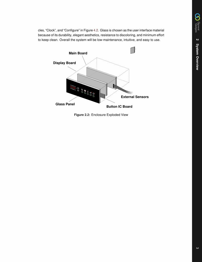
2
System
Overview
3
2
System
Overview
3
2
System
Overview
3
cles ldquoClockrdquo and ldquoConfigurerdquo in Figure 42 Glass is chosen as the user interface materialbecause of its durability elegant aesthetics resistance to discoloring and minimum effortto keep clean Overall the system will be low-maintenance intuitive and easy to use
PM
AM
Clock
Configure
Main Board
Display Board
Button IC BoardGlass Panel
External Sensors
Figure 22 Enclosure Exploded View
3
Sys
tem
s4
3
Sys
tem
s4
3
Sys
tem
s4
3 Systems
31 Motion
System
To prevent the kitchen from being left unattended the Kitchen Alert needs to monitorthe kitchen area Kitchen Alert will accomplish this by the use of a motion detector Bymonitoring the signal from the motion detector the system can determine whether or notthere have been movements in the kitchen in a set time interval which is configurable Ifmotion has not been detected for the set amount of time and the stove is deemed to bein use the user will be alerted to return to the kitchen by an audible warning
Hardware
In deciding the type of motion detector many different types were considered includingultrasonic and infrared The Kitchen Alert system uses an infrared motion detector for thefact that it provides sensitive and high range detection at a low price
Kitchen Alert uses the DC-SS015 Pyroelectric Infrared PIR Motion Detector Module seenin Figures 31 32 This sensor and all its circuitry take up a space of 38mm by 28mmThe motion detector has a range of up to seven meters and 110deg sensing angle [3] Themotion detector will be powered by 5V DC power source The output will be a digitaloutput of 3V high and 0V low The device will send a high signal in 3 second intervalswhile motion is being detected By counting the number of high signals within set intervalsthe Kitchen Alert System is able to determine if a person is present in the kitchen
Figure 31 Motion Sensor Image
PIR
Out
38mm x 28mm
Figure 32 Motion Sensor Schematic
3
System
s
32H
umidity
5
3
System
s
32H
umidity
5
3
System
s
32H
umidity
5
32 Humidity
Hardware
For the purposes of detecting when extra ventilation is required the Honeywell HIH-4031humidity sensor is used The humidity sensor will be placed over the cooking environmentand as such has been chosen to tolerate high temperatures up to 85degC and moderatecondensation [4] The sensor is powered by a 5V source and outputs a linear voltageresponse based on the current humidity The output of the humidity detector is directlyconnected to one of the Analog to Digital (AD) inputs of the microcontroller
Software
The software is responsible for periodically polling the humidity sensor also sharing ADcapture with the temperature and translating the input voltage into the percent humidity
33 Infra-red Temperature
To measure the temperature of the cooking area Kitchen Alert will use an infrared tem-perature sensor Kitchen Alert will use the Rayomatic 4 by Irtec seen in Figure 33 Thissensor has the ability measure temperature from 0degC to 500degC The Sensor is able towithstand up to 90 Relative Humidity and has an Environment Rating of IP65 whichmeans it is completely protected against dust and it is protected against low pressuredjets of water This means that the sensor is able to handle the harsh cooking environmentthe sensor will be placed in
Figure 33 Rayomatic 4 by Irtec [2]
The Rayomatic 4 temperature sensor has an optical resolution of 41 as seen in Fig-ure 34 This means that at the normal counter top height the sensor will cover an areaapproximately equal to the diameter of the cooking pot The sensor will be powered bya 12V DC source and output an analog signal ranging from 0V to 5V The signal fromthe sensor is compensated for the ambient temperature to ensure correct readings Thesignal will be send to an analog to digital converter where the corresponding temperaturereading is determined
3
Sys
tem
s
34
Sm
oke
6
3
Sys
tem
s
34
Sm
oke
6
3
Sys
tem
s
34
Sm
oke
6
Figure 34 Rayomatic 4 Optical Resolution [2]
The Temperature reading will be used in a several ways Firstly the temperature will becompared to a configurable threshold and if the temperature is deemed excessive theuser is alerted of possible dangerous situations The temperature will also be monitoredfor sudden spikes as this could indicate a disaster about to happen The user is alsoable to view the cooking temperature at anytime to assist them in their cooking Thetemperature sensor plays a key role in kitchen safety
34 Smoke
Kitchen Alert will utilize a smoke detector to assist it in determining if there is a danger offire in the kitchen area Kitchen Alert uses a photoelectric smoke detector A photoelectricsmoke detector is sensitive to smoldering fires and visible smoke this allows it to be inclose proximity of the stove without triggering false alarms When smoke is detected thesmoke detector will send out square wave pulses These pulses will be regulated to 5Vdue to the higher voltage output of the smoke detector Kitchen Alert will monitor thenumber of pulses in a set period of time to determine if there is a risk of fire Furthermorein conjunction with the temperature sensor Kitchen Alert will try to distinguish betweentrue and false alarms
4
User
Interface7
4
User
Interface7
4
User
Interface7
4 User Interface
The user interface of Kitchen Alert can be described in two sections input and systemfeedback Input is how users will interact with the system and system feedback is howthe system will show the user the state of the system and the status of their stove area
41 Input Hardware
For user input a set of capacitive touch buttons is provided By using capacitive buttonsthe surface of the device can be smooth providing an easy to clean and sealed envi-ronment for the device For the purposes of the prototype Quantum Research GrouprsquosE1103 kit [5] shown in Figure 41 has been used to supply the button interface Theboard contains a conroller that senses changes in capacitance for 10 buttons The boardoperates off of a 3V power supply while the system operates on 5V For signal recep-tion by the microcontroller 3V is above the logic one cut-off [6] however to protect thebutton IC the logic output of the microcontroller must be down converted from 5V to 3VThis is achieved by a simple diode voltage limiting circuit as shown in Figure A1 As thebuttons supplied with the controller are not of use to us due to being too small and andnot sensitive enough to work through our glass front panel custom buttons (capacitiveplates) have been made to serve this purpose The status of the buttons is transfered tothe microcontroller through a UART interface whenever there is a change in state of thebuttons
Figure 41 E1103 Button Board
4
Use
rIn
terf
ace
4
2In
put
Beh
avio
ur8
4
Use
rIn
terf
ace
4
2In
put
Beh
avio
ur8
4
Use
rIn
terf
ace
4
2In
put
Beh
avio
ur8
42 Input Behaviour
The users of Kitchen Alert will provide input into the system via a series of buttons de-scribed above There are nine buttons and the breakdown of them is six for subsystemselect and onoff where applicable two arrow buttons for configuration adjustments andone button to enter configuration mode Whenever a button is pressed an interrupt isgenerated and the system will determine which button is pressed To make it intuitivefor users Kitchen Alert will have a mix of symbols and text labels by each of the inputbuttons as shown in Figure 42
PMAM
Clock
Configure
Status Alerts
Buttons
Figure 42 User Interface
For the six subsystem select buttons a press of the button will switch the system into thatcorresponding subsystem mode Holding a subsystem button for three seconds can turnoff that mode with the exception of the clock Once a subsystem is turned off the systemwill default back to the clock Holding a subsystem button for three seconds will also turnon a subsystem that is off After turning a subsystem on the system will also enter thatsubsystem mode For the case when the system generates an alert the user can turn offthe alert for 30 seconds to correct the situation by pressing the corresponding subsystemthat the alert is for
When the configure button is pressed the system will enter the configuration mode forthe subsystem mode that it was just in While in configuration mode adjustments toparameter pertaining to the current subsystem can be made via the up and down arrowsWhen the system recognizes that the user has stopped changing the parameter for 3seconds configuration mode will timeout and return to the previous subsystem modeThe following Figure 43 and Table 41 further explain the procedure
4
User
Interface
42Input
Behaviour
9
4
User
Interface
42Input
Behaviour
9
4
User
Interface
42Input
Behaviour
9
SystemConfigurable
Y
N
A System Button Pressed
ConfigurationButton Pressed
End
System StatusLight ON
LED DisplayBlink OFF
Arrow Button Activity In Last 3s
LED DisplayBlink ON
End
System StatusLight OFF
N
Y
Play ButtonError Sound
Play ConfigComplete Sound
Figure 43 Configuration Flow
Table 41 Configuration Behaviour
Subsystem Parameter Up Arrow Down Arrow
Clock Clock Increases Time Decreases Time
Humidity Humidity Threshold Increases up to 100 Decreases down to 40
Temperature Temperature Threshold Increases up to 450degC Decreases down to 50degC
Timer Time to Countdown Increases up to 12 hours Decreases down to 1 min
Motion Allowable Time for No Motion Increases up to 12 hours Decreases down to 1 min
4
Use
rIn
terf
ace
4
3Fe
edba
ckH
ardw
are
10
4
Use
rIn
terf
ace
4
3Fe
edba
ckH
ardw
are
10
4
Use
rIn
terf
ace
4
3Fe
edba
ckH
ardw
are
10
43 Feedback Hardware
LED Display
To supply user information such as time temperature and humidity a numeric LED dis-play is used as shown in Figure 44 The LED display was chosen as its high brightnessallows it to be used behind the glass This particular display is a common cathode displayThere is only one set of inputs for the 7 segments and 5 lines for the each of the digitsThis means the display must be multiplexed in order to turn on more than one digit atonce In addition a BCD decoder is used both to reduce pin outs from the microcontrollerand to decrease the current the microcontroller must supply The cathode connection foreach digit is passed into a pnp-transistor which is operated as a switch by varying thevoltage on the base by the microcontroller This serves two purposes first it means themicrocontoller does not need to sink the current flowing through the LEDs and it preventsthe reverse voltage on the LEDs from exceeding their maximum spec of 5V [7]
PMAM
Figure 44 LED Display Unit
LEDs IOExpander
A 16-bit IO Expander with SPI interface is used to drive the green and red LEDs foronoff status and alert status indication The IO expander is connected to the microcon-troller via four pins chip select serial clock serial in and serial out With just those fourconnections the IO expander provides a total of 16 available IO pins making it greatpin saving piece of hardware to complement the microcontroller To write to the IO ex-pander the microcontroller first enables the chip select Then the address of the registerthat controls the output pin is sent followed by the data of which pin and correspondingLED is high or lit
Buzzer
The purpose of the buzzer is to play back warning sounds to inform the user when a criticalrisk level is detected around the stovetop As a secondary function it will accompany thebutton controller by generating short beeps when a button is pressed This is designed toenhance feedback when working with the touch-sensitive buttons on the user interfaceThe sounds played through the alarm system will be generated using the microcontrollerrsquosonboard Pulse Width Modulation (PWM) and an additional timer (Timer3)
For button beeps the PWM will use Timer2 on the MCU to generate a square wave at16 kHz and Timer3 will modulate the waversquos duty cycle to vary the average voltage atthe output at 12 data points per desired output period The output will be filtered usinga passive RC circuit to resemble a sine wave To generate warning sounds only the
4
User
Interface
43Feedback
Hardw
are11
4
User
Interface
43Feedback
Hardw
are11
4
User
Interface
43Feedback
Hardw
are11
square wave from the PWM will be used as the output Due to the nature of the squarewave output it is more effective in alarming situations compared to sine waves Detailsfor buzzer sounds which will be used are listed in Table 42
Table 42 Buzzer Modes and Attributes
Buzzer Mode Waveform PWMFrequency
Timer 3Frequency
OutputFrequency
OutputCharacteristic
Critical Alert Square 2 kHz - 2 kHz Intermittent period of500ms 50 onoffduty cycle
Warning Square 2 kHz - 2 kHz Intermittent period of1s 50 onoff dutycycle
Timer Expiry Sine 16 kHz 12 kHz 1 kHz Continuous
Button Press Sine 16 kHz 6 kHz 500 Hz 200ms beep
SuccessfulConfiguration
Sine 16 kHz 72 kHz 600 Hz Two 100ms beepswith a 50ms pause inbetween
Invalid ButtonInput
Square 100 Hz - 100 Hz 200ms beep
The alarm hardware we have chosen is the Murata PIEZORINGERreg specificall thePKM44EWH1001C model PIEZORINGERreg is an EU Restriction of Hazardous Sub-stances Directive (RoHS) compliant lightweight piezoelectric speaker which can be di-rectly driven from ICs with negligible power consumption [8] The piezoelectric speakerwill be connected to the MCUrsquos PWM output pin as shown in Figure 45 The simple RClow-pass filter is designed to filter out the 16kHz PWM base frequency for generating sinewaves The cutoff frequency for the low- pass filter is given by
fc =1
2πRC=
1
2π x 22kΩ x 5nF= 145kHz (41)
5nF
2k2 VoutVin
To Piezo
Figure 45 Low-pass Filter for Piezoelectric Speaker
4
Use
rIn
terf
ace
4
4Fe
edba
ckB
ehav
iour
12
4
Use
rIn
terf
ace
4
4Fe
edba
ckB
ehav
iour
12
4
Use
rIn
terf
ace
4
4Fe
edba
ckB
ehav
iour
12
44 Feedback Behaviour
The Kitchen Alert system has the need to communicate s significant amount of informationto the user The onoff status the warning or alert status and the different parameters ofthe different subsystems all must be indicated in a clear and precise manner
To indicate the onoff status of each subsystem green LEDs will be placed behind thebuttons of the corresponding subsystem They will be lit whenever the subsystem is onand unlit when it is off To indicate an alert for a subsystem red LEDs will be placed abovethe subsystemrsquos button by the corresponding symbol The red LEDs will light wheneverthere is an alert from that subsystem
A numeric LED display will be used to display the parameters of the different subsystemsBecause there are both normal and configuration modes for all the subsystems blinkingof the LED display will be used to differentiate the too modes The table below showswhat will be displayed from the subsystems in the different modes
Table 43 Config Display
Subsystem Display Parameter Configuration Display Parameter (blinking)
Clock Time Time
Humidity Current Humidity Humidity Threshold
Temperature Current Temperature Temperature Threshold
Timer Countdown Timer Time to Countdown From
Motion Time Since Last Motion Allowable Time for No Motion
5
TestP
lan13
5
TestP
lan13
5
TestP
lan13
5 Test Plan
To ensure that the system works to specification a test plan along with test cases havebeen created Whenever the system is changed it must be tested against these testcases Each sub-system will have its own separate test case
Test Case 1System ClockTimeDescription Testing the functionality of setting the clock
Step Action Expected Results Pass Fail Comments
1 Turn System On LED Display will blink to setTime
2 Use Arrow Buttons to set cur-rent time When finished re-main inactive for 3 seconds
The Clock will be set and dis-plays current time
3 While in Clock mode pressconfigure button
The Clock will enter Configu-ration mode
4 Set the clock to a new timeusing arrow buttons Whenfinished remain inactive for3 seconds
The Clock will display newtime
Test Case 2System Humidity SensorDescription Testing of turning the humidity sensor on or off and setting the humiditythreshold
Step Action Expected Results Pass Fail Comments
1 When system is on pressthe humidity button Com-pare results with external hu-midity sensor
LED Display will Display cur-rent humidity
2 Press configure button The Status LED for the Hu-midity system will blink
3 Use the arrow buttons andset the humidity threshold to50 When finished remaininactive for 3 seconds
The new threshold will be50 and Status LED willbecome steady
4 Expose the system to smallamount of steam from boilingwater
The FanIndicator will turn ononce the 50 threshold isreached
5
Test
Pla
n14
5
Test
Pla
n14
5
Test
Pla
n14
Step Action Expected Results Pass Fail Comments
5 Press and hold the humiditybutton for 3 seconds
The Humidity system will turnoff and the Status LED willturn off
6 Press and hold the humiditybutton for 3 seconds
The Humidity system will turnon and the Status LED willturn on
Test Case 3System Temperature SensorDescription Testing of turning the Temperature sensor on or off and setting the Tem-perature sensorrsquos threshold
Step Action Expected Results Pass Fail Comments
1 When system is on pressthe Temperature Compareresults with external an ex-ternal thermometer
LED Display will Display cur-rent temperature
2 Press configure button The Status LED for the Tem-perature system will blink
3 Use the arrow buttons andset the Temperature thresh-old to 90degC When finishedremain inactive for 3 sec-onds
The new threshold will be90degC Status LED will be-come steady
4 Boil a pot of water on thestove
The system will set off thealarm and alert the user tocome back to the kitchen
5 Press the Temperature but-ton
The Alarm will turn off for 30seconds
6 Press and hold the Temper-ature button for 3 seconds
The Temperature system willturn off and the Status LEDwill turn off
7 Press and hold the Temper-ature button for 3 seconds
The Temperature system willturn on and the Status LEDwill turn on
5
TestP
lan15
5
TestP
lan15
5
TestP
lan15
Test Case 4System TimerDescription This test case will test the functionality of the timer system
Step Action Expected Results Pass Fail Comments
1 When system is on Pressthe Timer button followed bythe Configure button
The system will enter timerconfiguration setting TheStatus LED for the Timersystem will blink
2 Use the arrow buttons andset the Timer to 30 secondsWhen finished remain inac-tive for 3 seconds
The timer will start countingdown from 30 seconds Sta-tus LED will become steady
3 Press and hold the timer but-ton
The status LED for the Timerwill turn off The counter willstop its count down
4 Press and hold the timer but-ton
The status LED for the Timerwill turn On The counter willcontinue its count down
5 Wait until timer expires The timerrsquos alarm will turn on
Test Case 5System Motion DetectorDescription This test case will test the functionality of the Motion Detector system
Step Action Expected Results Pass Fail Comments
1 When system is on Pressthe Motion detection buttonfollowed by the Configurebutton
The system will enter motionconfiguration setting TheStatus LED for the motionsystem will blink
2 Use the arrow buttons andset the threshold to 10 sec-onds When finished remaininactive for 3 seconds
The motion detectorrsquos timerwill be set to 10 secondsStatus LED will becomesteady
3 Leave the vicinity of the sys-tem for 10 seconds
The system will alert the userto return to the kitchen
4 Return to the system The alert will stop
6
Con
clus
ion
16
6
Con
clus
ion
16
6
Con
clus
ion
16
6 Conclusion
General Gadgets Canada approves the design specifications contained in this report Byoutlining the specific behaviors in the various modes the Kitchen Alert prototype will bebuilt to operate in the desired manner for the different conditions that it will encounter Toverify the behaviors the Kitchen Alert system will be put through the comprehensive andsystematic test plan described in this report Members of the General Gadgets Canadawill frequently reference these specifications during the development schedule The pro-totype for Kitchen Alert is projected for completion in April 2009
R
eferences17
R
eferences17
R
eferences17
References
[1] General Gadgets Canada ldquoFunctional Specs Kitchen Alertrdquo February 2009 Version10
[2] Temperature amp Process Instruments Inc ldquoIRtec Rayomatic 4 Infrared Fixed MountThermometerrdquo [Online] Available httpwwwtnp-instrumentscomrayomatic4_infrared_thermometerhtml
[3] Sure Electronics ldquoPyroelectric Infrared PIR Motion Sensor Detector Module UserGuide DC-SS105_Ver10rdquo
[4] Honeywell ldquoHIH-403031 Series Humidity Sensorsrdquo [Online] Available httpsensinghoneywellcomindexcfmci_id142958la_id1document1re_id0
[5] Quantum Research Group ldquoE1103 Evaluation Assembly User Guiderdquo [Online]Available wwwatmelcomdynresourcesprod_documentsE1103_100pdf
[6] Microchip Technology ldquoPIC18F2525262045254620 Data Sheetrdquo [Online] Avail-able httpww1microchipcomdownloadsenDeviceDoc39626epdf
[7] Lite-on Electronics Inc ldquoLTC-4727JR Data Sheetrdquo [Online] Available httpmediadigikeycompdfData20SheetsLite-On20PDFsLTC-4727JRpdf
[8] Murata Manufacturing Co Ltd ldquoPiezoelectric Sound Componentsrdquo [Online]Available httpwwwmuratacomcatalogp37epdf
A
Sch
emat
ics
18
A
Sch
emat
ics
18
A
Sch
emat
ics
18
A Schematics
LD
DC
DB
DD
DA
PH
BI
VSS
VDD
Of
Og
Oe
Od
Oc
Ob
Oa
HEF4
543B
2k2
2k2
2k2
2k2
2k2
2k2
2k2
Display Board
Main Board
Buttons10
1nF
MCLRRE3
RA0AN0
RA1AN1
RA2AN2
RA3AN3
RA4
RA5
RE0
RE1
RE2
VDD
VSS
OSC1
OSC2
RC0
RC1CCP2
RC2CPP1
RC3SCK
RD0
RD1
RB7PGD
RB6PGC
RB5PGM
RB4
RB3
RB2INT2
RB1INT1
RB0INT0
VDD
VSS
RD7
RD6
RD5
RD4
RC7RX
RC6TX
RC5SDO
RC4SDI
RD3
RD2
PIC
18F4
620
1nF
1nF
ICSP
1nF5V
5V
5V
5V 5V
SPI
HumidityTemperature
piezo2k2
5nF
B0
B1
B2
B3
B4
B5
B6
B7
VDD
VSS
CS
SCK
SI
SO
A7
A6
A5
A4
A3
A2
A1
A0
INTA
INTB
RESET
A2
A1
A0
MCP23
S17
Low-pass
Button Board
1nF
100k
Indi
cato
rs
Indicators
SmokeDetector
MotionDetector
3V
1k8
3V
1k8
CHANGE TX RX
AMPM
RST
Figure A1 System Schematic
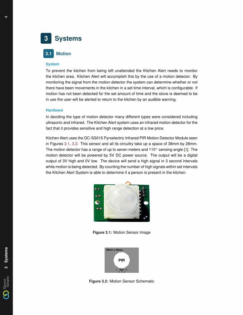
3
Sys
tem
s4
3
Sys
tem
s4
3
Sys
tem
s4
3 Systems
31 Motion
System
To prevent the kitchen from being left unattended the Kitchen Alert needs to monitorthe kitchen area Kitchen Alert will accomplish this by the use of a motion detector Bymonitoring the signal from the motion detector the system can determine whether or notthere have been movements in the kitchen in a set time interval which is configurable Ifmotion has not been detected for the set amount of time and the stove is deemed to bein use the user will be alerted to return to the kitchen by an audible warning
Hardware
In deciding the type of motion detector many different types were considered includingultrasonic and infrared The Kitchen Alert system uses an infrared motion detector for thefact that it provides sensitive and high range detection at a low price
Kitchen Alert uses the DC-SS015 Pyroelectric Infrared PIR Motion Detector Module seenin Figures 31 32 This sensor and all its circuitry take up a space of 38mm by 28mmThe motion detector has a range of up to seven meters and 110deg sensing angle [3] Themotion detector will be powered by 5V DC power source The output will be a digitaloutput of 3V high and 0V low The device will send a high signal in 3 second intervalswhile motion is being detected By counting the number of high signals within set intervalsthe Kitchen Alert System is able to determine if a person is present in the kitchen
Figure 31 Motion Sensor Image
PIR
Out
38mm x 28mm
Figure 32 Motion Sensor Schematic
3
System
s
32H
umidity
5
3
System
s
32H
umidity
5
3
System
s
32H
umidity
5
32 Humidity
Hardware
For the purposes of detecting when extra ventilation is required the Honeywell HIH-4031humidity sensor is used The humidity sensor will be placed over the cooking environmentand as such has been chosen to tolerate high temperatures up to 85degC and moderatecondensation [4] The sensor is powered by a 5V source and outputs a linear voltageresponse based on the current humidity The output of the humidity detector is directlyconnected to one of the Analog to Digital (AD) inputs of the microcontroller
Software
The software is responsible for periodically polling the humidity sensor also sharing ADcapture with the temperature and translating the input voltage into the percent humidity
33 Infra-red Temperature
To measure the temperature of the cooking area Kitchen Alert will use an infrared tem-perature sensor Kitchen Alert will use the Rayomatic 4 by Irtec seen in Figure 33 Thissensor has the ability measure temperature from 0degC to 500degC The Sensor is able towithstand up to 90 Relative Humidity and has an Environment Rating of IP65 whichmeans it is completely protected against dust and it is protected against low pressuredjets of water This means that the sensor is able to handle the harsh cooking environmentthe sensor will be placed in
Figure 33 Rayomatic 4 by Irtec [2]
The Rayomatic 4 temperature sensor has an optical resolution of 41 as seen in Fig-ure 34 This means that at the normal counter top height the sensor will cover an areaapproximately equal to the diameter of the cooking pot The sensor will be powered bya 12V DC source and output an analog signal ranging from 0V to 5V The signal fromthe sensor is compensated for the ambient temperature to ensure correct readings Thesignal will be send to an analog to digital converter where the corresponding temperaturereading is determined
3
Sys
tem
s
34
Sm
oke
6
3
Sys
tem
s
34
Sm
oke
6
3
Sys
tem
s
34
Sm
oke
6
Figure 34 Rayomatic 4 Optical Resolution [2]
The Temperature reading will be used in a several ways Firstly the temperature will becompared to a configurable threshold and if the temperature is deemed excessive theuser is alerted of possible dangerous situations The temperature will also be monitoredfor sudden spikes as this could indicate a disaster about to happen The user is alsoable to view the cooking temperature at anytime to assist them in their cooking Thetemperature sensor plays a key role in kitchen safety
34 Smoke
Kitchen Alert will utilize a smoke detector to assist it in determining if there is a danger offire in the kitchen area Kitchen Alert uses a photoelectric smoke detector A photoelectricsmoke detector is sensitive to smoldering fires and visible smoke this allows it to be inclose proximity of the stove without triggering false alarms When smoke is detected thesmoke detector will send out square wave pulses These pulses will be regulated to 5Vdue to the higher voltage output of the smoke detector Kitchen Alert will monitor thenumber of pulses in a set period of time to determine if there is a risk of fire Furthermorein conjunction with the temperature sensor Kitchen Alert will try to distinguish betweentrue and false alarms
4
User
Interface7
4
User
Interface7
4
User
Interface7
4 User Interface
The user interface of Kitchen Alert can be described in two sections input and systemfeedback Input is how users will interact with the system and system feedback is howthe system will show the user the state of the system and the status of their stove area
41 Input Hardware
For user input a set of capacitive touch buttons is provided By using capacitive buttonsthe surface of the device can be smooth providing an easy to clean and sealed envi-ronment for the device For the purposes of the prototype Quantum Research GrouprsquosE1103 kit [5] shown in Figure 41 has been used to supply the button interface Theboard contains a conroller that senses changes in capacitance for 10 buttons The boardoperates off of a 3V power supply while the system operates on 5V For signal recep-tion by the microcontroller 3V is above the logic one cut-off [6] however to protect thebutton IC the logic output of the microcontroller must be down converted from 5V to 3VThis is achieved by a simple diode voltage limiting circuit as shown in Figure A1 As thebuttons supplied with the controller are not of use to us due to being too small and andnot sensitive enough to work through our glass front panel custom buttons (capacitiveplates) have been made to serve this purpose The status of the buttons is transfered tothe microcontroller through a UART interface whenever there is a change in state of thebuttons
Figure 41 E1103 Button Board
4
Use
rIn
terf
ace
4
2In
put
Beh
avio
ur8
4
Use
rIn
terf
ace
4
2In
put
Beh
avio
ur8
4
Use
rIn
terf
ace
4
2In
put
Beh
avio
ur8
42 Input Behaviour
The users of Kitchen Alert will provide input into the system via a series of buttons de-scribed above There are nine buttons and the breakdown of them is six for subsystemselect and onoff where applicable two arrow buttons for configuration adjustments andone button to enter configuration mode Whenever a button is pressed an interrupt isgenerated and the system will determine which button is pressed To make it intuitivefor users Kitchen Alert will have a mix of symbols and text labels by each of the inputbuttons as shown in Figure 42
PMAM
Clock
Configure
Status Alerts
Buttons
Figure 42 User Interface
For the six subsystem select buttons a press of the button will switch the system into thatcorresponding subsystem mode Holding a subsystem button for three seconds can turnoff that mode with the exception of the clock Once a subsystem is turned off the systemwill default back to the clock Holding a subsystem button for three seconds will also turnon a subsystem that is off After turning a subsystem on the system will also enter thatsubsystem mode For the case when the system generates an alert the user can turn offthe alert for 30 seconds to correct the situation by pressing the corresponding subsystemthat the alert is for
When the configure button is pressed the system will enter the configuration mode forthe subsystem mode that it was just in While in configuration mode adjustments toparameter pertaining to the current subsystem can be made via the up and down arrowsWhen the system recognizes that the user has stopped changing the parameter for 3seconds configuration mode will timeout and return to the previous subsystem modeThe following Figure 43 and Table 41 further explain the procedure
4
User
Interface
42Input
Behaviour
9
4
User
Interface
42Input
Behaviour
9
4
User
Interface
42Input
Behaviour
9
SystemConfigurable
Y
N
A System Button Pressed
ConfigurationButton Pressed
End
System StatusLight ON
LED DisplayBlink OFF
Arrow Button Activity In Last 3s
LED DisplayBlink ON
End
System StatusLight OFF
N
Y
Play ButtonError Sound
Play ConfigComplete Sound
Figure 43 Configuration Flow
Table 41 Configuration Behaviour
Subsystem Parameter Up Arrow Down Arrow
Clock Clock Increases Time Decreases Time
Humidity Humidity Threshold Increases up to 100 Decreases down to 40
Temperature Temperature Threshold Increases up to 450degC Decreases down to 50degC
Timer Time to Countdown Increases up to 12 hours Decreases down to 1 min
Motion Allowable Time for No Motion Increases up to 12 hours Decreases down to 1 min
4
Use
rIn
terf
ace
4
3Fe
edba
ckH
ardw
are
10
4
Use
rIn
terf
ace
4
3Fe
edba
ckH
ardw
are
10
4
Use
rIn
terf
ace
4
3Fe
edba
ckH
ardw
are
10
43 Feedback Hardware
LED Display
To supply user information such as time temperature and humidity a numeric LED dis-play is used as shown in Figure 44 The LED display was chosen as its high brightnessallows it to be used behind the glass This particular display is a common cathode displayThere is only one set of inputs for the 7 segments and 5 lines for the each of the digitsThis means the display must be multiplexed in order to turn on more than one digit atonce In addition a BCD decoder is used both to reduce pin outs from the microcontrollerand to decrease the current the microcontroller must supply The cathode connection foreach digit is passed into a pnp-transistor which is operated as a switch by varying thevoltage on the base by the microcontroller This serves two purposes first it means themicrocontoller does not need to sink the current flowing through the LEDs and it preventsthe reverse voltage on the LEDs from exceeding their maximum spec of 5V [7]
PMAM
Figure 44 LED Display Unit
LEDs IOExpander
A 16-bit IO Expander with SPI interface is used to drive the green and red LEDs foronoff status and alert status indication The IO expander is connected to the microcon-troller via four pins chip select serial clock serial in and serial out With just those fourconnections the IO expander provides a total of 16 available IO pins making it greatpin saving piece of hardware to complement the microcontroller To write to the IO ex-pander the microcontroller first enables the chip select Then the address of the registerthat controls the output pin is sent followed by the data of which pin and correspondingLED is high or lit
Buzzer
The purpose of the buzzer is to play back warning sounds to inform the user when a criticalrisk level is detected around the stovetop As a secondary function it will accompany thebutton controller by generating short beeps when a button is pressed This is designed toenhance feedback when working with the touch-sensitive buttons on the user interfaceThe sounds played through the alarm system will be generated using the microcontrollerrsquosonboard Pulse Width Modulation (PWM) and an additional timer (Timer3)
For button beeps the PWM will use Timer2 on the MCU to generate a square wave at16 kHz and Timer3 will modulate the waversquos duty cycle to vary the average voltage atthe output at 12 data points per desired output period The output will be filtered usinga passive RC circuit to resemble a sine wave To generate warning sounds only the
4
User
Interface
43Feedback
Hardw
are11
4
User
Interface
43Feedback
Hardw
are11
4
User
Interface
43Feedback
Hardw
are11
square wave from the PWM will be used as the output Due to the nature of the squarewave output it is more effective in alarming situations compared to sine waves Detailsfor buzzer sounds which will be used are listed in Table 42
Table 42 Buzzer Modes and Attributes
Buzzer Mode Waveform PWMFrequency
Timer 3Frequency
OutputFrequency
OutputCharacteristic
Critical Alert Square 2 kHz - 2 kHz Intermittent period of500ms 50 onoffduty cycle
Warning Square 2 kHz - 2 kHz Intermittent period of1s 50 onoff dutycycle
Timer Expiry Sine 16 kHz 12 kHz 1 kHz Continuous
Button Press Sine 16 kHz 6 kHz 500 Hz 200ms beep
SuccessfulConfiguration
Sine 16 kHz 72 kHz 600 Hz Two 100ms beepswith a 50ms pause inbetween
Invalid ButtonInput
Square 100 Hz - 100 Hz 200ms beep
The alarm hardware we have chosen is the Murata PIEZORINGERreg specificall thePKM44EWH1001C model PIEZORINGERreg is an EU Restriction of Hazardous Sub-stances Directive (RoHS) compliant lightweight piezoelectric speaker which can be di-rectly driven from ICs with negligible power consumption [8] The piezoelectric speakerwill be connected to the MCUrsquos PWM output pin as shown in Figure 45 The simple RClow-pass filter is designed to filter out the 16kHz PWM base frequency for generating sinewaves The cutoff frequency for the low- pass filter is given by
fc =1
2πRC=
1
2π x 22kΩ x 5nF= 145kHz (41)
5nF
2k2 VoutVin
To Piezo
Figure 45 Low-pass Filter for Piezoelectric Speaker
4
Use
rIn
terf
ace
4
4Fe
edba
ckB
ehav
iour
12
4
Use
rIn
terf
ace
4
4Fe
edba
ckB
ehav
iour
12
4
Use
rIn
terf
ace
4
4Fe
edba
ckB
ehav
iour
12
44 Feedback Behaviour
The Kitchen Alert system has the need to communicate s significant amount of informationto the user The onoff status the warning or alert status and the different parameters ofthe different subsystems all must be indicated in a clear and precise manner
To indicate the onoff status of each subsystem green LEDs will be placed behind thebuttons of the corresponding subsystem They will be lit whenever the subsystem is onand unlit when it is off To indicate an alert for a subsystem red LEDs will be placed abovethe subsystemrsquos button by the corresponding symbol The red LEDs will light wheneverthere is an alert from that subsystem
A numeric LED display will be used to display the parameters of the different subsystemsBecause there are both normal and configuration modes for all the subsystems blinkingof the LED display will be used to differentiate the too modes The table below showswhat will be displayed from the subsystems in the different modes
Table 43 Config Display
Subsystem Display Parameter Configuration Display Parameter (blinking)
Clock Time Time
Humidity Current Humidity Humidity Threshold
Temperature Current Temperature Temperature Threshold
Timer Countdown Timer Time to Countdown From
Motion Time Since Last Motion Allowable Time for No Motion
5
TestP
lan13
5
TestP
lan13
5
TestP
lan13
5 Test Plan
To ensure that the system works to specification a test plan along with test cases havebeen created Whenever the system is changed it must be tested against these testcases Each sub-system will have its own separate test case
Test Case 1System ClockTimeDescription Testing the functionality of setting the clock
Step Action Expected Results Pass Fail Comments
1 Turn System On LED Display will blink to setTime
2 Use Arrow Buttons to set cur-rent time When finished re-main inactive for 3 seconds
The Clock will be set and dis-plays current time
3 While in Clock mode pressconfigure button
The Clock will enter Configu-ration mode
4 Set the clock to a new timeusing arrow buttons Whenfinished remain inactive for3 seconds
The Clock will display newtime
Test Case 2System Humidity SensorDescription Testing of turning the humidity sensor on or off and setting the humiditythreshold
Step Action Expected Results Pass Fail Comments
1 When system is on pressthe humidity button Com-pare results with external hu-midity sensor
LED Display will Display cur-rent humidity
2 Press configure button The Status LED for the Hu-midity system will blink
3 Use the arrow buttons andset the humidity threshold to50 When finished remaininactive for 3 seconds
The new threshold will be50 and Status LED willbecome steady
4 Expose the system to smallamount of steam from boilingwater
The FanIndicator will turn ononce the 50 threshold isreached
5
Test
Pla
n14
5
Test
Pla
n14
5
Test
Pla
n14
Step Action Expected Results Pass Fail Comments
5 Press and hold the humiditybutton for 3 seconds
The Humidity system will turnoff and the Status LED willturn off
6 Press and hold the humiditybutton for 3 seconds
The Humidity system will turnon and the Status LED willturn on
Test Case 3System Temperature SensorDescription Testing of turning the Temperature sensor on or off and setting the Tem-perature sensorrsquos threshold
Step Action Expected Results Pass Fail Comments
1 When system is on pressthe Temperature Compareresults with external an ex-ternal thermometer
LED Display will Display cur-rent temperature
2 Press configure button The Status LED for the Tem-perature system will blink
3 Use the arrow buttons andset the Temperature thresh-old to 90degC When finishedremain inactive for 3 sec-onds
The new threshold will be90degC Status LED will be-come steady
4 Boil a pot of water on thestove
The system will set off thealarm and alert the user tocome back to the kitchen
5 Press the Temperature but-ton
The Alarm will turn off for 30seconds
6 Press and hold the Temper-ature button for 3 seconds
The Temperature system willturn off and the Status LEDwill turn off
7 Press and hold the Temper-ature button for 3 seconds
The Temperature system willturn on and the Status LEDwill turn on
5
TestP
lan15
5
TestP
lan15
5
TestP
lan15
Test Case 4System TimerDescription This test case will test the functionality of the timer system
Step Action Expected Results Pass Fail Comments
1 When system is on Pressthe Timer button followed bythe Configure button
The system will enter timerconfiguration setting TheStatus LED for the Timersystem will blink
2 Use the arrow buttons andset the Timer to 30 secondsWhen finished remain inac-tive for 3 seconds
The timer will start countingdown from 30 seconds Sta-tus LED will become steady
3 Press and hold the timer but-ton
The status LED for the Timerwill turn off The counter willstop its count down
4 Press and hold the timer but-ton
The status LED for the Timerwill turn On The counter willcontinue its count down
5 Wait until timer expires The timerrsquos alarm will turn on
Test Case 5System Motion DetectorDescription This test case will test the functionality of the Motion Detector system
Step Action Expected Results Pass Fail Comments
1 When system is on Pressthe Motion detection buttonfollowed by the Configurebutton
The system will enter motionconfiguration setting TheStatus LED for the motionsystem will blink
2 Use the arrow buttons andset the threshold to 10 sec-onds When finished remaininactive for 3 seconds
The motion detectorrsquos timerwill be set to 10 secondsStatus LED will becomesteady
3 Leave the vicinity of the sys-tem for 10 seconds
The system will alert the userto return to the kitchen
4 Return to the system The alert will stop
6
Con
clus
ion
16
6
Con
clus
ion
16
6
Con
clus
ion
16
6 Conclusion
General Gadgets Canada approves the design specifications contained in this report Byoutlining the specific behaviors in the various modes the Kitchen Alert prototype will bebuilt to operate in the desired manner for the different conditions that it will encounter Toverify the behaviors the Kitchen Alert system will be put through the comprehensive andsystematic test plan described in this report Members of the General Gadgets Canadawill frequently reference these specifications during the development schedule The pro-totype for Kitchen Alert is projected for completion in April 2009
R
eferences17
R
eferences17
R
eferences17
References
[1] General Gadgets Canada ldquoFunctional Specs Kitchen Alertrdquo February 2009 Version10
[2] Temperature amp Process Instruments Inc ldquoIRtec Rayomatic 4 Infrared Fixed MountThermometerrdquo [Online] Available httpwwwtnp-instrumentscomrayomatic4_infrared_thermometerhtml
[3] Sure Electronics ldquoPyroelectric Infrared PIR Motion Sensor Detector Module UserGuide DC-SS105_Ver10rdquo
[4] Honeywell ldquoHIH-403031 Series Humidity Sensorsrdquo [Online] Available httpsensinghoneywellcomindexcfmci_id142958la_id1document1re_id0
[5] Quantum Research Group ldquoE1103 Evaluation Assembly User Guiderdquo [Online]Available wwwatmelcomdynresourcesprod_documentsE1103_100pdf
[6] Microchip Technology ldquoPIC18F2525262045254620 Data Sheetrdquo [Online] Avail-able httpww1microchipcomdownloadsenDeviceDoc39626epdf
[7] Lite-on Electronics Inc ldquoLTC-4727JR Data Sheetrdquo [Online] Available httpmediadigikeycompdfData20SheetsLite-On20PDFsLTC-4727JRpdf
[8] Murata Manufacturing Co Ltd ldquoPiezoelectric Sound Componentsrdquo [Online]Available httpwwwmuratacomcatalogp37epdf
A
Sch
emat
ics
18
A
Sch
emat
ics
18
A
Sch
emat
ics
18
A Schematics
LD
DC
DB
DD
DA
PH
BI
VSS
VDD
Of
Og
Oe
Od
Oc
Ob
Oa
HEF4
543B
2k2
2k2
2k2
2k2
2k2
2k2
2k2
Display Board
Main Board
Buttons10
1nF
MCLRRE3
RA0AN0
RA1AN1
RA2AN2
RA3AN3
RA4
RA5
RE0
RE1
RE2
VDD
VSS
OSC1
OSC2
RC0
RC1CCP2
RC2CPP1
RC3SCK
RD0
RD1
RB7PGD
RB6PGC
RB5PGM
RB4
RB3
RB2INT2
RB1INT1
RB0INT0
VDD
VSS
RD7
RD6
RD5
RD4
RC7RX
RC6TX
RC5SDO
RC4SDI
RD3
RD2
PIC
18F4
620
1nF
1nF
ICSP
1nF5V
5V
5V
5V 5V
SPI
HumidityTemperature
piezo2k2
5nF
B0
B1
B2
B3
B4
B5
B6
B7
VDD
VSS
CS
SCK
SI
SO
A7
A6
A5
A4
A3
A2
A1
A0
INTA
INTB
RESET
A2
A1
A0
MCP23
S17
Low-pass
Button Board
1nF
100k
Indi
cato
rs
Indicators
SmokeDetector
MotionDetector
3V
1k8
3V
1k8
CHANGE TX RX
AMPM
RST
Figure A1 System Schematic

3
System
s
32H
umidity
5
3
System
s
32H
umidity
5
3
System
s
32H
umidity
5
32 Humidity
Hardware
For the purposes of detecting when extra ventilation is required the Honeywell HIH-4031humidity sensor is used The humidity sensor will be placed over the cooking environmentand as such has been chosen to tolerate high temperatures up to 85degC and moderatecondensation [4] The sensor is powered by a 5V source and outputs a linear voltageresponse based on the current humidity The output of the humidity detector is directlyconnected to one of the Analog to Digital (AD) inputs of the microcontroller
Software
The software is responsible for periodically polling the humidity sensor also sharing ADcapture with the temperature and translating the input voltage into the percent humidity
33 Infra-red Temperature
To measure the temperature of the cooking area Kitchen Alert will use an infrared tem-perature sensor Kitchen Alert will use the Rayomatic 4 by Irtec seen in Figure 33 Thissensor has the ability measure temperature from 0degC to 500degC The Sensor is able towithstand up to 90 Relative Humidity and has an Environment Rating of IP65 whichmeans it is completely protected against dust and it is protected against low pressuredjets of water This means that the sensor is able to handle the harsh cooking environmentthe sensor will be placed in
Figure 33 Rayomatic 4 by Irtec [2]
The Rayomatic 4 temperature sensor has an optical resolution of 41 as seen in Fig-ure 34 This means that at the normal counter top height the sensor will cover an areaapproximately equal to the diameter of the cooking pot The sensor will be powered bya 12V DC source and output an analog signal ranging from 0V to 5V The signal fromthe sensor is compensated for the ambient temperature to ensure correct readings Thesignal will be send to an analog to digital converter where the corresponding temperaturereading is determined
3
Sys
tem
s
34
Sm
oke
6
3
Sys
tem
s
34
Sm
oke
6
3
Sys
tem
s
34
Sm
oke
6
Figure 34 Rayomatic 4 Optical Resolution [2]
The Temperature reading will be used in a several ways Firstly the temperature will becompared to a configurable threshold and if the temperature is deemed excessive theuser is alerted of possible dangerous situations The temperature will also be monitoredfor sudden spikes as this could indicate a disaster about to happen The user is alsoable to view the cooking temperature at anytime to assist them in their cooking Thetemperature sensor plays a key role in kitchen safety
34 Smoke
Kitchen Alert will utilize a smoke detector to assist it in determining if there is a danger offire in the kitchen area Kitchen Alert uses a photoelectric smoke detector A photoelectricsmoke detector is sensitive to smoldering fires and visible smoke this allows it to be inclose proximity of the stove without triggering false alarms When smoke is detected thesmoke detector will send out square wave pulses These pulses will be regulated to 5Vdue to the higher voltage output of the smoke detector Kitchen Alert will monitor thenumber of pulses in a set period of time to determine if there is a risk of fire Furthermorein conjunction with the temperature sensor Kitchen Alert will try to distinguish betweentrue and false alarms
4
User
Interface7
4
User
Interface7
4
User
Interface7
4 User Interface
The user interface of Kitchen Alert can be described in two sections input and systemfeedback Input is how users will interact with the system and system feedback is howthe system will show the user the state of the system and the status of their stove area
41 Input Hardware
For user input a set of capacitive touch buttons is provided By using capacitive buttonsthe surface of the device can be smooth providing an easy to clean and sealed envi-ronment for the device For the purposes of the prototype Quantum Research GrouprsquosE1103 kit [5] shown in Figure 41 has been used to supply the button interface Theboard contains a conroller that senses changes in capacitance for 10 buttons The boardoperates off of a 3V power supply while the system operates on 5V For signal recep-tion by the microcontroller 3V is above the logic one cut-off [6] however to protect thebutton IC the logic output of the microcontroller must be down converted from 5V to 3VThis is achieved by a simple diode voltage limiting circuit as shown in Figure A1 As thebuttons supplied with the controller are not of use to us due to being too small and andnot sensitive enough to work through our glass front panel custom buttons (capacitiveplates) have been made to serve this purpose The status of the buttons is transfered tothe microcontroller through a UART interface whenever there is a change in state of thebuttons
Figure 41 E1103 Button Board
4
Use
rIn
terf
ace
4
2In
put
Beh
avio
ur8
4
Use
rIn
terf
ace
4
2In
put
Beh
avio
ur8
4
Use
rIn
terf
ace
4
2In
put
Beh
avio
ur8
42 Input Behaviour
The users of Kitchen Alert will provide input into the system via a series of buttons de-scribed above There are nine buttons and the breakdown of them is six for subsystemselect and onoff where applicable two arrow buttons for configuration adjustments andone button to enter configuration mode Whenever a button is pressed an interrupt isgenerated and the system will determine which button is pressed To make it intuitivefor users Kitchen Alert will have a mix of symbols and text labels by each of the inputbuttons as shown in Figure 42
PMAM
Clock
Configure
Status Alerts
Buttons
Figure 42 User Interface
For the six subsystem select buttons a press of the button will switch the system into thatcorresponding subsystem mode Holding a subsystem button for three seconds can turnoff that mode with the exception of the clock Once a subsystem is turned off the systemwill default back to the clock Holding a subsystem button for three seconds will also turnon a subsystem that is off After turning a subsystem on the system will also enter thatsubsystem mode For the case when the system generates an alert the user can turn offthe alert for 30 seconds to correct the situation by pressing the corresponding subsystemthat the alert is for
When the configure button is pressed the system will enter the configuration mode forthe subsystem mode that it was just in While in configuration mode adjustments toparameter pertaining to the current subsystem can be made via the up and down arrowsWhen the system recognizes that the user has stopped changing the parameter for 3seconds configuration mode will timeout and return to the previous subsystem modeThe following Figure 43 and Table 41 further explain the procedure
4
User
Interface
42Input
Behaviour
9
4
User
Interface
42Input
Behaviour
9
4
User
Interface
42Input
Behaviour
9
SystemConfigurable
Y
N
A System Button Pressed
ConfigurationButton Pressed
End
System StatusLight ON
LED DisplayBlink OFF
Arrow Button Activity In Last 3s
LED DisplayBlink ON
End
System StatusLight OFF
N
Y
Play ButtonError Sound
Play ConfigComplete Sound
Figure 43 Configuration Flow
Table 41 Configuration Behaviour
Subsystem Parameter Up Arrow Down Arrow
Clock Clock Increases Time Decreases Time
Humidity Humidity Threshold Increases up to 100 Decreases down to 40
Temperature Temperature Threshold Increases up to 450degC Decreases down to 50degC
Timer Time to Countdown Increases up to 12 hours Decreases down to 1 min
Motion Allowable Time for No Motion Increases up to 12 hours Decreases down to 1 min
4
Use
rIn
terf
ace
4
3Fe
edba
ckH
ardw
are
10
4
Use
rIn
terf
ace
4
3Fe
edba
ckH
ardw
are
10
4
Use
rIn
terf
ace
4
3Fe
edba
ckH
ardw
are
10
43 Feedback Hardware
LED Display
To supply user information such as time temperature and humidity a numeric LED dis-play is used as shown in Figure 44 The LED display was chosen as its high brightnessallows it to be used behind the glass This particular display is a common cathode displayThere is only one set of inputs for the 7 segments and 5 lines for the each of the digitsThis means the display must be multiplexed in order to turn on more than one digit atonce In addition a BCD decoder is used both to reduce pin outs from the microcontrollerand to decrease the current the microcontroller must supply The cathode connection foreach digit is passed into a pnp-transistor which is operated as a switch by varying thevoltage on the base by the microcontroller This serves two purposes first it means themicrocontoller does not need to sink the current flowing through the LEDs and it preventsthe reverse voltage on the LEDs from exceeding their maximum spec of 5V [7]
PMAM
Figure 44 LED Display Unit
LEDs IOExpander
A 16-bit IO Expander with SPI interface is used to drive the green and red LEDs foronoff status and alert status indication The IO expander is connected to the microcon-troller via four pins chip select serial clock serial in and serial out With just those fourconnections the IO expander provides a total of 16 available IO pins making it greatpin saving piece of hardware to complement the microcontroller To write to the IO ex-pander the microcontroller first enables the chip select Then the address of the registerthat controls the output pin is sent followed by the data of which pin and correspondingLED is high or lit
Buzzer
The purpose of the buzzer is to play back warning sounds to inform the user when a criticalrisk level is detected around the stovetop As a secondary function it will accompany thebutton controller by generating short beeps when a button is pressed This is designed toenhance feedback when working with the touch-sensitive buttons on the user interfaceThe sounds played through the alarm system will be generated using the microcontrollerrsquosonboard Pulse Width Modulation (PWM) and an additional timer (Timer3)
For button beeps the PWM will use Timer2 on the MCU to generate a square wave at16 kHz and Timer3 will modulate the waversquos duty cycle to vary the average voltage atthe output at 12 data points per desired output period The output will be filtered usinga passive RC circuit to resemble a sine wave To generate warning sounds only the
4
User
Interface
43Feedback
Hardw
are11
4
User
Interface
43Feedback
Hardw
are11
4
User
Interface
43Feedback
Hardw
are11
square wave from the PWM will be used as the output Due to the nature of the squarewave output it is more effective in alarming situations compared to sine waves Detailsfor buzzer sounds which will be used are listed in Table 42
Table 42 Buzzer Modes and Attributes
Buzzer Mode Waveform PWMFrequency
Timer 3Frequency
OutputFrequency
OutputCharacteristic
Critical Alert Square 2 kHz - 2 kHz Intermittent period of500ms 50 onoffduty cycle
Warning Square 2 kHz - 2 kHz Intermittent period of1s 50 onoff dutycycle
Timer Expiry Sine 16 kHz 12 kHz 1 kHz Continuous
Button Press Sine 16 kHz 6 kHz 500 Hz 200ms beep
SuccessfulConfiguration
Sine 16 kHz 72 kHz 600 Hz Two 100ms beepswith a 50ms pause inbetween
Invalid ButtonInput
Square 100 Hz - 100 Hz 200ms beep
The alarm hardware we have chosen is the Murata PIEZORINGERreg specificall thePKM44EWH1001C model PIEZORINGERreg is an EU Restriction of Hazardous Sub-stances Directive (RoHS) compliant lightweight piezoelectric speaker which can be di-rectly driven from ICs with negligible power consumption [8] The piezoelectric speakerwill be connected to the MCUrsquos PWM output pin as shown in Figure 45 The simple RClow-pass filter is designed to filter out the 16kHz PWM base frequency for generating sinewaves The cutoff frequency for the low- pass filter is given by
fc =1
2πRC=
1
2π x 22kΩ x 5nF= 145kHz (41)
5nF
2k2 VoutVin
To Piezo
Figure 45 Low-pass Filter for Piezoelectric Speaker
4
Use
rIn
terf
ace
4
4Fe
edba
ckB
ehav
iour
12
4
Use
rIn
terf
ace
4
4Fe
edba
ckB
ehav
iour
12
4
Use
rIn
terf
ace
4
4Fe
edba
ckB
ehav
iour
12
44 Feedback Behaviour
The Kitchen Alert system has the need to communicate s significant amount of informationto the user The onoff status the warning or alert status and the different parameters ofthe different subsystems all must be indicated in a clear and precise manner
To indicate the onoff status of each subsystem green LEDs will be placed behind thebuttons of the corresponding subsystem They will be lit whenever the subsystem is onand unlit when it is off To indicate an alert for a subsystem red LEDs will be placed abovethe subsystemrsquos button by the corresponding symbol The red LEDs will light wheneverthere is an alert from that subsystem
A numeric LED display will be used to display the parameters of the different subsystemsBecause there are both normal and configuration modes for all the subsystems blinkingof the LED display will be used to differentiate the too modes The table below showswhat will be displayed from the subsystems in the different modes
Table 43 Config Display
Subsystem Display Parameter Configuration Display Parameter (blinking)
Clock Time Time
Humidity Current Humidity Humidity Threshold
Temperature Current Temperature Temperature Threshold
Timer Countdown Timer Time to Countdown From
Motion Time Since Last Motion Allowable Time for No Motion
5
TestP
lan13
5
TestP
lan13
5
TestP
lan13
5 Test Plan
To ensure that the system works to specification a test plan along with test cases havebeen created Whenever the system is changed it must be tested against these testcases Each sub-system will have its own separate test case
Test Case 1System ClockTimeDescription Testing the functionality of setting the clock
Step Action Expected Results Pass Fail Comments
1 Turn System On LED Display will blink to setTime
2 Use Arrow Buttons to set cur-rent time When finished re-main inactive for 3 seconds
The Clock will be set and dis-plays current time
3 While in Clock mode pressconfigure button
The Clock will enter Configu-ration mode
4 Set the clock to a new timeusing arrow buttons Whenfinished remain inactive for3 seconds
The Clock will display newtime
Test Case 2System Humidity SensorDescription Testing of turning the humidity sensor on or off and setting the humiditythreshold
Step Action Expected Results Pass Fail Comments
1 When system is on pressthe humidity button Com-pare results with external hu-midity sensor
LED Display will Display cur-rent humidity
2 Press configure button The Status LED for the Hu-midity system will blink
3 Use the arrow buttons andset the humidity threshold to50 When finished remaininactive for 3 seconds
The new threshold will be50 and Status LED willbecome steady
4 Expose the system to smallamount of steam from boilingwater
The FanIndicator will turn ononce the 50 threshold isreached
5
Test
Pla
n14
5
Test
Pla
n14
5
Test
Pla
n14
Step Action Expected Results Pass Fail Comments
5 Press and hold the humiditybutton for 3 seconds
The Humidity system will turnoff and the Status LED willturn off
6 Press and hold the humiditybutton for 3 seconds
The Humidity system will turnon and the Status LED willturn on
Test Case 3System Temperature SensorDescription Testing of turning the Temperature sensor on or off and setting the Tem-perature sensorrsquos threshold
Step Action Expected Results Pass Fail Comments
1 When system is on pressthe Temperature Compareresults with external an ex-ternal thermometer
LED Display will Display cur-rent temperature
2 Press configure button The Status LED for the Tem-perature system will blink
3 Use the arrow buttons andset the Temperature thresh-old to 90degC When finishedremain inactive for 3 sec-onds
The new threshold will be90degC Status LED will be-come steady
4 Boil a pot of water on thestove
The system will set off thealarm and alert the user tocome back to the kitchen
5 Press the Temperature but-ton
The Alarm will turn off for 30seconds
6 Press and hold the Temper-ature button for 3 seconds
The Temperature system willturn off and the Status LEDwill turn off
7 Press and hold the Temper-ature button for 3 seconds
The Temperature system willturn on and the Status LEDwill turn on
5
TestP
lan15
5
TestP
lan15
5
TestP
lan15
Test Case 4System TimerDescription This test case will test the functionality of the timer system
Step Action Expected Results Pass Fail Comments
1 When system is on Pressthe Timer button followed bythe Configure button
The system will enter timerconfiguration setting TheStatus LED for the Timersystem will blink
2 Use the arrow buttons andset the Timer to 30 secondsWhen finished remain inac-tive for 3 seconds
The timer will start countingdown from 30 seconds Sta-tus LED will become steady
3 Press and hold the timer but-ton
The status LED for the Timerwill turn off The counter willstop its count down
4 Press and hold the timer but-ton
The status LED for the Timerwill turn On The counter willcontinue its count down
5 Wait until timer expires The timerrsquos alarm will turn on
Test Case 5System Motion DetectorDescription This test case will test the functionality of the Motion Detector system
Step Action Expected Results Pass Fail Comments
1 When system is on Pressthe Motion detection buttonfollowed by the Configurebutton
The system will enter motionconfiguration setting TheStatus LED for the motionsystem will blink
2 Use the arrow buttons andset the threshold to 10 sec-onds When finished remaininactive for 3 seconds
The motion detectorrsquos timerwill be set to 10 secondsStatus LED will becomesteady
3 Leave the vicinity of the sys-tem for 10 seconds
The system will alert the userto return to the kitchen
4 Return to the system The alert will stop
6
Con
clus
ion
16
6
Con
clus
ion
16
6
Con
clus
ion
16
6 Conclusion
General Gadgets Canada approves the design specifications contained in this report Byoutlining the specific behaviors in the various modes the Kitchen Alert prototype will bebuilt to operate in the desired manner for the different conditions that it will encounter Toverify the behaviors the Kitchen Alert system will be put through the comprehensive andsystematic test plan described in this report Members of the General Gadgets Canadawill frequently reference these specifications during the development schedule The pro-totype for Kitchen Alert is projected for completion in April 2009
R
eferences17
R
eferences17
R
eferences17
References
[1] General Gadgets Canada ldquoFunctional Specs Kitchen Alertrdquo February 2009 Version10
[2] Temperature amp Process Instruments Inc ldquoIRtec Rayomatic 4 Infrared Fixed MountThermometerrdquo [Online] Available httpwwwtnp-instrumentscomrayomatic4_infrared_thermometerhtml
[3] Sure Electronics ldquoPyroelectric Infrared PIR Motion Sensor Detector Module UserGuide DC-SS105_Ver10rdquo
[4] Honeywell ldquoHIH-403031 Series Humidity Sensorsrdquo [Online] Available httpsensinghoneywellcomindexcfmci_id142958la_id1document1re_id0
[5] Quantum Research Group ldquoE1103 Evaluation Assembly User Guiderdquo [Online]Available wwwatmelcomdynresourcesprod_documentsE1103_100pdf
[6] Microchip Technology ldquoPIC18F2525262045254620 Data Sheetrdquo [Online] Avail-able httpww1microchipcomdownloadsenDeviceDoc39626epdf
[7] Lite-on Electronics Inc ldquoLTC-4727JR Data Sheetrdquo [Online] Available httpmediadigikeycompdfData20SheetsLite-On20PDFsLTC-4727JRpdf
[8] Murata Manufacturing Co Ltd ldquoPiezoelectric Sound Componentsrdquo [Online]Available httpwwwmuratacomcatalogp37epdf
A
Sch
emat
ics
18
A
Sch
emat
ics
18
A
Sch
emat
ics
18
A Schematics
LD
DC
DB
DD
DA
PH
BI
VSS
VDD
Of
Og
Oe
Od
Oc
Ob
Oa
HEF4
543B
2k2
2k2
2k2
2k2
2k2
2k2
2k2
Display Board
Main Board
Buttons10
1nF
MCLRRE3
RA0AN0
RA1AN1
RA2AN2
RA3AN3
RA4
RA5
RE0
RE1
RE2
VDD
VSS
OSC1
OSC2
RC0
RC1CCP2
RC2CPP1
RC3SCK
RD0
RD1
RB7PGD
RB6PGC
RB5PGM
RB4
RB3
RB2INT2
RB1INT1
RB0INT0
VDD
VSS
RD7
RD6
RD5
RD4
RC7RX
RC6TX
RC5SDO
RC4SDI
RD3
RD2
PIC
18F4
620
1nF
1nF
ICSP
1nF5V
5V
5V
5V 5V
SPI
HumidityTemperature
piezo2k2
5nF
B0
B1
B2
B3
B4
B5
B6
B7
VDD
VSS
CS
SCK
SI
SO
A7
A6
A5
A4
A3
A2
A1
A0
INTA
INTB
RESET
A2
A1
A0
MCP23
S17
Low-pass
Button Board
1nF
100k
Indi
cato
rs
Indicators
SmokeDetector
MotionDetector
3V
1k8
3V
1k8
CHANGE TX RX
AMPM
RST
Figure A1 System Schematic

3
Sys
tem
s
34
Sm
oke
6
3
Sys
tem
s
34
Sm
oke
6
3
Sys
tem
s
34
Sm
oke
6
Figure 34 Rayomatic 4 Optical Resolution [2]
The Temperature reading will be used in a several ways Firstly the temperature will becompared to a configurable threshold and if the temperature is deemed excessive theuser is alerted of possible dangerous situations The temperature will also be monitoredfor sudden spikes as this could indicate a disaster about to happen The user is alsoable to view the cooking temperature at anytime to assist them in their cooking Thetemperature sensor plays a key role in kitchen safety
34 Smoke
Kitchen Alert will utilize a smoke detector to assist it in determining if there is a danger offire in the kitchen area Kitchen Alert uses a photoelectric smoke detector A photoelectricsmoke detector is sensitive to smoldering fires and visible smoke this allows it to be inclose proximity of the stove without triggering false alarms When smoke is detected thesmoke detector will send out square wave pulses These pulses will be regulated to 5Vdue to the higher voltage output of the smoke detector Kitchen Alert will monitor thenumber of pulses in a set period of time to determine if there is a risk of fire Furthermorein conjunction with the temperature sensor Kitchen Alert will try to distinguish betweentrue and false alarms
4
User
Interface7
4
User
Interface7
4
User
Interface7
4 User Interface
The user interface of Kitchen Alert can be described in two sections input and systemfeedback Input is how users will interact with the system and system feedback is howthe system will show the user the state of the system and the status of their stove area
41 Input Hardware
For user input a set of capacitive touch buttons is provided By using capacitive buttonsthe surface of the device can be smooth providing an easy to clean and sealed envi-ronment for the device For the purposes of the prototype Quantum Research GrouprsquosE1103 kit [5] shown in Figure 41 has been used to supply the button interface Theboard contains a conroller that senses changes in capacitance for 10 buttons The boardoperates off of a 3V power supply while the system operates on 5V For signal recep-tion by the microcontroller 3V is above the logic one cut-off [6] however to protect thebutton IC the logic output of the microcontroller must be down converted from 5V to 3VThis is achieved by a simple diode voltage limiting circuit as shown in Figure A1 As thebuttons supplied with the controller are not of use to us due to being too small and andnot sensitive enough to work through our glass front panel custom buttons (capacitiveplates) have been made to serve this purpose The status of the buttons is transfered tothe microcontroller through a UART interface whenever there is a change in state of thebuttons
Figure 41 E1103 Button Board
4
Use
rIn
terf
ace
4
2In
put
Beh
avio
ur8
4
Use
rIn
terf
ace
4
2In
put
Beh
avio
ur8
4
Use
rIn
terf
ace
4
2In
put
Beh
avio
ur8
42 Input Behaviour
The users of Kitchen Alert will provide input into the system via a series of buttons de-scribed above There are nine buttons and the breakdown of them is six for subsystemselect and onoff where applicable two arrow buttons for configuration adjustments andone button to enter configuration mode Whenever a button is pressed an interrupt isgenerated and the system will determine which button is pressed To make it intuitivefor users Kitchen Alert will have a mix of symbols and text labels by each of the inputbuttons as shown in Figure 42
PMAM
Clock
Configure
Status Alerts
Buttons
Figure 42 User Interface
For the six subsystem select buttons a press of the button will switch the system into thatcorresponding subsystem mode Holding a subsystem button for three seconds can turnoff that mode with the exception of the clock Once a subsystem is turned off the systemwill default back to the clock Holding a subsystem button for three seconds will also turnon a subsystem that is off After turning a subsystem on the system will also enter thatsubsystem mode For the case when the system generates an alert the user can turn offthe alert for 30 seconds to correct the situation by pressing the corresponding subsystemthat the alert is for
When the configure button is pressed the system will enter the configuration mode forthe subsystem mode that it was just in While in configuration mode adjustments toparameter pertaining to the current subsystem can be made via the up and down arrowsWhen the system recognizes that the user has stopped changing the parameter for 3seconds configuration mode will timeout and return to the previous subsystem modeThe following Figure 43 and Table 41 further explain the procedure
4
User
Interface
42Input
Behaviour
9
4
User
Interface
42Input
Behaviour
9
4
User
Interface
42Input
Behaviour
9
SystemConfigurable
Y
N
A System Button Pressed
ConfigurationButton Pressed
End
System StatusLight ON
LED DisplayBlink OFF
Arrow Button Activity In Last 3s
LED DisplayBlink ON
End
System StatusLight OFF
N
Y
Play ButtonError Sound
Play ConfigComplete Sound
Figure 43 Configuration Flow
Table 41 Configuration Behaviour
Subsystem Parameter Up Arrow Down Arrow
Clock Clock Increases Time Decreases Time
Humidity Humidity Threshold Increases up to 100 Decreases down to 40
Temperature Temperature Threshold Increases up to 450degC Decreases down to 50degC
Timer Time to Countdown Increases up to 12 hours Decreases down to 1 min
Motion Allowable Time for No Motion Increases up to 12 hours Decreases down to 1 min
4
Use
rIn
terf
ace
4
3Fe
edba
ckH
ardw
are
10
4
Use
rIn
terf
ace
4
3Fe
edba
ckH
ardw
are
10
4
Use
rIn
terf
ace
4
3Fe
edba
ckH
ardw
are
10
43 Feedback Hardware
LED Display
To supply user information such as time temperature and humidity a numeric LED dis-play is used as shown in Figure 44 The LED display was chosen as its high brightnessallows it to be used behind the glass This particular display is a common cathode displayThere is only one set of inputs for the 7 segments and 5 lines for the each of the digitsThis means the display must be multiplexed in order to turn on more than one digit atonce In addition a BCD decoder is used both to reduce pin outs from the microcontrollerand to decrease the current the microcontroller must supply The cathode connection foreach digit is passed into a pnp-transistor which is operated as a switch by varying thevoltage on the base by the microcontroller This serves two purposes first it means themicrocontoller does not need to sink the current flowing through the LEDs and it preventsthe reverse voltage on the LEDs from exceeding their maximum spec of 5V [7]
PMAM
Figure 44 LED Display Unit
LEDs IOExpander
A 16-bit IO Expander with SPI interface is used to drive the green and red LEDs foronoff status and alert status indication The IO expander is connected to the microcon-troller via four pins chip select serial clock serial in and serial out With just those fourconnections the IO expander provides a total of 16 available IO pins making it greatpin saving piece of hardware to complement the microcontroller To write to the IO ex-pander the microcontroller first enables the chip select Then the address of the registerthat controls the output pin is sent followed by the data of which pin and correspondingLED is high or lit
Buzzer
The purpose of the buzzer is to play back warning sounds to inform the user when a criticalrisk level is detected around the stovetop As a secondary function it will accompany thebutton controller by generating short beeps when a button is pressed This is designed toenhance feedback when working with the touch-sensitive buttons on the user interfaceThe sounds played through the alarm system will be generated using the microcontrollerrsquosonboard Pulse Width Modulation (PWM) and an additional timer (Timer3)
For button beeps the PWM will use Timer2 on the MCU to generate a square wave at16 kHz and Timer3 will modulate the waversquos duty cycle to vary the average voltage atthe output at 12 data points per desired output period The output will be filtered usinga passive RC circuit to resemble a sine wave To generate warning sounds only the
4
User
Interface
43Feedback
Hardw
are11
4
User
Interface
43Feedback
Hardw
are11
4
User
Interface
43Feedback
Hardw
are11
square wave from the PWM will be used as the output Due to the nature of the squarewave output it is more effective in alarming situations compared to sine waves Detailsfor buzzer sounds which will be used are listed in Table 42
Table 42 Buzzer Modes and Attributes
Buzzer Mode Waveform PWMFrequency
Timer 3Frequency
OutputFrequency
OutputCharacteristic
Critical Alert Square 2 kHz - 2 kHz Intermittent period of500ms 50 onoffduty cycle
Warning Square 2 kHz - 2 kHz Intermittent period of1s 50 onoff dutycycle
Timer Expiry Sine 16 kHz 12 kHz 1 kHz Continuous
Button Press Sine 16 kHz 6 kHz 500 Hz 200ms beep
SuccessfulConfiguration
Sine 16 kHz 72 kHz 600 Hz Two 100ms beepswith a 50ms pause inbetween
Invalid ButtonInput
Square 100 Hz - 100 Hz 200ms beep
The alarm hardware we have chosen is the Murata PIEZORINGERreg specificall thePKM44EWH1001C model PIEZORINGERreg is an EU Restriction of Hazardous Sub-stances Directive (RoHS) compliant lightweight piezoelectric speaker which can be di-rectly driven from ICs with negligible power consumption [8] The piezoelectric speakerwill be connected to the MCUrsquos PWM output pin as shown in Figure 45 The simple RClow-pass filter is designed to filter out the 16kHz PWM base frequency for generating sinewaves The cutoff frequency for the low- pass filter is given by
fc =1
2πRC=
1
2π x 22kΩ x 5nF= 145kHz (41)
5nF
2k2 VoutVin
To Piezo
Figure 45 Low-pass Filter for Piezoelectric Speaker
4
Use
rIn
terf
ace
4
4Fe
edba
ckB
ehav
iour
12
4
Use
rIn
terf
ace
4
4Fe
edba
ckB
ehav
iour
12
4
Use
rIn
terf
ace
4
4Fe
edba
ckB
ehav
iour
12
44 Feedback Behaviour
The Kitchen Alert system has the need to communicate s significant amount of informationto the user The onoff status the warning or alert status and the different parameters ofthe different subsystems all must be indicated in a clear and precise manner
To indicate the onoff status of each subsystem green LEDs will be placed behind thebuttons of the corresponding subsystem They will be lit whenever the subsystem is onand unlit when it is off To indicate an alert for a subsystem red LEDs will be placed abovethe subsystemrsquos button by the corresponding symbol The red LEDs will light wheneverthere is an alert from that subsystem
A numeric LED display will be used to display the parameters of the different subsystemsBecause there are both normal and configuration modes for all the subsystems blinkingof the LED display will be used to differentiate the too modes The table below showswhat will be displayed from the subsystems in the different modes
Table 43 Config Display
Subsystem Display Parameter Configuration Display Parameter (blinking)
Clock Time Time
Humidity Current Humidity Humidity Threshold
Temperature Current Temperature Temperature Threshold
Timer Countdown Timer Time to Countdown From
Motion Time Since Last Motion Allowable Time for No Motion
5
TestP
lan13
5
TestP
lan13
5
TestP
lan13
5 Test Plan
To ensure that the system works to specification a test plan along with test cases havebeen created Whenever the system is changed it must be tested against these testcases Each sub-system will have its own separate test case
Test Case 1System ClockTimeDescription Testing the functionality of setting the clock
Step Action Expected Results Pass Fail Comments
1 Turn System On LED Display will blink to setTime
2 Use Arrow Buttons to set cur-rent time When finished re-main inactive for 3 seconds
The Clock will be set and dis-plays current time
3 While in Clock mode pressconfigure button
The Clock will enter Configu-ration mode
4 Set the clock to a new timeusing arrow buttons Whenfinished remain inactive for3 seconds
The Clock will display newtime
Test Case 2System Humidity SensorDescription Testing of turning the humidity sensor on or off and setting the humiditythreshold
Step Action Expected Results Pass Fail Comments
1 When system is on pressthe humidity button Com-pare results with external hu-midity sensor
LED Display will Display cur-rent humidity
2 Press configure button The Status LED for the Hu-midity system will blink
3 Use the arrow buttons andset the humidity threshold to50 When finished remaininactive for 3 seconds
The new threshold will be50 and Status LED willbecome steady
4 Expose the system to smallamount of steam from boilingwater
The FanIndicator will turn ononce the 50 threshold isreached
5
Test
Pla
n14
5
Test
Pla
n14
5
Test
Pla
n14
Step Action Expected Results Pass Fail Comments
5 Press and hold the humiditybutton for 3 seconds
The Humidity system will turnoff and the Status LED willturn off
6 Press and hold the humiditybutton for 3 seconds
The Humidity system will turnon and the Status LED willturn on
Test Case 3System Temperature SensorDescription Testing of turning the Temperature sensor on or off and setting the Tem-perature sensorrsquos threshold
Step Action Expected Results Pass Fail Comments
1 When system is on pressthe Temperature Compareresults with external an ex-ternal thermometer
LED Display will Display cur-rent temperature
2 Press configure button The Status LED for the Tem-perature system will blink
3 Use the arrow buttons andset the Temperature thresh-old to 90degC When finishedremain inactive for 3 sec-onds
The new threshold will be90degC Status LED will be-come steady
4 Boil a pot of water on thestove
The system will set off thealarm and alert the user tocome back to the kitchen
5 Press the Temperature but-ton
The Alarm will turn off for 30seconds
6 Press and hold the Temper-ature button for 3 seconds
The Temperature system willturn off and the Status LEDwill turn off
7 Press and hold the Temper-ature button for 3 seconds
The Temperature system willturn on and the Status LEDwill turn on
5
TestP
lan15
5
TestP
lan15
5
TestP
lan15
Test Case 4System TimerDescription This test case will test the functionality of the timer system
Step Action Expected Results Pass Fail Comments
1 When system is on Pressthe Timer button followed bythe Configure button
The system will enter timerconfiguration setting TheStatus LED for the Timersystem will blink
2 Use the arrow buttons andset the Timer to 30 secondsWhen finished remain inac-tive for 3 seconds
The timer will start countingdown from 30 seconds Sta-tus LED will become steady
3 Press and hold the timer but-ton
The status LED for the Timerwill turn off The counter willstop its count down
4 Press and hold the timer but-ton
The status LED for the Timerwill turn On The counter willcontinue its count down
5 Wait until timer expires The timerrsquos alarm will turn on
Test Case 5System Motion DetectorDescription This test case will test the functionality of the Motion Detector system
Step Action Expected Results Pass Fail Comments
1 When system is on Pressthe Motion detection buttonfollowed by the Configurebutton
The system will enter motionconfiguration setting TheStatus LED for the motionsystem will blink
2 Use the arrow buttons andset the threshold to 10 sec-onds When finished remaininactive for 3 seconds
The motion detectorrsquos timerwill be set to 10 secondsStatus LED will becomesteady
3 Leave the vicinity of the sys-tem for 10 seconds
The system will alert the userto return to the kitchen
4 Return to the system The alert will stop
6
Con
clus
ion
16
6
Con
clus
ion
16
6
Con
clus
ion
16
6 Conclusion
General Gadgets Canada approves the design specifications contained in this report Byoutlining the specific behaviors in the various modes the Kitchen Alert prototype will bebuilt to operate in the desired manner for the different conditions that it will encounter Toverify the behaviors the Kitchen Alert system will be put through the comprehensive andsystematic test plan described in this report Members of the General Gadgets Canadawill frequently reference these specifications during the development schedule The pro-totype for Kitchen Alert is projected for completion in April 2009
R
eferences17
R
eferences17
R
eferences17
References
[1] General Gadgets Canada ldquoFunctional Specs Kitchen Alertrdquo February 2009 Version10
[2] Temperature amp Process Instruments Inc ldquoIRtec Rayomatic 4 Infrared Fixed MountThermometerrdquo [Online] Available httpwwwtnp-instrumentscomrayomatic4_infrared_thermometerhtml
[3] Sure Electronics ldquoPyroelectric Infrared PIR Motion Sensor Detector Module UserGuide DC-SS105_Ver10rdquo
[4] Honeywell ldquoHIH-403031 Series Humidity Sensorsrdquo [Online] Available httpsensinghoneywellcomindexcfmci_id142958la_id1document1re_id0
[5] Quantum Research Group ldquoE1103 Evaluation Assembly User Guiderdquo [Online]Available wwwatmelcomdynresourcesprod_documentsE1103_100pdf
[6] Microchip Technology ldquoPIC18F2525262045254620 Data Sheetrdquo [Online] Avail-able httpww1microchipcomdownloadsenDeviceDoc39626epdf
[7] Lite-on Electronics Inc ldquoLTC-4727JR Data Sheetrdquo [Online] Available httpmediadigikeycompdfData20SheetsLite-On20PDFsLTC-4727JRpdf
[8] Murata Manufacturing Co Ltd ldquoPiezoelectric Sound Componentsrdquo [Online]Available httpwwwmuratacomcatalogp37epdf
A
Sch
emat
ics
18
A
Sch
emat
ics
18
A
Sch
emat
ics
18
A Schematics
LD
DC
DB
DD
DA
PH
BI
VSS
VDD
Of
Og
Oe
Od
Oc
Ob
Oa
HEF4
543B
2k2
2k2
2k2
2k2
2k2
2k2
2k2
Display Board
Main Board
Buttons10
1nF
MCLRRE3
RA0AN0
RA1AN1
RA2AN2
RA3AN3
RA4
RA5
RE0
RE1
RE2
VDD
VSS
OSC1
OSC2
RC0
RC1CCP2
RC2CPP1
RC3SCK
RD0
RD1
RB7PGD
RB6PGC
RB5PGM
RB4
RB3
RB2INT2
RB1INT1
RB0INT0
VDD
VSS
RD7
RD6
RD5
RD4
RC7RX
RC6TX
RC5SDO
RC4SDI
RD3
RD2
PIC
18F4
620
1nF
1nF
ICSP
1nF5V
5V
5V
5V 5V
SPI
HumidityTemperature
piezo2k2
5nF
B0
B1
B2
B3
B4
B5
B6
B7
VDD
VSS
CS
SCK
SI
SO
A7
A6
A5
A4
A3
A2
A1
A0
INTA
INTB
RESET
A2
A1
A0
MCP23
S17
Low-pass
Button Board
1nF
100k
Indi
cato
rs
Indicators
SmokeDetector
MotionDetector
3V
1k8
3V
1k8
CHANGE TX RX
AMPM
RST
Figure A1 System Schematic

4
User
Interface7
4
User
Interface7
4
User
Interface7
4 User Interface
The user interface of Kitchen Alert can be described in two sections input and systemfeedback Input is how users will interact with the system and system feedback is howthe system will show the user the state of the system and the status of their stove area
41 Input Hardware
For user input a set of capacitive touch buttons is provided By using capacitive buttonsthe surface of the device can be smooth providing an easy to clean and sealed envi-ronment for the device For the purposes of the prototype Quantum Research GrouprsquosE1103 kit [5] shown in Figure 41 has been used to supply the button interface Theboard contains a conroller that senses changes in capacitance for 10 buttons The boardoperates off of a 3V power supply while the system operates on 5V For signal recep-tion by the microcontroller 3V is above the logic one cut-off [6] however to protect thebutton IC the logic output of the microcontroller must be down converted from 5V to 3VThis is achieved by a simple diode voltage limiting circuit as shown in Figure A1 As thebuttons supplied with the controller are not of use to us due to being too small and andnot sensitive enough to work through our glass front panel custom buttons (capacitiveplates) have been made to serve this purpose The status of the buttons is transfered tothe microcontroller through a UART interface whenever there is a change in state of thebuttons
Figure 41 E1103 Button Board
4
Use
rIn
terf
ace
4
2In
put
Beh
avio
ur8
4
Use
rIn
terf
ace
4
2In
put
Beh
avio
ur8
4
Use
rIn
terf
ace
4
2In
put
Beh
avio
ur8
42 Input Behaviour
The users of Kitchen Alert will provide input into the system via a series of buttons de-scribed above There are nine buttons and the breakdown of them is six for subsystemselect and onoff where applicable two arrow buttons for configuration adjustments andone button to enter configuration mode Whenever a button is pressed an interrupt isgenerated and the system will determine which button is pressed To make it intuitivefor users Kitchen Alert will have a mix of symbols and text labels by each of the inputbuttons as shown in Figure 42
PMAM
Clock
Configure
Status Alerts
Buttons
Figure 42 User Interface
For the six subsystem select buttons a press of the button will switch the system into thatcorresponding subsystem mode Holding a subsystem button for three seconds can turnoff that mode with the exception of the clock Once a subsystem is turned off the systemwill default back to the clock Holding a subsystem button for three seconds will also turnon a subsystem that is off After turning a subsystem on the system will also enter thatsubsystem mode For the case when the system generates an alert the user can turn offthe alert for 30 seconds to correct the situation by pressing the corresponding subsystemthat the alert is for
When the configure button is pressed the system will enter the configuration mode forthe subsystem mode that it was just in While in configuration mode adjustments toparameter pertaining to the current subsystem can be made via the up and down arrowsWhen the system recognizes that the user has stopped changing the parameter for 3seconds configuration mode will timeout and return to the previous subsystem modeThe following Figure 43 and Table 41 further explain the procedure
4
User
Interface
42Input
Behaviour
9
4
User
Interface
42Input
Behaviour
9
4
User
Interface
42Input
Behaviour
9
SystemConfigurable
Y
N
A System Button Pressed
ConfigurationButton Pressed
End
System StatusLight ON
LED DisplayBlink OFF
Arrow Button Activity In Last 3s
LED DisplayBlink ON
End
System StatusLight OFF
N
Y
Play ButtonError Sound
Play ConfigComplete Sound
Figure 43 Configuration Flow
Table 41 Configuration Behaviour
Subsystem Parameter Up Arrow Down Arrow
Clock Clock Increases Time Decreases Time
Humidity Humidity Threshold Increases up to 100 Decreases down to 40
Temperature Temperature Threshold Increases up to 450degC Decreases down to 50degC
Timer Time to Countdown Increases up to 12 hours Decreases down to 1 min
Motion Allowable Time for No Motion Increases up to 12 hours Decreases down to 1 min
4
Use
rIn
terf
ace
4
3Fe
edba
ckH
ardw
are
10
4
Use
rIn
terf
ace
4
3Fe
edba
ckH
ardw
are
10
4
Use
rIn
terf
ace
4
3Fe
edba
ckH
ardw
are
10
43 Feedback Hardware
LED Display
To supply user information such as time temperature and humidity a numeric LED dis-play is used as shown in Figure 44 The LED display was chosen as its high brightnessallows it to be used behind the glass This particular display is a common cathode displayThere is only one set of inputs for the 7 segments and 5 lines for the each of the digitsThis means the display must be multiplexed in order to turn on more than one digit atonce In addition a BCD decoder is used both to reduce pin outs from the microcontrollerand to decrease the current the microcontroller must supply The cathode connection foreach digit is passed into a pnp-transistor which is operated as a switch by varying thevoltage on the base by the microcontroller This serves two purposes first it means themicrocontoller does not need to sink the current flowing through the LEDs and it preventsthe reverse voltage on the LEDs from exceeding their maximum spec of 5V [7]
PMAM
Figure 44 LED Display Unit
LEDs IOExpander
A 16-bit IO Expander with SPI interface is used to drive the green and red LEDs foronoff status and alert status indication The IO expander is connected to the microcon-troller via four pins chip select serial clock serial in and serial out With just those fourconnections the IO expander provides a total of 16 available IO pins making it greatpin saving piece of hardware to complement the microcontroller To write to the IO ex-pander the microcontroller first enables the chip select Then the address of the registerthat controls the output pin is sent followed by the data of which pin and correspondingLED is high or lit
Buzzer
The purpose of the buzzer is to play back warning sounds to inform the user when a criticalrisk level is detected around the stovetop As a secondary function it will accompany thebutton controller by generating short beeps when a button is pressed This is designed toenhance feedback when working with the touch-sensitive buttons on the user interfaceThe sounds played through the alarm system will be generated using the microcontrollerrsquosonboard Pulse Width Modulation (PWM) and an additional timer (Timer3)
For button beeps the PWM will use Timer2 on the MCU to generate a square wave at16 kHz and Timer3 will modulate the waversquos duty cycle to vary the average voltage atthe output at 12 data points per desired output period The output will be filtered usinga passive RC circuit to resemble a sine wave To generate warning sounds only the
4
User
Interface
43Feedback
Hardw
are11
4
User
Interface
43Feedback
Hardw
are11
4
User
Interface
43Feedback
Hardw
are11
square wave from the PWM will be used as the output Due to the nature of the squarewave output it is more effective in alarming situations compared to sine waves Detailsfor buzzer sounds which will be used are listed in Table 42
Table 42 Buzzer Modes and Attributes
Buzzer Mode Waveform PWMFrequency
Timer 3Frequency
OutputFrequency
OutputCharacteristic
Critical Alert Square 2 kHz - 2 kHz Intermittent period of500ms 50 onoffduty cycle
Warning Square 2 kHz - 2 kHz Intermittent period of1s 50 onoff dutycycle
Timer Expiry Sine 16 kHz 12 kHz 1 kHz Continuous
Button Press Sine 16 kHz 6 kHz 500 Hz 200ms beep
SuccessfulConfiguration
Sine 16 kHz 72 kHz 600 Hz Two 100ms beepswith a 50ms pause inbetween
Invalid ButtonInput
Square 100 Hz - 100 Hz 200ms beep
The alarm hardware we have chosen is the Murata PIEZORINGERreg specificall thePKM44EWH1001C model PIEZORINGERreg is an EU Restriction of Hazardous Sub-stances Directive (RoHS) compliant lightweight piezoelectric speaker which can be di-rectly driven from ICs with negligible power consumption [8] The piezoelectric speakerwill be connected to the MCUrsquos PWM output pin as shown in Figure 45 The simple RClow-pass filter is designed to filter out the 16kHz PWM base frequency for generating sinewaves The cutoff frequency for the low- pass filter is given by
fc =1
2πRC=
1
2π x 22kΩ x 5nF= 145kHz (41)
5nF
2k2 VoutVin
To Piezo
Figure 45 Low-pass Filter for Piezoelectric Speaker
4
Use
rIn
terf
ace
4
4Fe
edba
ckB
ehav
iour
12
4
Use
rIn
terf
ace
4
4Fe
edba
ckB
ehav
iour
12
4
Use
rIn
terf
ace
4
4Fe
edba
ckB
ehav
iour
12
44 Feedback Behaviour
The Kitchen Alert system has the need to communicate s significant amount of informationto the user The onoff status the warning or alert status and the different parameters ofthe different subsystems all must be indicated in a clear and precise manner
To indicate the onoff status of each subsystem green LEDs will be placed behind thebuttons of the corresponding subsystem They will be lit whenever the subsystem is onand unlit when it is off To indicate an alert for a subsystem red LEDs will be placed abovethe subsystemrsquos button by the corresponding symbol The red LEDs will light wheneverthere is an alert from that subsystem
A numeric LED display will be used to display the parameters of the different subsystemsBecause there are both normal and configuration modes for all the subsystems blinkingof the LED display will be used to differentiate the too modes The table below showswhat will be displayed from the subsystems in the different modes
Table 43 Config Display
Subsystem Display Parameter Configuration Display Parameter (blinking)
Clock Time Time
Humidity Current Humidity Humidity Threshold
Temperature Current Temperature Temperature Threshold
Timer Countdown Timer Time to Countdown From
Motion Time Since Last Motion Allowable Time for No Motion
5
TestP
lan13
5
TestP
lan13
5
TestP
lan13
5 Test Plan
To ensure that the system works to specification a test plan along with test cases havebeen created Whenever the system is changed it must be tested against these testcases Each sub-system will have its own separate test case
Test Case 1System ClockTimeDescription Testing the functionality of setting the clock
Step Action Expected Results Pass Fail Comments
1 Turn System On LED Display will blink to setTime
2 Use Arrow Buttons to set cur-rent time When finished re-main inactive for 3 seconds
The Clock will be set and dis-plays current time
3 While in Clock mode pressconfigure button
The Clock will enter Configu-ration mode
4 Set the clock to a new timeusing arrow buttons Whenfinished remain inactive for3 seconds
The Clock will display newtime
Test Case 2System Humidity SensorDescription Testing of turning the humidity sensor on or off and setting the humiditythreshold
Step Action Expected Results Pass Fail Comments
1 When system is on pressthe humidity button Com-pare results with external hu-midity sensor
LED Display will Display cur-rent humidity
2 Press configure button The Status LED for the Hu-midity system will blink
3 Use the arrow buttons andset the humidity threshold to50 When finished remaininactive for 3 seconds
The new threshold will be50 and Status LED willbecome steady
4 Expose the system to smallamount of steam from boilingwater
The FanIndicator will turn ononce the 50 threshold isreached
5
Test
Pla
n14
5
Test
Pla
n14
5
Test
Pla
n14
Step Action Expected Results Pass Fail Comments
5 Press and hold the humiditybutton for 3 seconds
The Humidity system will turnoff and the Status LED willturn off
6 Press and hold the humiditybutton for 3 seconds
The Humidity system will turnon and the Status LED willturn on
Test Case 3System Temperature SensorDescription Testing of turning the Temperature sensor on or off and setting the Tem-perature sensorrsquos threshold
Step Action Expected Results Pass Fail Comments
1 When system is on pressthe Temperature Compareresults with external an ex-ternal thermometer
LED Display will Display cur-rent temperature
2 Press configure button The Status LED for the Tem-perature system will blink
3 Use the arrow buttons andset the Temperature thresh-old to 90degC When finishedremain inactive for 3 sec-onds
The new threshold will be90degC Status LED will be-come steady
4 Boil a pot of water on thestove
The system will set off thealarm and alert the user tocome back to the kitchen
5 Press the Temperature but-ton
The Alarm will turn off for 30seconds
6 Press and hold the Temper-ature button for 3 seconds
The Temperature system willturn off and the Status LEDwill turn off
7 Press and hold the Temper-ature button for 3 seconds
The Temperature system willturn on and the Status LEDwill turn on
5
TestP
lan15
5
TestP
lan15
5
TestP
lan15
Test Case 4System TimerDescription This test case will test the functionality of the timer system
Step Action Expected Results Pass Fail Comments
1 When system is on Pressthe Timer button followed bythe Configure button
The system will enter timerconfiguration setting TheStatus LED for the Timersystem will blink
2 Use the arrow buttons andset the Timer to 30 secondsWhen finished remain inac-tive for 3 seconds
The timer will start countingdown from 30 seconds Sta-tus LED will become steady
3 Press and hold the timer but-ton
The status LED for the Timerwill turn off The counter willstop its count down
4 Press and hold the timer but-ton
The status LED for the Timerwill turn On The counter willcontinue its count down
5 Wait until timer expires The timerrsquos alarm will turn on
Test Case 5System Motion DetectorDescription This test case will test the functionality of the Motion Detector system
Step Action Expected Results Pass Fail Comments
1 When system is on Pressthe Motion detection buttonfollowed by the Configurebutton
The system will enter motionconfiguration setting TheStatus LED for the motionsystem will blink
2 Use the arrow buttons andset the threshold to 10 sec-onds When finished remaininactive for 3 seconds
The motion detectorrsquos timerwill be set to 10 secondsStatus LED will becomesteady
3 Leave the vicinity of the sys-tem for 10 seconds
The system will alert the userto return to the kitchen
4 Return to the system The alert will stop
6
Con
clus
ion
16
6
Con
clus
ion
16
6
Con
clus
ion
16
6 Conclusion
General Gadgets Canada approves the design specifications contained in this report Byoutlining the specific behaviors in the various modes the Kitchen Alert prototype will bebuilt to operate in the desired manner for the different conditions that it will encounter Toverify the behaviors the Kitchen Alert system will be put through the comprehensive andsystematic test plan described in this report Members of the General Gadgets Canadawill frequently reference these specifications during the development schedule The pro-totype for Kitchen Alert is projected for completion in April 2009
R
eferences17
R
eferences17
R
eferences17
References
[1] General Gadgets Canada ldquoFunctional Specs Kitchen Alertrdquo February 2009 Version10
[2] Temperature amp Process Instruments Inc ldquoIRtec Rayomatic 4 Infrared Fixed MountThermometerrdquo [Online] Available httpwwwtnp-instrumentscomrayomatic4_infrared_thermometerhtml
[3] Sure Electronics ldquoPyroelectric Infrared PIR Motion Sensor Detector Module UserGuide DC-SS105_Ver10rdquo
[4] Honeywell ldquoHIH-403031 Series Humidity Sensorsrdquo [Online] Available httpsensinghoneywellcomindexcfmci_id142958la_id1document1re_id0
[5] Quantum Research Group ldquoE1103 Evaluation Assembly User Guiderdquo [Online]Available wwwatmelcomdynresourcesprod_documentsE1103_100pdf
[6] Microchip Technology ldquoPIC18F2525262045254620 Data Sheetrdquo [Online] Avail-able httpww1microchipcomdownloadsenDeviceDoc39626epdf
[7] Lite-on Electronics Inc ldquoLTC-4727JR Data Sheetrdquo [Online] Available httpmediadigikeycompdfData20SheetsLite-On20PDFsLTC-4727JRpdf
[8] Murata Manufacturing Co Ltd ldquoPiezoelectric Sound Componentsrdquo [Online]Available httpwwwmuratacomcatalogp37epdf
A
Sch
emat
ics
18
A
Sch
emat
ics
18
A
Sch
emat
ics
18
A Schematics
LD
DC
DB
DD
DA
PH
BI
VSS
VDD
Of
Og
Oe
Od
Oc
Ob
Oa
HEF4
543B
2k2
2k2
2k2
2k2
2k2
2k2
2k2
Display Board
Main Board
Buttons10
1nF
MCLRRE3
RA0AN0
RA1AN1
RA2AN2
RA3AN3
RA4
RA5
RE0
RE1
RE2
VDD
VSS
OSC1
OSC2
RC0
RC1CCP2
RC2CPP1
RC3SCK
RD0
RD1
RB7PGD
RB6PGC
RB5PGM
RB4
RB3
RB2INT2
RB1INT1
RB0INT0
VDD
VSS
RD7
RD6
RD5
RD4
RC7RX
RC6TX
RC5SDO
RC4SDI
RD3
RD2
PIC
18F4
620
1nF
1nF
ICSP
1nF5V
5V
5V
5V 5V
SPI
HumidityTemperature
piezo2k2
5nF
B0
B1
B2
B3
B4
B5
B6
B7
VDD
VSS
CS
SCK
SI
SO
A7
A6
A5
A4
A3
A2
A1
A0
INTA
INTB
RESET
A2
A1
A0
MCP23
S17
Low-pass
Button Board
1nF
100k
Indi
cato
rs
Indicators
SmokeDetector
MotionDetector
3V
1k8
3V
1k8
CHANGE TX RX
AMPM
RST
Figure A1 System Schematic

4
Use
rIn
terf
ace
4
2In
put
Beh
avio
ur8
4
Use
rIn
terf
ace
4
2In
put
Beh
avio
ur8
4
Use
rIn
terf
ace
4
2In
put
Beh
avio
ur8
42 Input Behaviour
The users of Kitchen Alert will provide input into the system via a series of buttons de-scribed above There are nine buttons and the breakdown of them is six for subsystemselect and onoff where applicable two arrow buttons for configuration adjustments andone button to enter configuration mode Whenever a button is pressed an interrupt isgenerated and the system will determine which button is pressed To make it intuitivefor users Kitchen Alert will have a mix of symbols and text labels by each of the inputbuttons as shown in Figure 42
PMAM
Clock
Configure
Status Alerts
Buttons
Figure 42 User Interface
For the six subsystem select buttons a press of the button will switch the system into thatcorresponding subsystem mode Holding a subsystem button for three seconds can turnoff that mode with the exception of the clock Once a subsystem is turned off the systemwill default back to the clock Holding a subsystem button for three seconds will also turnon a subsystem that is off After turning a subsystem on the system will also enter thatsubsystem mode For the case when the system generates an alert the user can turn offthe alert for 30 seconds to correct the situation by pressing the corresponding subsystemthat the alert is for
When the configure button is pressed the system will enter the configuration mode forthe subsystem mode that it was just in While in configuration mode adjustments toparameter pertaining to the current subsystem can be made via the up and down arrowsWhen the system recognizes that the user has stopped changing the parameter for 3seconds configuration mode will timeout and return to the previous subsystem modeThe following Figure 43 and Table 41 further explain the procedure
4
User
Interface
42Input
Behaviour
9
4
User
Interface
42Input
Behaviour
9
4
User
Interface
42Input
Behaviour
9
SystemConfigurable
Y
N
A System Button Pressed
ConfigurationButton Pressed
End
System StatusLight ON
LED DisplayBlink OFF
Arrow Button Activity In Last 3s
LED DisplayBlink ON
End
System StatusLight OFF
N
Y
Play ButtonError Sound
Play ConfigComplete Sound
Figure 43 Configuration Flow
Table 41 Configuration Behaviour
Subsystem Parameter Up Arrow Down Arrow
Clock Clock Increases Time Decreases Time
Humidity Humidity Threshold Increases up to 100 Decreases down to 40
Temperature Temperature Threshold Increases up to 450degC Decreases down to 50degC
Timer Time to Countdown Increases up to 12 hours Decreases down to 1 min
Motion Allowable Time for No Motion Increases up to 12 hours Decreases down to 1 min
4
Use
rIn
terf
ace
4
3Fe
edba
ckH
ardw
are
10
4
Use
rIn
terf
ace
4
3Fe
edba
ckH
ardw
are
10
4
Use
rIn
terf
ace
4
3Fe
edba
ckH
ardw
are
10
43 Feedback Hardware
LED Display
To supply user information such as time temperature and humidity a numeric LED dis-play is used as shown in Figure 44 The LED display was chosen as its high brightnessallows it to be used behind the glass This particular display is a common cathode displayThere is only one set of inputs for the 7 segments and 5 lines for the each of the digitsThis means the display must be multiplexed in order to turn on more than one digit atonce In addition a BCD decoder is used both to reduce pin outs from the microcontrollerand to decrease the current the microcontroller must supply The cathode connection foreach digit is passed into a pnp-transistor which is operated as a switch by varying thevoltage on the base by the microcontroller This serves two purposes first it means themicrocontoller does not need to sink the current flowing through the LEDs and it preventsthe reverse voltage on the LEDs from exceeding their maximum spec of 5V [7]
PMAM
Figure 44 LED Display Unit
LEDs IOExpander
A 16-bit IO Expander with SPI interface is used to drive the green and red LEDs foronoff status and alert status indication The IO expander is connected to the microcon-troller via four pins chip select serial clock serial in and serial out With just those fourconnections the IO expander provides a total of 16 available IO pins making it greatpin saving piece of hardware to complement the microcontroller To write to the IO ex-pander the microcontroller first enables the chip select Then the address of the registerthat controls the output pin is sent followed by the data of which pin and correspondingLED is high or lit
Buzzer
The purpose of the buzzer is to play back warning sounds to inform the user when a criticalrisk level is detected around the stovetop As a secondary function it will accompany thebutton controller by generating short beeps when a button is pressed This is designed toenhance feedback when working with the touch-sensitive buttons on the user interfaceThe sounds played through the alarm system will be generated using the microcontrollerrsquosonboard Pulse Width Modulation (PWM) and an additional timer (Timer3)
For button beeps the PWM will use Timer2 on the MCU to generate a square wave at16 kHz and Timer3 will modulate the waversquos duty cycle to vary the average voltage atthe output at 12 data points per desired output period The output will be filtered usinga passive RC circuit to resemble a sine wave To generate warning sounds only the
4
User
Interface
43Feedback
Hardw
are11
4
User
Interface
43Feedback
Hardw
are11
4
User
Interface
43Feedback
Hardw
are11
square wave from the PWM will be used as the output Due to the nature of the squarewave output it is more effective in alarming situations compared to sine waves Detailsfor buzzer sounds which will be used are listed in Table 42
Table 42 Buzzer Modes and Attributes
Buzzer Mode Waveform PWMFrequency
Timer 3Frequency
OutputFrequency
OutputCharacteristic
Critical Alert Square 2 kHz - 2 kHz Intermittent period of500ms 50 onoffduty cycle
Warning Square 2 kHz - 2 kHz Intermittent period of1s 50 onoff dutycycle
Timer Expiry Sine 16 kHz 12 kHz 1 kHz Continuous
Button Press Sine 16 kHz 6 kHz 500 Hz 200ms beep
SuccessfulConfiguration
Sine 16 kHz 72 kHz 600 Hz Two 100ms beepswith a 50ms pause inbetween
Invalid ButtonInput
Square 100 Hz - 100 Hz 200ms beep
The alarm hardware we have chosen is the Murata PIEZORINGERreg specificall thePKM44EWH1001C model PIEZORINGERreg is an EU Restriction of Hazardous Sub-stances Directive (RoHS) compliant lightweight piezoelectric speaker which can be di-rectly driven from ICs with negligible power consumption [8] The piezoelectric speakerwill be connected to the MCUrsquos PWM output pin as shown in Figure 45 The simple RClow-pass filter is designed to filter out the 16kHz PWM base frequency for generating sinewaves The cutoff frequency for the low- pass filter is given by
fc =1
2πRC=
1
2π x 22kΩ x 5nF= 145kHz (41)
5nF
2k2 VoutVin
To Piezo
Figure 45 Low-pass Filter for Piezoelectric Speaker
4
Use
rIn
terf
ace
4
4Fe
edba
ckB
ehav
iour
12
4
Use
rIn
terf
ace
4
4Fe
edba
ckB
ehav
iour
12
4
Use
rIn
terf
ace
4
4Fe
edba
ckB
ehav
iour
12
44 Feedback Behaviour
The Kitchen Alert system has the need to communicate s significant amount of informationto the user The onoff status the warning or alert status and the different parameters ofthe different subsystems all must be indicated in a clear and precise manner
To indicate the onoff status of each subsystem green LEDs will be placed behind thebuttons of the corresponding subsystem They will be lit whenever the subsystem is onand unlit when it is off To indicate an alert for a subsystem red LEDs will be placed abovethe subsystemrsquos button by the corresponding symbol The red LEDs will light wheneverthere is an alert from that subsystem
A numeric LED display will be used to display the parameters of the different subsystemsBecause there are both normal and configuration modes for all the subsystems blinkingof the LED display will be used to differentiate the too modes The table below showswhat will be displayed from the subsystems in the different modes
Table 43 Config Display
Subsystem Display Parameter Configuration Display Parameter (blinking)
Clock Time Time
Humidity Current Humidity Humidity Threshold
Temperature Current Temperature Temperature Threshold
Timer Countdown Timer Time to Countdown From
Motion Time Since Last Motion Allowable Time for No Motion
5
TestP
lan13
5
TestP
lan13
5
TestP
lan13
5 Test Plan
To ensure that the system works to specification a test plan along with test cases havebeen created Whenever the system is changed it must be tested against these testcases Each sub-system will have its own separate test case
Test Case 1System ClockTimeDescription Testing the functionality of setting the clock
Step Action Expected Results Pass Fail Comments
1 Turn System On LED Display will blink to setTime
2 Use Arrow Buttons to set cur-rent time When finished re-main inactive for 3 seconds
The Clock will be set and dis-plays current time
3 While in Clock mode pressconfigure button
The Clock will enter Configu-ration mode
4 Set the clock to a new timeusing arrow buttons Whenfinished remain inactive for3 seconds
The Clock will display newtime
Test Case 2System Humidity SensorDescription Testing of turning the humidity sensor on or off and setting the humiditythreshold
Step Action Expected Results Pass Fail Comments
1 When system is on pressthe humidity button Com-pare results with external hu-midity sensor
LED Display will Display cur-rent humidity
2 Press configure button The Status LED for the Hu-midity system will blink
3 Use the arrow buttons andset the humidity threshold to50 When finished remaininactive for 3 seconds
The new threshold will be50 and Status LED willbecome steady
4 Expose the system to smallamount of steam from boilingwater
The FanIndicator will turn ononce the 50 threshold isreached
5
Test
Pla
n14
5
Test
Pla
n14
5
Test
Pla
n14
Step Action Expected Results Pass Fail Comments
5 Press and hold the humiditybutton for 3 seconds
The Humidity system will turnoff and the Status LED willturn off
6 Press and hold the humiditybutton for 3 seconds
The Humidity system will turnon and the Status LED willturn on
Test Case 3System Temperature SensorDescription Testing of turning the Temperature sensor on or off and setting the Tem-perature sensorrsquos threshold
Step Action Expected Results Pass Fail Comments
1 When system is on pressthe Temperature Compareresults with external an ex-ternal thermometer
LED Display will Display cur-rent temperature
2 Press configure button The Status LED for the Tem-perature system will blink
3 Use the arrow buttons andset the Temperature thresh-old to 90degC When finishedremain inactive for 3 sec-onds
The new threshold will be90degC Status LED will be-come steady
4 Boil a pot of water on thestove
The system will set off thealarm and alert the user tocome back to the kitchen
5 Press the Temperature but-ton
The Alarm will turn off for 30seconds
6 Press and hold the Temper-ature button for 3 seconds
The Temperature system willturn off and the Status LEDwill turn off
7 Press and hold the Temper-ature button for 3 seconds
The Temperature system willturn on and the Status LEDwill turn on
5
TestP
lan15
5
TestP
lan15
5
TestP
lan15
Test Case 4System TimerDescription This test case will test the functionality of the timer system
Step Action Expected Results Pass Fail Comments
1 When system is on Pressthe Timer button followed bythe Configure button
The system will enter timerconfiguration setting TheStatus LED for the Timersystem will blink
2 Use the arrow buttons andset the Timer to 30 secondsWhen finished remain inac-tive for 3 seconds
The timer will start countingdown from 30 seconds Sta-tus LED will become steady
3 Press and hold the timer but-ton
The status LED for the Timerwill turn off The counter willstop its count down
4 Press and hold the timer but-ton
The status LED for the Timerwill turn On The counter willcontinue its count down
5 Wait until timer expires The timerrsquos alarm will turn on
Test Case 5System Motion DetectorDescription This test case will test the functionality of the Motion Detector system
Step Action Expected Results Pass Fail Comments
1 When system is on Pressthe Motion detection buttonfollowed by the Configurebutton
The system will enter motionconfiguration setting TheStatus LED for the motionsystem will blink
2 Use the arrow buttons andset the threshold to 10 sec-onds When finished remaininactive for 3 seconds
The motion detectorrsquos timerwill be set to 10 secondsStatus LED will becomesteady
3 Leave the vicinity of the sys-tem for 10 seconds
The system will alert the userto return to the kitchen
4 Return to the system The alert will stop
6
Con
clus
ion
16
6
Con
clus
ion
16
6
Con
clus
ion
16
6 Conclusion
General Gadgets Canada approves the design specifications contained in this report Byoutlining the specific behaviors in the various modes the Kitchen Alert prototype will bebuilt to operate in the desired manner for the different conditions that it will encounter Toverify the behaviors the Kitchen Alert system will be put through the comprehensive andsystematic test plan described in this report Members of the General Gadgets Canadawill frequently reference these specifications during the development schedule The pro-totype for Kitchen Alert is projected for completion in April 2009
R
eferences17
R
eferences17
R
eferences17
References
[1] General Gadgets Canada ldquoFunctional Specs Kitchen Alertrdquo February 2009 Version10
[2] Temperature amp Process Instruments Inc ldquoIRtec Rayomatic 4 Infrared Fixed MountThermometerrdquo [Online] Available httpwwwtnp-instrumentscomrayomatic4_infrared_thermometerhtml
[3] Sure Electronics ldquoPyroelectric Infrared PIR Motion Sensor Detector Module UserGuide DC-SS105_Ver10rdquo
[4] Honeywell ldquoHIH-403031 Series Humidity Sensorsrdquo [Online] Available httpsensinghoneywellcomindexcfmci_id142958la_id1document1re_id0
[5] Quantum Research Group ldquoE1103 Evaluation Assembly User Guiderdquo [Online]Available wwwatmelcomdynresourcesprod_documentsE1103_100pdf
[6] Microchip Technology ldquoPIC18F2525262045254620 Data Sheetrdquo [Online] Avail-able httpww1microchipcomdownloadsenDeviceDoc39626epdf
[7] Lite-on Electronics Inc ldquoLTC-4727JR Data Sheetrdquo [Online] Available httpmediadigikeycompdfData20SheetsLite-On20PDFsLTC-4727JRpdf
[8] Murata Manufacturing Co Ltd ldquoPiezoelectric Sound Componentsrdquo [Online]Available httpwwwmuratacomcatalogp37epdf
A
Sch
emat
ics
18
A
Sch
emat
ics
18
A
Sch
emat
ics
18
A Schematics
LD
DC
DB
DD
DA
PH
BI
VSS
VDD
Of
Og
Oe
Od
Oc
Ob
Oa
HEF4
543B
2k2
2k2
2k2
2k2
2k2
2k2
2k2
Display Board
Main Board
Buttons10
1nF
MCLRRE3
RA0AN0
RA1AN1
RA2AN2
RA3AN3
RA4
RA5
RE0
RE1
RE2
VDD
VSS
OSC1
OSC2
RC0
RC1CCP2
RC2CPP1
RC3SCK
RD0
RD1
RB7PGD
RB6PGC
RB5PGM
RB4
RB3
RB2INT2
RB1INT1
RB0INT0
VDD
VSS
RD7
RD6
RD5
RD4
RC7RX
RC6TX
RC5SDO
RC4SDI
RD3
RD2
PIC
18F4
620
1nF
1nF
ICSP
1nF5V
5V
5V
5V 5V
SPI
HumidityTemperature
piezo2k2
5nF
B0
B1
B2
B3
B4
B5
B6
B7
VDD
VSS
CS
SCK
SI
SO
A7
A6
A5
A4
A3
A2
A1
A0
INTA
INTB
RESET
A2
A1
A0
MCP23
S17
Low-pass
Button Board
1nF
100k
Indi
cato
rs
Indicators
SmokeDetector
MotionDetector
3V
1k8
3V
1k8
CHANGE TX RX
AMPM
RST
Figure A1 System Schematic

4
User
Interface
42Input
Behaviour
9
4
User
Interface
42Input
Behaviour
9
4
User
Interface
42Input
Behaviour
9
SystemConfigurable
Y
N
A System Button Pressed
ConfigurationButton Pressed
End
System StatusLight ON
LED DisplayBlink OFF
Arrow Button Activity In Last 3s
LED DisplayBlink ON
End
System StatusLight OFF
N
Y
Play ButtonError Sound
Play ConfigComplete Sound
Figure 43 Configuration Flow
Table 41 Configuration Behaviour
Subsystem Parameter Up Arrow Down Arrow
Clock Clock Increases Time Decreases Time
Humidity Humidity Threshold Increases up to 100 Decreases down to 40
Temperature Temperature Threshold Increases up to 450degC Decreases down to 50degC
Timer Time to Countdown Increases up to 12 hours Decreases down to 1 min
Motion Allowable Time for No Motion Increases up to 12 hours Decreases down to 1 min
4
Use
rIn
terf
ace
4
3Fe
edba
ckH
ardw
are
10
4
Use
rIn
terf
ace
4
3Fe
edba
ckH
ardw
are
10
4
Use
rIn
terf
ace
4
3Fe
edba
ckH
ardw
are
10
43 Feedback Hardware
LED Display
To supply user information such as time temperature and humidity a numeric LED dis-play is used as shown in Figure 44 The LED display was chosen as its high brightnessallows it to be used behind the glass This particular display is a common cathode displayThere is only one set of inputs for the 7 segments and 5 lines for the each of the digitsThis means the display must be multiplexed in order to turn on more than one digit atonce In addition a BCD decoder is used both to reduce pin outs from the microcontrollerand to decrease the current the microcontroller must supply The cathode connection foreach digit is passed into a pnp-transistor which is operated as a switch by varying thevoltage on the base by the microcontroller This serves two purposes first it means themicrocontoller does not need to sink the current flowing through the LEDs and it preventsthe reverse voltage on the LEDs from exceeding their maximum spec of 5V [7]
PMAM
Figure 44 LED Display Unit
LEDs IOExpander
A 16-bit IO Expander with SPI interface is used to drive the green and red LEDs foronoff status and alert status indication The IO expander is connected to the microcon-troller via four pins chip select serial clock serial in and serial out With just those fourconnections the IO expander provides a total of 16 available IO pins making it greatpin saving piece of hardware to complement the microcontroller To write to the IO ex-pander the microcontroller first enables the chip select Then the address of the registerthat controls the output pin is sent followed by the data of which pin and correspondingLED is high or lit
Buzzer
The purpose of the buzzer is to play back warning sounds to inform the user when a criticalrisk level is detected around the stovetop As a secondary function it will accompany thebutton controller by generating short beeps when a button is pressed This is designed toenhance feedback when working with the touch-sensitive buttons on the user interfaceThe sounds played through the alarm system will be generated using the microcontrollerrsquosonboard Pulse Width Modulation (PWM) and an additional timer (Timer3)
For button beeps the PWM will use Timer2 on the MCU to generate a square wave at16 kHz and Timer3 will modulate the waversquos duty cycle to vary the average voltage atthe output at 12 data points per desired output period The output will be filtered usinga passive RC circuit to resemble a sine wave To generate warning sounds only the
4
User
Interface
43Feedback
Hardw
are11
4
User
Interface
43Feedback
Hardw
are11
4
User
Interface
43Feedback
Hardw
are11
square wave from the PWM will be used as the output Due to the nature of the squarewave output it is more effective in alarming situations compared to sine waves Detailsfor buzzer sounds which will be used are listed in Table 42
Table 42 Buzzer Modes and Attributes
Buzzer Mode Waveform PWMFrequency
Timer 3Frequency
OutputFrequency
OutputCharacteristic
Critical Alert Square 2 kHz - 2 kHz Intermittent period of500ms 50 onoffduty cycle
Warning Square 2 kHz - 2 kHz Intermittent period of1s 50 onoff dutycycle
Timer Expiry Sine 16 kHz 12 kHz 1 kHz Continuous
Button Press Sine 16 kHz 6 kHz 500 Hz 200ms beep
SuccessfulConfiguration
Sine 16 kHz 72 kHz 600 Hz Two 100ms beepswith a 50ms pause inbetween
Invalid ButtonInput
Square 100 Hz - 100 Hz 200ms beep
The alarm hardware we have chosen is the Murata PIEZORINGERreg specificall thePKM44EWH1001C model PIEZORINGERreg is an EU Restriction of Hazardous Sub-stances Directive (RoHS) compliant lightweight piezoelectric speaker which can be di-rectly driven from ICs with negligible power consumption [8] The piezoelectric speakerwill be connected to the MCUrsquos PWM output pin as shown in Figure 45 The simple RClow-pass filter is designed to filter out the 16kHz PWM base frequency for generating sinewaves The cutoff frequency for the low- pass filter is given by
fc =1
2πRC=
1
2π x 22kΩ x 5nF= 145kHz (41)
5nF
2k2 VoutVin
To Piezo
Figure 45 Low-pass Filter for Piezoelectric Speaker
4
Use
rIn
terf
ace
4
4Fe
edba
ckB
ehav
iour
12
4
Use
rIn
terf
ace
4
4Fe
edba
ckB
ehav
iour
12
4
Use
rIn
terf
ace
4
4Fe
edba
ckB
ehav
iour
12
44 Feedback Behaviour
The Kitchen Alert system has the need to communicate s significant amount of informationto the user The onoff status the warning or alert status and the different parameters ofthe different subsystems all must be indicated in a clear and precise manner
To indicate the onoff status of each subsystem green LEDs will be placed behind thebuttons of the corresponding subsystem They will be lit whenever the subsystem is onand unlit when it is off To indicate an alert for a subsystem red LEDs will be placed abovethe subsystemrsquos button by the corresponding symbol The red LEDs will light wheneverthere is an alert from that subsystem
A numeric LED display will be used to display the parameters of the different subsystemsBecause there are both normal and configuration modes for all the subsystems blinkingof the LED display will be used to differentiate the too modes The table below showswhat will be displayed from the subsystems in the different modes
Table 43 Config Display
Subsystem Display Parameter Configuration Display Parameter (blinking)
Clock Time Time
Humidity Current Humidity Humidity Threshold
Temperature Current Temperature Temperature Threshold
Timer Countdown Timer Time to Countdown From
Motion Time Since Last Motion Allowable Time for No Motion
5
TestP
lan13
5
TestP
lan13
5
TestP
lan13
5 Test Plan
To ensure that the system works to specification a test plan along with test cases havebeen created Whenever the system is changed it must be tested against these testcases Each sub-system will have its own separate test case
Test Case 1System ClockTimeDescription Testing the functionality of setting the clock
Step Action Expected Results Pass Fail Comments
1 Turn System On LED Display will blink to setTime
2 Use Arrow Buttons to set cur-rent time When finished re-main inactive for 3 seconds
The Clock will be set and dis-plays current time
3 While in Clock mode pressconfigure button
The Clock will enter Configu-ration mode
4 Set the clock to a new timeusing arrow buttons Whenfinished remain inactive for3 seconds
The Clock will display newtime
Test Case 2System Humidity SensorDescription Testing of turning the humidity sensor on or off and setting the humiditythreshold
Step Action Expected Results Pass Fail Comments
1 When system is on pressthe humidity button Com-pare results with external hu-midity sensor
LED Display will Display cur-rent humidity
2 Press configure button The Status LED for the Hu-midity system will blink
3 Use the arrow buttons andset the humidity threshold to50 When finished remaininactive for 3 seconds
The new threshold will be50 and Status LED willbecome steady
4 Expose the system to smallamount of steam from boilingwater
The FanIndicator will turn ononce the 50 threshold isreached
5
Test
Pla
n14
5
Test
Pla
n14
5
Test
Pla
n14
Step Action Expected Results Pass Fail Comments
5 Press and hold the humiditybutton for 3 seconds
The Humidity system will turnoff and the Status LED willturn off
6 Press and hold the humiditybutton for 3 seconds
The Humidity system will turnon and the Status LED willturn on
Test Case 3System Temperature SensorDescription Testing of turning the Temperature sensor on or off and setting the Tem-perature sensorrsquos threshold
Step Action Expected Results Pass Fail Comments
1 When system is on pressthe Temperature Compareresults with external an ex-ternal thermometer
LED Display will Display cur-rent temperature
2 Press configure button The Status LED for the Tem-perature system will blink
3 Use the arrow buttons andset the Temperature thresh-old to 90degC When finishedremain inactive for 3 sec-onds
The new threshold will be90degC Status LED will be-come steady
4 Boil a pot of water on thestove
The system will set off thealarm and alert the user tocome back to the kitchen
5 Press the Temperature but-ton
The Alarm will turn off for 30seconds
6 Press and hold the Temper-ature button for 3 seconds
The Temperature system willturn off and the Status LEDwill turn off
7 Press and hold the Temper-ature button for 3 seconds
The Temperature system willturn on and the Status LEDwill turn on
5
TestP
lan15
5
TestP
lan15
5
TestP
lan15
Test Case 4System TimerDescription This test case will test the functionality of the timer system
Step Action Expected Results Pass Fail Comments
1 When system is on Pressthe Timer button followed bythe Configure button
The system will enter timerconfiguration setting TheStatus LED for the Timersystem will blink
2 Use the arrow buttons andset the Timer to 30 secondsWhen finished remain inac-tive for 3 seconds
The timer will start countingdown from 30 seconds Sta-tus LED will become steady
3 Press and hold the timer but-ton
The status LED for the Timerwill turn off The counter willstop its count down
4 Press and hold the timer but-ton
The status LED for the Timerwill turn On The counter willcontinue its count down
5 Wait until timer expires The timerrsquos alarm will turn on
Test Case 5System Motion DetectorDescription This test case will test the functionality of the Motion Detector system
Step Action Expected Results Pass Fail Comments
1 When system is on Pressthe Motion detection buttonfollowed by the Configurebutton
The system will enter motionconfiguration setting TheStatus LED for the motionsystem will blink
2 Use the arrow buttons andset the threshold to 10 sec-onds When finished remaininactive for 3 seconds
The motion detectorrsquos timerwill be set to 10 secondsStatus LED will becomesteady
3 Leave the vicinity of the sys-tem for 10 seconds
The system will alert the userto return to the kitchen
4 Return to the system The alert will stop
6
Con
clus
ion
16
6
Con
clus
ion
16
6
Con
clus
ion
16
6 Conclusion
General Gadgets Canada approves the design specifications contained in this report Byoutlining the specific behaviors in the various modes the Kitchen Alert prototype will bebuilt to operate in the desired manner for the different conditions that it will encounter Toverify the behaviors the Kitchen Alert system will be put through the comprehensive andsystematic test plan described in this report Members of the General Gadgets Canadawill frequently reference these specifications during the development schedule The pro-totype for Kitchen Alert is projected for completion in April 2009
R
eferences17
R
eferences17
R
eferences17
References
[1] General Gadgets Canada ldquoFunctional Specs Kitchen Alertrdquo February 2009 Version10
[2] Temperature amp Process Instruments Inc ldquoIRtec Rayomatic 4 Infrared Fixed MountThermometerrdquo [Online] Available httpwwwtnp-instrumentscomrayomatic4_infrared_thermometerhtml
[3] Sure Electronics ldquoPyroelectric Infrared PIR Motion Sensor Detector Module UserGuide DC-SS105_Ver10rdquo
[4] Honeywell ldquoHIH-403031 Series Humidity Sensorsrdquo [Online] Available httpsensinghoneywellcomindexcfmci_id142958la_id1document1re_id0
[5] Quantum Research Group ldquoE1103 Evaluation Assembly User Guiderdquo [Online]Available wwwatmelcomdynresourcesprod_documentsE1103_100pdf
[6] Microchip Technology ldquoPIC18F2525262045254620 Data Sheetrdquo [Online] Avail-able httpww1microchipcomdownloadsenDeviceDoc39626epdf
[7] Lite-on Electronics Inc ldquoLTC-4727JR Data Sheetrdquo [Online] Available httpmediadigikeycompdfData20SheetsLite-On20PDFsLTC-4727JRpdf
[8] Murata Manufacturing Co Ltd ldquoPiezoelectric Sound Componentsrdquo [Online]Available httpwwwmuratacomcatalogp37epdf
A
Sch
emat
ics
18
A
Sch
emat
ics
18
A
Sch
emat
ics
18
A Schematics
LD
DC
DB
DD
DA
PH
BI
VSS
VDD
Of
Og
Oe
Od
Oc
Ob
Oa
HEF4
543B
2k2
2k2
2k2
2k2
2k2
2k2
2k2
Display Board
Main Board
Buttons10
1nF
MCLRRE3
RA0AN0
RA1AN1
RA2AN2
RA3AN3
RA4
RA5
RE0
RE1
RE2
VDD
VSS
OSC1
OSC2
RC0
RC1CCP2
RC2CPP1
RC3SCK
RD0
RD1
RB7PGD
RB6PGC
RB5PGM
RB4
RB3
RB2INT2
RB1INT1
RB0INT0
VDD
VSS
RD7
RD6
RD5
RD4
RC7RX
RC6TX
RC5SDO
RC4SDI
RD3
RD2
PIC
18F4
620
1nF
1nF
ICSP
1nF5V
5V
5V
5V 5V
SPI
HumidityTemperature
piezo2k2
5nF
B0
B1
B2
B3
B4
B5
B6
B7
VDD
VSS
CS
SCK
SI
SO
A7
A6
A5
A4
A3
A2
A1
A0
INTA
INTB
RESET
A2
A1
A0
MCP23
S17
Low-pass
Button Board
1nF
100k
Indi
cato
rs
Indicators
SmokeDetector
MotionDetector
3V
1k8
3V
1k8
CHANGE TX RX
AMPM
RST
Figure A1 System Schematic

4
Use
rIn
terf
ace
4
3Fe
edba
ckH
ardw
are
10
4
Use
rIn
terf
ace
4
3Fe
edba
ckH
ardw
are
10
4
Use
rIn
terf
ace
4
3Fe
edba
ckH
ardw
are
10
43 Feedback Hardware
LED Display
To supply user information such as time temperature and humidity a numeric LED dis-play is used as shown in Figure 44 The LED display was chosen as its high brightnessallows it to be used behind the glass This particular display is a common cathode displayThere is only one set of inputs for the 7 segments and 5 lines for the each of the digitsThis means the display must be multiplexed in order to turn on more than one digit atonce In addition a BCD decoder is used both to reduce pin outs from the microcontrollerand to decrease the current the microcontroller must supply The cathode connection foreach digit is passed into a pnp-transistor which is operated as a switch by varying thevoltage on the base by the microcontroller This serves two purposes first it means themicrocontoller does not need to sink the current flowing through the LEDs and it preventsthe reverse voltage on the LEDs from exceeding their maximum spec of 5V [7]
PMAM
Figure 44 LED Display Unit
LEDs IOExpander
A 16-bit IO Expander with SPI interface is used to drive the green and red LEDs foronoff status and alert status indication The IO expander is connected to the microcon-troller via four pins chip select serial clock serial in and serial out With just those fourconnections the IO expander provides a total of 16 available IO pins making it greatpin saving piece of hardware to complement the microcontroller To write to the IO ex-pander the microcontroller first enables the chip select Then the address of the registerthat controls the output pin is sent followed by the data of which pin and correspondingLED is high or lit
Buzzer
The purpose of the buzzer is to play back warning sounds to inform the user when a criticalrisk level is detected around the stovetop As a secondary function it will accompany thebutton controller by generating short beeps when a button is pressed This is designed toenhance feedback when working with the touch-sensitive buttons on the user interfaceThe sounds played through the alarm system will be generated using the microcontrollerrsquosonboard Pulse Width Modulation (PWM) and an additional timer (Timer3)
For button beeps the PWM will use Timer2 on the MCU to generate a square wave at16 kHz and Timer3 will modulate the waversquos duty cycle to vary the average voltage atthe output at 12 data points per desired output period The output will be filtered usinga passive RC circuit to resemble a sine wave To generate warning sounds only the
4
User
Interface
43Feedback
Hardw
are11
4
User
Interface
43Feedback
Hardw
are11
4
User
Interface
43Feedback
Hardw
are11
square wave from the PWM will be used as the output Due to the nature of the squarewave output it is more effective in alarming situations compared to sine waves Detailsfor buzzer sounds which will be used are listed in Table 42
Table 42 Buzzer Modes and Attributes
Buzzer Mode Waveform PWMFrequency
Timer 3Frequency
OutputFrequency
OutputCharacteristic
Critical Alert Square 2 kHz - 2 kHz Intermittent period of500ms 50 onoffduty cycle
Warning Square 2 kHz - 2 kHz Intermittent period of1s 50 onoff dutycycle
Timer Expiry Sine 16 kHz 12 kHz 1 kHz Continuous
Button Press Sine 16 kHz 6 kHz 500 Hz 200ms beep
SuccessfulConfiguration
Sine 16 kHz 72 kHz 600 Hz Two 100ms beepswith a 50ms pause inbetween
Invalid ButtonInput
Square 100 Hz - 100 Hz 200ms beep
The alarm hardware we have chosen is the Murata PIEZORINGERreg specificall thePKM44EWH1001C model PIEZORINGERreg is an EU Restriction of Hazardous Sub-stances Directive (RoHS) compliant lightweight piezoelectric speaker which can be di-rectly driven from ICs with negligible power consumption [8] The piezoelectric speakerwill be connected to the MCUrsquos PWM output pin as shown in Figure 45 The simple RClow-pass filter is designed to filter out the 16kHz PWM base frequency for generating sinewaves The cutoff frequency for the low- pass filter is given by
fc =1
2πRC=
1
2π x 22kΩ x 5nF= 145kHz (41)
5nF
2k2 VoutVin
To Piezo
Figure 45 Low-pass Filter for Piezoelectric Speaker
4
Use
rIn
terf
ace
4
4Fe
edba
ckB
ehav
iour
12
4
Use
rIn
terf
ace
4
4Fe
edba
ckB
ehav
iour
12
4
Use
rIn
terf
ace
4
4Fe
edba
ckB
ehav
iour
12
44 Feedback Behaviour
The Kitchen Alert system has the need to communicate s significant amount of informationto the user The onoff status the warning or alert status and the different parameters ofthe different subsystems all must be indicated in a clear and precise manner
To indicate the onoff status of each subsystem green LEDs will be placed behind thebuttons of the corresponding subsystem They will be lit whenever the subsystem is onand unlit when it is off To indicate an alert for a subsystem red LEDs will be placed abovethe subsystemrsquos button by the corresponding symbol The red LEDs will light wheneverthere is an alert from that subsystem
A numeric LED display will be used to display the parameters of the different subsystemsBecause there are both normal and configuration modes for all the subsystems blinkingof the LED display will be used to differentiate the too modes The table below showswhat will be displayed from the subsystems in the different modes
Table 43 Config Display
Subsystem Display Parameter Configuration Display Parameter (blinking)
Clock Time Time
Humidity Current Humidity Humidity Threshold
Temperature Current Temperature Temperature Threshold
Timer Countdown Timer Time to Countdown From
Motion Time Since Last Motion Allowable Time for No Motion
5
TestP
lan13
5
TestP
lan13
5
TestP
lan13
5 Test Plan
To ensure that the system works to specification a test plan along with test cases havebeen created Whenever the system is changed it must be tested against these testcases Each sub-system will have its own separate test case
Test Case 1System ClockTimeDescription Testing the functionality of setting the clock
Step Action Expected Results Pass Fail Comments
1 Turn System On LED Display will blink to setTime
2 Use Arrow Buttons to set cur-rent time When finished re-main inactive for 3 seconds
The Clock will be set and dis-plays current time
3 While in Clock mode pressconfigure button
The Clock will enter Configu-ration mode
4 Set the clock to a new timeusing arrow buttons Whenfinished remain inactive for3 seconds
The Clock will display newtime
Test Case 2System Humidity SensorDescription Testing of turning the humidity sensor on or off and setting the humiditythreshold
Step Action Expected Results Pass Fail Comments
1 When system is on pressthe humidity button Com-pare results with external hu-midity sensor
LED Display will Display cur-rent humidity
2 Press configure button The Status LED for the Hu-midity system will blink
3 Use the arrow buttons andset the humidity threshold to50 When finished remaininactive for 3 seconds
The new threshold will be50 and Status LED willbecome steady
4 Expose the system to smallamount of steam from boilingwater
The FanIndicator will turn ononce the 50 threshold isreached
5
Test
Pla
n14
5
Test
Pla
n14
5
Test
Pla
n14
Step Action Expected Results Pass Fail Comments
5 Press and hold the humiditybutton for 3 seconds
The Humidity system will turnoff and the Status LED willturn off
6 Press and hold the humiditybutton for 3 seconds
The Humidity system will turnon and the Status LED willturn on
Test Case 3System Temperature SensorDescription Testing of turning the Temperature sensor on or off and setting the Tem-perature sensorrsquos threshold
Step Action Expected Results Pass Fail Comments
1 When system is on pressthe Temperature Compareresults with external an ex-ternal thermometer
LED Display will Display cur-rent temperature
2 Press configure button The Status LED for the Tem-perature system will blink
3 Use the arrow buttons andset the Temperature thresh-old to 90degC When finishedremain inactive for 3 sec-onds
The new threshold will be90degC Status LED will be-come steady
4 Boil a pot of water on thestove
The system will set off thealarm and alert the user tocome back to the kitchen
5 Press the Temperature but-ton
The Alarm will turn off for 30seconds
6 Press and hold the Temper-ature button for 3 seconds
The Temperature system willturn off and the Status LEDwill turn off
7 Press and hold the Temper-ature button for 3 seconds
The Temperature system willturn on and the Status LEDwill turn on
5
TestP
lan15
5
TestP
lan15
5
TestP
lan15
Test Case 4System TimerDescription This test case will test the functionality of the timer system
Step Action Expected Results Pass Fail Comments
1 When system is on Pressthe Timer button followed bythe Configure button
The system will enter timerconfiguration setting TheStatus LED for the Timersystem will blink
2 Use the arrow buttons andset the Timer to 30 secondsWhen finished remain inac-tive for 3 seconds
The timer will start countingdown from 30 seconds Sta-tus LED will become steady
3 Press and hold the timer but-ton
The status LED for the Timerwill turn off The counter willstop its count down
4 Press and hold the timer but-ton
The status LED for the Timerwill turn On The counter willcontinue its count down
5 Wait until timer expires The timerrsquos alarm will turn on
Test Case 5System Motion DetectorDescription This test case will test the functionality of the Motion Detector system
Step Action Expected Results Pass Fail Comments
1 When system is on Pressthe Motion detection buttonfollowed by the Configurebutton
The system will enter motionconfiguration setting TheStatus LED for the motionsystem will blink
2 Use the arrow buttons andset the threshold to 10 sec-onds When finished remaininactive for 3 seconds
The motion detectorrsquos timerwill be set to 10 secondsStatus LED will becomesteady
3 Leave the vicinity of the sys-tem for 10 seconds
The system will alert the userto return to the kitchen
4 Return to the system The alert will stop
6
Con
clus
ion
16
6
Con
clus
ion
16
6
Con
clus
ion
16
6 Conclusion
General Gadgets Canada approves the design specifications contained in this report Byoutlining the specific behaviors in the various modes the Kitchen Alert prototype will bebuilt to operate in the desired manner for the different conditions that it will encounter Toverify the behaviors the Kitchen Alert system will be put through the comprehensive andsystematic test plan described in this report Members of the General Gadgets Canadawill frequently reference these specifications during the development schedule The pro-totype for Kitchen Alert is projected for completion in April 2009
R
eferences17
R
eferences17
R
eferences17
References
[1] General Gadgets Canada ldquoFunctional Specs Kitchen Alertrdquo February 2009 Version10
[2] Temperature amp Process Instruments Inc ldquoIRtec Rayomatic 4 Infrared Fixed MountThermometerrdquo [Online] Available httpwwwtnp-instrumentscomrayomatic4_infrared_thermometerhtml
[3] Sure Electronics ldquoPyroelectric Infrared PIR Motion Sensor Detector Module UserGuide DC-SS105_Ver10rdquo
[4] Honeywell ldquoHIH-403031 Series Humidity Sensorsrdquo [Online] Available httpsensinghoneywellcomindexcfmci_id142958la_id1document1re_id0
[5] Quantum Research Group ldquoE1103 Evaluation Assembly User Guiderdquo [Online]Available wwwatmelcomdynresourcesprod_documentsE1103_100pdf
[6] Microchip Technology ldquoPIC18F2525262045254620 Data Sheetrdquo [Online] Avail-able httpww1microchipcomdownloadsenDeviceDoc39626epdf
[7] Lite-on Electronics Inc ldquoLTC-4727JR Data Sheetrdquo [Online] Available httpmediadigikeycompdfData20SheetsLite-On20PDFsLTC-4727JRpdf
[8] Murata Manufacturing Co Ltd ldquoPiezoelectric Sound Componentsrdquo [Online]Available httpwwwmuratacomcatalogp37epdf
A
Sch
emat
ics
18
A
Sch
emat
ics
18
A
Sch
emat
ics
18
A Schematics
LD
DC
DB
DD
DA
PH
BI
VSS
VDD
Of
Og
Oe
Od
Oc
Ob
Oa
HEF4
543B
2k2
2k2
2k2
2k2
2k2
2k2
2k2
Display Board
Main Board
Buttons10
1nF
MCLRRE3
RA0AN0
RA1AN1
RA2AN2
RA3AN3
RA4
RA5
RE0
RE1
RE2
VDD
VSS
OSC1
OSC2
RC0
RC1CCP2
RC2CPP1
RC3SCK
RD0
RD1
RB7PGD
RB6PGC
RB5PGM
RB4
RB3
RB2INT2
RB1INT1
RB0INT0
VDD
VSS
RD7
RD6
RD5
RD4
RC7RX
RC6TX
RC5SDO
RC4SDI
RD3
RD2
PIC
18F4
620
1nF
1nF
ICSP
1nF5V
5V
5V
5V 5V
SPI
HumidityTemperature
piezo2k2
5nF
B0
B1
B2
B3
B4
B5
B6
B7
VDD
VSS
CS
SCK
SI
SO
A7
A6
A5
A4
A3
A2
A1
A0
INTA
INTB
RESET
A2
A1
A0
MCP23
S17
Low-pass
Button Board
1nF
100k
Indi
cato
rs
Indicators
SmokeDetector
MotionDetector
3V
1k8
3V
1k8
CHANGE TX RX
AMPM
RST
Figure A1 System Schematic
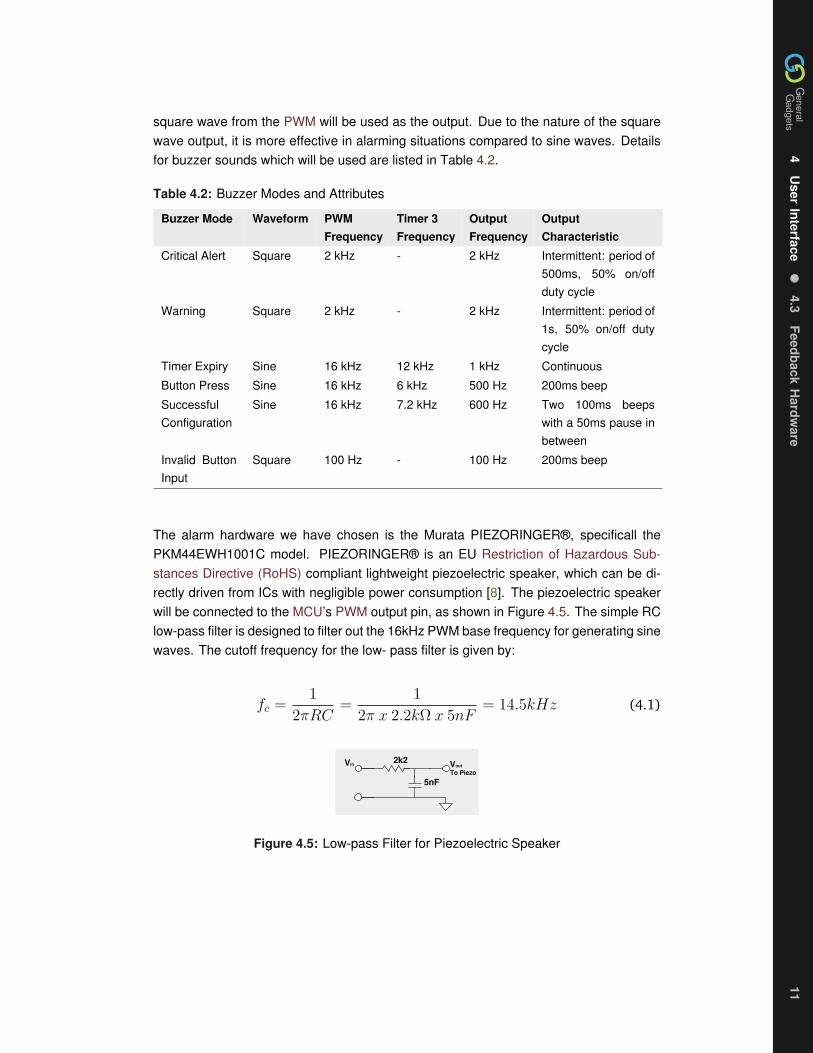
4
User
Interface
43Feedback
Hardw
are11
4
User
Interface
43Feedback
Hardw
are11
4
User
Interface
43Feedback
Hardw
are11
square wave from the PWM will be used as the output Due to the nature of the squarewave output it is more effective in alarming situations compared to sine waves Detailsfor buzzer sounds which will be used are listed in Table 42
Table 42 Buzzer Modes and Attributes
Buzzer Mode Waveform PWMFrequency
Timer 3Frequency
OutputFrequency
OutputCharacteristic
Critical Alert Square 2 kHz - 2 kHz Intermittent period of500ms 50 onoffduty cycle
Warning Square 2 kHz - 2 kHz Intermittent period of1s 50 onoff dutycycle
Timer Expiry Sine 16 kHz 12 kHz 1 kHz Continuous
Button Press Sine 16 kHz 6 kHz 500 Hz 200ms beep
SuccessfulConfiguration
Sine 16 kHz 72 kHz 600 Hz Two 100ms beepswith a 50ms pause inbetween
Invalid ButtonInput
Square 100 Hz - 100 Hz 200ms beep
The alarm hardware we have chosen is the Murata PIEZORINGERreg specificall thePKM44EWH1001C model PIEZORINGERreg is an EU Restriction of Hazardous Sub-stances Directive (RoHS) compliant lightweight piezoelectric speaker which can be di-rectly driven from ICs with negligible power consumption [8] The piezoelectric speakerwill be connected to the MCUrsquos PWM output pin as shown in Figure 45 The simple RClow-pass filter is designed to filter out the 16kHz PWM base frequency for generating sinewaves The cutoff frequency for the low- pass filter is given by
fc =1
2πRC=
1
2π x 22kΩ x 5nF= 145kHz (41)
5nF
2k2 VoutVin
To Piezo
Figure 45 Low-pass Filter for Piezoelectric Speaker
4
Use
rIn
terf
ace
4
4Fe
edba
ckB
ehav
iour
12
4
Use
rIn
terf
ace
4
4Fe
edba
ckB
ehav
iour
12
4
Use
rIn
terf
ace
4
4Fe
edba
ckB
ehav
iour
12
44 Feedback Behaviour
The Kitchen Alert system has the need to communicate s significant amount of informationto the user The onoff status the warning or alert status and the different parameters ofthe different subsystems all must be indicated in a clear and precise manner
To indicate the onoff status of each subsystem green LEDs will be placed behind thebuttons of the corresponding subsystem They will be lit whenever the subsystem is onand unlit when it is off To indicate an alert for a subsystem red LEDs will be placed abovethe subsystemrsquos button by the corresponding symbol The red LEDs will light wheneverthere is an alert from that subsystem
A numeric LED display will be used to display the parameters of the different subsystemsBecause there are both normal and configuration modes for all the subsystems blinkingof the LED display will be used to differentiate the too modes The table below showswhat will be displayed from the subsystems in the different modes
Table 43 Config Display
Subsystem Display Parameter Configuration Display Parameter (blinking)
Clock Time Time
Humidity Current Humidity Humidity Threshold
Temperature Current Temperature Temperature Threshold
Timer Countdown Timer Time to Countdown From
Motion Time Since Last Motion Allowable Time for No Motion
5
TestP
lan13
5
TestP
lan13
5
TestP
lan13
5 Test Plan
To ensure that the system works to specification a test plan along with test cases havebeen created Whenever the system is changed it must be tested against these testcases Each sub-system will have its own separate test case
Test Case 1System ClockTimeDescription Testing the functionality of setting the clock
Step Action Expected Results Pass Fail Comments
1 Turn System On LED Display will blink to setTime
2 Use Arrow Buttons to set cur-rent time When finished re-main inactive for 3 seconds
The Clock will be set and dis-plays current time
3 While in Clock mode pressconfigure button
The Clock will enter Configu-ration mode
4 Set the clock to a new timeusing arrow buttons Whenfinished remain inactive for3 seconds
The Clock will display newtime
Test Case 2System Humidity SensorDescription Testing of turning the humidity sensor on or off and setting the humiditythreshold
Step Action Expected Results Pass Fail Comments
1 When system is on pressthe humidity button Com-pare results with external hu-midity sensor
LED Display will Display cur-rent humidity
2 Press configure button The Status LED for the Hu-midity system will blink
3 Use the arrow buttons andset the humidity threshold to50 When finished remaininactive for 3 seconds
The new threshold will be50 and Status LED willbecome steady
4 Expose the system to smallamount of steam from boilingwater
The FanIndicator will turn ononce the 50 threshold isreached
5
Test
Pla
n14
5
Test
Pla
n14
5
Test
Pla
n14
Step Action Expected Results Pass Fail Comments
5 Press and hold the humiditybutton for 3 seconds
The Humidity system will turnoff and the Status LED willturn off
6 Press and hold the humiditybutton for 3 seconds
The Humidity system will turnon and the Status LED willturn on
Test Case 3System Temperature SensorDescription Testing of turning the Temperature sensor on or off and setting the Tem-perature sensorrsquos threshold
Step Action Expected Results Pass Fail Comments
1 When system is on pressthe Temperature Compareresults with external an ex-ternal thermometer
LED Display will Display cur-rent temperature
2 Press configure button The Status LED for the Tem-perature system will blink
3 Use the arrow buttons andset the Temperature thresh-old to 90degC When finishedremain inactive for 3 sec-onds
The new threshold will be90degC Status LED will be-come steady
4 Boil a pot of water on thestove
The system will set off thealarm and alert the user tocome back to the kitchen
5 Press the Temperature but-ton
The Alarm will turn off for 30seconds
6 Press and hold the Temper-ature button for 3 seconds
The Temperature system willturn off and the Status LEDwill turn off
7 Press and hold the Temper-ature button for 3 seconds
The Temperature system willturn on and the Status LEDwill turn on
5
TestP
lan15
5
TestP
lan15
5
TestP
lan15
Test Case 4System TimerDescription This test case will test the functionality of the timer system
Step Action Expected Results Pass Fail Comments
1 When system is on Pressthe Timer button followed bythe Configure button
The system will enter timerconfiguration setting TheStatus LED for the Timersystem will blink
2 Use the arrow buttons andset the Timer to 30 secondsWhen finished remain inac-tive for 3 seconds
The timer will start countingdown from 30 seconds Sta-tus LED will become steady
3 Press and hold the timer but-ton
The status LED for the Timerwill turn off The counter willstop its count down
4 Press and hold the timer but-ton
The status LED for the Timerwill turn On The counter willcontinue its count down
5 Wait until timer expires The timerrsquos alarm will turn on
Test Case 5System Motion DetectorDescription This test case will test the functionality of the Motion Detector system
Step Action Expected Results Pass Fail Comments
1 When system is on Pressthe Motion detection buttonfollowed by the Configurebutton
The system will enter motionconfiguration setting TheStatus LED for the motionsystem will blink
2 Use the arrow buttons andset the threshold to 10 sec-onds When finished remaininactive for 3 seconds
The motion detectorrsquos timerwill be set to 10 secondsStatus LED will becomesteady
3 Leave the vicinity of the sys-tem for 10 seconds
The system will alert the userto return to the kitchen
4 Return to the system The alert will stop
6
Con
clus
ion
16
6
Con
clus
ion
16
6
Con
clus
ion
16
6 Conclusion
General Gadgets Canada approves the design specifications contained in this report Byoutlining the specific behaviors in the various modes the Kitchen Alert prototype will bebuilt to operate in the desired manner for the different conditions that it will encounter Toverify the behaviors the Kitchen Alert system will be put through the comprehensive andsystematic test plan described in this report Members of the General Gadgets Canadawill frequently reference these specifications during the development schedule The pro-totype for Kitchen Alert is projected for completion in April 2009
R
eferences17
R
eferences17
R
eferences17
References
[1] General Gadgets Canada ldquoFunctional Specs Kitchen Alertrdquo February 2009 Version10
[2] Temperature amp Process Instruments Inc ldquoIRtec Rayomatic 4 Infrared Fixed MountThermometerrdquo [Online] Available httpwwwtnp-instrumentscomrayomatic4_infrared_thermometerhtml
[3] Sure Electronics ldquoPyroelectric Infrared PIR Motion Sensor Detector Module UserGuide DC-SS105_Ver10rdquo
[4] Honeywell ldquoHIH-403031 Series Humidity Sensorsrdquo [Online] Available httpsensinghoneywellcomindexcfmci_id142958la_id1document1re_id0
[5] Quantum Research Group ldquoE1103 Evaluation Assembly User Guiderdquo [Online]Available wwwatmelcomdynresourcesprod_documentsE1103_100pdf
[6] Microchip Technology ldquoPIC18F2525262045254620 Data Sheetrdquo [Online] Avail-able httpww1microchipcomdownloadsenDeviceDoc39626epdf
[7] Lite-on Electronics Inc ldquoLTC-4727JR Data Sheetrdquo [Online] Available httpmediadigikeycompdfData20SheetsLite-On20PDFsLTC-4727JRpdf
[8] Murata Manufacturing Co Ltd ldquoPiezoelectric Sound Componentsrdquo [Online]Available httpwwwmuratacomcatalogp37epdf
A
Sch
emat
ics
18
A
Sch
emat
ics
18
A
Sch
emat
ics
18
A Schematics
LD
DC
DB
DD
DA
PH
BI
VSS
VDD
Of
Og
Oe
Od
Oc
Ob
Oa
HEF4
543B
2k2
2k2
2k2
2k2
2k2
2k2
2k2
Display Board
Main Board
Buttons10
1nF
MCLRRE3
RA0AN0
RA1AN1
RA2AN2
RA3AN3
RA4
RA5
RE0
RE1
RE2
VDD
VSS
OSC1
OSC2
RC0
RC1CCP2
RC2CPP1
RC3SCK
RD0
RD1
RB7PGD
RB6PGC
RB5PGM
RB4
RB3
RB2INT2
RB1INT1
RB0INT0
VDD
VSS
RD7
RD6
RD5
RD4
RC7RX
RC6TX
RC5SDO
RC4SDI
RD3
RD2
PIC
18F4
620
1nF
1nF
ICSP
1nF5V
5V
5V
5V 5V
SPI
HumidityTemperature
piezo2k2
5nF
B0
B1
B2
B3
B4
B5
B6
B7
VDD
VSS
CS
SCK
SI
SO
A7
A6
A5
A4
A3
A2
A1
A0
INTA
INTB
RESET
A2
A1
A0
MCP23
S17
Low-pass
Button Board
1nF
100k
Indi
cato
rs
Indicators
SmokeDetector
MotionDetector
3V
1k8
3V
1k8
CHANGE TX RX
AMPM
RST
Figure A1 System Schematic
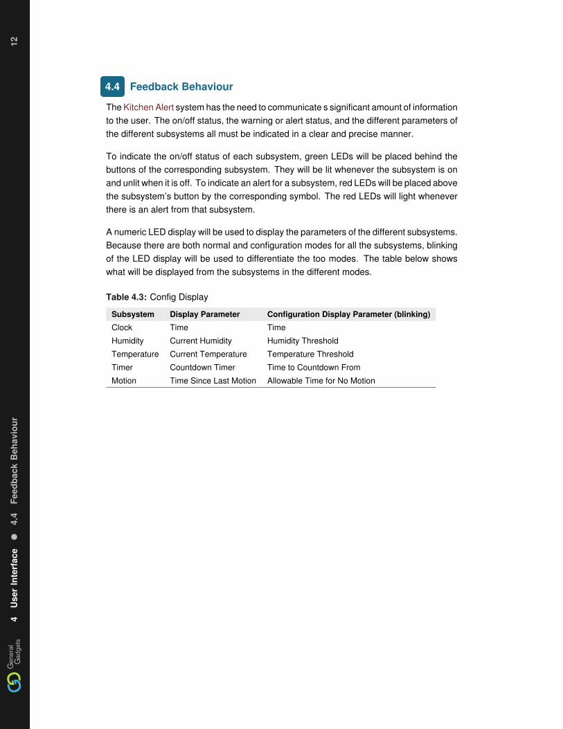
4
Use
rIn
terf
ace
4
4Fe
edba
ckB
ehav
iour
12
4
Use
rIn
terf
ace
4
4Fe
edba
ckB
ehav
iour
12
4
Use
rIn
terf
ace
4
4Fe
edba
ckB
ehav
iour
12
44 Feedback Behaviour
The Kitchen Alert system has the need to communicate s significant amount of informationto the user The onoff status the warning or alert status and the different parameters ofthe different subsystems all must be indicated in a clear and precise manner
To indicate the onoff status of each subsystem green LEDs will be placed behind thebuttons of the corresponding subsystem They will be lit whenever the subsystem is onand unlit when it is off To indicate an alert for a subsystem red LEDs will be placed abovethe subsystemrsquos button by the corresponding symbol The red LEDs will light wheneverthere is an alert from that subsystem
A numeric LED display will be used to display the parameters of the different subsystemsBecause there are both normal and configuration modes for all the subsystems blinkingof the LED display will be used to differentiate the too modes The table below showswhat will be displayed from the subsystems in the different modes
Table 43 Config Display
Subsystem Display Parameter Configuration Display Parameter (blinking)
Clock Time Time
Humidity Current Humidity Humidity Threshold
Temperature Current Temperature Temperature Threshold
Timer Countdown Timer Time to Countdown From
Motion Time Since Last Motion Allowable Time for No Motion
5
TestP
lan13
5
TestP
lan13
5
TestP
lan13
5 Test Plan
To ensure that the system works to specification a test plan along with test cases havebeen created Whenever the system is changed it must be tested against these testcases Each sub-system will have its own separate test case
Test Case 1System ClockTimeDescription Testing the functionality of setting the clock
Step Action Expected Results Pass Fail Comments
1 Turn System On LED Display will blink to setTime
2 Use Arrow Buttons to set cur-rent time When finished re-main inactive for 3 seconds
The Clock will be set and dis-plays current time
3 While in Clock mode pressconfigure button
The Clock will enter Configu-ration mode
4 Set the clock to a new timeusing arrow buttons Whenfinished remain inactive for3 seconds
The Clock will display newtime
Test Case 2System Humidity SensorDescription Testing of turning the humidity sensor on or off and setting the humiditythreshold
Step Action Expected Results Pass Fail Comments
1 When system is on pressthe humidity button Com-pare results with external hu-midity sensor
LED Display will Display cur-rent humidity
2 Press configure button The Status LED for the Hu-midity system will blink
3 Use the arrow buttons andset the humidity threshold to50 When finished remaininactive for 3 seconds
The new threshold will be50 and Status LED willbecome steady
4 Expose the system to smallamount of steam from boilingwater
The FanIndicator will turn ononce the 50 threshold isreached
5
Test
Pla
n14
5
Test
Pla
n14
5
Test
Pla
n14
Step Action Expected Results Pass Fail Comments
5 Press and hold the humiditybutton for 3 seconds
The Humidity system will turnoff and the Status LED willturn off
6 Press and hold the humiditybutton for 3 seconds
The Humidity system will turnon and the Status LED willturn on
Test Case 3System Temperature SensorDescription Testing of turning the Temperature sensor on or off and setting the Tem-perature sensorrsquos threshold
Step Action Expected Results Pass Fail Comments
1 When system is on pressthe Temperature Compareresults with external an ex-ternal thermometer
LED Display will Display cur-rent temperature
2 Press configure button The Status LED for the Tem-perature system will blink
3 Use the arrow buttons andset the Temperature thresh-old to 90degC When finishedremain inactive for 3 sec-onds
The new threshold will be90degC Status LED will be-come steady
4 Boil a pot of water on thestove
The system will set off thealarm and alert the user tocome back to the kitchen
5 Press the Temperature but-ton
The Alarm will turn off for 30seconds
6 Press and hold the Temper-ature button for 3 seconds
The Temperature system willturn off and the Status LEDwill turn off
7 Press and hold the Temper-ature button for 3 seconds
The Temperature system willturn on and the Status LEDwill turn on
5
TestP
lan15
5
TestP
lan15
5
TestP
lan15
Test Case 4System TimerDescription This test case will test the functionality of the timer system
Step Action Expected Results Pass Fail Comments
1 When system is on Pressthe Timer button followed bythe Configure button
The system will enter timerconfiguration setting TheStatus LED for the Timersystem will blink
2 Use the arrow buttons andset the Timer to 30 secondsWhen finished remain inac-tive for 3 seconds
The timer will start countingdown from 30 seconds Sta-tus LED will become steady
3 Press and hold the timer but-ton
The status LED for the Timerwill turn off The counter willstop its count down
4 Press and hold the timer but-ton
The status LED for the Timerwill turn On The counter willcontinue its count down
5 Wait until timer expires The timerrsquos alarm will turn on
Test Case 5System Motion DetectorDescription This test case will test the functionality of the Motion Detector system
Step Action Expected Results Pass Fail Comments
1 When system is on Pressthe Motion detection buttonfollowed by the Configurebutton
The system will enter motionconfiguration setting TheStatus LED for the motionsystem will blink
2 Use the arrow buttons andset the threshold to 10 sec-onds When finished remaininactive for 3 seconds
The motion detectorrsquos timerwill be set to 10 secondsStatus LED will becomesteady
3 Leave the vicinity of the sys-tem for 10 seconds
The system will alert the userto return to the kitchen
4 Return to the system The alert will stop
6
Con
clus
ion
16
6
Con
clus
ion
16
6
Con
clus
ion
16
6 Conclusion
General Gadgets Canada approves the design specifications contained in this report Byoutlining the specific behaviors in the various modes the Kitchen Alert prototype will bebuilt to operate in the desired manner for the different conditions that it will encounter Toverify the behaviors the Kitchen Alert system will be put through the comprehensive andsystematic test plan described in this report Members of the General Gadgets Canadawill frequently reference these specifications during the development schedule The pro-totype for Kitchen Alert is projected for completion in April 2009
R
eferences17
R
eferences17
R
eferences17
References
[1] General Gadgets Canada ldquoFunctional Specs Kitchen Alertrdquo February 2009 Version10
[2] Temperature amp Process Instruments Inc ldquoIRtec Rayomatic 4 Infrared Fixed MountThermometerrdquo [Online] Available httpwwwtnp-instrumentscomrayomatic4_infrared_thermometerhtml
[3] Sure Electronics ldquoPyroelectric Infrared PIR Motion Sensor Detector Module UserGuide DC-SS105_Ver10rdquo
[4] Honeywell ldquoHIH-403031 Series Humidity Sensorsrdquo [Online] Available httpsensinghoneywellcomindexcfmci_id142958la_id1document1re_id0
[5] Quantum Research Group ldquoE1103 Evaluation Assembly User Guiderdquo [Online]Available wwwatmelcomdynresourcesprod_documentsE1103_100pdf
[6] Microchip Technology ldquoPIC18F2525262045254620 Data Sheetrdquo [Online] Avail-able httpww1microchipcomdownloadsenDeviceDoc39626epdf
[7] Lite-on Electronics Inc ldquoLTC-4727JR Data Sheetrdquo [Online] Available httpmediadigikeycompdfData20SheetsLite-On20PDFsLTC-4727JRpdf
[8] Murata Manufacturing Co Ltd ldquoPiezoelectric Sound Componentsrdquo [Online]Available httpwwwmuratacomcatalogp37epdf
A
Sch
emat
ics
18
A
Sch
emat
ics
18
A
Sch
emat
ics
18
A Schematics
LD
DC
DB
DD
DA
PH
BI
VSS
VDD
Of
Og
Oe
Od
Oc
Ob
Oa
HEF4
543B
2k2
2k2
2k2
2k2
2k2
2k2
2k2
Display Board
Main Board
Buttons10
1nF
MCLRRE3
RA0AN0
RA1AN1
RA2AN2
RA3AN3
RA4
RA5
RE0
RE1
RE2
VDD
VSS
OSC1
OSC2
RC0
RC1CCP2
RC2CPP1
RC3SCK
RD0
RD1
RB7PGD
RB6PGC
RB5PGM
RB4
RB3
RB2INT2
RB1INT1
RB0INT0
VDD
VSS
RD7
RD6
RD5
RD4
RC7RX
RC6TX
RC5SDO
RC4SDI
RD3
RD2
PIC
18F4
620
1nF
1nF
ICSP
1nF5V
5V
5V
5V 5V
SPI
HumidityTemperature
piezo2k2
5nF
B0
B1
B2
B3
B4
B5
B6
B7
VDD
VSS
CS
SCK
SI
SO
A7
A6
A5
A4
A3
A2
A1
A0
INTA
INTB
RESET
A2
A1
A0
MCP23
S17
Low-pass
Button Board
1nF
100k
Indi
cato
rs
Indicators
SmokeDetector
MotionDetector
3V
1k8
3V
1k8
CHANGE TX RX
AMPM
RST
Figure A1 System Schematic

5
TestP
lan13
5
TestP
lan13
5
TestP
lan13
5 Test Plan
To ensure that the system works to specification a test plan along with test cases havebeen created Whenever the system is changed it must be tested against these testcases Each sub-system will have its own separate test case
Test Case 1System ClockTimeDescription Testing the functionality of setting the clock
Step Action Expected Results Pass Fail Comments
1 Turn System On LED Display will blink to setTime
2 Use Arrow Buttons to set cur-rent time When finished re-main inactive for 3 seconds
The Clock will be set and dis-plays current time
3 While in Clock mode pressconfigure button
The Clock will enter Configu-ration mode
4 Set the clock to a new timeusing arrow buttons Whenfinished remain inactive for3 seconds
The Clock will display newtime
Test Case 2System Humidity SensorDescription Testing of turning the humidity sensor on or off and setting the humiditythreshold
Step Action Expected Results Pass Fail Comments
1 When system is on pressthe humidity button Com-pare results with external hu-midity sensor
LED Display will Display cur-rent humidity
2 Press configure button The Status LED for the Hu-midity system will blink
3 Use the arrow buttons andset the humidity threshold to50 When finished remaininactive for 3 seconds
The new threshold will be50 and Status LED willbecome steady
4 Expose the system to smallamount of steam from boilingwater
The FanIndicator will turn ononce the 50 threshold isreached
5
Test
Pla
n14
5
Test
Pla
n14
5
Test
Pla
n14
Step Action Expected Results Pass Fail Comments
5 Press and hold the humiditybutton for 3 seconds
The Humidity system will turnoff and the Status LED willturn off
6 Press and hold the humiditybutton for 3 seconds
The Humidity system will turnon and the Status LED willturn on
Test Case 3System Temperature SensorDescription Testing of turning the Temperature sensor on or off and setting the Tem-perature sensorrsquos threshold
Step Action Expected Results Pass Fail Comments
1 When system is on pressthe Temperature Compareresults with external an ex-ternal thermometer
LED Display will Display cur-rent temperature
2 Press configure button The Status LED for the Tem-perature system will blink
3 Use the arrow buttons andset the Temperature thresh-old to 90degC When finishedremain inactive for 3 sec-onds
The new threshold will be90degC Status LED will be-come steady
4 Boil a pot of water on thestove
The system will set off thealarm and alert the user tocome back to the kitchen
5 Press the Temperature but-ton
The Alarm will turn off for 30seconds
6 Press and hold the Temper-ature button for 3 seconds
The Temperature system willturn off and the Status LEDwill turn off
7 Press and hold the Temper-ature button for 3 seconds
The Temperature system willturn on and the Status LEDwill turn on
5
TestP
lan15
5
TestP
lan15
5
TestP
lan15
Test Case 4System TimerDescription This test case will test the functionality of the timer system
Step Action Expected Results Pass Fail Comments
1 When system is on Pressthe Timer button followed bythe Configure button
The system will enter timerconfiguration setting TheStatus LED for the Timersystem will blink
2 Use the arrow buttons andset the Timer to 30 secondsWhen finished remain inac-tive for 3 seconds
The timer will start countingdown from 30 seconds Sta-tus LED will become steady
3 Press and hold the timer but-ton
The status LED for the Timerwill turn off The counter willstop its count down
4 Press and hold the timer but-ton
The status LED for the Timerwill turn On The counter willcontinue its count down
5 Wait until timer expires The timerrsquos alarm will turn on
Test Case 5System Motion DetectorDescription This test case will test the functionality of the Motion Detector system
Step Action Expected Results Pass Fail Comments
1 When system is on Pressthe Motion detection buttonfollowed by the Configurebutton
The system will enter motionconfiguration setting TheStatus LED for the motionsystem will blink
2 Use the arrow buttons andset the threshold to 10 sec-onds When finished remaininactive for 3 seconds
The motion detectorrsquos timerwill be set to 10 secondsStatus LED will becomesteady
3 Leave the vicinity of the sys-tem for 10 seconds
The system will alert the userto return to the kitchen
4 Return to the system The alert will stop
6
Con
clus
ion
16
6
Con
clus
ion
16
6
Con
clus
ion
16
6 Conclusion
General Gadgets Canada approves the design specifications contained in this report Byoutlining the specific behaviors in the various modes the Kitchen Alert prototype will bebuilt to operate in the desired manner for the different conditions that it will encounter Toverify the behaviors the Kitchen Alert system will be put through the comprehensive andsystematic test plan described in this report Members of the General Gadgets Canadawill frequently reference these specifications during the development schedule The pro-totype for Kitchen Alert is projected for completion in April 2009
R
eferences17
R
eferences17
R
eferences17
References
[1] General Gadgets Canada ldquoFunctional Specs Kitchen Alertrdquo February 2009 Version10
[2] Temperature amp Process Instruments Inc ldquoIRtec Rayomatic 4 Infrared Fixed MountThermometerrdquo [Online] Available httpwwwtnp-instrumentscomrayomatic4_infrared_thermometerhtml
[3] Sure Electronics ldquoPyroelectric Infrared PIR Motion Sensor Detector Module UserGuide DC-SS105_Ver10rdquo
[4] Honeywell ldquoHIH-403031 Series Humidity Sensorsrdquo [Online] Available httpsensinghoneywellcomindexcfmci_id142958la_id1document1re_id0
[5] Quantum Research Group ldquoE1103 Evaluation Assembly User Guiderdquo [Online]Available wwwatmelcomdynresourcesprod_documentsE1103_100pdf
[6] Microchip Technology ldquoPIC18F2525262045254620 Data Sheetrdquo [Online] Avail-able httpww1microchipcomdownloadsenDeviceDoc39626epdf
[7] Lite-on Electronics Inc ldquoLTC-4727JR Data Sheetrdquo [Online] Available httpmediadigikeycompdfData20SheetsLite-On20PDFsLTC-4727JRpdf
[8] Murata Manufacturing Co Ltd ldquoPiezoelectric Sound Componentsrdquo [Online]Available httpwwwmuratacomcatalogp37epdf
A
Sch
emat
ics
18
A
Sch
emat
ics
18
A
Sch
emat
ics
18
A Schematics
LD
DC
DB
DD
DA
PH
BI
VSS
VDD
Of
Og
Oe
Od
Oc
Ob
Oa
HEF4
543B
2k2
2k2
2k2
2k2
2k2
2k2
2k2
Display Board
Main Board
Buttons10
1nF
MCLRRE3
RA0AN0
RA1AN1
RA2AN2
RA3AN3
RA4
RA5
RE0
RE1
RE2
VDD
VSS
OSC1
OSC2
RC0
RC1CCP2
RC2CPP1
RC3SCK
RD0
RD1
RB7PGD
RB6PGC
RB5PGM
RB4
RB3
RB2INT2
RB1INT1
RB0INT0
VDD
VSS
RD7
RD6
RD5
RD4
RC7RX
RC6TX
RC5SDO
RC4SDI
RD3
RD2
PIC
18F4
620
1nF
1nF
ICSP
1nF5V
5V
5V
5V 5V
SPI
HumidityTemperature
piezo2k2
5nF
B0
B1
B2
B3
B4
B5
B6
B7
VDD
VSS
CS
SCK
SI
SO
A7
A6
A5
A4
A3
A2
A1
A0
INTA
INTB
RESET
A2
A1
A0
MCP23
S17
Low-pass
Button Board
1nF
100k
Indi
cato
rs
Indicators
SmokeDetector
MotionDetector
3V
1k8
3V
1k8
CHANGE TX RX
AMPM
RST
Figure A1 System Schematic

5
Test
Pla
n14
5
Test
Pla
n14
5
Test
Pla
n14
Step Action Expected Results Pass Fail Comments
5 Press and hold the humiditybutton for 3 seconds
The Humidity system will turnoff and the Status LED willturn off
6 Press and hold the humiditybutton for 3 seconds
The Humidity system will turnon and the Status LED willturn on
Test Case 3System Temperature SensorDescription Testing of turning the Temperature sensor on or off and setting the Tem-perature sensorrsquos threshold
Step Action Expected Results Pass Fail Comments
1 When system is on pressthe Temperature Compareresults with external an ex-ternal thermometer
LED Display will Display cur-rent temperature
2 Press configure button The Status LED for the Tem-perature system will blink
3 Use the arrow buttons andset the Temperature thresh-old to 90degC When finishedremain inactive for 3 sec-onds
The new threshold will be90degC Status LED will be-come steady
4 Boil a pot of water on thestove
The system will set off thealarm and alert the user tocome back to the kitchen
5 Press the Temperature but-ton
The Alarm will turn off for 30seconds
6 Press and hold the Temper-ature button for 3 seconds
The Temperature system willturn off and the Status LEDwill turn off
7 Press and hold the Temper-ature button for 3 seconds
The Temperature system willturn on and the Status LEDwill turn on
5
TestP
lan15
5
TestP
lan15
5
TestP
lan15
Test Case 4System TimerDescription This test case will test the functionality of the timer system
Step Action Expected Results Pass Fail Comments
1 When system is on Pressthe Timer button followed bythe Configure button
The system will enter timerconfiguration setting TheStatus LED for the Timersystem will blink
2 Use the arrow buttons andset the Timer to 30 secondsWhen finished remain inac-tive for 3 seconds
The timer will start countingdown from 30 seconds Sta-tus LED will become steady
3 Press and hold the timer but-ton
The status LED for the Timerwill turn off The counter willstop its count down
4 Press and hold the timer but-ton
The status LED for the Timerwill turn On The counter willcontinue its count down
5 Wait until timer expires The timerrsquos alarm will turn on
Test Case 5System Motion DetectorDescription This test case will test the functionality of the Motion Detector system
Step Action Expected Results Pass Fail Comments
1 When system is on Pressthe Motion detection buttonfollowed by the Configurebutton
The system will enter motionconfiguration setting TheStatus LED for the motionsystem will blink
2 Use the arrow buttons andset the threshold to 10 sec-onds When finished remaininactive for 3 seconds
The motion detectorrsquos timerwill be set to 10 secondsStatus LED will becomesteady
3 Leave the vicinity of the sys-tem for 10 seconds
The system will alert the userto return to the kitchen
4 Return to the system The alert will stop
6
Con
clus
ion
16
6
Con
clus
ion
16
6
Con
clus
ion
16
6 Conclusion
General Gadgets Canada approves the design specifications contained in this report Byoutlining the specific behaviors in the various modes the Kitchen Alert prototype will bebuilt to operate in the desired manner for the different conditions that it will encounter Toverify the behaviors the Kitchen Alert system will be put through the comprehensive andsystematic test plan described in this report Members of the General Gadgets Canadawill frequently reference these specifications during the development schedule The pro-totype for Kitchen Alert is projected for completion in April 2009
R
eferences17
R
eferences17
R
eferences17
References
[1] General Gadgets Canada ldquoFunctional Specs Kitchen Alertrdquo February 2009 Version10
[2] Temperature amp Process Instruments Inc ldquoIRtec Rayomatic 4 Infrared Fixed MountThermometerrdquo [Online] Available httpwwwtnp-instrumentscomrayomatic4_infrared_thermometerhtml
[3] Sure Electronics ldquoPyroelectric Infrared PIR Motion Sensor Detector Module UserGuide DC-SS105_Ver10rdquo
[4] Honeywell ldquoHIH-403031 Series Humidity Sensorsrdquo [Online] Available httpsensinghoneywellcomindexcfmci_id142958la_id1document1re_id0
[5] Quantum Research Group ldquoE1103 Evaluation Assembly User Guiderdquo [Online]Available wwwatmelcomdynresourcesprod_documentsE1103_100pdf
[6] Microchip Technology ldquoPIC18F2525262045254620 Data Sheetrdquo [Online] Avail-able httpww1microchipcomdownloadsenDeviceDoc39626epdf
[7] Lite-on Electronics Inc ldquoLTC-4727JR Data Sheetrdquo [Online] Available httpmediadigikeycompdfData20SheetsLite-On20PDFsLTC-4727JRpdf
[8] Murata Manufacturing Co Ltd ldquoPiezoelectric Sound Componentsrdquo [Online]Available httpwwwmuratacomcatalogp37epdf
A
Sch
emat
ics
18
A
Sch
emat
ics
18
A
Sch
emat
ics
18
A Schematics
LD
DC
DB
DD
DA
PH
BI
VSS
VDD
Of
Og
Oe
Od
Oc
Ob
Oa
HEF4
543B
2k2
2k2
2k2
2k2
2k2
2k2
2k2
Display Board
Main Board
Buttons10
1nF
MCLRRE3
RA0AN0
RA1AN1
RA2AN2
RA3AN3
RA4
RA5
RE0
RE1
RE2
VDD
VSS
OSC1
OSC2
RC0
RC1CCP2
RC2CPP1
RC3SCK
RD0
RD1
RB7PGD
RB6PGC
RB5PGM
RB4
RB3
RB2INT2
RB1INT1
RB0INT0
VDD
VSS
RD7
RD6
RD5
RD4
RC7RX
RC6TX
RC5SDO
RC4SDI
RD3
RD2
PIC
18F4
620
1nF
1nF
ICSP
1nF5V
5V
5V
5V 5V
SPI
HumidityTemperature
piezo2k2
5nF
B0
B1
B2
B3
B4
B5
B6
B7
VDD
VSS
CS
SCK
SI
SO
A7
A6
A5
A4
A3
A2
A1
A0
INTA
INTB
RESET
A2
A1
A0
MCP23
S17
Low-pass
Button Board
1nF
100k
Indi
cato
rs
Indicators
SmokeDetector
MotionDetector
3V
1k8
3V
1k8
CHANGE TX RX
AMPM
RST
Figure A1 System Schematic

5
TestP
lan15
5
TestP
lan15
5
TestP
lan15
Test Case 4System TimerDescription This test case will test the functionality of the timer system
Step Action Expected Results Pass Fail Comments
1 When system is on Pressthe Timer button followed bythe Configure button
The system will enter timerconfiguration setting TheStatus LED for the Timersystem will blink
2 Use the arrow buttons andset the Timer to 30 secondsWhen finished remain inac-tive for 3 seconds
The timer will start countingdown from 30 seconds Sta-tus LED will become steady
3 Press and hold the timer but-ton
The status LED for the Timerwill turn off The counter willstop its count down
4 Press and hold the timer but-ton
The status LED for the Timerwill turn On The counter willcontinue its count down
5 Wait until timer expires The timerrsquos alarm will turn on
Test Case 5System Motion DetectorDescription This test case will test the functionality of the Motion Detector system
Step Action Expected Results Pass Fail Comments
1 When system is on Pressthe Motion detection buttonfollowed by the Configurebutton
The system will enter motionconfiguration setting TheStatus LED for the motionsystem will blink
2 Use the arrow buttons andset the threshold to 10 sec-onds When finished remaininactive for 3 seconds
The motion detectorrsquos timerwill be set to 10 secondsStatus LED will becomesteady
3 Leave the vicinity of the sys-tem for 10 seconds
The system will alert the userto return to the kitchen
4 Return to the system The alert will stop
6
Con
clus
ion
16
6
Con
clus
ion
16
6
Con
clus
ion
16
6 Conclusion
General Gadgets Canada approves the design specifications contained in this report Byoutlining the specific behaviors in the various modes the Kitchen Alert prototype will bebuilt to operate in the desired manner for the different conditions that it will encounter Toverify the behaviors the Kitchen Alert system will be put through the comprehensive andsystematic test plan described in this report Members of the General Gadgets Canadawill frequently reference these specifications during the development schedule The pro-totype for Kitchen Alert is projected for completion in April 2009
R
eferences17
R
eferences17
R
eferences17
References
[1] General Gadgets Canada ldquoFunctional Specs Kitchen Alertrdquo February 2009 Version10
[2] Temperature amp Process Instruments Inc ldquoIRtec Rayomatic 4 Infrared Fixed MountThermometerrdquo [Online] Available httpwwwtnp-instrumentscomrayomatic4_infrared_thermometerhtml
[3] Sure Electronics ldquoPyroelectric Infrared PIR Motion Sensor Detector Module UserGuide DC-SS105_Ver10rdquo
[4] Honeywell ldquoHIH-403031 Series Humidity Sensorsrdquo [Online] Available httpsensinghoneywellcomindexcfmci_id142958la_id1document1re_id0
[5] Quantum Research Group ldquoE1103 Evaluation Assembly User Guiderdquo [Online]Available wwwatmelcomdynresourcesprod_documentsE1103_100pdf
[6] Microchip Technology ldquoPIC18F2525262045254620 Data Sheetrdquo [Online] Avail-able httpww1microchipcomdownloadsenDeviceDoc39626epdf
[7] Lite-on Electronics Inc ldquoLTC-4727JR Data Sheetrdquo [Online] Available httpmediadigikeycompdfData20SheetsLite-On20PDFsLTC-4727JRpdf
[8] Murata Manufacturing Co Ltd ldquoPiezoelectric Sound Componentsrdquo [Online]Available httpwwwmuratacomcatalogp37epdf
A
Sch
emat
ics
18
A
Sch
emat
ics
18
A
Sch
emat
ics
18
A Schematics
LD
DC
DB
DD
DA
PH
BI
VSS
VDD
Of
Og
Oe
Od
Oc
Ob
Oa
HEF4
543B
2k2
2k2
2k2
2k2
2k2
2k2
2k2
Display Board
Main Board
Buttons10
1nF
MCLRRE3
RA0AN0
RA1AN1
RA2AN2
RA3AN3
RA4
RA5
RE0
RE1
RE2
VDD
VSS
OSC1
OSC2
RC0
RC1CCP2
RC2CPP1
RC3SCK
RD0
RD1
RB7PGD
RB6PGC
RB5PGM
RB4
RB3
RB2INT2
RB1INT1
RB0INT0
VDD
VSS
RD7
RD6
RD5
RD4
RC7RX
RC6TX
RC5SDO
RC4SDI
RD3
RD2
PIC
18F4
620
1nF
1nF
ICSP
1nF5V
5V
5V
5V 5V
SPI
HumidityTemperature
piezo2k2
5nF
B0
B1
B2
B3
B4
B5
B6
B7
VDD
VSS
CS
SCK
SI
SO
A7
A6
A5
A4
A3
A2
A1
A0
INTA
INTB
RESET
A2
A1
A0
MCP23
S17
Low-pass
Button Board
1nF
100k
Indi
cato
rs
Indicators
SmokeDetector
MotionDetector
3V
1k8
3V
1k8
CHANGE TX RX
AMPM
RST
Figure A1 System Schematic

6
Con
clus
ion
16
6
Con
clus
ion
16
6
Con
clus
ion
16
6 Conclusion
General Gadgets Canada approves the design specifications contained in this report Byoutlining the specific behaviors in the various modes the Kitchen Alert prototype will bebuilt to operate in the desired manner for the different conditions that it will encounter Toverify the behaviors the Kitchen Alert system will be put through the comprehensive andsystematic test plan described in this report Members of the General Gadgets Canadawill frequently reference these specifications during the development schedule The pro-totype for Kitchen Alert is projected for completion in April 2009
R
eferences17
R
eferences17
R
eferences17
References
[1] General Gadgets Canada ldquoFunctional Specs Kitchen Alertrdquo February 2009 Version10
[2] Temperature amp Process Instruments Inc ldquoIRtec Rayomatic 4 Infrared Fixed MountThermometerrdquo [Online] Available httpwwwtnp-instrumentscomrayomatic4_infrared_thermometerhtml
[3] Sure Electronics ldquoPyroelectric Infrared PIR Motion Sensor Detector Module UserGuide DC-SS105_Ver10rdquo
[4] Honeywell ldquoHIH-403031 Series Humidity Sensorsrdquo [Online] Available httpsensinghoneywellcomindexcfmci_id142958la_id1document1re_id0
[5] Quantum Research Group ldquoE1103 Evaluation Assembly User Guiderdquo [Online]Available wwwatmelcomdynresourcesprod_documentsE1103_100pdf
[6] Microchip Technology ldquoPIC18F2525262045254620 Data Sheetrdquo [Online] Avail-able httpww1microchipcomdownloadsenDeviceDoc39626epdf
[7] Lite-on Electronics Inc ldquoLTC-4727JR Data Sheetrdquo [Online] Available httpmediadigikeycompdfData20SheetsLite-On20PDFsLTC-4727JRpdf
[8] Murata Manufacturing Co Ltd ldquoPiezoelectric Sound Componentsrdquo [Online]Available httpwwwmuratacomcatalogp37epdf
A
Sch
emat
ics
18
A
Sch
emat
ics
18
A
Sch
emat
ics
18
A Schematics
LD
DC
DB
DD
DA
PH
BI
VSS
VDD
Of
Og
Oe
Od
Oc
Ob
Oa
HEF4
543B
2k2
2k2
2k2
2k2
2k2
2k2
2k2
Display Board
Main Board
Buttons10
1nF
MCLRRE3
RA0AN0
RA1AN1
RA2AN2
RA3AN3
RA4
RA5
RE0
RE1
RE2
VDD
VSS
OSC1
OSC2
RC0
RC1CCP2
RC2CPP1
RC3SCK
RD0
RD1
RB7PGD
RB6PGC
RB5PGM
RB4
RB3
RB2INT2
RB1INT1
RB0INT0
VDD
VSS
RD7
RD6
RD5
RD4
RC7RX
RC6TX
RC5SDO
RC4SDI
RD3
RD2
PIC
18F4
620
1nF
1nF
ICSP
1nF5V
5V
5V
5V 5V
SPI
HumidityTemperature
piezo2k2
5nF
B0
B1
B2
B3
B4
B5
B6
B7
VDD
VSS
CS
SCK
SI
SO
A7
A6
A5
A4
A3
A2
A1
A0
INTA
INTB
RESET
A2
A1
A0
MCP23
S17
Low-pass
Button Board
1nF
100k
Indi
cato
rs
Indicators
SmokeDetector
MotionDetector
3V
1k8
3V
1k8
CHANGE TX RX
AMPM
RST
Figure A1 System Schematic

R
eferences17
R
eferences17
R
eferences17
References
[1] General Gadgets Canada ldquoFunctional Specs Kitchen Alertrdquo February 2009 Version10
[2] Temperature amp Process Instruments Inc ldquoIRtec Rayomatic 4 Infrared Fixed MountThermometerrdquo [Online] Available httpwwwtnp-instrumentscomrayomatic4_infrared_thermometerhtml
[3] Sure Electronics ldquoPyroelectric Infrared PIR Motion Sensor Detector Module UserGuide DC-SS105_Ver10rdquo
[4] Honeywell ldquoHIH-403031 Series Humidity Sensorsrdquo [Online] Available httpsensinghoneywellcomindexcfmci_id142958la_id1document1re_id0
[5] Quantum Research Group ldquoE1103 Evaluation Assembly User Guiderdquo [Online]Available wwwatmelcomdynresourcesprod_documentsE1103_100pdf
[6] Microchip Technology ldquoPIC18F2525262045254620 Data Sheetrdquo [Online] Avail-able httpww1microchipcomdownloadsenDeviceDoc39626epdf
[7] Lite-on Electronics Inc ldquoLTC-4727JR Data Sheetrdquo [Online] Available httpmediadigikeycompdfData20SheetsLite-On20PDFsLTC-4727JRpdf
[8] Murata Manufacturing Co Ltd ldquoPiezoelectric Sound Componentsrdquo [Online]Available httpwwwmuratacomcatalogp37epdf
A
Sch
emat
ics
18
A
Sch
emat
ics
18
A
Sch
emat
ics
18
A Schematics
LD
DC
DB
DD
DA
PH
BI
VSS
VDD
Of
Og
Oe
Od
Oc
Ob
Oa
HEF4
543B
2k2
2k2
2k2
2k2
2k2
2k2
2k2
Display Board
Main Board
Buttons10
1nF
MCLRRE3
RA0AN0
RA1AN1
RA2AN2
RA3AN3
RA4
RA5
RE0
RE1
RE2
VDD
VSS
OSC1
OSC2
RC0
RC1CCP2
RC2CPP1
RC3SCK
RD0
RD1
RB7PGD
RB6PGC
RB5PGM
RB4
RB3
RB2INT2
RB1INT1
RB0INT0
VDD
VSS
RD7
RD6
RD5
RD4
RC7RX
RC6TX
RC5SDO
RC4SDI
RD3
RD2
PIC
18F4
620
1nF
1nF
ICSP
1nF5V
5V
5V
5V 5V
SPI
HumidityTemperature
piezo2k2
5nF
B0
B1
B2
B3
B4
B5
B6
B7
VDD
VSS
CS
SCK
SI
SO
A7
A6
A5
A4
A3
A2
A1
A0
INTA
INTB
RESET
A2
A1
A0
MCP23
S17
Low-pass
Button Board
1nF
100k
Indi
cato
rs
Indicators
SmokeDetector
MotionDetector
3V
1k8
3V
1k8
CHANGE TX RX
AMPM
RST
Figure A1 System Schematic

A
Sch
emat
ics
18
A
Sch
emat
ics
18
A
Sch
emat
ics
18
A Schematics
LD
DC
DB
DD
DA
PH
BI
VSS
VDD
Of
Og
Oe
Od
Oc
Ob
Oa
HEF4
543B
2k2
2k2
2k2
2k2
2k2
2k2
2k2
Display Board
Main Board
Buttons10
1nF
MCLRRE3
RA0AN0
RA1AN1
RA2AN2
RA3AN3
RA4
RA5
RE0
RE1
RE2
VDD
VSS
OSC1
OSC2
RC0
RC1CCP2
RC2CPP1
RC3SCK
RD0
RD1
RB7PGD
RB6PGC
RB5PGM
RB4
RB3
RB2INT2
RB1INT1
RB0INT0
VDD
VSS
RD7
RD6
RD5
RD4
RC7RX
RC6TX
RC5SDO
RC4SDI
RD3
RD2
PIC
18F4
620
1nF
1nF
ICSP
1nF5V
5V
5V
5V 5V
SPI
HumidityTemperature
piezo2k2
5nF
B0
B1
B2
B3
B4
B5
B6
B7
VDD
VSS
CS
SCK
SI
SO
A7
A6
A5
A4
A3
A2
A1
A0
INTA
INTB
RESET
A2
A1
A0
MCP23
S17
Low-pass
Button Board
1nF
100k
Indi
cato
rs
Indicators
SmokeDetector
MotionDetector
3V
1k8
3V
1k8
CHANGE TX RX
AMPM
RST
Figure A1 System Schematic