Embed Size (px)
Citation preview

National roller brake testing
www.nhvr.gov.au 1 of 24
March 2017

National roller brake testing
www.nhvr.gov.au 2 of 24
Contents 1 Introduction ............................................................................................................................................................ 3 2 Purpose ................................................................................................................................................................... 3 3 Application .............................................................................................................................................................. 3 4 Equipment setup ..................................................................................................................................................... 4
4.1 Test location ................................................................................................................................................. 4 4.2 Setting up at the test location ....................................................................................................................... 4 4.3 Setting up for the test ................................................................................................................................... 4
5 Test procedure – Park and emergency brakes ......................................................................................................... 5 5.1 Emergency brake .......................................................................................................................................... 5 5.2 Park brake..................................................................................................................................................... 5
6 Test procedure – Service brakes .............................................................................................................................. 6 6.1 Conducting the test ....................................................................................................................................... 6
7 Test outcomes ......................................................................................................................................................... 7 8 Acceptance criteria, roadworthiness and defect notices .......................................................................................... 7 9 Vehicle systems requiring additional attention and/or setup .................................................................................. 8 10 Reporting requirements .......................................................................................................................................... 8 Appendix A Approved alternative and supplementary test procedures.............................................................. 9
A.1 Supplementary testing methods. .................................................................................................................. 9 A.2 Vehicles fitted with load sensing valves ........................................................................................................ 9
Appendix B RBT machine specifications and settings ....................................................................................... 10 Appendix C Calibration procedure .................................................................................................................... 11
C.1 The wear and condition of the RBT machine ............................................................................................... 11 C.2 Calibration method ..................................................................................................................................... 11 C.3 Calibration frequency ................................................................................................................................. 12 C.4 Tools used for calibration and their calibration ........................................................................................... 12 C.5 The skill level of the maintainers ................................................................................................................ 12 C.6 Calibration and maintenance records ......................................................................................................... 12
Appendix D RBT machines operator qualifications ........................................................................................... 13 Appendix E Test validation and control ............................................................................................................ 14
E.1 Setup on the rollers .................................................................................................................................... 14 E.2 Applying the brake ...................................................................................................................................... 14 E.3 Air pressure and supply .............................................................................................................................. 14 E.4 Factors affecting brake force that can be measured ................................................................................... 15
Appendix F RBT machine decision trees ........................................................................................................... 16 F.1 Service brake test overview - RBT machine decision tree............................................................................ 16 F.2 Service brake test - RBT machine decision tree ........................................................................................... 17 F.3 Service brake test - RBT machine decision tree ........................................................................................... 18 F.4 Brake balance service brake - RBT machine decision tree ........................................................................... 19 F.5 Park brake test - RBT machine decision tree ............................................................................................... 20
Appendix G RBT operator decision trees .......................................................................................................... 21 G.1 Service brake – User decision tree 1............................................................................................................ 21 G.2 Service brake – User decision tree 2............................................................................................................ 22
Appendix H Vehicle brake testing results report printout ................................................................................. 23 Appendix I User interface ................................................................................................................................ 24
I.1 Service brake high dynamic out of limit ...................................................................................................... 24 I.2 Service brake low brake force measured .................................................................................................... 24
© Copyright National Heavy Vehicle Regulator 2017 creativecommons.org/licenses/by-sa/3.0/au

National roller brake testing
www.nhvr.gov.au 3 of 24
1 Introduction A vehicle’s (including vehicles in a combination’s) ability to brake effectively and efficiently is critical to the safe operation of the vehicle on roads. Given the importance of a vehicle’s brakes, regulators, operators, drivers and the community have an interest in ensuring rigorous processes are in place to verify brake performance.
While it is widely accepted that a full Australian Design Rule (ADR) brake test (fully laden test conducted from 100km/h) is the highest standard test, conducting these tests for maintenance and on-road compliance purposes is not practical. Taking the location, time and safety limitations of the roadside or workshop into account, regulators and industry use other brake testing methods. These other testing methods provide an indication of brake performance, such as decelerometer testing at lower speeds or testing such as skid plate testing or roller brake testing (RBT) that use equipment and technology to simulate an on-road test. Collectively, these test methods are referred to as in-service brake tests.
This RBT procedure, like all in-service brake tests, is not an absolute indicator of brake performance. In-service brake tests are screening tools used to verify that a vehicle’s braking system is functioning and to provide information that highlights potential issues relating to non-compliances and/or system performance. This information can be used to determine if repair or adjustments are required and/or if inspection of specific brake components is required.
In-service brake tests conducted on an unladen or a lightly laden vehicle only provide an indication of the vehicle’s braking performance in the configuration it was tested. Where there are changes to the vehicle’s configuration, such as increased loading, changed load distribution or varied combination configuration, further in-service testing would be required in the new configuration. Testing a vehicle, fully loaded or equivalent (simulated load) is the only test level that assures that brake force is sufficient for all other loading conditions.
Although this procedure does not mandate fully loaded or equivalent (simulated load) testing, these testing conditions are encouraged where it is safe to do so and the facilities are available.
2 Purpose The purpose of this document is to provide a single national standard for the equipment and test procedure used to conduct an RBT of heavy vehicles.
3 Application This procedure This procedure must be used when conducting an RBT: • for compliance or enforcement purposes • during a regulated inspection of a heavy vehicle.
The person conducting an RBT The person conducting an RBT for compliance or enforcement purposes must: • be skilled in RBT use, and • meet the skill level detailed in Appendix D or be under the supervision and instruction of a person who does.
Equipment used for compliance or enforcement The equipment used for RBT must: • meet the specification detailed in Appendix B • be calibrated in accordance with the procedure detailed in Appendix C.
Routine maintenance This procedure may be used when conducting an RBT: • as part of routine maintenance to show that the vehicle will pass this simplified and generalised in-service brake test.
Note: When designing a maintenance regime an operator should consider the maintenance objectives and ensure the brake testing and inspection standards they adopt is consistent with their maintenance objectives. The use of a simplified and generalised type test, such as that outlined in this procedure, may not have sufficient rigor for the intended outcomes of a maintenance management system.

National roller brake testing
www.nhvr.gov.au 4 of 24
4 Equipment setup 4.1 Test location RBT must be conducted on a flat and level surface that is of sufficient length for the entire vehicle to maintain a stationary position with the brakes released. This applies to both the approach to the RBT machine and the departure.
Note: This does not preclude the use of portable RBT machines that use approach and departure ramps.
4.2 Setting up at the test location The RBT machine should be mounted flat and level within the manufacturer’s tolerance, but not greater than a grade of ±1° longitudinally and transversely is recommended. However, up to a grade of ±2° longitudinally and transversely is permitted provided wheel-chocks are used to hold the vehicle in place. Prior to operation and before any vehicle is positioned for testing, the RBT machine should be powered up and all its parameters checked using the manufacturer’s self-checking facility or other protocol. Any fault code displayed during this self-check should be recorded and the RBT machine must not be used until the fault identified is corrected.
Safety note: • The test location must be well ventilated so that the exhaust fumes do not pose a safety risk. • Where there is a likelihood of the vehicle moving when the brakes are not applied, use wheel-chocks to hold the vehicle in
place.
4.3 Setting up for the test When commencing each testing session, the RBT equipment manufacturer’s start up instructions, which may include a calibration or self-check procedure, must be followed. For mobile machines, ensure the location of the machine allows vehicles to approach the equipment in a straight line and square to the equipment. Also, ensure that the rollers are clean (free of debris and not contaminated by lubricants). Before positioning the vehicle on the rollers, ensure:
a) the driver understands what is required of them throughout the test and how communication is to occur b) the vehicle and testing area are free of hazards such as sharp edges, loose objects that may fall during the test
or slip and trip hazards c) the tyres are inflated d) the air system has had sufficient time to recharge and is free of air leaks (air leaks and poor recharge time may
interfere with the test and a reason for vehicle defect) e) the required brake system pressure is achieved (brake system pressure must be maintained above
manufacturer’s minimum operational pressure throughout each test).
Note: 1. Correct air pressure at an axle under test is critical to the validity of the test results. The vehicle axle under test should not
be below the manufacturer’s air pressure operating range and generally for trailer axles greater than 400kPa (58 psi). Truck manufacturers generally show the air operating pressure range on the truck air gauge. It may take three minutes (or more) after the truck has achieved close to the maximum working pressure before the rear most trailer axle group on a long combination has sufficient air pressure to test that axle group. Refer to section E.3 Air pressure and supply for more information.
2. If brake performance decreases after successive tests, available stored air may have been diminished. If this happens, allow the air pressure to build to operational levels (as above) and retest. On long combinations, under test conditions the available air pressure may decrease more quickly. This decrease will occur as air is consumed across all active brake chambers each time the service brake is applied and spring brakes are released.
f) that any systems that may interfere with the test or test results are safely nullified (e.g. power divider, inter-axle differential locks are released, if applicable)
g) that any relevant documentation and information is collected for the driver including the vehicle’s registration number.

National roller brake testing
www.nhvr.gov.au 5 of 24
5 Test procedure – Park and emergency brakes
5.1 Emergency brake If the vehicle is fitted with a single circuit brake system (normally a vehicle built prior to 1980); test the vehicle’s emergency brake by applying it and then have the driver attempt to drive forward using a light throttle.
Note: Ensure that the emergency brake offers resistance to forward motion. Note the results and any concerns.
5.2 Park brake Safety note: • Park brakes that use pins that positively engage and lock the wheels must not be checked on an RBT machine. This may
damage the mechanism or pose a safety risk. The pins should be checked to ensure that they engage when activated and disengage when deactivated.
• Test friction type park brakes only on RBT machines.
Two methods of testing park brakes are available depending on how the park brake functions:
a) Systems that don’t act directly at the wheels (e.g. transmission or tail shaft) – Test the vehicle’s park brake by applying it and then have the driver attempt to drive forward using a light throttle.
Note: Ensure that the park brake offers resistance to forward motion. Note the results and any concerns.
b) Systems that act directly at the wheels – Test the vehicle’s park brake by applying it and then starting the rollers. This would normally be performed when each axle is positioned for the service brake test. Alternatively, to conserve air on long combinations and limit the risk of compromising the service brake test in time constrained testing, method in section 5.2a can be used. The method in 5.2a will provide an assurance of functionality but not for all vehicles in a combination.
Note: Each axle on which the park brake operates must achieve a reading of at least 15%g or the vehicle lifts out of the rollers. Note the results and any concerns.

National roller brake testing
www.nhvr.gov.au 6 of 24
6 Test procedure – Service brakes 6.1 Conducting the test
a) Have the driver position the vehicle’s first axle on the rollers and inspect to ensure the wheels are central and square on the rollers.
Note: For steer axles, ensure that the steering wheel is positioned and controlled to keep the wheels pointed straight ahead during the test procedure.
b) Ensure all vehicles are in neutral and all brakes are released. c) Start the rollers.
Note: Note the rolling resistance. High rolling resistance is indicative of incorrect brake adjustment and/or a mechanical defect. High rolling resistance increases fuel consumption, wear and maintenance required and can cause a breakdown, brake fade and/or a brake fire.
d) Verify the brake system air pressure is close to the maximum operational range. Have the driver gradually apply the service brakes until wheel lock, slip or maximum braking effort is achieved. Ideally, there should be at least one wheel rotation and the test take 5 to 7 seconds.
Note: 1. Correct air pressure at an axle under test is critical to the validity of the test results. The vehicle axle under test should not
be below the manufacturer’s air pressure operating range and generally for trailer axles greater than 400kPa (58 psi). Truck manufacturers generally show the air operating pressure range on the truck air gauge. It may take three minutes (or more) after the truck has achieved close to the maximum working pressure before the rear most trailer axle group on a long combination has sufficient air pressure to test that axle group. Refer to section E.3 Air pressure and supply for more information.
2. If brake performance decreases after successive tests, available stored air may have been diminished. If this occurs, allow the air pressure to build to operational levels (as above) and retest. On long combinations under test conditions, the available air pressure may decrease more quickly. This decrease will occur as air is consumed across all active brake chambers each time the service brake is applied and each time spring brakes are released.
3. Brake Balance - The RBT machine will record the maximum brake force for each wheel end and the axle. This reading indicates the ability of the brakes to perform their function of stopping the vehicle in the required distance. The RBT machine will also calculate the brake imbalance across axles. Poor brake balance indicates that brakes on at least one of the wheel ends on the axle under test is not operating correctly. Imbalance may also affect the directional stability of a vehicle under braking. At this point, the RBT machine may identify that the test on an axle was invalid and prompt the RBT operator to make a decision with regards to retest using the RBT operator decision trees in sections G.1 and G.2. Note the results and any concerns.
e) Have the driver release the service brakes f) If the park brake test method in section 5.2b, perform this test for the axle. g) If the test was invalid and it is determined a retest is required, repeat steps 6.1 (a) through (g) on the same axle.
Otherwise, move the vehicle forward so the next axle is positioned on the rollers. Repeat steps (a) through (g) for each axle until all axles on the vehicle have been tested.
Note: If retesting an axle follow the guidance in sections G.1 and G.2.
A written report of each test must be supplied to the driver. For more details on the information required in this report see section 10 Reporting requirements and Appendix H.
Irrespective of the result, a record must be held in the file or electronically saved in a manner accessible to and easily retrievable for audit purposes.

National roller brake testing
www.nhvr.gov.au 7 of 24
7 Test outcomes The National Heavy Vehicle Inspection Manual (NHVIM) sets out the reasons for rejection that apply to an RBT: • There is more than 30% difference in the brake performance between the wheels on the same axle • The service braking system decelerates the vehicle at less than the performance requirements specified in Table 1.
Note: On some vehicles the brake performance requirement might not be reached as the vehicle will be lifted out of the rollers or lock the wheels.
Table 1: Service brake performance
Type of vehicle Peak Deceleration
m/s2 %g
GVM exceeding 4.5 tonnes
4.4 45
Note: The NHVIM also has an average deceleration for service brake performance; however, only peak deceleration is relevant to RBT.
• Any parking brake assembly that when applied does not give a reading, or the vehicle does not lift out of the rollers Where an RBT demonstrates that one of the above reasons for rejection is present, the vehicle must be rejected from the inspection. It is the NHVR’s preference that where one of the reasons for rejection is identified, a further inspection is undertaken to identify the cause of the poor braking performance.
8 Acceptance criteria, roadworthiness and defect notices The following is deemed acceptable evidence of compliance with Section 87 (4) (a) of the Heavy Vehicle (Vehicle Standards) National Regulation:
• An individual unit/s or within the combination have achieved at least a brake performance result of 45%g using the dynamic test method (testing is to be performed at the individual unit level e.g. each vehicle with a number plate)
• Valid axle and wheel end test results have been used in the calculation of vehicle unit/s brake performance. Where the test cannot be self-validated by the RBT machine, refer to the decision trees in the Appendix G for guidance.
Irrespective of the results for compliance with Section 87 (4) (a), the vehicle unit/s under test may have a defect notice issued under Section 526 of the Heavy Vehicle National Law (HVNL). A defective heavy vehicle is defined in section 525 as:
defective heavy vehicle means a heavy vehicle that— (a) contravenes the heavy vehicle standards; or (b) has a part that— (i) does not perform its intended function; or (ii) has deteriorated to an extent that it cannot be reasonably relied on to perform its intended function.
For the purpose of this procedure a defect notice can be issued by an Authorised Officer under Section 526 if: • the vehicle contravenes the heavy vehicle standards (does not achieve 45%g using the dynamic test method
calculated for the vehicle) or
• a component or system has been found to be defective and will not perform its intended function or
• a part has deteriorated to an extent that it cannot be reasonably relied on to perform its intended function: o Slip shut off was not achieved and; o Achieved less than 30%g at its static weight & less than 45%g calculated using the dynamic weight on an axle.

National roller brake testing
www.nhvr.gov.au 8 of 24
9 Vehicle systems requiring additional attention and/or setup To ensure that an RBT is accurate and repeatable, a number of advanced braking systems or components may require the use of special steps or test procedures.
Appendix A of this procedure outlines the approved alternative or varied test procedures for vehicles that are fitted with the following braking systems or components: • Vehicles fitted with load sensing valves • Vehicles and trailers with an electronic braking system (EBS).
Note: Test methods that alter the procedure described in Section 6 are only to be used when the validity of the test is in doubt with regards to indicating compliance. As the test results are calculated using dynamic weight measurement on the roller during testing, most tests will be valid for compliance screening. The most probable reasons for using a modified method are:
• where a valid test cannot be performed on a vehicle with a highly reactive suspension • where there is a high level of load shift off the axle under test • the axle is lightly laden.
Safety note: When using an alternative test method that requires vehicle systems are disabled and/or disconnected, a safety procedure must be followed that specifically details the process that ensures that these systems are reconnected and enabled.
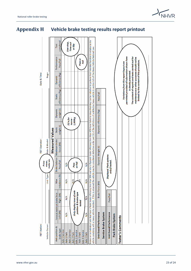
10 Reporting requirements For each test conducted, results must be recorded and maintained for auditing purposes for a period of 5 years or as required by the governing jurisdiction. A copy of the report must be supplied to the driver at the time of the test. This report must include identifying information about the test and the vehicle (i.e. location, date and time of test, make model, unit type e.g. trailer, prime mover, ridged truck etc. and registration and owner of the vehicle). Results of measured values recorded will include: • For each axle position & brake type tested:
o force at maximum brake force (both left and right wheel end in kilonewtons (kN)) o max brake imbalance between wheel ends (%) o brake balance result (Pass/Fail) o maximum brake force (kN) o static weight (t) (where tonne = 1000kg) o dynamic weight (t) o static efficiency (%g) o dynamic efficiency (%g) o performance outcome Pass/Fail o how the test was deemed to be successful – i.e. User stop, Time out or Slip
• For overall unit performance for service brake: o sum of axle brake force (kN) o sum of axle dynamic weight (t) o dynamic efficiency (%g) o overall result (Pass/Fail)
• For overall unit performance for park brake (if tested) o overall result Pass/Fail
• Any additional comments or relevant information Appendix H provides an example of the recommended format of the report printout. It is important to note that as this is an example and variations in the layout may occur between different RBT manufactures. Variations from this report layout are permitted provided all the information shown here is clearly presented.
Note: The content of reports and tests carried out for maintenance or other purposes should not be limited by the content of this procedure.
National roller brake testing
www.nhvr.gov.au 9 of 24
Appendix A Approved alternative and supplementary test procedures
A.1 Supplementary testing methods. The National RBT Procedure defines how in-service brake tests using RBT machines are to be conducted. The procedure has been developed assuming vehicles will be tested at the mass presented, as this is the most practical loading approach for the situations where these tests are conducted.
The NHVR is aware that supplementary test methods are currently available, that include axle restraint and lifting bed, that allow a RBT machine to artificially impose or simulate load, up to regulation mass. These methods are optional and may be used to test brakes through are greater brake force range.
Note: These test methods are supplementary and not substitutes for the National RBT Procedure.
A.2 Vehicles fitted with load sensing valves Where an RBT operator has concerns that the operation of load sensing valves is causing a vehicle or axle to fail the test, the RBT operator may use a load simulator if the RBT machine is so equipped, so that the valve’s operation does not impact the test. The operator must be skilled in the use of the load simulator function to use this option.
Alternatively, the valve linkage may be temporarily disconnected, or otherwise by-passed, immediately before the brake test, to allow the required braking force to be achieved. The RBT operator must ensure that the valve is restored to its proper working condition before the vehicle leaves the testing station. Failure to do so may break the law.
A safety procedure must be followed that specifically details the process that ensures the system is reconnected and enabled and the driver kept informed.
Deceleration test
If the vehicle cannot be roller brake tested, or for any other reason, a decelerometer may be used.
This will be dependent on site restrictions and equipment available.

National roller brake testing
www.nhvr.gov.au 10 of 24
Appendix B RBT machine specifications and settings This procedure depends on the accuracy and consistency of the RBT machines being used. To ensure accuracy and consistency, all RBT machines used to conduct a test in line with this procedure must meet the following requirements:
• Be manufactured to comply with ISO 21069-1, AS/NZS 4613 or another standard recognised by the NHVR • Include vehicle weighing facilities (load cells) • Be capable of automatically calculating the deceleration rate of individual wheels and axles • Be capable of calculating the deceleration rate of a vehicle unit including each vehicle in a vehicle combination • Report and record all brake test results as rates of deceleration, as a percentage of gravity (%g, where gravity is
assumed as 9.81m/s2). This does not preclude the equipment reporting or recording other units of measure in addition to deceleration.
• Report and record peak force imbalance across an axle • Be capable of providing a written report of the results of a brake test. The report must clearly indicate test results as
detailed in Section 10 and Appendix H. • Must be capable of directly storing test results electronically from the RBT machine • Must be capable of calculating results using both dynamic and static mass:
o Must record the static mass and dynamic mass for all tests o Must only use dynamic mass for the purpose of determining and reporting the deceleration
• Use only dynamic test mass for the purposes of any pass or fail indicator for service brake of the overall vehicle unit • Use both static and dynamic test mass for the purposes of any pass or fail indicator for service brake at the axle level • Use only static test mass for the purposes of a pass or fail indicator for park brake • On termination of a test, whether from lock up or manual intervention, both rollers must stop simultaneously • Imbalance must be measured at the same time that the maximum brake force is measured. . The imbalance at
maximum brake force is to be recorded and calculated using the following formula:
% 𝑰𝑰𝑰𝑰𝑰𝑰𝑰𝑰𝑰𝑰𝑰𝑰𝑰𝑰𝑰𝑰𝑰𝑰 = (𝑩𝑩𝑩𝑩𝟏𝟏 − 𝑩𝑩𝑩𝑩𝟐𝟐)
𝑩𝑩𝑩𝑩𝟏𝟏× 𝟏𝟏𝟏𝟏𝟏𝟏%
Where: o BF1 - Maximum brake forces achieved by the higher performing wheel end on an axle o BF2 - Maximum brake forces achieved by the lower performing wheel end on axle
• Terminate the test when the RBT machine detects a speed differential or ‘slip’ between the tyre and the roller of 27% ± 3%1.
• Be independently checked for calibration at intervals not longer than 12 months. The RBT machine calibration and maintenance protocol is detailed in Section 9.
• Manufacturer’s instruction for setup and operation must be provided for all RBT machines and held with the unit. The setup instruction must include a method for confirming operational accuracy of load cells and other components that may affect the accuracy and repeatability of results from the RBT machine.
• The RBT machine must be programmed to deliver results as per the decision trees in Appendix F and Appendix G. • The RBT machine must provide a user interface that allows correct RBT machine operation, in accordance with that
detailed in Appendix I.
1 ISO 21069-1:2004(E) Road vehicles — Test of braking systems on vehicles with a maximum authorised total mass of over 3.5 t using a roller brake tester — Part 1: Pneumatic braking systems, 1.9 c

National roller brake testing
www.nhvr.gov.au 11 of 24
Appendix C Calibration procedure The objective of this section is to minimise RBT machine calibration uncertainty and ensure consistency and confidence in test results accuracy across the range of RBT machines used.
Note: This calibration procedure is to be used in conjunction with the manufacturer’s calibration procedure and maintenance schedule. Where uncertainty exists between this procedure and the manufacturer’s procedure, advice should be sought from the manufacturer on how to comply with this procedure either by calibration and/or maintenance.
The accuracy and repeatability of RBT results depend on many factors, including the:
a) wear and state of repair of the RBT machine b) calibration method c) tools used for calibration and their calibration d) skill level of the maintainers e) skill level of the RBT machine operator f) design and characteristics of the RBT machine g) measurement procedures h) method of calculating result i) vehicle to be tested and how it is prepared.
Items (a) to (d) are addressed in this section.
C.1 The wear and condition of the RBT machine The wear and general condition can have significant impact on the accuracy and repeatability of RBT results.
The manufacture must give maintenance guidance in the form of a manual and/or service bulletins in the following areas:
• Roller wear and damage and the influence they can have on the coefficient of friction, the reduction in roller diameter and how these can affect the force measured by the machine
• Change in internal rotational resistance with wear and degradation of bearings can affect the force measured by the machine
• Important settings such as torque, preloads and lash adjustments that may impact the calibration and /or integrity of the RBT machine.
C.2 Calibration method The RBT machine as a whole must be considered a certified test instrument that is subject to calibration.
For an RBT machine to be used for heavy vehicle in-service brake compliance, the manufacturer must give guidance in the following areas:
• Calibration of all sensors, including deceleration force transducers, load cells and ‘slip’ control • Permissible resistance (e.g. torque) between the point of application of the parameter being measured and sensor • Wear and tear on the rollers that may impact the accuracy of a test, such as roller friction and roller diameter. • Verification that all software or programs functioning correctly and ideally are the latest versions available from the
manufacturer.

National roller brake testing
www.nhvr.gov.au 12 of 24
C.3 Calibration frequency Calibration tolerance and calibration intervals that assure the recorded result (deceleration as calculated from weight and force) is within ±3% of the actual value with a 95% confidence level (The maximum recalibration interval is 12 months with one month leeway to allow for scheduling).
Note: A case can be made for extending this calibration interval to 24 months in locations (e.g. remote areas with small populations) where test volumes are low and the manufacturer verifies that the RBT machine will remain within the calibration limit with a 95% confidence level.
C.4 Tools used for calibration and their calibration The RBT manufacturer must specify the tools to be used for calibration and the accuracy required of the tools. These tools must be maintained and calibrated in line with AS/NZS ISO 9001:2016 Quality management systems – Requirements following the manufacturer’s instructions.
C.5 The skill level of the maintainers The maintainer’s skill level is critical to the accuracy and safety of RBT machines.
It is recognised that maintenance staff with a suitable trade qualification can perform effective maintenance. However, to calibrate RBT machines and perform some critical maintenance, specialist knowledge and training will be required.
RBT machine manufacturers and suppliers must maintain a list of people qualified to calibrate and perform critical maintenance on the RBT machines.
The list must include:
• critical maintenance which requires training • the details of people that can perform critical work to and calibrate RBT machines • details of specific critical maintenance and RBT machines calibration the person can perform To use RBT machines for heavy vehicle in-service brake compliance, all critical maintenance and calibration must be performed by a person approved on the list.
C.6 Calibration and maintenance records Records must be kept for RBT machines used for compliance detailing:
• the maintenance and calibration that has been performed • the details of the person who conducted the calibration and maintenance.

National roller brake testing
www.nhvr.gov.au 13 of 24
Appendix D RBT machines operator qualifications Given the technical nature of a brake test and inspection, a minimum level of technical qualification or experience is required. The NHVR requires that those conducting brake tests and inspections meet the following minimum standards:
• Have sound knowledge of mechanical systems • Have knowledge of heavy vehicle braking systems:
o Can identify different braking systems, for example: o Cardan shaft parking brakes o Single circuit o Dual circuit o ADR 35 and ADR 38 brake systems o Spring brakes o Load sensing valves o ABS and/or EBS systems
o Can identify possible faults and causes o Capable of performing non-invasive visual braking inspections
• Have undertaken training in the operation of RBT machine being used, provided by the manufacturer or supplier and have obtained the competency required
• Understand safety requirements • Have read and understand this procedure.

National roller brake testing
www.nhvr.gov.au 14 of 24
Appendix E Test validation and control This procedure is designed so that the RBT machine will prompt the RBT operator when a test result may be invalid. The information supplements that procedure so that RBT operators can achieve the best test results within the limitations of the test.
This test procedure does not mandate axle restraint or defined loading requirements. Vehicles are tested as presented. This limits the extent to which brake performance can be tested. However, the added information, down to the wheel end level, provided by RBT allows other diagnostic methods of ensuring brake performance that other test methods cannot deliver.
Unique and general aspects of the Australian road transport environment will also influence the test procedure, the results that are achievable and how these result interoperated. Notably, the proportion of the Australian heavy vehicle fleet that use suspensions that are reactive under RBT conditions and long combinations that require time for brake pressures to regenerate and stabilise across the trailers.
These issues are addressed in the relevant section.
E.1 Setup on the rollers Care must be taken when positioning the tyres of the axle under test on the rollers. An axle that is not parallel to the rollers may result in invalid test results for imbalance and may affect when the test is terminated because of slip.
E.2 Applying the brake To achieve good test results from RBT machines, instantaneous static friction must be maintained between the tyre and roller with slowing building brake force to the point where the brake force delivered exceeds static friction limit or the brakes can deliver no more force. To achieve this, brake application must be slow and steadily increasing.
Instruction for the driver
The driver should apply the brakes as if slowing to a rolling stop up to a red light that may change to green. The driver is a distance from the red light so braking starts off light and slowly increases as if the distance to the light is closing.
Testing of lightly laden axles and laden axles that are exhibiting significant load shift will require a lighter touch and the brakes to be applied more slowly.
E.3 Air pressure and supply While the Australian heavy vehicle fleet typically includes longer combinations, with more trailers than other countries, it only occupies a small portion of the global market. This means that vehicles and their components are not always designed with Australia in mind. The impact of this oversight is seen in the capacity of air systems for longer combinations where recharge times are extremely long once the supply is diminished. On long combinations under test conditions, the available air pressure may decrease more quickly as air is consumed across all active brake chambers each time the service brake is applied and spring brakes are released.
The vehicle axle under test should not be below the manufacturer’s air pressure operating range and generally for trailer axles greater than 400kPa (58 psi). Truck manufacturers generally show the air operating pressure range on the truck air gauge. It may take considerable time after the truck has achieved close to the maximum working pressure before the rear most trailer axle group on a long combination has sufficient air pressure to test that axle group.

National roller brake testing
www.nhvr.gov.au 15 of 24
The following recharge times for air systems can be expected depending on the number of trailers:
Table 2: Recharge times for air systems
Number of trailers Recharge times (minutes)
No trailers 1
1 1.5
2 2
3 3
4 4
5 5
If the performance is found to decrease, the further back along a combination the test is performed, these recharge times should be increased. However, excess recharge times may indicate a problem with the air system.
E.4 Factors affecting brake force that can be measured E.4.1 Axle weights (and slip shut off) Normal force (weight) is required on the RBT rollers so that brake performance can be tested. When vehicles are lightly laden, only limited testing of brake capability can be performed. A lighter touch is also required on the brakes to ensure that valid brake results are obtained under these lightly laden conditions.
Lightly laden axles will reach slip shut off under light brake force. Slip shut off indicates the brakes have delivered more brake force than the RBT machines programmed protection permits and friction between the roller and tyres is transitioning from static to dynamic. (Slip shut off protects against the increase wear and damage caused by a skidding tyre.)
Clearly, brakes that achieve slip shut off on an RBT machine cannot be issued a defect notice for low brake performance.
The RBT machines have been programmed to assess brake performance using the dynamic test method so false fails will be highly unlikely; however, the risk of the test overstating result is increased. Slow, steady brake application ensures a better quality test.
E.4.2 Reactive suspensions In the absence of axle restraint, reactive suspensions limit the ability of RBT machines to measure maximum achievable brake force. Through field studies and statistical analysis, the dynamic mass on an axle under test has been shown to vary from 45% to 110%. At a dynamic mass 45-65% of the static mass presented, numerical compliance cannot be shown using the static mass calculation method, as slip shut off will occur. Using the dynamic mass value (weight measured during the test) numerical compliance can be shown. However, the dynamic test method will give a significantly higher result as more load is transferred off an axle.
For RBT operators that have facility for simulated load like axle restraint and axle lift, using these functions provides a more controlled and accurate evaluation of the brakes performance.
Where simulated load is not available, slowing down the brake application rate may improve the test quality and limit the level of load shift. This will become more difficult the more lightly laden the axle under test. This situation can be improved by testing with the vehicle partially laden.
E.4.3 Vehicle smart systems Vehicle smart systems generally will actively limit brake force based on the loading of an axle. Many of these systems will be inactive under the conditions encountered when using RBT machines. Where low brake performance is being encountered and vehicle smart systems may be the cause, refer to section 9 and Appendix A for guidance on the procedure to be used.

National roller brake testing
www.nhvr.gov.au 16 of 24
Appendix F RBT machine decision trees F.1 Service brake test overview - RBT machine decision tree

National roller brake testing
www.nhvr.gov.au 17 of 24
F.2 Service brake test - RBT machine decision tree
Refer to sections G.1 and G.2 for RBT Operator input decision trees 1 and 2.

National roller brake testing
www.nhvr.gov.au 18 of 24
F.3 Service brake test - RBT machine decision tree

National roller brake testing
www.nhvr.gov.au 19 of 24
F.4 Brake balance service brake - RBT machine decision tree

National roller brake testing
www.nhvr.gov.au 20 of 24
F.5 Park brake test - RBT machine decision tree
Emergency and park brakes that act on the wheel ends are assessed at the axle level. If all axles that deliver an emergency and/or park brake functionally pass the above test, the vehicle passes the test.

National roller brake testing
www.nhvr.gov.au 21 of 24
Appendix G RBT operator decision trees G.1 Service brake – User decision tree 1

National roller brake testing
www.nhvr.gov.au 22 of 24
G.2 Service brake – User decision tree 2
National roller brake testing
www.nhvr.gov.au 23 of 24
Appendix H Vehicle brake testing results report printout

National roller brake testing
www.nhvr.gov.au 24 of 24
Appendix I User interface
The RBT machine is required to Interface with user in a way that allows them to:
• test to this procedure and print and save the results;
• choose the brake systems to be tested while testing an axle and the order brake systems are to be tested in but normally in the order below:
o Service brake
o Park brake
• choose to retest any axle for any of the brake systems before the test is accepted
• respond to the special system validation prompts defined below in sections I.1 and I.2
I.1 Service brake high dynamic out of limit Where a high dynamic out of limit as defined in Appendix F.2 is identified prompt the user to retest or accept the test.
This validation event shall prompt the user with the following message:
Dynamic above limit!
Accept or retest?
Retest XXXXXXX (step to be defined by the manufacture)
Accept XXXXXXX (step to be defined by the manufacture)
Retest is to initiate the RBR Machine to perform the normal retest process and the user is to maintain control over the start of retest.
Accept is to initiate the RBT Machine to perform the normal user defined next step in the process and the user is to maintain control over when the next step starts.
I.2 Service brake low brake force measured Where a low brake force measured as defined in Appendix F.2 is identified prompt the user to retest or accept the test.
This validation event shall prompt the user with the following message:
Static below limit!
Accept or retest?
Retest XXXXXXX (step to be defined by the manufacture)
Accept XXXXXXX (step to be defined by the manufacture)
Retest is to initiate the RBT machine to perform the normal retest process and the user is to maintain control over the start of retest.
Accept is to initiate the RBR machine to perform the normal user defined next step in the process and the user is to maintain control over when the next step starts.