Embed Size (px)
Citation preview
For business purposes only. Unauthorized access, use, distribution, or modification of Union Pacific computer systems or theircontent is prohibited by law.
Union Pacific Rules
Air Brake and Train Handling Rules
Effective January 20, 2012Includes Updates as of July 2, 2013PB-20329
Union Pacific Railroad. All Rights Reserved.
These rules become effective at 0001, Friday, January 20, 2012. At that time, all previous rules and instructions that areinconsistent with these rules become void.
30.0: Train Air Brake Tests/Inspections Chapter 3031.0: Locomotive Requirements Chapter 3132.0: Securement/Train Operations - Chapter 3233.0: Distributed Power and Manned Helper Chapter 3334.0: Train Handling Chapter 3435.0: Remote Control Operations Chapter 3536.0: Positive Train Control Chapter 3637.0: Reserved for Future Use - Chapter 3738.0: Commuter/Business Train Operations - Chapter 3839.0: Equipment Charts/Diagrams - Brakes - Chapter 39GLOSSARY: Glossary

Union Pacific Rules Air Brake and Train Handling Rules
30.0: Train Air Brake Tests/Inspections Chapter 30
30.0: Train Air Brake Tests and Inspections30.1: Compliance with FRA Regulations30.1.1: Qualified Inspectors30.2: General Requirements30.2.1: Coupling and Securing Air Hoses30.2.2: Operative Brakes30.2.3: Employee in Charge During Air Brake Test30.2.4: Standard Brake Pipe Pressure30.2.5: Charging Air Brake System30.2.6: Air Brake Tests Using Gauge or End-of-Train Device30.3: Initial Terminal Air Brake Test (Class I Air Brake Test)30.3.1: Initial Terminal Air Brake Test (Class I) Requirements30.3.2: Initial Terminal Air Brake Test (Class I) Procedure30.3.3: Initial Terminal Air Brake Test (Class I) Notification30.3.4: Cycle Trains30.3.5: Trains Designated as Extended Haul30.3.6: Attaching Locomotive to Cars Previously Class I Tested Using Yard Air or Other Locomotive30.4: 1,000 Mile Inspection Tests (Class IA Brake Test)30.4.1: 1,000 Mile Inspection Tests (Class IA Brake Test)30.5: Transfer Train Movement Air Test30.5.1: Transfer Train Movement Air Test30.6: Test When Cutting Off and Recoupling30.6.1: Test When Cutting Off and Recoupling30.7: Application and Release Test (Class III Brake Test)30.7.1: Application and Release Test (Class III Brake Test) Requirements30.8: Inbound Train Inspection30.8.1: Inbound Train Inspection30.9: Train Information30.9.1: Train Information30.10: Air Brake Test and Inspection Charts/49 CFR 23230.10.1: Air Brake Test Requirements30.11: Air Brake Tests and Inspection Procedures30.11.1: Brake Inspection Requirements30.11.2: Brake Pipe Leakage Test

30.0: Train Air Brake Tests and Inspections
30.0 Train Air Brake Tests and Inspections
Rule Updated Date
February 12, 2013
^Top
30.1: Compliance with FRA Regulations
30.1
49 CFR215.13
232.1
Compliance with FRA RegulationsInspect and test brake equipment in accordance with Federal Railroad Administration (FRA)regulations contained within these rules. This is the responsibility of the employee(s) who perform thework, unless otherwise instructed.
The status of the inspection/test must be communicated to the relieving crew verbally or by writtennotification left on the controlling locomotive.
Rule Updated Date
January 20, 2012
^Top
30.1.1: Qualified Inspectors
30.1.1
49 CFR232.203
ReferenceGlossary
Qualified InspectorsInspections and air brake tests must be performed by either a "Qualified Person", "QualifiedMechanical Inspector" or a "Qualified Maintenance Person" as specified by Federal Regulations.
Rule Updated Date
January 20, 2012

^Top
30.2: General Requirements
30.2 General Requirements
Rule Updated Date
January 20, 2012
^Top
30.2.1: Coupling and Securing Air Hoses
30.2.1
49 CFR232.107
Coupling and Securing Air HosesBefore coupling air hoses between locomotives and/or cars, employeesmust:
Rule Updated Date
January 20, 2012
^Top
30.2.2: Operative Brakes
30.2.2
49 CFR232.103
ReferenceSSI Item 2-F
Operative BrakesThese requirements apply to air brake tests and inspections:
Shake debris out of the hoses.
Blow all condensation from the locomotive brake pipe or yard airline.
All cars must have operative air brakes.Exceptions:
Cars with defective air brakes may be moved for repairs when properly tagged on bothsides by a Qualified Mechanical Inspector.Scale test cars are not required to be equipped with air brakes, but if equipped, thebrakes must be operable.Brakes that fail enroute.
Rule Updated Date
July 2, 2013
^Top
30.2.3: Employee in Charge During Air Brake Test
30.2.3
49 CFR232.205
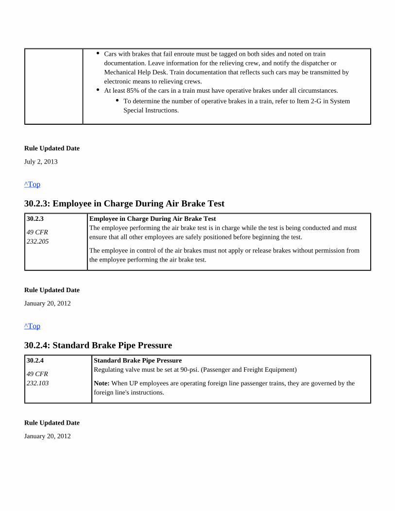
Employee in Charge During Air Brake TestThe employee performing the air brake test is in charge while the test is being conducted and mustensure that all other employees are safely positioned before beginning the test.
The employee in control of the air brakes must not apply or release brakes without permission fromthe employee performing the air brake test.
Rule Updated Date
January 20, 2012
^Top
30.2.4: Standard Brake Pipe Pressure
30.2.4
49 CFR232.103
Standard Brake Pipe PressureRegulating valve must be set at 90-psi. (Passenger and Freight Equipment)
When UP employees are operating foreign line passenger trains, they are governed by theNote:foreign line's instructions.
Rule Updated Date
January 20, 2012
Cars with brakes that fail enroute must be tagged on both sides and noted on traindocumentation. Leave information for the relieving crew, and notify the dispatcher orMechanical Help Desk. Train documentation that reflects such cars may be transmitted byelectronic means to relieving crews.At least 85% of the cars in a train must have operative brakes under all circumstances.
To determine the number of operative brakes in a train, refer to Item 2-G in SystemSpecial Instructions.
^Top
30.2.5: Charging Air Brake System
30.2.5
49 CFR232.103
Reference Rule32.2.132.1.2
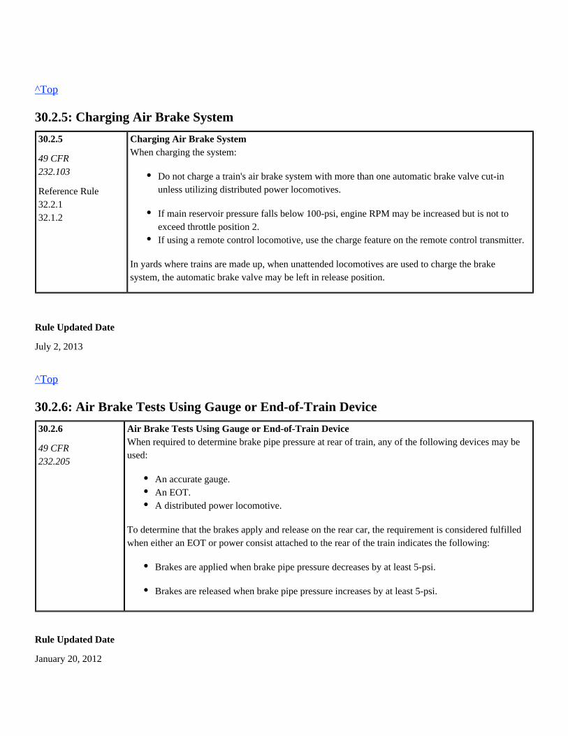
Charging Air Brake SystemWhen charging the system:
In yards where trains are made up, when unattended locomotives are used to charge the brakesystem, the automatic brake valve may be left in release position.
Rule Updated Date
July 2, 2013
^Top
30.2.6: Air Brake Tests Using Gauge or End-of-Train Device
30.2.6
49 CFR232.205
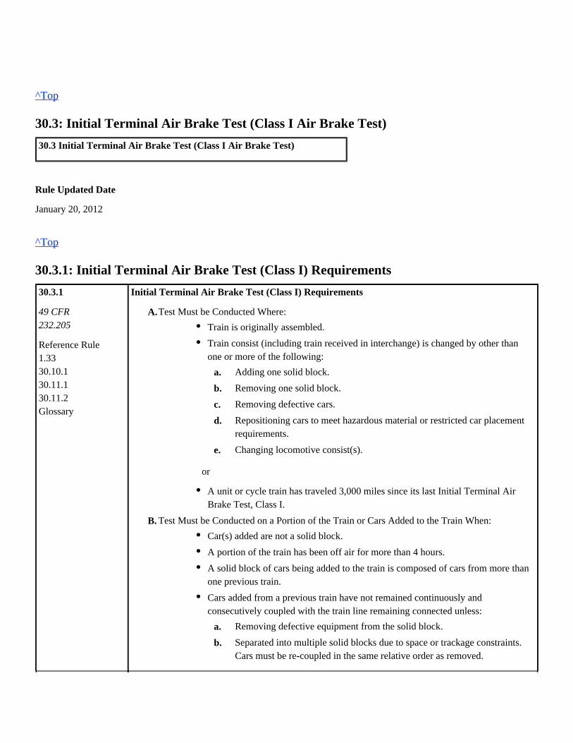
Air Brake Tests Using Gauge or End-of-Train DeviceWhen required to determine brake pipe pressure at rear of train, any of the following devices may beused:
To determine that the brakes apply and release on the rear car, the requirement is considered fulfilledwhen either an EOT or power consist attached to the rear of the train indicates the following:
Rule Updated Date
January 20, 2012
Do not charge a train's air brake system with more than one automatic brake valve cut-inunless utilizing distributed power locomotives.
If main reservoir pressure falls below 100-psi, engine RPM may be increased but is not toexceed throttle position 2.If using a remote control locomotive, use the charge feature on the remote control transmitter.
An accurate gauge.An EOT.A distributed power locomotive.
Brakes are applied when brake pipe pressure decreases by at least 5-psi.
Brakes are released when brake pipe pressure increases by at least 5-psi.
^Top
30.3: Initial Terminal Air Brake Test (Class I Air Brake Test)
30.3 Initial Terminal Air Brake Test (Class I Air Brake Test)
Rule Updated Date
January 20, 2012
^Top
30.3.1: Initial Terminal Air Brake Test (Class I) Requirements
30.3.1
49 CFR232.205
Reference Rule 1.33
30.10.1 30.11.1 30.11.2
Glossary
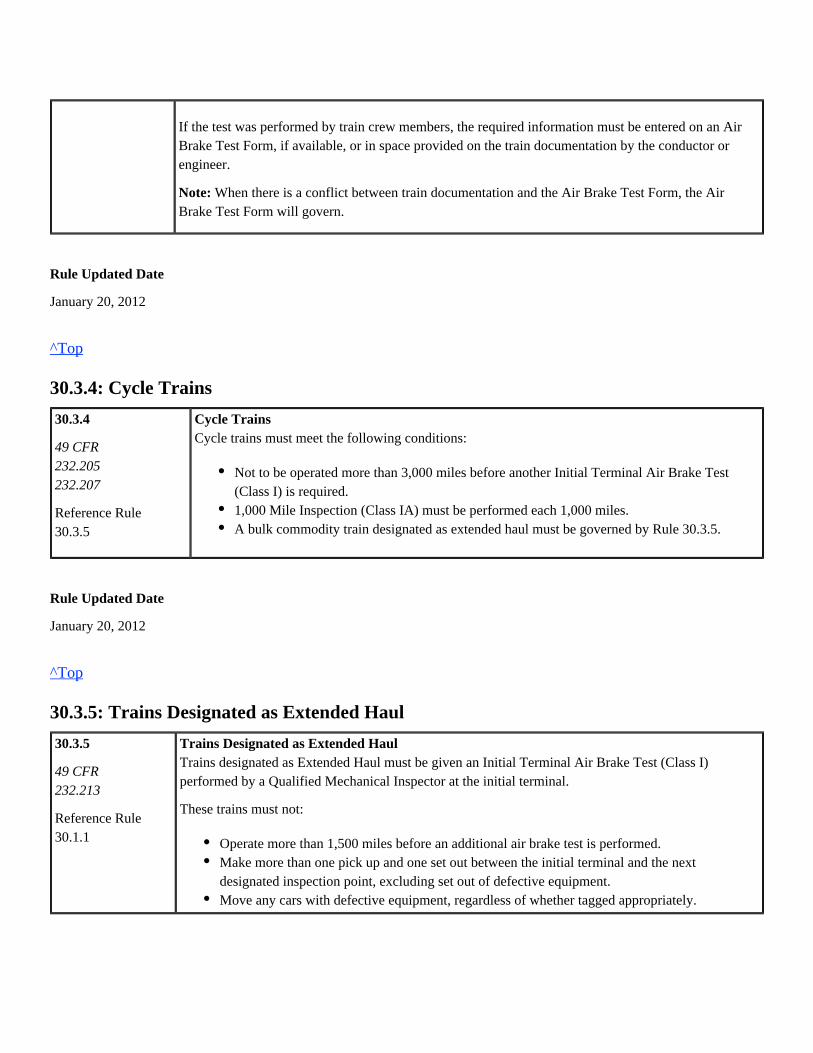
Initial Terminal Air Brake Test (Class I) Requirements
B.
A.Test Must be Conducted Where:
or
Test Must be Conducted on a Portion of the Train or Cars Added to the Train When:
Train is originally assembled.
Train consist (including train received in interchange) is changed by other thanone or more of the following:
e.
d.
c.
b.
a. Adding one solid block.
Removing one solid block.
Removing defective cars.
Repositioning cars to meet hazardous material or restricted car placementrequirements.
Changing locomotive consist(s).
A unit or cycle train has traveled 3,000 miles since its last Initial Terminal AirBrake Test, Class I.
Car(s) added are not a solid block.
A portion of the train has been off air for more than 4 hours.
A solid block of cars being added to the train is composed of cars from more thanone previous train.
Cars added from a previous train have not remained continuously andconsecutively coupled with the train line remaining connected unless:
b.
a. Removing defective equipment from the solid block.
Separated into multiple solid blocks due to space or trackage constraints.Cars must be re-coupled in the same relative order as removed.

Rule Updated Date
January 20, 2012
^Top
30.3.2: Initial Terminal Air Brake Test (Class I) Procedure
30.3.2
49 CFR232.205
Reference Rule30.10.1
Initial Terminal Air Brake Test (Class I) ProcedureWhen performing an Initial Terminal Air Brake Test (Class I), comply with the procedures outlinedin Rule 30.10.1.
Rule Updated Date
January 20, 2012
^Top
30.3.3: Initial Terminal Air Brake Test (Class I) Notification
30.3.3
49 CFR232.205
Reference Rule5.1030.10.1
Initial Terminal Air Brake Test (Class I) NotificationThe engineer and conductor must know they have the required written notification that an InitialTerminal Air Brake Test (Class I) was performed on their entire train. Notification will be left on thecontrolling unit and will include:
Written notification may be provided to the engineer and conductor by:
Name of inspector.Date and time test was completed.Location where test was performed.Number of cars inspected.
Air Brake Test Form at the initial terminal.Electronic means in the space provided on the train documentation.orInformation may be communicated to the engineer or conductor that the test has beencompleted and entered on the Air Brake Test Form or on space provided on traindocumentation.
If the test was performed by train crew members, the required information must be entered on an AirBrake Test Form, if available, or in space provided on the train documentation by the conductor orengineer.
When there is a conflict between train documentation and the Air Brake Test Form, the AirNote:Brake Test Form will govern.
Rule Updated Date
January 20, 2012
^Top
30.3.4: Cycle Trains
30.3.4
49 CFR 232.205
232.207
Reference Rule30.3.5
Cycle TrainsCycle trains must meet the following conditions:
Rule Updated Date
January 20, 2012
^Top
30.3.5: Trains Designated as Extended Haul
30.3.5
49 CFR232.213
Reference Rule30.1.1
Trains Designated as Extended HaulTrains designated as Extended Haul must be given an Initial Terminal Air Brake Test (Class I)performed by a Qualified Mechanical Inspector at the initial terminal.
These trains must not:
Not to be operated more than 3,000 miles before another Initial Terminal Air Brake Test(Class I) is required.1,000 Mile Inspection (Class IA) must be performed each 1,000 miles.A bulk commodity train designated as extended haul must be governed by Rule 30.3.5.
Operate more than 1,500 miles before an additional air brake test is performed.Make more than one pick up and one set out between the initial terminal and the nextdesignated inspection point, excluding set out of defective equipment.Move any cars with defective equipment, regardless of whether tagged appropriately.
Any cars or solid block of cars added enroute must be given an Initial Terminal Air Brake Test (ClassI) by a Qualified Mechanical Inspector (either at the time of pick up or pretested) at the location thecars are added.
Rule Updated Date
January 20, 2012
^Top
30.3.6: Attaching Locomotive to Cars Previously Class I Tested Using Yard Air orOther Locomotive
30.3.6
49 CFR 232.205
232.217
Reference Rule30.332.5.1Glossary
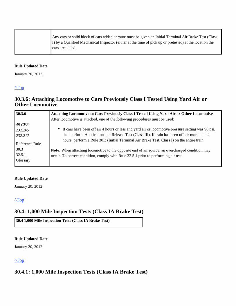
Attaching Locomotive to Cars Previously Class I Tested Using Yard Air or Other LocomotiveAfter locomotive is attached, one of the following procedures must be used:
When attaching locomotive to the opposite end of air source, an overcharged condition mayNote:occur. To correct condition, comply with Rule 32.5.1 prior to performing air test.
Rule Updated Date
January 20, 2012
^Top
30.4: 1,000 Mile Inspection Tests (Class IA Brake Test)
30.4 1,000 Mile Inspection Tests (Class IA Brake Test)
Rule Updated Date
January 20, 2012
^Top
30.4.1: 1,000 Mile Inspection Tests (Class IA Brake Test)
If cars have been off air 4 hours or less and yard air or locomotive pressure setting was 90 psi,then perform Application and Release Test (Class III). If train has been off air more than 4hours, perform a Rule 30.3 (Initial Terminal Air Brake Test, Class I) on the entire train.

30.4.1
49 CFR232.207
Reference Rule30.10.1
1,000 Mile Inspection Tests (Class IA Brake Test)At designated locations, comply with procedures outlined by Rule 30.10.1.
Rule Updated Date
January 20, 2012
^Top
30.5: Transfer Train Movement Air Test
30.5 Transfer Train Movement Air Test
Rule Updated Date
January 20, 2012
^Top
30.5.1: Transfer Train Movement Air Test
30.5.1
49 CFR232.215
Reference Rule30.10.1
Transfer Train Movement Air TestA train making transfer movements not exceeding 20 miles in one direction is considered a transfertrain. Intermediate switching is permitted enroute. Comply with the procedures outlined in Rule30.10.1.
Rule Updated Date
January 20, 2012
^Top
30.6: Test When Cutting Off and Recoupling
30.6 Test When Cutting Off and Recoupling
Rule Updated Date
January 20, 2012
^Top
30.6.1: Test When Cutting Off and Recoupling
30.6.1
49 CFR232.211
Reference Rule 30.3.1
30.5.1
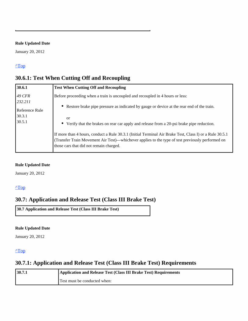
Test When Cutting Off and Recoupling
Before proceeding when a train is uncoupled and recoupled in 4 hours or less:
If more than 4 hours, conduct a Rule 30.3.1 (Initial Terminal Air Brake Test, Class I) or a Rule 30.5.1(Transfer Train Movement Air Test)—whichever applies to the type of test previously performed onthose cars that did not remain charged.
Rule Updated Date
January 20, 2012
^Top
30.7: Application and Release Test (Class III Brake Test)
30.7 Application and Release Test (Class III Brake Test)
Rule Updated Date
January 20, 2012
^Top
30.7.1: Application and Release Test (Class III Brake Test) Requirements
30.7.1 Application and Release Test (Class III Brake Test) Requirements
Test must be conducted when:
Restore brake pipe pressure as indicated by gauge or device at the rear end of the train.
orVerify that the brakes on rear car apply and release from a 20-psi brake pipe reduction.

49 CFR232.211
Reference Rule30.330.3.630.10.133.6
Comply with the procedures outlined in Rule 30.10.1
Rule Updated Date
January 20, 2012
^Top
30.8: Inbound Train Inspection
30.8 Inbound Train Inspection
Rule Updated Date
January 20, 2012
^Top
30.8.1: Inbound Train Inspection
30.8.1
Reference Rule32.1.3
Inbound Train Inspection
Make a 70-psi brake pipe reduction at terminals where the Mechanical Department will makeimmediate air brake inspections and repairs after locomotives are detached.
Rule Updated Date
January 20, 2012
Any change is made to a locomotive consist.A caboose is changed.Picking up a block of previously tested cars that have not been off air for more than 4 hours.Helper locomotives are added anywhere in the train or removed from other than the rear endof the train.One or more consecutive cars are set out of the train.Defective equipment is set out of train.
orRearranging previously tested cars in train for hazardous materials, train make-up, or helperplacement.

^Top
30.9: Train Information
30.9 Train Information
Rule Updated Date
January 20, 2012
^Top
30.9.1: Train Information
30.9.1
49 CFR232.211
Train Information
A train crew taking charge of its train will be provided a train consist. If a consist is not available or ifthe consist does not include all the following, the information may be provided by other means:
Rule Updated Date
January 20, 2012
^Top
30.10: Air Brake Test and Inspection Charts/49 CFR 232
Rule Updated Date
January 20, 2012
^Top
30.10.1: Air Brake Test Requirements
Freight Air Brake Tests
1.
2.
3.
4.
Weight and length of the train.
Weight distribution of train, if necessary, for proper train handling.
Information related to car or locomotive defects.
If train air brake test, i.e., Class I or Class IA, is required prior to next crew change point.

Type of
Test
Perform
safety
inspection
per
Rule 1.33
Charge
system to
at least
75-psi at
rear of
train as
indicated
by gauge
or
device.
Leakage
test as
required
per rule
30.11.2
20-psi
brake
pipe
reduction
Brake application
and inspection per
rule 30.11.1
Release brakes and
check release1
Brake
pipe
pressure
being
restored
as
indicated
by gauge
or device
at rear of
train
Brake test
notification
required
All
cars
Car(s)
picked
up
Rear
car5
All
cars
Cars(s)
picked
up
Rear
car5
30.3
Class I
X X X X X X X X
30.3.5
Ext. Haul2X X X X X X X X
30.3.1/30.3.52
Car added
enroute
X X X X X X X X X
30.4.1
Class IA
X X X X X
30.5.1
Transfer
Train3
X X X X X3
30.6.1
Recoupling
X
30.7.1
Class III
X X4 X X X X
Rolling release inspection may be made not exceeding 10 MPH.1
Cars must be inspected by a Qualified Mechanical Inspector.2
Cars added enroute must be tested as required by Rule 30.5.1. When cars are set out—determine that brake pipe pressure at3
the rear car has been restored.
Required when cars were previously tested from a Yard Test Plant.4
Class III rear car brake requirements are considered fulfilled when brake pipe pressure is decreased by 5 psi and increased by5
5 psi per Rule 30.2.6.
Rule Updated Date
January 20, 2012

^Top
30.11: Air Brake Tests and Inspection Procedures
30.11 Air Brake Tests and Inspection Procedures
Rule Updated Date
January 20, 2012
^Top
30.11.1: Brake Inspection Requirements
30.11.1
49 CFR232.205
Brake Inspection RequirementsInspect both sides of the cars while performing the air brake test to determine that:
Angle cocks are properly positioned.Air hoses are in condition for service and properly coupled.Air brake system leakage is minimal; if necessary, make repairs to reduce leakage.Retaining valves are in exhaust (EX) position.Piston travel meets the following requirements:
Brakes are applied and remain applied until signal is given to release the brakes. If any car'sbrakes release prior to signal being given to release the brakes, then that car may be retestedonce. On retest, the brakes must remain applied for at least 3 minutes.Brake rigging does not bind or foul.All parts of the brake equipment are properly secured.
Comply with requirements as outlined by stenciling or badge plate.Truck-mounted brake piston travel must be within the limits of the travel indicator whenbrakes are set and provide brake shoe clearance when brakes are released.orBody-mounted brake requirements:
Class I air brake test must be between 6 and 9 inches when brakes are set.Class IA and Transfer Train Test, piston travel must be between 6 and 10 1/2inches. When piston travel exceeds 10 1/2 inches it is no longer considered anoperative brake.

Rule Updated Date
January 20, 2012
^Top
30.11.2: Brake Pipe Leakage Test
30.11.2
49 CFR232.205
ReferenceRule 30.10.1
Brake Pipe Leakage TestWhen a leakage test is required per Rule 30.10.1, use one of the following methods:
A. Air Flow Method (AFM)
To qualify a non-DP train's air brake system, use AFM as follows:
B. Brake Pipe Leakage Method
If unable to use AFM, conduct a brake pipe leakage test as follows:
C. Distributed Power Trains
The Distributed Power system's automated brake pipe leakage function must be used when checkingleakage on DP trains.
Rule Updated Date
The controlling locomotive must be equipped with an AFM indicator with a direct reading ofair flow in increments no greater than 10 cubic feet per minute (CFM).After charging the brake system to at least 75-psi., air flow must not exceed 60 CFM. If airflow exceeds 60 CFM, then the train must be inspected for leakage. Once the leakage iscorrected, the train must be re-tested.
1.
2.
3.
4.
5.
6.
Charge the brake system to at least 75-psi.
After the signal is received, reduce brake pipe pressure by 20-psi.
After the brake pipe exhaust stops, wait 1 minute.
Cut-out the automatic brake valve, and then wait an additional minute for brake pipe pressure toequalize.
Time the brake pipe leakage for 1 minute. If the leakage does not exceed 5-psi, then the test iscomplete. If the leakage exceeds 5-psi, then the train must be inspected; the leakage must becorrected, and the train must be re-tested.
After receiving the proper signal, release the brakes.

January 20, 2012
^Top

Union Pacific Rules Air Brake and Train Handling Rules
31.0: Locomotive Requirements Chapter 31
31.0: Locomotive Consist Requirements31.1: Taking Charge of Locomotive Consist31.2: Locomotive Inspections31.2.1: Inspection Requirements31.2.2: Complete Required Daily Inspection Forms31.2.3: Event Recorder/Track Image Recorder31.2.4: Speed Indicator31.2.5: Locomotive with Non-complying Condition Safe to Move31.2.6: Defects Other than Non-complying Conditions31.2.7: Major Internal Defects31.3: Locomotive Air Brake Tests31.3.1: Locomotive Consist Air Brake Test Requirements31.4: Standard Air Pressure31.4.1: Standard Locomotive Air Pressures31.5: Dynamic Brake/Locomotive Warnings31.5.1: Dynamic Brakes31.5.2: Dynamic Brake Warning Light31.5.3: Wheel Slip Warning Light31.6: Moving Locomotives31.6.1: Moving Light Locomotive Consists31.6.2: Locomotive Consist Limits31.6.3: Hostling Locomotive31.6.4: Moving Locomotives within Mechanical Department Limits31.6.5: Turntable31.7: Locomotive Placement31.7.1: Locomotive Alignment Control31.8: Locomotive Inspections and Procedures31.8.1: Conducting a Locomotive Daily Inspection31.8.2: Changing Operating Ends Procedure31.8.3: Light Engine Setup31.8.4: Procedure for Conducting Locomotive Consist Air Brake Test31.8.4.1: Light Engine Running Air Brake Test.31.8.4.2: Remote Control Light Engine Running Air Brake Test31.8.4.3: Electronic Alertness Control Device (Alerter) Test

31.0: Locomotive Consist Requirements
31.0 Locomotive Consist Requirements
Rule Updated Date
January 20, 2012
^Top
31.1: Taking Charge of Locomotive Consist
31.1
49 CFR 218.55 218.57
229.23
Reference Rule31.831.8.4.3
Taking Charge of Locomotive Consist
Engineers are responsible for the following:
Locomotive Safety Devices
Inspect that required safety devices and systems are cut-in and sealed on lead controlling locomotive forthe route to be used except:
When the controlling locomotive on the lead consist is equipped with an Electronic Alertness ControlDevice (alerter), the device must be tested per Rule 31.8.4.3 prior to departure from a train's initialterminal, or when the controlling locomotive is changed enroute, to ensure that a penalty brakeapplication of the locomotive brakes will occur if the warning timing cycle expires. If a penalty brakeapplication does not occur, the locomotive must not be used as a controlling locomotive.
31.8.5: Starting Procedure31.8.6: Weak Batteries31.8.7: Locomotive Fuel Conservation and TPA Compliance31.8.7.1: Shutdown Procedure31.8.7.2: Prevent Engine Cooling System from Freezing
Checking that the locomotive daily inspection card is current on the controlling locomotive.Verify that "Blue Card" is displayed under a transparent cover in the cab of each locomotive.Union Pacific locomotives have an entry at the bottom of the blue card which reads "Do Not UseAfter mm/dd/yy". Verify that the locomotive has not passed this date.Verifying that the brake system is in proper condition for use.
When a safety device becomes defective enroute.
orDuring drag loading/unloading operations under 5 MPH.
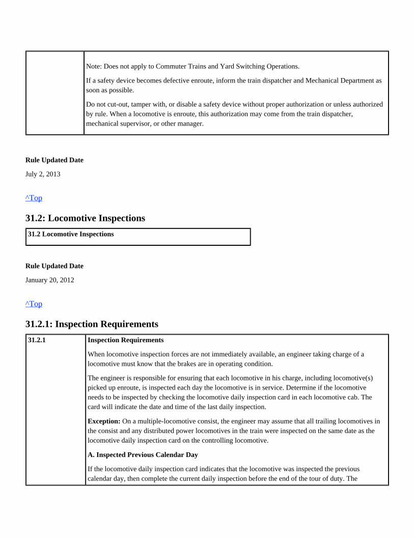
Note: Does not apply to Commuter Trains and Yard Switching Operations.
If a safety device becomes defective enroute, inform the train dispatcher and Mechanical Department assoon as possible.
Do not cut-out, tamper with, or disable a safety device without proper authorization or unless authorizedby rule. When a locomotive is enroute, this authorization may come from the train dispatcher,mechanical supervisor, or other manager.
Rule Updated Date
July 2, 2013
^Top
31.2: Locomotive Inspections
31.2 Locomotive Inspections
Rule Updated Date
January 20, 2012
^Top
31.2.1: Inspection Requirements
31.2.1 Inspection Requirements
When locomotive inspection forces are not immediately available, an engineer taking charge of alocomotive must know that the brakes are in operating condition.
The engineer is responsible for ensuring that each locomotive in his charge, including locomotive(s)picked up enroute, is inspected each day the locomotive is in service. Determine if the locomotiveneeds to be inspected by checking the locomotive daily inspection card in each locomotive cab. Thecard will indicate the date and time of the last daily inspection.
On a multiple-locomotive consist, the engineer may assume that all trailing locomotives inException:the consist and any distributed power locomotives in the train were inspected on the same date as thelocomotive daily inspection card on the controlling locomotive.
A. Inspected Previous Calendar Day
If the locomotive daily inspection card indicates that the locomotive was inspected the previouscalendar day, then complete the current daily inspection before the end of the tour of duty. The

engineer may be relieved from requirements to perform a daily inspection when instructions providefor mechanical forces to make the inspection.
Ensure that the Electronic Locomotive Inspection Report is completed.
Inspection should be performed during daylight hours when possible.
B. Not Inspected Previous Calendar Day
If the locomotive daily inspection card indicates that the locomotive was not inspected during theprevious day, or if there is no record on the locomotive, inspect the locomotive before it is placed intoservice on the current day.
C. Locomotive Picked Up Enroute
When picking up a locomotive on line, the engineer must determine which locomotives will require adaily inspection. No locomotive in resulting consist may have a date older than the lead controllinglocomotive.
D. Locomotive Set Out on Line
When setting out a locomotive on line that was inspected on the previous calendar day, inspect thelocomotive, unless notified that the locomotive will be inspected by the Mechanical Department.
Rule Updated Date
January 20, 2012
^Top
31.2.2: Complete Required Daily Inspection Forms
31.2.2
49 CFR229.21
Complete Required Daily Inspection Forms
Locomotive Inspection ReportComplete an Electronic Locomotive Inspection Report for each locomotive inspected.
The locomotive daily inspection card must include the following information:
The locomotive daily inspection card must remain in the holder in the locomotive cab.
Date.Location.Time.Complying or non-complying (check appropriate box).Union Pacific employee number. Legible signatures may be used by other than UnionPacific employees.

Rule Updated Date
January 20, 2012
^Top
31.2.3: Event Recorder/Track Image Recorder
31.2.3 Event Recorder/Track Image Recorder
Only authorized personnel may remove the recorder data pack or download recorderdata.
Rule Updated Date
January 20, 2012
^Top
31.2.4: Speed Indicator
31.2.4
49 CFR229.117
Speed Indicator
A. Speed Indicator Test
The engineer must test the speed indicator of the controlling locomotive using identified test miles ormile posts as soon as possible after departure.
B. Operative Speed Indicator
A locomotive used as a controlling unit at speeds above 20 MPH must be equipped with an operativespeed indicator.Speed indicator requirements:
A speed indicator that exceeds the above tolerances must be handled as aNote:non-complying condition found enroute.
C. Speed Indicator Fails Enroute
If a speed indicator on a controlling locomotive fails enroute, the locomotive may continue as acontrolling locomotive at normal track speed only to the next facility where repairs can be made or untilthe locomotive is due a daily inspection, whichever occurs first. Movement beyond a facility whererepairs can be made or location where daily inspection was conducted must not exceed 20 MPH.
Locomotive speed indicators must be accurate within:
±3 MPH at speeds between 10 and 30 MPH.±5 MPH at speeds above 30 MPH.

Rule Updated Date
January 20, 2012
^Top
31.2.5: Locomotive with Non-complying Condition Safe to Move
31.2.5
Reference Rule31.8
Locomotive with Non-complying Condition Safe to Move
A. During the locomotive daily inspection, if a non-complying condition is discovered, it may bemoved only:
Exceptions:
Prior to moving a non-complying locomotive, perform the following:
As a single locomotive under power not attached to cars.In a locomotive consist not attached to cars.If isolated or shut down when attached to cars.
A controlling locomotive found with defective speed indicator during daily inspection may beoperated under power attached to cars not exceeding 20 MPH.Locomotives found with any of the following defects during the daily inspection may beoperated under power attached to cars as a trailing locomotive:
Inoperative headlights.Both ditch lights inoperative.Inoperative horn or bell.Defective speed indicator.Window cracks that obscure view.Cab seats not properly secured.Inoperative automatic or independent brake controls.Inoperative electronic alertness control device on lead locomotive.
1. Complete a non-complying locomotive tag, and attach it to the isolation switch of thenon-complying locomotive. The tag must include the following information:
"Non-complying locomotive" written on the tag.
Locomotive initials and number.
Name of the inspecting railroad.
Inspection location and date.
Nature of the defect.
Movement restrictions, if any.
Destination.
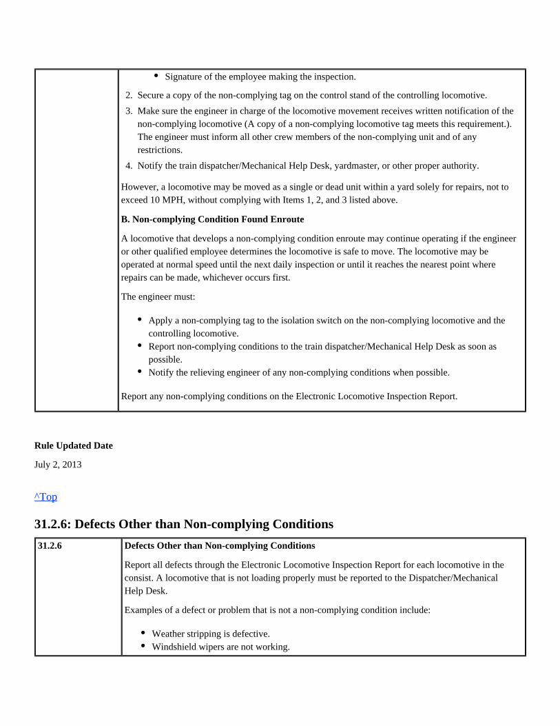
However, a locomotive may be moved as a single or dead unit within a yard solely for repairs, not toexceed 10 MPH, without complying with Items 1, 2, and 3 listed above.
B. Non-complying Condition Found Enroute
A locomotive that develops a non-complying condition enroute may continue operating if the engineeror other qualified employee determines the locomotive is safe to move. The locomotive may beoperated at normal speed until the next daily inspection or until it reaches the nearest point whererepairs can be made, whichever occurs first.
The engineer must:
Report any non-complying conditions on the Electronic Locomotive Inspection Report.
Rule Updated Date
July 2, 2013
^Top
31.2.6: Defects Other than Non-complying Conditions
31.2.6 Defects Other than Non-complying Conditions
Report all defects through the Electronic Locomotive Inspection Report for each locomotive in theconsist. A locomotive that is not loading properly must be reported to the Dispatcher/MechanicalHelp Desk.
Examples of a defect or problem that is not a non-complying condition include:
1.
2.
3.
4.
Secure a copy of the non-complying tag on the control stand of the controlling locomotive.
Make sure the engineer in charge of the locomotive movement receives written notification of thenon-complying locomotive (A copy of a non-complying locomotive tag meets this requirement.).The engineer must inform all other crew members of the non-complying unit and of anyrestrictions.
Notify the train dispatcher/Mechanical Help Desk, yardmaster, or other proper authority.
Signature of the employee making the inspection.
Apply a non-complying tag to the isolation switch on the non-complying locomotive and thecontrolling locomotive.Report non-complying conditions to the train dispatcher/Mechanical Help Desk as soon aspossible.Notify the relieving engineer of any non-complying conditions when possible.
Weather stripping is defective.Windshield wipers are not working.

Rule Updated Date
January 20, 2012
^Top
31.2.7: Major Internal Defects
31.2.7 Major Internal Defects
If a locomotive has a major internal defect, shut down the engine and do not restart until inspectedby mechanical forces.
Report condition to Dispatcher/Mechanical Help Desk, and fill out a "Non-Complying Locomotive"tag. Attach the tag near the engine starting control.
If instructed to set out locomotive, leave the locomotive where mechanical personnel can access it,when possible.
Rule Updated Date
January 20, 2012
^Top
31.3: Locomotive Air Brake Tests
31.3 Locomotive Air Brake Tests
Rule Updated Date
January 20, 2012
^Top
31.3.1: Locomotive Consist Air Brake Test Requirements
31.3.1 Locomotive Consist Air Brake Test Requirements
One headlight bulb is burned out.Ground relay is tripped.Safety valve on the air compressor or main reservoir is popping off.

Reference Rule31.8.231.8.431.8.4.1
Conduct a locomotive air brake test when:
Rule Updated Date
January 20, 2012
^Top
31.4: Standard Air Pressure
31.4 Standard Air Pressure
Rule Updated Date
January 20, 2012
^Top
31.4.1: Standard Locomotive Air Pressures
31.4.1 Standard Locomotive Air Pressures
Before initiating movement, ensure that air pressures are as follows:
Foreign line locomotives may require different main reservoir and brake cylinderNote:pressures.
Rule Updated Date
January 20, 2012
Making up a locomotive consist.Adding locomotive to a consist.Other than rear locomotive is removed from consist.Locomotive consist is rearranged.
orChanging operating ends.
Main reservoir pressure is 120 to 140-psi.Locomotive brake cylinder pressure must be adjusted to pressure indicated on badgeplate.

^Top
31.5: Dynamic Brake/Locomotive Warnings
31.5 Dynamic Brake/Locomotive Warnings
Rule Updated Date
January 20, 2012
^Top
31.5.1: Dynamic Brakes
31.5.1 49 CFR 232.109 Reference
Rule31.8.1
Dynamic Brakes
A. Controlling Dynamic BrakeOn train movements equipped with operative dynamic brakes, the lead controlling locomotive musthave:
The above requirement would not apply to low-speed yard and transfer movements on level orNote:near level grade.
– B. Controlling Dynamic Brake Enroute FailureMay continue operating as the lead locomotive if:
C. Locomotives with Inoperative Dynamic Brakes Inoperative dynamic brake:
Tag indicating inoperative dynamic brakes should include the following information:
An operative dynamic brake.orThe ability to control the operative dynamic brakes of trailing locomotives in a consist and anoperative accelerometer that displays current change in speed or predicted change in speed inmiles per hour per minute.
The engineer or other qualified employee determines the train is safe to move.The train may then be operated at normal speed until:
The train reaches the nearest repair point.orThe lead locomotive can be replaced.
Must be individually tagged, and an additional defect tag must be left on the controllinglocomotive as information to the locomotive engineer.Information may be shown on train consist.

Dynamic brakes cut-out to comply with dynamic brake axle limitations are not consideredinoperative brakes.
Rule Updated Date
January 20, 2012
^Top
31.5.2: Dynamic Brake Warning Light
31.5.2
49 CFR229.115
Dynamic Brake Warning Light
If the Dynamic Brake Warning Light illuminates, reduce the dynamic brake until the light goes out.If condition continues, cut-out the dynamic brake on defective unit.
Rule Updated Date
January 20, 2012
^Top
31.5.3: Wheel Slip Warning Light
31.5.3
49 CFR229.115
Wheel Slip Warning Light
If the wheel slip light is illuminated, reduce power or dynamic brake until the light goes out. If lightdoes not go out:
A wheel slip light continuously illuminated for 6–8 seconds or longer at speeds aboveWARNING:15 MPH may indicate a locked wheel or a slipped pinion gear. Should this occur, stop and determinethat all wheels rotate freely.
Locomotive number.Name of discovering railroad.Location and date condition discovered.Signature of person discovering the condition.
Ensure that wheels are rotating freely.If wheels rotate freely and wheel slip light remains on during throttle reduction, isolate affectedlocomotive.If the wheels do not rotate freely, notify the dispatcher and set out the locomotive.

Rule Updated Date
January 20, 2012
^Top
31.6: Moving Locomotives
31.6 Moving Locomotives
Rule Updated Date
January 20, 2012
^Top
31.6.1: Moving Light Locomotive Consists
31.6.1 Moving Light Locomotive Consists
Operate a light locomotive consist from the cab nearest the direction of travel when any one of thefollowing conditions exists:
This may not be required when it is necessary to maintain a DP link when moving aExceptions:locomotive to train or when other operating conditions prevent occupying the cab nearest thedirection of travel.
Rule Updated Date
January 20, 2012
^Top
31.6.2: Locomotive Consist Limits
31.6.2
Reference Rule31.8.3
Locomotive Consist Limits
Limit freight trains to eight locomotives on the lead consist. The maximum of eight locomotivesincludes units that are:
Distance to be traveled exceeds 2 miles.A member of the same crew does not control movement using hand signals or radio.orVisibility is impaired.

Train management may authorize up to 10 locomotives in the lead consist on freight trains but mustnot exceed power axle and dynamic brake limitations.
The eight locomotive limit does not apply to power transfers. Limit power transfers to a maximum of25 locomotives.
Do not move or switch more than eight coupled locomotives within locomotive servicing facilities.This includes movements between service tracks and train yards.
Rule Updated Date
January 20, 2012
^Top
31.6.3: Hostling Locomotive
31.6.3 Hostling Locomotive
Multiple locomotive consists may be moved within a terminal area with only the brake pipeconnected, provided the speed does not exceed 10 MPH.
Perform the following inspection and test before the initial movement of locomotives coupledtogether and whenever locomotives are added or the controlling locomotive is changed:
Working.Isolated.Dead-in-consist.
orDead-in-train immediately behind the locomotive consist.
1.
2.
3.
4.
5.
6.
Brake pipe is connected and angle cocks are open between each locomotive.
Automatic brake valve must be cut-out on all locomotives coupled together except thecontrolling locomotive.
Independent brake valve must be cut-in on the lead unit on each consist and handle in release.
Allow brake pipe to charge.
Perform a standing brake test as follows:
d.
c.
b.
a. Make a 10-psi service brake application.
Ensure that sufficient locomotive brakes apply for safe movement. Brakes may not apply on locomotives that are shut down unless the dead engineNote:
feature is cut-in.
Release the automatic brake application.
Ensure brakes release on each locomotive.

Rule Updated Date
January 20, 2012
^Top
31.6.4: Moving Locomotives within Mechanical Department Limits
31.6.4 Moving Locomotives within Mechanical Department Limits
When moving locomotives within Mechanical Department limits:
Rule Updated Date
January 20, 2012
^Top
31.6.5: Turntable
31.6.5 Turntable
Do not move on or off a turntable unless correctly lined andlocked.
Rule Updated Date
January 20, 2012
^Top
31.7: Locomotive Placement
31.7 Locomotive Placement
5.
6. Release all hand brakes.
1.
2.
Charge and properly position brake equipment before moving the controlling locomotive.
On controlling locomotive, apply and release locomotive brakes to verify that brake cylinderpistons are operating and brake cylinder lines to trucks are not cut-out.

Rule Updated Date
January 20, 2012
^Top
31.7.1: Locomotive Alignment Control
31.7.1 Locomotive Alignment Control
LOCOMOTIVEPLACEMENT
TABLE
Locomotives Equippedfor MU
Locomotives Not Equipped for MU.
UP and ForeignLine/Waybilled
Locomotives withAlignment
Control
When running, they may be placedanywhere in consist. If shutdown or
isolated, place behind lead consist andMU.
Couple directly behind lead consist and set-up byMechanical Department.
UP Locomotivewithout
AlignmentControl
When consist has locomotives withalignment control, they must be placedsecond in consist, one per train when
handling cars.
Shut down and place between the tenth and fifth carsfrom rear of train. If two locomotives are handled in
one train, they must be separated by one car. No morethan two may be cut-in to a train.
Entrained locomotives must be set-up by MechanicalDepartment.When consist has no locomotives with
alignment control, up to threenon-alignment control locomotives may
be placed on head end when handling cars.
On light locomotive consist, up to fivelocomotives may be handled on rear of
consist.
ForeignLine/Waybilled
Locomotiveswithout
AlignmentControl
Special Train Move only (light locomotive consist)

Rule Updated Date
January 20, 2012
^Top
31.8: Locomotive Inspections and Procedures
31.8 Locomotive Inspections and Procedures
Rule Updated Date
January 20, 2012
^Top
31.8.1: Conducting a Locomotive Daily Inspection
31.8.1
49 CFR229.21 229.53 232.105 236.553
Conducting a Locomotive Daily InspectionInspect these three general areas of each locomotive:
B-units and units designated or modified not to be occupied are not required to have or beNote:equipped with all the devices included in the inspection.
Remote control locomotives (RCL) must be in manual mode when conducting inspection.
Not all defects are non-complying conditions. The following items are non-complying conditions ifthey do not function properly during the daily inspection.
A. Control Compartment/Locomotive CabOperate sanders to deposit sand in front of each locomotive's lead wheels using the reverser position todetermine the direction.
On each locomotive ensure that:
Control Compartment/Locomotive Cab.Walkways and Engine Compartments.Ground Level.
Each air gauge registers within 3-psi of the required pressure.Locomotive cab is free of stumbling or slipping hazards.No traction motors have been cut-out. However, on GE AC, GE-8 DC, GE-9 DC, and EMDAC locomotives, one or more traction motors/trucks may be cut-out and not considered anon-complying condition.Cab seats are properly secured.
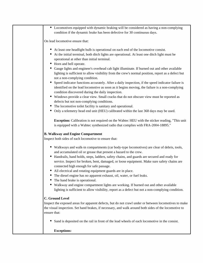
On lead locomotive ensure that:
B. Walkway and Engine CompartmentInspect both sides of each locomotive to ensure that:
C. Ground LevelInspect the exposed areas for apparent defects, but do not crawl under or between locomotives to makethe visual inspection. Set hand brakes, if necessary, and walk around both sides of the locomotive toensure that:
Locomotives equipped with dynamic braking will be considered as having a non-complyingcondition if the dynamic brake has been defective for 30 continuous days.
At least one headlight bulb is operational on each end of the locomotive consist.At the initial terminal, both ditch lights are operational. At least one ditch light must beoperational at other than initial terminal.Horn and bell operate.Gauge lights and engineer's overhead cab light illuminate. If burned out and other availablelighting is sufficient to allow visibility from the crew's normal position, report as a defect butnot a non-complying condition.Speed indicator functions accurately. After a daily inspection, if the speed indicator failure isidentified on the lead locomotive as soon as it begins moving, the failure is a non-complyingcondition discovered during the daily inspection.Windows provide a clear view. Small cracks that do not obscure view must be reported asdefects but not non-complying conditions.The locomotive toilet facility is sanitary and operational.Only a telemetry head end unit (HEU) calibrated within the last 368 days may be used.
Calibration is not required on the Wabtec HEU with the sticker reading, "This unitException:is equipped with a Wabtec synthesized radio that complies with FRA-2004-18895."
Walkways and walk-in compartments (car body-type locomotives) are clear of debris, tools,and accumulated oil or grease that present a hazard to the crew.Handrails, hand holds, steps, ladders, safety chains, and guards are secured and ready forservice. Inspect for broken, bent, damaged, or loose equipment. Make sure safety chains areconnected high enough for safe passage.All electrical and rotating equipment guards are in place.The diesel engine has no apparent exhaust, oil, water, or fuel leaks.The hand brake is operational.Walkway and engine compartment lights are working. If burned out and other availablelighting is sufficient to allow visibility, report as a defect but not a non-complying condition.
Sand is deposited on the rail in front of the lead wheels of each locomotive in the consist.
Exceptions:

Rule Updated Date
January 20, 2012
^Top
31.8.2: Changing Operating Ends Procedure
31.8.2 Changing Operating Ends Procedure
Fuel tank is not leaking.No defects such as cracks and broken or missing parts are on the following:
Brake cylinder piston travel shall be sufficient to provide brake shoe clearance when the brakesare released.Maximum brake cylinder piston travel is 1 1/2 inches less than the travel entered on FRA FormF 6180-49A (blue card) in the locomotive cab.Brake shoes are secured and approximately in line with the tread of the wheel with no obviouslips or overhangs.Foundation brake rigging is secured, and all components other than wheels and sand hoses areat least 2 1/2 inches above the top of the rail.Snowplow, pilot, or endplate is properly secured and is between 3 inches and 6 inches abovethe top of the rail.No part of the electrical cable is lying on the coupler.Unused electrical cables are stowed, or the disconnected ends are placed into a dummyreceptacle or a multiple-unit cable holder.There is no apparent physical damage to the ATC/ACS receiver bars on locomotives equippedwith ATC/ACS.
In road service as lead locomotive, if sanders are found to be defective enroute, thelocomotive may continue in service until it is placed in a repair facility but under noconditions for more than 14 calendar days.In road service as a trailing locomotive, if sanders are found to be defective enroute, thelocomotive may continue in service until it is placed in a repair facility.In switching service, if sanders are found to be defective at a location where repairfacilities are not available, the locomotive may remain in service for no more than 7calendar days.
Locomotive trucks.Wheels.Gear cases.Draft gears.
These bars are located above the rail and in front of the wheels. This requirementapplies only to lead locomotives on trains operating in ATC/ACS territory. Anyapparent damage must be reported, but it does not constitute a non-complying defect.

Reference Rule31.8.4.1
Change operating ends on a locomotive consist by cutting out the operating controls on the controllingend and proceeding immediately to the opposite end of the locomotive consist and restore controls.
A. Cut-Out Operating Controls as follows:
B. Restore Operating Controls as follows:
Application:
After changing operating ends, perform a light engine running air brake test or a locomotive consist airbrake test.
Rule Updated Date
April 20, 2012
System Special Instructions
Effective Date: April 20, 2012
^Top
31.8.3: Light Engine Setup
1.
2.
3.
4.
5.
6.
7.
8.
9.
Fully apply the independent brake.
Make a 20-psi brake pipe reduction.
Remove the reverser.
Apply sufficient hand brakes to hold locomotive consist. Cut-out the independent and automaticbrakes. (On electronic brake systems, toggle independent setting from LEAD to TRAIL, andaccept and confirm the change. This will also place the automatic brake in the cutout position.)
Place the automatic brake valve handle in HANDLE OFF/CONTINUOUS SERVICE.
Place independent brake valve handle in release position.
Place the generator field switch in the OFF position.
Disarm two-way EOT, if equipped. (DP must be unlinked to change ends.)
Position headlight switch as necessary.
1.
2.
3.
4.
5.
6.
7.
Place the independent brake valve handle in FULL APPLICATION.
Cut-in the independent brake. (On electronic systems, toggle setting from TRAIL to LEAD.)
Place the automatic brake valve handle in RELEASE.
Cut-in the automatic brake. (On electronic systems, toggle setting from CUT OUT to CUT IN.)
Replace the reverse lever.
Place switches and breakers in proper positions.
Conduct locomotive consist air brake test.

31.8.3
49 CFR232.205
Light Engine SetupWhen light engine power transfers are ioerated,set-up as shown below:
Light Engine Power/Dynamic Brake Setup
Number ofUnits
Minimum MU'd Minimumon line
for powerand
dynamicbrake
ArmedEOT
Required
MU CableRequiredbetween
units.
Headlight
1–8 All 2 unitsminimumwith 3 or
moreunits
No All unitsMU'd
Lead/Rear onDim orHighlyVisibleMarker
9–12 8 4 Yes Must notbe placedbetween
eighth andninth units.
EOT onrear
13–15 5
16–18 6
19–21 7
22–25 8
Light Engine Air Brake Setup
Number ofUnits
Train LineHose
AutomaticBrake Cut-in
IndependentBrake Cut-in
MU Hoses Air Test Required
1–8 All Lead Only Lead Only All Consist
9–25 Cut-in andReleased
Locomotive must berunning or main reservoir
must be connected torunning locomotive.
Determine thatbrakes apply andrelease on each
locomotive.
Light engine movements must not be operated in DP mode except when moving power consists from the service track to a yardtrack. Site-specific instructions may be created to govern movement of light engine moves within the terminal limits.
Rule Updated Date
July 2, 2013
System Special Instructions
Effective Date: April 23, 2013
^Top
31.8.4: Procedure for Conducting Locomotive Consist Air Brake Test
31.8.4
49 CFR 229.46 229.59
232.105229.140
Reference Rule31.3.1
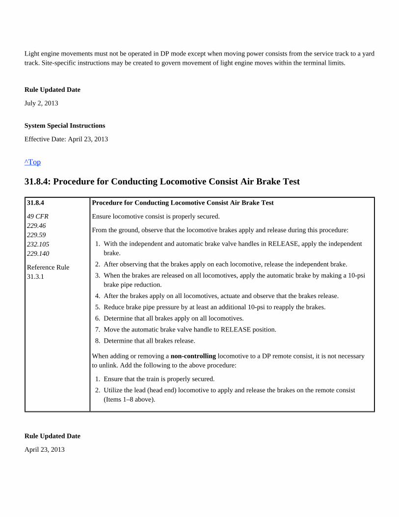
Procedure for Conducting Locomotive Consist Air Brake Test
Ensure locomotive consist is properly secured.
From the ground, observe that the locomotive brakes apply and release during this procedure:
When adding or removing a locomotive to a DP remote consist, it is not necessarynon-controllingto unlink. Add the following to the above procedure:
Rule Updated Date
April 23, 2013
1.
2.
3.
4.
5.
6.
7.
8.
With the independent and automatic brake valve handles in RELEASE, apply the independentbrake.
After observing that the brakes apply on each locomotive, release the independent brake.
When the brakes are released on all locomotives, apply the automatic brake by making a 10-psibrake pipe reduction.
After the brakes apply on all locomotives, actuate and observe that the brakes release.
Reduce brake pipe pressure by at least an additional 10-psi to reapply the brakes.
Determine that all brakes apply on all locomotives.
Move the automatic brake valve handle to RELEASE position.
Determine that all brakes release.
1.
2.
Ensure that the train is properly secured.
Utilize the lead (head end) locomotive to apply and release the brakes on the remote consist(Items 1–8 above).

^Top
31.8.4.1: Light Engine Running Air Brake Test.
31.8.4.1
49 CFR232.105
Reference Rule 31.3.1
31.8.2
Light Engine Running Air Brake Test.
An engineer must perform this air test when:
When test is required, perform the following tasks:
When defects or malfunctions are noted, the condition must be corrected.
A Locomotive Consist Air Brake Test may be made instead of a Light Engine Running Air BrakeTest.
Rule Updated Date
January 20, 2012
^Top
31.8.4.2: Remote Control Light Engine Running Air Brake Test
31.8.4.2
49 CFR232.105
Remote Control Light Engine Running Air Brake Test
A remote control operator must perform this air test unless being relieved and the transmitter isgiven directly to the relieving crew when:
Taking charge of engine not coupled to other equipment and originally made up and tested byother than the assigned engineer,Controlling ends have been changed.
1.
2.
3.
4.
5.
Release the independent brake and open throttle sufficiently to cause locomotive to move.
Close throttle. Locomotive should roll freely. If it does not, check for the cause and correct.
Apply and release the independent brake while speed is low. A speed reduction indicates brakeshave applied.
With the independent brake released, make a light automatic brake pipe pressure reduction. Aspeed reduction indicates brakes have applied.
Actuate and determine that the brakes release. The locomotive should roll freely.
Taking charge of a remote control engine not coupled to other equipment and originally madeup and tested by other than the assigned engineer,orControlling ends have been changed on a remote control consist.

When test is required, perform the following tasks:
When defects or malfunctions are noted, the condition must be corrected.
A Locomotive Consist Air Brake Test may be made instead of a Remote Control Light EngineRunning Air Brake Test.
Note:Belt Pac RCL equipment is not designed to allow for a light engine running air brake test. Alocomotive consist air brake test must be performed.
Rule Updated Date
July 2, 2013
System Special Instructions
Effective Date: April 20, 2012
^Top
31.8.4.3: Electronic Alertness Control Device (Alerter) Test
Procedure for conducting alerter test:
1.
2.
3.
4.
5.
6.
7.
Select direction on the RCT, press either vigilance button then position Speed Selector toCouple Setting to cause locomotive to move.
Verify brakes are released and then position Speed Selector to 10 MPH.
Move Speed Selector to Coast and apply a low setting with the Independent Brake Override. Aspeed reduction indicates brakes have applied.
Release Independent Brake Override and position Automatic Brake Selector to MinimumSetting. Verify that brakes do not apply.
Position Automatic Brake Selector to Light Setting and verify that brakes do not apply.
Position Automatic Brake Selector to Medium Setting. A speed reduction indicates brakes haveapplied.
Position Automatic Brake Selector to Released Setting. The locomotive should roll freely.
1.
2.
3.
4.
5.
Protect locomotive from unintended movement.
Place the automatic and independent brakes in release.
Allow the timing cycle to expire and observe that warning lights and audible alarm function.
Allow the alerter to "time out" and observe:
Recover penalty brake application.
PC or PCS indicator light illuminate.
Reduction in equalizing reservoir pressure.

Rule Updated Date
July 2, 2013
^Top
31.8.5: Starting Procedure
31.8.5 Starting Procedure
Follow this procedure to start a locomotive:
Rule Updated Date
January 20, 2012
^Top
31.8.6: Weak Batteries
31.8.6 Weak Batteries
When a weak battery condition is determined by the Mechanical Department, do the following:
1.
2.
3.
4.
5.
6.
7.
8.
9.
10.
11.
Check the cooling water level.
Check that the governor low oil button, over-speed trip, and low water and crankcase protectivedevices are in the proper positions.
Check that switches or breakers for air conditioning, lights, heaters, refrigerator, and otheraccessories are in the OFF positions.
Ensure that the fuel pump circuit breaker is on.
Check that the engine run and control switches on the engineer's control console are on.
Make sure the Isolation Switch is in the START/STOP/ISOLATE position.
Close the main battery switch.
Prime the engine as indicated on the badge plate.
Crank the engine until the engine starts, but not longer than 20 seconds for EMD locomotivesand 45 seconds for GE locomotives. Allow two minutes between cranking attempts.
After starting, place switches or breakers for air conditioning, lights, heaters, refrigerator, andother accessories in the ON positions, as appropriate.
Check that the air brake system is charged and operative before releasing the hand brake.
Tag locomotives with weak batteries to prevent shutdown until the condition is corrected.Report the condition on engineer electronic inspection report.
Locomotives identified with such tags or other identified mechanical problems that would preventstarting where repair facilities are not available may be left running for no more than seven calendardays.
Rule Updated Date
January 20, 2012
^Top
31.8.7: Locomotive Fuel Conservation and TPA Compliance
31.8.7
Reference Rule
SSI Item 5-C
Glossary
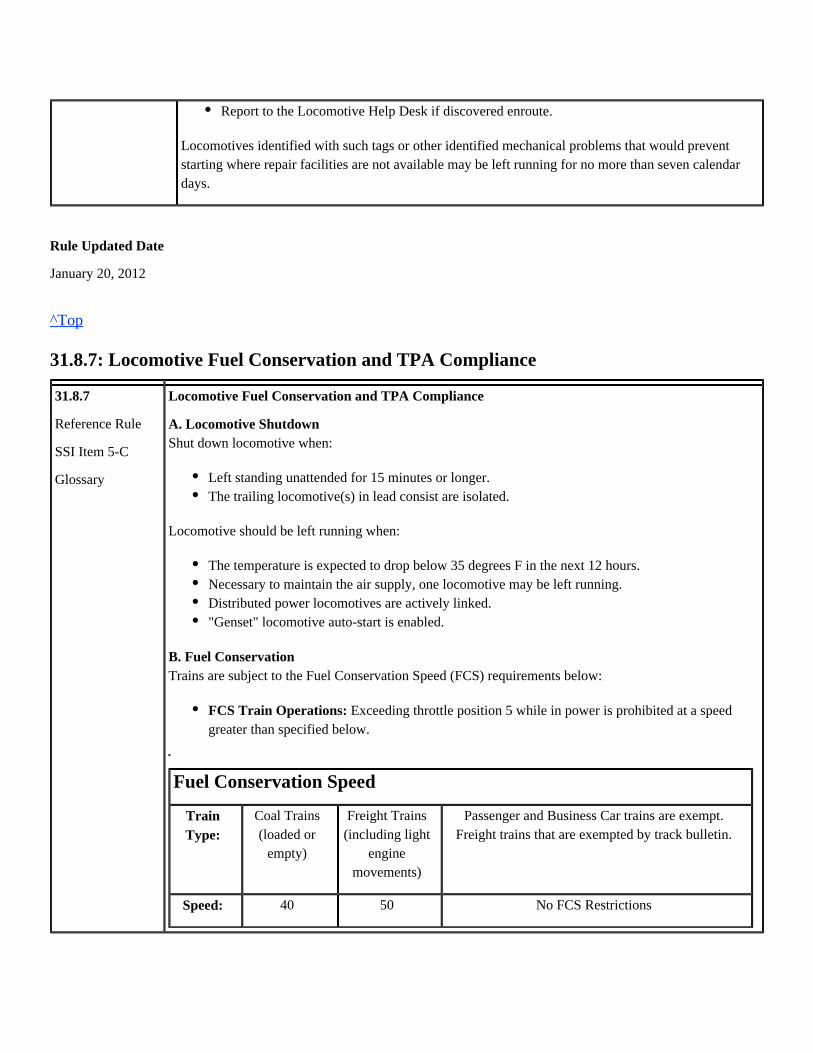
Locomotive Fuel Conservation and TPA Compliance
A. Locomotive ShutdownShut down locomotive when:
Locomotive should be left running when:
B. Fuel ConservationTrains are subject to the Fuel Conservation Speed (FCS) requirements below:
Fuel Conservation Speed
TrainType:
Coal Trains(loaded or
empty)
Freight Trains(including light
enginemovements)
Passenger and Business Car trains are exempt.Freight trains that are exempted by track bulletin.
Speed: 40 50 No FCS Restrictions
Report to the Locomotive Help Desk if discovered enroute.
Left standing unattended for 15 minutes or longer.The trailing locomotive(s) in lead consist are isolated.
The temperature is expected to drop below 35 degrees F in the next 12 hours.Necessary to maintain the air supply, one locomotive may be left running.Distributed power locomotives are actively linked."Genset" locomotive auto-start is enabled.
Exceeding throttle position 5 while in power is prohibited at a speedFCS Train Operations:greater than specified below.

Coal trains may be authorized to operate at FCS 50 by timetable or subdivision general order.
Higher throttle positions may be used, up to and including run 8, to achieve and maintainFCS-authorized speed.
The train dispatcher may cancel fuel conservation speed restrictions.
C. Tons Per Powered Axle (TPA)
Trains must be operated as required by TPA limits for the current crew district as indicated on their TCStrain lists (BC), and not to exceed those limits. Non-working status codes (DG, DB, PD, IB) areassigned to locomotive units which are not to be used for power, in order to comply with TPA limitsand maximize fuel efficiency. Locomotives with non-working status codes on the BC must always beeither isolated or shut down, depending on ambient air temperature, and according to the instructions in31.8.7 Section A.
Each head-end locomotive isolated or shut down for fuel conservation purposes must be identified byplacing a fuel conservation tag on the isolation switch. The lead unit must also be tagged identifying allof the locomotives in the head-end consist that are isolated or dead. Any changes made must be notedon the lead unit's tag.
At each crew change point, inbound engineers must communicate the configuration of their head-endlocomotive consist to the relieving crew, either in person or by using appropriate tags attached toisolation switches. If unable to ascertain in person from an inbound engineer if the head-endlocomotives are set up according to the BC, the outbound engineer must first examine any tags attachedto the isolation switch on the lead unit, and then compare that information with the BC train list for theircrew district.
Adjustments to the head-end consist configuration must only be made as necessary to ensurecompliance with locomotive status codes and crew district TPA limits.
If it is necessary to go through the locomotives in order to release handbrakes, the engineer must verifythat the correct units are running and on line at that time.
Locomotive axles / traction motors must not be cut-out to comply with TPA restrictions. Additionallocomotive(s) may be on line if the engineer determines that the train may stall due to locomotivedefects, not to exceed system or subdivision maximum powered axle limitations. DG units that are usedfor power must be reported using the locomotive inspection reporting process at tie-up.
The controlling unit of each consist, including DP consist(s), must not be manually isolated or shutdown to comply with these instructions. This does not prohibit the isolation or shutdown of other unitsin remote consists.
When calculating TPA/TPDBA, do not round off EPA/EDBA numbers used in making theNote:calculation. After completing the calculation, if the final number is not a whole number, round up theresult to the nearest whole number.
A train has 10,469 tons and three locomotives with a total of 36.3 EPA. The detail trainExample:consist indicates the following TPA limit:
MAXIMUM TPA BETWEEN SX263 AND NX039 IS 430, CURRENT TPA IS 289. If one unit was

isolated weighing 200 tons, the train would then have 24.2 EPA, and TPA will increase to 441. Thisexceeds the maximum TPA for the territory to be operated over. Therefore, all three locomotives mustbe left on line.
Rule Updated Date
July 2, 2013
^Top
31.8.7.1: Shutdown Procedure
31.8.7.1
Reference Rule35.5.1
Shutdown ProcedureFollow this procedure to shut down a locomotive:
Rule Updated Date
July 2, 2013
^Top
31.8.7.2: Prevent Engine Cooling System from Freezing
1.
2.
3.
4.
5.
6.
7.
8.
9.
Make sure hand brake is fully applied if leaving locomotive unattended.
Place generator field switch OFF.
Remove reverser.
Move the engine control switch (isolation switch) to the START/STOP/ISOLATE position.
Shut down engine (EFCO Switch in Locomotive Cab).
Wait 2 minutes.
Open all non-covered accessory switches and circuit breakers on the Engineer's Control Panel. Openall covered circuit breakers in accordance with shutdown sticker on locomotive.
Wait 2 minutes.
Open main battery switch, except:
If locomotive is GE AC Model (i.e. C44AC, C44ACTE, C45ACCTE, etc.) open BCCB circuitbreaker first, wait until the operator screens go blank and green LED extinguishes. Then turnoff the remaining breakers prior to opening the main battery switch.
Main battery switch may be left closed for up to two hours to maintain cab signal link onlocomotives operating in cab signal territory.
Main battery switch may be left closed on RCL to maintain link during short-term securement.

31.8.7.2 Prevent Engine Cooling System from FreezingThe engineer is responsible for protecting locomotives from freeze damage. If an engine dies andcannot be restarted, the engine must be drained if the temperature is below 32 degrees F. Notify thetrain dispatcher.
If the failure is in the distributed power, immediately contact the train dispatcher.
Rule Updated Date
January 20, 2012
^Top

Union Pacific Rules Air Brake and Train Handling Rules
32.0: Securement/Train Operations - Chapter 32
32.0: Securement / Train Operations32.1: Securing Equipment32.1.1: Securement Procedures32.1.2: Securing an Unattended Train or Portion of Train with Locomotive Attached32.1.3: Securing an Unattended Train Before Detaching Locomotives32.1.4: Single Car Securement32.1.5: Securing Specialized Equipment32.1.6: Releasing Hand Brakes32.2: Securing Locomotives32.2.1: Unattended Locomotive(s)32.2.1.1: Securing Locomotive Cab Doors32.2.2: Separating Locomotives32.3: Train Line32.3.1: Undesired Emergency Resulting in Train Separation32.3.2: Coupling Brake Pipe Connections32.3.3: Coupling to Opposite End of Cars32.4: Inclement Weather32.4.1: Required Air Brake Test During Inclement Weather32.5: Overcharge32.5.1: Reducing Pressure in Overcharged Train Brake Systems32.6: Flat Spots32.6.1: Reporting Flat Spots32.7: Air Brake Operation32.7.1: Air Brakes Not Operating Properly32.7.2: Sticking Brakes32.7.3: Procedure to Cut-Out Control Valve and/or Bleeding Off Car32.7.4: Placement of Cars with Cut-Out Air Brake Equipment32.8: Setting Out Cars32.8.1: Setting Out Defective Cars32.9: Telemetry32.9.1: Emergency Application Capability from Rear of Train32.9.2: Installation32.9.3: Arming HEU/EOT32.9.4: Testing HEU/EOT
32.0: Securement / Train Operations
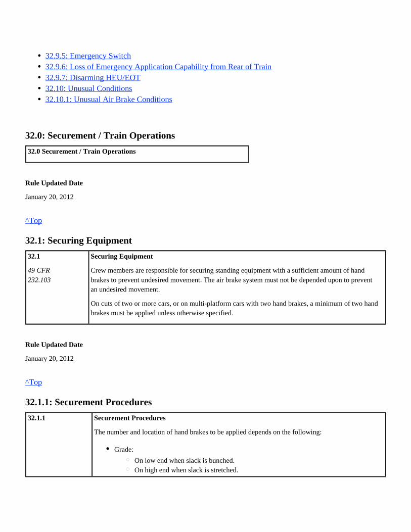
32.0 Securement / Train Operations
Rule Updated Date
January 20, 2012
^Top
32.1: Securing Equipment
32.1
49 CFR232.103
Securing Equipment
Crew members are responsible for securing standing equipment with a sufficient amount of handbrakes to prevent undesired movement. The air brake system must not be depended upon to preventan undesired movement.
On cuts of two or more cars, or on multi-platform cars with two hand brakes, a minimum of two handbrakes must be applied unless otherwise specified.
Rule Updated Date
January 20, 2012
^Top
32.1.1: Securement Procedures
32.1.1 Securement Procedures
The number and location of hand brakes to be applied depends on the following:
32.9.5: Emergency Switch32.9.6: Loss of Emergency Application Capability from Rear of Train32.9.7: Disarming HEU/EOT32.10: Unusual Conditions32.10.1: Unusual Air Brake Conditions
Grade:
On low end when slack is bunched.On high end when slack is stretched.
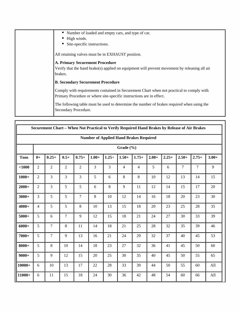
All retaining valves must be in EXHAUST position.
A. Primary Securement ProcedureVerify that the hand brake(s) applied on equipment will prevent movement by releasing all airbrakes.
B. Secondary Securement Procedure
Comply with requirements contained in Securement Chart when not practical to comply withPrimary Procedure or where site-specific instructions are in effect.
The following table must be used to determine the number of brakes required when using theSecondary Procedure.
Securement Chart – When Not Practical to Verify Required Hand Brakes by Release of Air Brakes
Number of Applied Hand Brakes Required
Grade (%)
Tons 0+ 0.25+ 0.5+ 0.75+ 1.00+ +1.25 1.50+ 1.75+ 2.00+ 2.25+ 2.50+ 2.75+ 3.00+
<1000 2 2 2 2 3 3 4 4 5 6 7 7 9
1000+ 2 3 3 3 5 6 8 8 10 12 13 14 15
2000+ 2 3 5 5 6 8 9 11 12 14 15 17 20
3000+ 3 5 5 7 8 10 12 14 16 18 20 23 30
4000+ 4 5 5 8 10 13 15 18 20 23 25 28 35
5000+ 5 6 7 9 12 15 18 21 24 27 30 33 39
6000+ 5 7 8 11 14 18 21 25 28 32 35 39 46
7000+ 5 7 9 13 16 21 24 29 32 37 40 45 53
8000+ 5 8 10 14 18 23 27 32 36 41 45 50 60
9000+ 5 9 12 15 20 25 30 35 40 45 50 55 65
10000+ 6 10 13 17 22 28 33 39 44 50 55 60 All
11000+ 6 11 15 18 24 30 36 42 48 54 60 66 All
Number of loaded and empty cars, and type of car.High winds.Site-specific instructions.

12000+ 7 14 16 20 26 33 39 46 52 59 65 72 All
13000+ 8 15 17 22 28 35 42 49 56 63 70 All All
14000+ 8 15 20 23 30 38 45 53 60 68 75 All All
15000+ 9 16 22 24 32 40 48 56 64 72 80 All All
16000+ 10 18 24 26 34 43 51 60 68 77 85 All All
17000+ 10 20 26 28 36 45 54 63 72 81 90 All All
Rule Updated Date
January 20, 2012
^Top
32.1.2: Securing an Unattended Train or Portion of Train with Locomotive Attached
32.1.2
Reference Rule7.632.1.132.1.3
Securing an Unattended Train or Portion of Train with Locomotive Attached
To secure a train or a portion of a train with the lead locomotive consist attached, perform the stepsbelow:
Rule Updated Date
July 2, 2013
System Special Instructions
Effective Date: January 25, 2012
^Top
32.1.3: Securing an Unattended Train Before Detaching Locomotives
32.1.3 Securing an Unattended Train Before Detaching Locomotives
1.
2.
3.
Determine the minimum number of hand brakes required to secure a train. Count locomotivehand brakes toward the total hand brakes required.
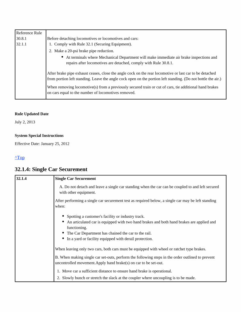
Comply with Rule 32.1 (Securing Equipment).
Complete Train and Locomotive checklist.
Reference Rule30.8.132.1.1
Before detaching locomotives or locomotives and cars:
After brake pipe exhaust ceases, close the angle cock on the rear locomotive or last car to be detachedfrom portion left standing. Leave the angle cock open on the portion left standing. (Do not bottle the air.)
When removing locomotive(s) from a previously secured train or cut of cars, tie additional hand brakeson cars equal to the number of locomotives removed.
Rule Updated Date
July 2, 2013
System Special Instructions
Effective Date: January 25, 2012
^Top
32.1.4: Single Car Securement
32.1.4 Single Car Securement
A. Do not detach and leave a single car standing when the car can be coupled to and left securedwith other equipment.
After performing a single car securement test as required below, a single car may be left standingwhen:
When leaving only two cars, both cars must be equipped with wheel or ratchet type brakes.
B. When making single car set-outs, perform the following steps in the order outlined to preventuncontrolled movement.Apply hand brake(s) on car to be set-out.
1.
2.
Comply with Rule 32.1 (Securing Equipment).
Make a 20-psi brake pipe reduction.
At terminals where Mechanical Department will make immediate air brake inspections andrepairs after locomotives are detached, comply with Rule 30.8.1.
Spotting a customer's facility or industry track.An articulated car is equipped with two hand brakes and both hand brakes are applied andfunctioning.The Car Department has chained the car to the rail.In a yard or facility equipped with derail protection.
1.
2.
3.
Move car a sufficient distance to ensure hand brake is operational.
Slowly bunch or stretch the slack at the coupler where uncoupling is to be made.
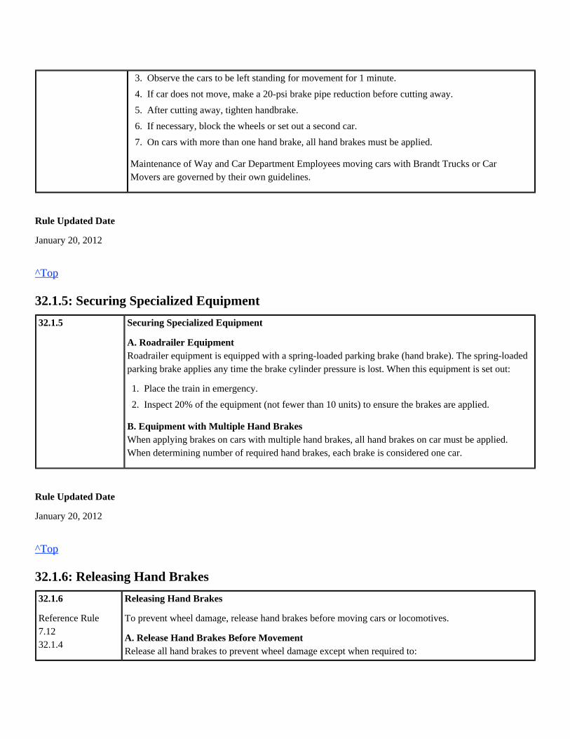
Maintenance of Way and Car Department Employees moving cars with Brandt Trucks or CarMovers are governed by their own guidelines.
Rule Updated Date
January 20, 2012
^Top
32.1.5: Securing Specialized Equipment
32.1.5 Securing Specialized Equipment
A. Roadrailer EquipmentRoadrailer equipment is equipped with a spring-loaded parking brake (hand brake). The spring-loadedparking brake applies any time the brake cylinder pressure is lost. When this equipment is set out:
B. Equipment with Multiple Hand BrakesWhen applying brakes on cars with multiple hand brakes, all hand brakes on car must be applied.When determining number of required hand brakes, each brake is considered one car.
Rule Updated Date
January 20, 2012
^Top
32.1.6: Releasing Hand Brakes
32.1.6
Reference Rule7.1232.1.4
Releasing Hand Brakes
To prevent wheel damage, release hand brakes before moving cars or locomotives.
A. Release Hand Brakes Before MovementRelease all hand brakes to prevent wheel damage except when required to:
3.
4.
5.
6.
7.
Observe the cars to be left standing for movement for 1 minute.
If car does not move, make a 20-psi brake pipe reduction before cutting away.
After cutting away, tighten handbrake.
If necessary, block the wheels or set out a second car.
On cars with more than one hand brake, all hand brakes must be applied.
1.
2.
Place the train in emergency.
Inspect 20% of the equipment (not fewer than 10 units) to ensure the brakes are applied.

When releasing hand brakes, check for slack and white paint showing on chain when equipped, and atleast three additional hand brakes beyond the last applied hand brake.
If a hand brake is difficult to release:
If the hand brake cannot be released using the above method, do not move the car except to set it out.The car must be watched during the entire movement to set out, and limit speed to 5 MPH. Reportdefect to Mechanical Help Desk/Dispatcher.
B. Controlling SlackCharge air brake system before releasing hand brakes. On ascending grade, do not release all handbrakes until it is known that slack is stretched.
Rule Updated Date
July 2, 2013
^Top
32.2: Securing Locomotives
32.2 Securing Locomotives
Rule Updated Date
January 20, 2012
^Top
32.2.1: Unattended Locomotive(s)
32.2.1
49 CFR232.103
Unattended Locomotive(s) When securing engine:
Control slack.Control speed while making gravity switch move.Test hand brake.
Charge the air brake system.Make a full service or emergency application.Release the hand brake.
1.
2.
3.
Place throttle in idle.
Place transition handle (if equipped) in OFF position.
Reference Rule32.1.131.8.735.5.1
Exceptions:
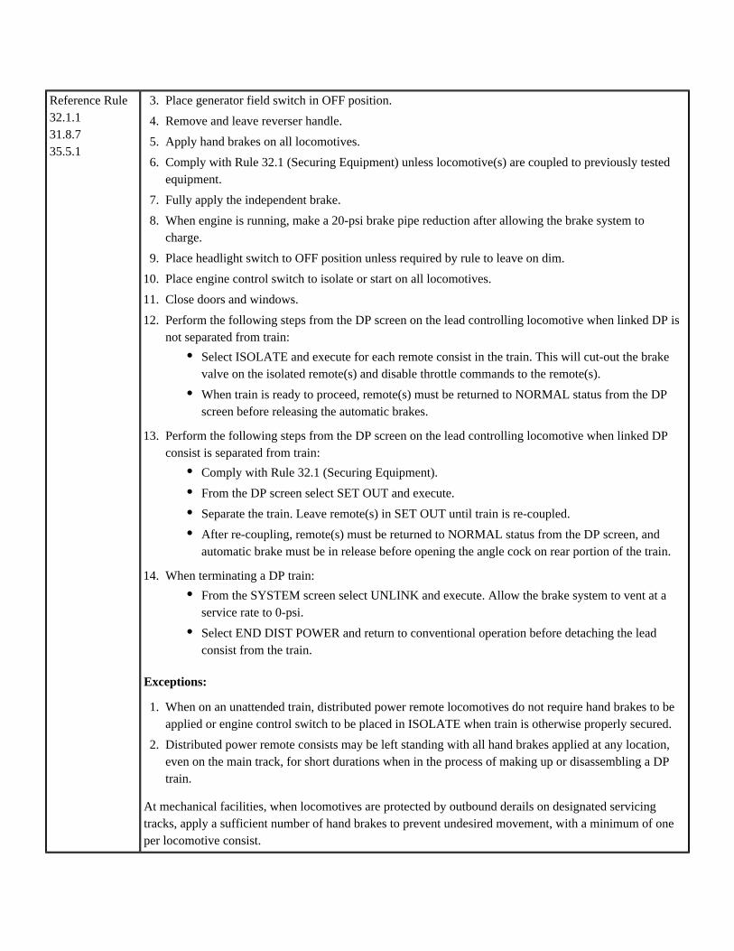
At mechanical facilities, when locomotives are protected by outbound derails on designated servicingtracks, apply a sufficient number of hand brakes to prevent undesired movement, with a minimum of oneper locomotive consist.
3.
4.
5.
6.
7.
8.
9.
10.
11.
12.
13.
14.
Place generator field switch in OFF position.
Remove and leave reverser handle.
Apply hand brakes on all locomotives.
Comply with Rule 32.1 (Securing Equipment) unless locomotive(s) are coupled to previously testedequipment.
Fully apply the independent brake.
When engine is running, make a 20-psi brake pipe reduction after allowing the brake system tocharge.
Place headlight switch to OFF position unless required by rule to leave on dim.
Place engine control switch to isolate or start on all locomotives.
Close doors and windows.
Perform the following steps from the DP screen on the lead controlling locomotive when linked DP isnot separated from train:
Perform the following steps from the DP screen on the lead controlling locomotive when linked DPconsist is separated from train:
When terminating a DP train:
Select ISOLATE and execute for each remote consist in the train. This will cut-out the brakevalve on the isolated remote(s) and disable throttle commands to the remote(s).
When train is ready to proceed, remote(s) must be returned to NORMAL status from the DPscreen before releasing the automatic brakes.
Comply with Rule 32.1 (Securing Equipment).
From the DP screen select SET OUT and execute.
Separate the train. Leave remote(s) in SET OUT until train is re-coupled.
After re-coupling, remote(s) must be returned to NORMAL status from the DP screen, andautomatic brake must be in release before opening the angle cock on rear portion of the train.
From the SYSTEM screen select UNLINK and execute. Allow the brake system to vent at aservice rate to 0-psi.
Select END DIST POWER and return to conventional operation before detaching the leadconsist from the train.
1.
2.
When on an unattended train, distributed power remote locomotives do not require hand brakes to beapplied or engine control switch to be placed in ISOLATE when train is otherwise properly secured.
Distributed power remote consists may be left standing with all hand brakes applied at any location,even on the main track, for short durations when in the process of making up or disassembling a DPtrain.

Additional securement guidelines for unattended locomotives not coupled to other equipment:
Rule Updated Date
July 2, 2013
^Top
32.2.1.1: Securing Locomotive Cab Doors
32.2.1.1 Securing Locomotive Cab DoorsA. Unattended Locomotives
Controlling locomotives equipped with door locks and latches must be locked to prevent cab entry before leavingconsist unattended outside of yards or terminals. Trailing locomotives may be left unlocked.
Secure controlling locomotive in consist as follows:
Union Pacific locomotive padlocks require a double cut key, number D575, to operate. All crew members arerequired to have this key available while on duty.
On trains and locomotives that will be delivered to foreign line railroads or interchange locations, crewmembers mustleave locomotive cabs unlocked.
B. Attended Locomotives
Ensure cab doors on lead consist are unlocked when locomotives are attended except when necessary to preventunauthorized entry.
C. Distributed Power
Distributed power locomotives must remain unlocked.
Rule Updated Date
July 2, 2013
Must not be left unattended on a main track. However, when necessary to switch a locomotive in aconsist (reposition, wye, etc.), a properly secured locomotive may be left unattended if crewremains in the area performing the switch move.Must have all hand brakes applied. Release locomotive brakes to determine hand brakes willprevent movement. Fully apply independent brake and make a 20 psi automatic brake pipereduction.
Latch/lock rear cab doors from inside cab, then exit and lock front door using the slide bolt padlock.

General Order
Effective Date: July 2, 2013
^Top
32.2.2: Separating Locomotives
32.2.2 Separating Locomotives
When separating locomotives, do the following:
test link
Rule Updated Date
July 2, 2013
^Top
32.3: Train Line
32.3 Train Line
Rule Updated Date
January 20, 2012
^Top
32.3.1: Undesired Emergency Resulting in Train Separation
1.
2.
3.
4.
5.
6.
7.
8.
Apply hand brakes on locomotives to be cut away from.
Reposition walkway end platforms and safety chains to create a continuous barrier at ends oflocomotives.
Disconnect MU cables.
Plug the MU cables into a dummy receptacle.
Close cutout and angle cocks.
Cut-in and fully apply independent and automatic air brakes.
Separate locomotives, allowing hose connections to pull apart with movement of locomotive.
Attach air hoses to the dummy couplings or place them in the pockets.
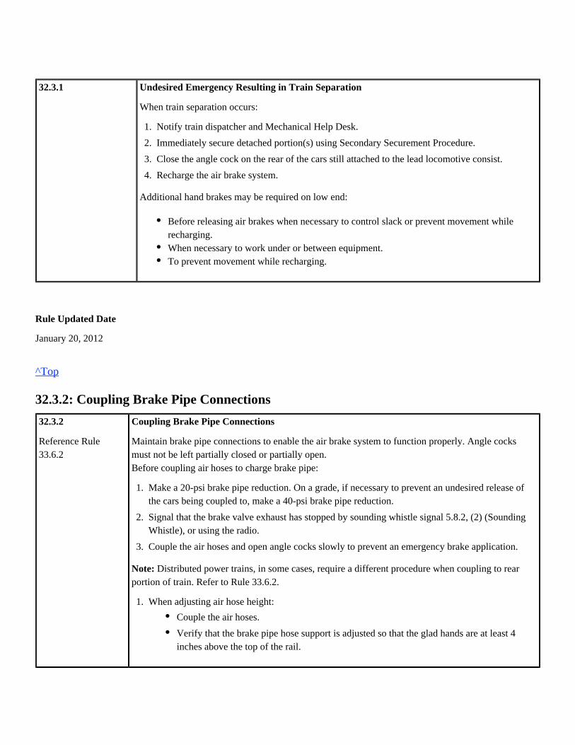
32.3.1 Undesired Emergency Resulting in Train Separation
When train separation occurs:
Additional hand brakes may be required on low end:
Rule Updated Date
January 20, 2012
^Top
32.3.2: Coupling Brake Pipe Connections
32.3.2
Reference Rule33.6.2
Coupling Brake Pipe Connections
Maintain brake pipe connections to enable the air brake system to function properly. Angle cocksmust not be left partially closed or partially open.Before coupling air hoses to charge brake pipe:
Distributed power trains, in some cases, require a different procedure when coupling to rearNote:portion of train. Refer to Rule 33.6.2.
1.
2.
3.
4.
Notify train dispatcher and Mechanical Help Desk.
Immediately secure detached portion(s) using Secondary Securement Procedure.
Close the angle cock on the rear of the cars still attached to the lead locomotive consist.
Recharge the air brake system.
Before releasing air brakes when necessary to control slack or prevent movement whilerecharging.When necessary to work under or between equipment.To prevent movement while recharging.
1.
2.
3.
Make a 20-psi brake pipe reduction. On a grade, if necessary to prevent an undesired release ofthe cars being coupled to, make a 40-psi brake pipe reduction.
Signal that the brake valve exhaust has stopped by sounding whistle signal 5.8.2, (2) (SoundingWhistle), or using the radio.
Couple the air hoses and open angle cocks slowly to prevent an emergency brake application.
1. When adjusting air hose height:
Couple the air hoses.
Verify that the brake pipe hose support is adjusted so that the glad hands are at least 4inches above the top of the rail.

Rule Updated Date
January 20, 2012
^Top
32.3.3: Coupling to Opposite End of Cars
32.3.3
Reference Rule32.1
Coupling to Opposite End of CarsWhen a locomotive will immediately run-around or couple to cars at the opposite end, first complywith the following:
Do not bottle air or maintain air pressure in the brake pipe when locomotives are detached or yardair is uncoupled.
Rule Updated Date
January 20, 2012
^Top
32.4: Inclement Weather
32.4 Inclement Weather
Rule Updated Date
January 20, 2012
^Top
32.4.1: Required Air Brake Test During Inclement Weather
32.4.1
49 CFR232.107
Required Air Brake Test During Inclement Weather
During inclement weather conditions that may cause snow or ice build up to occur between brakeshoes and wheels, brake applications must be performed periodically to ensure proper braking effort isbeing provided.
Make a 20-psi brake pipe reduction before cutting away from cars.Allow air brake system to go into emergency.Wait one minute.Close angle cock on the standing portion of the train.

To allow any accumulation of ice or snow to melt from brake shoes before braking is necessary, theengineer must make a brake pipe reduction sufficiently in advance of locations where train will berequired to:
or
If brakes do not provide sufficient braking effort, stop train immediately using an emergency brakeapplication, if necessary. Train must not proceed except as instructed by proper authority.
Rule Updated Date
January 20, 2012
^Top
32.5: Overcharge
32.5 Overcharge
Rule Updated Date
January 20, 2012
^Top
32.5.1: Reducing Pressure in Overcharged Train Brake Systems
32.5.1 Reducing Pressure in Overcharged Train Brake Systems
To reduce pressure in an overcharged train brake system, do the following:
Reduce speed.Operate at Restricted Speed.Stop.
Before cresting grade.
1.
2.
3.
4.
Adjust the regulating valve to the required pressure.
Make a full service brake pipe reduction.
Wait at least 30 seconds after the brake pipe exhaust stops. Move the automatic brake handle torelease, and charge the system to the required pressure.
An emergency application may be made to correct the condition.

Rule Updated Date
January 20, 2012
^Top
32.6: Flat Spots
32.6 Flat Spots
Rule Updated Date
January 20, 2012
^Top
32.6.1: Reporting Flat Spots
32.6.1
49 CFR 215.103
229.75
Reporting Flat Spots
While inspecting car and locomotive wheels, measure and report flat wheels to proper authority andMechanical Help Desk when length of flat area exceeds 1 inch.
If wheel has a flat spot more than 2-1/2 inches long or wheel has adjoining flat spots that are each atleast 2 inches long, the equipment must not be moved faster than 10 MPH and set out at first availablepoint.
Rule Updated Date
January 20, 2012
^Top
32.7: Air Brake Operation
32.7 Air Brake Operation
Rule Updated Date
January 20, 2012

^Top
32.7.1: Air Brakes Not Operating Properly
32.7.1
Reference Rule30.7.1
Air Brakes Not Operating ProperlyIf the train air brake system is not operating properly, stop the train immediatelyand:
Rule Updated Date
January 20, 2012
^Top
32.7.2: Sticking Brakes
32.7.2
Reference Rule30.2.2
Sticking Brakes
To minimize the possibility of sticking brakes, comply with the following:
When brakes do not properly release:
If air brake devices are cut-out enroute, notify train dispatcher and Mechanical Help Desk.
1.
2.
Inspect the air brakes to identify and correct the problem.
Before proceeding, conduct an Application and Release test.
1.
2.
To prevent overcharge, when cars are placed on rear portion of a train, the engineer handling therear portion must make a full service brake application before angle cocks are opened.
When a running release of train brakes is to be made and operating conditions permit, increasethe brake pipe reduction to at least 10-psi and allow brake pipe exhaust to stop before releasingbrakes.
1.
2.
3.
4.
Stop the train as soon as possible.
Determine why the brake(s) did not release and correct if possible.
Inspect for:
Inspect car before departing for wheel defects, and set out car if necessary.
Hand brakes applied.
Retaining valve not in EXHAUST.
Leak in the air brake system.
Defective control valve.

Rule Updated Date
January 20, 2012
^Top
32.7.3: Procedure to Cut-Out Control Valve and/or Bleeding Off Car
32.7.3 Procedure to Cut-Out Control Valve and/or Bleeding Off Car
Cut-out control valves on defective cars as follows:
Bleed off cars only when:
Rule Updated Date
January 20, 2012
^Top
32.7.4: Placement of Cars with Cut-Out Air Brake Equipment
32.7.4
49 CFR232.15
Placement of Cars with Cut-Out Air Brake Equipment
Follow these requirements when air brake devices must be cut-out:
Rear Car Brakes
The rear car of a train must have operative air brakes. If rear car air brakes become defective enroute,set car out at first available location or reposition car in train.
1.
2.
Close the branch pipe cutout cock.
When cutting out a control valve, drain the air reservoirs completely by operating the brakecylinder release valve.
Repairing the brake system on a car.Cutting out the brakes on a defective car.Switching.
Make sure no more than two consecutive air brake devices have been cut-out in a train.If necessary to cut-out a third consecutive air brake device, separate it from the other two carswith cut-out brakes by at least one car with operative brakes.If one air brake device/control valve is cut-out on a car with multiple control valves, considerthe remaining brakes on that car to be operative.

If the brake pipe on the disabled car is broken, the car with a broken brake pipe must beNote:handled to set out location with brake pipe pressure in air hoses between the car ahead and thedisabled car.
Rule Updated Date
January 20, 2012
^Top
32.8: Setting Out Cars
32.8 Setting Out Cars
Rule Updated Date
January 20, 2012
^Top
32.8.1: Setting Out Defective Cars
32.8.1
49 CFR232.215
Setting Out Defective Cars
Set out a defective car whenever it cannot be safely moved to the next repair location. Whendefective car must be set out, do the following:
The defective car must be properly tagged.
Rule Updated Date
January 20, 2012
^Top
32.9: Telemetry
32.9 Telemetry
1.
2.
3.
Report to the train dispatcher and Mechanical Help Desk.
Set out where repair crew can access car.
If an overheated wheel or journal is involved, inspect the car for signs of fire before departing.

Rule Updated Date
January 20, 2012
^Top
32.9.1: Emergency Application Capability from Rear of Train
32.9.1
49 CFR 232.407
Reference Rule31.8.3
Emergency Application Capability from Rear of Train
A. Requirements
Trains must be operated with the ability to place the train in emergency from the rear. The followingtrains are exempt from the requirement of this rule:
In the application of this rule, locals, road switchers, and work trains are defined as a train that doesnot exceed 4,000 trailing tons and travels over a distance that can normally be operated by a singlecrew in a single tour of duty.
B. Providing Emergency Application Capability from Rear of Train
Any one of the following methods fulfills the requirement to provide emergency applicationcapability from the rear of the train:
Rule Updated Date
January 20, 2012
^Top
32.9.2: Installation
Passenger and Commuter Trains.Light engine consist with 8 or fewer units.Locals, road switchers, and work trains that do not operate on mountain grades.Trains that do not exceed 30 MPH and do not operate in heavy grade or mountain gradeterritory.
An operable, two-way, end-of-train telemetry system (HEU/EOT), which must be armed andtested at point of installation.Distributed power placed on rear of train.Trains with a manned helper, caboose/shoving platform or passenger equipment at the rear oftrain equipped with an emergency brake valve and manned by an employee equipped withtwo-way radio communication with the engineer at head end of train.
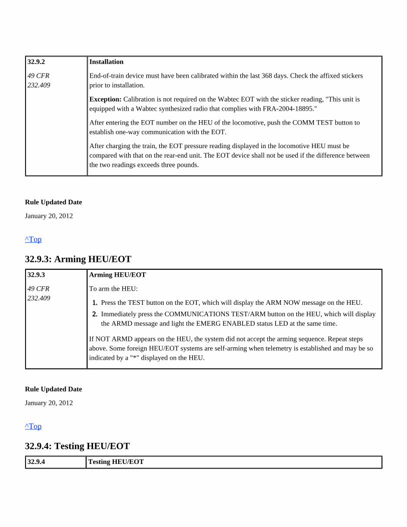
32.9.2
49 CFR232.409
Installation
End-of-train device must have been calibrated within the last 368 days. Check the affixed stickersprior to installation.
Calibration is not required on the Wabtec EOT with the sticker reading, "This unit isException:equipped with a Wabtec synthesized radio that complies with FRA-2004-18895."
After entering the EOT number on the HEU of the locomotive, push the COMM TEST button toestablish one-way communication with the EOT.
After charging the train, the EOT pressure reading displayed in the locomotive HEU must becompared with that on the rear-end unit. The EOT device shall not be used if the difference betweenthe two readings exceeds three pounds.
Rule Updated Date
January 20, 2012
^Top
32.9.3: Arming HEU/EOT
32.9.3
49 CFR232.409
Arming HEU/EOT
To arm the HEU:
If NOT ARMD appears on the HEU, the system did not accept the arming sequence. Repeat stepsabove. Some foreign HEU/EOT systems are self-arming when telemetry is established and may be soindicated by a "*" displayed on the HEU.
Rule Updated Date
January 20, 2012
^Top
32.9.4: Testing HEU/EOT
32.9.4 Testing HEU/EOT
1.
2.
Press the TEST button on the EOT, which will display the ARM NOW message on the HEU.
Immediately press the COMMUNICATIONS TEST/ARM button on the HEU, which will displaythe ARMD message and light the EMERG ENABLED status LED at the same time.
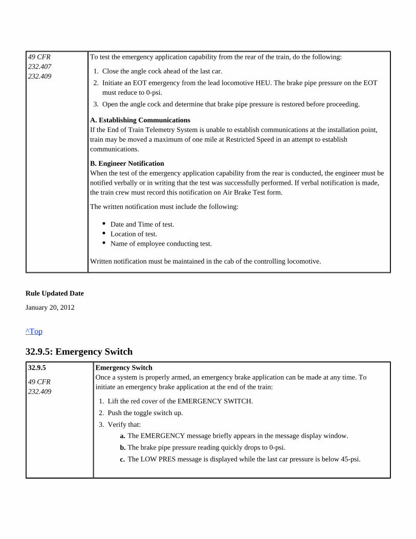
49 CFR 232.407
232.409
To test the emergency application capability from the rear of the train, do the following:
A. Establishing CommunicationsIf the End of Train Telemetry System is unable to establish communications at the installation point,train may be moved a maximum of one mile at Restricted Speed in an attempt to establishcommunications.
B. Engineer NotificationWhen the test of the emergency application capability from the rear is conducted, the engineer must benotified verbally or in writing that the test was successfully performed. If verbal notification is made,the train crew must record this notification on Air Brake Test form.
The written notification must include the following:
Written notification must be maintained in the cab of the controlling locomotive.
Rule Updated Date
January 20, 2012
^Top
32.9.5: Emergency Switch
32.9.5
49 CFR232.409
Emergency SwitchOnce a system is properly armed, an emergency brake application can be made at any time. Toinitiate an emergency brake application at the end of the train:
1.
2.
3.
Close the angle cock ahead of the last car.
Initiate an EOT emergency from the lead locomotive HEU. The brake pipe pressure on the EOTmust reduce to 0-psi.
Open the angle cock and determine that brake pipe pressure is restored before proceeding.
Date and Time of test.Location of test.Name of employee conducting test.
1.
2.
3.
Lift the red cover of the EMERGENCY SWITCH.
Push the toggle switch up.
Verify that:
c.
b.
a. The EMERGENCY message briefly appears in the message display window.
The brake pipe pressure reading quickly drops to 0-psi.
The LOW PRES message is displayed while the last car pressure is below 45-psi.
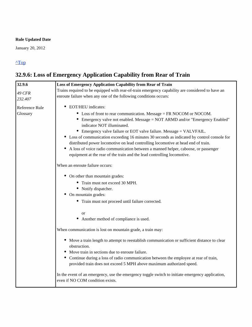
Rule Updated Date
January 20, 2012
^Top
32.9.6: Loss of Emergency Application Capability from Rear of Train
32.9.6
49 CFR232.407
Reference RuleGlossary
Loss of Emergency Application Capability from Rear of TrainTrains required to be equipped with rear-of-train emergency capability are considered to have anenroute failure when any one of the following conditions occurs:
When an enroute failure occurs:
When communication is lost on mountain grade, a train may:
In the event of an emergency, use the emergency toggle switch to initiate emergency application,even if NO COM condition exists.
EOT/HEU indicates:
Loss of communication exceeding 16 minutes 30 seconds as indicated by control console fordistributed power locomotive on lead controlling locomotive at head end of train.A loss of voice radio communication between a manned helper, caboose, or passengerequipment at the rear of the train and the lead controlling locomotive.
Loss of front to rear communication. Message = FR NOCOM or NOCOM.Emergency valve not enabled. Message = NOT ARMD and/or "Emergency Enabled"indicator NOT illuminated.Emergency valve failure or EOT valve failure. Message = VALVFAIL.
On other than mountain grades:
On mountain grades:
Train must not exceed 30 MPH.Notify dispatcher.
Train must not proceed until failure corrected.
orAnother method of compliance is used.
Move a train length to attempt to reestablish communication or sufficient distance to clearobstruction.Move train in sections due to enroute failure.Continue during a loss of radio communication between the employee at rear of train,provided train does not exceed 5 MPH above maximum authorized speed.

Rule Updated Date
January 20, 2012
^Top
32.9.7: Disarming HEU/EOT
32.9.7 Disarming HEU/EOTWhen a two-way EOT armed to a HEU are to be separated or when changing either an EOT or HEUenroute, the HEU must be disarmed as outlined below:
GE locomotives with screens displaying "Armed Other" indicate the HEU was not disarmed from thelast two-way EOT utilized. This condition can be corrected by either of two methods:
Rule Updated Date
January 20, 2012
^Top
32.10: Unusual Conditions
32.10 Unusual Conditions
Rule Updated Date
January 20, 2012
^Top
1.
2.
3.
Set the HEU ID code to 00000, or follow the disarm procedures on the electronic display.
Press the COMMUNICATIONS TEST/ARM button.
Verify that the HEU displays EMERG DISABLED.
Enter the EOT number of the last EOT, and disarm as prompted by the EOT screen display.
orIf last EOT identifying number is not known, HEU may be disarmed by arming the EOT byentering a valid EOT number. Push test button on EOT, then depress "Arm Now" button thatwill briefly appear in the lower right corner of the EOT screen.

32.10.1: Unusual Air Brake Conditions
32.10.1 Unusual Air Brake Conditions
Follow this process when unusual air brake conditions exist:
Rule Updated Date
January 20, 2012
^Top
1.
2.
3.
4.
Train must be stopped, secured, and inspected.
Notify the Dispatcher/Mechanical Help Desk.
The Dispatcher must then notify the appropriate operating manager for the territory.
Manager assisting crew will determine if the train can be moved safely or if it must be held forinspection.
Union Pacific Rules Air Brake and Train Handling Rules
33.0: Distributed Power and Manned Helper Chapter 33
33.0: Distributed Power and Manned Helper Requirements
33.0: Distributed Power and Manned Helper Requirements33.1: Distributed Power Requirements33.1.1: Employee Familiarization33.1.2: Brake Pipe Communication Test (BP Test)33.1.3: DP Radio Communication Interruption33.2: Remote Consist Unlinked/Shutdown33.2.1: Setting Out Remote Locomotive33.3: Changing from Independent to Synchronous Mode33.3.1: Operating DP Consist in Independent Mode33.3.9.1: High Strength Coupler Identification33.4: Rear Remote Limitation33.4.1: Maximum Locomotives33.5: Descending Grade33.5.1: Distributed Power, Descending Grade Exceeding 1.8%33.6: Manned Helper Requirements33.6.1: Operating Responsibilities with Manned Helper33.6.2: Adding Manned Helper Mid-train or Rear of Train33.6.3: Removing a Mid-train Helper33.6.4: Manned Helper Added to Head End of Non DP Train33.6.5: Manned Helper Removed from Head End of Train33.6.6: Transferring Control of Train Brakes33.7: Process for Set-up and Linking Locomotives for DP Service33.7.1: Conventional Set-up33.7.2: Display Screen and Remote Set-up33.7.3: Set-up Distributed Power Lead33.8: Procedures for Distributed Power Operation33.8.1: Distributed Power Brake Pipe Communication Test (BP TEST)33.8.2: Distributed Power Automated Leakage Test33.8.3: Set-out Function33.8.4: Train Check
33.0 Distributed Power and Manned Helper Requirements
Rule Updated Date
January 20, 2012
^Top
33.1: Distributed Power Requirements
33.1 Distributed Power Requirements
Rule Updated Date
January 20, 2012
^Top
33.1.1: Employee Familiarization
33.1.1 Employee FamiliarizationEmployees who set-up or operate distributed power equipment must comply with the requirementsand instructions for the type of system they will operate.
Rule Updated Date
January 20, 2012
^Top
33.1.2: Brake Pipe Communication Test (BP Test)
33.1.2
Reference Rule 33.8.1
33.8.2
Brake Pipe Communication Test (BP Test)A brake pipe communication test is required when a distributed power train:
Is originally made up following radio link.Any time cars are added between the head consist and any remoteconsist.

Rule Updated Date
January 20, 2012
^Top
33.1.3: DP Radio Communication Interruption
33.1.3
Reference Rule6.23
DP Radio Communication InterruptionDuring a radio communication interruption, keep the train moving, if possible, to a location wherecommunication is restored.
, train may beAfter required train inspection and air flow is at or below 60 CFM on the lead consistmoved to a location where communication may be restored. Remote locomotive brakes will respond tonormal changes in brake pipe pressure, similar to a freight car.
When communication is restored, the remote locomotive automatic brake valve will be cut-out. Theoperator must normalize the controlling remote(s) to return to standard DP operations.
Rule Updated Date
January 20, 2012
^Top
33.2: Remote Consist Unlinked/Shutdown
33.2 Remote Consist Unlinked/Shutdown
C.
B.
A. If communication is interrupted:
When necessary to idle the remote during communication interruption, make a full service brake pipe reduction to signal the affected remote(s) to return to idle. In
:addition
Recovering from Emergency During Communication Interruption
When brake valve is cut-in on remote(s), the last throttle and brake pipe pressurewill be maintained for up to 90 minutes.
If brake valve on remote(s) is cut-out (BV Out), remote locomotives in power willreturn to idle.
Brake valve on remote(s) will automatically cut-out.
Dynamic brake on remote(s) will be maintained at last command untilcommunication is restored.
If necessary to idle dynamic brake, stop and then place train in emergency.
A. Communication Restored

Rule Updated Date
January 20, 2012
^Top
33.2.1: Setting Out Remote Locomotive
33.2.1 Setting Out Remote Locomotive
Set out the remote locomotive or move to the head end of train as directed by dispatcher or properauthority if:
Rule Updated Date
January 20, 2012
^Top
33.3: Changing from Independent to Synchronous Mode
33.3 Changing from Independent to Synchronous Mode
Rule Updated Date
January 20, 2012
^Top
33.3.1: Operating DP Consist in Independent Mode
33.3.1 Operating DP Consist in Independent Mode
When operating distributed power consists in independent mode, do not place consists in synchronousmode until all consists are in the same throttle setting unless cresting a grade using multiple remoteconsists.
Rule Updated Date
Remote consist is unlinked.Controlling remote is shut down due to enroute failure.

January 20, 2012
^Top
33.3.9.1: High Strength Coupler Identification
This rule has been deleted.
Rule Updated Date
April 20, 2012
System Special Instructions
Effective Date: April 20, 2012
^Top
33.4: Rear Remote Limitation
33.4 Rear Remote Limitation
Rule Updated Date
January 20, 2012
^Top
33.4.1: Maximum Locomotives
33.4.1
Reference RuleSSI Item 5-B / 5-C
Maximum LocomotivesA distributed power consist on the rear of a train is limited to no more than two locomotives.However, when necessary to assist distributed power trains with manned helper operations, additionallocomotives may be placed on the rear of the train; powered axle limits must not be exceeded.
Rule Updated Date
January 20, 2012
^Top
33.5: Descending Grade

33.5 Descending Grade
Rule Updated Date
January 20, 2012
^Top
33.5.1: Distributed Power, Descending Grade Exceeding 1.8%
33.5.1 Distributed Power, Descending Grade Exceeding 1.8%When operating distributed power trains with lead consist in dynamic brake and helper(s) in power,do not exceed throttle position 4 on helper consist(s).
Rule Updated Date
January 20, 2012
^Top
33.6: Manned Helper Requirements
33.6 Manned Helper Requirements
Rule Updated Date
January 20, 2012
^Top
33.6.1: Operating Responsibilities with Manned Helper
33.6.1
49 CFR232.219
Operating Responsibilities with Manned HelperComply with these helper operating responsibilities:
The engineer in the lead locomotive is in charge of train movement. Helper engineer must followlead engineer instructions regarding train handling and other operating responsibilities.Helper locomotive engineers must closely observe brake pipe gauge in order to appropriately reactto either a service or emergency brake pipe reduction and control locomotive brakes as necessary.

Rule Updated Date
January 20, 2012
^Top
33.6.2: Adding Manned Helper Mid-train or Rear of Train
33.6.2
49 CFR232.219
Reference Rule30.7.1
Adding Manned Helper Mid-train or Rear of Train
Procedure for Adding Mid-train or Rear Helper:
On DP trains, do not select set out, BV out, or isolate. Leave remote(s) in normal status.
Rule Updated Date
January 20, 2012
^Top
33.6.3: Removing a Mid-train Helper
33.6.3
Engineers must comply with site-specific instructions regarding trains operating with helper(s)when applicable.
1.
2.
When a helper is entrained or coupled at rear of train, before the angle cocks are opened, theengineer on the helper must:
After the helper is placed in the train or coupled at the rear of the train, the engineer of theleading locomotive must:
d.
c.
b.
a. Make a 20-psi brake pipe reduction.
Cut-out the automatic brake valve and place the handle in Handle Off position.
Leave the independent brake valve cut-in.
Couple the brake pipe hoses. Open the brake pipe angle cock on manned locomotive first,and then open angle cock on car or engine.
b.
a. Increase the brake pipe reduction to 20-psi. Observe at least a 5-psi brake pipe reductionat the rear of train as indicated by gauge or device.
Release the train brakes and determine that there is at least a 5-psi brake pipe increase atrear of train as indicated by gauge or device.
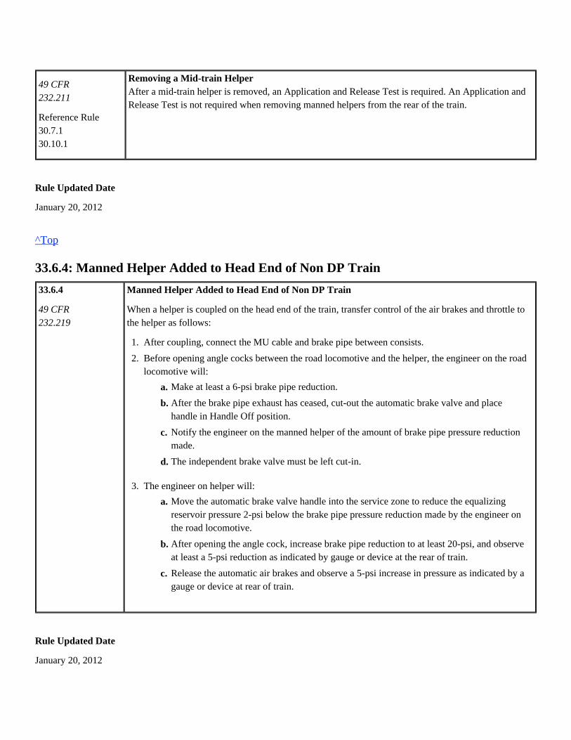
49 CFR232.211
Reference Rule30.7.130.10.1
Removing a Mid-train HelperAfter a mid-train helper is removed, an Application and Release Test is required. An Application andRelease Test is not required when removing manned helpers from the rear of the train.
Rule Updated Date
January 20, 2012
^Top
33.6.4: Manned Helper Added to Head End of Non DP Train
33.6.4
49 CFR232.219
Manned Helper Added to Head End of Non DP Train
When a helper is coupled on the head end of the train, transfer control of the air brakes and throttle tothe helper as follows:
Rule Updated Date
January 20, 2012
1.
2.
3.
After coupling, connect the MU cable and brake pipe between consists.
Before opening angle cocks between the road locomotive and the helper, the engineer on the roadlocomotive will:
The engineer on helper will:
d.
c.
b.
a. Make at least a 6-psi brake pipe reduction.
After the brake pipe exhaust has ceased, cut-out the automatic brake valve and placehandle in Handle Off position.
Notify the engineer on the manned helper of the amount of brake pipe pressure reductionmade.
The independent brake valve must be left cut-in.
c.
b.
a. Move the automatic brake valve handle into the service zone to reduce the equalizingreservoir pressure 2-psi below the brake pipe pressure reduction made by the engineer onthe road locomotive.
After opening the angle cock, increase brake pipe reduction to at least 20-psi, and observeat least a 5-psi reduction as indicated by gauge or device at the rear of train.
Release the automatic air brakes and observe a 5-psi increase in pressure as indicated by agauge or device at rear of train.

^Top
33.6.5: Manned Helper Removed from Head End of Train
33.6.5
49 CFR232.219
Manned Helper Removed from Head End of TrainWhen helper will be detached from the head end of train, do the following:
Rule Updated Date
October 26, 2012
^Top
33.6.6: Transferring Control of Train Brakes
33.6.6 Transferring Control of Train BrakesTransfer control of the train air brakes to other entrained locomotive as follows:
Original controlling locomotive:
New controlling locomotive:
Engineer on helper will make at least a 6-psi brake pipe reduction before detaching.After cutting off helper, road engineer will:
e.
d.
c.
b.
a. Move the automatic brake valve handle to the release position to recover the equalizingreservoir pressure.
Move the automatic brake valve into the service zone to reduce the equalizing reservoirpressure 2-psi below the brake pipe pressure reduction made by the helper locomotiveengineer.
Cut-in the automatic brake.
Increase the brake pipe reduction to 20-psi and observe at least a 5-psi reduction asindicated by a gauge or device at the rear of the train.
Release the automatic air brakes and observe that brake pipe pressure is being restoredby observing a 5-psi increase as indicated by a gauge or device at the rear of the train.
1.
2.
With the train air brakes applied and the brake pipe pressure equalized, cut-out the automatic brakevalve.
If detaching the locomotive, do not close the angle cocks until transfer of the air brakes has beencompleted.

The train must be secured before transferring train air brakes unless both the original and newNote:controlling locomotives are occupied by qualified train service engineers.
Rule Updated Date
January 20, 2012
^Top
33.7: Process for Set-up and Linking Locomotives for DP Service
33.7 Process for Set-up and Linking Locomotives for DP Service
Rule Updated Date
January 20, 2012
^Top
33.7.1: Conventional Set-up
33.7.1 Conventional Set-up
When DP consist has not been previously tested and inspected by mechanical forces for distributed power service, thefollowing tasks must be performed:
1.
2.
3.
4.
5.
If not previously coupled to train, reduce the equalizing pressure 20-psi, and then cut-out theautomatic brake valve before opening angle cocks between locomotive and cars. Open the brakepipe angle cock on the locomotive first, and then slowly open the brake pipe angle cock on the car.
Move the automatic brake valve handle to the release position to recover the equalizing reservoirpressure.
Move the automatic brake valve handle into the service zone until the equalizing reservoir pressureis slightly below brake pipe pressure.
Cut-in the automatic brake valve.
Immediately reduce brake pipe pressure to not less than a 20-psi reduction.
Each consist must be set-up as an individual conventional consist. Each consist must be properly set-up, airtested, and loading.Set equalizing reservoir pressure on controlling locomotives to 90-psi.Clear any air brake computer faults.Connect brake pipe only between consists.Controlling locomotive of each consist must be running during set-up. Override auto stop if necessary.
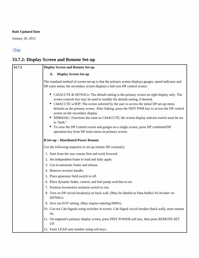
Rule Updated Date
January 20, 2012
^Top
33.7.2: Display Screen and Remote Set-up
33.7.2 Display Screen and Remote Set-up
The standard method of screen set-up is that the primary screen displays gauges, speed indicator andDP main menu; the secondary screen displays a full-size DP control screen:
B.Set-up – Distributed Power Remote
Use the following sequence to set-up remote DP consist(s):
A. Display Screen Set-up
: The default setting is the primary screen on right display only. TheC45ACCTE & SD70ACescreen controls key may be used to modify the default setting, if desired.
: The screen selected by the user to access the initial DP set-up menuC44ACCTE w/IDPdefaults as the primary screen. After linking, press the DIST PWR key to access the DP controlscreen on the secondary display.
: Functions the same as C44ACCTE; the screen display selector switch must be setSD9043ACto "both."To view the DP Control screen and gauges on a single screen, press DP combined/DPoperation key from DP main menu on primary screen.
1.
2.
3.
4.
5.
6.
7.
8.
9.
10.
11.
12.
13.
Start from the rear consist first and work forward.
Set independent brake to lead and fully apply.
Cut-in automatic brake and release.
Remove reverser handle.
Place generator field switch to off.
Place dynamic brake, control, and fuel pump switches to on.
Position locomotive isolation switch to run.
Turn on DP circuit breaker(s) on back wall. (May be labeled as Data Radio) No breaker onSD70ACe.
Zero out EOT setting. (May require entering 00001).
Cut-out Cab Signals using switches in screen. Cab Signal circuit breaker (back wall), must remainon.
On engineer's primary display screen, press DIST POWER soft key, then press REMOTE SETUP.
Enter LEAD unit number using soft keys.

Rule Updated Date
January 20, 2012
^Top
33.7.3: Set-up Distributed Power Lead
33.7.3 Set-up – Distributed Power Lead
Use the following sequence to set-up lead DP consist:
13.
14.
15.
16.
17.
18.
19.
Press the same/opposite direction soft key to set the direction that this locomotive is facingcompared to the lead locomotive. Caution: Do not bypass this step.
Press the DONE or ACCEPT soft key.
Place automatic brake to handle off and independent brake to release. Insert keeper pin inautomatic brake handle if equipped.
Place trailing headlight on dim if rear locomotive.
Pull in mirrors and close windows/doors.
engineer's seat so it does not swivel.Lock the
hand brakes on all locomotives in the remote consist.Release the
1.
2.
3.
4.
5.
6.
7.
8.
9.
10.
11.
12.
13.
independent brake to lead and fully applied.Set the
automatic brake to cut-in and release.Set the
back wall. (May be labeled as Data Radio) Turn on DP circuit breaker(s) on the No breaker onSD70ACe.
isolation switch on back wall to Run.Position the
engineer's primary screen, press the DIST POWER soft key, then press the LEAD SETOn theUP key.
Enter controlling REMOTE unit number.
LINK soft key. System will display "Linked OK" when radio communication isPress theestablished.
System will prompt to enter another controlling remote unit. Enter if train has additional remoteconsist(s).
Press the DONE or ACCEPT key when finished.
Select FTE (Full Tractive Effort) or CTE (Controlled Tractive Effort) as applicable andEXECUTE.
Follow on-screen prompts to recover air. Do not attempt release until "Go to Release" isdisplayed.
Press DIST POWER key on Secondary screen to activate DP Control screen.

Rule Updated Date
January 20, 2012
^Top
33.8: Procedures for Distributed Power Operation
33.8 Procedures for Distributed Power Operation
Rule Updated Date
January 20, 2012
^Top
33.8.1: Distributed Power Brake Pipe Communication Test (BP TEST)
33.8.1 Distributed Power Brake Pipe Communication Test (BP TEST)
The following procedure is required any time cars are added between the lead consist and any remoteconsist:
13.
14.
15.
16.
17.
18.
DP Control screen will indicate flow on each consist. When flow displays less than 20 CFM onall consists or stabilized, press BP TEST key and EXECUTE from System Menu on Primaryscreen.
Apply minimum service when prompted.
System will display "BP Test OK" when complete.
If test fails, release air, recharge train, and attempt test again. Most BP Test failures are due to airflow not being fully stabilized.
LEAKAGE key and EXECUTE from the System Screen on Primary Display toSelect theperform Automated Leakage Test.
DP main menu on the primary display, select the MODE key, and press RUN andFrom theExecute.
1.
2.
3.
flow displays less than 20The DP Control screen will indicate flow on each consist. When theCFM on all consists or the flow has remained stable for 90 seconds, press BP TEST key andEXECUTE from System Menu on the Primary screen.
Apply Minimum Service when prompted.
System will display "BP Test OK" when complete.
If the test fails, recharge the train and re-test. Most BP Test failures are due to air flow notbeing fully stabilized.

Rule Updated Date
January 20, 2012
^Top
33.8.2: Distributed Power Automated Leakage Test
33.8.2 Distributed Power Automated Leakage Test
The following procedure is required when performing a brake pipe leakage test.
Rule Updated Date
January 20, 2012
^Top
33.8.3: Set-out Function
33.8.3
Reference Rule 32.7.2
34.4
Set-out FunctionUse set-out function when trainline is separated between lead consist and remote, including trainseparation. If train is in emergency, comply with step 1 before recovering the air.
Make a 20-psi reduction and allow brake pipe to exhaust, then:
3.
If the test fails after three attempts, inspect the train for excessive leakage or improperlypositioned angle cock(s) before retesting.
1.
2.
3.
4.
5.
6.
On the primary screen, press the system key, then the LEAKAGE key and EXECUTE.
The system will automatically make a 20-psi brake pipe reduction, cut-out brake valves on allconsists, and calculate brake pipe leakage.
Follow the screen prompt when "Apply Full Service Reduction to End Test" is displayed.
The primary screen will display the amount of leakage when test is complete. The leakage testmay take up to 5 minutes.
Release the automatic air brakes when prompted. This will cut-in brake valves.
On primary screen, from DP main menu, select MODE, press RUN key and EXECUTE.
If the train is ready for immediate departure, train check is not required.

Rule Updated Date
January 20, 2012
^Top
33.8.4: Train Check
33.8.4
Reference Rule34.4
Train Check
Perform a train check when a DP train is stopped:
If the "Train Check Fail" message is displayed, comply with one of the following:
Note: Train Check is not required when exceptions contained in Rule 34.4 apply.
1.
2.
3.
4.
5.
6.
7.
8.
On the Secondary Display, press the REMOTE key, then press the SET OUT key andEXECUTE. The selected remote is highlighted on display. Repeat the process if more than oneremote consist is set out.
Verify "Set Out" appears on the remote status.
Separate train. A red PCS indication should begin flashing above the remote display uponseparation.
Make switching moves as needed, and re-couple to train when finished. Do not open the anglecock.
On the Remote Screen on Secondary Display, press the NORMAL key and EXECUTE.
Verify that the remote status on display changes from "Set Out" to "Normal."
The automatic brake must be released before angle cock is opened or train will go intoemergency.
Slowly open the angle cock to rear portion of train. Brake valve (BV) will cut-in on remote whena brake pipe pressure increase is sensed.
1.
2.
A BP reduction of at least 10-psi must be in effect before the TRAIN CHECK key will display.On the Primary screen from the DP Main menu, select SYSTEM, then press TRAIN CHECK andEXECUTE.
Release the brakes when ready to depart. "Train Check OK" message should display in less thanone minute.
Repeat Train Check with brake pipe reduction greater than 10-psi.Perform a manual train check by selecting BV OUT on Remote Screen, then select NORMALand EXECUTE. Then release the automatic reduction. If the remote BV cuts in, this satisfiesthe Train Check requirement.If the test fails three times, inspect the train for closed angle cock(s).

Rule Updated Date
January 20, 2012
^Top

Union Pacific Rules Air Brake and Train Handling Rules
34.0: Train Handling Chapter 34
34.0: Train Handling34.1: Train Handling Responsibilities34.2: Train Handling Guidelines34.2.1: Starting/Accelerating Train34.2.2: Slowing or Controlling Speed34.2.3: Slowing/Controlling Speed on Level or Descending Grade, with Dynamic Brakes, Slack Bunched34.2.4: Stretch Braking34.2.5: Ascending Grade34.2.6: Cresting Grade34.2.7: Undulating Grade34.2.8: Stopping34.2.9: Unplanned Stops34.2.10: Emergency Brake Applications34.2.11: Shoving Equipment34.2.12: Switching Movements34.2.13: Disturbed Track/Temporary Speed Restrictions/Heat Restrictions34.2.14: Thermal Misalignment34.3: Grade Operations34.3.1: Balance Braking34.3.2: Recharging on a Grade34.4: Delayed Departure34.5: Car Air Brakes34.5.1: Applying or Reapplying Automatic Brakes34.5.2: Releasing Brakes34.5.3: Unintentional Brake Release34.5.4: Regulating Valve Braking34.5.5: Retaining Valves34.5.6: Use of Automatic Brakes During Cold Weather Conditions34.6: Locomotive Operation34.6.1: Independent Brake (Locomotive Brake)34.6.2: Throttle and Reverser Positions34.6.3: Dynamic Braking34.6.4: Short Time Rating/Minimum Continuous Speed34.6.5: Penalty Brake Application
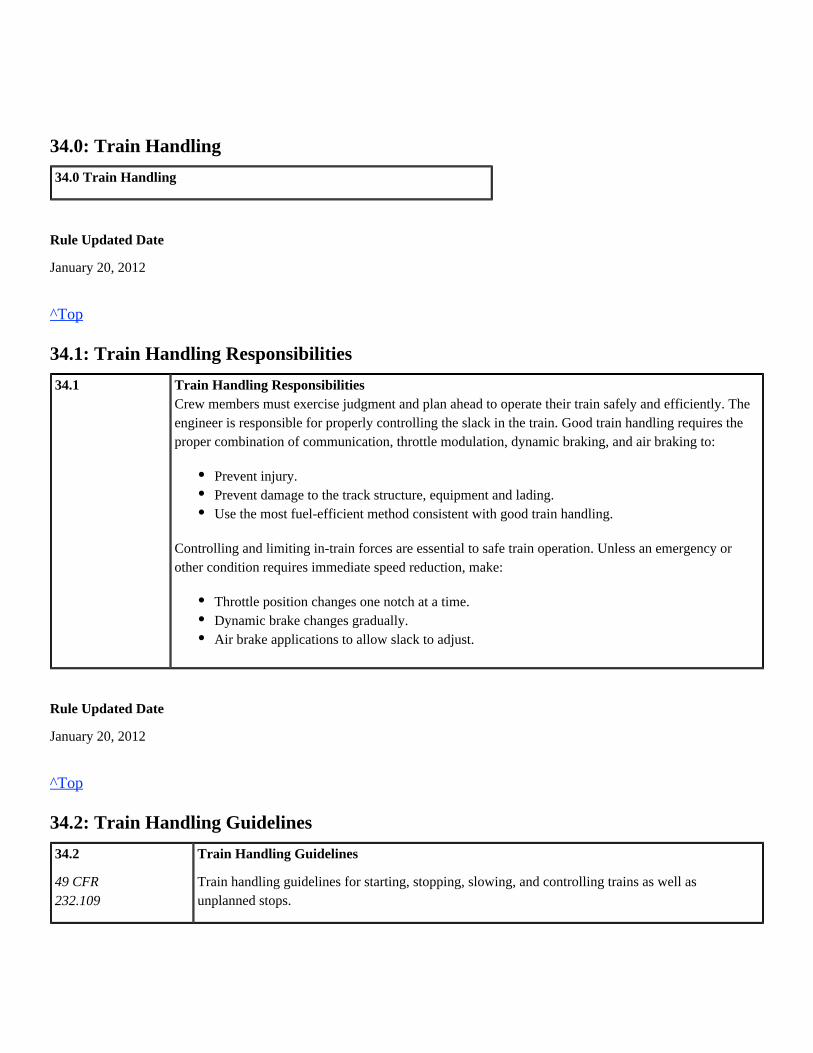
34.0: Train Handling
34.0 Train Handling
Rule Updated Date
January 20, 2012
^Top
34.1: Train Handling Responsibilities
34.1 Train Handling ResponsibilitiesCrew members must exercise judgment and plan ahead to operate their train safely and efficiently. Theengineer is responsible for properly controlling the slack in the train. Good train handling requires theproper combination of communication, throttle modulation, dynamic braking, and air braking to:
Controlling and limiting in-train forces are essential to safe train operation. Unless an emergency orother condition requires immediate speed reduction, make:
Rule Updated Date
January 20, 2012
^Top
34.2: Train Handling Guidelines
34.2
49 CFR232.109
Train Handling Guidelines
Train handling guidelines for starting, stopping, slowing, and controlling trains as well asunplanned stops.
Prevent injury.Prevent damage to the track structure, equipment and lading.Use the most fuel-efficient method consistent with good train handling.
Throttle position changes one notch at a time.Dynamic brake changes gradually.Air brake applications to allow slack to adjust.
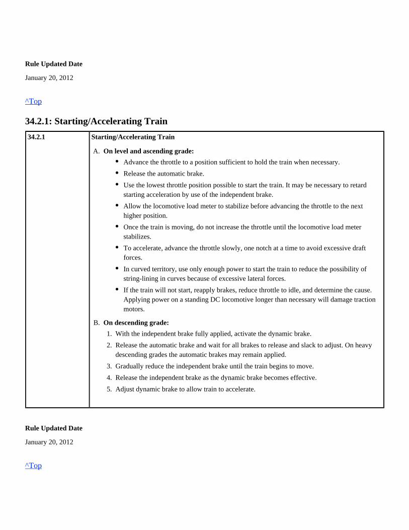
Rule Updated Date
January 20, 2012
^Top
34.2.1: Starting/Accelerating Train
34.2.1 Starting/Accelerating Train
Rule Updated Date
January 20, 2012
^Top
A.
B.
On level and ascending grade:
On descending grade:
Advance the throttle to a position sufficient to hold the train when necessary.
Release the automatic brake.
Use the lowest throttle position possible to start the train. It may be necessary to retardstarting acceleration by use of the independent brake.
Allow the locomotive load meter to stabilize before advancing the throttle to the nexthigher position.
Once the train is moving, do not increase the throttle until the locomotive load meterstabilizes.
To accelerate, advance the throttle slowly, one notch at a time to avoid excessive draftforces.
In curved territory, use only enough power to start the train to reduce the possibility ofstring-lining in curves because of excessive lateral forces.
If the train will not start, reapply brakes, reduce throttle to idle, and determine the cause.Applying power on a standing DC locomotive longer than necessary will damage tractionmotors.
1.
2.
3.
4.
5.
With the independent brake fully applied, activate the dynamic brake.
Release the automatic brake and wait for all brakes to release and slack to adjust. On heavydescending grades the automatic brakes may remain applied.
Gradually reduce the independent brake until the train begins to move.
Release the independent brake as the dynamic brake becomes effective.
Adjust dynamic brake to allow train to accelerate.
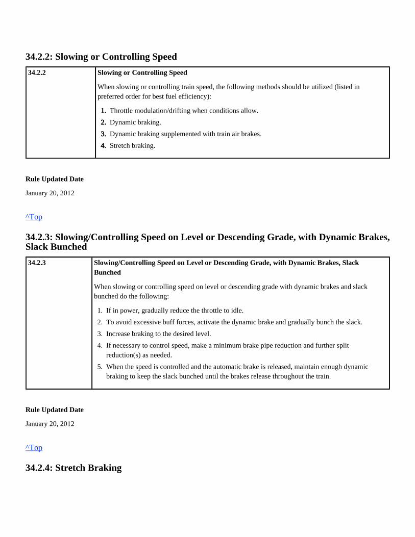
34.2.2: Slowing or Controlling Speed
34.2.2 Slowing or Controlling Speed
When slowing or controlling train speed, the following methods should be utilized (listed inpreferred order for best fuel efficiency):
Rule Updated Date
January 20, 2012
^Top
34.2.3: Slowing/Controlling Speed on Level or Descending Grade, with Dynamic Brakes,Slack Bunched
34.2.3 Slowing/Controlling Speed on Level or Descending Grade, with Dynamic Brakes, SlackBunched
When slowing or controlling speed on level or descending grade with dynamic brakes and slackbunched do the following:
Rule Updated Date
January 20, 2012
^Top
34.2.4: Stretch Braking
1.
2.
3.
4.
Throttle modulation/drifting when conditions allow.
Dynamic braking.
Dynamic braking supplemented with train air brakes.
Stretch braking.
1.
2.
3.
4.
5.
If in power, gradually reduce the throttle to idle.
To avoid excessive buff forces, activate the dynamic brake and gradually bunch the slack.
Increase braking to the desired level.
If necessary to control speed, make a minimum brake pipe reduction and further splitreduction(s) as needed.
When the speed is controlled and the automatic brake is released, maintain enough dynamicbraking to keep the slack bunched until the brakes release throughout the train.

34.2.4
Reference Rule34.5.1
Stretch Braking
Stretch braking is permitted only where more fuel efficient methods will not provide the necessarycontrol of slack and/or train speed. Stretch braking above throttle position 6 is prohibited.
When it becomes necessary to apply the train brakes while in power, ensure that locomotive brakes donot apply and observe the following:
If the entire train is on a descending grade and the train brakes must remain applied, it is permissibleto use limited power to control train speed. Do not exceed throttle position 4, reducing throttle asnecessary to prevent excessive tractive effort.
Rule Updated Date
January 20, 2012
^Top
34.2.5: Ascending Grade
34.2.5 Ascending Grade
When slowing or controlling speed on an ascending grade, do the following:
Rule Updated Date
January 20, 2012
^Top
34.2.6: Cresting Grade
1.
2.
3.
4.
Make the desired throttle adjustment sufficiently in advance to allow the slack to adjust.
After the slack has adjusted, make a minimum brake pipe reduction.
Reduce the throttle when tractive effort increases from the effect of the brake pipe reduction. If aportion of the train is on a grade, the drawbar force may increase rapidly, requiring further throttlereduction(s).
Make additional brake pipe reductions as necessary.
Allow the grade to slow the train.Reduce the throttle one notch at a time to maintain a slack-stretchedcondition.If necessary, make automatic brake pipe reduction(s) to reduce speed.

34.2.6 Cresting Grade
When approaching and cresting a grade:
When operating in heavy or mountain grades, refer to System Special Instructions for additionalrequirements.
Rule Updated Date
January 20, 2012
^Top
34.2.7: Undulating Grade
34.2.7 Undulating Grade
On trains without entrained helper, when slowing or controlling speed on undulating grade:
On trains with entrained or rear helper, do not operate DP trains in synchronous mode throughundulations. Maintain sufficient power on helper(s) to control slack. Site specific train handlinginstructions may apply.
Rule Updated Date
January 20, 2012
^Top
34.2.8: Stopping
34.2.8 Stopping
1.
2.
3.
Reduce the throttle as the lead locomotive crests the grade.
On the lead consist, continue to reduce the throttle and/or apply dynamic brake when necessaryto keep the speed from increasing or make slack adjustments.
When cresting grade with helper(s) on rear or entrained, reduce helper throttle consistent withgood train handling to minimize in train forces.
1.
2.
3.
4.
5.
As the train approaches the undulation, reduce the throttle as necessary to control train speed.
Reduce the throttle further as the head end of the train begins descending.
Just before the head end of the train reaches the ascending grade, increase the throttle.
Continue to increase the throttle as the train ascends the grade.
Reduce the throttle as the rear of the train approaches the ascending grade.

Reference Rule31.534.5.1
A. Level or Descending Grade using Dynamic Brake
When stopping on level or descending grade using dynamic brake:
B. Level or Descending Grade without Dynamic Brake
When stopping on level or descending grade:
C. Level or Ascending Grade, Slack Stretched
When stopping on level or ascending grade:
Rule Updated Date
January 20, 2012
^Top
34.2.9: Unplanned Stops
34.2.9 Unplanned Stops
1.
2.
3.
4.
5.
If in power, gradually reduce the throttle to idle.
Activate the dynamic brake and gradually bunch the slack.
At a sufficient distance from the stop, make a minimum brake pipe reduction.
Make further split reduction(s) as needed.
As dynamic brake retarding force decreases, apply independent brake to avoid slack run-out.
1.
2.
3.
4.
If in power, gradually reduce the throttle to idle and wait for the slack to adjust.
At a sufficient distance from the stop, make a minimum brake pipe reduction.
Make further split reduction(s) as needed.
As the train comes to a stop, use no more independent brake than necessary to maintain a slackbunched condition.
1.
2.
3.
4.
5.
6.
Gradually reduce the throttle.
Maintain sufficient power to keep slack stretched while allowing train to slow.
If necessary, make automatic brake pipe reduction(s) to reduce speed.
When train is approaching the stopping point, make a brake pipe reduction.
As train comes to a stop apply independent brake.
After the independent brake is fully applied, reduce the throttle to idle.
A.Non-EmergencyTo stop in the shortest possible distance without using an emergency brake application, use thefollowing procedure:
1.
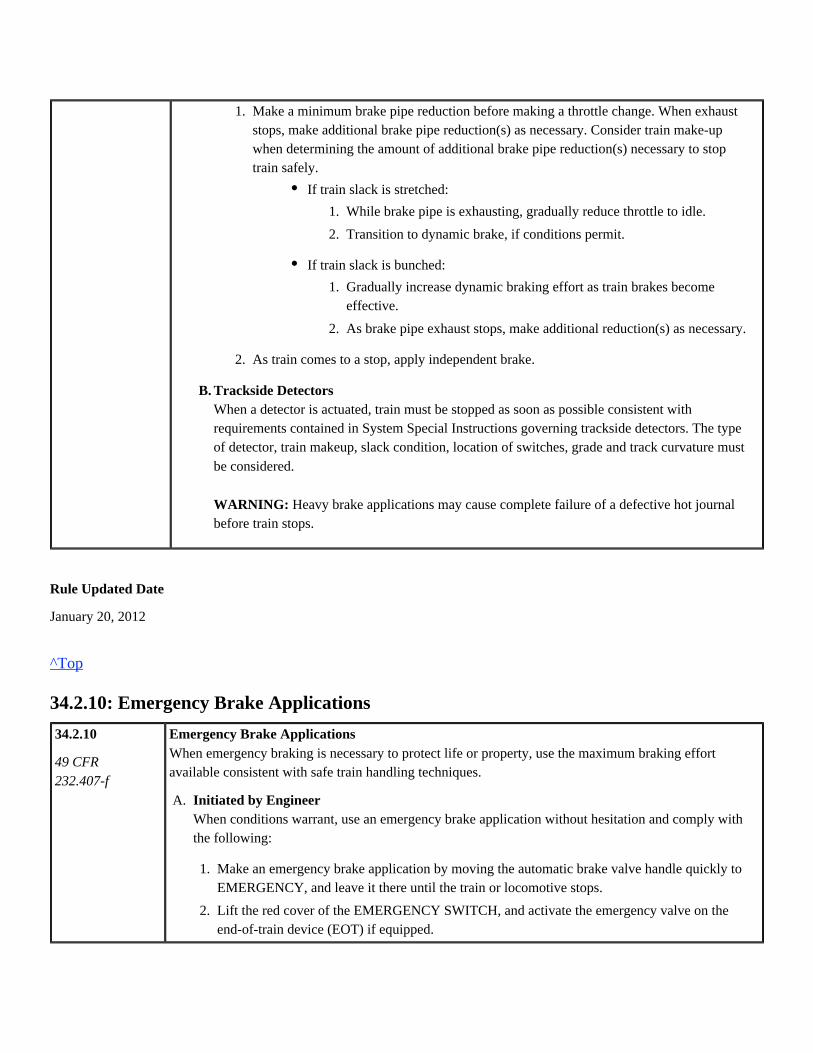
Rule Updated Date
January 20, 2012
^Top
34.2.10: Emergency Brake Applications
34.2.10
49 CFR232.407-f
Emergency Brake ApplicationsWhen emergency braking is necessary to protect life or property, use the maximum braking effortavailable consistent with safe train handling techniques.
B. Trackside DetectorsWhen a detector is actuated, train must be stopped as soon as possible consistent withrequirements contained in System Special Instructions governing trackside detectors. The typeof detector, train makeup, slack condition, location of switches, grade and track curvature mustbe considered.
Heavy brake applications may cause complete failure of a defective hot journalWARNING:before train stops.
1.
2.
Make a minimum brake pipe reduction before making a throttle change. When exhauststops, make additional brake pipe reduction(s) as necessary. Consider train make-upwhen determining the amount of additional brake pipe reduction(s) necessary to stoptrain safely.
As train comes to a stop, apply independent brake.
If train slack is stretched:
If train slack is bunched:
1.
2.
While brake pipe is exhausting, gradually reduce throttle to idle.
Transition to dynamic brake, if conditions permit.
1.
2.
Gradually increase dynamic braking effort as train brakes becomeeffective.
As brake pipe exhaust stops, make additional reduction(s) as necessary.
A. Initiated by EngineerWhen conditions warrant, use an emergency brake application without hesitation and comply withthe following:
1.
2.
3.
Make an emergency brake application by moving the automatic brake valve handle quickly toEMERGENCY, and leave it there until the train or locomotive stops.
Lift the red cover of the EMERGENCY SWITCH, and activate the emergency valve on theend-of-train device (EOT) if equipped.
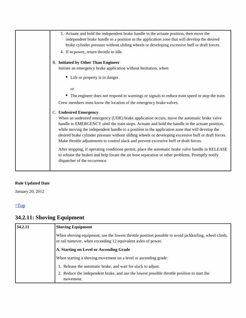
Rule Updated Date
January 20, 2012
^Top
34.2.11: Shoving Equipment
34.2.11 Shoving Equipment
When shoving equipment, use the lowest throttle position possible to avoid jackknifing, wheel climb,or rail turnover, when exceeding 12 equivalent axles of power.
A. Starting on Level or Ascending Grade
When starting a shoving movement on a level or ascending grade:
A.
B.
C.
Initiated by Other Than EngineerInitiate an emergency brake application without hesitation, when:
Crew members must know the location of the emergency brake valves.
Undesired EmergencyWhen an undesired emergency (UDE) brake application occurs, move the automatic brake valvehandle to EMERGENCY until the train stops. Actuate and hold the handle in the actuate position,while moving the independent handle to a position in the application zone that will develop thedesired brake cylinder pressure without sliding wheels or developing excessive buff or draft forces.Make throttle adjustments to control slack and prevent excessive buff or draft forces.
After stopping, if operating conditions permit, place the automatic brake valve handle in RELEASEto release the brakes and help locate the air hose separation or other problems. Promptly notifydispatcher of the occurrence.
3.
4.
Actuate and hold the independent brake handle in the actuate position, then move theindependent brake handle to a position in the application zone that will develop the desiredbrake cylinder pressure without sliding wheels or developing excessive buff or draft forces.
If in power, return throttle to idle.
Life or property is in danger.
or
The engineer does not respond to warnings or signals to reduce train speed or stop the train.
1.
2.
3.
Release the automatic brake, and wait for slack to adjust.
Reduce the independent brake, and use the lowest possible throttle position to start themovement.
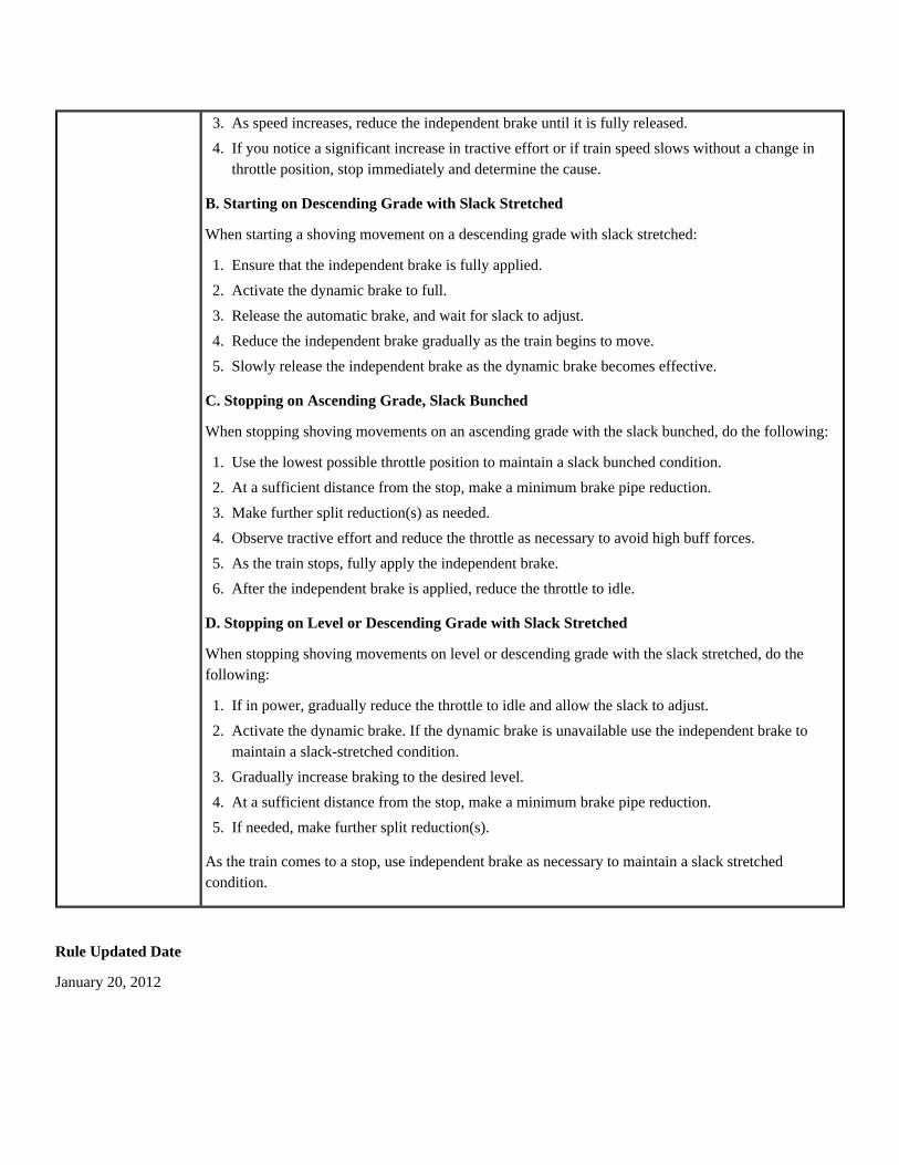
B. Starting on Descending Grade with Slack Stretched
When starting a shoving movement on a descending grade with slack stretched:
C. Stopping on Ascending Grade, Slack Bunched
When stopping shoving movements on an ascending grade with the slack bunched, do the following:
D. Stopping on Level or Descending Grade with Slack Stretched
When stopping shoving movements on level or descending grade with the slack stretched, do thefollowing:
As the train comes to a stop, use independent brake as necessary to maintain a slack stretchedcondition.
Rule Updated Date
January 20, 2012
3.
4.
As speed increases, reduce the independent brake until it is fully released.
If you notice a significant increase in tractive effort or if train speed slows without a change inthrottle position, stop immediately and determine the cause.
1.
2.
3.
4.
5.
Ensure that the independent brake is fully applied.
Activate the dynamic brake to full.
Release the automatic brake, and wait for slack to adjust.
Reduce the independent brake gradually as the train begins to move.
Slowly release the independent brake as the dynamic brake becomes effective.
1.
2.
3.
4.
5.
6.
Use the lowest possible throttle position to maintain a slack bunched condition.
At a sufficient distance from the stop, make a minimum brake pipe reduction.
Make further split reduction(s) as needed.
Observe tractive effort and reduce the throttle as necessary to avoid high buff forces.
As the train stops, fully apply the independent brake.
After the independent brake is applied, reduce the throttle to idle.
1.
2.
3.
4.
5.
If in power, gradually reduce the throttle to idle and allow the slack to adjust.
Activate the dynamic brake. If the dynamic brake is unavailable use the independent brake tomaintain a slack-stretched condition.
Gradually increase braking to the desired level.
At a sufficient distance from the stop, make a minimum brake pipe reduction.
If needed, make further split reduction(s).
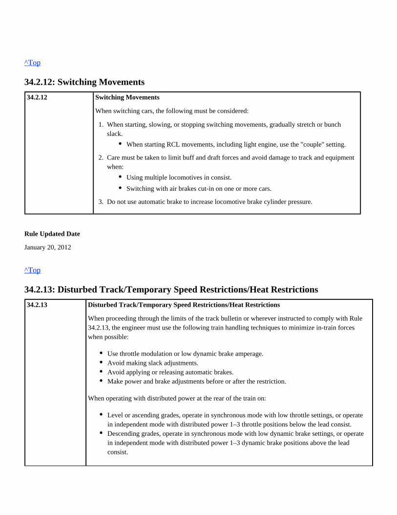
^Top
34.2.12: Switching Movements
34.2.12 Switching Movements
When switching cars, the following must be considered:
Rule Updated Date
January 20, 2012
^Top
34.2.13: Disturbed Track/Temporary Speed Restrictions/Heat Restrictions
34.2.13 Disturbed Track/Temporary Speed Restrictions/Heat Restrictions
When proceeding through the limits of the track bulletin or wherever instructed to comply with Rule34.2.13, the engineer must use the following train handling techniques to minimize in-train forceswhen possible:
When operating with distributed power at the rear of the train on:
1.
2.
3.
When starting, slowing, or stopping switching movements, gradually stretch or bunchslack.
Care must be taken to limit buff and draft forces and avoid damage to track and equipmentwhen:
Do not use automatic brake to increase locomotive brake cylinder pressure.
When starting RCL movements, including light engine, use the "couple" setting.
Using multiple locomotives in consist.
Switching with air brakes cut-in on one or more cars.
Use throttle modulation or low dynamic brake amperage.Avoid making slack adjustments.Avoid applying or releasing automatic brakes.Make power and brake adjustments before or after the restriction.
Level or ascending grades, operate in synchronous mode with low throttle settings, or operatein independent mode with distributed power 1–3 throttle positions below the lead consist.Descending grades, operate in synchronous mode with low dynamic brake settings, or operatein independent mode with distributed power 1–3 dynamic brake positions above the leadconsist.
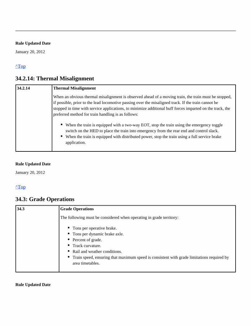
Rule Updated Date
January 20, 2012
^Top
34.2.14: Thermal Misalignment
34.2.14 Thermal Misalignment
When an obvious thermal misalignment is observed ahead of a moving train, the train must be stopped,if possible, prior to the lead locomotive passing over the misaligned track. If the train cannot bestopped in time with service applications, to minimize additional buff forces imparted on the track, thepreferred method for train handling is as follows:
Rule Updated Date
January 20, 2012
^Top
34.3: Grade Operations
34.3 Grade Operations
The following must be considered when operating in grade territory:
Rule Updated Date
When the train is equipped with a two-way EOT, stop the train using the emergency toggleswitch on the HED to place the train into emergency from the rear end and control slack.When the train is equipped with distributed power, stop the train using a full service brakeapplication.
Tons per operative brake.Tons per dynamic brake axle.Percent of grade.Track curvature.Rail and weather conditions.Train speed, ensuring that maximum speed is consistent with grade limitations required byarea timetables.

January 20, 2012
^Top
34.3.1: Balance Braking
34.3.1 Balance Braking
When a constant speed on a grade is required for long distances, use a combination of train air brakesand dynamic brake as follows:
When practicable, use a combination of train air brakes and dynamic brake to control speed whenoperating on descending grades exceeding 1.75%.
Rule Updated Date
January 20, 2012
^Top
34.3.2: Recharging on a Grade
34.3.2 Recharging on a Grade
When necessary to recharge the air brake system while stopped on a grade and the independentbrakes may not hold the train:
Do not apply power to hold a train stationary on a grade unless:
1.
2.
3.
4.
Make a minimum brake pipe reduction when dynamic brake is not sufficient to maintain speed.
Use additional reductions until the desired speed is maintained.
If a greater than 18-psi brake pipe reduction is required to control train speed, stop the train usingemergency application and inspect to determine reason before proceeding.
If an 18-psi reduction is due to Equalizing Reservoir leakage, apply Item 4 below.Exception:
If equalizing reservoir leakage is discovered and speed is decreasing, stop and secure the train, ifnecessary. After placing the automatic brake handle in release, place the brake valve cutoff valve inPASSENGER, if equipped. While operating in PASSENGER, movement of the automatic brakevalve handle toward RELEASE will release the brakes throughout the train.
1.
2.
3.
4.
Apply a sufficient number of hand brakes.
Leave independent brake fully applied, and release the automatic brake.
Recharge the air brake system.
After recharging the system, make a sufficient brake pipe reduction to hold the train whilereleasing the hand brakes.

Rule Updated Date
January 20, 2012
^Top
34.4: Delayed Departure
34.4
Reference Rule33.8.4
Delayed Departure
When stopped and movement is delayed, apply train brakes with at least a 10-psi brake pipe reductionwhen operating conditions permit.
Do not release train brakes until ready to proceed except when:
When trains equipped with an operable EOT are stopped and movement delayed, before moving,verify brake pipe continuity by releasing the air brakes (unless on descending grade and the trainbrakes will remain applied), and observe an increase in pressure on the EOT prior to moving the train.
Distributed power trains must use the automated train check feature to verify brake pipe continuity.
Suspect trainline blockage when a decrease in pressure occurs at the rear of the train that has not beeninitiated by a brake pipe reduction; cause must be determined before departing:
If excessive tractive effort is needed (based on existing conditions) to start the train, inspect the train todetermine the cause.
Rule Updated Date
All locomotive units in the consist are AC locomotives;
orWhen DC locomotive(s) in consist are isolated, remaining AC locomotives may be used tohold train.
Stopped on a grade where it will be necessary to reapply the brakes or will not require thebrakes to be released to start the train.Charging the brake system in heavy or mountain grade territory.Making air test and train movement is initiated within 10 minutes after releasing the trainbrakes.
Inspect train for cause of blockage.A visual observation of a set and release at the rear car is sufficient to determine that noblockage exists.

July 2, 2013
^Top
34.5: Car Air Brakes
34.5 Car Air Brakes
Rule Updated Date
January 20, 2012
^Top
34.5.1: Applying or Reapplying Automatic Brakes
34.5.1 Applying or Reapplying Automatic Brakes
When applying or reapplying automatic brakes, make brake pipe reductions according to theseguidelines:
To prevent the locomotive brakes from applying during an automatic brake application, theindependent brake valve handle must be actuated (bailed) when application is made and held inACTUATE position until exhaust ceases.
Rule Updated Date
January 20, 2012
^Top
34.5.2: Releasing Brakes
34.5.2 Releasing Brakes
Before releasing the brakes, consider the following conditions to avoid damage to equipment,lading, or track:
Make a minimum reduction followed by additional reductions, as necessary.Charged condition of brake pipe must be considered before reapplying air brakes.Make a final reduction when operating conditions permit as train is nearing a stop to prevent arun out of slack.

Running release of the automatic train brakes must not be made when brake application exceeds18-psi.
When operating conditions allow releasing the brakes:
Rule Updated Date
January 20, 2012
^Top
34.5.3: Unintentional Brake Release
34.5.3
49 CFR232.103
Reference Rule32.7.1
Unintentional Brake Release
If an unintentional brake release occurs while the brakes are applied, stop the train and determine thecause before proceeding. Promptly notify dispatcher of the occurrence.
Rule Updated Date
January 20, 2012
^Top
34.5.4: Regulating Valve Braking
34.5.4 Regulating Valve Braking
Use of the regulating valve to control braking is prohibited.
Train speed.Train makeup.Weather conditions.Physical characteristics of territory.Amount of brake pipe reduction.
Make at least a 10-psi total reduction before releasing the brakes unless the brakes will bereapplied shortly.Allow the exhaust at the automatic brake valve to stop before releasing the train brakes.

Rule Updated Date
January 20, 2012
^Top
34.5.5: Retaining Valves
34.5.5 Retaining Valves
Retainers may only be used after consulting with a Manager of Operating Practices for the locationinvolved.
When retaining valves are used:
When retaining valves are not in use, place them in EX (Exhaust).
Rule Updated Date
January 20, 2012
^Top
34.5.6: Use of Automatic Brakes During Cold Weather Conditions
34.5.6
49 CFR232.107
Use of Automatic Brakes During Cold Weather Conditions
During extreme cold weather, (below 10 degrees F) when operating conditions and outstandinginstructions permit, throttle manipulations and dynamic braking must be used in lieu of train air brakeswhenever possible in controlling and stopping freight trains.
Rule Updated Date
January 20, 2012
^Top
34.6: Locomotive Operation
Retaining valves must be set in the "HP" (High Pressure) position on the entire train.Do not exceed 15 MPH.Freight car brake cylinder pressure is not retained until a brake pipe reduction of at least 10-psihas been made and released. Further brake pipe reductions will add to this pressure in thebrake cylinder.
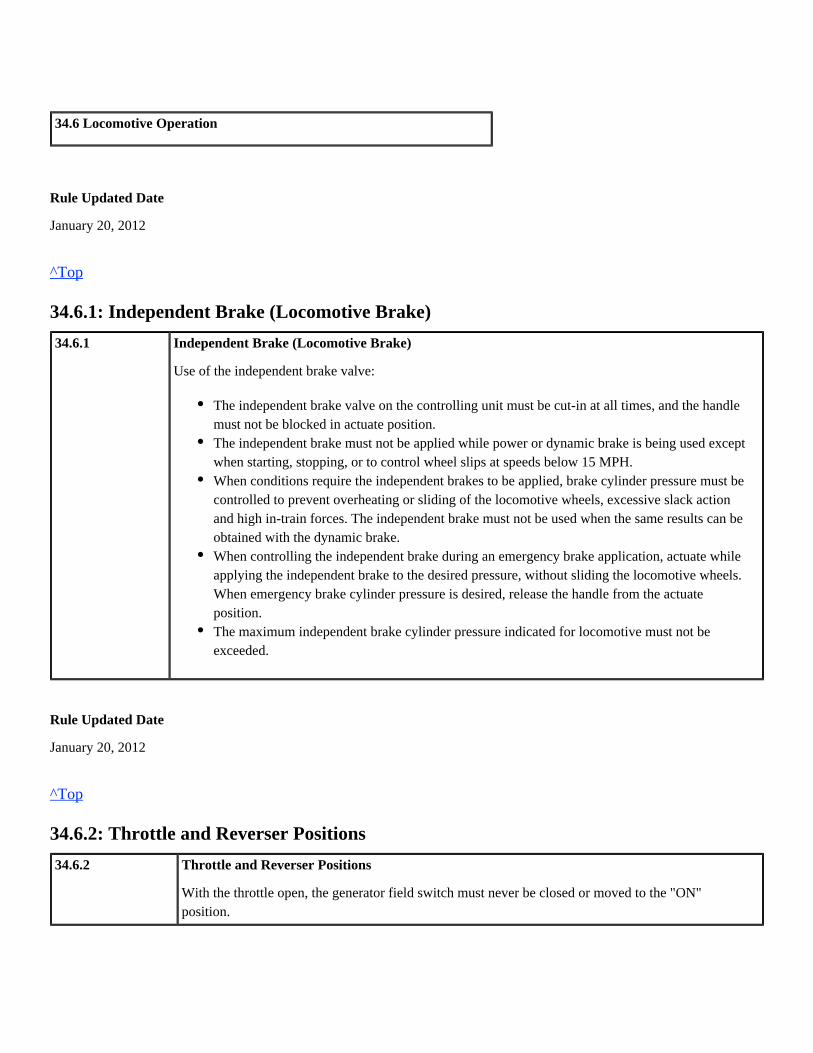
34.6 Locomotive Operation
Rule Updated Date
January 20, 2012
^Top
34.6.1: Independent Brake (Locomotive Brake)
34.6.1 Independent Brake (Locomotive Brake)
Use of the independent brake valve:
Rule Updated Date
January 20, 2012
^Top
34.6.2: Throttle and Reverser Positions
34.6.2 Throttle and Reverser Positions
With the throttle open, the generator field switch must never be closed or moved to the "ON"position.
The independent brake valve on the controlling unit must be cut-in at all times, and the handlemust not be blocked in actuate position.The independent brake must not be applied while power or dynamic brake is being used exceptwhen starting, stopping, or to control wheel slips at speeds below 15 MPH.When conditions require the independent brakes to be applied, brake cylinder pressure must becontrolled to prevent overheating or sliding of the locomotive wheels, excessive slack actionand high in-train forces. The independent brake must not be used when the same results can beobtained with the dynamic brake.When controlling the independent brake during an emergency brake application, actuate whileapplying the independent brake to the desired pressure, without sliding the locomotive wheels.When emergency brake cylinder pressure is desired, release the handle from the actuateposition.The maximum independent brake cylinder pressure indicated for locomotive must not beexceeded.

When moving, reverser handle must not be in a position other than the direction of travel, exceptwhen loading a bulk commodity unit train.
Reverser must be centered when locomotive is stopped. However, reverser may be left in forwardposition when train is stopped in ATC or ACS territory at locations where next signal is not visible.
Rule Updated Date
January 20, 2012
^Top
34.6.3: Dynamic Braking
34.6.3
49 CFR232.109
Dynamic Braking
When using dynamic brake, comply with the following:
Rule Updated Date
January 20, 2012
^Top
34.6.4: Short Time Rating/Minimum Continuous Speed
34.6.4 Short Time Rating/Minimum Continuous Speed
A. Short Time Rating
Short time rating limits for DC locomotives when necessary, are indicated on rating plate located nearor on the load meter; short time rating must not be exceeded.
When lead or remote consist includes a DC locomotive, pause for 10 seconds in idle beforechanging from power to dynamic braking.Do not supplement the dynamic brake with the locomotive brakes unless in the process ofstarting or stopping and speed is below the effective range of the dynamic brakes in yourlocomotive consist.Comply with Equivalent Dynamic Brake Axle limitations by cutting out trailing locomotives(s)or traction motor(s).Approaching and operating through turnouts or disturbed track areas with train's air brakesreleased, limit retarding force to 50% of maximum. Continue to limit the braking effort until atleast half the train has passed the restricted area.
If the locomotive exceeds the short time rating, stop the train and double the train over the grade orallow traction motors time to cool before continuing, unless otherwise instructed.
To provide for sufficient cooling of traction motors, allow the locomotive a minimum of 20 minuteswithout a short time event.
B. Minimum Continuous Speed
Minimum continuous speed is the slowest speed at which a DC locomotive can operate continuouslyin throttle position 8 before overheating. The minimum continuous speed varies and is indicated bythe rating plate on the locomotive.
Rule Updated Date
January 20, 2012
^Top
34.6.5: Penalty Brake Application
34.6.5
49 CFR236.501236.503236.507236.511236.564238.237
Penalty Brake Application
A penalty brake application may be initiated by one of the following safety control devices:
If a safety control device sounds a warning or when a penalty brake application occurs, comply withthe following:
After train stops, reset PCS and release brakes when operating conditions allow.
Rule Updated Date
January 20, 2012
^Top
Alertness Device.Overspeed.Cab Signal.
1.
2.
Move automatic brake valve handle to SUPPRESSION position.
Hold the independent brake handle in the actuate position. Move the independent handle to aposition in the application zone that will develop the desired brake cylinder pressure withoutsliding wheels or developing excessive buff or draft forces.
Union Pacific Rules Air Brake and Train Handling Rules
35.0: Remote Control Operations Chapter 35
35.0: Remote Control Operations
35.0 Remote Control Operations
Rule Updated Date
January 20, 2012
35.0: Remote Control Operations35.1: Reference Materials35.2: Remote Control Area35.3: Equipment35.3.1: Operator Equipment35.3.2: Remote Control Mode35.3.3: Setup and Testing35.3.4: RCL Strobe Lights35.4: Operation35.4.1: Man-down Transmission35.4.2: Remote Control Transmitter Attachment35.4.3: "Pitch and Catch" Operations35.4.4: Operating the Equipment35.4.5: RCL Fails to Respond to Stop Command35.5: Securement35.5.1: Securing Remote Control Equipment35.6: RCL Zone35.6.1: Positive Stop Protection (PSP)35.6.2: Overriding PSP35.6.3: Disabling PSP35.6.4: RCL Zones with Road Crossing Equipped with Cameras35.7: Main Track35.7.1: Remote Control Main Track Operation

^Top
35.1: Reference Materials
35.1 Reference Materials
Employees who set-up or operate remote control equipment must be familiar with the requirementsand instructions for the type of system they will operate. While on duty, remote control operatorsmust have available:
Rule Updated Date
January 20, 2012
^Top
35.2: Remote Control Area
35.2
Reference Rule6.7
Remote Control Area
Rule Updated Date
January 20, 2012
^Top
35.3: Equipment
35.3 Equipment
Remote Control Locomotive Technical Guide.Remote Control Quick Reference Card for the type of system they are operating.
B.
A.Designated Remote Control AreasTimetable Special Instructions will designate areas of remote control operations. Signs advisingthat remote control operations may be in effect will be posted at access locations to remotecontrol areas.
Track Removed from Service or Working Limits EstablishedThe RCO in control of a remote control locomotive must be notified of any track removed fromservice or working limits established for the protection of another craft. The RCO must conducta job/safety briefing with all members of the crew.
Rule Updated Date
January 20, 2012
^Top
35.3.1: Operator Equipment
35.3.1 Operator Equipment
Remote control operators are issued the following equipment:
Remote Control Transmitters are considered safety devices. Employees are prohibited from tamperingwith or disabling any remote control transmitter or safety feature except as provided for in RCO rules.Employees are prohibited from knowingly using a remote control transmitter with a disabled safetydevice.
Rule Updated Date
July 2, 2013
System Special Instructions
Effective Date: April 20, 2012
^Top
35.3.2: Remote Control Mode
35.3.2
Reference Rule5.13
Remote Control Mode
Each locomotive in the remote control consist must have a tag placed in a visible location on thecontrol stand indicating the locomotive is being used in remote control mode. Remove tag when thelocomotive is placed in manual mode.
A Union Pacific approved vest designed to hold the remote control transmitter; RCT must besecurely attached to vest by using all 4 "D" rings. The RCL vest must be worn as the outer mostgarment.At least one approved hands-free light. In case of failure, a lantern may be used in place of thehands-free light.A hand-held radio equipped with a wired microphone. Radio must be holstered or affixed to abelt.
Rule Updated Date
January 20, 2012
^Top
35.3.3: Setup and Testing
35.3.3 Setup and Testing
Prior to operating a remote control system, the RCO must ensure the equipment is properly setupand tested in accordance with prescribed procedures.
When two remote control transmitters are utilized, the conductor/foreman must always link as"Operator A" and the second operator as "Operator B."
Rule Updated Date
January 20, 2012
^Top
35.3.4: RCL Strobe Lights
35.3.4 RCL Strobe LightsStrobe lights must be on during Remote Control Operations.
If both RCL strobe lights fail during a tour of duty, the locomotive may be used until end of the shiftor the next daily inspection, whichever occurs first. Strobe lights must be repaired before locomotiveis again used in remote service.
Rule Updated Date
January 20, 2012
^Top
35.4: Operation
35.4 Operation
Rule Updated Date
January 20, 2012

^Top
35.4.1: Man-down Transmission
35.4.1 Man-down Transmission
The designated supervisor must monitor radio communications for man-down messages transmitted byremote control locomotive radios.
If a man-down message is transmitted, the supervisor will immediately attempt to contact the crewwhose RCL-equipped locomotive has transmitted the man-down message. If unable to determine thereason for the man-down message, 911 must be called immediately.
At locations without supervisors, employees hearing a man-down message must determine the reasonfor the message and take appropriate action. This does not relieve nor prevent any employee fromdeclaring an emergency and contacting 911 when such a message is heard.
Employees must follow local emergency procedures when man-down message is transmitted.
Rule Updated Date
January 20, 2012
^Top
35.4.2: Remote Control Transmitter Attachment
35.4.2 Remote Control Transmitter Attachment
When a linked RCT is attached to a vest, lean forward with RCT hanging freely until tilt warning isactivated, then upright the RCT before timing out.
When transferring linked RCT's to another crew, RCT "A" must be transferred to theprimary/conductor/foreman operator and RCT "B" to the secondary/helper/switchman operator.
Rule Updated Date
January 20, 2012
^Top
35.4.3: "Pitch and Catch" Operations
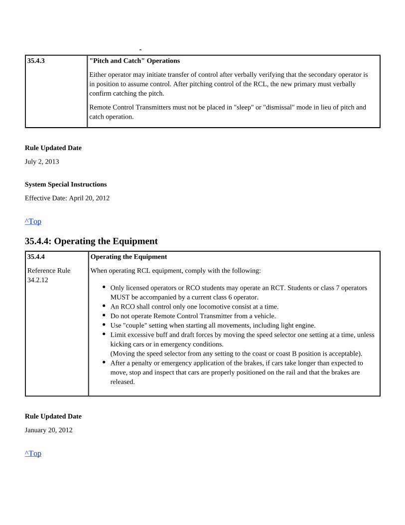
35.4.3: "Pitch and Catch" Operations
35.4.3 "Pitch and Catch" Operations
Either operator may initiate transfer of control after verbally verifying that the secondary operator isin position to assume control. After pitching control of the RCL, the new primary must verballyconfirm catching the pitch.
Remote Control Transmitters must not be placed in "sleep" or "dismissal" mode in lieu of pitch andcatch operation.
Rule Updated Date
July 2, 2013
System Special Instructions
Effective Date: April 20, 2012
^Top
35.4.4: Operating the Equipment
35.4.4
Reference Rule34.2.12
Operating the Equipment
When operating RCL equipment, comply with the following:
Rule Updated Date
January 20, 2012
^Top
Only licensed operators or RCO students may operate an RCT. Students or class 7 operatorsMUST be accompanied by a current class 6 operator.An RCO shall control only one locomotive consist at a time.Do not operate Remote Control Transmitter from a vehicle.Use "couple" setting when starting all movements, including light engine.Limit excessive buff and draft forces by moving the speed selector one setting at a time, unlesskicking cars or in emergency conditions.(Moving the speed selector from any setting to the coast or coast B position is acceptable).After a penalty or emergency application of the brakes, if cars take longer than expected tomove, stop and inspect that cars are properly positioned on the rail and that the brakes arereleased.

35.4.5: RCL Fails to Respond to Stop Command
35.4.5 RCL Fails to Respond to Stop Command
If the locomotive fails to respond properly to a stop command from the remote control transmitter, theRCO must:
The RCO must then secure the equipment including the transmitter. The RCO must contact themanager on duty and not attempt to operate the locomotive until authorized by a DSRCO orMechanical Department employee.
Rule Updated Date
January 20, 2012
^Top
35.5: Securement
35.5 Securement
Rule Updated Date
January 20, 2012
^Top
35.5.1: Securing Remote Control Equipment
35.5.1
Reference Rule31.8.7.132.2.1
Securing Remote Control EquipmentRemote control locomotives and remote control transmitter(s) must not be left unattended unlesssecured. At the end of a shift, RCT's must be unlinked and stored in a locked cabinet with batteryplaced in charger unless transferred directly to another RCL job.
1.
2.
Place RCT in emergency.
Immediately power off the transmitter or remove RCT battery.
A.Short Term Securement (90 minutes or less)The RCO will secure the remote control locomotive as follows:
1.
2.
3.
4.
Isolate and apply hand brakes on all locomotives.
Perform securement check before turning off the remote control transmitter.
RCO must maintain possession of the transmitter(s).

Rule Updated Date
July 2, 2013
^Top
35.6: RCL Zone
35.6 RCL Zone
Rule Updated Date
January 20, 2012
^Top
35.6.1: Positive Stop Protection (PSP)
35.6.1
Reference Rule6.7
Positive Stop Protection (PSP)
The RCO must verify that the PSP is operational on initial movement into an activated RCL zone.Receiving a remote control transmitter message when entering the limits verifies that PSP isfunctioning properly.
B. Long Term Securement (more than 90 minutes) or Ending Tour of DutyThe RCO will secure the remote control locomotive as follows:
4. When equipment will be left for more than 15 minutes, comply with locomotiveshutdown requirements.
Leave the Control and RCL circuit breakers ON and main battery switchclosed to maintain the link.
If linked to a control car or slug, the battery switch on the conventional unitmust be closed to maintain the power supply.
1.
2.
3.
4.
5.
6.
7.
Isolate and secure consist.
Leave the RCL breaker on.
Place RCL in MANUAL mode as outlined in the RCL Technical Guide.
Remove remote control warning sign(s).
Ensure that one locomotive is set-up for lead unit operation.
Perform locomotive securement test.
Shut down the locomotive(s) as required.

Rule Updated Date
January 20, 2012
^Top
35.6.2: Overriding PSP
35.6.2 Overriding PSP
Use procedures in the RCL Technical Guide to override and reactivate PSP for each RCL system.
When PSP is overridden, point protection must be provided. PSP must be seen to be functioning asintended before it can be depended on to stop the locomotive again.
Rule Updated Date
January 20, 2012
^Top
35.6.3: Disabling PSP
35.6.3 Disabling PSP
PSP may only be disabled in the event of GPS or PSPfailure.
Rule Updated Date
January 20, 2012
^Top
35.6.4: RCL Zones with Road Crossing Equipped with Cameras
35.6.4
Reference Rule6.32
RCL Zones with Road Crossing Equipped with Cameras
When using cameras for movements over road crossings, movement must not exceed 4 MPH untilcrossing is occupied. An employee must observe the monitors to ensure that automatic crossingwarning devices activate and remain active until the crossing is occupied.
If cameras are not used or are inoperative, employee must provide warning at the crossing.

Rule Updated Date
January 20, 2012
^Top
35.7: Main Track
35.7 Main Track
Rule Updated Date
January 20, 2012
^Top
35.7.1: Remote Control Main Track Operation
35.7.1 Remote Control Main Track Operation
Main track movements include train movements, yard transfers, etc.; it does not include doubling atrain together, using the main track for head room or adding cars to a train on the main track, i.e.,switching movements.
When main track movements exceed 1 mile, do not exceed the following limits:
Rule Updated Date
January 20, 2012
^Top
12 equivalent powered axles (EPA).60 cars/platforms/wells.4,000 tons.

Union Pacific Rules Air Brake and Train Handling Rules
36.0: Positive Train Control Chapter 36
36.0: Reserved for PTC Operations
Reserved for PTC Operations
Rule Updated Date
January 20, 2012
^Top
36.0: Reserved for PTC Operations

Union Pacific Rules Air Brake and Train Handling Rules
37.0: Reserved for Future Use - Chapter 37
37.0: Reserved for Future Use
Reserved for Future Use
Rule Updated Date
January 20, 2012
^Top
37.0: Reserved for Future Use

Union Pacific Rules Air Brake and Train Handling Rules
38.0: Commuter/Business Train Operations - Chapter 38
38.0: Commuter/Business Train Air Brake Rules
38.0 Commuter/Business Train Air Brake Rules
Rule Updated Date
January 20, 2012
^Top
38.1: Passenger Equipment Inspections
38.1 Passenger Equipment Inspections
Inspect and test passenger equipment according to Federal Railroad Administration (FRA)regulations contained within these rules.
38.0: Commuter/Business Train Air Brake Rules38.1: Passenger Equipment Inspections38.1.1: Inspections and Brake Tests38.1.2: Class I Brake Test38.1.3: Class IA Brake Test38.1.4: Class II Brake Test38.1.5: Running Brake Tests38.2: Commuter Operation Air Brake Test and Inspections38.2.1: Air Brake Test Requirements38.2.2: Procedure for a Running Brake Test38.2.3: Changing Operating Ends on Trains Equipped with Cab Cars38.2.4: Parking Brake and Hand Brakes38.2.5: Using Blended Braking38.3: Operative Brakes38.3.1: Defective Train Brakes38.3.2: Operative Brake Conditions38.3.3: Operable Brakes38.3.4: Defective Brake Chart

Rule Updated Date
January 20, 2012
^Top
38.1.1: Inspections and Brake Tests
38.1.1 Inspections and Brake Tests
Inspections and brake tests must be performed on commuter/business passenger trains by a QualifiedMaintenance Person or by a Qualified Person.
Rule Updated Date
January 20, 2012
^Top
38.1.2: Class I Brake Test
38.1.2
49 CFR238.313
Reference Rule30.2.4
Class I Brake Test
When to Perform a Class I Test
A Class I brake test must be conducted on commuter/business passenger trains:
Notification of Completed Test
Only a Qualified Maintenance Person may perform a Class I brake test.Either a Qualified Maintenance Person or a Qualified Person may perform a Class IA or aClass II brake test.
Once each calendar day that the train is placed or continues in service.On each car added to a train at the time it is added to a train, unless documentation is providedto the train crew that a Class I brake test was performed on the car on that calendar day, and thecar has not been disconnected from a source of compressed air for more than four hours prior tobeing added to the train. However, a Class IA test may be conducted on the car in lieu of theabove.The test may be performed in conjunction with the calendar day exterior mechanical inspection.Except as provided in these rules, a train may not be used in passenger service or hauled from alocation where a Class I brake test has been performed, or was required to have been performed,with less than 100% operative brakes.

A Qualified Maintenance Person that performs a Class I brake test on a train may notify the crew of theClass I brake test or place a written statement (see Appendix A) in the rear cab car's B-1 locker until thenext Class I brake test is performed. The statement shall contain:
Rule Updated Date
January 20, 2012
^Top
38.1.3: Class IA Brake Test
38.1.3
49 CFR238.315
Reference Rule38.2.1
Class IA Brake Test
A. When to Perform a Class IA Brake Test
Either a Class I or Class IA brake test shall be performed prior to the first calendar day departure ofeach commuter/business passenger train, unless all of the following conditions are satisfied:
Either a Class I or Class IA brake test shall be performed prior to placing a commuter/businesspassenger train in service that has been off air for more than four hours.
Rule Updated Date
January 20, 2012
^Top
The date and the time the Class I brake test took place.The location where the test was performed.The identification number of the controlling locomotive of the train.The total number of cars inspected during the Class I brake test.The signature or employee ID of the inspector.
A Class I brake test was performed within the previous 12 hours.The train has not been used in commuter/business service since the performance of the Class Ibrake test.The train has not been off a compressed air source for more than four hours since theperformance of the Class I brake test.A commuter/business train that provides continuing late night service that began prior tomidnight may complete its daily operating cycle without performing another Class I or Class IAbrake test. A Class I or Class IA test shall be performed on such a train before it starts a newdaily operating cycle.

38.1.4: Class II Brake Test
38.1.4
49 CFR238.317
Reference Rule38.2.1
Class II Brake Test
A. When to Perform a Class II Brake Test
A Class II brake test shall be performed on a commuter/business passenger train when any of thefollowing events occur:
Rule Updated Date
January 20, 2012
^Top
38.1.5: Running Brake Tests
38.1.5
49 CFR238.319
Running Brake Tests
When to Perform Test
As soon as conditions safely permit, a running brake test shall be performed on a commuter/businesstrain after the train has departed a point where:
Rule Updated Date
Whenever the control stand used to control the train is changed or any time the controlling endis cut-out and then cut back in.Prior to the first calendar day departure where a Class I brake test remains valid.When cars that have received a Class I brake test within the previous calendar day and havenot been disconnected from a source of compressed air for more than four hours are added tothe train.When cars or equipment are removed from the train.Before a train enters the main track when a crew first takes charge of the train, except forface-to-face relief.
A Class I, Class IA, or Class II brake test was performed.Any angle cocks or cutout cocks have been closed.A train has struck debris on the track.A train reaches a point designated by the timetable or special instructions.Locomotive or operating ends have been changed.Crew changes are located.Movement is being controlled with a back-up hose or valve. The back-up hose or valve mustbe used to conduct the test.

January 20, 2012
^Top
38.2: Commuter Operation Air Brake Test and Inspections
38.2 Commuter Operation Air Brake Test and Inspections
Rule Updated Date
January 20, 2012
^Top
38.2.1: Air Brake Test RequirementsPassenger Air Brake Tests
Type ofTest
PerformWalkingInspection
Brakepipepressureset at90-psi .4
Leakagetest asrequiredper rule30.11.2Part B.Leakagemust notexceed 5lbs/min.
20-psibrakepipereduction
Check that brake shoesare properly fastenedand seated against thewheel. Brake riggingdoes not bind or foul.Angle cocks are properlypositioned.
When notified, releasethe brakes. Properrelease of the brakes canbe determined byobservation of theclearance between thebrake shoe and thewheel.
Verifybrakepipepressurechanges atrearof train byobservinggaugeduringapplicationandrelease ofrear car 5
Verify thecommunicatingsignal system istested andknown tobe operating asintended. Anyone ofthe followingmeetthisrequirement:two-way radiosystem,electricalline (buzzer) orPAsystem.
Verify theemergencybrakeapplicationanddeadmanpedal orotheremergencycontroldevicesfunction asintended.
Allcars
Car(s) pickedup
Allcars
Car(s) pickedup
Class I1 X X X X X X X X X X
ClassIA2
X X X X X X X X X
Class II2
X X X X
RunningTest
Perform the test as follows:
If the air brakes do not operate properly, stop the train and contact Commuter Control or the Train Dispatcher for instructions. Be governed by the instructions in.Defective Train Brake procedures (Rule 38.4.3)
Cars must be inspected by a Qualified Maintenance Inspector.1
Cars must be inspected by a Qualified Maintenance Inspector or Qualified Person.2
Cars added enroute must be tested as outlined above. Cars are set out—determine that brake pipe pressure at the rear car has3
1.
2.
3.
4.
Leave power in low throttle position.
If operating from the locomotive, actuate the independent brake.
Apply the train air brakes with enough force to determine the brakes are operating properly.
If the train brakes are operating properly, release the brakes and proceed.
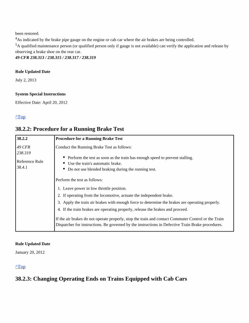
been restored.
As indicated by the brake pipe gauge on the engine or cab car where the air brakes are being controlled.4
A qualified maintenance person (or qualified person only if gauge is not available) can verify the application and release by5
observing a brake shoe on the rear car.49 CFR 238.313 / 238.315 / 238.317 / 238.319
Rule Updated Date
July 2, 2013
System Special Instructions
Effective Date: April 20, 2012
^Top
38.2.2: Procedure for a Running Brake Test
38.2.2
49 CFR238.319
Reference Rule38.4.1
Procedure for a Running Brake Test
Conduct the Running Brake Test as follows:
Perform the test as follows:
If the air brakes do not operate properly, stop the train and contact Commuter Control or the TrainDispatcher for instructions. Be governed by the instructions in Defective Train Brake procedures.
Rule Updated Date
January 20, 2012
^Top
38.2.3: Changing Operating Ends on Trains Equipped with Cab Cars
Perform the test as soon as the train has enough speed to prevent stalling.Use the train's automatic brake.Do not use blended braking during the running test.
1.
2.
3.
4.
Leave power in low throttle position.
If operating from the locomotive, actuate the independent brake.
Apply the train air brakes with enough force to determine the brakes are operating properly.
If the train brakes are operating properly, release the brakes and proceed.
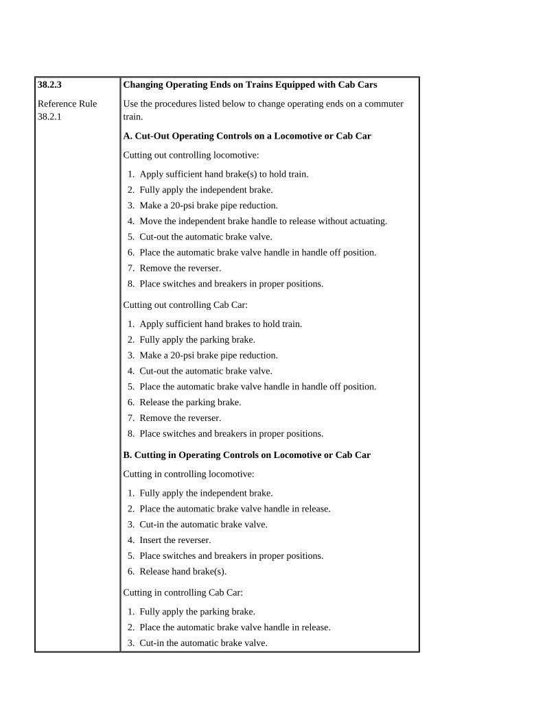
38.2.3
Reference Rule38.2.1
Changing Operating Ends on Trains Equipped with Cab Cars
Use the procedures listed below to change operating ends on a commutertrain.
A. Cut-Out Operating Controls on a Locomotive or Cab Car
Cutting out controlling locomotive:
Cutting out controlling Cab Car:
B. Cutting in Operating Controls on Locomotive or Cab Car
Cutting in controlling locomotive:
Cutting in controlling Cab Car:
1.
2.
3.
4.
5.
6.
7.
8.
Apply sufficient hand brake(s) to hold train.
Fully apply the independent brake.
Make a 20-psi brake pipe reduction.
Move the independent brake handle to release without actuating.
Cut-out the automatic brake valve.
Place the automatic brake valve handle in handle off position.
Remove the reverser.
Place switches and breakers in proper positions.
1.
2.
3.
4.
5.
6.
7.
8.
Apply sufficient hand brakes to hold train.
Fully apply the parking brake.
Make a 20-psi brake pipe reduction.
Cut-out the automatic brake valve.
Place the automatic brake valve handle in handle off position.
Release the parking brake.
Remove the reverser.
Place switches and breakers in proper positions.
1.
2.
3.
4.
5.
6.
Fully apply the independent brake.
Place the automatic brake valve handle in release.
Cut-in the automatic brake valve.
Insert the reverser.
Place switches and breakers in proper positions.
Release hand brake(s).
1.
2.
3.
4.
Fully apply the parking brake.
Place the automatic brake valve handle in release.
Cut-in the automatic brake valve.

Rule Updated Date
October 26, 2012
^Top
38.2.4: Parking Brake and Hand Brakes
38.2.4 Parking Brake and Hand Brakes
A. Parking Brake
Cab cars are equipped with a parking brake that has two positions:
When the cab car automatic brake is cut-out, the parking brake is inoperative.
Except in an emergency, do not use the parking brake to slow or stop a train. It must be determinedthat the parking brake is released on the cab car prior to initiating movement.
B. Hand Brakes
It must be determined that hand brakes are released on all cars and locomotives prior to initiatingmovement.
Rule Updated Date
January 20, 2012
^Top
38.2.5: Using Blended Braking
38.2.5
49 CFR238.231
Using Blended Braking
Locomotives may be equipped with a combination air brake and dynamic brake system called blendedbraking. If so equipped, blended braking is the preferred method of slowing and stopping the train. Theamount of blended braking varies with speed and amount of air brake application.
4.
5.
6.
Insert the reverser.
Place switches and breakers in proper positions.
Release hand brake(s).
Released.Fully applied.

Blended braking will occur with an automatic brake application if:
Rule Updated Date
January 20, 2012
^Top
38.3: Operative Brakes
38.3 Operative Brakes
Rule Updated Date
January 20, 2012
^Top
38.3.1: Defective Train Brakes
38.3.1
49 CFR238.215
Defective Train Brakes
Commuter/business equipment that develop inoperative brakes enroute may be moved in compliancewith when a tag or card is placed on both sides of the defective passenger equipment.Rule 38.3.4
The information on the tag or card must include:
Rule Updated Date
January 20, 2012
Blended brake cut-out switch is ON.Throttle is in IDLE.Independent brake valve handle on the locomotive is released and not actuated.
Equipment number.Railroad.Location.Date.Nature of defect.Destination for repair.Signature and title of person reporting the defect.
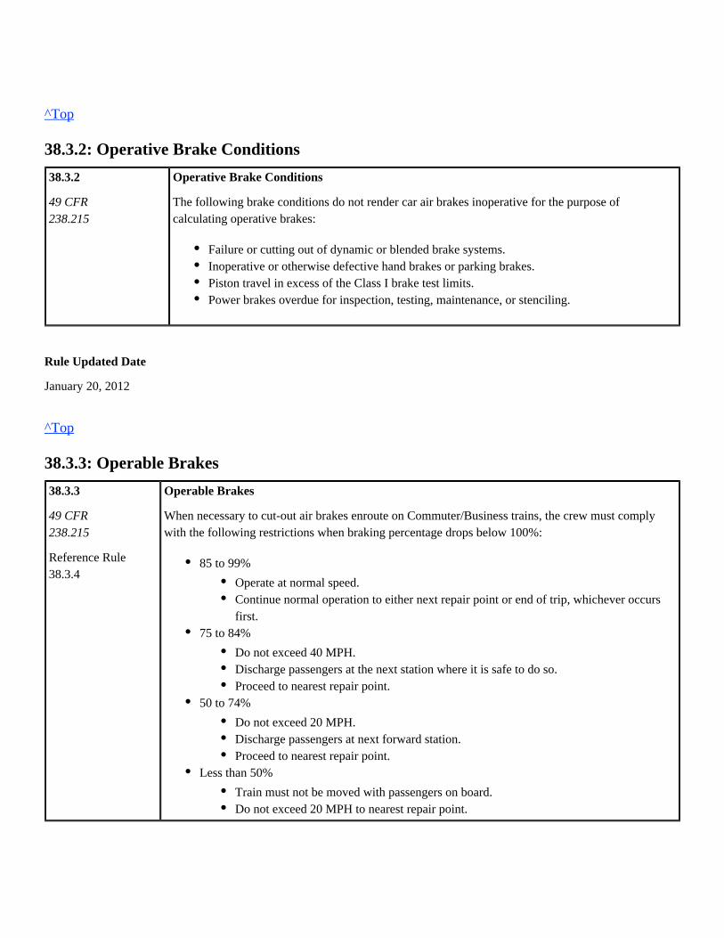
^Top
38.3.2: Operative Brake Conditions
38.3.2
49 CFR238.215
Operative Brake Conditions
The following brake conditions do not render car air brakes inoperative for the purpose ofcalculating operative brakes:
Rule Updated Date
January 20, 2012
^Top
38.3.3: Operable Brakes
38.3.3
49 CFR238.215
Reference Rule38.3.4
Operable Brakes
When necessary to cut-out air brakes enroute on Commuter/Business trains, the crew must complywith the following restrictions when braking percentage drops below 100%:
Failure or cutting out of dynamic or blended brake systems.Inoperative or otherwise defective hand brakes or parking brakes.Piston travel in excess of the Class I brake test limits.Power brakes overdue for inspection, testing, maintenance, or stenciling.
85 to 99%
75 to 84%
50 to 74%
Less than 50%
Operate at normal speed.Continue normal operation to either next repair point or end of trip, whichever occursfirst.
Do not exceed 40 MPH.Discharge passengers at the next station where it is safe to do so.Proceed to nearest repair point.
Do not exceed 20 MPH.Discharge passengers at next forward station.Proceed to nearest repair point.
Train must not be moved with passengers on board.Do not exceed 20 MPH to nearest repair point.
To calculate operable brake percentage:
The crew is required to cut-out one truck on a car. Use the following formula to calculate the newbraking percentage:
Locomotive trucks + car trucks 2 + 10 = 12 Total trucks
Subtract BO truck(s) = 1 from total trucks
12 – 1 = 11 Total operative trucks
Divide number of operative trucks by the total number of trucks in the train, then multiply by 100.
Operative trucks 11/ total trucks 12 = .916 X 100 = 91.6%
When Front or Rear Unit are Inoperative
If power brakes on the front or rear unit are inoperative, the following shall apply:
Rule Updated Date
January 20, 2012
^Top
38.3.4: Defective Brake Chart
1.
2.
3.
Determine total number of trucks in the train.
Subtract the number of cutout trucks from the total number of trucks in the train.
Divide the number of operative trucks by the total number of trucks in the train then multiply itby 100.
Train Information – 1 Locomotive / 2 trucks and 5 Cars / 10 trucksExample:
Count each cut-out locomotive truck as 2 cut-out trucks.
If the hand brake is located inside the interior of the equipment:
If the hand brake is located outside the interior of the equipment or is inaccessible to aQualified Person:
Notify the Mechanical Department of the failure.
A Qualified Person must be stationed at the hand brake on the unit.The car must be locked out and empty, except for the railroad employee manning thehand brake.Comply with applicable speed restriction.
The car must be locked out and empty.The train may be moved at Restricted Speed to the first location where car must beremoved or repositioned in the train.

38.3.4 Defective Brake Chart
Rule Updated Date
January 20, 2012
^Top
Union Pacific Rules Air Brake and Train Handling Rules
39.0: Equipment Charts/Diagrams - Brakes - Chapter 39
39.0: Freight Car and Locomotive Components
39.0 Freight Car and Locomotive Components
Rule Updated Date
January 20, 2012
39.0: Freight Car and Locomotive Components39.1: Freight Car Components39.1.1: Freight Car End and Platform Identification39.1.2: Wheel and Journal Identification on Cars39.1.3: High Strength Couplers39.1.3.1: High Strength Coupler Identification39.1.4: Freight Car A-1 Reduction Relay Valve39.1.5: Freight Car Automatic Vent Valve39.1.6: Retaining Valves39.1.7: Charging Time Chart39.2: Locomotive Components39.2.1: Automatic Brake Valves39.2.2: Automatic Brake Valve Cutout Valve39.2.3: Independent Brake Valves39.2.4: MU-2A/Double-Ported Cutout Cock39.2.5: Electro pneumatic Automatic and Independent Brake Valves39.2.6: Locomotive Electronic Air Brake Computer Resets Resetting CCB Faults39.2.7: Air Flow Meter39.2.8: Overspeed Control39.3: Charts and Diagrams39.3.1: Car Chart Components39.3.2: Terminology for Articulated Car Identification Diagram39.3.3: Coupler Diagram39.3.4: Locomotive Axle, Journal, and Wheel Identification Diagram39.3.5: Locomotive Air Brake Equipment
^Top
39.1: Freight Car Components
39.1 Freight Car Components
Rule Updated Date
January 20, 2012
^Top
39.1.1: Freight Car End and Platform Identification
39.1.1 Freight Car End and Platform Identification
Identify car ends as follows:
Rule Updated Date
January 20, 2012
^Top
39.1.2: Wheel and Journal Identification on Cars
39.1.2 Wheel and Journal Identification on Cars
To determine the correct wheel numbers on cars:
On cars with one hand brake, the "B" end of the car is the end with the hand brake. The otherend is the "A" end.On cars with more than one hand brake, the letters "A" and "B" are stenciled on theappropriate ends of the car.On cars with more than one platform, each section if stenciled.Example: A five-platform articulated spine car is designated with an "A" platform on one endand the adjacent platform is designated as "E" then "D", then "C" and then "B" on the oppositeend.
1.
2.
Face the "B" end of the car.
From the "B" end of the car, identify the designation of wheels, journals, and axles asfollows:
Rule Updated Date
January 20, 2012
^Top
39.1.3: High Strength Couplers
39.1.3 High Strength CouplersEach car is to be considered equipped with a standard type coupler unless it is known the car isequipped with high strength couplers.
Coal cars, covered hopper cars and cars designed to carry TOFC vans and/or containers are equippedwith high strength couplers. If it is not known that a car is equipped with high strength couplers, it canbe determined by looking at the coupler casting identification located on top of the coupler.
A high strength coupler will have the letter "E" or "EX" as the last character(s) of identification.Examples of high strength coupler identifications are E60HTE, SBE60CE, E60DE, EF512WEX.
Rule Updated Date
January 20, 2012
^Top
39.1.3.1: High Strength Coupler Identification
39.1.3.1 High Strength Coupler Identification
If it is not known that a car is equipped with high strength couplers, it can be determined by looking atthe coupler casting identification located on top of the coupler. A high strength coupler will have theletter "E" or "EX" as the last character of identification. Examples of high strength coupleridentifications are E60HTE, SBE60CE, SBE60DE, EF512WEX.
2.
Axles are designated from the "B" end of the car with "1" for the axle closest to the"B" end.
Wheels and journals are designated left or right as viewed from the "B" end.
Specific wheels are identified using the axle and wheel designation.

Rule Updated Date
July 2, 2013
^Top
39.1.4: Freight Car A-1 Reduction Relay Valve
39.1.4 Freight Car A-1 Reduction Relay Valve
Some long cars have an A-1 reduction relay valve that helps transmit a service or emergency brakepipe reduction by compensating for the added brake pipe length of the car.
The relay valve functions as follows:
The following freight cars are equipped with the relay valve:
Cars with ABDW control valves having between 75 and 100 feet of brake pipe have a No. 8Note:vent valve added.
Service brake reductions are assisted through the B-1 quick service portion.Emergency brake pipe reductions are transmitted by the No. 8 vent valve portion. If the No. 8vent valve fails to reset after an emergency brake application, causing a continuous blow at theexhaust port, plug the valve by removing the vent protector and screwing in the threaded plug.
Cars with AB or ABD control valves and more than 75 feet of brake pipe between hosecouplings.Cars with ABDW control valves and more than 100 feet of brake pipe between hose couplings.

Rule Updated Date
January 20, 2012
^Top
39.1.5: Freight Car Automatic Vent Valve
39.1.5 Freight Car Automatic Vent Valve
Some multi-platform cars are equipped with what is known as an automatic vent valve (AVV), whichis an emergency portion of a control valve. This valve is used only to propagate an emergency brakeapplication through the brake pipe. Should an AVV become defective, the cutout cock is used to cut itout.
Rule Updated Date
January 20, 2012
^Top
39.1.6: Retaining Valves
39.1.6 Retaining Valves
The retaining valve on each car controls the brake cylinder pressure exhaust. All freight cars haveretaining valves located at the "B" end of the car or at the side near the control valve. The retainingvalve can be positioned to function as follows during a brake release:
A. Three-Position Retaining Valve
The three-position retaining valve includes these positions.
B. Four-Position Retaining Valve
The four-position retaining valve includes the positions listed above and one additional position:
Allow the exhaust of brake cylinder pressure to atmosphere.Retain brake cylinder pressure while the system is recharged.
DIRECT EXHAUST (EX)-Exhausts all brake cylinder pressure. Handle is turned down.HIGH PRESSURE (HP)-Exhausts brake cylinder pressure to 20 psi. Handle is 45 degreesbelow horizontal.SLOW DIRECT EXHAUST (SD)-Exhausts brake cylinder pressure for a blow down time ofapproximately 86 seconds and continues to exhaust until all pressure is vented. Handle is 45degrees above horizontal.

Rule Updated Date
January 20, 2012
^Top
39.1.7: Charging Time Chart
39.1.7 Charging Time Chart
When the brake system is uncharged and not equipped with an air flow meter, use the followingchart to determine the minimum and maximum charging times:
Minimum and Maximum Charging Times When Brake System is Empty
(in feet)Brake Pipe Length Minimum Charging Time(Minutes)
Maximum Charging Time(Minutes)
2500 or less 8 25
3000 10 30
4000 15 35
5000 20 40
6000 26 55
7000 35 65
8000 45 75
9000 57 100
10,000 71 125
11,000 80 160
Rule Updated Date
January 20, 2012
LOW PRESSURE (LP)-Exhausts brake cylinder pressure to 10 psi. Handle is horizontal.

^Top
39.2: Locomotive Components
39.2 Locomotive Components
Rule Updated Date
January 20, 2012
^Top
39.2.1: Automatic Brake Valves
39.2.1 Automatic Brake Valves
A. 24RL-MC Automatic Brake ValveThe 24RL-MC automatic brake valve is a maintaining, non-self-lapping automatic brake valve. Thisbrake valve maintains in LAP. Therefore, cut-out the maintaining feature during brake pipe leakagetests. Handle positions include:
B. 24RL-MC1 Automatic Brake ValveThe 24RL-MC1 automatic brake valve is a maintaining, non self-lapping automatic brake valve. Thisbrake valve maintains in MAINTAINING. Use LAP during brake pipe leakage tests. Handle positionsinclude:
FULL RELEASE. Releases the train and locomotive brakes and charges the brake pipe throughthe regulating valve, preventing overcharge. When the handle is in this position, air is heardexhausting at the brake valve.RELEASE. Releases the train and locomotive brakes and charges the brake pipe through theregulating valve.FIRST SERVICE. Reduces the equalizing reservoir 6 to 10 psi at a service rate, then continuesto reduce brake pipe pressure at a slow rate.LAP. Maintains brake pipe pressure at the same level as equalizing reservoir pressure.SERVICE. Reduces equalizing reservoir and brake pipe pressures at a service rate.EMERGENCY. Vents brake pipe pressure directly to the atmosphere, causing brakes to apply atan emergency rate.
FULL RELEASE. Releases the train and locomotive brakes and charges the brake pipe throughthe regulating valve, preventing overcharge. When the handle is in this position, air is heardexhausting at the brake valve.RELEASE. Releases the train and locomotive brakes and charges the brake pipe through theregulating valve.

C. 26C, 30CDW, Knorr CCB and WABCO EPIC Automatic Brake Valves
These maintaining, self-lapping brake valves regulate brake pipe pressure, controlling both locomotiveand train brakes.
Brake Valve FeaturesThese automatic brake valves have these features:
Handle Positions:
MAINTAINING. Maintains brake pipe pressure at the same level as equalizing reservoirpressure. After making a brake pipe reduction, maintain brake pipe pressure by returning theautomatic brake handle to MAINTAINING without pausing in LAP.
Pausing in LAP may allow leakage to reduce brake pipe pressure below equalizingNote:reservoir pressure. The brakes will release when you return the handle to MAINTAINING ifequalizing reservoir pressure is above brake pipe pressure.
LAP. Prevents air from leaving or entering the brake pipe at the automatic brake valve. All portsin the brake valve are closed. Brake pipe leakage will continue to reduce brake pipe pressure atthe same rate as the leakage. This position is also used for conducting brake pipe leakage testsand recovering from a penalty application.SERVICE. Reduces the equalizing reservoir and brake pipe pressures at a service rate.EMERGENCY. Vents brake pipe pressure directly to the atmosphere, causing brakes to apply atan emergency rate.
The maintaining feature maintains constant brake pipe pressure unless the cutout valve is inOUT.The regulating valve controls the supply of air pressure to the equalizing reservoir, whichregulates brake pipe pressure.
RELEASE. Charges the brake pipe to the regulating valve setting and releases the locomotiveand train brakes.MINIMUM REDUCTION. Reduces equalizing reservoir and brake pipe pressures 6 to 8 psi.SERVICE ZONE. Gradually reduces equalizing reservoir and brake pipe pressures in increasingamounts as the brake handle is moved to the right.Moving the brake handle to the left with the brake valve cutout valve in PASS will increaseequalizing reservoir and brake pipe pressures. Use extreme care when operating freight trainswith the automatic brake valve cutout valve in PASS.FULL SERVICE POSITION. Reduces equalizing reservoir and brake pipe pressures to nearequalization.SUPPRESSION. Restores control of the locomotive after a safety control (penalty) brakeapplication. To recover control, leave the brake handle in this position for 60 seconds. Movingthe brake handle farther to the right toward HANDLE OFF/CONTINUOUS SERVICE, reducesequalizing reservoir and brake pipe pressures at a service rate. Use this handle position for:
Trailing locomotives
Rule Updated Date
January 20, 2012
^Top
39.2.2: Automatic Brake Valve Cutout Valve
39.2.2 Automatic Brake Valve Cutout Valve
The automatic brake valve cutout valve determines how and when the automatic brake controls brakepipe pressure.
There are two-position and three-position cutout valves. Because the cutout valve handle isspring-loaded, push it in before changing positions.
EMERGENCY is always available regardless of the position of the automatic brake valve cutoutNote:valve.
A. Two-Position Cutout Valve
The two-position cutout valve has these positions:
B. Three-Position Cutout Valve
The three-position cutout valve has these positions:
EMERGENCY. Vents brake pipe pressure directly to the atmosphere, causing brakes to apply atan emergency rate.
Helper locomotives that do not control the air brake systemLocomotives hauled dead-in-train
IN. Provides control of brake pipe pressure from the automatic brake valve. Equalizing reservoirand brake pipe pressures will increase when the automatic brake valve is in RELEASE.OUT. Disconnects control of brake pipe pressure from the automatic brake valve. Use thisposition when:
Not using the automatic brake valve to control brake pipe pressure (trailing locomotivesor locomotives hauled dead-in-tow)Conducting brake pipe leakage tests
FRT. Same as IN position described in two-position cutout valve above.OUT. Same as OUT position described in two-position cutout valve above.PASS. Provides control of brake pipe pressure from the automatic brake valve. Equalizingreservoir pressure and brake pipe pressure will increase from any movement of the brake handletoward RELEASE. Use this position when operating passenger or commuter trains to utilize thegraduated release feature.

In freight service, if the equalizing reservoir is leaking, PASS may be used only if it is necessaryNote:to maintain constant brake pipe pressure during an automatic brake application. Because of thepossibility of an undesired release, placing the three-position cutout valve in PASS position must onlybe done with the automatic brake valve handle in RELEASE position.
Rule Updated Date
January 20, 2012
^Top
39.2.3: Independent Brake Valves
39.2.3 Independent Brake Valves
The following describes the positions and functions of the independent brake valve:
Rule Updated Date
January 20, 2012
^Top
39.2.4: MU-2A/Double-Ported Cutout Cock
39.2.4 MU-2A/Double-Ported Cutout Cock
The handle for the MU-2A cutout cock is spring-loaded; push it in before changing positions.
The MU-2A valve has three positions:
LEAD or DEAD. Engages control of the independent brakes. Use when a locomotive is a single unit,a controlling unit, or is being hauled dead-in-tow.
RELEASE/ACTUATE. Normal position to release the locomotive brakes. To release thelocomotive brakes while an automatic brake application is in effect, depress the handle while itis in the RELEASE position (actuate).APPLICATION ZONE. All handle movements between RELEASE and FULLAPPLICATION increase or decrease locomotive brake cylinder pressure as follows:
FULL APPLICATION. Position for creating maximum locomotive brake cylinder pressurefrom the independent brake system.
1.
2.
Increase by moving the brake handle to the right (or forward).
Decrease by moving the brake handle to the left (or back towards operator).

TRAIL. Disconnects control of the independent brakes from the independent brake valve. Use whena locomotive is a trailing unit in a multiple-unit consist.
The double-ported cutout cock has two positions:
IN. Engages control of the independent brakes on a single locomotive or on the controllinglocomotive of a multiple-unit consist. Use IN also when a locomotive is hauled dead-in-tow.
OUT. Disconnects control of the independent brakes from the independent brake valve. Use OUTwhen a locomotive is trailing in a multiple-unit consist.
Rule Updated Date
January 20, 2012
^Top
39.2.5: Electro pneumatic Automatic and Independent Brake Valves
39.2.5 Electro pneumatic Automatic and Independent Brake Valves
Electro pneumatic automatic and independent brake valves (Knorr CCB or WABCO EPIC) are cut-inor cut-out through electronic display screens. The air brake setup screens options are:
To avoid an undesired emergency brake application when cutting in the automatic brake onNote:these systems, cut-in the independent brake first by selecting "Lead" and saving changes beforechanging automatic brake valve setup to "Freight" (or "Pass"). Most units now have graceful cut-ineliminating this problem.
Rule Updated Date
January 20, 2012
Independent Brake:
1.
2.
Lead.Or
Trail.
Automatic Brake Valve:
1.
2.
3.
Pass (passenger-to be used only in passenger service).
Freight.Or
Cut Out.

^Top
39.2.6: Locomotive Electronic Air Brake Computer Resets Resetting CCB Faults
39.2.6 Locomotive Electronic Air Brake Computer Resets Resetting CCB Faults
Knorr CCB systems may sometimes detect a system fault enroute or when setting up that may becleared as follows:
Rule Updated Date
January 20, 2012
^Top
39.2.7: Air Flow Meter
39.2.7 Air Flow MeterThe air flow meter measures the rate in cubic feet per minute (CFM) that air flows into the brake pipe.The Air Flow Method uses this meter to determine brake pipe leakage.
1.
2.
3.
4.
5.
6.
7.
8.
9.
10.
11.
12.
13.
14.
15.
16.
17.
Secure locomotive.
Close end cocks on affected unit, including main reservoir line.
Verify that air brake computer (CCB) circuit breaker is closed and remove reverser handle.
Set unit air brake setup to TRAIL. Note: If unit will not go to TRAIL, select LEAD, save andconfirm. Try Step 4 again.
Place automatic brake valve handle in EMERGENCY position.
Place independent brake valve handle in RELEASE position.
After 60 seconds, place automatic brake valve handle in RELEASE position.
Change air brake setup to LEAD-CUT IN, and charge brake pipe to 90 psi.
Place automatic brake valve handle in SUPPRESSION position for 10 seconds.
Return automatic brake valve handle to RELEASE position. Allow equalizing reservoir andbrake pipe to FULLY charge and allow brake cylinder pressure to go to 0 psi.
Place independent brake valve handle in FULL APPLICATION position.
Place independent brake valve handle in RELEASE position.
ACTUATE (BAIL) for 10 seconds.
Place automatic brake valve handle in EMERGENCY position.
After 60 seconds, place automatic brake valve handle in RELEASE position.
Place independent brake valve handle in FULL APPLICATION position.
Faults should be cleared. If faults do not clear, follow message instructions on operator's display.
A. Air Flow Meter ReadingsThe air flow meter provides the following brake pipe flow information:
B. Air flow informationThe air flow meter also provides the following information about the train's brake system:
Once the air flow meter shows a constant reading, the engineer should:
This reading is a reference value to use to monitor fluctuations in air flow to the brake pipe.Note:
Rule Updated Date
January 20, 2012
^Top
39.2.8: Overspeed Control
As the brake system begins charging, a high flow into the brake pipe is indicated by:
b.
a. Higher numbers (more than 60 CFM).or
The pointer moving to the right.
As the brake system becomes charged, a lesser air flow into the brake pipe is indicated by:
a.
b.
Lower numbers (less than 60 CFM).or
The pointer moving to the left.
If the air flow meter shows a reading (less than 60 CFM or left of the calibration mark) that isstabilized, the brake system is charged.
After a brake application and release, the air flow meter will indicate high flow. As the brakesystem recharges, the brake pipe flow rate will decrease until the air flow pointer reaches thereference value, indicating that the brake system is recharged.Air flow less than the reference value may indicate a closed angle cock.Air flow greater than the reference value may indicate increased leakage to the brake system.With a brake application in effect, a decrease in air flow may indicate that an unintentionalbrake release is occurring.
1.
2.
Note the rate of flow and use this number as a reference to determine when the brake system ischarged.
If the air flow meter is equipped, adjust the reference pointer to agree with the flow pointer.

39.2.8 Overspeed Control
The overspeed control prevents the train from running at speeds higher than the safe mechanical limitsof the traction motors. It functions as follows:
Some BNSF locomotives allow an Overspeed Penalty Application to be prevented byException:placing automatic brake valve to MINIMUM position. When warning whistle is heard, move automaticbrake valve to MINIMUM position. If speed reduces sufficiently, train brakes may be released, whendesired. If Penalty Brake Application occurs as indicated by PCS open and service brake application,move automatic brake valve handle to SUPPRESSION to recover.
A. Slowing Train due to Overspeed Application
To slow the train when the safety control device sounds a warning, comply with the following:
B. Recover Overspeed
To recover when the overspeed control applies the train brakes:
Some locomotive equipment has been modified to slow the train during the warning period withNote:the automatic brake valve in MINIMUM REDUCTION. Unless the engineer knows that the locomotivebeing operated includes this modification, the SUPPRESSION position should be used.
Rule Updated Date
January 20, 2012
If train speed increases to an unsafe level, the safety control device sounds a warning.If the train does not slow within 6 to 12 seconds of the first warning sound, the overspeedcontrol device applies the train brakes and trips the PC switch.
1.
2.
On locomotives with 26L, 30CDW, and CCB brake equipment, move the automatic brake handle toSUPPRESSION within the 6 to 12 second warning period.
On locomotives with other brake equipment, reduce the brake pipe pressure 6 to 8 psi, or more ifnecessary.
1.
2.
3.
4.
On locomotives with 26L, 30CDW, and CCB brake equipment, move the automatic brake handle toSUPPRESSION.
On locomotives with other brake equipment, move the automatic brake handle to LAP.
Move the throttle to IDLE and wait 60 seconds.
After the train stops, move the automatic brake handle to RELEASE and note that:
Brake pipe pressure is restored.
PC light goes out.
Brakes release.
^Top
39.3: Charts and Diagrams
39.3 Charts and Diagrams
Rule Updated Date
January 20, 2012
^Top
39.3.1: Car Chart Components
39.3.1 Car Chart Components
(To be used when notifying the Dispatcher's Office or others oflocation of defects, etc.)
To determine axle number, journal number, and wheel number on acar, stand facing the hand brake end of the car (the B end) andcount the closest axle as number one and the wheels and journals onright and left sides as R1, R2, etc., and L1, L2, etc., respectively, asshown in the diagram.
For all multi-unit articulated cars, the journal-wheel numberNote:will be stenciled on the side frame directly above the journal.
1. Horizontal end hand hold
2. Hand brake housing
3. End ladder tread
4. Hand brake wheel
5. Telescoping uncoupling rod
6. Uncoupling lever guide
7. Hand brake chain
8. End platform (combined crossover and brake step)
9. Bell crank
10. Vertical hand brake rod
11. Front draft gear stop
12. Striker
39. Brake shoe
40. Wheel
41. Axle
42. Truck live lever
43. Brake beam
44. Roller bearing adapter
45. Roller bearing end cap
46. End cap retaining bolt
47. End cap locking plate
48. Truck side frame
49. Truck spring
50. Truck bolster
51. Roller bearing assembly
52. Truck side bearing roller
53. Truck side bearing housing
54. Truck dead lever
55. Clevis at dead lever
56. Clevis at dead lever fulcrum
57. Dead lever anchor ¾ underframemounted

13. Coupler knuckle pin
14. Coupler knuckle
15. Type E coupler head
16. Coupler carrier
17. Coupler wear plate
18. Striker flange
19. Angle cock
20. Draft key washer
21. Draft key
22. Draft key retainer
23. Brake pipe, 1-1/4" (Train line)
24. Follower block
25. Coupler yoke
26. Draft gear
27. Rear draft gear stop
28. Rear draft gear stop reinforcement
29. Hydraulic piston
30. Center sill
31. Back stop plate
32. Rear lug casting
33. Striker casting
34. Coupler key
35. Cushioning unit
36. Restoring mechanism
37. Inspection plate
38. Rear cross key
58. Center pin
59. Truck center plate cast integralwith truck bolster
60. Air hose
61. Hand brake chain at bell crank
62. Hand brake rod guide
63. Hand brake rod
64. Hand brake chain at cylinder
65. Cylinder push rod
66. Air brake cylinder
67. Cylinder pipe, 3/4"
68. Floating lever guide
69. Floating lever
70. Pipe clamp, 3/4"
71. Top rod "A" end
72. Branch pipe tee
73. Branch pipe tee support
74. Combined dirt collector andcutout cock
75. Connection hose
76. Pipe clamp, 1-1/4"
77. Retainer pipe
78. Retainer valve
79. ABD control valve
80. Release rod
81. Auxiliary reservoir pipe, 3/4"
82. Emergency reservoir pipe, 3/4"
83. Reservoir support
84. Combined auxiliary andemergency reservoir
85. Cylinder lever guide
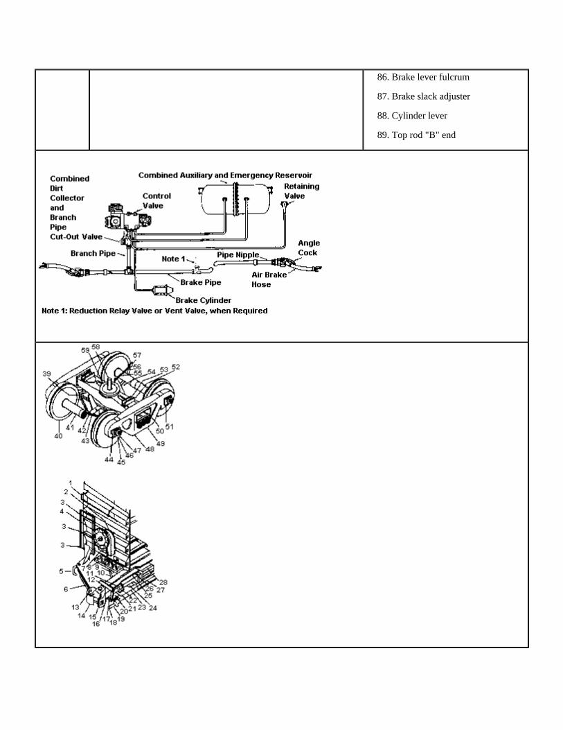
86. Brake lever fulcrum
87. Brake slack adjuster
88. Cylinder lever
89. Top rod "B" end
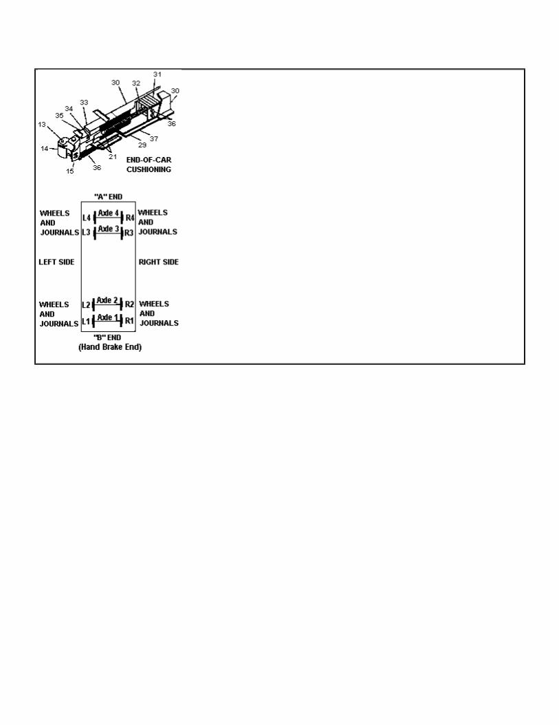

Rule Updated Date
January 20, 2012
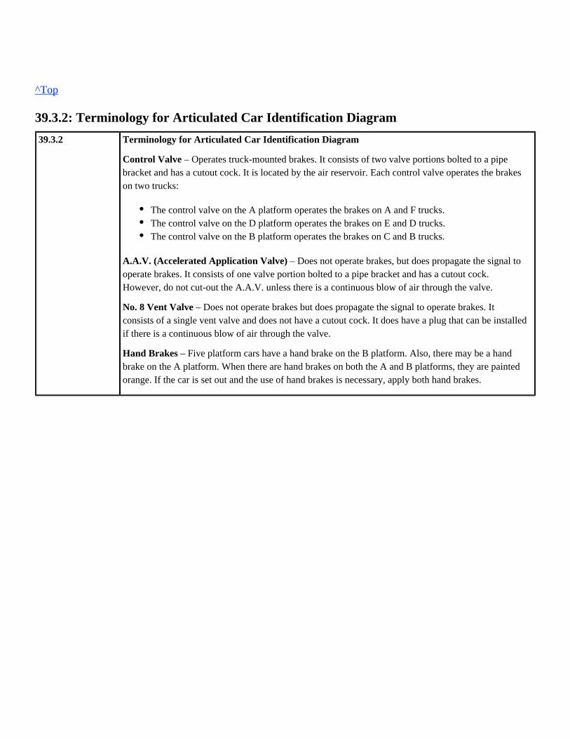
^Top
39.3.2: Terminology for Articulated Car Identification Diagram
39.3.2 Terminology for Articulated Car Identification Diagram
– Operates truck-mounted brakes. It consists of two valve portions bolted to a pipeControl Valvebracket and has a cutout cock. It is located by the air reservoir. Each control valve operates the brakeson two trucks:
– Does not operate brakes, but does propagate the signal toA.A.V. (Accelerated Application Valve)operate brakes. It consists of one valve portion bolted to a pipe bracket and has a cutout cock.However, do not cut-out the A.A.V. unless there is a continuous blow of air through the valve.
– Does not operate brakes but does propagate the signal to operate brakes. ItNo. 8 Vent Valveconsists of a single vent valve and does not have a cutout cock. It does have a plug that can be installedif there is a continuous blow of air through the valve.
– Five platform cars have a hand brake on the B platform. Also, there may be a handHand Brakesbrake on the A platform. When there are hand brakes on both the A and B platforms, they are paintedorange. If the car is set out and the use of hand brakes is necessary, apply both hand brakes.
The control valve on the A platform operates the brakes on A and F trucks.The control valve on the D platform operates the brakes on E and D trucks.The control valve on the B platform operates the brakes on C and B trucks.
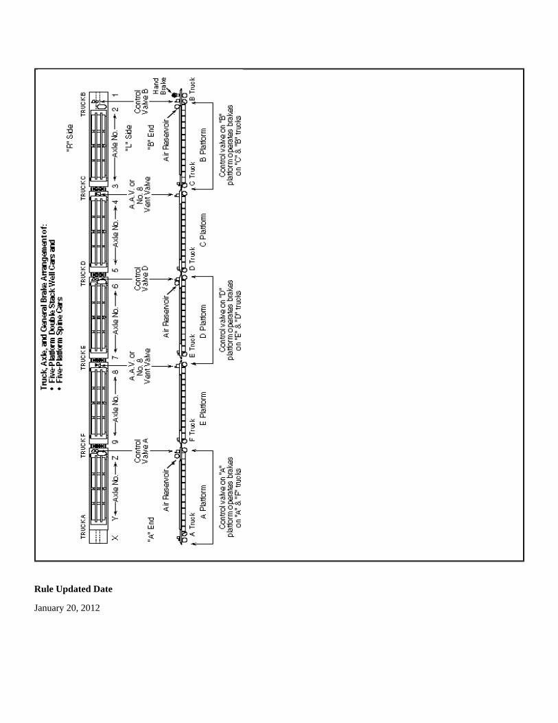
Rule Updated Date
January 20, 2012

^Top
39.3.3: Coupler Diagram
39.3.3 Coupler Diagram
Rule Updated Date
January 20, 2012
^Top
39.3.4: Locomotive Axle, Journal, and Wheel Identification Diagram
39.3.4 Locomotive Axle, Journal, and Wheel Identification Diagram
(To be used when notifying the Dispatcher's Office or others of location of defects, etc.)
To determine axle number, journal number, and wheel number on a locomotive, stand facing the samedirection as the specific locomotive is headed and count axles from the front of that locomotive as axleone, two, etc., and wheels and journals on the right and left sides as R1, R2, etc., and L1, L2, etc.,respectively, as shown in the diagram.
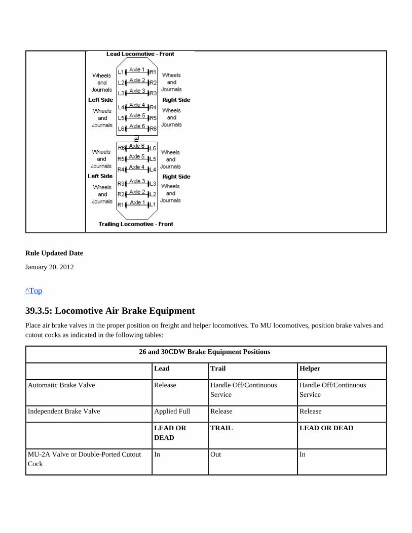
Rule Updated Date
January 20, 2012
^Top
39.3.5: Locomotive Air Brake Equipment
Place air brake valves in the proper position on freight and helper locomotives. To MU locomotives, position brake valves andcutout cocks as indicated in the following tables:
26 and 30CDW Brake Equipment Positions
Lead Trail Helper
Automatic Brake Valve Release Handle Off/ContinuousService
Handle Off/ContinuousService
Independent Brake Valve Applied Full Release Release
LEAD ORDEAD
TRAIL LEAD OR DEAD
MU-2A Valve or Double-Ported CutoutCock
In Out In

CCB Brake Equipment Positions
Lead Trail Helper
Automatic Brake Valve Release Handle Off/Continuous Service Handle Off/Continuous Service
Independent Brake Valve Applied Full Release Release
Air Brake Setup Lead/Cut-in Trail Lead/Cut-out
24RL Brake Equipment Positions
Lead Trail Helper
Automatic Brake Valve Release Release Lap
Independent Brake Valve Applied Full Release Release
Automatic Brake Valve Cutout Valve Open Closed Closed
Rotair Valve Pass Frt Frt Lap Pass or Frt
MU-2A Valve Lead or Dead Trail Lead or Dead
On SD70ACe and C45 locomotives, when the locomotive is other than the controlling locomotive, the automatic brakeNote:valve pin, if available, must be inserted to insure the brake valve handle remains in the proper position. The engineers seat mustbe left secured/locked. This also applies when these locomotives are set out.
Rule Updated Date
January 20, 2012
^Top

Union Pacific Rules Air Brake and Train Handling Rules
GLOSSARY: Glossary
GLOSSARY: GLOSSARY
GLOSSARY
AccelerometerAn indicator that displays the predicted increase or decrease in speed in MPH per minute.
AC LocomotiveAlternating Current (AC) locomotives are equipped with AC traction motors and are not affected by maximum continuouscurrent ratings or short-time operating ratings.
ActuatingUsing a feature of the independent brake valve to charge the actuating pipe from the main reservoir and prevent or release alocomotive brake application initiated from a brake pipe reduction.
Air BrakeA system of compressed air devices controlled manually, electronically, or pneumatically that make the car or locomotive slowdown or stop.
Air Brake EquipmentThe equipment that supplies and exhausts air to and from the brake cylinders but does not include foundation brake gear andhand brakes.
Air Brake HoseThe flexible hose at each end of a car or locomotive that includes a coupling (glad hand) that fits into an identical coupling onthe adjoining car or locomotive. The complete arrangement connects air between the brake pipes of the cars and thelocomotives throughout the train.
Air Brake SystemAll of the devices for operating air brakes to control the speed of and stop a locomotive or train. The system includes theoperating devices, pipes, hoses, fittings, and foundation brake gear.
Air CompressorA locomotive device, powered by the diesel engine or an electric motor, that compresses air for operating the air brakes and allother air-operated devices on locomotives and cars.
Air Compressor Control SwitchA device that controls the loading and unloading of the compressor at the proper main reservoir pressures.
Air Flow Indicator (AFI)A gauge installed in some locomotives that indicates the pressure differential of air flowing into the brake pipe through the
GLOSSARY: GLOSSARY

automatic brake valve. It is not adjustable and cannot be used for air flow method leakage testing of trains or cars. This gaugeis labeled on the face "AIR FLOW INDICATOR" and graduated from 0 to 14 in even numbers (0, 2, 4, 6, etc. to 14).
AFM Indicator or Air Flow Measurement (AFM)A gauge installed in some locomotives that indicates the volume of air in cubic feet per minute (CFM) flowing into the brakepipe through the automatic brake valve. This gauge is calibrated every 92 days and can be used in the Air Flow Method ofleakage testing on trains and cars. It is labeled on the face as "AFM INDICATOR" and is graduated in 10 CFM increments.The gauge is marked at 20, 40, 60, and 80, and lines mark the 10 CFM steps between those numerals.
Air Flow MethodShortened name, or slang, for Air Flow Method of leakage testing. The method of train/car leakage testing to determine theamount of air in cubic feet per minute (CFM) flowing into the brake pipe through the automatic brake valve to maintain desiredpressure against leakage.
Air GaugeAn instrument that indicates air pressure in pounds per square inch (psi).
Alignment Control CouplerSpecially equipped couplers installed on most locomotives that only allow the coupler in buff to move laterally within certainlimits. This equipment minimizes rail turnover, wheel climb, and jackknifing.
Ampere (Amperage, Amps)The standard unit for measuring electric current.
Angle CockA manually operated device located at each end of the brake pipe on locomotives and cars to permit or prevent air flow.
Articulated Multi-platform CarA car with multiple units (segments) that have articulated couplings and in which the units share a common truck.
Automatic Brake ValveA manually operated electronic controller or pneumatic valve on the locomotive that controls the train and engine brakes.
Auxiliary ReservoirA storage volume, charged from the brake pipe, to receive and store air to apply brakes on a car or locomotive. In freight carequipment, the auxiliary reservoir and emergency reservoir are combined in one structure.
"B" End (of car)The end where the hand brake is located unless otherwise identified.
Back-up Valve or HoseA device, either portable or permanently connected to the brake pipe, which controls brakes from the car that it is attached to.The device can apply the brakes with a service or emergency application.
Balanced BrakingThe combined use of train air brakes and dynamic brake to stabilize, increase, or decrease train speed on a descending grade.
Bleed (Bleed-off)Venting air pressure to the atmosphere, such as venting air pressure from the brake cylinder of individual cars, by using therelease valve.

Blended BrakeThe combination of air and dynamic braking by making an automatic service brake application with the throttle in idle.
Brake ApplicationA brake pipe pressure reduction (no matter how made) that causes the control to move to the service or emergency position.
Brake CylinderA cylinder containing a piston. Compressed air forces the piston outward to apply the brakes. When the air pressure is released,the piston returns to its normal position by a release spring coiled around the piston rod inside the cylinder.
Brake PipeThe section of air brake piping of a car or locomotive that supplies the reservoirs. It also connects the piping to allow thelocomotive engineer to control the car brakes. The pipe is 1-1/4" in diameter and extends from one end of the car to the other.At the ends, flexible hoses connect the cars. When a train is made up and all brake pipes on the cars are joined together, theentire pipe line is called the brake pipe.
Brake Pipe GradientThe difference in brake pipe pressure between the locomotive (or source of supply) and the rear car of the train. Brake pipegradients may be:
Brake Pipe PressureThe amount of pressure in pounds per square inch (psi) in the brake pipe (commonly expressed in pounds).
Brake Valve Cutoff ValveA device on locomotives that can cut-out the charging and service functions of the automatic brake valve. This valve alsoproperly positions the brake valve for passenger or freight operation.
Branch Pipe Cutout CockA device on locomotives and cars that isolates the control valve from the brake pipe.
Buff ForcesA term used to describe compressive coupler forces in a train. Buff forces bunch the slack in a train.
Cab CarRailroad rolling equipment intended to provide transportation for members of the general public that is without propellingmotors but equipped with one or more control stands. Locomotive rules apply to cab car operation.
Calendar dayA time period running from one midnight (0001) to the next midnight on a given date.
Code "L"Code "L" is used to identify territories or corridors with relatively light grades and low to moderate track curvature in thecoupler limit tables.
The gradient that exists when the system is fully chargedNormal: The temporary gradient that exists when the system is less than fully charged (For example, the exaggeratedFalse:
difference between the head end and rear end after a release) The temporary condition when the brake pipe pressure is higher at the rear of the train than at the head end ofInverse:
the train (For example, during a service brake application)
Code "H"Code "H" is used to identify territories or corridors with heavier grades and severe track curvature in the coupler limit tables.
Compensated GradeA grade, the curved portion of which has been reduced by an amount sufficient to compensate for the resistance due to thecurvature.
ConsistThe term "consist" usually refers to a set of locomotives coupled together to pull a train. The term may also be used to refer toan entire train—its locomotives and all its cars.
Control ValveA device on locomotives or cars that charges the reservoirs and applies or releases brake cylinder pressure when brake pipepressure reduces or increases.
Controlled Tractive Effort (CTE)CTE mode is a method of limiting maximum tractive effort to 110,000 lbs. at speeds below 14 MPH. CTE mode will affect alllinked remote consists if the controlling locomotive on the remote is so equipped. The effect of CTE mode is shown in SystemSpecial Instructions under Locomotive Information.
Conventional CarA car such as a gondola, hopper, intermodal flat car, box car, bulkhead flat car or single well car. Does not includemulti-platform spine cars or multi-well cars (articulated cars).
Coupler LimitThe location in the train where maximum trailing tonnage allowed for standard or high strength couplers occurs. Helperlocomotive(s) may be used to reduce the amount of tonnage handled by a consist.
DC LocomotiveDirect Current (DC) locomotives are equipped with DC traction motors and are affected by maximum continuous currentratings or short-time operating ratings.
Dead Engine FeatureA device used when a unit is handled dead-in-train. When the dead engine cutout cock is opened, the main reservoirs arecharged from the brake pipe to operate the engine brakes.
Distributed Power (DP)One or more locomotive consists that are remotely controlled from the lead locomotive.
Disturbed TrackA section of passable track that has a temporary speed restriction imposed because various defects or track maintenance haveaffected the integrity of the track.
Draft ForcesA term used to describe tension coupler forces in a train. Draft forces stretch out the slack in a train.
Draft GearThe connection between the coupler rigging and the center sill. This connection receives and cushions the shocks associatedwith in-train forces or coupling.

Drawbar Forces (In-train Forces)Forces at the couplers between cars and/or locomotives that may be either draft (stretched) or buff (compressed), depending ontrain operation.
Dynamic BrakeAn electrical device that converts some of the energy developed by a moving locomotive into an effective retarding force:
Dynamic Brake Holding FeatureA feature of the lead, controlling locomotive that allows dynamic braking effort when a PCS open condition exists.
Dynamic Brake Interlock (DBI)A device that will automatically keep the locomotive brakes from applying when automatic brakes are applied during dynamicbraking.
EqualizationA term used to describe the condition that exists when brake cylinder pressure and auxiliary reservoir pressure become equal.
Electronic Alertness ControlA safety control system that senses the activity of the engineer. If activity or manual resetting of the device does not occurwithin a predetermined time frame, a penalty brake application is initiated.
Electronic Controlled BrakesAn air brake system that can be controlled electronically is referred to as electronically controlled pneumatic brakes or ECP.The ECP systems that are being utilized are overlay brake systems. Overlay means the freight car brake system can be operatedin either ECP or conventional pneumatic mode. All cars in the train must be equipped with ECP to operate in the electric mode.
Emergency ApplicationA rapid reduction of brake pipe pressure that causes the control valves to move to the emergency position and the vent valvesto open. This equalizes auxiliary reservoir, emergency reservoir, and brake cylinder pressures.
Emergency Brake ValveA manually operated device on equipment that initiates an emergency brake application.
A storage volume, charged from the brake pipe, to receive and store air used during emergency brakeEmergency Reservoirapplications and certain recharge features.
Engine/LocomotiveA self-propelled unit of equipment designed for moving other railroad rolling equipment in revenue service including aself-propelled unit designed to carry freight or passenger traffic, or both, and may consist of one or more units operated from asingle control.
– Provide approximately 13,500 lbs. of effort per axle instead of 10,000 lbs. per axleHigh Capacity Dynamic Brakesas other dynamic brake systems.
– A dynamic brake system that provides retardation that is controlledFlat (Grid Control) Dynamic Brake Systemsolely by the position of the dynamic brake lever. Maximum retardation occurs at Position 8.
– A dynamic brake system that provides retardation relative to both speedTaper (Speed Control) Dynamic Brakesand dynamic brake handle position. The higher the speed, the greater the retarding force developed for a given handleposition. At higher speeds, full dynamic brake effort is reached at Position 4.

Telemetry ComponentsEnd-of-Train Telemetry SystemEnd-of-train telemetry device is a radio end-of-train telemetry system that consists of:
A two-way EOT that has been armed (emergency enabled) provides the capability to initiate an emergency brake application atthe rear of the train. An Emergency toggle switch associated with the HEU cab display is used to activate the EOT emergencyvalve. For this to happen, both the head-end and the rear-end units must be equipped for two-way communication and armed(emergency-enabled).
Equalizing ReservoirA small reservoir used in automatic air brake operations. It is only cut-in on the controlling unit. When a brake pipe reductionoccurs, air is drawn from the equalizing reservoir. The reservoir then automatically draws the proper amount of air from thebrake pipe. For this reason, the brake pipe pressure and the equalizing reservoir pressure are always the same, except whenthey are equalizing after a brake pipe reduction or when the brake pipe is charging/recharging.
Foundation Brake GearThe levers, rods, brake beams, etc. that connect the brake cylinder piston rod to the brake shoes so that when air pressure forcesthe piston out, the brake shoes are forced against the wheels.
Full Service ApplicationA brake pipe reduction made only to the point at which the auxiliary reservoir and brake cylinder pressures equalize. From a90-psi fully charged air brake system, service equalization will occur following a 26-psi brake pipe reduction, at 64-psi. Anyfurther reduction in the brake pipe pressure, except an emergency application, will not affect the amount of pressure in thebrake cylinder. Additional reductions greater than 26-psi may result in the loss of the ability to obtain an emergency brakeapplication.
Full Tractive Effort (FTE)Allows locomotive to operate at full tractive effort at speeds below 14 MPH.
Grade (of Track)Grade is other than level track and is usually expressed as a percentage. The percentage is the number of feet the track rises orfalls in a distance of 100 feet. For example, a 1% ascending grade means that the track rises 1 foot in elevation for every 100feet the equipment travels on the track. Unsecured rail equipment may roll on a grade.
Hand BrakeA mechanical arrangement of levers, chains, rods, gears, and fulcrum. When applied manually by wheel or lever, the handbrake forces the brake shoes against the braking surfaces (wheel tread or disc) to control car or locomotive movement.
End-of-train device (EOT) mounted on the trailing coupler of the last car or linked DP consist located on the rear of thetrain.Head-of-train device (HEU) in the locomotive.
Grade designations include the following:
Light Grade: Less than 1.0%Heavy Grade: At least 1.0% for a distance of 3 miles or moreMountain Grade: 2.0% or greater for a distance of 2 miles or more

Head of Train Device (HEU)A radio device located in the locomotive cab that communicates with an End of Train Device (EOT) or distributed power (DP)consist. The HEU displays:
And it provides:
HelperDistributed power or manned helper added to a train to assist movement.
Head End Power (Passenger)Power generated on board the locomotive of a passenger train used for purposes other than propelling the train, such asheating, illumination, ventilation, and air conditioning.
Horsepower Per Trailing Ton (HPT)The total horsepower of all working locomotives divided by the total trailing weight of the train in tons. For example, a trainpowered by 15,000 horsepower and having a trailing weight of 4,285 tons has a 3.5 horsepower per trailing ton ratio (15,000HP divided by 4,285 tons).
Independent Brake ValveA brake valve that controls the locomotive brakes independent of the automatic brake valve handle position.
Independent Pressure Switch (IPS)A device on a locomotive that cancels the extended range portion of dynamic braking or all dynamic braking when a sufficientindependent brake application occurs. This switch prevents the locomotive wheels from sliding because of excessive braking.
Initial TerminalMeans a location where a train is originally assembled.
InterchangeA location where railroads exchange cars and/or locomotives.
Intercom SystemA two-way voice communication system through which voice communication is transmitted and received.
Intermodal EquipmentEquipment designed to carry trailers, containers, or automobiles. Intermodal trains are trains made up entirely of intermodalequipment.
Last car brake pipe pressureLast car motion status (moving or stopped)Marker light status (on or off)EOT battery statusCommunication Status with EOTTwo-way Armed StatusDistance measurement referenced to locomotive movement
Audible alarms pertaining to status changesArming capability to a selected two-way EOTInterface for Manual and Automatic initiated EOT emergencies

Isolation SwitchA switch on diesel electric locomotives that has two or three positions. In the RUN position, the unit is "on the line," respondsto control, and develops power. In the ISOLATION (or Stop-Start) position, the unit is isolated from the consist and does notdevelop power or respond to control.
LinkingThe process of electronically connecting DP or RCL equipment:
Light LocomotiveOne or more units, with or without a caboose, not coupled to cars.
JackknifeExcessive lateral forces caused by heavy buff forces resulting in wheels lifting over the high rail or rail rolling over.
JournalThe part of a rail car axle on which the journal bearing rests or is mounted. Found at each end of each axle of a rail car.
Main ReservoirAn air reservoir on the locomotive for storing and cooling compressed air.
Minimum Continuous SpeedMinimum continuous speed is the slowest speed at which a DC locomotive can operate continuously in Throttle 8. Locomotivetraction motors operating under these conditions develop the highest amperage possible before overheating. The minimumcontinuous speed varies and is indicated by the rating plate on the locomotive.
Minimum ReductionThe first position of the automatic brake valve that initiates a service application of 6 to 8-psi.
Man Down FeatureSafety feature on a remote control transmitter that transmits an emergency message over the radio when RCL transmitter istilted beyond prescribed limits.
Manned HelperA helper controlled by an engineer in the controlling unit of the locomotive helper consist.
Multiple Unit (MU)Lead locomotive followed by one or more locomotives. Cables and hose connections between the locomotives allow control ofthe trailing units from the lead locomotive.
Note: Locomotive(s) handled DIC/Isolated at rear of consist will be considered MU'd when all air hose connections have beenmade and Rule 31.8.4 Locomotive Consist Air Brake Test performed.
MU Cutout Cock (MU-2-A, Dual-Ported Cutout Cock)A device for cutting in or out the independent brake valve.
Non-articulated Multi-platform CarsA car with multiple units (segments) that are connected with solid drawbars. Each unit is a stand-alone unit and does not sharea common truck with another unit.
The controlling lead unit to the controlling distributed power unit on a distributed power trainThe controlling locomotive unit to the remote control transmitter(s)
Off AirNot connected to a continuous source of compressed air of at least 60 pounds per square inch (psi).
OverchargeBrake equipment charged to a higher pressure than the regulating valve is adjusted for or can maintain. In such a condition,brakes on a portion of the train may not release.
PA System (public address system)A one-way voice communication system.
Parking BrakeA Cab Car brake valve that controls the brakes on the lead truck of the Cab Car only and does not have the capability to actuateany brakes applied from the automatic brake valve handle.
Penalty Brake ApplicationAn automatic full service brake application caused by various safety devices.
Pitch and CatchTransferring controls of the locomotive to another linked RCT.
Plug DoorA type of side door used on insulated and refrigerator cars that fits flush with the side of the car when closed.
Positive Stop Protection (PSP)Positive Stop Protection is designed to stop movements before reaching the end of a remote control zone if the RCO fails tocontrol the movement.
Power Cut-off Switch (PCS)An air-operated switch, activated by an emergency or penalty brake application, that drops the engine speed to idle on EMDlocomotives or throttle notch 1 on GE locomotives.
Power Holding FeatureA feature of the lead, controlling locomotive that allows tractive effort to continue for approximately 20 seconds when a PCSopen condition exists. This feature will not function when an emergency application is initiated by either the conductor's or theengineer's brake valve.
Pressure Maintaining BrakingControlling train speed by making enough of a brake pipe reduction to stabilize speed on a grade, then allowing the automaticbrake valve pressure maintaining feature to hold the brake application constant regardless of brake pipe leakage.
Pressure Maintaining FeatureA system designed to overcome brake pipe leakage both in the RELEASE and SERVICE positions of the automatic brakevalve.
Primary Remote Control Operator (Primary Operator)The employee operating the transmitter while controlling a remote control movement.
Qualified Person (Freight)A train service employee given fundamental training on freight car inspections and air brake tests.
Qualified Person (Passenger)A train service employee given fundamental training on passenger car inspections and air brake tests.

Qualified Mechanical Inspector (Carman)A person, such as a carman, who has been given more extensive training that encompasses more detailed inspection andrepairs.
Qualified Maintenance Person (Passenger Car Inspector)A person, such as a carman, who has been given more extensive training that encompasses more detailed inspection and repairsand is qualified to conduct a Passenger Class I Brake Test.
Remote Control LocomotiveA locomotive equipped with radio control, operated by a remote control operator.
Remote Control Operator (RCO)Employee trained in remote control operations who uses an RCT to operate a remote control locomotive and possesses a Class6 or 7 operator's license.
Remote Control Transmitter (RCT)A portable unit attached to an RCO vest. The RCT sends commands to the RC receiver on the locomotive.
Reduction (of the brake pipe)A decrease in brake pipe pressure at a rate and of an amount sufficient to cause a train brake application to be initiated orincreased.
Reduction Relay ValveA device on long cars that helps reduce brake pipe pressure during service and emergency brake applications. The valvecompensates for the added length of brake pipe on long cars.
Regulating ValveThe valve that reduces air pressure from the locomotive's main reservoir to the desired pressure in the brake pipe. Theregulating valve will automatically maintain that pressure when the automatic brake valve is in the RELEASE position.
Retaining ValveA manually operated valve used on cars to exhaust brake cylinder pressure completely or to maintain a predetermined pressure.
Restricted Car LimitsA defined number of cars immediately behind the lead locomotive consist, immediately ahead of and behind an entrainedhelper, or immediately ahead of a rear helper. The number of cars within a restricted car limit can change based on the traintonnage, territory type, and number of powered axles for each power consist.
Restricted Car PlacementWhen rules restrict the placement of cars, each platform or well is to be considered one car.
Service ApplicationWhen brake pipe pressure exhausts at a service rate to apply the train brakes.
Slack ActionMovement of part of a coupled train at a different speed than another part of the same train.
SlugA unit with traction motors but no diesel engine and incapable of propelling itself. The unit receives electrical power through apower cable from an adjacent, specially equipped locomotive. Slugs are used where low speeds and high tractive effort areneeded.
Solid Block (of cars)One or more cars coupled together that:
Split Service ReductionA term describing a method of making an air brake application in two or more steps to produce a more uniform application.
String-LiningCars pulled off the inside of curves, trying to approach a straight line when the train is in draft.
Standard and High Strength CouplersEach car is to be considered equipped with a standard type coupler unless it is known the car is equipped with high strengthcouplers. Coal cars, covered hopper cars, auto rack cars, and cars designed to carry TOFC/COFC are equipped with highstrength couplers. If it is not known that a car is equipped with high strength couplers, it can be determined by looking at thecoupler casting identification located on top of the coupler. A high strength coupler will have the letter "E" or "EX" as the lastcharacter of identification. Examples of high strength coupler identifications are E60HTE, SBE60CE, E60DE, andEF512WEX.
Thermal Cracks (in wheels)Cracks in a railroad wheel, normally caused by heat generated on the tread and flange of the wheel from excessive braking.
Throttle ModulationThe action of adjusting the throttle one notch at a time between idle and position 8 to control train speed without theapplication of air brakes.
Tons per Dynamic Brake Axle (TPDBA)The total gross trailing tonnage of the train divided by the number of axles of locomotives, including helper locomotives,operating in dynamic brake.
When making this calculation, include in the gross trailing tonnage the weight of any locomotive, including a helperlocomotive, not operating in dynamic brake or with dynamic brake cut-out.
Tons per Operative Brake (TPOB)The gross trailing tonnage of the train divided by the total number of cars having operative brakes.
Tons per Equivalent Powered Axle (TPA):
Are charged or have not been off air for more than 4 hoursHave been tested as outlined in Rule 30.10.1 (Procedure for Inspection and Test)Have been inspected as outlined in Rule 1.33 (Inspection of Freight Cars)Have been inspected as outlined in Section III (Inspection) of Instructions for Handling Hazardous Materials
is calculated by dividing the total trailing tonnage by the total equivalent powered axles (includes lead and helperTPApower). The weight of dead or isolated locomotives must be added to the total trailing tonnage before making thiscalculation.
– The maximum tonnage per equivalent powered axle specified over a given route. Trains may not exceedTPA Limitmaximum TPA at origin, unless there is a plan in place to pick up additional power or reduce tonnage (scheduledset-out) prior to reaching the ruling grade. TPA may only be exceeded enroute when authorized by proper authority.Train consist TPA numbers will govern any discrepancies.

Track-Train DynamicsA general term used to describe the interaction of a locomotive and cars with the track structure during the movement of atrain. Track-Train Dynamics are affected by variables such as weather, speed, train make-up, train handling, condition of trackand equipment, grade, curvature, and operating policies.
Transfer Train MovementAn engine with one or more cars that travels between a point of origin and a point of final destination not exceeding 20 miles.Such trains may pick up or set out while enroute to destination.
Tread Build-upTread build-up is the formation of metal on the running surface of a wheel. Tread build-up on a car can occur due to:
UnattendedEquipment is unattended when an employee is not in a position to immediately control the brake system (hand or air brakes).
Attended cars must be properly secured with hand brakes when:
Undesired Emergency (UDE)An unintentional emergency application of train air brakes.
Unit TrainA train made up entirely of cars used to transport coal, grain, ore, potash, molten sulfur, soda ash, phosphate rock, oil, taconite,or other bulk commodities.
Unplanned StopThe shortest stop possible without using an emergency application
Vent ValveA valve attached to the brake system of a car or locomotive. The valve responds to an emergency brake pipe pressure rate ofreduction by venting the brake pipe at each vehicle to the atmosphere. As a result, the emergency application spreadsthroughout the train.
VestibuleThe area of a passenger car that normally does not contain seating and is used for passing from the seating area to side exitdoors.
Wheel SlidingWhen the wheel rotates slower than lengthwise movement dictates.
Failure to remove a hand brakeAir brake system defect on the carRetainer left in the retaining position
Air brakes are not applied in emergency.There are less than 5 cars.Standing on grade exceeding 1%.
Empty Bulk Commodity Unit Train is made up entirely of empty cars.Loaded Bulk Commodity Unit Train is made up entirely of loaded cars.
Wheel SlippingWhen the wheel rotates faster than lengthwise movement dictates.
Yard Test PlantA system of piping and fittings that supplies air at convenient locations to charge and to test cars without a locomotive.Charging pressure must be adjusted to 90-psi.
Rule Updated Date
July 2, 2013
General Order
Effective Date: July 2, 2013
^Top