Embed Size (px)
Citation preview

ENERGY STAR® MULTIFAMILY HIGH RISE PROGRAM Simulation Guidelines Version 1.0, Revision 03 January 2015

January 2015 Version 1.0, Revision 03
ENERGY STAR MFHR Simulation Guidelines Version 1.0, Revision 03 Page 2
Table of Contents i. DEFINITIONS .................................................................................................................... 3 1. SCOPE. .............................................................................................................................. 5 2. OBJECTIVES. ................................................................................................................... 5 3. MODELING GUIDELINES .............................................................................................. 5
3.1 General Approach. ....................................................................................................... 5 3.2 Performance Rating and Documentation Requirements (G1.2 and G1.4) ................... 7 3.3 Simulation Program (Section G2.2) ............................................................................. 9 3.4 Building Envelope: Opaque Assemblies ...................................................................... 9 3.5 Building Envelope: Vertical Fenestration .................................................................. 11 3.6 Lighting (Table G3.1, Section 6) ............................................................................... 12 3.7 Thermal Blocks (Table G3.1, Sections 7, 8 and 9) .................................................... 16 3.8 HVAC ........................................................................................................................ 16 3.9 Domestic (Service) Hot Water Systems (Table G3.1, Section 11) ............................ 20 3.10 Receptacles and other plug loads (Table G3.1, Section 12) .................................... 23 3.11 Elevator Loads. ........................................................................................................ 25 3.12 Ventilation and Infiltration ....................................................................................... 26 3.13 HVAC Distribution Losses ...................................................................................... 28 3.14 Fan Motor Energy .................................................................................................... 29 3.15 Pumps ....................................................................................................................... 31 3.16 Energy Rates ............................................................................................................ 32
APPENDIX A: Referenced Standards and Data Sources (Informative) ............................ 34 APPENDIX B: Description of Performance Path Calculator ............................................. 35

January 2015 Version 1.0, Revision 03
ENERGY STAR MFHR Simulation Guidelines Version 1.0, Revision 03 Page 3
i. DEFINITIONS ASHRAE 90.1-2007: energy standard for buildings, except low-rise residential buildings. Minimum requirements for the energy-efficient design of multifamily buildings over three stories above grade are included within this standard. ASHRAE 90.1-2007 Appendix G (Appendix G): protocols for generating an energy Performance Rating for buildings that exceed the requirements of ASHRAE 90.1-2007 is included within this appendix. As-Built: conditions observed and measured in the completed building. The As-Built energy model must represent the actual observed and measured conditions in the constructed building, excluding envelope leakage and duct leakage of in-unit forced air systems. Baseline Building Design: a computer representation of a hypothetical design based on the proposed building project. This representation is used as the basis for calculating the Baseline Building Performance for rating above-standard design. Baseline Building Performance: the annual energy cost for a building design intended for use as a baseline for rating above-standard design. common space: any spaces within a building that serves a function in support of the residential part of the building that is not part of a dwelling unit. This includes spaces used by residents, such as corridors, stairs, lobbies, laundry rooms, exercise rooms, residential recreation rooms, parking used exclusively by residents, building staff, and their guests. This also includes offices used by building management, administration or maintenance and all special use areas located in the building to serve and support the residents such as day-care facilities, gyms, dining halls, etc. design team: group of professionals responsible for the final design of a building including, but not limited to: the developer, the general contractor, the architect, and design engineers. dwelling unit: a single unit providing complete independent living facilities for one or more persons, including permanent provisions for living, sleeping, eating, cooking, and sanitation. energy neutral: element of the simulation that is kept identical in the Baseline Building Design and Proposed Design. in-unit: term used to describe features in the building that are located within the dwelling units. For example, “in-unit lighting” is used to reference lighting located within the apartments.

January 2015 Version 1.0, Revision 03
ENERGY STAR MFHR Simulation Guidelines Version 1.0, Revision 03 Page 4
local mechanical exhaust: An intermittent or continuously operating exhaust fan that removes air from a conditioned space, such as the dwelling unit’s bathrooms and kitchen, and discharges to the outside. A bathroom is any room containing a bathtub, a shower, a spa, or similar source of moisture. A kitchen is any space containing cooking appliances. nonresidential: spaces in mixed-use buildings other than residential or common space, such as commercial space. Performance Path Calculator: set of spreadsheet calculators provided by the Program to assist energy modelers in generating certain specific data inputs needed to complete the energy model for the Baseline Building Design and Proposed Design as referenced in this document, as well as summarize modeling results. The description of the Performance Path Calculator is included as Appendix B of this document. Performance Rating: percent reduction in predicted annual energy costs across all end-uses when comparing the Proposed Design or As-Built to the Baseline Building Design. Performance Target: minimum Performance Rating required to earn the ENERGY STAR. Proposed Design and As-Built must achieve a Performance Rating of 15% or more to be eligible to earn the ENERGY STAR. Energy cost savings associated with on-site power generation, including cogeneration, photovoltaics, or wind turbines, may not be used to meet the Performance Target of 15%, but may be used to exceed it. prerequisites: minimum program standards set by EPA to restrict the ability of the design team to make performance trade-offs that would allow individual building components to fall below minimum acceptable standards. A Prerequisites Checklist is provided in the Testing and Verification Worksheets. Proposed Building Performance: the annual energy cost calculated for a Proposed Design. Proposed Design: a computer representation of the actual proposed building design or portion thereof used as the basis for calculating the design energy consumption and costs. residential: spaces in buildings used primarily for living and sleeping. Residential spaces include, but are not limited to, dwelling units. residential-associated: see common space ventilation: the process of supplying outdoor air to or removing air from a space by mechanical means. whole-unit ventilation: A mechanical exhaust system, supply system, or combination that provides each dwelling unit with outdoor air each hour at no less than the rate specified in Table 4.1a of ASHRAE 62.2-2007 or, equivalently, Equation 4.1a of ASHRAE 62.2-2007, based on the floor area of the dwelling unit and number of bedrooms.

January 2015 Version 1.0, Revision 03
ENERGY STAR MFHR Simulation Guidelines Version 1.0, Revision 03 Page 5
1. SCOPE.
1.1 General. This document contains the methodology for calculating a Performance Rating for multifamily buildings in EPA’s ENERGY STAR Multifamily High Rise Program (“Program”). This is not a stand-alone document. It is intended to be used as a supplement to the procedures described in ASHRAE 90.1-2007 (or 2010), Appendix G. The ASHRAE 90.1 standard includes a wide range of building types within its scope. As a result, this standard does not address certain characteristics commonly found in high rise multifamily buildings with sufficient specificity to ensure that energy modeling results are consistent from one energy modeler to the next. This document is designed to address these issues so that the assumptions that must be made to complete these energy models are applied logically and consistently based on all of the features typically found in high rise multifamily buildings. 1.2 Instructions. The document is to be used by ENERGY STAR Multifamily High Rise (MFHR) participants and energy modelers to calculate the Performance Rating of the Proposed Design for each building participating in the program. It may be shared with the developer or property owner if requested.
2. OBJECTIVES. 2.1 Ensure a consistent simulation methodology from building to building and from energy modeler to energy modeler based on ASHRAE 90.1-2007(or 2010), Appendix G to evaluate energy efficiency of multifamily buildings. 2.2 Ensure a consistent approach for handling the simulation of components that are not included in Appendix G, or included without the level of detail needed to support the simulation process. 2.3 Address those issues that Appendix G leaves for the “rating authority” to decide. The “rating authority” is the EPA. 2.4 Ensure that the rating process facilitates energy efficient design from the beginning of the design process.
3. MODELING GUIDELINES 3.1 General Approach.
3.1.1 Baseline Building Design Components.

January 2015 Version 1.0, Revision 03
ENERGY STAR MFHR Simulation Guidelines Version 1.0, Revision 03 Page 6
3.1.1.1 Components of the Baseline Building Design shall comply with ASHRAE Standard 90.1-2007 (or 2010) and other applicable national standards as noted in the text and listed in Appendix A of this document. Addenda to the referenced standards may be used, but must be explicitly mentioned in the documentation provided by the energy modeler, including the related modeling implications. 3.1.1.2 End uses that do not exist in the Proposed Design cannot be included in the Baseline Building Design. For example, if the parking lot in the Proposed Design is not lit, then parking lot lighting power allowance cannot be added to the Baseline energy consumption.
3.1.2 Proposed Design Components.
3.1.2.1 Components in the Proposed Design must reflect the actual building components, except where otherwise specified in this document. Components in the Proposed Design must comply with the prerequisites of this Program as well as applicable state and local codes. If components are not installed during construction, (for example appliances or room air conditioners), then such components may not be modeled in the Proposed Design as contributing to energy cost savings.
3.1.3 As-Built Components.
3.1.3.1 Unless otherwise noted in this document, components in the As-Built model must reflect the actual building components, as verified or measured during inspections. At the completion of the project, these same guidelines must be used to calculate the Performance Rating for the As-Built model, by substituting “As-Built” where you find “Proposed Design”. Components that are not required to reflect As-Built conditions within the energy model, such as envelope leakage, are specified in the relevant sections below. Although some required measurements are not incorporated in the energy model, they do have restrictions as described in the prerequisites.
3.1.4 Simulation Methodology.
3.1.4.1 The Baseline Building Design and Proposed Design of buildings in the scope of ASHRAE Standard 90.1-2007 shall be simulated per ASHRAE Standard 90.1-2007 Appendix G and as described in this document. If the Performance Target is based on ASHRAE Standard 90.1-2010, it shall instead be simulated per ASHRAE Standard 90.1-2010 Appendix G.
3.1.4.2 The Baseline Building Design and Proposed Design shall include all dwelling units and common spaces, as defined above, in the building. 3.1.4.3 In mixed use buildings, nonresidential areas such as retail stores or offices open to general public and unrelated to the building’s residential function may be included or excluded from the simulations at the discretion of the energy modeler,

January 2015 Version 1.0, Revision 03
ENERGY STAR MFHR Simulation Guidelines Version 1.0, Revision 03 Page 7
but must be modeled as energy neutral. However, if excluded, the building will not be eligible to receive the Designed to Earn ENERGY STAR logo after approval of the Proposed Design Submittal.
3.1.4.4 Separate Baseline Building Design and Proposed Design models shall be created for each non-identical building in the project. The Performance Rating shall be calculated individually for each such building.
3.1.5 Final Design. The Baseline Building Design and Proposed Design shall be based on the final design of the building, not the initial or preliminary design that was received by the energy modeler from the design team.
3.1.6 Design Changes. The Baseline Building Design may require changes until all the parameters in the Proposed Design that affect the Baseline Building Design are finalized.
3.1.5 Schedules
3.1.5.1 The schedules described within this document, or approved equivalent schedules, must be used. All schedule assumptions that differ from the ones specified in these Simulation Guidelines shall be documented and submitted to EPA for approval. The same schedules must be used in both the Baseline Building Design and Proposed Design unless explicitly allowed otherwise in Appendix G or this document. Any difference in the schedules must be documented.
3.2 Performance Rating and Documentation Requirements (G1.2 and G1.4)
3.2.1 The Proposed Building Performance and Baseline Building Performance must each be calculated as the sum of predicted energy cost by end use. The energy consumption for each end use shall be taken from the report generated by the simulation program as described in Section G1.4 of Appendix G and in this document. 3.2.2 Some modeling software cannot calculate energy usage for all types of technologies proposed for high rise multifamily buildings. Energy use for these features can be determined using separate calculators, custom software, spreadsheets, or other applicable and reasonable means of estimating the energy impact of those features. When calculations of this nature are completed outside of the primary modeling tool, the energy modeler must document both the basis for the calculation and how it was incorporated into the final Performance Rating. Calculations performed outside of the primary modeling tool and not described in this document shall be submitted to the EPA for review and approval. 3.2.3 End-use Energy Consumption used in the Percentage Improvement equation shall be adjusted to incorporate the results of approved calculations done outside of the modeling tool and as described in this document.

January 2015 Version 1.0, Revision 03
ENERGY STAR MFHR Simulation Guidelines Version 1.0, Revision 03 Page 8
3.2.4 Modeling Assumptions that are not explicitly specified in Appendix G or this document shall be documented and submitted to EPA or its designated agent for review and approval. 3.2.5 A summary of the performance calculation requirements are listed below but may differ depending on the software tool being used. For example, some tools may be able to automatically calculate exposure-neutral baseline (steps below), or generate a Performance Rating automatically based on the entered parameters of the Proposed Design.
3.2.5.1 Baseline Building Performance shall be determined as follows: a. Export into a spreadsheet file all total electricity and fuel usages from the
energy modeling software tool, for each of the four Baseline Building Designs (actual orientation, and 90, 180, 270 degree rotations, per Table G3.1 of Appendix G). Exception: Baseline Building Performance may be based on the actual building exposure if it is demonstrated that the building orientation is dictated by site conditions.
b. Show usage of each fuel according to at least the following components: lights, internal equipment loads such as appliances and plug loads, service (and domestic) hot water heating equipment, space heating equipment, space cooling equipment, fans and other HVAC equipment (e.g. pumps), and otherwise meet the requirements of Section G1.4 of Appendix G.
c. Average the results of the four building orientations, for each fuel and per each usage component, if applicable.
d. Adjust the result to include the approved calculations performed outside of the energy modeling software tool.
e. If the energy consumption inputs in steps a-d above were expressed in units other than dollars, then after adjusting the simulation outputs as described above, multiply the result by the appropriate fuel rates. This dollar value ($) is your Baseline Building Performance.
3.2.5.2 Proposed Building Performance is determined as follows: a. Export into a spreadsheet file all total electric and fuel usages from the energy
modeling software tool (only the actual building orientation is required; no rotations).
b. Adjust the result to include the approved calculations performed outside of the energy modeling software tool.
c. Show usage of each fuel by end use. d. If the energy consumption inputs in steps a-c above were expressed in units
other than dollars, then after adjusting the simulation outputs as described above, multiply the result by the same fuel rates as used for the Baseline simulation. This dollar value ($) is your Proposed Building Performance.
3.2.6 Performance Rating. Calculate the Performance Rating as:

January 2015 Version 1.0, Revision 03
ENERGY STAR MFHR Simulation Guidelines Version 1.0, Revision 03 Page 9
100*(Baseline Building Performance - Proposed Building Performance) ÷ (Baseline Building Performance)
3.3 Simulation Program (Section G2.2)
3.3.1 Modeling Requirements. The simulation program must meet the requirements of Appendix G, Section G2.2. Although not limited to this list, examples of programs that meet these requirements are DOE-2, eQUEST, TRACE, HAP and EnergyGauge.
3.4 Building Envelope: Opaque Assemblies
3.4.1 Baseline Surfaces. The properties of the Baseline surfaces shall be determined as follows (using the corresponding sections from ASHRAE 90.1-2010 as needed): a. Requirements are based on the surface type outlined in ASHRAE 90.1-2007
Appendix G, prescriptive envelope requirements from Table 5.5, and detailed surface descriptions from ASHRAE 90.1-2007 Appendix A. For example, the roof in the baseline shall be modeled as insulated entirely above deck, with continuous insulation R-value from Table 5.5 for the appropriate climate zone. Walls above grade shall have steel framing 16” OC, stucco R-0.08 (exterior layer), 0.625” gypsum board R-0.56, cavity and/or continuous insulation from Table 5.5 for the appropriate climate zone and accounting for the thermal bridging, and 0.625” gypsum board R-0.56 (interior layer). Building Envelope Climate Criteria are covered in Appendix B to ASHRAE 90.1-2007.
b. ‘Residential’ envelope requirements apply only to dwelling units. Examples of spaces that are considered ‘nonresidential’ for the purpose of envelope requirements include common space such as corridors, stairwells, and lobbies, and commercial spaces being included in the energy model.
c. Per ASHRAE 90.1-2007 Section 5.5.2, if a building contains any semiheated or unconditioned space, then the semi-exterior building envelope of the Baseline Building Design shall comply with the requirements for ‘Semiheated’ space in Tables 5.5. For more information on space types and envelope definitions, see definition of ‘space’ and Figure 5-5 in ASHRAE 90.1-2007, or 5-C of the 90.1-2007 User’s Manual. For example, for the purpose of identifying exterior envelope requirements, indirectly conditioned basements and non-vented crawlspaces with insulated walls, rather than ceilings, generally will still be considered ‘conditioned space’ and therefore the ‘nonresidential’ requirements apply.
d. The surface properties for existing buildings that undergo major renovations shall reflect existing conditions prior to any revisions that are part of the scope of work being evaluated, per Table G3.1 Section 5(f) of Appendix G. This requirement applies to the thermal properties and areas of the different envelope components. For example, if window area was changed as part of the renovation, the pre-retrofit window area shall be modeled in the baseline, and post-retrofit window area shall be modeled in the Proposed Design. This requirement does not apply to envelope air-tightness – the same air leakage must be modeled in the baseline and proposed models.

January 2015 Version 1.0, Revision 03
ENERGY STAR MFHR Simulation Guidelines Version 1.0, Revision 03 Page 10
e. Spandrel areas of curtain wall systems are modeled as opaque assemblies in the Baseline and follow the U-factor requirements for Above-Grade steel-framed walls.
3.4.2 F-factor. If the energy modeling software tool does not allow input of the perimeter heat loss factor (F-factor), then the slab-on-grade construction that corresponds to the F-factor shall be modeled as is appropriate to the software tool being used. If the slab-on-grade insulation in the Proposed Design is a permitted method, as described in Section 5.3.1.5 of the Standard 90.1 User’s Manual, model slab-on-grade as energy neutral. If the slab-on-grade insulation is not a permitted method, model as uninsulated in the Proposed Design. 3.4.3 Thermal Bridging. Components in the Proposed Design shall be modeled in accordance with their actual properties and accounting for thermal bridging, as described in ASHRAE 90.1-2007 Appendix A. 3.4.4 Shading Devices. Automatically-controlled fenestration shades or blinds and permanent shading devices (side fins, overhangs, balconies) may be accounted for to calculate energy savings in Proposed Design (per Appendix G). 3.4.5 HVAC Penetrations. Through-wall AC sleeves and PTAC/PTHP penetrations must be modeled in the Proposed Design with the U-factor required in Table 5-5 for vertical glazing with metal framing (all other). Although an insulated cover is required for the through-wall AC units by the Program prerequisites, the insulated cover is not used every day and may not be included in the model. 3.4.6 Doors that are more than one-half glass are considered fenestration, per Section 3 of ASHRAE 90.1-2007, and shall be modeled with properties required for vertical glazing from ASHRAE 90.1 Table 5-5 in the Baseline Building Design, as described in Section 3.7 of this document. 3.4.7 Unique envelope assemblies such as projecting balconies, perimeter edges of intermediate floor slabs, concrete floor beams over parking garages, and roof parapets, shall be separately modeled in the Proposed Design, per Appendix G Table G3.1, Section 5(a). A weighted average of the U-factors of these assemblies is acceptable in the simulation. Projected balconies and perimeter edges of intermediate floor slabs are considered to be a wall, per wall definition in Section 3 of ASHRAE 90.1-2007, and shall be modeled in the Baseline Building Design as having the U-factor required in Table 5-5 for exterior steel-frame walls. 3.4.8 Shelf Angles. The Proposed Design model must account for thermal bridging through portions of the wall assembly where shelf angles or other continuous metal fastened to the wall are used. Where those conditions exist (see Figure 1), the insulation cannot contribute to the assembly U-value for those areas. An overall U-value shall be calculated based on an area weighted average of the thermal properties. For example, if the U-value of a wall assembly is U-0.064 for portions where there is rigid insulation and cavity insulation, the U-value for the areas thermally bypassed by

January 2015 Version 1.0, Revision 03
ENERGY STAR MFHR Simulation Guidelines Version 1.0, Revision 03 Page 11
the shelf angle could be reduced to U-0.097, if the rigid insulation is ignored. If the vertical component of the shelf angle comprises 5% of the vertical wall area, the overall U-value decreases to U-0.066 (U=0.064*0.95+0.097*0.05).
Figure 1: Wall construction utilizing shelf angle
Example: The vertical portion of the wall thermally bypassed by the shelf angle (the red line in Figure 1) must be treated as having no rigid insulation when calculating the weighted average thermal properties of the wall in the Proposed Design.
3.5 Building Envelope: Vertical Fenestration
3.5.1 Fenestration. Per Appendix G, fenestration area shall be distributed on each face of the building in the same proportion as the Proposed Design, without exceeding 40% of gross above-grade wall area. See ASHRAE 90.1-2007 for definition of “fenestration.”
3.5.1.1 Baseline Fenestration properties shall be determined as follows:
3.5.1.1.1 When the Proposed Design is a wood-frame building, properties of fenestration in the baseline shall be based on prescriptive requirements of ASHRAE 90.1-2007 for vertical glazing with nonmetal framing. For all other building types, properties of fenestration shall be based on prescriptive requirements for the applicable metal framing. ASHRAE 90.1-2007 requirements for vertical glazing are shown in Tables 5.5-1 through 5.5-8 based on the framing material.

January 2015 Version 1.0, Revision 03
ENERGY STAR MFHR Simulation Guidelines Version 1.0, Revision 03 Page 12
3.5.1.1.2 For gut rehabilitation projects, the Baseline Building Design shall reflect existing conditions prior to any revisions that are part of the scope of work being evaluated, as described in building envelope section of Table G3.1 of Appendix G.
3.5.1.2 Proposed Fenestration. For the Proposed Design, the properties of fenestration specified in the drawings shall be used. These properties must include rated U-factor and SHGC shown on the National Fenestration Rating Council (NFRC) label. NFRC rating reflects the overall performance of the fenestration assembly and includes both frame and glazing of the standard size window. Certification provided by the installer or supplier listing the assembly U-factor and SHGC can be used in lieu of NFRC labels, provided that they comply with Section 5.8.2.2, 5.8.2.4 and 5.8.2.5 of ASHRAE 90.1-2007. Results from Lawrence Berkley National Laboratory’s WINDOW software or NFRC’s CMAST may also be used in lieu of NFRC labels. 3.5.1.3 Partially Glazed Doors. Modeling of partially glazed doors:
3.5.1.3.1 Doors that are more than one-half glass: a. The entire door area shall be counted as vertical fenestration when calculating the
vertical fenestration-to-wall ratio. b. The door shall be modeled as a single fenestration unit in both the Baseline
Building Design and Proposed Design. c. The door U-factor and SHGC in the Baseline Building Design shall be
determined based on requirements for vertical fenestration in Tables 5.5-1 through 5.5-8, based on the applicable climate zone.
d. In the Proposed Design, the door U-factor and SHGC shall be modeled as per the NFRC label for the door specified in the final design.
3.5.1.3.2 Doors that have glazing area of 50% or less: a. Only the glazed portion of the door shall be included when calculating the
vertical fenestration-to-wall ratio. b. Use one of the following options to model the door:
1. Model the entire door as opaque in the Baseline Building Design and Proposed Design. The baseline door U-factor shall be modeled based on the ASHRAE 90.1-2007 requirements for opaque doors of appropriate type1. The proposed door U-factor shall be modeled as per the NFRC label. 2. Model the Baseline Building Design with a door of identical distribution of opaque/glazed area to the proposed door and apply the ASHRAE 90.1-2007 requirements for opaque doors of appropriate type to the opaque area and the U-factor and SHGC for the appropriate window frame type to the glazing area. The proposed door U-factor shall be modeled as per the NFRC label.
3.6 Lighting (Table G3.1, Section 6)
3.6.1 General.
1 The intent of this procedure is to simplify the modeling requirements for doors with less than 50% glazing area and not to create an energy penalty in the analysis for doors with less than 50% glazing area.
January 2015 Version 1.0, Revision 03
ENERGY STAR MFHR Simulation Guidelines Version 1.0, Revision 03 Page 13
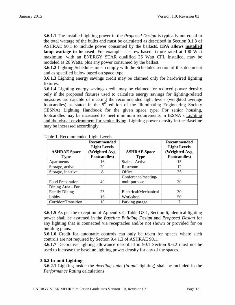
3.6.1.1 The installed lighting power in the Proposed Design is typically not equal to the total wattage of the bulbs and must be calculated as described in Section 9.1.3 of ASHRAE 90.1 to include power consumed by the ballasts. EPA allows installed lamp wattage to be used. For example, a screw-based fixture rated at 100 Watt maximum, with an ENERGY STAR qualified 26 Watt CFL installed, may be modeled as 26 Watts, plus any power consumed by the ballast. 3.6.1.2 Lighting Schedules must comply with the Schedules section of this document and as specified below based on space type. 3.6.1.3 Lighting energy savings credit may be claimed only for hardwired lighting fixtures. 3.6.1.4 Lighting energy savings credit may be claimed for reduced power density only if the proposed fixtures used to calculate energy savings for lighting-related measures are capable of meeting the recommended light levels (weighted average footcandles) as stated in the 9th edition of the Illuminating Engineering Society (IESNA) Lighting Handbook for the given space type. For senior housing, footcandles may be increased to meet minimum requirements in IESNA’s Lighting and the visual environment for senior living. Lighting power density in the Baseline may be increased accordingly. Table 1: Recommended Light Levels
ASHRAE Space Type
Recommended Light Levels
(Weighted Avg. Footcandles)
ASHRAE Space Type
Recommended Light Levels
(Weighted Avg. Footcandles)
Apartments 16 Stairs - Active 15 Storage, active 20 Restroom 12 Storage, inactive 8 Office 35
Food Preparation 40 Conference/meeting/multipurpose 30
Dining Area - For Family Dining 23 Electrical/Mechanical 30 Lobby 16 Workshop 50 Corridor/Transition 10 Parking garage 7
3.6.1.5 As per the exception of Appendix G Table G3.1, Section 6, identical lighting power shall be assumed in the Baseline Building Design and Proposed Design for any lighting that is connected via receptacles and/or not shown or provided for on building plans. 3.6.1.6 Credit for automatic controls can only be taken for spaces where such controls are not required by Section 9.4.1.2 of ASHRAE 90.1. 3.6.1.7 Decorative lighting allowance described in 90.1 Section 9.6.2 must not be used to increase the baseline lighting power density for any of the spaces.
3.6.2 In-unit Lighting 3.6.2.1 Lighting inside the dwelling units (in-unit lighting) shall be included in the Performance Rating calculations.

January 2015 Version 1.0, Revision 03
ENERGY STAR MFHR Simulation Guidelines Version 1.0, Revision 03 Page 14
3.6.2.2 In the Baseline Building Design, in-unit lighting power density of 1.1 W/ft2 shall be incorporated into the model. 3.6.2.3 In the Proposed Design, in-unit lighting power density of 1.1 W/ft2 shall be modeled for rooms or portions of the rooms with no specified hardwired lighting. Where hardwired in-unit lighting is specified in the Proposed Design, the actual installed lighting power density shall be modeled. This lighting power density must take into account the total effective wattage of the installed fixtures and floor area of rooms or portions of the rooms in which they are intended. Hardwired fixtures in rooms, such as bedrooms and living rooms, that may be supplemented by lighting that is connected to receptacles must be estimated to provide illumination at a rate of no more than 3 ft2 per Watt. 3.6.2.4 The savings shall be modeled as described on the In-unit Lighting worksheet of the Performance Path Calculator. 3.6.2.5 Baseline and Proposed Design lighting inside dwelling units shall be modeled as lit for 2.34 hours per day. Balcony lighting shall use the same schedule as the dwelling units. No schedule-based performance credits may be claimed for lighting inside dwelling units.
3.6.3 Interior Lighting Except In-unit Lighting
3.6.3.1 Lighting shall be simulated as described in Table G3.1 of Appendix G, using either the building area or space-by-space method. If the Building Area method is used, then the Baseline power density of 0.7 W/ft2 (as per Table 9.5.1, for “Multifamily”) shall be used for all non-dwelling unit spaces. If the space-by-space method is used, then the Baseline Building Design power density in non-dwelling unit spaces shall be modeled as per Table 9.6.1 of ASHRAE 90.1. As per ASHRAE 90.1-2007 Section 9.6.1(a), for types of building spaces not listed in Table 9.6.1, selection of a reasonable equivalent type shall be permitted. For the spaces below, the equivalent space type that must be used has been established, and the lighting power density has been listed for your convenience. For rooms that include more than one space type such as a large basement space with part of the area used to house electrical/mechanical equipment and the rest used for storage, apply the lighting power density to the appropriate square footage and model the weighted average.
Table 2: Space Type Mapping Space Type LPD (W/ft2) Space Type LPD (W/ft2) Computer Room 1.2 Laundry Room 1.3 Lounge/Recreation 1.2 Janitor Closet 0.8 Exercise Room 0.9 Community Room 1.2 Trash Chute/Room 0.8 Elevator (interior) 1.3 Retail 1.7 Tenant Storage 0.3
3.6.3.2 Lighting power trade-offs (as per Section 9.5.1 (d) and 9.6.1 (d)) are allowed only between the areas that have hardwired lighting specified on the Proposed Design drawings. If lighting is specified for only a portion of the space, then the ASHRAE 90.1 lighting power allowance must be assigned to the remainder of the

January 2015 Version 1.0, Revision 03
ENERGY STAR MFHR Simulation Guidelines Version 1.0, Revision 03 Page 15
space (for which the lighting is not specified on the drawings) in both Baseline Building Design and Proposed Design. The Interior Lighting worksheet of the Performance Path Calculator shall be used to calculate interior lighting power trade-offs. 3.6.3.3 Automatic lighting controls are a Baseline and Proposed Design requirement for all spaces listed in ASHRAE 90.1 Section 9.4.1.2a, which, per these Guidelines, include community rooms and computer rooms. Performance credit may be claimed in the Proposed Design for installing automatic controls where such controls are not required, including but not limited to, janitor closets, laundry rooms, offices, public restrooms, trash/refuse rooms, corridors, stairwells, elevators and lobbies. Appendix G Table G3.2, which describes the allowable lighting power adjustments for automatic controls, is replaced with the following table.
Table 3: Allowed Lighting Power Adjustment Automatic Control Device Space Type Power Adjustment Percentage Occupancy sensor Hallways/Corridors
Stairwells All other spaces
25%(1) 35% 10%(2)
Occupancy sensor and programmable timing control
All spaces Same as with occupancy sensor only for the appropriate space type above, or per Table G3.2
(1) 25% power reduction in Hallways per 2005 Building Energy Efficiency Standards of California Energy Code, Section 146 (2) Appendix G, Table G3.2.
3.6.3.4 Baseline lighting in corridors, stairwells and lobbies shall be modeled as lit for 24 hours per day. 3.6.3.5 Hours of operation of Baseline lighting fixtures in areas not identified above may be estimated by the energy modeler based on occupancy type of each space, and shall reflect the mandatory control requirements of ASHRAE 90.1-2007 Section 9.4.1.2. 3.6.3.6 The lighting schedule for the Proposed Design may be adjusted to account for non-mandatory lighting controls in common spaces as described above. Performance credit can be taken either by reducing modeled Lighting Power Density (LPD) or by reducing lighting hours of operation, as described in Appendix G Table G3.1 Section 6c.
3.6.4 Exterior Lighting.
3.6.4.1 Exterior lighting that is connected to the site utility meters, (e.g., pole fixtures for walkways and parking, exterior lighting attached to the building) shall be included in the Baseline Building Design and Proposed Design. Exterior lighting performance credit may be claimed only for the Tradable Surfaces described in Table 9.4.5 for which lighting is specified on the drawings. For example, if the parking lot in the Proposed Design is not lit, then no parking lot lighting power shall be modeled in either the Baseline Building Design or Proposed Design. In addition, performance credit can only be modeled if associated with energy-efficiency, rather than a

January 2015 Version 1.0, Revision 03
ENERGY STAR MFHR Simulation Guidelines Version 1.0, Revision 03 Page 16
decrease in illumination. Per Section 9.4.5, building façade lighting in the Proposed Design may not exceed the Baseline allowance by more than 5%. Lighting specified for apartment balconies can be evaluated as Tradable, using “Other doors”, or as Nontradable, using “Building façades”. Use the Exterior Lighting worksheet of the Performance Path Calculator for exterior lighting calculations. 3.6.4.2 Baseline exterior lighting shall be modeled as lit for no more than 12 hours per day. This includes savings due to photosensors that are required per ASHRAE 90.1-2007 Section 9.4.1.3.
3.7 Thermal Blocks (Table G3.1, Sections 7, 8 and 9)
3.7.1 Requirements 7(b) and 9 of Table G.3.1 in Appendix G are not required in the MFHR program. The referenced sections disallow aggregation of corner units with other dwelling units and disallow aggregation of units that have different orientation and/or are adjacent to different types of surfaces (e.g. roof or slab). Under these guidelines, this simplification is allowed but not required. 3.7.2 All other Thermal Blocks modeling requirements outlined in Table G3.1 must be followed. For example, common spaces, utility areas and other non-living areas must be modeled as separate thermal blocks. 3.7.3 The thermal block configuration must remain identical between the Baseline Building Design and Proposed Design building models.
3.8 HVAC
3.8.1 Every space that is modeled as cooled in the Proposed Design simulation shall also be modeled as cooled in the Baseline Building Design. Likewise, every space that is modeled as heated in the Proposed Design simulation shall also be modeled as heated in the Baseline Building Design. Unconditioned and semi-heated spaces shall also match between the Proposed Design simulation and Baseline Building Design.
a. Model the entire living (including all dwelling unit) space, as well as offices, community rooms and other conditioned spaces, except as described below, as heated and cooled.
b. Do not model cooling in corridors and utility spaces such as mechanical rooms, laundry rooms, etc. unless the spaces are cooled in the Proposed Design. Per addendum dn to ASHRAE 90.1-2007, such thermal zones shall be modeled using constant volume Heating and Ventilation systems in the Baseline Building Design. The heating source shall be warm-air furnace, gas-fired, if the building’s predominant heating source is Fossil Fuel, Fossil/Electric Hybrid, or Purchased Heat, and warm-air furnace, electric resistance in other cases. System design supply airflow rates for these baseline systems shall be based on the temperature difference between a supply air temperature setpoint of 105°F and the design space heating temperature setpoint; the minimum outdoor air flow rate; or the air flow rate required to comply with applicable codes or accreditation standards, whichever is greater. Each thermal block shall be modeled with a separate HVAC system and the following baseline fan power:
Pfan,supply = CFMs * 0.3.

January 2015 Version 1.0, Revision 03
ENERGY STAR MFHR Simulation Guidelines Version 1.0, Revision 03 Page 17
Pfan,supply electric power to supply fan motor (watts) CFMs the baseline system maximum design supply fan airflow rate in cfm
3.8.2 The Baseline and Proposed HVAC system shall be modeled as per Appendix G, and as clarified in the first note below Appendix G Table G3.1.1A, “…Residential building types include dormitory, hotel, motel, and multifamily.” Following this note, common spaces that are essential to the building’s residential function, including but not limited to corridors and stairwells, must be modeled with residential baseline HVAC system type (System 1 or 2 only) depending on the predominant fuel source in the building, except as allowed in 3.8.1. Appendix G exception G3.1.1(a) that allows the use of additional system types for nonpredominant conditions if they total more than 20,000 ft2, only applies to heating source, not space function. Baseline HVAC System Types 3-8 may not be used, except in appropriate nonresidential spaces that exceed 20,000 ft2. Example 1: 25 story multifamily building heated predominantly with gas has 1,000 ft2 of common space on each floor, including corridors, trash rooms, and stairwells. Together, these spaces account for 25,000 ft2. Corridors are heated with gas and cooled. Stairs are heated with electric resistance but not cooled. What baseline system type should be modeled for the common spaces? Correct Approach: Apartments and corridors are modeled with Baseline HVAC System 1-PTAC. Stairs that are heated but not cooled are modeled with Heating and Ventilation System as described in 3.8.1, which results in Baseline HVAC System 11, not 10. Incorrect Approach: Common spaces are modeled with baseline System 7 following exception G3.1.1(a), since they account for over 20,000 ft2 and cover more than 5 floors. Example 2: 25 story multifamily building heated predominantly with electricity has 1,000 ft2 of common space on each floor, including corridors, trash rooms, and stairwells. Together, these spaces account for 25,000 ft2. Corridors are heated with gas and cooled, and account for 21,000 ft2. Stairs are heated with electric resistance but not cooled. What baseline system type should be modeled for the common spaces? Correct Approach: Apartments are modeled with Baseline HVAC System 2-PTHP. Stairs that are heated but not cooled are modeled with Heating and Ventilation System as described in 3.8.1, which results in Baseline HVAC System 10 since the building’s predominant heating source is electric. Corridors can use Appendix G exception G3.1.1(a) in order to model Baseline HVAC System 1-PTAC in the corridors of the Baseline Building Design.

January 2015 Version 1.0, Revision 03
ENERGY STAR MFHR Simulation Guidelines Version 1.0, Revision 03 Page 18
Example 3: 25 story multifamily building with electric heat pumps serving the apartments and corridors are heated with gas, but provide ventilation directly to the apartments. What baseline system type should be modeled for the apartments?

January 2015 Version 1.0, Revision 03
ENERGY STAR MFHR Simulation Guidelines Version 1.0, Revision 03 Page 19
Correct Approach: This qualifies as fossil/electric hybrid and therefore apartments and corridors are modeled with Baseline HVAC System 1-PTAC. 3.8.2.1 For buildings with fossil fuel, fossil/electric hybrid, or purchased heating in the Proposed Design, the Baseline HVAC system type shall be modeled as a packaged terminal air conditioner (PTAC) with a constant volume fan control and a hot water natural draft fossil fuel boiler. As required by G3.1.3.2, the Baseline HVAC system shall be modeled as having a single boiler if the boiler serves a conditioned floor area of 15,000 ft2 or less. If the Baseline HVAC system serves more than 15,000 ft2 of conditioned space, the HVAC system shall be modeled as having two equally sized boilers. 3.8.2.2 For electric and other heating sources, a packaged terminal heat pump (PTHP) shall be used in the Baseline (DX heating instead of a boiler) and shall be modeled with electric auxiliary heat controlled as required by G3.1.3.1. The electric auxiliary heat may not be used in the model at temperatures above 40ºF and the PTHP must be modeled to allow operation in conjunction with the auxiliary heat at temperatures of 25ºF and higher. Below 25ºF, only the auxiliary heat should be modeled. For example, for eQUEST users, set “Minimum HP Heat Temp” to 25ºF and “Maximum HP Supp Temp” to 40ºF. 3.8.2.3 If heating is installed in a garage for snow/ice melting systems or freeze protection for piping, energy costs associated with these heating systems must be included in the Proposed Design, but not the Baseline. 3.8.3 All Baseline HVAC equipment shall be modeled using the minimum efficiency levels as described in Section 6.4. The Baseline equipment capacities shall be oversized by 15% for cooling and 25% for heating as required by G3.1.2.2. The Proposed Design equipment shall be modeled using the capacity and supply airflow of the equipment selected; it cannot use default or calculated values from the software. In all cases, the same modeling method and/or efficiency units shall be used in the Baseline and Proposed model. For example, if thermal efficiency (not AFUE or combustion efficiency) is used in the Baseline Building Design, then thermal efficiency (not AFUE or combustion efficiency) shall also be used for the Proposed Design. The same rule applies to SEER / EER input for cooling equipment. 3.8.4 If the HVAC system efficiency for the Baseline Building Design or Proposed Design is given as SEER and the EER rating is not available from manufacturer’s data and the approved simulation tool does not automatically perform SEER to EER conversion, the equivalent EER for the model must be calculated as follows:
All Equipment: EER = –0.02 x SEER2 + 1.12 x SEER
Similarly, HSPF must be converted to COP as follows, and further adjusted to remove fan energy if needed (use Performance Path Calculator):

January 2015 Version 1.0, Revision 03
ENERGY STAR MFHR Simulation Guidelines Version 1.0, Revision 03 Page 20
All Single Package Equipment: COP = 0.2778 x HSPF + 0.9667 Split Systems < 65,000 Btu/h: COP = -0.0255 x HSPF2 + 0.6239 x HSPF All other Split Systems: COP = 0.4813 x HSPF – 0.2606
3.8.5 Baseline hydronic system shall be modeled as described in Appendix G, including section G3.1.3.2 - G3.1.3.6. 3.8.6 Setpoint temperature of 72ºF and setback temperature of 70ºF shall be used for heating. Setpoint temperature of 78ºF and setback temperature of 80ºF shall be used for cooling. The Baseline Building Design must have setback for both heating and cooling. The following hourly schedule shall be used to simulate setback control:
3.9 Domestic (Service) Hot Water Systems (Table G3.1, Section 11)
3.9.1 Equipment Type and Efficiency 3.9.1.1 Baseline and Proposed system type, capacity and fuel shall be the same as specified in the Proposed Design unless a combination heating/hot water system is used in the final design. In this case, separate stand-alone systems for both heating and hot water meeting the minimum efficiency requirements for each system shall be modeled as the Baseline system. The requirements are as described in Appendix G Table G3.1 Section 11. 3.9.1.2 Baseline system efficiency shall meet the requirements in Section 7.4.2 of ASHRAE 90.1-2007. 3.9.1.3 Water heater efficiency may be described through different parameters including thermal efficiency, combustion efficiency, stand-by loss, recovery efficiency, energy factor, etc. The same units of efficiency shall be used in Baseline Building Design and Proposed Design. If modeling software requires the input of more than one efficiency type (for example Recovery Efficiency and Energy Factor), but only one efficiency type is provided in ASHRAE 90.1-2007 or manufacturer specifications, then the same algorithm shall be used to generate the missing efficiency for both the Baseline Building Design and Proposed Design. All such conversions must be documented and submitted with the model. 3.9.1.4 Unfired storage tank insulation in the Baseline Building Design shall be R-12.5, per ASHRAE 90.1 Table 7.8.
3.9.2 Hot Water Demand.
3.9.2.1 Baseline Hot Water Demand. Hot water demand in the Baseline Building Design shall be determined based on the number of occupants in the building when fully occupied assuming one person per bedroom.
Hour of day 1 2 3 4 5 6 7 8 9 10 11 12 13 14 15 16 17 18 19 20 21 22 23 24 Heating set-point °F
70 70 70 70 70 70 70 72 72 72 72 72 72 72 72 72 72 72 72 72 72 72 72 70
Cooling set-point °F
78 78 78 78 78 78 78 78 78 80 80 80 80 80 80 78 78 78 78 78 78 78 78 78

January 2015 Version 1.0, Revision 03
ENERGY STAR MFHR Simulation Guidelines Version 1.0, Revision 03 Page 21
a. Per-person consumption of 12/25/44 gal/day shall be used based on low/medium/high usage determined based on appropriate occupancy demographics. Low per-person values are associated with buildings having such occupant demographics as all occupants working, seniors, and middle income. High usage is associated with high percentages of children, low income, public assistance, or no occupants working, and can only be used if the building qualifies as affordable housing. b. Hot water consumption of clothes washers and dishwashers is not included in the per-person usages above, and shall be added according to the calculations described below.
3.9.2.2 Low-flow Fixtures. As low-flow fixtures are required by the prerequisites, hot water demand in the Proposed Design may be reduced to reflect the lower flow rates of the installed fixtures than required by the Energy Policy Act 1992 (EPACT 1992). The adjusted demand may be calculated as follows:
ProposedHWDemand[Gal/day]=BaselineHWDemand*(0.36+0.54*LFS/2.5+0.1*LFF/2.5)
Where: LFS [GPM80psi] = rated flow rate of the low-flow showerheads specified on the drawings LFF[GPM80psi] = rated flow rate of the low-flow faucets specified on the drawings
3.9.2.3 ENERGY STAR Dishwashers. Water savings from ENERGY STAR dishwashers may be calculated as follows:
3.9.2.3.1 Assume proposed water consumption of 860 gal/year per ENERGY STAR dishwasher [this default is used by EPA for ENERGY STAR dishwasher]. 3.9.2.3.2 Calculate annual per-unit hot water demand reduction by subtracting annual hot water usage of the Proposed dishwasher from 1290 gal/year for standard dishwasher [this default is used by EPA for conventional dishwashers]. 3.9.2.3.3 Divide annual per unit savings calculated in the previous step by 365 and multiply by the number of dishwashers in the building to obtain total daily savings for the building. 3.9.2.3.4 Subtract total daily savings from ProposedHWDemand to obtain adjusted daily demand of the Proposed Design. 3.9.2.3.5 Use the DHW Demand worksheet of the Performance Path Calculator for reduced hot water demand calculations.
3.9.2.4 Clothes Washer Hot Water Usage. Determine hot water usage by each residential clothes washer in Baseline and Proposed Design as follows:
Baseline Design
Hot Water Gal/yr Proposed Design Hot Water Gal/yr
In-unit clothes washer 0.2*12,179 0.2*5,637
Common space clothes washer 0.2*29,515 0.2*13,661
0.2 = estimated ratio of hot water to total water consumed per year. Values based on annual water consumption of conventional and ENERGY STAR clothes washers, from EPA Savings Calculator for Clothes Washers.

January 2015 Version 1.0, Revision 03
ENERGY STAR MFHR Simulation Guidelines Version 1.0, Revision 03 Page 22
Usage assumptions used by EPA for commercial clothes washers are based on 950 loads/year.
3.9.2.4.1 Convert annual hot water consumption calculated above to hourly values using appropriate hourly load profile as recommended by the energy modeling software tool.
3.9.3 Water Savings. In addition to energy savings associated with reduction in water usage, any measure that results in water savings shall be included in the recommended list of measures. The following guidelines indicate how these measures shall be treated to determine associated savings. Detailed calculations can be found in the Water Savings worksheet of the Performance Path Calculator.
3.9.3.1 All measures that reduce water usage are included in the list of proposed measures. 3.9.3.2 Water savings shall be documented but are not factored into the Performance Target. For example, low-flow toilets can be included in the proposed measures, but do not impact the Performance Target. Energy savings associated with reduced hot water use from low-flow showerheads can contribute to the Performance Target. 3.9.3.3 Water cost savings for all measures may be calculated as follows:
1. Begin by calculating baseline usage (in gallons) for each measure. EPAct
1992 flow requirements shall be used for baseline calculations. From the following table, determine the baseline flow rate for the appropriate fixture:
Baseline Fixtures Fixture Flow Rate
Toilets (GPF) 1.6 Urinals (GPF) 1.0
Showerheads (GPM) 2.5 Bathroom Faucets
(GPM) 2.5
Kitchen Faucets (GPM)
2.5
2. In addition, determine the number of uses per day per occupant and usage
duration for the appropriate HW demand and fixture from the table below:
Fixture Use Fixture Type Duration (sec) Uses/Day/Occupant
Toilets -- 5 Urinals -- 5
HW gallons/day/person
12 25 44 --
Showerheads 150 300 600 1 Bathroom Faucets 8 15 30 5 Kitchen Faucets 30 60 80 4

January 2015 Version 1.0, Revision 03
ENERGY STAR MFHR Simulation Guidelines Version 1.0, Revision 03 Page 23
3. Calculate total baseline usage for each fixture type using the calculations detailed in the Water Savings worksheet of the Performance Path Calculator.
4. Once baseline usage for each measure has been calculated, proposed usage shall be calculated similarly.
5. GPF Fixtures: Calculate proposed usage using the same usage assumptions as for the baseline, and the actual flow rate of the specified fixtures.
6. GPM Fixtures: Calculate proposed usage using the same usage assumptions as for the baseline, and the actual flow rate of the specified fixtures. (This will result in a total proposed water usage for cold and hot water combined. Please refer to Section 3.11.2 of the Simulation Guidelines to find guidance on calculating hot water usage savings to include as energy savings.
7. When on-site collected graywater or rainwater is used for sewage conveyance, the total estimated annual graywater quantity may be subtracted from the total annual design case water usage. Estimated graywater quantity may not be greater than the total usage of fixtures that utilize it. For example, if graywater will be used only in flush toilets, the estimated graywater quantity cannot be greater than the total annual water usage for toilets.
8. To calculate water cost savings ($), multiply the calculated water savings by the current local rates for municipal water/sewer service.
3.9.4 Domestic Hot Water Distribution System
3.9.4.1 The same piping area shall be used in the Baseline Building Design and Proposed Design. 3.9.4.2 Hot water setpoint capable of delivering a temperature of 120ºF at the point of use shall be used in both Baseline Building Design and Proposed Design. 3.9.4.3 If hot water recirculation system is present in the Proposed Design, it shall be included in both Baseline and Proposed Designs, per Section 11 (h) of Appendix G.
3.10 Receptacles and other plug loads (Table G3.1, Section 12)
3.10.1 Non-lighting receptacle loads shall be included in the simulation as specified in the following table. All such loads, including the fraction of loads contributing to internal heat gain, shall be identical in the Baseline Building Design and Proposed Design, unless the particular load source is impacted by a specific Energy Reduction Measure. Exception: Dishwashers, clothes washers and clothes dryers shall not be included in
either Baseline Building Design or Proposed Design if they are not specified for the project.
3.10.2 Where annual or daily consumption is provided in the table below, it must be converted into the equivalent design load (Watt or Watt/ft2) and hourly schedule as appropriate for the energy modeling software being used.

January 2015 Version 1.0, Revision 03
ENERGY STAR MFHR Simulation Guidelines Version 1.0, Revision 03 Page 24
Load Source Energy Consumption Sensible/ Latent Load
Fraction (4) Refrigerator (1)
529 kWh/yr Baseline Building electricity usage (conventional unit) 423 kWh/yr Proposed Design electricity usage (ENERGY STAR unit)
1.00/0.0
Dishwasher (1)
206 kWh/yr Baseline Building electricity usage (conventional unit) 164 kWh/yr Proposed Design electricity usage (ENERGY STAR unit)
0.60/0.15
Clothes Washer (1)
In-unit clothes washers: 81 kWh/yr Baseline Building electricity usage (conventional unit) 57 kWh/yr Proposed Design electricity usage (ENERGY STAR unit) Commercial clothes washers: 196 kWh/yr Baseline Building electricity usage (conventional unit) 138 kWh/yr Proposed Design electricity usage (ENERGY STAR unit)
0.80/0.0
Cooking (2) (electric stove/range)
604 kWh/year 0.40/0.30
Cooking (2) (gas stove/range)
45 Therms/year 0.30/0.20
Clothes Dryer (2)(5)
Electric Dryer: kWh/yr = [418 + (139*Nbr)]*F Gas Dryer: Electricity: kWh/yr = [38 + (12.7*Nbr)]*F Gas: Therms/yr = [26.5 + (8.8*Nbr)]*F Nbr = Average number of Bedrooms in dwelling units. F = scale factor to account for increased number of cycles of common space clothes dryers. F=1 for in-unit clothes dryers. F=2.423 for common space clothes dryers.
Electric Dryer:
0.15/0.05
Gas Dryer: Electricity –
1.0/0.0 Gas –
0.10/0.05
Miscellaneous dwelling unit Plug Loads (3)
0.5 W/ft2 or 1.05 kWh/FFA FFA = Finished Floor Area of living space in square feet 0.90/0.1

January 2015 Version 1.0, Revision 03
ENERGY STAR MFHR Simulation Guidelines Version 1.0, Revision 03 Page 25
Load Source Energy Consumption Sensible/ Latent Load
Fraction (4) Miscellaneous Non-dwelling unit Plug Loads (3)
Corridors, restrooms, stairs, and support areas: 0.2 W/ft2 design; 0.7 kWh/ft2 annual usage. Offices: 1.5 W/ft2 design; 4.9 kWh/ft2 annual usage Other Multifamily Public& Common Areas: 0.5 W/ft2 design; 1.6 kWh/ft2 annual usage
1.0/0.0
Notes to table: (1) Energy consumption of refrigerator, dishwashers and clothes washers is based on information posted at www.energystar.gov, including the Product Lists and Savings Calculators (2) Energy consumption data is per Table 11 of the Building America Research Benchmark Definition, Updated December 29, 2004, as made available at http://www.p2pays.org/ref/36/35765.pdf (3) Plug loads are per Table N2-3 of California’s 2005 Nonresidential ACM Manual; non-dwelling units modeled with a 9 hour/day schedule, dwelling units modeled with a 5.8 hour/day schedule. (4) Sensible and Latent Load Fractions are expressed as the fraction of the annual energy consumption and are based on Table 11 of the Building America Research Benchmark Definition, Updated December 29, 2004, as made available at http://www.p2pays.org/ref/36/35765.pdf (5) Performance credit for heat recovery and reduced mechanical exhaust rates may be awarded for use of condensing dryers. Calculations must be approved by the rating authority.
3.11 Elevator Loads.
3.11.1 In order to take credit for energy savings associated with improvements to the elevator system, baseline and Proposed Design energy estimates must be completed by a design engineer using a simulation based on first principles, traffic models, and engineering data from empirical studies. This energy model must include energy consumed when the elevator is idling and in stand-by as well as the energy consumed when actively transporting the cabs (loaded and unloaded) based on an appropriate traffic model for the building. Some elevator equipment manufacturers will provide these calculations upon request as part of their design assistance service.
3.11.2 When elevator energy usage is modeled using the approach described above, the baseline elevator design shall use the following assumptions: a. The baseline elevator technology shall be based on number of stories serviced by the
elevator as shown in the following table: Elevator Service Height Baseline Technology
4 to 6 stories hydraulic 7-20 stories geared traction 21+ stories gearless traction

January 2015 Version 1.0, Revision 03
ENERGY STAR MFHR Simulation Guidelines Version 1.0, Revision 03 Page 26
b. Standard efficiency DC motors c. Variable Voltage Variable Frequency Drive d. No regeneration of braking power losses e. Controls based on simple elevator algorithm
1. Continue traveling in same direction if there are remaining calls for service in that direction
2. If no more calls for service in direction being traveled, stop and remain idle, or change direction if there are calls for service in that direction
f. Traction elevators are equipped with counterweights sized at 50% of full load capacity. Hydraulic elevators have no counterweight or hydraulic accumulators.
g. Worm gears for geared traction elevators h. 2:1 roping scheme
3.11.3 If the elevator system is not modeled using the approach described above, use the default table below to determine the total energy consumption associated with all elevators in the building for both the Baseline Building Design and the Proposed Design. If “NA”, model as energy neutral, using no less than 2.0 MWh per year.
Default Elevator Energy Usage Table
ClassHYDRAULIC (1-6 stories)
GEARED TRACTION
(7-20 stories)
GEARLESS TRACTION
(21+ stories)1: UP TO 6 DWELLING UNITS 1.91 NA NA2: 7 TO 20 DWELLING UNITS 2.15 NA NA3: 21 TO 50 DWELLING UNITS 2.94 3.15 NA4: MORE THAN 50 DWELLING UNITS 4.12 4.55 7.57
Annual Energy Consumption (MWh)
3.11.4. Space Heat Gains. 10% of elevator energy usage shall be added to space heat gains.
3.11.5 Savings related to lighting in the cabin may be claimed as a separate performance credit if not included in an elevator system simulation. Cab lighting in the baseline model shall be equal to 1.3 W/ft2 operated 24/7. 3.11.6 Ventilation system improvements may also claim savings based on high efficiency fans and/or modified control systems. Elevator cab ventilation in the baseline model shall be modeled using standard efficiency fans operating 24/7.
3.12 Ventilation and Infiltration
3.12.1 Infiltration.

January 2015 Version 1.0, Revision 03
ENERGY STAR MFHR Simulation Guidelines Version 1.0, Revision 03 Page 27
3.12.1.1 Infiltration Method. If the energy modeling software supports multiple infiltration algorithms, the same method must be used in the Baseline Building Design and Proposed Design. 3.12.1.2 Infiltration Rates. The infiltration rates must be the same in the Baseline Building Design and Proposed Design. In the As-Built model, measured infiltration rates are not used, however the measured infiltration must comply with the prerequisites.
3.12.2 Baseline Building Design-Ventilation.
3.12.2.1 Local Mechanical Exhaust. The Baseline Building Design local mechanical exhaust in all dwelling unit bathrooms and kitchens shall be modeled using the same rates as the Proposed Design, without exceeding ASHRAE 62.2-2007 recommended continuous/intermittent rates (5ACH/100 CFM in kitchens and 20CFM/50CFM in bathrooms) by more than 50%. If not specified otherwise, intermittent exhaust shall be modeled with a 2 hr/day runtime, or converted to an equivalent 24 hr/day runtime if combined with whole-unit ventilation in the model. 3.12.2.2 Whole-Unit Ventilation. The Baseline Building Design whole-unit ventilation rates in all dwelling units shall be modeled using the same rates as the Proposed Design, without exceeding ASHRAE 62.2-2007 recommended rates by more than 50%. If the whole-unit ventilation in the Proposed Design exceeds ASHRAE 62.2-2007 rates by less than 50%, the Baseline shall be modeled the same as the Proposed Design. However, if the ventilation in the Proposed Design exceeds ASHRAE 62.2-2007 by more than 50%, the Baseline shall be modeled at rates that are no more than 50% greater than the rates recommended by ASHRAE 62.2-2007. 3.12.2.3 Combined Ventilation Systems. If the same mechanical ventilation system is used to provide both local mechanical exhaust and whole-unit ventilation, the maximum is based on the greater of the two rates. For example, a two-bedroom, 1,000 ft2 apartment with one bathroom, would need 32.5 CFM to meet the minimum recommendations for whole-unit ventilation, per Equation 4.1a of ASHRAE 62.2-2007. If the local mechanical exhaust system serving the bathroom also provides whole-unit ventilation, and runs continuously, it may be modeled as 32.5 CFM in the Baseline, even though it exceeds the local mechanical exhaust requirement of 20 CFM by more than 50%. 3.12.2.4 Naturally Ventilated Common Spaces. When local or national codes allow the use of natural ventilation to maintain acceptable indoor air quality in common spaces, the lesser of ventilation rates specified on drawings or mechanical ventilation recommended by ASHRAE 62.1-2007, Table 6-1, without reliance on natural ventilation, shall be modeled in the baseline. 3.12.2.5 Ventilation controls required by ASHRAE 90.1-2007, Section 6.4.3.4 shall be modeled where applicable. For example, according to Section 6.4.3.4.3, both outdoor air supply and exhaust systems shall be equipped with motorized dampers to automatically shut when the systems or spaces served are not in use. This requirement generally applies to common spaces such as community rooms, offices, laundry rooms, etc.

January 2015 Version 1.0, Revision 03
ENERGY STAR MFHR Simulation Guidelines Version 1.0, Revision 03 Page 28
3.12.2.6 Heat Recovery. No heat recovery shall be modeled in the Baseline Building Design, unless it is required by local code or Appendix G for specific field conditions (see Section G3.1.2.10) applicable to baseline systems. Heat recovery is typically not required in multifamily buildings. 3.12.2.7 Demand Control Ventilation. No demand control ventilation shall be modeled in the Baseline Building Design unless required by local or national code for specific field conditions, such as high-occupancy areas described in ASHRAE 90.1-2007, Section 6.4.3.9. Demand control is typically not required in multifamily buildings.
3.12.3 Proposed Design-Ventilation.
3.12.3.1 Common Space Ventilation. If common space mechanical ventilation does not provide 100% of the required outdoor air rate per Table 6-1 of ASHRAE 62.1-2007, then calculations for the “naturally ventilated spaces” must be provided to demonstrate compliance with Section 5.1.1. 3.12.3.3 In-Unit Ventilation. The modeled local mechanical exhaust and whole-unit ventilation rates shall be as specified on the drawings and other design documents, until measured rates are available from testing reports. If not specified, intermittent local mechanical exhaust shall be modeled with a 2 hr/day runtime, or converted to an equivalent 24 hr/day runtime if combined with whole-unit ventilation. 3.12.3.4 Mechanical Ventilation Schedule. The mechanical ventilation schedule may differ between Baseline Building Design and Proposed Design when necessary to model nonstandard efficiency measures, provided that the revised schedules are approved by the rating authority. Measures that may warrant use of different schedules include Demand Control Ventilation (DCV), as described in Appendix G. Individual exhaust ventilation in kitchens and bathrooms with manual control or interlocked with lighting switch does not qualify as a DCV measure. 3.12.3.5 Mechanical Ventilation Rates. The mechanical ventilation rates may differ between Baseline Building Design and Proposed Design if the Proposed Design has specified rates more than 50% greater than ASHRAE 62 recommendations, resulting in the energy penalty associated with over-ventilating.
3.13 HVAC Distribution Losses
3.13.1 Modeling Piping and Duct Losses. Do not model piping or duct losses. Refer to program prerequisites for specifications relating to pipe insulation, duct insulation and duct leakage amounts. 3.13.2 Ventilation Ductwork. Projects may pursue performance credit for sealing central exhaust ventilation ductwork. To receive this credit, the actual duct leakage measured during the inspection phase of the project as part of the Testing and Verification Protocols conducted on the building, must be below the program prerequisite. To model the energy savings, the actual measured leakage shall be added to exhaust CFM in the Proposed Design. The exhaust leakage in the Baseline Building Design shall be modeled based on the prerequisites by adding 5 CFM per register per shaft and 5 CFM per floor per shaft to the specified exhaust CFM.

January 2015 Version 1.0, Revision 03
ENERGY STAR MFHR Simulation Guidelines Version 1.0, Revision 03 Page 29
3.13.3 Credit for Piping and Duct Losses. Performance credit for reduced piping or duct losses may be allowed if the proper documentation is provided to EPA or its designated agent for review and approval with the description of Baseline and Proposed inputs and calculation procedure.
3.14 Fan Motor Energy
3.14.1 HVAC Fan Power Proposed Design system fan power must be modeled based on the specified heating, ventilation, and air-conditioning equipment. Baseline Building Design system fan power must be modeled following Appendix G Section G3.1.2.9. System fan electrical power for supply, return, exhaust, and relief (excluding power to fan powered VAV boxes) shall be calculated for Systems 1 & 2 as follows: Pfan = CFMS ⋅ 0.3
Pfan = electric power to fan motor (watts) CFMS = the baseline system maximum design supply fan airflow rate in cfm
CFMS must be determined as described in 90.1 Section G3.1.2.8. Following G3.1.2.9, system fan electrical power for supply, return, exhaust, and relief fans shall be 0.3 W/CFMS. 3.14.2 HVAC Fan Schedule Appendix G Table G3.1 Section 4 is quoted below for reference and must be followed: Proposed Design: HVAC fans that provide outdoor air for ventilation shall run continuously whenever spaces are occupied, and shall be cycled to meet heating and cooling loads during unoccupied hours. Baseline Building Design: Same as Proposed Design
Example A:
Q: A multifamily project has fan-coil units that provide heating and cooling to apartments. A dedicated gas-fired make-up air unit with energy recovery provides outdoor air to apartments and corridors. What should be the baseline and proposed fan power and schedule for systems serving apartments and corridors? A: Proposed Design must reflect the fan power and schedule of the specified systems, including individual apartment fan coils cycling with heating/cooling load and continuously running make-up air unit. Baseline Building Design must be modeled with continuously running System 1 (PTAC), to match continuous operation of supply fans in the make-up air unit in the Proposed Design that supplies ventilation air to thermal blocks. The total baseline fan

January 2015 Version 1.0, Revision 03
ENERGY STAR MFHR Simulation Guidelines Version 1.0, Revision 03 Page 30
power allowance is 0.3 W/CFMS, with no additional allowance for the dedicated make-up air unit used in the Proposed Design or energy recovery. Energy Recovery fan power adjustment does not apply to baseline Systems 1 & 2, and also cannot be used when energy recovery is not required in the baseline (see Table G3.1.2.9 including notes below the table).
Example B:
Q: Apartments in a multifamily project are heated by hydronic baseboards with hot water provided by a gas-fired boiler, and use window AC for cooling. Whole-unit ventilation is provided by a continuously running bathroom exhaust fan that pulls make-up air through trickle vents in bedrooms and living areas. Local mechanical exhaust for the bathroom is met by the same continuously running exhaust fan. Local mechanical exhaust for the kitchen is met by an intermittent range hood. What should be the baseline and proposed fan power and schedule for systems serving apartments? A: Proposed Design must reflect the fan power and schedule of the specified systems, including individual window air conditioners cycling with cooling load, continuously running bathroom exhaust fan, and intermittent kitchen exhaust fan. Baseline Building Design must be modeled with continuously running System 1 (PTAC), to match continuous operation of bathroom exhaust fan in the Proposed Design that provides whole-unit ventilation. The total baseline fan power allowance is 0.3 W/CFMS, with no additional allowance for the bathroom exhaust fan explicitly used in the Proposed Design to provide whole-unit ventilation. See Section 3.14.2 for fan power allowance permitted for intermittently running kitchen exhaust fan.
Example C:
Q: Apartments in a multifamily project are heated and cooled by individual split-system heat pumps. Whole-unit ventilation is provided by supplying outside air directly into the return ductwork of the air handler. Local mechanical exhaust for the bathroom is met by an intermittently running exhaust fan. Local mechanical exhaust for the kitchen is met by an intermittent range hood. What should be the baseline and proposed fan power and schedule for systems serving apartments? A: Proposed Design must reflect the fan power and schedule of the specified systems, including individual apartment air handlers running continuously, and intermittent bathroom and kitchen exhaust fans. Baseline Building Design must be modeled with continuously running System 2 (PTHP), to match continuous operation of air handler in the Proposed Design. The total baseline fan power allowance is 0.3 W/CFMS. See Section 3.14.2 for fan power allowance permitted for intermittently running bathroom and kitchen exhaust fans.
3.14.3 Non-HVAC Fans Supply and exhaust fans that are installed for a purpose other than providing whole-unit ventilation or common space ventilation, such as kitchen and bathroom local mechanical

January 2015 Version 1.0, Revision 03
ENERGY STAR MFHR Simulation Guidelines Version 1.0, Revision 03 Page 31
exhaust fans, laundry make-up air fans, trash room exhaust, etc. shall be considered process loads and modeled as follows: a. Fan motors in the scope of Section 10.4.1 of ASHRAE 90.1-2007 qualify for
performance credit only if they exceed minimum efficiency requirements listed in ASHRAE 90.1-2010 Tables 10.8A, 10.8B or 10.8C. The credit should be modeled as follows:
Baseline fan power: Pfan = bhp x 746 / Fan Motor Efficiency, where Fan Motor Efficiency is based on ASHRAE 90.1-2010 Tables 10.8A, 10.8B or 10.8C, and bhp is the same as in the Proposed Design.
Actual motor efficiency must be used in the Proposed Design b. ENERGY STAR Fans
The following efficacy shall be used as the Baseline for ENERGY STAR exhaust fans classified as process load in the definition above:
1. range hoods up to 500 CFM, bathroom and utility fans 90-500 CFM, and in-line ventilating fans: 2.3 CFM/Watt
2. bathroom and utility room fans of 10-80 CFM: 1.2 CFM/Watt Actual motor CFM/Watt must be used in the Proposed Design
c. Fans not covered above do not have to be modeled explicitly. If included in the model, their design parameters shall be the same as in the Proposed Design, unless specifically allowed otherwise.
d. Runtime of non-HVAC fans qualifying for the performance credit must be the same in the baseline and proposed design. Intermittent local mechanical exhaust shall be modeled with a 2 hr/day runtime.
3.14.4 Performance credit for ECM motors is permitted by reducing Pfan in the Proposed Design by 50%. 3.14.5 Demand Control Ventilation. Fan motor energy savings from demand control ventilation may be modeled by reducing fan runtime in the Proposed Design compared to the Baseline. For example, reduced fan runtime from installing CO sensors in residential-associated garages may be modeled using 8.4 hr/day fan runtime in Proposed Design, compared to 24 hr/day runtime in the Baseline Building Design. If Demand Control Ventilation is modeled in the Proposed Design, the baseline ventilation CFM must be based on the lesser of the design ventilation flow rates required by the applicable code and the actual specified flow rate. Example: Code applicable to the example project is aligned with the International Mechanical Code (ICC 2009a), allowing garage ventilation system operation to be reduced from 0.75 to 0.05 cfm/ft2 with the use of a CO monitoring system that restores full ventilation when CO levels of 25 ppm are detected. Proposed Design calls for a 30 HP fan sized to provide 1 cfm/ft2 peak flow, and controlled by CO sensor. In the Proposed Design, the specified 30HP fan is modeled as running at full flow for 8.4 hours per day and not running for the other hours. In the Baseline Building Design, fan power is prorated to account for over-sizing, with a 22.5 HP [30*0.75/1] fan modeled as running 24 hours/day.
3.15 Pumps

January 2015 Version 1.0, Revision 03
ENERGY STAR MFHR Simulation Guidelines Version 1.0, Revision 03 Page 32
3.15.1 Baseline hydronic equipment shall be modeled as described in sections G3.1.3.3, G3.1.3.4 and G3.1.3.5, including:
a. Hot-water design supply temperature shall be modeled as 180°F and design return temperature as 130°F.
b. Hot-water supply temperature shall be reset based on outdoor dry-bulb temperature using the following schedule: 180°F at 20°F and below, 150°F at 50°F and above, and ramped linearly between 180°F and 150°F at temperatures between 20°F and 50°F.
c. Hot-water pump power shall be modeled as 19W/GPM. d. Pumping system shall be modeled with continuous variable flow. e. Systems serving 120,000 ft2 or more shall be modeled with variable-speed
drives, and systems serving less than 120,000 ft2 shall be modeled as riding the pump curve (piping shall include two-way valves)
3.15.2 HVAC pumps in the Proposed Design shall be modeled using the actual system parameters including head, capacity control, and pump motor efficiency. 3.15.3 Non-HVAC pumps, such as pumps serving DHW may receive performance credit for improvement in motor efficiency or capacity control as described below. a. If pump motor is included in the scope of Section 10 of ASHRAE 90.1 2007:
1. Obtain actual pump bhp from drawings or specifications of the Proposed Design 2. Obtain Baseline pump motor efficiency from section 10.4 of ASHRAE 90.1 for
appropriate pump motor size 3. Use actual pump design parameters in combination with the Baseline pump
motor efficiency as appropriate for the energy modeling software tool being used to model pump in the Baseline
4. Use actual pump design parameters in combination with the actual pump motor efficiency in the Proposed Design
b. Constant flow capacity control may be assumed in the Baseline Building Design, unless required otherwise by ASHRAE 90.1 for the specific design conditions. Actual capacity control may be modeled in the Proposed Design.
c. If the pump motor is not included in the scope of ASHRAE 90.1 Section 10, the pump does not have to be modeled explicitly. If included in the model, its parameters shall be the same in the Baseline and Proposed Design.
3.16 Energy Rates
3.16.1 Unless provided otherwise by EPA or its designated agent, per Appendix G, Section G2.4, use ‘either actual rates for purchased energy or state average energy prices published by DOE’s Energy Information Administration’ in energy simulations of Baseline Building Design, Proposed Design, and As-Built (www.eia.doe.gov). The same rate schedule must be used in all simulations. 3.16.2 Actual rate schedules and pricing, according to the rate class that will most likely be assigned to the property, may be used only if savings associated with demand reduction are modeled. In this case, supporting documentation must be provided showing monthly pricing for 12 consecutive months.

January 2015 Version 1.0, Revision 03
ENERGY STAR MFHR Simulation Guidelines Version 1.0, Revision 03 Page 33
3.16.3 Performance credit for the reduced energy cost may be claimed only if the cost reduction is due to the reduced energy consumption or demand. Following this rule, savings associated with sub-metering shall not be included in the Performance Rating.

January 2015 Version 1.0, Revision 03
ENERGY STAR MFHR Simulation Guidelines Version 1.0, Revision 03 Page 34
APPENDIX A: Referenced Standards and Data Sources (Informative) American Society of Refrigeration and Air-conditioning Engineers (ASHRAE) Standard 90.1-2007: Energy Standard for Buildings Except Low-Rise Residential Buildings: Primary source document for Baseline Building Design features and guidance for creating a performance-based evaluation of a proposed building’s energy features (Appendix G). Illuminating Engineering Society Lighting Handbook: handbook of lighting design published by the Illuminating Engineering Society of North America (IESNA), www.iesna.org. Air-conditioning, Heating, and Refrigeration Institute (AHRI): reference AHRI ratings to determine seasonal efficiencies of heating and cooling systems, www.ahridirectory.org. Energy Policy Act 1992 (EPACT 1992): federal legislation including provisions describing minimum efficiencies for certain appliances and plumbing fixtures. The complete document can be found in the Library of Congress website at http://thomas.loc.gov/cgi-bin/query/z?c102:H.R.776.ENR: ASHRAE Standard 62.1-2007: Ventilation for Acceptable Indoor Air Quality: Provides guidance for ventilation system design and other related building features to ensure acceptable indoor air quality. Scope includes all buildings except low-rise residential. ASHRAE Standard 62.2-2007: Ventilation and Acceptable Indoor Air Quality in Low Rise Residential Buildings: Provides guidance for ventilation system design and other related building features to ensure acceptable indoor air quality.

January 2015 Version 1.0, Revision 03
ENERGY STAR MFHR Simulation Guidelines Version 1.0, Revision 03 Page 35
APPENDIX B: Description of Performance Path Calculator The worksheets in this Excel file were designed to provide consistency among energy modelers by providing the exact calculations described in the Simulation Guidelines for modeling certain components. It also provides a consistent format for reporting the results of the Performance Rating. Worksheets are protected to prevent accidental overwriting of formulas, but there is no password if you would like to view formulas or add information. Instructions for each worksheet are included at the top of each worksheet itself.
• Blue cells are for data entry • White cells must not be modified • Orange cells indicate values to be used in software
The blue worksheet tabs are mandatory and primarily for reporting information about the project after the modeling is complete. The brown worksheet tabs are optional for calculating the inputs for the simulation software. The red worksheet tabs are for processing the output data to calculate the Performance Rating and the SIR per measure. Basic Info: in blue cells only, enter the basic information about the building (number of units, square footage of the apartments and commercial spaces, type of garage (if applicable) and indicate the level of space conditioning in each zone). All other square footages will auto-fill after completion of the Interior Lighting worksheet. Reporting Summary: in blue cells only, enter general information about the project, the model and specifics about the ASHRAE compliant components of the Baseline Building Design and the energy efficient components in the Proposed Design. SIR by Measure: although cost information is not required by the EPA to earn the ENERGY STAR, if incremental costs are entered, this worksheet can be used to determine the cost effectiveness for each recommended measure and for the project as a whole. Windows eQUEST: for eQUEST users only, this calculates the Shading Coefficient for entry into eQUEST and modifies the NFRC U-factor to exclude the air-film. Water Savings: by entering data in blue cells only, this worksheet will calculate the water savings in gallons based on the proposed flow rates entered. This information does not affect the Performance Rating but can be used when calculating SIR to justify measures that reduce consumption of water. DHW demand: enter in occupancy usage characteristic (low/medium/high) and information about the appliances that consume water in the building. You must enter data in the Basic Info and Water Savings tab, prior to this tab.

January 2015 Version 1.0, Revision 03
ENERGY STAR MFHR Simulation Guidelines Version 1.0, Revision 03 Page 36
Appliances: enter data in blue cells. Values are calculated in W/ft2 or kWh/yr for entry into software. Lighting Schedule: developed for eQUEST users, but can be used with other software to translate total operating hours/day into an hourly schedule that meets the requirements from the Simulation Guidelines. In-unit Lighting: enter details and counts of installed lighting fixtures in apartments only. Square footage not illuminated by these fixtures will have a default lighting power density of 1.1 W/ft2 assigned to both baseline and proposed. Installed fixtures in rooms where supplemental light will be provided by the occupant or through switched outlets, shall not be modeled as providing illumination for the entire room. Overall lighting power density is calculated on this worksheet for input into software. Interior Lighting: using floor plans, a lighting schedule, and lighting cut sheets, fill in the details of this worksheet. This will sum the square footages by ASHRAE space type for reporting purposes on the Basic Info tab, and calculate the lighting power density to be modeled per room. It also provides the maximum wattage allowed by ASHRAE 90.1 for that room, which can be more useful to the design team than the lighting power density. To help project compliance with program prerequisites, zones are highlighted in red that exceed ASHRAE 90.1-2007 LPD’s by more than 20%, which reduce the energy savings of the building, as well as zones that have insufficient illumination. Exterior Lighting: enter details in blue cells only on exterior areas to be illuminated. The total wattage will be provided for input into the simulation software. Infiltration & Ventilation: although developed initially for eQUEST users, the approach can be used for other simulation software if needed. The approach allows for infiltration and exhaust in apartments to be combined in the worksheet and a combined value to be entered into the software. EIR for PTAC and PTHP: although developed initially for eQUEST users, the approach can be used for other simulation software if the energy efficiency of these systems are entered in terms of EIR, rather than EER. Results from eQUEST: for eQUEST users only, this worksheet is based upon the Parms.csv file that is generated upon simulation of your building. If those results are pasted into this worksheet, according to the directions, the Performance Rating will automatically calculate in the Simulation Summary worksheet. Simulation Summary: this worksheet requires you to enter the fuel prices in order to calculate the overall energy cost savings, which are required to demonstrate achievement of the Performance Target. This tab links to the Results eQUEST tab and is based on natural gas or electric heat. To use oil, modifications to this tab would be needed.