Embed Size (px)
Citation preview
MAR 20040015: LEGEND
Received date: Sep 22, 2004
Public release date: Oct 25, 2005
DISCLAIMER By accessing and using the Alberta Energy website to download or otherwise obtain a scanned mineral assessment report, you (“User”) agree to be bound by the following terms and conditions: a) Each scanned mineral assessment report that is downloaded or otherwise obtained from Alberta
Energy is provided “AS IS”, with no warranties or representations of any kind whatsoever from HerMajesty the Queen in Right of Alberta, as represented by the Minister of Energy (“Minister”),expressed or implied, including, but not limited to, no warranties or other representations from theMinister, regarding the content, accuracy, reliability, use or results from the use of or the integrity,completeness, quality or legibility of each such scanned mineral assessment report;
b) To the fullest extent permitted by applicable laws, the Minister hereby expressly disclaims, and isreleased from, liability and responsibility for all warranties and conditions, expressed or implied, inrelation to each scanned mineral assessment report shown or displayed on the Alberta Energy websiteincluding but not limited to warranties as to the satisfactory quality of or the fitness of the scannedmineral assessment report for a particular purpose and warranties as to the non-infringement or othernon-violation of the proprietary rights held by any third party in respect of the scanned mineralassessment report;
c) To the fullest extent permitted by applicable law, the Minister, and the Minister’s employees andagents, exclude and disclaim liability to the User for losses and damages of whatsoever nature andhowsoever arising including, without limitation, any direct, indirect, special, consequential, punitive orincidental damages, loss of use, loss of data, loss caused by a virus, loss of income or profit, claims ofthird parties, even if Alberta Energy have been advised of the possibility of such damages or losses,arising out of or in connection with the use of the Alberta Energy website, including the accessing ordownloading of the scanned mineral assessment report and the use for any purpose of the scannedmineral assessment report so downloaded or retrieved.
d) User agrees to indemnify and hold harmless the Minister, and the Minister’s employees and agentsagainst and from any and all third party claims, losses, liabilities, demands, actions or proceedingsrelated to the downloading, distribution, transmissions, storage, redistribution, reproduction orexploitation of each scanned mineral assessment report obtained by the User from Alberta Energy.
Alberta Mineral Assessment Reporting System

SEP 222004 c?00 1-jOOI S
977554 Alberta Ltd.
ASSESSMENT REPORT
LEGEND PROSPECT
GEOCHEMICAL SAMPLING, AIRBORNE EM SURVEY
AND DIAMOND DRILLING
ON THE LEGEND PROSPECT NORTHERN ALBERTA
April 2004
Geolink Exploration Ltd. - 10961 University Avenue - Edmonton, Alberta - T6G IYI
I I I I I I I I I I I I I I I
977554 Alberta Ltd.
ASSESSMENT REPORT
LEGEND PROSPECT
GEOCHEMICAL SAMPLING, AIRBORNE EM SURVEY
AND DIAMOND DRILLING
ON THE LEGEND PROSPECT NORTHERN ALBERTA
April 2004
Metallic and Industrial Mineral Permits Permit numbers: 9302050130, 9302050131, 9302050132, 9302050135, 9302050136,
9302050137, 9302050138, 9302050139, 9302050140, 9302050141, 9302050142, 9302050143, 9302050144.
Geographic Co-ordinates 56° 55' N
112° 25W NTS Map Areas:
84A, 84H
Bob Ryziuk
977554 Alberta Ltd. Geolink Exploration Ltd. 4700 - 888 3rd Street SW 10961 University Avenue
Calgary, Alberta T2P 5C5 Edmonton, Alberta T6G 1Y1
I I I I I I I I I I I I I I I 1 I I

TABLE OF CONTENTS page...
Exploration Summary 1
Location and Access 1
Claim Information 1
Exploration History
Figure 1 - Location Map 2
Table 1 - Claim Information 3
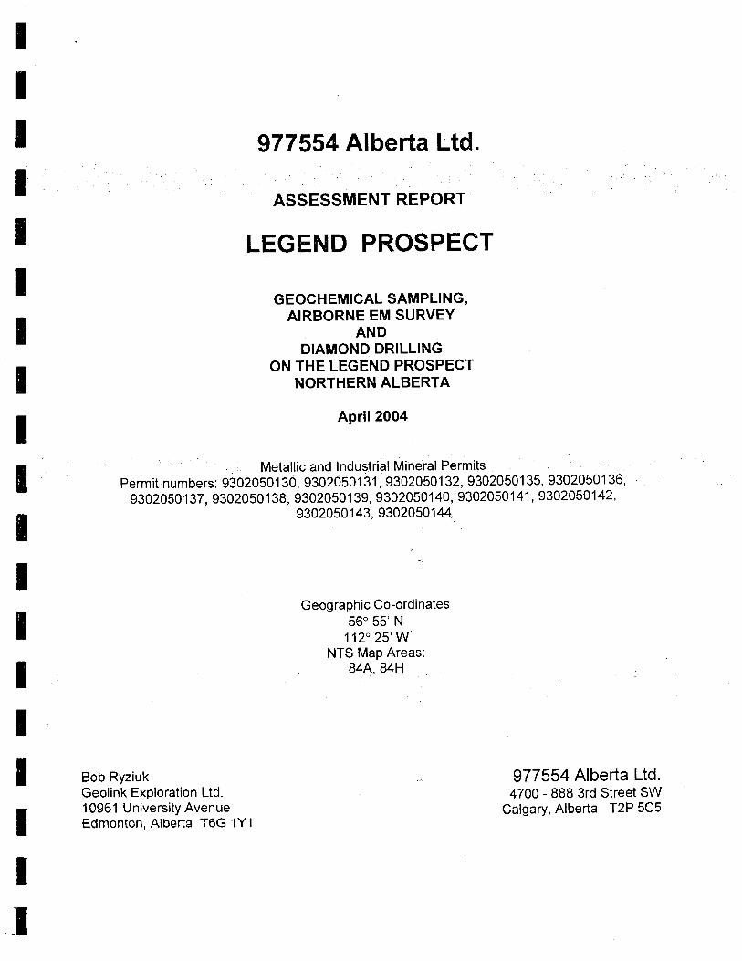
Figure 2 - Geology and Claim Location ........................................................ 4
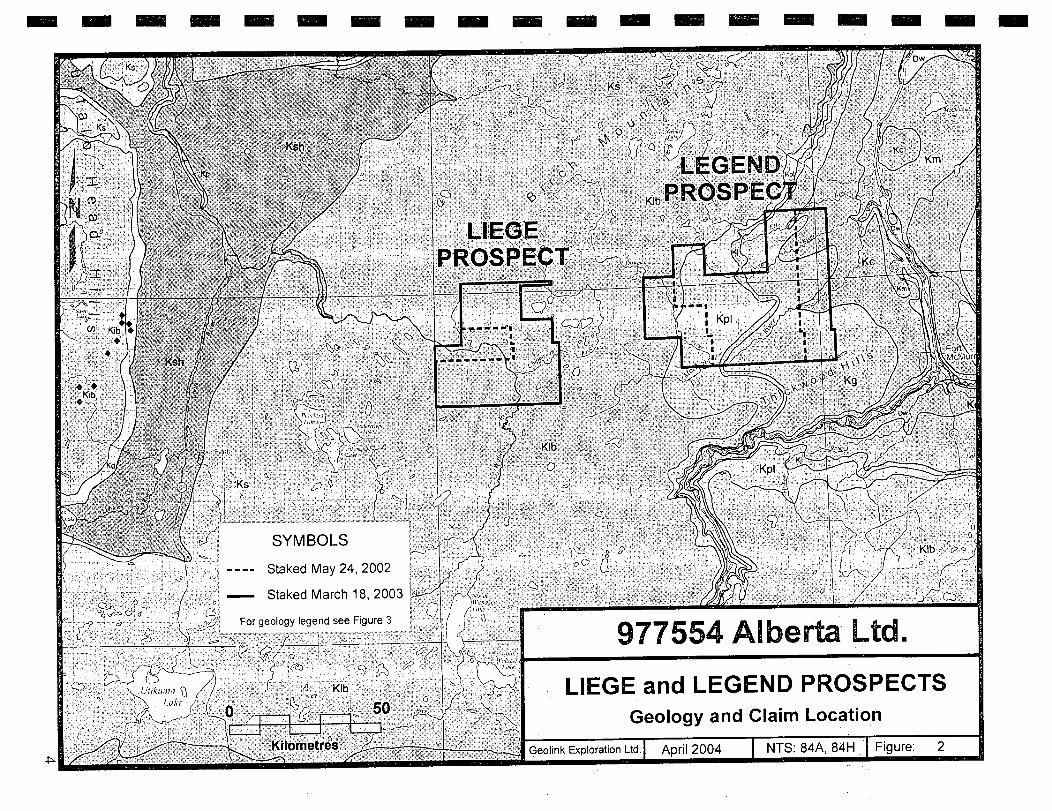
Figure 3 - Geology Legend 5
Work Performed and Results 6
Conclusions and Recommendations ........................................................7
Table 2 - Summary of Indicator Sampling ........................................................8
Table 3 - Ashton DIM Sampling 9
Appendix 1 - Summary Geological and Geophysical Report ........................................................at end
Appendix 2 - Indicator Sampling Results ........................................................at end
Appendix 3 - Airborne Geophysics ........................................................at end
Appendix 4 - Diamond Drilling at end
Appendix 5 - Statement of Expenditures ........................................................at end
Figure 4 - Compilation Map map
Figure 5 - Claims to Keep, Assessment Filed .........................................................map
CD ROM of Fugro Airborne Geophysics .........................................................map

LEGEND PROSPECT
Exploration Summary
Kimberlite exploration on the Legend Prospect by 977554 Alberta Ltd.,included indicator mineral sampling, airborne geophysics and diamond drilling. A total of 4 sites were sampled for indicators, 53.8 kilometres of Heli Mag/EM were flown and 4 diamond drill holes concluded without a kimberlite discovery.
Location and Access
The Legend Prospect is located in northern Alberta 55 kilometres northwest of the town of Fort McMurray (Figure 1). Winter access to the center of the property is along oil industry roads from Fort McMurray. Summer access is by helicopter or Argo.
Claim Information
Land acquisition began on May 24, 2002 when 13 permits totaling 119,808ha were recorded. On March 18, 2003 an additional 9 permits totaling 82,944ha were recorded.
I The Legend Prospect consists of 22 metallic and industrial mineral permits totaling 202,752ha. A complete list of mineral permits is included in Table 1 and is shown on Figure 2.
Exploration History
Ashton Mining of Canada Ltd. began work in the area in 1996 as part of their regional Buffalo Hills Exploration Program. Airborne magnetic surveys and indicator mineral sampling were two of the exploration techniques employed. Assessment Reports filed by Ashton document the results.
977554 Alberta Ltd. Acquired the claims in 2002 and 2003 based on information it had concerning the possibility of kimberlite pipes in the area. Figure 2 shows the regional geology and Figure 3 is the geological legend (Alberta Geological Survey).
I I
I I I I I I I I I I
I I I I I
1 1

TON
Lloyd Camro
Drumheller
(J,
C)
inster
rooks
MI
bridge . .
Milk River.
MONTANA.:. :.. Figure 1
I I I I a
977554 ALBI Steen River
c.
Hig Level
Fort: erm lion -
RTA,., DU
1 Legend Prospect
Manning. ( \Fort . . ....
McM
urray ;.• Red Earth
Peace Creek
River
• . .. I • . . . Grand High Slave Lake
Prairie Prairie
Ahat
urt. ........: S
I nde Cache
. •. Edson into
sper
Fed
anif A
LOCATION MAP Legend Prospect
April 2004
I I I I I I I I I I I I I I
2

I I
Table 1 - Claim Information
LEGEND PROSPECT Location
Permit Number Meridian-Range-Township Area (ha) Effective Date
Section
9302050130 4-14-90:1-36 9,216 24-May-02
9302050131 4-15-90:1-36 9,216 24-May-02
9302050132 4-16-90:1-36 9,216 24-May-02
4-14-91: 1-3 10-15 22-27 34-36
9302050135 4-14-92: 1-3 10-15 22-27 34-36
9,216 24-May-02
9302050136 ' '
9,216 24-May-02
9302050137 iii 9,216 24-May-02
9302050138 9,216 24-May-02
9302050139 9,216 24-May-02
9302050140 9,216 24-May-02
9302050141 4-17-92: 1-36 9,216 24-May-02
9302050142 ' ' 9,216 24-May-02
21 28-33 9302050143
-- I: i: 9 ,216 24-May-02
9302050144 4-17-93: 1-36 9,216 24-May-02
13 Permits 119,808
9303031176 4-13-90: 1-36 9,216 18-Mar-03
9303031177 4-13-91: 1-36 9,216 18-Mar-03
9303031178 4-13-92: 1-36 9,216 18-Mar-03
9303031179 4-13-93: 1-36 9,216 18-Mar-03
9303031180 4-13-94: 1-36 9,216 18-Mar-03
9303031181 4-17-90: 1-36 9,216 18-Mar-03
9303031182 4-17-91: 1-36 9,216 18-Mar-03
9303031183 4-18-91: 1-36 9,216 18-Mar-03
9303031184 4-18-92: 1-36 9,216 18-Mar-03
9 Permits 82,944
22 Permits TOTAL PERMITS 202,752 I
I
3
I I I I I I I I I I I I I I I 1
- - - - - - - m - - - - - - - -

- — — — — — — — — — —. — — —
Geological Map of A Legend AGS Alberta Energy and Utilities Board Alberta G.olegrnal Satoey
[Kp PUSKWASIYP.0 R)AMAI10N: dark grey toeerllterOUe drale, Sty K a-par part:
OADHEAR'TFORMAIiOtL fine,grahedq awiesaiddatartkrt0iiO otodo .ar.dGto(rb and mudatale; math.
fl CASKAPAU FORMATION: dark 9110111111* ttkn oantrdionary raratt.re bedS; KB art thaddod low parr Winit gr ad an ana. a. da and S b de Ce
terrrornne , annk , onmiirtrreie,iearmn ,
Kd - DUNVEGAN FORMATION: grey, hnargrwned, feldapethuc .andarone wCtr hard - c.1uareaie beat; isminded aLert... and glen oily elsie, Slide to marine
UPPER AND LOWER CRETACEOUS
-- Tn OI4AFThSSUAY FOAMA11OPIi dark grey hel-gasie be.rurg ehde, airy in a-par part;
aoerou thnlee and b dad at a b ory S barter t partings; lade.
arthibw airy and randy Krab. mar.10
ri "=====.=
Kg - SMOKY OROUP: dark grey eh.ie and'ettry alicia. rraidule• and ttrkr bed. 04
- rk taine and 601.1. Head Kill.; marine
[] DIJNVEGAN FORMATION: grey, fine-grained, teidepathio rani with hard odoa,rea,a berM; terminated sitSona and grey airy grate: Slr.n to rrranrre
UPPER AND LOWER CRETACEOUS
SHAFTEBBURY FORMATION: dark grey tab-scale beating abate, idly in upper pen arail dulas andth bed.ci .—riflonarry or be wilt pealing lower peat with thin Shy and bandy litteruel,, rrr.rLie
CRETACEOUS
UPPER AND LOWER CRETACEOUS
- KIb LADiCHE FORMAtiON: dark grey abate and asry shale; itordone parings end nanaalidis; airytlel-arale bearing beds In 0.0. pea; marine
LOWER CRETACEOUS LOWER CRETACEOUS
LOWER CRETACEOUS r [ipl POLICAN FORMATiON: trn.-graned qu.rtaoee .endaord. city and yauconlrro in
PEUCANFORMAT1ON. t:n..gr.eredqu.rtdO,eewiddone city and d.ucoretc Or
1—arpan marine
PEACE RIVER FORMATION: rrsrbgray Imiltyan I fin-linnartdel d to - - city IderbeSi in loser pad (Ha IbW); finaaed anadawie iwiddere - - -
(C dad tteter) drorHlrr000rrrpl [] JOLIFOUFOAMAT1ON dark g yto0elit an anal dy teth ira-parp P.M. [I[i] JOUFOUFORMAI1ON dell gr.ytUs IC dad ly arbwiNsrrtap part
Side. aanddoire :00.0. pad 04 map knit may be egagaleid to n Meneler L marine :.
marine
a-,rmo04 aradb,r 04 undanlyng gpkut SnOt Formariwi lL Suet Fatyatiwi ea-iwaiwill in NW Shea. arbwiU.oe . - - . r' K -
ORANO RAPIDS FORMATION: tIne-gramed guaneoce and tekMpadrio aarddoere. - i laminated eiitdooe and cIty Are,; SIr coal bed,: elnoesine complen
LOON RIVEAFORUATiON: darkgrey,teeslietans,htyahdeandtammndea ''KI'- LOON RIVER FORMATION: dark grey, boeliterwie. city.hai. and laminated
I roAd an h bertaol noet ary arear m I on thu rid to t*d r orrcr 00 yl art - - -,,- - - - - cLEARwA'rnle FORMATION: dark grey, tog,lLerguS idly ariSe, la,nrlrrared Slidorle
dtdril inodoirmnyoarrd tan cone gandaion (WetS kewMe.rtbeelno
b rari
Kb OASALCRETACEOUS Cal an q arid (it W ad 0044.1 N*ti0ni Par I j Km MOMURRAY FORMATION: S at baddad a- ira read S an and dt000 be
orlgrnunoertdn .,- impnegrnated. grey airy shale rnterbe In a-pa part, narrirarrrro to denaio
Ui
CREDITS Geological cartpllaVal by rlle N. Hamilton, Monica C Pnce and C.WilIem Langenberg
GIS (Arc/lntOl map compilation by Monica C. Price GIS consultation by Dennis K. Chao Cartraphy Canvas) by Dan Magee Inset map arid cross section compilation assistance by Matthias Grcthy
External rennewby Robert Green, Consulting Gedogist
Sources 01 Data The map is medilied trom the Gyolicat Map 01 Ojbena, by R. Green, 1972, Ojbena GedcicaI Survey, Alberta
Research Council. Re
Is since 1972 have incorporated new mapping data from work by the 7lbena Geclogicat
Survey and the Geological Survey of Canada, and by the Canadian Satiety of Petrdeurrr Geologists through the ccntrrbutiner OF its membership to the Geological Alas OF the Western Canada Sedimentary Basin
Unpublished gedogical data on Paleatene and Upper Cretaceous tolrnatlorl boundaries wnte contributed by
1. JerZykietntcZ, Consulting Gedc5ist. lntomration tou.nrd enhanced mapping 01 the Sccltard Formation boundaries was provided by the Mine Development
Group, Alberta Energy and Udlities Board
The tectonic inset maps aie based on information from vancojo published sources Precambnan Basement, pnnnarily GSC reports, Phanerozoc, pnmanly the Gedppical Adds of the Western Canada Sedimentary Basin GlaclotectcfliC terrains are Iran unpublished inFormation supplied by M.M. Fenton, Alberta Geological Survey.
The digital base map was supplied by Alberta Environmental Protection
Any additional gedical Information known to the user or suggestions for enhancement of the map would be weiccenred by lie Alberta Geological Survey. The CIS digital tile is uated as new information is cbtained and
is available on request.
Recommended citation Harniltoel, WN., Price, M.O.and Langenbetg. C.W. (compilersI, 1999; Geological Map at Alberta, Alberta Geological Si elbena Energy and Utilities Board, Map No, 236, scale 1:1,O,CCO.
977554 Alberta Ltd.
LIEGE and LEGEND PROSPECTS
Geology Legend
Geolink Exploration Ltd.I April 2004 I 84A, 84H I Figure: 3

I
Work Performed and Results
I Summary Geological and Geophysical Report - In April, 2003 a qualifying report (NI 43-101) was written by OreQuest Consultants Ltd. of Vancouver, B.C. The complete report is included in Appendix 1
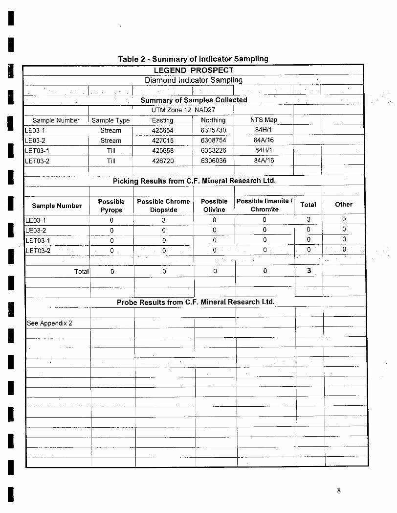
I Indicator Sampling - Only 4 samples were collected on the property. Indicator sample sites and results are listed in Table 2 and shown on Figure 4. The complete report from C.F. Mineral Research Ltd. is in Appendix 2. Ashton
I
Assessment Report #20010007 reported 109 samples west of the Legend area. A summary of the sampling is listed in Table 3.
Airborne Geophysics - Fugro Airborne Surveys Corp. of Calgary, Alberta was contracted to fly a Hell Mag/EM system over 4 targets on the Legend Prospect, Targets 1, 3, 4 and 5 as shown on Figure 4. A total of 53.8 line kilometres of "Resolve" Hell Mag/EM were flown. Surveys over Targets 1, 4 and 5 had interesting signatures and drill holes were spotted to test the anomalies. The complete geophysical report is in Appendix 3.
Diamond Drilling - Four holes were drilled between February 20th and March 5th 2004. The holes were located to test seismic and airborne EM anomalies consistent with kimberlite signatures. The drill hole locations are listed below and are shown on Figure 4.
DIAMOND DRILL HOLE LOCATIONS
I I I
Hole Number
D D H 04-1
DDHO4-2
DDHO4-3
DDHO4-4
UTM Zone 12 NAD27
Easting Northing
426611 6306095
415761 6308836
427151 6306044
425561 6332776
NTS Map Total Depth (metres)
84A/16 73.2
84A/16 93.3
84A/16 91.4
84H/1 30.5
All holes were accessed by existing cut line cleared of snow. Hole DDH04-1 was located on a cut line. Holes DDH04-2 and DDH04-3 required small (15 by 15 metre) clearings in swamp spruce. Hole DDH04-4 required 70 metres of new road to be built through 2" to 12" poplar trees.
None of the holes encountered kimberlite and no core was recovered. Each hole was drilled with a tn-cone bit and drill cuttings were observed but not sampled. All holes bottomed in what appeared to be unconsolidated glacial till.
Figure 4 summarizes the indicator sampling, geophysics and diamond drilling.
I I I I I
I I I I I
6

I I I I I I I I
Conclusions and Recommendations
The four diamond drill holes spotted to test geophysical anomalies did not result in the discovery of kimberlite or even bedrock The EM anomalies must therefore be related to the unexpectedly thick overburden.
More work should be done on the prospect such as: o Detailed stream and till diamond indicator sampling. • Fixed wing airborne EM survey (Geotem or Megatem - deep penetrating
techniques).
I I I I I I I I I I I 7
I I
Table 2 - Summary of Indicator Sampling
LEGEND PROSPECT Diamond Indicator Sampling
Summary of Samples Collected UTM Zone 12 NAD27
Sample Number Sample Type Easting Northing NTS Map
LE03-1 Stream 425654 6325730 84H/1
LE03-2 Stream 427015 6308754 84N16
LET03-1 Till 425658 6333226 84H/1
LET03-2 Till 426720 6306036 84N16
Picking Results from C.F. Mineral Research Ltd.
Possible Possible Chrome Possible Possible Ilmenite I Sample Number Total Other
Pyrope Diopside Olivine Chromite
LE03-1 0 3 0 0 3 0
LE03-2 0 0 0 0 0 0
LET03-1 0 0 0 0 0 0
LET03-2 0 0 0 0 0 0
Total 0 3 0 0 3
Probe Results from C.F. Mineral Research Ltd.
See Appendix 2
I I I I I I
I I I I I I I I I I
I
8

I I
Table 3 - Ashton Mining of Canada Diamond Indicator Sampling
LIEGE and LEGEND PROSPECTS
Diamond Indicator Sampling by Ashton Mining of Canada Ltd.
Ashton Assessment Report# 20010007 7 April 25, 2001
Ashton Sample UTM NAD 27 UTM NAD 27
Indicators Total Indicators Zone Map Sheet Number East North
AL04-0105 670657 6277703 ipi 1 liv - 8413/9
AL04-0108 682915 6279867 ipp 1 liv 841319
AL04-0111 674862 6282433 ipi 1 11V 841319
AL04-0112 680648 6287875 lep 1 11V 8413/9
AL04-0118 320896 6290264 ic 1 12V 84A/12
AL04-0120 349910 6332197 ipp 1 12V 841-1/3
AL04-0136 400085 6298147 6pp;1ep;1pi 8 12V 84A/15
AL04-0137 395848 6301651 1pp;5p1 6 12\/ 84A/15
AL04-0138 332800 6304989 2pp;2c;l pi; lko 6 12v 84A/13 -
AL04-0139 328290 6303986 3pp;4ep;2c;2pi ii 12V 84A/13
AL04-0140 336030 6309000 1pp;3ep;3c;22p1 29 12v 84A/13
AL04-0141 324154 6317097 iep;lc;2pi 4 12\/ 84A/13
AL04-0143 682365 6316592 2p1 2 liv 8413/16
AL04 0144 665278 6328261 ippipi 2 liv 84G11
AL04-0150 362607 6301824 ipp 1 12v 84A/14
AL04-0154 330700 6319962 iko 1 12v 84A/13
AL04-0157 334960 6315050 3pi 3 12v 84A/13
AL04-0177 673815 6337200 ic 1 iiv 84G/1
AL04-0178 345980 6314403 2c 2 iiv - 84D/13
AL04-0179 345970 6310500 ipi 1 iiv 84D/13
AL04-0181 368161 6327305 lpp 1 12v 841-1/3
AL04-0184 338700 6307790 iko 1 12v 84A/13
AL04-0189 342185 6298320 3ko 3 12\/ 84A/13
AL04-0194 330000 6292920 1 pp 1 12v 84A/13
AL04-0205 676432 6330857 ic 1 liv 84G/1
AL04-0206 670566 6329048 leo 1 iiv 84G/1
AL04-0212 677740 6314730 ipi 1 liv 8413/16
27Samples Total 92 Indicators
pp PeridoticPyrope
eg EclogeticPyrope
cd ChromeDiopside
cd Chromite
pi Picroilmenite
ko Kimbertitic Olivine
Note: Only anomalous samples listed here. See Assessment report #20010007 for complete results for all 109 samples.
I
9
I
I I I I I I I I I I I I I I
ILL

I I
I 1 I
977554 Alberta Ltd. I
I ASSESSMENT REPORT
I LEGEND PROSPECT
I I I I I I I I I I I
APPENDIX I Summary Geological and Geophysical Report
I Bob Ryziuk
977554 Alberta Ltd. Geolink Exploration Ltd.
Edmonton, Alberta T6G 1Y1 10961 University Avenue Calgary, Alberta T2P 5C5
4700 - 888 3rd Street SW
I

I I I I I I I I I I I I I I I I I I I
SUMMARY GEOLOGICAL AND GEOPHYSICAL REPORT
on the
LIEGE and LEGEND PROPERTIES
EAST PEACE DISTRICT ALBERTA NTS 84A
for
977554 ALBERTA LTD.
George Cavey, P. Geo. J. L. LeBel, P. Eng.
OreQuest Consultants Ltd.
April 24, 2003
O

I I I I I I I I I I I I I I I I I I I
LIST OF APPENICES
Appendix I Metallic and Industrial Permit Schedule................................................................28
Figure 1 Figure 2 Figure 3a Figure 3b Figure 4
5
LIST OF FIGURES
Location Map ........ ........................................ ................ ................. .Following Page 6
Permit Location Map ................................................................Following Page 7
Regional Geology......................................................................Following Page 10
Structure and Tectonic Map......................................................Following Page 10 Anomaly Location Map .............................................................Following Page 15

I I
INTRODUCTION AND TERMS OF REFERENCE This report presents a summary geological and geophysical evaluation of two properties, the
Liege Property and the Legend property, located in East Peace District of North Central Alberta for 977554 Alberta Ltd. which is a wholly owned subsidiary of Paramount Resources Ltd. The subject property permits cover a portion of north-central Alberta (Figure 1). The report is done by independent Qualified Persons as required by the National Instrument 43-101, Standards of Disclosure for Mineral Properties, according to the format and content specified in Form 43-101 Fl, Technical Report. This report has been completed to comply with 977554 Alberta Ltd.'s "Preliminary Prospectus" filing requirements and has been prepared under the terms set out in NI 43- 101.
The information contained in this report comes from previous work done in the area as documented in reports listed in the References section of this report and information from the results of seismic reflection surveys conducted by Paramount Resources Ltd. for natural gas exploration. The material found in this technical report is an amalgamation of previous assessment reports, program updates, consultant reports, and corporate press releases available for review. There were no limitations put on the author in preparation of this report by Paramount or 977554 Alberta Ltd. The
author Cavey of this report is familiar with the subject matter covering the preceding and intervening years and the current publicly available body of data and has authored or co-authored numerous diamond reports since 1993 dedicated to Alberta Diamond Exploration including Pure Gold Minerals Inc. on its diamondiferous Buffalo Hills property the Buffalo Hills area. A complete list of the reports prepared in whole or in part by the author on behalf of OreQuest Consultants Ltd. can be found in the References section of this report under the sub-heading "OreQuest Reports Previously Prepared". Author LeBel did a three hour helicopter reconnoiter of the properties on April 16, 2003 which entailed an examination of the sites of seven geophysical anomalies and a brief ground examination at one site to fulfill the requirements of National Instrument 43-101.
The exploration merits of the properties are embodied in geophysical anomalies which have no physical manifestation. A ground examination of all the specific anomaly sites could prove fruitless because the area is largely blanketed by thick overburden which is likely to conceal the sources of the geophysical anomalies from view. There is no known mineralization on the properties to observe and very little on-site physical work to be verified, and the local details of the geology are immaterial in the genesis and emplacement of diamond mineralization.
DISCLAIMER Most of the information contained in this report comes from previous work done on the
properties by other parties obtained from the reports referenced, herein. The authors have not verified the historical work, but recognized exploration and mining companies, registered professionals and reputable contractors and service companies did the work. As a result, the authors have no reason to question the veracity of the results. OreQuest has prepared this report based upon information believed to be accurate at the time of completion, but which is not guaranteed. Paramount Resources Ltd. have provided a compilation on legal title of the properties.
I I I I I I I I I I
I I I I I

I I I 1 I I I I N I I I I I I 1 I I I
NORTHWEST TERRITORIES
'H High Level
LEGEND LIEGE PROPERTY
iI PROPERTY urray
Peace River
L7
rl I Grande
Prarie
Edmonton
Jasper
Camrose
K . Red Deer
O 50 100 km
50 miles Banff
ORE QUEST Calgffly
[
977554 ALBERTA LTD. J Figure 1 Medicine
Hat
LIEGE AND LEGEND PROPERTIES
PROJECT Lethbridge
LOCATION MAP Alberta
MAY 2003 XY3
41, ME I I
7
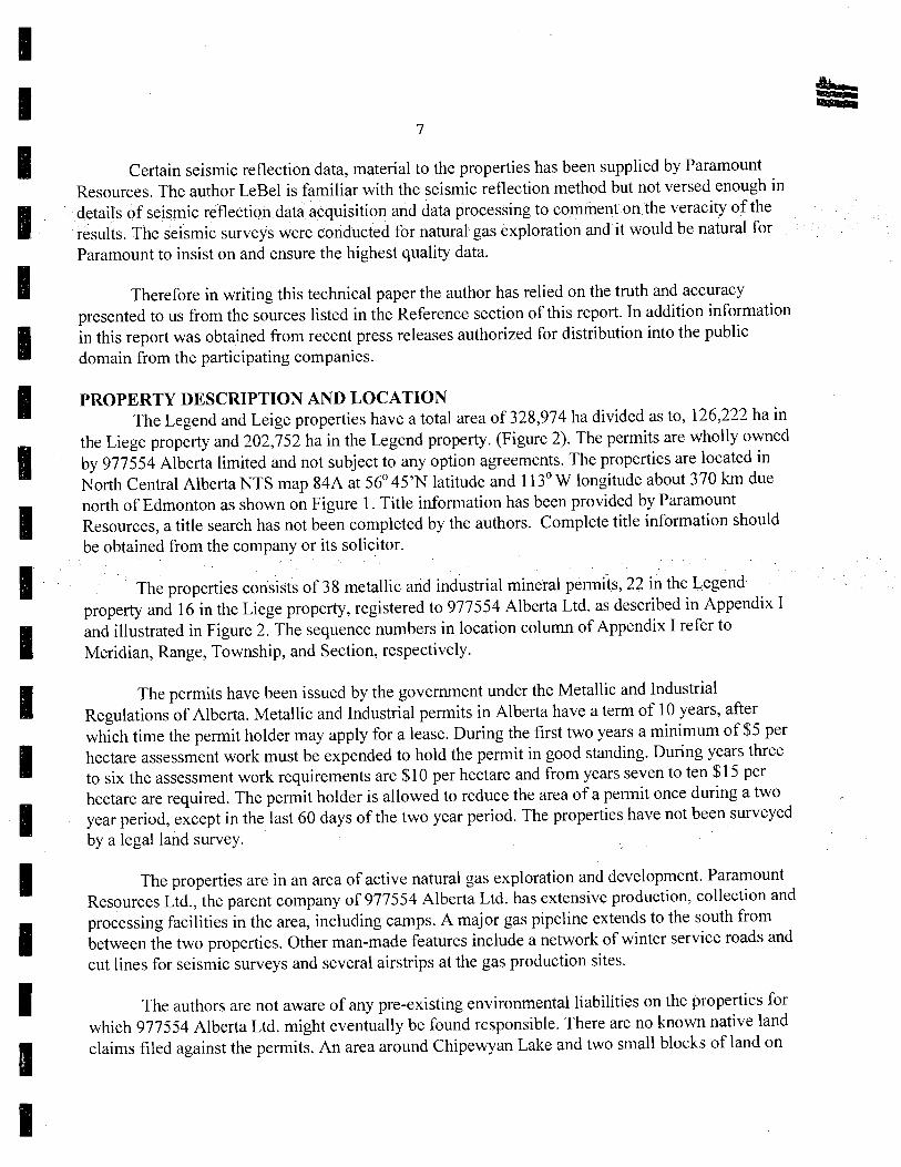
Certain seismic reflection data, material to the properties has been supplied by Paramount Resources. The author LeBel is familiar with the seismic reflection method but not versed enough in detailsof seismic reflection data acquisition and data processing to comment on the veracity of the results. The seismic surveys were conducted for natural gas exploration and it would be natural for Paramount to insist on and ensure the highest quality data.
Therefore in writing this technical paper the author has relied on the truth and accuracy presented to us from the sources listed in the Reference section of this report. In addition information in this report was obtained from recent press releases authorized for distribution into the public domain from the participating companies.
I PROPERTY DESCRIPTION AND LOCATION The Legend and Leige properties have a total area of 328,974 ha divided as to, 126,222 ha in
I the Liege property and 202,752 ha in the Legend property. (Figure 2). The permits are wholly owned by 977554 Alberta limited and not subject to any option agreements. The properties are located in North Central Alberta NTS map 84A at 56 ° 45'N latitude and 113 ° W longitude about 370 km due
I north of Edmonton as shown on Figure 1. Title information has been provided by Paramount Resources, a title search has not been completed by the authors. Complete title information should be obtained from the company or its solicitor.
The properties consists of 38 metallic and industrial mineral permits, 22 in the Legend property and 16 in the Liege property, registered to 977554 Alberta Ltd. as described in Appendix I
I and illustrated in Figure 2. The sequence numbers in location column of Appendix I refer to Meridian, Range, Township, and Section, respectively.
Thepermits have been issued by the government under the Metallic and Industrial Regulations of Alberta. Metallic and Industrial permits in Alberta have a term of 10 years, after which time the permit holder may apply for a lease. During the first two years a minimum of $5 per
hectare assessment work must be expended to hold the permit in good standing. During years three to six the assessment work requirements are $10 per hectare and from years seven to ten $15 per hectare are required. The permit holder is allowed to reduce the area of a permit once during a two year period, except in the last 60 days of the two year period. The properties have not been surveyed by a legal land survey.
The properties are in an area of active natural gas exploration and development. Paramount Resources Ltd., the parent company of 977554 Alberta Ltd. has extensive production, collection and processing facilities in the area, including camps. A major gas pipeline extends to the south from between the two properties. Other man-made features include a network of winter service roads and cut lines for seismic surveys and several airstrips at the gas production sites.
I The authors are not aware of any pre-existing environmental liabilities on the properties for which 977554 Alberta Ltd. might eventually be found responsible. There are no known native land claims filed against the permits. An area around Chipewyan Lake and two small blocks of land on
1

— — — — — — — — : — — —
OREQUEST - " f-i-'-f-;J N{
977554 ALBERTA LTD : * HYT
0T H BA
Figure
I ii tki:t:t: LIEGE AND LEGEND PROPERTIES TT TlfE
PERMIT /\
, . LOCATION MAP I I iL L1_ E1,Id4i_
Alberta
MAY 2003 XY3J
25T r
: : )(•. 't L
+ -- -t 7___
#7_ T J c 1Ti1 j I y Tr
( 94 — k / LEGEND k ' 9303031180 MT
J I ; PROSPECT " I ::t
- ;t
93 o L LIEGE /
9302050144 93O379 j \
PROSPECT SE LINE
93O2O5O14O
9303931196930303119793O3031198 930303118493020 014 ------------- t93030311 8
9302050139
--+- 4 + + T 93Q3U3119593O3O31194a !9 i. 9302050138 i
- 9303031183 9303031182 -------. 9303031177 930200134 4 90205013393 30311q3 93020137 4 t
. ' 930050134 1 133 134 133 )J
930031192 93 303118 33 O5O13 9302050131 90250130 9303031176 / r 93030319 9303031190 9303031191
__
89gl
3o1o31183a3O31l8693NPll8Tt930331185
d 23RD BASE LiNE
_
88'' L J I I IT: ; j L

I I I
8
the Liege property are withdrawn from 'staking'. Neither of these small blocks lies close to principal areas of interest that will be discussed in this report.
An exploration permit is required from the Alberta Department of Environment as a
prerequisite to drilling. 977554 Alberta Ltd. intends to require the necessary permits as needed. Other companies have successfully operated diamond exploration programs in the area and no difficulty in obtaining the necessary permits is anticipated.
I ACCESSIBILITY, CLIMATE, LOCAL RESOURCES, INFRASTRUCTURE AND PHYSIOGRAPHY
The Legend and Liege properties are located approximately 370 kilometres north of the city of Edmonton in north-central Alberta. Fort McMurray connected to Edmonton via paved highway and is serviced by several daily commercial flights from Edmonton and Calgary. Most supplies to
I
support exploration and development can also be obtained in Fort McMurray which is the main center for the development of the Alberta tar sands projects.
The area is readily accessible by several modes. The are several airstrips in the area maintained at natural gas production facilities capable of handling large fixed wing aircraft. One of these airstrips is located at Chipewyan Lake on the Liege property. The Alpac Paper Company maintains an all season haulage road in the area that comes in from Athabasca to the south The natural gas production facilities are also serviced by a winter road which comes into the area form Fort McMurray to the east. Fort McMurray is also the permanent base of three helicopter companies. Access in and around the properties for exploration purposes is available by helicopter or 4-wheel drive vehicle/all terrain vehicle/snowmobiles along winter gas field service roads and numerous
seismic lines or on foot.
There are no permanent human residents in the area. The closest community is Fort McMurray which is 140 km west of the center of the Liege property and 60 km west of the center of the Legend property. There are several camps at gas plants in the area which are manned by maintenance personnel on a 2 week rotation where field crews could be based.
I The topography is a flat-lying plateau with a few shallow lakes, numerous swamps and a few slow moving meandering rivers and creeks. Many of the creeks are dammed by beaver dams. The
I average elevation is 500 in to 550 in a.s.l. What little relief there is comes in the form of low broad hills a maximum of 50 in high and river valleys incised as much as tens of meters. The area is at the height of land between the drainage basins of the Peace and Athabaska Rivers. Drainage in the Liege
I property is to the north to the Peace River and to the east in the Legend property to the Athabasca River. The vegetation is boreal forest, a mix of 25% open swamp, 25% swamp with scrub conifers and 50% coniferous-deciduous forests of spruce and poplar trees. The poplar stands prefer the better drained areas and the spruce trees prefer the wetter ground.
The physiography of the area is a function of the pre-glacial fluvial processes. Rivers deposited gravels and sands onto sedimentary rocks that in turn were uplifted and further eroded into
I I
I I I I I
I
4* ma- I I I
I
9
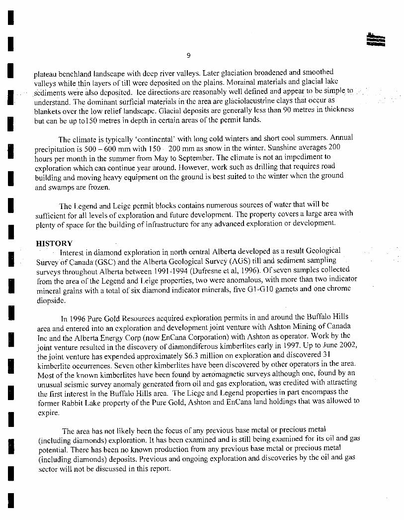
plateau benchland landscape with deep river valleys. Later glaciation broadened and smoothed valleys while thin layers of till were deposited on the plains. Morainal materials and glacial lake sediments were also deposited Ice directions are reasonably well defined and appear to be simple to understand. The dominant surficial materials in the area are glaciolacustrine clays that occur as blankets over the low relief landscape. Glacial deposits are generally less than 90 metres in thickness but can be up to 150 metres in depth in certain areas of the permit lands.
The climate is typically 'continental' with long cold winters and short cool summers. Annual
I precipitation is 500 - 600 mm with 150 - 200 mm as snow in the winter. Sunshine averages 200 hours per month in the summer from May to September. The climate is not an impediment to exploration which can continue year around. However, work such as drilling that requires roaa building and moving heavy equipment on the ground is best suited to the winter when the ground and swamps are frozen.
The Legend and Leige permit blocks contains numerous sources of water that will be sufficient for all levels of exploration and future development. The property covers a large area with plenty of space for the building of infrastructure for any advanced exploration or development.
HISTORY
I Interest in diamond exploration in north central Alberta developed as a result Geological Survey of Canada (GSC) and the Alberta Geological Survey (AGS) till and sediment sampling surveys throughout Alberta between 1991-1994 (Dufresne et al, 1996). Of seven samples collected
I
from the area of the Legend and Leige properties, two were anomalous, with more than two indicator mineral grains with a total of six diamond indicator minerals, five G -G 10 garnets and one chrome diopside.
In 1996 Pure Gold Resources acquired exploration permits in and around the Buffalo Hills area and entered into an exploration and development joint venture with Ashton Mining of Canada Inc and the Alberta Energy Corp (now EnCana Corporation) with Ashton as operator. Work by the joint venture resulted in the discovery of diamondiferous kimberlites early in 1997. Up to June 2002, the joint venture has expended approximately $6.3 million on exploration and discovered 31 kimberlite occurrences. Seven other kimberlites have been discovered by other operators in the area. Most of the known kimberlites have been found by aeromagnetic surveys although one, found by an unusual seismic survey anomaly generated from oil and gas exploration, was credited with attracting the first interest in the Buffalo Hills area. The Liege and Legend properties in part encompass the former Rabbit Lake property of the Pure Gold, Ashton and EnCana land holdings that was allowed to expire.
The area has not likely been the focus of any previous base metal or precious metal (including diamonds) exploration. It has been examined and is still being examined for its oil and gas potential. There has been no known production from any previous base metal or precious metal (including diamonds) deposits. Previous and ongoing exploration and discoveries by the oil and gas sector will not be discussed in this report.
I I I
I I I I I I I I
I I I I I I I I
10
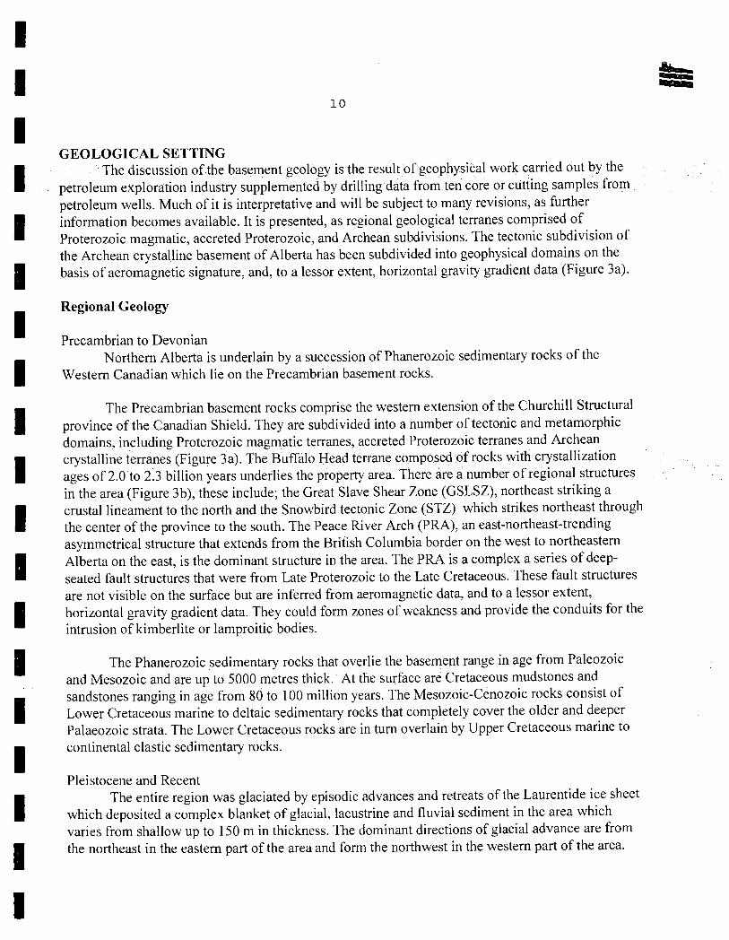
GEOLOGICAL SETTING The discussion of the basement geology is the result of geophysical work carried out by the
petroleum exploration industry supplemented by drilling data from ten core or cutting samples from petroleum wells. Much of it is interpretative and will be subject to many revisions, as further information becomes available. It is presented, as regional geological terranes comprised of Proterozoic magmatic, accreted Proterozoic, and Archean subdivisions. The tectonic subdivision of the Archean crystalline basement of Alberta has been subdivided into geophysical domains on the basis of aeromagnetic signature, and, to a lessor extent, horizontal gravity gradient data (Figure 3a).
Regional Geology
Precambrian to Devonian Northern Alberta is underlain by a succession of Phanerozoic sedimentary rocks of the
Western Canadian which lie on the Precambrian basement rocks.
IThe Precambrian basement rocks comprise the western extension of the Churchill Structural
province of the Canadian Shield. They are subdivided into a number of tectonic and metamorphic domains, including Proterozoic magmatic terranes, accreted Proterozoic terranes and Archean
I crystalline terranes (Figure 3a). The Buffalo Head terrane composed of rocks with crystallization ages Of 2.0 to 2.3 billion years underlies the property area. There are a number of regional structures in the area (Figure 3b), these include; the Great Slave Shear Zone (GSLSZ), northeast striking a
I crustal lineament to the north and the Snowbird tectonic Zone (STZ) which strikes northeast through the center of the province to the south. The Peace River Arch (PRA), an east-northeast-trending asymmetrical structure that extends from the British Columbia border on the west to northeastern
I Alberta on the east, is the dominant structure in the area. The PRA is a complex a series of deep- seated fault structures that were from Late Proterozoic to the Late Cretaceous. These fault structures are not visible on the surface but are inferred from aeromagnetic data, and to a lessor extent,
I horizontal gravity gradient data. They could form zones of weakness and provide the conduits for the intrusion of kimberlite or lamproitic bodies.
The Phanerozoic sedimentary rocks that overlie the basement range in age from Paleozoic and Mesozoic and are up to 5000 metres thick. At the surface are Cretaceous mudstones and sandstones ranging in age from 80 to 100 million years. The Mesozoic-Cenozoic rocks consist of Lower Cretaceous marine to deltaic sedimentary rocks that completely cover the older and deeper Palaeozoic strata. The Lower Cretaceous rocks are in turn overlain by Upper Cretaceous marine to continental elastic sedimentary rocks.
Pleistocene and Recent The entire region was glaciated by episodic advances and retreats of the Laurentide ice sheet
which deposited a complex blanket of glacial, lacustrine and fluvial sediment in the area which varies from shallow up to 150 in in thickness. The dominant directions of glacial advance are from the northeast in the eastern part of the area and form the northwest in the western part of the area.
I I I I I I

I NORTHWEST TERRITORIES - - -
/ Great Slave - Lake Zone I
N
ALBERTATERRANES H AUTOCHTHONOUS 7 BASEMENT /
AGE UNKNOWN
L Lacombe (supracrustal) High Level
R PROTEROZOIC MAGMATIC
Ta R Rimbeyl.80-1.86Ga 1/ B
LEGEND Ta Taltsori 1.95-1.97 Ga PROPERTY
K Ksotam1.90-1.99Ga I PROPERTY '•• ri ACCRETED PROTEROZOIC V Fort
McMurray
C Chinchaga 2.09-2.19 Ga I • \ H Hottah 1.85-1.92 Ga J Peace \
B Buffalo Head 1.99-2.28 Gal River
SnowbirdASHTON - BUFFALO HILLS Tectonic
W Wabamum 2.32 Ga j DIAMONDIFEROUS Zone
KIMBERLITES T Thorsby 1.92-2.38 Ga K
Grande ARCHEAN Prane
He Hearne 2.60-3.20 Ga (
R Rae 2.60-3.90 Ga R
S
Slave? 2.81 Ga
PHANEROZOIC COVER
[] Tertiary I Cretaceous
OpdahI/Burwsh Paleozoic
-.
Diamond -
o Diatreme Cluster - - - asper
O Lamproite/Kimberlite Occurrence
Diamondiferous Lamproite Occurrence . T
O Lamproite Indicators '—'Th '¼,- - /)
* Red $ Transported Diamonds '- R Deer
• Kimberlites -
Jack Pipe
Banff
ORE QUEST Calgary
0 Medicine Hat
0
0 ethbridge Legend Diamond
U
o 50 100 km tt Black Be I I Diamond
o 50 miles (after Can. J. Earth Sd. Vol 28, 1991)
I I
I I 1 I I I i
I I I I I I I I
Edmonton
Cantrose
He

(after Alberta Geological Survey Bulletin No. 63 1996)
NORTHWEST TERRITORIES
N
V \sDz
•\
• \ Salt High Level Dissolution
Partial Salt Boundary Dissolution Edge \ \
\.* •\
\ LIEGE
PROPERTY
Fort cvturra;\
GSLSZ Great Slave Lake Shear Zone
NAT Northern Alberta Trough <
PRA Peace River Arch
STZ Snowbird Tectonic Zone 1 TH Thorsby Low
WAA Western Alberta Arch
MLE Meadow Lake Escarpment
BIA Bow Island Arch .4 (extension of SGA)
SAR Southern Alberta Rift
CA Caroline Arch
AS Alberta Syncline
SDZ Salt Dissolution Zone
SGA Sweetgrass Arch (composite structure)
PRE Peace River EmbayrT
Eastern edge of the Rocky Mountain Fold
and Thrust Belt
Fault: right WE
Anticline
Syncline
Fold axis
Magnetic low
OREQ UE
I I I I I I I I I I I I I I I
I I I

1 I
:i1
I Local and Property Geology
I The formations present in the area are, the Upper Creteaceous, Smokey Group, the upper Cretaceous, Dunvegan Formation and the Middle Cretaceous, Shaftsberry Formation. The Smokey Group is composed of dark grey calcereous shale, marine foredeep deposits. The Dunvegan
I Formation is composed of marine conglomerate, sandstone, siltstone and shale. The Shaftsberry Formation is interpreted as a foredeep clastic wedge both marine and non-marine in origin composed of deltaic sandstone, fossiliferous silty shale and laminated siltstone. A detailed property geology map with the particular locations of these units is not presented herein, because the occurrence of kimberlites is governed by regional geology and tectonic forces, not the details of the local geology.
The physical properties of the host rocks have important implications concerning the effectiveness of the geophysical surveys commonly used to look for kimberlites and the occurrence of spurious anomalies from other non-kimberlite sources. Geophysical logging of numerous holes in the area by Ashton (Bauman, 1999a, 1999b) shows most of typical sedimentary formations are mildly magnetic with a magnetic susceptibility of less than 4X 1
0-3 SI units, but very uniform,
compared to kimberlite which typically exhibit magnetic susceptibility greater than 6X10 3 SI units.
The presence of a uniform background magnetic signature gives an advantage in reducing the number of spurious anomalies, compared to places like the Lac de Gras area of the Northwest Territories. In places, however, the overburden exhibits anomalous magnetic susceptibility and in at least one unsuccessful drill hole, namely DDHLL21-1 (Skelton and Willis, 200 1) the target anomaly was attributed to an overburden feature. Resistivity geophysical drill hole logging shows the sedimentaryformations to be conductive with variable resistivity as low as 5 ohm-m. Two kimberlite
intersections exhibited uniform resistivity of 50 ohm-m and 67 ohm-m, still on the low side for a crystalline rock but significantly higher than the background. These kimberlite bodies would be reflected in electromagnetic surveys as resistivity highs and indeed one of the kimberlites discovered by Ashton was found with an airborne electromagnetic survey.
There is also an appreciable contrast the density and acoustic impedance between the host rocks and kimberlite but gravity and seismic surveys are not typically applied in reconnaissance exploration for kimberlites because they are too expensive.
A problematic source of spurious geophysical anomalies in the area is the large number of natural gas production facilities. Although these man-made objects may produce magnetic and electromagnetic anomalies, the anomalies are usually 'spikes' which are limited in size compared to the response of a kimberlite that is 'smooth' and much larger. The location of natural gas production facilities also appear on government maps and for any questionable anomalies arising from man made sources the flight video may reveal the presence of man-made structures.
I DEPOSIT TYPES The Legend and Leige properties have potential for diamond mineralization.
I
I I I I
I

I I
tis 12
fli2mrndcz form in the crust and mantle it temneratures varying between 9000 C and 13000 C
and at pressures of 45 to 60kilobars, in two types of rocks; peridotites(P-type diamonds) and eclogites (E-type diamonds)
Diamond bearing peridotites are predominantly garnet-bearing harzburgite and more rarely lherzolite. Eclogitic kimberlite comprises mainly granular, red almandine-pyrope garnet and green omphacite pyroxene. Peridotite most commonly forms within the mantle. Eclogite is typically found in deep crustal metamorphic regions within continents. Eclogite forms by a solid state (metamorphic) transformation of previously existing rock - likely basalt through the subduction of crustal rocks.
Diamond is a high temperature and pressure polymorph of carbon. The carbon sources for diamonds are believed to be the original components of the primitive earth accumulated in the mantle, in the case of peridotite; and subducted upper crustal material transported to depth, in the case of eclogite.
Magmatic intrusions of kimberlite and lamproite volcanic rocks transport the diamonds to the earth's surface. These rocks originate at depths varying between 150 and 350 kilometres by partial melting of peridotitic or eclogitic material. This material rapidly ascends to the surface, rafting-up the diamondiferous xenoliths or xenocrysts A rate of ascent of 10 to 30 kilometres per hour (Kirkley et al, 1991) brings diamonds from a 150 kilometre storage depth to the surface in 5 to 15
hours without allowing for structural breakdown. The kimberlites and lamproites ascend along fractures that extend below the base of the craton in geologically stable areas. Within two to three kilometres of surface, the resultant pressure drop facilitates the expansion of gases creating violent explosions that increase the ascension velocity to several hundred kilometres per hour, until the intrusion erupts at the surface.
Kimberlites are volatile-rich potassic ultrabasic rocks with a distinctive inequigranular texture. Kimberlites are made up of material from three sources:
1. Mantle derived xenoliths (xenocrysts) of garnet lherzolite, harzburgite, eclogite and dunite; including diamond.
2. Megacrysts (1-20 cm), single crystals, of low chromium titanium pyrope, magnesian (picro)ilmenite, olivine, titanium poor chromite, chromium poor clinopyroxene, subcalcic to calcic diopside, enstatite, phiogopite and zircon;
3. Primary phase (groundmass) phenocrysts or microphenocrysts of olivine, phiogopite, spinel, ilmenite, perovskite, diopside, monticellite, apatite, calcite and serpentine. The early formed minerals are commonly altered by serpentinization and carbonatization.
Diamonds are also found in lamproites, which are potassium-rich mafic to ultramafic alkaline rocks and ultrapotassic leucite bearing (lamprophyric) rocks. According to Mitchell (1986) lamproites are characterized by the presence of one or more of the following minerals as major, minor or accessory phases; titanian (A1 203 poor) phlogopite, titanian tetraferriphlogopite, potassian
I I I U
I I I
I I I I I I I

I I I I I I I I I
13
titanian richterite, forsteritic olivine, diopside, sanidine, leucite, priderite, potassian zirconian silicate, wadeite, apatite, perovskite, magnesiochromite, magnesian titaniferous magnetite, j eppeite, armalcolite, shcherbakovite anatase, ilmenite and enstatite Alteration or other secondary phases include chlorite, silica, carbonate, zeolite, serpentine, barite and clay minerals. Lamproites may be distinguished from other potassic rocks and undersaturated alkaline rocks by the absence of nepheline, sodalite, hauyn, nosean, kalsilite, melilite, plagioclase, monticellite and melanite. The unique high temperature and pressure minerals peculiar to kimberlites and lamproites alone are often used as pathfinders in diamond exploration.
Primary diamond deposits are found within the earth's stable cratonic bells of Precambrian age (1.5 - 3.0 billion years), but commonly are at least of Archean age. These areas are believed to have been subjected to zones of uplift, are located near major faults, and dyke swarms. Within these areas, both diamondiferous and barren kimberlite and lamproite pipes occur. Kimberlites occur in clusters of three to fifty or more and can encompass a region stretching for 10's of kilometres commonly known as a field, in turn located in a geologically favourable environment called a kimberlite province. Within world renowned kimberlite provinces, in countries such as Russia, South Africa and the Northwest Territories of Canada diamondiferous pipes collectively occur over distances of hundreds of kilometres.
Kimberlite pipes vary in size from a few square metres to 217 hectares for the Ml kimberlite pipe in Botswana. The individual kimberlite pipes are generally elliptical to circular in shape and 'carrot' shaped in cross section, hence the term 'pipe'. A classic kimberlite pipe is comprised of a rootzone of dykes and sills, a tapered diatrerne zone, and a shallow crater facies at surface. The level of erosion of a pipe has an important impact on the economics of a diamondiferous kimberlite pipe. The middle, diatreme facies, makes up the greatest volume and has the highest and most homogenous diamond grade. The upper, crater facies has inconsistent grades and the deep root zones are irregular in both shape and grade.
In contrast to the kimberlites, lamproites studied to date are generally shaped like a 'champagne glass' rather than like a 'carrot'. A kimberlite shows two to three kilometres of vertical flaring while a lamproite will only show 100-500 metres of vertical flaring. Because of the higher volatility of kimberlites due to the increased CO 2 and H20 components, kimberlites tend to exhibit a
final explosive phase thus giving them their 'carrot' like appearance.
I The largest pipe in a kimberlite cluster is the one generally most likely to be economic, although there are two clusters of pipes in South Africa that contain more than one economic pipe. In
I the Northwest Territories, on the other hand, the economic pipes tend to be small, generally 2 ha or less in size. In addition, diamondiferous pipes within a kimberlite cluster do not appear to have a predictable distribution pattern, likely due to the explosive nature of their emplacement.
Most of the kimberlites in Northern Alberta are interpreted to be crater facies occurrences. They are described as vokaniclastic olivine-rich kimberlites with varying amounts of lapilli and
I I

I I I I I I I
14
xenoliths. A variety of indicator minerals are present; olivine is the dominant mineral followed by chromite, peridotitic and eclogitic pyrope garnets and rare picroilmenite.
Ashton Mining and their Buffalo Hills joint venture partners, Pure Gold and EnCana, have discovered 36 kimberlite pipes of which 24 are diamondiferous indicating that Buffalo Head Hills area is a new kimberlite province (Figure 3a).
MINERALIZATION The following is a general description of kimberlites found on the nearby Ashton/Pure
Gold/EnCana Buffalo Hills property. No diamond mineralization or kimberlite intrusions are known to occur on the Liege and Legend properties so this description only indicates the type of Occurrence that Paramount and 977554 Alberta Ltd. will seek on their two properties.
The detailed geology of one of the Ashton/Pure Gold/EnCana kimberlites is best described by Clements and Skelton (2001) as "Kimberlite outcrops were identified in four locations while in other areas, overburden up to 127 metres was intersected during drilling. Size estimates based on geophysical modeling range from one to 47 hectares. All but one of the kimberlites are classified as crater facies; most of them can be described as volcaniclastic olivine-rich kimberlites with varying amounts of lapilli and xenoliths. A variety of indicator minerals is present, olivine is the dominant mineral followed by chromite, peridotitic and eclogitic pyrope garnets and rare picroilmenite Kimberlites in the southern part of the province contain rare subcalcic (G10) garnets. Kimberlites located in the central and northern regions of the province contain a higher number of subcalcic garnets, some with exceptionally high chromium contents of up to 17.8 weight percent Cr 203."
A sample of kimberlite from Ashton BH225 was sent to Geospec Consultants of Australia for U-Pb perovskite age dating. The sample was collected at a depth of 75.3m and returned 206P/238U age
date of 85.1±1.2 Ma. No kimberlite intrusions are known to occur on the Liege and Legend properties so this description only indicates the possible age of the type of occurrence that Paramount and 977554 Alberta Ltd. will seek on their two properties.
EXPLORATION Neither 977554 Alberta Ltd. nor its parent company Paramount Resources Ltd. has carried
out any exploration on the properties directly for diamond mineralization. However, the properties cover areas on which Paramount has conducted exploration for natural gas, including seismic reflection surveys and drilling.
Seismic surveys are not a primary exploration tool in diamond exploration. However, in a sedimentary environment, a kimberlite diatreme intrudes through the sedimentary layering, it may be indicated by interruptions and/or disruptions in the seismic reflections from the normal sedimentary layering. Indeed, on the Buffalo Hills property of Ashton Mining of Canada just to the west seismic reflection surveys were instrumental in the identification of the K2, K4, K5, K6, K7, K32 and K92 kimberlites and aided in the determining the geometry and structure of the kimberlites (Skelton and Bursey, 1999a).
I I I I I I I I I g
I I
4* a. 3 0 I I
15
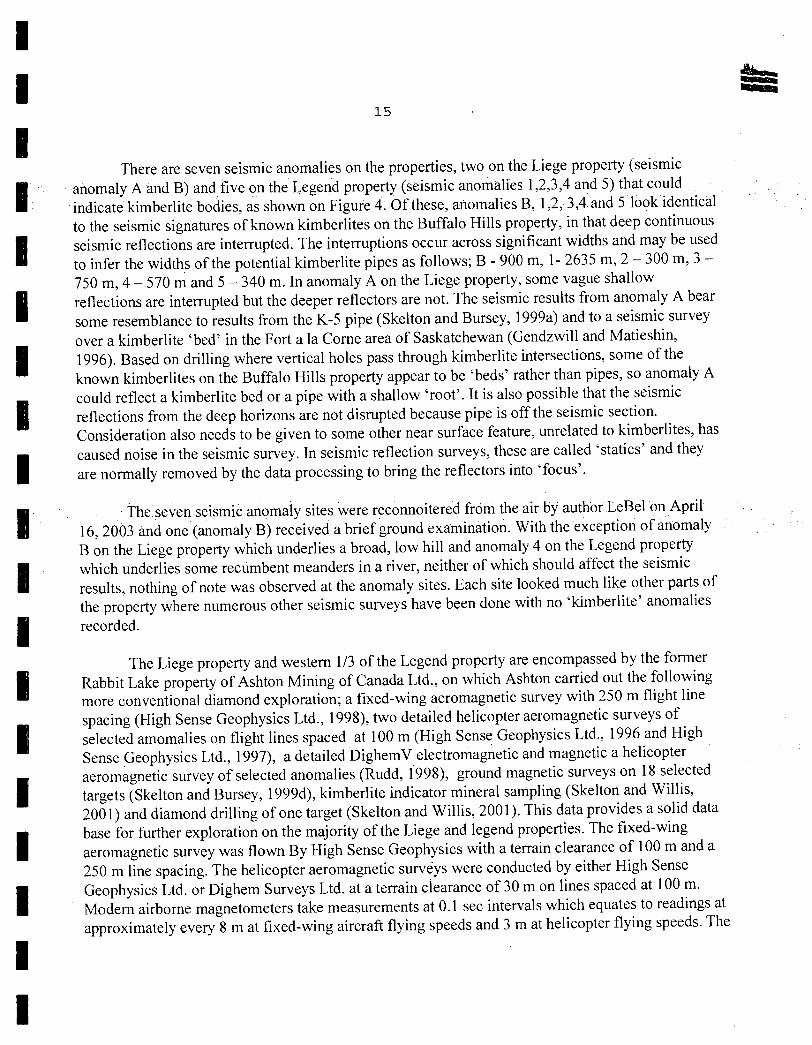
I There are seven seismic anomalies on the properties, two on the Liege property (seismic
I anomaly A and B) and five on the Legend property (seismic anomalies 1 2,3,4 and 5) that could indicate kimberlite bodies, as shown on Figure 4. Of these, anomalies B, 1,2, 3A and 5 look identical to the seismic signatures of known kimberlites on the Buffalo Hills property, in that deep continuous seismic reflections are interrupted. The interruptions occur across significant widths and may be used to infer the widths of the potential kimberlite pipes as follows; B - 900 m, 1- 2635 m, 2 - 300 m, 3 - 750 m, 4 - 570 in and 5 - 340 m. In anomaly A on the Liege property, some vague shallow
I reflections are interrupted but the deeper reflectors are not. The seismic results from anomaly A bear some resemblance to results from the K-5 pipe (Skelton and Bursey, 1999a) and to a seismic survey
I over a kimberlite 'bed' in the Fort a la Come area of Saskatchewan (Gendzwill and Matieshin, 1996). Based on drilling where vertical holes pass through kimberlite intersections, some of the known kimberlites on the Buffalo Hills property appear to be 'beds' rather than pipes, so anomaly A
I could reflect a kimberlite bed or a pipe with a shallow 'root'. It is also possible that the seismic reflections from the deep horizons are not disrupted because pipe is off the seismic section. Consideration also needs to be given to some other near surface feature, unrelated to kimberlites, has
rn caused noise in the seismic survey. In seismic reflection surveys, these are called 'statics' and they are normally removed by the data processing to bring the reflectors into locus'.
I The seven seismic anomaly sites were reconnoitered from the air by author LeBel on April 16, 2003 and one (anomaly B) received a brief ground examination. With the exception of anomaly B on the Liege property which underlies a broad, low hill and anomaly 4 on the Legend property
I which underlies some recumbent meanders in a river, neither of which should affect the seismic results, nothing of note was observed at the anomaly sites. Each site looked much like other parts of the property where numerous other seismic surveys have been done with no 'kimberlite' anomalies
I recorded.
The Liege property and western 1/3 of the Legend property are encompassed by the former Rabbit Lake property of Ashton Mining of Canada Ltd., on which Ashton carried out the following more conventional diamond exploration; a fixed-wing aeromagnetic survey with 250 m flight line
I spacing (High Sense Geophysics Ltd., 1998), two detailed helicopter aeromagnetic surveys of selected amomalies on flight lines spaced at 100 in (High Sense Geophysics Ltd., 1996 and High Sense Geophysics Ltd., 1997), a detailed DighemV electromagnetic and magnetic a helicopter
I aeromagnetic survey of selected anomalies (Rudd, 1998), ground magnetic surveys on 18 selected targets (Skelton and Bursey, 1999d), kimberlite indicator mineral sampling (Skelton and Willis, 200 1) and diamond drilling of one target (Skelton and Willis, 2001). This data provides a solid data
I base for further exploration on the majority of the Liege and legend properties. The fixed-wing aeromagnetic survey was flown By High Sense Geophysics with a terrain clearance of 100 in and a 250 m line spacing. The helicopter aeromagnetic surveys were conducted by either High Sense
I Geophysics Ltd. or Dighem Surveys Ltd. at a terrain clearance of 30 in on lines spaced at 100 m. Modern airborne magnetometers take measurements at 0.1 sec intervals which equates to readings at approximately every 8 in at fixed-wing aircraft flying speeds and 3 in at helicopter flying speeds. The
I I

- - - - - - - -
OREQUEST t LEGEND ' 7't * Seismic anomaly
_J_ ______ I •' I ____L_______L__-
977554 ALBERTA LTD. . KimberItes L3 ' \ 2$TH BASE! LINE
,
Fi re 4 .71 E Helimag detail F
. S Magnetic anomaly
// I FJ t4 " LIEGE AND LEGEND PROPERTIES +9 Indicator mineral ___
I Till and stream sediment . .1 N -+ T /4 ' sample location __1 7
NOMALY MAP ct—f-
-----
Alberta
MAY 2003 XY3 +t
r
,97 \ _Jj PEGASUS _ SE1JNE
; PHOENIX ) I __ . ::
/4ROC k
(4 VALKYRIE
t 7,77
DRAGON -+- -+ - -
LEGEND
F: 7 â± _ H 676 00' Tar Islandl
trot L 14 01/
-H tft
1 - ': • H i. - r1 - -
11 I E 1 1 D r 'J
z RL'- A
89 --- I/ t rh4 AEF MAGNETIC
23RD BASE LINE 4 + -E_
SURVEY
(FORMERLY CD BB
4.16 ME
I 1 I I I I I I I I I I I
16
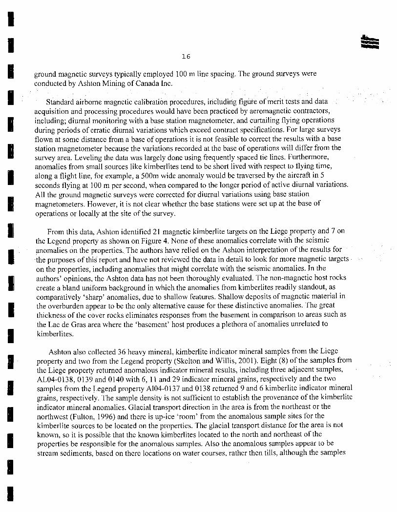
ground magnetic surveys typically employed 100 m line spacing. The ground surveys were conducted by Ashton Mining of Canada Inc.
Standard airborne magnetic calibration procedures, including figure of nierit tests and data acquisition and processing procedures would have been practiced by aeromagnetic contractors, including; diurnal monitoring with a base station magnetometer, and curtailing flying operations during periods of erratic diurnal variations which exceed contract specifications. For large surveys flown at some distance from a base of operations it is not feasible to correct the results with a base station magnetometer because the variations recorded at the base of operations will differ from the survey area. Leveling the data was largely done using frequently spaced tie lines. Furthermore, anomalies from small sources like kimberlites tend to be short lived with respect to flying time, along a flight line, for example, a 500m wide anomaly would be traversed by the aircraft in 5 seconds flying at 100 m per second, when compared to the longer period of active diurnal variations. All the ground magnetic surveys were corrected for diurnal variations using base station magnetometers. However, it is not clear whether the base stations were set up at the base of operations or locally at the site of the survey.
From this data, Ashton identified 21 magnetic kimberlite targets on the Liege property and 7 on the Legend property as shown on Figure 4. None of these anomalies correlate with the seismic anomalies on the properties..The authors have relied on the Ashton interpretation of the results for the purposes of this report and have not reviewed the data in detail to look for more magnetic targets on the properties, including anomalies that might correlate with the seismic anomalies. In the authors' opinions, the Ashton data has not been thoroughly evaluated. The non-magnetic host rocks create a bland uniform background in which the anomalies from kimberlites readily standout, as comparatively 'sharp' anomalies, due to shallow features. Shallow deposits of magnetic material in the overburden appear to be the only alternative cause for these distinctive anomalies. The great thickness of the cover rocks eliminates responses from the basement in comparison to areas such as the Lac de Gras area where the 'basement' host produces a plethora of anomalies unrelated to kimberlites.
Ashton also collected 36 heavy mineral, kimberlite indicator mineral samples from the Liege
I property and two from the Legend property (Skelton and Willis, 2001). Eight (8) of the samples from the Liege property returned anomalous indicator mineral results, including three adjacent samples,
I AL04-0138, 0139 and 0140 with 6, 11 and 29 indicator mineral grains, respectively and the two samples from the Legend property A104-0137 and 0138 returned 9 and 6 kimberlite indicator mineral grains, respectively. The sample density is not sufficient to establish the provenance of the kimberlite
I indicator mineral anomalies. Glacial transport direction in the area is from the northeast or the northwest (Fulton, 1996) and there is up-ice 'room' from the anomalous sample sites for the kimberlite sources to be located on the properties. The glacial transport distance for the area is not
I known, so it is possible that the known kimberlites located to the north and northeast of the properties be responsible for the anomalous samples. Also the anomalous samples appear to be stream sediments, based on there locations on water courses, rather then tills, although the samples
I I

II II II II II I I I I I I I
17
are not specifically identified as stream sediments by Ashton, where fluvial winnowing could lead to higher than normal heavy mineral grain concentrations.
DRILLING Ashton drilled one hole (DDHRLI-01) to test an aeromagnetic anomaly (RL-1) in the vicinity
of the Legend property but it is not directly on the property. There are a large number of natural gas exploration and production wells in the area that are not germane to kimberlite exploration.
SAMPLING METHOD AND APPROACH All the sampling on the property was done previously by Ashton Mining of Canada Inc.
Ashton and its joint venture partners have followed a systematic approach to diamond exploration in the Canadian north involving the use of regional till sampling in conjunction with airborne and ground magnetic and electromagnetic surveys, any or all of which can assist in locating kimberlite bodies. Dispersion trains of indicator minerals, mineral assemblages generally considered unique to kimberlites, are disbursed by forces of erosion but can be detected by heavy mineral analyses and through careful sampling the dispersion train followed back to its source. Once an area is selected from regional surveys detailed grid based till sampling and ground geophysical surveys, in conjunction with mapping and prospecting are used to select prospective areas for drill testing. A discovery of kimberlite on surface can lead directly to the drilling phase.
SAMPLE PREPARATION, ANALYSIS AND SECURITY All the sampling on the property was done previously by Ashton Mining of Canada Inc.
Samples are collected with the aid of helicopter; a UPS system is utilized to record the sample location. Samples locations and relevant sample and geological data are logged into a computer database. Samples are securely stored on site. All samples are shipped to Ashton's North Vancouver laboratory for preparation and analysis; Ashton employees have complete control of the sample "chain of custody".
I Till samples of approximately 25 kg are collected from sites prospective for the trapping of heavy minerals. If grid based till sampling is conducted then generally speaking the sample size is
I smaller but the sample density is much greater. In areas of in-situ kimberlite, or kimberlite float and talus rock samples of varying weights are collected and analyzed. The heavy mineral samples are collected in bags, sealed with security tags and shipped to the Ashton North Vancouver lab by truck.
I During the kimberlite drilling phase, kimberlite core is collected in core boxes which are shipped to the Ashton North Vancouver lab by truck. Ashton employees supervise all aspects of the sampling handling and shipping procedures.
The author Cavey has reviewed the Ashton sampling procedures. It is the authors' opinion that the Ashton sampling, sample preparation, security and analytical procedures are adequate and meetor exceed the standards as discussed in NI 43-101. The successful discovery of 36 kimberlites in the Buffalo Head Hills area of which 24 are diamondiferous is evidence that the techniques used
by Ashton are appropriate in Alberta. DATA VERIFICATION
I

I II
to 18
The authors can-not ensure the quality of the data and results presented in this report as all the data was collected directly by Ashton personnel and therefore the authors must rely upon the professional measures used by the employees of Ashton for all aspects sampling and analytical procedures The author Cavey has reviewed the Ashton quality control procedures and are of the opinion that the quality control measures Ashton has in place are adequate and meet or exceed the standards as discussed in NI 43-10 1. The authors havecompleted no independent sampling on the Legend and Leige properties and are of the opinion that none is required at this early stage of the exploration program.
ADJACENT PROPERTIES It was the Ashton/Pure GoldfEnCana discovery of diamond-bearing kimberlites in the
Buffalo Head Hills area of northern Alberta that triggered a province-wide staking rush in 1997. At its peak in early 1998, more than 50 different junior exploration companies held an interest in various permits. Unfortunately, disappointing results in 1998 deflated the play. Drilling programs by Lucero Resource, Meteor Minerals, Primero Industries and Montello Resources, primarily on geophysical anomalies were all unsuccessful at locating new kimberlites (Northern Miner, Vol. 85, No. 7, April 12-18, 1999).
There are 36 known kimberlite occurrences on the Ashton Mining of Canada Inc., Buffalo Hills property immediately to the west of the Liege property of which 24 are diamondiferous (Cavey, 2002). The grades of the 6 best occurrences in carats/ l00 tonnes are as follows (Cavey, 2002); K252 - 55.0, K14 - 17.0 (from exploration drilling) - 11.7 (from mini-bulk sample), K91 - 12.7. K6 —9.4, Ku- 4.4 and BH225 —3.5, based on diamonds greater than 0.8 mm in one dimension, except for the K14 mini-bulk sample which is based on diamonds greater than 1.2 mm in one dimension.
Most of the known kimberlites on the Buffalo Hills property have been discovered by drilling 'bull's eye' magnetic highs. One of the known kimberlites, K252, lacks a magnetic signature and
was found by a GEOTEM airborne electromagnetic survey, as a resistivity high. Two of the main pipes, the K14 and the K6, produce distinct anomalies in a horizontal loop electromagnetic survey (Dujakovic and Rockel, 1997) that are interpreted here, by author LeBel, to reflect flat-lying, disk-shaped conductors. Seismic reflection surveys have also been instrumental in finding some of the pipes and have aided in the determining the geometry and structure of the kimberlites. Drilling at the K252 pipe was guided by a well defined, 600 in by 400 in gravity high (Cavey, 2002). Estimated dimensions of the kimberlites from their respective anomalies very from 100 in by 100 in for K160 to 600 m by 600 rn for KS. Ashton's 'show-piece' kimberlite in the area, the K14 pipe, for example, exhibits a 250 in by 150 in 400 nT magnetic high. Four of theknown kimberlites are reported to outcrop (Cavey, 2002) on hills. One eventual pipe is reported to have provided a convenient treeless, helicopter landing site for forestry and natural gas exploration crews prior to its discovery.
Although most of the known kimberlites in the area are magnetic highs, it is well known that kimberlite pipes are compositionally heterogeneous and have variable magnetic susceptibility which results in a variety of magnetic signatures (Macnae, 1979), even within the same cluster, including remnant magnetism lows and no magnetic signature at all (St. Pierre, 1999).
II II I II II I I I I I I I I I I I I

II II
19
In addition, seven kimberlites, referred to as the Legend kimberlites, have been discovered to the north and northeast of the properties by junior resource companies Montello Resources, Redwood Resources, New Blue Ribbon Resources and joint venture partner Keimecott Canada but none of these are apparently diamondiferous (Cavey and Raven, 2002).
The occurrence of diamondiferous kimberlites on adjacent properties is not necessarily indicative of any diamond mineralization on the Liege and Legend properties. However, kimberlites invariably occur in 'clusters', several of which commonly make up 'fields' of kimberlites within a kimberlite 'province' that may span 100's of kilometers. For example, from the single kimberlite discovery at Point Lake in 1991, the Slave diamond province in the Northwest Territories, now incorporates several hundred kimberlites over a distance of 460 km. from the Doyle Lake sill in the south to Kikerk I pipe near the Coronation Gulf in the north and probably extends even farther north to the Diamonds North Resources Ltd. discoveries on Victoria Island.
MINERAL PROCESSING AND METALLURGICAL TESTING Not applicable.
MINERAL RESOURCE AND MINERAL RESERVE ESTIMATION There are no known proven or probable reserves or resources on either of the subject
properties.
INTERPRETATION AND CONCLUSIONS The Liege and Legend properties are located North Central Alberta west of Fort McMurray in
an area where the regional basement geology and structure is favourable for hosting diamond bearing kimberlites. Exploration in the area by Ashton Mining of Canada Inc and partners has lead to the discovery of 36 kimberlite bodies, some of which are diamondiferous, in the Buffalo Hills area just west of the properties and there are seven known kimberlites located to the north and east of the properties.
At least six of the kimberlites in the Buffalo Head Hills kimberlite province have estimated gradesgreater than three carats per hundred, a value Ashton has determined is important when. evaluating the economic potential of a kimberlite province. As in all evaluations of diamond deposits, the presence of commercial-sized and high quality stones is also essential. The Buffalo Head Hills area contains a series of roads and support facilities established by the oil and gas industry that provide easier access and better infrastructure development than exists in other parts of Canada, especially compared with the logistical problems encountered with mine exploration in the NWT. Ashton is of the opinion that the economic threshold for diamond mining in Alberta may be lower than that which exists in more remote regions of the country such as the NWT. The joint venture is encouraged by the regions potential to host an economic diamond deposit and it is highly recommended that exploration continue on the Buffalo Hills joint venture lands.
I I
II I II II II I I I I I I

II II
20
The properties also cover former Rabbit Lake property on which Ashton Mining of Canada Inc and partners carried out regional fixed-wing aeromagnetic surveys, helicopter aeromagnetic and ground magnetic follow-up and kimberlite indicator mineral sampling The properties host a total of 10 magnetic targets that have not been tested by drilling and a review of the data could yield more favourable anomalies. In addition, there are some kimberlite indicator mineral anomalies on the properties, situated such that the source of the anomalies could be located on the properties.
The properties cover lands on which seismic reflection surveys have been conducted in the search for natural gas. In these surveys, there are seven seismic reflection anomalies that are similar to the seismic anomalies over known kimberlites in the area.
There are several available camps and airstrips at natural gas production plants in the area and a network of gas field service roads which simplify the accommodation and transportation logistics on the properties.
It is concluded that the Liege and Legend properties are strategically located in an existing kimberlite field where there are indications of more kimberlites and that an exploration an exploration program is warranted on the properties.
RECOMMENDATIONS The exploration program consisting of the following elements is recommended for the
Legend and Leige properties:
II I II II II II I II
1. Review the existing magnetic geophysical database to confirm pre-existing targets and look for more targets, especially in the vicinity of the seven seismic targets.
2. Conduct fixed-wing airborne geophysical surveys over the part of the Legend property that has not received such coverage. The area involved is 16 of the 22 permits, an area of 147,456 ha. It is possible that pre-existing surveys are available from parts of this area. At 200 m line spacing and tie lines every 5 km the survey entails approximately 7,500 line kilometers.
3. Conduct ground geophysics to prepare the targets for drilling, including the 6 existing seismic targets and any targets developed from (1) and (2).
4. Diamond drill the targets and analyze the samples for diamond content.
Reconnaissance kimberlite mineral sampling on the Legend property. Although airborne geophysics is considered the primary exploration method for the area, the kimberlite indicator mineral sampling might provide some focus and encouragement particularly for kimberlites that do not have a geophysical signature.
Further exploration work will be contingent upon the successful completion of the work recommended in the proposed 2003 work program. The authors recommend that 977554 Alberta Ltd. proceed with the proposed exploration program.
II I I I I I I I I

II II ta
21
II I I I I I I I I I I I I I I I I

II m 22
2003 BUDGET ESTIMATES
I The following budget is estimated for the proposed exploration program:
Airborne Data Review
I Geophysicist $ 15,000 Report preparation 5,000
$ 20,000 Airborne Geophysical Survey 7,500 km @ $40/km
$ 300,000 Interpretation and report
20,000 $ 320,000
Ground geophysics (all inclusive) 12 targets @ $10,000/target $ 120,000 $ 120,000
Diamond Drilling and Analyses (12 targets assumed) Drilling 2000 m @ $150/m (all inclusive) $ 300,000 Road Building 40,000 Analyses 12 samples @ $5000/sample 60,000
$ 400,000, $ 400,000 Kimberlite Indicator Mineral Sampling 50 samples @ $2000/sample (all inclusive) $ 100,000 $ 100,000
Total Direct Exploration $ 960,000 Contingency at 10% 96,000 Operating Costs (supervision, administration, land etc.) 96,000
IGRAND TOTAL $1,152,000I
Dated at Vancouver, British Columbia, this 24th day of April , 2003.
I II II I I I I I I I
$ 20,000
$ 320,000
I
/s/"George Cavey" s/"J.L. LeBel"
I George Cavey, P.Geo. J.L.LeBeI, P.Eng.
I I

II II
23
REFERENCES
BAUMAN, P., 1999a: Geophysical Logging of Boreholes BM2, BM3, BM4 and BM5, Komex International Ltd., letter to
Ashton Mining of Canada Inc., dated Feb 8, in Skelton, D, Willis, D., 2001 Assessment Report for the Loon Lake, Rabbit Lake and Muddy River Properties, Report submitted to Alberta Energy Mineral Development prepared by Ashton Mining of Canada Inc.
BAUMAN, P.,. 1999b: February 1999 Geophysical Logging Program, Komex International ltd., Letter to Ashton Mining of
Canada Inc., dated March 31, in Skelton, D., Willis, D., 2001. Assessment Report for the Loon Lake, Rabbit Lake and Muddy River Properties, Report submitted to Alberta Energy Mineral Development prepared by Ashton Mining of Canada Inc.
DUFRESNE, M.B., ECCLES, D.R., McKINSTRY B., SCHMITT D.R., FENTON M.M., PAWLOWICZ J.G. and EDWARDS W.A.D. 1996: The Diamond Potential of Alberta, Alberta Geological Survey, Bulletin No.63 DUJAKOVIC, Z., ROCKEL, E. 1997: Geophysical Report of HLEM Survey for Ashton Mining of Canada Inc survey by S.J.V. Geophysics
Ltd., report by S.J.V.Consultants Ltd., in Skelton, D., Bursey, T., 1999. Assessment Report, Buffalo Hills (ALOI), Loon Lake (AL02), Birch Mountain (AL03), Rabbit Lake (AL04) and Muddy River (AL05) Properties, Vol. 3 - Appendix C, Ashton Mining of Canada Ltd., East Peace District, Province of Alberta, 1999.
FULTON, R.J. 1996 Surficial Materials of Canada, Geological Survey of Canada Map 1880A GENDZWILL, D.J., MATIESHIN, S.D. 1996: Seismic Reflection Survey of a Kimberlite in the Fort a la Come District, Saskatchewn; in Searching
for Diamonds in Canada, A.N. LeChemineant, D.G. Richardson. R.H.W. DiLabio and K.A. Richardson (ed); Geological Survey of Canada, Open File 3228 p 251 - 252.
HIGH SENSE GEOPHYSICS LTD. 1996: Logistics Report for a Detailed Helicopter Survey of Fourteen Targets in Red Earth Area, Alberta
carried out on behalf of Ashton Mining of Canada Inc., in Skelton, D., Bursey, T., 1999. Assessment Report, Buffalo Hills (ALOI), Loon Lake (AL02), Birch Mountain (AL03), Rabbit Lake (AL04) and Muddy River (AL05) Properties, Vol. 2 - Appendix C, Ashton Mining of Canada Ltd., East Peace District, Province of Alberta, 1999.
HIGH SENSE GEOPHYSICS LTD. 1997: Logistics Report for a Detailed Helicopter Survey over Target Areas in Alberta carried out on behalf
of Ashton Mining of Canada Inc., in Skelton, D., Bursey, T., 1999. Assessment Report, Buffalo Hills (ALO 1), Loon Lake (AL02), Birch Mountain (AL03), Rabbit Lake (AL04) and Muddy River (AL05) Properties, Vol. 2 - Appendix C, Ashton Mining of Canada Ltd., East Peace District, Province of Alberta, 1999.
HIGH SENSE GEOPHYSICS LTD. 1998: Logistics Report for a High Resolution Fixed Wing Magnetic Survey of the Rabbit Lake property,
Northern Alberta carried out on behalf of Ashton Mining of Canada Inc., in Skelton, D., Bursey, T., 1999. Assessment Report, Buffalo Hills (ALOI), Loon Lake (AL02), Birch Mountain (AL03), Rabbit Lake (AL04) and Muddy River (AL05) Properties, Vol. 2 - Appendix C, Ashton Mining of Canada Ltd., East Peace District, Province of Alberta, 1999.
NEWS RELEASES 2001: New Blue Ribbon Resources-March 15, 2001.
II II II II I I I I II I U I I I I I I

I I
tm 24
NEWS RELEASES - ASHTON MINING OF CANADA INC. 2001: August 2, November 19 (and Dec 18, 1997). 2002: April 23, May 29, Aug 16. NEWS RELEASES - PURE GOLD MINERALS INC. 1997 February 4, February 14, April 14, April 25, May 16, June 11, July 21, Aug 8, Sept 11, Oct 2, Oct 31,
Nov 11, 1998: April 1, April 9, July 6, July 27, Sept II, Sept 28. 1999: April 15, April 28, May 14, May 21. 2000: Jan 20, Mar 3, Mar 23, June 20, July 19, Aug 14, Sept 11, Dec 7. 2001: Jan 22, Mar 8, Mar 30, May 3, Aug 2. 2002: Jan 30, Mar 4, May 29, July 18, Aug 16, Sept 23 NORTHERN MINER 1997: Dia Met Minerals and BHP Diamonds -January 6, Ashton Mining and Pure Gold Resources-
February 24 1998: Vol. 83, No. 44; Vol. 83, No. 48; Vol. 83, No. 51; Vol. 83, No. 52; Vol. 84, No. 2; Vol. 84, No. 3;
Vol. 84, No. 4; Vol. 84, No. 6; Vol. 84, No. 38; 1999: Vol. 85, No. 3; Vol. 85, No. 12; Vol. 85, No. 12; PURE GOLD RESOURCES INC. 2001: Annual Information Form (AIF) filed on SEDAR June, 2001. 2002: Personal Communication ROSS, G.M. 1991: Precambrian Basement on the Canadian Cordillera: An Introduction, Canadian Journal of Earth
Sciences Volume 28, No 8, August 1991, pp 1133-1139 ROSS, G.M., PARRISH, R.R., VALLENEUVE, M.E. and BOWRING, S.A. 1989: Tectonic Subdivision and U/Pb Geochronology of the Precambrian Basement of the Alberta Basin,
Western Canada, Geological Survey of Canada, Open File 2103. RUDD, J., 1998: DighemV Survey for Ashton Mining of Canada, Alberta, Brich Mountain and Buffalo Hills
Properties, Geoterrex-Dighem, a division of CGG Canada Ltd., in Skelton, D., Bursey, T., 1999. Assessment Report, Buffalo Hills (ALOI), Loon Lake (AL02), Birch Mountain (AL03), Rabbit Lake (AL04) and Muddy River (AL05) Properties, Vol. 3 - Appendix C, Ashton Mining of Canada Ltd., East Peace District, Province of Alberta, 1999.
SKELTON, D., BURSEY, T., 1999a: Assessment Report, Buffalo Hills (ALOI), Loon Lake (AL02), Birch Mountain (AL03), Rabbit Lake
(AL04) and Muddy River (AL05) Properties, Vol. 1 - Report, Appendix A, Appendix B, Ashton Mining of Canada Ltd., East Peace District, Province of Alberta, 1999.
SKELTON, D., BURSEY, T., 1999b: Assessment Report, Buffalo Hills (ALOI), Loon Lake (AL02), Birch Mountain (AL03), Rabbit Lake
(AL04) and Muddy River (AL05) Properties, Vol. 2 - Appendix C, Ashton Mining of Canada Ltd., East Peace District, Province of Alberta, 1999.
SKELTON, D., BURSEY, T., 1999c: Assessment Report, Buffalo Hills (ALO I), Loon Lake (AL02), Birch Mountain (AL03), Rabbit Lake
(AL04) and Muddy River (AL05) Properties, Vol. 3 - Appendix C, Ashton Mining of Canada Ltd., East Peace District, Province of Alberta, 1999.
SKELTON, D., BURSEY, T.,
I I I I I I I I I I I I I I I I I

I I
25
I 1999d: Assessment Report, Buffalo Hills (ALOI), Loon Lake (AL02), Birch Mountain (AL03), Rabbit Lake (AL04) and Muddy River (AL05) Properties, Vol. 4 - Appendix C through Appendix F, Ashton Mining of Canada Ltd., East Peace District, Province of Alberta, 1999.
U SKELTON, D., WILLIS, D, 2001 Assessment Report for the Loon Lake, Rabbit Lake and Muddy River Properties, Report submitted to
Alberta Energy Mineral Development prepared by Ashton Mining of Canada Inc.
• ST. PIERRE, M., 1999: Geophysical Characteristics of BHP/Diamet Kimberlites, N. W. T., Canada, in Lowe, C., Thomas,
M. D., and Morris, W. A., eds., Geophysics in Mineral Exploration, Fundamentals and Case
I, Histories, Geological Association of Canada, Short Course Notes, v. 14, p. 63 —72.
THERIAULT, R.J., ROSS, G.M. 1991: Nd Isotopic Evidence for Crustal Recycling in the co. 2.0 Ga Subsurface of Western Canada,
ICanadian Journal of Earth Sciences, Volume 28, No. 8, August 199, pp. 1140-1147.
WEBSI TES 2002: Ashton Mining of Canada Inc., Pure Gold Resources Inc., New Claymore Resources Ltd, Troymin
Resources Ltd., Montello Resources Ltd. New Blue Ribbon Resources Ltd.
I I I I I I I I I I I I
I I
ta 26
OREQUEST REPORTS PREVIOUSLY PREPARED CAVEY, G. and FREEZE, J.C. 1993: Report on the Weir Project, for Pure Gold Resources Inc., Northern Alberta. March 5, 1993. CAVEY, G 1997 Report on the Buffalo Head Project, for Pure Gold Resources Inc and Cayo Resources Inc.,
Northern Alberta. April 15, 1997. CAVEY, G. 1997: Report on the Caribou Hills Diamond Project for Pure Gold Resources Inc. and Cayo Resources Inc.,
Northern Alberta. April 15, 1997. CAVEY, G. 1997: Report on the Edmonton Diamond Project for Cayo Resources Inc., Central Alberta. April 16, 1997. CAVEY, G. 1997: Report on the Lethbridge Diamond Project for Cayo Resources Inc., Southern Alberta. Apr 16, 97. CAVEY, G. and RAVEN, W. 1997: Report on the Cadotte River Diamond Property for Blackrun Ventures Inc., May 28, 1997. CAVEY, G. and RAVEN, W. 1997: Report on the Peace River Project for Blackrun Ventures Inc., Northern Alberta. May 30, 1997. CAVEY, G. 1997: Addendum Report on the Peace River Project for Blackrun Ventures Inc., Northern Alta. July] 0, 97. CAVEY, G. and LEBEL, J.L. 1997: Report on the Peace River Diamond Project for Primero Industries Ltd., Northern Alta Nov 25, 97. CAVEY, G. and LEBEL, J.L. 1997 Report on the Peace River Diamond Project for Meteor Minerals Inc., Northern Alberta Nov 25, 97 CAVEY, G. and RAVEN, W. 1998: Summary Report on the Alberta and Saskatchewan Diamond Projects for Pure Gold Minerals Inc., in
the provinces of Alberta and Saskatchewan. January 12, 1998. CAVEY, G. and RAVEN, W. 1998: Report on the Edmonton-North Diamond Project for Pure Gold Minerals Inc., Alberta., Feb 17, 1998. CAVEY, G. and RAVEN, W. 1998: Report on the Edmonton-South Diamond Project for Pure Gold Minerals Inc., Central Alta., Feb 17. CAVEY, G. and RAVEN, W. 1998: Summary Report on the Alberta Diamond Properties Cambridge Minerals Ltd., Apr 24, 1998. CAVEY, G. and RAVEN, W. 1998: Addendum Report on the Alberta Diamond Properties Cambridge Minerals Ltd., June 10, 1998. CAVEY, G. and RAVEN, W. 1998: Summary Report on the Peace River Project for Blackrun Venturçs Inc. August 4, 1998. CAVEY, G. and RAVEN, W. 1998: Report on the Bow River Diamond Project for Starwest Aviation Ltd, Southern Alberta, Feb 23, 1998. CAVEY, G. and RAVEN, W. 1998: Report on the Leland Lakes Alberta Diamond Project for X-Chequer Resources Ltd. North-Eastern
Alberta, Feb 26, 1998. CAVEY, G. 1999: Summary Report on the Alberta Diamond Projects for Pure Gold Minerals Inc., June 15, 1999. CAVEY, G. and RAVEN, W. 2001: Summary Report on the Buffalo Head Hills Diamond Project for Pure Gold , Alberta, Dec 14, 2001. CAVEY, G. 2002: Summary Report on the Alberta Diamond Projects for Pure Gold Minerals Inc., Dec 2.
I I I I I I I I I I I I I I I I I

I I
am 27
I CERTIFICATE OF AUTHOR
I I, George Cavey, of 306-595 Howe Street, Vancouver British Columbia, hereby certify
1 2.
I 3.
4.
I 1 5 I
7.
I 8.
9.
I 1 I I
I am a graduate of the University of British Columbia (1976) and hold a B.Sc. degree in geology. I am presently employed as a consulting geologist with OreQuest Consultants Ltd. of #306-595 Howe Street, Vancouver, British Columbia. I have been employed in my profession by various mining companies since graduation, with OreQuest Consultants Ltd. since 1982. I am a member of the Association of Professional Engineers and Geoscientists of British Columbia, and have been a member since 1992. I am also a member of the Association of Professional Engineers, Geologists and Geophysicists of Alberta and have been a member since 1989 (except for a two-year period from 1999-2001). I am also a member of the Association of Professional Engineers and Geoscientists of Manitoba. I have read the definitions of "Qualified Person" set out in NI 43-101 and certify that by reason of my education, affiliation with a professional association (as defined in NI 43-101) and past relevant work experience, I fulfil the requirements to be a "Qualified Person" for the purposes of NI 43-101. I am a co-author of this report utilizing data summarized in the References section of this report. I have not visited the subject property. I have had no previous direct involvement with the Legend or Leige properties although from 1993-2002, I have been the author or co-author of 20 technical reports dedicated to Alberta Diamond Exploration. I am not aware of any material fact or material change with respect to the subject matter of the technical report which is not reflected in the technical report, the omission to disclose which makes the technical report misleading. I am independent of 977554 Alberta Ltd. and Paramount Resources Ltd. applying all the tests in Section 1.5 of NI 43-101. I have read NI 43-101 and NI 43-101F1 and the technical report has been prepared in compliance with that instrument and form. I consent to the use of this report for the purpose of complying with the requirements set out in NI 43-101 for completing a 977554 Alberta Ltd. Prospectus and to be submitted to SEDAR for electronic filing.
/s/"George Cavey"
George Cavey, P. Geo.
I DATED at Vancouver, British Columbia, this 24th day of April ,2003.
I I

to 28
CERTIFICATE OF AUTHOR
I, J. L. LeBel, P. Eng., am a Professional Engineer living at 2684 Violet Street in the City of North Vancouver in the province of British Columbia hereby certify
1. I graduated from Queen's University with a Bachelor of Applied Science degree in geological engineering in 1971, and I obtained a Master of Science degree in geophysics from the University of Manitoba in 1973.
2. I am presently a Senior Geophysicist with Orequest Consultants Ltd., 306 - 595 Howe Street, Vancouver, B.C., V6C 2T5.
3. I have been employed in my profession by various mining companies since graduation in 1972. I have been involved in diamond exploration from time to time since 1992 as a geophysical consultant on properties in the Northwest Territories, Nunavut, Greenland, Alberta, Ontario and Quebec.
4. I am a member of the Association of Professional Engineers and Geoscientists of British Columbia and have been since 1984.
5. I have read the definitions of "Qualified Person" set out in NI 43-10 1 and certify that by reason of my education, affiliation with a professional association (as defined in NI 43-101) and past relevant work experience, I fulfil the requirements to be a "Qualified Person" for the purposes of NI 43-101.
6 I am the co-author of this report prepared using the data and information from the reports listed in the References section of this report. I have relied on data and information from previous work done on the property without verifying such data and information.
7. I visited the properties on April 16, 2003 which entailed flying over some of the geophysical anomaly sites in a helicopter and briefly examining one site on the ground.
8. I have had no previous direct involvement with the Legend or Leige properties. 9. I am not aware of any material fact or material change with respect to the subject matter of the
technical report which is not reflected in the technical report, the omission to disclose which makes the technical report misleading.
10. I am independent of 977554 Alberta Ltd. and Paramount Resources Ltd. applying all the tests in Section 1.5 of NI 43-101.
11. I have read NI 43-101 and NI 43-1O1F1 and the technical report has been prepared in compliance with that instrument and form.
12. I consent to the use of this report for the purpose of complying with the requirements set out in NI 43-10 1 for completing a 977554 Alberta Ltd. Prospectus and to be submitted to SEDAR for electronic filing.
I I I I 1 I I I I I I I I 1 U I
/s/"J.L. LeBel"
I
J.L. LeBel, P. Eng.
DATED at Vancouver, British Columbia, this 24th day of April, 2003.
U I

29
I I I I I . I I I I I I I I I I I I I I
APPENDIX I
METALLIC AND INDUSTRIAL PERMIT SCHEDULE
LIEGE AND LEGEND PROPERTIES

t~i 30
APPENDIX I: METALLIC AND INDUSTRIAL PERMIT SCHEDULE LIEGE AND LEGEND PROPERTIES
Permit Number Location Area (ha) Effective Date Meridian-Range-Township: Section
LEGEND 9302050130 4-14-90:1-36 9216.00 May 24, 2002
9302050131 4-15-90:1-36 9,216.00 May 24, 2002
9302050132 4-16-90:1-36 9,216.00 May 24, 2002
9302050135 4-14-91: 1-3, 10-15, 22-27, 34-36 9,216.00 May 24, 2002
4-14-92: 1-3, 10-15,22-27,34-36
9302050136 4-14-91:4-9,16-21,28-33 9,216.00 May 24, 2002
4-14-92:4-9, 16-21, 28-33
9302050137 4-15-91: 1-18 9,216.00 May 24, 2002
4-16-91: 1-18
9302050138 4-15-91: 19-36 9,216.00 May 24, 2002
4-16-91: 19-36
9302050139 4-15-92: 1-18 9,216.00 May 24, 2002
4-16-92: 1-18
9302050140 4-15-92: 19-36 9,216.00 May 24, 2002
4-16-92: 19-36
9302050141 4-17-92: 1-36 9,216.00 May 24, 2002
9302050142 4-14-93: 1-3, 10-15, 22-27, 34-36 9,216.00 May 24, 2002 4-14-94: 1-3, 10-15,22-27,34-36
9302050143 4-14-93: 4-9, 16-21, 28-33 9,216.00 May 24, 2002 4-14-94: 4-9, 16-21, 28-33
9302050144 4-17-93: 1-36 9,216.00 May 24, 2002
9303031176 4-13-90: 1-36 9,216.00 March 18, 2003
9303031177 4-13-91: 1-36 9,216.00 March 18, 2003
9303031178 4-13-92: 1-36 9,216.00 March 18, 2003
9303031179 4-13-93: 1-36 9,216.00 March 18, 2003
9303031180 4-13-94: 1-36 9,216.00 March 18, 2003
9303031181 4-17-90: 1-36 9,216.00 March 18, 2003
9303031182 4-17-91: 1-36 9,216.00 March 18, 2003
9303031183 4-18-91: 1-36 9,216.00 March 18, 2003
9303031184 4-18-92: 1-36 1 9,216.00 March 18, 2003 22 Permits 1 202,752 ha I
I I I I I I I I U I I I I U I U U I U
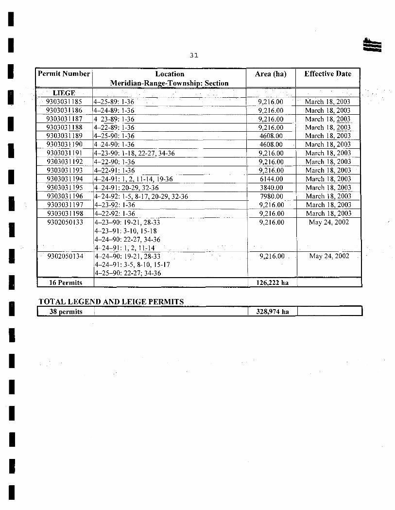
Im 31
Permit Number Location Area (ha) Effective Date Meridian-Range-Township: Section
LIEGE
9303031185 4-25-89: 1-36 9,216.00 Marôh 18, 2003
9303031186 4-24-89: 1-36 9,216.00 March 18, 2003
9303031187 4-23-89: 1-36 9,216.00 March 18, 2003
9303031188 4-22-89: 1-36 9,216.00 March 18, 2003
9303031189 4-25-90: 1-36 4608.00 March 18, 2003
9303031190 4-24-90: 1-36 4608.00 March 18, 2003
9303031191 4-23-90: 1-18,22-27,34-36 9,216.00 March 18, 2003
9303031192 4-22-90: 1-36 9,216.00 March 18, 2003
9303031193 4-22-91: 1-36 9,216.00 March 18, 2003
9303031194 4-24-91: 1,2,11-14,19-36 6144.00 March 18,2003
9303031195 4-24-91:20-29,32-36 3840.00 March 18, 2003
9303031196 4-24-92: 1-5, 8-17, 20-29, 32-36 7980.00 March 18, 2003
9303031197 4-23-92: 1-36 9,216.00 March 18, 2003
9303031198 4-22-92: 1-36 9,216.00 March 18, 2003
9302050133 4-23-90: 19-21,28-33 9,216.00 May 24, 2002 4-23-91: 3-10, 15-18 4-24--90: 22-27, 34-36 4-24-91:1,2,11-14
9302050134 4-24-90 19-21,28 33 9,21600 May 24,2002 4-24-91:3-5,8-10,15-17 4-25-90: 22-27; 34-36
16 Permits 1 126,222 ha
TOTAL LEGEND AND LEIGE PERMITS
I 38 permits 1 1 328,974 ha
I I I I I I I I I I I A I I I I I I I
> -o -o m z
><

I I 1
977554 Alberta Ltd.
1 ASSESSMENT REPORT
I
LEGEND PROSPECT
1 I I I I,
I I I I, I
-1 I
APPENDIX 2 Indicator Sampling Results
Bob Ryziuk Geolirik Exploration Ltd. 10961 University Avenue Edmonton, Alberta T6G 1Y1
977554 Alberta Ltd. 4700 - 888 3rd Street SW
Calgary, Alberta T2P 5C5

FT'
I C.F. MINERAL RESEARCH LIMITED
1677 POWICK ROAD KELOWNA, BRITISH COLUMBIA
ICANADA V1X 41-1
30 December 2003
I Mr. Bob Ryziuk
I GEOLINK EXPLORATION LTD. 10961 University Ave Edmonton, Alta. T6G IYI
I INVOICE
HEAVY MINERAL CONCENTRATION
I of 11 till (clay) samples To MAKE -16+60 HIL, HPY, HD, HM and -60 H
TEL (250) 860-8525 FAX (250) 862-9435
INVOICE# : 9032972 CFM W.O. : DB34 BATCH : 03-2310
Client Ref: Series : LE.. and LW..
High recovery diamond indicator extraction package (clay) Wet sieving, sizing, semigravity concentration, drying and dry sieving concentrates up to: 3 kg of -16+35 3 kg of -35+60 all -60
• • Tetrabromoethane separation using 0.5-1.0 micron triple filtration of three 3 kg concentrates (46+35, 45+60 and -60)
I . Sieving and electromagnetic separation of up to 500 grams of heavy
concentrate to make 4 diamond indicator fractions (HIlL, IHPY, IHD, HIM)
I sample HM-311)-16C-33-4M @ $185.00/sample 185.00
I 9 samples HRH20-C-4M @ $220.00/sample 1,980.00
I sample @ $255.00lsamp(e 255.00
I Optional processing: - Processing overweight samples in additional 12 kg increments
0 overweight increments I1.5143-OPT.OW
' Process through TBE additional 3 kg dry concentrate
I 9 concentrates HRH-52-D.OPT.TBE @ $ 25.7513 kg 231.75 Collect and clean all TBE 'light' fraction
o samples HRH.53-D-OPT-L
I Methylene iodide separation using 0.5-1.0 micron triple filtration of up to 250 cc HI concentrate (or representative split)
11 concentrates HRH-544)-OPT-M1 © $ 36.501250 cc 401.50
I '/ Make any additional four Dl magnetic fractions
- 3 samples (no electromagnetic separation) HRH-00-"PT-MAG -$ 23.75 each -71.25 ' Create and complete sample record form
11 samples HRH-66-D-OPT-REP @ $ 7.001sample 77.00
Sub Total 3,059.00 7% G.S.T. (10090 5777 RT0001) 214.13
I Total this invoice in Canadian Funds C$3,273.13 Terms: Payment due upon receipt of invoice
I
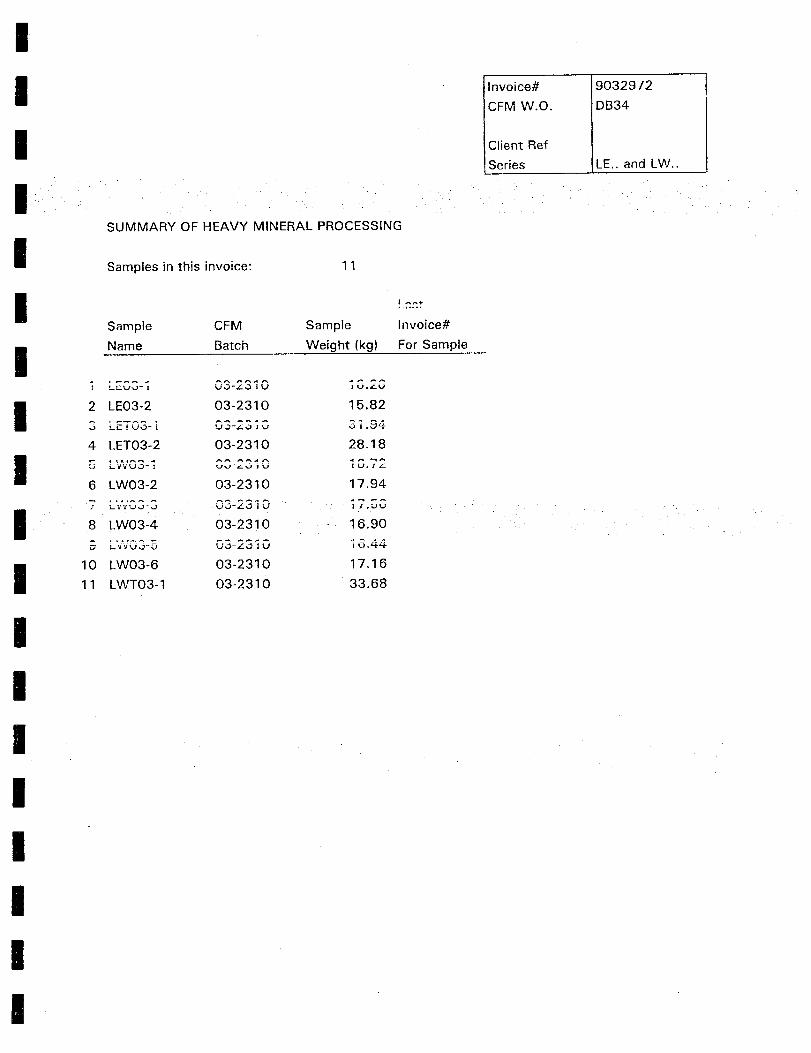
I I I I
SUMMARY OF HEAVY MINERAL PROCESSING
1 Samples in this invoice:
Invoice#
CFM W.O.
Client Ref
Series
9032972
DB34
LE.. and LW..
Sample CFM Sample !nvoice#
Name Batch Weight (kg) For Sample
U IV
I 2 LE03-2 03-2310 1582
-
4 LET03-2 03-2310 28.18
6 LW03-2 03-2310 17.94
I.Z
8 LW03-4 03-2310 16.90
rj L-iVU..j - U 10.9-9-
I 10 LW03-6 03-2310 17.16
11 LWT03-1 03-2310 33.68
I I I I I I I I

I I I I I I
C.F. MINERAL RESEARCH LIMITED 1677 POWICK ROAD
KELOWNA, BRITISH COLUMBIA CANADA V1 41-1
TEL (250) 860-8525 FAX (250) 862-9435
130 December 2003 INVOICE# : 9032973 CFM W.O. : DB34 BATCH : 03-2310
Mr. Bob Ryziuk GEOLINK EXPLORATION LTD.
I10961 University Ave. Edmonton, Alta. T6G lvi
Client Ref: Series : LE.. and LW..
INVOICE
DIAMOND INDICATOR PICKING of -16+60 fractions from 11 samples
Optical Picking Diamond Indicator Mineral Grains
I . Pick representative portions of the specified concentrates •Pick for kimberlitic, tamproitic and diamond indicator minerals • Especially purple pyrope, chrome diopside, possible orange eclogitic
I garnet, chromite, picroilmenite and a representative number of any divine, orthopyroxene and tourmaline indicators Includes detailed picking and complete checking of both the picked indicator grains and the fully picked portion of the concentrates
27.75 hours pLK-11-D-KUIIM c $ 32.601hour
Sub Total
IG.S.T. (10090 5777 RT0001)
Total this invoice in Canadian Funds Terms: Payment due upon receipt of invoice
I I I
904.65
904.65 63.33
C$967.98
I
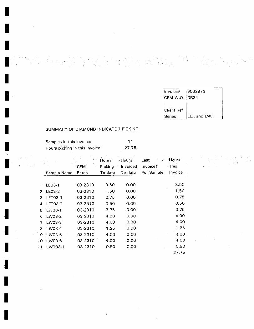
I I I I I I I I
I I I I I I I I I I I
Invoice# 9032973
CFM W.O. I DB34
Client Ref
Series LE.. and LW..
SUMMARY OF DIAMOND INDICATOR PICKING
Samples in this invoice: 11
Hours picking in this invoice: 27.75
Hours Hours Last Hours
CFM Picking Invoiced Invoice# This
Sample Name Batch To date To date For Sample Invoice
1 LE03-1 03-2310 3.50 0.00 3.50
2 LE03-2 03-2310 1.50 0.00 1.50
3 LET03-1 03-2310 0.75 0.00 0.75
4 LET03-2 03-2310 0.50 0.00 0.50
5 LW03-1 03-2310 3.75 0.00 3.75
6 LW03-2 03-2310 4.00 0.00 4.00
7 LW03-3 03-2310 4.00 0.00 4.00
8 LW03-4 03-2310 1.25 0.00 1.25
9 LW03-5 03-2310 4.00 0.00 4.00
10 LW03-6 03-2310 4.00 0.00 4.00
11 LWT03-1 03-2310 0.50 0.00 0.50
27.75
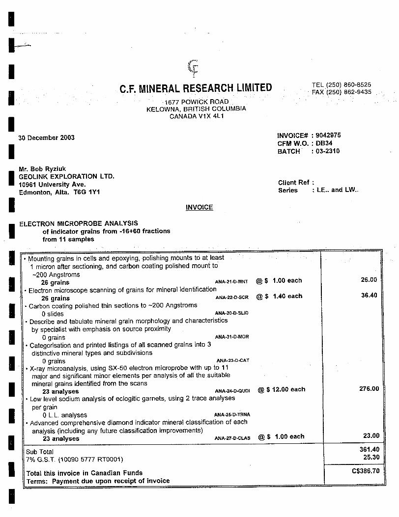
I U— I I I
30 December 2003
I I
Mr. Bob Ryziuk GEOLINK EXPLORATION LTD. 10961 University Ave. Edmonton, Alta. T6G IYI
I
c ,.
C.F. MINERAL RESEARCH LIMITED 1677 POWICK ROAD
KELOWNA, BRITISH COLUMBIA CANADA V1X 41-1
INVOICE
TEL (250) 860-8525 FAX (250) 862-9435
INVOICE# : 9042976 CFM W.O. : DB34 BATCH :03-2310
Client Ref Series : LE.. and LW..
I ELECTRON MICROPROBE ANALYSIS
of indicator grains from -16+60 fractions from 11 samples
• Mounting grains in cells and epoxying, polishing mounts to at least 1 micron after sectioning, and carbon coating polished mount to –200 Angstroms
26 grains ANA-21-D-MNT © $ 1.00 each
• Electron microscope scanning of grains for mineral identification 26 grains ANA-22-D-SCR © $ 1.40 each
• Carbon coating polished thin sections to –200 Angstroms 0 slides ANA-20-D-SLID
• Describe and tabulate mineral grain morphology and characteristics by specialist with emphasis on source proximity
0 grains ANA.31-D-MOR
• Categorisation and printed listings of all scanned grains into 3 distinctive mineral types and subdivisions
0 grains ANA-23-D.CAT
• X-ray microanalysis, using SX-50 electron microprobe with up to 11 major and significant minor elements per analysis of all the suitable mineral grains identified from the scans
23 analyses ANA-24-D-QUD1 @ $ 12.00 each
• Low level sodium analysis of eclogitic garnets, using 2 trace analyses per grain
0 L.L. analyses ANA-25-D.TRNA
• Advanced comprehensive diamond indicator mineral classification of each analysis (including any future classification improvements)
23 analyses ANA-27-D-CLAS © $ 1.00 each
Sub Total 7% G.S.T. (10090 5777 RT000I)
Total this invoice in Canadian Funds Terms: Payment due upon receipt of invoice
I I I I I I I I I
26.00
36.40
276.00
23.00
361.40 25.30
C$386.70
I
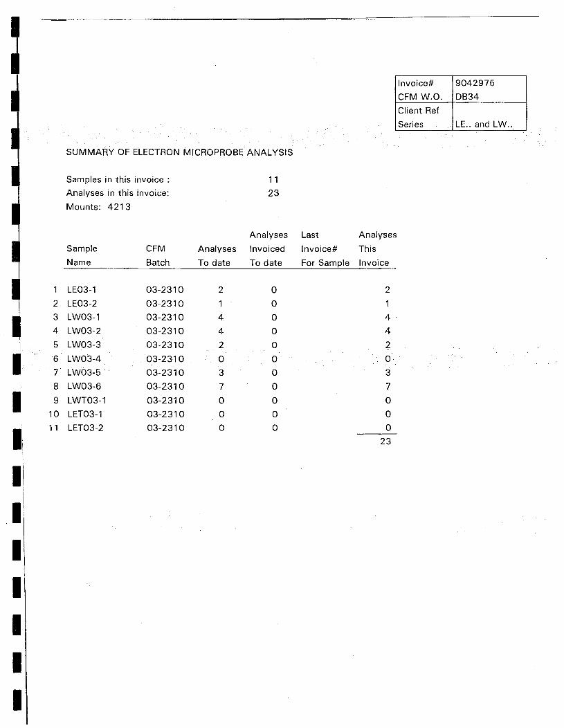
Invoice# 9042975
CFM W.O. DB34
Client Ref
Series LE.. and LW..
SUMMARY OF ELECTRON MICROPROBE ANALYSIS
Samples in this invoice
11
Analyses in this invoice:
23
Mounts: 4213
Analyses Last Analyses
Sample CFM Analyses Invoiced Invoice# This
Name Batch To date To date For Sample Invoice
I
I I I I I I I
1 LEO3-1
2 LEO3-2
3 LWO3-1
4 LWO3-2
5 LWO3-3
6 LWO3-4
7 LWo3-
8 LW03-6
9 LWT03-1
10 LETO3-1
11 LETO3-2
03-2310
03-2310
03-2310
03-2310
03-2310
03-2310
03-2310
03-2310
03-2310
03-2310
03-2310
2
1
4
4
2
0
3
7
0
0
0
0
0
0
0
0
0
0
0
0
0 •
0
2
1
4
4
2
0
3
7
0
0
0
23
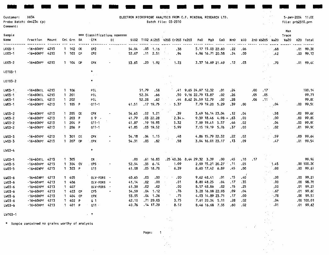
- - - - - - - - - - - - - - - - - - -
Customer: DB34 ELECTRON MICROPROBE ANALYSIS FROM.C.F. MINERAL RESEARCH LTD. 5-Jan-2004 11:OE
Probe Batch: ciec23c (p) Batch File: 03-2310 File: prb2310.prn Comment:
Max Sample Classifications Trace Name Fraction Mount Cel Grn SA CFM DI 5i02 Ti02 A1203 V203 Cr203 Fe203 FeO MgO CaO MnO NiO ZnO Nb205 Na20 Na20 K20 Total
LE03-1 -16+60HPY 4213 1 102 CE CP2 - 54.04 .03 1.16 .38 5.17 15.03 22.60 .22 .06 .68 .01 99.3E
LE03-1 -16+60HPY 4213 1 103 CP CP2 52.67 .11 2.51 .94 4.96 16.71 20.58 .24 .00 .42 .00 99.1
LE03-2 -16460HPY 4213 1 104 CP CPX - 53.65 .20 1.92 1.23 3.37 16.69 21.49 .12 .03 .70 .01 99.4C
LETO3-1 *
LETO3-2 *
LW03-1 -16460H1L 4213 1 106 PIL 51.79 .58 .41 9.65 24.97 12.32 .01 .24 .00 .17 100.1
LW03-1 -16460H1L 4213 1 201 PIL 52.34 .66 .50 9.16 22.79 13.87 .02 .26 .05 .05 99.71
LW03-1 -16460H1L 4213 1 202 PIL 52.28 .62 .44 8.62 24.59 12.79 .02 .28 .06 .11 99.8C
LW03-1 -16+60HpY 4213 1 105 P 011-1 41.51 .17 19.75 5.37 7.79 19.20 5.29 .39 .00 .04 .00 99.5C
LW03-2 -16+60HPY 4213 1 205 CE CPX - 54.63 .02 1.21 .39 3.49 16.14 23.04 .12 .04 .58 .00 99.6
LW03-2 -16+60HPY 4213 1 203 p G 9 41.79 .03 22.28 2.34 9.39 18.46 4.98' .63 .00 .00 .00 99.85
LW03-2 -16+60HPY 4213 1 204 p 011-1 41.87 .19 19.93 5.32 7.09 19.41 5.57 .46 .02 .04 .00 99.9C
LW03-2 -16+60HPY 4213 1 206 P 011-1 41.85 .03 19.52 5.99 7.15 19.19 5.76 .37 .00 .02 .01 99.9C
LW03-3 -16+60HPY 4213 1 301 CE CPX - 54.18 .04 1.15 .48 4.86 15.79 22.32 .22 .02 .59 .00 99.6
LW03-3 -16+60HPY 4213 1 207 CP CPX - 54.31 .03 .82 .58 3.94 16.01 23.17 .13 .09 .47 .01 99.5
LWO3-4 *
LW03-5 -16+60HIL 4213 1 305 CR .00 .61 16.83 .25 40.36 8.4429.32 3.39 .00 .45 .10 .17 99.92
LW03-5 -16+60HPY 4213 1 304 CV CP5 - 52.54 .35 6.14 1.09 2.99 15.21 20.27 .11 .05 1.45 .00 100.2C
LW03-5 -16+60HPY 4213 1 303 P Gil 41.08 .05 18.78 6.39 8.60 17.42 6.89 .45 .00 .00 .00 99.67
LW03-6 16+60HPY 4213 1 405 OLV-FORS - 40.65 .03 .00 .00 9.62 48.41 .01 .15 .40 .00 .00 99.27
LW03-6 -16+60HPY 4213 1 406 OLV-FORS - 41.14 .02 .00 .01 8.80 48.25 .04 .17 .35 .00 .00 98.7E
LW03-6 -16+60HPY 4213 1 407 OLV-FORS - 41.38 .02 .02 .00 8.57 48.86 .02 .15 .25 .00 .01 99.27
LW03-6 •16+60HPY 4213 1 403 CP CP5 - 54.59 .04 1.12 .76 3.28 16.08 22.93 .09 .04 .67 .01 99.6C
LW03-6 -16+60HPY 4213 1 404 CP CPX 53.95 .04 1.26 .75 4.03 14.89 23.71 .17 .00 .78 .00 99.57
LW03-6 -16+60HPY 4213 1 402 p 0 1 42.10 .71 20.03 3.75 7.61 20.34 5.11 .28 .02 .04 .00 100.01
LW03-6 -16+60HPY 4213 1 401 p G11 40.76 .14 17.29 8.12 8.46 16.68 7.55 .60 .02 .01 .01 99.63
LWTO3-1 *
* Sample contained no grains worthy of analysis
Page: 1
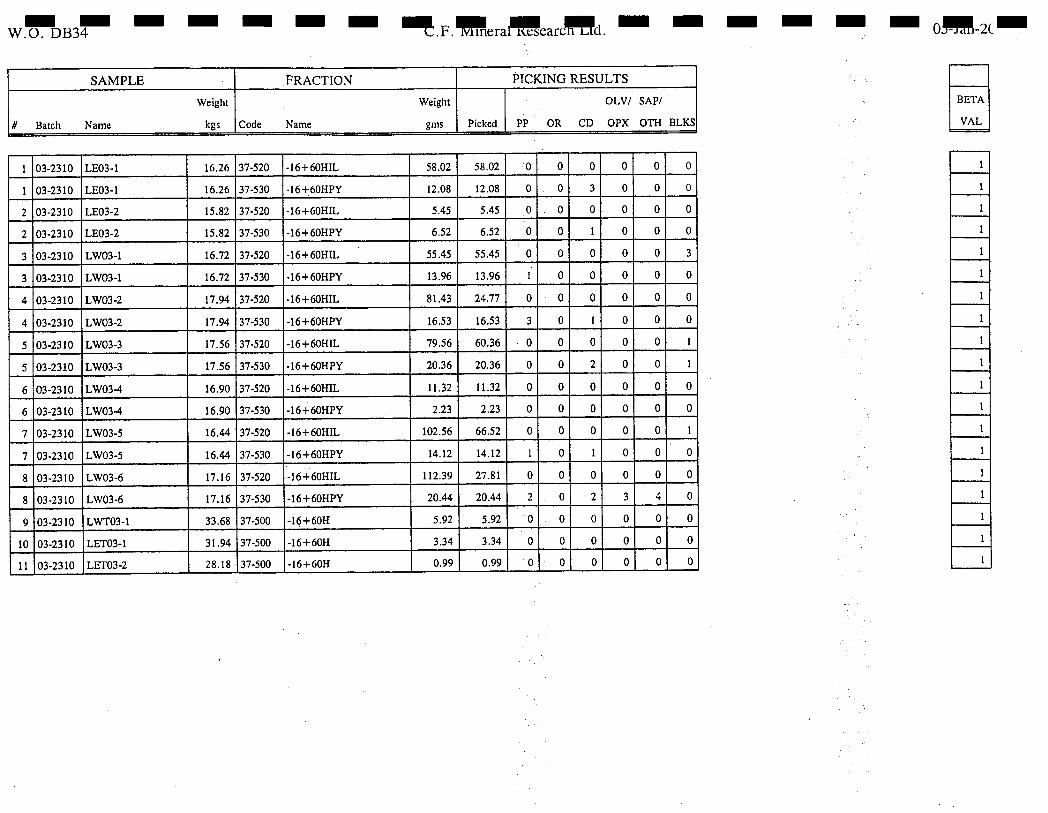
WB3 .F.era1earcd. 0-2C
SAMPLE FRACTION PICKING RESULTS
Weight Weight OLV/ SAP/
ft Batch Name kgs Code Name gms Picked PP OR CD OPX 0TH I3LKS
1 03-2310 LE03-1 16.26 37-520 -16+60HIL 58.02 58.02 0 0 0 0 0 0
1 03-2310 1 LE03-1 16.26 37-530 -16+60HPY 12.08 12.08 0 0 3 0 0 0
2 03-2310 LE03-2 15.82 37-520 -16+60HIL 5.45 5.45 0 0 0 0 0 0
2 03-2310 LE03-2 15.82 37-530 •16+60HPY 6.52 6.52 0 0 1 0 0 0
3 03-2310 LW03-1 16.72 37-520 -16+60HIL 55.45 55.45 0 0 0 0 0 3
3 03-2310 1 LW03-1 16.72 37-530 -16+60HPY 13.96 13.96 1 0 0 0 0 0
4 03-2310 1 LW03-2 17.94 37-520 -16+60HIL 81.43 24.77 0 0 0 0 0 0
4 03-2310 LW03-2 17.94 37-530 -16+60HPY 16.53 16.53 3 1 0 1 0 0 0
5 03-2310 LW03-3 17.56 37-520 -16+60HIL 79.56 60.36 0 0 0 0 1 0 1 1
5 03-2310 LW03-3 17.56 37-530 -16+60HPY 20.36 20,36 0 0 2 0 0 1
6 03-2310 LW03-4 16.90 37-520 -16+60HIL 11,32 11.32 0 0 0 0 0 0
6 03-2310 LW03-4 16.90 37-530 -16+60HPY 2.23 2,23 0 0 0 0 0 0
7 03-2310 1 LW03-5 16.44 37-520 -16+60HIL 102.56 66.52 0 0 0 0 0 1
7 03-2310 LW03-5 16.44 37-530 -16+60HPY 14.12 14.12 1 0 1 0 0 0
8 03-2310 LW03-6 17.16 37-520 -16+60HIL 112.39 27.81 0 0 0 0 0 0
8 03-2310 LW03-6 17.16 37-530 -16+60HPY 20.44 20.44 2 0 2 3 4 0
9 03-2310 LWT03-1 33.68 37-500 -16+60H 5.92 5.92 0 0 0 0 0 0
10 03-2310 LET03-1 1 31.94 37-500 -16+60H 3.34 3.34 0 0 0 0 0 0
1 03-2310 LETO3-2 28.18 37-500 -16+60H 0.99 0.99 0 0 0 0 0 0 1 0
BETA
VAL

F I
DIAMOND INDICATOR FRACTION DESCRIPTIONS
I I -m+ri -
I I I
+n -
I I H- -
I I
I I
the size fraction, where in defines the upper size (based on Tyler sieve size) limit and n the lower size limit. Grains found in this size fraction possess dimensions somewhere between these limits.
the size fraction, where m defines the upper size limit (based on the Tyler sieve size). Grains found in this size fraction possess dimensions m and smaller.
the size fraction, where n defines the lower size limit (based on the Tyler sieve size). Grains found in this size fraction possess dimensions n and larger.
High density fraction ("heavies") consisting of grains which possess specific gravities normally greater than -3.1.
Intermediate density fraction ("intermediates") consisting of grains which possess specific gravities less than the H fraction, but greater than the L fraction. (2.9--3. 1)
Low density fraction ("lights") consisting of grains which possess specific gravities less than that of the I fraction, normally less than '2.9.
M -
IL -
PY -
D -
H MPCODE.WP6
Magnetite magnetic fraction, consisting of grains which are ferromagnetic (e.g. magnetite).
Ilmenite magnetic fraction, consisting of grains which possess strong magnetic susceptibilities (e.g. picroilmenite, chromite).
Pyrope/Chromium Diopside magnetic fraction, consisting of grains which possess weak magnetic susceptibilities.
Diamond magnetic fraction consisting of grains which possess weak or no magnetic susceptibilities
Page 1 of 2 C.F. MINERAL RESEARCH LTD.
I I I I I I I

- Examples -16+32 H D, -32+60 H IL, -32+60 H PY
- Typical mesh used and the respective wire space sizes Mesh Aperture (mm) 16 1.0 32 0.5 60 0.25
Beta Value calculation: IH-A = weight in grams of all the sinks from TBE IH = the weight in grams of that proportion of IH-A
submitted for MT separation Beta Value = IH-A
IH
Thus, if all of the IH-A is submitted for MI separation, Beta = 1. If Beta> 1 then there is some IH-A available. Therefore, if 8 purples are found in the appropriate fraction from a sample with a Beta value of 1 5, then one might expect, within statistical limits, there to be 12 purples (8x1 .5) from the whole sample.
Page 2 of 2 C.F. MINERAL RESEARCH LTD.
U I I
Fraction
Sieve
I I I Beta
I I I I I I I I I I I I HMPCODE.WP6
I

I I I I I I I I I I I I I I I I I I I
PICKING DATA SKEET CODE DESCRIPTIONS
PP
OR
CD
OLV/OPX
SAP/OTH
BLKS
potential peridotitic garnets
potential eclogitic gamets
potential diatreme clinopyroxenes
potential diatreme orthopyroxenes or olivines
sapphires or other garnets
potential diatreme picroilmenites or chromites
PICKCODEWP6
Page 1 of 1 C.F. MINERAL RESEARCH LTD.

Sample Name LEO3-1 LEO3-2
LWO3-1
LWO3-2
LWO3-3 LWO3-4
LWO3-5
LWO3-6
LWTO3-1 LETO3-1
LETO3-2
Orig Wt 16.26
15.82 16.72
17.94
17.56
16.9 16.44
17.16
33.68
31.94
28.18
- - - - - - - - - - - - - - - - - - -
-16+60H -16+60H Unit -16+60HM -16+60HM Unit -16+60HIL -16+60HIL Unit -16+60HPY
2.25 g 58.02 g 12.08
0.08 g 5.45 g 6.52
2.93 g 55.45 g 13.96
5.87 g 81.43 g 16.53
3.77 g 79.56 g 20.36
0.02 g 11.32 g 2.23
4.86 g 102.56 g 14.12
5.15 g 112.39 g 20.44
5.92 g
3.34 g
0.99 g
Page 1 of 2

- - - - - - - - - - - - - - - - -
-60H 35.9
28.32
24.31
58.42 52.87
95.44 73.96
49.86
37.51
60.34
33.6
Sample Name -16+60HPY Unit -16+60HD -16+60HD Unit
LE03-1 g 1.22 g
LE03-2 g 0.56 g
LW03-1 g 1.86 g
LW03-2 g 2.67 g
LW03-3 g 5.44 g
LW03-4 g 0.56 g
LW03-5 g 3.36 g
LW03-6 g 7.13 g
LWT03-1 LETO3-1
L ETa 3-2
-60H Unit
g g g g g g g g g g g
Page 2 of 2
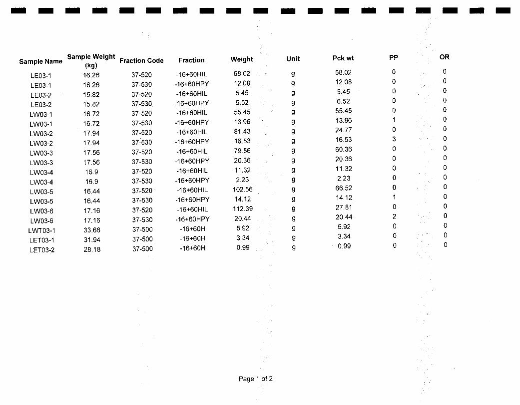
Weight
58.02
12.08
5.45 6.52
55.45 13.96 81.43
16.53
79.56
20.36
11.32
2.23 102.56
14.12
112.39
20.44
5.92 3.34
0.99
Pckwt
58.02 12.08
5.45 6.52 55.45
13.96 24.77 16.53
60.36 20.36
11.32
2.23
66.52 14.12
27.81
20.44 5.92
3.34
0.99
Unit
g
g
g g g g g
g
g g
g
g
g g
g
g g
g
g
PP
0 0
0 0 0 1
0 3
0
0
0 0
0 1
0
2
0 0
0
OR
0 0
0 0 0 0 0
0
0 0
0
0 0
0
0 0
0 0
0
- - - - - - - - - - - - - - - - - - -
Sample Weight Sample Name
(kg) Fraction Code Fraction
LE03-1 16.26 37-520 -16+60HIL
LE03-1 16.26 37-530 -16+60HPY
LE03-2 15.82 37-520 -16+60HIL
LE03-2 15.82 37-530 -16+60HPY
LW03-1 16.72 37-520 -16+60HIL
LW03-1 16.72 37-530 -16+60HPY
LW03-2 17.94 37-520 -16+60HIL
LW03-2 17.94 37-530 -16+60HPY
LW03-3 17.56 37-520 -16+60HIL
LW03-3 17.56 37-530 -16+60HPY
LW03-4 16.9 37-520 -16+60HIL
LW03-4 16.9 37-530 -16+60HPY
LW03-5 16.44 37-520 -16+60HIL
LW03-5 16.44 37-530 -16+60HPY
LW03-6 17.16 37-520 -16+60HIL
LW03-6 17.16 37-530 -16+60HPY
LWT03-1 33.68 37-500 -16+60H
LET03-1 31.94 37-500 -16+60H
LET03-2 28.18 37-500 -16+60H
Page 1 of 2
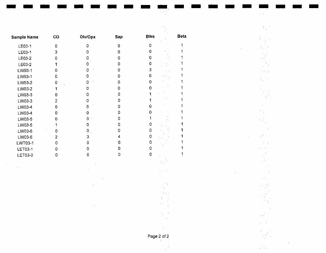
Sap
0
0 0
0
0 0
0
0
0
0
0
0 0 0 0 4
0 0 0
Biks
0
0
0
0
3 0
0
0 1
1
0
0 1
0
0
0 0
0 0
Beta
1
1 1
1
1 1
1
1 1
1
1
1
1 1
1
1 1
1 1
- - - - - - - - - - - - - - - - - - -
CD
0
3
0 1
0
0
0
1
0
2
0
0 0 1
0 2 0
0 0
Sample Name
LEO3-1
LEO3-1
LEO3-2
LEO3-2
LWO3-1
LWO3-1
LWO3-2
LWO3-2
LWO3-3
LWO3-3 LWO3-4
LWO3-4 LWO3-5 LWO3-5
LWO3-6
LWO3-6 LWTO3-1
LETO3-1
LETO3-2
OIv/Opx
0
0
0
0
0
0
0
0
0
0
0
0 0 0
0
3 0
0 0
Page 2 of 2

- - - - - - - - - - - - - - - - - -
Name Fraction Mount Cell Grain SA CFM DI Si02
LE03-1 -16+60HPY 4213 1 102 CE CP2 - 54.04
LE03-1 -16-'-60HPY 4213 1 103 CP CP2 52.67
LE03-2 -16+60HPY 4213 1 104 CP CPX - 53.65
LETO3-i *
* LETO3-2
LWO3-i -16+6OHIL
4213
1
106
PIL
LWO3-i -16+6OHIL
4213
1
201
PIL
LW03-1 -16+6OHIL
4213
1
202
PIL
LWO3-i .-16+6OHPY
4213
1
105
P
Gil-i
41.51
LWO3-2 -16-'-60HPY
4213
1
205
CE
CPX
54.63
LWO3-2 -16+6OHPY
4213
1
203
P
G9
41.79
LWO3-2 -16+6OHPY
4213
1
204
P
Gil-i
41.87
LWO3-2 -16+6OHPY
4213
1
206
P
Gil-i
41.85
LWO3-3 -1 6+6OHPY
4213
1
301
CE
CPX
54.18
LWO3-3 -16+6OHPY
4213
1
207
CP
CPX
54.31 *
LWO3-4
LWO3-5. -16+6OHIL
4213
1
305
CR
0
LWO3-5 -16+6OHPY
4213
1
304
CV
CP5
52.54
LWO3-5 -16+6OHPY
4213
1
303
P
Gil
41.08
LWO3-6 -16+6OHPY
4213
1
405
OLV-FORS
40.65
LWO3-6 -1 6+6OHPY
4213
1
406
OLV-FORS
41.14
LWO3-6 -1 6+6OHPY
4213
1
407
OLV-FORS
41.38
LWO3-6 -16+6OHPY
4213
1
403
CP
CP5
54.59
LWO3-6 -16+6OHPY
4213
1
404
CP
CPX
53.95
LWO3-6 -1 6+6OHPY
4213
1
402
P
G
42.1
LWO3-6 -16+6OHPY
4213
1
401
P
Gil
40.76 *
LWTO3-i
Page 1 of 3

- - - - - - - - - - - - - - - - - - -
Name Ti02 A1203 V203 Cr203 Fe203 FeO MgO CaO
LE03-1 0.03 1.16 0.38 5.17 15.03 22.6
LE03-1 0.11 2.51 0.94 4.96 16.71 20.58
LE03-2 0.2 1.92 1.23 3.37 16.69 21.49
LET03-1 LET03-2
LW03-1 51.79 0.58 0.41 9.65 24.97 12.32 0.01
LW03-1 52.34 0.66 0.5 9.16 22.79 13.87 0.02
LW03-1 52.28 0.62 0.44 8.62 24.59 12.79 0.02
LW03-1 0.17 19.75 5.37 7.79 19.2 5.29
LW03-2 0.02 1.21 0.39 3.49 16.14 23.04
LW03-2 0.03 22.28 2.34 9.39 18.46 4.98
LW03-2 0.19 19.93 5.32 7.09 19.41 5.57
LW03-2 0.03 19.52 5.99 7.15 19.19 5.76
LW03-3 0.04 1.15 0.48 4.86 15.79 22.32
LW03-3 0.03 0.82 0.58 : 3.94 16.01 23.17
LWO3-4 LW03-5 0.61 16.83 0.25 40.36 8.44 29.32 3.39 0
LW03-5 0.35 6.14 1.09 2.99 15.21 20.27
LW03-5 0.05 18.78 6.39 8.6 17.42 6.89
LW03-6 0.03 0 0 9.62 48.41 0.01
LW03-6 0.02 0 0.01 8.8 48.25 0.04
LW03-6 0.02 0.02 0 8.57 48.86 0.02
LW03-6 0.04 1.12 0.76 3.28 16.08 22.93
LW03-6 0.04 1.26 0.75 4.03 14.89 23.71
LW03-6 0.71 20.03 3.75 7.61 20.34 5.11
LW03-6 0.14 17.29 8.12 8.46 16.68 7.55
LWTO3-1
Page 2 of 3
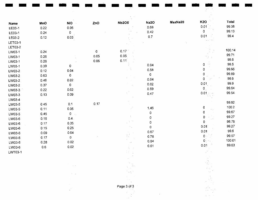
- - - - - - - - - - - - - - - - - - -
Name MnO NiO ZnO Nb205 Na20 MaxNa20 K20 Total
LE03-1 0.22 0.06 0.68 0.01 99.38
LE03-1 0.24 0 0.42 0 99.13
LE03-2 0.12 0.03 0.7 0.01 99.4
LET03-1
LET03-2
LW03-1
0.24
0
0.17
100.14
LW03-1
0.26
0.05
0.05
99.71
LW03-1
0.28
0.06
0.11
99.8
LWO3-1
0.39
0
0.04
0
99.5
LWO3-2
0.12
0.04
0.58
0
99.66
LWO3-2
0.63
0
0
0
99.89
LWO3-2
0.46
0.02
0.04
0
99.9
LWO3-2
0.37
0
0.02
0.01
99.9
LWO3-3
0.22
0.02
0.59
0
99.64
LWO3-3
0.13
0.09
0.47
0.01
99.54
LWO3-4
LWO3-5
0.45
0.1
0.17
99.92
LWO3-5
0.11
0.05
1.45
0
100.2
LWO3-5
0.45
0
0
0
99.67
LWO3-6
0.15
0.4
0
0
99.27
LWO3-6
0.17
0.35
0
0
98.78
LWO3-6
0.15
0.25
0
0.01•
99.27
LWO3-6
0.09
0.04
0.67
0.01
99.6
LWO3-6
0.17
0
0.78
0
99.57
LWO3-6
0.28
0.02
0.04
0
100.01
LWO3-6
0.6
0.02
0.01
0.01
99.63
LWTO3- 1
Page 3 of 3

I0 I -a
m z 0 ><
APPENDIX. 3 Airborne Geophysics I
I I I
977554 Alberta Ltd.
I ASSESSMENT REPORT
I
LEGEND PROSPECT
I
I I I I II II II II
Bob Ryziuk Geolink Exploration Ltd.
fl 10961 University Avenue Edmonton, Alberta T6G 1Y1
I II
977554 Alberta Ltd. 4700 - 888 3rd Street SW
Calgary, Alberta T21P 5C5
I I FUGRO ARBORNESURVEYS
I I I I I I I I I I II LI I I
Fugro Airborne Surveys Corp.
IMississauga, Ontario
January 19, 2004
'I I'
RESOLVE SURVEY FOR
977554 ALBERTA LTD.
FT. MCMURRAY AREA, AB
—fn
Report #03094
Michael J. Cain Geophysicist

SUMMARY
This report describes the logistics, data acquisition and processing of a RESOLVE airborne
geophysical survey carried out for 977554 Alberta Ltd., over the Ft McMurray area, Alberta.
Total coverage of the survey blocks amounted to 83 km. The survey was flown on
December 31, 2003.
The purpose of the survey was to detect kimberlite targets. This was accomplished by
using a RESOLVE multi-coil, multi-frequency electromagnetic system, supplemented by two
high sensitivity cesium magnetometers in a horizontal gradiometer configuration. The
information from these sensors was processed to produce maps that display the magnetic
and conductive properties of the survey area. A GPS electronic navigation system ensured
accurate positioning of the geophysical data with respect to the base maps.
The survey data were processed and compiled in the Fugro Airborne Surveys Toronto
office. Map products and digital data were provided in accordance with the scales and
formats specified in the Survey Agreement.
I I I I I I I I I I I U I II I I I II II

CONTENTS
1.
INTRODUCTION ............................... .................. ................................. .................................. .: 1.1
2. SURVEY OPERATIONS ................................................................................................ 2 . 1
3. SURVEY EQUIPMENT .................................................................................................. 3 . 1
ElectromagneticSystem................................................................................................. 3 . 1 RESOLVE System Calibration .......................................................................................3. 2 AirborneMagnetometer.................................................................................................. 3 . 4
MagneticBase Station ................................................................................................... 3 . 4 Navigation (Global Positioning System) .........................................................................3.6 RadarAltimeter .............................................................................................................. 3 . 7 Barometric Pressure and Temperature Sensors............................................................3.8 LaserAltimeter............................................................................................................... 3 . 8
AnalogRecorder ............................................................................................................ 3 . 9
Digital Data Acquisition System ...................................................................................... 3 . 9 Flight Path Video Recording System ....................................................................... ....... 3.9
4 QUALITY CONTROL AND IN-FIELD PROCESSING 4.1
5. DATA PROCESSING..................................................................................................... 5 . 1
FlightPath Recovery...................................................................................................... 5 . 1
Electromagnetic Data/Apparent Resistivity ....................................................................5.1 TotalMagnetic Field....................................................................................................... 5 . 3 Contour, Colour and Shadow Map Displays ..................................................................5. 4
Resistivity-depth Sections .............................................................................................. 5 . 5
6. Discussion...................................................................................................................... 6 . 1
KimberliteSignatures ..................................................................................................... 6 . 1
7. PRODUCTS ................................................................................................................... 7 . 1
BaseMaps ..................................................................................................................... 7 . 1
FinalProducts ................................................................................................................ 7 . 2
8. CONCLUSIONS AND RECOMMENDATIONS ..............................................................8.1
I I I I I I I I I I I I II II I I II II II

I I I
APPENDICES
I I
A. List of Personnel B. Optional Products C. Background Information D. Data Archive Description
I I I I I I I I I I II I I II

I I
-1.1 -
I 1. INTRODUCTION
I I
A RESOLVE electromagnetic/resistivity/magnetic survey was flown for 977554 Alberta Ltd.
on December 31, 2003, over the Ft McMurray area, Alberta.
I I I I I I I I I I 11
Survey coverage consisted of 83 line-km, over 7 blocks. Flight lines were flown in an
azimuthal direction of 900 with a line separation of 50 metres. A single tie line was flown
perpendicular to the survey lines on all blocks except the Legend block.
The survey employed the RESOLVE electromagnetic system. Ancillary equipment
consisted of a horizontal magnetic gradiometer radar laser and barometric altimeters
video camera, analog and digital recorders, and an electronic navigation system. The
instrumentation was installed in an A5350-BA turbine helicopter (Registration C-GJ1X) that
was provided by Questral Helicopters Ltd. The helicopter flew at an average airspeed of
135 km/h with an EM sensor height of approximately 35 metres.
I II II

-1.2-
Figure 1: Fugro Airborne Surveys RESOLVE EM bird with AS350-B3
I I I I I I I I I I I I I I I I I I II

Parameter Specifications
Traverse line direction 90 11/270° Traverse line spacing 50 m Tie line direction 0 11/180" Tie line spacing - Sample interval 10 Hz or 3.8 m at 135 km/hr Aircraft mean terrain clearance 62 m EM sensor mean terrain clearance 35 m Mag sensor mean terrain clearance 35 m Average speed 135 km/hr Navigation (guidance) ±5 m, Real-time GPS Post-survey flight path ±2 m, Differential GPS
I I I I I I I I I I I I I 1 I II II I II
2. SURVEY OPERATIONS
The base of operations for the survey was established at Legend camp, Alberta. The
survey was flown from on December 31, 2003 over seven survey blocks. The survey
area can be located on NTS map sheets 84A113,16; 84H/1,2 (Figure 2).
Total survey coverage consisted of-83 line-km
The survey specifications were as follows:

57OON
LOCATION MAP 11330W
I I 1 1 I I I I I I I I
II III III I I II
- 2.2 -
NTS: 84A/13 UTM ZONE: 12 SCALE: 1:250.000
NAD27
Figure 2a Location Map and Sheet Layout
Target A and Target B Ft McMurray Area
Job # 03094

- 2.3 -
LOCATION MAP
TOON
NTS: 84A/16 UTU ZONE: 12 SCALE: 1:250.000
NAD27
II 11 I I II II II II II II II m III II 11 UI II II H
Figure 2b Location Map and Sheet Layout Target 1, Target 3 and Target 4
Ft McMurray Area Job # 03094
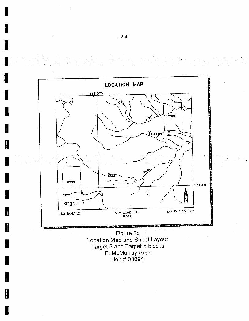
LOCATION MAP
NTS: 84H/1.2 UTM ZONE: 12 SCALE: 1:250.000
NA027
5700N
I I I II II 'I II II II n II II III III I Ii II II II
- 2.4 -
Figure 2c Location Map and Sheet Layout
Target 3 and Target 5 blocks Ft McMurray Area
Job # 03094

I I I I' I I I I I I I I II II I I I II I
- 2.5 -
LOCATION MAP I 13'OUW
5T00'N
SCALE: 1:250.000
Figure 2d Location Map and Sheet Layout
Target 3 and Legend blocks Ft McMurray Area
Job # 03094
NIS: 84H/2 U1M ZONE: 12 NA027

I I
3. SURVEY EQUIPMENT
This section provides a brief description of the geophysical instruments used to acquire the
survey data and the calibration procedures employed. The geophysical equipment was
installed in an AS350-BA helicopter. This aircraft provides a safe and efficient platform for
surveys of this type.
Electromagnetic System
RESOLVE
Towed bird, symmetric dipole configuration operated at a nominal survey altitude of 30 metres. Coil separation is 79 metres for 400 Hz, 1500 Hz, 6400 Hz, 25,000 Hz and 115,000 Hz coplanar coil-pairs; and 9.0 metres for the 3300 Hz coaxial coil-pair.
Coil orientations/frequencies: orientation nominal actual
coplanar 400 Hz 389 Hz coplanar 1500 Hzl 574 Hz coaxial 3300 Hz 3245 Hz
coplanar 6400 Hz6075 Hz coplanar 25,000 Hz25,300 Hz coplanar 115,000 Hz114,940 Hz
Channels recorded: 6 in-phase channels 6 quadrature channels 2 monitor channels
0.12 ppm at 400 HzCP 0.12 ppm at 1500 Hz CP 0.12 ppm at 3300 Hz CX 0.24 ppm at 6400 Hz CP 0.60 ppm at 25,000 Hz CP 0.60 ppm at 115,000 Hz CP
10 per second, equivalent to 1 sample every 3.8 m, at survey speed of 135 km/h.
I I I I I I I I I I I II I 'I II II II
Model
Type:
Sensitivity:
Sample rate:

I I
- 3.2 -
The electromagnetic system utilizes a multi-coil coaxial/coplanar technique to energize
conductors in different directions The coaxial coils are vertcaI with their axes in the flight
direction. The coplanar coils are horizontal. The secondary fields are sensed
simultaneously by means of receiver coils that are maximum coupled to their respective
transmitter coils. The system yields an in-phase and a quadrature channel from each
transmitter-receiver coil-pair.
RESOLVE System Calibration
I
Calibration of the system during the survey uses the Fugro AutoCal automatic, internal
calibration process. At the beginning and end of each flight, and at intervals during the
I flight, the system is flown up to high altitude to remove it from any "ground effect"
(response from the earth). Any remaining signal from the receiver coils (base level) is
measured as the zero level, and removed from the data collected until the time of the
next calibration. Following the zero level setting, internal calibration coils, for which the
response phase and amplitude have been determined at the factory, are automatically
triggered - one for each frequency. The on-time of the coils is sufficient to determine an
accurate response through any ambient noise. The receiver response to each
calibration coil "event" is compared to the expected response (from the factory
calibration) for both phase angle and amplitude, and the applied phase and gain
corrections are adjusted to bring the data to the correct value. In addition, the output of
the transmitter coils are continuously monitored during the survey, and the applied gains
adjusted to correct for any change in transmitter output.
I II
I I I I I I
I I I I I I I
I I I I I
- 3.3 -
Because the internal calibration coils are calibrated at the factory (on a resistive
halfspace) ground calibrations using external calibration coils on-site are not necessary
for system calibration. A check calibration may be carried out on-site to ensure all
systems are working correctly. All system calibrations will be carried out in the air, at
I sufficient altitude that there will be no measurable response from the ground.
The internal calibration coils are rigidly positioned and mounted in the system relative to
the transmitter and receiver coils. In addition, when the internal calibration coils are
calibrated at the factory, a rigid jig is employed to ensure accurate response from the
external coils.
Using real time Fast Fourier Transforms and the calibration procedures outlined above,
the data will be processed in real time from measured total field at a high sampling rate
to in-phase and quadrature values at 10 samples per second.
U
I I I I I I I I I I II I II

I I I I I I I I I I I I I I I I I I I
- 3.4 -
Airborne Magnetometer
Configuration: Horizontal Gradiometer
Model: Fugro AM1 02 processor with two Scintrex CS2 sensors
Type: Optically pumped cesium vapour
Sensitivity: 0.01 nT
Sample rate: 10 per second
The horizontal gradiometer consists of two high sensitivity cesium sensors housed in a
transverse mounted rigid boom at the rear of the HEM bird. The sensor separation is 5
m and is flown 27 m below the helicopter.
Magnetic Base Station
Primary
Model: Fugro CF1 base station with timing provided by integrated GPS
Sensor type: Geometrics G822
Counter specifications: Accuracy: ±0.1 nT Resolution: 0.01 nT Sample rate 1 Hz
GPS specifications: Model: Marconi Allstar Type: Code and carrier tracking of Li band,
12-channel, C/A code at 1575.42 MHz Sensitivity: -90 dBm, 1.0 second update Accuracy: Manufacturer's stated accuracy for differential
corrected GPS is 2 metres

- 3.5 -
Environmental Monitor specifications: Temperature:
• Accuracy ±1.50C max • Resolution: 0.0305°C • Sample rate: 1 Hz • Range: -40°C to +75°C
Barometric pressure: • Model: Motorola MPXA41 1 5A • Accuracy: ±3.00 kPa max (-20°C to 105°C temp. ranges) • Resolution: 0.013 kPa • Sample rate: 1 Hz • Range: 55kPato108kPa
Backup Magnetometer
Model: GEM Systems GSM-19T
Type: Digital recording proton precession
Sensitivity: 0.10 nT
Sample rate: 3 second intervals
A digital recorder is operated in conjunction with the base station magnetometer to record
the diurnal variations of the earth's magnetic field. The clock of the base station is
synchronized with that of the airborne system, using GPS time, to permit subsequent
removal of diurnal drift.
I I I I I I I I I I I I I I I I II II II

- 3.6 -
Navigation (Global Positioning System)
Airborne Receiver for Real-time Navigation & Guidance
Model: Ashtech Glonass GG24 with PNAV 2100 interface
Type: SPS (Li band), 24-channel, C/A code at 1575.42 MHz, S code at 0.5625 MHz, Real-time differential.
Sensitivity: -132 dBm, 0.5 second update
Accuracy: Manufacturer's stated accuracy is better than 5 metres real-time
The antenna for the GPS guidance system is mounted on the tail fin of the helicopter.
Airborne Receiver for Flight Path Recovery
Model: Ashtech Dual Frequency Z-Surveyor
Type: Code and carrier tracking of Li band, 12-channel, dual frequency C/A code at 1575.2 MHz, and L2 P-code 1227 MHz
Sensitivity: 0.5 second update
Accuracy: Manufacturer's stated accuracy for differential corrected GPS is better than 1 metre
The antenna for the GPS flight path recovery system is housed on the rear of the EM bird.
Primary Base Station for Post-Survey Differential Correction
Model: Ashtech Dual Frequency Z-Surveyor
Type: Code and carrier tracking of Li band, 12-channel, dual frequency C/A code at 1575.2 MHz, and L2 P-code 1227 MHz
Sensitivity: 1.0 second update
Accuracy: Manufacturer's stated accuracy for differential corrected GPS is better than 1 metre
I I I I I I I I I I U I I II II I I II II

- 3.7 -
Secondary GPS Base Station
Model: Marconi Alistar OEM, CMT-i 200
Type: Code and carrier tracking of Li band, 12-channel, C/A code at 1575.42 MHz
Sensitivity: -90 dBm, 1.0 second update
Accuracy: Manufacturer's stated accuracy for differential corrected GPS is 2 metres.
The Ashtech GG24 is a line of sight, satellite navigation system that utilizes time-coded
signals from at least four of forty-eight available satellites. Both Russian GLONASS and
American NAVSTAR satellite constellations are used to calculate the position and to
provide real time guidance to the helicopter. For flight path processing an Ashtech Z-
surveyor was used as the mobile receiver. A similar system was used as the primary base
station receiver. The mobile and base station raw XYZ data were recorded, thereby
permitting post-survey differential corrections for theoretical accuracies of better than 2
metres. A Marconi Alistar GPS unit was used as a secondary (back-up) base station.
Radar Altimeter
Manufacturer: Honeywell/Sperry
Model: RT330
Type: Short pulse modulation, 4.3 GHz
Sensitivity: 0.3 m
I I I I I F I I I I I I II 1 I II I I II
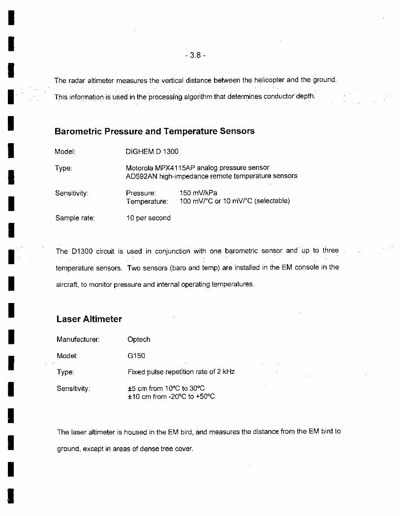
I I
- 3.8 -
I The radar altimeter measures the vertical distance between the helicopter and the ground.
I
This information is used in the processing algorithm that determines conductor depth
I Barometric Pressure and Temperature Sensors
I I I I I I I I I I I I
Model:
Type:
Sensitivity:
Sample rate
DIGHEM D 1300
Motorola MPX41 1 5AP analog pressure sensor AD592AN high-impedance remote temperature sensors
Pressure: 150 mV/kPa Temperature: 100 mV/°C or 10 mV/°C (selectable)
10 per second
The D1300 circuit is used in conjunction with one barometric sensor and up to three
temperature sensors. Two sensors (baro and temp) are installed in the EM console in the
aircraft, to monitor pressure and internal operating temperatures.
Laser Altimeter
Manufacturer:
Model:
Type:
Sensitivity:
Optech
G150
Fixed pulse repetition rate of 2 kHz
±5 cm from 10°C to 30°C ±10 cm from -20°C to +50°C
The laser altimeter is housed in the EM bird, and measures the distance from the EM bird to
ground, except in areas of dense tree cover.
I I

I I I I I I I I I I I I I I I I I I I
- 3.9 -
Analog Recorder
Manufacturer: RMS Instruments
Type: DGR33 dot-matrix graphics recorder
Resolution: 44 dots/mm
Speed: 1.5mm/sec
The analog profiles are recorded on chart paper in the aircraft during the survey. Table
3-1 lists the geophysical data channels and the vertical scale of each profile.
Digital Data Acquisition System
Manufacturer: RMS Instruments
Model: DGR 33
Recorder: San Disk compact flash card (PCMCIA)
The data are stored on flash cards and are downloaded to the field workstation PC at the
survey base for verification, backup and preparation of in-field products.
Flight Path Video Recording System
Recorder: Panasonic AG-720

1 I I
Fiducial numbers are recorded continuously and are displayed on the margin of each
I image This procedure ensures accurate correlation of analog and digital data with respect
I to visible features on the ground.
I I I I I I I 1 I I I I I
Table 3-1. The Analog Profiles
Channel Scale Name Parameter units/mm
4001 coaxial in-phase ( 400 Hz) 5 ppm 400Q coaxial quad ( 400Hz) 5 ppm 1 K51 coplanar in-phase ( 1500 Hz) 5 ppm 1 K5 coplanar quad ( 1500 Hz) 5 ppm 1 X8 coaxial in-phase ( 3300 Hz) 5 ppm 1 X8 coaxial quad ( 3300 Hz) 5 ppm 6K21 coplanar in-phase ( 6200 Hz) 10 ppm 6K2Q coplanar quad 6200 Hz) 10 ppm 25K1 coplanar in-phase ( 25,000 Hz) 40 ppm 25KQ coplanar quad ( 25,000 Hz) 40 ppm 1001 coplanar inphase (115,000 Hz) 40 ppm 100Q coplanar quad (115,000 Hz) 40 ppm ALTL altimeter (laser) 3 m ALTR altimeter (radar) 3 m MAG1 magnetics, coarse 20 nT 1 SP coaxial spherics monitor 25P coplanar spherics monitor 2PL coplanar powerline monitor 1 KPA altimeter (barometric) 30 m 2TDC internal (console) temperature .10 C 3TDC external temperature 10 C
I

-4.1 -
4. QUALITY CONTROL AND IN-FIELD PROCESSING
Digital data for each flight were transferred to the field workstation, in order to verify data
quality and completeness. A database was created and updated using Geosoft Oasis
Montaj and proprietary Fugro Atlas software. This allowed the field personnel to
calculate, display and verify both the positional (flight path) and geophysical data on a
screen or printer. Analog records were examined as a preliminary assessment of the
data acquired for each flight.
In-field processing of Fugro survey data consists of differential corrections to the
airborne GPS data verification of EM calibrations drift correction of the raw airborne EM
data, spike rejection and filtering of all geophysical and ancillary data, verification of
flight videos, calculation of preliminary resistivity data, diurnal correction, and preliminary
leveling of magnetic data.
All data, including base station records, were checked on a daily basis, to ensure
compliance with the survey contract specifications. Reflights were required if any of the
standard specifications were not met.
I I I I I I I I I I I I I I I I I I I

I I I
5. DATA PROCESSING
I I
Flight Path Recovery
The raw range data from at least four satellites are simultaneously recorded by both the
base and mobile GPS units. The geographic positions of both units, relative to the
model ellipsoid, are calculated from this information. Differential corrections, which are
obtained from the base station, are applied to the mobile unit data to provide a post-flight
track of the aircraft, accurate to within 2 m. Speed checks of the flight path are also
carried out to determine if there are any spikes or gaps in the data.
The corrected WG584 latitude/longitude coordinates are transformed to the coordinate
system used on the final maps. Images or plots are then created to provide a visual
check of the flight path.
Electromagnetic Data/Apparent Resistivity
EM data are processed at the recorded sample rate of 10 samples/second. Spheric
rejection median and Hanning filters were applied to reduce noise to acceptable levels.
The apparent resistivity in ohm-m were generated from the in-phase and quadrature EM
components for all of the coplanar frequencies, using a pseudo-layer half-space model.
The inputs to the resistivity algorithm are the inphase and quadrature amplitudes of the
secondary field. The algorithm calculates the apparent resistivity in ohm-m, and the
apparent height of the bird above the conductive source. Any difference between the
a I I I I I I I I I a I I I
I I
- 5.2 -
apparent height and the true height, as measured by the radar altimeter, is called the
pseudo-layer and reflects the difference between the real geology and a homogeneous
halfspace. This difference is often attributed to the presence of a highly resistive upper
layer. Any errors in the altimeter reading, caused by heavy tree cover, are included in the
pseudo-layer and do not affect the resistivity calculation. The apparent depth estimates,
however, will reflect the altimeter errors. Apparent resistivity calculated in this manner may
behave quite differently from those calculated using other models.
In areas of high magnetic permeability or dielectric permittivity, the calculated resistivities
will be erroneously high. Various algorithms and inversion techniques can be used to
partially correct for this effect.
The preliminary apparent resistivity maps and images were carefully inspected to identify
any lines or line segments that might require base level adjustments. Subtle changes
between in-flight calibrations of the system can result in line-to-line differences that are more
recognizable in resistive (low signal amplitude) areas. Manual leveling was carried out to
eliminate or minimize resistivity differences that can be attributed, in part, to changes in
operating temperatures. These leveling adjustments were usually very subtle, and do not
result in the degradation of discrete anomalies.
I After the manual leveling process is complete, the data were subjected to a microleveling
technique in order to remove any remaining line-to-line differences within the calculated
I I
I I I I I I I I 1 I I I I
I

1 I
- 5.3 -
I Apparent resistivity grids, which display the conductive properties of the survey areas, were
I produced from the 400 Hz 1500 Hz 6400 Hz 25,000 Hz and 115,000 Hz coplanar data
The calculated resistivities for the five coplanar frequencies are included in the XYZ and grid
archives. Values are in ohm-metres on all final products.
Total Magnetic Field
The aeromagnetic data were inspected in grid and profile format. Spikes were removed
manually with the aid of a fourth difference calculation. A Geometrics G822 cesium
vapour magnetometer was operated at the survey base to record diurnal variations of
the earth's magnetic field The clock of the base station was synchronized with that of
the airborne system to permit subsequent removal of diurnal drift. The data were
inspected for spikes and filtered. The filtered diurnal data were subtracted from the total
field magnetic data. Grids of the diurnally corrected aeromagnetic data were created
and contoured. A lag correction was applied to the magnetic data. The results were
then leveled using tie and traverse line intercepts. Manual adjustments were applied to
any lines that required leveling, as indicated by shadowed images of both the total field
magnetic data and the calculated vertical gradient data. A microleveling algorithm was
used to make any remaining subtle leveling adjustments.
I I I
I I I I I a I I I I
I

I I I
- 5.4 -
Contour, Colour and Shadow Map Displays
I The geophysical data are interpolated onto a regular grid using a modified Akima spline
I technique. The resulting grid is suitable for image processing and generation of contour
maps. The grid cell size was 10 metres or 20% of the line interval.
I Colour maps are produced by interpolating the grid down to the pixel size. The parameter is
I
then incremented with respect to specific amplitude ranges to provide colour "contour"
I maps.
I
The colour distribution used for the differential resistivity maps was selected to cover the
resistivity range of all the target blocks. The same distribution was used for all maps to
I allow easy visual comparison; each colour on the scale represents the same resistivity
I value on all maps. The total magnetic field distribution was generated to cover the magnetic
intensity for each individual block.
I Monochromatic shadow maps or images can be generated by employing an artificial sun to
cast shadows on a surface defined by the geophysical grid. There are many variations in
the shadowing technique. These techniques can be applied to total field or enhanced
magnetic data, magnetic derivatives, resistivity, etc. The shadowing technique is also used
as a quality control method to detect subtle changes between sines.
I I
I I I
I

U I I
- 5.5 -
Resistivity-depth Sections
The apparent resistivities for all frequencies can be displayed simultaneously as coloured
resistivity-depth sections: Usually, only the coplanar data are displayed as the close
frequency separation between the coplanar and adjacent coaxial data tends to distort the
section. The sections can be plotted using the topographic elevation profile as the surface.
The digital terrain values, in metres a.m.s.l., can be calculated from the GPS Z-value or
barometric altimeter, minus the aircraft radar altimeter.
Resistivity-depth sections can be generated in three formats:
(1) Sengpiel resistivity sections, where the apparent resistivity for each frequency is
plotted at the depth of the centroid of the in-phase current flow'; and
(2) Differential resistivity sections, where the differential resistivity is plotted at the
differential depth 2 .
(3) Occam 3 or Multi-layer4 inversion.
Both the Sengpiel and differential methods are derived from the pseudo-layer half-space
model. Both yield a coloured resistivity-depth section that attempts to portray a smoothed
approximation of the true resistivity distribution with depth. Resistivity-depth sections are
most useful in conductive layered situations, but may be unreliable in areas of moderate to
high resistivity where signal amplitudes are weak. In areas where in-phase responses have
1 Sengpiel, K.P., 1988, Approximate Inversion of Airborne EM Data from Multilayered Ground: Geophysical Prospecting 36, 446-459. 2 Huang, H. and Fraser, DC., 1993, Differential Resistivity Method for Multi-frequency Airborne EM Sounding: presented at Intern. Airb. EM Workshop, Tucson, Ariz.
Constable et al, 1987, Occam's inversion: a practical algorithm for generating smooth models from electromagnetic sounding data: Geophysics, 52, 289-300.
Huang H., and Palacky, G.J., 1991, Damped least-squares inversion of time domain airborne EM data based on singular value decomposition: Geophysical Prospecting, 39, 827-844.
I I I I I
I I I I I I I II II

I I
- 5.6 -
I been suppressed by the effects of magnetite, or adversely affected by cultural features, the
I computed resistivities shown on the sections maybe unreliable
I Both the Occam and multi-layer inversions compute the layered earth resistivity model that
I
would best match the measured EM data. The Occam inversion uses a series of thin, fixed
layers (usually 20 x 5m and 10 x 1 O layers) and computes resistivities to fit the EM data.
I The multi-layer inversion computes the resistivity and thickness for each of a defined
I number of layers (typically 3-5 layers) to best fit the data.
I I I I I I I I I I I
U I I
6. Discussion
I I
Kimberlite Signatures
In plan view, kimberlite pipes are usually circular or oblate, and can often be elongated with
the long axis parallel to and/or coincident with structural lineations. These zones of
structural weakness often control or influence the emplacement of kimberlitic material.
Unweathered kimberlites can contain up to 10% magnetic oxides (magnetite, ilmenite) and,
as a result, can often produce a strong magnetic response. However, moderate to strong
magnetic lows, due to rernanent magnetization, are also observed over some kimberlites.
In some cases, the magnetic responses can be very weak, and may not be easily
recognized in areas of moderate to steep magnetic gradients.
Kimberlites weather relatively rapidly because of their high porosity and permeability. The
crater facies weathers to a conductive, clay-rich material with a lower magnetic mineral
content than the unweathered source. The top of a weathered pipe assumes a flat-lying
disc shape that can be several tens of metres in thickness.
The preferential weathering of kimberlitic material, relative to the surrounding country rock,
often results in topographic depressions that form small, circular lakes. In many cases, the
shapes of these lakes closely resemble the shapes of the resistivity and/or magnetic
anomalies.
I I I I I I I U I I I I I I

I I
-6.2-
The geophysical signature over a weathered pipe generally comprises a circular to elliptical
conductivity response that is often coincident with a similarly shaped magnetic anomaly.
The primary source of the magnetic response is the lower, unweathered portion of the pipe,
while the primary source for the conductive response is the upper, weathered portion.
Weathered tops will generally produce a stronger conductivity response while unweathered
portions will produce a stronger magnetic response. A typical EM response over a
horizontal disk (clay-weathered top) is given in Figure 7-1.
The weakly conductive lake-bottom material underlying the lakes, gives rise to resistivity
values that are generally less than 5000 ohm-m. As weathered kimberlites often yield
resistivities in the 500 ohm-m to 3000 ohm-m range, the contrasts within the lake areas may
be subtle. In some cases, the lake-bottorn material may be thick enough to mask some of
the weaker, underlying bedrock sources.
I I I I I I I I I I I I I I

I I
-6.3-
I I
Figure 6-1
I Response from a horizontal disk
I I I I I I I I I I I I I I
DISK 00
(horizontal)
From: Greinwald, S., Fraser, D.C., Report on Model Studies with Numerical Dipole Models, December 31, 1974.
I I
- 6.4 -
The differences in the geophysical response shapes from lake-bottom sediments and the
clay-weathered tops of pipes are also very subtle and can be difficult to resolve particularty
when the surface area of the pipe becomes large enough or thick enough to approach a
halfspace model. In such cases, there may be no "discrete" EM anomaly on the coaxial
parameter, although the maximum coupled coplanar response should yield an
anomalous resistivity low. The differentiation of kimberlite responses from sake-bottom
material is based on 6 main criteria:
• the conductivity (resistivity) of the anomalous feature;
• the EM response characteristics;
• the apparent depth (and extent) of the causative source;
the plan shape and dimensions of the resistivity low;
o the coincidence of either a positive or negative magnetic anomaly; and
the proximity to dykes or other structural features.
I I The geophysical detection of pipes requires a measurable physical contrast with the
surrounding material. Since pipes can be emplaced in virtually any kind of rock, the
I contrast depends on both the pipe and host rock lithologies as well as the overburden
I material. Kimberlite pipes will dominate the geophysical response in resistive, magnetically
inactive host rocks, whereas they can be virtually indistinguishable in conductive,
I magnetically active areas.
I I
I I I I I I I
I
7. PRODUCTS
This section lists the final maps and products that have been provided under the terms
of the survey agreement. Other products can be prepared from the existing dataset, if
requested. These include magnetic enhancements or derivatives, percent magnetite,
resistivities corrected for magnetic permeability and/or dielectric permittivity, digital
terrain, resistivity-depth sections, inversions, and overburden thickness.
Base Maps
Base maps of the survey area were produced by scanning published topographic maps
to a bitmap (bmp) format...This process provides a relatively, accurate distortion free
base that facilitates correlation of the navigation data to the map coordinate system.
The topographic files were combined with geophysical data for plotting the final maps.
All maps were created using the following parameters:
Projection Description:
Datum:
NAD 27 Ellipsoid:
Clarke 1866 DX,DY,ZY shift
7, -162, -188 Projection:
UTM (Zone: 12) Central Meridian:
111° West False Northing:
0 False Easting:
500000 Scale Factor:
0.9996
I I I I I I I I I I I I I I I I I I I

- 7.2-
The following parameters are presented on 1 map sheet for each target, at a scale of
1:10,000. All maps include flight lines and topography. Preliminary products are not listed.
Final Products
Colour Maps (2 copies) at 1:10000
Total Magnetic Field maps Differential Resistivity 400 Hz Differential Resistivity 1 500 Hz Differential Resistivity 6200 Hz Differential Resistivity 25,000 Hz Differential Resistivity 115,000 Hz
Additional Products
Differential Depth Sections Digital Archive on CD-ROM Survey Report Analog Chart Records Flight Path Video (VHS)
2 sets 2 copies 2 copies All flights 1 video cassette

0
0 -8.1 -
U 8. CONCLUSIONS AND RECOMMENDATIONS
U This report provides a description of the equipment, data processing procedures and
logistics of the survey.
U The various maps included with this report display the magnetic and conductive properties
of the survey area It is recommended that a complete assessment and detailed evaluation
of the survey results be carried out in conjunction with all available geophysical, geological
and geochemical information.
U It is also recommended that image processing of existing geophysical data be considered,
in order to extract the maximum amount of information from the survey results Current
software and imaging techniques often provide valuable information on structure and
lithology, which may not be clearly evident on the contour and colour maps. These
techniques can yield images that define subtle, but significant, structural details
U Respectfully submitted,
U FLJGRO AIRBORNE SURVEYS CORP.
U Michael Cain Geophysicist
U
U
I
APPENDIX A LIST OF PERSONNEL
The foLlowing personnel were involved in the acquisition, processing, interpretation and presentation of data, relating to a RESOLVE airborne geophysical survey carried out for 977554 Alberta Ltd over the Ft McMurray area, Alberta
David Mites Emily Farquhar Michael Cain Will Man Igor Siam Michel Plourde Lyn Vandeistarren Albina Tonello
Manager, Helicopter Operations Manager, Data Processing and Interpretation Project Geophysicist Geophysical Operator Field Geophysicist Pilot (Questral Helicopters Ltd.) Drafting Supervisor Secretary/Expeditor
The survey consisted of 83 km of coverage, flown on December 31 2003-
All personnel are employees of Fugro Airborne Surveys, except for the pilot who is an employee of Questial Helicopters Ltd.

I I I
APPENDIX B OPTIONAL PRODUCTS
I , Digital Terrain
I I
The radar altimeter values (ALTR - aircraft to ground clearance) are subtracted from the
differentially corrected and de-spiked GPS-Z values to produce profiles of the height
above the ellipsoid along the survey lines. These values are gridded to produce contour
maps showing approximate elevations within the survey area. The calculated digital
terrain data are then tie-line leveled and adjusted to mean sea level. Any remaining
I subtle line-to-line discrepancies are manually removed. After the manual corrections are
applied, the digital terrain data are filtered with a microleveling algorithm.
I The accuracy of the elevation calculation is directly dependent on the accuracy of the
two input parameters, ALTR and GPS-Z. The ALTR value may be erroneous in areas of
Iheavy tree cover, where the altimeter reflects the distance to the tree canopy rather than
the ground. The GPS-Z value is primarily dependent on the number of available
I satellites. Although post-processing of GPS data will yield X and Y accuracies in the
I order of 1-2 metres, the accuracy of the Z value is usually much less, sometimes in the
±10 metre range. Further inaccuracies may be introduced during the interpolation and
gridding process.
Because of the inherent inaccuracies of this method, no guarantee is made or implied
that the information displayed is a true representation of the height above sea level.
Although this product may be of some use as a general reference, THIS PRODUCT
MUST NOT BE USED FOR NAVIGATION PURPOSES.
I I
I I I I I

- Appendix B.2-
I I H
Dielectric Permittivity and Magnetic Permeability Corrections'
I In resistive areas having magnetic rocks, the magnetic and dielectric effects will both
I generally be present in high-frequency EM data, whereas only the magnetic effect will
exist in low-frequency data.
I I
The magnetic permeability is first obtained from the EM data at the lowest frequency
(385 Hz) because the ratio of the magnetic response to conductive response is
maximized and because displacement currents are negligible. The homogeneous half-
space model is used. The computed magnetic permeability is then used along with the
inphase and quadrature response at the highest frequency to obtain the relative
dielectric permittivity, again using the homogeneous half-space model. The highest
frequency is used because the ratio of dielectric response to conductive response is
maximized. The resistivity can then be determined from the measured inphase and
quadrature components of each frequency, given the relative magnetic permeability and
relative dielectric permittivity.
Horizontal Gradient Enhanced Total Magnetic Field
I Bidirectional gridding with the cross-line gradient should produce a surface that correctly
renders both the measured data and the measured horizontal gradient at each survey
I I
I I
I I I I I I I
I

- Appendix B.3 -
I I
line. This can be an advantage when gridding data that include features approaching
the line separation in size and also for rendering features that are not perpendicular to
I the line direction, particularly those which are sub-parallel to the line direction. Direct
I results of the application of Horizontal Gradient Enhanced (HGE) gridding are:
. Increased resolution and continuity of magnetic features parallel or sub-parallel
I
to the flight line direction.
• Correct spatial positioning of finite source magnetic bodies between lines.
I • Improved resolution of analytical signal and enhanced analytic signal products.
I I
Calculated Vertical Magnetic Gradient
The horizontal gradient enhanced total magnetic field data were subjected to a processing
algorithm that enhances the response of magnetic bodies in the upper 500 m and
attenuates the response of deeper bodies. The resulting vertical gradient map provides
better definition and resolution of near-surface magnetic units. It also identifies weak
magnetic features that may not be evident on the total field map. However, regional
magnetic variations and changes in lithology may be better defined on the total magnetic
field map.
Multi-channel Stacked Profiles
Distance-based profiles of the digitally recorded geophysical data can be generated and
plotted at an appropriate scale. These profiles also contain the calculated parameters that
Huang, H. and Fraser, D.C., 2001 Mapping of the Resistivity, Susceptibility, and Permittivity of
I I I I I I I I I I 1

- Appendix B.4 -
are used in the interpretation process. These are produced as worksheets prior to
interpretation, and are also presented in the final corrected form after interpretation.
EM Magnetite
The apparent percent magnetite by weight is computed wherever magnetite produces a
negative in-phase EM response. This calculation is more meaningful in resistive areas.
Magnetic Derivatives
The total magnetic field data can be subjected to a variety of filtering techniques to yield
maps or images of the following:
enhanced magnetics
second vertical derivative
reduction to the pole/equator
magnetic susceptibility with reduction to the pole
upward/downward continuations
analytic signal
All of these filtering techniques improve the recognition of near-surface magnetic bodies,
with the exception of upward continuation. Any of these parameters can be produced on
request.
the Earth Using a Helicopter-borne Electromagnetic System: Geophysics 106 pg 148-157.
I I I I I I I I I I I
I I I I I I I I

I I
- Appendix B.5 -
I I I I I I I I I I I I I 1 I I I

I I
-Appendix C.1 -
I APPENDIX C
I BACKGROUND INFORMATION
Electromagnetics
I Fugro electromagnetic responses fall into two general classes, discrete and broad. The
I discrete class consists of sharp, well-defined anomalies from discrete conductors such as sulphide lenses and steeply dipping sheets of graphite and sulphides. The broad class consists of wide anomalies from conductors having a large horizontal surface such as flatly
I dipping graphite or sulphide sheets, saline water-saturated sedimentary formations, conductive overburden and rock, kimberlite pipes and geothermal zones. A vertical conductive slab with a width of 200 m would straddle these two classes.
Thevertical sheet (half plane) is the most common model used for the analysis of discrete conductors. All anomalies plotted on the geophysical maps are analyzed according to this model. The following section entitled Discrete Conductor Analysis describes this model
in detail, including the effect of using it on anomalies caused by broad conductors such as conductive overburden.
The conductive earth (half-space) model is suitable for broad conductors Resistivity • contour maps result from the use of this model. A later section entitled Resistivity
Mapping describes the method further, including the effect of using it on anomalies caused by discrete conductors such as sulphide bodies.
Geometric Interpretation
The geophysical interpreter attempts to determine the geometric shape and dip of the conductor. Figure c-i shows typical HEM anomaly shapes which are used to guide the
geometric interpretation.
Discrete Conductor Analysis
The EM anomalies appearing on the electromagnetic map are analyzed by computer to give the conductance (i.e., conductivity-thickness product) in siemens (mhos) of a vertical sheet model. This is done regardless of the interpreted geometric shape of the conductor. This is not an unreasonable procedure, because the computed conductance increases as the electrical quality of the conductor increases, regardless of its true shape. DIGHEM anomalies are divided into seven grades of conductance, as shown in Table c-i. The
conductance in siemens (mhos) is the reciprocal of resistance in ohms.
I I
I I I I I I I
U
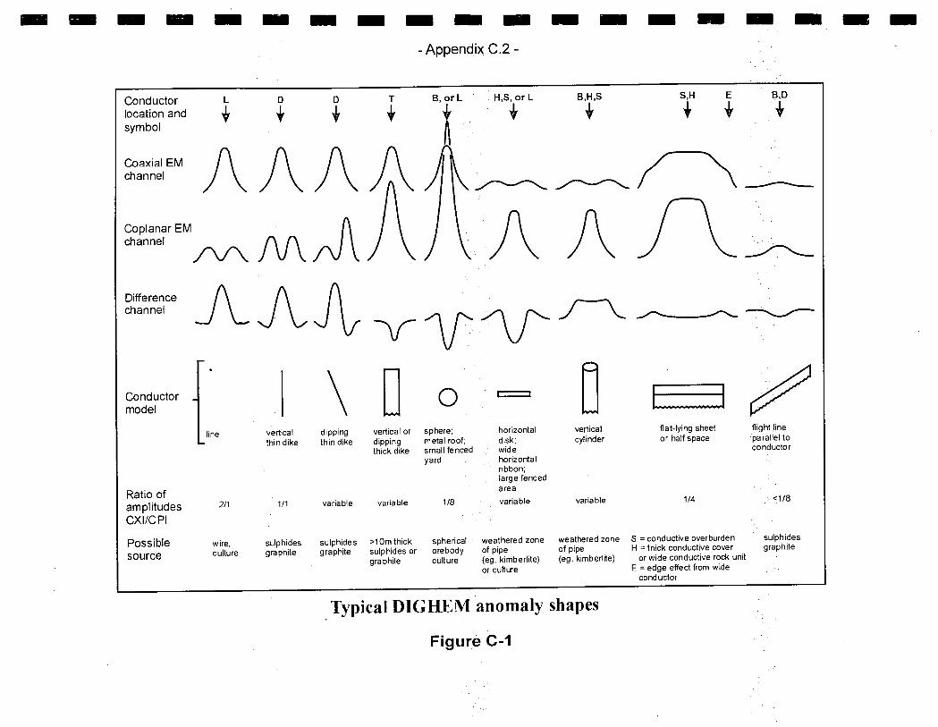
— — — — — — — — — — 1 — — — — — —
-Appendix C.2-
Conductor L 0 0 T B,orL H,S,orL B,H,S S,H E B,D
location and 3 + + + + + + + + symbol
Coaxial EM channel
Coplanar EM A I I I f channel _~ 1_~A Difference channel AAJ
Conductor model
line
\Uo I I
vertical dipping vertical or sphere; horizontal
thin dike thin dike dipping metal roof; disk; thick dike small fenced wide
yard horizontal
vertical cylinder
LJ fiat-lying sheet or half space
flight line parallel to conductor
Ratio of amplitudes CXIIC P1
Possible source
211
wire, culture
ribbon; l arge fenced area
1/1 variable variable 1/8 variable variable 1/4 <118
sulphides sulphides >l Om thick spherical weathered zone weathered zone s = conductive overburden sulphides
graphite graphite sulphides or orebody of pipe of pipe H = thick conductive cover graphite
graphite culture (eg. kimberlite) (eg. kimberlite) or wide conductive rock unit
or culture E = edge effect from wide -
conductor
Typical DIG HEM anomaly shapes
Figure c -I

- Appendix 0.3 -
The conductance value is a geological parameter because it is a characteristic of the conductor. alone. It generally is independent of frequency, flying height or depth of burial, apart from the averaging over a greater portion of the conductor as height increases Small anomalies from deeply buried strong conductors are not confused with small anomalies from shallow weak conductors because the former will have larger conductance values.
Table C-I. EM Anomaly Grades
Anomaly Grade Siemens I 7 >100 6 50 - 100 5 20 - 50 4 10 - 20 3 5-10 2 1- 5 1 < 1
Conductive overburden generally produces broad EM responses which may not be shown as anomalies on the geophysical maps. However, patchy conductive overburden in otherwise resistive areas can yield discrete anomalies with a conductance grade (cf. Table C-i) of i, 2 or even 3 for conducting clays which have resistivities as low as 50 ohm-m. In areas where ground resistivities are below iO ohm-m, anomalies caused by weathering variations and similar causes can have any conductance grade. The anomaly shapes from the multiple coils often allow such conductors to be recognized, and these are indicated by the letters 5, H, and sometimes E on the geophysical maps (see EM legend on maps).
For bedrock conductors, the higher anomaly grades indicate increasingly higher
I conductances. Examples: the New Insco copper discovery (Noranda, Canada) yielded a grade 5 anomaly, as did the neighbouring copper-zinc Magusi River ore body; Mattabi (copper-zinc, Sturgeon Lake, Canada) and Whistle (nickel, Sudbury, Canada) gave grade 6;
I and the Montcalm nickel-copper discovery (Timmins, Canada) yielded a grade 7 anomaly. Graphite and sulphides can span all grades but, in any particular survey area, field work may show that the different grades indicate different types of conductors.
Strong conductors (i.e., grades 6 and 7) are characteristic of massive sulphides or graphite. Moderate conductors (grades 4 and 5) typically reflect graphite or sulphides of a less massive character, while weak bedrock conductors (grades i to 3) can signify poorly connectedgraphite or heavily disseminated sulphides. Grades i and 2 conductors may not respond to ground EM equipment using frequencies less than 2000 Hz.
The presence of sphalerite or gangue can result in ore deposits having weak to moderate conductances. As an example, the three million ton lead-zinc deposit of Restigouche Mining Corporation near Bathurst, Canada, yielded a well-defined grade 2 conductor. The 10 percent by volume of sphalerite occurs as a coating around the fine grained massive pyrite, thereby inhibiting electrical conduction. Faults, fractures and shear zones may produce anomalies that typically have low conductances (e.g., grades 1 to 3). Conductive rock formations can yield anomalies of any conductance grade. The conductive materials in
I I I
I I I I I I I
I I I I

- Appendix C.4 -
such rock formations can be salt water, weathered products such as days, original
depositional clays, and carbonaceous material.
For each interpreted electromagnetic anomaly on the geophysical maps, a letter identifier and an interpretive symbol are plotted beside the EM grade symbol. The horizontal rows of dots, under the interpretive symbol, indicate the anomaly amplitude on the flight record. The vertical column of dots, under the anomaly letter, gives the estimated depth. In areas where anomalies are crowded, the letter identifiers, interpretive symbols and dots may be obliterated. The EM grade symbols, however, will always be discernible, and the obliterated information can be obtained from the anomaly listing appended to this report.
The purpose of indicating the anomaly amplitude by dots is to provide an estimate of the reliability of the conductance calculation. Thus, a conductance value obtained from a large ppm anomaly (3 or 4 dots) will tend to be accurate whereas one obtained from a small ppm anomaly (no dots) could be quite inaccurate. The absence of amplitude dots indicates that the anomaly from the coaxial coil-pair is 5 ppm or less on both the in-phase and quadrature channels. Such small anomalies could reflect a weak conductor at the surface or a stronger conductor at depth. The conductance grade and depth estimate illustrates which of these
possibilities fits the recorded data best.
The conductance measurement is considered more reliable than the depth estimate. There are a number of factors that can produce an error in the depth estimate including the averaging of topographic variations by the altimeter, overlying conductive overburden, and the location and attitude of the conductor relative to the flight line. Conductor location and attitude can provide an erroneous depth estimate because the stronger part of the conductor may be deeper or to one side of the flight line, or because it has a shallow dip. A heavy tree cover can also produce errors in depth estimates. This is because the depth estimate is computed as the distance of bird from conductor, minus the altimeter reading. The altimeter can lock onto the top of a dense forest canopy. This situation yields an erroneously large depth estimate but does not affect the conductance estimate.
I Dip symbols are use used only when the resistive environment.
I to indicate the direction of dip of conductors. These symbols are anomaly shapes are unambiguous, which usually requires a fairly
A further interpretation is presented on the EM map by means of the line-to-line correlation of bedrock anomalies, which is based on a comparison of anomaly shapes on adjacent lines. This provides conductor axes that may define the geological structure over portions of the survey area. The absence of conductor axes in an area implies that anomalies could not be correlated from line to line with reasonable confidence.
The electromagnetic anomalies are designed to provide a correct impression of conductor quality by means of the conductance grade symbols. The symbols can stand alone with geology when planning a follow-up program. The actual conductance values are printed in the attached anomaly list for those who wish quantitative data. The anomaly ppm and depth are indicated by inconspicuous dots which should not distract from the conductor patterns, while being helpful to those who wish this information. The map provides ar
I I I I I I I I I I I I
I I I I I

- Appendix C.5 -
interpretation of conductors in terms of length, strike and dip, geometric shape, conductance, depth, and thickness. The accuracy is comparable to an interpretation from a high quality ground EM survey having the same line spacing
The appended EM anomaly list provides a tabulation of anomalies in ppm, conductance,
I and depth for the vertical sheet model. No conductance or depth estimates are shown for weak anomalous responses that are not of sufficient amplitude to yield reliable calculations.
Since discrete bodies normally are the targets of EM surveys, local base (or zero) levels are used to compute local anomaly amplitudes. This contrasts with the use of true zero levels which are used to compute true EM amplitudes. Local anomaly amplitudes are shown in the EM anomaly list and these are used to compute the vertical sheet parameters of conductance and depth.
Questionable Anomalies
The EM maps may contain anomalous responses that are displayed as asterisks (*) These responses denote weak anomalies of indeterminate conductance, which may reflect one of the following: a weak conductor near the surface, a strong conductor at depth (e.g., 100 to 120 m below surface) or to one side of the flight line, or aerodynamic noise. Those responses that have the appearance of valid bedrock anomalies on the flight profiles are indicated by appropriate interpretive symbols (see EM legend on maps). The others probably do not warrant further investigation unless their locations are of considerable geological interest.
The Thickness Parameter
A comparison of coaxial and coplanar shapes can provide an indication of the thickness of a steeply dipping conductor. The amplitude of the coplanar anomaly (e.g., CPI channel) increases relative to the coaxial anomaly (e.g., CXI) as the apparent thickness increases, i.e., the thickness in the horizontal plane. (The thickness is equal to the conductor width if the conductor dips at 90 degrees and strikes at right angles to the flight line.) This report refers to a conductor as thin when the thickness is likely to be less than 3 m, and thick when in excess of 10 m. Thick conductors are indicated on the EM map by parentheses '( )'. For base metal exploration in steeply dipping geology, thick conductors can be high priority targets because many massive sulphide ore bodies are thick. The system cannot sense the thickness when the strike of the conductor is subparallei to the flight line, when the conductor has a shallow dip, when the anomaly amplitudes are small, or when the resistivity of the environment is below 100 ohm-m.
Resistivity Mapping
Resistivity mapping is useful in areas where broad or flat lying conductive units are of interest. One example of this is the clay alteration which is associated with Carlin-type
I I I I
I I I I I I I I I I I I I I

- Appendix C.6 -
deposits in the south west United States. The resistivity parameter was able to identify the clay alteration zone over the Cove deposit. The alteration zone appeared as a strong resistivity low on the 900 Hz resistivity parameter. The 7,200 Hz and 66,000 Hz resistivities showed more detail in the covering sediments, and delineated a range front fault. This is typical in many areas of the south west United States, where conductive near surface sediments, which may sometimes be alkalic, attenuate the higher frequencies.
Resistivity mapping has proven successful for locating diatremes in diamond exploration. Weathering products from relatively soft kimberlite pipes produce a resistivity contrast with the unaltered host rock. In many cases weathered kimberlite pipes were associated with thick conductive layers that contrasted with overlying or adjacent relatively thin layers of lake bottom sediments or overburden.
Areas of widespread conductivity are commonly encountered during surveys. These conductive zones may reflect alteration zones, shallow-dipping sulphide or graphite-rich units, saline ground water, or conductive overburden. In such areas, EM amplitude changes can be generated by decreases of only 5 m in survey altitude, as well as by increases in conductivity. The typical flight record in conductive areas is characterized by in-phase and quadrature channels that are continuously active. Local EM peaks reflect either increases in conductivity of the earth or decreases in survey altitude. For such conductive areas, apparent resistivity profiles and contour maps are necessary for the correct interpretation of the airborne data.,The advantage of the resistivity parameter is that anomalies caused by altitude changes are virtually eliminated, so the resistivity data reflect only those anomalies caused by conductivity changes. The resistivity analysis also helps the interpreter to differentiate between conductive bedrock and conductive overburden. For example, discrete conductors will generally appear as narrow lows on the contour map and broad conductors (e.g., overburden) will appear as wide lows.
The apparent resistivity is calculated using the pseudo-layer (or buried) half-space model
defined by Fraser (1978) 6 . This model consists of a resistive layer overlying a conductive half-space. The depth channels give the apparent depth below surface of the conductive material. The apparent depth is simply the apparent thickness of the overlying resistive layer. The apparent depth (or thickness) parameter will be positive when the upper layer is more resistive than the underlying material, in which case the apparent depth may be quite close to the true depth.
The apparent depth will be negative when the upper layer is more conductive than the underlying material, and will be zero when a homogeneous half-space exists. The apparent depth parameter must be interpreted cautiously because it will contain any errors that might exist in the measured altitude of the EM bird (e.g., as caused by a dense tree cover). The inputs to the resistivity algorithm are the in-phase and quadrature components of the coplanar coil-pair. The outputs are the apparent resistivity of the conductive half-space (the
6 Resistivity mapping with an airborne multicoil electromagnetic system: Geophysics, v. 43, p. 144-172
I I I I I I I I I I I I I I I I I I I

I I
- Appendix 0.7 -
source) and the sensor-source distance. The flying height is not an input variable, and the output resistivity and sensor-source distance are independent of the flying height when the conductivity of the measured material is sufficient to yield significant in-phase as well as quadrature responses. The apparent depth, discussed above, is simply the sensor-source distance minus the measured altitude or flying height. Consequently, errors in the measured attitude will affect the apparent depth parameter but not the apparent resistivity parameter.
I The apparent depth parameter is a useful indicator of simple layering in areas lacking a heavy tree cover. Depth information has been used for permafrost mapping, where positive apparent depths were used as a measure of permafrost thickness. However, little
I quantitative use has been made of negative apparent depths because the absolute value of the negative depth is not a measure of the thickness of the conductive upper layer and, therefore, is not meaningful physically. Qualitatively, a negative apparent depth estimate
I usually shows that the EM anomaly is caused by conductive overburden. Consequently, the apparent depth channel can be of significant help in distinguishing between overburden and bedrock conductors.
Interpretation in Conductive Environments
Environments having low background resistivitjes (e.g., below 30 ohm-m for a 900 Hz system) yield very large responses from the conductive ground. This usually prohibits the recognition of discrete bedrock conductors. However, Fugro data processing techniques produce three parameters that contribute significantly to the recognition of bedrock conductors in conductive environments. These are the in-phase and quadrature difference channels (DIFI and DIFQ, which are available only on systems with "common" frequencies on orthogonal coil pairs), and the resistivity and depth channels (RES and DEP) for each coplanar frequency.
The EM difference channels (DIFI and DIFQ) eliminate most of the responses from conductive ground, leaving responses from bedrock conductors, cultural features (e.g., telephone lines, fences, etc.) and edge effects. Edge effects often occur near the perimeter of broad conductive zones. This can be a source of geologic noise. While edge effects yield anomalies on the EM difference channels, they do not produce resistivity anomalies. Consequently, the resistivity channel aids in eliminating anomalies due to edge effects. On the other hand, resistivity anomalies will coincide with the most highly conductive sections of conductive ground, and this is another source of geologic noise. The recognition of a bedrock conductor in a conductive environment therefore is based on the anomalous responses of the two difference channels (DIFI and DIFQ) and the resistivity channels (RES). The most favourable situation is where anomalies coincide on all channels.
The DEP channels, which give the apparent depth to the conductive material, also help to determine whether a conductive response arises from surficial material or from a conductive zone in the bedrock. When these channels ride above the zero level on the depth profiles (i.e., depth is negative), it implies that the EM and resistivity profiles are responding primarily to a conductive upper layer, i.e., conductive overburden. If the DEP channels are below the zero level, it indicates that a resistive upper layer exists, and this usually implies the
I I I
I I I I N I I I I I I

I I
- Appendix C.8 -
existence of a bedrock conductor. If the low frequency DEP channel is below the zero level and the high frequency DEP is above, this suggests that a bedrock conductor occurs beneath conductive cover.
Reduction of Geologic Noise
Geologic noise refers to unwanted geophysical responses. For purposes of airborne EM surveying, geologic noise refers to EM responses caused by conductive overburden and magnetic permeability. It was mentioned previously that the EM difference channels (i.e., channel DIFI for in-phase and DIFQ for quadrature) tend to eliminate the response of conductive overburden.
Magnetite produces a form of geological noise on the in-phase channels. Rocks containing less than 1% magnetite can yield negative in-phase anomalies caused by magnetic permeability. When magnetite is widely distributed throughout a survey area, the in-phase EM channels may continuously rise and fall, reflecting variations in the magnetite percentage, flying height, and overburden thickness. This can lead to difficulties in recognizing deeply buried bedrock conductors, particularly if conductive overburden also exists. However, the response of broadly distributed magnetite generally vanishes on the in-phase difference channel DIFI. This feature can be a significant aid in the recognition of conductors that occur in rocks containing accessory magnetite.
EM Magnetite Mapping
The information content of HEM data consists of a combination of conductive eddy current responses and magnetic permeability responses. The secondary field resulting from conductive eddy current flow is frequency-dependent and consists of both in-phase and quadrature components, which are positive in sign. On the other hand, the secondary field resulting from magnetic permeability is independent of frequency and consists of only an in-phase component that is negative in sign. When magnetic permeability manifests itself by decreasing the measured amount of positive in-phase, its presence may be difficult to recognize. However, when it manifests itself by yielding a negative in-phase anomaly (e.g., in the absence of eddy current flow), its presence is assured. In this latter case, the negative component can be used to estimate the percent magnetite content.
A magnetite mapping technique, based on the low frequency coplanar data, can be complementary to magnetometer mapping in certain cases. Compared to magnetometry, it is far less sensitive but is more able to resolve closely spaced magnetite zones, as well as providing an estimate of the amount of magnetite in the rock. The method is sensitive to 1/4% magnetite by weight when the EM sensor is at a height of 30 m above a magnetitic half-space. It can individually resolve steep dipping narrow magnetite-rich bands which are separated by 60 m. Unlike magnetometry, the EM magnetite method is unaffected by remanent magnetism or magnetic latitude.
The EM magnetite mapping technique provides estimates of magnetite content which are usually correct within a factor of 2 when the magnetite is fairly uniformly distributed. EM
I 1.
1..
I I I I I
I I I I I 1 I I I

1 I I
- Appendix 0.9 -
magnetite maps can be generated when magnetic permeability is evident as negative in-phase responses on the data profiles. -
Like magnetometry, the EM magnetite method maps only bedrock features, provided that the overburden is characterized by a general lack of magnetite. This contrasts with resistivity mapping which portrays the combined effect of bedrock and overburden.
The Susceptibility Effect
When the host rock is conductive, the positive conductivity response will usually dominate the secondary field, and the susceptibility effect will appear as a reduction in the in-phase, rather than as a negative value. The in-phase response will be lower than would be predicted by a model using zero susceptibility. At higher frequencies the in-phase conductivity response also gets larger, so a negative magnetite effect observed on the low frequency might not be observable on the higher frequencies, over the same body. The susceptibility effect is most obvious over discrete magnetite-rich zones, but also occurs over uniform geology such as a homogeneous half-space.
High magnetic susceptibility will affect the calculated apparent resistivity, if only conductivity is considered. Standard apparent resistivity algorithms use a homogeneous half-space model, with zero susceptibility. For these algorithms, the reduced in-phase response will, in most cases, make the apparent resistivity higher than it should be. It is important to note that there is nothing wrong with the data, nor is there anything wrong with the processing algorithms. The apparent difference results from the fact that the simple geological model used in processing does not match the complex geology.
Measuring and Correcting the Magnetite Effect
Theoretically, it is possible to calculate (forward model) the combined effect of electrical conductivity and magnetic susceptibility on an EM response in all environments. The difficulty lies, however, in separating out the susceptibility effect from other geological effects when deriving resistivity and susceptibility from EM data.
Over a homogeneous half-space, there is a precise relationship between in-phase, quadrature, and altitude. These are often resolved as phase angle, amplitude, and altitude. Within a reasonable range, any two of these three parameters can be used to calculate the half space resistivity. If the rock has a positive magnetic susceptibility, the in-phase component will be reduced and this departure can be recognized by comparison to the other parameters.
Magnetic susceptibility and permeability are two measures of the same physical property. Permeability is generally given as relative permeability, p, which is the permeability of the
substance divided by the permeability of free space (4 7T x 10- ). Magnetic susceptibility k is
related to permeability by k--p'-1. Susceptibility is a unitless measurement, and is usually reported in units of I 06. The typical range of susceptibilities is —1 for quartz, 130 for pyrite, and
up to 5 x 10⁵ for magnetite, in 10 -6 units (Telford et at, 1986).
I I I I I I I I I I I I I U I

-Appendix C. 10 -
I The algorithm used to calculate apparent susceptibility and apparent resistivity from
I HEM data uses a homogeneous half-space geological model Non half-space geology, such as horizontal layers or dipping sources, can also distort the perfect half-space relationship of the three data parameters. While it may be possible to use more complex
I models to calculate both rock parameters, this procedure becomes very complex and time-consuming. For basic HEM data processing, it is most practical to stick to the simplest geological model.
Magnetite reversals (reversed in-phase anomalies) have been used for many years to calculate an "FeO"or magnetite response from HEM data (Fraser, 1981). However, this technique could only be applied to data where the in-phase was observed to be negative, which happens when susceptibility is high and conductivity is low.
Applying Susceptibility Corrections
Resistivity calculations done with susceptibility correction may change the apparent resistivity. High-susceptibility conductors, that were previously masked by the susceptibility effect in standard resistivity algorithms, may become evident. In this case the susceptibility corrected apparent resistivity is a better measure of the actual resistivity of the earth. However, other geological variations, such as a deep resistive layer, can also reduce the in-phase by the same amount In this case susceptibility correction would not be the best method. Different geological models can apply in different areas of the same data set. The effects of susceptibility, and other effects that can create a similar response, must be considered when selecting the resistivity algorithm.
Susceptibility from EM vs Magnetic Field Data
The response of the EM system to magnetite may not match that from a magnetometer survey. First, HEM-derived susceptibility is a rock property measurement, like resistivity. Magnetic data show the total magnetic field, a measure of the potential field, not the rock property. Secondly, the shape of an anomaly depends on the shape and direction of the source magnetic field. The electromagnetic field of HEM is much different in shape from the earth's magnetic field. Total field magnetic anomalies are different at different magnetic latitudes; HEM susceptibility anomalies have the same shape regardless of their location on the earth.
In far northern latitudes, where the magnetic field is nearly vertical, the total magnetic field measurement over a thin vertical dike is very similar in shape to the anomaly from the HEM-derived susceptibility (a sharp peak over the body). The same vertical dike at the magnetic equator would yield a negative magnetic anomaly, but the HEM susceptibility anomaly would show a positive susceptibility peak.
I I
I I I I I I I I I I I I I I

-Appendix C.11 -
Effects of Permeability and Dielectric Permittivity
Resistivity algorithms that assume free-space magnetic permeability and dielectric permittivity, do not yield reliable values in highly magnetic or highly resistive areas. Both magnetic polarization and displacement currents cause a decrease in the in-phase component, often resulting in negative values that yield erroneously high apparent resistivities. The effects of magnetite occur at all frequencies, but are most evident at the lowest frequency. Conversely, the negative effects of dielectric permittivity are most evident at the higher frequencies, in resistive areas.
The table below shows the effects of varying permittivity over a resistive (10,000 ohm-m) half space, at frequencies of 56,000 Hz (DIGHEMV) and 102,000 Hz (RESOLVE).
Apparent Resistivity Calculations Effects of Permittivity on in-phase/Quadrature/Resistivity
Freq Coil Sep Thres Alt "In Quad App App Depth Permithvity (Hz) (m) (ppm) (m) Phase Phase Res - (m)
56,000 CP 6.3 0.1 30 7.3 35.3 10118 -1.0 1 Air
56,000 CP 6.3 0.1 30 3.6 36.6 19838 -13.2 5 Quartz
56,000 CP 6.3 0.1 30 -1.1 38.3 81832 -25.7 10 Epidote
56,000 CP 6.3 0.1 30 -10.4 42.3 76620 -25.8 20 Granite
56,000 CID 6.3 0.1 30 -19.7 46.9 71550 -26.0 30 Diabase
56,000 CP 6.3 0.1 30 -28.7 52.0 66787 -26.1 40 Gabbro
102,000 CP 7.86 0.1 30 32.5 117.2 9409 -0.3 lAir
102,000 CID 7.86 0.1 30 11.7 127.2 25956 -16.8 _S Quartz
102,000 CP 7.86 0.1 30 -14.0 141.6 97064 -26.5 10 Epidote
102,000 CID 7.86 0.1 30 -62.9 176.0 83995 -26.8 20 Granite
102,000 CP 7.86 0.1 30 -107.5 215.8 73320 -27.0 30 Diabase
102,0001 CP 7.86 0.1 30 -147.1 259.2 64875 -27.2 40 Gabbro
Methods have been developed (Huang and Fraser, 2000, 2001) to correct apparent resistivities for the effects of permittivity and permeability. The corrected resistivities yield more credible values than if the effects of permittivity and permeability are disregarded.
Recpgnition of Culture
Cultural responses include all EM anomalies caused by man-made metallic objects. Such anomalies may be caused by inductive coupling or current gathering. The concern of the interpreter is to recognize when an EM response is due to culture. Points of consideration used by the interpreter, when coaxial and coplanar coil-pairs are operated at a common frequency, are as follows:
I I I I I I I I I I I I I I I I I I I

-Appendix C.12 -
Channels CXPL and CPPL monitor 60 Hz radiation. An anomaly on these channels shows that the conductor is radiating power. Such an indication is normally a guarantee that the conductor is cultural However, care must be taken to ensure that the conductor is not a geologic body that strikes across a power line, carrying leakage currents.
2. A flight that crosses a 'line (e.g., fence, telephone line, etc.) yields a centre-peaked coaxial anomaly and an m-shaped coplanar anomaly. 8 When the flight crosses the cultural line at a high angle of intersection, the amplitude ratio of coaxial/coplanar response is 2. Such an EM anomaly can only be caused by a line. The geologic body that yields anomalies most closely resembling a line is the vertically dipping thin dike. Such a body, however, yields an amplitude ratio of 1 rather than 2. Consequently, an m-shaped coplanar anomaly with a CXI/CPI amplitude ratio of 2 is virtually a guarantee that the source is a cultural line.
I 3. A flight that crosses a sphere or horizontal disk yields centre-peaked coaxial and coplanar anomalies with a CXI/CPI amplitude ratio (i.e., coaxial/coplanar) of 1/8. In the absence of geologic bodies of this geometry, the most likely conductor is a metal
I
roof or small fenced yard. 9 Anomalies of this type are virtually certain to be cultural if they occur in an area of culture.
I I I
I I I
A flight that crosses a horizontal rectangular body or wide ribbon yields an m shaped coaxial anomaly and a centre-peaked coplanar anomaly. In the absence of geologic bodies of this geometry, the most likely conductor is a large fenced area. 5 Anomalies of this type are virtually certain to be cultural if they occur in an area of culture. EM anomalies that coincide with culture, as seen on the camera film or video display, are usually caused by culture. However, care is taken with such coincidences because a geologic conductor could occur beneath a fence, for example. In this example, the fence would be expected to yield an m-shaped coplanar anomaly as in case #2 above. If, instead, a centre-peaked coplanar anomaly occurred, there would be concern that a thick geologic conductor coincided with the cultural line.
I. 4
I 5
I I I I
6. The above description of anomaly she conductively coupled to the environment. inductive coupling to the EM transmitter. conductive (e.g., less than 100 ohm-m at conductively coupled to the environment. tend to be governed by current gathering.
pes is valid when the culture is not In this case, the anomalies arise from
However, when the environment is quite 900 Hz), the cultural conductor may be In this latter case, the anomaly shapes Current gathering can completely distort
I See Figure C-i presented earlier. It is a characteristic of EM that geometrically similar anomalies are obtained from: (1) a
I planar conductor, and (2) a wire which forms a loop having dimensions identical to the perimeter of the equivalent planar conductor.
I I

I I
-Appendix C.13 -
the anomaly shapes, thereby complicating the identification of cultural anomalies. In - such circumstances, the interpreter can only rely on the radiation channels and on
the camera film or video records
Magnetic Responses
The measured total magnetic field provides information on the magnetic properties of the earth materials in the survey area. The information can be used to locate magnetic bodies of direct interest for exploration, and for structural and lithological mapping.
The total magnetic field response reflects the abundance of magnetic material in the source. Magnetiteis the most common magnetic mineral. Other minerals such as ilmenite, pyrrhotite, franklinite, chromite, hematite, arsenopyrite, limonite and pyrite are also magnetic, but to a lesser extent than magnetite on average.
In some geological environments, an EM anomaly with magnetic correlation has a greater likelihood of being produced by sulphides than one which is non-magnetic. However, sulphide ore bodies may be non-magnetic (e.g., the Kidd Creek deposit near Timmins, Canada) as well as magnetic (e.g., the Mattabi deposit near Sturgeon Lake, Canada).
Iron ore deposits will be anomalously magnetic in comparison to surrounding rock due to the concentration of iron minerals such as magnetite, ilmenite and hematite.
Changes in magnetic susceptibility often allow rock units to be differentiated based on the total field magnetic response. Geophysical classifications may differ from geological classifications if various magnetite levels exist within one general geological classification. Geometric considerations of the source such as shape, dip and depth, inclination of the earth's field and remanent magnetization will complicate such an analysis.
In general, mafic lithologies contain more magnetite and are therefore more magnetic than many sediments which tend to be weakly magnetic. Metamorphism and alteration can also increase or decrease the magnetization of a rock unit.
Textural differences on a total field magnetic contour, colour or shadow map due to the frequency of activity of the magnetic parameter resulting from inhomogeneities in the distribution of magnetite within the rock, may define certain lithologies. For example, near surface volcanics may display highly complex contour patterns with little line-to-line correlation.
I 1 I I
I I U I I I I I
Rock units may be differentiated based on t responses. Mafic intrusive plugs can appear intrusives appear as sub-circular zones, and metamorphism. Generally, granitic terrain will granite gneiss may display strike.
e plan shapes of their total field magnetic as isolated 'bulls-eye" anomalies. Granitic may have contrasting rings due to contact lack a pronounced strike direction, although
I I I I

U U I U U I I I
I I I I I I I I U I
-Appendix C.14 -
Linear north-south units are theoretically not well-defined on total field magnetic maps in equatorial regions due to the low inclination of the earth's magnetic field. However, most stratigraphic units will have variations in composition along strike that will cause the units to appear as a series of alternating magnetic highs and lows.
Faults and shear zones may be characterized by alteration that causes destruction of magnetite (e.g., weathering) that produces a contrast with surrounding rock. Structural breaks may be filled by magnetite-rich, fracture filling material as is the case with diabase dikes, or by non-magnetic felsic material.
Faulting can also be identified by patterns in the magnetic total field contours or colours. Faults and dikes tend to appear as lineaments and often have strike lengths of several kilometres. Offsets in narrow, magnetic, stratigraphic trends also delineate structure. Sharp contrasts in magnetic lithologies may arise due to large displacements along strike-slip or dip-slip faults.
I

APPENDIX D
DATA ARCHIVE DESCRIPTION
I I I I I I I I I I I. I I I I I I I I

This CD-ROM contains final data archives of an airborne survey conducted by Fugro Airborne Surveys on behalf of 977554 Alberta Ltd. The survey was flown on December 31, 2003.
Fugro Job #03094
CD Archive number: CCDO1990
I I I I I I I I I
1. LineData:
XYZ data in Geosoft format, along with format description. SEGY files
2. Grids: Grids in Photon format for the following parameters: 1. Magnetic Total Field 2. Differential Resistivity 400 Hz Coplanar 3. Differential Resistivity 1500 Hz Coplanar 4. Differential Resistivity 6200 Hz Coplanar 5. Differential Resistivity 25 kHz Coplanar 6. Differential Resistivity 100 kHz Coplanar
4. Report in MS-Word 2000.
Proiection Description
Datum: NAD27 (Alberta and BC) EHipsoid: Clarke 1866 Projection: UTM (Zone:1 1 N) Central Meridian: 1171) W False Northing: 0 False Easting: 500000 Scale Factor: 0.9996 WG584 to Local Conversion: Molodensky Datum Shifts (DX, DY, DZ): 7, -162, -188
I I I I I I I I I I
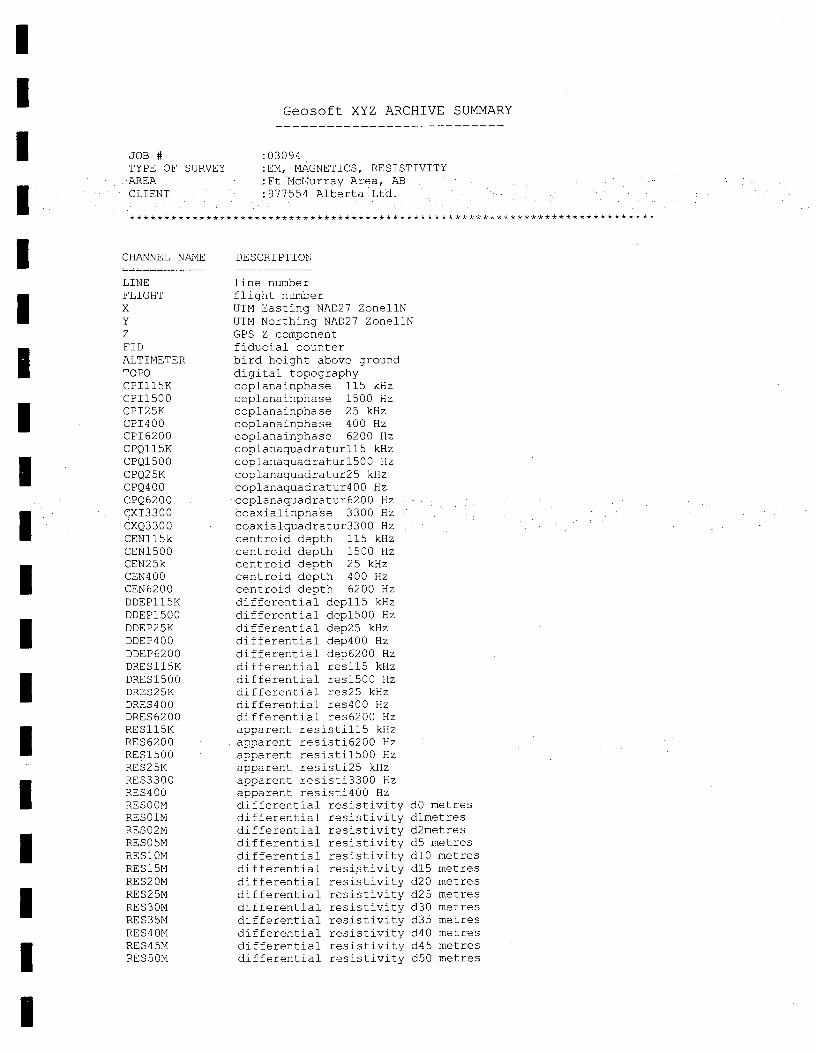
I I Geosoft XYZ ARCHIVE SUMMARY
I JOB # :03094 TYPE OF SURVEY :EM, MAGNETICS, RESISTIVITY AREA :Ft McMurray Area, AB CLIENT 977554 Alberta Ltd
************************** *************************************************
CHANNEL NAME
LINE FLIGHT x Y Z FID ALTIMETER TOPO CPI115K CPI1500 CPI25K CPI400 CP16200 CPQ115K CPQ1500 CPQ25K CPQ400 CPQ6200 CXI 3300 CXQ3300 CEN115k CEN1500 CEN25k CEN400 CEN 6200 DDEP115K DDEP1500 DDEP25K DDEP400 DDEP 62 00 DRES115K DRES 1500 DRES25K DRES400 DRES 62 00 RE S 115K RE 5 62 0 0 RES1500 RES2 5K RE S3300 RE S400 RESOOM RESO1N RES 0 2N RESO5M RE S 10M RE S 15M RE S2 ON RES25M RES3OM RES35M RE 5 4 ON RES45M RES 5 OM
DESCRIPTION
line number flight number UTM Easting NAD27 ZonellN UTM Northing NAD27 ZoneliN GPS Z component fiducial counter bird height above ground digital topography coplanainphase 115 kHz coplanainphase 1500 Hz coplanainphase 25 kHz coplanainphase 400 Hz coplanainphase 6200 Hz coplanaquadraturlls kHz coplanaquadraturlsOO Hz coplanaquadratur25 kHz coplanaquadratur400 Hz coplanaquadratur6200 Hz coaxialinphase 3300 Hz coaialquadratur3300 Hz centroid depth 115 kHz centroid depth 1500 Hz centroid depth 25 kHz centroid depth 400 Hz centroid depth 6200 Hz differential depllS kHz differential dep1500 Hz differential dep25 kHz differential dep400 Hz differential dep6200 Hz differential resllS kHz differential reslSOO Hz differential re325 kHz differential res400 Hz differential res6200 Hz apparent resistill5 kHz apparent resisti6200 Hz apparent resistil500 Hz apparent resisti25 kHz apparent resisti3300 Hz apparent resisti400 Hz differential resistivity dO metres differential resistivity dlmetres differential resistivity d2metres differential resistivity d5 metres differential resistivity dlO metres differential resistivity d15 metres differential resistivity d20 metres differential resistivity d25 metres differential resistivity d30 metres differential resistivity d35 metres differential resistivity d40 metres differential resistivity d45 metres differential resistivity d50 metres
I I I I I
I I I I I I I I I

I RES55M differential resistivity d55 metres RES60M differential resistivity d60 metres
I RES65M differential resistivity d65 metres RES70M differential resistivity d70 metres RES75M differential resistivity d75 metres RES80M differential resistivity d80 metres
I RES85M differential resistivity d85 metres RES90M differential resistivity d90 metres MAG total magnetic field
I ISSUE DATE :January 19, 2003 FOR WHOM :977554 Alberta Ltd.
BY WHOM :FUGRO AIRBORNE SURVEYS CORP. 2270 ARGENTIA ROAD
I MISSISSAUGA, ONTARIO, CANADA L5N 6A6 TEL. (905) 812-0212 FAX (905) 812-1504
I
I I I I I I I
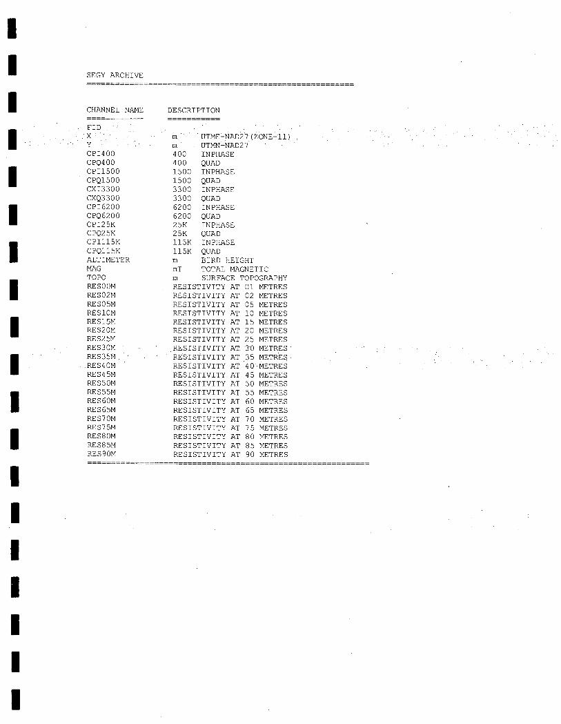
I SEGY ARCHIVE
CHANNEL NAME DESCRIPTION
FID.
xm
UTME-NAD27 (ZONE-11) Y m UTMN-N 7\D27 CP1400 400 INPHASE CPQ400 400 QUAD
CPI1500
1500 INPHASE CPQ1500 1500 QUAD CX13300 3300 INPHASE CXQ3300 3300 QUAD
CP16200
6200 INPHASE CPQ6200 6200 QUAD CPI25K 25K INPHASE CPQ25K 25K QUAD
CPI115K
115K INPHASE CPQ115K 115K QUAD ALTIMETER rn BIRD HEIGHT MAG nT TOTAL MAGNETIC
TOPO
SURFACE TOPOGRAPHY RESOOM RESISTIVITY AT 01 METRES RES02M RESISTIVITY AT 02 METRES RES05M RESISTIVITY AT 05 METRES RES10M RESISTIVITY AT 10 METRES
RES15M
RESISTIVITY AT 15 METRES RES20M RESISTIVITY AT 20 METRES RES25M RESISTIVITY AT 25 METRES RES30M RESISTIVITY AT 30 METRES
RES35M
RESISTIVITY AT 35 METRES RES40M RESISTIVITY AT 40 METRES RES45M RESISTIVITY AT 45 METRES RESSOM RESISTIVITY AT 50 METRES
RES55M
RESISTIVITY AT 55 METRES RES60M RESISTIVITY AT 60 METRES RES65M RESISTIVITY AT 65 METRES RES70M RESISTIVITY AT 70 METRES
RES75M
RESISTIVITY AT 75 METRES RES80M RESISTIVITY AT 80 METRES RES85M RESISTIVITY AT 85 METRES RES90M RESISTIVITY AT 90 METRES
I I I I I I I
-a m 2:
.0 >(
I I I
977554 Alberta Ltd.
I ASSESSMENT REPORT
I
LEGEND PROSPECT
I I I I I I I I I I I I I I
APPENDIX 4 Diamond Drilling
Bob Ryziuk Geolink Exploration Ltd. 10961 University Avenue Edmonton, Alberta T6G 1Y1
977554 Alberta Ltd. 4700 - 888 3rd Street SW
Calgary, Alberta T2P 505

I I I I I
REPORT ON DIAMOND DRILLING February - March 2004 LEGEND PROSPECT
Northern Alberta
Four holes were drilled between February 201h and March 5th, 2004 The holes were located to test airborne EM anomalies consistent with kimberlite signatures. The drill hole locations are listed below.
I I I
Hole Number
DDHO4-1
DDHO4-2
DDHO4-3
0 DH04-4
DIAMOND DRILL HOLE LOCATIONS
LEGEND PROSPECT
UTM Zone 12 NA027
Easting Northing NTS Map
426611 6306095 84A116
415761 6308836 84A116
427151 6306044 84A116
425561 6332776 84 H/1
Total Depth (metres)
73.2
93.3
91.4
30.5
All holes were accessed by existing cut line cleared of snow. Hole DDH04-1 was located on a cut line. Holes DDH04-2 and DDH04-3 required small (15 by 15 metre) clearings in swamp spruce Hole DDH04-4 required 70 metres of new road to be built through 2" to 12" poplar trees.
I None of the holes encountered kimberlite and no core was recovered. Each hole was drilled with a tn-cone bit and drill cuttings were observed but not sampled. All holes bottomed in what appeared to be unconsolidated glacial till.
I Aggressive Diamond Drilling Ltd. of Kelowna, B.C. was contracted to drill the targets. A unitized skid-mounted Boyles 25-A drill was used to drill NQ-2 core.
I
All holes were vertical.
A water truck was hired from Fort McMurray and a D4 Cat was used to build drill
I
pads and move the drill.
Figures 1 to 4 summarize each hole.
I I I I
I I
I

Hole lost at
I I I I I I I I I I I I I I I I I I I
UTM NAD 27 Zone 12V
DDHO4-1
Vertical 426611 East
6306095 North
No core recovered Unconsolidated till with large boulders
73.2 metres
977554 ALBERTA LTD.
LEGEND PROSPECT Target 4
Diamond Drill Hole - DDH04-1 Geolink Exploration Ltd I April 2004 1 NTS: 84A/16 I
Fiaure 1
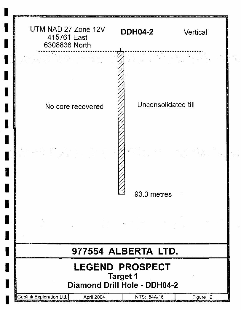
I
I I I
I I I I I
I I I I I I I I

I
I I I I I I I I I I I I I I I I I I
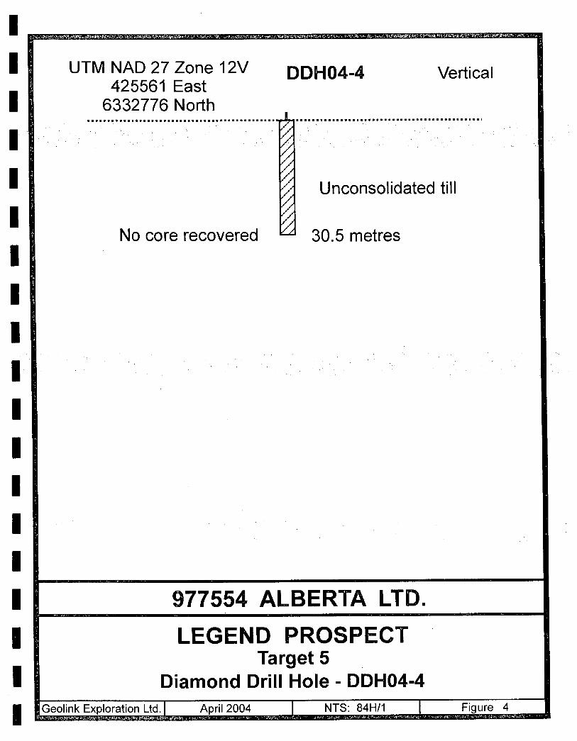
I
I I I I I I I I I I I I I I I I I I

>.
iL

1 I 1 I 'I I I I I 1 I I
1 I I I I I
Bob Ryziuk Geoiñk Exploration Ltd. 10961 University Avenue Edmonton, Alberta T6G 1Y1
977554 Alberta Ltd.
ASSESSMENT REPORT
LIEGE PROSPECT
APPENDIX 5 Statement of Expenditures
977554 Alberta Ltd 4700 - 888 3rd Street SW
Calgary, Alberta T2P 5C5
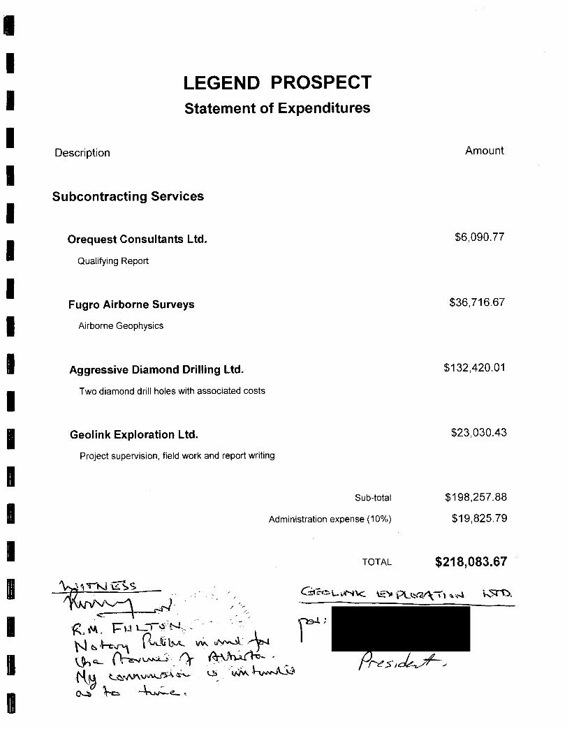
I I I I I I I I I I I N N a I N II II II
LEGEND PROSPECT Statement of Expenditures
Description
Subcontracting Services
Orequest Consultants Ltd.
Qualifying Report
Fugro Airborne Surveys
Airborne Geophysics
Aggressive Diamond Drilling Ltd.
Two diamond drill holes with associated costs
Geolink Exploration Ltd.
Project supervision, field work and report writing
Sub-total
Administration expense (10%)
TOTAL
'-r2.r\ L131&
u •
Amount
$6090.77
$36,716.67
$1 32,420.01
$23,030.43
$198,257.88
$19,825.79
$218,083.67

- - - - mmm am
LEGEND PROSPECT COST ALLOCATION
Permit 1 Assigned MAIM Permit Assessment Work Assessment Amount Exploration
Number Assessment Amount Permit Area (ha) Commencement Requirement ($/ha) Due Expenditures ($)
Date
9302050130 9,216 May 24, 2002 $5.00 $46,080.00 $0.00
9302050131 9,216 May 24, 2002 $5.00 $46,080.00 $0.00
9302050132 9,216 May 24, 2002 $5.00 $46,080.00 $0.00
9302050135 9,216 May 24, 2002 $5.00 $46,080.00 $23,040.00
9302050136 9,216 May 24, 2002 $5.00 $46,080.00 $23,040.00
9302050137 9,216 May 24, 2002 $5.00 $46,080.00 $7,680.00
9302050138 9,216 May 24, 2002 $5.00 $46,080.00 $25,600.00
9302050139 9,216 May 24, 2002 $5.00 $46,080.00 $34,560.00
9302050140 9,216 May 24,2002 $5.00 $46,080.00 $11,520.00
9302050141 9,216 May 24, 2002 $5.00 $46,080.00 $46,080.00
9302050142 9,216 May 24, 2002 $5.00 $46,080.00 $23,040.00
9302050143 9,216 May 24, 2002 $5.00 $46,080.00 $23,040.00
9302050144 9,216 May 24, 2002 $5.00 $46,080.00 $0.00
Total $218,083.67 $217,600.00

— — — — — M — — M — — — — —
LEGEND PROSPECT Assessment Applied To:
Permit Number Meridian Sections Number of Sections
9302050130 90t14 W4 None 0
9302050131 90 15 W4 None 0
9302050132 90 16 W4 None 0
9302050135 91 14 W4 12,3,10,1112,13,14,15,22,23,24,25,26,27,34,35,36 18
9302050136 91 14 W4 4,5,6,7,8,9,16,17,18,19,20,21,28,29,30,31,32,33 18
9302050137 91 15 W4 13,14,15,16,17,18 6
91 15 W4 19,20,21,22,23,24,25,26,27,28,29,30,31,32,33,34,35,36 18 93020501 38 ---
91 16 W4 35,36 2
9302050139 92 15 W4 1,2,3 4,5,6,7,8,9,10,11,12 12
92 16 W4 1,2,3,4,5,6,7,8,9,10,11,12,16,17,18 15
9302050140 92 16 W4 19,20,21,28,29,30,31,32,33 9
9302050141 92 17 W4 ito 36 36
93 14 W4 25,26,27,34,35,36 6 9302050142
94 14 W4 1,2,3,10,11,12,13,14,15,22,23,24 12
9302050143 93 14 W4 28,29,30,31,32,33 6 1
94 14 W4 4,5,6,7,8,9,16,17,18,19,20,21 12
9302050144 93 17 W4 None 0
Total 170
4 Townships, 26 Sections


R18w4 R17 R16 R15 R14 R13 R12w4 1 20 21 23 4 20 21 22 23 24 21 22 23 24 19 20 21 V 23 24 19 20 21 fl 23 24 ie o 21 22 I j 24 1$ Jo 21 22 23 24
is 14 13 18 : T95
8 9 10 11 12 7 fl 9 10 I Ii 1 12 7 8 0 10 11 12 7 j a B 10 11 12 7 1 8 9 10 11 12 10 11 1 iz 7 e 9 10 ii 12
6 5 4 3 2 1 3 4 3 2 I a 2 1 6 4 3 2 1 6 { 4 a a i I S 4 3 I 2 1
31 33 1 34 35 36 21L 32 3334 36 31 32 L
2Q2 2 272 25 30 2 2Z 27 26 26 30 2 28 27 2$ 25 ao 29 282128 2 27 : 27T2
25
-- 4-- _ -. 19 I 20 21 22 22 24 10 20 21 22 23 24 19 20 21 22 23 24 19 I o ai aa 23 24 :Iis 20 21 22 23 24
'78t - t:- :t . t817 t; T94
.. j- 7 8 S 10 11 12 7 8 9 10 11 12 7 8 9 10 11 12 7 5 9 10 11 12
: 7 6 5 10 11 12
! a 5 4 2 2 1 0 5 4 a 2 1 6 5 4 3 2 I 4 3 2 1 0 e s 4 a 2 I
I4) ai aa 33 34 35 36 3 j 32 33 34 3 3 31 32 33 34 35 36 31 32 33 34 35 35 0 31 32 33 34 35 36
—i------ H --- —±--i----4--- cm 302928 27 26l 35 I29I28I27 26 26 36 25 28 27 28 25 30 29 28 27 26 25 0 • 29 2 27 26 25 I—----- —r--- II C)
21 Z4 193O2O5O144A 1520
is :H:t-:H:
¶417115 15 :
T93
--- ----*--- S S j4 3 2 1 5 5 4 3 2 1 6 5 4 3 2 1 6 5 4 3 2 1 5 6 2 211
I 34 35 6 31 1 32 33 I 31 32 34 Z L31 32 33 34 36 38
27 93020501 40 27 26 26 30 29 28 27 26 2 j30 2 s 27 25 25 -- – - —t -- ---r--H–-- .
-:-i-;;--[-;:-• 19 [ 20 [ 25T 24 19 20 21 24 jIS I ° 21 22 23 24
9302050141 I I I . ' Is 14 13 16 1? 16 16 IA 11 18 17 16 16 4 1 15 17 15 15 14 13
L() - . —1--wr---- — — — - —r-- - 9302050139 7 I
10C')1 I 7 8 9 10 11 12
—4-_• 610r-;-3oi1 4 32 I
L() L() I 0 I 31323834 c'1 c1 i
[a_29 28 279302050138
25272625
I 19 20
21 -;--i---;-i- 0) 0) IS 20 21 22 23 24 fi
15 17 I 18 16 J 14 I i 18 17 16 15 14 13 91
ic-7t 9- 93O?Q5Oi 37
Lttj± -fti-t- 6 5 4 3 2 1 6 6 4 3 2 I B S 4 3 2 I
¼ 1 31122 33 34a5 ;1
I32 33 34 36 1 2 33 34 3536 31 32j3 34 31 32 33 a435 38 -* b ------*- --1 — ___ 30 29 28 2726 25I 3O2 25 27 26 25 O 29 28 21 2625 30 291 28 27 26 30 29 28 — .---.------ --p----
21 v Pf 93O2O5O132 -9302050131 93O2Ô5O13O! 1920
18 17 16 16 14 1$ 18 17 15 15 14 I 18 11 I 16 16 14 13 15 17 16 15 14 12 is 17 16 15 1 14 13
----- -- ---- ----1 ±±+ 4 7 :—
10 II 12789W 11 12
--------H—ThL i785IO+11
12
6 S 4 3 21 S :5 4 32 1 6 15 4 32 I 6 5 4 • 3 21 F
6 }5 4 3 2 I
1 *t1 t$; R18w4 R17 R16 R15 R14 R13 R12w4
T95
T94
T93
T92
T91
T90
SYMBOLS
Claims to Keep
I•::
Claims expiring September 24, 2004
Pit gg 'I
"
Claims expiring 2005
LEGEND PROSPECT
Claims to Keep
(Assessment filed)
Figure 5