Embed Size (px)
Citation preview

TECHNICAL REPORT NO. TR11-004, DEPT. OF COMPUTER SCIENCE, UNC CHAPEL HILL. SUBMITTED: JUNE 30, 2011
MAPS: Machine-based Automatic Phone Surveillance
Dibyendusekhar Goswami, Fabian Monrose, Jan-Michael Frahm
Department of Computer Science, UNC Chapel Hill
{dgoswami, fabian, jmf}@cs.unc.edu
ABSTRACT
Exploring potential threats to electronic media has been an area of active interest in computer security for the purpose of prevention of these threats. We examine a threat scenario that involves eavesdropping on phones with virtual keypads, a class of phones becoming increasingly popular by the day. We explore an approach to automatically recover the text that was typed by a person on his phone, based solely on a video of this typing activity by observing the phone directly, or by observing a reflection of the phone in the user’s glasses or even his eyes. Our experiments were conducted on two popular smart phones, the iPhone and the Nexus One; the same approach can be extended for surveillance on a variety of phones and devices with virtual keypads. KEYWORDS: Surveillance, Eavesdropping, Data security, Phone
security
1 INTRODUCTION
Bob, on his way to work, is sitting on a bus typing an email on his
smart phone. Alice, sitting right across him, records a video of the
reflection of Bob’s typing activity on his glasses. She records this
video using her cell phone camera; so no one around is suspicious.
Meanwhile, a program on Alice’s phone uses this video to
automatically retrieve the complete text of what Bob was typing.
At first, the scenario above looks like a scene from one of the
numerous unrealistic James Bond or CSI movies. However, after
you have read this paper, we are sure that you would believe that
this scene could be real and could happen to any of us in the near
future. In this paper, we explore the feasibility of threats similar to
the one described above. We apply state-of-the-art tools in
computer vision to examine how real this threat is and whether it
can be carried out using cheap equipments that cost no more than
a few hundred dollars.
Recently, there has been a flood of smart phones in the market.
Sale statistics on the internet show that around 300 million smart
phones were sold in the year 2010 [12]. More than 50 million units
of iPhone were sold within the last two years [10], and more than
100,000 units of the Nexus One were sold within the first three
months of its release in 2010 [11]. The increasing popularity of
these internet-enabled smart phones has resulted in these phones
being used by a large number of people for the exchange of various
types of information. Apart from making calls and sending text
messages, they are used for sending emails, sharing photographs
downloading audio/video media, among a lot of other things. There
are predictions that mobile phones would become the primary
personal computing devices in the near future [9], replacing laptops
and notebook computers.
With the growing popularity of mobile devices in the last few years,
attacks targeting them are also surging [13]. Network intrusion
attacks and their defenses have received a considerable amount of
attention in the recent past. Back in 2004, Guo et al. [14] and Wang
et al. [15] had pointed out probable attacks in smart phone
networks and suggested solutions. Since then, there has been a lot
of research in such threats. [13], [23] and [24] are some recent
papers which suggest different approaches for privacy monitoring in
data entering and leaving smart phones.
While cryptographic mechanisms have been effective in preventing
different types of eavesdropping on phones, they cannot protect the
physical environment of the victim. So far, there has not been any
extensive study on how camera-based surveillance can be used to
threaten the privacy of a phone user. Today’s world is full of
surveillance cameras ubiquitously present in all public places.
Additionally, pocket camcorders, cell phone cameras, and other
small sized video capture devices are getting more powerful as well
as cheaper by the day. Spying on people has always been an
effective way of information retrieval and smart phone users could
soon become targets. Hence the threat that we attempt to study in
this paper is very relevant in the current scenario. Figure 1 shows
the two types of threat scenarios that we examine; the first one
(which we call direct surveillance) happens when the camera has a
direct view of the typing activity, and the second one (indirect
surveillance) happens when the camera records a reflection of this
activity on the victims glasses, or his eyes, or some other reflective
(a) Direct surveillance threat model
(b) Indirect surveillance threat model
Figure 1: Threat models for automatic phone surveillance
TECH. REPORT NO. TR11-004, UNC CHAPEL HILL, JUNE 2011
2
surface nearby, like a window pane, a teapot etc. Of course, an
automated tool, such as the one that we have designed, is required
in the case of long-lasting surveillance procedures or long user
activity.
Automatic surveillance on a phone is a hard problem that poses
several challenges. One particular issue is that without the use of
expensive and sophisticated cameras, it is not possible to have a
resolution high enough to read what is displayed on phone display
screen. As a result, we cannot use optical character recognition
methods [16]. We approached the problem by an analysis of hand
gestures and other movements on the touch-screen of the phone.
Motion analysis in our threat scenario is complicated because of
various reasons. One of the reasons is that there are two types of
motion to be dealt with: the motion of the user’s fingers on the
touch-screen of the phone, as well as the overall motion of the
phone itself. The latter is a distraction for us; we are only interested
in what movement takes place on the touch-screen, not the phone
movement when the user is typing on it. This is a relative
advantage of using motion analysis for surveillance on a computer
keyboard [4], as the keyboard stays stationary when the user is
typing on it.
The phone screen is a relatively small object when compared to the
size of a user’s hands; a large part of the phone is occluded by the
user’s fingers when he is typing. This occlusion poses challenges
when standard computer vision techniques are applied for tracking,
recognition and registration of the phone in the video. The wide
variations in the viewing angle of the phone in different videos also
pose a challenge in phone tracking. Depending on the scenario, it
might be extremely difficult to get a good frontal view of the phone
screen; in a video without a good view, motion analysis is an even
bigger challenge than phone recognition.
One of the foremost challenges in camera-based automatic phone
surveillance is the resolution at which the algorithm is required to
perform for the threat to be real. As explained in Appendix-I
[Section 8], the maximum resolution of an object in an image is
directly proportional to the size of the object and the diameter of the
camera lens. It is also inversely proportional to the distance of the
object from the camera. While it is possible to capture a very high
resolution image of the phone by using a large telescope, it makes
the security threat unreal as it would be hard to spy on a person
with a huge telescope right in front of her. It would also be very
expensive and is not the kind of threat that we are interested in.
Limitations in the size of the camera lens in cheap digital cameras,
pocket camcorders or mobile phone cameras result in limitations in
the resolution of the images that can be captured by them.
Formulae in Appendix-I predict that our approach needs to perform
at far lower resolutions than what is required for the human eye.
Figure 2 shows two images, the first of which is an image in which
the iPhone has a resolution of 200X350 pixels and in the second
one the iPhone has a resolution of 25X44 pixels. Our algorithm has
produced very promising results for a surveillance video at the
resolution of the second image; for effective indirect surveillance
using a cell phone camera, we need the ability to perform at even
lower resolution than that.
We are also very interested in recovering data from reflections. We
have shown promising results for automatic surveillance from a
video of the reflection of the victim’s typing activity on his
sunglasses. Figure 1(b) shows our experimental setup for this case.
One of the obvious challenges in recovering data from reflections is
because of the size of the object under surveillance. While the size
of an iPhone is about 11.5 cm X 6 cm [17]; the size of this phone’s
reflection on a pair of sunglasses would be about 1.07 cm X 0.57
cm [Section 8], which is around a tenth of the original object size;
the size of this phone’s reflection on a human eye would be about
1.6 mm X 0.86 mm [Section 8], which is around a hundredth of the
object size! Direct surveillance itself causes a low-resolution-
challenge for our algorithm; it is obvious that indirect surveillance,
where the object being monitored is much smaller, poses an even
harder low-resolution-challenge. Additionally, depending on the
surface where the reflection takes place, there might be a need for
distortion correction of the reflected image. Distortion correction in
reflected images is in itself a major research topic in computer
vision. Nishino and Nayar [18] have done seminal work focused on
rectifying images that capture reflections of the surrounding
environment on the human eye. We have not addressed this issue
yet but as we apply our algorithm to eye reflections in the near
future, we would need to do so.
The current contributions of our work are:
• We show that it is possible to automatically reconstruct
the text being typed by a user on a virtual keypad phone
by analyzing solely the video stream of the typing activity.
• We have developed a robust method for tracking the
phone as well as analyzing the user’s motion by using
state-of-the-art techniques in computer vision.
• We have examined the threat of automatic phone
surveillance via monitoring of the reflection of the phone
in the user’s glasses.
The remainder of this paper is organized as follows. In Section 2 we talk about some previous work that are related to our topic, and which have inspired us in several ways. Section 3 explains the details of our method in several sub-sections. In Section 4 we present some of our results. In Section 5, we give a discussion of how real this threat is and what kind of optical instruments are required to carry out this threat. In Section 6, we conclude and mention some of the steps that we are taking in the future.
2 RELATED WORK
Backes et al.[1] have presented a novel eavesdropping technique
for spying at a distance on data displayed on an LCD monitor by
Figure 2: Algorithm needs to perform at low resolutions
350
44
200X350 25X44
He
igh
t (p
ixe
ls)

capturing images from reflections in various common objects like
eye-glasses, teapots, spoons, and even the human eye balls. They
present results of capturing data from distances ranging from 5m to
30m, with equipments that include high quality SLR cameras, low
cost telescopes as well as very expensive and large size
telescopes. Balzarotti et al [4] have presented a novel approach for
eavesdropping on keyboard input from surveillance videos. Their
approach assumes that the keyboard is placed on a flat table, the
user’s hands have restricted movement, the camera has a clear
overhead view of the typing activity, and that the keyboard does not
move when the user is typing. While these are all reasonable
assumptions for keyboard surveillance, none of them hold true in
the case of phone surveillance. While typing on the phone, the user
has complete freedom of moving the phone as well as moving his
hands. It is also not always feasible to have a clear view of the
typing activity because of occlusion of the phone by the user’s
hands, face and shoulders. Also, even when a clear view is present
a large part of the phone is still occluded by the user’s fin
he is typing on it. Hence, while the approach presented by
Balzarotti et al has provided good results for keyboard surveillance,
it cannot be directly extended to phone surveillance.
3 APPROACH
The goal of our work is to automatically reconstruct the text typed by a user by analyzing a video recording of the typing session. Figure 4 is a flowchart of our approach. The inputs to our method are the surveillance video and some prior information about the phone being tracked, namely, the keypad layout and a reference image of that phone. Both these facts can be easily obtained from an online user manual of the phone. Figure 3images for two of the phones we used in our experiments.
The reference image is used by our algorithm to track and identify the location of the phone in the surveillance video. Our tracking algorithm, the details of which are in Section 3.2, gives information about the location as well as orientation of the phonparticular frame of the video. Given the location of the phone in a particular frame, we would then like to focus our attention on that particular area of the frame.
The tracking step in our method is followed by a stabilization step [Section 3.3], in which we align the image of the phone in successive frames of the input video. As we shall explain later, this helps us to nullify the overall motion of the phone and concentrate on the movement of the users fingers on the virtual keypad. Our next task is to detect “key pressed” events across the video [Section 3.4]. A “key pressed” event is one in which the user has typed a single character on his keypad. There is one particular
(a) iPhone (b) Nexus One
Figure 3: Reference images IREF for two phones used in our
experiments
TECH. REPORT NO. TR11-004, UNC CHAPEL HILL,
3
various common objects like
glasses, teapots, spoons, and even the human eye balls. They
present results of capturing data from distances ranging from 5m to
30m, with equipments that include high quality SLR cameras, low
y expensive and large size
telescopes. Balzarotti et al [4] have presented a novel approach for
eavesdropping on keyboard input from surveillance videos. Their
approach assumes that the keyboard is placed on a flat table, the
ovement, the camera has a clear
overhead view of the typing activity, and that the keyboard does not
move when the user is typing. While these are all reasonable
assumptions for keyboard surveillance, none of them hold true in
e. While typing on the phone, the user
has complete freedom of moving the phone as well as moving his
hands. It is also not always feasible to have a clear view of the
typing activity because of occlusion of the phone by the user’s
s. Also, even when a clear view is present
a large part of the phone is still occluded by the user’s fingers when
, while the approach presented by
Balzarotti et al has provided good results for keyboard surveillance,
directly extended to phone surveillance.
The goal of our work is to automatically reconstruct the text typed the typing session.
a flowchart of our approach. The inputs to our method surveillance video and some prior information about the
phone being tracked, namely, the keypad layout and a reference image of that phone. Both these facts can be easily obtained from
ual of the phone. Figure 3 shows reference r two of the phones we used in our experiments.
The reference image is used by our algorithm to track and identify the location of the phone in the surveillance video. Our tracking algorithm, the details of which are in Section 3.2, gives information about the location as well as orientation of the phone in any particular frame of the video. Given the location of the phone in a particular frame, we would then like to focus our attention on that
llowed by a stabilization step , in which we align the image of the phone in
successive frames of the input video. As we shall explain later, this helps us to nullify the overall motion of the phone and concentrate on the movement of the users fingers on the virtual keypad.
s across the video . A “key pressed” event is one in which the user has
typed a single character on his keypad. There is one particular
feature in most smart phones (with a virtual keypad) that tremendously helps us in detecting such events. This feature is thatwhenever a user presses a particular key, that key pops up on the phone screen. For example [Figure 7], whenletter ‘T’, a big ‘T’ pops up somewhere the user know what he has just typed.
techniques coupled with the information provided by our tracking algorithm, we are able to detect such “key pressed” events. For every frame in the video, the methodanswers the question, “Was a key pressed by the user in frame?” If the answer to the previous questiontask then is to predict which key was pressed by the user in this particular event. Determination of which key was pressed requires an alignment of the phone in this video frame to the Image of the phone. Our algorithm [Section 3.5output of the previous steps, as well as tthe phone keypad layout to provide this analysis We have now identified the individual characters that were pressed by the user during the “key pressed” events in the video. Because of various challenges involved in the different stages of our approach, it is extremely hard to produce a i.e, the output of our approach needs to undergo some text processing to produce higher accuracy results.the process of exploring probabilistic text pus and the results reported in this paper does not
3.1 Background
(b) Nexus One
for two phones used in our
Figure 4: Flowchart of our approach
“Key pressed” event occurs ?
Identify and track the phone in the video
Align to the Reference Image
Stabilize the frames with respect to the
Loop: For every frame in the video
YES
END
OF
LOOP
SURVEILLANCE
VIDEO
USER TYPED STRING
INPUTS
OUTPUT
KEYPAD
LAYOUT
Decide which key was pressed
UNC CHAPEL HILL, JUNE 2011
feature in most smart phones (with a virtual keypad) that y helps us in detecting such events. This feature is that
es a particular key, that key pops up on the , when the user presses the
’ pops up somewhere on the phone screen to let the user know what he has just typed. Using change detection
the information provided by our tracking detect such “key pressed” events.
method described in Section 3.4 the question, “Was a key pressed by the user in this
If the answer to the previous question is affirmative, our to predict which key was pressed by the user in this
Determination of which key was pressed requires video frame to the Reference Section 3.5] makes use of the
f the previous steps, as well as the prior knowledge about this analysis [Section 3.5].
now identified the individual characters that were pressed by the user during the “key pressed” events in the video. Because of various challenges involved in the different stages of our approach, it is extremely hard to produce a 100% correct output,
, the output of our approach needs to undergo some additional to produce higher accuracy results. We are still in
probabilistic text processing tools to assist us and the results reported in this paper does not include that step.
“Key pressed” event occurs ?
Identify and track the phone in the video
eference Image
with respect to the phone
Loop: For every frame in the video
NO
GO TO NEXT FRAME
USER TYPED STRING
OUTPUT
KEYPAD
LAYOUT
REFERENCE
IMAGE
Decide which key was pressed
TECH. REPORT NO. TR11-004, UNC CHAPEL HILL, JUNE 2011
4
This section provides an introduction to some of the computer vision tools used in our approach. SIFT [3] is a powerful feature descriptor that we use for feature tracking in various stages of our method. The SIFT descriptor of a region consists of a histogram of gradients in that region. SIFT descriptors are widely used because they associate to each region a signature which identifies their appearance in a compact and robust way. They are consistent with considerable variations of the illumination, viewpoint and other viewing conditions [25]. Maximally Stable Extremal Regions (MSERs) [2] are regions in an image that are either brighter or darker than their surroundings. These regions are stable across a range of thresholds of the intensity functions. We use an MSER detector in our tracking process to detect regions on the phone that are repeatable across changes in illumination, as well as changes in viewpoint.
A homography is a projective transformation that relates a planar object in two different views. The phone screen in one image is related to the same screen in another image by a homography. Affine normalization is the process of converting elliptical regions in an image to circles so that these can be matched with other regions which are related to them by an affine transformation. RANSAC, which stands for Random Sample Consensus [6] is a widely used method in computer vision for robust estimation of models from data. The method essentially uses random samples to construct a model and then selects the model which has the highest consensus from all other samples. We use RANSAC to estimate a homography between two different views of the same planar object.
3.2 Phone Identification, Tracking and Registration
Determining the location of the phone in the video is extremely
helpful to focus our analysis on the object of interest. In any frame
in the surveillance video, our tracking algorithm locates the phone
by matching areas on the phone in the reference image [Figure 3]
to areas in the surveillance image. The reason we chose an area
feature detector over widely-used point detectors like Harris
Corners [5] was because most of the features returned by point
detectors happen to lie in the keypad region of the phone, which is
often occluded by the user’s hands or fingers. Because of the
occlusions, they tend to return fewer relevant features than what is
required by our matching algorithm. Moreover, a phone has several
distinct regions like the keys, the phone screen etc. which are
picked up by the MSER detector with good consistency over a
considerable variation of illumination as well as viewing angles. We
also observed that the keys on the virtual keypad of the phone are
regions of a particular type which are similar in appearance to each
other but very different from non-key regions. Hence it is easier to
detect the keys on the phone.
Algorithm 1 gives an outline of our tracking approach. We start by
detecting MSER regions in the reference phone image, and
selecting some regions which are repeatable across different
surveillance scenarios. Let us call them the distinguished regions
Dref. These distinguished regions [Figure 4] consist of keys, the
phone screen, and some other regions which are frequently
detected in different videos. Note that the selection of Dref needs to
be done only once for every type of phone that we want to detect.
For example, if we select Dref for an iPhone, it can be used for all
surveillance videos that track an iPhone.
The surveillance video can be represented by a sequence of
frames or images { I1, I2 … IM } extracted from the video at times { t1,
t2 … tM }. For every image Ik in this sequence, we match MSERs
detected in this image to the distinguished regions Dref. We
represent MSER regions by their SIFT descriptors. SIFT descriptors
are very suitable for our case as the image of the phone undergoes
a lot of variation in lighting conditions as well as viewing angles in
different surveillance videos and SIFT descriptors are invariant to a
large degree in terms of changes in scale, intensity as well as
viewing angle.
We represent the regions returned by the MSER detector as
ellipses, and perform affine normalization to turn them into oriented
circles before extracting their SIFT descriptors. This pre-processing
step makes the matching invariant to affine transformations and
hence makes these descriptors robust to a wider difference in
viewing angles.
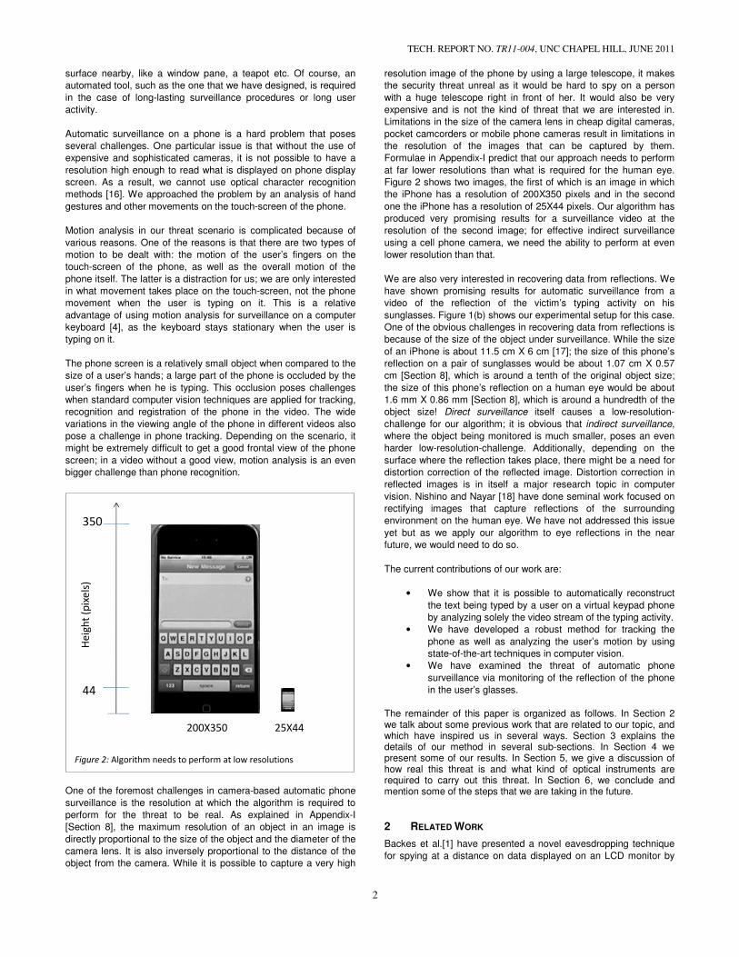
As shown in Figure 5, the distinguished regions { Dk } determined in
the surveillance image IK contain answers to questions like “Where
is the outline of the entire phone?”, “Where is the display screen of
the phone?”, and “Where are the keys in the keypad of the
phone?”. From the output of the tracking algorithm, we compute a
mask for the entire phone, henceforth called the phone mask
[Figure 15], which identifies the location of the phone in the image.
Algorithm 1: Track and Identify the Phone
Output: For every frame in the video, a vector of ellipses that
represent the location of the phone as well as location of
keys and other such features on the phone in that particular
frame
1: detect MSERs in the reference phone image IREF (say {Rref})
2: select a subset of MSERs in {Rref}, which are repeatable across
different surveillance scenarios. Let us name this subset
distinguished regions {Dref}.
3: for every image IK in the surveillance video do:
4: detect MSERs in the image IK (say {RK}).
5: match regions in {RK} to distinguished regions {Dref} in
the reference image and select those regions in {RK}
which have high match scores.
6: refine the output of step 5 by a model-based post-
processing method to finalize the distinguished regions
{DK}
{DK} contains the {phone location, keys location, keypad
lines, ...} in image IK
(a) Reference image (b) Surveillance image
Figure 5: Distinguished regions detected in the Reference image and
matched with those detected in a Surveillance image
Screen
middle
Phone
outline
Keys
Keypad
Lines

Additionally, we have observed that the keys in a QWERTY key
are arranged in horizontal lines. To take advantage of that
structure, we fit lines to the keys detected on the phon
surveillance image. These lines (henceforth referred to as
lines) help us get a stronger confidence on the location of the
keypad of the phone, and that is helpful because
events that we are primarily interested in take place in the keypad
area of the phone rather than the entire phone.
We have successfully employed our approach to detect the phone
in various surveillance scenarios [Figure 6] including the case in
which the video captures a reflection of the typing activity in a
person’s sunglasses. Once the phone has been identified and
located in the video, we now proceed to the next stage
would attempt to detect the “key pressed” events in a stabilize
stream.
3.3 Change detection by absolute differencing
At the resolution at which our approach is implemented
possible to find out what the user is typing by read
screen on the phone. We had to design an approach
on the analysis of the motion of the user’s fingers
that take place on the phone like the “key pops up” event
We decided to use one of the simplest yet very powerful methods
of motion and change detection, namely, the method of a
differencing. The general idea of absolute differencing
looking at the differences between two images of the same scene
taken at different times. The parts of the scene that
will look exactly the same in both images, and the
images come from the parts that have moved.
differences can determine where in the scene the motion took place
as well as what type of motion it was.
We compute a difference image by considering the
absolute differences. Let us consider the sequence of images
extracted from the video { I1, I2 … IM }. Let the absolute difference
images between each consecutive pair be the sequence {
DM-1 }, where,
Dn(x) = | In+1(x) – In(x) |, for every pixel x in the images
(a) Reference image (b) Direct surveillance
(c) Direct surveillance (d) Sunglass reflections
Figure 6: Distinguished regions detected in various scenarios.
TECH. REPORT NO. TR11-004, UNC CHAPEL HILL,
5
the keys in a QWERTY keypad
To take advantage of that
on the phone in the
. These lines (henceforth referred to as keypad
) help us get a stronger confidence on the location of the
because the “key pressed”
place in the keypad
to detect the phone
including the case in
which the video captures a reflection of the typing activity in a
Once the phone has been identified and
located in the video, we now proceed to the next stage in which we
would attempt to detect the “key pressed” events in a stabilized
Change detection by absolute differencing
is implemented, it is not
read it off the display
approach which relies
fingers and other events
the “key pops up” event [Figure 7].
We decided to use one of the simplest yet very powerful methods
the method of absolute
absolute differencing involves
between two images of the same scene
that were stationary
, and the differences in the
have moved. Analysis of these
determine where in the scene the motion took place
We compute a difference image by considering the pixel-wise
Let us consider the sequence of images
. Let the absolute difference
images between each consecutive pair be the sequence { D1, D2 …
in the images
An analysis of the difference image DK
motion that took place in the scene between the times
We begin our analysis by assuming that the phone
stationary in the video, that is, the user does not move the phone
while typing on it. We would later generalize the discussion to
involve the movement of the phone as well.
different types of motions or events leave
difference image.
In our experiments, we found out that the motion
phone area (for a phone with a virtual keypad
a very small number of categories:
• “Key pops up”: This is the event in which a key is pressed by
the user. In all virtual keypad phones, whenever a user
presses a key (say the letter T [Figure 7]
on the screen so that the user easily knows what he is typing.
• “Key pops down”: This is the event in which the key (say the
letter T) that popped up when the user pressed it pops down
so that the user can carry on with the typing activity.
• “Finger moves”: This is the event in which the user’s finger(s)
are moving in the phone area between the times when
presses the keys [Figure 9].
• “No movement”: This is the event that no movement occurs
inside the phone area. This takes place when the user pauses
while typing, or just before and after the message has been
typed.
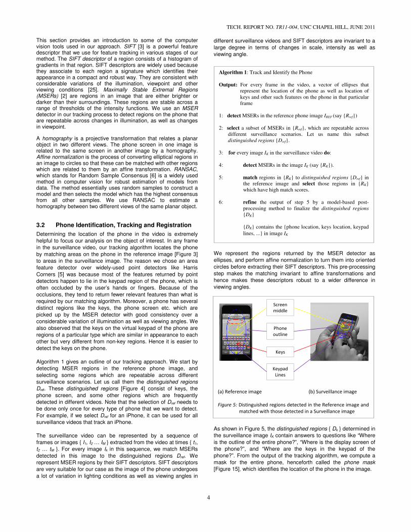
Figures 7, 8 and 9 show the difference images for the two most
significant events, the “key pops up” and the “finger moves” events
(a) Image Ik (b) Image Ik+1
Figure 8: Signature of a “key pops up event” for a Nexus One phone
(b) Direct surveillance
(d) Sunglass reflections
Distinguished regions detected in various scenarios.
(a) Image Ik (b) Image Ik+1
Figure 7: Signature of a “key pops up event” in the difference image
for an iPhone. The key T was pressed between the frames
(b) and (a) and (c) is the difference image that records this
motion.
UNC CHAPEL HILL, JUNE 2011
gives us a good idea of the
motion that took place in the scene between the times tK and tK+1.
We begin our analysis by assuming that the phone remains
the user does not move the phone
while typing on it. We would later generalize the discussion to
involve the movement of the phone as well. We observed that
f motions or events leave typical signatures in the
that the motion taking place in the
for a phone with a virtual keypad) can be classified into
: This is the event in which a key is pressed by
the user. In all virtual keypad phones, whenever a user
[Figure 7]), the letter T pops up
n so that the user easily knows what he is typing.
: This is the event in which the key (say the
) that popped up when the user pressed it pops down
so that the user can carry on with the typing activity.
event in which the user’s finger(s)
area between the times when he
: This is the event that no movement occurs
inside the phone area. This takes place when the user pauses
while typing, or just before and after the message has been
show the difference images for the two most
significant events, the “key pops up” and the “finger moves” events
(c) Difference image Dk
Signature of a “key pops up event” for a Nexus One phone
(c) Difference image Dk
Signature of a “key pops up event” in the difference image
was pressed between the frames
(b) and (a) and (c) is the difference image that records this
respectively. The signature of the “key pops down” event is very
similar to the “key pops up” event.
Thus, the process of detection of the “key pressed” event in the
sequence of frames {I1, I2 … IM} is reduced to the process of
detection of the “key pops up” event in the sequence of difference
images {D1, D2 …DM-1}. We use certain heuristics and parameters
to detect the “key pops up” event in the difference image
3.3.1 Detection of the “key pops up” event
The task of detecting whether a “key pops up” event
difference image Dk essentially involves searching
appearance in the image, This is accomplished by f
image Dk with an averaging filter and looking at the places
are local maxima of the filter output. If the filter output at one of
these maxima is within a certain range of value
empirically), a “key pops up” event occurs in this difference image
otherwise it does not. The following sections A and B
certain spatial as well as temporal data in the difference
sequence help us in searching for this event.
(a) Image Ik (b) Image Ik+1 (c) Difference image
Figure 9: Signature of a “finger moves” event. The finger moves over
the phone between the frames (a) and (b) and (c) is the
difference image that records this motion
Algorithm 2: Detect “key pops up” event in difference image
Output: Set of probable points in DK where this event occurs
Return NULL if no such point is found
1: filter DK with an averaging filter f, size(f) ∝ key_size
DK΄ = f ∗ DK,
2: calculate DK+1΄ and DK-1΄ as in step 1.
2: select a set of local maxima in the filtered output
this set {MK}.
3: for every point (xKi, yK
i) in MK do:
4: check if DK΄ (xKi, yK
i) is in the proper range.
5: check if the ratio ��΄ ���
�, � �
��� ΄ ����,
� � is in proper range.
6: check if the ratio ��΄ ���
�, � �
��� ΄ ����,
� � is in proper range.
7: if (xKi, yK
i) satisfies all three conditions {4, 5, 6}
8: add (xK
i, yKi) to the output.
TECH. REPORT NO. TR11-004, UNC CHAPEL HILL,
6
respectively. The signature of the “key pops down” event is very
, the process of detection of the “key pressed” event in the
} is reduced to the process of
up” event in the sequence of difference
heuristics and parameters
” event in the difference image sequence.
Detection of the “key pops up” event
“key pops up” event occurs in a
searching for a blob-like
This is accomplished by filtering the
at the places which
If the filter output at one of
values (determined
up” event occurs in this difference image;
A and B explain how
spatial as well as temporal data in the difference image
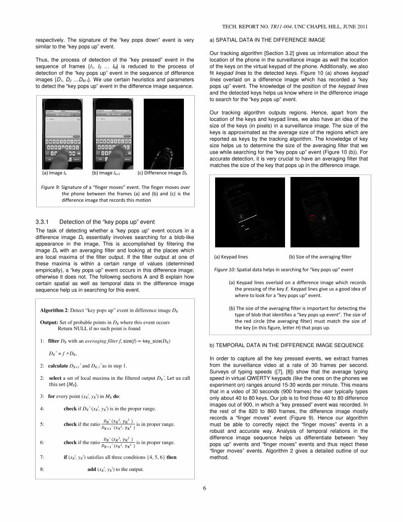
a) SPATIAL DATA IN THE DIFFERENCE IMAGE
Our tracking algorithm [Section 3.2] gives us information about the
location of the phone in the surveillance
of the keys on the virtual keypad of the phone
fit keypad lines to the detected keys. Figure 10
lines overlaid on a difference image which
pops up” event. The knowledge of the position of the
and the detected keys helps us know where
to search for the “key pops up” event.
Our tracking algorithm outputs regions.
location of the keys and keypad lines, we also have an idea of the
size of the keys (in pixels) in a surveillance image
keys is approximated as the average size of the regions
reported as keys by the tracking algorithm.
size helps us to determine the size of the averaging filter that we
use while searching for the “key pops up” event
accurate detection, it is very crucial to have an
matches the size of the key that pops up
b) TEMPORAL DATA IN THE DIFFERENCE IMAGE SEQUENCE
In order to capture all the key pressed events,
from the surveillance video at a rate of 30 frames per second.
Surveys of typing speeds ([7], [8]) show tha
speed in virtual QWERTY keypads (like the ones on the phones we
experiment on) ranges around 15-30 words per minute. This means
that in a video of 30 seconds (900 frames
only about 40 to 80 keys. Our job is to find those 40 to 8
images out of 900, in which a “key pressed” event was
the rest of the 820 to 860 frames, the difference image mostly
records a “finger moves” event (Figure 9)
must be able to correctly reject the “finger moves” events
robust and accurate way. Analysis of temporal relations in the
difference image sequence helps us
pops up” events and “finger moves” events and thus
“finger moves” events. Algorithm 2 gives a detailed outline of our
method.
(c) Difference image Dk
Signature of a “finger moves” event. The finger moves over
the phone between the frames (a) and (b) and (c) is the
difference image that records this motion
(a) Keypad lines (b) Size of the averaging filter
Figure 10: Spatial data helps in searching for “key pops up” event
(a) Keypad lines overlaid on a difference image which records
the pressing of the key E. Keypad lines give us a good idea of
where to look for a “key pops up”
(b) The size of the averaging filter is important for detecting the
type of blob that identifies a “key pops up event”. The size of
the red circle (the averaging filter) must match the size of
the key (in this figure, letter H) that pops up.
: Detect “key pops up” event in difference image DK
where this event occurs
key_size(DK)
a set of local maxima in the filtered output DK΄. Let us call
) is in the proper range.
is in proper range.
is in proper range.
) satisfies all three conditions {4, 5, 6} then
UNC CHAPEL HILL, JUNE 2011
SPATIAL DATA IN THE DIFFERENCE IMAGE
gives us information about the
surveillance image as well the location
of the phone. Additionally, we also
Figure 10 (a) shows keypad
which has recorded a “key
The knowledge of the position of the keypad lines
and the detected keys helps us know where in the difference image
regions. Hence, apart from the
we also have an idea of the
size of the keys (in pixels) in a surveillance image. The size of the
the average size of the regions which are
reported as keys by the tracking algorithm. The knowledge of key
size of the averaging filter that we
while searching for the “key pops up” event (Figure 10 (b)). For
have an averaging filter that
matches the size of the key that pops up in the difference image.
TEMPORAL DATA IN THE DIFFERENCE IMAGE SEQUENCE
In order to capture all the key pressed events, we extract frames
video at a rate of 30 frames per second.
show that the average typing
s (like the ones on the phones we
30 words per minute. This means
900 frames) the user typically types
ur job is to find those 40 to 80 difference
images out of 900, in which a “key pressed” event was recorded. In
0 frames, the difference image mostly
(Figure 9). Hence our algorithm
must be able to correctly reject the “finger moves” events in a
. Analysis of temporal relations in the
difference image sequence helps us differentiate between “key
nts and “finger moves” events and thus reject these
Algorithm 2 gives a detailed outline of our
ze of the averaging filter
Spatial data helps in searching for “key pops up” event
(a) Keypad lines overlaid on a difference image which records
. Keypad lines give us a good idea of
where to look for a “key pops up” event.
(b) The size of the averaging filter is important for detecting the
type of blob that identifies a “key pops up event”. The size of
the red circle (the averaging filter) must match the size of
) that pops up.

(a) (b)
Figure 11: Three successive difference images recording “finger
moves” events. These events are continuous in nature.
Figure 11 shows three successive frames that record “finger
moves” events. The moving of the finger over the phone is a
continuous event and hence is detected in many of the difference
images in the sequence.
Figure 12 shows three successive frames near a “key pops up”
event. The ‘key pops up’ and ‘key pops down’ events are sporadic
or episodic in nature. The key pops up in an instant, stays on for
some time (during which the difference image shows a zero
difference at the place where the key pops us) and then pops down
in an instant.
Thus, by examining the neighboring images in the
sequence, we are able to reject “finger moves” events and
higher confidence over the prediction of a “key pops up
process involves comparing the ratio of pixel values
averaging filter) in the blocks that represent the particular event in
the difference image DK with the pixel values at the same locations
in its time neighbors DK-1 and DK+1.
3.3.2 “Which key was pressed?”
Once a “key pops up” event has been recorded in a difference
image DK, our task now is to predict which key was pressed. While
template matching with the appearance of the key (in the difference
DK image or the image IK+1) seemed to be a promising idea initially,
as we started lowering the resolution of the images (for vide
surveillance from a distance or for surveillance on the reflections on
a sunglasses etc.), it was difficult to distinguish the keys from each
other based solely on their appearance. The scenario is shown in
the Figure 13, which shows images from two surv
that have captured the typing activity at a rather low resolution. In
13(a), the key R was pressed but template matching would give
(a) (b)
Figure 12: Three successive difference images near a “key pops up”
event. Image (b) records this event and (a) and (c) are the
nearby difference images.
TECH. REPORT NO. TR11-004, UNC CHAPEL HILL,
7
(c)
Three successive difference images recording “finger
moves” events. These events are continuous in nature.
Figure 11 shows three successive frames that record “finger
moves” events. The moving of the finger over the phone is a
s detected in many of the difference
Figure 12 shows three successive frames near a “key pops up”
event. The ‘key pops up’ and ‘key pops down’ events are sporadic
or episodic in nature. The key pops up in an instant, stays on for
ome time (during which the difference image shows a zero
difference at the place where the key pops us) and then pops down
Thus, by examining the neighboring images in the difference image
events and obtain a
pops up” event. The
process involves comparing the ratio of pixel values (after
in the blocks that represent the particular event in
el values at the same locations
Once a “key pops up” event has been recorded in a difference
, our task now is to predict which key was pressed. While
template matching with the appearance of the key (in the difference
) seemed to be a promising idea initially,
as we started lowering the resolution of the images (for video
surveillance from a distance or for surveillance on the reflections on
a sunglasses etc.), it was difficult to distinguish the keys from each
on their appearance. The scenario is shown in
the Figure 13, which shows images from two surveillance videos
that have captured the typing activity at a rather low resolution. In
was pressed but template matching would give
positive results for many letters that look like
(for example B, P, E, H, A). We decided that
which key was pressed was to look at the location of the
was detected in the difference image while searching for the “key
pops up” event.
Algorithm 3 gives an outline of our approach
computing the transformation that warps the
to the reference image IREF (details in Algorithm 4)
(c)
Three successive difference images near a “key pops up”
event. Image (b) records this event and (a) and (c) are the
Algorithm 3: Detect which key was pressed at the time
Input: i) The point (xK, yK) in the difference image
pops up” event has occurred.
ii) A keypad map for this phone that says where on the phone
screen a key pops up when that particular key is pressed
by the user.
Output: Set of probable letters that were pressed along with
respective probabilities.
Return NULL if no key was pressed at time
1: estimate a homography HK between the image
reference image IREF (details in Algorithm 4).
2: warp the difference image DK by the transformation
DK΄= DK * HK
(xK, yK) transforms to (xK΄, yK΄) under this transformation
2: perform posterior optimization via the steps 3 and 4.
(explained further in the Section 3.3.2)
3: for every key i in the keypad do:
4: ����� � �������������
��
p'(i) ∝ probability that key i was pressed
ai = area where key i pops up if it is pressed
aintersection = area of overlap between the blob at
(xK΄, yK΄) in DK
pops up if pressed
6: return NULL if aintersection = 0 for all keys
5: select the n keys with the highest probabilities
7: renormalize the probabilities to make them sum to 1 and
all the n (key, probability) pairs.
(a)
Figure 13: At low resolutions, it is difficult to predict which key was
pressed based on its appearance. So template matching fails
UNC CHAPEL HILL, JUNE 2011
positive results for many letters that look like R at that resolution
d that the best way to predict
s to look at the location of the blob that
while searching for the “key
our approach. We begin by
computing the transformation that warps the surveillance image IK
(details in Algorithm 4). We warp the
: Detect which key was pressed at the time tK
) in the difference image DK, where a “key
ii) A keypad map for this phone that says where on the phone
screen a key pops up when that particular key is pressed
Set of probable letters that were pressed along with
Return NULL if no key was pressed at time tK.
between the image IK and the
(details in Algorithm 4).
by the transformation HK to get
) under this transformation
posterior optimization via the steps 3 and 4.
(explained further in the Section 3.3.2)
was pressed
pops up if it is pressed
= area of overlap between the blob at
K΄ and the area where key i
pops up if pressed
= 0 for all keys
keys with the highest probabilities
the probabilities to make them sum to 1 and output
(b)
At low resolutions, it is difficult to predict which key was
pressed based on its appearance. So template matching fails

difference image DK by the same transformation to obtain a warped
difference image DK΄. We then perform posterior optimizati
determine which keys have the highest probabilities of being
pressed, given the warped difference image DK΄
yK΄) where the “key pops up” blob occurs. At this stage, we take
advantage of the fact that it is easy to obtain from a single
experiment, a map that says which region of the screen pops up
when a particular key is pressed on this phone.
For any key i in the keypad,
���/���� � ����� /�� ����
where, ���� = prior probability of the key i being pressed
���/���� = posterior probability of the key
given DK΄ and ( xK΄, yK΄)
����� /�� = probability the blob at ( xK΄, yK
key i has been pressed
= �������������
��
ai = area where key i pops up if it is pressed
map)
aintersection = area of overlap between the blob at (DK΄ and the area where key pressed
Based on formula (1) above, we compute the posterior probabilities
of keys by computing the ratio of areas of overlap.
overlap at all between the blob in the difference image and the
up” areas of the keys in the given map, we assume
pressed in this frame.
From the results of the posterior optimization, we could either
choose to output the one particular key with the highest probability
as the one being pressed or we could output a list of probable keys
and their corresponding probabilities. An example output of this
stage might look like “There is a 70% chance that an
pressed, and a 30% chance that it might have been an
exploring ways to utilize these probabilities by
probabilistic text processing method to refine the results of our
overall approach.
3.4 Image Alignment
Image alignment is one of the most crucial parts of our entire approach. The analysis in Section 3.3 of this paper assumes that the phone is stationary and all the events and motions are with respect to the phone. In a general scenario, while typing, the user moves the phone as well. In this case, the difference image between two consecutive frames in the video IKinformation about: • The overall motion of the phone and the hand(s) holding the
phone • The motion of the fingers in the phone area and the “key
pressed events” The first type of motion is a distraction for us as we are only interested in the motion that happens in the phone area.shows two consecutive images (a) and (b) (let us call them Ib) in the image sequence of a surveillance video. A “key pevent” occurs between the times ta and tb in the video.
TECH. REPORT NO. TR11-004, UNC CHAPEL HILL,
8
to obtain a warped
We then perform posterior optimization to
s have the highest probabilities of being
and the point (xK΄,
At this stage, we take
obtain from a single
says which region of the screen pops up
(1)
being pressed
terior probability of the key i being pressed
K΄) in DK΄ given that
pressed (given by the
area of overlap between the blob at (xK΄, yK΄) in and the area where key i pops up if
posterior probabilities
of keys by computing the ratio of areas of overlap. If there is no
overlap at all between the blob in the difference image and the “pop
in the given map, we assume that no key was
From the results of the posterior optimization, we could either
choose to output the one particular key with the highest probability
a list of probable keys
An example output of this
“There is a 70% chance that an E was
pressed, and a 30% chance that it might have been an R”. We are
exploring ways to utilize these probabilities by designing a
cessing method to refine the results of our
the most crucial parts of our entire of this paper assumes that
the phone is stationary and all the events and motions are with respect to the phone. In a general scenario, while typing, the user moves the phone as well. In this case, the difference image DK
K and IK+1 contains
The overall motion of the phone and the hand(s) holding the
The motion of the fingers in the phone area and the “key
The first type of motion is a distraction for us as we are only that happens in the phone area. Figure 14
shows two consecutive images (a) and (b) (let us call them Ia and ) in the image sequence of a surveillance video. A “key pressed
in the video. (c) is the
difference image between Ia and Ib calculated by taking the pixelwise differences in both images. We can clearly see the disturbance in the difference image caused by the slight moof the phone. In fact, detecting the “key pops up” event in the difference image (c) is very difficult. computed between images Ia and Ib’, where Isubjected to a transformation that aligns the phone area in image to the phone area in image Ia. It is evident that the difference image (d) is more meaningful for our analysis and also clearly shows the “key pops up” event in it.
Our tracking algorithm [Section 3.2] tells us the location of the
phone in the image and also returns the region that is occupied by
the phone in the image. From the output of this stage, a
mask is computed so that we mask out
surveillance image except the phone,
interest. The phone mask [Figure 15] plays a
image alignment process as this helps us find feature
exactly on the phone.
(a)
(c)
Figure 14: The need for image alignment.
(a) and (b) are two consecutive frames in a video. (c) is the
difference image between (a) and (b). (d) is the difference
image between (a) and (b) after aligning the phone area in
(b) to the phone area in (a).
(a)
Figure 15: Result of locating or masking the phone in an image
(a) Cropped image from surveillance video.
(b) Locating the phone in the image
UNC CHAPEL HILL, JUNE 2011
calculated by taking the pixel-wise differences in both images. We can clearly see the disturbance in the difference image caused by the slight movement of the phone. In fact, detecting the “key pops up” event in the
image (c) is very difficult. (d) is the difference image ’, where Ib’ is the image Ib
subjected to a transformation that aligns the phone area in image Ib . It is evident that the difference image
(d) is more meaningful for our analysis and also clearly shows the
tells us the location of the
phone in the image and also returns the region that is occupied by
From the output of this stage, a phone
is computed so that we mask out everything else in the
and focus on the object of
plays an important role in the
image alignment process as this helps us find features that lie
(b)
(d)
The need for image alignment.
(a) and (b) are two consecutive frames in a video. (c) is the
difference image between (a) and (b). (d) is the difference
image between (a) and (b) after aligning the phone area in
(b)
Result of locating or masking the phone in an image
(a) Cropped image from surveillance video.
(b) Locating the phone in the image (phone mask)
TECH. REPORT NO. TR11-004, UNC CHAPEL HILL, JUNE 2011
9
One of the initial ideas that we explored was to align the phone in
all the images in the surveillance video to the reference image of
the phone. This approach, while it seems to simplify the process a
lot, turned out to be a failure because of several reasons. One
apparent reason was that in many of the surveillance images, a
large part of the phone in occluded by the user’s hands; so there
weren’t enough correct correspondences to estimate a correct
transformation that warps the surveillance image to the reference
image. Another reason was that our method of absolute
differencing relies on the temporal relations between the video
frames. Hence, separately aligning each of the frames to the
reference image destroyed that temporal relation between
successive frames.
In our approach, before computing the difference image between
two successive images IK and IK+1, we align the phone areas in the
two images via SIFT matching. The very reason that we use only
features that lie on the phone makes sure that the warping between
these images stabilizes the phone area (so that the difference
images do not show the movement of the phone).
An important requirement of image alignment occurs at the stage
where we determine which key was pressed by the user, once a
“key pops up” event has been detected. The first step in Algorithm
3 is to align the surveillance image IK to the reference image IREF by
a homography HK. Computing this homography turns out to be a
challenging task as the user’s fingers obstruct a large part of the
phone’s keypad in a “key pressed” frame. These occlusions,
coupled with wide differences in illumination and viewing angle
often lead to incorrect homographies being computed between the
IK and IREF. Algorithm 4 describes the method of alignment that we
designed to overcome this challenge.
Instead of directly aligning the image IK (called the target frame) to
IREF, we first choose an image ICF (called the clear frame) in the
same video that has an unobstructed view of the phone keypad. To
find this image, we again use the output of our tracking method
(Section 3.2) which also returns the number of keys detected in
each surveillance image in the video. If more number of keys were
detected, that image has a more unobstructed view of the keypad.
We then compute a homography between the reference image and
the clear frame. This homography would be accurate because we
have an unobstructed view of the keypad and hence there would be
reliable feature matches between the two images. The next step is
to estimate a homography between the target frame and the clear
frame. This homography would also be correct as both images are
from the same video and have roughly the same lighting conditions
and viewing angles. The final homography that we require is just a
multiplication of the two homographies just computed.
4 RESULTS
For our experiments, we used a Canon Vixia HG 21 Camcorder
(costs about 1000 USD). The experiments were conducted in an
indoor environment, and the camera was at a distance of 2 to 3
meters from the user.
4.1 Direct surveillance with no phone movement
We conducted our first set of experiments keeping the phone stable
(hence not moving) while the user types on it. The experiments
were performed on a direct surveillance setup where the camera
had an unobstructed view of the phone and was at a distance of
about 2 meters from the user. The results we obtained for these
surveillance videos were excellent and showed promise that our
algorithm was ready to be applied to more challenging scenarios.
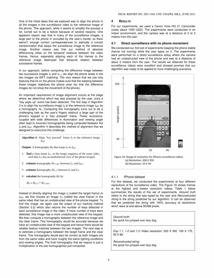
4.1.1 iPhone dataset
For this dataset, we conducted the experiments at four different
resolutions of the surveillance video. The Figure 16 shows frames
at the highest and lowest resolution videos. Table 1 below
summarizes the results of this set of experiments. Ground truth
refers to the string that was typed by the user and Reconstructed
string is the string predicted by our algorithm. It can be observed
that we predicted the string with 100% accuracy at resolutions
which were at and above 50X88 pixels.
Ground truth:
the quick fox jumped over lazy dog
Exp 1.1, 1.2 and 1.3: Video resolution: 200 X 350, 100 X 175,
50 X 88
Reconstructed string:
the quick fox jumped over lazy dog
Algorithm 4: Align “key pressed” frame IK to the reference image
IREF
Output: A homography HK that warps IK to IREF
1: find a clear frame ICF, in the image sequence of the same video,
such that ICF has an unobstructed view of the phone keypad.
2: estimate homography HCF-REF between ICF and IREF.
3: estimate homography HK-CF between IK and ICF.
4: calculate the homography HK by:
HK = HK-CF * HCF-REF
(a) (b)
Figure 16: Range of resolution for iPhone surveillance videos
(a) Resolution: 200 X 350
(b) Resolution: 25 X 44
350
44
He
igh
t (p
ixe
ls)
TECH. REPORT NO. TR11-004, UNC CHAPEL HILL, JUNE 2011
10
Exp 1.4: Video resolution: 25 X 44
Reconstructed string:
the quick fox jumpedxlovder nlazy dog
Table 1: Results of experiments for the iPhone dataset
In the case Exp 1.4, in which the input video had a resolution of
25X44 pixels [Figure 16(b)], our algorithm still predicted most parts
of the string correctly. In terms of the number of frames that fired as
“key pressed events”, there is a false positive rate of 11 % and no
false negatives. The Levenshtein Edit Distance between the
Reconstructed string and the Ground truth is 5 characters. Based
on this measure, there is an error rate of 14% per character for Exp
1.4. Another popular measure used for evaluation of Machine
Translation is Word Error Rate (WER), which is based on the
normalized Levenshtein edit distance between the hypothesis and
the reference, assuming a word as the basic unit of comparison.
The WER in case of Exp 1.4 turns out to be (2/7). It is interesting to
note that at the resolution at which Exp 1.4 was recorded [Figure
16(b)], it is not possible for a human being to predict the user-typed
string by watching the video.
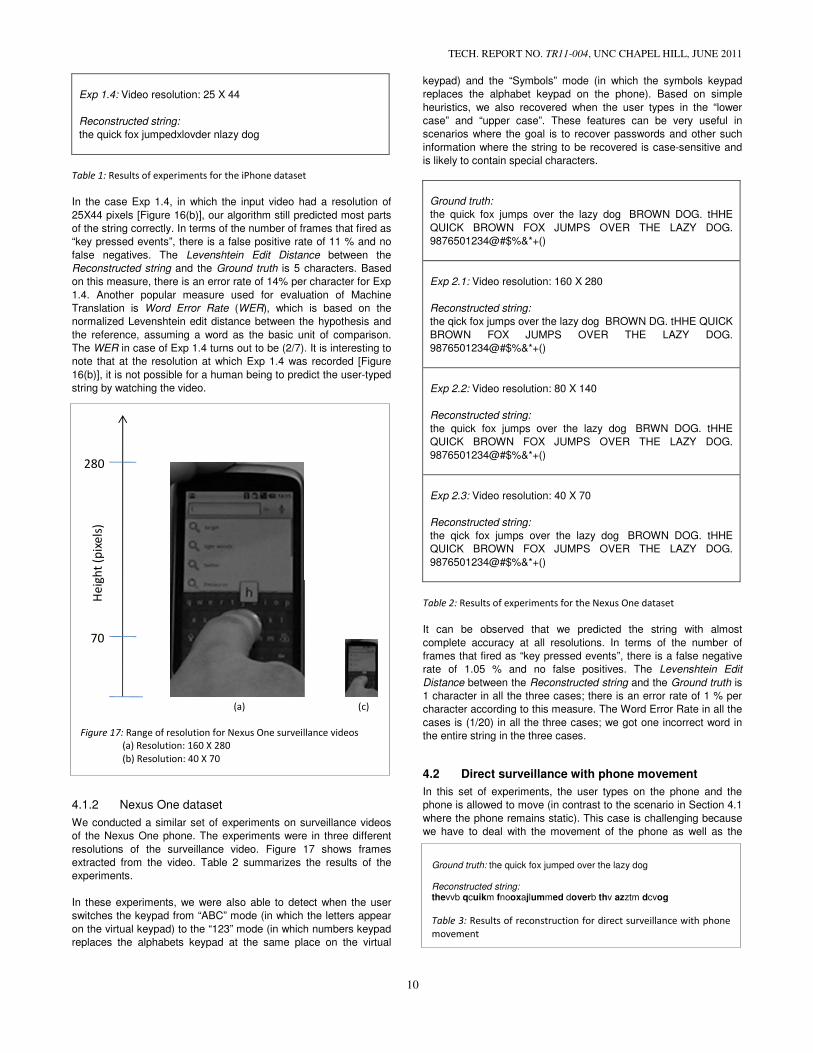
4.1.2 Nexus One dataset
We conducted a similar set of experiments on surveillance videos
of the Nexus One phone. The experiments were in three different
resolutions of the surveillance video. Figure 17 shows frames
extracted from the video. Table 2 summarizes the results of the
experiments.
In these experiments, we were also able to detect when the user
switches the keypad from “ABC” mode (in which the letters appear
on the virtual keypad) to the “123” mode (in which numbers keypad
replaces the alphabets keypad at the same place on the virtual
keypad) and the “Symbols” mode (in which the symbols keypad
replaces the alphabet keypad on the phone). Based on simple
heuristics, we also recovered when the user types in the “lower
case” and “upper case”. These features can be very useful in
scenarios where the goal is to recover passwords and other such
information where the string to be recovered is case-sensitive and
is likely to contain special characters.
Ground truth:
the quick fox jumps over the lazy dog BROWN DOG. tHHE
QUICK BROWN FOX JUMPS OVER THE LAZY DOG.
9876501234@#$%&*+()
Exp 2.1: Video resolution: 160 X 280
Reconstructed string:
the qick fox jumps over the lazy dog BROWN DG. tHHE QUICK
BROWN FOX JUMPS OVER THE LAZY DOG.
9876501234@#$%&*+()
Exp 2.2: Video resolution: 80 X 140
Reconstructed string:
the quick fox jumps over the lazy dog BRWN DOG. tHHE
QUICK BROWN FOX JUMPS OVER THE LAZY DOG.
9876501234@#$%&*+()
Exp 2.3: Video resolution: 40 X 70
Reconstructed string:
the qick fox jumps over the lazy dog BROWN DOG. tHHE
QUICK BROWN FOX JUMPS OVER THE LAZY DOG.
9876501234@#$%&*+()
Table 2: Results of experiments for the Nexus One dataset
It can be observed that we predicted the string with almost
complete accuracy at all resolutions. In terms of the number of
frames that fired as “key pressed events”, there is a false negative
rate of 1.05 % and no false positives. The Levenshtein Edit
Distance between the Reconstructed string and the Ground truth is
1 character in all the three cases; there is an error rate of 1 % per
character according to this measure. The Word Error Rate in all the
cases is (1/20) in all the three cases; we got one incorrect word in
the entire string in the three cases.
4.2 Direct surveillance with phone movement
In this set of experiments, the user types on the phone and the
phone is allowed to move (in contrast to the scenario in Section 4.1
where the phone remains static). This case is challenging because
we have to deal with the movement of the phone as well as the
(a) (c)
Figure 17: Range of resolution for Nexus One surveillance videos
(a) Resolution: 160 X 280
(b) Resolution: 40 X 70
280
70
He
igh
t (p
ixe
ls)
Ground truth: the quick fox jumped over the lazy dog Reconstructed string: thevvb qcuikm fnooxajlummed doverb thv azztm dcvog
Table 3: Results of reconstruction for direct surveillance with phone
movement
movement of the user’s fingers in the phone area.
Table 3 shows the results of our algorithm on one surveillance
video. The bold letters in the reconstructed string are the correctly
detected letters. There is a rather large quantity of false positive
“key pressed events”, around 50%, because of which
string does not make any sense. The number of false negatives is
around 10%. The Levenshtein Edit Distance between the
truth and Reconstructed string is 19 characters, which is also pretty
large considering that the length of the input string is only
characters. However, in terms of the number of
Ground truth that were recovered in their correct relative order in
the Reconstructed string, we have an accuracy of
out of the 29 characters typed by the user have been detected
their correct order by the algorithm. A number of false positives can
be reduced by manipulating the parameters of our
detection algorithm. A language model based post
would be very helpful in predicting the user-typed
accuracy. In the keyboard surveillance method proposed by
Balzarotti et al [4], a major part of their approach is language
modeling and text analysis to reproduce what was being typed o
the keyboard.
For each “key pressed” event, instead of storing
(for example, the user has pressed the letter E), we store
probable characters with their respective probabilit
there is a 55% chance that an E has been pressed, but a 45%
chance that it might actually have been an R; the
are next to each other in the phone keypad).
obtaining these probabilities is explained in Sectio
3]. The reconstructed string shown in Table 3 shows only the most
probable outputs for each letter. We are in the process of exploring
ways to use these probabilities meaningfully to produce a correct
output string.
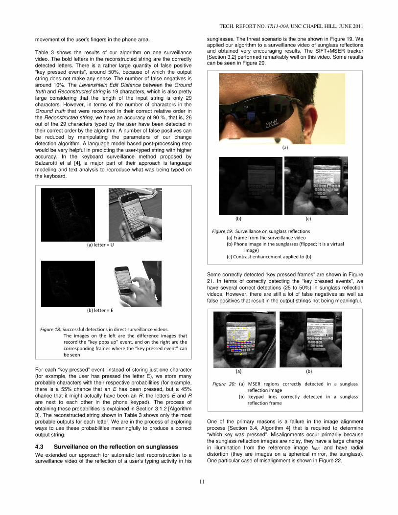
4.3 Surveillance on the reflection on sunglasses
We extended our approach for automatic text reconstruction to a surveillance video of the reflection of a user’s typing activity in his
(a) letter = U
(b) letter = E
Figure 18: Successful detections in direct surveillance videos.
The images on the left are the difference images that
record the “key pops up” event, and on the right
corresponding frames where the “key pressed event” can
be seen
TECH. REPORT NO. TR11-004, UNC CHAPEL HILL,
11
fingers in the phone area.
algorithm on one surveillance
The bold letters in the reconstructed string are the correctly
There is a rather large quantity of false positive
of which the output
. The number of false negatives is
between the Ground
, which is also pretty
g that the length of the input string is only 29
number of characters in the
hat were recovered in their correct relative order in
have an accuracy of 90 %, that is, 26
have been detected in
number of false positives can
be reduced by manipulating the parameters of our change
post-processing step
typed string with higher
. In the keyboard surveillance method proposed by
Balzarotti et al [4], a major part of their approach is language
modeling and text analysis to reproduce what was being typed on
just one character
letter E), we store many
respective probabilities (for example,
has been pressed, but a 45%
; the letters E and R
in the phone keypad). The process of
probabilities is explained in Section 3.1.2 [Algorithm
The reconstructed string shown in Table 3 shows only the most
probable outputs for each letter. We are in the process of exploring
ways to use these probabilities meaningfully to produce a correct
eflection on sunglasses
automatic text reconstruction to a the reflection of a user’s typing activity in his
sunglasses. The threat scenario is the one shown in Figure 19. We applied our algorithm to a surveillance video of sunglass reflections and obtained very encouraging results.[Section 3.2] performed remarkably well on this video. Some results can be seen in Figure 20.
Some correctly detected “key pressed frames” are shown in Figure
21. In terms of correctly detecting the
have several correct detections (25 to 50%) in sunglass ref
videos. However, there are still a lot of false negatives as well as
false positives that result in the output string
One of the primary reasons is a failure in the image alignm
process [Section 3.4, Algorithm 4] that is
“which key was pressed”. Misalignments occur primarily because
the sunglass reflection images are noisy,
in illumination from the reference image
distortion (they are images on a spherical mirror, the sunglass)
One particular case of misalignment is shown in Figure 22.
(a)
Figure 20: (a) MSER regions correctly detected in a sunglass
reflection image
(b) keypad lines correctly detected in a sunglass
reflection frame
(a)
(b)
Figure 19: Surveillance on sunglass reflections
(a) Frame from the surveillance video
(b) Phone image in the sunglasses (flipped; it is a virtual
image)
(c) Contrast enhancement applied to (b)
Successful detections in direct surveillance videos.
The images on the left are the difference images that
record the “key pops up” event, and on the right are the
corresponding frames where the “key pressed event” can
UNC CHAPEL HILL, JUNE 2011
sunglasses. The threat scenario is the one shown in Figure 19. We surveillance video of sunglass reflections
and obtained very encouraging results. The SIFT+MSER tracker performed remarkably well on this video. Some results
“key pressed frames” are shown in Figure
the “key pressed events”, we
correct detections (25 to 50%) in sunglass reflection
there are still a lot of false negatives as well as
false positives that result in the output strings not being meaningful.
failure in the image alignment
that is required to determine
Misalignments occur primarily because
sunglass reflection images are noisy, they have a large change
in illumination from the reference image IREF, and have radial
distortion (they are images on a spherical mirror, the sunglass).
is shown in Figure 22.
(b)
ly detected in a sunglass
(b) keypad lines correctly detected in a sunglass
(c)
Surveillance on sunglass reflections
(a) Frame from the surveillance video
(b) Phone image in the sunglasses (flipped; it is a virtual
Contrast enhancement applied to (b)

5 HOW REAL IS THE THREAT? (PRACTICAL LIMITS
In Appendix – I [Section 8] we provide a discussion on
parameters if this threat was to be planned in a real scenario.
following is a discussion based on the results of that analysis.
5.1 How good are current equipments
In Section 8, we saw that the maximum resolution with which a particular object can be captured by a camera depends upon
• The diameter of its lens • Distance of object from the camera
For our algorithm, we have demonstrated successful results even at an object resolution 25 X 44 (pixels in each dimension) (for the iPhone). This was in the case when the phone was static, but in the general cases we have promising results with resolutions around 100 X 175. By the expression (3) [Section 8.2.1], the minimum diameter of a lens required to directly capture the typing activity of the phone at the resolution of 100 X 175 from a distance of 1 metThe diameter of most good cell phone cameras (iPhone, Nexus One etc.) is in the range of 1.3 to 1.5 mm. This implies that if Ali
(a) letter = E
(c) letter = G
Figure 21: Correct detection of keys pressed in sunglass reflection
video.The images on the left are the difference images
that record the “key pops up” event, and on the right are
the corresponding frames where the “key pressed event”
can be seen.
(a) (b)
Figure 22: Misalignment of sunglass frames.
(c) is the phone in (b) aligned with the reference image (a).
(a) is the IREF, and we can see that the aligned image (c) is
distorted.
TECH. REPORT NO. TR11-004, UNC CHAPEL HILL,
12
PRACTICAL LIMITS)
a discussion on the relevant
in a real scenario. The
based on the results of that analysis.
How good are current equipments
, we saw that the maximum resolution with which a particular object can be captured by a camera depends upon
For our algorithm, we have demonstrated successful results even at an object resolution 25 X 44 (pixels in each dimension) (for the iPhone). This was in the case when the phone was static, but in the
cases we have promising results with resolutions around
, the minimum diameter of a lens required to directly capture the typing activity of the phone at the resolution of 100 X 175 from a distance of 1 meter is 1.16 mm.
ost good cell phone cameras (iPhone, Nexus One etc.) is in the range of 1.3 to 1.5 mm. This implies that if Alice
is at a distance of around 1 m from Bob, and has an unobstructed view of Bob’s phone she can get an automated transcript of what Bob is typing by recording a video from her own cell phone itself. This can very easily take place in a crowded place like a bus or a metro train. The diameter of most cheap digital cameras (under 200 USD)ranges from 2.0 to 6.0 mm; they can effectively spy from a distance of 1 to 4 meters from the typing user. The diameter of slightly high price range (under 500 USD) digital cameras ranges up to 20 mm; they can be used to spy upon the person up to distances of 10 m or more.
Figure 23 and Figure 24 provide an approximate range at which direct and indirect surveillance can be carried out using our algorithm with the use of different types of cameras. overhead surveillance cameras and such equipdirectly spy on the phone user whereas high quality cameras and telescopes would be required to spy on the eye from distances of 5 m or more. Tthat the threat that we examine is real and using moderately priced equipment in a real life setting.
6 CONCLUSION
Through our current work, we have shown thatreconstruction solely from a surveillance video is possible for eavesdropping on a smart phone. We have developed a method for tracking and identifying a phone that has been successfulrange of surveillance videos. This algorithm has performed remarkably well even when we applied it for tracking thvideo that captured a reflection of the phone in the user’s sunglasses. Based on an analysis of optical parametersequipments, we have predicted that automatic spying on a phoneuser is a potential threat that could be carried outavailable cameras using state-ofalgorithms. There are several possible directions in which carried out in this area. For further improvement of our spying
Correct detection of keys pressed in sunglass reflection
video.The images on the left are the difference images
that record the “key pops up” event, and on the right are
the corresponding frames where the “key pressed event”
(c)
reference image (a).
, and we can see that the aligned image (c) is
(a) 2 m (b) 4 m (c) 3 m
Figure 23: Approximate spying range for
(a) Cell phone camera/pocket camcorders (~100 USD)
(b) Cheap digital cameras (~150 USD)
(c) Cheap surveillance cameras (~150 USD)
(d) SLR cameras (~500 USD)
(a) 2 m (b) 5 m (c) 15 m
Figure 24: Approximate spying range for
reflections in glasses / sunglasses
(a) SLR cameras (~500 USD)
(b) HD Camcorders (~1000 USD)
(c) Cheap telescopes (~700 USD)
UNC CHAPEL HILL, JUNE 2011
1 m from Bob, and has an unobstructed view of Bob’s phone she can get an automated transcript of what
by recording a video from her own cell phone itself. This can very easily take place in a crowded place like a bus or a
The diameter of most cheap digital cameras (under 200 USD) hey can effectively spy from a distance
of 1 to 4 meters from the typing user. The diameter of slightly high tal cameras ranges up to 20 mm;
they can be used to spy upon the person up to distances of 10 m or
provide an approximate range at which direct and indirect surveillance can be carried out using our algorithm with the use of different types of cameras. Thus, overhead surveillance cameras and such equipments can easily
whereas high quality cameras and e required to spy on the reflection on glasses or
The analysis above predicts threat that we examine is real and could be carried out
moderately priced equipment in a real life setting.
Through our current work, we have shown that automatic text solely from a surveillance video is possible for
We have developed a method for that has been successful in a wide
range of surveillance videos. This algorithm has performed remarkably well even when we applied it for tracking the phone in a
ion of the phone in the user’s an analysis of optical parameters and optical
, we have predicted that automatic spying on a phone that could be carried out with readily
of-the-art computer vision
There are several possible directions in which future work could be For further improvement of our spying
(d) 15 m
Approximate spying range for direct surveillance
(a) Cell phone camera/pocket camcorders (~100 USD)
(b) Cheap digital cameras (~150 USD)
(c) Cheap surveillance cameras (~150 USD)
(b) 5 m (c) 15 m
Approximate spying range for indirect surveillance from
reflections in glasses / sunglasses
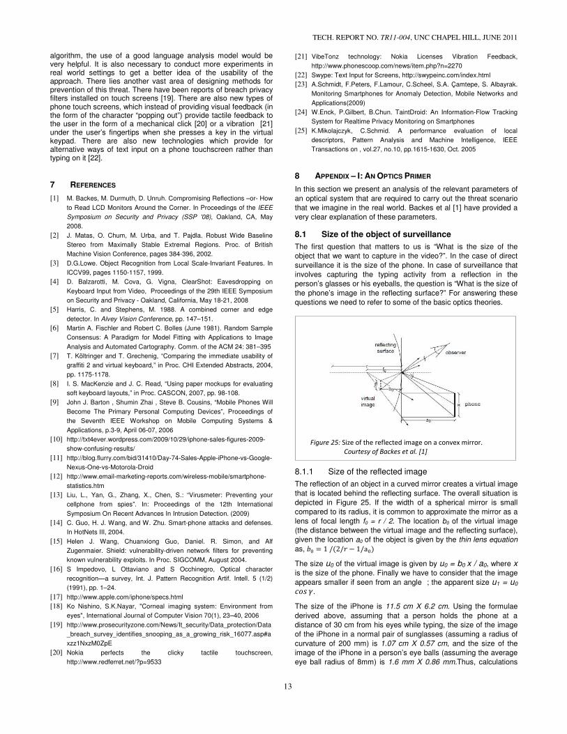
TECH. REPORT NO. TR11-004, UNC CHAPEL HILL, JUNE 2011
13
algorithm, the use of a good language analysis model would be very helpful. It is also necessary to conduct more experiments in real world settings to get a better idea of the usability of the approach. There lies another vast area of designing methods for prevention of this threat. There have been reports of breach privacy filters installed on touch screens [19]. There are also new types of phone touch screens, which instead of providing visual feedback (in the form of the character “popping out”) provide tactile feedback to the user in the form of a mechanical click [20] or a vibration [21] under the user’s fingertips when she presses a key in the virtual keypad. There are also new technologies which provide for alternative ways of text input on a phone touchscreen rather than typing on it [22].
7 REFERENCES
[1] M. Backes, M. Durmuth, D. Unruh. Compromising Reflections –or- How
to Read LCD Monitors Around the Corner. In Proceedings of the IEEE
Symposium on Security and Privacy (SSP '08), Oakland, CA, May
2008.
[2] J. Matas, O. Chum, M. Urba, and T. Pajdla. Robust Wide Baseline
Stereo from Maximally Stable Extremal Regions. Proc. of British
Machine Vision Conference, pages 384-396, 2002.
[3] D.G.Lowe. Object Recognition from Local Scale-Invariant Features. In
ICCV99, pages 1150-1157, 1999.
[4] D. Balzarotti, M. Cova, G. Vigna, ClearShot: Eavesdropping on
Keyboard Input from Video, Proceedings of the 29th IEEE Symposium
on Security and Privacy - Oakland, California, May 18-21, 2008
[5] Harris, C. and Stephens, M. 1988. A combined corner and edge
detector. In Alvey Vision Conference, pp. 147–151.
[6] Martin A. Fischler and Robert C. Bolles (June 1981). Random Sample
Consensus: A Paradigm for Model Fitting with Applications to Image
Analysis and Automated Cartography. Comm. of the ACM 24: 381–395
[7] T. Költringer and T. Grechenig, “Comparing the immediate usability of
graffiti 2 and virtual keyboard,” in Proc. CHI Extended Abstracts, 2004,
pp. 1175-1178.
[8] I. S. MacKenzie and J. C. Read, “Using paper mockups for evaluating
soft keyboard layouts,” in Proc. CASCON, 2007, pp. 98-108.
[9] John J. Barton , Shumin Zhai , Steve B. Cousins, “Mobile Phones Will
Become The Primary Personal Computing Devices”, Proceedings of
the Seventh IEEE Workshop on Mobile Computing Systems &
Applications, p.3-9, April 06-07, 2006
[10] http://txt4ever.wordpress.com/2009/10/29/iphone-sales-figures-2009-
show-confusing-results/
[11] http://blog.flurry.com/bid/31410/Day-74-Sales-Apple-iPhone-vs-Google-
Nexus-One-vs-Motorola-Droid
[12] http://www.email-marketing-reports.com/wireless-mobile/smartphone-
statistics.htm
[13] Liu, L., Yan, G., Zhang, X., Chen, S.: “Virusmeter: Preventing your
cellphone from spies”. In: Proceedings of the 12th International
Symposium On Recent Advances In Intrusion Detection. (2009)
[14] C. Guo, H. J. Wang, and W. Zhu. Smart-phone attacks and defenses.
In HotNets III, 2004.
[15] Helen J. Wang, Chuanxiong Guo, Daniel. R. Simon, and Alf
Zugenmaier. Shield: vulnerability-driven network filters for preventing
known vulnerability exploits. In Proc. SIGCOMM, August 2004.
[16] S Impedovo, L Ottaviano and S Occhinegro, Optical character
recognition—a survey, Int. J. Pattern Recognition Artif. Intell. 5 (1/2)
(1991), pp. 1–24.
[17] http://www.apple.com/iphone/specs.html
[18] Ko Nishino, S.K.Nayar, "Corneal imaging system: Environment from
eyes", International Journal of Computer Vision 70(1), 23–40, 2006
[19] http://www.prosecurityzone.com/News/It_security/Data_protection/Data
_breach_survey_identifies_snooping_as_a_growing_risk_16077.asp#a
xzz1NxzM0ZpE
[20] Nokia perfects the clicky tactile touchscreen,
http://www.redferret.net/?p=9533
[21] VibeTonz technology: Nokia Licenses Vibration Feedback,
http://www.phonescoop.com/news/item.php?n=2270
[22] Swype: Text Input for Screens, http://swypeinc.com/index.html
[23] A.Schmidt, F.Peters, F.Lamour, C.Scheel, S.A. Çamtepe, S. Albayrak.
Monitoring Smartphones for Anomaly Detection, Mobile Networks and
Applications(2009)
[24] W.Enck, P.Gilbert, B.Chun. TaintDroid: An Information-Flow Tracking
System for Realtime Privacy Monitoring on Smartphones
[25] K.Mikolajczyk, C.Schmid. A performance evaluation of local
descriptors, Pattern Analysis and Machine Intelligence, IEEE
Transactions on , vol.27, no.10, pp.1615-1630, Oct. 2005
8 APPENDIX – I: AN OPTICS PRIMER
In this section we present an analysis of the relevant parameters of
an optical system that are required to carry out the threat scenario
that we imagine in the real world. Backes et al [1] have provided a
very clear explanation of these parameters.
8.1 Size of the object of surveillance
The first question that matters to us is “What is the size of the
object that we want to capture in the video?”. In the case of direct
surveillance it is the size of the phone. In case of surveillance that
involves capturing the typing activity from a reflection in the
person’s glasses or his eyeballs, the question is “What is the size of
the phone’s image in the reflecting surface?” For answering these
questions we need to refer to some of the basic optics theories.
8.1.1 Size of the reflected image
The reflection of an object in a curved mirror creates a virtual image
that is located behind the reflecting surface. The overall situation is
depicted in Figure 25. If the width of a spherical mirror is small
compared to its radius, it is common to approximate the mirror as a
lens of focal length f0 = r / 2. The location b0 of the virtual image
(the distance between the virtual image and the reflecting surface),
given the location a0 of the object is given by the thin lens equation
as, !" � 1 /(2/% − 1/a")
The size u0 of the virtual image is given by u0 = b0 x / a0, where x
is the size of the phone. Finally we have to consider that the image
appears smaller if seen from an angle ; the apparent size u1 = u0
()* +.
The size of the iPhone is 11.5 cm X 6.2 cm. Using the formulae
derived above, assuming that a person holds the phone at a
distance of 30 cm from his eyes while typing, the size of the image
of the iPhone in a normal pair of sunglasses (assuming a radius of
curvature of 200 mm) is 1.07 cm X 0.57 cm, and the size of the
image of the iPhone in a person’s eye balls (assuming the average
eye ball radius of 8mm) is 1.6 mm X 0.86 mm.Thus, calculations
Figure 25: Size of the reflected image on a convex mirror.
Courtesy of Backes et al. [1]

TECH. REPORT NO. TR11-004, UNC CHAPEL HILL, JUNE 2011
14
reveal that the image of the phone in a person’s glasses is about a
tenth of the actual size, and the size of the image of the phone in
his eyes is about a hundredth of the actual size.
8.2 Limits of optical resolution
Some relevant questions are, “Is it feasible to conduct the video surveillance on another phone by using the camera in my phone?”, “How powerful a camera do I need to make the automatic detection work on the reflection of the typing activity in another person’s sunglasses or eyes?”. For answering all these questions, we first need to understand the term “Optical resolution”.
Let the distance from the camera to the object being captured be ,. The object might be the phone or its reflection on some surface. Let
- be the required resolution of this object on the camera image (in
pixels). If the size of the object is ./, then the optical resolution 0
(in radians) required to capture the object with the desired
resolution in the image is given by,
0 = 1%(21-( .1/-, ) ≈ .1 / -, (1)
where the approximation holds as .1 ≪ ,.
8.2.1 Diffraction Bounds
Diffraction is a physical phenomenon that diffuses light or any other
electromagnetic wave, whenever it passes some aperture. Though
this phenomenon is well-known for being visible to the human eye
for very small apertures, in case of high magnifications, it is
noticeable even for large apertures like lenses used in cameras and
telescopes. In fact, as we will see further in this discussion,
diffraction constitutes one of the most limiting parameters in the use
of cameras for surveillance scenarios.
The influence of diffraction on the maximum optical resolution of a
telescope is given by Rayleigh’s criterion. Let two point sources P1,
P2 be given such that the angle between these two sources is 0 (in
radians). Let D be the diameter of the lens of the camera and 5 the
wavelength of the light. Then Raleigh’s criterion states that the two
points P1, P2 can be distinguished if and only if
0 ≥ 1.22 5/� (2)
From equations (1) and (2), we can derive an expression for the
maximum resolution of an object that can be captured by a camera
lens at a given distance. The expression is:
n ≤ ./D/(1.22 λ d) (3)
From the expression above, it is apparent that the maximum
resolution that can be captured by a camera or telescope lens is
directly proportional to the diameter of the lens, and inversely
proportional to the distance between the camera and the object.