Embed Size (px)
Citation preview

INSTALLATION ANDOPERATION INSTRUCTIONS
Map Guide TM

Copyright © 1996, 1997, 1998 Eagle ElectronicsAll rights reserved.
Map Guide™ is a trademark of Eagle ElectronicsEagle® is a registered trademark of Eagle Electronics
WARNING!USE THIS UNIT ONLY AS AN AID TO NAVIGATION. A CAREFUL NAVI-GATOR NEVER RELIES ON ONLY ONE METHOD TO OBTAIN POSI-TION INFORMATION.
Never use this product while operating a vehicle.
CAUTIONWhen showing navigation data to a position (waypoint), this unit will showthe shortest, most direct path to the waypoint. It provides navigation datato the waypoint regardless of obstructions. Therefore, the prudent naviga-tor will not only take advantage of all available navigation tools when trav-elling to a waypoint, but will also visually check to make certain a clear,safe path to the waypoint is always available.
The operating and storage temperature for your unit is from -4 degrees to+167 degrees Fahrenheit (-20 to +75 degrees Celsius). Extended storagetemperatures higher or lower than specified will cause the liquid crystaldisplay to fail. Neither this type of failure nor its consequences are cov-ered by the warranty. For more information, consult the factory customerservice department.
All features and specifications subject to change without notice.
Eagle Electronics may find it necessary to change or end our policies,regulations, and special offers at any time. We reserve the right to do sowithout notice.
All screens in this manual are simulated.

This device complies with Part 15 of the FCC Rules. Operation is subjectto the following two conditions: (1) this device may not cause harmfulinterference, and (2) this device must accept any interference received,including interference that may cause undesired operation.
Note:This equipment has been tested and found to comply with the limits for aClass B digital device, pursuant to Part 15 of the FCC Rules. These limitsare designed to provide reasonable protection against harmful interfer-ence in a residential installation. This equipment generates, uses and canradiate radio frequency energy and, if not installed and used in accor-dance with the instructions, may cause harmful interference to radio com-munications. However, there is no guarantee that interference will not oc-cur in a particular installation. If this equipment does cause harmful inter-ference to radio or television reception, which can be determined by turn-ing the equipment off and on, the user is encouraged to try to correct theinterference by one or more of the following measures:
• Reorient or relocate the receiving antenna.• Increase the separation between the equipment and receiver.• Connect the equipment into an outlet on a circuit different from that to
which the receiver is connected.• Consult the factory customer service department for help.
SpecificationsDimensions ................................................. 6.75” L x 2.25” W x 1.625” DDisplay .................................................................. 160 H x 104 W pixelsPower ....................................................................................... 5-35 vdcWaypoints ......................................................................................... 750Routes ................................................................................................ 99Waypoints per Route (maximum) ........................................................ 99Total Waypoints used in Routes ...................................................... 1500Icons ............................................................................................... 1000Savable Plot Trails................................................................................. 3Maximum Plot Trail Points .................................................. 3000 per trail
INTRODUCTION ............................................................................................................1S/A - What is it? .......................................................................................................2Don’t Get Lost ..........................................................................................................2
GETTING STARTED ......................................................................................................3Power .................................................................................................................3BATTERIES ..............................................................................................................3
Battery Installation .............................................................................................3NiMH Battery .....................................................................................................3
OPERATION .................................................................................................................4Keyboard .................................................................................................................4Menus .................................................................................................................4Turning Power On ....................................................................................................5Satellite Status Screen ............................................................................................5Finding Your Position ................................................................................................6
Auto Search .......................................................................................................6Manual Initialization ...........................................................................................7Position Acquisition ...........................................................................................7
POSITION/NAVIGATION SCREENS ......................................................................8Navigation Screens ...........................................................................................8
Course Deviation Indicator (CDI) ................................................................10Map .................................................................................................................11
Cursor .........................................................................................................12Map Setup ...................................................................................................12Change Maps ..............................................................................................12
Map Options ......................................................................................................12Map Orientation ..........................................................................................12Autozoom ....................................................................................................14View Destination .........................................................................................15Range Rings/Grid Lines ..............................................................................15
Earth Map Options ............................................................................................16Earth Map On/Off .......................................................................................16Text Labels ..................................................................................................16Locations .....................................................................................................16Map Detail ...................................................................................................16Gray Fill .......................................................................................................17
Plot Trail Options ...............................................................................................18Clear Trail ....................................................................................................18Flash Trail ....................................................................................................18Update Options ...........................................................................................18
Save Trail .................................................................................................18Show Trail .................................................................................................19
ICONS ...............................................................................................................19Place Icon - Present Position ..................................................................19Place Icon - Cursor Position ....................................................................20Icon Options ............................................................................................20
WINDOWS .........................................................................................................21Reprogram Boxes .......................................................................................26
RESET GROUPS ..............................................................................................27WAYPOINTS......................................................................................................27
Waypoint Menu ...........................................................................................27Saving Your Present Position as a Waypoint (Quick Save Method) ...........27Saving The Cursor Position as a Waypoint ................................................28Saving Your Present Position as a Waypoint (Select Number Method) .....28Saving a New Position ................................................................................29Waypoint Averaging ....................................................................................29

Project a Waypoint ......................................................................................30Selecting a Waypoint ..................................................................................31Waypoint Number .......................................................................................31Waypoint List ...............................................................................................31Editing a Waypoint ......................................................................................31
Edit Position .............................................................................................31Edit Name ................................................................................................32Edit Icon ...................................................................................................32
WAYPOINT NAVIGATION ........................................................................................32Navigating to a cursor location ..........................................................................32Navigating to a Waypoint using the Map ...........................................................33OTHER WAYPOINT OPTIONS .........................................................................33
Move a Waypoint .........................................................................................33DISTANCE BETWEEN WAYPOINTS .........................................................29Delete a Waypoint .......................................................................................34Delete All Waypoints ...................................................................................34Waypoint Options ........................................................................................34
ROUTES .................................................................................................................35Create a Route ..................................................................................................35
Add From Waypoint List ..............................................................................35Add From Map ............................................................................................36
Delete a Waypoint .............................................................................................36Waypoint Statistics ............................................................................................37Following a Route ..............................................................................................37
Waypoint Information ..................................................................................38Delete a Route ...................................................................................................39
CANCEL NAVIGATION ............................................................................................39Navigation Notes ......................................................................................................39SYSTEM SETUP .....................................................................................................40
Sound ................................................................................................................40Contrast .............................................................................................................40Set Local Time ...................................................................................................40Units of Measure ...............................................................................................41NMEA / DGPS ...................................................................................................41NMEA Output ....................................................................................................42Configure NMEA Output ...................................................................................42DGPS .................................................................................................................42Serial Communication Setup .............................................................................44Reset Options ....................................................................................................44Reset Groups ....................................................................................................45System Info ........................................................................................................45
GPS SETUP ............................................................................................................45Power Save ........................................................................................................45Position Format .................................................................................................46DATUM...............................................................................................................46PCF (Position Correction Factor) ......................................................................47POSITION PINNING .........................................................................................48
ALARMS .................................................................................................................49MESSAGES .............................................................................................................49SUNRISE/SET MOONRISE/SET CALCULATOR ...................................................50SIMULATOR .............................................................................................................51DEFINITION OF TERMS/ABBREVIATIONS ...........................................................52

1
INTRODUCTIONWelcome to the exciting world of GPS! Whether you’re a first-time user ora professional navigator, you’ll find the Map Guide is a full-featured GPSreceiver at a price that was impossible just a few years ago. The Rock-well® receiver built inside has 12 channels that will track all of the satel-lites that are in view of your location. It’s acquisition time and trackingability are second to none in its class.
The Global Positioning System (GPS) was developed by the United StatesDepartment of Defense as a 24-hour a day, 365 days a year global navi-gation system for the military. Civilian availability was added (but with lessaccuracy) using the same satellites. Twenty-four satellites orbit the Earth.Three of these satellites are spares, unused until needed. The rest virtu-ally guarantee that at least four satellites are in view of anyplace on Earthat all times.
The system requires three satellites in order to determine a position. Thisis called a 2D fix. It takes four satellites to determine both position andelevation, (your height above sea level - also called altitude.) called a 3Dfix.
Remember, the unit must have a clear view of the satellites in order toreceive their signals. Unlike radio or television, GPS works at very highfrequencies. The signals can be blocked easily by trees, buildings, evenyour body. Fortunately, they do travel through glass and plastic, so yourreceiver will work in the car, if it has a clear view of the satellites throughthe windshield or side windows. Let someone else drive if you use it in acar or other vehicle.
Never use this GPS receiver while operating a vehicle!
The first time you use this unit, walk outside and turn it on in your back-yard, an open field or park. Once it locks onto the satellites, you can ex-periment with it around buildings and trees. This will give you some ideaof its sensitivity to blockage.
Like most GPS receivers, this unit doesn’t have a compass or any othernavigation aid built inside. It relies solely on the signals from the satellitesto calculate a position. Speed, direction of travel, and distance are allcalculated from position information. Therefore, in order for it to determinedirection of travel, you must be moving and the faster, the better. This isnot to say that it won’t work at walking speeds - it will. There will simply bemore “wandering” of the data shown on the display.

2
S/A - What is it?Another factor that greatly influences the receiver’s ability to determineposition is SA. The United States government intentionally degrades thesatellite’s signal for civilian users. They introduce small errors into thesesignals that makes the GPS receiver less accurate. These errors are calledselective availability, or SA. How bad is it? They guarantee that the posi-tion reported by a GPS receiver that meets their specifications is within100 meters horizontally and 150 meters vertically 95% of the time. (Theposition can be better than that or worse than that the other 5% of thetime.) In other words, the position shown on your receiver is within 100meters of your actual position, 95% of the time. That’s over 300 feet! Notexactly pinpoint accuracy, but then few people need positioning accuracygreater than this. However, if you do want better performance, (and whodoesn’t?) many manufacturers (including Eagle) sell a DGPS receiverthat attaches to your GPS receiver. The DGPS system transmits correc-tion signals that nullify the effects of SA. The DGPS receiver takes signalsfrom these land-based transmitters and gives them to the GPS receiverwhich then uses them to show a more accurate position. The ironic part isthe federal government implemented SA and is also operating many DGPStransmitters. (You can use the signals from all of the Coast Guard DGPSstations for free, by the way.) The downside to this is it requires anotherpiece of electronic gear (the DGPS receiver) which usually isn’t smallenough to carry with you, but will work nicely on a vehicle. And you haveto be close enough to a station to receive the DGPS signals.
Don’t Get LostGenerally, you find that using your GPS receiver without DGPS is botheasy and amazingly accurate. It’s easily the most accurate method ofelectronic navigation available to the general public today. Remember,however, that this receiver is only a tool. Always have another method ofnavigation available, such as a chart or map and a compass. It’s a goodidea to carry spare batteries with you, especially if you’re venturing intounknown territory.
Also remember that this unit will always show navigation information inthe shortest line from your present position to a waypoint, regardless ofterrain! It only calculates position, it can’t know what’s between you andyour camp, for example. It’s up to you to safely navigate around obstacles,no matter how you’re using this product.

3
GETTING STARTEDPowerThe Map Guide operates from AA batteries, a DURACELL® NiMH re-chargeable battery, or from 5 to 35 volts DC using the external powercable. If the power cable is used, the Map Guide automatically switches toit if the external power is greater than the battery voltage. If for any reasonthe external power fails, the unit automatically switches to the batteries.
BATTERIESThe unit requires four AA batteries. We recommend you use alkaline bat-teries for the best trade-off between battery life and cost. However, youcan use nickel-cadmium (ni-cad), or lithium batteries. You can also userechargeable alkaline batteries such as RayOVac® Renewals®. With theexception of lithium, none of the above batteries will last as long as stan-dard alkaline batteries. We recommend DURACELL® brand, but otherswill work. Do not use “heavy-duty” batteries or any type other than theones listed above. Do not mix different types of batteries. (For example,don’t use both alkaline and ni-cad batteries at the same time.)
Battery InstallationFirst turn the unit so that its back is facingyou. Push the two tabs to the left and re-move the battery cover as shown at right.Install the batteries according to this dia-gram. (There’s a decal in the battery com-partment showing the correct polarity,also.) Replace the battery compartmentcover and the unit is ready for use.
NiMH BatteryThe DURACELL® DR-121 nickel-metalhydride (NiMH) battery replaces the fourstandard batteries. It is sold as an acces-sory, (model BR-1) which includes acharger that’s custom designed for the DR-121. The battery never needs to be removed from the unit, since the chargerconnects to the GPS receiver and charges the DR-121. You can even usethe receiver while the battery is charging!
To install the NiMH battery, remove the battery cover and place the bat-tery into the compartment as shown on the next page. It will only fit oneway, so if it’s difficult to install, simply turn it over and drop it into place.Replace the compartment cover and follow the charging instructions in-cluded with the BR-1.

4
(Note: The DR-121 is the only battery thatcan be recharged in this unit! Using the ex-ternal power cable alone does not charge thebattery! You must use a charger supplied byEagle in order to charge the battery. Also, thischarger will only charge a DR-121. It will notcharge any other type of battery, including ni-cads or rechargeable alkallines.)
PAGES WPT
MENU EXIT
ZOUT ZIN ENT PWR
OPERATIONKeyboardThere are 12 keys on the keyboard. You navigate through the menus,adjust the chart’s cursor, and enter data using the arrow keys. The fivemajor modes of operation are accessedusing the PAGES key. Press the MENU keyto select or adjust a feature from a list. TheZ-IN and Z-OUT keys zoom-in or zoom-outthe view on the plotter screen. The ENT andEXIT keys are used to enter or clear data orscreens. Save and edit waypoints using theWPT key. The PWR key turns the unit onand off. Pressing it once while the unit isoperating turns on the screen’s backlight. Toprevent an accidental shutdown, you musthold the PWR key down for a few secondsin order to turn the unit off.
MenusMost of the unit’s features are found on “menus’. You can view the menusby pressing the MENU key. This product has “Intelligent Menus”. Thereare many menus that pertain to only the map, for example. When youpress the MENU key and the plotter is showing, menu items for the plottershow in addition to the normal menus. For example, if the navigation screenis showing, and you press the MENU key, plotter menu items won’t showon the list. This helps you find the needed item without scrolling throughunnecessary menus.

5
Turning Power OnTo turn the unit on, simply press the PWR key. A GPSlogo screen appears, then the screen similar to the oneat right appears. Read the message on the screen,then press the EXIT key to erase it or wait a few sec-onds and it automatically clears. The screen shownbelow appears next.
Satellite Status ScreenThis screen appears each time you turn the unit on. It shows a graphicalview of the satellites that are in view. Each satellite is shown on the circu-lar chart relative to your position. The point in the center of the chart isdirectly overhead. The small inner ring represents 45° above the horizonand the large ring represents the horizon. North is at the top of the screen.You can use this to see which satellites are obstructedby obstacles in your immediate area if you hold theunit facing north.
The GPS receiver is tracking satellites that are sur-rounded by a black box. If the satellite number is notsurrounded by a box, then the receiver hasn’t lockedonto that satellite and it isn’t being used to solve theposition.
Beneath the circular graph are the bar graphs, one foreach satellite in view. Although the unit has twelve channels, it dedicatesone channel per visible satellite. Therefore, if only six satellites are visible,only six bar charts show at the bottom of the screen. The higher the baron the graph, the better the unit is receiving the signals from the satellite.
The number in the upper left corner is the “expected horizontal positionerror” or expected error from a benchmark location. In other words, if theexpected error shows 50 feet, then the position shown by the unit is esti-mated to be within 50 feet of the actual location. However, this number isonly valid if you’re using DGPS or if S/A is turned off. Due to S/A, theaccuracy can only be less than 100 meters, 95% of the time, per U.S.government specifications. Although the expected error is not accurateunless you have a DGPS receiver, it does give you an indicator of the fixquality the unit currently has. The smaller the expected error number, thebetter (and more accurate) the fix is.
If the expected error is flashing, then the unit has not locked onto thesatellites, and the number shown is not valid.

6
The fix indicator on the left center shows either 2D or3D. A 2D fix means the unit has locked onto three sat-ellites and has calculated its position. A 3D fix meansthe unit has locked onto at least four satellites and hascalculated both the position and altitude. (Remember,it takes three satellites to determine the position - fourto determine position and altitude.) If neither 2D nor3D are showing, then the unit doesn’t have the posi-tion or altitude.
A battery level indicator on the lower right side of the screen shows ap-proximately how much life is in the batteries. This runs from “F” (fullycharged) to “E” (expired).
A light bulb indicator at the top right corner of the screen appears whenthe backlights are on.
Finding Your PositionAuto SearchTo lock onto the satellites, the GPS receiver needs to know it’s currentposition, local time, and date. (Elevation (altitude) is also used in the equa-tion, but it’s rarely required to determine a position.) It needs this data sothat it can calculate which satellites should be in view. It then searches foronly those satellites. When your GPS receiver is turned on for the firsttime, it doesn’t know what your position or elevation (altitude) is. It doesknow the current UTC time and date since these were programmed into itat the factory and an internal clock keeps the time while the unit is turnedoff. It begins searching for the satellites using the above data that it ac-quired the last time it was turned on. This probably was at the Eagle fac-tory. Since it’s almost certain that you’re not at the Eagle factory, it’s prob-ably looking for the wrong satellites. If it doesn’t find the satellites it’s look-ing for after five minutes, it switches to Auto Search. The receiver looks forany satellite in the sky. Due to advanced technology, the auto search timehas shrunk to about five minutes, so the longest time you should everhave to wait is ten minutes from the time you turn the unit on until it locksonto the satellites and shows a position. Once the unit locks onto thesatellites, it should take less than a minute to find your position the nexttime it’s turned on, provided you haven’t moved more than approximately100 miles from the last location it was used.
Manual InitializationIf you don’t want to wait for the Auto Search, then you may be able tospeed up the initialization process by using the manual initialization fea-ture. Using this feature tells the unit it’s approximate position. Once it knows
7
it’s location, it determines exactly which satellites should be in view andstarts looking only for those satellites.
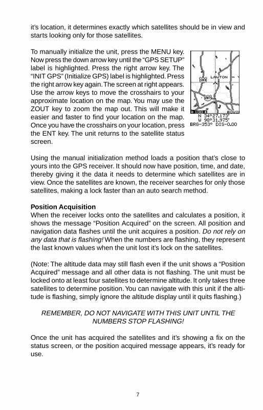
To manually initialize the unit, press the MENU key.Now press the down arrow key until the “GPS SETUP”label is highlighted. Press the right arrow key. The“INIT GPS” (Initialize GPS) label is highlighted. Pressthe right arrow key again. The screen at right appears.Use the arrow keys to move the crosshairs to yourapproximate location on the map. You may use theZOUT key to zoom the map out. This will make iteasier and faster to find your location on the map.Once you have the crosshairs on your location, pressthe ENT key. The unit returns to the satellite statusscreen.
Using the manual initialization method loads a position that’s close toyours into the GPS receiver. It should now have position, time, and date,thereby giving it the data it needs to determine which satellites are inview. Once the satellites are known, the receiver searches for only thosesatellites, making a lock faster than an auto search method.
Position AcquisitionWhen the receiver locks onto the satellites and calculates a position, itshows the message “Position Acquired” on the screen. All position andnavigation data flashes until the unit acquires a position. Do not rely onany data that is flashing! When the numbers are flashing, they representthe last known values when the unit lost it’s lock on the satellites.
(Note: The altitude data may still flash even if the unit shows a “PositionAcquired” message and all other data is not flashing. The unit must belocked onto at least four satellites to determine altitude. It only takes threesatellites to determine position. You can navigate with this unit if the alti-tude is flashing, simply ignore the altitude display until it quits flashing.)
REMEMBER, DO NOT NAVIGATE WITH THIS UNIT UNTIL THENUMBERS STOP FLASHING!
Once the unit has acquired the satellites and it’s showing a fix on thestatus screen, or the position acquired message appears, it’s ready foruse.

8
POSITION/NAVIGATION SCREENSThis unit has four modes: status, map, navigation, and window groups.Use the PAGES and arrow keys to switch between the different screens.The four screens that show by default are shown below.
STATUS NAVIGATION MAP WINDOWS
To change modes, simply press the PAGES key. Ascreen similar to the one at right appears. Use the upor down arrow keys to change modes. (The windowsmode is shown as “groups”. Group “A” is the first win-dows group.)
Press the right arrow key while the above menu is show-ing to switch between different versions of each mode.When the desired screen appears, press the EXIT keyto erase the menu.
Navigation ScreensThere are two different navigation screens. Nav screen number one showsa graphical view of your trip, Nav screen number 2 shows all navigationdetails in large digital numbers. You can also customize both navigationscreens to show data other than the default. See the “Programming Boxes”section for more information.
Nav Screen #1This screen has a compass rose that shows not onlyyour direction of travel, but also the direction to a re-called waypoint. The navigation screen looks like theone at right when you’re not navigating to a waypoint.Your position is shown by an arrow in the center of thescreen. Your trail history, or path you’ve taken is de-picted by the line extending from the arrow. The arrow

9
pointing down at the top of the compass rose indicates the current track(direction of travel) you are taking. This is also shown in the “TRK” (track)box at the top of the screen. On the example shown at right, the track is355°. The current ground speed (GS) shows in the box in the lower cen-ter of this screen.
When navigating to a waypoint, Nav screen numberone looks like the one at right. Bearing to the destina-tion waypoint is in the box in the upper left corner. Bear-ing is also shown by the large arrow pointing up to-wards the compass, above the present position arrow.Distance from the present position to the waypoint (DIS)shows beneath the compass on the lower left side ofthe screen.
Lines on either side of the present position show thecurrent cross track error range. Cross track error is the distance you areoff-course to the side of the desired course line. The course line is animaginary line drawn from your position when you started navigating tothe destination waypoint. It’s shown on the screen as a vertical dottedline. The default for the cross track error range is 0.25 mile. For example,if the present position symbol touches the right cross track error line, thenyou are .25 mile to the right of the desired course. You need to steer left toreturn to the desired course. The cross track error isalso shown in the “XTK” box. In the upper right corneris the course (CRS) box showing the direction fromyour starting position to the waypoint. Remember, acourse is a proposed path from the starting position tothe destination. Track is your actual direction of travel.
A circle depicting your destination (waypoint) appearson the screen as you approach the waypoint as shownon the screen at right.
Nav Screen #2This navigation screen shows all navigation informa-tion in large digital numbers. To view this screen, pressthe PAGES key, then press the up arrow key until the“NAV1” label is highlighted. While it’s highlighted, pressthe right arrow key. The screen shown at right appears.Press the EXIT key to erase the menu.
This screen is composed of eight digital boxes. Track(TRK) and ground speed (GS) data are all that show if

10
you’re not navigating to a waypoint. If you are navigat-ing to a waypoint, then bearing (BRG), distance towaypoint (DIS), estimated time en route (ETE), crosstrack error (XTK), destination arrow, and the CDI alsooperate. See below for more information on the CDI.
The destination arrow shows the direction to thedestination when the top of the screen is pointing inyour direction of travel.
Course Deviation Indicator (CDI)Once navigation to a waypoint is established, the CDIshows your distance to the left or right of the desiredcourse. The vertical line in the box shows both the di-rection you must steer to get back on course and thedistance to the course line. For example, if you’re trav-elling straight towards the destination, from the start, then the line stays inthe center. If you drift off course to the right, the line moves to the left. Thissignifies that you need to steer to the left to get back on course. This iscalled “chasing the needle”. If you steer towards the line (needle), you’llalways be heading in the correct direction to get back on course.
The CDI’s range shows beneath the CDI label. On the above screen, theCDI range is .20 mile, which is the default. You can adjust the range byselecting the “ALARMS/CDI” label on the main menu. This is also shownby the dotted lines at the far left and right side of the CDI. If the solid lineis on either of the dotted lines, then you are 0.20 mile off course. Remem-ber, if the line moves to the left, then you are too far to the right of thedesired course line and vice-versa.
Using the CDI with a mapping screen helps you visu-alize your position in relation to the course. The screenon the right shows that we are off course to the right.The vertical bar has moved to the left side of the CDI,showing the direction to the desired course line. TheCDI gives you a quick, easy to read visual indicator ofyour relationship between your direction of travel andthe desired direction.
11
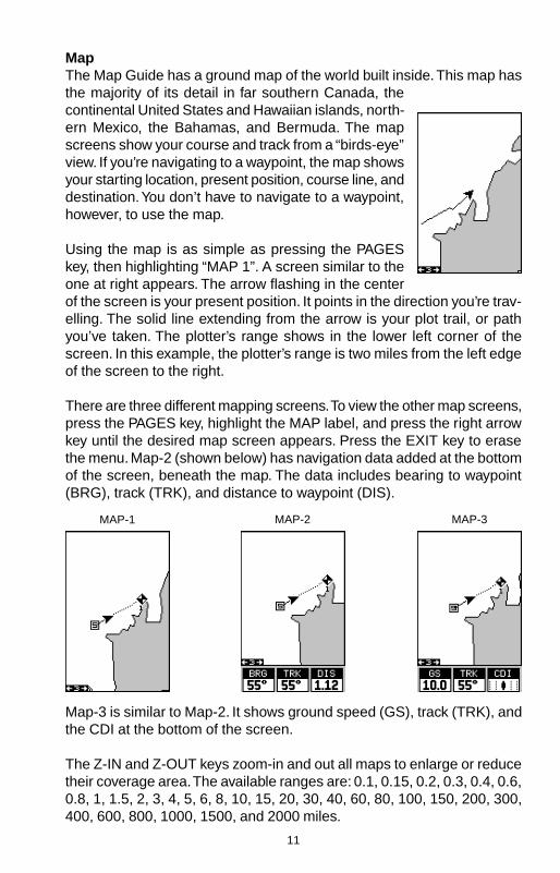
MapThe Map Guide has a ground map of the world built inside. This map hasthe majority of its detail in far southern Canada, thecontinental United States and Hawaiian islands, north-ern Mexico, the Bahamas, and Bermuda. The mapscreens show your course and track from a “birds-eye”view. If you’re navigating to a waypoint, the map showsyour starting location, present position, course line, anddestination. You don’t have to navigate to a waypoint,however, to use the map.
Using the map is as simple as pressing the PAGESkey, then highlighting “MAP 1”. A screen similar to theone at right appears. The arrow flashing in the centerof the screen is your present position. It points in the direction you’re trav-elling. The solid line extending from the arrow is your plot trail, or pathyou’ve taken. The plotter’s range shows in the lower left corner of thescreen. In this example, the plotter’s range is two miles from the left edgeof the screen to the right.
There are three different mapping screens. To view the other map screens,press the PAGES key, highlight the MAP label, and press the right arrowkey until the desired map screen appears. Press the EXIT key to erasethe menu. Map-2 (shown below) has navigation data added at the bottomof the screen, beneath the map. The data includes bearing to waypoint(BRG), track (TRK), and distance to waypoint (DIS).
MAP-1 MAP-2 MAP-3
Map-3 is similar to Map-2. It shows ground speed (GS), track (TRK), andthe CDI at the bottom of the screen.
The Z-IN and Z-OUT keys zoom-in and out all maps to enlarge or reducetheir coverage area. The available ranges are: 0.1, 0.15, 0.2, 0.3, 0.4, 0.6,0.8, 1, 1.5, 2, 3, 4, 5, 6, 8, 10, 15, 20, 30, 40, 60, 80, 100, 150, 200, 300,400, 600, 800, 1000, 1500, and 2000 miles.

12
CursorPressing an arrow key turns on two dotted lines thatintersect at the present position symbol. These linesare called a “cursor” and have a variety of uses.To turn the cursor on, simply press the arrow key in thedirection you want the cursor to move. This lets youview areas on the plotter that are away from yourpresent position. The zoom-in and zoom-out keys workfrom the cursor’s position when it’s active - not thepresent position. You can zoom in on any detail, any-where. The cursor can also place icons and waypoints.
Press the EXIT key to erase the cursor. The unit centers your presentposition on the screen after erasing the cursor.
Map SetupThe map has many customization options. To changethem, first press the MENU key while a map is showingon the screen. The map setup screen is highlighted.Press the right arrow key. A screen similar to the oneat right appears.
Change MapsChanges made to the map using the options in theMap Setup is normally made to all map screens. Thechange can be limited to the map screen currently in use, however, byswitching the “All Maps” to “This Map” in the “Change” menu. To do this,simply highlight the “Change” label, then press the right arrow key. Toswitch back, repeat the above.
Map OptionsThe following map options are listed under the “MapOptions” menu: Map Orientation, Auto Zoom, ViewDestination, Range Rings, and Grids.
Map OrientationBy default, this receiver shows the map with north al-ways at the top of the screen. This is the way mostmaps and charts are printed on paper. This is fine ifyou’re always travelling due north. What you see to yourleft corresponds to the left side of the map, to your right is shown on theright side of the map, and so on. However, if you travel any other direction,the map doesn’t line up with your view of the world.
13
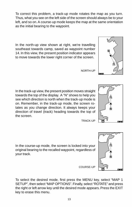
To correct this problem, a track-up mode rotates the map as you turn.Thus, what you see on the left side of the screen should always be to yourleft, and so on. A course-up mode keeps the map at the same orientationas the initial bearing to the waypoint.
In the north-up view shown at right, we're travellingsoutheast towards camp, saved as waypoint number14. In this view, the present position indicator appearsto move towards the lower right corner of the screen.
In the track-up view, the present position moves straighttowards the top of the display. A "N" shows to help yousee which direction is north when the track-up mode ison. Remember, in the track-up mode, the screen ro-tates as you change direction. It always keeps yourdirection of travel (track) heading towards the top ofthe screen.
In the course-up mode, the screen is locked into youroriginal bearing to the recalled waypoint, regardless ofyour track.
NORTH-UP
TRACK-UP
COURSE-UP
To select the desired mode, first press the MENU key, select “MAP 1SETUP”, then select “MAP OPTIONS”. Finally, select “ROTATE” and pressthe right or left arrow key until the desired mode appears. Press the EXITkey to erase this menu.

14
AUTOZOOMThis receiver has an autozoom feature that eliminates much of the buttonpushing that competitive units force you to make. It works in conjunctionwith the navigation features. First, recall a waypoint. (See the waypointsection for more information on navigating to a waypoint.) Then, with theautozoom mode on, the unit zooms out until the entire course shows,from the present position to the destination waypoint (recalled waypoint).As you travel towards the destination, the unit automatically begins zoom-ing in, one zoom range at a time, keeping the destination on the screen.
The screens below show a slice of the progression of a trip near a lake.Screen number one is the start and is on the 6 mile range. Intermediatestages progressively zoom in as it gets closer to the destination.
1 2 3
4 5 6

15
To use the autozoom feature, first press the MENU key, select “Map 1Setup”, then “Map Options”. Highlight “Auto Zoom”, then press the rightarrow key to turn it on. Press the EXIT key repeatedly to erase the menus.
VIEW DESTINATIONThe GPS receiver normally centers the present position on the screenand moves the map past it. If a waypoint is recalled, the unit can centerthe waypoint on the screen, instead of the present position. To do this,press the MENU key, select “Map 1 Setup”, then “Map Options”. Highlight“View Dest”, then press the right arrow key to turn it on. Press the EXITkey repeatedly to erase the menus.
VIEW DESTINATIONOFF
VIEW DESTINATIONON
Range Rings/Grid LinesThe map screen can be customized with rings that are 1/4 of the rangeand/or grids that divide the plotter into equal segments of latitude andlongitude. To do this, press the MENU key, select “Map 1 Setup”, then“Map Options”. Highlight the desired option, then press the right arrowkey to turn it on. Press the EXIT key repeatedly to erase the menus. Asample screen of each type shows below.
RANGE RINGS GRID BOTH RINGS & GRID

16
EARTH MAP OPTIONSThe earth map consists of the built-in background mapof the world. To change the Earth map options, firstpress the MENU key, then select the Earth Map label.Press the right arrow key. The screen shown at rightappears.
Earth Map On/OffThe background map can be turned on or off using the“Earth Map” menu. The earth map is the backgroundmap that shows on the map screens. Simply highlightthe menu, then press the left arrow key to turn it off.
Text LabelsSelect “Map Text” to turn all names on the map (such as Lake Tahoe orMississippi River) off or on. The default is “on”. Press the left arrow key toturn them off.
LocationsNormally, text disappears as you zoom out. Thisdeclutters the screen, making it easier to see signifi-cant map detail. Turning “Locations” on from the earthmap menu places a dot on the screen where a textlabel should be when the screen is zoomed out. Thearrows on the screen at right show two locations where,if zoomed in, text will show.
Map DetailThe detail shown on the background map diminishes as the screen iszoomed out. This prevents cluttering of the display, or overlapping of textand graphics which can make it unreadable. There are two detail levels:
EARTH MAP ON EARTH MAP OFF

17
NORMAL DETAIL HIGH DETAIL
normal and high. The difference between the two shows below. The screenon the left is normal detail, on the right is high detail. Both screens are onthe 40 mile range. Normally, you’ll only see a difference in detail when theunit is zoomed out to the 30 mile range or higher.
To change the map’s detail setting, select “Map Detail” from the earthmap menu, then press the right arrow key.
Gray FillWhen this unit is first turned on, all water (lakes, oceans, rivers) is filledwith gray to distinguish it from land, which is clear. (See below) To makethe land fill with gray and water remain clear, select the “Gray Fill” labelfrom the Earth Map menu, then press the left arrow key. Press the EXITkey repeatedly to return to the mapping screen.
WATER FILLEDWITH GRAY
LAND FILLED WITHGRAY
Normally, you'll want to fill water with gray when you're using the GPSreceiver on land and fill land with gray when you're using it on the water.

18
TRAIL OPTIONSThe line extending from the present position symbol iscalled a plot trail. You can customize the plot trail andsave trails using the trail options menu. To use it, pressthe MENU key, select “MAP SETUP”, then “TRAILOPTIONS”. The screen at right appears.
Clear TrailTo erase the current plot trail from the screen, selectClear Trail from the Trail Options menu. A message ap-pears, asking if you really want to erase the plot trail.Follow the instructions on the screen. When the trail is erased, the unitreturns to the map screen.
Flash TrailBy default, the plot trail flashes once per second. This typically makes iteasier to see the plot trail against the background map. To turn the flash-ing off, select “FLASH TRL” from the trail options menu. Press the leftarrow key to turn it off.
Update OptionsBy default, the plotter places a dot on the screen every3 seconds to create the plot trail. You can change thistime from once per second to once every thirty min-utes. The plot trail can also be updated by distanceinstead of by time. The distance update rate can be setfrom 0.01 to once every 10 miles.
From the trail options menu, choose “UPDATE BY” tochange the update rate or type. To change the rate ordistance, simply select either the “UPDATE RATE” or‘UPDATE DIS” menus as appropriate, use the left or right arrow keys toadjust it, then press the EXIT key to erase the menu.
PLOT TRAILS - Save TrailThis unit automatically saves the current plot trail inmemory when you turn it off. You can save two othertrails in memory. To save your current plot trail in a spe-cific memory location, choose “SAVE TRAIL” from the“TRAIL OPTIONS” menu. The screen shown at rightappears. Highlight the desired number that you wish tosave the current trail under, (i.e. “Trail 1 or Trail 2) andpress the right arrow key. Your current trail is saved.Press the EXIT key to erase this menu.

19
PLOT TRAILS - Trails ShownThe current plot trail shows on the plotter by default. Toplace a previously saved trail onto the plotter, choose“TRAILS SHOWN” from the Trail Options menu. Thescreen shown at right appears. Highlight the desiredtrail on this screen, then press the right arrow key toselect it. Press the EXIT key to erase this menu. Theselected plot trail shows on the plotter.
ICONSThe plotter has 28 symbols or “icons” available that can be placed any-where on the screen. They can be used to mark fishing or hunting loca-tions, landmarks, boat ramps, and virtually any point of interest. An iconcan be placed at your present position or at the cursor’s location.
Place Icon - Present PositionTo place an icon at your present position, simply pressthe ENT key while the mapping screen is on. The screenshown at right appears. Use the arrow keys to high-light the desired icon. Now press the ENT key again.The mapping screen reappears with the icon showingat the position you were at when the ENT key waspressed.
MAP-1 SCREENPRESS ENT KEY
SELECT ICONPRESS ENT KEY
ICON PLACEDAT POSITION.

20
Icon OptionsIcons can be erased from the plotter individually, all ofa specific type, or all at once. They can also simply beturned off without erasing them. To make changes tothe icons, press the MENU key, then select MAPSETUP, and finally select Icon Options. The screenshown at right appears.
The first menu (ICONS OFF/ON) simply turns all iconsymbols off or on. This doesn’t erase the icons, it sim-ply “hides” the icons from the map. You can use thisfeature to temporarily de-clutter the display.
The DEL ALL ICONS selection does erase all of the icons from memory,Use this only if you want to erase all icons that have been placed on allmap screens.
To erase only a certain type of icon, select the DEL ICON TYPE menu.The icon menu appears. Highlight the icon style that you want to erasefrom memory, then press the ENT key. The unit returns to the map screenwith only the selected icons erased.
MOVE CURSORPRESS ENT KEY
SELECT ICONPRESS ENT KEY
ICON PLACED ATCURSOR POS.
Place Icon - Cursor PositionTo place an icon at the cursor’s position, first use the arrow keys to movethe cursor to the location that you wish to place the icon. Next, press theENT key. Now select the icon using the arrow keys. While it’s selected,press the ENT key. The map reappears with the icon placed at the cursorcrosshairs. Press the EXIT key to erase the cursor. On the screens shownbelow, the tent icon was placed at the cursor’s location.

21
You can delete individual icons by selecting the DELFROM MAP menu from the Icon Options menu. Oncethis menu is selected, the unit returns to the plotterscreen with the cursor activated as shown at right. Usethe arrow keys to move the cursor to the icon that youwant to erase. Once the crosshairs are on top of theicon, press the ENT key. The icon is immediately erased.Press the EXIT key to erase the cursor.
WINDOWSThe windows feature provides ten different data screenschosen for their broad range of navigation informationand ease of use.
To use the windows feature, press the PAGES key, thenhighlight the “GROUP A” label at the bottom of thescreen. Group A is visible in the background when youswitch to the windows group. Press the left or right ar-row key to switch between all off the groups. When thedesired group appears, press the EXIT key to erasethe Pages menu. A summary of the groups follows. Notethat many of the groups have navigation data that re-quire navigation to a waypoint in order to show data.See the waypoint section for information on setting up the unit for way-point navigation.
Group AThis screen has two maps, one above the other. Each map works sepa-rately from the other. For example, the top map has autozoom turned on,while the bottom map doesn’t. To zoom in or out on the bottom map,simply press the ZIN or ZOUT keys. The main menu also has selectionsfor the upper map and lower map setups.
GROUP A MAIN MENU

22
Group BThis screen has a map in the track-up mode on the tophalf with bearing (BRG), distance to go (DIS), track(TRK) and the CDI on the lower half. (See page 10 foran explanation of the CDI.)
Group CA half screen map in the track-up mode again appearsat the top. The CDI shows in the middle of the screen.Your present course (CRS) shows at the top of the CDI.Track (TRK) and distance to go (DIS) show at the bot-tom of the screen.
Group DThis screen is the same as group C except groundspeed (GS) replaces distance to go (DIS) in thelower right corner.
Group EA CDI combined with digital boxes makes up thisscreen. Beneath the CDI are bearing (BRG), distanceto go (DIS), track (TRK), ground speed (GS), and alti-tude (ALT).
23
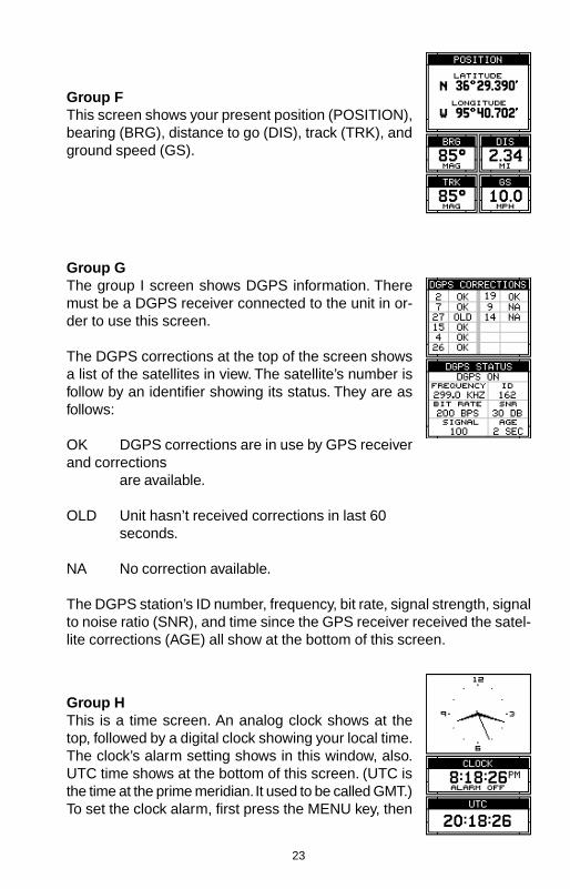
Group FThis screen shows your present position (POSITION),bearing (BRG), distance to go (DIS), track (TRK), andground speed (GS).
Group GThe group I screen shows DGPS information. Theremust be a DGPS receiver connected to the unit in or-der to use this screen.
The DGPS corrections at the top of the screen showsa list of the satellites in view. The satellite’s number isfollow by an identifier showing its status. They are asfollows:
OK DGPS corrections are in use by GPS receiverand corrections
are available.
OLD Unit hasn’t received corrections in last 60seconds.
NA No correction available.
The DGPS station’s ID number, frequency, bit rate, signal strength, signalto noise ratio (SNR), and time since the GPS receiver received the satel-lite corrections (AGE) all show at the bottom of this screen.
Group HThis is a time screen. An analog clock shows at thetop, followed by a digital clock showing your local time.The clock’s alarm setting shows in this window, also.UTC time shows at the bottom of this screen. (UTC isthe time at the prime meridian. It used to be called GMT.)To set the clock alarm, first press the MENU key, then

24
TRIP TIMER MENU
select “CLOCK ALM SETUP” and press the right arrow key. The screenshown below left appears. Now press the right arrow key. The screenbelow center appears. Using the arrow keys, enter the alarm’s time. Press
the ENT key. The unit returns to the clock alarm menu. Highlight the“CLOCK ALM OFF ON” menu and press the right arrow key to turn it on.Press the EXIT key to erase the menus. The unit returns to the group withthe alarm’s time showing in the clock’s window.
CLOCK ALARMMENU
CLOCK ALARMADJUST MENU
CLOCK ALARMSET
Group IThis group has estimated time enroute (ETE) at thetop of the screen, a trip timer, estimated time of arrival(ETA), and the digital clock.
The trip timer measures the total time you have beentravelling. It starts counting when you exceed a presetspeed. The default is 5 miles per hour. You can adjustthis time from zero to 200 m.p.h.. To do this, press theMENU key, then select “TRIP TIMER SETUP” menu.The screen at right appears. Highlight the “START GS”label, then press the left or right arrow keys until thedesired speed appears. Press the EXIT key to erasethis screen.

25
Group JThere are three timers on this screen and an odometer(TRIP METER). The trip timer is described in group I.The trip meter measures the distance you’ve travelledsince it was last reset. To reset the trip meter, press theMENU key, then select “TRIP METER RESET” andpress the right arrow key. The unit returns to Group Jwith the trip meter reset to zero.
The up timer starts at zero and counts up. The up timeralso has an alarm. The down timer starts from a user setting and countsdown to zero.
To start a timer, first press the MENU key, then highlight the desired timersetup menu. In this example, we’re using the count up timer, so the UPTIMER SETUP was selected. Now press the right arrow key. A screensimilar to the one above center appears. To start the timer, simply high-light the “UP TIMER” menu, then press the right arrow key. To reset thetimer to zero, select the “UP TIMER RESET” menu. The up timer has analarm that can be set to sound at a preset time. (For example, one hourfrom now, three hours, etc.) To set the alarm, highlight the “UP TIMERALM SET” and press the right arrow key. The screen at the upper rightappears.
Using the arrow keys, highlight the first number in the time that you wantto set. (The time is in hours, minutes, and seconds) Now press the up ordown arrow keys until the desired number shows. Continue until the timeshown in the display is correct, then press the ENT key. The unit returnsto the timer menu screen. To turn the alarm on, highlight the “UP ALARM”label. Press the right arrow key. Press the EXIT key to erase the menu.The time you set shows in the “UP TIMER” box . The timer continues
MAIN MENU UP TIMER MENU UP TIMER SET

26
counting until you stop it. When it reaches the alarm’s time setting, a tonesounds. Press the EXIT key to shut the alarm off.
The countdown timer starts from a time that you enter and counts downto zero. (Note: When the countdown timer reaches zero, it begins count-ing up until you press the EXIT key. This tells you how long it’s been sincethe alarm sounded.) Use the “DOWN TIMER SETUP” menu to adjust thecountdown timer and reset it to zero.
Reprogram BoxesThe digital boxes on MAP 2 and 3 and both NAV screenscan be reprogrammed, changing the informationsshown by the boxes.
To customize a screen, first switch to the screen thatyou want to customize. Map-2 (shown at right) is usedin this example. Next, press the MENU key, then selectthe “Reprogram Boxes” menu. The screen shown be-low left appears.
This is the MAP-2 edit screen. The “BRG” box near the left corner flashes,which means it’s ready for change. If you don’t want to change this box,simply press the left or right arrow key to move to the box that you do wantto change. In this example, we will change the bearing (BRG) box to
ground speed (GS). To do this, simply press the up or down arrow keywhile the box is flashing. The box changes each time the arrow key ispressed. When the desired box appears, then you can change anotherbox or save your changes by pressing the ENT key. If you want to leavethis screen without saving the changes, simply press the EXIT key. In this

27
example, we simply changed the BRG to GS, then pressed the ENT key.The screen on the far right on the previous page is the final version. Usethis same method to change the NAV screens.
RESET GROUPSTo restore all boxes on the navigation and plotter screens to their factorysettings, first press the MENU key, then highlight the “System Setup” la-bel and press the right arrow key. Now highlight the “Reset Groups” labelon this menu. Press the right arrow key. A message appears, asking if youreally want to do this. Press the right arrow key to continue, or the leftarrow key to exit without resetting the groups.
WAYPOINTSThis GPS receiver gives you the ability to create your own database oflocations, called “waypoints’. You can save your present position, cursorposition, or enter a coordinate and save it as a waypoint. For example,you may wish to store the location of your parked car as a waypoint be-fore starting on a hike. When you want to return to the car, all you have todo is recall the waypoint and the unit will show distance and bearing fromyour present position to the car. This unit stores up to 750 waypoints.
Waypoint MenuWith few exceptions, in order to save, modify, or recalla waypoint, you’ll use the waypoint menu, shown atright. The current waypoint number shows at the top ofthe screen. Its name appears beneath the “GO TOWPT” label. The waypoint’s position, distance and bear-ing from your present position to the waypoint, and thedate and time the waypoint was saved show at thebottom of the screen. It’s icon shows just to the right ofthe distance and bearing. In short, all of the detail aboutthe waypoint shows on this screen.
Saving Your Present Position as a Waypoint(Quick Save Method)To save your present position, simply press the WPTkey twice. Your current position is placed into the firstavailable waypoint number on the list. A message ap-pears on the display telling you the waypoint number itjust used. This also momentarily places you in the way-point menu. Anytime this menu is showing, simply pressthe WPT key once and the unit will store your presentposition on the waypoint list. In this case, waypointnumber two was assigned when the position was saved.

28
Saving The Cursor Position as a WaypointWhen the cursor is showing on the map and you press the WPT keytwice, the cursor’s position is placed into the first available waypoint num-ber. In the example screen shown below, the cursor is placed at thedesired location. Pressing the WPT twice causes waypoint number threeto be placed at the cursor’s crosshairs. (Waypoint 3 was the next availablewaypoint number.) A message appears on the display telling you thewaypoint number it just used. Wait a few seconds and the menu will clearautomatically. Press the EXIT key to erase the cursor.
Saving Your Present Position as a Waypoint(Select Number Method)The method shown previously doesn’t let you choosethe waypoint number. You can pick the waypoint num-ber, then save your present or cursor position. To saveyour present position, press the WPT key once. (Ifyou’re saving the cursor position, first move the cursorto the desired location, then press the WPT key.) Ascreen similar to the one at right appears.
Highlight the “WPT” label at the top of the screen. Pressthe right or left arrow keys until the desired waypointnumber appears that you wish to save your present(or cursor) location under. Waypoint number 4 is usedin this example. Now select “CREATE WPT” . A screensimilar to the one at right appears. Finally, highlight“CURRENT POS” and press the right arrow key. Theunit returns to the waypoint screen with the positionsaved under the selected waypoint number. Note: youcan save the position on any waypoint number, even ifa position is already stored on the desired number.
MOVE CURSOR TODESIRED LOCATION
PRESS WPT KEYTWICE
29
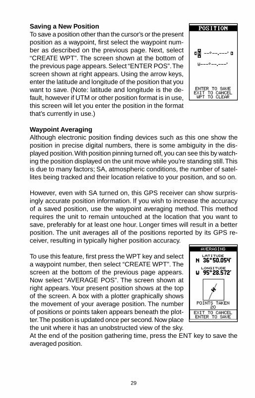
Saving a New PositionTo save a position other than the cursor’s or the presentposition as a waypoint, first select the waypoint num-ber as described on the previous page. Next, select“CREATE WPT”. The screen shown at the bottom ofthe previous page appears. Select “ENTER POS”. Thescreen shown at right appears. Using the arrow keys,enter the latitude and longitude of the position that youwant to save. (Note: latitude and longitude is the de-fault, however if UTM or other position format is in use,this screen will let you enter the position in the formatthat’s currently in use.)
Waypoint AveragingAlthough electronic position finding devices such as this one show theposition in precise digital numbers, there is some ambiguity in the dis-played position. With position pinning turned off, you can see this by watch-ing the position displayed on the unit move while you’re standing still. Thisis due to many factors; SA, atmospheric conditions, the number of satel-lites being tracked and their location relative to your position, and so on.
However, even with SA turned on, this GPS receiver can show surpris-ingly accurate position information. If you wish to increase the accuracyof a saved position, use the waypoint averaging method. This methodrequires the unit to remain untouched at the location that you want tosave, preferably for at least one hour. Longer times will result in a betterposition. The unit averages all of the positions reported by its GPS re-ceiver, resulting in typically higher position accuracy.
To use this feature, first press the WPT key and selecta waypoint number, then select “CREATE WPT”. Thescreen at the bottom of the previous page appears.Now select “AVERAGE POS”. The screen shown atright appears. Your present position shows at the topof the screen. A box with a plotter graphically showsthe movement of your average position. The numberof positions or points taken appears beneath the plot-ter. The position is updated once per second. Now placethe unit where it has an unobstructed view of the sky.At the end of the position gathering time, press the ENT key to save theaveraged position.

30
Project a WaypointYou can save a waypoint even if you don’t know it’sposition or location on the map. This unit lets you projectthe location of a waypoint from a known waypoint us-ing only bearing and distance from the known way-point. This is useful if you don’t know the latitude/longi-tude of a location, but you do know the distance andbearing from a saved waypoint or your own position.
(Note: To project a waypoint from your present posi-tion, you must first save your present position as awaypoint.)
To use this feature, press the WPT key, then select awaypoint number that you want to save the projectedwaypoint under. Waypoint 5 is used in this example.Now select “CREATE WPT”. Finally, select “PROJECTPOS”. The screen shown above appears.
The unit needs a location (reference waypoint) toproject the new waypoint from. The default referenceis waypoint number one. Highlight the “REFERENCEWPT” label on the Project WPT menu and press theright arrow key. The screen at right appears. Select awaypoint using either the waypoint number, or way-point list. When you’ve chosen the waypoint, highlightthe “SET REFERENCE” label and press the right ar-row key. The unit returns to the Project WPT screenshown above. The starting waypoint you chose showsin the middle of this screen. Now set the distance fromthe starting waypoint to the projected waypoint by high-lighting the “SET DIST” label and pressing the rightarrow key. Use the arrow keys to set the distance, thenpress the ENT key when you’re finished. The unit re-turns to the Project WPT screen. Now enter the bear-ing from the starting waypoint to the projected way-point by selecting “SET BRG” from the Project WPTscreen. Once you’ve entered the bearing, the unit re-turns to the Project WPT screen with the distance andbearing showing at the bottom of the screen, as shownat right. In this example, a distance of 2.5 miles and abearing of 50° was used. Now press the ENT key. Theunit saves the projected location under the waypointnumber that you picked at the beginning.

31
SELECTING A WAYPOINTIn order to edit or navigate to a waypoint, you must firstselect it. There are three ways to do this: by waypointnumber, waypoint list, or search by name. All selectionmethods are on the main waypoint menu shown at right.
Waypoint NumberTo select a waypoint by its number, simply highlightthe “WPT” label at the top of the waypoint menu, thenpress the left or right arrow keys until the desired way-point number appears.
Waypoint ListThe waypoint number selection method forces you toscroll through all waypoint numbers, whether there’s alocation saved in them or not. The waypoint list is com-posed only of saved waypoints. To use the list, select“WPT LIST” from the waypoint menu. The screen shownat right appears. The names of all waypoints stored inmemory show on this list. Simply highlight the desiredwaypoint and press the right arrow key to select it. Thewaypoint menu reappears.
(Note: When created, a waypoint is given a default name designated byan asterisk (*). Default names are not shown on the map. The waypointnumber is shown until it’s renamed.)
EDITING A WAYPOINTYou can customize a waypoint by giving it a name or change it’s positionor icon. To do this, first press the WPT key. The waypoint screen appears.Follow the instructions below for each item.
Edit PositionAny latitude/longitude can be assigned to any waypointby manually entering it using the keyboard. First se-lect the waypoint number that you want to save a po-sition under from the waypoint menu. Next, highlight“EDIT POSITION” and press the right arrow key. Thescreen shown at right appears. Using the left and rightarrow keys, highlight each number in the position andchange it using the up and down arrow keys. Whenyou’re ready to save this position and return to the way-point screen, press the ENT key. Note: You can alsouse this method to change the position of an existing waypoint.

32
Edit NameYou can assign a name to each waypoint. The namecan have up to eight characters. To do this, first selectthe waypoint that you wish to name, then choose “EDITNAME” from the waypoint menu. A screen similar tothe one at right appears.
Press the up or down arrow keys to select the firstletter in the name. Press the right arrow key to high-light the next position in the name. Repeat this se-quence until you’ve entered all of the letters in the way-point name. Press the ENT key to accept this name, the WPT key toerase all characters in the name, or the EXIT key to leave this screenwithout saving any changes.
Edit IconTo change the icon assigned to a waypoint, first selectthe waypoint, then choose “EDIT SYMBOL”. The screenat right appears. Use the arrow keys to select the iconthat you want to assign to the waypoint, then press theENT key. The waypoint now has the new icon.
WAYPOINT NAVIGATIONThe Map Guide makes it easy to navigate to any waypoint. All you have todo is select the waypoint (see page 31), then highlight the “GO TO WPT”label on the waypoint screen and press the right arrow key. The unit im-mediately shows navigation information to the waypoint on all navigation,map, and windows screens.
In this example, waypoint number 4 was recalled.Switching to the MAP-2 screen (at right) shows thestarting location “S”, the recalled waypoint “4”, the plottrail from the starting location to the present position,and the present position. The present position arrowalso shows the direction of travel (track).
Navigating to a cursor locationThis unit lets you navigate to a location without storingit in the waypoint database by using the map and cursor. To do this, firstswitch to a map. Now move the cursor to the location that you want tonavigate to. Next, press the MENU key. A new, highlighted menu appears

33
on the list: “Go To Cursor”. Press the right arrow key. It now shows naviga-tion data to the cursor location (shown as “D” on the map). See the screensbelow.
Navigating to a Waypoint using the MapThe unique “birds-eye” view used by the map givesyou an easy way to navigate to a waypoint. On the mapscreen shown at right, the arrow is your present posi-tion. The box with the “S” in it was your starting locationwhen the waypoint was recalled. The dotted line is calleda course line and is the shortest path from the startinglocation to the destination. The number “4” is waypointnumber four, which is the recalled waypoint and thedestination. The “D” on the map screen at the top ofthis page is the cursor destination, when the cursorposition is used as a destination. If you follow the courseline, you’ll reach the destination, covering the shortest distance in theleast time.
CAUTION!This product does NOT take land features, restricted or prohibited areas,or any other feature into account when it projects the course line on thescreen. Use caution when navigating to a location. Make certain there areno obstructions in your path.
OTHER WAYPOINT OPTIONSMove a WaypointYou can move all information from one waypoint number to another tohelp organize the waypoints. In this example, we’ll move all of the infor-mation in waypoint number 1 to waypoint number 10. To do this, highlightthe “MOVE WPT” on the waypoint screen and press the right arrow key.
MOVE CURSOR TODESIRED LOCATION
PRESS MENU KEY,THEN PRESS RIGHT
ARROW KEY
NAVIGATING TOCURSORPOSITION

34
The screen shown at right appears. The “From” label ishighlighted at the top of the screen. Press the right ar-row key until the waypoint number that you want to moveappears. In this example, we selected waypoint num-ber 1. Now press the down arrow key once to highlightthe “To” label. Press the left or right arrow key until thenumber that you want to move the waypoint to appears.Again, in this example, we chose to move waypointnumber 1 to waypoint number 10, so we pressed theright arrow key until “10” appeared. As you can see onthe screen above, waypoint number 1 is showing in the“From” box. Now press the ENT key. The “From” box isnow empty and the “To” box has waypoint number 10.
Note: The names in the “From” and “To” boxes are notthe waypoint numbers - they are the waypoint names.
Press the EXIT key to erase this menu.
Delete a WaypointTo erase all of the information in a waypoint, first pressthe WPT key, then select the waypoint you want to erase. Now highlightthe “DELETE WPT” label and press the right arrow key. A message ap-pears, asking if you really want to delete this waypoint. Press the rightarrow key to delete it, the left to exit without deleting the waypoint.
Delete All WaypointsYou can remove all of the waypoints from the unit’s memory. To do this,press the MENU key, then highlight the System Setup menu and pressthe right arrow key. Now highlight the DEL ALL WPTS label. The unit re-moves all waypoints from memory. Note: This also removes all routesfrom memory.
Waypoint OptionsYou can customize the method used to show a way-point on the map screens. To do this, first press theMENU key, then select “MAP SETUP”, finally select“WAYPOINT OPTIONS”. The screen shown at rightappears. You can turn all of the waypoints, their sym-bols, names, or numbers on or off. Simply select thedesired label, then press the appropriate arrow key.Press the EXIT key to erase this menu.

35
ROUTESYou can connect several user waypoints together to form a route. Whenyou recall the route, the unit shows navigation information to the first way-point in the route, then when you reach that waypoint, it switches to thenext waypoint, and so on until you reach the last waypoint in the route.
Create a RouteTo create a route, first press the MENU key, highlightthe “ROUTE PLANNING” label, and press the rightarrow key. The screen shown at right appears.
This unit can store up to 99 routes. Route number oneshows on this page. If you wish to create a route usinga different number, simply press the left or right arrowkeys until the desired route number appears. In thisexample, however, we’ll use route number one.
If you wish to name the route, highlight the “EDIT NAME” label and pressthe right arrow key. Use the arrow keys to name the route, (you can useup to eight characters in the name) then press the ENT key when you’refinished.
The gray boxes in the lower half of the screen com-prise the list of waypoints that form the route. To addwaypoints to the route, highlight the first gray box in themiddle of the screen and press the right arrow key. Thescreen shown at right appears. To add a waypoint tothe route from the waypoint table, select the “ADD WPT”label. The screen shown at the top left on the next pageappears.
Add From Waypoint ListThis screen is virtually identical to the waypoint screen Select a waypointeither by using the waypoint number, waypoint name, or from the way-point list. After selecting the waypoint, highlight the “ADD TO ROUTE”label and press the right arrow key. The unit returns to the route screenwith the first waypoint at the top of the list. Highlight the next waypointlocation beneath the first waypoint and press the right arrow key. Nowrepeat the previous steps to select the second waypoint for your route.After selecting the second waypoint, the unit returns to the waypoint listscreen. The second waypoint shows beneath the first one, with bearingand distance from the first waypoint in the route to the second showingunder the second waypoint’s name.
36
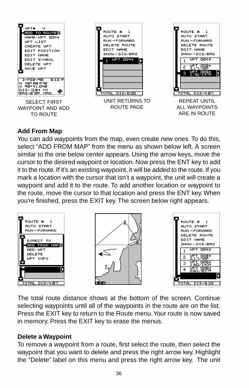
Add From MapYou can add waypoints from the map, even create new ones. To do this,select “ADD FROM MAP” from the menu as shown below left. A screensimilar to the one below center appears. Using the arrow keys, move thecursor to the desired waypoint or location. Now press the ENT key to addit to the route. If it’s an existing waypoint, it will be added to the route. If youmark a location with the cursor that isn’t a waypoint, the unit will create awaypoint and add it to the route. To add another location or waypoint tothe route, move the cursor to that location and press the ENT key. Whenyou’re finished, press the EXIT key. The screen below right appears.
SELECT FIRSTWAYPOINT AND ADD
TO ROUTE
UNIT RETURNS TOROUTE PAGE
REPEAT UNTILALL WAYPOINTSARE IN ROUTE
The total route distance shows at the bottom of the screen. Continueselecting waypoints until all of the waypoints in the route are on the list.Press the EXIT key to return to the Route menu. Your route is now savedin memory. Press the EXIT key to erase the menus.
Delete a WaypointTo remove a waypoint from a route, first select the route, then select thewaypoint that you want to delete and press the right arrow key. Highlightthe “Delete” label on this menu and press the right arrow key. The unit
37
returns to the route list with the waypoint removed fromthe list. (Note: This doesn’t delete the waypoint fromthe database, it simply removes it from the route.)
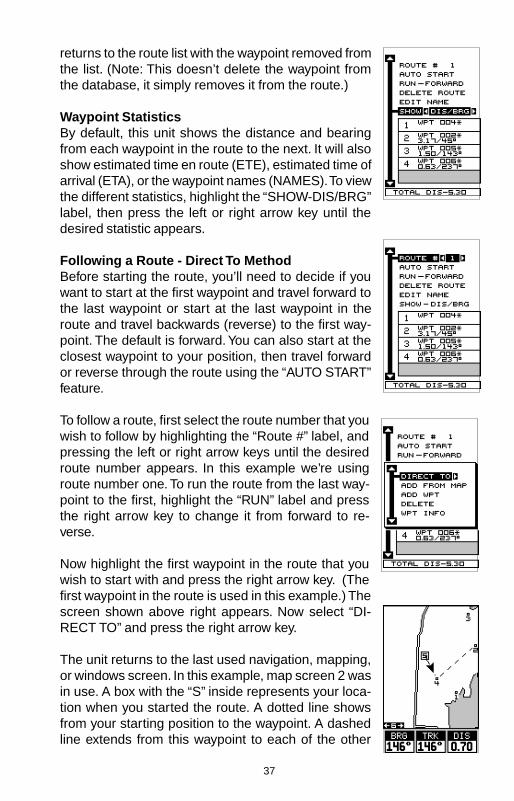
Waypoint StatisticsBy default, this unit shows the distance and bearingfrom each waypoint in the route to the next. It will alsoshow estimated time en route (ETE), estimated time ofarrival (ETA), or the waypoint names (NAMES). To viewthe different statistics, highlight the “SHOW-DIS/BRG”label, then press the left or right arrow key until thedesired statistic appears.
Following a Route - Direct To MethodBefore starting the route, you’ll need to decide if youwant to start at the first waypoint and travel forward tothe last waypoint or start at the last waypoint in theroute and travel backwards (reverse) to the first way-point. The default is forward. You can also start at theclosest waypoint to your position, then travel forwardor reverse through the route using the “AUTO START”feature.
To follow a route, first select the route number that youwish to follow by highlighting the “Route #” label, andpressing the left or right arrow keys until the desiredroute number appears. In this example we’re usingroute number one. To run the route from the last way-point to the first, highlight the “RUN” label and pressthe right arrow key to change it from forward to re-verse.
Now highlight the first waypoint in the route that youwish to start with and press the right arrow key. (Thefirst waypoint in the route is used in this example.) Thescreen shown above right appears. Now select “DI-RECT TO” and press the right arrow key.
The unit returns to the last used navigation, mapping,or windows screen. In this example, map screen 2 wasin use. A box with the “S” inside represents your loca-tion when you started the route. A dotted line showsfrom your starting position to the waypoint. A dashedline extends from this waypoint to each of the other

38
waypoints in the route. Follow these lines to get to each of the waypoints.When you enter the radius set by the arrival alarm, the unit automaticallyswitches to the next waypoint on the list, showing navigation data to thatwaypoint, and so on until the last waypoint on the route list has beenreached. (Note: The arrival alarm does not have to be turned on.) Theunit continues to show navigation data to the last waypoint in the routeuntil you end the navigation. (See “Cancel Navigation)
Following a Route - Auto Start MethodYou don’t have to choose the starting waypoint in aroute. Selecting “AUTO START” on the route planningmenu, starts navigation along the leg of the route thatis closest to your present position. The screen shownbelow left shows the result of the auto start feature.When the route was started, the first leg of the route(from waypoint #4 to waypoint #2) was the closest to
the present position. Therefore, the unit shows navigation information towaypoint number 2. The first leg of the route, from #4 to #2 is shown onthe screen by a dotted line. Once you arrive at waypoint number 2, theunit switches to the next waypoint in the route, and soon. The rest of the route navigation is used normally.
Waypoint InformationTo see details about the highlighted waypoint, selectthe waypoint from the list of waypoints on the routescreen, then press the right arrow key. The screen atright appears. Now select “WPT INFO”. The screen atthe top of the next page appears.

39
The selected waypoint number appears at the top ofthis screen. Information about the waypoint shows atthe bottom of the screen. When you’re finished withthis screen, press the EXIT key to erase it.
Delete a RouteTo erase a route, highlight the “ROUTE #” label on theroute planning menu, then select the route you want toerase. Next, highlight the “DELETE ROUTE” label andpress the right arrow key. A message appears, askingif you really want to erase the route. If you press theright arrow key, the route will be erased. If you select“Yes” (by pressing the right arrow key) the unit thenasks if you want to erase the waypoints used in theroute from memory also. Press the right arrow key againto erase them, or the left arrow key to leave the way-points in memory. The unit returns to the routes menu.Press the EXIT key to erase the menu.
CANCEL NAVIGATIONThis unit continues to navigate to a recalled waypoint,the last waypoint in a route, or the cursor position untilyou stop it.
To stop the navigation function, press the MENU key,then press the up or down arrow keys until the “CancelNav” label is highlighted. Press the right arrow key. Theunit stops showing navigation information.
Navigation NotesIf you are navigating with this unit, either to a waypoint or in a route andshut it off, it will preserve the current waypoint number that it is navigatingto. It also saves the current route (if it is in use) and the route’s forward orreverse order. When you turn the unit on, it will show navigation data tothe waypoint as soon as it locks onto the satellites as if it had never beenturned off.

40
SYSTEM SETUPMany features are listed under the “System Setup” la-bel on the main menu. These commands affect the ba-sic operation of the unit. To use them, press the MENUkey, then “System Setup”. The screen at right appears.
SoundTo turn the speaker off, highlight the “SOUND” label asshown below, then press the left arrow key. Note: Thisturns the speaker completely off. The unit will not sounda tone when a key is pressed, nor will any alarm sound.The alarm messages will still flash on the screen, how-ever.
ContrastTo adjust the display’s contrast, highlight the “Contrast”label. Press the right or left arrow keys until the screen’scontrast is best for the lighting conditions.
BacklightThe display has lights that can be turned on for nightuse. To turn the lights on, simply press the PWR key.To turn them off, press the PWR key again. A light bulb indicator on thesatellite status screen shows when the lights are on.
The default light level is maximum. To reduce the level, select “BACK-LIGHT”, then press the left arrow key until the lights are at the desiredlevel. To increase the light level, press the right arrow key.
The lights automatically turn off after 30 seconds topreserve the battery power. It will do this even if theexternal power is applied to the unit. The time delay isadjustable from 5 to 240 seconds by selecting LightDly from the System Setup menu . You can also turnthe lights on continuously from this menu. Highlight thismenu, then press the right arrow key to increase thetime the lights are on, the left arrow key to decrease it.
Set Local TimeWhen this unit is first initialized, it may not show thecorrect time for your location due to daylight savings time, time zone vari-ances, and so on. If the time shown on the clock displays is incorrect,select “SET LOCAL TIME” from the system setup menu and press theright arrow key. The screen shown at the top of the next page appears.

41
Use the left or right arrow keys to select the number inthe current time that you want to change. Use the up ordown arrow keys to change the number. Press the ENTkey to save the change, the EXIT key to erase the menuwithout changing it.
Units of MeasureYou can view data in three different formats: statute, nautical, and metric.The default is statute. The chart below shows the settings for each.
Statute Nautical MetricDistance ....... miles ................... nautical miles ... kilometersSpeed ........... miles per hour ..... knots ................ kilometers per hourAltitude ......... feet ..................... feet ................... meters
The unit will also show bearing in degrees true or mag-netic, and the clock in 12 hour (a.m./p.m.) or 24 hourformats. To change a unit of measure, first select“CHANGE UNITS” from the System Setup menu. High-light the desired selection, then press the left or rightarrow key. You can change any or all of the settings onthis page. When you’re finished, press the EXIT key.
NMEA / DGPSThis product transmits data through the power/data port in the back of theunit using NMEA 0183 format, version 1.5 or 2.0. The data is used byother electronic devices such as marine autopilots for position and steer-ing information.
DGPS on the other hand, is a data input. DGPS is an acronym for Differ-ential Global Positioning System. Currently, it relies on a system of ground-based transmitters that send correction signals to small DGPS receivers.DGPS gives you more accurate positions than is otherwise possible.
All wiring connections to this GPS receiver are made through the power

42
cable. See the sample wiring diagrams on the next page for general wir-ing procedures. Read your other product’s owner’s manual for more wir-ing information.
Once the cables are wired, turn the unit on, press the menu key, andselect “NMEA / DGPS CONFIG” from the System Setup menu. A screensimilar to the one shown below appears.
NMEA OutputTo turn the NMEA output on, highlight the “NMEA OUT”menu (shown at right), then press the right arrow key.If your other equipment works, then no setup will needto be performed. If your other equipment doesn’t rec-ognize the NMEA data being sent by the Map Guideand the wiring is correct, then you may need to changethe NMEA or the serial communication settings.
Configure NMEA OutputHighlight the “Configure NMEA” menu, then press theright arrow key. The screen shown below appears.
NMEA 0183 VersionThere are two versions of the NMEA data, 1.5 and 2.0.If your other equipment requires 1.5, press the left ar-row key to select it.
GLL, RMC/RMB, APB, GGA, GSA/GSVSentencesSome equipment requires different sentence. The de-fault setting for these sentences is on. In other words,it automatically sends these sentences when NMEA is turned on. To turnany of these off, move the black box to the desired menu and press theleft arrow key. Press the EXIT key when everything on this screen is theway you want it.
DGPSThis unit will recognize Starlink® and Magnavox® automatic DGPS receiv-ers. If you have either one of these receivers, simply highlight the “StarDGPS” or “Magn DGPS” on the NMEA / DGPS menu (shown at the top ofthis page) and press the right arrow key to turn it on. (Note: If you have aMagnavox DGPS receiver connected, the Map Guide can’t send NMEAdata.) With the exception of serial communications, typically no other setupneeds to be made with these receivers.

43
TO MAP GUIDE
OTHERDEVICE
12 VDCBATTERY
BLACK WIRE
GROUND WIRES
WHITE WIRERED WIRE
TO +12V
OTHERDEVICE’SRECEIVE
DATA WIRE
MAP GUIDEWIRES
OTHER DEVICE’SWIRES
MAP GUIDE TRANSMITTING NMEA
DATA TO ANOTHER DEVICE
TO MAP GUIDE
DGPSRECEIVER
12 VDCBATTERY
BLACK WIRE
GROUND WIRES
WHITE WIRERED WIRE
TO +12V
DGPSRECEIVER’S
RECEIVEDATA WIRE
(IF NEEDED)
MAP GUIDEWIRES
MAP GUIDERECEIVING DATA FROM
A DGPS RECEIVER
GREEN WIRE
DGPSRECEIVER’STRANSMITDATA WIRE

44
If you have any other Magnavox or Starlink compatibleDGPS receiver connected to the Map Guide, you mayneed to change the settings. To do this, move the blackbox to the “Configure DGPS” label and press the rightarrow key. A screen similar to the one at right appears.
These menus select the beacon receiver’s frequencyand bit rate (in bits per second). To change one of thesesettings, simply highlight the menu item you wish tochange, then press the right or left arrow key until thedesired number appears.
The “STAR AUTO” menu works with the Starlink or compatible receiversthat automatically determine the frequency and bit rate. If you have one ofthese receivers, leave this set to “ON”.
Press the EXIT key when you’re finished.
Serial Communication SetupIf you’re connecting a computer or other serial deviceto this unit, (including DGPS receivers) you’ll probablyneed to change the communications settings. To dothis, select “COM PORT SETUP” on the System Setupmenu. Press the right arrow key. The screen shown atright appears.
Check your computer or DGPS receiver’s manual forthe proper data settings. Highlight the menu item youneed to change. Press the left or right arrow keys tochange them. The serial port defaults are 4800 baud,no parity, and 8 data bits. Press the EXIT key to erase this menu.
Reset OptionsTo return the unit to the original factory settings, highlight the “Preset Op-tions” menu on the System Setup screen. Now press the right arrow key.A message appears, asking if you want to restore the original options.Press the right arrow key if you do, the left arrow key to quit.
If you restore the unit to the factory settings, all options such as contrast,alarms, and other system choices are returned to their default values.However, no waypoints, routes, or icons are erased.

45
Reset GroupsTo return all window groups and boxes on the navigation and mappingscreens to their factory defaults, select Reset Groups on the SystemSetup menu. Finally, press the right arrow key. All window groups anddigital boxes are reset to their factory settings.
System InfoThe system information screen shows the release date and the software’sversion number. To view this screen, highlight the System Info label on theSystem Setup menu. Now press the right arrow key. Press the EXIT keywhen you’re finished reading this screen.
GPS SETUPItems found under the GPS Setup menu include initial-ization, (covered at the beginning of this manual), po-sition format, power save, datums, and more. To useany of these features, first press the MENU key, high-light GPS Setup and press the right arrow key. Thescreen shown at right appears.
POWER SAVEThis GPS receiver has an important power save fea-ture that significantly improves battery life. However,this feature does affect the receiver's performance. If you are using itunder heavy cover, such as trees or around tall buildings, the receivercan lose its lock on the satellites easier when the power save feature isenabled. The power save feature changes the position update rate. Werecommend you test the power save feature in known surroundings anddetermine its capabilities before venturing into unknown territory.
To turn the power save feature on, select "PWR SAVE" from the GPSSETUP menu and press the right arrow key to turn it on. Press the EXITkey to erase the menu.
The letters "PS" for "Power Save" show on the satellite status screenwhenever the power save mode is on. You can also verify the power savemode status by viewing the GPS Setup menu.
To turn the power save mode off, simply return to the GPS Setup menu asdescribed above, highlight the "PWR SAVE" label, and press the left ar-row key.
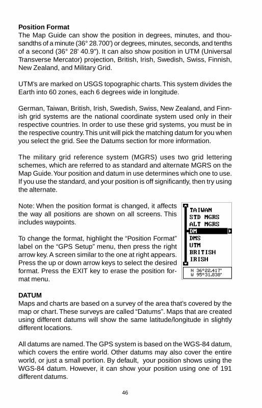
46
Position FormatThe Map Guide can show the position in degrees, minutes, and thou-sandths of a minute (36° 28.700') or degrees, minutes, seconds, and tenthsof a second (36° 28' 40.9"). It can also show position in UTM (UniversalTransverse Mercator) projection, British, Irish, Swedish, Swiss, Finnish,New Zealand, and Military Grid.
UTM’s are marked on USGS topographic charts. This system divides theEarth into 60 zones, each 6 degrees wide in longitude.
German, Taiwan, British, Irish, Swedish, Swiss, New Zealand, and Finn-ish grid systems are the national coordinate system used only in theirrespective countries. In order to use these grid systems, you must be inthe respective country. This unit will pick the matching datum for you whenyou select the grid. See the Datums section for more information.
The military grid reference system (MGRS) uses two grid letteringschemes, which are referred to as standard and alternate MGRS on theMap Guide. Your position and datum in use determines which one to use.If you use the standard, and your position is off significantly, then try usingthe alternate.
Note: When the position format is changed, it affectsthe way all positions are shown on all screens. Thisincludes waypoints.
To change the format, highlight the “Position Format”label on the “GPS Setup” menu, then press the rightarrow key. A screen similar to the one at right appears.Press the up or down arrow keys to select the desiredformat. Press the EXIT key to erase the position for-mat menu.
DATUMMaps and charts are based on a survey of the area that’s covered by themap or chart. These surveys are called “Datums”. Maps that are createdusing different datums will show the same latitude/longitude in slightlydifferent locations.
All datums are named. The GPS system is based on the WGS-84 datum,which covers the entire world. Other datums may also cover the entireworld, or just a small portion. By default, your position shows using theWGS-84 datum. However, it can show your position using one of 191different datums.
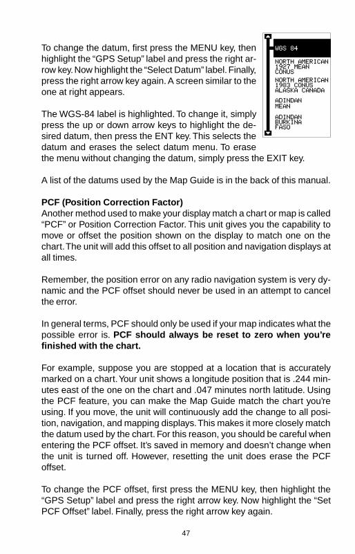
47
To change the datum, first press the MENU key, thenhighlight the “GPS Setup” label and press the right ar-row key. Now highlight the “Select Datum” label. Finally,press the right arrow key again. A screen similar to theone at right appears.
The WGS-84 label is highlighted. To change it, simplypress the up or down arrow keys to highlight the de-sired datum, then press the ENT key. This selects thedatum and erases the select datum menu. To erasethe menu without changing the datum, simply press the EXIT key.
A list of the datums used by the Map Guide is in the back of this manual.
PCF (Position Correction Factor)Another method used to make your display match a chart or map is called“PCF” or Position Correction Factor. This unit gives you the capability tomove or offset the position shown on the display to match one on thechart. The unit will add this offset to all position and navigation displays atall times.
Remember, the position error on any radio navigation system is very dy-namic and the PCF offset should never be used in an attempt to cancelthe error.
In general terms, PCF should only be used if your map indicates what thepossible error is. PCF should always be reset to zero when you’refinished with the chart.
For example, suppose you are stopped at a location that is accuratelymarked on a chart. Your unit shows a longitude position that is .244 min-utes east of the one on the chart and .047 minutes north latitude. Usingthe PCF feature, you can make the Map Guide match the chart you’reusing. If you move, the unit will continuously add the change to all posi-tion, navigation, and mapping displays. This makes it more closely matchthe datum used by the chart. For this reason, you should be careful whenentering the PCF offset. It’s saved in memory and doesn’t change whenthe unit is turned off. However, resetting the unit does erase the PCFoffset.
To change the PCF offset, first press the MENU key, then highlight the“GPS Setup” label and press the right arrow key. Now highlight the “SetPCF Offset” label. Finally, press the right arrow key again.

48
A screen similar to the one at right appears.
Now enter the correction for your location. Remember,this is the difference between the location shown onthe present position display and the position shown onthe chart. In this example, we entered 0 degrees, 0.047minutes north latitude and 0 degrees, 0.244 minuteseast longitude. That is the difference between thepresent position shown by the Map Guide and the oneon our chart.
After you’ve entered the latitude/longitude correction,press the ENT key to accept it. The Map Guide erasesthe PCF entry screen and returns to the navigation ormapping screens with the correction factor applied.
POSITION PINNINGWhen using a GPS receiver at extremely low speeds,it can have trouble determining your course overground, or direction you’re travelling. This is due in largepart to SA, or selective availability. SA is small inaccuracies purposefullyput into the GPS satellite’s signal by the government. This cause widevariations in the track display and other navigation displays when usingthe unit at slow speeds.
If you’re using this receiver without DGPS and stop, the position pinningfeature locks the present position indicator on the plotter until you’ve moveda short distance or exceed a very slow speed. This prevents the “wander-ing” plot trail seen when you’re stopped with position pinning turned off.This also affects the navigational displays.
The easiest way to see the effects of S/A is to stand still with the GPSreceiver turned on and watch your plot trail with position pinning turnedoff. You’ll see the present position change, speed increase and decrease,and a random plot trail on the plotter’s screen.
If you wish to turn the position pinning feature off, press the MENU key,then highlight the “GPS Setup” label and press the right arrow key. Nowhighlight the “Pinning” label. Finally, press the left arrow key.

49
ALARMSThe Map Guide has several alarms. You can set an arrival alarm to flasha warning message and sound a tone when you cross a preset distancefrom a waypoint. For example, if you have the arrival alarm set to .1 mile,then the alarm will flash a message when you come within .1 mile of therecalled waypoint. The course deviation indicator alarm (CDI) can warnswhen your track drifts too far to the right or left of the course line to thewaypoint. For example, if the alarm is set to .1 mile, then the alarm flashesa message if you drift .1 of a mile or more to the right or left of the line tothe waypoint. The anchor alarm is triggered when you drift outside of apreset radius. Again, using the .1 mile as an example, if you’re anchoredand your boat moves more than .1 of a mile, the alarm will flash a mes-sage and sound a tone.
To use any of these alarms, first press the MENU key,then select the “ALARMS/CDI” menu. A screen similarto the one shown at right appears. Press the up or downarrow key to move the black box to the desired alarm,then press the right arrow key to turn it on.
To adjust an alarm’s distance, move the black box tothe alarm’s “DIS” menu item, then press the right or leftarrow keys to increase or decrease the alarm’s dis-tance.
When you’re finished, press the EXIT key to erase this menu.
Important Alarm Notes:Anchor Alarm - Since civilian users don’t receive the accuracy given tomilitary users, the anchor alarm may be triggered even when you’re sit-ting still. This typically happens when using small (less than .05 mile)anchor alarm ranges. If you have a DGPS beacon receiver connected tothe Map Guide, smaller ranges may be usable.
Arrival Alarm - If you set the arrival alarm’s distance to a small number,and you run a route (see the routes section), the Map Guide may notshow navigation data to the next waypoint, once you arrive at the firstone, since you may not be able to come close enough to the first waypointto trip the arrival alarm.
MESSAGESThe DGPS message selections are found on the Alarms/CDI menu shownabove. Pressing the EXIT key erases these messages.

50
The DGPS message appears whenever the unit begins or stops usingDGPS data to help determine your position.
The default setting for these messages is “on”. To turn the message off,select the “Setup Alarms” menu from the main menu, then highlight “DGPSMSG” and press the left arrow key.
SUNRISE/SET MOONRISE/SET CALCULATORThis unit has a sunrise/sunset and moonrise/moonset calculator that showsthis information anywhere or anytime in the world. To use it, press theMENU key, then highlight “SUN/MOON CALC” andpress the right arrow key. Highlight either the sun ormoon calculator and press the right arrow key. Thescreen shown at right appears if you chose the sunrisecalculator. (Both calculators work identically. The sun-rise/sunset calculator is used for this example.) Thesunrise and sunset for today’s date appear in the cen-ter of the screen. Today’s date shows at the top of thescreen. If you want to know the sunrise/sunset for adifferent date, press the ENT key, then enter the newdate with the arrow keys. The unit returns to the sun-rise/sunset calculator screen with the sunrise and sun-set times shown for the date you entered.
The sunrise and sunset show for your present position. If you move theplotter’s cursor to a different position before using this calculator, it willshow the sunrise/sunset for the cursor’s location.
The moonrise/moonset calculator works identically tothe sunrise/sunset calculator. It looks like the screen atright. A moon symbol shows near the bottom of thescreen, showing the approximate phase of the moon.The arrow next to the symbol shows if it is moving to-wards a full moon (up) or a new moon (down).
Press the EXIT key to erase this screen.

51
SIMULATORA simulator is built into this unit that has several options. You can usenearly all of the unit’s features - even save and recall waypoints. This isuseful for trip planning.
To use the simulator, press the MENU key, then pressthe up or down arrow keys until the “SIMULATORSETUP” menu is surrounded by the black box. Nowpress the right arrow key. The screen shown at rightappears.
If you simply press the right arrow key, turning the simu-lator on, the Map Guide will start from your presentposition and follow a track of 355° at 100 miles perhour.
To change either the track or speed, highlight the one you want to change,then press the right or left arrow key. When the numbers are correct,press the EXIT key.
Starting PositionNormally, the starting position for the simulator is yourpresent position. If you want to change the startingposition, highlight the “SET START WPT” label on theSimulator Setup menu, then press the right arrow key.The screen shown at right appears.
You can select any waypoint as the simulator’s startingpoint. Select the starting point by pressing the right ar-row key on the “WPT#” label until the desired startingwaypoint number appears. Now highlight the “SET SIMSTART” label and press the right arrow key. The unit returns to the Simu-lator Setup menu using the specified waypoint as the starting waypoint.
Use Arrow Keys to SteerThis option lets you change both the course and speedon the screen as the simulator is running. To do this,highlight the “STEER WITH ARROWS” label on theSimulator Setup screen, then press the right arrow key.The screen shown at right appears. Use the up anddown arrow keys to increase or decrease the speed.Use the right and left arrow keys to change the track.Press the EXIT key to erase these menus.

52
When you’re finished changing the track and speed, press the EXIT keyto erase the menus.
DEFINITION OF TERMS/ABBREVIATIONSDue to space considerations, the digital displays use abbreviations forsome names. They are as follows:
ALT ............... Altitude - Your height above sea level.BRG ............. Bearing - The direction from your present position to a
waypoint.CDI ............... Course Deviation Indicator - Shows your distance to the
side of the desired course line.CLOCK ......... Your local time.TRK .............. Track - The direction you’re travelling.DIS ............... Distance - Distance remaining between your present po-
sition and a waypoint.DNT/UPT ...... Countdown timer (DNT) and Count up timer (UPT)ETA ............... Estimated Time of ArrivalETE .............. Estimated Time En routeICON ............ A symbol you can place on the map, representing a land-
mark.POSITION .... Your present position.GS ................ Ground Speed - Your actual speed.UTC .............. Coordinated Universal Time - Time at the prime meridian
at Greenwich, England. Formerly known as GMT.VOLTS .......... Electrical system voltage.VMG ............. Velocity Made Good - Your ground speed towards a re-
called waypoint, airport, etc.

53
WGS 84 .................DEFAULT
ADINDAN ...............MEAN
ADINDAN ...............BURKINAFASO
ADINDAN ...............CAMEROON
ADINDAN ...............ETHIOPIA
ADINDAN ...............MALI
ADINDAN ...............SENEGAL
ADINDAN ...............SUDAN
AFGOOYE .............SOMALIA
AIN EL ABD ...........1970BAHRAIN
AIN EL ABD ...........1970 SAUDIARABIA
ANNA 1 ASTRO ....1965 COCOSISLANDS
ANTIGUA ...............ISLANDASTRO 1943
ARC 1950 ..............MEAN
ARC 1950 ..............BOTSWANA
ARC 1950 ..............BURUNDI
ARC 1950 ..............LESOTHO
ARC 1950 ..............MALAWI
ARC 1950 ..............SWAZILAND
ARC 1950 ..............ZAIRE
ARC 1950 ..............ZAMBIA
ARC 1950 ..............ZIMBABWE
WGS 1984Default
AdindanMean for Ethiopia, Sudan
AdindanBurkina Faso
AdindanCameroon
AdindanEthiopia
AdindanMali
AdindanSenegal
AdindanSudan
AfgooyeSomalia
Ain el Abd 1970Bahrain
Ain el Abd 1970Saudi Arabia
Anna 1 Astro 1965Cocos Islands
Antigua Island Astro 1943Antigua (Leeward Islands)
Arc 1950Mean for Botswana, Lesotho,Malawi, Swaziland, Zaire, Zambia,Zimbabwe
Arc 1950 - Botswana
Arc 1950 - Burundi
Arc 1950 - Lesotho
Arc 1950 - Malawi
Arc 1950 - Swaziland
Arc 1950 - Zaire
Arc 1950 - Zambia
Arc 1950 - Zimbabwe
ARC 1960 ..............MEAN
ASCENSION ..........ISLAND1958
ASTRO BEACON ..E 1945IWO JIMA
ASTRO DOS 714 ..ST HELENAISLAND
ASTRO TERN ........ISLAND1961
ASTRONOMICAL ..STATION ‘52MARCUS ISLE
AUSTRALIAN ........GEODETIC1966
AUSTRALIAN ........GEODETIC1984
AYABELLE .............LIGHTHOUSEDJIBOUTI
BELLEVUE ............(IGN) EFATEERRAOMANGO
BERMUDA .............1957
BISSAU ..................GUINEA
BOGOTA ................OBSERVATORYCOLOMBIA
BUKIT RIMPAH ......INDONESIA
CAMP AREA ..........ASTROANTARCTICA
CAMPO ..................INCHAUSPEARGENTINA
CANTON ASTRO ..’66 PHOENIXISLANDS
CAPE .....................SOUTHAFRICA
CAPE .....................CANAVERALBAHAMAS FL
Arc 1960 - Mean for Kenya,Tanzania
Ascension Island 1958 -Ascension Island
Astro Beacon E 1945 - Iwo Jima
Astro DOS 71/4 - St Helena Island
Astro Tern Island (FRIG) 1961 -Tern Island
Astronomical Station 1952 -Marcus Island
Australian Geodetic 1966 -Australia & Tasmania
Australian Geodetic 1984 -Australia & Tasmania
Ayabelle Lightlhouse - Djibouti
Bellevue (IGN) - Efate &Erromango Islands
Bermuda 1957 - Bermuda
Bissau - Guinea-Bissau
Bogota Observatory - Colombia
Bukit Rimpah - Indonesia (Bangka& Belitung Islands)
Camp Area Astro - Antarctica(McMurdo Camp Area)
Campo Inchauspe - Argentina
Canton Astro 1966 - PhoenixIslands
Cape - South Africa
Cape Canaveral - Bahamas,Florida
DATUMS

54
CARTHAGE ...........TUNISIA
CH-1903 ................
CHATHAM .............ISLAND ASTRONEW ZEALAND
CHUA ASTRO .......PARAGUAY
CORREGO ............ALEGREBRAZIL
DABOLA ................GUINEA
DJAKARTA .............(BATAVIA)INDONESIA
DOS 1968 ..............NEW GEORGIAISLANDS
EASTER ................ISLAND1967
EUROPEAN ...........1950 MEANWESTERN
EUROPEAN ...........1950 MEANCENTRAL
EUROPEAN ...........1950 MEANMIDDLE EAST
EUROPEAN ...........1950CYPRUS
EUROPEAN ...........1950EGYPT
EUROPEAN ...........1950 GREATBRITAIN
EUROPEAN ‘50 .....FINLANDNORWAY
EUROPEAN ...........1950GREECE
EUROPEAN ...........1950IRAN
Carthage - Tunisia
Switzerland
Chatham Island Astro 1971New Zealand (Chatham Island)
Chua AstroParaguay
Corrego AlegreBrazil
DabolaGuinea
Djakarta (Batavia)Indonesia (Sumatra)
DOS 1968New Georgia Islands(Gizo Island)
Easter Island 1967Easter Island
European 1950Mean for Austria, Belgium,Denmark, Finland, France,West Germany, Gibralter, Greece,Italy, Luxembourg, Netherlands,Norway, Portugal, Spain, Sweden, Switzerland
European 1950Mean for Austria, Denmark,France, West Germany,Netherlands, Switzerland
European 1950Mean for Iraq, Israel, Jordan,Lebanon, Kuwait,Saudi Arabia, Syria
European 1950Cyprus
European 1950Egypt
European 1950England, Channel Islands, Ireland, Scotland, Shetland Islands
European 1950Finland, Norway
European 1950Greece
European 1950Iran
EUROPEAN ...........1950 ITALY(SARDINIA)
EUROPEAN ...........1950 ITALY(SICILY)
EUROPEAN ...........1950MALTAEUROPEAN ...........1950 SPAINPORTUGAL
EUROPEAN ...........1979MEAN
FORT THOMAS .....1955 NEVISST. KITTS
GAN 1970 ..............REPUBLIC OFMALDIVES
GEODETIC ............DATUM 1949NEW ZEALAND
GRACIOSA ............BASE SW1948 AZORES
GUAM ....................1963
GUNUNG ...............SEGARAINDONESIA
GUX 1 ASTRO .......GUADALCANALISLAND
HERAT NORTH .....AFGHANISTAN
HJORSEY ..............1955ICELAND
HONG KONG ........1963
HU-TZU-SHAN ......TAIWAN
INDIAN ...................BANGLADESH
INDIAN ...................INDIA NEPAL
INDIAN 1954 .........THAILANDVIETNAM
INDIAN 1975 .........THAILAND
European 1950Italy (Sardinia)
European 1950(Sicily)
European 1950Malta
European 1950Portugal, Spain
European 1979Mean for Austria, Finland, Netherlands, Norway, Spain,Sweden, Switzerland
Fort Thomas, 1955Nevis, St. Kitts(Leeward Islands)
Gan 1970Republic of Maldives
Geodeic Datum 1949New Zealand
Graciosa Base SW 1948Azores (Faial, Graciosa, Pico,Sao Jorge, Terceira)
Guam 1963Guam
Gunung SegaraIndonesia (Kalimantan)
GUX 1 AstroGuadalcanal Island
Herat NorthAfghanistan
Hjorsey 1955Iceland
Hong Kong 1963Hong Kong
Hu-Tzu-ShanTaiwan
IndianBangladesh
IndianIndia, Nepal
Indian - 1954Thailand, Vietnam
Indian - 1975Thailand
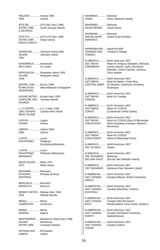
55
IRELAND ...............1965
ISTS 061 ................ASTRO 1968S GEORGIA
ISTS 073 ................ASTRO 1969DIEGO GARCIA
JOHNSTON ...........ISLAND1961
KANDAWALA .........SRI LANKA
KERGUELEN .........ISLAND1949
KERTAU 1948 ........W MALAYSIASINGAPORE
KUSAIE ASTRO ....CAROLINE 1951ISLANDS
L C 5 ASTRO .........1961 CAYMANBRAC ISLAND
LEIGON .................GHANA
LIBERIA .................1964
LUZON ...................PHILIPPINES
LUZON ...................PHILIPPINESMINDANAO
MAHE ISLAND ......1971
MASSAWA .............ETHIOPIA(ERITREA)
MERCHICH ...........MOROCCO
MIDWAY ASTRO ...1961
MINNA ...................CAMEROON
MINNA ...................NIGERIA
MONTSERRAT ......ISLANDASTRO 1958
M’PORALOKO .......GABON
Ireland 1965Ireland
ISTS 061 Astro 1968South Georgia Islands
ISTS 073 Astro 1969Diego Garcia
Johnston Island 1961Johnston Island
KandawalaSri Lanka
Kerguelen Island 1949Kerguelen Island
Kertau 1948West Malaysia & Singapore
Kusaie Astro 1951Caroline Islands
L.C. 5 Astro 1961Cayman Brac Island
LeigonGhana
Liberia 1964Liberia
LuzonPhilipines(Excluding Mindanao)
LuzonPhilipines (Mindanao)
Mahe 1971Mahe Island
MassawaEthiopia (Eritrea)
MerchichMorocco
Midway Astro 1961Midway Islands
MinnaCameroon
MinnaNigeria
Montserrat Island Astro 1958Montserrat(Leeward Islands)
M’PoralokoGabon
NAHRWAN .............OMAN
NAHRWAN .............SAUDI ARABIA
NAHRWAN .............UNITED ARABEMIRATES
NAPARIMA BWI .....TRINIDAD ANDTOBAGO
N AMERICA ...........1927 MEANCARRIBEAN
N AMERICA ...........1927 MEANCENTRAL AMER
N AMERICA ...........1927 MEANCANADA
N AMERICA ...........1927 MEANCONUS
N AMERICA ...........1927 MEANCONUS EAST
N AMERICA ...........1927 MEANCONUS WEST
N AMERICA ...........1927 ALASKA
N AMERICA ...........1927 BAHAMAS(NO SAN SALV)
N AMERICA ...........1927 BAHAMAS
N AMERICAN ........1927 CANADA(WEST)
N AMERICAN ........1927 CANADA(CENTRAL)
N AMERICAN ........1927 CANADAEAST
N AMERICAN ........1927 CANADANORTH
N AMERICAN ........1927 CANADAYUKON
NahrwanOman (Masirah Island)
NahrwanSaudi Arabia
NahrwanUnited Arab Emirates
Naparima BWITrinidad & Tobago
North American 1927Mean for Antigua, Barbados, Barbuda,Caicos Islands, Cuba, DominicanRepublic, Grand Cayman, Jamaica,Turks Islands
North American 1927Mean for Belize, Costa Rica,El Salvador, Guatmala, Honduras,Nicaragua
North American 1927Mean for Canada
North American 1927Mean for CONUS(Continental United States)
North American 1927Mean for CONUS (East of MississippiRiver) including Louisiana, Missouri,Minnesota
North American 1927Mean for CONUS(West of Mississippi River)
North American 1927Alaska
North American 1927Bahamas(Except San Salvador Island)
North American 1927Bahamas (San Salvador Island)
North American 1927Canada (Alberta, British Columbia)
North American 1927Canada (Manitoba, Ontario)
North American 1927Canada (New Brunswick,Newfoundland, Nova Scotia, Quebec)
North American 1927Canada (Northwest Territories,Saskatchewan)
North American 1927Canada (Yukon)
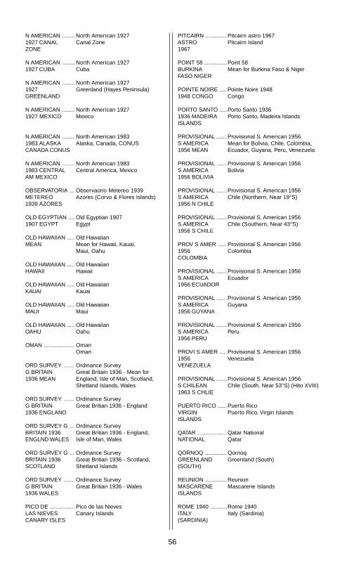
56
N AMERICAN ........1927 CANALZONE
N AMERICAN ........1927 CUBA
N AMERICAN ........1927GREENLAND
N AMERICAN ........1927 MEXICO
N AMERICAN ........1983 ALASKACANADA CONUS
N AMERICAN ........1983 CENTRALAM MEXICO
OBSERVATORIA ...METEREO1939 AZORES
OLD EGYPTIAN ....1907 EGYPT
OLD HAWAIIAN .....MEAN
OLD HAWAIIAN .....HAWAII
OLD HAWAIIAN .....KAUAI
OLD HAWAIIAN .....MAUI
OLD HAWAIIAN .....OAHU
OMAN ....................
ORD SURVEY .......G BRITAIN1936 MEAN
ORD SURVEY .......G BRITAIN1936 ENGLAND
ORD SURVEY G ...BRITAIN 1936ENGLND WALES
ORD SURVEY G ...BRITAIN 1936SCOTLAND
ORD SURVEY .......G BRITAIN1936 WALES
PICO DE ................LAS NIEVESCANARY ISLES
PITCAIRN ..............ASTRO1967
POINT 58 ...............BURKINAFASO NIGER
POINTE NOIRE .....1948 CONGO
PORTO SANTO .....1936 MADEIRAISLANDS
PROVISIONAL .......S AMERICA1956 MEAN
PROVISIONAL .......S AMERICA1956 BOLIVIA
PROVISIONAL .......S AMERICA1956 N CHILE
PROVISIONAL .......S AMERICA1956 S CHILE
PROV S AMER ......1956COLOMBIA
PROVISIONAL .......S AMERICA1956 ECUADOR
PROVISIONAL .......S AMERICA1956 GUYANA
PROVISIONAL .......S AMERICA1956 PERU
PROVI S AMER .....1956VENEZUELA
PROVISIONAL .......S CHILEAN1963 S CHLIE
PUERTO RICO ......VIRGINISLANDS
QATAR ...................NATIONAL
QORNOQ ..............GREENLAND(SOUTH)
REUNION ..............MASCARENEISLANDS
ROME 1940 ...........ITALY(SARDINIA)
North American 1927Canal Zone
North American 1927Cuba
North American 1927Greenland (Hayes Peninsula)
North American 1927Mexico
North American 1983Alaska, Canada, CONUS
North American 1983Central America, Mexico
Observaorio Metereo 1939Azores (Corvo & Flores Islands)
Old Egyptian 1907Egypt
Old HawaiianMean for Hawaii, Kauai,Maui, Oahu
Old HawaiianHawaii
Old HawaiianKauai
Old HawaiianMaui
Old HawaiianOahu
OmanOman
Ordinance SurveyGreat Britain 1936 - Mean forEngland, Isle of Man, Scotland,Shetland Islands, Wales
Ordinance SurveyGreat Britian 1936 - England
Ordinance SurveyGreat Britian 1936 - England,Isle of Man, Wales
Ordinance SurveyGreat Britian 1936 - Scotland,Shetland Islands
Ordinance SurveyGreat Britian 1936 - Wales
Pico de las NievesCanary Islands
Pitcairn astro 1967Pitcairn Island
Point 58Mean for Burkina Faso & Niger
Pointe Noire 1948Congo
Porto Santo 1936Porto Santo, Madeira Islands
Provisional S. American 1956Mean for Bolivia, Chile, Colombia,Ecuador, Guyana, Peru, Venezuela
Provisional S. American 1956Bolivia
Provisional S. American 1956Chile (Northern, Near 19°S)
Provisional S. American 1956Chile (Southern, Near 43°S)
Provisional S. American 1956Colombia
Provisional S. American 1956Ecuador
Provisional S. American 1956Guyana
Provisional S. American 1956Peru
Provisional S. American 1956Venezuela
Provisional S. American 1956Chile (South, Near 53°S) (Hito XVIII)
Puerto RicoPuerto Rico, Virgin Islands
Qatar NationalQatar
QornoqGreenland (South)
ReunionMascarene Islands
Rome 1940Italy (Sardinia)

57
RT 90 .....................
SANTO (DOS) .......’65 ESPIRITOSANTO ISLAND
SAO BRAZ .............AZORES
SAPPER HILL ........1943 EASTFALKLND ISLE
SCHWARZECK .....NAMIBIA
SELVAGEMGRANDESALVAGE ISLE
SOVIET ..................GEODETICSYSTEM 1985
S AMERICAN ........1969 MEAN
S AMERICAN ........1969ARGENTINA
S AMERICAN ........1969 BOLIVIA
S AMERICAN ........1969 BRAZIL
S AMERICAN ........1969 CHILE
S AMERICAN ........1969COLOMBIA
S AMERICAN ........1969ECUADOR
S AMERICAN ........1969 ECUADORGALAPAGOS
S AMERICAN ........1969 GUYANA
S AMERICAN ........1969PARAGUAY
S AMERICAN ........1969 PERU
S AMERICAN ........1969 TOBAGOAND TRINIDAD
S AMERICAN ........1969VENEZUELA
Sweden
Santo (DOS)1965 Espirito Santo Island
Sao BrazAzores (Sao Miguel,Santa Maria Islands)
Sapper Hill 1943East Falkland Island
SchwarzeckNambia
Selvagem GrandeSalvage Islands
SGS 85Soviet Geodetic System 1985
South American 1969Mean for Argentina, Bolivia,Brazil, Chile, Colombia, Ecuador,Guyana, Paraguay, Peru,Trinidad & Tobago, Venezuela
South American 1969Argentina
South American 1969Bolivia
South American 1969Brazil
South American 1969Chile
South American 1969Colombia
South American 1969Ecuador
South American 1969Ecuador (Baltra, Galapagos)
South American 1969Guyana
South American 1969Paraguay
South American 1969Peru
South American 1969Trinidad & Tobago
South American 1969Venezuela
SOUTH ASIA .........
SINGAPORE .........
TANANARIVE ........OBSERVATORY1925MADAGASCAR
TIMBALAI ..............1948 BRUNEIE MALAYSIA
TOKYO ...................MEAN
TOKYO ...................JAPAN
TOKYO ...................KOREA
TOKYO ...................
OKINAWA ..............
TRISTAN DA ..........CUNHAASTRO 1968
VITI LEVU ..............1916 FIJI
WAKE ....................
ENIWETOK ‘60 ......
MARSHALL ISL .....
WAKE ISLAND ......ASTRO 1952
WGS 1972 .............GLOBALDEFINITION
YACARE .................URUGUAY
ZANDERIJ .............SURINAME
South Asia
Singapore
Tananarive Observatory 1925Madagascar
Timbalai 1948Brunei, East Malaysia(Sabah, Sarawak)
TokyoMean for Japan, Korea, Okinawa
TokyoJapan
TokyoKorea
Tokyo
Okinawa
Tristan Astro 1968Tristan da Cunha
Viti Levu 1916Fiji (Viti Levu Island)
Wake
Eniwetok 1960
Marshall Islands
Wake Island Astro 1952Wake Atoll
WGS 1972Global Definition
YacareUruguay
ZanderijSuriname

58
Eagle's UPS Return Service - U.S.A. OnlyEagle Electronics and United Parcel Service (UPS) are proud to offer allof our customers free shipping for all units sent to us for repair or service.If you have to send this unit to the factory, and you are in the continentalUnited States, use the enclosed UPS shipping label for easy, free ship-ping to our factory customer service department. There are six easysteps:
1. Call Eagle at the toll-free number on the back of this manual for aReturn Authorization (RA) number and instructions about what acces-sories to return. Do not return a product to the factory without aReturn Authorization (RA) Number!
2. Pack your unit and any accessories in the original shipping container,if possible. Be sure to include proof of purchase for warranty veri-fication!
3. Write a brief note detailing the problem you're having with the unit.Please include your name, address, and daytime telephone number.
4. Please include payment for non-warranty repairs. Check, money order,Visa, or MasterCard may be used.
5. Fill in your name, address, zip code, date, and RA number in the blanksprovided on the UPS form included with your unit.
6. Attach the label to the shipping box, tear off the tab for your receiptand give the package to any UPS driver or take the package to anyUPS Customer Center. You will not be charged for this shipment.
That's it! Your unit will be shipped to Eagle's customer service departmentat no charge to you. Units under warranty will be returned to you at nocharge.
NOTE!Eagle will pay UPS surface shipping charges both to and from the factoryfor this unit in the event it needs repair. Your unit is insured against loss orshipping damage when you use the enclosed UPS label.
This UPS shipping offer is good only in the continental United States (ex-cludes Alaska and Hawaii).

59
KEEP THIS LABEL!YOU WILL NEED IT IF YOU EVER NEED TO RETURN YOUR UNIT TO
THE FACTORY FOR REPAIR.
Accessory Ordering InformationTo order accessories such as power cables, please contact:
1) Your local marine dealer. Most quality dealers that handle marine elec-tronic equipment should be able to assist you with these items. Consultyour local telephone directory for listings.
2) LEI Extras, Inc. P.O. Box 129 Catoosa, OK 74015-0129or call
800-324-0045(USA orders only.)
Eagle Electronics may find it necessary to change or end our shippingpolicies, regulations, and special offers at any time. We reserve the rightto do so without notice.

60
EAGLE ELECTRONICSFULL ONE-YEAR WARRANTY
“We", “our”, or “us” refers to EAGLE ELECTRONICS, a division of LEI, the manufacturer ofthis product. “You” or “your” refers to the first person who purchases this product as aconsumer item for personal, family, or household use.
We warrant this product against defects or malfunctions in materials and workmanship,and against failure to conform to this product’s written specifications, all for one year (1)from the date of original purchase by you. WE MAKE NO OTHER EXPRESS WARRANTYOR REPRESENTATION OF ANY KIND WHATSOEVER CONCERNING THIS PRODUCT.Your remedies under this warranty will be available so long as you can show in a reason-able manner that any defect or malfunction in materials or workmanship, or any non-conformity with the product’s written specifications, occurred within one year from the dateof your original purchase, which must be substantiated by a dated sales receipt or salesslip. Any such defect, malfunction, or non-conformity which occurs within one year fromyour original purchase date will either be repaired without charge or be replaced with anew product identical or reasonably equivalent to this product, at our option, within a rea-sonable time after our receipt of the product. If such defect, malfunction, or non-conformityremains after a reasonable number of attempts to repair by us, you may elect to obtainwithout charge a replacement of the product or a refund for the product. THIS REPAIR,REPLACEMENT, OR REFUND (AS JUST DESCRIBED) IS THE EXCLUSIVE REMEDYAVAILABLE TO YOU AGAINST US FOR ANY DEFECT, MALFUNCTION, OR NON-CON-FORMITY CONCERNING THE PRODUCT OR FOR ANY LOSS OR DAMAGE RESULT-ING FROM ANY OTHER CAUSE WHATSOEVER. WE WILL NOT UNDER ANY CIR-CUMSTANCES BE LIABLE TO ANYONE FOR ANY SPECIAL, CONSEQUENTIAL, INCI-DENTAL, OR OTHER INDIRECT DAMAGE OF ANY KIND.
Some states do not allow the exclusion or limitation of incidental or consequential dam-ages, so the above limitations or exclusions may not apply to you.
This warranty does NOT apply in the following circumstances: (1) when the product hasbeen serviced or repaired by anyone other than us, (2) when the product has been con-nected, installed, combined, altered, adjusted, or handled in a manner other than accord-ing to the instructions furnished with the product, (3) when any serial number has beeneffaced, altered, or removed, or (4) when any defect, problem, loss, or damage has re-sulted from any accident, misuse, negligence, or carelessness, or from any failure to pro-vide reasonable and necessary maintenance in accordance with the instructions of theowner’s manual for the product.
We reserve the right to make changes or improvements in our products from time to timewithout incurring the obligation to install such improvements or changes on equipment oritems previously manufactured.
This warranty gives you specific legal rights and you may also have other rights which mayvary from state to state.
REMINDER: You must retain the sales slip or sales receipt proving the date of your origi-nal purchase in case warranty service is ever required.
This warranty does not apply to any database or its contents supplied initially with thisproduct. For warranty information on the databases and their contents, please refer to the“Databases Limited Warranty” included with this product.
EAGLE ELECTRONICS PO BOX 669 CATOOSA, OK 74015
61
EAGLE DATABASES LICENSE AGREEMENT
THIS IS A LEGAL AGREEMENT BETWEEN THE END-USER WHOFIRST PURCHASES THIS PRODUCT AS A CONSUMER ITEM FORPERSONAL, FAMILY, OR HOUSEHOLD USE (“YOU”) AND EAGLEELECTRONICS, A DIVISION OF LEI, THE MANUFACTURER OF THISPRODUCT. (“WE”, “OUR”, OR “US”). USING THE PRODUCT ACCOM-PANIED BY THIS LICENSE AGREEMENT CONSTITUTES ACCEP-TANCE OF THESE TERMS AND CONDITIONS. IF YOU DO NOT AC-CEPT ALL TERMS AND CONDITIONS, PROMPTLY RETURN THEPRODUCT WITHIN 30 DAYS OF PURCHASE. PLEASE RETURN US-ING THE ENCLOSED UPS SHIPPING LABEL AND INCLUDE: PROOFOF PURCHASE, NAME, ADDRESS, AND PHONE NUMBER. YOURPURCHASE PRICE AND ANY APPLICABLE TAXES WILL BE RE-FUNDED. PLEASE ALLOW 4-6 WEEKS TO PROCESS YOUR REFUND.
1. This License Agreement applies to the one or more databases thatyour product may contain. We refer to these singly as a “Database”and together as the “Databases.” Your product may thus include the“WBS Database” which contains worldwide background surface map-ping data, the “SmartMap Database” which contains inland mappingdata, or other Databases.
2. The Databases that your product may contain are licensed, not sold.We grant to you the nonexclusive, nonassignable right to use theseDatabases for supplemental navigation reference purposes, but onlyas long as you comply with the terms and conditions of this LicenseAgreement. We reserve the right to terminate this license if you violateany aspect of this License Agreement. You are responsible for usingofficial government charts and prudent navigation for safe travel.
3. The Databases housed in your product are protected by the copyrightnotices appearing on the product or its screen(s). You may NOT modify,adapt, translate, reverse engineer, decompile, disassemble, rent, lease,or resell any Database, and you may NOT create derivative worksbased upon any Database or its contents.. Any unauthorized repro-duction, use, or transfer of a Database may be a crime and may sub-ject you to damages and attorney fees.
4. This License Agreement will terminate immediately without prior no-tice from us if you fail to comply with or violate any of the provisions ofthis Agreement. Upon termination, you will promptly return all prod-ucts containing one or more Databases to us.
5. Prices and programs are subject to change without notice.
6. This License Agreement shall be governed by the laws of the State ofOklahoma and comprises the complete and exclusive understandingbetween you and us concerning the above subject matter.

62
DATABASES LIMITED WARRANTY
“We”, “our”, or “us” refers to Eagle Electronics, a division of LEI, the manufacturer of thisproduct. “You” or “your” refers to the first person who purchases the product as a consumeritem for personal, family, or household use. The Databases Limited Warranty applies to theone or more databases that your product may contain. We refer to each of these as a“Database” or together as the “Databases.” Your product may thus include the “WBS Data-base” which contains worldwide background surface mapping data, the “SmartMap Data-base” which contains inland mapping data, or other Databases.
We warrant to you that we have accurately compiled, processed, and reproduced theportions of the source material on which the Databases are based. However, we are underno obligation to provide updates to the Databases, and the data contained in the Data-bases may be incomplete when compared to the source material. WE MAKE NO EX-PRESS OR IMPLIED WARRANTY OF ANY KIND ABOUT THE ACCURACY OF THESOURCE MATERIAL ITSELF, INCLUDING BUT NOT LIMITED TO IMPLIED WARRAN-TIES OF MERCHANTABILITY OR FITNESS FOR A PARTICULAR PURPOSE.
If there is a defect in any Database, your exclusive remedy shall be, at our option, either arefund of the price you paid for the product containing the defective Database or a replace-ment of such product. WE WILL NOT UNDER ANY CIRCUMSTANCES BE LIABLE TOANYONE FOR ANY SPECIAL, CONSEQUENTIAL, INCIDENTAL, OR OTHER INDIRECTDAMAGE OF ANY KIND.
Some states do not allow the exclusion or limitation of incidental or consequential dam-ages, so the above limitations or exclusions may not apply to you.
This warranty does NOT apply in the following circumstances: (1) when the product hasbeen serviced or repaired by anyone other than us, (2) when the product has been con-nected, installed, combined, altered, adjusted, or handled in a manner other than accord-ing to the instructions furnished with the product, (3) when any serial number has beeneffaced, altered, or removed, or (4) when any defect, problem, loss, or damage has re-sulted from any accident, misuse, negligence, or carelessness, or from any failure to pro-vide reasonable and necessary maintenance in accordance with the instructions of theowner’s manual for the product.
We reserve the right to make changes or improvements in our products from time to timewithout incurring the obligation to install such improvements or changes on equipment oritems previously manufactured.
This warranty gives you specific legal rights and you may also have other rights which mayvary from state to state.
Your remedies under this warranty will be available so long as you can show in a reason-able manner that the defect occurred within one (1) year from the date of your originalpurchase, and we must receive your warranty claim no later than 30 days after such 1-yearperiod expires. Your claim must be substantiated by a dated sales receipt or sales slip.

63

64
How to Obtain Service(Canadian Customers Only)We back your investment in quality products with quick, expert service and genuineEagle replacement parts. If you need service or repairs, contact the Eagle FactoryCustomer Service Department at the toll-free number listed below. A technician may beable to solve the problem and save you the inconvenience of returning your unit. You willbe asked for your unit's serial number.
800-324-1354Canada Only. Monday through Friday 8:00 A.M. - 8:00 P.M. Central Time.
When sending a product for repair, please do the following:1. Always use the original shipping container and filler material the product was packed
in when shipping your product.
2 Always insure the parcel against damage or loss during shipment. Eagle does notassume responsibility for goods lost or damaged in transit.
3. For proper testing, repair, and service, send a brief note with the product describingthe problem. Be sure to include your name, return shipping address, and a daytimetelephone number.
How to Obtain Service(International Customers Only - Except Canada)
If you need service or repairs, contact the dealer in the country you purchased yourunit.
WARRANTY REPAIR WILL BE HONORED ONLY IN THECOUNTRY UNIT WAS PURCHASED.
Please follow the shipping instructions shown below on this page if you have to mailyour unit to the dealer. For proper testing, repair, and service, send a brief note with theproduct describing the problem. Be sure to include your name, return shipping ad-dress, and a daytime telephone number.
Accessory Ordering Information - All CountriesTo order accessories such as power cables or transducers, please contact:1. Your local dealer. Most quality dealers that handle GPS navigation equipment
should be able to assist you with these items. Consult your local telephone direc-tory for listings.
2. Canadian customers only can write:Lowrance/Eagle Canada, 919 Matheson Blvd., E. Mississauga, Ontario L4W2R7
or fax 416-629-3118

65
How to Obtain Service - U.S.A. OnlyWe back your investment in quality products with quick, expert serviceand genuine Eagle® replacement parts. If you're in the United States andyou have questions, please contact the Factory Customer Service De-partment using our toll-free number listed below. You must send the unitto the factory for warranty service or repair. Please call the factory beforesending the unit. You will be asked for your unit's serial number. Use thefollowing toll-free number:
800-324-1354U.S.A.only. Monday through Friday 8:00 A.M. - 8:00 P.M. Central time, except holidays.
Your unit is covered by a full one-year warranty. (See page 60 inside thismanual for complete warranty details.) If your unit fails and the failure isnot covered by the original warranty, Eagle has a flat-rate repair policythat covers your unit and accessories packed with the unit at the factory.There is a 180-day warranty on all non-warranty repairs from the factory,which is similar to the original warranty, but is for 180 days rather than oneyear. For further details, please call us at the above number.
Eagle also gives you free UPS shipping from anywhere in the continentalUnited States both to and from the factory for all warranty repairs. You canalso use the enclosed UPS shipping label for non-warranty shipments.See page 58 for more information. Remember, non-warranty repairs aresubject to Eagle's published flat-rate charges and 180-day warranty.
LITHO IN U.S.A. 988-0145-70