Embed Size (px)
Citation preview

INSTALLATION ANDOPERATION INSTRUCTIONS
Eagle ViewTM
®

Copyright © 1996, 1997 Eagle ElectronicsAll rights reserved.
Eagle View™ is a trademark of Eagle ElectronicsEagle® is a registered trademark of Eagle Electronics
WARNING!USE THIS UNIT ONLY AS AN AID TO NAVIGATION. A CAREFUL NAVI-GATOR NEVER RELIES ON ONLY ONE METHOD TO OBTAIN POSI-TION INFORMATION.
Never use this product while operating a vehicle.
CAUTIONWhen showing navigation data to a position (waypoint), this unit will showthe shortest, most direct path to the waypoint. It provides navigation datato the waypoint regardless of obstructions. Therefore, the prudent naviga-tor will not only take advantage of all available navigation tools when trav-elling to a waypoint, but will also visually check to make certain a clear,safe path to the waypoint is always available.
The storage temperature for your unit is from -4 degrees to +167 degreesFahrenheit (-20 to +75 degrees Celsius). Extended storage temperatureshigher or lower than specified will cause the liquid crystal display to fail.Neither this type of failure nor its consequences are covered by the war-ranty. For more information, consult the factory customer service depart-ment.
All features and specifications subject to change without notice.
Eagle Electronics may find it necessary to change or end our policies,regulations, and special offers at any time. We reserve the right to do sowithout notice.
All screens in this manual are simulated.

INTRODUCTION .......................................................................................................... 1INSTALLATION ............................................................................................................. 2
BRACKET INSTALLATION ...................................................................................... 2POWER CABLE ...................................................................................................... 4ANTENNA ................................................................................................................ 5
SURFACE MOUNT ............................................................................................ 5MAGNET MOUNT .............................................................................................. 6POLE MOUNT .................................................................................................... 6
KEYBOARD .................................................................................................................. 7OPERATION ................................................................................................................. 8
TURNING POWER ON ........................................................................................... 8MENUS .................................................................................................................... 8FINDING YOUR POSITION ..................................................................................... 8
COLD START ..................................................................................................... 8INITIALIZATION ................................................................................................. 9
POSITION/NAVIGATION DISPLAYS ...................................................................... 11NAVIGATION SCREENS ................................................................................... 12
PLOTTER SCREENS .............................................................................................. 14PLOTTER CURSOR .......................................................................................... 15PLOTTER OPTIONS .......................................................................................... 15
TRAIL RECORD ............................................................................................ 16PLOTTER ORIENTATION ............................................................................. 16PLOTTER UPDATE RATE ............................................................................. 17GRID LINES ................................................................................................... 18
ICONS ................................................................................................................ 18PLACE ICON - CURSOR LOCATION ........................................................... 18ERASE ICONS .............................................................................................. 19
WINDOWS ............................................................................................................... 20SPECIAL WINDOWS ......................................................................................... 20
SATELLITE INFORMATION SCREEN .......................................................... 20COURSE DEVIATION INDICATOR (CDI) ..................................................... 21CLOCK ........................................................................................................... 22CLOCK SET ................................................................................................... 22CLOCK ALARM ............................................................................................. 22TIMERS ......................................................................................................... 23
REPROGRAM BOXES ............................................................................................ 23WAYPOINTS ............................................................................................................ 24
SAVING YOUR PRESENT POSITION (QUICK SAVE) ..................................... 24SAVING CURSOR POSITION ........................................................................... 25SAVING YOUR PRESENT POSITION .............................................................. 25EDIT WAYPOINT LAT/LON ................................................................................ 26EDIT WAYPOINT NAME .................................................................................... 27MOVE A WAYPOINT .......................................................................................... 27DISTANCE BETWEEN WAYPONTS ................................................................. 28WAYPOINT OPTIONS ....................................................................................... 29DELETE A WAYPOINT ...................................................................................... 29
ROUTES .................................................................................................................. 30CREATE A ROUTE ............................................................................................ 30
SELECT WAYPOINTS FOR ROUTE ............................................................ 31FINISHING THE ROUTE ............................................................................... 32DELETE A WAYPOINT FROM ROUTE ........................................................ 32VIEW WAYPOINT DETAIL ............................................................................. 32
FOLLOW A ROUTE ........................................................................................... 32SKIP A WAYPOINT IN A ROUTE .................................................................. 34
DELETE A ROUTE ............................................................................................ 34

NAVIGATION ................................................................................................................ 35NAVIGATE TO A WAYPOINT .................................................................................. 35NAVIGATE TO A CURSOR LOCATION .................................................................. 35NAVIGATING TO A WAYPOINT USING THE PLOTTER........................................ 36CANCEL NAVIGATION ........................................................................................... 36
SYSTEM SETUP .......................................................................................................... 37SPEAKER ON/OFF ................................................................................................. 37CONTRAST ADJUST .............................................................................................. 37UNITS OF MEASURE ............................................................................................. 37POSITION FORMAT ................................................................................................ 38NMEA/DGPS ........................................................................................................... 39
NMEA OUTPUT ................................................................................................. 40DGPS .................................................................................................................. 40SERIAL COMMUNICATION SETUP ................................................................. 42
RESET OPTIONS ................................................................................................... 42RESET GROUPS .................................................................................................... 43SYSTEM INFO ........................................................................................................ 43
GPS SETUP ................................................................................................................. 43EXECUTE GPS COLD START ............................................................................... 43DATUM ..................................................................................................................... 44PCF ....................................................................................................................... 45POSITION PINNING ............................................................................................... 46
ALARMS ....................................................................................................................... 46MESSAGES.................................................................................................................. 47BACKLIGHT ................................................................................................................. 47SIMULATOR ................................................................................................................. 48
STARTING POSITION ............................................................................................. 48USER ARROW KEYS TO STEER .......................................................................... 48
DEFINITION OF TERMS/ABBREVIATIONS ............................................................... 49WINDOW GROUPS ..................................................................................................... 50UPS RETURN SERVICE ............................................................................................. 52WARRANTY STATEMENT ........................................................................................... 54ANTENNA MODULE TEMPLATE ................................................................................ 55HOW TO OBTAIN SERVICE - INTERNATIONAL ........................... INSIDE BACK COVERHOW TO OBTAIN SERVICE - U.S.A. ONLY ................................................BACK COVER

1
Congratulations!You have purchased one of the finest 12-channel GPS receivers Eagle™has ever made. With its large LCD screen, easy to use menus, and out-standing performance, we think you’ll be happy with your Eagle View™for many years.
GPS works from satellites that transmit information to the world at veryhigh frequencies. One disadvantage to this frequency is that it’s “line-of-sight”. In other words, the signals don’t bounce around like your localradio or television. If you don’t have a clear view of the sky, or if you’reinside a metal boat dock or garage, the unit probably won’t be able to pickup the signals from the satellites. This is common among all GPS receiv-ers.
Like most GPS receivers, your Eagle View doesn’t have a compass orany other navigation aid built into it. It relies solely on the signals from thesatellites to determine its position. Speed, direction of travel, and distanceare all calculated from position information. Therefore, in order for it todetermine the direction you’re travelling, you must be moving, and thefaster - the better. This is not to say the unit won’t work at walking speeds- it will. But the faster you travel, the easier it is for the unit to determineyour direction.
Another factor that influences the GPS’ position and navigation capabili-ties is called selective availability or S/A. This is small errors purposefullyinjected into the transmitted signal from the satellites. The governmentdoes this to degrade the system’s accuracy to civilian and foreign users.Even with S/A, GPS is the most accurate navigation system ever inventedon such a large scale. The Government’s accuracy specification is 100meters horizontally and 150 meters vertically 95% of the time. In otherwords, the position shown on your Eagle View could be up to 100 metersin any direction from your actual position, and the altitude could be plus orminus 150 meters from what’s shown on the screen, 95% of the time.
There are two ways around the S/A problem. One is to have the govern-ment simply turn it off. In fact, there is growing pressure on them to dothat, but it’s not likely to happen anytime soon. The other method is topurchase a DGPS receiver and connect it to your Eagle View. A DGPSreceiver (commonly called a beacon receiver), picks up correction sig-nals broadcast from ground stations. The Eagle View takes these correc-tions and applies them to the position and altitude screens, giving youmuch better accuracy.
Even with S/A on, and without a DGPS receiver, your Eagle View gives

2
you outstanding position and navigation information. Most people areamazed when they actually use a GPS receiver and see what it does.
Please sit down with the unit and this manual and familiarize yourself withthem before using the Eagle View in the “real world”. A simulator is built in,which lets you practice.
INSTALLATIONINSTALLATION - BracketYou can install the Eagle View on the top of a dash or from an overheadwith the supplied bracket. It can also be installed in the dash with anoptional IDA-3 mounting kit. A swivel bracket is included that converts theEagle View's gimbal bracket to a swivel mount. You can mount the EagleView in any convenient location, provided there is clearance when it’s tiltedfor the best viewing angle.
Bracket Installation - No SwivelHoles in the bracket’s base allow wood screw or through bolt mounting. Itmay be necessary to place a piece of plywood on the back side of thinpanels to reinforce the panel. Make certain there is enough room behindthe unit to attach the power and antenna cables.
Drill a hole in the dash for the power and antenna cables. The best locationfor this hole is immediately under the gimbal bracket. This way, the bracketcovers the hole. The smallest hole the power and antenna cable connectorcan pass through is 3/4". Route the cables to the unit by passing themthrough the hole from under the dash. Slide the bracket over the hole, thenroute the cables out the slot in the back of the bracket. Finally, fasten thebracket to the dash.
Bracket Installation - With Swivel1. Place the swivel bracket on the dash or console in the desired mounting
location. Make certain there is enough room for the unit to rotate. Usingthe swivel bracket’s base as a template, mark the four mounting holesfor drilling. Remove the bracket and drill the holes in the mountingsurface for the #10 mounting screws.
2. Install the large locknut into the bottom of the swivel bracket. Place theswivel bracket onto the mounting surface and attach it using the foursupplied #10 screws.
3. Pass the large screw through the gimbal bracket and the swivel bracket.Thread it into the large locknut and tighten it. Don't tighten it too tight,or the gimbal bracket won't swivel.

3
Gimbal Bracket
Washer
Gimbal Knob
Eagle View
Attach the Eagle View to the gimbal bracket using the supplied gimbalknobs and washers as shown below.

4
WHITE
TOEAGLE VIEW
2-AMPFUSE
GREEN
BLACK
RED
12-VOLTBATTERY
EAGLE VIEWTRANSMIT
(NMEA)
EAGLE VIEWRECEIVE(NMEA)
POWERThe Eagle View will operate from a 12-volt DC system. (9 to 15 volts DC.)You can connect the power cable to an accessory buss under the dash,however, to keep electrical noise interference to a minimum, we recom-mend you wire the power cable directly to the battery through the sup-plied 2-amp fuse.
CAUTION!Do not connect this product to a power source without using a fuse!Failure to use the fuse can cause damage to your unit and will void thewarranty.
Follow the wiring diagram below. If the wires on the power cable are notlong enough to reach the battery, use 18 gauge wire to lengthen the powercable.
The power cable’s green wire is used to receive data from a DGPS re-ceiver. The white wire is used to transmit data to a DGPS receiver or otherelectronic equipment. If you are not connecting the Eagle View to anotherdevice, tape the ends of these wires and secure them where they will notshort to one another. See the NMEA/DGPS section in this manual formore information.
(Note: If your power cable has six wires, tape and secure the extra wires,also. They are not used on this product.)

5
ANTENNAThe Eagle View’s antenna can be mounted on any flat surface, providedyou have access behind the surface for the mounting screws. A magnet isalso supplied that can be epoxied to the bottom of the antenna, allowing itto be used on off-road vehicles. A pole mount adapter lets you mount theantenna on a pole or swivel mount.
ANTENNA INSTALLATIONSurface MountThe Eagle View’s antenna can be easily installed on any flat surface thatis at least 90 mm (3 1/2”) wide. Make certain that a clear view of the sky isavailable at the selected location. Since the GPS signals travel “line-of-sight”, nearly anything blocking the antenna can potentially obstruct theunit from finding a satellite.
Once you’ve determined the mounting location, use the template on page51 in this manual to drill the holes for the screws. The screws, suppliedwith the Eagle View, are 4mm x 30mm. (about 1 1/8” long). Drill 4.75 mm(3/16”) holes for the mounting screws. If you route the cable through themounting surface, you’ll need to drill a 25 mm (1”) hole for the cable.There is a notch in the antenna housing that allows the cable to passthrough to the outside, instead of routing it through the mounting surface.

6
After drilling the holes, pass the o-ring over the antenna cable and pressit into the groove on the bottom of the antenna housing. Now attach theantenna to the mounting surface, using 4mm screws and the suppliedlock washers. Route the cable to the Eagle View and the antenna installa-tion is finished.
Magnet MountA magnet lets you temporarily mount the antenna on any ferrous metalsurface. (such as a car) To use the magnet, simply epoxy it to the bottomof the antenna, using the epoxy supplied with your Eagle View. Carefullyfollow the instructions on the epoxy package and apply it to the magnet.Then carefully press the magnet to the bottom of the antenna housing.After the epoxy cures (in about 30 minutes), the antenna is ready for use.
MAGNET
Pole MountThe Eagle View’s antenna attaches to thepole mount adapter with the supplied 4 mmscrews. You can route the antenna cablethrough the slot in the side of the antenna,or pass it down through the pole mountadapter. A slot next to the threads in thepole mount adapter places the cable nextto the pole where it can be easily routeddown the pole to the Eagle View. Thethreads on the pole mount adapter accepta standard marine antenna mount.
POLE MOUNT

7
KEYBOARDThe keyboard has twelve keys. The arrow keys are tied to most of thefeatures, letting you easily move the plotter’s cursor, navigate through themenus, make selections from menus, and other tasks.
The WPT key lets you create, save, and recall waypoints and routes. TheMODE key switches the unit between the three major displays: windows,navigation, and plotter. To select different features, or to modify functions,press the MENU key. The Z-IN and Z-OUT keys zoom-in and zoom-outyour view on the plotter screen. The ENT and EXIT keys let you enter orerase selections. The PWR key turns the Eagle View on and off.
Note: To prevent an accidental power shutdown, you must hold the PWRkey down for a few seconds in order to turn the unit off.
Z-IN
Z-OUT
MODE
MENU
WPT
EXIT
ENT
PWR

8
OPERATIONTurning Power OnTo turn the Eagle View on, simply pressthe PWR key. A screen similar to the oneat right appears. Read the message onthe screen, then press the EXIT key toerase it. The Eagle View is now ready foruse.
MENUSMost of the Eagle View’s adjustments and features are found on “menus”.Pressing the MENU key lets you view the menus. Different menus itemsare added to the basic list, dependingon which mode (plotter, navigation, orwindows) the unit is in. This gives youthe features that are specific to the modeyou are in, but also has items that areused on all modes.
Using the arrow keys moves the blackbox to highlight different menus on thelist. Pressing the right arrow key selectsthe menu.
To erase a menu, press the EXIT key.
Finding Your PositionCold StartWhen the Eagle View is turned on for the very first time, it doesn’t knowwhere it is, nor what the local time or date is. If you tell it your position,time, and date, the unit will take much less time to lock-on to the satellitesand give you a fix or position.
However, if you don’t want to push buttons at this time, that’s fine. TheEagle View will lock onto the satellites and give you a position without anyinput from you. This is called a “cold-start”. It simply means that the unit issearching without help for the satellites that are in orbit. A cold-start cantake up to 2 minutes to acquire enough satellite data to determine yourposition, although it typically takes less time than that.

9
Once the Eagle View locks on to the satellites and finds your position, itstores the satellite data in its memory. The next time you use the unit, itshould take much less time to lock on.
To use your Eagle View, first make certain you have a clear view of thesky, free from any obstructions such as trees, carport, or a covered boatdock.
Press the PWR key. Read the messageon the screen, then press the EXIT keyto erase the message. A screen similarto the one at right appears.
This is windows group “A”. Your track(TRK), or direction of travel is shown inthe upper right corner of this screen.Bearing to a waypoint (BRG), Courseover ground (CRS), and cross track er-ror (XTK) are all shown on this screen. You must recall a waypoint to usethe bearing, course, and cross track error windows. As you wait for theEagle View to find your position, you’ll see numbers flashing on the dis-play. Anytime you see flashing numbers, it means the Eagle View doesnot have a position! Do not rely on any data that is flashing! When thenumbers stop flashing, the unit has locked on to the satellites and theposition is good.
That’s all you have to do to find your position. All time displays may not becorrect when the cold start method is used. See the initialization sectionfor details on changing the time.
Finding Your PositionInitializationA cold-start as described above can take up to 15 minutes to find yourposition. A faster method is to initializethe Eagle View manually. To do this, firstpress the PWR key. Next, read the mes-sages on the screen and press the EXITkey to erase them. Now press the MENUkey.
Press the up or down arrow keys untilthe “GPS SETUP” menu is highlightedas shown at right. Now press the right

10
arrow key. The screen shown at right ap-pears.
Using the down arrow key, highlight the“Initialize GPS Receiver” menu, thenpress the right arrow key. The screenshown below appears.
This is the GPS initialization screen. Theposition, altitude, time, and date theEagle View is currently using to find thesatellites is shown at the bottom of thisscreen. Changing these values to yourlocal position and time will speed the po-sition lock.
To change the position, press the rightarrow key while the “EDIT LAT/LON” boxis highlighted. The screen shown at rightappears.
If your latitude is south, press the up ordown arrow key to change it. If it is north,press the right arrow key to move thechange box to the first number in the latitude. Now press the up arrow keyto increase the number or the down arrow key to decrease it. Once thefirst number in the latitude is set, pressthe right arrow key once to move to thenext number in the latitude.
Keep pressing the arrow keys until thelatitude and longitude are set to your lo-cal position. (Note: This position does nothave to be very accurate. If you can getit within one degree of your actual posi-tion, that will be fine.) When it’s set, pressthe ENT key. The Eagle View acceptsyour entry and returns to the GPS setup menu.

11
Now change the local time and date ifthey’re incorrect on this screen. (Don’tworry about altitude.) When everythingis acceptable, press the EXIT key repeat-edly to return to a mode screen. TheEagle View will instantly use the data youentered to find the satellites in the sky.(The unit knows which satellites will beavailable at the position, date, and timeyou entered. Therefore, it will only lookfor those satellites, making the search time much shorter than a cold startwhich looks for all of the satellites until it finds three.)
Once the Eagle View finds and locks on to three satellites, it stops flash-ing the numbers on the display. (Note: Altitude will still flash until the unitlocks on to the fourth satellite. It takes four satellites to determine alti-tude.)
IMPORTANT!If the data shown in digital numbers on any screen is flashing, itmeans that data is invalid. DO NOT RELY ON ANY NUMBERS THATARE FLASHING! Usually, this happens when the Eagle View haslost its lock on the satellites. The data that is flashing was the lastknown when the unit lost its navigational capability.
DO NOT NAVIGATE WITH THIS UNIT UNTIL THE DATA STOPSFLASHING!
POSITION/NAVIGATION DISPLAYSThe Eagle View has navigation, plotter, and windows group modes. Thesescreens were designed to show data thatis used most often.
The three default displays are shown onthe next page. To change displays, sim-ply press the MODE key. A screen simi-lar to the one at right appears. Now pressthe up or down arrow keys to changemodes. (The windows display is shown

12
as "GRP" (groups). For example, Group A is the first windows group onthe MODE menu.) Press the right arrow key to see more screens on eachmode. When the desired screen appears, press the EXIT key to clear themenu.
Note: For a list of abbreviations used on the displays, see the back of thismanual.
Navigation ScreensThere are two navigation screens. Nav screen number one shows a graphi-cal view of your trip, the other screen shows all navigation details in largedigital numbers. You can customize the navigation screens to show differ-ent data than the ones chosen by Eagle. See the “Customize Screen”section for more details.
Nav Screen #1This screen is dominated by a compass rose (See the screen at the top ofthe next page.) Your position is in the center of the circle, designated byan arrow that always points straight up. Your track (direction of travel) isindicated by an arrow pointing down toward the compass rose at the topcenter of the screen. Your track in digital numbers is also shown to theright of the arrow. On the screen at the top of the next page, the track is
NAV-1 PLOT-1
GROUP A

13
348°. The line extending behind the ar-row in the center shows your track his-tory, or path you’ve travelled.
Your speed over ground or GroundSpeed (GS) shows in the digital box tothe right of the circle.
The screen looks like this when you’renot navigating to a waypoint. (See page35 for information on waypoint naviga-tion.) If you navigate to a waypoint, thescreen looks like the one below.
The bearing to the destination waypointis shown in the upper left corner of thescreen. Bearing is also shown by thelarge arrow pointing up to the compass.
The lines on either side of the presentposition arrow show the cross track er-ror range. In other words, (using thescreen above as an example) if the ar-row crosses the line on either side, youare .10 miles to the left or right of thedesired course.
A circle depicting your destination ap-pears on the screen as you approach thewaypoint.
The digital boxes on the screen’s rightside show (from top to bottom) your dis-tance to go to the destination (DIS), ground speed (GS), estimated timeen route (ETE), and course (CRS).
Course (CRS) is the bearing from your starting location to your destina-tion. (Remember, course has nothing to do with your present position,except for your starting location.) It’s shown as a dotted line on the NAV 1display. This is shown as a reminder so that if you deviate from your origi-nal course, you can easily return to it. (A “course” is a proposed path overthe ground. A “track” is your actual path over ground.)

14
Nav Screen #2The navigation screen shows navigationinformation in large digital numbers. Toview this screen, press the MODE key,then press the up arrow key until theblack box surrounds the “NAV 1” label.Now press the right arrow key. A screensimilar to the one at right appears. Pressthe EXIT key to erase the mode menu.
This screen is composed of eight digital display boxes, showing your track(TRK), and ground speed (GS). The other boxes show navigation datawhen a waypoint is recalled, including bearing to the waypoint (BRG),course (CRS), Altitude (ALT), distance to waypoint (DIS), velocity madegood (VMG), and cross track error (XTK).
PlotterThe plotter lets you see your course and track from a “birds-eye” view. Ifyou’ve recalled a waypoint, the plotter show your staring location, presentposition, and destination. However, you don’t have to recall a waypoint touse the plotter.
To use the plotter, simply press theMODE key, then press the up or downarrow keys until the “Plot” label ishiglighted. Press the EXIT key to erasethe mode menu. A screen similar to theone at right appears. This is plot-1. Thediamond flashing in the center of thescreen is your present position. The solidline extending from the diamond is yourtrack, or path you’ve travelled. Theplotter’s range is shown in the lower left corner of the screen. In this ex-ample, the plotter’s range is two miles from the left edge of the screen tothe right.
There are two different plotter screensavailable. Map screen number 1 showsby default. Your current position displaysat the center of the screen by a crosssurrounded by a flashing diamond.
To view the other plotter screen, pressthe MODE key. Press the up or down ar-

15
row key to move the black box to the "PLOT" label. Now press the rightarrow or left arrow key to select plot 2. This screen (as shown at thebottom of the previous page) has navigation data displayed on the rightside of the screen in digital numbers. This data is active whenever you’verecalled a waypoint. Press the EXIT key to erase the mode menu.
This screen shows ground speed (GS), track (TRK), course (CRS), andcross track error (XTK).
Use the Z-IN and Z-OUT keys to enlarge or reduce the plotter area. Thischanges the plotter’s range. The available ranges are: 0.1, 0.15, 0.2, 0.3,0.4, 0.6, 0.8, 1, 1.5, 2, 3, 4, 5, 6, 8, 10, 15, 20, 30, 40, 60, 80, 100,150,200, 300, 400, 600, 800, 1000, 1500, 2000, 3000, and 4000 miles.
CursorPressing an arrow key while the plotteris on shows two dotted lines that inter-sect at your present position. These dot-ted lines are called a “cursor” and have avariety of uses.
You can move the cursor around the dis-play by pressing the arrow keys in thedirection you want it to move. This letsyou view different areas of the plotter,away from your present position. Whenit’s turned on, the zoom-in and zoom-out keys work from the cursor’sposition - not the present position, so you can zoom in on any detail,anywhere while navigating. The latitude/longitude of the cursor shows inthe box at the top of the plot-1 screen whenever the cursor is activated.The cursor is also used to place and erase icons and waypoints.
Press the EXIT key to erase the cursor.
PLOTTER OPTIONSThe Eagle View lets you customize theplotter using the “plotter options” menu.To use this menu, first press the MENUkey, then use the up or down arrow keysto highlight the “Plotter Opts” label. Fi-nally, press the right arrow key. Thescreen shown at right appears.

16
Record Trail On / OffThe line extending from the present po-sition diamond on the plotter is call theplot trail. As each dot on the trail isplaced on the screen, it’s also saved inmemory. The plot trail recording can beturned off, if desired. To turn it off, pressthe up or down arrow key until the“Record Trail” menu is highlighted andpress the left arrow key. Press the EXITkey to return to the main menu.
Clear Current Plot TrailTo erase the plot trail extending from your present position, highlight the“ClearPlot Trail” menu, then press the right arrow key. A message boxappears, asking you if you really want to erase the plot trail. Follow thedirections on this message box. The Eagle View returns to the plotterscreen after the message box clears.
Plotter OrientationNormally, the Eagle View shows the plotter with north always at the top ofthe screen. This is the way most maps and charts are printed on paper.This is fine if you’re always travelling due north. Waypoints you see toyour left corresponds to the left side of the plotter, to your right is shownon the right side of the plotter, and so on.
However, if you travel any other direction, the plotter doesn’t line up withyour view of the world.
To correct this problem, the Eagle View has a track-up mode that rotatesthe plotter as you turn. Thus, what you see on the left side of the screenshould always be to your left, and so on. It also has a course-up modethat keeps the plotter at the same orientation as your initial bearing to thewaypoint.
In the examples shown at right and onthe next page, we're travelling southeast(about 210° magnetic). In the north-upview (at right), the present position indi-cator appears to move towards the lowerleft corner of the screen. The anchor iconshown on the left side of the screen isactually on our right. North is always atthe top center of this screen. NORTH-UP MODE

17
In the track-up view at right, the presentposition moves straight towards the topof the display. As you can see, the an-chor icon is now shown in its proper ori-entation - to our right. A "N" shows to helpyou see which direction is north when thetrack-up mode is on. Remember, in thetrack-up mode, the screen rotates as youchange direction. It always keeps yourdirection of travel (track) heading towards
TRACK-UP MODE
the top of the screen.
In the course-up mode shown at right,the screen is locked into your originalbearing to the recalled waypoint, regard-less of your track.
To select the desired mode, highlight the“ORIENTATION” label on the “PlotterOptions” menu, then press the left or rightarrow keys until the desired mode ap-pears. Press the EXIT key to leave this menu
Plotter UpdateThe plotter places a dot on your trail as you move. It determines when toplace a dot depending on either time or distance. By default, it places adot every three seconds.
To change the update method from timeto distance, highlight the “Update By”label, then press the right arrow key. Thismoves the label from “TIME” to “DIST”.
If you want to change the update time ordistance, simply highlight the desiredmenu, then press the left or right arrowkeys until the desired setting appears.Press the EXIT key to return to a navigation, plotter, or windows screen.
COURSE-UP MODE

18
Grid LinesThe Eagle View can place grid lines onthe plotter to help you see your position,or the position of waypoints and icons.
To do this, highlight the “Grid Lines” labelon the “Plotter Opts” menu, then pressthe right arrow key to turn them on. Pressthe EXIT key to exit this menu. A plotterscreen similar to the one at right appears.The grid lines appear as vertical and horizontal dashed lines.
ICONSThe Eagle View has fifteen symbols or “icons” available. These icons canbe placed anywhere on the plotter screens. These can be used to markfishing spots, boat ramps, rest stops, or whatever. You can place an iconat your present position, or at the cursor location.
Place Icon - Present PositionTo place an icon at your present position, simply press the ENT key. Thescreen shown at right appears. Use the arrow keys to move the black boxto the desired icon. Now press the ENT key. The plotter screen appearswith the icon you selected placed at your position when you first pressedthe ENT key, not your present position.
Place Icon - Cursor LocationTo place an icon at cursor's location, firstuse the arrow keys to move the cursor tothe position that you want to place theicon, as shown at right. Next, press theENT key. Now select the desired icon us-ing the arrow keys. When it's selected,

19
press the ENT key. The plotter screen re-appears with the icon at the cursor's lo-cation. Press the EXIT key to erase thecursor. On the screen shown at right, thelarge fish icon was selected and placedat the cursor location.
Erase IconsTo erase an icon from the screen, firstpress the MENU key, then select the“WPT/Icon Opts” menu. A screen simi-lar to the one at right appears.
There are three methods used to eraseicons from the screen. You can delete allof the icons, regardless of their positionon the display, delete all of the icons of acertain type, or selectively erase indi-vidual icons.
To erase all of the icons, highlight the “Delete All Icons ” menu, then pressthe right arrow key. A message appears, asking you if you want to deleteall icons. Press the right arrow key to erase them. The unit returns to theplotter screen with all icons deleted.
To remove only icons of a certain type, highlight the “Delete Icons ByType ” label. Press the right arrow key. The icon selection menu appears.Use the arrow keys to highlight the icon style that you wish to erase.Press the ENT key when you’re ready to erase the icons. A messageappears, asking you if you want to delete the icons of that type. Press theleft arrow key to erase them. The unit returns to the plotter screen with allicons of the type you selected erased.
To remove only certain icons, highlightthe “Delete Icons From Plotter ” label.Press the right arrow key. The unit returnsto the plotter screen with the cursor cen-tered on your present position as shownat right. Use the arrow keys to move thecursor to the icon on the map that youwish to erase. Press the ENT key to erase

20
the icon. If you wish to delete another icon, move the cursor over it andpress the ENT key. When you’re finished, press the EXIT key to erase thecursor.
WINDOWSThis feature gives you 15 different groups of windows so you can use thebest navigation display for your situation.
To use the windows feature, press the MODE key, then highlight the“GROUP A” label as shown below. Group “A” is visible in the backgroundwhen you switch to the windows groups. To view each group, simply pressthe right or left arrow key while the mode menu is showing. Each groupshows in the background as you press the arrow keys. When you see thegroup you want to use, simply press the EXIT key to erase the modemenu.
Special WindowsAlthough most of the windows used in the Eagle View are self-explana-tory, there are several windows that have special features or can be usedin unique ways. The following section describes these windows.
Satellite Information Screen (Group A)This screen shows technical information about the status of the GPS re-ceiver. The receiver has twelve channels. Data for each channel is shownas bar graphs on the right side of the display. Every satellite in the con-stellation has a number assigned to it, called the PRN. The bar graph isabove each satellite’s number. The higher the bar on the graph, the betterthe signal is being received from the satellite.Each satellite is also shown on the circular graph on the left side of thescreen. This shows you not only which satellites are in your area, but alsotheir direction from your position, and their elevation (distance above thehorizon.) The small inner circle represents 45° above the horizon and thelarge outer circle represents the horizon. A satellite is straight above youwhen it is at the intersection of the horizontal and vertical lines that passthrough the circles.
The FIX number in the lower left cornerof the screen show the quality of fix. Ifthe FIX is 9, then it's the best you canget. A FIX of 1 is the worst.

21
COURSE DEVIATION INDICATOR(CDI)The CDI shows your distance to the leftor right of the desired course. You mustrecall a waypoint or run a route to usethe CDI. The arrow in the center of thebox shows the direction to the destina-tion. For example, if you’re travellingstraight towards the destination, the ar-row points straight up. If you turn to theright, the arrow points to the left, show-ing that the destination is to your left.The smaller arrows pointing down oneach side show the CDI’s range. The default is 0.25 mile. The small verti-cal bar beneath the arrow shows the dis-tance off course and represents thecourse line. If the bar moves to the left,then you are too far to the right of thedesired course line, and vice-versa. Onthe indicator shown at right, we are about0.1 mile to the right of the desired course.(Each dotted vertical line represents0.175 mile.) You can adjust the CDI’srange through the “ALARMS/CDI” menu.
Using the CDI with a map helps you vi-sualize your position in relation to the course. The CDI is on several of theEagle View’s windows and can be programmed to show on any windowgroup.

22
CLOCKWhenever a clock, timer, or alarm is showing on a display, new itemsappear in the list when you press the MENU key. These items let you setthe clock’s time, alarms, or the timers.
Clock SetIf the time shown on the clock display isnot your local time, change it using the“Clock Set” function. To do this, press theMENU key, then highlight the “Set Clock”label. Press the right arrow key. Thescreen at right appears.
Using the right and left arrow keys, movethe black box to the first number in thetime that you want to change. Now pressthe up or down arrow keys until the desired number shows. Continue untilthe time shown in the display is correct, then press the ENT key. Thisenters the new time and clears the set clock menu.
Clock AlarmYou can set the alarm on group “J” (thatworks just like an alarm clock), by usingthe “Clock Alarm” menu. To set this alarm,press the MENU key while group “J” isshowing, then highlight the “Clk Alm Set”label. Press the right arrow key. Thescreen at right appears. Using the rightand left arrow keys, move the black boxto the first number in the time that youwant to set. Now press the up or downarrow keys until the desired number shows. Continue until the time shownin the display is correct, then press the ENT key. The alarm is now set.
To turn the alarm on, press the MENU key, then highlight the “CLK ALM”menu. Press the right arrow key. The alarm is now activated.
When the alarm goes off, an audible tone sounds along with a flashingmessage on the screen. Press the EXIT key to turn the alarm off.
Note: The Eagle View must be on in order for the alarms to work. In otherwords, if you set the alarm to go off at 7:00 a.m., then the Eagle View willhave to be on at 7:00 a.m., also.

23
TimersThe Eagle View has two timers built in. One is a countdown timer and theother is a count-up timer. The countdown timer counts down from the timeyou put in to zero. The count-up timer starts at zero and counts up to thetime you entered.
To set either timer, first switch to a win-dow group with a timer. Next, press theMENU key, then highlight the desiredtimer set menu. In this example, we’resetting the countdown timer. Now pressthe right arrow key. A screen similar tothe one at right appears.
Using the right and left arrow keys, movethe black box to the first number in thetime that you want to set. (The time is in hours, minutes, and seconds)Now press the up or down arrow keys until the desired number shows.Continue until the time shown in the display is correct, then press theENT key.
To start the timer, press the MENU key, then move the black box to the“Dn Tmr Off On” label. Press the right arrow key to start the timer. Thetimer continues counting until you stop it. If you turn the up timer’s alarmon (press the right arrow key when the black box is on the (Up ALM...Off/On label), it will sound a tone when it reaches the time you entered in theup timer set menu. Press the EXIT key to silence the alarm.
You can reset either alarm to the time you originally set by pressing theMENU key, then moving the black box to either the “Up Tmr Reset” or“DN Tmr Reset” label, then press the right arrow key.
REPROGRAM BOXESThe digital boxes on the PLOT-2 and both NAV screens can be repro-grammed. The changes you make to the screen will remain in memory,even if all power is removed from the unit. You can, however, return theboxes to the factory settings from the “Preset Groups” item in the “SystemSetup” menu.
To customize a screen, first switch to the screen that you want to custom-ize. Next, press the MENU key, then highlight the “Reprgrm Boxes” menu.Press the right arrow key. The screen shown at the top of the next pageappears. In this example, we’ll change Plot-2.

24
This is the plot-2 edit screen. The “BRG”box in the upper right corner flashes,which means it’s ready for change. If youdon’t want to change this box, simplypress the up or down arrow key to moveto the box that you do want to change.In this example, we will change the BRGbox to ground speed, or GS. To do this,simply press the left or right arrow keywhile the box is flashing. The boxchanges each time the arrow key ispressed. When the desired box appears,then you can change another box or saveyour changes by pressing the ENT key.If you want to leave this screen withoutsaving the changes, simply press theEXIT key. In this example, we simplychanged the BRG to GS, then pressedthe ENT key. The screen at right is thefinal version. Use this same method tochange the NAV screens.
WAYPOINTSThe Eagle View gives you the capability of creating your own database oflocations, called “waypoints”.. You can save your present position, cursorposition, or enter a latitude/longitude and save it as a waypoint. The EagleView can store up to 250 waypoints.
Saving Your Present Position as a Waypoint (Quick Save Method)To save your present position, simply press the WPT key twice. The EagleView puts your current position into thefirst available waypoint number on thelist. A message appears on the displaytelling you the waypoint number it justused. This also momentarily places youin the database menu. Anytime a data-base menu is showing, simply press theWPT key once and the unit will store yourpresent position in the waypoint list.
Every time you save a waypoint, the dateand time are logged along with the position data. It’s also placed on theplotter as shown above. In this case, waypoint number one was assignedwhen we quick-saved our position.

25
Saving The Cursor Position as a WaypointWhen the cursor is showing on the plotter and you press the WPT keytwice, the Eagle View puts the cursor’s position into the first availablewaypoint number. A message appears on the display telling you the way-point number it just used. Wait a few seconds and the menu will clearautomatically or press the EXIT key to erase the waypoint menu.
Saving Your Present Position as a Waypoint(Select Number Method)The method shown above doesn’t let youchoose the waypoint number. You canpick the waypoint number, then save yourpresent position. To do this, first pressthe WPT key once. A screen similar tothe one at right appears.
Now press the up arrow key once. Thisis the waypoint number selection menu.Press the left or right arrow keys untilthe waypoint number appears that youwish to store your present position. Inthis example, we’re going to store a po-sition as waypoint number 6.
Now press the down arrow key until the“WPT Options” label is highlighted. Pressthe right arrow key. A screen similar tothe one shown at the top of the next pageappears.

26
Highlight the “Save Position As” label as shown below left and press theright arrow key when you’re at the location you wish to save. This savesyour present position under the waypoint number you selected on the firstpage.
Saving Cursor Position as a Waypoint(Select Number Method)To save the cursor position under a specific waypoint number, first posi-tion the cursor at the desired position. Then follow the previous instruc-tions for saving your present position as a waypoint using the select num-ber method. Remember, the method of saving your present position andthe cursor’s position is identical.
Edit Lat/LonThe Eagle View lets you enter any lati-tude/longitude using the keyboard andsave it under any waypoint number, from1 to 250. You can also change anywaypoint’s position using this method. Todo this, first select the waypoint numberthat you want to save a position underfrom the waypoint menu. In this example,we’ll use waypoint number 10. Next,highlight the “WPT-Options” menu andpress the right arrow key. Now highlight the “Edit Lat-Lon” menu and pressthe right arrow key. The screen shown above appears. Using the left andright arrow keys, highlight each number in the position and change it us-ing the up and down arrow keys. When you’re ready to save this positionand return to the waypoint screen, press the ENT key. The location youentered shows at the bottom of the screen under the waypoint numberyou selected. Note: You can also use this method to change the positionof an existing waypoint.

27
WAYPOINT NAMESIt automatically assigns the waypointnumber as a name when the waypointposition is saved. You can find a way-point by highlighting the “Name” label onthe waypoint menu as shown at right.Now press the right or left arrow keys toscroll through the saved waypoints. Onlywaypoints that have a position will showusing this method.
Edit NameThe Eagle View also lets you assign a name to each waypoint. The namecan have up to eight characters. To namea waypoint, first select the waypoint num-ber that you wish to name. (Note: A way-point must have a position stored beforeyou can name it.) Now highlight the“WPT Options” label and press the rightarrow key. Finally, highlight the “EDITNAME” label and press the right arrowkey. A screen similar to the one at rightappears.
Press the up or down arrow keys to select the first letter in the name.Press the right arrow key to move the black box to the next position in thename. Repeat this sequence until you’ve entered all of the letters in thewaypoint name. Press the ENT key to accept this name, the WPT key toerase all characters in the name, or the EXIT key to leave this screenwithout saving any changes.
MOVE A WAYPOINTYou can move all information from one waypoint number to another. Inthis example, we’ll move all of the information in waypoint number 2 towaypoint number 10. To do this, highlight the waypoint options menu andpress the right arrow key. Now highlightthe “Move WPT” label. Press the rightarrow key. The screen shown at right ap-pears. The black box is resting on the“Select From” label. Now press the downarrow key until the number 2 appearsbeneath the “FROM” label. Now pressthe up arrow key, then the right arrowkey. This highlights the “TO” label, as

28
shown at right. Press the down arrow key,then press the right arrow key until thedesired waypoint number shows in thebox. When everything on this page iscorrect, press the ENT key.
Note:The names in the “From” and “To”boxes are not the waypoint numbers -they are the waypoint names. When awaypoint is moved from one number toanother, the new waypoint number gets the old waypoint name. For ex-ample, moving waypoint number 2 to waypoint number 10 deposits thename “WPT 2” in waypoint 10’s name field.
DISTANCE BETWEEN WAYPOINTSThe Eagle View can easily give you thedistance between two user waypoints. Todo this, first press the WPT key, high-light the “Wpt Options” menu and pressthe right arrow key, then highlight the“Dist Btwn WPTS” label and press theright arrow key. The screen at right ap-pears.
The black box is resting on the “SelectWPT B” label. Now press the down arrow key to highlight the waypointnumber label.
Once you have the first waypoint showing on the screen, then you need tochoose the other waypoint that you’regoing to measure. Move the black boxback to the “Select” label at the top ofthe screen, then press the left arrow keyto select “A”. Now choose the waypointthat you wish measure. The distance andbearing from the first waypoint “A” to thesecond waypoint “B” shows at the bot-tom of the screen. You can select morewaypoints to measure at this time orpress the EXIT key to erase this screen.

29
Delete a WaypointTo erase all of the information in a waypoint, simply press the WPT key,then select the waypoint you want to delete. Now highlight the “Wpt-Op-tions” label and press the right arrow key. Finally, highlight the “DeleteWPT” label and press the right arrow key. A message appears, asking ifyou really want to delete this waypoint. Press the right arrow key to deleteit, the left to exit without deleting the waypoint.
WAYPOINT OPTIONSYou can customize the look of thewaypoints on the plotter, or even turnthem off. To do this, first press the MENUkey, then highlight the “WPT/Icon Opts”label. Press the right arrow key. Thescreen shown at right appears.
To keep the waypoints from showing onthe plotter, simply press the right arrowkey when the “Waypoints” label is highlighted as shown above.
To change the method waypoints show on the plotter, highlight the “Dis-play WPT” label. The default is numbers. In other words, when the way-point shows on the plotter, it’s number appears in a box, showing both it’sidentity and location. You can change thisfrom number to name, or simply an emptybox (position) showing no identifiable nameor number.
Change the waypoint’s display by highlight-ing the “Display WPT” label, then press theright or left arrow key until the desired dis-play appears. When it does, press the EXITkey. This erases the menu and returns tothe plotter with your selection.
WAYPOINT NUMBERS
WAYPOINT NAMES WAYPOINT POSITION

30
ROUTESYou can connect several user waypoints together to form a route. Whenyou recall the route, the Eagle View will show you navigation informationto the first waypoint in the route, then when you reach that waypoint, itswitches to the next waypoint, and so on until you reach the last waypointin the route.
To create a route, first press the MENUkey, highlight the “ROUTES” label, andpress the right arrow key. A new menuappears with the “Plan Route” label al-ready highlighted. Press the right arrowkey. The screen shown at right appears.
This unit can store up to twenty differentroutes. Route number one shows on thispage. If you wish to create a route using a different number, simply pressthe left or right arrow keys until the desired route number appears. In thisexample, however, we’ll use route number one.
At the bottom of this menu is the “Edit Name” label. If you wish to namethe route, highlight that label, then press the right arrow key. Use the ar-row keys to name the route, (you can use up to eight characters in thename) then press the ENT key when you’re finished.
Now highlight the “Edit Route” label andpress the right arrow key. The screenshown at right appears. This is the way-point list screen. This shows all of thewaypoints that form the route. To selectthe first waypoint in the route, press theright arrow key. A new menu appears asshown at the top of the next page.

31
This menu lets you go to the waypointselection menu, delete a waypoint fromthe route, or see details about any way-point in the route. Since we want to adda waypoint to the route, press the rightarrow key on the “Insert From WPTS”label. The screen shown below appears.
Select WaypointsSelect the first waypoint either by usingthe waypoint name or waypoint numbermenus. As you move through the list ofsaved waypoints, their date and timesaved, position, and distance and bear-ing from your present position show atthe bottom of the screen. When the de-sired waypoint appears that you want touse as the first waypoint on the route,move the black box to the “Add WPT ToRoute” label, then press the right arrowkey. The unit returns to the route plan-ning screen with this waypoint placed inthe first location on the list as shown atright.
To add more waypoints to the route, sim-ply press the down arrow key to the nextposition on the list and press the rightarrow key. Continue until all of the way-points have been added to the route.
As you add waypoints to the list, theirbearing and distance from each other isshown to the right of the waypoint name.On the screen at right, waypoint 6 is ona bearing of 215° and 7.27 miles fromwaypoint 3. The total route distance isshown at the bottom of this screen.
32
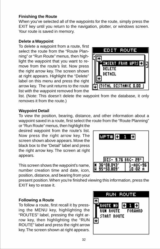
Finishing the RouteWhen you’ve selected all of the waypoints for the route, simply press theEXIT key until you return to the navigation, plotter, or windows screen.Your route is saved in memory.
Delete a WaypointTo delete a waypoint from a route, firstselect the route from the “Route Plan-ning” or “Run Route” menus, then high-light the waypoint that you want to re-move from the route’s list. Now pressthe right arrow key. The screen shownat right appears. Highlight the “Delete”label on this menu and press the rightarrow key. The unit returns to the routelist with the waypoint removed from thelist. (Note: This doesn’t delete the waypoint from the database, it onlyremoves it from the route.)
Waypoint DetailTo view the position, bearing, distance, and other information about awaypoint saved in a route, first select the route from the “Route Planning”or “Run Route” menus, then highlight thedesired waypoint from the route’s list.Now press the right arrow key. Thescreen shown above appears. Move theblack box to the “Detail” label and pressthe right arrow key. The screen at rightappears.
This screen shows the waypoint’s name,number creation time and date, icon,position, distance, and bearing from yourpresent position. When you’re finished viewing this information, press theEXIT key to erase it.
Following a RouteTo follow a route, first recall it by press-ing the MENU key, highlighting the“ROUTES” label, pressing the right ar-row key, then highlighting the “RUNROUTE” label and press the right arrowkey. The screen shown at right appears.

33
The black box is on the “Route # 1” label. If this isn’t the route you want touse, press the right or left arrow keys to switch to another one. Beforestarting the route, you’ll need to decide if you want to start at the begin-ning and travel forward or start at the last waypoint in the route and travelbackwards (reverse) to the first waypoint. The default is forward. Next,highlight the “Start Route” label and press the right arrow key. The screenshown below appears.
Once you determine which direction inthe route you want to go, you’ll need todetermine the first waypoint in the list youwant to start the route. Usually, it’s thefirst waypoint, however the Eagle Viewgives you several options. The defaultstarting waypoint is the first one in thelist. However, by pressing the right ar-row key, the word “AUTO” appears in the“Select First WPT” list. This starts theroute with the waypoint that’s closest to your present position. You canstart at any waypoint in the route. As you change the number, the se-lected starting waypoint is highlighted on the list.
If you want to see details about the highlighted waypoint, press the WPTkey.
When you have everything on this screenset as desired, press the ENT key to startthe Eagle View navigating to the firstwaypoint on the route.
As you travel to the first waypoint, theunit shows navigation data to the way-point. If you use the plotter, as shown atright, the unit draws a dotted line fromyour starting position (shown by the “S”),and a dashed line from the first waypoint to each of the other waypoints inthe route. When you enter the radius set by the arrival alarm, the EagleView automatically switches to the next waypoint on the list, showing navi-gation data to that waypoint, and so on until the last waypoint on the routelist has been reached. (Note: The arrival alarm does not have to be turnedon in order to use the route feature.)

34
Skip WaypointThe Eagle View lets you skip a waypointin a route without stopping the route. Todo this, first press the MENU key, thenhighlight the “Routes” menu and pressthe right arrow key, then highlight the“Skip WPT” label and press the right ar-row key. The unit returns to the naviga-tion, plotter, or windows screen with navi-gation data showing to the next waypointon the list.
Delete a RouteTo erase a route, first press the MENUkey, then highlight the “Routes” menuand press the right arrow key, highlightthe “Plan Route” label and press the rightarrow key. The screen shown at rightappears. Now select the route you wantto erase by pressing the right or left ar-row keys. When the desired route num-ber appears, then highlight the “DeleteRoute” label and press the right arrowkey. A message appears, asking if you really want to erase the route. Ifyou press the right arrow key, the route will be erased.

35
Navigating to a cursor locationThe Eagle View lets you navigation to alocation without storing it in the waypointdatabase by using the plotter and cur-sor. To do this, first switch to the plotterscreen. Now move the cursor to the lo-cation that you want to navigate to. Next,press the MENU key. A new menu ap-pears on the list: “Go To Cursor”. Pressthe right arrow key. The Eagle Viewshows nav data to the cursor location(shown as “D” on the plotter). See thescreen at the top of the next page.
NAVIGATION
Navigate To a WaypointThe Eagle View makes it easy to navi-gate to any waypoint. First, press theWPT key, then press the right or left ar-row keys until the desired waypoint ap-pears. Now highlight the “Go To WPT#”label and press the right arrow key. Theunit immediately returns to the naviga-tion, plotter, or windows screen andshows navigation information to the se-lected location.
In this example, we recalled waypointnumber 2. Switching to a plotter screen(shown at the top of the next page)shows our starting location “S”, the re-called waypoint “2”, and our present po-sition.

36
Navigating to a Waypoint using thePlotterThe unique “birds-eye” view used by theplotter gives you an easy way to navi-gate to a waypoint. On the screen shownat right, the diamond with a cross in it isyour present position. The box with the“S” in it was your starting location whenyou recalled the waypoint. The dotted line is called a track line and is theshortest path from the starting location to the destination. The “D” is thecursor destination, the number with a box around it is the waypoint. If youfollow the track line, you’ll reach the destination, covering the shortestdistance in the least time.
CAUTION!The Eagle View does NOT take land features, altitudes, restricted orprohibited areas, or any other feature into account when it projects thetrack line on the screen. Therefore, you must use care when navigatingon the track line and avoid any object that may be in your path to thedestination.
CANCEL NAVIGATIONThe Eagle View continues to navigate to a recalled waypoint, the lastwaypoint in a route, or the cursor posi-tion until you stop it.
To stop the navigation function, press theMENU key, then press the up or downarrow keys until the “Cancel Naviga-tion” label is highlighted. Press the rightarrow key. The unit stops showing navi-gation information.

37
SYSTEM SETUPThe Eagle View has several menus andcommands listed under the “SystemSetup” label on the main menu. Thesecommands affect the basic operation ofthe unit. To use them, press the MENUkey, then highlight the “System Setup”label. Press the right arrow key. Thescreen shown at right appears.
SPEAKERYou can turn the speaker off. Turning the speaker off also turns off theaudible portion of the alarms.
To turn the speaker off, highlight the “Sound” label on the “System Setup”menu as shown above. Now press the left arrow key to turn the speakeroff. Repeat these steps to turn the speaker on. Press the EXIT key toerase this screen.
CONTRASTTo adjust the display’s contrast, highlight the “Cont” label on the “SystemSetup” menu as shown above. Press the right or left arrow keys until thescreen’s contrast is best for the lighting conditions. Press the EXIT key toerase this screen.
Units of MeasureThe Eagle View can show its data in many different formats. For example,distance can be displayed in statute miles (MI), nautical miles (NM), orkilometers (KM).
The following can be changed on the Units of Measure menu: (Defaultsshown in bold )
Distance .................. miles , nautical miles, kilometersSpeed...................... miles per hour , knots, kilometers per hourBearing.................... magnetic , trueAltitude .................... feet , metersClock ....................... 12-hour (a.m.-p.m.) , 24 hourPosition Format ....... degrees, minutes, and thousands of a minute
degrees, minutes, secondsUTMstandard military grid reference systemalternate military grid reference system

38
To change a unit of measure, first selectthe “Set Units” from the “System Setup”menu. The screen shown at right ap-pears. Highlight the desired selection,then press the left or right arrow key. Youcan change one or all of the settings onthis page. When you’re finished, pressthe EXIT key.
Position FormatTo change the position format, highlightthe “Position Format” label on the Unitsof Measure menu, (shown above) thenpress the right arrow key. A screen simi-lar to the one at right appears.
The Eagle View can show the positionin degrees, minutes, and thousandthsof a minute (36 28.700') or degrees, min-utes, seconds, and tenths of a second(36 28' 40.9". It can also show position in UTM’s (Universal TransverseMercator) projection, British, Irish, and Military Grid systems.
UTM’s are marked on USGS topo-graphic charts. This system divides theEarth into 60 zones, each approximately6 degrees wide in longitude. Their unitof measure is in meters. For example,30 N means that the position shown tothe left of the “N” is in grid 30, and it’snorth of the equator.
British and Irish grid systems are thenational coordinate system used only intheir respective countries.
Note: In order to use either the British orIrish grid systems, you must be in theU.K.

39
NMEA / DGPSThe Eagle View transmits data through the data port in the back of theunit using NMEA 0183 format, version 1.5 or 2.0. This data is used byother electronic devices such as marine autopilots for position and steer-ing information.
DGPS on the other hand, is a data input. DGPS is an acronym for Differ-ential Global Positioning System. Currently, it relies on a system of ground-based transmitters that send correction signals to small DGPS receivers.DGPS gives you more accurate positions than is otherwise possible.
The Eagle View can use the military gridreference system (MGRS). It uses twogrid lettering schemes, which are re-ferred to as standard and alternateMGRS on the View. Your position anddatum in use determines which one touse. In general, if the datum you’re us-ing is valid for your present position, thenuse the standard MGRS, otherwise usethe alternate MGRS.
Press the up or down arrow keys to high-light the desired position format. Pressthe EXIT key to both select the formatand erase the position format menu.

40
All wiring connections to the Eagle View are made to it’s power cable. Seethe sample wiring diagrams on the next page for general wiring proce-dures. Read your other product’s owner’s manual for more wiring informa-tion.
Once the cables are wired, turn theEagle View on, press the menu key, andselect NMEA / DGPS from the SystemSetup menu. A screen similar to the oneat right appears.
NMEA OUTPUTTo turn the NMEA output on, highlightthe “NMEA OUTPUT” menu, then pressthe right arrow key. If your other equip-ment works, then no setup will need to be performed. If your other equip-ment doesn’t recognize the NMEA data being sent by the Eagle View andthe wiring is correct, then you may need to change the NMEA or the serialcommunication settings.
Configure NMEA OutputHighlight the “Configure NMEA Output”menu, then press the right arrow key. Ascreen similar to the one at right appears.
NMEA 0183 VersionThere are two versions of the NMEAdata, 1.5 and 2.0. If your other equip-ment requires 2.0, press the right arrowkey to select it.
RMC/RMB, GLL, APB, GGA, GSA/GSV SentencesSome equipment requires different sentence. The Eagle View’s defaultsetting for these sentences is on. In other words, it automatically sendsthese sentences when NMEA is turned on. To turn any of these off, movethe black box to the desired menu and press the left arrow key. Press theEXIT key when everything on this screen is the way you want it.
DGPSThe Eagle View will recognize Starlink® and Magnavox® automatic DGPSreceivers. If you have either one of these receivers, simply highlight the“Starlink DGPS” or “Magnavox DGPS” on the NMEA / DGPS menu andpress the right arrow key to turn it on. (Note: If you have a MagnavoxDGPS receiver connected, the Eagle View can’t send NMEA data.) With

41
TO EAGLE VIEW
OTHERDEVICE
12 VDCBATTERY
BLACK WIRE
GROUND WIRES
WHITE WIRERED WIRE
TO +12V
OTHERDEVICE’SRECEIVE
DATA WIRE
EAGLE VIEW’SWIRES
OTHER DEVICE’SWIRES
EAGLE VIEW TRANSMIT-TING NMEA DATA TOANOTHER DEVICE
TO EAGLE VIEW
DGPSRECEIVER
12 VDCBATTERY
BLACK WIRE
GROUND WIRES
WHITE WIRERED WIRE
TO +12V
DGPSRECEIVER’S
RECEIVEDATA WIRE
(IF NEEDED)
EAGLE VIEW’SWIRES
EAGLE VIEW RECEIV-ING DATA FROM A DGPS
RECEIVER
GREEN WIRE
DGPSRECEIVER’STRANSMITDATA WIRE

42
the exception of serial communications, typically no other setup needs tobe made with these receivers.
If you have any other Magnavox orStarlink compatible DGPS receiver con-nected to the Eagle View, you may needto change the settings. To do this, movethe black box to the “Configure DGPSBeacon Receiver” label and press theright arrow key. A screen similar to theone at right appears.
These menus select the beaconreceiver’s frequency and bit rate (in bits per second). If you are using aStarlink receiver, turning the auto mode on causes the Eagle View toauto-detect the frequency and bit rate.
To change one of these settings, simply highlight the menu item you wishto change, then press the right or left arrow key until the desired numberappears. Press the EXIT key when you’re finished.
SERIAL COMMUNICATIONS SETUPTo set the data port, move the black boxto the “Setup Com” on the System Setupmenu. Press the right arrow key. Thescreen shown at right appears.
Check your DGPS receiver’s manual forthe proper data settings. Highlight themenu item you need to change. Pressthe left or right arrow keys to changethem. The serial port defaults are 4800baud, no parity, and 8 data bits. Press the EXIT key to erase this menu.
RESET OPTIONSTo return the Eagle View to its originalfactory settings, highlight the “Preset Op-tions” menu on the System Setup screen.Now press the right arrow key. A mes-sage appears, asking if you want to re-store the original options. Press the rightarrow key if you do, the left arrow key toquit.

43
If you restore the unit to the factory settings, all options such as contrast,alarms, and other system choices are returned to their default values.However, no waypoints, routes, or icons are erased.
RESET GROUPSTo return all groups to their factory defaults, highlight the “RESETGROUPS” label on the “System Setup” menu. Finally, press the rightarrow key. All digital boxes on the navigation plotter screens are reset totheir factory settings.
SYSTEM INFOThe system information screen showsthe release date and the version num-ber of the code stored inside the EagleView. To view this screen, highlight the“System Info” label on the “SystemSetup” menu. Now press the right arrowkey. A screen similar to the one at rightappears. Press the EXIT key when you’refinished reading this screen.
GPS SETUPThe GPS Setup menu has sub-menusthat affect the GPS receiver. From thesemenus you can turn the simulator on oroff, set the update rate, initialize the GPSreceiver, do a self-test on the receiver,and do a cold-start. (Note: The “InitializeGPS receiver” is covered in the “FindingYour Position” section in the front of thismanual.
To view these menu items, press the MENU key, then highlight the “GPSSetup” menu. Press the right arrow key. The screen shown above ap-pears.
Execute GPS Cold StartWhen the Eagle View is turned on for the first time “out of the box”, itautomatically sends a “cold-start” message to the GPS receiver. You canalso send a cold start message to the receiver at any time.
If the unit can’t lock on to the satellites using the data you’ve given it, or ifit has trouble finding the satellites, perhaps it is using the wrong data. Thiscan happen if you’ve entered the wrong data by accident when initializing

44
the receiver. For example, if you enteredeast longitude instead of west. Or ifyou’ve moved a long distance with theunit turned off.
To send a cold start message to the re-ceiver, highlight the “Execute GPS ColdStart” label, then press the right arrowkey. A message appears, asking you ifyou really want to do a cold start. Followthe instructions on this message page.
The unit will begin searching for the satellites. It can take as long as 5minutes for it to lock on to the necessary satellites. Remember, when itdoes, your local time and possibly date can be wrong. Use the methodshown in the initialization section at the front of this manual to changethem, if needed. Once this is done, an internal clock will keep the correcttime, even when the unit is turned off. The GPS system updates this clockwhen the unit is locked on to the satellites.
DATUMMaps and charts are based on a survey of the area that’s covered by themap or chart. These surveys are called “Datums”. Maps that are createdusing different datums will show the same latitude/longitude in slightlydifferent locations.
All datums are named. The GPS system is based on the WGS-84 datum,which covers the entire world. Other datums may also cover the entireworld, or just a small portion. By default, the Eagle View shows your posi-tion on the map using the WGS-84 datum. However, it can show yourposition using one of 189 different da-tums.
To change the datum, first press theMENU key, then highlight the “GPSSetup” label and press the right arrowkey. Now highlight the “Select Datum”label. Finally, press the right arrow keyagain. A screen similar to the one at rightappears.
The WGS-84 label is highlighted. To change it, simply press the up ordown arrow keys to highlight the desired datum, then press the ENT key.This selects the datum and erases the select datum menu.

45
PCF (Position Correction Factor)Another method used to make your display match a chart or map is called“PCF” or Position Correction Factor. This unit gives you the capability tomove or offset the position shown on the display to match one on thechart. The unit will add this offset to all position and navigation displays atall times.
Remember, the position error on any radio navigation system is very dy-namic and the PCF offset should never be used in an attempt to cancelthe error.
In general terms, PCF should only be used if your map indicates what thepossible error is. PCF should always be reset to zero when you’refinished with the chart.
For example, suppose you are stopped at a location that is accuratelymarked on a chart. Your unit shows a longitude position that is .244 min-utes east of the one on the chart and .047 minutes north latitude. Usingthe PCF feature, you can make the Eagle View match the chart you’reusing. If you move, the unit will continuously add the change to all posi-tion, navigation, and mapping displays. This makes it more closely matchthe datum used by the chart. For this reason, you should be careful whenentering the PCF offset. It’s saved in memory and doesn’t change whenthe unit is turned off. However, resettingthe unit does erase the PCF offset.
To change the PCF offset, first press theMENU key, then highlight the “GPSSetup” label and press the right arrowkey. Now highlight the “Set PCF Offset”label. Finally, press the right arrow keyagain. A screen similar to the one at rightappears.
Now enter the correction for your loca-tion. Remember, this is the differencebetween the location shown on thepresent position display and the positionshown on the chart. In this example, weentered 0 degrees, 0.047 minutes northlatitude and 0 degrees, 0.244 minuteseast longitude. That is the difference be-tween the present position shown by theEagle View and the one on our chart.

46
After you’ve entered the latitude/longitude correction, press the ENT keyto accept it. The Eagle View erases the PCF entry screen and returns tothe navigation or mapping screens with the correction factor applied.
POSITION PININGWhen using a GPS receiver at extremely low speeds, it can have troubledetermining your course over ground, or direction you’re travelling. This isdue in large part to SA, or selective availability. SA is small inaccuraciespurposefully put into the GPS satellite’s signal by the government. Thiscause wide variations in the track display and other navigation displayswhen using the unit at slow speeds.
If you’re using the Eagle View without DGPS and stop, the position pin-ning feature locks the present position indicator on the plotter until you’vemoved a short distance or exceed a very slow speed. This prevents the“wandering” plot trail seen when you’re stopped with position pinning turnedoff. This also affects the navigational displays.
The easiest way to see the effects of S/A is to stand still with the EagleView turned on and watch your plot trail with position pinning turned off.You’ll see the present position change, speed increase and decrease,and a random plot trail on the plotter’s screen.
To turn the position pining feature off, press the MENU key, then highlightthe “GPS Setup” label and press the right arrow key. Now highlight the“Pos Pinning” label. Finally, press the left arrow key.
ALARMSThe Eagle View has several alarms. You can set an arrival alarm to sounda warning tone when you cross a preset distance from a waypoint. Forexample, if you have the arrival alarm set to .1 mile, then the alarm willsound when you come within .1 mile of the recalled waypoint. The coursedeviation indicator alarm (CDI) can sound a warning when your track driftstoo far to the right or left of the line to the waypoint. For example, if thealarm is set to .1 mile, then the alarm will sound if you drift .1 of a mile ormore to the right or left of the line to thewaypoint. The anchor alarm sounds awarning when you drift outside of a pre-set radius. Again, using the .1 mile as anexample, if you’re anchored and yourboat moves more than .1 of a mile, thealarm will sound.

47
To use any of these alarms, first press the MENU key, then select the“ALARMS/CDI” menu. A screen similar to the one shown at right appears.Press the up or down arrow key to move the black box to the desiredalarm, then press the right arrow key to turn it on.To adjust an alarm’s distance, move the black box to the alarm’s “DIST”menu item, then press the right or left arrow keys to increase or decreasethe alarm’s distance.
When you’re finished adjusting the alarms, press the EXIT key to erasethis menu.
Important Alarm Notes:Anchor Alarm - Since civilian users don’t receive the accuracy given tomilitary users, the anchor alarm may sound even when you’re sittingstill. This typically happens when using small (less than .05 mile) an-chor alarm ranges. If you have a DGPS beacon receiver connected tothe Eagle View, smaller ranges may be usable.
Arrival Alarm - If you set the arrival alarm’s distance to zero (0), and yourun a route (see the routes section), the Eagle View may not show navi-gation data to the next waypoint, once you arrive at the first one. If you usethe routes feature, never set the arrival alarm to zero.
MESSAGESOn the GPS Alarms menu are the position and DGPS message selec-tions. When turned on, the position message appears for a few secondswhenever the Eagle View locks onto the satellites and shows a position. Italso appears when the unit loses the lock onto the satellites and cannotnavigate. Pressing the EXIT key erases these messages.
The DGPS message appears whenever the unit begins or stops usingDGPS data to help determine your position.
The default setting for these messages is “on”. To turn either message off,select the “GPS Alarms” menu from the main menu, then move the blackbox to the desired message and press the left arrow key. Press the EXITkey to erase this screen.
BACKLIGHTThe AirMap’s display and keyboard have lights that can be turned on fornight use. To turn the lights on, simply press the PWR key. To turn themoff, press the PWR key again.

48
SIMULATORA simulator is built into the Eagle View that has several options. You canuse nearly all of the unit’s features - even save and recall waypoints. Thisis useful for trip planning.
To use the simulator, press the MENUkey, then press the up or down arrowkeys until the “Simulator Setup” menu issurrounded by the black box. Now pressthe right arrow key. The screen shown atright appears.
If you simply press the right arrow key,turning the simulator on, the Eagle Viewwill start from your present position and follow a track of 355° at 100 milesper hour.
To change either the track or speed, highlight the one you want to change,then press the right or left arrow key. When the numbers are correct,press the EXIT key.
Starting PositionNormally, the starting position for thesimulator is your present position. If youwant to change the starting position,highlight the “Set Starting Waypoint” la-bel on the Simulator Setup menu, thenpress the right arrow key. The screenshown at right appears.
You can select any waypoint as thesimulator’s starting point. Select the starting point by pressing the rightarrow key on the “WPT#” label until the desired starting waypoint numberappears. Now highlight the “Start At” label and press the right arrow key.The Eagle View returns to the Simulator Setup menu.
Use Arrow Keys to SteerThis option lets you change both thecourse and speed on the screen as thesimulator is running. To do this, highlightthe “User Arrows to Steer” label on theSimulator Setup screen, then press theright arrow key. The screen shown at rightappears. Use the up and down arrow keys
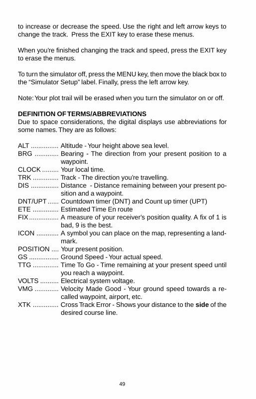
49
to increase or decrease the speed. Use the right and left arrow keys tochange the track. Press the EXIT key to erase these menus.
When you’re finished changing the track and speed, press the EXIT keyto erase the menus.
To turn the simulator off, press the MENU key, then move the black box tothe “Simulator Setup” label. Finally, press the left arrow key.
Note: Your plot trail will be erased when you turn the simulator on or off.
DEFINITION OF TERMS/ABBREVIATIONSDue to space considerations, the digital displays use abbreviations forsome names. They are as follows:
ALT ............... Altitude - Your height above sea level.BRG ............. Bearing - The direction from your present position to a
waypoint.CLOCK ......... Your local time.TRK .............. Track - The direction you’re travelling.DIS ............... Distance - Distance remaining between your present po-
sition and a waypoint.DNT/UPT ...... Countdown timer (DNT) and Count up timer (UPT)ETE .............. Estimated Time En routeFIX ................ A measure of your receiver’s position quality. A fix of 1 is
bad, 9 is the best.ICON ............ A symbol you can place on the map, representing a land-
mark.POSITION .... Your present position.GS ................ Ground Speed - Your actual speed.TTG .............. Time To Go - Time remaining at your present speed until
you reach a waypoint.VOLTS .......... Electrical system voltage.VMG ............. Velocity Made Good - Your ground speed towards a re-
called waypoint, airport, etc.XTK .............. Cross Track Error - Shows your distance to the side of the
desired course line.

50
WINDOWSThe following is a listing of windows groups A through O.
GROUP “A” GROUP “B”
GROUP “C” GROUP “D”
GROUP “E” GROUP “F”
GROUP “G” GROUP “H”
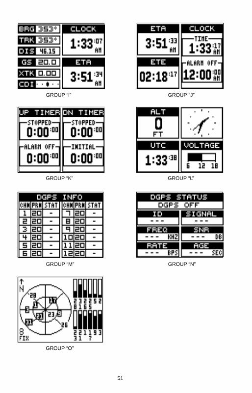
51
GROUP “I” GROUP “J”
GROUP “K” GROUP “L”
GROUP “M” GROUP “N”
GROUP “O”

52
Eagle's UPS Return Service - U.S.A. OnlyEagle Electronics and United Parcel Service (UPS) are proud to offer allof our customers free shipping for all units sent to us for repair or service.If you have to send this unit to the factory, and you are in the continentalUnited States, use the enclosed UPS shipping label for easy, free ship-ping to our factory customer service department. There are six easysteps:
1. Call Eagle at the toll-free number on the back of this manual for aReturn Authorization (RA) number and instructions about what acces-sories to return. Do not return a product to the factory without aReturn Authorization (RA) Number!
2. Pack your unit and any accessories in the original shipping container,if possible. Be sure to include proof of purchase for warranty veri-fication!
3. Write a brief note detailing the problem you're having with the unit.Please include your name, address, and daytime telephone number.
4. Please include payment for non-warranty repairs. Check, money order,Visa, or MasterCard may be used.
5. Fill in your name, address, zip code, date, and RA number in the blanksprovided on the UPS form included with your unit.
6. Attach the label to the shipping box, tear off the tab for your receiptand give the package to any UPS driver or take the package to anyUPS Customer Center. You will not be charged for this shipment.
That's it! Your unit will be shipped to Eagle's customer service departmentat no charge to you. Units under warranty will be returned to you at nocharge.
NOTE!Eagle will pay UPS surface shipping charges both to and from the factoryfor this unit in the event it needs repair. Your unit is insured against loss orshipping damage when you use the enclosed UPS label.
This UPS shipping offer is good only in the continental United States (ex-cludes Alaska and Hawaii).

53
KEEP THIS LABEL!YOU WILL NEED IT IF YOU EVER NEED TO RETURN YOUR UNIT TO
THE FACTORY FOR REPAIR.
Accessory Ordering InformationTo order accessories such as power cables, please contact:
1) Your local marine dealer. Most quality dealers that handle marine elec-tronic equipment should be able to assist you with these items. Consultyour local telephone directory for listings.
2) LEI Extras, Inc. P.O. Box 129 Catoosa, OK 74015-0129or call
800-324-0045(USA orders only.)
Eagle Electronics may find it necessary to change or end our shippingpolicies, regulations, and special offers at any time. We reserve the rightto do so without notice.

54
EAGLE ELECTRONICSFULL ONE-YEAR WARRANTY
“We", “our”, or “us” refers to EAGLE ELECTRONICS, a division of LEI, the manufacturer ofthis product. “You” or “your” refers to the first person who purchases this product as aconsumer item for personal, family, or household use.
We warrant this product against defects or malfunctions in materials and workmanship,and against failure to conform to this product’s written specifications, all for one year (1)from the date of original purchase by you. WE MAKE NO OTHER EXPRESS WARRANTYOR REPRESENTATION OF ANY KIND WHATSOEVER CONCERNING THIS PRODUCT.Your remedies under this warranty will be available so long as you can show in a reason-able manner that any defect or malfunction in materials or workmanship, or any non-conformity with the product’s written specifications, occurred within one year from the dateof your original purchase, which must be substantiated by a dated sales receipt or salesslip. Any such defect, malfunction, or non-conformity which occurs within one year fromyour original purchase date will either be repaired without charge or be replaced with anew product identical or reasonably equivalent to this product, at our option, within a rea-sonable time after our receipt of the product. If such defect, malfunction, or non-conformityremains after a reasonable number of attempts to repair by us, you may elect to obtainwithout charge a replacement of the product or a refund for the product. THIS REPAIR,REPLACEMENT, OR REFUND (AS JUST DESCRIBED) IS THE EXCLUSIVE REMEDYAVAILABLE TO YOU AGAINST US FOR ANY DEFECT, MALFUNCTION, OR NON-CON-FORMITY CONCERNING THE PRODUCT OR FOR ANY LOSS OR DAMAGE RESULT-ING FROM ANY OTHER CAUSE WHATSOEVER. WE WILL NOT UNDER ANY CIR-CUMSTANCES BE LIABLE TO ANYONE FOR ANY SPECIAL, CONSEQUENTIAL, INCI-DENTAL, OR OTHER INDIRECT DAMAGE OF ANY KIND.
Some states do not allow the exclusion or limitation of incidental or consequential dam-ages, so the above limitations or exclusions may not apply to you.
This warranty does NOT apply in the following circumstances: (1) when the product hasbeen serviced or repaired by anyone other than us, (2) when the product has been con-nected, installed, combined, altered, adjusted, or handled in a manner other than accord-ing to the instructions furnished with the product, (3) when any serial number has beeneffaced, altered, or removed, or (4) when any defect, problem, loss, or damage has re-sulted from any accident, misuse, negligence, or carelessness, or from any failure to pro-vide reasonable and necessary maintenance in accordance with the instructions of theowner’s manual for the product.
We reserve the right to make changes or improvements in our products from time to timewithout incurring the obligation to install such improvements or changes on equipment oritems previously manufactured.
This warranty gives you specific legal rights and you may also have other rights which mayvary from state to state.
REMINDER: You must retain the sales slip or sales receipt proving the date of your origi-nal purchase in case warranty service is ever required.
EAGLE ELECTRONICSPO BOX 669 CATOOSA, OK 74015
(800) 324-1354

55
ANTENNA MODULE TEMPLATE
25MM (1”)(If Necessary)
4.75MM (3/16”)4 PLACES

56
THIS PAGE INTENTIONALLY LEFT BLANK

57
How to Obtain Service(Canadian Customers Only)We back your investment in quality products with quick, expert service and genuineEagle replacement parts. If you need service or repairs, contact the Eagle FactoryCustomer Service Department at the toll-free number listed below. A technician may beable to solve the problem and save you the inconvenience of returning your unit. You willbe asked for your unit's serial number.
800-324-1354Canada Only. Monday through Friday 8:00 A.M. - 8:00 P.M. Central Time.
When sending a product for repair, please do the following:1. Always use the original shipping container and filler material the product was packed
in when shipping your product.
2 Always insure the parcel against damage or loss during shipment. Eagle does notassume responsibility for goods lost or damaged in transit.
3. For proper testing, repair, and service, send a brief note with the product describingthe problem. Be sure to include your name, return shipping address, and a daytimetelephone number.
How to Obtain Service(International Customers Only - Except Canada)
If you need service or repairs, contact the dealer in the country you purchased yourunit.
WARRANTY REPAIR WILL BE HONORED ONLY IN THECOUNTRY UNIT WAS PURCHASED.
Please follow the shipping instructions shown below on this page if you have to mailyour unit to the dealer. For proper testing, repair, and service, send a brief note with theproduct describing the problem. Be sure to include your name, return shipping ad-dress, and a daytime telephone number.
Accessory Ordering Information - All CountriesTo order accessories such as power cables or transducers, please contact:1. Your local dealer. Most quality dealers that handle GPS navigation equipment
should be able to assist you with these items. Consult your local telephone direc-tory for listings.
2. Canadian customers only can write:Eagle/Eagle Canada, 919 Matheson Blvd., E. Mississauga, Ontario L4W2R7
or fax 416-629-3118

58
How to Obtain Service - U.S.A. OnlyWe back your investment in quality products with quick, expert serviceand genuine Eagle™ replacement parts. If you're in the United Statesand you have questions, please contact the Factory Customer ServiceDepartment using our toll-free number listed below. You must send theunit to the factory for warranty service or repair. Please call the factorybefore sending the unit. You will be asked for your unit's serial number(shown above). Use the following toll-free number:
800-324-1354U.S.A.only. Monday through Friday 8:00 A.M. - 8:00 P.M. Central time, except holidays.
Your unit is covered by a full one-year warranty. (See page 54 inside thismanual for complete warranty details.) If your unit fails and the failure isnot covered by the original warranty, Eagle has a flat-rate repair policythat covers your unit and accessories packed with the unit at the factory.There is a 180-day warranty on all non-warranty repairs from the factory,which is similar to the original warranty, but is for 180 days rather than oneyear. For further details, please call us at the above number.
Eagle also gives you free UPS shipping from anywhere in the continentalUnited States both to and from the factory for all warranty repairs. You canalso use the enclosed UPS shipping label for non-warranty shipments.See page 52 for more information. Remember, non-warranty repairs aresubject to Eagle's published flat-rate charges and 180-day warranty.
LITHO IN U.S.A. 988-0129-77