Embed Size (px)
Citation preview

Department of Mechanical Engineering Prepared By: Paras G. Vegada Darshan Institute of Engineering & Technology, Rajkot Page 1.1
1 MANUFACTURING PROCESSES
Course Contents
1.1 Introduction
1.2 Importance of Manufacturing
1.3 Classification of manufacturing
process

1. Introduction Manufacturing Processes II (2141908)
Prepared By: Paras G. Vegada Department of Mechanical Engineering Page 1.2 Darshan Institute of Engineering & Technology, Rajkot
1.1 Introduction
Manufacturing is the backbone of any industrialized nation.
Manufacturing and technical staff in industry must know the various manufacturing
processes, materials being processed, tools and equipments for manufacturing different
components or products with optimal process plan using proper precautions and
specified safety rules to avoid accidents.
Beside above, all kinds of the future engineers must know the basic requirements of
workshop activities in term of man, machine, material, methods, money and other
infrastructure facilities needed to be positioned properly for optimal shop layouts or
plant layout and other support services effectively adjusted or located in the industry or
plant within a well-planned manufacturing organization.
1.2 Importance of Manufacturing process
Manufacturing is achieved through a proper planning and control system.
It is classified as continuous production and intermittent production.
Continuous production involves a continuous flow of material physically, leading to large
quantities of finished good.
Chemical processing, cigarette manufacturing and cement manufacturing are some of
the industries employing continuous production.
Also, sheets, wires, pipes, TV sets, motor cycles are examples of continuous production.
An intermitted production involves interrupted flow of material through the plant.
Machine shops, welding shops, etc. are industries employing intermittent production.
Importance of manufacturing towards technology development
Manufacturing and technology are complementary to each other
Growth in manufacturing enables increase availability of finish goods and its appliance in
various sectors.
Such appliance leads to technology development of the industries which is then
transferred to development of manufacturing technology.
Growth of manufacturing is also referred to as an index of technology growth of a
country
Manufacturing provides availability of finish goods for technology application.
Importance of manufacturing towards social-economic development.
Manufacturing is backbone of any economy.
Manufacturing industries provides employment to hundreds of people.
Before the industrial revolution, manufacturing was carried out in rural area, where
household-based manufacturing was the trend.
Later government policy and entrepreneurs organized a number of manufacturing house
hold in to a single enterprise producing goods at large scale.
It leads to development of industrialization and society.
Manufacturing provides an opportunity for establishment of allied industries.

Manufacturing Processes (2141908) 1. Introduction
Department of Mechanical Engineering Prepared By: Paras G. Vegada Darshan Institute of Engineering & Technology, Rajkot Page 1.3
It provides a boost to the services industry catering to the people employed.
Manufacturing is considered as a wealth-producing sector of an economy.
It provides important material supports for national infrastructure and for national
defense.
1.3 Classification of Manufacturing Process
For producing of products materials are needed. It is therefore important to know the
characteristics of the available engineering materials.
Raw materials used manufacturing of products, tools, machines and equipments in
factories or industries are extracted from ores.
The ores are suitably converted the metal into a molten form by reducing or refining
processes in foundries.
This molten metal is poured into moulds for providing commercial castings, called ingots.
Such ingots are then processed in rolling mills to obtain market form of material supply
in form of bloom, billets, slabs and rods.
These forms of material supply are further subjected to various manufacturing processes
for getting usable metal products of different shapes and sizes in various manufacturing
shops.
All these processes used in manufacturing concern for changing the ingots into usable
products may be classified into six major groups as primary shaping processes,
secondary machining processes, metal forming processes, joining processes, surface
finishing processes and processes effecting change in properties. These are discussed as
under.
1. Primary Shaping Processes
Primary shaping processes are manufacturing of a product from an amorphous material.
Some processes produces finish products or articles into its usual form whereas others
do not, and require further working to finish component to the desired shape and size.
Castings need re-melting of scrap and defective ingots in cupola or in some other
melting furnace and then pouring of the molten metal into sand or metallic moulds to
obtain the castings. Thus the intricate shapes can be manufactured.
Typical examples of the products that are produced by casting process are machine
beds, automobile engines, carburetors, flywheels etc. The parts produced through these
processes may or may not require to under go further operations.
Some of the important primary shaping processes is:
(1) Casting, (2) Powder metallurgy, (3) Plastic technology, (4) Gas cutting, (5) Bending
and (6) Forging.
1. Introduction Manufacturing Processes II (2141908)
Prepared By: Paras G. Vegada Department of Mechanical Engineering Page 1.4 Darshan Institute of Engineering & Technology, Rajkot
2. Secondary or Machining Processes
As large number of components require further processing after the primary processes.
These components are subjected to one or more number of machining operations in
machine shops, to obtain the desired shape and dimensional accuracy on flat and
cylindrical jobs. Thus, the jobs undergoing these operations are the roughly finished
products received through primary shaping processes.
The process of removing the undesired or unwanted material from the workpiece or job
or component to produce a required shape using a cutting tool is known as machining.
This can be done by a manual process or by using a machine called machine tool
(traditional machines namely lathe, milling machine, drilling, shaper, planner, slotter).
In many cases these operations are performed on rods, bars and flat surfaces in machine
shops. These secondary processes are mainly required for achieving dimensional
accuracy and a very high degree of surface finish. The secondary processes require the
use of one or more machine tools, various single or multi-point cutting tools (cutters),
job holding devices, marking and measuring instruments, testing devices and gauges etc.
for getting desired dimensional control and required degree of surface finish on the
workpiece.
The example of parts produced by machining processes includes hand tools machine
tools instruments, automobile parts, nuts, bolts and gears etc. Lot of material is wasted
as scrap in the secondary or machining process. Some of the common secondary or
machining processes are—
(1) Turning, (2) Threading, (3) Knurling, (4) Milling, (5) Drilling, (6) Boring, (7) Planning,
(8) Shaping, (9) Slotting, (10) Sawing, (11) Broaching, (12) Hobbing, (13) Grinding, (14)
Gear cutting, (15) Thread cutting and (16) Unconventional machining processes namely
machining with Numerical Control (NC) machines tools or Computer Numerical Control
(CNC) machines tools using ECM, LBM, AJM, USM setups etc.
3. Metal Forming Processes
Forming processes encompasses a wide variety of techniques, which make use of
suitable force, pressure or stresses, like compression, tension and shear or their
combination to cause a permanent deformation of the raw material to impart required
shape. These processes are also known as mechanical working processes and are mainly
classified into two major categories i.e., hot working processes and cold working
processes. In these processes, no material is removed; however it is deformed and
displaced using suitable stresses like compression, tension, and shear or combined
stresses to cause plastic deformation of the materials to produce required shapes. Such
processes lead to production of directly usable articles which include kitchen utensils,
rods, wires, rails, cold drink bottle caps, collapsible tubes etc. Some of the important
metals forming processes are:

Manufacturing Processes (2141908) 1. Introduction
Department of Mechanical Engineering Prepared By: Paras G. Vegada Darshan Institute of Engineering & Technology, Rajkot Page 1.5
Hot working Processes
(1) Forging, (2) Rolling, (3) Hot spinning, (4) Extrusion, (5) Hot drawing and (6) Hot
spinning.
Cold working processes
(1) Cold forging, (2) Cold rolling, (3) Cold heading, (4) Cold drawing, (5) Wire drawing,
(6) Stretch forming, (7) Sheet metal working processes such as piercing, punching,
lancing, notching, coining, squeezing, deep drawing, bending etc.
4. Joining Processes
These processes are used for assembling metal parts and in general fabrication work.
Such requirements usually occur when several pieces are to be joined together to
fabricate a desired structure of products.
These processes are used developing steam or water-tight joints. Temporary, semi-
permanent or permanent type of fastening to make a good joint is generally created by
these processes.
Temporary joining of component scan be achieved by use of nuts, screws and bolts.
Adhesives are also used to make temporary joints. Some of the important and common
joining processes are:
(1) Welding (plastic or fusion), (2) Brazing, (3) Soldering, (4) Riveting, (5) Screwing, (6)
Press fitting, (7) Sintering, (8) Adhesive bonding, (9) Shrink fitting, (10) Explosive welding,
(11) Diffusion welding, (12) Keys and cotters joints, (13) Coupling and (14) Nut and bolt
joints.
5. Surface Finishing Processes
Surface finishing processes are utilized for imparting intended surface finish on the
surface of a job.
By imparting a surface finishing process, dimension of part is not changed functionally;
either a very negligible amount of material is removed from the certain material is added
to the surface of the job.
These processes should not be misunderstood as metal removing processes in any case
as they are primarily intended to provide a good surface finish or a decorative or
protective coating on to the metal surface.
Surface cleaning process also called as a surface finishing process. Some of the
commonly used surface finishing processes are:
(1) Honing, (2) Lapping, (3) Super finishing, (4) Belt grinding, (5) Polishing, (6) Tumbling,
(7) Organic finishes, (8) Sanding, (9) deburring, (10) Electroplating, (11) Buffing, (12)
Metal spraying, (13) Painting, (14) Inorganic coating, (15) Anodizing, (16) Sheradising,
(17) Parkerizing, (18) Galvanizing, (19) Plastic coating, (20) Metallic coating, (21)
Anodizing and (22) Sand blasting.
6. Processes Effecting Change in Properties
Processes effecting change in properties are generally employed to provide certain
specific properties to the metal work pieces for making them suitable for particular
operations or use.
1. Introduction Manufacturing Processes II (2141908)
Prepared By: Paras G. Vegada Department of Mechanical Engineering Page 1.6 Darshan Institute of Engineering & Technology, Rajkot
Some important material properties like hardening, softening and grain refinement are
needed to jobs and hence are imparted by heat treatment. Heat treatments affect the
physical properties and also make a marked change in the internal structure of the
metal.
Similarly the metal forming processes effect on the physical properties of work pieces
similarly shot peening process, imparts fatigue resistance to work pieces. A few such
commonly used processes are given as under:
(1) Annealing, (2) Normalising, (3) Hardening, (4) Case hardening, (5) Flame hardening,
(6) Tempering, (7) Shot peeing, (8) Grain refining and (9) Age hardening.
In addition, some allied manufacturing activities are also required to produce the
finished product such as measurement and assembly.

Department of Mechanical Engineering Prepared By: Paras G. Vegada Darshan Institute of Engineering & Technology, Rajkot Page 2.1
2 Metal Casting Processes
Course Contents
2.1 Introduction 2.2 Advantages and Applications of
Metal Casting 2.3 Pattern Making 2.4 Pattern Materials 2.5 Pattern Allowances 2.6 Types of Patterns 2.7 Pattern Colours 2.8 Mould Materials 2.9 Sand Preparation and Conditioning 2.10 Sand Testing 2.11 Core 2.12 Types of Cores 2.13 Core Boxes 2.14 Mould 2.15 Moulding Processes 2.16 Gating System 2.17 Metal Melting Furnaces 2.18 Crucible Furnaces 2.19 Cupola Furnace 2.20 Moulding Machines 2.21 Casting Processes 2.22 Casting Defects and Remedies 2.23 Metals for Casting 2.24 Salvaging of Casting

2. Metal Casting Processes Manufacturing process-II (2141908)
Prepared By: Paras G. Vegada Department of Mechanical Engineering Page 2.2 Darshan Institute of Engineering & Technology, Rajkot
2.1 Introduction − Casting or founding is the process of producing metal or alloy component parts. − The parts of desired shapes are produced by pouring the molten metal or alloy into a
prepared mould and then allowing the metal or alloy to cool and solidify. − This solidified piece of metal or alloy is called as casting. 2.1.1 Steps Involved in Making a Casting Following are the steps to be followed while making a sand casting: 1. Pattern making: Make the pattern of wood, metal or plastic. 2. Sand mixing and preparation: Select particular sand, test it and prepare the necessary
sand mixtures for mould and core making. 3. Core making: With the help of patterns prepare the mould and required cores. 4. Melting: Melt the metal or alloy to be cast. 5. Pouring: Pour the molten metal or alloy into the mould and remove the casting from the
mould after solidification of metal. 6. Finishing: Clean and finish the casting. 7. Testing: Test and inspect the casting and remove the defects, if any. 8. Heat treatment: Relieve the casting stresses by using various heat treatments. 9. Re-testing: Again inspect the casting and deliver it.
2.2 Advantages and Applications of Metal Casting Advantages: − Casting is one of the most versatile manufacturing processes. − It provides the greatest freedom of design in terms of shape, size and quality of product. − Casting provides uniform directional properties and better vibration damping capacity to
the cast components. − Complex and uneconomical shapes which are difficult to produce by other processes can
be easily produced by casting process. − A product obtained by casting is one piece; hence there is no need of metal joining
processes. − Very heavy and bulky parts which are difficult to get fabricated, may be cast. − It also produces machinable parts. − Casting process can be mechanized and generally used for mass production of
components. Applications: − A few applications of casting or cast components are given below : − Transportation vehicles (in automobile engine and tractors) − Machine tool structures − Turbine vanes and power generators − Mill housing − Pump filter and valve − Railway crossings and aircraft jet engine blades

Manufacturing process-II (2141908) 2. Metal Casting Processes
Department of Mechanical Engineering Prepared By: Paras G. Vegada Darshan Institute of Engineering & Technology, Rajkot Page 2.3
− Agricultural parts and sanitary fittings − Construction, communication and atomic energy applications, etc.
2.3 Pattern Making − A pattern is a mould forming tool in the hands of foundrymen. − A pattern is defined as a model or replica of the object to be cast. − A pattern exactly resembles the casting to be made except for the various allowances. − If one object has to be cast, then also pattern is required. − It is a model or form around which sand is packed to give rise to a cavity called as mould
cavity; in which molten metal is poured and the casting is produced. − The ways in which a pattern differ from a casting are as follows :
o A pattern is slightly larger than the casting because a pattern carries allowance to compensate. For metal shrinkage.
o Also, pattern carries allowances for machining so as to clean and finish the required surfaces.
o Pattern also has the necessary draft for its easy removal from the sand mass. o It carries additional projections, called as core prints, to produce seats for the
cores. o A pattern may not have holes and slots which a casting will have. Such holes and
slots make a pattern complicated, hence can be drilled in the casting after it has been made.
o The material from which casting and pattern is made, is also different. 2.3.1 Functions of a Pattern − The main functions of a pattern are as follows : − To prepare a mould cavity of appropriate shape and size for the purpose of making a
casting. − To produce seats for the cores in the mould in which cores can be placed, for producing
cavity in the casting. Such seats in the mould are called as core prints. − To establish the parting line and parting surfaces in the mould. − To minimize casting defects. − To help for positioning of a core before the moulding sand is rammed. − It should minimize the overall casting cost.
2.4 Pattern Materials Selection of materials for pattern − The following factors should be considered while selecting proper material for pattern : − The number of casting to be made; metal patterns are preferred for large quantity of
production. − Degree of accuracy in dimensions and the quality of surface finish required on the
casting. − Method of moulding to be used i.e. hand or machine.

2. Metal Casting Processes Manufacturing process-II (2141908)
Prepared By: Paras G. Vegada Department of Mechanical Engineering Page 2.4 Darshan Institute of Engineering & Technology, Rajkot
− Type of casting method to be used i.e. sand casting, investment casting, etc. − Shape, size and complexity of the casting. − Casting design parameters. − Type of moulding material to be used. 2.4.1 Materials for Making Patterns − The common materials of which the patterns are made are as follows : 1. Wood: − It is the most common material for making patterns for sand casting because of
following advantages : Advantages: − It is cheap and easily available in large quantities. − It can be easily shaped and machined to different configurations and forms. − Good surface finish can be easily obtained. − Due to lightness in weight its manipulation is easy and it can also be repaired easily. Limitations: − Wooden patterns are weak as compared to metal patterns. − They cannot withstand rough handling. − They possess poor wear resistance and hence they are abraded easily by sand action. − They absorb moisture, hence get warped and change the shape and size. Applications: − Wooden patterns are mostly used where number of casting to be made is small and the
size of pattern is large. − The common woods used in pattern making are :
a. White pine b. Mahogany
c. Maple d. Cherry
e. Teak f. Shisham
2. Metals: Metal patterns are cast from wooden patterns. Advantages: − They do not absorb moisture. − They are stronger and accurate, hence more life as compared to wooden patterns. − They have greater resistance to abrasion and wear. − They can withstand rough handling. Limitations: − As compared to wooden patterns they are more expensive. − They are heavier than wooden patterns. − Ferrous material patterns get rusted.
1. Wood 2. Metal 3. Plastic
4. Plaster 5. Wax
Manufacturing process-II (2141908) 2. Metal Casting Processes
Department of Mechanical Engineering Prepared By: Paras G. Vegada Darshan Institute of Engineering & Technology, Rajkot Page 2.5
− They cannot be repaired easily. Applications: − Metal patterns are used where large numbers of castings have to be produced from the
same patter. − The various metals and alloys employed for making patterns are :
a. Aluminium and its alloys b. Steel c. Brass
d. Cast iron e. White metal
3. Plastic: − Plastic is now a days considered as a pattern material due to their following advantages : Advantages: − Light weight and high strength. − Resistance to wear and corrosion. − Provides good surface finish. − They are easy to make and less costly also. Limitations: − Plastic patterns are fragile; hence light sections may need metal reinforcements. − They may not work well when subjected to conditions of severe shock. 4. Plaster: − Plaster of Paris or gypsum cement is used as a patterns material because of following − advantages : Advantages: − Complicated shapes can be cast without any difficulty. − It can be easily worked with the help of wood working tools. − It has high compressive strength. − Unlike metals it expands while solidifying. Applications: − Plaster is used for making small and intricate patterns and core boxes. 5. Wax: Advantages: − They provide good surface finish. − After being moulded, the wax pattern is not taken out; rather the mould is inverted and
heated and the molten wax comes out or gets evaporated, hence there is no chance of the mould cavity getting damaged while removing the pattern.
− Also, they provide high accuracy to the castings. Applications: − Wax patterns are exclusively used in investment casting process.

2. Metal Casting Processes Manufacturing process-II (2141908)
Prepared By: Paras G. Vegada Department of Mechanical Engineering Page 2.6 Darshan Institute of Engineering & Technology, Rajkot
2.5 Pattern Allowances − A pattern is always made larger than the final casting, because it carries certain
allowances due to metallurgical and mechanical reasons. − The following allowances are provided on the pattern : a. Shrinkage or contraction allowance: − Almost all the metals used in the casting work shrink or contract during cooling from
pouring temperature to room temperature. − This contraction takes place in three forms i.e.
o Liquid contraction o Solidifying contraction o Solid contraction
− To compensate liquid and solidifying contraction, gates and risers are provided in the mould, whereas for solid contraction adequate allowances are provided on the pattern.
− The different metals shrink at different rates because shrinkage is the metal property, hence corresponding allowances are also different.
− The shrinkage of metal depends on the following factors : − The metal to be cast − Pouring temperature of the molten metal − Dimensions of the casting − Method of moulding − Shrinkage allowance for different cast metals is given in the following Table 2.1 :
Table 2.1: Shrinkage allowance for different metals Metal Grey cast iron Steel Aluminium Bronze Brass Magnesium
Allowance mm/meter 6.95 to 10.4 20.8 16.5 10.5 to 21 15.4 16.5
b. Machining allowance: − Machining allowance or finish allowance is the amount of dimension on a casting which
is made oversized to provide stock for machining. − A casting may require machining all over or on certain specified portions. − Such portions or surfaces on the pattern are given adequate allowance in addition to the
shrinkage allowance. − The amount of machining allowance depends upon following factors :
o Metal of casting o Machining method used o Casting method used
a. Shrinkage or contraction allowance b. Machining allowance c. Draft or taper allowance d. Distortion allowance e. Raping or shake allowance

Manufacturing process-II (2141908) 2. Metal Casting Processes
Department of Mechanical Engineering Prepared By: Paras G. Vegada Darshan Institute of Engineering & Technology, Rajkot Page 2.7
o Shape and size of the casting o Amount of finish required on the machined portion
− Ferrous metal needs more allowance than the non-ferrous metals. and similarly,large castings need more allowance than small castings.
− Machining allowance varies from 1.5 mm to 16 mm, but 3 mm allowance is more common for small and medium castings.
c. Draft allowance: − Draft allowance or taper allowance is given to all vertical faces of a pattern for their easy
removal from sand without damaging the mould. − This slight taper inward or outward on the vertical faces is known as draft. − It can be expressed either in degrees or in mm/meter. − Generally, it is more on internal surfaces as compared to external surfaces. − The amount of draft allowance depends on following factors :
o Shape and size (height) of the pattern o Method of moulding o Material of moulding
− This allowance varies from 10 mm to 25 mm per meter. on external surfaces and 40 mm to 65 mm per meter on internal surfaces.
− Fig. 2.1 shows two patterns i.e. one without taper allowance and other with taper allowance.
(a) Pattern without allowance (b) Pattern with allowance
Fig.2. 1: Taper or draft allowance − It can be seen that, it is easy to withdraw the pattern having taper allowance out of the
mould without damaging the mould cavity. d. Distortion allowance (Camber allowance): − The tendency of distortion is not common in all the castings. − The casting will distort or warp if :
o It is of irregular shape. o It is of or V-shape. o The arms having unequal thickness.

2. Metal Casting Processes Manufacturing process-II (2141908)
Prepared By: Paras G. Vegada Department of Mechanical Engineering Page 2.8 Darshan Institute of Engineering & Technology, Rajkot
o One portion of the casting cools at a faster rate than the other.
Fig. 2.1 (c): Distortion or camber allowance
− To eliminate this defect, an opposite distortion is provided on the pattern, so that the effect is balanced and correct shape of the casting is produced.
− The amount of distortion allowance varies from 2 mm to 20 mm as per the size, shape and casting material. Refer Fig. 2.1 (c).
e. Rapping or Shake allowance: − When a pattern is to be taken out from the mould, it is first rapped or shaken by striking
it with a wooden piece from side to side. − This is done so that the pattern surface becomes free from adjoining sand of the mould. − Due to this, there is little increase in the size of the mould cavity. − For this purpose, a negative allowance is provided on the pattern i.e. the dimensions are
kept smaller. − It is normally provided only to the large castings and negligible for small and medium
sized castings.
2.6 Types of Patterns − The type of pattern to be used for a particular casting will depend on following factors :
o Quantity of casting to be produced o Size and shape of the casting o Type of moulding method o Design of casting.
− The various types of patterns which are commonly used are as follows : 1. Single piece or solid pattern 2. Two piece or split pattern 3. Loose piece pattern 4. Cope and drag pattern 5. Gated pattern 6. Match plate pattern
7. Sweep pattern 8. Skeleton pattern 9. Segmental pattern 10. Follow board pattern 11. Lagged-up pattern
Manufacturing process-II (2141908) 2. Metal Casting Processes
Department of Mechanical Engineering Prepared By: Paras G. Vegada Darshan Institute of Engineering & Technology, Rajkot Page 2.9
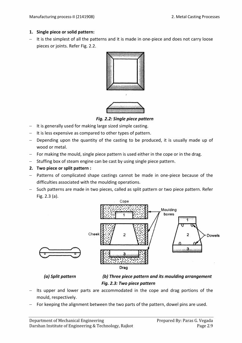
1. Single piece or solid pattern: − It is the simplest of all the patterns and it is made in one-piece and does not carry loose
pieces or joints. Refer Fig. 2.2.
Fig. 2.2: Single piece pattern
− It is generally used for making large sized simple casting. − It is less expensive as compared to other types of pattern. − Depending upon the quantity of the casting to be produced, it is usually made up of
wood or metal. − For making the mould, single piece pattern is used either in the cope or in the drag. − Stuffing box of steam engine can be cast by using single piece pattern. 2. Two piece or split pattern : − Patterns of complicated shape castings cannot be made in one-piece because of the
difficulties associated with the moulding operations. − Such patterns are made in two pieces, called as split pattern or two piece pattern. Refer
Fig. 2.3 (a).
(a) Split pattern (b) Three piece pattern and its moulding arrangement
Fig. 2.3: Two piece pattern − Its upper and lower parts are accommodated in the cope and drag portions of the
mould, respectively. − For keeping the alignment between the two parts of the pattern, dowel pins are used.

2. Metal Casting Processes Manufacturing process-II (2141908)
Prepared By: Paras G. Vegada Department of Mechanical Engineering Page 2.10 Darshan Institute of Engineering & Technology, Rajkot
− Patterns of more complicated casting are made in more than two pieces for their easy removal and they have three piece flasks for the moulding purpose. Refer Fig. 2.3 (b).
− Casting of taps and water stop cocks are produced by using split patterns 3. Loose piece pattern : − Some patterns embedded in the moulding sand cannot be withdrawn, hence such
patterns are made with one or more loose pieces for their easy removal from the moulding box.
− These patterns are known as loose piece patterns. Refer Fig. 2.4.
Fig. 2.4: Loose piece pattern
− Loose pieces like A and B as shown in Fig. 2.4 remain attached with the main body by using dowel pins.
− These patterns consume more time for moulding operation and require more labour work.
4. Cope and Drag pattern : − It is another form of split pattern. − The pattern is split about a suitable surface or line. − Each half of the pattern is fixed to a separate plate and besides the pattern it has
provision for moulding runner and gates. − Each half of the pattern is moulded separately in a separate moulding box and then
assembled for pouring. − These patterns are used for producing large casting. 5. Gated pattern: − To increase the strength and reduce the tendency to warp, gated patterns are generally
made of metals. − By using gated patterns number of casting can be made at a time, hence they are used in
mass production system. − The sections connecting various patterns serve as a runner and gates. Refer Fig. 2.5.
Fig. 2.5: Gated pattern

Manufacturing process-II (2141908) 2. Metal Casting Processes
Department of Mechanical Engineering Prepared By: Paras G. Vegada Darshan Institute of Engineering & Technology, Rajkot Page 2.11
− This facilitates filling of the mould with molten metal in better manner and reduces the required time and labour work.
− These patterns are used for producing small castings. 6. Match plate pattern : − These patterns are made in two pieces i.e. one piece mounted on one side and the other
on the other side of the plate, called as match plate. − The plate may carry one pattern or group of patterns mounted in the same way on its
two sides. Refer Fig. 2.6.
Fig. 2.6: Match plate pattern
− The plate can be of wood, aluminum, magnesium or steel. − The match plate has runner and gates attached with it. − Match plate patterns are generally used in machine moulding because they produce
accurate casting at faster rates. − Piston rings of I. C. engines are made by using these patterns. 7. Sweep pattern : − Sweep pattern is just a form made on a wooden board which sweeps the casting shape
into the sand all around the circumference. − The equipment consists of a base, placed in the sand, vertical spindle and a wooden
template called as sweep. − The sweep is rotated about the spindle or post, to form the cavity as shown in Fig. 2.7.
Fig. 2.7: Sweep pattern

2. Metal Casting Processes Manufacturing process-II (2141908)
Prepared By: Paras G. Vegada Department of Mechanical Engineering Page 2.12 Darshan Institute of Engineering & Technology, Rajkot
− Once the mould is ready, sweep pattern and post can be removed. − It saves lot of time and labour work as compared to making a full pattern. Sweep
patterns are used for making large casting of circular sections and symmetrical shape; for example, large kettles of cast iron.
8. Skeleton pattern : − When the casting size is very large, but easy to shape and few are to be made, then it is
not economical to make a large solid pattern of that size. − In such cases, a pattern consisting of a wooden frame and strips is made which is called
as skeleton pattern.
Fig. 2.8: Skeleton pattern
− It is filled with loam sand and rammed. − A strickle is used for giving the desired shape to the sand and for removing the extra
sand. − Fig. 2.8 shows the skeleton pattern for a hollow pipe. − Skeleton patterns are used for producing large casting like turbine casing, water pipes, L-
bends, etc. 9. Segmental pattern : − The working principle of segmental pattern is similar to sweep pattern. − The main difference between them is that, a sweep is given a continuous revolving
motion to generate the required shape, whereas a segmental pattern is a portion of the solid pattern itself and the mould is prepared in parts by it.
− It is mounted on a central pivot and it completes one portion of the mould and then moves to the next portion. Refer Fig. 2.9.

Manufacturing process-II (2141908) 2. Metal Casting Processes
Department of Mechanical Engineering Prepared By: Paras G. Vegada Darshan Institute of Engineering & Technology, Rajkot Page 2.13
Fig. 2.9: Segmental pattern
− These patterns are used for producing large circular casting like big gears, wheel rims, etc.
10. Follow board pattern : − A follow board is a wooden board and is used for supporting a pattern which is very thin
and fragile. − With the help of follow board support under the weak pattern, the drag is rammed and
then the follow board is removed. Refer Fig. 2.1 0. − A follow board also forms the natural parting line of the mould or the casting. − Follow board patterns are used for casting master patterns for many applications
Fig. 2.10: Follow board pattern
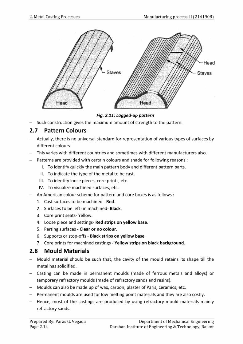
11. Lagged-up pattern − Cylindrical work pieces such as cylinders, pipes or columns are built up with lag (stave)
construction. − Lags (staves) are longitudinal strips of wood which are bevelled on each side to make the
joint tight from outside and glued or screwed to the end pieces of wood called as heads. Refer Fig. 2.11.
2. Metal Casting Processes Manufacturing process-II (2141908)
Prepared By: Paras G. Vegada Department of Mechanical Engineering Page 2.14 Darshan Institute of Engineering & Technology, Rajkot
Fig. 2.11: Lagged-up pattern
− Such construction gives the maximum amount of strength to the pattern.
2.7 Pattern Colours − Actually, there is no universal standard for representation of various types of surfaces by
different colours. − This varies with different countries and sometimes with different manufacturers also. − Patterns are provided with certain colours and shade for following reasons :
I. To identify quickly the main pattern body and different pattern parts. II. To indicate the type of the metal to be cast.
III. To identify loose pieces, core prints, etc. IV. To visualize machined surfaces, etc.
− An American colour scheme for pattern and core boxes is as follows : 1. Cast surfaces to be machined - Red. 2. Surfaces to be left un machined- Black. 3. Core print seats- Yellow. 4. Loose piece and settings- Red strips on yellow base. 5. Parting surfaces - Clear or no colour. 6. Supports or stop-offs - Black strips on yellow base. 7. Core prints for machined castings - Yellow strips on black background.
2.8 Mould Materials − Mould material should be such that, the cavity of the mould retains its shape till the
metal has solidified. − Casting can be made in permanent moulds (made of ferrous metals and alloys) or
temporary refractory moulds (made of refractory sands and resins). − Moulds can also be made up of wax, carbon, plaster of Paris, ceramics, etc. − Permanent moulds are used for low melting point materials and they are also costly. − Hence, most of the castings are produced by using refractory mould materials mainly
refractory sands.

Manufacturing process-II (2141908) 2. Metal Casting Processes
Department of Mechanical Engineering Prepared By: Paras G. Vegada Darshan Institute of Engineering & Technology, Rajkot Page 2.15
− The choice of a particular mould material depends on the following factors : (i) Cost of the material (ii) Quality of casting required (iii) Number of casting required
(iv) Accuracy of the casting (v) Shape and size of the casting (vi) Material to be cast, etc.
2.8.1 Moulding Sand − Sand is the most widely used mould material for casting ferrous and nonferrous metals
from few grams to few tons. − The main reason for this is that, the sand fulfills service requirements at reasonably
lower cost than the other materials. − When the Sand is properly mixed with other elements, it constitutes one of the best
materials for the mould. − The sources of moulding sands are river beds, lakes, sea and deserts. 2.8.2 Types of Moulding Sand All types of sands used in the foundry can be grouped as:
1. Natural sand: − Natural sand can be used directly for making moulds as soon as it is received fromits
source. − It contains binding materials (5 to 20% clay) and needs only water (5 to 8 %) to mix
before making the mould. − It can maintain moisture content for a long time and also contain considerable amount
of organic matter. − This type of sand permits easy patching and finishing of moulds. − Natural sands are less refractory than synthetic sands and also less costly. − Hence, natural sands are used for cast iron and nonferrous casting. 2. Synthetic sand : − Synthetic sand consists of natural sand with or without clay, moisture and binder like
bentonite. − Hence, this sand is formulated sand. − These types of sand are used for steel and other ferrous and non-ferrous alloy casting. − Synthetic sand has following advantages as compared to natural sand :
o It requires less proportion of binder. o Higher refractoriness and permeability. o Properties can be easily controlled. o Refractory grain size is more uniform. o It is more suitable in mass production and mechanised foundries. o It requires less storage space.
1. Natural sand 2.Synthetic sand 3.Special sands

2. Metal Casting Processes Manufacturing process-II (2141908)
Prepared By: Paras G. Vegada Department of Mechanical Engineering Page 2.16 Darshan Institute of Engineering & Technology, Rajkot
3. Special sands : − The special sand includes green sand, loam sand, core sand, parting sand, facing sand
and backing sand. a. Green sand : − It is the sand which is in condition and contains 5% of water and 15 to 30% of clay. − Moulds and cores both can be made up of green sand. − Green sand moulds are poured in the green condition (not dried). − It is preferred for producing simple, small and medium sized casting. b. Loam sand: − It contains more amount of clay as compared to other sands i.e. up to 50%. − Loam sand dries hard. − Its ingredients are fine sand, finely ground refractories, clay, graphite and fibrous
reinforcement. − It is used for making mould for heavy and large parts. c. Core sand: − Core sand is different from moulding sand as it has very low clay content and their grain
size is large to increase the permeability. − It is silica sand mixed with core oil which is composed of linseed oil, resin, light mineral
oil and other binding materials. − Core sand is a suitable sand mixture, also used for making cores. d. Parting sand: − It consists of dried silica sand, sea sand or burnt sand. − It is used to keep the green sand from sticking to the pattern and also to allow the sand
on the parting surface of the cope and drag to separate without clinging. − Its parting compounds may be dry or liquid. − Dry parting substances are charcoal, ground bone and limestone, ground nut shells, etc.
whereas liquid substances are petroleum jelly mixed with oil, paraffin and stearic acid. e. Facing sand: − It is fresh and specially prepared moulding sand which covers ~he pattern all around it,
thus forms the face of the mould cavity. − It comes in direct contact with the molten metal being poured; hence it should possess
much improved properties than other sands. − Its use reduces the mould material cost. − Various facing materials are plum bags, graphite, talc, molasses, etc. f. Backing sand: − It is the sand which backs up the facing sand and does not come in direct contact with
the pattern. − This sand has black colour and hence, sometimes called as black sand. − It should be cleaned off the foreign matter like fins, nails, etc. before use. − It is the floor sand which can be used again and again.

Manufacturing process-II (2141908) 2. Metal Casting Processes
Department of Mechanical Engineering Prepared By: Paras G. Vegada Darshan Institute of Engineering & Technology, Rajkot Page 2.17
2.8.3 Property of Moulding Sand Moulding sand is used to produce sound castings. Hence, it should possess following desirable properties: 1. Flow ability or plasticity : − It is the ability of the moulding sand to get compacted to a uniform density. − It assists moulding sand to flow and pack all-around the pattern and take up the desired
shape. − It increases with the amount of clay and water. 2. Green strength : − It is the strength of the sand in the green or moist condition. − A mould which has adequate green strength will retains its shape and does not distort or
collapse, even after the pattern has been removed from the moulding box. − It helps in making and handling the moulds. − If the mould is hardened in contact with the pattern surface with adequate green
strength, then high degree of dimensional accuracy and stability can be obtained. 3. Dry strength: − It is the strength of the moulding sand in the dry state. − A sand must have sufficient dry strength to withstand erosion of the mould wall sand
enlargement of mould cavity during the flow of molten metal. − It is related to grain size, binder and water content. 4. Permeability or porosity : − Molten metal always contain some amount of dissolved gases which are evolved when
the metal solidifies. − Also, when the molten metal comes in contact with moist sand, it generates steam or
water vapour. − If these gases and water vapour generated by moulding sand do not find opportunity to
escape completely through the mould, then they will form gas hole sand pores in the casting.
− Hence, the sand must be porous to allow the gases and steam generated within the moulds to be removed freely.
− This property of sand is known as permeability or porosity. 5. Refractoriness: − It is the ability of moulding sand to withstand high temperatures without fusion,
cracking and buckling, hence facilitating a clean casting. − The amount of this property depends upon the metal which is to be cast. − If sand lacks this property, then it slags on the surface of the mould and smooth casting
surface can be obtained. 6. Adhesiveness: − It is the property of moulding sand because of which it is capable of adhering to the
surface of other materials.

2. Metal Casting Processes Manufacturing process-II (2141908)
Prepared By: Paras G. Vegada Department of Mechanical Engineering Page 2.18 Darshan Institute of Engineering & Technology, Rajkot
− Also, with this property gaggers are able to hold bulky sand projections of the mould. − Due to this property, the heavy sand mass is successfully held in a moulding flask and
manipulated as required, without any risk of its falling down. 7. Cohesiveness : − It is the property of the sand due to which sand particles stick together. − This property helps in withdrawing the pattern from the mould without damaging the
mould surfaces and edges. − Due to cohesiveness, the mould faces get adequate strength to withstand the pressure
of the flowing molten metal and do not get washed under this pressure. − This property is similar to the green strength. − It depends upon the grain size, clay and moisture content. 8. Thermal stability : − To avoid breaking, buckling and flaking off of mould surface at higher temperatures,
sand possesses dimensional thermal stability. − If not, the casting may have defects like cuts and washes. 9. Collapsibility : − It is the property due to which the sand mould automatically collapses after freezing of
the casting, to allow the free contraction of the metal. − If this property of the sand is absent, then the casting will result in tears and cracks. 2.8.4 Ingredient of Moulding Sand The main constituents of moulding sand are : 1. Sand: − The sand which forms the major portion of the moulding sand is essentially a silica grain. − It is river sand which is used with or without washing. − The shape of the grains may be round, sub angular, angular or very angular. − The shape and size of these grains greatly affect the properties of the moulding sand. − The grains of the moulding sand may be coarse or fine grains. − The coarse grains have more void space between the grains which increases
permeability, whereas a fine grain lowers the permeability. − Silica sand, with rounded grains, gives much better compatibility as compared to angular
grains, because sand with rounded grains has the greatest degree of close packing of particle.
2. Binder: − Moulding sand binders are less refractory as compared to moulding sand. − Binders produce cohesion between the moulding sand grains in the green or dry
condition. − They give strength to the moulding sand so that it can retain its shape as mould cavity. − If the amount of binder increases, permeability of moulding sand decreases.
1. Sand 2. Binder 3.Additives 4. Water

Manufacturing process-II (2141908) 2. Metal Casting Processes
Department of Mechanical Engineering Prepared By: Paras G. Vegada Darshan Institute of Engineering & Technology, Rajkot Page 2.19
− The most commonly used binders are as follows : o Organic binders o Inorganic binders
− Organic binders are mostly used for core making. The common binders in this group are: a. Linseed oil b. Dextrin
c. Molasses d. Pitch
− Commonly used inorganic binders are clay, sodium silicate and Portland cement. − Clay binder which is most widely used have following types:
a. Bentonite b. Fire clay
c. Limonite d. Ball clay
e. Kaolonite
− Out of these all clay binders, bentonite is most commonly used. 3. Additives: − The basic constituents of moulding sand mixture are sand, binder and water. − Materials other than the basic ingredients are also added to the moulding sand mixtures
in small quantities for the following purposes : − To enhance the existing properties. − To develop certain other properties like resistance to sand expansion defects, etc. − The most commonly used additives are as follows: a. Coal dust: − It is mostly used in the sand for the grey iron casting. − It reacts chemically with the oxygen present in the sand pores and thus, produces a
reducing atmosphere at the mould metal interface and prevents oxidation of the metal. − It reduces cohesiveness and strength of the sand. b. Sea coal: − It is a finely ground soft coal an<:l is widely used in sands for grey; iron castings. − It restricts the movement of the mould wall and improves surface finish. − It reduces hot strength and permeability of the mould and requires more amount of
water in the sand. c. Corn flour or cereals : − It promotes wall movement of the mould by being volatized by heat and reduces
expansion defects. − It improves the strength, toughness and collapsibility and reduces permeability and flow
ability of the sand. − Its proportion in the sand varies from 0.25 to 2.0 %. d. Silica flour: − It increases hot strength and decreases metal penetration into the mould. − It reduces expansion defects and improves surface finish. − It may be added up to 35 %. e. Wood flour: − It promotes wall movement of the mould.

2. Metal Casting Processes Manufacturing process-II (2141908)
Prepared By: Paras G. Vegada Department of Mechanical Engineering Page 2.20 Darshan Institute of Engineering & Technology, Rajkot
− It reduces expansion defects; increases collapsibility; improves surface finish and thermal stability of the mould.
− It may be added from 0.5 to 2.0 %. f. Pitch: − It increases hot strength and surface finish on ferrous casting. − It is added upto 2.0 %; if higher proportion is added it reduces the green strength. g. Fuel oil : − It is added to reduce the requirement of the free water in the sand. h. Dextrin and molasses: − Its addition increases the dry strength of the mould. − It is almost similar to corn flour. 4. Water: − The amount of clay added to the moulding sand will not give the required strength and
bond, until a suitable quantity of water is mixed with it. − The amount of water may vary from 1.5 to 8.0 %. − Water added to the sand mixture partly gets absorbed by clay and partly remains free,
which is called as free water. − The free water acts as a lubricant and affects following properties: .
o It increases plasticity. o It improves mould ability. o It reduces the strength of the sand mixture.
− For given amount of clay and its types, there is an optimum requirement of the water. − If the amount of water is less, it does not develop proper strength and plasticity,
whereas if water content is more, then it results in excessive plasticity and dry strength. 2.9 Sand Preparation and Conditioning − The best selected sand and binders will not produce good casting, until they are properly
and efficiently mixed and prepared. − Sand preparation means mixing the moulding sand ingredients such as sand, binder,
moisture and other additives. − Mixing can be done manually or by using mechanical mixers. − An operation in addition with sand preparation is called as sand tempering, which is a
process by which adequate amount of moisture is added to the moulding sand to make it workable.
− Sand conditioning consists of preparing of the moulding sand, so that it becomes suitable for moulding purposes.
Functions of sand preparation and conditioning: The functions of sand preparation are as follows: − To develop optimum properties in the moulding sand. − To obtain even distribution of sand grains throughout the bond. − To add suitable amount of water to activate clay binder.
Manufacturing process-II (2141908) 2. Metal Casting Processes
Department of Mechanical Engineering Prepared By: Paras G. Vegada Darshan Institute of Engineering & Technology, Rajkot Page 2.21
− To deliver sand at the suitable temperature. − To remove impurities from the moulding sand. Steps involved in preparation of sand: − Remove all the impurities and undesirable matters such as nails, fins, hard sand lumps,
etc. − With the help of mechanical mixer i.e. Muller, start the mixing of sand ingredients in dry
state. − Temper the moulding sand ingredients and continue mixing or mulling action till there is
a uniform distribution of the ingredients. − Then the sand is treated by an Aeration Process which separates sand grains into
individual particles. − Aerated sand is easy to handle and use and provides better moulding results. − Aeration is achieved by power operating riddles, screening, beating the sand or
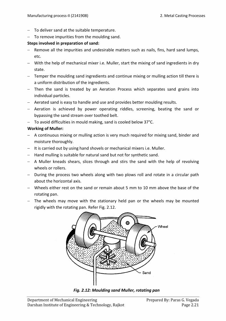
bypassing the sand stream over toothed belt. − To avoid difficulties in mould making, sand is cooled below 37°C. Working of Muller: − A continuous mixing or mulling action is very much required for mixing sand, binder and
moisture thoroughly. − It is carried out by using hand shovels or mechanical mixers i.e. Muller. − Hand mulling is suitable for natural sand but not for synthetic sand. − A Muller kneads shears, slices through and stirs the sand with the help of revolving
wheels or rollers. − During the process two wheels along with two plows roll and rotate in a circular path
about the horizontal axis. − Wheels either rest on the sand or remain about 5 mm to 10 mm above the base of the
rotating pan. − The wheels may move with the stationary held pan or the wheels may be mounted
rigidly with the rotating pan. Refer Fig. 2.12.
Fig. 2.12: Moulding sand Muller, rotating pan

2. Metal Casting Processes Manufacturing process-II (2141908)
Prepared By: Paras G. Vegada Department of Mechanical Engineering Page 2.22 Darshan Institute of Engineering & Technology, Rajkot
− Plows stir the sand and bring it under the wheels, whereas wheels mix the sand with a squeezing action.
− After mixing of the sand, it may be taken out from a drop door, which is provided at the bottom of the muller.
2.10 Sand Testing − Production of sound casting mainly depends upon uniform and good quality of moulding
sand. − Hence, the moulding sand is expected to have many good properties. − These properties depend on the shape and size of sand grains and the amount and
distribution of the other constituents added to the sand. − In order to control these factors effectively, a number of tests are performed in foundry
laboratories, which indicate the moulding sand performance and helps the foundry men in controlling the moulding sand properties.
− Some of the common tests which are performed in the foundry ·laboratories are as follows: 1. Moisture content test 2. Clay content test 3. Permeability test 4. Grain fineness test
5. Mould hardness test 6. Refractoriness test 7. Compression strength test
Sample preparation: − The tests are conducted on a sample of standard sand. − The samples are prepared by ramming sand in a specimen ram tube on sand rammer. − The shape of the sand samples varies as per the nature of the test. − Various sand samples used in testing are :
o Cylindrical green sand sample, for testing compressive and shear strength and permeability.
o Dry sand core specimen for bending test and tensile strength test. 2.10.1 Moisture Content Test − Moisture is one of the most important factors which control the properties of moulding
sand. − Low moisture in the moulding sand does not develop strength properties and high
moisture decreases permeability and adds to other problems associated with moulding operations.
− The moisture content test is carried out by using separate moisture determining apparatus.

Manufacturing process-II (2141908) 2. Metal Casting Processes
Department of Mechanical Engineering Prepared By: Paras G. Vegada Darshan Institute of Engineering & Technology, Rajkot Page 2.23
Fig. 2.13: Moisture determining apparatus
− It consists of a cast iron base, an infrared heating bulb fitted in a shade and a drying pan with handle. Refer Fig. 2.13
Procedure: − 20 to 40 grams of prepared sand sample is placed in the pan. − The pan is slided and fitted under the shade and the bulb is switched on . − It is heated by an infrared heater bulb for 2 to 3 minutes. − The moisture in the moulding sand is thus evaporated. − The switch is put off; pan removed and sample is reweighted. − The percentage of moisture can be calculated from the difference in weights of the
original moist and the consequently dried sample of the sand. − It is then expressed as a percentage of the total weight of the sand sample. 2.10.2 Clay Content Test − For testing purposes the clay in the moulding sand is defined as particles which fail to
settle one inch per minute when suspended in water. − These are generally less than 20 microns. − The apparatus used for this purpose is called as mud or clay content tester. − It consists of a cast iron base, stirring shaft with paddles driven by an electric motor and
an adjustable support for the glass beaker. Procedure: − Take a sample of 50 grams of dry sand which is dried at 1 05°C for an hour. − Place a sample in a wash bottle and add 475 ml of distilled water and 2.5 to 3 % of
NaOH. − Stir the contents for 5 minutes using stirrer. − Fill the wash bottle with water upto the mark indicated on it (generally 6 inches).

2. Metal Casting Processes Manufacturing process-II (2141908)
Prepared By: Paras G. Vegada Department of Mechanical Engineering Page 2.24 Darshan Institute of Engineering & Technology, Rajkot
− After the sand, etc. has settled for about 10 minutes, siphon out the water from the wash bottle, which leaves a minimum depth of water i.e. one inch in the bottom of the wash bottle.
− Add more water to the sand thus left in the wash bottle and stir the constituents again till the sand settles down.
− Repeat the above step until the water over the settled sand is clean, which assures that the whole amount of clay has been removed from the sand.
− The bottle is placed in an oven and after the sand is dried out, a sample is weighed. − The percentage of the clay is determined by the difference in the initial and the final
weights of the sample. 2.10.3 Permeability Test − Permeability is that property of moulding sand which permits the escape of water
vapour (steam) and other gases generated in the mould during hot metal pouring. Permeability depends on the following factors : o Grain shape and size o Grain distribution o Binder and its contents
o Water amount in the moulding sand
o Degree of ramming − Before permeability test, a standard sized sand specimen is rammed by a specimen
rammer. − For measuring the permeability of sand, a permeability tester is used which consists of
following parts (Refer Fig. 2.14) : o An inverted bell jar, which floats in a water seal and it can permit 2000 c.c. of air
to flow. o Specimen tube for holding the sand specimen. o A manometer for measuring air pressure.
Fig. 2.14: Permeability tester

Manufacturing process-II (2141908) 2. Metal Casting Processes
Department of Mechanical Engineering Prepared By: Paras G. Vegada Darshan Institute of Engineering & Technology, Rajkot Page 2.25
Procedure: − 2000 c.c. of air is held in an inverted bell jar and forced to pass through the sand
specimen. − A situation comes when the air entering in the specimen is equal to the air escaped
through the specimen. − It gives a stabilized pressure reading on the manometer and it can be read on the
provided scale. − At the same time, the time required for the 2000 c.c. of air to pass through the specimen
of sand is recorded by using stop watch. − Finally, calculate the permeability by using following relation :
−
Permiability Number =
V = Volume of air passing through the specimen in c.c. (standard value is 2000 c.c.) h = Height of the specimen (stand
V ha p t
Where
×× ×
2 2
2
ard value is 5.08 em) a = Areas of the specimen in cm (standard value is 20.268 cm ) p = Air pressure in gm/cm . t = Time taken by 2000 c.c. of air to pass through the sand specimen in minutes.
2000 5.08 501.282Permiability number = = 20.268 p t p t
×× × ×
2.10.4 Grain Fineness Test − This test determines the grain size, distribution and grain fineness. − It is performed on the dried sample for which all clay substances have been removed. − The grain size of moulding sand provides a significant effect on its permeability. − The apparatus required for determining grain fineness number is shown in Fig. 2.15.
Fig. 2.15: Grain fineness tester

2. Metal Casting Processes Manufacturing process-II (2141908)
Prepared By: Paras G. Vegada Department of Mechanical Engineering Page 2.26 Darshan Institute of Engineering & Technology, Rajkot
− It consists of a number of standard sleeves mounted one above the other on a power-driven shaker.
− There are eleven standard sleeves mounted one above the other and a pan is placed under the bottom-most sieve.
− The coarsest sleeve is placed at the top and finest sieve at the bottom. − The rest being placed below one another in order of fineness from top to bottom. − The whole unit is shaken by an electric motor. − The sample of dry sand, which is free of clay, is placed in upper-most sleeve and sand is
vibrated for definite period of time. − The amount. of sand retained on each sleeve is weighed and percentage distribution of
grains is found. − To obtain the American Foundry Association (AFA) fineness number, the weight of sand
on each sleeve and pan is multiplied by a factor shown against each sleeve and pan as shown in the Table 2.2.
− The grain fineness number is obtained by adding all the resulting products and dividing the total by percentage of sand grains retained.
Sum of productsTotal sum of the percentages of sand reta
Ai
FA grain finenened on pan and
ss numbeach sl
er = eeve
2.10.5 Compression Strength Test − The compression strength testing apparatus for sand is shown in Fig. 2.15 (a). − It consists of hand wheel which is rotated to build up the hydraulic (oil) pressure on the
specimen.
Fig. 2.15 (a): Compression strength testing equipment
− For measuring the deformation occurring in the specimen the dial indicator is provided on the apparatus.
− There are two indicators are provided on the apparatus. The first one is used for testing low strength sands (moulding sands) and the second one is used for testing high strength sands (core sands).
Manufacturing process-II (2141908) 2. Metal Casting Processes
Department of Mechanical Engineering Prepared By: Paras G. Vegada Darshan Institute of Engineering & Technology, Rajkot Page 2.27
− The same apparatus is also used for testing the tensile strength, shear strength, transverse strength, etc. of sand.
2.11 Core − Core is a sand shape or form which makes the contour of a casting for which no
provision has been made in the pattern for moulding. − Core may be made up of sand, plaster, metal or ceramics. − Core is an obstruction which when positioned in the mould, does not permit the molten
poured metal to fill the space occupied by the core hence produce hollow casting. − Cores are used as inserts in moulds to form design features which are difficult to be
produced by simple moulding. Functions of core : − Core provides a means of forming the main internal cavity for hollow casting. − Core provides external undercut feature. − Cores can be inserted to obtain deep recesses in the casting. − Cores can be used to increase the strength of the mould. − It can be used as a part of gating assembly. − It can form a part of green sand mould and can also be used to improve the mould
surface. Essential characteristics of core: − A dry sand core must possess following properties : − It should have sufficient strength to support itself without breaking. − It should have high permeability and high refractoriness. − It should have smooth surface to ensure a smooth casting. − It should have high collapsibility, to assist the free contraction of the solidifying metal. − It should have those ingredients which does not generate mould gases. Core Applications − Core and its form increase the versatility of moulding processes and operations. − In addition to recess forming and holes in the casting, cores are used as follows :
o Cores are used for mould making. o Cores can be used as strainer, gates and pouring cups. o Cores are used for increasing production from match plate pattern. o Cores can be used as core mould in centrifugal casting process. o Also it can be used as slab core for increasing castings output from one
mould. 2.11.1 Core Sand and Its Ingredients − Core sand is a sand mixture suitable for cores. − Core sand mixture consists of sand grains, binders for green and cured strength and
other additives used for special purposes. − The commonly used core sand mixture consists of sand, 1 % core oil, 1 % cereal and 2.5
to 6 % of water.

2. Metal Casting Processes Manufacturing process-II (2141908)
Prepared By: Paras G. Vegada Department of Mechanical Engineering Page 2.28 Darshan Institute of Engineering & Technology, Rajkot
− Core sand is almost similar to moulding sand but the main difference is that core sand has very low clay content and larger grain size.
− Large grain size assures higher permeability. Core sand Ingredients:
Core sand ingredients or core materials are as follows: a. Granular refractories :
Some of the commonly used granular refractories are : a. Dry silica sand b. Carbon
c. Zircon d. Olivin
e. Chamotte
b. Core binders : A core binder is used to,
− Hold sand grains together. − Give strength to cores. − Make the cores erosion resistant − Impact adequate collapsibility to cores.
Core binders are of following types: − Organic binders (core oil, cereal, pitch, wood flour, synthetic resins, etc.) − Inorganic binders (fire clay, bentonite, silica flour, iron oxide, etc.) − Other binders (cement, sodium silicate, etc.) c. Water: − In a core sand mixture, water content may vary from 3 to 7 % . − Binders and additives work only when moisture is present. − Correct amount of water develops good green strength, edge and scratch hardness,
good tensile strength, etc. − Excessive amount of moisture adds difficulties in making and baking of cores. d. Additives: − The additives used for core sand are almost similar to moulding sand, hence refer
section 2.8.4. 2.11.2 Core Making
Core making basically consists of following steps :
1. Core sand preparation : − Core sand preparation is similar to moulding sand preparation. Refer section 2.9. 2. Core making : − Small cores can be made manually in hand rammed core boxes. − Cores on mass scale are rapidly produced on various core making machines which are,
o Jolt machine o Shell core machine o Core blower
1. Core sand preparation 2.Core making 3.Core baking 4.Core finishing or dressing 5.Setting the cores

Manufacturing process-II (2141908) 2. Metal Casting Processes
Department of Mechanical Engineering Prepared By: Paras G. Vegada Darshan Institute of Engineering & Technology, Rajkot Page 2.29
o Sand slinger o Core roll over machine o Core extrusion machine 3. Core baking: − After the cores are prepared they are baked in baking furnace where the moisture is
removed from the core. − In the green state, cores have round shape hence they are placed on the core plate for
baking, where they tend to flatten. − The special shapes, which support the green sand cores having curved surfaces, are
known as core driers. − After supporting on the core drier, they are sent to ovens for baking. − The core oven may be batch type or continuous type. 4. Finishing of cores : − After baking, cores are given certain finishing operation before they are finally set in the
mould. − The fins and other sand projections are removed from the sand surface of the cores by
rubbing or filing, to bring them to correct dimensions and to provide a good surface finish.
− The cores are also coated with refractory or protective materials to improve their refractoriness.
− The surface may be coated with heat resistant paint. − Core coating materials are finely ground graphite, silica and zircon flour. − Finally core assembling is done; it means two or more parts of the core are joined
together by pasting, welding or bolting before the core can be set in the mould. 5. Setting the cores : − Core setting means placing cores in the mould. − To obtain correct cavities in the casting, the cores should be accurately positioned in the
moulds.
2.12 Types of Cores − Various types of cores of different designs and sizes are used in different ways in
foundry work. A general way of classifying them is, according to their shapes and positions in the prepared moulds. Their main types are as follows: 1. Horizontal core 2. Vertical core 3. Hanging core
4. Balanced core 5. Ram up core 6. Kiss core
7. Drop core
a. Horizontal core : − A horizontal core is positioned horizontally in the mould. Refer Fig. 2.16.

2. Metal Casting Processes Manufacturing process-II (2141908)
Prepared By: Paras G. Vegada Department of Mechanical Engineering Page 2.30 Darshan Institute of Engineering & Technology, Rajkot
Fig. 2.16: Horizontal core
− According to the shape of the cavity required in the casting, a horizontal core may have any shape.
− Uniformly sectioned horizontal cores are mostly placed at parting line. b. Vertical core : − It is similar to horizontal core, except that it is fitted in the mould with its axis vertical.
Refer Fig. 2.17. − The top end of the core is provided with more amount of taper, to have a smooth fitting
of the cope on the core.
Fig. 2.17: Vertical core
− A major portion of the vertical core generally remains in the drag. c. Hanging core : − Hanging core is also called as cover core as shown in Fig. 2.18.
Fig. 2.18: Hanging or cover core
Manufacturing process-II (2141908) 2. Metal Casting Processes
Department of Mechanical Engineering Prepared By: Paras G. Vegada Darshan Institute of Engineering & Technology, Rajkot Page 2.31
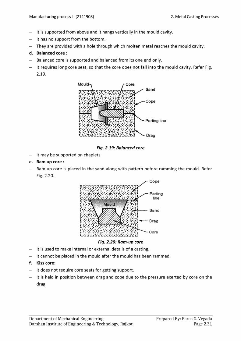
− It is supported from above and it hangs vertically in the mould cavity. − It has no support from the bottom. − They are provided with a hole through which molten metal reaches the mould cavity. d. Balanced core : − Balanced core is supported and balanced from its one end only. − It requires long core seat, so that the core does not fall into the mould cavity. Refer Fig.
2.19.
Fig. 2.19: Balanced core
− It may be supported on chaplets. e. Ram up core : − Ram up core is placed in the sand along with pattern before ramming the mould. Refer
Fig. 2.20.
Fig. 2.20: Ram-up core
− It is used to make internal or external details of a casting. − It cannot be placed in the mould after the mould has been rammed. f. Kiss core: − It does not require core seats for getting support. − It is held in position between drag and cope due to the pressure exerted by core on the
drag.

2. Metal Casting Processes Manufacturing process-II (2141908)
Prepared By: Paras G. Vegada Department of Mechanical Engineering Page 2.32 Darshan Institute of Engineering & Technology, Rajkot
Fig. 2.21: Kiss core
− To obtain a number of holes in a casting, a number of kiss cores can be simultaneously positioned. Refer Fig. 2.21.
g. Drop core: − Drop core is also called as stop off core. − It is used to make a cavity which cannot be made with other types of cores. Refer Fig.
2.22.
Fig. 2.22: Drop core
− It is used when a hole recess or cavity required in a casting is not in line with parting surface.
2.13 Core Boxes − Basically, core box is a pattern for making cores. − They are employed for ramming cores in them. − Core boxes provide the required shape to the core sand. The commonly used types of core boxes are as follows: a. Half core box : − Half core box is shown in Fig. 2.23 which can make cylindrical cores. − At one time, half portion of the core is made in the core box.

Manufacturing process-II (2141908) 2. Metal Casting Processes
Department of Mechanical Engineering Prepared By: Paras G. Vegada Darshan Institute of Engineering & Technology, Rajkot Page 2.33
Fig. 2.23: Half core box
− After producing number of half core portions, they are cemented together to make full cylindrical cores.
b. Dump core box : − It is also called as slab core box.
Fig. 2.24: Dump core box
− It is similar to half core box in its construction but, it makes full core at a time, hence used to produce rectangular, square or trapezoidal cores. Refer Fig. 2.24.
c. Split core box : − This type of core box moulds the entire core, but to remove the core after moulding, the
box is separated in two or more parts. Refer Fig. 2.25.
Fig. 2.25: Split core box and rammed core

2. Metal Casting Processes Manufacturing process-II (2141908)
Prepared By: Paras G. Vegada Department of Mechanical Engineering Page 2.34 Darshan Institute of Engineering & Technology, Rajkot
− Two portions of the split core box can be aligned temporarily with the help of dowels. − For making the core, two portions of the split core box are joined and then sand is
rammed. d. Strickle core box : − Sand is rammed in the dump core box. − The top surface of the core in the core box is given a required shape by using trickle
board cut and finished to the desired shape. − A strickle board strikes off excess sand not confirming to its shape.
Fig. 2.26: Strickle core boxes
− A strickle board is made up of wood and in any shape, as per the requirement. Refer Fig. 2.26.
− This me7thod of producing cores is less costly as compared to others. 5. Gang core box: − Gang core box contains a number of cavities, so that more than one core can be
rammed at a time. Refer Fig. 2.27.
Fig. 2.27: Gang core box
6. Loose piece core box : − It is similar to half core box. − But loose piece core box can produce two halves of a core, which may be neither
identical in size nor in shape.

Manufacturing process-II (2141908) 2. Metal Casting Processes
Department of Mechanical Engineering Prepared By: Paras G. Vegada Darshan Institute of Engineering & Technology, Rajkot Page 2.35
Fig. 2.28: Loose piece core box
− It is achieved by inserting loose wooden pieces in the core whenever required. Refer Fig. 2.28.
7. Left and right hand core boxes : − These core boxes are used to make cores for producing pipe bends. − Half of the pipe bend core is made in each core box.
Fig. 2.29: Left and right hand core boxes
− Two halves of pipe bends are then rammed, baked and joint together to form a full core. Refer Fig. 2.29.
2.13.1 Core Prints − Core prints are basically extra projections provided on the pattern. − They form core seats in the mould when pattern is embedded in the sand for mould
making. − Core seats are provided to support all the types of cores. − Though the core prints are the part of pattern, they do not appear on the cast part.
Fig. 2.30: Core print

2. Metal Casting Processes Manufacturing process-II (2141908)
Prepared By: Paras G. Vegada Department of Mechanical Engineering Page 2.36 Darshan Institute of Engineering & Technology, Rajkot
− Fig. 2.30 shows a core positioned in the core seat made by the core print provided on the pattern.
− Core prints are of the following types: o Horizontal core print o Vertical core print
o Cover core print o Wing core print
o Balance core print
2.13.2 Chaplets − During the casting process, if the core gets shifted from its position in the mould, it will
result in a displace cavity and hence a defective casting is obtained. − Hence, a core must be firmly supported in the core seat especially to overcome vertical
core movement, which is due to force exerted by poured molten metal.
Fig. 2:31: Cores supported between the chaplets
− For this purpose, chaplets are provided which can support the cores. − Chaplets are metal shapes which are placed between the mould and core surfaces as
shown in Fig. 2.31. − As the molten metal is poured, chaplet melts and becomes a part of the casting. − But the chaplets should be of the same material which is being cast. − Before use, dirty, rusty, greasy or wet chaplets are properly cleaned and dried. − Fig. 2.32 shows a number of chaplet forms and shapes available commercially.
2.14 Moulds − Prepared moulding sand is packed rigidly around the pattern. − When the pattern is removed, a cavity corresponding to the shape of the pattern
remains in the sand which is known as mould or mould cavity. − Hence, mould is a sort of container which when poured with molten metal produces a
casting of the mould shape. − The process of making the mould is called as mould making. Essential characteristics: − A mould should possess following properties : − Mould should have refractoriness to bear the high heat of molten metal. − It should have strength to hold the weight of the molten metal.

Manufacturing process-II (2141908) 2. Metal Casting Processes
Department of Mechanical Engineering Prepared By: Paras G. Vegada Darshan Institute of Engineering & Technology, Rajkot Page 2.37
− Also, it should produce minimum amount of mould gases. − It should be able to resist the erosive action of the molten metal being poured. − A mould should resist metal penetration into the walls. 2.14.1 Steps in Mould Making − Steps involved in making a sand mould are as follows : 1. Select a suitable moulding box which can accommodate mould cavity, risers and gating
system. 2. Place the drag half of the box on the moulding board with the aligning pins pointing
downwards. 3. Place the drag pattern with parting surface down on the bottom board. Refer Fig. 2.33
(a).
Fig. 2.32: Making a mould
4. Sprinkle the facing sand all around the pattern carefully so that the pattern does not stick to the moulding sand.
5. Fill the drag half with moulding sand and ram the sand uniformly in the moulding box around the pattern.
6. Strike off the excess sand to bring it to the same level of the flask, hence drag half is completed.
7. Sprinkle parting sand over the top of the drag half and roll it over the drag. Refer Fig. 2.33 (b).

2. Metal Casting Processes Manufacturing process-II (2141908)
Prepared By: Paras G. Vegada Department of Mechanical Engineering Page 2.38 Darshan Institute of Engineering & Technology, Rajkot
8. Place the cope pattern on the drag pattern and align by using dowel pins. 9. Place cope half over the rammed drag half. 10. Sprinkle parting sand all around the cope pattern. 11. Erect sprue and riser pins to form suitable sized cavities for molten metal pouring as
shown in Fig. 2.33 (c). 12. Fill the cope with sand and ram it. 13. Remove sprue and riser pins and vent the cope with vent wire. 14. Sprinkle parting sand over the top of the core surface and roll over the cope on the
bottom board. 15. Remove both the cope and drag pattern and repair the mould, if necessary. 16. Cut the gate connecting the sprue basin with the mould cavity. 17. Apply mould coating by a swab. 18. In case of dry sand mould, bake the mould. 19. If required, set the cores in the mould. 20. By inverting cope over the drag close the mould. 21. Finally, clamp the cope with drag and the mould is ready for pouring. Refer Fig. 2.33 (d).
2.15 Moulding Processes − There are different ways of classifying moulding processes. Some of the common ways
are as follows : 1. As per the method used :
i. Floor moulding ii. Pit moulding
iii. Bench moulding iv. Machine moulding
2. As per the mould materials : i. Sand moulding
a. Green sand moulding b. Dry sand moulding c. Loam moulding d. Shell moulding
e. Cement banded sand moulding f. Skin dried sand moulding g. Core sand moulding h. Carbon-dioxide moulding
ii. Plaster moulding iii. Metallic moulding 2.15.1 Floor Moulding − When mould size is large, moulding work is carried out on foundry floor. − This method is mainly used for medium and large sized casting. − The mould has its drag portion in the floor itself and cope portion may be rammed in
box and inverted on the floor. − By this method both green and dry sand mould can be made. − In floor moulding, venting of moulds sometimes creates problem. − Hence, a bed of coke may be laid in the bottom of the mould which is later connected to
the atmosphere by using two vent pipes, erected by the sides of the mould.

Manufacturing process-II (2141908) 2. Metal Casting Processes
Department of Mechanical Engineering Prepared By: Paras G. Vegada Darshan Institute of Engineering & Technology, Rajkot Page 2.39
− This method is used for producing parts such as wheels, pulleys, cylinder covers, ribbed plates, etc.
2.15.2 Bench Moulding − When mould size is small and light in weight, moulding work is carried out on a bench. − By this method, both green and dry sand mould can be made. − Both cope and drag are rammed on the bench itself. − Moulds for both i.e. ferrous and non ferrous casting are made on the bench mould. 2.15.3 Pit Moulding − Castings which are so large that they cannot be made in flasks are moulded in pit dugon
the floor. − By this method, very big jobs can be handled and cast easily. − It is called as pit moulding because the mould is prepared in a pit form. − The mould has its drag part in the pit and a separated cope is rammed. − The depth of drag in pit moulding is so large that the moulder can enter the drag and
prepare it. − A pit is of square or rectangular shape. − Gates, runner, pouring basin, sprue, etc. are made in the cope itself. − Cope and drag are then assembled and sometimes a crane is used for closing the mould. − Pit moulding can be a slow process. 2.15.4 Green Sand Moulding − It is the most widely used moulding process. − The green sand is used for moulding process which consists of silica sand, clay, water
and other additives. − Green sand mixture contains 10 to 15% clay binder, 3 to 6% water and remaining silica
sand. − Green sand mixture is prepared and mould is made by packing the sand around the
pattern. − Cope and drag are assembled and the molten metal is poured when the mould cavity is
neither dried nor baked. − This method is mostly preferred for making small and medium casting and suitable
fornon-ferrous casting. − The parts like railing and gates, moulding boxes, grills, weights, etc. can be made by this
method. 2.15.5 Dry Sand Moulding − This method is almost similar to green sand moulding except that the composition of
sand constituents is different in this case. − While preparing dry sand mixture, special binding materials like resin, clay or molasses
are added to give strong bond to the sand. − Hence, the dry sand mould possesses high strength .
2. Metal Casting Processes Manufacturing process-II (2141908)
Prepared By: Paras G. Vegada Department of Mechanical Engineering Page 2.40 Darshan Institute of Engineering & Technology, Rajkot
− Dry sand moulds are more permeable than green sand moulds. − Casting produced by this method possesses clean and smooth surfaces. − As compared to green sand moulding, this method produces casting with fewer defects. − Dry sand moulding provides better overall dimensional accuracy to the moulds. − But the main disadvantage of this method is, it requires more labour and consumes
more time in completing the mould and mould baking is also an extra work. − Due to high cost and time consuming process, it is not used in mass production. − It is used for producing parts like larger rolls, gear housings, machinery components, etc. 2.15.6 Loam Moulding − It is a very different method of moulding. − In this, a rough structure of component is made by hand using bricks and loam sand. − The sand used is known as loam sand or loam mortar. − Then the desired shape is given to the made structure with the help. of strickle and
sweeps, hence pattern is not required. − After preparing the mould, it is baked to give strength. − This method is mostly used for producing large casting in very small numbers. − It enables to save time, labour and material because use of pattern is avoided. − But not used widely because, it takes time for preparing the mould and skilled moulder
is required. − It is used for producing parts like cylinders, round bottom kettles, gears, huge bells, etc. 2.15.7 Shell Moulding − Shell moulding is suitable for thin walled articles. − It consists of making a mould that has two or more thin shell like parts consisting of
thermosetting resin bonded sand. − Silica sand is mixed with synthetic resin to form a mixture. − The mixture must be dry and free flowing. Procedure of making shell mould: − Fig. 2.33 shows the making of a shell mould and shell core. − Metal pattern is heated to about 175°C to 350°C and clamped over a box containing
sand mixture. − The box and pattern are inverted for a short time. − The mixture when comes in contact with hot pattern, it causes an initial set and binds up
a coherent sand shell next to the pattern, which takes 5 to 10 seconds only. − The thickness of this shell is about 6 to 8 mm and is dependent on pattern temperature,
dwell time on the pattern and sand mixture. − The box and pattern are brought in its original position. − The shell of resin bonded sand is retained on pattern surface while unaffected sand falls
into the box. − The shell on the pattern IS cured by heating it m oven from 250°C to 350ocfor 1 to 3
minutes.

Manufacturing process-II (2141908) 2. Metal Casting Processes
Department of Mechanical Engineering Prepared By: Paras G. Vegada Darshan Institute of Engineering & Technology, Rajkot Page 2.41
Fig. 2.33: Shell moulding process
− The assembly is removed from oven and the shell is stripped off from pattern by ejector pins.
− In order to obtain clean stripping, a silicon parting agent may be sprayed on the pattern. − The shell halves are assembled with clamps supported in a flask with baking materials. − The mould is now ready for pouring. Advantages: − Very high surface finish is obtained. − Sand handling is minimum. − Permeability of the shell is high; hence gases escape readily through them. − Less floor area is required. − Casting defects are minimum. Limitations: − The pattern equipment cost is more. − Not economical for fewer casting. − Complicated jobs cannot be moulded. − Weight and size of casting are limited. Applications: − It is used where greater dimensional accuracy and smoother surface finish are required
as in automobile casting. − Also, used for casting steel, iron or non-ferrous alloys.

2. Metal Casting Processes Manufacturing process-II (2141908)
Prepared By: Paras G. Vegada Department of Mechanical Engineering Page 2.42 Darshan Institute of Engineering & Technology, Rajkot
2.16 Gating System − Gating is the term applied to the method of forming channels in the sand through which
the molten metal travels from the sprue hole to the mould and out of the mould to the riser.
− Gating system refers to all channels by means of which molten metal is delivered to the mould cavity.
− Since the way in which liquid metal enters the mould has a decided influence on the quality and soundness of a casting.
− The different passages for molten metal are carefully designed and produced. − Fig. 2.34 shows the various components of gating system which is composed of:
a. Pouring cups and basins b. Sprue c. Runner
d. Gates e. Riser
Fig. 2.34: Components of gating system
2.16.1 Pouring Cups and Basins Pouring cups: − A pouring cup is a funnel shaped cup which forms the top portion of the sprue. − It makes easier for the ladle or crucible operator to direct the flow of metal from
crucible to sprue. Pouring basins: − The molten metal is not directly poured into the mould cavity.

Manufacturing process-II (2141908) 2. Metal Casting Processes
Department of Mechanical Engineering Prepared By: Paras G. Vegada Darshan Institute of Engineering & Technology, Rajkot Page 2.43
− It is poured into a pouring basin which acts as a reservoir from which it moves smoothly into the sprue.
− It prevents the slag from entering the mould cavity. − It holds back the slag and dirt, which floats on the top and allows only the clean metal to
enter into the sprue. − The basin is cut in various shapes into the cope directly. 2.16.2 Sprue − Sprue is the channel through which the molten metal is brought into the parting plane
where it enters the runner and gates. − The sprue may be square or round and is generally tapered downwards, to avoid
aspiration of air and metal damage. − Sprues up to 20 mm diameter are round in section, whereas larger sprues are generally
rectangular. − In a rectangular sprue, there is less turbulence. 2.16.3 Runner − In large casting, molten metal is generally carried from the sprue base to several gates
around the cavity through a passage called as runner. − Depending upon the shape of the casting, the runner may be located in the cope or drag
part. − To avoid aspiration and turbulence, it should be streamlined. 2.16.4 Gates − A gate is a channel which connects runner with the mould cavity, through which molten
metal flows to fill the mould cavity. − The location and size of the gates are so arranged that, they can feed liquid metal to the
casting at a rate consistent with the rate of solidification. − More than one gate is employed to feed a fast freezing casting. − The gate should not have sharp edges as they may break during pouring and thus carried
with the molten metal into the cavity. − The gates should be located where they can be easily removed without damaging the
casting. − lngate is the end of the gate where it joins the mould cavity and through which the
molten metal will be introduced into the mould cavity. − The leading edge of the molten metal flowing in a stream follows the path of least
resistance and continues to build up kinetic energy. If a runner extension is used, the Kinetic energy may be absorbed hence causing a smoother flow of metal in the runners and into the mould cavity.
− Gate ratio is the ratio of sprue base area to the addition of total runner area and the total ingate area.

2. Metal Casting Processes Manufacturing process-II (2141908)
Prepared By: Paras G. Vegada Department of Mechanical Engineering Page 2.44 Darshan Institute of Engineering & Technology, Rajkot
− Choke is that part of the gating system which has the smallest cross-sectional area. Its function is to control the flow rate of metal and to hold back slag, foreign particle, etc. And float these in the cope side of runner.
− The major types of gates are as follows :
a. Parting line gates : − These gates enter the mould cavity along the parting line separating the cope and drag
portions of the mould. Refer Fig. 2.35. − These gates are the simplest in nature and construction. − Such gates are commonly used and are found to give satisfactory service except when
the mould is very deep.
Fig. 2.35: Parting line gate
b. Top gates: − Top gate is also called as drop gate because the molten metal just drops on the sand in
the bottom of the mould: Refer Fig. 2.36. − A top gate simplifies the moulding with low consumption of additional metal. − There is lot of turbulence in this system.
Fig. 2.36: Top gate
a. Parting line gates b. Bottom gates
c. Top gates d. Side gates
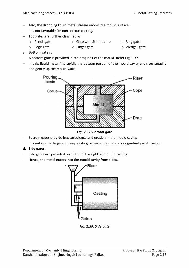
Manufacturing process-II (2141908) 2. Metal Casting Processes
Department of Mechanical Engineering Prepared By: Paras G. Vegada Darshan Institute of Engineering & Technology, Rajkot Page 2.45
− Also, the dropping liquid metal stream erodes the mould surface . − It is not favorable for non-ferrous casting. − Top gates are further classified as :
o Pencil gate o Edge gate
o Gate with Strains core o Finger gate
o Ring gate o Wedge gate
c. Bottom gates : − A bottom gate is provided in the drag half of the mould. Refer Fig. 2.37. − In this, liquid metal fills rapidly the bottom portion of the mould cavity and rises steadily
and gently up the mould walls.
Fig. 2.37: Bottom gate
− Bottom gates provide less turbulence and erosion in the mould cavity. − It is not used in large and deep casting because the metal cools gradually as it rises up. d. Side gates: − Side gates are provided on either left or right side of the casting. − Hence, the metal enters into the mould cavity from sides.
Fig. 2.38: Side gate

2. Metal Casting Processes Manufacturing process-II (2141908)
Prepared By: Paras G. Vegada Department of Mechanical Engineering Page 2.46 Darshan Institute of Engineering & Technology, Rajkot
− It enters near the bottom first, and then as the level of the metal rises in the mould the incoming molten metal starts entering near the surface of the rising metal. Refer Fig. 2.39.
2.16.5 Riser or Feeder Head − A riser is a passage of sand made in the cope to permit the molten metal to rise above
the highest point in the casting after the mould cavity is filled up. Refer Fig. 2.35. − This metal in the riser compensates the shrinkages as the casting solidifies. The functions
of risers are as follows : o To feed metal to the solidifying casting, so that shrinkage cavities are got rid of. o It permits the escape of air and mould gases as the mould cavity is being filled
with the molten metal. o It promotes directional solidification. o Also, it shows that the mould cavity has been completely filled or not.
− A casting solidifying under the liquid metal pressure of the riser is comparatively sound. − According to the location of riser, it is classified as top riser and side riser. Top riser: − It is also called as dead riser or cold riser. It is located at the top of the casting. Refer Fig.
2.39 (a).
Fig. 2.39 (a): Top riser
− These types of risers fill up the coldest metal and are likely to solidify before casting. − By using a top riser there is more saving of material as compared to other risers. Side riser: − It is also called as live riser or hot riser. It is located between runners and casting. Refer
Fig. 2.39 (b).
Fig. 2.39 (a): Side riser
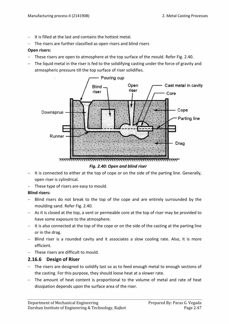
Manufacturing process-II (2141908) 2. Metal Casting Processes
Department of Mechanical Engineering Prepared By: Paras G. Vegada Darshan Institute of Engineering & Technology, Rajkot Page 2.47
− It is filled at the last and contains the hottest metal. − The risers are further classified as open risers and blind risers Open risers: − These risers are open to atmosphere at the top surface of the mould. Refer Fig. 2.40. − The liquid metal in the riser is fed to the solidifying casting under the force of gravity and
atmospheric pressure till the top surface of riser solidifies.
Fig. 2.40: Open and blind riser
− It is connected to either at the top of cope or on the side of the parting line. Generally, open riser is cylindrical.
− These type of risers are easy to mould. Blind risers: − Blind risers do not break to the top of the cope and are entirely surrounded by the
moulding sand. Refer Fig. 2.40. − As it is closed at the top, a vent or permeable core at the top of riser may be provided to
have some exposure to the atmosphere. − It is also connected at the top of the cope or on the side of the casting at the parting line
or in the drag. − Blind riser is a rounded cavity and it associates a slow cooling rate. Also, it is more
efficient. − These risers are difficult to mould. 2.16.6 Design of Riser − The risers are designed to solidify last so as to feed enough metal to enough sections of
the casting. For this purpose, they should loose heat at a slower rate. − The amount of heat content is proportional to the volume of metal and rate of heat
dissipation depends upon the surface area of the riser.

2. Metal Casting Processes Manufacturing process-II (2141908)
Prepared By: Paras G. Vegada Department of Mechanical Engineering Page 2.48 Darshan Institute of Engineering & Technology, Rajkot
− Hence, for a given size, the riser should be designed with a high volume to surface area ratio.
− This will reduce the loss of heat, so that the riser will remain hot and the metal in molten state as long as possible.
− To satisfy this condition the riser is spherical or cylindrical in shape. Rectangular shapes are insufficient hence they are not used. Similarly, spherical shapes are difficult to mould hence the common shape of riser is cylindrical.
2.17 Metal Melting Furnaces − Before pouring into the mould, the metal to be cast has to be in the liquid state. − A furnace is used to melt the metal. − A furnace contains a high temperature zone surrounded by a refractory wall structure
which withstands high temperatures. − A foundry furnace re melts the metal to be cast. − Various furnaces are used for re melting ferrous and non-ferrous materials. − Blast furnace performs the basic melting operation and an electric arc furnace is used for
re melting steel. − Heat in a furnace is created by fuel combustion, electric arc, electric resistance, etc. . 2.17.1 Selection of Furnace − The factors governing the choice of a particular type of furnace for melting a particular
metal are as follows : o Initial furnace cost. o Cost of the fuel. o Type of metal to be melted. o Melting and pouring temperature required. o Quantity and quality of metal to be melted. o Degree of cleanliness or pollution. o Speed of melting, etc.
2.17.2 Types of Furnaces − There are various ways of classifying foundry furnaces. The major classification is done
as per the method of melting. Hence, according to the melting method furnaces are classified as follows:
a. Furnaces for batch melting : − These furnaces are operated by coal, coke, oil, gas or electricity. − In this category, crucible furnace, open hearth furnace, air furnace and electric furnaces
are included. b. Furnaces for continuous melting : − It includes cupola furnace.
2.18 Crucible Furnaces − Crucible furnaces are the simplest of all the furnaces used in foundries.

Manufacturing process-II (2141908) 2. Metal Casting Processes
Department of Mechanical Engineering Prepared By: Paras G. Vegada Darshan Institute of Engineering & Technology, Rajkot Page 2.49
− These furnaces are used in small foundries where melting is not continuous and a large variety of metals is to be melted in small quantities.
− In crucible furnaces, whole melting of metal takes place inside a melting pot, which is called as crucible.
− Crucible is made up of clay and graphite. − These crucibles are available in various sizes. − Crucible furnaces can be divided into two groups :
a. Coke fired furnaces b. Oil and gas fired furnaces 2.18.1 Coke Fired Furnaces − Coke fired furnaces are also called as pit furnaces. − These furnaces are mostly installed in a pit form and used for melting small quantities of
ferrous and non-ferrous metals. − They consist of refractory lining inside and chimney at the top. − Fuel used for generating heat is coke. − Both natural as well as artificial draughts are used. − Broken pieces of metal are placed inside the crucible.
Fig. 2.41: Pit furnace
− Coke bed in fired in the furnace in the crucible placed into it. − Afterward more amount of coke is placed all around the crucible. − Fig. 2.41 shows a useful design of pit type crucible furnace. 2.18.2 Oil and Gas Fired Furnaces − As the name indicates, these furnaces utilize oil or gas as a fuel. − In fact a mixture of oil and air or gas and air is fed into the furnace, which burns inside to
produce the required temperature. − While burning, the mixture enters tangentially and encircles the crucible.
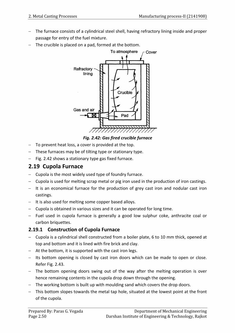
2. Metal Casting Processes Manufacturing process-II (2141908)
Prepared By: Paras G. Vegada Department of Mechanical Engineering Page 2.50 Darshan Institute of Engineering & Technology, Rajkot
− The furnace consists of a cylindrical steel shell, having refractory lining inside and proper passage for entry of the fuel mixture.
− The crucible is placed on a pad, formed at the bottom.
Fig. 2.42: Gas fired crucible furnace
− To prevent heat loss, a cover is provided at the top. − These furnaces may be of tilting type or stationary type. − Fig. 2.42 shows a stationary type gas fixed furnace.
2.19 Cupola Furnace − Cupola is the most widely used type of foundry furnace. − Cupola is used for melting scrap metal or pig iron used in the production of iron castings. − It is an economical furnace for the production of grey cast iron and nodular cast iron
castings. − It is also used for melting some copper based alloys. − Cupola is obtained in various sizes and it can be operated for long time. − Fuel used in cupola furnace is generally a good low sulphur coke, anthracite coal or
carbon briquettes. 2.19.1 Construction of Cupola Furnace − Cupola is a cylindrical shell constructed from a boiler plate, 6 to 10 mm thick, opened at
top and bottom and it is lined with fire brick and clay. − At the bottom, it is supported with the cast iron legs. − Its bottom opening is closed by cast iron doors which can be made to open or close.
Refer Fig. 2.43. − The bottom opening doors swing out of the way after the melting operation is over
hence remaining contents in the cupola drop down through the opening. − The working bottom is built up with moulding sand which covers the drop doors. − This bottom slopes towards the metal tap hole, situated at the lowest point at the front
of the cupola.

Manufacturing process-II (2141908) 2. Metal Casting Processes
Department of Mechanical Engineering Prepared By: Paras G. Vegada Darshan Institute of Engineering & Technology, Rajkot Page 2.51
− Tuyeres are the openings through which air under pressure is forced into the cupola. − Air from the suitable blower, comes through the blast pipe and enters a chamber called
as wind box.
Fig. 2.43: Cupola furnace

2. Metal Casting Processes Manufacturing process-II (2141908)
Prepared By: Paras G. Vegada Department of Mechanical Engineering Page 2.52 Darshan Institute of Engineering & Technology, Rajkot
− The wind box completely encircles the cupola and its purpose is to supply air evenly to all tuyeres.
− Cupolas up to 75 mm diameter may have 3 to 4 tuyeres, whereas large cupolas are fitted with 8 to 10 or more number of tuyeres.
− Tuyere is provided at a height between 0.6 to 1.2 m above the working bottom and extends through the shell and refractory wall to the combustion zone.
− Tuyeres having dimensions of 50 x 150 mm or 100 x 300 mm. − A cupola using 10: 1 ratio of iron to coke, consumes 800-950 m3 of air to melt one tone
of iron. − A slag is located at a level of about 250 mm below the centre of the tuyeres. − Slag being lighter, floats over the metal and removed through the slag hole. − There is a tap hole from where the molten metal is taken out to pour into the mould. − Cupola is also provided with a charging platform and charging door at a suitable height
to feed the charge in cupola. − The height of cupola is generally 6 metres. 2.19.2 Cupola Operation − During operation of cupola following steps are involved : a. Preparation of cupola : − The bottom door is dropped to open. − The contents in the cupola left from the previous melting operation are dumped under
the furnace and removed. − Slag, coke and iron, sticking to the walls of the furnace, are chipped off. − Damaged firebricks are replaced by new ones. − Damaged furnace refractory lining is patched and repaired. − Foundry Technology − Eroded· refractory lining at the combustion zone is filled with refractory patching
mixture. − Patching mixture consists of granister or silica and fireclay. − For original lining, cupola block is used. − Once the furnace lining is reconditioned, the bottom opening door is closed. − Then a sand bottom is prepared. − A layer of 10 mm thick tempered sand slopping towards the tap hole is rammed over the
bottom. − A slope is provided for better flow of molten metal. b. Lighting the fire : − Cupola is fired three hours before the molten metal is poured into the moulds. − For starting the cupola, dry and soft wooden pieces are placed on the rammed sand bed. − Coke is placed over the wooden pieces and the wooden pieces are ignited. − Air required for the combustion of coke enters from the tuyeres.

Manufacturing process-II (2141908) 2. Metal Casting Processes
Department of Mechanical Engineering Prepared By: Paras G. Vegada Darshan Institute of Engineering & Technology, Rajkot Page 2.53
− When initial coke is burning well, an additional amount of coke is added to thedesired height.
c. Charging of cupola : − After igniting the coke bed properly, the cupola is charged from the charging door, by
using alternate layers of limestone, iron and coke up to the level of charging door. − Flux is a substance which aids in forming slag to remove impurities and retards iron
oxidation, lowering the melting point of the slag and increasing its fluidity. − The ratio of metal to fuel by weight ranges from 4: 1 to 12: 1. − Metal charge may consist of 30 % pig iron, 30 % cast iron scrap, about 10 % steel scrap
and about 30 % returns i.e. sprue, gates, risers, etc. − Charging should be completed 45 minutes to 1 hour, before the air blast is turned on. d. Melting : − After charging is over, it is kept as such for about 20 to 50 minutes so that the charge is
heated up with natural draft. − During soaking period, blowers are not started. − At the end of soaking period, the blast is turned on and the coke becomes fairly hot to
melt the metal charge. − The melting process starts about 10 minutes after blast is started. − Molten metal will appear at the hole . − During this period, tap and slag holes are closed with a thin mixture of moulding sand
bolt. − Molten iron is allowed to collect for about 5 minutes. e. Slagging and metal tapping : − After enough molten metal has been collected, the slag hole is opened and slag is
removed. − The bolt inserted in the tap hole is knocked out and molten metal is taken out. − As air blast continues, melting progresses and molten iron is tapped. − The tap hole is sealed with a conical clay plug (bolt), as soon as the slag appears in the
tap hole. − Repeat the slagging and tapping, till all the metal is tapped. − As soon as heating is finished, charging is stopped and the blast is shut off. − Bottom doors are dropped, allowing them to fall on the floor. − The water is sprayed on the remains and removed from underneath of the cupola. 2.19.3 Zones in Cupola − The various zone of cupola are marked in Fig. 2.43 and they are discussed as follows : a. Well: − It is a sort of well of molten metal. − It is situated between the tapered rammed sand bottom and the bottom of the tuyeres. b. Combustion or oxidation zone: − This zone is situated 15 to 30 mm above the top of the tuyeres.

2. Metal Casting Processes Manufacturing process-II (2141908)
Prepared By: Paras G. Vegada Department of Mechanical Engineering Page 2.54 Darshan Institute of Engineering & Technology, Rajkot
− In this zone, as combustion is carried out, all the oxygen in the air is consumed here. − Therefore, a lot of heat is liberated and supplied from here to other zones. − The chemical reactions that take place in this zone are :
( )( )
( )
2 2
2 2
2 2
C + 0 from air C0 +Heat
2Mn + 0 from air 7 2Mn0 +Heat
Si + 0 from air 7
Si0 +Heat
→
→
→
− The temperature of this zone varies from 1540°C to 1840°C. c. Reduction zone : − This zone is also called as protection zone. − It is located above the combustion zone to the top of the coke bed. − This zone has reducing atmosphere and thus protects the metal from oxidation. − An endothermic reaction takes place in this one i.e.
2 2 C0 + C (cock) 2C0 - Heat→
− This reduces the heat in the reducing zone and temperature drops up to 1200 °C. d. Melting zone: − It starts from the first layer of metal charge above the coke bed and extends up to a
height of 90 cm. − Metal charge melts in this zone and trickles down through the coke bed to the well zone. − The temperature in this zone is about 1600°C. − Following reaction takes place in this zone.
3 23Fe + 2CO 7 Fe C + C0→
e. Preheating zone : − This zone starts from above the melting zone and extends upto the bottom of the
charging door. − This zone contains cupola charge as alternate layers of coke, limestone and metal. − Gases like C02, CO and N2 rising upwards from combustion and reduction zones,
preheat the cupola charge to about 1150°C. − Thus, preheated charge gradually moves down in the melting zone. f. Stack zone : − It extends from above the preheating zone to where the cupola steel ends and spark
arrester is attached. − Hot gases from cupola pass through this zone and escape to the atmosphere 2.19.4 Advantages and Limitations of Cupola Advantages: − Its design is simple. − Its initial cost is low as compared to other furnaces of same capacity. − It is economical in operation and maintenance. − Less floor space is required as compared to the other furnaces. − It can be continuously operated for long time.

Manufacturing process-II (2141908) 2. Metal Casting Processes
Department of Mechanical Engineering Prepared By: Paras G. Vegada Darshan Institute of Engineering & Technology, Rajkot Page 2.55
− It is simple to operate and can be maintained in good condition. Limitations: − Close temperature control cannot be maintained. − As molten metal and coke come in contact with each other, certain elements are lost
while others are picked up, this changes the final analysis of molten metal. 2.19.5 Electric Arc Furnace − Originally, the electric furnace was used for the manufacturing of small amount of high-
grade tool steels and alloy steels. − Modem electric furnaces produce a wide range of steels and no longer are considered
suitable only for making a limited range of high quality steels of special compositions. − There are two main types of electric furnaces which are as follows :
o Direct arc furnace o induction furnace
2.19.5.1 Direct Arc Furnace − Electric arc furnace is constructed in the shape of metal shell that is lined with a
refractory material. Refer Fig. 2.54.
Fig. 2.54 : Direct arc furnace
− Usually three phase electric current is used and three large graphite electrodes extend downwards through holes in the roof.
− The electrodes are moved close to the metal charge to produce an electric arc which, into, develops sufficient heat to melt the metal.
− The electrodes become shorter as the intense arc continues; therefore, as the melting progresses in the furnace, the electrodes are slowly moved down automatically to maintain a continuous arc.

2. Metal Casting Processes Manufacturing process-II (2141908)
Prepared By: Paras G. Vegada Department of Mechanical Engineering Page 2.56 Darshan Institute of Engineering & Technology, Rajkot
Operation: − The interior of the furnace is preheated before placing the metal charge into the
furnace. − The furnace is charged either by swinging over the roof or through the charging door. − After placing the cold charge on the hearth of the furnace, electric arc is drawn between
the electrodes and metal surface by lowering the electrodes down till the current jumps between the electrodes and charge surface.
− This arc gap is regulated by automatic controls which raise or lowers the electrodes and maintain desired arc gap.
− This arc produces a temperature of 11,000° F (approximately) and melts the metal scrap. − Before pouring the liquid metal into the ladle, the furnace is tilted backward and the slag
is poured off from the charging door. − After that, the furnace is tilted forward and the molten metal is taken off into the ladles. Advantages: − Unlike crucible furnaces, direct arc furnace undertakes a definite metal refining
sequence. − Analysis of melt can be kept to accurate limits. − Efficiency of direct arc furnace is about 70 %. − It is not difficult to control the furnace atmosphere above the molten metal. − It can make steel directly from pig iron and steel scrap. Disadvantages: − Cost of heating is higher than crucible furnaces. − Electricity consumption of the furnace is high . − Controlling of electric arc is difficult. Applications: − Generally, high quality carbon steels and alloy steels in bulk are made. 2.19.5.2 Induction Furnace − The furnace has a steel jacket that is encircled by a coil through which a high frequency
electric current is passed. Refer Fig. 2.45. − The current in this coil develops an intense heat in the metal charge. − The water cooled copper coil acts as primary coil supplied by high frequency current of
about 2000 cycles. − By induction, secondary currents called eddy currents are produced in the metal charge
in the steel jacket. − These currents flow due to the potential difference between the various parts of the
charge and the resistance of the metal causes current losses which are converted into heat energy for melting the charge.
− The furnace is generally made of tilting type mounted on two pedestals. − The capacity range is up to 15 tons.

Manufacturing process-II (2141908) 2. Metal Casting Processes
Department of Mechanical Engineering Prepared By: Paras G. Vegada Darshan Institute of Engineering & Technology, Rajkot Page 2.57
Fig. 2.45: induction furnace
− The current carried by the coil may range from 10,000 c.p.s. up to 50,000 c.p.s. − These furnaces are used to melt comparatively small charges of cast iron and nonferrous
Metals − Metal temperature in high frequency furnaces may be upto 1760 °C. Advantages: − There is possibility of producing a great variety of products. − Cold charge can be used. − No metal contamination by electrodes or fuel. − Rate of energy input can be readily controlled. − Furnace atmosphere can be easily controlled. − Additions of elements like nickel, chromium, cobalt, tungsten, vanadium, etc. can be
easily made. Disadvantages: − The initial cost of the furnace and its auxiliary equipment is high. − Due to the high speed of the process, there is little time available for analysing the melt
composition. Hence, the metal charge should. Be carefully selected. Applications: − It is very useful for melting alloy steel and high quality steel in small quantity. 2.20 Moulding Machines − Moulding machines are used for high production of sand casting. − They are designed to do much of the work previously done by hand, thus eliminating
most of the labour work. − A moulding machine is also defined as a device which uses large number of correlated
parts and mechanisms, transmits various forces and motions in the required directions so as to help in the sand preparation.

2. Metal Casting Processes Manufacturing process-II (2141908)
Prepared By: Paras G. Vegada Department of Mechanical Engineering Page 2.58 Darshan Institute of Engineering & Technology, Rajkot
− The main functions of moulding machines are : o Ramming of moulding sand. o Rolling over or inverting the mould through 180°. o Rapping of pattern. o Removing the pattern from the mould.
− Following are the types of moulding machines:
2.20.1 Squeeze Moulding Machine − A squeeze moulding machine is very useful for shallow patterns. − To compress the sand above and around the pattern a squeezer, squeeze head plate or
presser board is used. Refer Fig. 2.46(a).
a. b.
Fig. 2.46: Squeezing machine − For squeezing action, the squeeze piston may be forced upward, pushing the flask up
against the squeezer or presser board, then the presser board being forced in the flask. − The sand is rammed harder at the back of the mould and softer on the pattern face. − Another type of squeezing machine applies ramming pressure to the sand admitting
compressed air into an enclosure above a rubber diaphragm as shown in Fig. 2.55 (b). − The pressure obtained by the rubber diaphragm is higher than a piston type machine.
2.20.2 Jolt Moulding Machine − A jar or jolt machine consists of a rugged base cylinder and piston which is attached to
the machine table. − To accomplish jolting, a flask fitted with the sand is raised and then allowed to drop by
gravity.
a. Squeeze moulding machines b. Jolt-squeezing machines
c. Jolt moulding machines d. Sand slinger

Manufacturing process-II (2141908) 2. Metal Casting Processes
Department of Mechanical Engineering Prepared By: Paras G. Vegada Darshan Institute of Engineering & Technology, Rajkot Page 2.59
Fig. 2.47: Jolt moulding machine
− The flask rests on the machine table and a sudden jolt is caused when the falling table is stopped by the solid base of the machine.
− Inertia of the sand causes it to pack with greatest density at the deepest portions of the − sand and with progressively less density up to the top where the sand packing will be
negligible. − Depending upon the mould density, the desired number of jolts is used. − Fig. 2.47 shows the jolt moulding machine which is pneumatically operated. − Jolting is accomplished by opening the valve which admits air to raise the jolt piston − When longer edge of the piston reaches the exhaust part in the cylinder walls, the air
escapes which allows the table to fall and strike the base. − Jolting will continue until the valve remains open. 2.20.3 Jolt-squeezing Moulding Machine − Jolt squeeze machine overcomes the drawback of both squeeze machine and jolt
machine. − This machine is mostly used for match plate moulding.

2. Metal Casting Processes Manufacturing process-II (2141908)
Prepared By: Paras G. Vegada Department of Mechanical Engineering Page 2.60 Darshan Institute of Engineering & Technology, Rajkot
Fig. 2.48 : Jolt-squeeze machine
− Sand around the pattern is rammed due to jolting action, while that on the upper side is rammed due to squeezing action. This will result in uniform ramming.
− For providing two separate actions to the machine table, the machine incorporates two separate cylinders and pistons at its bottom whose timings are well adjusted to give the desired effects of jolting and squeezing one after the other.
− Fig. 2.48 shows a jolt-squeeze moulding machine using a match plate pattern 2.20.4 Sand Slinger − This apparatus rams moulding sand by throwing it into the flask at a very high velocity. − Moulding sand is conveyed to the impeller or ramming head. Refer Fig. 2.49. − The impeller having cup shaped vanes rotate at high speed in the head. − It picks up the sand, forms it into wads and throws them downwards into the flask. − Because of the high speed of the impeller, these wads are discharged in what appears to
be a continuous stream of sand.

Manufacturing process-II (2141908) 2. Metal Casting Processes
Department of Mechanical Engineering Prepared By: Paras G. Vegada Darshan Institute of Engineering & Technology, Rajkot Page 2.61
Fig. 2.49: Sand slinger
− The rate of discharging the sand is about 300 to 2000 kg/minute. − Moulding sand is fed by using a bucket elevator and conveyed to the impellers or
ramming head. − The impeller head can be positioned anywhere on the mould by swinging the arm. − Moulds produced on this machine have adequate strength. − These machines are mostly used in large foundries. 2.21 Casting Processes
Following are the various casting processes which are commonly used: a. Sand mould casting b. Plaster mould casting c. Metallic mould casting
I. Permanent mould casting II. Slush casting
III. Pressure die casting d. Centrifugal casting e. Investment casting f. Continuous casting g. C02 - mould casting. h. Ceramic mould casting
2.21.1 Permanent Mould Casting − The process is also called as gravity die-casting. − The main difference between permanent mould casting and sand casting is that, in this
the mould is permanent which is neither destroyed nor remade after each cast.

2. Metal Casting Processes Manufacturing process-II (2141908)
Prepared By: Paras G. Vegada Department of Mechanical Engineering Page 2.62 Darshan Institute of Engineering & Technology, Rajkot
− For making permanent mould, high resistant fine grained alloy, iron and steel are commonly used.
− Pouring in permanent moulds is simply done due to gravity and hence called as gravity die-casting.
Stages in casting: − Fig. 2.50 shows a permanent mould which comprises of several blocks joined together − The mould is first preheated, by using some means, upto a temperature of 400°C. − The mould is followed by the application of a refractory coating on the mould cavity
surfaces, runner and riser, etc.
Fig 2.50: Section showing one half of a permanent mould
− After attaining the mould temperature, the casting is poured. − As the metal begins to solidify, cores are removed; otherwise it may shrink onto the
surface of the metal. − By blowing, the mould is then cleaned, coated with refractory coating, cores are
assembled and closed again for pouring. Advantages: − It is a very fast process. − Moulds pave longer life. − Better surface finish can be obtained. − Less skilled operator is required. − Less floor area is required. Limitations: − Moulds are much costlier. − This method is not suitable for small quantity production. − Shape and weight of the casting is limited. − Gates, runners and risers cannot be shifted. Applications: − Components produced by this method are : − Hydraulic brake cylinders

Manufacturing process-II (2141908) 2. Metal Casting Processes
Department of Mechanical Engineering Prepared By: Paras G. Vegada Darshan Institute of Engineering & Technology, Rajkot Page 2.63
− Carburetor bodies − Washing machine gears − Oil pump bodies − Aircraft and missile casting, etc. Slush Casting − It is basically a permanent mould casting process. − It is used for producing hollow casting without using cores. − It is mostly preferred for producing such articles, where accuracy is not required but the
outer surface should have ornamental appearance. − Molten metal is poured into the mould, which is turned over immediately, so that the
metal remaining as liquid can run out. − The thickness of solidified shell depends upon the chilling effect from the mould and the
duration for which the metal is allowed to remain in the mould before turning over. − The metals used for such articles are lead, zinc and various low melting alloys. 2.21.2 Pressure Die-casting − In pressure die-casting molten metal is poured by pressure into a metal mould known as
die. − Because the metal solidifies under pressure, the casting confirms to the die cavity in
shape and surface finish. − The pressure is generally obtained with the help of compressed air or hydraulically. − The pressure varies from 70 to 5000 kg/cm2 − The main types of die-casting machines are :
a. Hot chamber die-casting b. Cold chamber die-casting − The principle difference between the two methods is determined by the location of the
melting pot. − In the hot chamber method, a melting pot is included with the machine and the injection
cylinder is immersed in the molten metal at all time. − The injection cylinder is operated by either hydraulic or air pressure, which forces the
metal into the dies to form a casting. − Whereas, cold chamber machine consists of separate melting furnace and metal is
introduced into injection cylinder by hand or mechanical means. a. Hot chamber Die-casting: − In this method metal is forced into the mould and pressure is maintained during
solidification either by a plunger or by compressed air. − Fig. 2.51 shows the main parts of hot chamber machine. − The plunger acts inside a cylinder formed at one end of the goose neck type casting
submerged in the molten metal. − Near the top of the cylinder, for entry of molten metal, a port is provided. − When the bottom of the plunger is above the port, at that time the cylinder is connected
to the melting pot through this port.

2. Metal Casting Processes Manufacturing process-II (2141908)
Prepared By: Paras G. Vegada Department of Mechanical Engineering Page 2.64 Darshan Institute of Engineering & Technology, Rajkot
− This downward stroke of the plunger closes this port, cuts off the supply of metal and applies pressure on the metal present in the goose-neck to force it into the die cavity through the injecting nozzle.
Fig. 2.51 : Hot chamber die-casting machine
− After sometime, the plunger is raised up, causing the remaining molten metal in the nozzle and channel to fall back into the casting.
− Before the end of upward stroke, the plunger uncovers the port, through which more amount of molten metal enters into the cylinder.
− Then the dies are opened and casting is ejected. − These machines are generally used for producing castings of low melting point metals
like zinc, tin and lead. b. Cold chamber Die-casting: − Fig. 2.52 shows the working principle of cold chamber machine.
Fig. 2.52: Cold chamber die casting machine

Manufacturing process-II (2141908) 2. Metal Casting Processes
Department of Mechanical Engineering Prepared By: Paras G. Vegada Darshan Institute of Engineering & Technology, Rajkot Page 2.65
− The machine consists of separate furnace for melting the metal. − The metal is melted separately in the furnace and transferred to cold chamber by using
small hand ladle. Refer Fig. 2.52 (a). − After closing the die, the molten metal is poured into the horizontal chamber through
the metal inlet. − To force the metal into the die, the plunger is pushed forwards hydraulically. Refer Fig.
2.52 (b). − After solidification, the die is opened and the casting is ejected. − Cold chamber machines are mainly used for making castings in aluminum, brass and
magnesium. − The life of these machines is more, because the melting unit is separated from the
working parts. − But, the life of die is less because the machine involves very high pressure i.e. about200
to 2000 kg/cm2 Advantages of pressure die casting: − High production rates are possible. − Economical for large production quantities. − Close tolerances up to ± 0.076 mm on small parts is possible. − Good surface finish can be obtained. − Thin sections up to 0.5 mm can be cast.· − Limitations of pressure die casting : − Only small parts can be made. − Only non-ferrous alloys and metals can be commercially cast. − Due to high cost of equipment and dies, the process is economical only for mass
production. − Due to entrapped air, the die castings are porous which reduces mechanical properties
of the component. Applications of pressure die casting: − Household equipments like decorative parts, mechanical parts of mixers, fans, vacuum
cleaners, washing machines, can openers; refrigerators, etc. can be made. − Industrial equipments like motor housing, crane parts, motor, rotor fan, impeller wheel,
etc. can be made. − Automotive parts like windshield frames, window channels, bodies of fuel pump and
carburetor, handles, rear view mirror parts, brake shoe (Al), etc. can be made. − Toys like pistols, electric trains, model aircraft, automobiles, etc. can be made. − Other parts like taps, valves, burners, fire alarm system, telephone sets, speakers, − staplers, typewriters, etc. can be mad 2.21.3 Centrifugal Casting − Centrifugal casting is also known as liquid forging. − In this process mould is rotated at high speed and molten metal is poured into it.

2. Metal Casting Processes Manufacturing process-II (2141908)
Prepared By: Paras G. Vegada Department of Mechanical Engineering Page 2.66 Darshan Institute of Engineering & Technology, Rajkot
− Due to the centrifugal force, the molten metal is directed outwards from the centre i.e. towards the inner surface of the mould with high pressure.
− Hence, a uniform thickness of metal is deposited all along the inner surface of the mould, where it solidifies and the impurities being lighter remains nearer to the rotation axis.
− This process produces casting with greater accuracy and better physical properties. − This method is mainly suitable for producing casting of symmetrical shapes. − Centrifugal casting processes can be classified as :
a. True centrifugal casting b. Semi -centrifugal casting c. Centrifuging
a. True centrifugal casting : − An important feature of true centrifugal casting is that, the axis of rotation of the mould
and that of the casting are the same. − Also there is no need of central core for producing central hole. − The axis of rotation· of the mould may be horizontal, vertical or inclined at any suitable
angle. − During the operation, moulding flask is properly rammed with sand to confirm to the
outer contour of the casting to be made. − The flask is then dynamically balanced to reduce undesirable vibrations during the
process. − The finished flask is mounted between the rollers and the mould is rotated slowly. Refer
Fig. 2.53.
Fig. 2.53 : Horizontal true centrifugal casting machine
− The molten metal is poured into the revolving mould. − The centrifugal force throws the metal towards the outer walls. − The amount of the metal poured determines the thickness of the casting. − After pouring is completed; the mould is rotated at its original speed, till it solidifies to
form the required casting.
Manufacturing process-II (2141908) 2. Metal Casting Processes
Department of Mechanical Engineering Prepared By: Paras G. Vegada Darshan Institute of Engineering & Technology, Rajkot Page 2.67
− The outer surface of the mould is water cooled, therefore metal solidifies quickly. − The casting machine is mounted on wheels with pouring ladle which has a long spout
exceeding till the other end of the casting to be made. − This method is used to cast hollow cylindrical objects such as hollow pipes, gun barrels,
liner bushes, etc. b. Semi centrifugal casting: − In semi-centrifugal casting method the mould is completely full of metal as it is spun
about its vertical axis and risers and core may be employed. − Rotational speed for these methods is not as great as for the true centrifugal process. − The molten metal 1s poured through a central sprue. Refer Fig. 2.54.
Fig. 2.54: Semi-centrifugal casting
− As the speed of rotation is low, centrifugal force and pouring pressure produced are low. − The impurities are not collected at the centre. − The moulds used may be of green sand, dry sand, metal or any other suitable material. − A central core is used to form the required inner surface of the casting. − This method is used to produce larger sized symmetrical casting such as discs, pulleys,
gears, sprocket wheels, etc. c. Centrifuging : − In this method several casting cavities are located around the outer portion of a mould
and the metal is fed to these cavities by radial gates from the centre. − The centrifugal force produces sufficient pressure, to force the metal into the cavities. − This method mainly differs from true centrifugal method in that, the axis of rotation and
that of the mould do not coincide with each other. Refer Fig. 2.55.

2. Metal Casting Processes Manufacturing process-II (2141908)
Prepared By: Paras G. Vegada Department of Mechanical Engineering Page 2.68 Darshan Institute of Engineering & Technology, Rajkot
− This method is also called as pressure casting.
Fig. 2.55: Centrifuged casting
− The internal cavities of these castings are irregular in shape and are formed by dry sand cores.
− This method is also used for unsymmetrical objects. − It can produce casting of irregular shapes such as bearing caps or small brackets, etc. 2.21.4 Investment Casting − Investment casting process is also known as lost-wax process. − The term investment refers to a clock or special covering apparel. − In investment casting, the clock is a refractory mould which surrounds the pre coated
wax pattern. − A wax pattern must be made for every casting and gating system also. − A wax pattern is invested by liquid mould material which is latter allowed to be set and
form a hard layer around the pattern. − A mould cavity is then obtained by melting the wax pattern.

Manufacturing process-II (2141908) 2. Metal Casting Processes
Department of Mechanical Engineering Prepared By: Paras G. Vegada Darshan Institute of Engineering & Technology, Rajkot Page 2.69
− The steps in an investment casting process are as follows (Refer Fig. 2.56) :
Fig. 2.56: Steps involved in making investment casting
a. Die making : − A die for casting the wax pattern is made. − These dies can be made by using a metallic master pattern and casting a low melting
point alloy around it. b. Wax patterns and gating systems : − Wax patterns and gating systems are produced from the metal dies by injection. − Wax is injected into the die at a temperature of 70°C to 80°C and at a pressure of 8 to
150 kg/cm2. c. Assembling the wax patterns: − The wax patterns so made are then attached to wax gates and Sprues already made with
the help of heated tool known as hot wire welder.

2. Metal Casting Processes Manufacturing process-II (2141908)
Prepared By: Paras G. Vegada Department of Mechanical Engineering Page 2.70 Darshan Institute of Engineering & Technology, Rajkot
− Assembling fixtures are used to minimize the operation time. d. Pre coating : − The wax assembly is dipped into slurry of a refractory coating material. − Typical slurry consists of 325 mesh silica flour suspended in ethyl silica solution of
suitable viscosity to produce uniform coating. e. Investing : − The coated wax assembly is then invested in the mould. − This is done by inverting the wax assembly on a table, surrounding it with a paper lined
steel flask and pouring the investment moulding mixture around the pattern. − The whole system is then vibrated and then the material settles by gravity and the
mould is then allowed to air-set. f. Wax melting : − The wax is melted out of the hardened mould by heating it in an inverted position at
about 200°C. − Sometimes, the wax may be reused. g. Pouring : − Prepared moulds are first preheated to a suitable temperature between − 540°C to 1 040°C and the metal is gravity poured into the sprue. − Air pressure may then be applied to the sprue with force to fill the mould cavity. h. Cleaning and inspection : − After solidification, the casting is vibrated to separate itself from the investment
material. − The gates, risers, etc. are then chipped off. − The castings are then subjected to sand blasting. − Then they are inspected through the specified inspection method. Advantages: − Better dimensional accuracy with close tolerances can be achieved. − Complicated shapes and complex contours can be easily cut. − Extremely thin sections up to 0.75 mm can be cast. − Surface finish of the casting is very high. − Castings are sound and free from defects. Limitations: − Size of the casting to be made is limited. − Suitable only for small sized casting. − Moulds used are single purpose only. − Cost of investment material is high. − It is a time consuming process. Applications: − Parts for aerospace industry, aircraft engines, frames, fuel systems, etc.

Manufacturing process-II (2141908) 2. Metal Casting Processes
Department of Mechanical Engineering Prepared By: Paras G. Vegada Darshan Institute of Engineering & Technology, Rajkot Page 2.71
− Parts for food and beverage machinery, computers and data processing equipment, machine tools and accessories.
− Nozzles, buckets, blades, etc. for gas turbines. − Costume jewellery can be made. 2.21.5 Continuous Casting − Continuous casting is accomplished by pouring molten metal into one end of a metal
mould, which is open at both the ends, and by keeping it filled always. − The metal at the lower end is cooled so that it solidifies and solid product thus formed is
extracted in a continuous length from the lower end. − Continuous casting is the most commonly used process. Refer Fig. 2.66. − In this, metal in the molten state is transferred from the holding furnace into a special
ladle from where the same is poured onto the top of a bottomless graphite mould of the required shape.
− The molten metal should be slag free and should be poured with minimum turbulence to reduce mould friction.
− At the starting of the process, a dummy bar is placed in the mould upon which the first liquid metal falls.
− The liquid metal gets cooled and is pulled by the pinch rollers along with the dummy bar. − Metal shrinks from the mould walls, which provides a very small gap between the metal
and the mould, thereby reducing the friction between them and permits cast shape to move continuously through the mould.
− Pinch and guide rollers regulate the rate of setting of cast shape and keep proper alignment.
− As the casting passes out of the pinch rollers, it is cut to the required length by using some cutting method.
Advantages: − The process is cheaper than rolling from ingots. − There is no need of rough forming and breakdown rolling operation. − Casting surfaces obtained are better than the static ingots. − Grain size and structure of the casting can be regulated by controlling cooling rates. − Casting is more dense and uniform than individual castings because each portion of the
casting length gets same treatment in the same mould. − Castings obtained by this process have improved quality. − As the process is essentially automatic unit labour cost is low. Applications: − This process can produce any shape of uniform cross-section such as rectangular,
square, hexagonal, gear toothed, etc. either solid or hollow. − Production of blooms, billets, slabs and sheets. − Materials like brass, zinc, copper and its alloys, aluminum and its alloys, alloy steel
maybe cast.
2. Metal Casting Processes Manufacturing process-II (2141908)
Prepared By: Paras G. Vegada Department of Mechanical Engineering Page 2.72 Darshan Institute of Engineering & Technology, Rajkot
Fig. 2.57 : Continuous casting process
2.21.6 Ceramic Mould Casting − Ceramic mould is a variation of the investment mould. − In this mould, slurry composed of refractory sand grains (Powder of zircon, alumina,
fused silica) and ceramic binder is poured into wax pattern. − This results in a thin-wall shell of ceramic over the pattern surfaces.

Manufacturing process-II (2141908) 2. Metal Casting Processes
Department of Mechanical Engineering Prepared By: Paras G. Vegada Darshan Institute of Engineering & Technology, Rajkot Page 2.73
− After this, pattern is baked in a less expensive fire clay and then it is removed from the mould and transferred to an oven for further heating mould.
− For producing castings, then the molten metal is poured into the mould cavity through the sprue.
− In this method, the preheated mould is used during pouring of molten metal which results in elimination of partial filling of moulding.
Advantages: − Castings produced by this method do not require machining. − Casting of intricate objects can be produced by this method. − This method can cast high melting point alloys to accurate dimensions. − Thin sections even for high melting point metals and alloys can be produced by this
method.
2.22 Casting Defects and Remedies − A large number of defects occur in sand casting produced through different methods. − These defects offer a great problem to the foundry industry. − Casting defects are usually not accidents, they occur because some manufacturing steps
are not properly controlled. − A defect may be the result of single cause or a combination of factors. − The factors which are generally responsible for these defects are :
o Design of casting and pattern equipment o Moulding and core making equipment o Mould and core materials o Metal composition o Gating and risering o Melting and pouring, etc.
1. Blow holes: − Blow holes appear as cavities in a casting. − These blows are normally rounded and have smooth walls. − They are not visible from the outside. 2. Porosity : − This defect occurs in the casting in the form of pinhole porosity or gas porosity. − Gas porosity is more pronounced with higher melting temperature and slower
solidification of metal. 3. Shrinkage : − During solidification of metal, there is a volumetric shrinkage. − They may exist on the surface as depression, called as surface shrinkage or with in the
casting called as internal shrinkage. 4. Inclusions : − Any separate non-metallic foreign material present in the cast metal is known as
inclusions.

2. Metal Casting Processes Manufacturing process-II (2141908)
Prepared By: Paras G. Vegada Department of Mechanical Engineering Page 2.74 Darshan Institute of Engineering & Technology, Rajkot
− These inclusions may be in the form of oxides, slags, dirt, sand or gas.
Fig. 2.58: Casting defects
5. Hot tears : − Hot tears are also called as pulls or hot cracks. − They are supposed to be more harmful when present internally. − Their presence is identified by an oxidized surface showing an irregular and ragged
appearance on the fracture. 6. Misrun and cold shuts : − When the molten metal fails to reach all the sections of the mould, certain part of it
remains unfilled. − This result in an incomplete casting, the defect is known as misrun.

Manufacturing process-II (2141908) 2. Metal Casting Processes
Department of Mechanical Engineering Prepared By: Paras G. Vegada Darshan Institute of Engineering & Technology, Rajkot Page 2.75
− When two streams of molten metal approach each other in the mould from opposite directions, a physical contact between them is established.
− But, if they fail to fuse together, then it results in discontinuity between them, which is known as cold shuts.
7. Cuts and washes (scabs) : − The cavities formed on the mould and core surfaces due to erosion are filled by the
molten metal and it appears on the casting surface as an excess metal in the form of ragged parts.
− These spots are called as scabs. 8. Mismatch (Shift) : − Shift is a misalignment between two mating surfaces, leaving a small clearance between
them and changing their location. − It occurs at· the parting surface between two parts of the mould, called as mould shift or
at core prints i.e. the gap between core and core seats are called as core shift. 9. Hard spots : − Hard spots on surfaces are generally developed on iron casting, rich in silicon content,
due to local chilling of those spots by moulding sand. − Due to this, white cast iron is formed at those places and makes them hard. 10. Warpage : − Warpage is an undesirable deformation in the casting which may occur during or after
solidification. − The deformation takes place because of internal stresses developed in the casting due to
differential solidification in various sections.
2.23 Metals for Casting − Most of the commercial castings are made of alloys rather than pure metals. It is
because, the alloys are easier to cast and the properties of resulting product are better. − Casting alloys can be classified as follows : 1. Ferrous casting alloys
o Cast iron o Steel − 2. Non-ferrous casting alloys
o Aluminium alloys o Magnesium alloys o Copper alloys o Tin based alloys
o Zinc alloys o Nickel alloys o Titanium alloys

Department of Mechanical Engineering Prepared By: Paras G. Vegada Darshan Institute of Engineering & Technology, Rajkot Page 2.76
Ferrous casting alloys (Cast iron): − Cast iron is the most important of all the casting alloys. The tonnage of cast iron
castings is several times than the castings of other metals. − The different types of cast iron are gray cast iron, white cast iron, malleable cast
iron, nodular cast iron, etc. − The pouring temperature for cast iron is about 1400 °C. Ferrous casting alloys (Steel): − As the mechanical properties of steel are better than the others, it is .an important
engineering material. Also the capability to create complex geometry makes casting an easier process.
− The melting point of steel is higher than the other casting metals. − The solidification range for steel begins at just under 1540 °C. It means, the pouring
temperature for steel is very high i.e. about 1650 °C. − At these high temperatures, steel is chemically very reactive. It readily oxidizes, so
special treatments are used during melting and pouring. Non-ferrous casting alloys (Aluminium alloys): − Generally aluminum alloys are considered to be very cast able. − The melting point of aluminum is 660°c hence pouring temperatures for aluminum
casting alloys are low as compared to steel and cast iron. − The properties like light weight, wide range of strength, ease of machining, etc.
Makes aluminum more attractive for casting. Non-ferrous casting alloys (Magnesium alloys): − These are the lightest of all casting metals. − The properties like high corrosion resistance, high strength to weight ratio, high
stiffness to weight ratio, light weight, etc. makes it attractive for casting. Non-ferrous casting alloys (Copper alloys): − It includes brass, bronze, aluminum bronze, etc. − It has properties like high corrosion resistance, better appearance, good bearing
qualities, etc. but its high cost restricts its use. Non-ferrous casting alloys (Tin-based and zinc alloys): − They have the lowest melting point of the casting metals. Also they are easy to cast. − They have good corrosion resistance but low mechanical strength which restricts
their applications. Non-ferrous casting alloys (Nickel and titanium alloys): − They have good hot strength and corrosion resistance which makes them suitable
for high temperature applications. − They have high melting point and low fluidity hence they are not easy to cast.
2.24 Salvaging of Casting − Salvaging of casting refers to the act of saving the defective castings and utilizes
them by repairing.
Manufacturing process-II (2141908) 2. Metal Casting Processes
Department of Mechanical Engineering Prepared By: Paras G. Vegada Darshan Institute of Engineering & Technology, Rajkot Page 2.77
− In the mass production of light casting, the salvaging of casting is not necessary and hence avoided.
− It is because the defective light castings can be scrapped and replaced due to cost and inconvenience of salvaging.
− In the production of large and complex cast parts, salvaging is preferred over scrapping and replacing the defective cast part.
− These large castings are made serviceable by repairing due to the higher cost of replacement of defective casting.
− Also, salvaging is done to restore properties and service performance of the defective castings and to improve casting appearance as in case of standard cast component. Factors affecting salvage of casting
− Following are the various factors related to casting that affects salvaging : − Composition of material used for casting − Size and shape of casting component − Relative cost of repairing of casting and new casting component − Performance of product after salvaging − Quality requirements − Availability of equipments and methods, etc. 2.24.1 Salvaging Techniques
Following are the various salvaging techniques employed for repairing defective castings: a. Welding b. Brazing, Braze welding, Soldering c. Burning on d. Patches and plugs e. Caulking and impregnation
a. Welding: − It is the most commonly used method for salvaging. − Welding technique achieves true metallurgical union between casting and filler metal,
therefore it is preferred over other salvaging techniques. − Most commonly used welding methods are TIG welding, MIG welding, shielded metal
arc welding and gas welding. − Before carrying out welding repairs, the component must be prepared by chipping,
grinding or by filling cracks. − The defective casting is then filled with electrode material during welding. b. Soldering, brazing and braze welding : − These processes use filler material as non-ferrous metals. − Filler material fills the defects and casting is repaired. Generally, it is done below the
melting point of casting.

2. Metal Casting Processes Manufacturing process-II (2141908)
Prepared By: Paras G. Vegada Department of Mechanical Engineering Page 2.78 Darshan Institute of Engineering & Technology, Rajkot
c. Burning on : − Generally it is a welding process but carried out with the help of moulder. − A cavity is prepared at the place of defect in the casting. A sand mould is built up to
surround the cavity. − The molten metal is then poured until the mould is filled. This method is used for
large castings. d. Patches and plugs − The defective place on the casting is drilled out and a patch or plug is inserted into
the drilled hole. − This patch or plug is then finished by various methods. e. Caulking and impregnation − Caulking is filling the cracks in order to make watertight or airtight tanks or windows. − It is done by hand or pneumatic hammering. The leaks are closed by plastic
deformation. − Caulking is useful for minor leaks whereas impregnation is used to seal widespread
porosity.

Department of Mechanical Engineering Prepared By: Disha V. Gondiya Darshan Institute of Engineering & Technology, Rajkot Page 3.1
3 METAL JOINING PROCESSES
Course Contents
3.1 Welding
3.2 Principle of soldering,
Brazing & Adhesive bonding
3.3 Types of welding
3.4 Classification of welding
3.5 Gas welding
3.6 Position of welding
3.7 Gas welding technique
3.8 Welding equipment
3.9 Arc welding
3.10 Electrodes for arc welding
3.11 Resistance welding
3.12 Thermit welding
3.13 Solid state welding
3.14 Electron beam welding
3.15 Laser beam welding
3.16 Defects in welding

3. Metal Joining Processes Manufacturing Processes - II (2141908)
Prepared By: Disha V. Gondiya Department of Mechanical Engineering Page 3.2 Darshan Institute of Engineering & Technology, Rajkot
3.1 Welding Welding is a process of joining similar metals by application of heat with or without
application of pressure and additional of filler material. Welding joints different metals/alloys. In welding heat is supplied either electrically or
by means of a gas torch. Advantages
Welding is more economical and is much faster process as compared to other processes
(riveting, bolting, casting etc.)
Welding, if properly controlled results permanent joints having strength equal
orsometimes more than base metal.
Large number of metals and alloys both similar and dissimilar can be joined bywelding.
General welding equipment is not very costly.
Portable welding equipment can be easily made available.
Welding permits considerable freedom in design.
Welding can join welding jobs through spots, as continuous pressure tight seams,end-
to-end and in a number of other configurations.
Welding can also be mechanized.
Disadvantages
It results in residual stresses and distortion of the work pieces.
Welded joint needs stress relieving and heat treatment.
Welding gives out harmful radiations (light), fumes and spatter.
Jigs, and fixtures may also be needed to hold and position the parts to be welded
Edges preparation of the welding jobs are required before welding
Skilled welder is required for production of good welding
Heat during welding produces metallurgical changes as the structure of the weldedjoint
is not same as that of the parent metal.
3.2 Principle of soldering, brazing and adhesive bonding
3.2.1 Brazing
Brazing is a metal joining process whereby a filler metal is heated above melting point
and distributed between two or more close fitting parts by capillary action. In brazing, metallic parts are joined by joined by a non-ferrous filler metal or alloy.
Brazing involves the melting of comparatively low melting point filler material against
the base metal pieces to be joined while they are clean and free from oxides, oil grease,
etc.
The molten filler material
1. Wets the base metal surfaces
2. Spreads along the joint by capillary action
3. Adheres and solidifies to from the brazed joint.
Brazing gives much stronger joint compare to soldering.

Manufacturing processes – II (2141908) 3. Metal Joining Processes
Department of Mechanical Engineering Prepared By: Disha V. Gondiya Darshan Institute of Engineering & Technology, Rajkot Page 3.3
Filler material used in this processes are generally two types
1. Copper based alloy
2. Silver based alloy
The parts to be joined by brazing are carefully cleaned, the flux applied and the parts
clamped in position for joining.Borax is generally used as flux.
The parts to be joined are to be heated to a temperature above the melting point of the
spelter, and molten spelter is allowed to flow by capillary action into the space between
the parts and to cool slowly.
Advantages
In brazing dissimilar metals or non-metals can be joined.
Complicated component can also be brazed at low cost.
It is suitable for mass production.
Brazing produces clean joint.
Brazing does not melt the base metal which allows much close control over the
tolerances.
Disadvantages
Strength of brazed joints can be damaged under high service temperature.
Strength of the brazed joints is less compare to welded joints.
Filler metals used in this process are costly.
The joint color is different than that of base metal which creates an aesthetic
disadvantage.
Application
Brazing is applicable to cast and wrought iron, steel, Cu, Al, Mg and their alloys.
3.2.2 Soldering
Soldering is a method of joining two or more pieces of metal by means of a fusible alloy
or metal, called solder, applied in molten state.
Solders are essentially alloys of lead and tin. To improve the mechanical properties and
temperature resistance, solders are added to other alloying elements such as zinc,
cadmium and silver in various proportions. Solders are essentially alloys of lead and tin.
To improve the mechanical properties and temperature resistance, solders are added to
other alloying elements such as zinc, cadmiumand silver in various proportions.
Solvent cleaning, acid pickling and even mechanical cleaning are applied before
soldering.
Advantages
By soldering various dissimilar metals can be joined.
It is simple and low cost method.
Work piece with different thickness can be joined.
The joined formed in the soldering, do not require machining.
Soldering is a low temperature process; hence there is no change in the properties of
metals.

3. Metal Joining Processes Manufacturing Processes - II (2141908)
Prepared By: Disha V. Gondiya Department of Mechanical Engineering Page 3.4 Darshan Institute of Engineering & Technology, Rajkot
Disadvantages
The soldered joints are not suitable for high temperature service because of the low
melting temperatures of the filler metals used.
The soldering joints also need to be cleaned meticulously to provide chemically clean
surfaces to obtain a proper bond.
Corrosion resistance of solder joint is less.
3.2.3 Adhesive bonding
Adhesive bonding is the process of joining materials by using adhesives.
In this processes surface preparation is done so that the adhesive applied on the surface
which is free from foreign particles.
A low viscosity primer is then applied in one or more coats by spraying and brushing.
After primer is dried, the adhesive is applied.
After that assembly of adhesive coated components is done.
Application
Assembly of electronic components
Joints in wire
Joints in sheet metal objects like food cans.
3.3 Types of welding
There are two types of welding: - 1) Plastic welding 2) Fusion welding
3.3.1 Plastic welding (Pressure welding)
In this type of welding the piece of metal to be joined are heated to a plastic state and
then forged together by external pressure.
This processes is used in forge welding, resistance welding,
3.3.2 Fusion welding (Non-pressure)
The fusion of metal takes place by means of heat. The heat may be generated either
from combustion of gases, electric arc, electric resistance or by chemical reaction. In this method filler material is required during the process like arc welding, gas welding.
3.4Classification of welding
1. Gas welding
a. Oxy-acetylene
b. Air-acetylene
c. Oxy-hydrogen
2. Arc welding
a. Carbon arc welding d. Metal arc g. Gas-metal arc(MIG)
b. Plasma arc welding e. Electro-slag h. Gas-tungsten arc (TIG)
c. Submerged arc welding f. Flux-cored i. Atomic-hydrogen arc

Manufacturing processes – II (2141908) 3. Metal Joining Processes
Department of Mechanical Engineering Prepared By: Disha V. Gondiya Darshan Institute of Engineering & Technology, Rajkot Page 3.5
3. Resistance welding
a. Butt c. Spot e. Seam
b. Projection d. Percussion
4. Thermit welding
5. Solid state welding
a. Friction c. Ultrasonic
b. Explosive d. Diffusion
6. Newer welding (Radiant Energy welding)
a. Electro-beam
b. Laser
3.5 Gas welding
A fusion welding process which joins metals, using the heat of combustion of an oxygen
/air and fuel gas (i.e. acetylene, hydrogen) mixture is usually referred as ‘gas welding’.
Figure 3.1 Gas welding
The intense heat (flame) thus produced melts and fuses together the edges of the parts
to be welded, generally with the addition of a filler metal.
The fuel gas generally employed is acetylene; however gases other than acetylene can
also be used though with lower flame temperature
Oxy-acetylene flame is themost versatile and hottest of all the flames produced by the
combination of oxygen and otherfuel gases.
3.5.1 Oxy-acetylene welding
In this process, acetylene is mixed with oxygen in correct proportions in the welding torch and ignited
The flame resulting at the tip of the torch is sufficiently hot to melt and join the parent metal.
The oxy-acetylene flame reaches a temperature of about 3300°C and thus can melt most of the ferrous and non-ferrous metals in common use.
A filler metal rod or welding rod is generally added to the molten metal pool to build up
the seam slightly for greater strength.

3. Metal Joining Processes Manufacturing Processes - II (2141908)
Prepared By: Disha V. Gondiya Department of Mechanical Engineering Page 3.6 Darshan Institute of Engineering & Technology, Rajkot
3.5.2 Types of flame
Neutral flame
A neutral flame results when approximately equal volumes of oxygen and acetylene are
mixedin the welding torch and burnt at the torch tip.
The temperature of the neutral flame is ofthe order of about 5900°F (3260°C).
It has a clear, well defined inner cone, indicating that thecombustion is complete.
The inner cone is light blue in color. It is surrounded by an outerflame envelope,
produced by the combination of oxygen in the air and superheated carbonmonoxide and
hydrogen gases from the inner cone.
This envelope is usually a much darkerblue than the inner cone.
A neutral flame is named so because it affects no chemical changeon the molten metal
and, therefore will not oxidize or carburize the metal. The neutral flameis commonly
used for the welding of mild steel, stainless steel, cast Iron, copper, and aluminium.
Figure 3.2 Oxy-Acetylene gas flames
Carburizing flame
The carburizing or reducing flame has excess of acetylene and can be recognized
byacetylene feather, which exists between the inner cone and the outer envelope.
The outerflame envelope is longer than that of the neutral flame and is usually much
brighter in color.
With iron and steel, carburizing flame produces very hard, brittle substance known as
ironcarbide.
A reducing flame may be distinguished from carburizing flame by the fact that
acarburizing flame contains more acetylene than a reducing flame.
A reducing flame has anapproximate temperature of 3038°C.
A carburizing-flame is used in the welding of lead and forcarburizing (surface hardening)
purpose.
A reducing flame, on the other hand, does notcarburize the metal; rather it ensures the
absence of the oxidizing condition.

Manufacturing processes – II (2141908) 3. Metal Joining Processes
Department of Mechanical Engineering Prepared By: Disha V. Gondiya Darshan Institute of Engineering & Technology, Rajkot Page 3.7
It is used forwelding with low alloy steel rods and for welding those metals, (e.g., non-
ferrous) that do nottend to absorb carbon.
This flame is very well used for welding high carbon steel.
Oxidizing flame
The oxidizing flame has an excess of oxygen over the acetylene.
An oxidizing flame canbe recognized by the small cone, which is shorter, much bluer in
color and more pointed thanthat of the neutral flame.
The outer flame envelope is much shorter and tends to fan out atthe end. Such a flame
makes a loud roaring sound.
It is the hottest flame (temperature ashigh as 6300°F) produced by any oxy-fuel gas
source.
But the excess oxygen especially at high temperatures tends to combine with many
metals to form hard, brittle, low strength oxides.
Moreover, an excess of oxygen causes the weld bead and the surrounding area to have
ascummy or dirty appearance.
For these reasons, an oxidizing flame is of limited use inwelding. It is not used in the
welding of steel.
A slightly oxidizing flame is helpful whenwelding (i) Copper-base metals (ii) Zinc-base
metals and (iii) A few types of ferrous metals suchas manganese steel and cast iron.
The oxidizing atmosphere in these cases, create a basemetaloxide that protects the base
metal.
3.6 Position of welding
Horizontal welding
In horizontal position, the plane of the work piece is vertical and the deposited weld
headis horizontal.
The metal deposition rate in horizontal welding is next to that achieved in flator down
hand welding position.
This position of welding is most commonly used in weldingvessels and reservoirs
Figure 3.3 Position of welding
(a)Horizontal welding (b) Vertical welding (c) Inclined welding (d) Horizontal welding in vertical
direction (e) overhead welding

3. Metal Joining Processes Manufacturing Processes - II (2141908)
Prepared By: Disha V. Gondiya Department of Mechanical Engineering Page 3.8 Darshan Institute of Engineering & Technology, Rajkot
Vertical welding
In vertical position, the plane of the work piece is vertical and the weld is deposited
upon avertical surface.
It is difficult to produce satisfactory welds in this position due to the effectof the force of
gravity on the molten metal.
The welder must constantly control the metalso that it does not run or drop from the
weld.
Vertical welding may be of two types’ viz., vertical-up and vertical-down. Vertical-up
welding is preferred when strength is the majorconsideration.
The vertical-down welding is used for a sealing operation and for welding sheetmetal.
Overhead welding
The overhead position is probably even more difficult to weld than the vertical position.
Here the pull of gravity against the molten metal is much greater.
The force of the flameagainst the weld serves to counteract the pull of gravity. In
overhead position, the plane ofthe work piece is horizontal.
But the welding is carried out from the underside. The electrodeis held with its welding
end upward.
It is a good practice to use very short arc and basic coatedelectrodes for overhead
welding.
3.7 Techniques of welding
3.7.1 Leftward (Forward) welding technique
In this technique, the welder holds welding torch in his right hand and filler rod in left
hand.
The welding flame is directed from right to left as shown in figure
The welding torch should be given a small sideways movement and the filler rod should
be moved steadily without sideways movement.
The welding torch held at 60 to 70 to the weld plane and the filler rod at 30 to 40.
3.7.2 Rightward (Backward) welding technique
In this technique, the welder holds welding torch in his left hand and filler rod in right
hand.
The welding flame is directed from left right to as shown in figure
The welding torch has no lateral movement.
The welding torch held at 40 to 50 to the weld plane and the filler rod at 30 to 40.

Manufacturing processes – II (2141908) 3. Metal Joining Processes
Department of Mechanical Engineering Prepared By: Disha V. Gondiya Darshan Institute of Engineering & Technology, Rajkot Page 3.9
Figure 3.4 Left ward welding Figure 3.5 Right ward welding
3.7.3 Vertical welding
Figure 3.6 vertical welding
The method is more advantageous for plate thickness of 6 mm and above.
In this, the welder starts at the bottom of the welded joint and gives oscillating
movement to the welding torch which points slightly upwards.
It can be done by one or two operator.
In case of single operator technique, the angle between the welding torch and plate
increases as the plate thickness increases.
3.8 Welding Equipment Cylinder

3. Metal Joining Processes Manufacturing Processes - II (2141908)
Prepared By: Disha V. Gondiya Department of Mechanical Engineering Page 3.10 Darshan Institute of Engineering & Technology, Rajkot
Acetylene and oxygen gas is stored in compressed gas cylinders. These gas
cylindersdiffer widely in capacity, design and colour code.
However, in most of the countries, thestandard size of these cylinders is 6 to 7 m3 and is
painted black for oxygen and maroon foracetylene.
An acetylene cylinder is filled with some absorptive material, which is saturatedwith a
chemical solvent acetone.
Acetone has the ability to absorb a large volume of acetyleneand release it as the
pressure falls. If large quantities of acetylene gas are being consumed,it is much cheaper
to generate the gas at the place of use with the help of acetylene gasgenerators.
Acetylene gas is generated by carbide-to-water method.
Oxygen gas cylinders are usually equipped with about 40 liters of oxygen at a pressureof
about 154 Kgf/cm2 at 21°C. To provide against dangerously excessive pressure, such
ascould occur if the cylinders were exposed to fire, every valve has a safety device to
releasethe oxygen before there is any danger of rupturing the cylinders.
Fragile discs and fusibleplugs are usually provided in the cylinders valves in case it is
subjected to danger.
Figure 3.7 Oxy-Acetylene welding set
Gas pressure regulators
Gas pressure regulators are employed for regulating the supply of acetylene and
oxygengas from cylinders.
A pressure regulator is connected between the cylinder and hose leadingto welding
torch.
The cylinder and hose connections have left-handed threads on the acetyleneregulator
while these are right handed on the oxygen regulator.

Manufacturing processes – II (2141908) 3. Metal Joining Processes
Department of Mechanical Engineering Prepared By: Disha V. Gondiya Darshan Institute of Engineering & Technology, Rajkot Page 3.11
A pressure regulator is fittedwith two pressure gauges, one for indication of the gas
pressure in the cylinder and the otherfor indication of the reduced pressure at which the
gas is going out.
Welding torch
It is a tool for mixing oxygen andacetylene in correct proportion and burning the mixture
at the end of a tip.
Gas flow to thetorch is controlled with the help of two needle valves in the handle of the
torch. There aretwo basic types of gas welding torches:
(1) Positive pressure (also known as medium or equal pressure), and
(2) Low pressure or injector type
The positive pressure type welding torch is the more common of the two types of
oxyacetylenetorches.
Figure 3.8 Welding torch
Torch tips
It is the portion of the welding apparatus through which the gases pass just prior to
theirignition and burning.
A great variety of interchangeable welding tips differing in size, shapeand construction
are available commercially.
The tip sizes are identified by the diameter ofthe opening. The diameter of the tip
opening used for welding depends upon the type of metalto be welded.
Hose pipes
The hose pipes are used for the supply of gases from the pressure regulators.
The mostcommon method of hose pipe fitting both oxygen and acetylene gas is the
reinforced rubberhose pipe.
Green is the standard color for oxygen hose, red for acetylene, and black hose forother
industrially available welding gases.
Googles
These are fitted with colored lenses and are used to protect the eyes from harmful
heatand ultraviolet and infrared rays.
Gloves

3. Metal Joining Processes Manufacturing Processes - II (2141908)
Prepared By: Disha V. Gondiya Department of Mechanical Engineering Page 3.12 Darshan Institute of Engineering & Technology, Rajkot
These are required to protect the hands from any injury due to the heat of
weldingprocess.
Spark lighter
It is used for frequent igniting the welding torch.
Filler rods
Gas welding can be done with or without using filler rod.
When welding with the fillerrod, it should be held at approximately 900 to the welding
tip.
Filler rods have the same ornearly the same chemical composition as the base metal.
Metallurgical properties of the welddeposit can be controlled by the optimum choice of
filler rod.
Most of the filler rods for gaswelding also contain deoxidizers to control the oxygen
content of weld pool.
Flux
Fluxes are used in gas welding to remove the oxide film and to maintain a clean surface.
These are usually employed for gas welding of aluminium, stainless steel, cast iron, brass
andsilicon bronze.
They are available in the market in the form of dry powder, paste, or thicksolutions.
3.9 Arc welding
Figure 3.9 Arc Welding
The process, in which an electric arc between an electrode and a workpiece or
between twonelectrodes is utilized to weld base metals, is called an arc welding
process. The basic principlenof arc welding is shown in figure.
However the basic elements involved in arc weldingnprocess are shown in figure.
Most of these processes use some shielding gas while othersnemploy coatings or
fluxes to prevent the weld pool from the surrounding atmosphere.
Thevarious arc welding processes are:
1. Carbon Arc Welding
2. Shielded Metal Arc Welding

Manufacturing processes – II (2141908) 3. Metal Joining Processes
Department of Mechanical Engineering Prepared By: Disha V. Gondiya Darshan Institute of Engineering & Technology, Rajkot Page 3.13
3. Gas Tungsten Arc Welding
4. Gas Metal Arc Welding
5. Plasma Arc Welding
6. Atomic Hydrogen Welding
7. Electroslag Welding
3.9.1 Carbon arc welding
Figure 3.10 Carbon Arc Welding
In this process, a pure graphite or baked carbon rod is used as a non-consumable
electrodeto create an electric arc between it and the workpiece.
The electric arc produces heat andweld can be made with or without the addition of
filler material. Carbon arc welding may beclassified as-
(1) Single electrode arc welding, and
(2) Twin carbon electrode arc welding
In single electrode arc welding, an electric arc is struck between a carbon electrode
andthe workpiece. Welding may be carried out in air or in an inert atmosphere.
Direct currentstraight polarity (DCSP) is preferred to restrict electrode disintegration and
the amount ofcarbon going into the weld metal.
This process is mainly used for providing heat source forbrazing, braze welding,
soldering and heat treating as well as for repairing iron and steelcastings.
It is also used for welding of galvanized steel and copper.
In twin carbon arc welding the arc struck between two carbon electrodes produces
heatand welds the joint.
The arc produced between these two electrodes heats the metal to themelting
temperature and welds the joint after solidification.
The power source used is AC(Alternating Current) to keep the electrodes at the same
temperature.
Twin-electrode carbonarc welding can be used for welding in any position. This process
is mainly used for joiningcopper alloys to each other or to ferrous metal.
It can also be used for welding aluminium,nickel, zinc and lead alloys.
3.9.2 Shielded Metal Arc Welding

3. Metal Joining Processes Manufacturing Processes - II (2141908)
Prepared By: Disha V. Gondiya Department of Mechanical Engineering Page 3.14 Darshan Institute of Engineering & Technology, Rajkot
Figure 3.11 Shilded metal arc Welding
Shielded metal arc welding (SMAW) is a commonly used arc welding process manually
carriedby welder.
It is an arc welding process in which heat for welding is produced through anelectric arc
set up between a flux coated electrode and the workpiece.
The flux coating ofelectrode decomposes due to arc heat and serves many functions, like
weld metal protection,arc stability etc.
Inner core of the electrode supply the filler material for making a weld. Thebasic setup
of MMAW is depicted in figure.
If the parent metal is thick it may be necessary to make two or threepasses for
completing the weld.
Advantages
Shielded Metal Arc Welding (SMAW) can be carried out in any position with highest
weld quality.
MMAW is the simplest of all the arc welding3. This welding process finds innumerable
applications, because of the availability ofa wide variety of electrodes.
Big range of metals and their alloys can be welded easily.
The process can be very well employed for hard facing and metal resistance etc
Joints (e.g., between nozzles and shell in a pressure vessel) which because of
theirposition are difficult to be welded by automatic welding machines can be
easilyaccomplished by flux shielded metal arc welding.
The MMAW welding equipment is portable and the cost is fairly low.
Limitations
Due to flux coated electrodes, the chances of slag entrapment and other relateddefects
are more as compared to MIG and TIG welding.
Due to fumes and particles of slag, the arc and metal transfer is not very clear andthus
welding control in this process is a bit difficult as compared to MIG welding.
Due to limited length of each electrode and brittle flux coating on it, mechanizationis
difficult.
In welding long joints (e.g., in pressure vessels), as one electrode finishes, the weldis to
be progressed with the next electrode.

Manufacturing processes – II (2141908) 3. Metal Joining Processes
Department of Mechanical Engineering Prepared By: Disha V. Gondiya Darshan Institute of Engineering & Technology, Rajkot Page 3.15
Unless properly cared, a defect (like slaginclusion or insufficient penetration) may occur at the place where welding is restartedwith the new electrode
The process uses stick electrodes and thus it is slower as compared to MIG welding.
Applications
Today, almost all the commonly employed metals and their alloys can be welded bythis process.
Shielded metal arc welding is used both as a fabrication process and for maintenanceand repair jobs.
3.9.3 Submerged Arc Welding Schematic submerged arc welding process is shown in figure. In this welding process,
aconsumable bare electrode is used in combination with a flux feeder tube.
The arc, end of thebare electrode and molten pool remain completely submerged under blanket of granular flux.
The feed of electrode and tube is automatic and the welding is homogenous in structure. Nopressure is applied for welding purposes.
This process is used for welding low carbon steel,bronze, nickel and other non-ferrous materials.
Figure 3.12 Submeged arc Welding
1 Electrode 2 envelope of flux 3 molten metal 4 flux
3.9.4 Gas Tungsten Arc Welding
In this process a non-consumable tungsten electrode is used with an envelope of inert
shieldinggas around it.
The shielding gas protects the tungsten electrode and the molten metal weldpool from
the atmospheric contamination.
Figure 3.13 Tungusten inert gas arc welding

3. Metal Joining Processes Manufacturing Processes - II (2141908)
Prepared By: Disha V. Gondiya Department of Mechanical Engineering Page 3.16 Darshan Institute of Engineering & Technology, Rajkot
The shielding gases generally used are argon,helium or their mixtures. Typical tungsten
inert gas welding setup is shown in figure.
The electrode material may be tungsten, or tungsten alloy (thoriated tungsten
orzirconiated tungsten).
Alloy-tungsten electrodes possess higher current carrying capacity,produce a steadier
arc as compared to pure tungsten electrodes and high resistance
tocontamination.Electric power source
Both AC and DC power source can be used for TIG welding. DC is preferred for weldingof
copper, copper alloys, nickel and stainless steel whereas DC reverse polarity (DCRP) or
ACis used for welding aluminium, magnesium or their alloys. DCRP removes oxide film
onmagnesium and aluminiumInert gases
The following inert gases are generally used in TIG welding:
1. Argon
2. Helium
3. Argon-helium mixtures
4. Argon-hydrogen mixtures
3.9.5 Gas Metal Arc Welding
Figure 3.13Metal inert gas arc welding
Metal inert gas arc welding (MIG) or more appropriately called as gas metal arc
weldingGMAW) utilizes a consumable electrode and hence, the term metal appears in
the title.There are other gas shielded arc welding processes utilizing
the consumable electrodes,such as flux cored arc welding (FCAW) all of which can be
termed under MIG.
Though gas tungsten arc welding (GTAW) can be used to weld all types of metals, it is
more suitable for thin sheets.
When thicker sheets are to be welded, the filler metal requirement makes GTAW
difficult to use. In this situation, the GMAW comes handy.
The typical setup for GMAW or MIG welding process is shown in Fig. 17.22. The
consumable electrode is in the form of a wire reel which is fed at a constant rate,
through the feed rollers.
The welding torch is connected to the gas supply cylinder which provides the necessary
inert gas.

Manufacturing processes – II (2141908) 3. Metal Joining Processes
Department of Mechanical Engineering Prepared By: Disha V. Gondiya Darshan Institute of Engineering & Technology, Rajkot Page 3.17
The electrode and the work-piece are connected to the welding power supply. The
power supplies are always of the constant voltage type only.
The current from the welding machine is changed by the rate of feeding of the electrode
wire.
Normally DC arc welding machines are used for GMAW with electrode positive (DCRP).
The DCRP increases the metal deposition rate and also provides for a stable arc and
smooth electrode metal transfer.
With DCSP, the arc becomes highly unstable and also results in a large spatter. But
special electrodes having calcium and titanium oxide mixtures as coatings are found to
be good for welding steel with DCSP.
In the GMAW process, the filler metal is transferred from the electrode to the joint.
Depending on the current and voltage used for a given electrode, the metal transfer is
done in different ways.
3.9.6 Electroslag Welding
Figure 3.14 Electroslag welding
This is a welding process which produces coalescence trough electrically melted flux
which melts both the filler
3.10 Electrodes for arc welding An electrode is a piece of wire or a rod of a metal or alloy, with or without coatings.
Anarc is set up between electrode and workpiece.
Welding electrodes are classified into following types
(1) Consumable Electrodes
(a) Bare Electrodes
(b) Coated Electrodes
(2) Non-consumable Electrodes
(a) Carbon or Graphite Electrodes
(b) Tungsten Electrodes

3. Metal Joining Processes Manufacturing Processes - II (2141908)
Prepared By: Disha V. Gondiya Department of Mechanical Engineering Page 3.18 Darshan Institute of Engineering & Technology, Rajkot
Consumable electrode is made of different metals and their alloys.
The end of thiselectrode starts melting when arc is struck between the electrode and
workpiece.
Thusconsumable electrode itself acts as a filler metal. Bare electrodes consist of a metal
or alloywire without any flux coating on them.
Coated electrodes have flux coating which starts melting as soon as an electric arc is
struck.
This coating on melting performs many functionslike prevention of joint from
atmospheric contamination, arc stabilizers etc.
Non-consumable electrodes are made up of high melting point materials like
carbon,pure tungsten or alloy tungsten etc.
These electrodes do not melt away during welding. Butpractically, the electrode length
goes on decreasing with the passage of time, because ofoxidation and vaporization of
the electrode material during welding.
The materials of non-consumableelectrodes are usually copper coated carbon or
graphite, pure tungsten.
3.11 Resistance welding
Figure 3.15Resistance welding
In resistance welding the metal parts to be joined are heated by their resistance to the
flowof an electrical current.
Usually this is the only source of heat, but a few of the weldingoperations combine
resistance heating with arc heating, and possibly with combustion ofmetal in the arc.
The process applies to practically all metals and most combinations of puremetals and
those alloys, which have only a limited plastic range, are welded by heating theparts to
fusion (melting). Some alloys, however, may welded without fusion; instead, the
partsare heated to a plastic state at which the applied pressure causes their crystalline
structuresto grow together.
The welding of dissimilar metals may be accomplished by melting bothmetals frequently
only the metal with the lower melting point is melted, and an alloy bondis formed at the
surface of the unmelted metal.
In resistance welding processes no fluxes are employed, the filler metal is rarely usedand
the joints are usually of the lap type.
The amount of heat generated in the work piecedepend on the following factors:
(1) Magnitude of the current,

Manufacturing processes – II (2141908) 3. Metal Joining Processes
Department of Mechanical Engineering Prepared By: Disha V. Gondiya Darshan Institute of Engineering & Technology, Rajkot Page 3.19
(2) Resistance of the current conducting path, and
Mathematically, H =
H = heat generated in joules
I = current in Amp.
R = resistance in ohms
t = time of current flow in seconds.
3.12 Thermit welding
1. Crucible, 2. Slag basin 3. runner, 4. Wax pattern 5 sand plug 6. pre heating 7, work piece
8. Riser
Figure 3.16 Thermit welding
Coalescence is produced by heating with superheated liquid metal and slag resulting
from chemical reaction between aluminum and iron oxide.
The liquid metal acts as a filler metal
Thermit welding is based on casting foundry practice.
It consists of welding by using a chemical reaction a volume of molten weld metal which
is poured into the joint to be welded.
Thermit is mixture of finely divided aluminum and iron oxide the ratio by weight 3 parts
of iron oxide to one part of aluminum.
Addition of inflammable powder composed largely of barium peroxide.
A pattern of wax shaped around the parts to be welded.
A sheet – iron box is shaped around the wax pattern and the space between the pattern
and box is filled and rammed with sand.

3. Metal Joining Processes Manufacturing Processes - II (2141908)
Prepared By: Disha V. Gondiya Department of Mechanical Engineering Page 3.20 Darshan Institute of Engineering & Technology, Rajkot
Pouring and heating gates, and risers, are cut in the sand and flame is directed into the
heating opening.
The wax pattern melts & drains out
Heating is continued to raise the temperature
Preheating is done before the liquid metal is poured into the mould.
Burner is removed preheating gate is closed with sand.
The superheated metal in crucible is poured into the mould surrounding the surfaces to
be welded. Temperature 3000C.
3.13 Solid state welding Interatomic bonds may be established by bringing atoms of two surfaces in close enough
proximity to assure adhesion.
Relative movement of surface under pressure and controlled roughness are helpful
Three methods
1. Friction
2. Ultrasonic
3. Diffusion
3.13.1 Diffusion welding
Figure 3.17 Diffusion welding
It is a process where heat is not necessary to produce fusion welds.
Rather it needs two kinds of surfaces that come in contact under pressure.
This pressure is applied for a period of hours
In this process, although heating is not essential, if the temperature is raised, the
diffusion rate will be cut sufficiently.
The individual peaks and valleys which make up the roughness are deformed by the
application increasing pressure
At places, where the surface move together shear , the films diffused and metal to metal
contact take place.
After that the atoms are within the attractive force fields of each other, hence joint
resembles a grain boundary.
3.13.2 Ultrasonic welding
It is a solid state welding where coalescence is produced by the application by the high
frequency vibratory energy to the w/p as they are held together under pressure.

Manufacturing processes – II (2141908) 3. Metal Joining Processes
Department of Mechanical Engineering Prepared By: Disha V. Gondiya Darshan Institute of Engineering & Technology, Rajkot Page 3.21
The w/p to be joined are clamped together under a static normal force to their interface
and oscillating shear stresses of ultrasonic frequencies are applied parallel to plan for
one second. The combined of pressure and vibration cause movement of the metal molecules are
welded together.
The welding is accomplished in solid state, without applying external heat filler rod or
high pressure.
Time 0.5 to 2 sec Vibratory action breaks up moistures, oxide and other coatings
Frequency 20000 to 60000 Hz
Overlapping metals are joined
Parts to be joined are clamped between welding tip and supporting member under low
static pressure
High frequency vibratory energy is then transmitted into the weld area for brief interval
this process Produces a sound bond without an arc or melting weld metal and absent of
filler metal or flux
Thickness 0.38 to 2.5 mm.
3.13.3 Friction welding
Frictional energy generated when two bodies slide on each other is transformed into
heat when the rate of movement is high and heat is contained in narrow zone welding
occurs.
The components to be weld are held in an axial alignment.
One component held in chucking spindle is rotate and accelerated
The stationary component is held in movable clamp which is moved forward to come
into pressure contact with the rotating component
Figure 3.18 Friction welding

3. Metal Joining Processes Manufacturing Processes - II (2141908)
Prepared By: Disha V. Gondiya Department of Mechanical Engineering Page 3.22 Darshan Institute of Engineering & Technology, Rajkot
Pressure & rotation are maintained until the resulting high temperature makes the
component melt plastically for welding
When sufficient heating has taken place the power drive is uncoupled brake is applied to
stop the rotation and the axial force is generally increased to forged two components
together.
3.14 Electron beam welding
.Figure 3.18 Electron Beam welding
Electron beam welding utilizes the energy from a fast moving beam of electrons focused
on the work piece
The electrons strike the metal surface which gives up kinetic energy almost completely
into heat.
In all types of electron beam machines, a tungsten filament which serves as cathode
emits a mass of electron that are accelerated and focused 0.25 to 1 mm diameter of
beam
The heat is generated about 2500 C.
This is sufficient to melt and vaporize the work piece materials and thus fills a narrow
weld gap even without filler rod
It is Fusion welding process
The high velocity electrons strike to the surface to be welded, their kinetic energy
changes to thermal energy, hence causing w/p to be melt.
The electrode beam is created in vacuum.
If welding is done in such vacuum, then there is no need of electrodes, gases, filler metal
that contaminates the weld.
3.15 Laser beam welding
Manufacturing processes – II (2141908) 3. Metal Joining Processes
Department of Mechanical Engineering Prepared By: Disha V. Gondiya Darshan Institute of Engineering & Technology, Rajkot Page 3.23
Figure 3.20 Laser Beam welding
This means that many welds can now be made without electrode arrangement required
for vacuum electrode
Laser is a device for concentrating light waves are identical and parallel
Laser is device for concentrating light waves into narrowly defined highly intense beam
that can import energy on a small area for producing fusion welding.
Leaser is the term applied for phenomenon of amplification of light by stimulated
radiation emission.
In operation the optical energy radiated from the flash lamp is focused on the laser rod,
from where it is reflected with the help of mirrors and accelerated in its path
The reflected light is emitted in the form of slightly divergent beam.
A lance is placed in the path of these beam of light which converges and focuses the
light beam of the component to be welded.
This impact of laser beam on the component melts the work material and due to this, it
vaporizes.
3.16 Defects in welding
1. Lack of Penetration
It is the failure of the filler metal to penetrate into the joint. It is due to
1. Inadequate de-slagging
2. Incorrect edge penetration
3. Incorrect welding technique.
Lack of Fusion
Lack of fusion is the failure of the filler metal to fuse with the parent metal. It is duo
to
1. Too fast a travel
2. Incorrect welding technique
3. Insufficient heat

3. Metal Joining Processes Manufacturing Processes - II (2141908)
Prepared By: Disha V. Gondiya Department of Mechanical Engineering Page 3.24 Darshan Institute of Engineering & Technology, Rajkot
Porosity
It is a group of small holes throughout the weld metal. It is caused by the trapping of
gas
during the welding process, due to
1. Chemicals in the metal
2. Dampness
3. Too rapid cooling of the weld.
Slag Inclusion It is the entrapment of slag or other impurities in the weld. It is caused
by
1. Slag from previous runs not being cleaned away,
2. Insufficient cleaning and preparation of the base metal before welding
commences.
Undercuts
These are grooves or slots along the edges of the weld caused by
1. Too fast a travel

4 Metal Shaping and Forming
Course Contents
4.1 Introduction
4.2 Plastic Deformation
4.3 Work Hardening
4.4 Hot Working
4.5 Cold Working
4.6 Metal Forming
4.7 Bulk Deformation Processes
4.8 Hot Rolling
4.9 Roll Piercing or Seamless Tubing
4.10 Cold rolling
4.11 Forging
4.12 Types of Forging process
4.13 Open Die Forging
4.14 Impression Die or Closed Die Forging
4.15 Hammers and other Forging Tools
4.16 Drop forging
4.17 Forging Operations
4.18 Extrusion
4.19 Defects in Extrusion
4.20 Wire Drawing
4.21 Tube Drawing

4. Metal Shaping and Forming Manufacturing process-II (2141908)
Prepared By: Paras G. Vegada Department of Mechanical Engineering Page 4.2 Darshan Institute of Engineering & Technology, Rajkot
4.1 Introduction − Mechanical working of a metal is a simply plastic deformation performed to change the
dimensions, properties and surface conditions with the help of mechanical pressure. − Depending upon the temperature and strain rate, mechanical working may be either hot
working or cold working, such that recovery process takes place simultaneously with the deformation.
− The plastic deformation of metal takes place due to two factors i.e. deformation by slip and deformation by twin formation.
− During deformation the metal is said to flow, which is called as plastic flow of the metal and grain shapes are changed.
− If the deformation is carried out at higher temperatures, then the new grains start growing at the locations of internal stresses.
− When the temperature is sufficiently high, the grain growth is accelerated and continue still the metal comprises fully of new grains only.
− This process of formation of new grains is called as recrystallisation and the corresponding temperature is the recrystallisation temperature of the metal.
− Recrystallisation temperature is the point which differentiates hot working and cold working.
− Mechanical working of metals above the recrystallisation temperature, but below the melting or burning point is known as hot working whereas; below the recrystallisation temperature, is known as cold working.
4.2 Plastic Deformation − Any external or internal forces cause stresses in the material resulting into deformation. − Deformation is of two basic types :
o Elastic Deformation : Stress is below the elastic limit, o Plastic Deformation: Stress is above the elastic limit.
− When the body regains its original shape on the removal of externally applied force the deformation is called as elastic deformation.
− Elastic deformation occurs upto the maximum value of stress upto which the deformations are elastic or temporary.
− Stress required during elastic deformation is lower than plastic deformation. − The plastic deformation is an important property of metals and non-metals, due to
which materials can be deformed permanently and shaped as per the requirement. − Plastic deformation can be done through forming, rolling, drawing, forging, etc. − Plastic deformation may occur by :
o Slip or o Twinning or o Both acting simultaneously

Manufacturing process-II (2141908) 4. Metal Shaping and Forming
Department of Mechanical Engineering Prepared By: Paras G.Vegada Darshan Institute of Engineering & Technology, Rajkot Page 4.3
− Plastic deformation is permanent and takes place when the applied stress level exceeds a certain limit known as yield stress. Refer Fig. 4.1.
Fig. 4.1: Ideal plastic deformation preceded by ideal elastic deformation
4.3 Work Hardening − It is the phenomenon by which metals become harder and stronger during mechanical
working or straining i.e. during plastic deformation of the metal. − After initial work hardening or straining, more and more stress is required to further
deform the material. − E.g. During the operation of hammering a nail, quite often the nail bends. This bending
of nail induces stress development inside the nail. − The nail gets plastically deformed and work hardened or strained. − Now if we try to straighten the nail, it requires more force than that required to bend it. − Work hardening or Straining occurs below the re-crystallization temperature.
4.4 Hot Working − Hot working is accomplished at a temperature above the recrystallisation temperature
but below the melting or the burning point of the metal, because above the melting or the burning point, the metal will burn and become unsuitable for use.
− Every metal has a characteristic hot working temperature range over which hot working may be performed.
− The upper limit of working temperature depends on composition of metal, prior deformation and impurities within the metal.
− The changes in structure from hot working improves mechanical properties such as ductility, toughness, resistance to shock and vibration, % elongation, % reduction in area, etc.
− The principal hot working processes applied to various metals are as follows : 1. Hot rolling 2. Hot extrusion
3. Hot spinning 4. Roll piercing
5. Hot drawing 6. Hot forging
Advantages: − Due to hot working, no residual stresses are introduced in the metal. − Hot working refines grain structure and improves physical properties of the metal.

4. Metal Shaping and Forming Manufacturing process-II (2141908)
Prepared By: Paras G. Vegada Department of Mechanical Engineering Page 4.4 Darshan Institute of Engineering & Technology, Rajkot
− Any impurities in the metal are disintegrated and distributed throughout the metal. − Porosity of the metal is minimised by the hot working. − During hot working, as the metal is in plastic state, larger deformation can be
accomplished and more rapidly. − Hot working produces raw material which is to be used for subsequent cold working
operations. Disadvantages: − As hot working is carried out at high temperatures, a rapid oxidation or scale formation
takes place on the metal surface which leads to poor surface finish and loss of metal. − Due to the loss of carbon from the surface of the steel piece being worked, the surface
layer loses its strength. − This weakening of the surface layer may give rise to fatigue crack which results in failure
of the part. − Close tolerances cannot be obtained. − Hot working involves excessive expenditure on account of high tooling cost.
4.5 Cold Working − The working of metals at temperatures below their recrystallisation temperature is
called as cold working. − Most of the cold working processes are performed at room temperature. − Unlike hot working, it distorts the grain structure and does not provide an appreciable
reduction in size. − Cold working requires much higher pressure than hot working. − If the material is more ductile, it can be more cold worked. − Residual stresses are setup during the process, hence to neutralize these stresses a
suitable heat treatment is required.
Fig. 4.2: Effects on properties of material due to Cold Working

Manufacturing process-II (2141908) 4. Metal Shaping and Forming
Department of Mechanical Engineering Prepared By: Paras G.Vegada Darshan Institute of Engineering & Technology, Rajkot Page 4.5
− The principal methods of cold working are as follows : 1. Cold rolling 2. Cold drawing 3. Cold spinning 4. Stretch forming 5. Cold forging and swaging 6. Cold extrusion 7. Coining 8. Embossing 9. Cold bending 10. Roll forming 11. Shot peening 12. High Energy Rate Forming (HERF)
− Cold Working results in Strain Hardening, distortion of grains and the crystallographic structure.
− Various mechanical properties are dependent on the crystallographic structure. − Refer Fig. 4.2 showing the various effects on properties of material due to cold working
operation. − Cold working of metals have following advantages and disadvantages : Advantages: − Better dimensional control is possible because there is not much reduction in size. − Surface finish of the component is better because no oxidation takes place during the
process. − Strength (tensile strength and yield strength) and hardness of metal are increased. − It is an ideal method for increasing hardness of those metals which do not respond to
the heat treatment. Disadvantages: − Ductility of the metal is decreased during the process. − Only ductile metals can be shaped through the cold working. − Over-working of metal results in brittleness and it has to be annealed to remove this
brittleness. − To remove the residual stresses setup during the process, subsequent heat treatment is
mostly required. 4.5.1 Comparison between Hot Working and Cold Working
Sr. No.
Hot working Cold working
1.
Hot working is carried out above the recrystallisation temperature but below the melting point, hence deformation of metal and recovery takes place simultaneously.
Cold working is carried out below the recrystallisation temperature and as such there is not appreciable recovery of metal.
2. During the process, residual stresses are not developed in the metal.
During the process, residual stresses are developed in the metal.
3. Because of higher deformation temperature used, the stress required for deformation is less.
The stress required to cause deformation is much higher.
4. Hot working refines metal grains, Cold working leads to distortion of grains.

4. Metal Shaping and Forming Manufacturing process-II (2141908)
Prepared By: Paras G. Vegada Department of Mechanical Engineering Page 4.6 Darshan Institute of Engineering & Technology, Rajkot
resulting in improved mechanical properties.
5. No hardening of metal takes place. Metal gets work hardened.
6.
If the process is properly performed, it does not affect ultimate tensile strength, hardness, corrosion and fatigue resistance of the metal.
It improves ultimate tensile strength, yield and fatigue strength but reduces corrosion resistance of the metal.
7. It also improves some mechanical properties like impact strength and elongation
During the process, impact strength and elongation are reduced.
8. Due to oxidation and scaling, poor surface finish is obtained.
Cold worked parts carry better surface finish.
9. Close dimensional tolerances cannot be maintained.
Superior dimensional accuracy can be obtained.
10. Hot working is most preferred where heavy deformation is required.
Cold working is preferred where work hardening is required.
4.6 Metal Forming − Metal forming includes a large number of manufacturing processes in which plastic
deformation property is used to change the shape and size of metal work pieces. − During the process, for deformation purpose, a tool is used which is called as die. It
applies stresses to the material to exceed the yield strength of the metal. − Due to this the metal deforms into the shape of the die. Generally, the stresses applied
to deform the metal plastically are compressive. − But, in some forming processes metal stretches, bends or shear stresses are also applied
to the metal.
Fig. 4.3: Classification of metal forming processes
− For better forming of metal, the desirable properties of metal are low yield strength and high ductility.

Manufacturing process-II (2141908) 4. Metal Shaping and Forming
Department of Mechanical Engineering Prepared By: Paras G.Vegada Darshan Institute of Engineering & Technology, Rajkot Page 4.7
− These properties are highly affected by the temperature. When the temperature of the metal is increased, its ductility increases and yield strength decreases.
− The other factors which affect the performance of metal forming process are, strain rate, friction, lubrication, etc.
− Metal forming processes can be classified as follows : 4.7 Bulk Deformation Processes − Bulk deformation processes are performed as hot, cold or warm working processes. − These processes are characterized by significant deformations and massive shape
changes but the surface area to the volume of the work is relatively small. − The work pieces which have this low area to volume ratio is called as bulk. − Initial work piece shapes for bulk deformation processes include cylindrical billet(hot
material) and rectangular bars. − Fig. 4.4 shows the basic operations in bulk deformation process.
Fig. 4.4: Basic bulk deformation processes
1. Rolling − It is a compressive deformation process in which the thickness of a plate or slab (hot) is
reduced by two opposing cylindrical rolls. − The rolls rotate in order to draw the work piece into the gap between them and squeeze
the work piece. Refer Fig. 4.6 (a) 2. Forging − In this process, the work piece is compressed between the two opposing dies in order to
produce the die shapes on the work piece. Refer Fig. 4.6 (b).

4. Metal Shaping and Forming Manufacturing process-II (2141908)
Prepared By: Paras G. Vegada Department of Mechanical Engineering Page 4.8 Darshan Institute of Engineering & Technology, Rajkot
− It is generally a hot working process but sometimes it can be included in cold working also.
3. Extrusion − It is a compressive deformation process in which the work metal is forced to flow
through a die opening as shown in Fig. 4.6 (c). − During the flow through a die, the work metal takes the shape of the opening as its
cross-section. 4. Wire drawing − In this type of forming process, the diameter of a round bar (billet) is reduced by pulling
it through a die opening. − Fig. 4.6 (d) shows the drawing process. 4.7.1 Sheet Metal Working Processes − Sheet metal working processes are usually performed as cold working process. − In this type of metal forming processes, the operations are performed on metal sheets,
strips and coils. − In these processes, the surface area to volume ratio is high. − Generally, the sheet metal working processes are carried out on punching press
machine; hence sheet metal working is also called as press working. − A component produced by sheet metal working process is called as stamping. − These operations are performed as cold working processes. The tools used for the
operations are called as punch and die. − The punch is a positive portion whereas the die is a negative portion of the tool set. − Fig. 4.5 shows the basic operations in sheet metal working process. − Bending
Fig. 4.5: Basic sheet metal working operations
− In this process, there is straining of metal sheet or plate to take an angle along a straight axis. Refer Fig. 4.7 (a).
− The bending may be of V shape, U shape or any other shape.

Manufacturing process-II (2141908) 4. Metal Shaping and Forming
Department of Mechanical Engineering Prepared By: Paras G.Vegada Darshan Institute of Engineering & Technology, Rajkot Page 4.9
− Drawing or Cupping − It refers to the forming of a flat metal sheet into a hollow or concave shape like a cup by
stretching the metal. − During the process, a blank holder is used to hold the blank and the punch pushes into
the sheet metal. Refer Fig. 4.7 (b).
4.8 Hot Rolling − The process of rolling consists of passing the hot ingot through the two rolls, rotating in
opposite directions, at a uniform peripheral speed. − To confirm the desired thickness of the rolled section, the space between the rolls is
adjusted and is always less than the thickness of the ingot being fed. − Hence, to reduce the cross-section and increase the length of passing ingot, the rolls are
squeezed. Refer Fig. 4.16.
Fig. 4.6: Hot rolling recrystallisation
− When the metal passes through the rolls, there is change in its grain structure. − Due to squeezing, the grains are elongated in the direction of rolling and the velocity of
material at the exit is higher than that at the entry. − After crossing the stress zone, the grains start refining. 4.8.1 Basic Definitions − The following are the basic terms used related to rolling process : 1. Ingot: Ingot is a larger casting section of suitable shape made for further processing. 2. Bloom: A bloom is a square on rectangular piece formed after reducing ingots. The size
of blooms ranges between 1500 mm x 150 mm to 250 mm x250 mm. Rolling products from bloom: Structural shapes, Rails, etc.
3. Billets: Billets also formed after reducing ingot but have smaller cross sections. The size of billet ranges from 50 mm x 50 mm to 150 mm x 150 mm. Rolling product from billets: Rods, wires, etc.

4. Metal Shaping and Forming Manufacturing process-II (2141908)
Prepared By: Paras G. Vegada Department of Mechanical Engineering Page 4.10 Darshan Institute of Engineering & Technology, Rajkot
4. Slabs: Slabs are metal pieces with rectangular cross section. It has thickness between 50 - 150 mm and width between 300 - 1500 mm. Rolling products from slabs: Sheets, plates, strips, etc.
4.8.2 Rolling of Various Sections − The main purpose of rolling is to convert larger sections such as ingots into smaller
sections, which can be used directly in as rolled state or stock for working through other processes.
− As a result of rolling, there is an improvement in physical properties of cast ingot such as strength, toughness, ductility, shock resistance, etc.
− Various useful articles like structural sections, sheets, rails, plates and bars, etc. are produced through rolling.
− Fig. 4.6 shows some commonly used rolled steel sections.
Fig. 4.6: Steel components made from rolling
Fig. 4.7: Various stages of rolling and number of passes for
Converting a steel billet into a round bar − The desired reduction in the cross-section of the billet and the required shape of the
rolled section are not obtained in a single pass.

Manufacturing process-II (2141908) 4. Metal Shaping and Forming
Department of Mechanical Engineering Prepared By: Paras G.Vegada Darshan Institute of Engineering & Technology, Rajkot Page 4.11
− Fig. 4.7 shows the sequence of rolling and the number of passes required to reduce the cross-section of a billet to a round steel bar.
− The process starts with the reduction of ingots which have been heated in a gas fired furnace up to a temperature of 1200 °C.
− The ingots are then taken to the rolling mill where they are rolled into immediate shapes as blooms, billets or slabs.
− A bloom has a square cross section with minimum size of 150 x 150 mm and a billet is smaller than bloom and it may have any square section from 38 mm up to the size of abloom.
− Slabs have a rectangular cross section with a minimum width of 250 mm and minimum thickness of 38 mm.
4.8.3 Types of Rolling Mills − According to the number and arrangement of the rolls, rolling mills are classified as
follow: 1. Two-high rolling mill 2. Three-high rolling mill 3. Four-high rolling mill 4. Tandem rolling mill 5. Cluster rolling mill 6. Planetary rolling mill 7. Universal rolling mill
1. Two-high rolling mill: − It consists of two heavy horizontal rolls placed exactly one over the other. − The space between the two rolls can be adjusted by raising or lowering the upper roll,
whereas the position of the lower roll is fixed. − Both the rolls rotate in opposite direction to each other. Refer Fig. 4.8 (a). − In this type, their direction of rotation is fixed and cannot be reversed. − There is another type of two-high rolling mill which incorporates a drive mechanism that
can reverse the rotation direction of the rolls. − This type of rolling mill is called as two-high reversing mill.
Fig. 4.8: Types of rolling mills

4. Metal Shaping and Forming Manufacturing process-II (2141908)
Prepared By: Paras G. Vegada Department of Mechanical Engineering Page 4.12 Darshan Institute of Engineering & Technology, Rajkot
2. Three-high rolling mill: − It consists of three horizontal rolls positioned directly one over the other. − The directions of rotation of the upper and lower rolls are same but the intermediate
roll rotates in the opposite direction to each other. Refer Fig. 4.8 (b). − All the three rolls revolve continuously in the same fixed direction and they are never
reversed. − The work piece is fed in one direction between the upper and middle rolls and in the
reverse direction between the middle and lower rolls. − This results in high production rate than the two-high rolling mill. 3. Four-high rolling mill: − It consists of four horizontal rolls i.e. two of smaller diameter and two of larger diameter
arranged directly one over the other. Refer Fig. 4.8 (c). − The larger diameter rolls are called back-up rolls and they are used to prevent the
deflection of the smaller rolls, which otherwise would result in thickening of rolled plates or sheets at the center.
− The smaller diameter rolls are called as working rolls, which concentrate the total rolling pressure over the metal.
− The common products of these mills are hot or cold rolled sheets and plates.
Fig. 4.8: Types of rolling mills
4. Tandem rolling mill: − It is a set of two or three stands of rolls set in parallel alignment. − This facilitates a continuous pass through each one successively without change of
direction of the metal or pause in the rolling process. − Fig. 4.8 (d) shows the tandem rolling mill. 5. Cluster rolling mill: − It is a special type of four-high rolling mill. − In this, each of the two working rolls is backed up by two or more of the larger backup
rolls. Refer Fig. 4.8 (e). − For rolling hard thin materials, it is necessary to employ work rolls of very small diameter
but of considerable length. − In such cases, adequate support of the working rolls can be obtained by using a

Manufacturing process-II (2141908) 4. Metal Shaping and Forming
Department of Mechanical Engineering Prepared By: Paras G.Vegada Darshan Institute of Engineering & Technology, Rajkot Page 4.13
6. Planetary rolling mill: − For the rolling arrangements requiring large reduction, a number of free rotating wheels
are used instead of a single small roll. − Planetary mill consists of a pair of heavy backing rolls surrounded by a large number of
planetary rolls. Refer Fig. 4.8 (f).
Fig. 4.8 (f): Planetary rolling mill
− The main feature of this mill is that, it reduces a hot slab to a coiled strip in a single pass. − Each pair of planetary rolls gives an almost constant reduction to the slab. − The total reduction is the sum of a series of such small reductions following each other
in rapid succession. − The feed rolls are used to push the slab through a guide into planetary rolls. − On the exit side planishing mill is installed to improve the surface finish. 7. Universal rolling mill: − In this type of rolling mill, the metal is reduced by both horizontal and vertical rolls. − Refer Fig. 4.15 (g).
Fig. 4.8 (f): Universal rolling mill
− The vertical rolls are mounted either on one side or on both sides of horizontal roll stand which makes the edges of bar even and smooth.
− The horizontal rolls may be either two-high, three-high or four-high arrangement 4.8.4 Effect of Front and Back Tension on Rolling − Roll forces can cause deflection and flattening of the rolls which adversely affect the
rolling operation.

4. Metal Shaping and Forming Manufacturing process-II (2141908)
Prepared By: Paras G. Vegada Department of Mechanical Engineering Page 4.14 Darshan Institute of Engineering & Technology, Rajkot
− Also, the roll stand (including housing, bearings, chocks, etc.) may stretch due to the roll forces to such an extent that the roll gap can open up significantly.
− To compensate this deflection and to obtain the desired final thickness, the rolls have to be set closer than was calculated.
− Roll forces can be reduced by using the following methods : o To reduce the contact area, use smaller-diameter rolls. o To reduce the contact area, take smaller reductions in every pass, o Reduce friction. o To lower the strength of the material, roll it at high temperature.
− Another effective technique to reduce the roll forces is to apply longitudinal tensions to the strip during rolling.
− Due to this, the compressive stresses required to deform the material plastically become smaller.
− As the process requires high roll forces, tensions are particularly important for rolling of high strength materials.
− The tensions can be applied to the strip either at the entry zone or at the exit zone or both.
− If the tension is applied at the entry zone, it is called as back tension whereas, if the tension is applied at the exit zone, it is called as front tension.
− Back tension is applied to the sheet by applying a breaking action to the reel that supplies the sheet to the roll gap, by some suitable means.
− Front tension is applied by increasing the rotational speed of take up reel. 4.8.5 Principle of Roll Pass − In addition to flat rolling, different shapes can be produced by shape rolling. − Straight and long structural shapes like solid bars of different cross-sections, channels, − I-beams, rails, etc. are produced by passing the stock through specially designed rolls. − The shape cut into one roll is called as groove and the shape formed when the grooves
of the mating rolls are matched together is called as pass. − As the materials cross-section is to be reduced non-uniformly, the design of series of
rolls requires considerable experience to avoid external and internal defects. − By rolling the metal consequently through the passes, the initial square or rectangular
cross section of the ingot (bloom or billet) can be gradually changed to produce a bar of final desired shape.
− As per the designation, passes are divided into the following three groups : a. Roughing or breakdown or roll down passes b. Leader passes c. Finishing passes
4.9 Roll Piercing or Seamless Tubing − Roll piercing is a method of producing seamless tubes.

Manufacturing process-II (2141908) 4. Metal Shaping and Forming
Department of Mechanical Engineering Prepared By: Paras G.Vegada Darshan Institute of Engineering & Technology, Rajkot Page 4.15
− Seamless tubing is a popular and economical raw stock for machining because it saves drilling and boring of parts.
− The piercing machine consists of two tapered rolls, called as piercing rolls. Refer − Fig. 4.8.
Fig. 4.8: Tube piercing
− During the process, a round heated billet or steel is passed between these rolls over a mandrel.
− Both the rolls rotate in the same direction and the billet is provided with a small drilled hole at one end and uniformly heated to about 1100 °C.
− It is then pushed into the two piercing rolls which impart axial and rolling movement to the billet and force it over the mandrel.
− Hence, the combination of the revolving motion of billet and mandrel together with the axial advancement of the billet provides a helical tubing effect on the material.
− For production of 12 m length of upto 150 mm diameter rough tubing will take 10 to 30seconds, whereas for tubing of larger diameter (upto 350 mm) second piercing operation is required.
− As above produced rough tubing is further subjected to rolling, reeling and sizing, to bring it to the correct shape and size for providing a fine surface finish.
− Such tubes are produced in various metals and alloys such as steel alloys, aluminium,brass, copper, etc.
4.10 Cold Rolling − Cold rolling is used for producing bars of all shapes, rods, sheets and strips. − Cold rolling is generally employed for providing a smooth and bright surface finish tothe
previously hot rolled steel. − It is used to finish the hot rolled components, to close tolerances and improve their
hardness and toughness. − Before cold rolling, the hot rolled articles are cleaned through pickling and other
operations. − The same types of rolling mills, as in hot rolling, are used for cold rolling.

4. Metal Shaping and Forming Manufacturing process-II (2141908)
Prepared By: Paras G. Vegada Department of Mechanical Engineering Page 4.16 Darshan Institute of Engineering & Technology, Rajkot
− The part being rolled is generally annealed and pickled before the final pass is made, so as to bring it to accurate size and obtain a perfectly clean surface.
4.10.1 Comparison between Hot Rolling and Cold Rolling
Sr. No. Hot rolling Cold rolling 1. Metal is fed into the rolls after being
heated above recrystallisation temperature.
Metal is fed into the rolls when its temperature is below recrystallisation temperature.
2. Hot rolled metal does not show work hardening effect.
Cold rolled metal shows work hardening effect.
3. Coefficient of friction between the rolls and stock is higher.
Coefficient of friction between rolls and stock is relatively lower.
4. Heavy reduction is cross-sectional area is possible.
Heavy reduction in cross-sectional area is not possible.
5. Close dimensional tolerances cannot be obtained.
Section dimensions can be finished to close tolerances.
6. Very thin sections cannot be obtained.
Aluminum foils up to 0.02 mm can be made.
7. Poor surface finish with scale on it. Smooth and oxide free surface can be obtained.
8. Roll radius is larger. Roll radius is smaller.
4.10.2 Shape Rolling Operations − In shape rolling process various shapes like structural sections (beams of I, T or C-
sections), sheets, rails, plates and bars are produced. − Shape rolling process can be divided in two parts :
1. Ring rolling 2. Thread rolling Ring Rolling: − Ring rolling is generally used for producing steel tyres of railway car wheels, rotating
rings of jet engines, races of ball bearings, etc. − The initial material for ring rolling is a pierced billet for producing a thick walled ring.
Fig. 4.9: Ring rolling
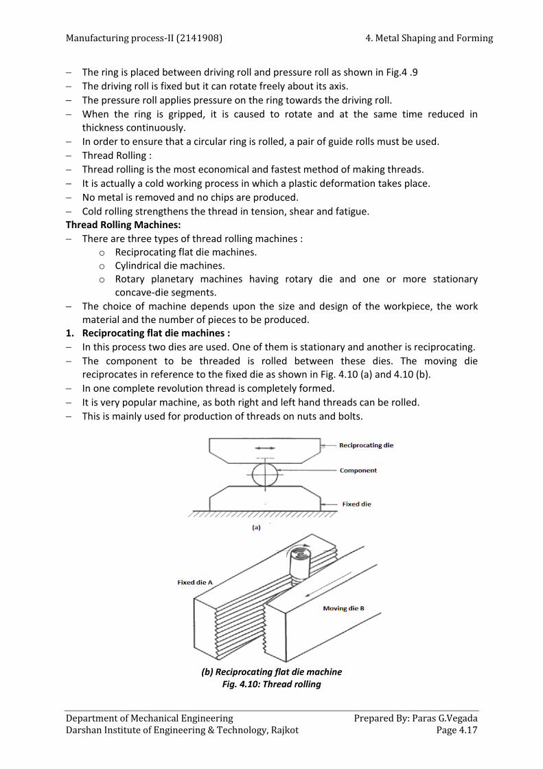
Manufacturing process-II (2141908) 4. Metal Shaping and Forming
Department of Mechanical Engineering Prepared By: Paras G.Vegada Darshan Institute of Engineering & Technology, Rajkot Page 4.17
− The ring is placed between driving roll and pressure roll as shown in Fig.4 .9 − The driving roll is fixed but it can rotate freely about its axis. − The pressure roll applies pressure on the ring towards the driving roll. − When the ring is gripped, it is caused to rotate and at the same time reduced in
thickness continuously. − In order to ensure that a circular ring is rolled, a pair of guide rolls must be used. − Thread Rolling : − Thread rolling is the most economical and fastest method of making threads. − It is actually a cold working process in which a plastic deformation takes place. − No metal is removed and no chips are produced. − Cold rolling strengthens the thread in tension, shear and fatigue. Thread Rolling Machines: − There are three types of thread rolling machines :
o Reciprocating flat die machines. o Cylindrical die machines. o Rotary planetary machines having rotary die and one or more stationary
concave-die segments. − The choice of machine depends upon the size and design of the workpiece, the work
material and the number of pieces to be produced. 1. Reciprocating flat die machines : − In this process two dies are used. One of them is stationary and another is reciprocating. − The component to be threaded is rolled between these dies. The moving die
reciprocates in reference to the fixed die as shown in Fig. 4.10 (a) and 4.10 (b). − In one complete revolution thread is completely formed. − It is very popular machine, as both right and left hand threads can be rolled. − This is mainly used for production of threads on nuts and bolts.
(b) Reciprocating flat die machine
Fig. 4.10: Thread rolling

4. Metal Shaping and Forming Manufacturing process-II (2141908)
Prepared By: Paras G. Vegada Department of Mechanical Engineering Page 4.18 Darshan Institute of Engineering & Technology, Rajkot
Advantages of Thread Rolling: − It is the fastest method of producing a thread, with production rate more than − 2000 pieces per minute. − Being a chip less forming process, there is lot of material saving (about 16 to 27 %). − During thread rolling, the material is strained plastically and work hardened, therefore it
becomes stronger against tension and fatigue. − A rolled thread is superior to one that has been cut since the process work hardens − the thread surface and promotes a grain direction which adds to the strength of the
thread. − Surface finish is better than thread milling and it is in the order of 0.08 to 0.2 pm. Limitations of Thread Rolling: − Best suitable only for diameters upto 20 mm. − Necessary to hold close blank tolerance. − Uneconomical for low quantities. − Cannot roll material having a hardness exceeding RC 37. − Only external threads can be rolled. Thread Rolling Applications: − To produce external threads, thread rolling is the best method. − Electric light bulb, wood screws, machine screws, sheet metal screws, hooks and eyes of
bolts are produced by this method. − Thread rolling is also used for producing threads on stamped parts. 4.11 Forging − Forging is the process of shaping heated metal by the application of sudden
blows(hammer forging) or steady pressure (press forging) and makes use of the characteristic of plasticity of the material.
− Forging is metal forming process which may be done by hand or by machine. − In case of hand forging, hammering is done by hand; whereas forging by machine
involves the use of dies and it is mostly used in mass production. Refer Fig. 4.11.
Fig. 4.11: Forging process

Manufacturing process-II (2141908) 4. Metal Shaping and Forming
Department of Mechanical Engineering Prepared By: Paras G.Vegada Darshan Institute of Engineering & Technology, Rajkot Page 4.19
− Whatever may be the method of applying pressure for shaping the metal, the primary requirement is to heat the metal to a definite temperature to bring it into the plastic state.
− This may done in an open hearth, called as Smith's forge for small jobs or in closed furnaces for large jobs.
− The shop in which the work is carried out is called as Smithy or Smith's shop. − The metals which are used in forging process must possess the required ductility. − We know that ductility refers to the capacity of a material to undergo deformation,
under tension without failure. − The commonly used forging materials are : Aluminium alloys, copper alloys, low carbon
steels, alloy steels, nickel alloys, tungsten alloys, magnesium alloys, titanium alloys, beryllium, etc.
4.11.1 Advantages, Disadvantages and Applications of Forging Process Advantages − In forging process, grain flow is continuous and uninterrupted. It gives greater strength
and toughness to the forged components. Fig. 4.12 shows three spanners, produced through three different methods casting, machining and forging. The cast spanner is the weakest of all, the machined spanner is relatively stronger and the strongest will be the forged spanner Forged components requires minimum surface finish.
− The forging process gives the high dimensional accuracy. − Forged components have better mechanical properties like strength, toughness, etc. − Forged components have better resistance to shock and vibrations. − Welding of forged parts is easy.
Fig. 4.12 : Spanners produced through three different methods
Disadvantages − Complicated shapes cannot be forged easily. − Forging process is mostly suitable for large parts. − Forging of brittle materials is difficult. − Due to high cost of forging dies, forging process is costly. − More noise and vibrations are produced during the process. Applications − Forging process is used in the manufacturing of following components : − Car axles, crankshafts, connecting rods, leaf springs, crane hooks, jet engine turbine dies
and blades. − Levers, flanges, propellers, hollow bodies, railway wheel disks, tank bottoms.

4. Metal Shaping and Forming Manufacturing process-II (2141908)
Prepared By: Paras G. Vegada Department of Mechanical Engineering Page 4.20 Darshan Institute of Engineering & Technology, Rajkot
− Air-craft and rocket parts, knife blades, bolts, nuts, washers, collars, gear blanks, etc. 4.12 Types of Forging process − Forging process is classified as follows : 1. According to the working temperature
a. Hot forging − Most of the forging operations are performed above the recrystallization temperature
but below the melting point of the metals. − During the process there is deformation of the metal which reduces the strength and
increases the ductility of metal. b. Cold forging
− For certain products like bolts, rivets, screws, pins, nails, etc. cold forging is also very common.
− It increases the strength which results from the strain hardening of the component. 2. According to the method of applying the blows
a. Impact forging − In this method of forging, a machine that applies impact load on the workpiece is called
as forging hammer. b. Gradual pressure forging
− In this method of forging, a machine that applies gradual pressure on the workpiece called as forging press.
3. According to the degree to which the flow of workpiece is constrained by the dies a. Open-die forging
− In this method of forging, the workpiece is compressed between two flat dies which allows the metal to flow without constraint in a lateral direction relative to the die surfaces. Refer Fig.4.13 (a). b. Closed-die or impression-die forging
− In this method, the die surfaces contain an impression or shape which is applied to the workpiece during the compression. Refer Fig. 4.13 (b).
Fig. 4.13 : Types of forging operations

Manufacturing process-II (2141908) 4. Metal Shaping and Forming
Department of Mechanical Engineering Prepared By: Paras G.Vegada Darshan Institute of Engineering & Technology, Rajkot Page 4.21
− During the operation, some portion of the workpiece flows beyond the die impression to form a flash. (Flash is excess metal which is trimmed off at the end). c. Flash less forging
− In this method, the workpiece is completely constrained within the die and no flash is produced. Refer Fig. 4.13 (c).
− The volume of the initial workpiece must be controlled closely so that it matches with the volume of the die cavity.
4.13 Open Die Forging − It is the simplest and important forging process. − The shapes generated by this process are simple like shafts, disks, rings, etc. − An example of open-die forging in the steel industry is the shaping of a large square cast
ingot into a round cross-section. − Open-die forging operations produce rough forms of workpiece hence, subsequent
operations are required to refine the parts to final shape. − Open-die forging process can be depicted by a solid workpiece placed between the two
flat dies (lower die is fixed and upper die is moving) and reduced in height by compressing it. This process is called as upsetting or flat-die forging. Refer Fig. 4.14.
Fig. 4.14: Open-die forging
− The deformation of the workpiece is shown in Fig. 4.26. Due to constancy of volume, any reduction in height of the workpiece increases its diameter.
− In Fig. 4.14 (b) the workpiece is deformed uniformly but practically the workpiece develops a barrel shape which is called as pancaking or barreling.
− It is caused by the frictional forces at the die-workpiece interfaces and it can minimised by using an effective lubricant.
− Some of the important operations performed in open-die forging process are as follows : 1. Fullering − It is performed to reduce the cross-section and redistribute the metal in a workpiece in
preparation for subsequent shape forging. − It is performed with dies of convex surfaces. Refer Fig. 4.15 (a). 2. Edging − Its working principle is similar to fullering operation, only the difference is that the dies
have concave surfaces. Refer Fig. 4.15 (b).

4. Metal Shaping and Forming Manufacturing process-II (2141908)
Prepared By: Paras G. Vegada Department of Mechanical Engineering Page 4.22 Darshan Institute of Engineering & Technology, Rajkot
3. Cogging − It consists of a sequence of forging compressions along the length of workpiece to
reduce the cross-section and to increase the length. Refer Fig. 4.15 (c). − It is used to produce blooms, slabs, etc. from the cast ingots. − The dies used in this operation are flat or have slightly contoured surfaces. − This operation is also called as incremental forging.
Fig. 4.15: Open-die forging operations
4.14 Impression Die or Closed Die Forging − Impression-die or closed-die forging is performed with dies which contain the inverse of
the required shape of the component. Refer Fig. 4.16.
Fig. 4.16: Closed or impression dies forging
− Initially the cast ingot is placed between the two impressed dies. As the die closes to its final position, flash is formed by the metal.
− This flash flows beyond the die cavity and into the small gap between the die plates.
Manufacturing process-II (2141908) 4. Metal Shaping and Forming
Department of Mechanical Engineering Prepared By: Paras G.Vegada Darshan Institute of Engineering & Technology, Rajkot Page 4.23
− The formed flash must be cut away from the final component in a subsequent trimming operation but it performs an important function that, it increases the resistance to the deformation of the metal.
− The initial steps in the process are used to redistribute the metal in the work part to achieve a uniform deformation and required metallurgical structure in the subsequent steps.
− The final steps bring the component to its final geometry. Also, when drop forging is used, number of blows of the hammer may be used for each step.
− As flash is formed during the process, this process is used to produce more complex components by using dies.
4.14.1 Comparison between Open-die and Closed-die Forging Sr. No. Open-die forging Closed-die forging
1. In this method, the workpiece is compressed between the two flat dies.
In this method, the workpiece is compressed between the two impressed dies.
2. The cost of dies is low. The cost of dies is high. 3. The process is simple. The process is complex. 4. During the process there is poor
utilization of the material During the process there is better utilization of the material.
5. After the process, machining of components is required.
After the process, machining of components is not required.
6. The dimensional accuracy of obtained products is not good.
The dimensional accuracy of obtained products is good.
7. This process is used for low quantity production.
This process is used for high quantity production.
8. It is suitable only for production of simple components.
It is suitable for production of simple and complex components.
4.15 Hammers and other Forging Tools − Hammers are classified into different groups as shown in Fig. 4.17 − The hammers are used by a Smith in order to give the desired shape to the heated metal
piece.
Fig. 4.17 : Types of hammers
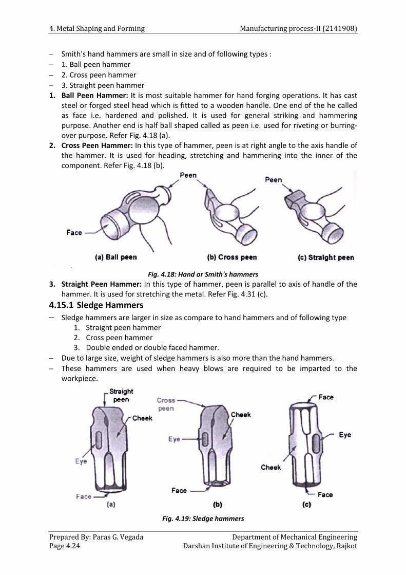
4. Metal Shaping and Forming Manufacturing process-II (2141908)
Prepared By: Paras G. Vegada Department of Mechanical Engineering Page 4.24 Darshan Institute of Engineering & Technology, Rajkot
− Smith's hand hammers are small in size and of following types : − 1. Ball peen hammer − 2. Cross peen hammer − 3. Straight peen hammer 1. Ball Peen Hammer: It is most suitable hammer for hand forging operations. It has cast
steel or forged steel head which is fitted to a wooden handle. One end of the he called as face i.e. hardened and polished. It is used for general striking and hammering purpose. Another end is half ball shaped called as peen i.e. used for riveting or burring-over purpose. Refer Fig. 4.18 (a).
2. Cross Peen Hammer: In this type of hammer, peen is at right angle to the axis handle of the hammer. It is used for heading, stretching and hammering into the inner of the component. Refer Fig. 4.18 (b).
Fig. 4.18: Hand or Smith's hammers
3. Straight Peen Hammer: In this type of hammer, peen is parallel to axis of handle of the hammer. It is used for stretching the metal. Refer Fig. 4.31 (c).
4.15.1 Sledge Hammers − Sledge hammers are larger in size as compare to hand hammers and of following type
1. Straight peen hammer 2. Cross peen hammer 3. Double ended or double faced hammer.
− Due to large size, weight of sledge hammers is also more than the hand hammers. − These hammers are used when heavy blows are required to be imparted to the
workpiece.
Fig. 4.19: Sledge hammers

Manufacturing process-II (2141908) 4. Metal Shaping and Forming
Department of Mechanical Engineering Prepared By: Paras G.Vegada Darshan Institute of Engineering & Technology, Rajkot Page 4.25
− To avoid the damage of workpiece surface, the striking surface of the sledge hammer is made slightly convex and smooth.
− The construction of straight peen and cross peen hammers is similar as discussed in hand hammers. Refer Fig. 4.19 (a) and (b).
− If the hammer has no peen formation and instead carries flat faces at both ends, then it is called as double ended or double faced hammer. Refer Fig. 4.19 (c).
4.15.2 Power Hammers − During forging, heavy components require a great degree of deformation which is not
possible by using hand hammers. − When forging with power machines, the deformation of the heated metal takes place
either under the action repeated blows or the action of gradually applied pressure. − Machines which work on the principle of repeated blows are called as forging hammers
or power hammers, whereas those apply gradual pressures are called as forging presses. − Forging or power hammers are of following types :
1. Spring hammer 2. Pneumatic hammer 3. Steam or air hammer 4. Drop hammer
1. Spring Hammer : − It has a simple design to regulate the speed and force of its blows. − It is very light type of power hammer and suitable for small forgings. − It consists of a heavy rigid frame carrying a vertical projection at its top which act as a
housing for bearing in which leaf or laminated spring oscillates. − One end of this spring is connected to the connecting rod and other end is connected to
a vertical tup which reciprocates between fixed guides. Refer Fig. 4.20.
Fig. 4.20: Spring hammer
− The connecting rod is attached to on eccentric sheave, which is further connected to the crank wheel.

4. Metal Shaping and Forming Manufacturing process-II (2141908)
Prepared By: Paras G. Vegada Department of Mechanical Engineering Page 4.26 Darshan Institute of Engineering & Technology, Rajkot
− To operate the hammer, treadle is pressed downwards that makes the sheave to rotate through the crank wheel and hence, leaf spring starts oscillating in the bearing.
− This oscillation of spring causes the reciprocating motion of the tip and thus, required blows are provided on the workpiece.
− To adjust the stroke of the connecting rod and intensity of blows, hand lever is used. 2. Pneumatic Hammer : − Design of pneumatic hammer varies with the different manufacturers. − Fig. 4.21 shows a commonly used design of pneumatic hammers which consists of
compressor cylinder and ram cylinder.
Fig. 4.21 : Pneumatic hammer
− In these hammers, the compressor cylinder compresses the air and delivers it to the ram cylinder. By using this compressed air pressure, the ram cylinder piston is actuated.
− A hand lever operates an air valve provided on the air passage from compressor cylinder to ram cylinder.
− Piston of ram cylinder carries tup at its bottom which can slide inside the fixed guides. − The compression of the reciprocating cylinder is obtained with the help of crank drive
which is operated by a reduction gear drive. − Pneumatic hammer can produce 70 to 200 blows/minute. 3. Steam Hammer : − Steam or air hammers are similar in design to the pneumatic hammers. − Steam or air hammers are normally consists of double acting cylinder i.e. steam or air is
admitted on both sides of the piston. − Hence, both the strokes are initiated and performed by the pushing action of
compressed air or steam. − In this type of hammer, compression of air or steam takes place separately and not
within the hammer.

Manufacturing process-II (2141908) 4. Metal Shaping and Forming
Department of Mechanical Engineering Prepared By: Paras G.Vegada Darshan Institute of Engineering & Technology, Rajkot Page 4.27
− Fig. 4.22 (a) arid (b) shows the working principle of single acting and double acting steam or air hammers.
Fig. 4.22: Steam or air hammers
− In single acting type, the air or steam is admitted into the cylinder through a part near its bottom which pushes the piston upwards.
− The steam supply is then cut off when the piston attains the required height and the outfalls under the gravity on the anvil.
− Before the end of upward stroke, air from atmosphere is admitted into the cylinder through the air ports, which provides cushioning action and lowers the speed of upward moving piston.
− In case of double acting type, steam or air is admitted under pressure on both sides of the piston and both the strokes are operated by the fluid.
4.16 Drop forging − Drop forging is different from smith's forging as in drop forging closed impressions
rather than open face of flat dies are used − This process utilizes closed impression die to obtain the required shape of the
component. − The dies are matched and separately attached to the movable ram and the fixed anvil. − The forging is produced by impact or pressure, which compels hot and pliable metal to
confirm to the shape of the dies.

4. Metal Shaping and Forming Manufacturing process-II (2141908)
Prepared By: Paras G. Vegada Department of Mechanical Engineering Page 4.28 Darshan Institute of Engineering & Technology, Rajkot
− During the operation, there is a drastic flow of metal in the dies caused by repeated blows of hammers on the metal.
− To ensure proper flow of the metal during the intermittent blows, the operation is divided into a number of steps.
− Each step changes the metal form gradually, controlling the flow of the metal until the final shape is obtained.
− The number of blows required varies according to the size and shape of the part, forging quality and required tolerances.
− The equipment used for applying the blows is called as drop hammer. − Three types of drop hammers are used in making drop forgings :
o Board or gravity hammer o Air-lift hammer o Power drop hammer or steam hammer
− Fig. 4.23 shows the principle of a board or gravity hammer.
Fig. 4.23 : Principle of a board or gravity hammer
− The drop forging die consists of two halves i.e. lower half and upper half. − The lower half of the die is fixed to the anvil of the machine while upper half is fixed to
the ram. − The heated stock or the workpiece is kept in the lower die while the ram delivers four to
five blows on the metal in quick succession, so that the metal spreads and fills the die cavity.
− The force of the blow can be varied by changing the distance of the fall. − The anvil which must absorb the blow is generally 20 times heavier than the hammer. − A board hammer which works rapidly, gives over 300 blows per minute. − Board hammer can do a wide variety of work and they are less expensive as compare to
the others. − Components manufactured by drop forging are car axles, crankshafts, connecting rods,
leaf springs, crane hooks, jet engine turbine dies and blades. Disadvantages of Drop Forging: − The boards are liable to frequent breakage.

Manufacturing process-II (2141908) 4. Metal Shaping and Forming
Department of Mechanical Engineering Prepared By: Paras G.Vegada Darshan Institute of Engineering & Technology, Rajkot Page 4.29
− The intensity of blow cannot be controlled during the stroke. − Dimensional accuracy is less. − The life of the hammers and dies is less. − More noise and vibrations are produced during the operation. 4.16.1 Press Forging − It is done in presses rather than by using hammers. − The action is relatively slow squeezing instead of delivering heavy blows and penetrates
deeply because it gives the metal time to flow. − Press forgings are shaped at each impression with a single smooth stroke and they stick
to the die impression more rigidly. − Press forgings are generally more accurate dimensionally than drop forgings. − Press for forgings may be of two types i.e. hydraulic and mechanical press. − The dies used carry relatively less draft and hence more complicated shapes can be
forged. − The life of the presses and dies is longer than that of the hammer and dies used on
them. − The process does not require highly skilled operator because the speed, pressure and
travel of the die are automatically controlled. − There are less vibrations and noise as compared to hammering. − Presses of 500 to 600 tonnes capacities are generally used. − Press forging is used for the manufacturing of large levers, flanges, toothed wheels,
crankshafts, propellers, hollow bodies, railway wheel disks, tank bottoms, panels and other bodies of air-craft and rocket bodies.
4.16.2 Machine or Upset Forging − Machine forging is also called as hot heading. − It consists of applying pressure longitudinally on a hot bar, which is gripped firmly
between grooved dies, to upset a required portion of its length. − All forgeable metals can be upset through this process. − They may have any shape of cross-section, but round shape is most commonly used. − The equipment used for this type of forging is known as forging machine or up setter. − The machine provides forging pressure in a horizontal direction. − The dies are so designed that, the complete operation is performed in several stages and
the final shape is attained gradually. − The operation is performed by using die and punch which is called as heading tool, as
shown in Fig. 4.24.
Fig. 4.24 : Upset forging
− The die is either made hollow to receive the round bar through it or in two parts to open out and receive the bar.

4. Metal Shaping and Forming Manufacturing process-II (2141908)
Prepared By: Paras G. Vegada Department of Mechanical Engineering Page 4.30 Darshan Institute of Engineering & Technology, Rajkot
− Between the heading tool and the die, a mechanical stop is placed which determine the correct projecting length of the bar.
− After the bar has been gripped firmly, with its correct length projecting outside, the stop is replaced and the heading tool is advanced into the die.
− Many such strokes are required to complete the upsetting. − Forging of the ring and rod types with all kinds of heads and shoulders such as be bolts,
nuts, washers, collars, pinion gear blanks, etc. can be easily produced by this process. Advantages of Machine Forging: − The quality of machine forging is better than the other forging methods. − The dies carry no draft; hence flash is not produced on the parts. − Better dimensional accuracy can be obtained. − With the help of this forging process piercing can also be done with considerable
accuracy. − Forging machines have higher productivity and their maintenance is less expensive than
the other methods. − The process can be automated. Disadvantages of Machine Forging: − Due to material handling difficulties, heavier components cannot be forged easily. − The components having diameter more than 250 mm cannot be forged by this process. − Intricate and unsymmetrical components are difficult to be forged. − Tooling cost is high. 4.16.3 Roll Forging − Roll forging process consists of placing raw stock between two roll dies which are of
semi-cylindrical form and are grooved to impart a desired shape to the workpiece being forged.
− Thee roll dies are carried on roll shafts and rotate continuously towards the operator. Refer Fig. 4.25 (a) and (b).
Fig. 4.25: Principle of operation of a roll forging machine
− Fig. 4.49 (a) shows the rolls in an open condition, with the heated workpiece in the tong and resting on the guide.
− In Fig. 4.49 (b) the rolls are brought together, with the stock gripped in the grooves of the rolls.

Manufacturing process-II (2141908) 4. Metal Shaping and Forming
Department of Mechanical Engineering Prepared By: Paras G.Vegada Darshan Institute of Engineering & Technology, Rajkot Page 4.31
− The rolling action forces the stock towards the operator. − When the dies are again in an open condition the stock is placed in appropriate grooves
of the rolls and the operations are repeated until the required shape is not obtained. − This process is also used to make large reductions in the cross-section and distribution of
the metal of a billet, hence saving considerable work in the forging hammer or press. − By using roll forging, parts such as knife blades, automobile drive shafts, axles, leaf
springs and gear-shift levers are made. 4.17 Forging Operations − A number of operations are used to change the shape of the raw material to the finished
form. A typical smith forging operations are as follows : 1. Upsetting 2. Drawing out or drawing down 3. Cutting 4. Bending 5. Punching and Drifting 6. Setting down 7. Welding
1. Upsetting : − Upsetting is also called as jumping or heading. − It is a process through which the cross-section of a metal piece is increased with a
corresponding increase in its length. − When a metal is sufficiently heated, it acquires the plastic stage, so that it becomes soft. − If some pressure (blows) is applied to it, then the metal tends to swell or increase in its
dimensions at right angles to the direction of application of force with corresponding reduction in its dimensions.
Fig. 4.26: Upsetting a bar Fig. 4.27: Drawing out
− This is what actually takes place during upsetting or jumping a metal part. Refer Fig 4.50 2. Drawing out or drawing down : − Drawing out is exactly a reverse process to that of upsetting. − It is employed when a reduction in thickness, width of a bar is desired with a
corresponding increase in its length.

4. Metal Shaping and Forming Manufacturing process-II (2141908)
Prepared By: Paras G. Vegada Department of Mechanical Engineering Page 4.32 Darshan Institute of Engineering & Technology, Rajkot
− The desired effect is obtained by the use of either the peen of a cross peen hammer, a set of fullers or a pair of swages.
− Fig. 4.51 shows the drawing out operation by using top and bottom fullers. 3. Cutting : − Cutting-off is a form of a chiseling whereby a long piece of stock is cut into several
specified lengths, or a forging is cut-off from its stock. − A notch is first made about one half the thickness or diameter of the stock. − After that, the workpiece must be turned through an angle of 180° and the chisel is
placed exactly opposite the notch. − The required length of metal can then be cut-off by giving the chisel a few blows with a
sledge hammer. 4. Bending : − Bending is an important operation in smith forging and it is very frequently used. − It may be classified as angular or curvilinear. − Any required angle or curvature can be made through this operation. − Bending operation is carried out on the edge of the anvil or on the perfectly square edge
of a rectangular block. − For making a right angle bend, particular portion of the stock is heated and jumped on
the outer surface. − When metal is bent, the layers of metal on the inside are compressed and those on the
outside are stretched. 5. Punching and Drifting : − The term punching refers to the operation in which a punch is forced though a
workpiece to produce a hole. − The workpiece is first heated and then placed on the anvil face. − The punch is then forced into it upto about half its thickness. − The workpiece is then turned upside down and placed over a tool called as bolster. − The punch is again forced into the workpiece and made to pass through by hammering. − Punching without using a die, is generally followed by drifting. − In drifting, a tool known as drift, is made to pass through the punched hole to produce a
finished hole of the required size. 6. Setting down : − Setting down is the operation through which the rounding of a corner is removed, to
make it square by using a set hammer. − By putting the face of the hammer over the round portion, formed by bending or
fullering of the corner and hammering it at the top a local reduction in thickness takes place resulting in sharp corner.
− Hence, finishing operation is performed through which the unevenness of a flat surface is removed by using a flatter or a set hammer.
7. Welding : − Welding or shutting is the principle operation performed by the smith. − The metal which remains pasty over a wide range of temperature is most easily welded. − For production of sound weld, the surfaces in contact must be perfectly clean, both
mechanically and chemically, so that cohesion will take place when the metal is in aplastic state.

Manufacturing process-II (2141908) 4. Metal Shaping and Forming
Department of Mechanical Engineering Prepared By: Paras G.Vegada Darshan Institute of Engineering & Technology, Rajkot Page 4.33
− A protection to the metal is a coating of flux which covers the surfaces of the metal and prevents oxidation.
− A forge weld is made by hammering together the ends of two bars which have been formed to the corrected shape and heated to a welding temperature in a forge fire.
− The method of preparing the metal pieces for welding is called as scarfing. 4.18 Extrusion − Extrusion is a compression process in which the work metal is forced to flow through a
small opening which is called as die to produce a required cross-sectional shape. − The extrusion process is similar to squeezing toothpaste or cream from a tube. − Almost any solid or hollow cross-section may be produced by extrusion process. − As the geometry of the die remains same during the operation, extruded parts have the
same cross-section. − During the process, a heated cylindrical billet is placed in the container and it is forced
out through a steel die with the help of a ram or plunger. − The products made by extrusion process are tubes, rods, railings for sliding doors,
structural and architectural shapes, door and window frames, etc. − Extrusion process is suitable for the non-ferrous alloys, steel alloys, non-ferrous metals,
stainless steel, etc. − Extrusion process is carried out on horizontal hydraulic press machines which are rated
from 250 to 5500 tonnes in capacity. − Extrusion process is classified as follows : 1. According to physical configuration
a. Direct (Forward) extrusion b. Indirect (Backward) extrusion
2. According to working temperature a. Hot extrusion b. Cold extrusion
4.18.1 Direct Extrusion − Direct or forward hot extrusion is most widely used and the maximum numbers of
extruded parts are produced by this method. − Fig. 4.28 shows the direct extrusion process in which the raw material is a billet. − A billet is heated to its forging temperature and fed into the machine chamber. − Pressure is applied to the billet with the help of ram or plunger which forces the material
through the die. − The length of extruded part will depend on the billet size and cross-section of the die. − The extruded part is then cut to the required length. − As the ram approaches the die, a small portion of billet remains which cannot be forced
through the die opening. This extra portion is known as butt which is separated from the product at the end.
− When the billet is forced to flow through the die opening, there is friction between the workpiece and chamber walls. This friction is overcome by providing additional ram force. This is the major problem with this process.
− To overcome this problem oxide layer is provided on the billet or dummy block is used between the ram and billet.
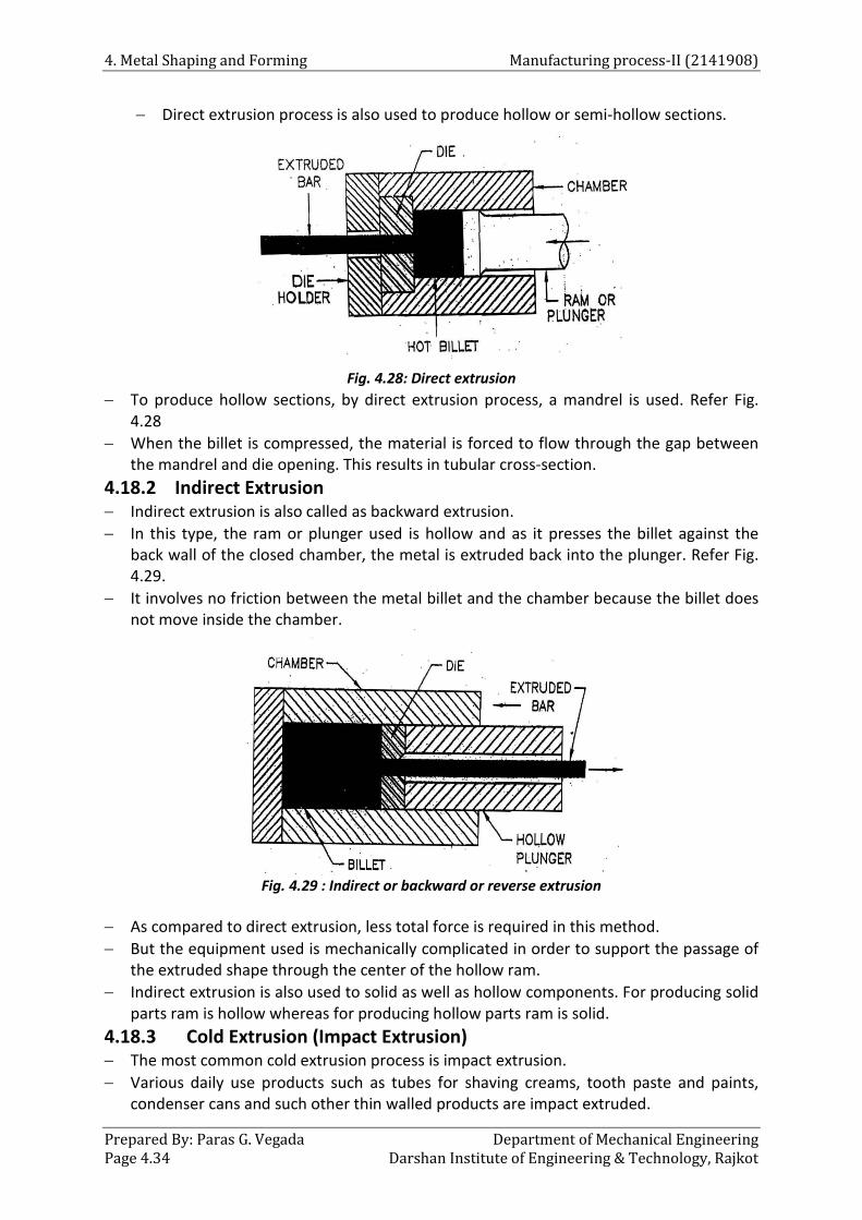
4. Metal Shaping and Forming Manufacturing process-II (2141908)
Prepared By: Paras G. Vegada Department of Mechanical Engineering Page 4.34 Darshan Institute of Engineering & Technology, Rajkot
− Direct extrusion process is also used to produce hollow or semi-hollow sections.
Fig. 4.28: Direct extrusion
− To produce hollow sections, by direct extrusion process, a mandrel is used. Refer Fig. 4.28
− When the billet is compressed, the material is forced to flow through the gap between the mandrel and die opening. This results in tubular cross-section.
4.18.2 Indirect Extrusion − Indirect extrusion is also called as backward extrusion. − In this type, the ram or plunger used is hollow and as it presses the billet against the
back wall of the closed chamber, the metal is extruded back into the plunger. Refer Fig. 4.29.
− It involves no friction between the metal billet and the chamber because the billet does not move inside the chamber.
Fig. 4.29 : Indirect or backward or reverse extrusion
− As compared to direct extrusion, less total force is required in this method. − But the equipment used is mechanically complicated in order to support the passage of
the extruded shape through the center of the hollow ram. − Indirect extrusion is also used to solid as well as hollow components. For producing solid
parts ram is hollow whereas for producing hollow parts ram is solid. 4.18.3 Cold Extrusion (Impact Extrusion) − The most common cold extrusion process is impact extrusion. − Various daily use products such as tubes for shaving creams, tooth paste and paints,
condenser cans and such other thin walled products are impact extruded.

Manufacturing process-II (2141908) 4. Metal Shaping and Forming
Department of Mechanical Engineering Prepared By: Paras G.Vegada Darshan Institute of Engineering & Technology, Rajkot Page 4.35
− The raw material is in slug form which have been turned from a bar or punched from a strip.
− By using punch and dies, the operation is performed. − The slug is placed in the die and struck from top by the punch operating at high pressure
and speed. Refer Fig. 4.30.
Fig. 4.30: Principle of impact extrusion
− The metal flows up along the surface of the punch, forming a cup shaped component. − When the punch moves up, to separate the component from the punch compressed air
is used. − At the same time, a fresh slug is fed into the die. − The rate of production is fairly high i.e. 60 components per minute. − This process is used only for soft and ductile materials such as lead, tin, aluminum, zinc
and some of their alloys. − The main advantages of this process are its speed, product uniformity and no wastage. 4.18.4 Hydrostatic Extrusion − In this type of extrusion process, the billet is surrounded by a working fluid which is
pressurised by the ram to apply the extrusion force. − In this process, hydraulic fluid remains between the billet and the chamber walls hence
eliminating the contact between them. Also, it avoids the friction between the metal billet and the walls of the chamber.
− Fig. 4.31 shows the working principle of hydrostatic extrusion. − Due to absence of wall friction, extrusion of very long billets or even wires and large
reductions can be taken.
Fig. 4.31: Hydrostatic extrusion
− During the process, the ram does not directly act on the billet, instead of that, it acts on the hydraulic fluid which forces the billet through the die and produces the extrusions.

4. Metal Shaping and Forming Manufacturing process-II (2141908)
Prepared By: Paras G. Vegada Department of Mechanical Engineering Page 4.36 Darshan Institute of Engineering & Technology, Rajkot
− The materials which cannot be extruded successfully by conventional methods can be extruded by this process.
4.19 Defects in Extrusion − Following are the three basic categories of extrusion defects :
i. Center cracking ii. Surface cracking iii. Piping defect i. Center cracking − It is commonly called as internal breakage, cheveron cracking, arrowhead fracture and
center burst. − As the workpiece is being extruded from the die, stresses in the work break the material. − It causes cracks to form along the central axis of extruded part. Refer Fig. 4.59. − This defect occurs due to difference in metal flow of central region and outer region. − Surface cracking − In surface cracking, excessive stresses on the surface of the extruded part cause the
breakage on the surface. Refer Fig. 4.60. − These cracks usually occur along the grain boundaries. − Surface cracking occurs due to high extrusion temperature, friction and speed. − Piping defect − Piping defect is commonly called as tail pipe or fish tailing defect and occurs during
direct extrusion at the end opposite to the die. − Piping defects results due to improper metal flow during the extrusion operation. − A funnel shaped void of material at the end of the work is seen in this defect. 4.20 Wire Drawing − Drawing is an operation in which the cross-section of a bar, rod or wire is reduced by
pulling it through a die opening. − The general features of the drawing process are similar to extrusion. But the difference
is that, in drawing the workpiece is pulled through the die whereas in extrusion workpiece is pushed through the die.
− During the process, tensile as well as compressive stresses are produced in the material. − The main difference between the bar drawing and wire drawing is the stock
size(workpiece size). Bar drawing is used for large diameter (bar and rod) stock whereas wire drawing is used for small diameter stock.
Fig. 4.32(a) : Wire drawing
− Wire sizes upto 0.03 mm can be drawn by wire drawing process. − The process consists of pulling the hot drawn bar or rod through a die of which the bore
size is similar to the finished product size.

Manufacturing process-II (2141908) 4. Metal Shaping and Forming
Department of Mechanical Engineering Prepared By: Paras G.Vegada Darshan Institute of Engineering & Technology, Rajkot Page 4.37
− Depending upon the material to be drawn and the amount of reduction required, total drawing can be accomplished in a single die or in a series of successive dies.
− One end of the rod to be drawn into wire is made pointed, entered through the die and gripped at the other end by using tongs.
Fig. 4.32(b): Wire drawing
− After pulling a certain length, this end is wound to a reel or draw pulley. − When the pulley or reel is rotated, the rod is pulled through the die and its diameter
reduces. Refer Fig. 4.32 (a) & (b) − The die is made of highly wear resistant material. − Generally, tungsten carbide is used for die making. − The die made of tungsten carbide is suitably supported in a die holder which is made of
mild steel or brass. 4.21 Tube Drawing − As the initial tubing has been produced by other processes like extrusion, drawing can
be used to reduce the diameter or wall thickness of seamless tubes and pipes. − Tube drawing can be carried out either with mandrel or without mandrel − The simplest method of producing tubes and pipes is shown in Fig. 4.65 (a) in which
mandrel is not used. This method is also called as tube sinking. − In tube sinking method there is no control over the inner diameter and wall thickness of
tube.
Fig. 4.33: Tube drawing
− To overcome this drawback, mandrels are used in the process.

4. Metal Shaping and Forming Manufacturing process-II (2141908)
Prepared By: Paras G. Vegada Department of Mechanical Engineering Page 4.38 Darshan Institute of Engineering & Technology, Rajkot
− Fig. 4.33(b) shows tube drawing with mandrel. In this method, mandrel is fixed and attached to a long support bar to produce inside diameter and wall thickness during the process.

5 Sheet metal Forming
Course Contents
5.1 Introduction 5.2 Metals used in Sheet Metal
Working 5.3 Sheet Metal Operations 5.4 Die Classification 5.5 Spring Back 5.6 Riveting 5.7 Cold Heading
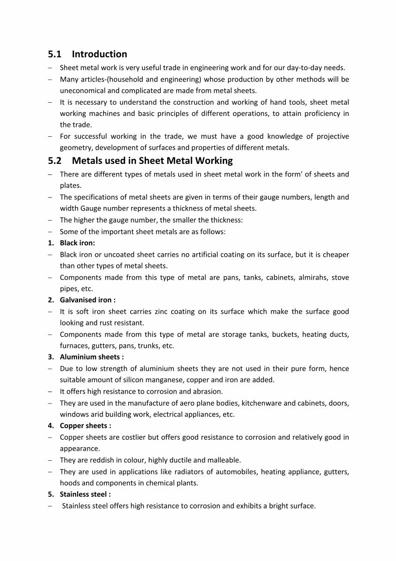
5.1 Introduction − Sheet metal work is very useful trade in engineering work and for our day-to-day needs. − Many articles-(household and engineering) whose production by other methods will be
uneconomical and complicated are made from metal sheets. − It is necessary to understand the construction and working of hand tools, sheet metal
working machines and basic principles of different operations, to attain proficiency in the trade.
− For successful working in the trade, we must have a good knowledge of projective geometry, development of surfaces and properties of different metals.
5.2 Metals used in Sheet Metal Working − There are different types of metals used in sheet metal work in the form' of sheets and
plates. − The specifications of metal sheets are given in terms of their gauge numbers, length and
width Gauge number represents a thickness of metal sheets. − The higher the gauge number, the smaller the thickness: − Some of the important sheet metals are as follows: 1. Black iron: − Black iron or uncoated sheet carries no artificial coating on its surface, but it is cheaper
than other types of metal sheets. − Components made from this type of metal are pans, tanks, cabinets, almirahs, stove
pipes, etc. 2. Galvanised iron : − It is soft iron sheet carries zinc coating on its surface which make the surface good
looking and rust resistant. − Components made from this type of metal are storage tanks, buckets, heating ducts,
furnaces, gutters, pans, trunks, etc. 3. Aluminium sheets : − Due to low strength of aluminium sheets they are not used in their pure form, hence
suitable amount of silicon manganese, copper and iron are added. − It offers high resistance to corrosion and abrasion. − They are used in the manufacture of aero plane bodies, kitchenware and cabinets, doors,
windows arid building work, electrical appliances, etc. 4. Copper sheets : − Copper sheets are costlier but offers good resistance to corrosion and relatively good in
appearance. − They are reddish in colour, highly ductile and malleable. − They are used in applications like radiators of automobiles, heating appliance, gutters,
hoods and components in chemical plants. 5. Stainless steel : − Stainless steel offers high resistance to corrosion and exhibits a bright surface.

− It is used in the manufacture of food containing equipments, dairy equipments, food processing plant, chemical plant, etc.
6. Tin plates : − Tin plates are used for those iron sheets which are coated with pure tin. − Tin plates are used for making food containers, containers for cooking oils and ghee,
cans, etc. 5.2.1 Hand Tools used in Sheet Metal Work − There are various types of hand tools used in sheet metal work. Some of them are as
follows: 1. Hammers: Hammers of different shapes and sizes are used in sheet metal work. To avoid
damage to the metal sheet, generally the face of hammers is made of soft materials. 2. Mallet: The purpose of wooden mallet is similar to hammer but used for light blows. 3. Swages: Swages are made to have curved surfaces. They are made in different sizes so as
to suit any required curvature. 4. Tongs: Tongs are generally flat types and used for holding metal sheets during the
Process. 5. Punches and shears: They are made in different shapes to suit the requirement like
hollow punch for cutting circular blanks, grooving punch for locking grooves, etc. 6. Stakes: Stakes are used to form the metal sheets into different shapes. They work as
supporting as well as forming tool. 7. Tri square and scribers : They are used to meet the marking requirements, similar to 8. Wing compass: It is used for drawing arcs and circles. 9. Pliers: Flat nose and round nose pliers are used for holding the workpiece and forming
various shapes. 10. In addition to all the above tools some other type of commonly used tools are as follows:
• Steel square • Bumping hammer • Mandrel
• Straight edge • Chisels • Files
5.3 Sheet Metal Operations − Press operations may be grouped into two categories i.e. cutting operations and forming
operations. In cutting operations, the sheet metal is stressed beyond its ultimate strength whereas; in forming operations the stresses are below the ultimate strength of the metal.
5.3.1 Metal Cutting Operations − In sheet metal cutting operations, the metal gets sheared hence these operations are
also called as shearing operations. − In these operations, the metal sheet is stressed beyond its ultimate strength. − Metal cutting operations include following operations :
1. Blanking 2. Punching (Piercing)
3. Notching 4. Perforating

5. Slitting 6. Lancing 7. Shaving
8. Shearing 9. Nibblin
1. Blanking − Blanking is the cutting operation of a flat metal sheet and the article punched out is
known as blank. − Blank is the required product of the operation and the metal left behind is considered as
a waste. Refer Fig. 5.1 and Fig. 5.4 (a).
Fig.5.1: Blanking.
2. Punching (Piercing) − It is the cutting operation with the help of which holes of various shapes are produced in
the sheet metal. − It is similar to blanking; only the main difference is that, the hole is the required product
and the material punched out to form a hole is considered as a waste. Refer Fig. 5.2 and Fig. 5.3 (b).
Fig. 5.2 : Punching (Piercing

(a) Blanking (b) Punching (Pireclng)
Fig. 5.3 : Blanking and punching (piercing) 3. Notching − It is similar to blanking operation, but in this full surface of punch does not cut the metal. − In this operation, metal pieces are cut from the edges of a sheet. Refer Fig. 5.4.
Fig. 5.4: Notching
4. Perforating − It is similar to piercing but the difference is that, to produce holes the punch is not of
round shape.
Fig. 5.4: Perforating

− In this process, multiple holes which are very small and close together are cut in the sheet metal. Refer Fig. 5. 4.
5. Slitting − It is the operation of making an unfinished cut through a limited length only. Refer Fig.
5.5.
Fig. 5.5: Slitting
6. Lancing − In this operation, there is a cutting of sheet metal through a small length and bending
this small cut portion downwards. Refer Fig. 5.7.
Fig. 5.7 : Lancing
7. Shaving − This operation is used for cutting unwanted excess material from the periphery of a
previously formed workpiece. Refer Fig. 5.8.
Fig. 5.8 : Shaving
− In this process very small amount of material is removed. 8. Shearing − It is a process of cutting a straight line across a strip; sheet or bar. Shearing process has
three important stages : i) Plastic deformation ii) Fracture (Crack propagation) iii) Shear
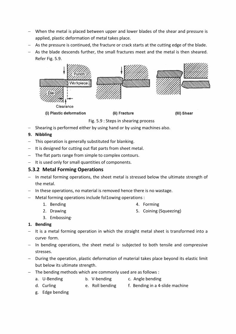
− When the metal is placed between upper and lower blades of the shear and pressure is applied, plastic deformation of metal takes place.
− As the pressure is continued, the fracture or crack starts at the cutting edge of the blade. − As the blade descends further, the small fractures meet and the metal is then sheared.
Refer Fig. 5.9.
Fig. 5.9 : Steps in shearing process
− Shearing is performed either by using hand or by using machines also. 9. Nibbling − This operation is generally substituted for blanking. − It is designed for cutting out flat parts from sheet metal. − The flat parts range from simple to complex contours. − It is used only for small quantities of components. 5.3.2 Metal Forming Operations − In metal forming operations, the sheet metal is stressed below the ultimate strength of
the metal. − In these operations, no material is removed hence there is no wastage. − Metal forming operations include fol1owing operations :
1. Bending 2. Drawing 3. Embossing·
4. Forming 5. Coining (Squeezing)
1. Bending − It is a metal forming operation in which the straight metal sheet is transformed into a
curve· form. − In bending operations, the sheet metal is· subjected to both tensile and compressive
stresses. − During the operation, plastic deformation of material takes place beyond its elastic limit
but below its ultimate strength. − The bending methods which are commonly used are as follows :
a. U-Bending b. V-bending c. Angle bending d. Curling e. Roll bending f. Bending in a 4-slide machine g. Edge bending
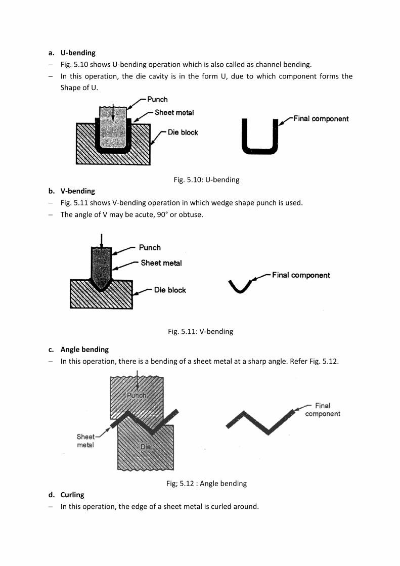
a. U-bending − Fig. 5.10 shows U-bending operation which is also called as channel bending. − In this operation, the die cavity is in the form U, due to which component forms the
Shape of U.
Fig. 5.10: U-bending
b. V-bending − Fig. 5.11 shows V-bending operation in which wedge shape punch is used. − The angle of V may be acute, 90° or obtuse.
Fig. 5.11: V-bending
c. Angle bending − In this operation, there is a bending of a sheet metal at a sharp angle. Refer Fig. 5.12.
Fig; 5.12 : Angle bending
d. Curling − In this operation, the edge of a sheet metal is curled around.

− The punch and die both are made to contain the cavity for cutting partially. − After the operation, punch moves up and workpiece is ejected out with the help of
plunger as shown in Fig: 5.13.
Fig. 5.13: Curling
− This process is used in the manufacturing of drums, pots, vessels, pans, etc. e. Roll bending − It is an operation in which generally large sheet metal parts are formed into curved
sections with the help of rolls. Refer Fig. 5.14.
Fig. 5.14: Roll bending
− When the sheet passes between the rolls, the rolls are brought towards each other to a configuration that achieves the required radius of curvature on the workpiece
− It is used for fabrication of large storage tanks, pressure vessels, etc. Also used to bend metal plates, tubes, structural shapes etc.
f. Bending in a 4-slide machine − This type of machine is used for bending of relatively short pieces . − These types of machines are available in different designs.

Fig. 5.15: Bending in a 4-slide machine
− The lateral movements of the dies are controlled with the vertical die movement to form the part of desired shapes. Refer Fig. 5.15.
g. Edge bending − It involves cantilever loading of sheet metal. − In this method a pressure pad is used to hold the base of the workpiece against the die
whereas the punch forces the workpiece to yield and bend over the edge of the die.
Fig. 5.16: Edge bending
− The edge bending operation is limited to bend 90° or less. − The dies used for edge bending is called as wiping dies. They can also be designed for
bend angles greater than 90°. − Due to pressure pad, wiping dies are more complicated and costly than the V-dies. − These dies are used for high production work. 2. Drawing − In this operation, punch forces a sheet metal blank to flow plastically into the clearance
between the punch and die.
Fig. 5.17: Drawing

− Finally, the blank takes a shape of cup. Refer Fig. 5.17. 3. Embossing − With the help of this operation, specific shapes or figures are produced on the sheet
metal. − It is used for decorative purposes or giving details like names, trade marks specifications,
etc. on the sheet metal. Refer Fig. 5.18.
Fig. 5.18: Embossing
4. Forming − In forming operation, sheet metal is stressed beyond its yield point so. that it takes a
permanent set and retains the new shape. − In this process, the shape of punch and die surface is directly reproduced without any
metal flow. Refer Fig. 5.19.
Fig. 5.19: Forming
− This operation is used in the manufacturing of door panels, steel furniture, air-craft bodies, etc.
5. Coining (Squeezing) − In coining operation, the metal having good plasticity and of proper size is placed within
the punch and die and a tremendous pressure is applied on the blank from both ends. Refer Fig. 5.20.

Fig. 5.20: Coining
− Under severe compressive loads, the metal flows in the cold state and fills up the cavity of the punch and die.
− This operation is used .in the manufacturing of coins, medals, ornamental parts, etc. 5.3.3 Deep Drawing − It is a process of making the cup-shaped parts from a flat sheet-metal blank. − To provide necessary plasticity for working, the blank is first heated an(then placed in
position over the die or cavity. Refer Fig. 5.21.
Fig. 5.21: Deep drawing
− The punch descends and pushes the metal through the die to form a cup; hence this process is also called as cupping.
− To obtain cup shaped pieces of the desired size and wall thickness, the process may be continued through a series of successively smaller dies and punches.
5.4 Die Classification a. Based on the types of press operations :
i. Shearing operations: Blanking, piercing, shearing, punching, perforating, notching, trimming, shaving, slitting, parting dies. All these are known as cutting dies.

ii. Bending operations: Angle bending, curling, forming, folding, plunging and reaming dies.
iii. Drawing operations: Flanging, embossing, bulging and cupping dies. iv. Squeezing operations: Flattering, swaging, coining, sizing, pressing dies.
b. Based on the type of die construction: • Simple die • Compound die • Combination die • Progressive die • Transfer die • Multiple die, etc.
5.4.1 Types of Dies 1. Simple dies : − Simple dies perform single operation for each stroke of the press slide. − The operation can be any of the operation listed under cutting or forming operations. 2. Compound dies : − In this type of dies, two or more operation can be performed at one station. − Only cutting operations are carried out hence these dies are considered as cutting dies.
Fig. 5.22: Compound die
− Fig. 5.22 shows a simple compound die in which a washer is made by one stroke of the press.
− The washer is produced by simultaneous blanking and piercing operation. − These dies are used because they are more accurate and economical in mass production
as compared to simple dies.

3. Combination dies : − In this also, more than one operation can be performed at one station. − It differs from compound die in such a way that, a cutting operation is combined with
bending or drawing operation. Refer Fig. 5.23.
Fig. 5.23: Combination die
− The die ring, which is mounted on the die shoe, is counter bored at the bottom to allow the flange of a pad to travel up and down.
− This pad is held with the face of the die by a spring. − A drawing punch of required shape is attached to the die shoe. − The blanking punch is secured to the punch holder. − A spring stripper strips the skeleton from the blanking punch. − A knockout extending through the centre opening and through the punch ·stem ejects
the port on the upstroke as it comes in contact with the knockout bar on the press. − In operation, the blank holding ring descents as the part is blanked, then the drawing
punch contacts and force the blank into the drawing die which is made in the blanking punch.
4. Progressive die: − A progressive die or follow on die has a series of stations. − At each station, an operation is performed on a workpiece during a press stroke. − Between the strokes, the piece in the metal strip is transferred to the next station. − A finished workpiece is made at each stroke of the press. − When the piercing punch cuts a hole in the strip, the blanking punch blanks out portion
of the metal in which a hole has been produced at a previous station.

− Hence, after each stroke a finished washer is produced. Refer Fig. 5.24.
Fig. 5.24: Progressive die
5. Transfer dies : − It is similar to progressive dies, where the stock is fed progressively from one station to
another. − In transfer dies, already cut blanks are fed mechanically from station to station. 6. Multiple dies : − These dies are also called as Gang dies. − It produces two or more work-pieces at each stroke of the press. − Number of simple dies and punches are ganged together, to produce more parts at each
stroke of the press.
5.5 Spring Back − In metal working processes, the total deformation of a workpiece will be the sum of
elastic deformation and plastic deformation. − We know that, elastic deformation is recoverable and plastic deformation is permanent. − Therefore, at the end of a metal working process, when the pressure on the metal is
released, there is an elastic recovery by the material. − Due to this elastic recovery, total deformation of metal will get reduced. − This phenomenon is called as spring back or elastic recovery. − It is important in cold working operations like forming, bending, etc.

− It depends upon the yield point strength of a metal. − The amount of spring back is difficult to predict hence cut and try methods are used. − To compensate for spring back, the cold deformation must be carried, beyond required
limit by an amount equal to the spring back. − Compensation for Spring Back − Following are some techniques to prevent the spring back:
i) Over bending ii) Bottoming iii) Stretch forming iv) Ironing
i. Over bending : − In this method, the workpiece is slightly over bent. − So, when it springs back it will achieve proper bend angle. − Over bending is done by setting the bending die and punch at smaller angle than
required. Refer Fig. 5.25.
Fig. 5.25: Spring back
ii. Bottoming : − In this method, the workpiece is subjected to high localized compressive stresses. − This results in the high compressive strains in metal that set most of the metals past the
yield point. − Hence, the spring back is avoided.
iii. Stretch forming : − Stretch forming strains the metal beyond elastic limit to give workpiece a permanent set. − This prevents the metal from spring back.
iv. Ironing : − Ironing can be accomplished by using wiping dies. − To iron the bend effectively, the distance between the punch and die should be kept less
than the material thickness.
5.6 Riveting − Riveting is a permanent fastening method. − Although, in modem manufacturing practices welding has replaced riveting to a
considerable extent still it has its own significance and use in several types of works.

− Riveting is largely used in the manufacture of boilers, pressure vessels, rail wagons and coaches, furnace bodies, bridges, etc.
− Rivets are permanent fastener and the plates joined together by riveting can be separated only either by chipping off the rivet heads or due to the failure of joint.
− Rivets are generally classified according to the shapes of their heads. − Some commonly used forms of heads are shown in Fig. 5.26. − The snap or cup head is the most commonly used form and gives a very strong joint. − Pan head provides the maximum strength and is widely used where strength is primary
consideration. − Conical head is generally formed by hand hammering and is mainly used in small work. − Countersunk head provides a flush head, as it does not project from the work surface
and is used in ship-building.
Fig. 5.26: Rivet heads
− Wrought iron and mild steel are the most commonly used materials for making rivets used in general engineering work although for ·very small work brass, copper and aluminium rivets are also used.
− These rivets are installed or fitted by following methods : i) Manually with hammer ii) Pneumatic hammer iii) Riveting machines iv) Handheld squeezers
− Rivets which are small enough and soft enough are fitted manually with hammer and bucking bar.
− Hard rivets are fixed by riveting machines and pneumatic hammers.

Advantages: − In case of riveting, there is no uneven heating and cooling of the workpiece and hence,
the problem of thermal distortions is avoided. − As the workpiece is not heated, during the process, additional (thermal) stresses are not
developed. − Less-skilled operator is required for the process. − Inspection of riveting work is easy than welding work. Disadvantages: − Riveted joints require additional cover a plates, straps, clip angles and large number of
rivets, which increases the weight of the structure. − Riveted joints are not tight and leak proof as that of the welded joints. − The cost of the riveted assembly is more than welded joint. − The riveting process takes more time than the welding.
5.7 Cold Heading − Cold forging is a cold upsetting process adapted for large scale production of small cold
upset parts from a wire stock. For example, small bolts, rivets, screws, pins, nails and small machine parts, small balls for ball bearings, etc.
− The machine used in the process is similar to hot forging. − The dies are used for forming the required shapes. − The rod is fed up to stops through straightening rolls, cut to size and pushed into the
header die.
Fig. 5.27 : Cold heading process

− The rod is gripped ~the die and a punch operates on the projected part to apply pressure and form the head.
− During the process, a compressive force or impact causes the metal to flow in some determined shape of the die.
− Fig. 5.27 shows the cold forming process in which the head will form in the punch, in the die, in punch and die or in between punch and die.


Department of Mechanical Engineering Prepared By: Disha V. Gondiya Darshan Institute of Engineering & Technology, Rajkot Page 6.1
6 PLASTIC, CERAMIC & GLASS PROCESSING
Course Contents
6.1 Polymer
6.2 Classification of Plastic
6.3 Ingredients of Moulding
Compound
6.4 Compression Moulding
6.5 Transfer Moulding
6.6 Injection Moulding
6.7 Extrusion Moulding
6.8 Blow Moulding
6.9 Calendaring
6.10 Thermoforming
6.11 Slush Moulding
6.12 Laminating
6.13 Ceramic
6.14 Shaping of Ceramic
6.15 Glass
6.16 Forming and Shaping of
Glass
6.17 Composite Materials
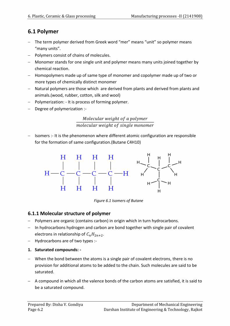
6. Plastic, Ceramic & Glass processing Manufacturing processes -II (2141908)
Prepared By: Disha V. Gondiya Department of Mechanical Engineering Page 6.2 Darshan Institute of Engineering & Technology, Rajkot
6.1 Polymer
The term polymer derived from Greek word “mer” means “unit” so polymer means
“many units”.
Polymers consist of chains of molecules.
Monomer stands for one single unit and polymer means many units joined together by
chemical reaction.
Homopolymers made up of same type of monomer and copolymer made up of two or
more types of chemically distinct monomer
Natural polymers are those which are derived from plants and derived from plants and
animals.(wood, rubber, cotton, silk and wool)
Polymerization: - It is process of forming polymer.
Degree of polymerization :-
Isomers :- It is the phenomenon where different atomic configuration are responsible
for the formation of same configuration.(Butane C4H10)
Figure 6.1 Isomers of Butane
6.1.1 Molecular structure of polymer
Polymers are organic (contains carbon) in origin which in turn hydrocarbons.
In hydrocarbons hydrogen and carbon are bond together with single pair of covalent
electrons in relationship of .
Hydrocarbons are of two types :-
1. Saturated compounds: -
When the bond between the atoms is a single pair of covalent electrons, there is no
provision for additional atoms to be added to the chain. Such molecules are said to be
saturated.
A compound in which all the valence bonds of the carbon atoms are satisfied, it is said to
be a saturated compound.

Manufacturing processes -II (2141908) 6.Plastic, Ceramic & Glass processing
Department of Mechanical Engineering Prepared By: Disha V. Gondiya Darshan Institute of Engineering & Technology, Rajkot Page 6.3
Figure 6.2 Saturatedcompounds
2. Unsaturated compounds:-
When the bond between the atoms involves sharing of two or more pairs of electrons,
then there is a provision for addition of more atoms to the chain. Such molecules are
known as unsaturated.
There can be sharing of two pairs of electrons, termed as double bond.
There can be sharing of three pairs of electrons, termed as triple bond.
Figure 6.3 Unsaturated compounds
6.1.2Characteristics of polymer
Light weight High corrosion resistance
Low density
Low thermal and electrical properties
Low mechanical properties (can be improve by fiber reinforcement) Low coefficient of friction
Low cost
Easy to fabricate
It can be produced in various colours.
6.1.3Process of Polymerization
Addition Polymer: - Addition polymers are produced by process of addition
polymerization.

6. Plastic, Ceramic & Glass processing Manufacturing processes -II (2141908)
Prepared By: Disha V. Gondiya Department of Mechanical Engineering Page 6.4 Darshan Institute of Engineering & Technology, Rajkot
Addition polymerization is a process in which single repeat monomer units are attached
one at a time in chain like manner to form a linear macromolecular.
Copolymerization: - copolymerization occurs when many monomers do not polymerize
with themselves but copolymerizes with other compounds.
It is the addition polymerization of two or more different monomers forming
copolymers.
Example: styrene and butadiene combine to give a copolymer of butadiene styrene,
rubber used in tires.
Condensation polymers: - Condensation polymers are produced by process of
condensation polymerization.
Condensation polymerization is also known as step growth polymerization.
It is the formation of polymers in step wise intermolecular chemical reactions that
normally involved more than one species of monomer.
It is accompanied by release of some compounds of small molecules weight such as
in addition to the polymer final product.
Polyamides, polyesters
6.2 Classification of Plastic
6.2.1 Thermo plastic polymer
They are formed by additional polymerization
They are linear polymers composed of chain molecules
They are soft, weak and less brittle
Softening is possible on reheating due to weak secondary forces
They can easily moulded & remoulded
They can be recycled
They are soluble in organic solvent
Toys, photographic films, electric insulation
6.2.2 Thermosetting polymer
They are formed by condensation polymerization
They are composed of three dimensional networks of cross linked molecules
They are hard strong and more brittle
Softening is not possible on reheating due to strong covalent bond.
They cannot be remoulded in any desired shape
They cannot be recycled
They are insoluble in any organic solvent
Telephone receiver, electric plug, switches panels.

Manufacturing processes -II (2141908) 6.Plastic, Ceramic & Glass processing
Department of Mechanical Engineering Prepared By: Disha V. Gondiya Darshan Institute of Engineering & Technology, Rajkot Page 6.5
6.3Ingredients of Moulding Compounds
Table 6.1 Engineering
Additive name Purpose Examples
Fillers
Improves compressive & tensile strength
Reduces the cost of final product
Improvement in thermal property
Wood
Flour
Clay
Silica flour
Coloring agents or pigments
Imparts a specific colour to the polymers
Metal oxides, dyes, carbon, titanium
Plasticizers
Improve the ductility, flexibility & toughness
Control the flow of polymer
Polyvinylchloride
Stabilizer
Prevent deterioration due to environment effect
Benzophenons
Reinforcements
Improve strength & rigidity of the polymer
Carbon fiber
6.4 Compression Moulding
Figure 6.4 compression moulding
Specifically designed to facilitate the replacement of metal components with polymers
(and other composites), the compression moulding process is a method of moulding in
which a preheated polymer is placed into an open, heated mould cavity.

6. Plastic, Ceramic & Glass processing Manufacturing processes -II (2141908)
Prepared By: Disha V. Gondiya Department of Mechanical Engineering Page 6.6 Darshan Institute of Engineering & Technology, Rajkot
The mould is closed with a top plug and pressure is applied to force the material to
contact all areas of the mould. Throughout the process heat and pressure are
maintained until the polymer has cured.
Pressure varies from 0.6 Mpa to 60 Mpa.
The curing time depends upon the material, geometry and thickness.
Generally curing time between 0.6 to 6 minutes
• Advantages
Moulds used are less expensive
Set-up cost is low
Set-up time is lower
Good surface finish can be obtained
• Disadvantages
Low production rate
• Application
Manufacturing of dishes, buttons, handles
6.6 Transfer Moulding
Figure 6.6 Transfer moulding
It is also called gate moulding
This is a process of forming articles in a closed mould, where the fluid plastic material is
conveyed into the mould cavity under pressure from outside of the mould.
The material is generally preheated form and placed in a heated transfer pot.
When material is sufficiently softened, the plunger forces the fluid plastic through the
sprue into the closed mould, where the final cure takes place.
Curing time is less than compression moulding.
Once the plastic component has been cured, the plunger moves up and the component
is ejected from the lower portion of the mould cavity with the help of ejector pins.
Transfer moulding is closely related to compression moulding.
• Advantages
Speed of production is higher compare to compression moulding

Manufacturing processes -II (2141908) 6.Plastic, Ceramic & Glass processing
Department of Mechanical Engineering Prepared By: Disha V. Gondiya Darshan Institute of Engineering & Technology, Rajkot Page 6.7
Maintenance costs lower
Product consistency (thickness or viscosity) better than compression moulding
• Disadvantages
Initial cost of the mould is high
Wastage of material is more
6.6 Injection Moulding
Injection moulding is a common processing method for mass producing plastic parts.
Plastic granules are heated in a chamber and an exact amount of molten plastic is forced
into the mould which is made in two or more sections, held tightly together with a
hollow the shape of the finished product inside.
Plastic model kits have many parts moulded at the one time, the molten plastic being
forced from one part to the other through the tiny section which keeps the parts
together.
Figure 6.6 Injection Moulding
Approximately 30% of all plastic products are produced using an injection molding
process. Six steps are involved in the injection molding process, after the prototype has
been made and approved.
The first step to the injection molding process is the clamping of the mold
The clamp is what actually holds the mold while the melted plastic is being injected, the
mold is held under pressure while the injected plastic is cooling
Next is the actual injection of the melted plastic
The next couple of steps consist of the dwelling phase, which is basically making sure
that all of the cavities of the mold are filled with the melted plastic
After the dwelling phase, the cooling process begins and continues until the plastic
becomes solid inside the form.
Finally, the mold is opened and the newly formed plastic part is ejected from its mold.
The part is cleaned of any extra plastic from the mold.

6. Plastic, Ceramic & Glass processing Manufacturing processes -II (2141908)
Prepared By: Disha V. Gondiya Department of Mechanical Engineering Page 6.8 Darshan Institute of Engineering & Technology, Rajkot
• Advantages
It is faster than other process
It is used for mass production
Complicated steps with higher accuracy can be produced.
Material wastage is low
• Disadvantages
Initial cost of the mould and moulding machine is high.
Reliable temperature and pressure control is required.
• Application
Cups, chairs, toys, containers, knobs, automobile parts.
6.7 Extrusion Moulding
Figure 6.7 Extrusion Moulding
Extrusion process is continuous process in which the hot plasticized material is
forced through the die opening of required shape.
Raw material in the form of thermoplastic powders is fed through is fed through the
hopper into a heating cylinder or extruder.
The extruder is equipped with a screw that conveys the material into a heated die.
The internal friction due to mechanical action of the screw, along with the heaters
around the extruder, heats the material & liquefies it.
In the heating chamber the materials become thick viscos mass where it is forced
through die.
When it leaves the die, it is cooled by air or water.
To minimize product shrinkage and distortion, control of the rate & uniformity of
cooling are important factors.
Application : - Solid rods, Pipes ,Tubes, Plastic coated wires

Manufacturing processes -II (2141908) 6.Plastic, Ceramic & Glass processing
Department of Mechanical Engineering Prepared By: Disha V. Gondiya Darshan Institute of Engineering & Technology, Rajkot Page 6.9
6.8 Blow Moulding
In this process the air pressure is used to inflate (expand) soft plastic into mould
cavity.
It is used to make hollow, seamless parts with thin walls like bottles, containers, etc.
Blow moulding is performed in two steps
1. Fabrication of a starting tube of molten plastic which is called as parison.
2. Inflation (rapid expansion) of tube to required final shape.
Figure 6.8Blow Moulding
Blow moulding consist of extrusion of heated tabular plastic piece is called as parison.
The parison is gripped between two piece mould and its bottom end is sealed.
Then, air is injected into the parison to force the plastic against the walls of water cooled
mould.
The pressure of the air is about 400 to 800 kPa
As the formed component cools, the mould is opened and part is removed.
• Advantages
Initial cost of the mould is low
Production flexibility i.e. neck inner diameter can be easily controlled to vary the
requirements.
Bottle weights are adjustable.

6. Plastic, Ceramic & Glass processing Manufacturing processes -II (2141908)
Prepared By: Disha V. Gondiya Department of Mechanical Engineering Page 6.10 Darshan Institute of Engineering & Technology, Rajkot
6.9 Calendaring
Figure 6.9Calendaring
1 Calendar, 2 Main motor 3 Regulator for roll gap 4 Cooling rolls 6 Rubber 6 Winding machine
Rubber or some other thermoplastic sheets are formed by calendaring processes.
In this process the plastic compound is heated and passed through the rollers.
The principle is same as rolling process i.e. material is compressed between rolls and
immersed as a sheet.
The thickness of the produced sheet is depend on the gap between rollers.
During the process, the first roll gap serves as feeder, the second as a metering device
and the third one sets the gauge of the gradually cooling plastic which is then wound.
Application :- vinyl, polyethylene, cellulose acetate
6.10 Thermoforming
It is series of processes for forming thermoplastic sheet over a mould with heat or
pressure
Heating is carried out by radiant electric heaters, located on one or both sides of the
starting plastic sheet.
There are two methods
• Vacuum forming
• Pressure forming
Vacuum forming
It employs a clamp to grip the plastic sheet having thickness of about 0.126 to 3.2 mm
A heater is used to bring the polymer to a temperature of about 66 to 90C.
Through the small holes in the die, vacuum is applied and the snagging plastic sheet is
thus pulled tightly against the mould shape.
As the mould is cooler, the polymer is chilled and stiffened by die contact.

Manufacturing processes -II (2141908) 6.Plastic, Ceramic & Glass processing
Department of Mechanical Engineering Prepared By: Disha V. Gondiya Darshan Institute of Engineering & Technology, Rajkot Page 6.11
Figure 6.10 vacuum forming
6.10.1 Pressure forming
It involves pressure to force heated plastic into the mould cavity.
The process is similar compared to vacuum forming, the difference being that the sheet
is pressurized from above into mould cavity.
Vent holes are provided into the mould to exhaust the trapped air.
Figure 6.11pressure forming
• Advantages
Initial set-up cost is low
Time required for set-up is low
Production cost is low
During the process less thermal less thermal stresses are produced

6. Plastic, Ceramic & Glass processing Manufacturing processes -II (2141908)
Prepared By: Disha V. Gondiya Department of Mechanical Engineering Page 6.12 Darshan Institute of Engineering & Technology, Rajkot
• Disadvantage
Components with the opening or holes cannot be produced by this process.
It is drawing and stretching operation hence material should exhibit high uniform
elongation, otherwise it will fail
6.11 Slush moulding
In this process only heating of the plastic is involved and no pressure is applied for
moulding.
It consists of preparing of slurry of thermoplastic material and pouring it into a
preheated mould.
The mould is preheated into furnace to a temperature of approximately 260 C.
Due to heating of the mould, layer of thermoplastic resin sets uniformly over the surface
of the mould.
6.12 Laminating
Laminates refer to a variety of materials bonded together by heat and pressure to form
a single piece.
Most laminated plastic consists of sheets of wood, asbestos, fabric and other special
material.
There are two terms for laminating: High pressure laminating & low pressure laminating
• High pressure laminate
High pressure laminates are compressed at over 6.8 Mpa and heated to around 160C,
are available as sheets, rods & tube in standard size.
High pressure laminates are fabricated in special shapes.
• Low pressure laminate
Low pressure laminates are those which require much lower pressure.
Examples: Loud speaker horns, machinery housing, aircraft panels.
6.13 Ceramic
A ceramic is defined as an inorganic, nonmetallic solid that is prepared from powdered
materials and is fabricated into products through the application of heat.
Ceramic bonds are mixed, ionic and covalent that depends on the particular ceramic.
The ionic character is given by the difference between electronegativity between cations
(+) and anions (-)
Covalent bond involve sharing of valence electron
Ceramics are inorganic and non-metallic materials that are commonly electrical and
thermal insulators, brittle and composed of more
Ceramic material can be divided in two categories: Crystalline and Amorphous (non-
crystalline)

Manufacturing processes -II (2141908) 6.Plastic, Ceramic & Glass processing
Department of Mechanical Engineering Prepared By: Disha V. Gondiya Darshan Institute of Engineering & Technology, Rajkot Page 6.13
Crystalline silicon dioxide Amorphous Silicon dioxide
(Regular pattern) (Random pattern)
Figure 6.12Comparison of physical structure of silicon
Oxygen and Silicon combination (silicates) occurs in rocks, soils, clays and sand. The
bond is weekly ionic, with as cations and as the anion.
Silicates materials are the composition of silicon and oxygen. Four large oxygen atoms
are surrounded the smaller silicon atoms as shown in figure.
Oxide ceramics are inorganic compounds of metallic or metalloid elements with oxygen.
Oxides can be combined with nitrogen or carbon to form more complex oxy-nitride and
oxy carbide-ceramics.
Oxide ceramics have high melting points, low wear resistance, and a wide range of
electrical properties.
Figure 6.13 structure of silicate block
• Property of ceramic
High heat capacity and low head conductance
Corrosion resistance
Electricall y insulating,
Nonmagnetic and magnetic
Hard and strong but brittle
6. Plastic, Ceramic & Glass processing Manufacturing processes -II (2141908)
Prepared By: Disha V. Gondiya Department of Mechanical Engineering Page 6.14 Darshan Institute of Engineering & Technology, Rajkot
• Application of ceramic
Structural, including bricks, floor, pipes and roof tiles.
Refractories, such as kiln linings, gas fire radians, steel and glass making crucibles
Technical, is also known as engineering, advanced, special, and fine ceramics. Such items
include:
Tiles used in the space shuttle,
Gas burner nozzles
Biomedical implants
Coatings of jet engine turbine blades
6.14 Shaping of Ceramic
For shaping and forming of ceramic powders are mixed with processing additives
(binders, plasticizer, and lubricants).
In this process, the fine grains of particles of ceramics are mixed with any suitable fluid
(generally water) to make paste so as to impart desired shapes.
With the optimum proportion of powder and water, arrange of plasticity can be
achieved to suit the shaping process.
Once the parts are formed from the clay paste, it is dried up.
The part is fired subsequently to form the final shape.
Forming produces a “green” part, ready for drying.
Green parts are soft and will lose shape subsequently if untreated or not dried properly.
Forming can involve: Extrusion to make pipes, Pressure to make part like brick and slip
casting to make wash basin..
6.15 Glass
Glass is an amorphous or non-crystalline solid that is brittle in nature and the structure is
obtained by melt-quenching process
Glass is weak in tension because of its non-crystalline molecular structure.
When load is applied beyond the strength limit, glass breaks without any prior warning,
unlike steel and aluminum where plastic deformation occurs. Therefore the atomic
structure of the glass is different from the crystalline material.
The main constitute of the glass is silica sand. Almost, all glass contains at least 60%
silica.
The structure of the glass is formed by bonding silicon and oxygen ions.
• Properties of glass
Glass has smooth, shining and non-porous surface
It resist to chemical attack
Optical property of glass such as transmission factor, refractive index, dispersion,
determines suitability of glass for the use in optical system

Manufacturing processes -II (2141908) 6.Plastic, Ceramic & Glass processing
Department of Mechanical Engineering Prepared By: Disha V. Gondiya Darshan Institute of Engineering & Technology, Rajkot Page 6.15
Glass is poor conductor of electricity
• Application of glass
For packaging purpose (jars for food, bottles for drink)
Tableware (drinking glasses, plate, cups, bowls)
Housing and building (windows, facades, conservatory)
Appliances and Electronics (oven doors, cook top, TV)
Automotive and transport (wind screens, backlights, light weights but reinforced
components of cars, air crafts and ships)
6.16 Forming and Shaping of Glass Six different forming/shaping method of glass are used to fabricate glass products.
6.16.1 Pressing
Pressing is used in fabricationof relatively thick walled piece such as plates and dishes.
The glass piece is formed by pressure application in graphite coated cast-iron mould is
ordinarily heated to ensure an even surface.
Mass production of glass pieces such as kitchen wears headlights lances.
6.16.2 Spinning
It is similar to centrifugal casting of metals
A gob of molten glass in specified quantity is dropped in a chemical mould.
The mould is rotated at higher speed causing centrifugal force forcing the molten glass
to spread upward on the mould surface.
The method is used to producea funnel shaped components such as the back section of
cathode ray tube for television.
6.16.3 Blowing
Glass blowing is process to shape the glass.
It is used for production of glass jars, bottles, and light bulbs.
The tip of the blow pipe is preheated by dipping in molten glass.
A glob of molten glass is accumulated on the blowpipe and rolled onto a tool called
Marver.
A Marver is generally a thick sheet of steel that lies flat.
Marver creates a cool exterior layer on the glass and makes it possible to shape it.
The artist blows the air into the blowpipe in order to form bubble with the molten glass.
In glass blowing method a raw gob of molten method is placed in press mould in the first
stage.
The gob is pressed by plunger to produce parison.
The parison is subsequently inserted into a finishing or blow mold and forced to conform
to the mold contour by pressure created by blast of air.
6. Plastic, Ceramic & Glass processing Manufacturing processes -II (2141908)
Prepared By: Disha V. Gondiya Department of Mechanical Engineering Page 6.16 Darshan Institute of Engineering & Technology, Rajkot
6.16.4 Casting
It is a method in which a molten glass is sufficiently poured into the mould cavity.
The gob of glass is spread over the mould cavity by centrifugal force by rapidly spinning
the mould.
The piece must be cooled slowly to avoid internal stresses and cracking.
It is used to form funnel shaped component such as cathode ray tubes for television.
6.16.5 Drawing
It is used to produce tubes and rods from glass.
In this process, molten glass around rotating hollow mandrel.
Air is blown through hollow mandrel while glass is being drawn.
The diameter and wall thickness of tube is maintained by temperature and flow rate of
air as well as drawing velocity.
During hardening of glass tube, it is supported by series of rollers.
The tubes are then cut as per standard lengths.
6.17 Composite Materials
Composite materials are made from 2 or more constituent materials with significantly
different physical or chemical properties, that when combined, produce a material with
different characteristics from the individual components.
Typical engineered composite materials include: Composite building materials, concrete,
Reinforced plastics such as fiber-reinforced polymer, Ceramic composites.
Properties of materials are very crucial when selecting a material for a specific
requirement. Some of these properties are :
Mechanical properties - Strength, Toughness, Hardness, Elasticity, Fatigue
Physical properties – Density, Specific heat, Thermal expansion
Manufacturing properties – Formability, Castability, Machinability, and Weldability are
important.


![arXiv:1112.1037v1 [physics.ins-det] 5 Dec 2011Figure1. An SEM image of a gold stud bump before (left) and after (right) coining. Coining is performed by compressing the studs under](https://img.pdfslide.us/doc/110x75/5e7e8d69c5d0407f2447f2ad/arxiv11121037v1-5-dec-2011-figure1-an-sem-image-of-a-gold-stud-bump-before.jpg)