Embed Size (px)
Citation preview
ANALYSIS OF COINING PROCESS IN PRODUCTION OF
MEDALLION
A THESIS SUBMITTED TO THE GRADUATE SCHOOL OF NATURAL AND APPLIED
SCIENCES OF
MIDDLE EAST TECHNICAL UNIVERSITY
BY
DERYA AKKUŞ
IN PARTIAL FULFILLMENT OF THE REQUIREMENTS FOR
THE DEGREE OF MASTER OF SCIENCE IN
MECHANICAL ENGINEERING
JANUARY 2009
Approval of the thesis:
ANALYSIS OF COINING PROCESS IN PRODUCTION OF MEDALLION
submitted by DERYA AKKUŞ in partial fulfillment of the requirements for the degree of Master of Science in Mechanical Engineering Department, Middle East Technical University by,
Prof. Dr. Canan Özgen _________________ Dean, Graduate School of Natural and Applied Sciences
Prof. Dr. Süha Oral _________________ Head of Department, Mechanical Engineering
Prof. Dr. Mustafa İlhan Gökler _________________ Supervisor, Mechanical Engineering Dept., METU
Examining Committee Members:
Prof. Dr. R. Orhan Yıldırım _________________ Mechanical Engineering Dept., METU
Prof. Dr. Mustafa İlhan Gökler _________________ Mechanical Engineering Dept., METU
Prof. Dr. Haluk Darendeliler _________________ Mechanical Engineering Dept., METU
Prof. Dr. Ali Kalkanlı _________________ Metalurgical and Materials Engineering Dept., METU
Öğr. Görv. Dr. Gökhan Özgen _________________ Mechanical Engineering Dept., METU
Date: _________________
ii

iii
I hereby declare that all information in this document has been obtained and presented in accordance with academic rules and ethical conduct. I also declare that, as required by these rules and conduct, I have fully cited and referenced all material and results that are not original to this work.
Name, Last Name : DERYA AKKUŞ
Signature :
iv
ABSTRACT
ANALYSIS OF COINING PROCESS IN PRODUCTION OF MEDALLION
Akkuş, Derya
M.Sc., Department of Mechanical Engineering
Supervisor: Prof. Dr. Mustafa İlhan Gökler
January 2009, 146 Pages
Coins and medallions are manufactured by using coining process which is a
metal forming process. In coining of medallions, there is a strong need to
shorten the production time and reduce the production cost and waste of
material in conventional coining method. An alternative coining method may be
considered in order to reduce the production time and the manufacturing cost. In
this study, a new method has been proposed. In the proposed method, design of
the medallion is performed by utilizing computer aided engineering (CAE)
environment and the master die is manufactured by means of NC codes.
The modular designs of blanking and coining die sets for medallions with a
diameter in the range of 30-90 mm have been realized. Coining and blanking
processes for production of the medallion have been simulated by using a
commercial finite volume program. Moreover, a commemorative medallion for
the opening ceremony of METU-BILTIR Center Forging Research and
Application Laboratory has been designed.

v
After die sets have been manufactured, the real-life experiments have been
conducted by using 1000 tones mechanical forging press and 200 tones eccentric
press available in Forging Research and Application Laboratory of the
METU-BILTIR Center. The results have been compared with the computer
simulations. After the real-life experiments, it has been observed that medallions
have successfully been obtained by employing the new proposed method.
Therefore, the new proposed method for coining has been verified.
Keywords: Coining, Blanking, Medallion, Finite Volume Method
vi
ÖZ
DÖVME YÖNTEMİ İLE MADALYON ÜRETİMİNİN ANALİZİ
Akkuş, Derya
Yüksek Lisans, Makine Mühendisliği Bölümü
Tez Yöneticisi: Prof. Dr. Mustafa İlhan Gökler
Ocak 2009, 146 Sayfa
Madeni para ve madalyonlar, bir metal şekillendirme yöntemi olan dövme baskı
yöntemi ile üretilmektedir. Geleneksel madalyon basımında, üretim süresinin
kısaltılmasına, maliyetlerinin düşürülmesine ve atık malzeme miktarının
azaltılmasına şiddetle gereksinim bulunmaktadır. Üretim sürelerini kısaltmak ve
üretim maliyetlerini düşürmek için alternatif bir baskı para üretimi yöntemi
uygulanabilir. Bu çalışmada baskı için yeni bir yöntem önerilmiştir. Önerilen
yöntemde, madalyonun tasarımı bilgisayar destekli mühendislik (BDM)
ortamında yapılmakta ve ana kalıp NC kodları ile üretilmektedir.
Çapları 30-90 mm arasında değişen madalyonlar için modüler dövme kalıp ve
pul üretim kalıpları gerçekleştirilmiştir. Madalyonun dövme işlem süreci ve pul
üretimi ticari olarak piyasada bulunabilen bir sonlu hacim programında
benzetimli olarak gerçekleştirilmiştir. Ayrıca, ODTU-BILTIR Merkezi Dövme
Araştırma ve Uygulama Laboratuarı açılışı anısına bir hatıra madalyon
tasarlanmıştır. Kalıp setleri ve pul malzemeler üretilmesinden sonra.
deneyler ODTU-BILTIR Merkezi Dövme Araştırma ve Geliştirme

vii
Laboratuarı’nda bulunan 1000 tonluk mekanik pres ve 200 tonluk eksantrik pres
ile yapılmıştır. Deney sonuçları bilgisayar simülasyonları ile karşılaştırılmıştır.
Yapılan deneylerden sonra, önerilen yöntem kullanılarak madalyonun başarılı ile
elde edilebildiği gözlemlenmiştir. Bu da gösterir ki, baskı yöntemi için önerilen
yöntem hayata geçirilmiştir.
Anahtar Sözcükler: Baskı Dövme, Metal Şerit Kesme, Madalyon, Sonlu
Hacim Yöntemi

viii
To My Family

ix
ACKNOWLEDGEMENTS
I express sincere appreciation to Prof. Dr. Mustafa İlhan GÖKLER for his
guidance, advice, criticism, systematic supervision, encouragements, and insight
during the study.
I also would like to thank to management of METU-BILTIR Research &
Application Center for the facilities provided for my work. My special thanks go
to my colleagues, Arda Özgen, Hüseyin Öztürk, İlker Durukan, Mehmet Maşat,
Özgür Cavbozar, Pelin Genç, Arda Çelik, Cihat Özcan, Emine Ünlü Gökhan
Biçer and for their valuable support and aids; to my senior colleagues Sevgi
Saraç and Ender Cengiz, for their support and guidance. Further, thanks go to
Halit Şahin, Arzu Öztürk, Ali Demir, Hüseyin Ali Atmaca, Filiz Güngör
Sutekin, Tarık Öden, Halime Küçük and Mehmet Ali Sarıhan for their supports,
efforts and encouragement.
I wish to thank Mr. Hasan Akkaya and Mrs. Neşe Kaya from Turkish Mint. The
technical assistance of them is gratefully acknowledged.
I also would like to thank to Mr.Cevat Kömürcü, Mrs.Tülay Kömürcü, Mr.
Yakup Erişkin, and Mr. İlyas Akyürek from AKSAN Steel Forging Company,
Mr. Ahmet Özortakçı from Assab Korkmaz Company, Mr. Abdullah Çelik from
Aktifler Çelik,
I am grateful to Mr. Hikmet Balcı, Mr. Hüseyin Sabri Aliefendioğlu from
ASELSAN and Mr. Hakan Oka from FİGES to give full facilities that helped
me prepare this thesis.
I am intensely grateful to my parents, Mübeyyen and Talip Akkuş and my sister
Deniz Akkuş, for their spiritual support, encouragement, efforts, sacrifice and
faith in me.
x
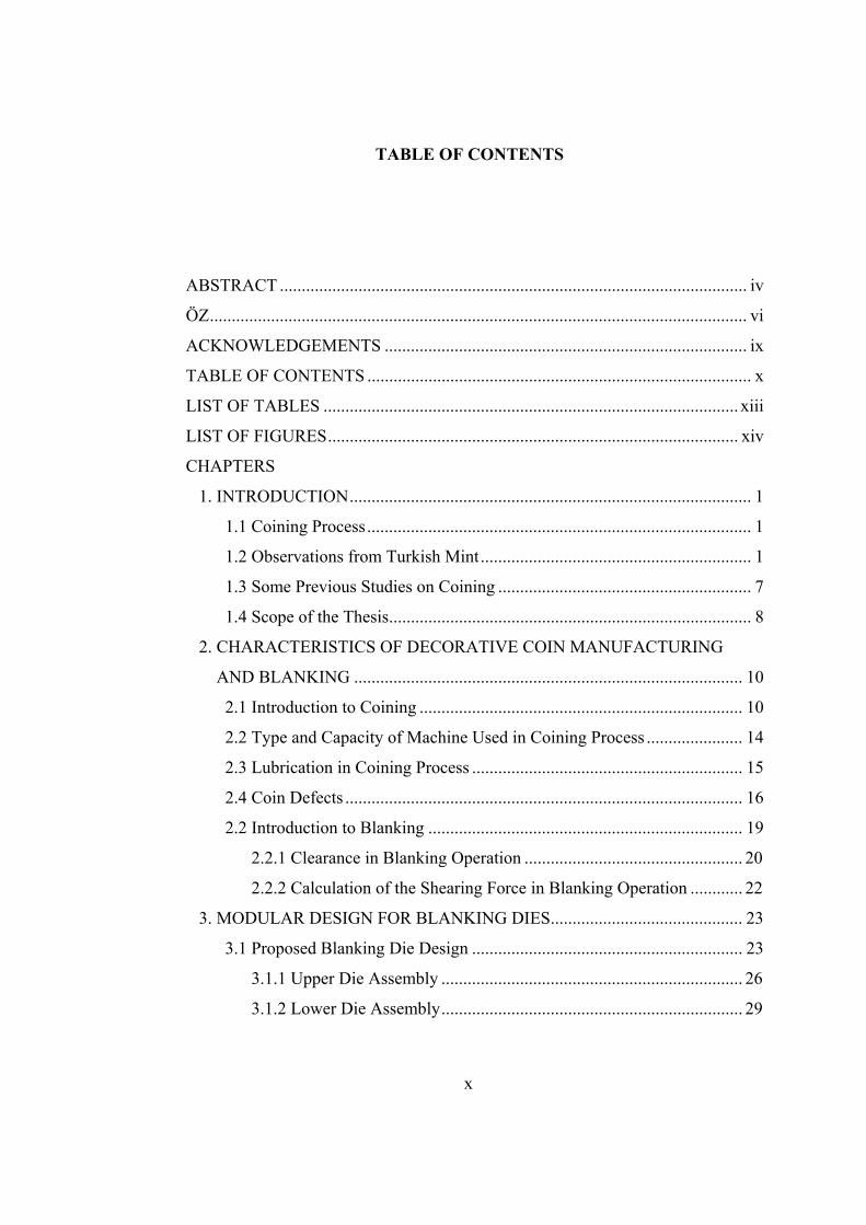
TABLE OF CONTENTS
ABSTRACT ........................................................................................................... iv
ÖZ ........................................................................................................................... vi
ACKNOWLEDGEMENTS ................................................................................... ix
TABLE OF CONTENTS ........................................................................................ x
LIST OF TABLES ............................................................................................... xiii
LIST OF FIGURES .............................................................................................. xiv
CHAPTERS
1. INTRODUCTION ............................................................................................ 1
1.1 Coining Process ........................................................................................ 1
1.2 Observations from Turkish Mint .............................................................. 1
1.3 Some Previous Studies on Coining .......................................................... 7
1.4 Scope of the Thesis ................................................................................... 8
2. CHARACTERISTICS OF DECORATIVE COIN MANUFACTURING
AND BLANKING ......................................................................................... 10
2.1 Introduction to Coining .......................................................................... 10
2.2 Type and Capacity of Machine Used in Coining Process ...................... 14
2.3 Lubrication in Coining Process .............................................................. 15
2.4 Coin Defects ........................................................................................... 16
2.2 Introduction to Blanking ........................................................................ 19
2.2.1 Clearance in Blanking Operation .................................................. 20
2.2.2 Calculation of the Shearing Force in Blanking Operation ............ 22
3. MODULAR DESIGN FOR BLANKING DIES ............................................ 23
3.1 Proposed Blanking Die Design .............................................................. 23
3.1.1 Upper Die Assembly ..................................................................... 26
3.1.2 Lower Die Assembly ..................................................................... 29
xi
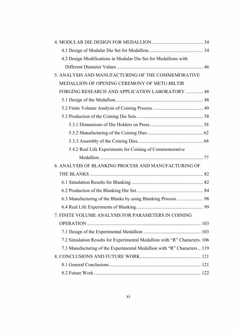
4. MODULAR DIE DESIGN FOR MEDALLION ........................................... 34
4.1 Design of Modular Die Set for Medallion .............................................. 34
4.2 Design Modifications in Modular Die Set for Medallions with
Different Diameter Values ........................................................................ 46
5. ANALYSIS AND MANUFACTURING OF THE COMMEMORATIVE
MEDALLION OF OPENING CEREMONY OF METU-BILTIR
FORGING RESEARCH AND APPLICATION LABORATORY ............... 48
5.1 Design of the Medallion ......................................................................... 48
5.2 Finite Volume Analysis of Coining Process .......................................... 49
5.3 Production of the Coining Die Sets ........................................................ 58
5.3.1 Dimensions of Die Holders on Press ............................................. 58
5.3.2 Manufacturing of the Coining Dies ............................................... 62
5.3.3 Assembly of the Coining Dies ....................................................... 68
5.4.2 Real Life Experiments for Coining of Commemorative
Medallion ....................................................................................... 77
6. ANALYSIS OF BLANKING PROCESS AND MANUFACTURING OF
THE BLANKS ............................................................................................... 82
6.1 Simulation Results for Blanking ............................................................ 82
6.2 Production of the Blanking Die Set ........................................................ 84
6.3 Manufacturing of the Blanks by using Blanking Process ...................... 98
6.4 Real Life Experiments of Blanking ........................................................ 99
7. FINITE VOLUME ANALYSIS FOR PARAMETERS IN COINING
OPERATION ............................................................................................... 103
7.1 Design of the Experimental Medallion ................................................ 103
7.2 Simulation Results for Experimental Medallion with “R” Characters . 106
7.3 Manufacturing of the Experimental Medallion with “R” Characters ... 119
8. CONCLUSIONS AND FUTURE WORK................................................... 121
8.1 General Conclusions ............................................................................. 121
8.2 Future Work ......................................................................................... 122
xii
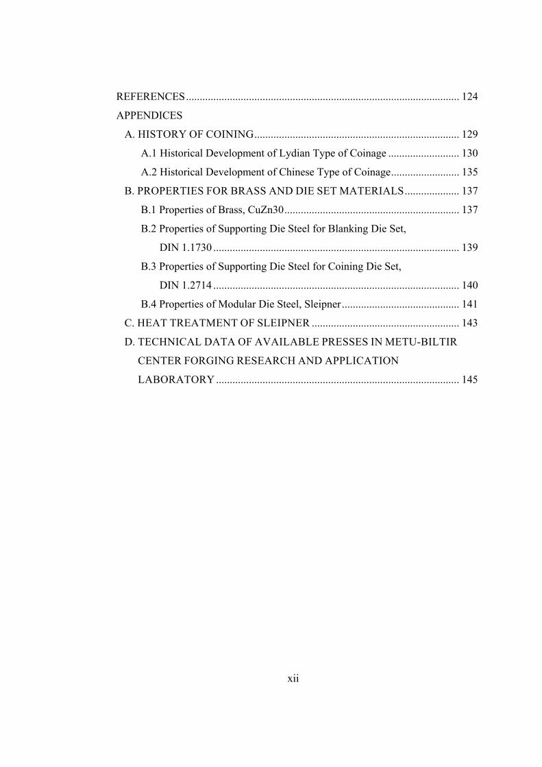
REFERENCES .................................................................................................... 124
APPENDICES
A. HISTORY OF COINING ........................................................................... 129
A.1 Historical Development of Lydian Type of Coinage .......................... 130
A.2 Historical Development of Chinese Type of Coinage ......................... 135
B. PROPERTIES FOR BRASS AND DIE SET MATERIALS .................... 137
B.1 Properties of Brass, CuZn30 ................................................................ 137
B.2 Properties of Supporting Die Steel for Blanking Die Set,
DIN 1.1730 .......................................................................................... 139
B.3 Properties of Supporting Die Steel for Coining Die Set,
DIN 1.2714 .......................................................................................... 140
B.4 Properties of Modular Die Steel, Sleipner ........................................... 141
C. HEAT TREATMENT OF SLEIPNER ...................................................... 143
D. TECHNICAL DATA OF AVAILABLE PRESSES IN METU-BILTIR
CENTER FORGING RESEARCH AND APPLICATION
LABORATORY ......................................................................................... 145
xiii
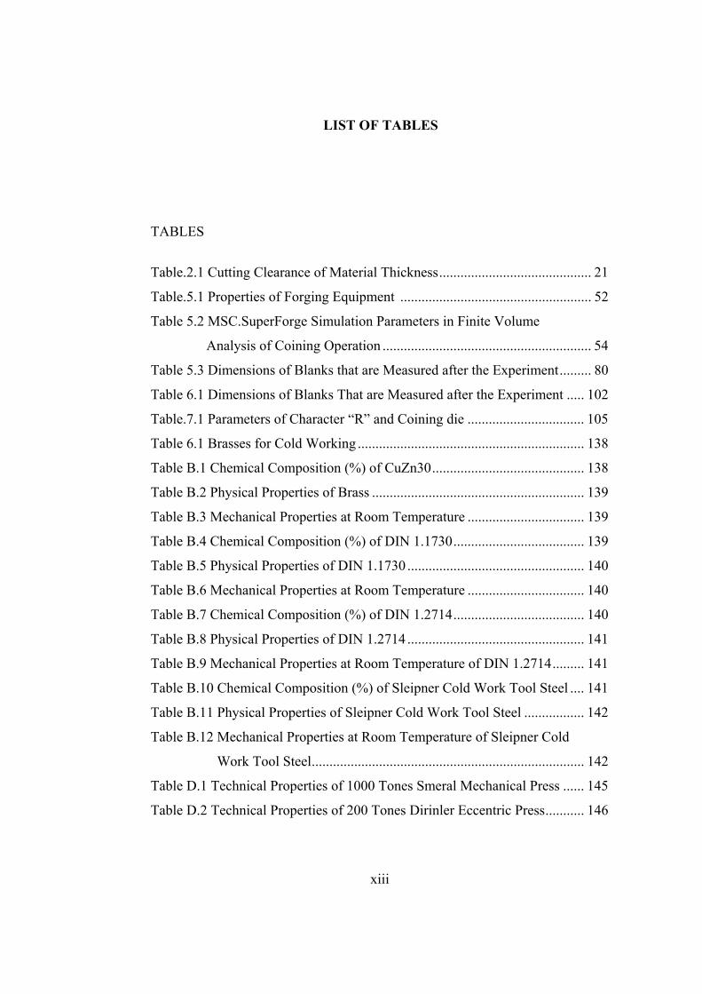
LIST OF TABLES
TABLES
Table.2.1 Cutting Clearance of Material Thickness ........................................... 21
Table.5.1 Properties of Forging Equipment ...................................................... 52
Table 5.2 MSC.SuperForge Simulation Parameters in Finite Volume
Analysis of Coining Operation ........................................................... 54
Table 5.3 Dimensions of Blanks that are Measured after the Experiment ......... 80
Table 6.1 Dimensions of Blanks That are Measured after the Experiment ..... 102
Table.7.1 Parameters of Character “R” and Coining die ................................. 105
Table 6.1 Brasses for Cold Working ................................................................ 138
Table B.1 Chemical Composition (%) of CuZn30 ........................................... 138
Table B.2 Physical Properties of Brass ............................................................ 139
Table B.3 Mechanical Properties at Room Temperature ................................. 139
Table B.4 Chemical Composition (%) of DIN 1.1730 ..................................... 139
Table B.5 Physical Properties of DIN 1.1730 .................................................. 140
Table B.6 Mechanical Properties at Room Temperature ................................. 140
Table B.7 Chemical Composition (%) of DIN 1.2714 ..................................... 140
Table B.8 Physical Properties of DIN 1.2714 .................................................. 141
Table B.9 Mechanical Properties at Room Temperature of DIN 1.2714 ......... 141
Table B.10 Chemical Composition (%) of Sleipner Cold Work Tool Steel .... 141
Table B.11 Physical Properties of Sleipner Cold Work Tool Steel ................. 142
Table B.12 Mechanical Properties at Room Temperature of Sleipner Cold
Work Tool Steel ............................................................................. 142
Table D.1 Technical Properties of 1000 Tones Smeral Mechanical Press ...... 145
Table D.2 Technical Properties of 200 Tones Dirinler Eccentric Press ........... 146
xiv
LIST OF FIGURES
FIGURES
Figure 1.1 The Transference of the Plaster Sketch to Gypsum Mold. ................. 2
Figure 1.2 The Transference of the Gypsum Mold to Acrylic Male. ................... 2
Figure 1.3 The Mechanical Engraving Machine. ................................................. 3
Figure 1.4 The CNC Engraving Machine ............................................................ 4
Figure 1.5 Coin Strike Operation ......................................................................... 6
Figure 2.1 The Main Parts of a Coin. ................................................................. 11
Figure 2.2 Schematic Representation of the Die Setup Utilized for Coin and
Medal Production .............................................................................. 12
Figure 2.3 Sample of Coin with Wrong Blank ................................................... 17
Figure 2.4 Sample of Coin with Mistrike ........................................................... 17
Figure 2.5 Sample of Coin with Cud .................................................................. 17
Figure 2.6 Sample of Coin with Clashed Dies ................................................... 18
Figure 2.7 Sample of Coin with Clipped Blank ................................................. 18
Figure 2.8 Sample of Coin with Double Strike .................................................. 19
Figure 2.9 Sample of Coin with a Second Blow in the Right Edge ................... 19
Figure 2.10 Blanking Process ............................................................................. 20
Figure 2.13 Clearance in Shearing ..................................................................... 21
Figure 3.1 Blanking Die Set ............................................................................... 24
Figure 3.2 Performing the Blanking ................................................................... 25
Figure 3.3 Assembly of Upper Die Set .............................................................. 26
Figure 3.4 Upper Supporting Die ....................................................................... 27
Figure 3.5 Upper Die Support ............................................................................ 27
xv
Figure 3.6 Fixed Component of Upper Die ........................................................ 28
Figure 3.7 Interchangeable Component of Upper Die ....................................... 28
Figure 3.8 Upper Die Assembly ......................................................................... 29
Figure 3.9 Lower Die Assembly ........................................................................ 30
Figure 3.10 Guide Plate ...................................................................................... 31
Figure 3.11 Lower Supporting Die ..................................................................... 31
Figure 3.12 Key Position of Lower Die Assembly ............................................ 32
Figure 3.13 Dimensions of Sheet Material ......................................................... 33
Figure 4.1 Modular Coining Die Set for a Medallion with the Diameter of
90 mm ................................................................................................ 35
Figure 4.2 3-D Model of Upper Coining Supporting Die .................................. 36
Figure 4.3 3-D Model of Upper Coining Die Assembly .................................... 36
Figure 4.4 3-D Model of Coining Lower Die .................................................... 37
Figure 4.5 3-D Model of Lower Supporting Die ................................................ 37
Figure 4.6 Working Principle of Coining Die Set .............................................. 39
Figure 4.7 Die Set after Coining Process ........................................................... 40
Figure 4.8 Upper Die Assembly ......................................................................... 40
Figure 4.9 Exploded View of Upper Die Assembly .......................................... 41
Figure 4.10 Upper Die Assembly ....................................................................... 42
Figure 4.11 Upper Die Assembly ....................................................................... 42
Figure 4.12 Lower Die Assembly ...................................................................... 43
Figure 4.13 Exploded View of Lower Die Assembly ........................................ 43
Figure 4.14 3D Model of Lower Die and Lower Supporting Die ...................... 44
Figure 4.15 Key Position of Lower Die Assembly ............................................ 45
Figure 4.16 Ejection of Medallion from the Lower Die Assembly .................... 45
Figure 4.17 Assembly of Die Set for Coin Diameter of 70 mm ........................ 47
Figure 4.18 Assembly of Die Set for Coin Diameter of 50 mm ........................ 47
Figure 5.1 3-D Model of the Medallion ............................................................. 49
Figure 5.2 MSC.SuperForge Assembly for Coining Operation ......................... 51
xvi
Figure 5.3 Mechanical Properties of Workpiece Material (CuZn30) ................ 52
Figure 5.4 Parameters for Mechanical Press in the Software ............................. 53
Figure 5.5 The Velocity of the Mechanical Crank Press as a Function of Time 54
Figure 5.6 Die Contact (Die Filling) Simulation Steps of the Coin ................... 56
Figure 5.7 Effective Stress Distribution in the Blank with a Diameter of
89 mm ................................................................................................ 57
Figure 5.8 Effective Plastic Strain Distribution in the Blank with a Diameter
of 89 mm ............................................................................................ 57
Figure 5.9 A view of Smeral 1000-ton Mechanical Press in METU-BILTIR
Center Forging Research and Application Laboratory ...................... 58
Figure 5.10 Shut Height and Die Holder of Smeral 1000-ton Mechanical
Pres .................................................................................................. 59
Figure 5.11 A view of Lower Die Holder .......................................................... 60
Figure 5.12 Top view of the Circular Dies ......................................................... 61
Figure 5.13 Front view of the Circular Dies ...................................................... 61
Figure 5.14 Technical Drawing of the Interchangeable Part of Upper Coining
Die ................................................................................................... 63
Figure 5.15 A view of Manufactured Interchangeable Part of Upper Coining
Die ................................................................................................... 63
Figure 5.16 Technical Drawing of the Upper Coining Supporting Die ............. 64
Figure 5.17 A view of Manufactured Upper Coining Supporting Die ............... 64
Figure 5.18 Technical Drawing of the Fixed Part of Upper Coining Die .......... 65
Figure 5.19 A view of Manufactured Fixed Part of Upper Coining Die ............ 65
Figure 5.20 Technical Drawing of the Lower Coining Die ............................... 66
Figure 5.21 A view of Manufactured Lower Die of Coining Die Set ................ 66
Figure 5.22 Technical Drawing of the Lower Coining Supporting Die ............. 67
Figure 5.23 A view of Manufactured Lower Coining Supporting Die .............. 67
Figure 5.24 A view of Upper Coining Die Assembly Parts ............................... 68
Figure 5.25 A view of Lower Coining Die Assembly Parts .............................. 68
xvii
Figure 5.26 Assembly of Supporting Die and Fixed Part of the Upper
Coining Die ...................................................................................... 69
Figure 5.27 Locations of the Clamping Parts of Upper Coining Die Set ........... 70
Figure 5.28 A view of Manufactured Lower Coining Die Assembly ................ 70
Figure 5.29 A view of Manufactured Lower Coining Die Assembly with
the Rectangular Key ........................................................................ 71
Figure 5.30 Locations of the Moving Parts of Lower Coining Die Set ............. 71
Figure 5.31 Technical Drawing of the Pin ......................................................... 72
Figure 5.32 Technical Drawing of the Ejector Pin ............................................. 72
Figure 5.33 Technical Drawing of the Upper Die Key ...................................... 73
Figure 5.34 Technical Drawing of the Lower Coining Die Key ........................ 73
Figure 5.35 Lower Die Key, Pin, Bolts and Ejector for Coining Die Set .......... 73
Figure 5.36 A view of Mounted Coining Dies on the Press............................... 74
Figure 5.37 A view of Assembled Upper Die Set .............................................. 75
Figure 5.38 A view of Die Sets before the Coinage ........................................... 75
Figure 5.39 Schematic Illustration of Cutting Dimensions of Sheet Metal for
W-EDM ........................................................................................... 76
Figure 5.40 Circular Blanks Manufactured with W-EDM ................................. 77
Figure 5.41 A view of the Blank on the Lower Supporting Die ........................ 77
Figure 5.42 A view of Die Sets after the Coinage .............................................. 78
Figure 5.43 A view of Coined Medallion without Polishing and Varnishing .... 78
Figure.5.44. A view of Polished and Varnished Coined Medallion ................... 79
Figure 6.45 Measurement Points after Blanking ................................................ 79
Figure 6.1 MSC.SuperForge Assembly for Blanking Operation ....................... 82
Figure 6.2 Effective Stress Distribution for Blanks ........................................... 83
Figure 6.3 Cross Section of Effective Stress Distribution for Blanks ................ 83
Figure 6.4 Effective Plastic Strain Distribution for Blanks ................................ 84
Figure 6.5 A view of Dirinler 200-ton Eccentric Press in METU-BILTIR
Center Forging Research and Application Laboratory ...................... 85
xviii
Figure 6.6 Technical Drawing of the Upper Blanking Supporting Die ............. 87
Figure 6.7 Technical Drawing of the Interchangeable Component of Upper
Blanking Die ...................................................................................... 87
Figure 6.8 A view of Manufactured Upper Blanking Supporting Die ............... 88
Figure 6.9 A view of Manufactured Interchangeable Component of Blanking
Upper Die .......................................................................................... 88
Figure 6.10 Technical Drawing of the Interchangeable Component of Upper
Blanking Die .................................................................................... 89
Figure 6.11 A view of Manufactured Fixed Component of Blanking Upper
Die ................................................................................................... 89
Figure 6.12 Technical Drawing of the Upper Die Support of Blanking Die
Set .................................................................................................... 90
Figure 6.13 A view of Manufactured Upper Die Support of Blanking Die Set . 90
Figure 6.14 Technical Drawing of the Guide Plate of Blanking Die Set ........... 91
Figure 6.15 A view of Manufactured Guide Plate of Blanking Die Set ............ 91
Figure 6.16 Technical Drawing of the Lower of Blanking Die ......................... 92
Figure 6.17 Technical Drawing of the Lower Blanking Supporting Die ........... 92
Figure 6.18 A view of Manufactured Lower Blanking Die ............................... 93
Figure 6.19 A view of Manufactured Lower Blanking Supporting Die ............ 93
Figure 6.20 A view of Upper Blanking Die Assembly ...................................... 94
Figure 6.21 A view of Lower Blanking Die Assembly ...................................... 94
Figure 6.22 Views of Manufactured Components of the Upper Blanking Die
Assembly ........................................................................................ 95
Figure 6.23 Exploded view of Manufactured Lower Blanking Die Assembly .. 95
Figure 6.24 Bolt for Fixing Interchangeable Upper Die to Fixed Die Upper
Die ................................................................................................... 96
Figure 6.25 A view of Assembly of the Blanking Die Set ................................. 96
Figure 6.26 A view of Assembled Upper Die Set .............................................. 97
Figure 6.27 A view of Assembled Lower Die Set ............................................. 97
xix
Figure 6.28 Modular Blanking Die Set .............................................................. 98
Figure 6.29 Schematic Illustration of Dimensions of Strips cut from Sheet
Metal .............................................................................................. 100
Figure 6.30 a view of Die Sets during Blanking .............................................. 100
Figure 6.31 A view of Blank ............................................................................ 101
Figure 6.32 Measurement Points after Blanking .............................................. 101
Figure 7.1 3-D Model of the Medallion ........................................................... 104
Figure 7.2 Lines of Relief with Respect to Parameters .................................... 104
Figure 7.3 coining Die Parameters ................................................................... 105
Figure 7.4 The Character Height ...................................................................... 105
Figure 7.5 Cu-Zn Phase Diagram ..................................................................... 106
Figure 7.5 Die Contact (Die Filling) Simulation Steps at 20°C with 0.5 mm
Facial Clearance in Cavity Zone ..................................................... 107
Figure 7.6 Effective Stress Distribution at 20°C with 0.5 mm Facial
Clearance in Cavity Zone ................................................................ 108
Figure 7.7 Effective Plastic Strain Distribution at 20°C with 0.5 mm Facial
Clearance in Cavity Zone ................................................................ 108
Figure 7.8 Die Contact (Die Filling) Simulation Steps at 20°C with 1.0 mm
Facial Clearance in Cavity Zone ..................................................... 109
Figure 7.9 Effective Stress Distribution at 20°C with 1.0 mm Facial
Clearance in Cavity Zone ................................................................ 110
Figure 7.10 Effective Plastic Strain Distribution at 20°C with 1.0 mm Facial
Clearance in Cavity Zone .............................................................. 110
Figure 7.11 Die Contact (Die Filling) Simulation Steps at 400°C with 0.5 mm
Facial Clearance in Cavity Zone ................................................... 111
Figure 7.12 Effective Stress Distribution at 400°C with 0.5 mm Facial
Clearance in Cavity Zone .............................................................. 112
Figure 7.13 Effective Plastic Strain Distribution at 400°C with 0.50 mm
Facial Clearance in Cavity Zone ................................................... 112

xx
Figure 7.14 Die Contact (Die Filling) Simulation Steps at 400°C with
1.0 mm Facial Clearance in Cavity Zone ...................................... 113
Figure 7.15 Effective Stress Distribution at 400°C with 1.0 mm Facial
Clearance in Cavity Zone ............................................................. 114
Figure 7.16 Effective Plastic Strain Distribution at 400°C with 1.0 mm
Facial Clearance in Cavity Zone ................................................... 114
Figure 7.17 Die Contact (Die Filling) Simulation Steps at 800°C with
0.5 mm Facial Clearance in Cavity Zone ..................................... 115
Figure 7.18 Effective Stress Distribution at 800°C with 0.5 mm Facial
Clearance in Cavity Zone ............................................................. 116
Figure 7.19 Effective Plastic Strain Distribution at 800°C with 0.5 mm
Facial Clearance in Cavity Zone ................................................... 116
Figure 7.20 Die Contact (Die Filling) Simulation Steps at 800°C with
1.0 mm Facial Clearance in Cavity Zone ...................................... 117
Figure 7.21 Effective Stress Distribution at 800°C with 1.0 mm Facial
Clearance in Cavity Zone .............................................................. 118
Figure 7.22 Effective Plastic Strain Distribution at 800°C with 1.0 mm
Facial Clearance in Cavity Zone ................................................... 118
Figure 7.23 Manufactured Interchangeable Upper Die for Blanking Die Set .. 119
Figure 7.24 Manufactured Interchangeable Upper Die Set for Experimental
Medallion ....................................................................................... 120
Figure 7.25 Mounted Coining Die Set for Experimental Medallion on Press . 120
Figure A.1 The Earliest Coins of World Lydia with Lydian Lion ................... 130
Figure A.2 The most Common Ancient China coins ....................................... 130
Figure A.3 Schematic illustration of The Earliest Coining Process. ................ 132
Figure A.4 The Portrait Lathe or Pantograph ................................................... 135
Figure C.1 Applied Heat Treatment Process .................................................... 144
CHAPTER 1
INTRODUCTION
1.1 Coining Process
Coining is used to produce decorative items such as coins, medallions, patterned
tableware, metal buttons and other products where exact size, fine details and
also tight tolerances are required in a product. When articles with a design and a
polished surface are required, coining is the only practical production method to
use [1,2].
The process is a closed-die forging operation generally performed at the room
temperature by means of a positive displacement punch while the metal is
completely confined within a set of dies. The metal forming operation in which
the material is displaced in a small amount compared to the total volume of the
part is also called coining [1]. History of coining is provided in Appendix A.
1.2 Observations from Turkish Mint
The Turkish Mint in Istanbul was visited and the conventional coining process
was carefully observed by the author. In Turkish Mint, in order to form a
decorative coin, token or a medallion, many operations are applied in different
workshops. Firstly at Art Workshop, the sculptor and a design team conduct a
study which includes history and important items of the occasional event or
gathering information about the person for whom the coin will be made for.
After preparations are completed, the design is sketched with a certain larger
scale on paper by the sculptor. The design team determines the most appropriate
1
design as designated the shape considering different type of alternatives of the
coin or medallion that is being worked on. After that, the sketch is engraved on
plaster that is easy to change its shape after drying and to adjust its hardness.
Then the work on plaster is transferred to gypsum which is used as positive
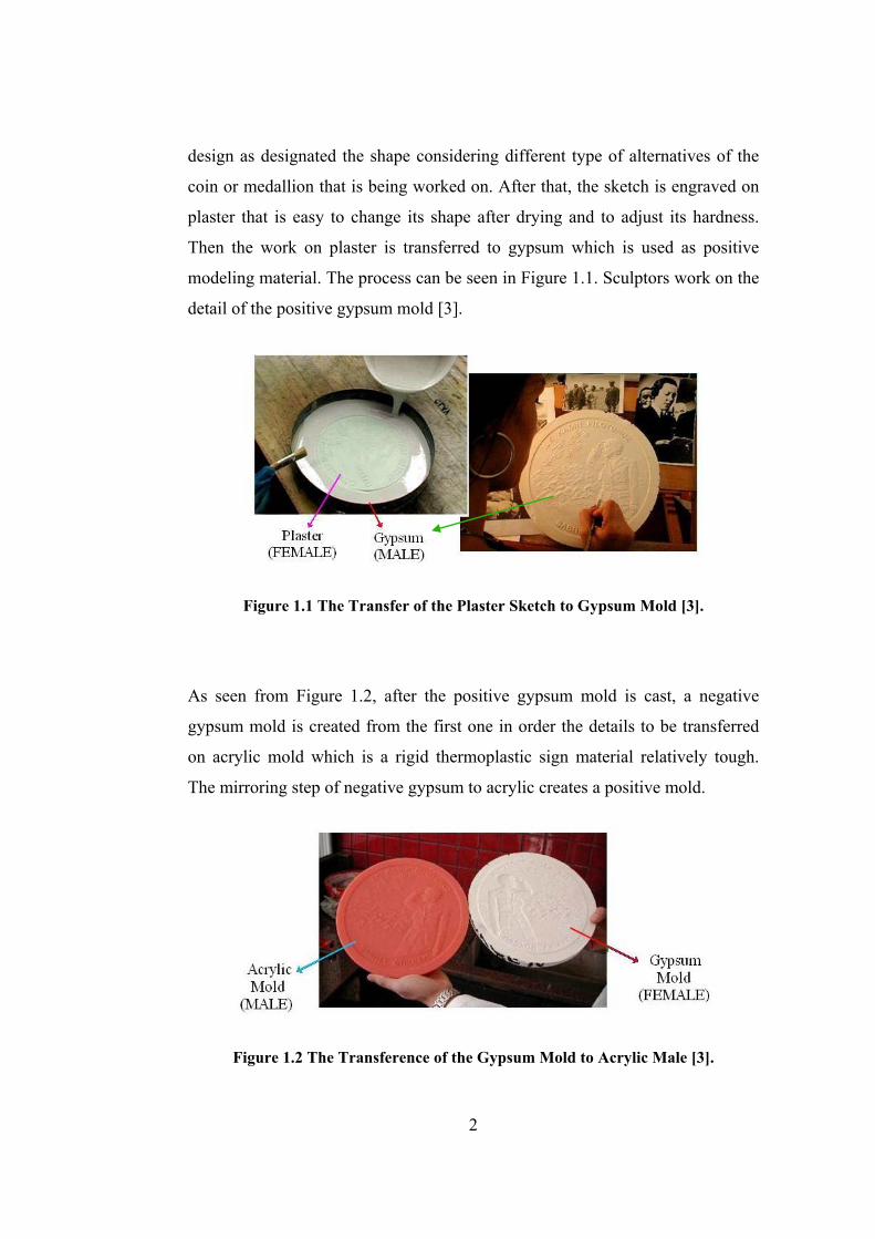
modeling material. The process can be seen in Figure 1.1. Sculptors work on the
detail of the positive gypsum mold [3].
Figure 1.1 The Transfer of the Plaster Sketch to Gypsum Mold [3].
As seen from Figure 1.2, after the positive gypsum mold is cast, a negative
gypsum mold is created from the first one in order the details to be transferred
on acrylic mold which is a rigid thermoplastic sign material relatively tough.
The mirroring step of negative gypsum to acrylic creates a positive mold.
Figure 1.2 The Transference of the Gypsum Mold to Acrylic Male [3].
2
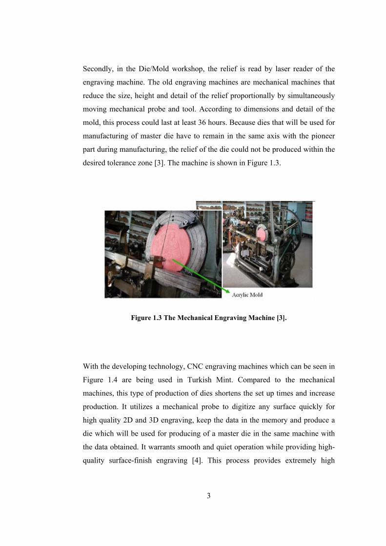
Secondly, in the Die/Mold workshop, the relief is read by laser reader of the
engraving machine. The old engraving machines are mechanical machines that
reduce the size, height and detail of the relief proportionally by simultaneously
moving mechanical probe and tool. According to dimensions and detail of the
mold, this process could last at least 36 hours. Because dies that will be used for
manufacturing of master die have to remain in the same axis with the pioneer
part during manufacturing, the relief of the die could not be produced within the
desired tolerance zone [3]. The machine is shown in Figure 1.3.
Figure 1.3 The Mechanical Engraving Machine [3].
With the developing technology, CNC engraving machines which can be seen in
Figure 1.4 are being used in Turkish Mint. Compared to the mechanical
machines, this type of production of dies shortens the set up times and increase
production. It utilizes a mechanical probe to digitize any surface quickly for
high quality 2D and 3D engraving, keep the data in the memory and produce a
die which will be used for producing of a master die in the same machine with
the data obtained. It warrants smooth and quiet operation while providing high-
quality surface-finish engraving [4]. This process provides extremely high
3
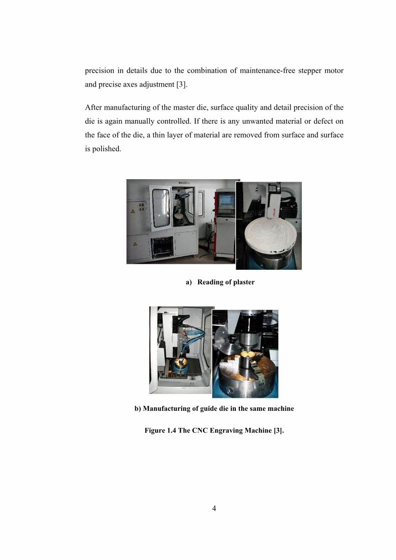
precision in details due to the combination of maintenance-free stepper motor
and precise axes adjustment [3].
After manufacturing of the master die, surface quality and detail precision of the
die is again manually controlled. If there is any unwanted material or defect on
the face of the die, a thin layer of material are removed from surface and surface
is polished.
a) Reading of plaster
b) Manufacturing of guide die in the same machine
Figure 1.4 The CNC Engraving Machine [3].
4

A master die is produced from the reduction punch using a cold forging process
called hobbing. This is achieved by pressing the design into another piece of soft
steel using very high forces in a hydraulic press. This master die is then
hardened and used in the same way to produce a ‘positive’ tool called a hob or
hub [5].
An electro-plating process is applied to the tool to deposit hard chromium on the
surface of the die to reduce wear in the coining process and to extend the life of
the dies. Afterwards, dies to be used in minting are manufactured according to
master die details and brought to the desired hardness by heat treatment. As a
last process polishing is done on the dies that will be used in mintage.
Firstly in the mint, alloy material is cast and rolled to the desired thickness or
purchased from the suppliers. Blanks are cut from the rolled metal alloy, which
usually consists of a mixture of base metals. The composition of these alloys is
carefully controlled.
During the rolling, work hardening is naturally applied to the blank metal.
Before the coinage, the blanks need to be softened slightly in a furnace by bring
blanks up to a certain temperature and then cooling them again. This provides
metal to relieve thermal stresses. After annealing, the blanks are burnished to
make their surface brighter, remove any discoloration and in some cases apply a
minute amount of lubricant to assist in coining. In the burnishing machine,
surfaces of blanks are etched and polished by tumbling inside a mixture of small
steel balls and ceramic media combined with special chemicals. After
burnishing, the blanks are dried with hot air.
The web sites of Australian Mint have also been examined [5].
After blanks are prepared; they may be fed automatically into the tungsten
carbide collars. The collar which can be seen in Figure 1.5 locates the blank
prior to striking and controls the finished size and shape of the edge of the coin.
If notch shape is wanted on the outside of the coin to be formed, collar which
5

has the mirrored notches is used. To produce the obverse and reverse designs,
the blank is struck simultaneously with two dies during coining. This edge detail
is transferred to the workpiece by first machining the retaining ring and then
coining. While mounting the dies, upper and lower dies should be properly
aligned. Otherwise, coining defects may be encountered.
Several different types of coining presses are operated for general circulating
coins. The coining capacity of these presses ranges from 100 to 500 tones force.
The choice of press depends on the size and alloy (metal) of the struck coin. The
larger the coin and harder the metal, the more pressure required, which usually
means a slower strike rate. Defected blanks are automatically rejected by the
press without slowing down the production process.
Figure 1.5 Coin Strike Operation [5]
During the striking, generally no lubricant is used because lubricant can be
struck between the die and blank and form a dip called surface pocket.
Therefore, this formation affects the surface quality and internal stresses inside
the dies [6].
6
Coins are first counted electronically to control whether the last product is
below from the accepted standards. After bagging, are weighed as an additional
check.
1.3 Some Previous Studies on Coining
Some previous studies have been conducted on coining. Choi, et. al. [7]
developed a finite-element analysis program using the rigid–plastic method for
process design in three-dimensional plastic deformation. Applying the
developed program to a precision-coining process, the amount of deformation
was obtained.
To produce a smaller and more functional precision electrical component in the
electronic guns of TV tube, Byun, Huh and Kang [8] developed a multi-
operation process sequence improving the conventional manufacturing. Finite
element method was used for the design and analysis of the developed process.
By conducting a series of experimental forming, numerical results are validated
by using precision measurement techniques.
Ike [9] has studied the fundamental effects on the formation of surface
microgeometry in coining process. The local contact pressure, bulk plasticity,
combined stresses and relative sliding on the forming surface can be counted as
the major factors. Experimental productions have been done for the effects
separately and compared with the data on literature so that the results were in
the acceptable range.
Wang, et. al. [10] coined the pure aluminum to monitor the effects of die cavity
dimension on the microforming ability of various microparts in the production
of micro electro mechanical systems (MEMS). The results of the experimental
production can be evaluated with the use of the grain structure of the
microforming billets. According to well-produced microgears which were soon
heat treated, it was seen that small die details could be completely formed.
7
Choi, Kim and Kang [11] has applied precision coining operation to develop the
finite element method called backward tracing scheme in which forward loading
simulation and backward tracing of a rigid plastic forming operation in the three
dimensional metal forming. During the experimental coinage, the shape and
location of the central piercing hole was examined. Results showed that the
geometrical tolerances of the production were reasonable and the method could
be used in industrial applications easily.
Thome, Hirt and Rattay [12] have studied the sheet metal production by means
of coining process to design and support the geometrical properties of dies.
Considering the dies separate, forming as inserts, instead of one-pieced dies, the
relation between geometric characteristics of the tools and finished product was
analyzed. In the analyses, the comparison factor was the coining force levels.
Davis, et. al. [13] evaluated and improved the current coining process in which a
one-dimensional sinusoidal shape is coined onto a thin circular blank so that
presses were used feasibly. With the new technique developed, finite element
simulations were stated and a coining tool were designed and manufactured. By
means of this mechanism, alternative materials were tested and a sample of
special nuclear material was coined as the experimental study.
1.4 Scope of the Thesis
The conventional coin production is very challenging procedure considering the
formation of surface details and transference of the detailed shape from sketch
which is the design on the paper to master dies. It requires tight dimensions and
tolerances as well as a proper way of micro production. However, transferring
design by multistage operation is time consuming and there is an increase of
tolerance values all along the production line.
8
The design of medallions and coins are still performed by sketching the paper
and transferring to the dies by several intermediate steps in mints. This time
consuming procedure results in material waste and time consumption.
The scope of this study is to analyze the coining process, to introduce an
alternative method which includes CAD/CAM applications to the design and
production phases and to introduce modular design for both blanking and
coinage dies. In this study, coining process of the commemorative medallion of
the opening ceremony of METU-BILTIR Center is designed and produced.
Basic principles of coining and blanking will be given in Chapter 2 to provide a
basis for the study.
In the study, the modular dies for both blanking stage and coining process will
given in Chapter 3 and Chapter 4 in the order.
In Chapter 5, finite volume analysis for manufacturing of commemorative
medallion of the opening ceremony of METU-BILTIR Center Forging Research
and Application Laboratory will be presented. In this chapter, there will be also
production of the modular coining die set and the medallion.
Current production of modular blanking die set and blanks will be given in
detail in Chapter 6. In the same chapter, finite volume analysis of the proposed
procedure for blanking will also be given.
The details of modeling, simulation and manufacturing of an experimental coin
for observe the parameters of coining process will be given in Chapter 7.
Conclusion, discussion and recommendations for the future work will be given
in Chapter 8.
9
CHAPTER 2
CHARACTERISTICS OF DECORATIVE COIN MANUFACTURING
AND BLANKING
2.1 Introduction to Coining
The word “coin” derives from Latin cuneus, meaning wedge or punch, and a
literal meaning of the word coin would be something that has been struck. But
this definition would exclude modern coinage as well as ancient Chinese iron
coins that were cast rather than struck. A satisfactory, if somewhat restrictive
definition would be a round, flat piece of some recognized metal bearing the
stamp of an issuing authority to guarantee its weight, fineness or value [14].
Minting is the process of transferring a design with relief features from a die
onto a blank piece of metal.
Coins have a special terminology. To clarify the terminology, a sample coin is
shown in Figure 2.1. The terms that are stated below can be generalized for all
coins and medallions.
• Obverse (Head): the front or heads side of a coin or medal; generally
bearing the date, mint mark, allegorical figure and main design.
• Reverse (Tail): Reverse is the back or tail side of a coin or medal
regarded as of lesser importance. In the 1800's obverse and reverse
meant the opposite of what they mean today [15].
• Relief: The part of the design that is raised from the surface of the coin
is denoted as relief which is the opposite of incuse.
• Edge: Edge is the outer border of a coin; it can be also considered as the
third side of the coin. On some coin edges, there may be letters, reeds
10

which is an edge with small lines on it, ornamental designs or plain
edges. This part is formed with the design of collar.
• Rim: Rim is the raised edge on both sides of a coin. The idea being that
if the edge on both sides of the coin is raised like the design it will help
protect the coins design from wear.
• Field: The background portion of a coin's surface which is not used for
design or inscription is called the field.
• Legend: Legend is the main lettering on a coin.
• Mint mark: Usually there is an additional small letter on a coin which
denotes the place of minting. This letter is referred as the mint mark.
Figure 2.1 The Main Parts of a Coin [16].
In addition to the above terminology items, for some coins “incuse” may exist.
Incuse is rather than the coin's design being raised up off of the surface of the
coin, it is pressed into the metal as cavity.
In closed-die coining, all surfaces of a prepared blank is compressed between
the coining dies while it is retained and positioned between the dies by a ring or
collar, resulting a well-defined imprint of the die on the workpiece. It is also a
11
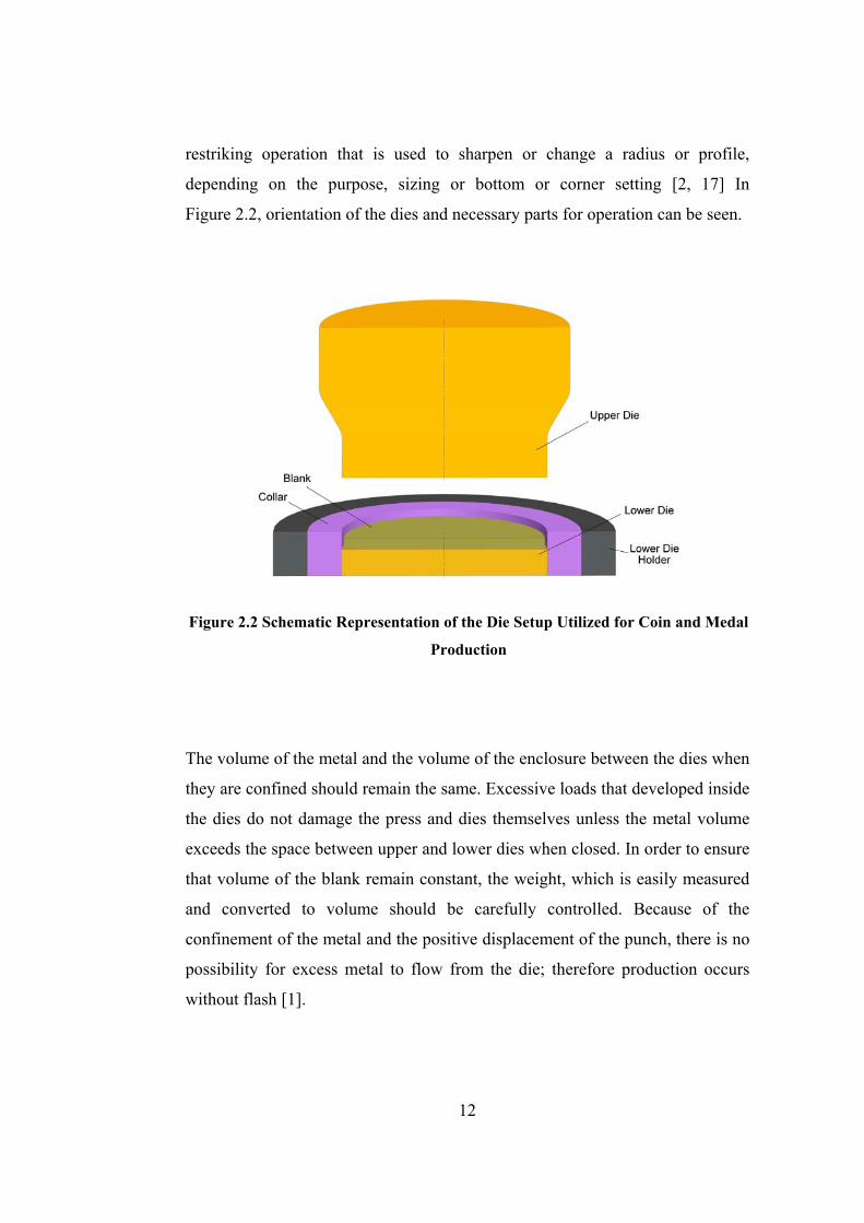
restriking operation that is used to sharpen or change a radius or profile,
depending on the purpose, sizing or bottom or corner setting [2, 17] In
Figure 2.2, orientation of the dies and necessary parts for operation can be seen.
Figure 2.2 Schematic Representation of the Die Setup Utilized for Coin and Medal
Production
The volume of the metal and the volume of the enclosure between the dies when
they are confined should remain the same. Excessive loads that developed inside
the dies do not damage the press and dies themselves unless the metal volume
exceeds the space between upper and lower dies when closed. In order to ensure
that volume of the blank remain constant, the weight, which is easily measured
and converted to volume should be carefully controlled. Because of the
confinement of the metal and the positive displacement of the punch, there is no
possibility for excess metal to flow from the die; therefore production occurs
without flash [1].
12
Generally, after production of definite number of coins, approximately 300,000,
there is a possibility of die wear. To enable an effective production, die dressing
is required to be minimized, keeping the relief of the coin design low.
Compressive work hardening of the metal ensures the coin to have good wear
resistance. Raising the edge of the coin, also called as milled edge, prevents the
wear of the coin face.
A typical coining manufacturing operation has the procedure as follows:
• Blanking of coin disks from sheet metal is performed with surface finish
and thickness that is determined for coin.
• The disks are barrel tumbled to deburr so that desirable surface finish
and to control weight can be achieved.
• The disks are fed to the press.
• With the movement of the upper or lower die rather than by use of a
conventional ejector. The coins are ejected from the retaining ring.
In the coinage, these steps can also be used for the processing of medallions,
with some additional processes. Unless the design details are in high relief,
edging operations are not required in production of medallions. In such a case,
the full development of details may require restriking [2].
Since strain hardening occurs very quickly, only relatively thin annealed parts
which have Brinell hardness value smaller than 100 can be produced in a single
operation in cold coining process. Inside the cavity of coining dies, the prepared
blank is loaded above the compressive yield strength and is held in this
condition during coining. Dwell time under load is important for the
development of dimensions in sizing and embossing; it is also necessary for the
reproduction of fine detail, as in engraving [2].
Since coining process has a close relation with common hardness test, the
required forces which start the initiation of cracks are well known. Practical
limits on workpiece size are mainly determined by available press capacities and
13

properties of the die material. Any contour on the blank can be formed by a
certain amount of pressure on the projected area depending on the mechanical
properties of the material and depth of indentations. The magnitude of this
certain pressure varies between 500 and 3000 times the Brinell hardness or two
and five times the tensile or compressive strength of the metal. For example,
work metal with a compressive yield strength of 690 MPa loaded in a press of
22 MN capacity can be coined in a maximum surface area of 0.032 m2. From the
stress formula, as the yield strength increases, the area that can be coined using
the same press decreases proportionately. However, an increase in strength of
the workpiece should be limited so that plastic deformation of the die does not
take place [1-2].
In coining process, the extruded projections are limited as to their minimum
cross-sectional area and the minimum radii at their ends since producing a sharp
design on either the raised surface portion or on the edge of a coined part
requires very high pressures. In addition, during the deformation, the average
thickness of a coined part should be restricted and should be kept nearly
constant and not vary greatly from the edge to the center [1].
2.2 Type and Capacity of Machine Used in Coining Process
In coining, the workpiece is squeezed between the dies so that the entire surface
area is simultaneously loaded above the yield strength. Because of the area
loading requirement and the great stress needed to ensure metal movement,
press loading for coining is frequently approach the capacity of the equipment
used, with consequent danger of overloading.
Some coining equipment, such as drop hammers, cannot be readily overloaded.
If a mechanical press is used in order to perform the coining process, an amount
of stroke which is slightly more than the stroke that is necessary to fill the die
cavity produces large pressures which may result in a failure in the tools and the
equipment. This is most likely to happen if more than one blank is fed to the
14
coining dies at a time. Such overloading can break the dies and even the press,
and it will certainly shorten the life of the dies.
Overloading may be prevented by the use of overload release devices, and many
presses are equipped with such devices. However, the usual means for avoiding
excessive pressures and preventing overloading in presses is careful control of
workpiece thickness, which must be sufficient to allow acceptable coining, but
not enough to lead to press overloading. Such thickness control, combined with
blank-feeding procedures designed to minimize double blanking, is normally
adequate to prevent overloading.
Coining may be satisfactorily undertaken in any type of press that has the
required capacity. However, the flow of metal during the coining is
accomplished during a relatively short portion of the stroke, so that a coining
load is required only during a small portion of the press cycle. Drop hammers,
and knuckle-type and eccentric-driven mechanical presses are extensively used
in coining. High-speed hydraulic presses also are well adapted for coining,
especially when progressive dies are used. Large-capacity hydraulic presses are
ideal for coining and sizing operations on large workpieces [1,2].
2.3 Lubrication in Coining Process
Whenever possible, lubricant is not preferred in coining operations. If entrapped
in the coining dies, lubricant cause flaws in the surface. These struck lubricant
particles are called lubricant pocket and they prevents the material to entirely fill
the mating die covering the surface of the recesses and reproduction of fine die
surface details. As dies get together, metal cannot be squeezed out of the die.
For example, under conditions of constrained plastic flow, an entrapped
lubricant will be loaded in hydrostatic compression and will interfere with the
transfer of die detail to the workpiece. In many coining operations, however,
because of work metal composition or the severity of coining, or both, the use of
15
some lubricant is mandatory to prevent defects or seizing of the dies and the
work metal [1,2].
No lubricant is used for coining teaspoons, medallions, or similar items where
the high surface quality is required. Some type of lubricant is ordinarily used for
coining copper and aluminum and their alloys and for coining stainless, alloy,
and carbon steels. When coining intricate designs, such as the design on the
handles of stainless steel teaspoons, the lubricant must be used sparingly. A film
of soap solution is usually sufficient. Excessive amounts of lubricant adversely
affect workpiece finish and interfere with transfer of the design [2].
2.4 Coin Defects
With uniform designs, the exact replication of the official design is not so easy
to achieve. Despite the objective of complete uniformity, variations do occur.
Varieties can originate from just about any stage of the minting process and
errors of the stages.
There may be errors during the coining process due to the certain defects in the
blank structure or misadventure during operation. Despite the fact that most
errors can be filtered out by post strike inspection, an error coin may still get
missed and pass into circulation. Some of the errors can be stated as follows:
• Brockage
• Mistrike
• Cud
• Clashed dies
• Clipped blank
• Double strike
• Mule
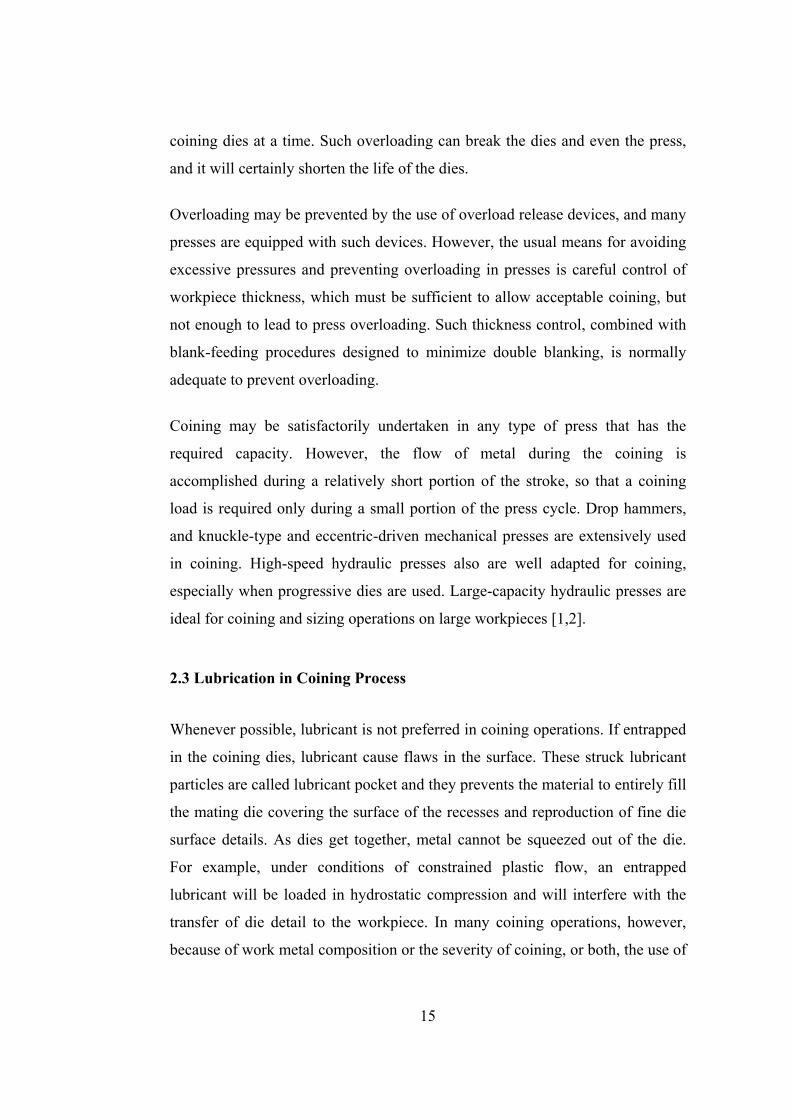
Wrong blank can be described as a brockage that is formed when a coin is not
ejected from the press and remains in place while another blank is struck. The
16
result is that the first coin acts as a die for the second one and makes an incuse
impression of the exposed face. Image that can be seen in Figure 2.3 is of a
hollow face.
Figure 2.3 Sample of Coin with Wrong Blank [18]
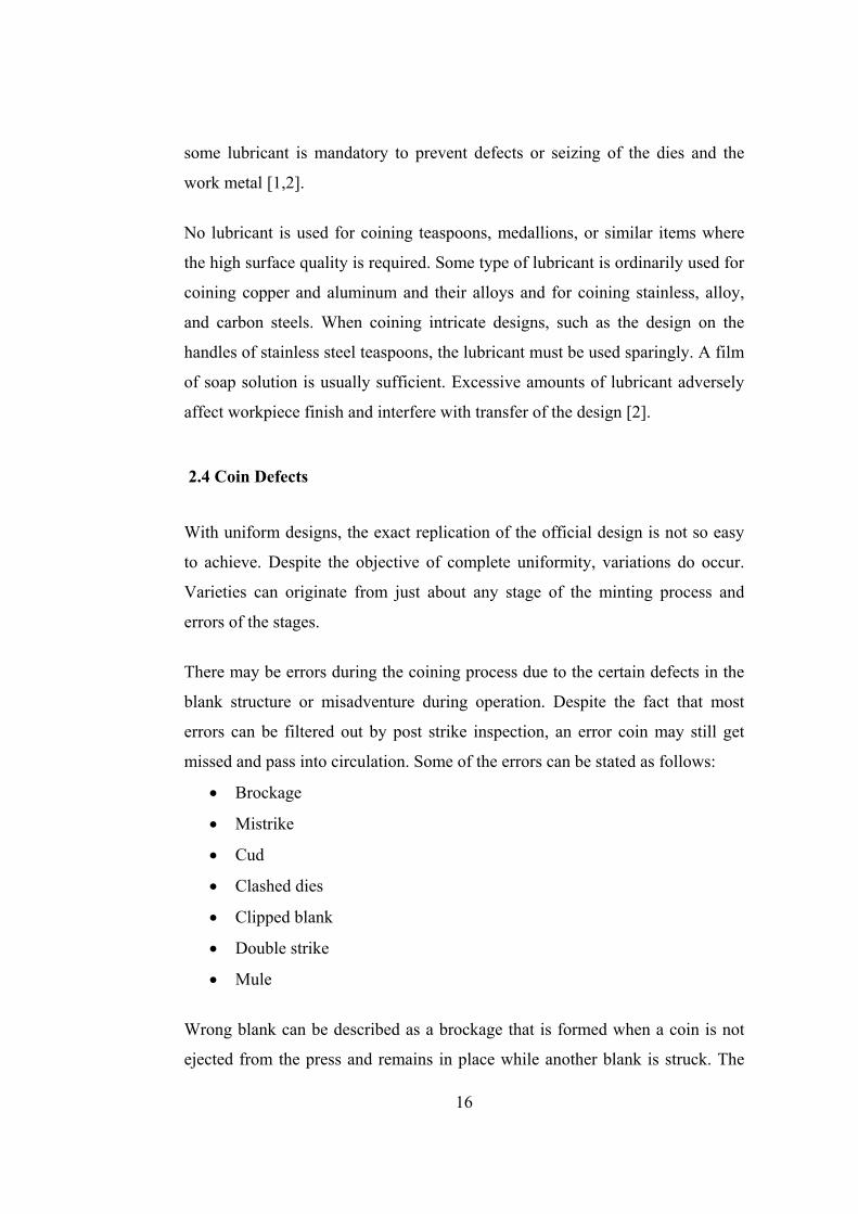
Mistrike is a fairly common error in which the blank has not engaged properly
in the collar and so is struck off-centre which can be seen in Figure 2.4. In order
the coin to be minted without this defect, blank should be located concentrically
in the dies.
Figure 2.4 Sample of Coin with Mistrike [18]
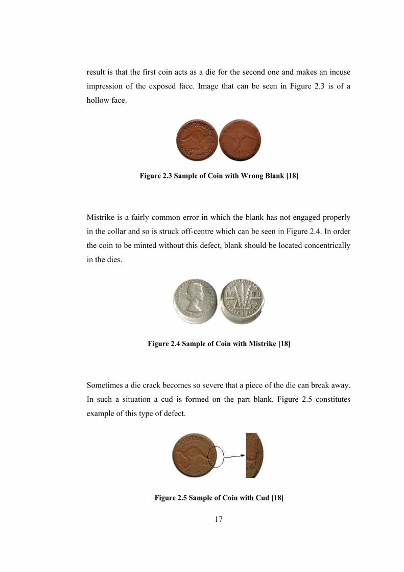
Sometimes a die crack becomes so severe that a piece of the die can break away.
In such a situation a cud is formed on the part blank. Figure 2.5 constitutes
example of this type of defect.
Figure 2.5 Sample of Coin with Cud [18]
17
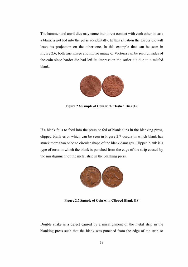
The hammer and anvil dies may come into direct contact with each other in case
a blank is not fed into the press accidentally. In this situation the harder die will
leave its projection on the other one. In this example that can be seen in
Figure 2.6, both true image and mirror image of Victoria can be seen on sides of
the coin since harder die had left its impression the softer die due to a misfed
blank.
Figure 2.6 Sample of Coin with Clashed Dies [18]
If a blank fails to feed into the press or fed of blank slips in the blanking press,
clipped blank error which can be seen in Figure 2.7 occurs in which blank has
struck more than once so circular shape of the blank damages. Clipped blank is a
type of error in which the blank is punched from the edge of the strip caused by
the misalignment of the metal strip in the blanking press.
Figure 2.7 Sample of Coin with Clipped Blank [18]
Double strike is a defect caused by a misalignment of the metal strip in the
blanking press such that the blank was punched from the edge of the strip or
18

delay of the removal of the coined blank. An example of the defect can be seen
in Figure 2.8.
Figure 2.8 Sample of Coin with Double Strike [18]
After the first strike, if a coin cannot be fully ejected from the reach of the dies,
the metal partly remain in the incidence of the dies. In the continuing strikes, the
coin subsequently received a second blow which can be seen in Figure 2.9.
Figure 2.9 Sample of Coin with a Second Blow in the Right Edge [18]
2.2 Introduction to Blanking
Blanking is a shearing process wherein the shearing blades take the form of
closed, curved lines on the edges of a punch and die. In blanking process, the
primary sheet metal falls out as scrap and the punched part remains dropping
through the die as the desired workpiece [19]. The illustration in Figure 2.10
shows a typical blanking process.
19
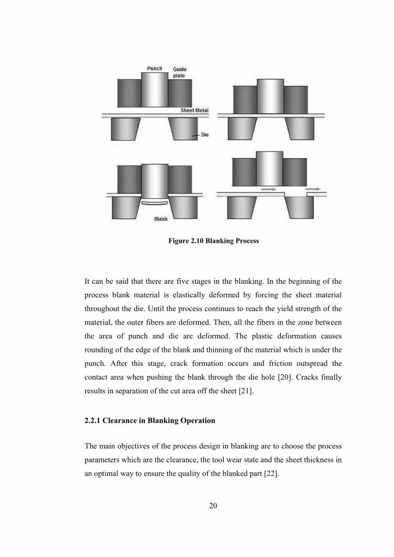
Figure 2.10 Blanking Process
It can be said that there are five stages in the blanking. In the beginning of the
process blank material is elastically deformed by forcing the sheet material
throughout the die. Until the process continues to reach the yield strength of the
material, the outer fibers are deformed. Then, all the fibers in the zone between
the area of punch and die are deformed. The plastic deformation causes
rounding of the edge of the blank and thinning of the material which is under the
punch. After this stage, crack formation occurs and friction outspread the
contact area when pushing the blank through the die hole [20]. Cracks finally
results in separation of the cut area off the sheet [21].
2.2.1 Clearance in Blanking Operation
The main objectives of the process design in blanking are to choose the process
parameters which are the clearance, the tool wear state and the sheet thickness in
an optimal way to ensure the quality of the blanked part [22].
20
If correct clearances between the punch and die are chosen, almost perfect edge
surface may be obtained. When the clearance amount increases, excessive burrs
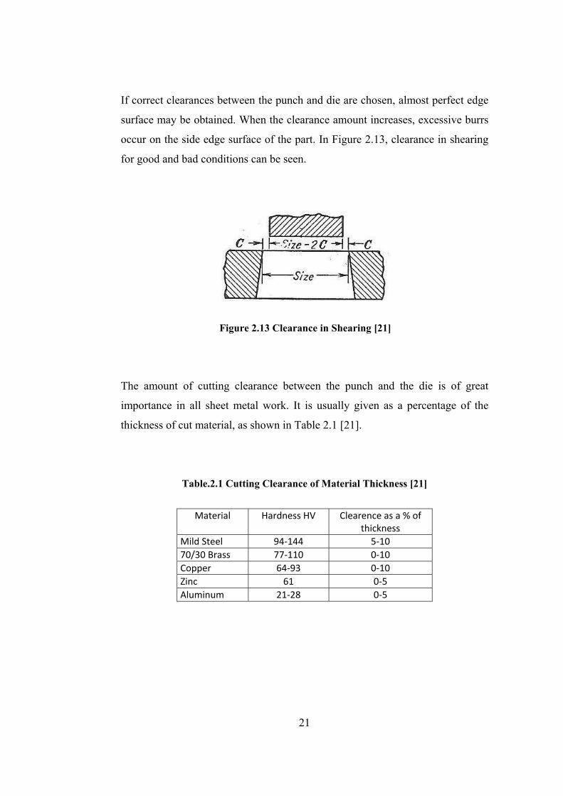
occur on the side edge surface of the part. In Figure 2.13, clearance in shearing
for good and bad conditions can be seen.
Figure 2.13 Clearance in Shearing [21]
The amount of cutting clearance between the punch and the die is of great
importance in all sheet metal work. It is usually given as a percentage of the
thickness of cut material, as shown in Table 2.1 [21].
Table.2.1 Cutting Clearance of Material Thickness [21]
Material Hardness HV Clearence as a % of thickness
Mild Steel 94‐144 5‐10 70/30 Brass 77‐110 0‐10 Copper 64‐93 0‐10 Zinc 61 0‐5 Aluminum 21‐28 0‐5
21
2.2.2 Calculation of the Shearing Force in Blanking Operation
The amount of force needed to produce blanks from the sheet metal has to be
calculated in order to determine the size of a press to use.
At the beginning of the process, the press tonnage should be determined. If a
press has lower tonnage than necessary is chosen, excessive stresses may be
created during the process. With a much more tonnage, extra force will be
inefficient [21].
Tonnage can be simply evaluated by using
(2.1)
where L indicates the total length of a cut, t indicates the material thickness and
SS is the shear strength of the material.
22

CHAPTER 3
MODULAR DESIGN FOR BLANKING DIES
3.1 Proposed Blanking Die Design
Medallions are produced by using blanking and coining processes. Medallions
may have different outer diameters, generally in the range of 30-90 mm. In the
study, a modular die set for producing of the blanks with different outer
diameters has been designed. The blanking die set has mainly 10 components as
seen in Figure 3.1, which are;
• Upper Supporting Die
• Interchangeable Component of Upper Die (i.e. punch)
• Fixed Component of Upper Die (i.e. punch)
• Bolt which fixes Interchangeable Component of Upper Die to Fixed
Component of Upper Die
• Upper Die Support
• Bolts which fix the Upper Support to the Upper Supporting Die
• Guide Plate
• Lower Die
• Lower Supporting Die
• Bolts that fix the Guide Plate to the Lower Supporting Die
As seen from the figure, the upper die can be adopted to the different values of
the diameter of the medallions. This design allows us to produce blanks with the
outer diameter of 30-90 mm by changing the interchangeable component of
upper die, guide plate and lower die.
23
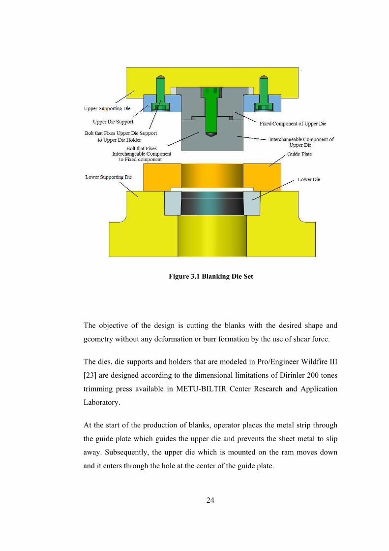
Figure 3.1 Blanking Die Set
The objective of the design is cutting the blanks with the desired shape and
geometry without any deformation or burr formation by the use of shear force.
The dies, die supports and holders that are modeled in Pro/Engineer Wildfire III
[23] are designed according to the dimensional limitations of Dirinler 200 tones
trimming press available in METU-BILTIR Center Research and Application
Laboratory.
At the start of the production of blanks, operator places the metal strip through
the guide plate which guides the upper die and prevents the sheet metal to slip
away. Subsequently, the upper die which is mounted on the ram moves down
and it enters through the hole at the center of the guide plate.
24
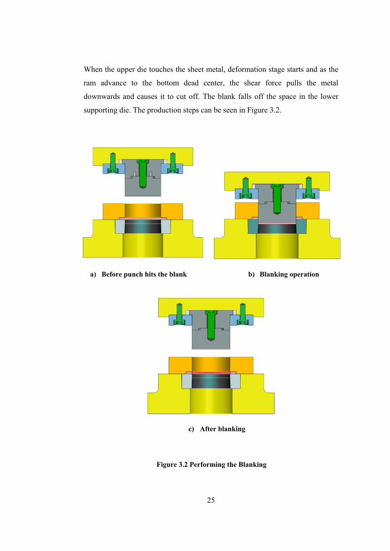
When the upper die touches the sheet metal, deformation stage starts and as the
ram advance to the bottom dead center, the shear force pulls the metal
downwards and causes it to cut off. The blank falls off the space in the lower
supporting die. The production steps can be seen in Figure 3.2.
a) Before punch hits the blank
b) Blanking operation
c) After blanking
Figure 3.2 Performing the Blanking
25
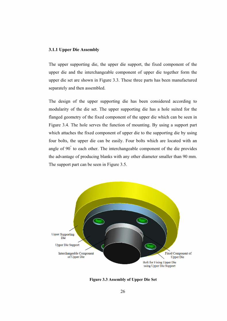
3.1.1 Upper Die Assembly
The upper supporting die, the upper die support, the fixed component of the
upper die and the interchangeable component of upper die together form the
upper die set are shown in Figure 3.3. These three parts has been manufactured
separately and then assembled.
The design of the upper supporting die has been considered according to
modularity of the die set. The upper supporting die has a hole suited for the
flanged geometry of the fixed component of the upper die which can be seen in
Figure 3.4. The hole serves the function of mounting. By using a support part
which attaches the fixed component of upper die to the supporting die by using
four bolts, the upper die can be easily. Four bolts which are located with an
angle of 90° to each other. The interchangeable component of the die provides
the advantage of producing blanks with any other diameter smaller than 90 mm.
The support part can be seen in Figure 3.5.
Figure 3.3 Assembly of Upper Die Set
26
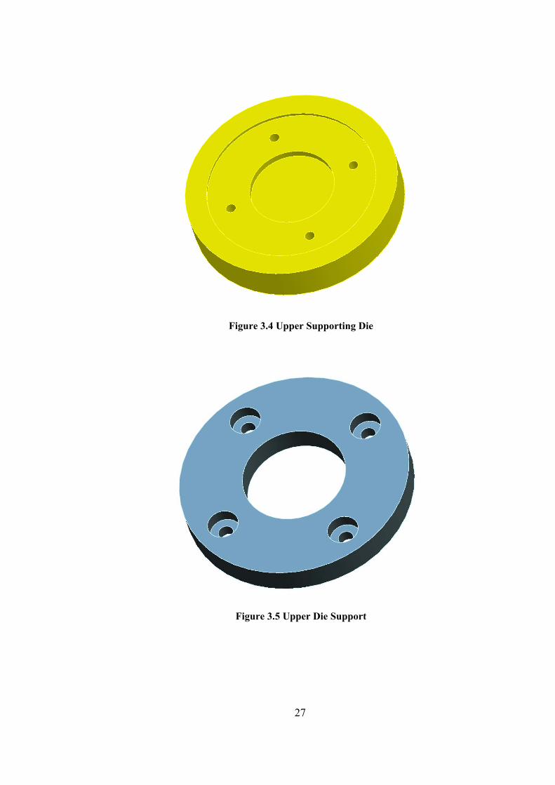
Figure 3.4 Upper Supporting Die
Figure 3.5 Upper Die Support
27
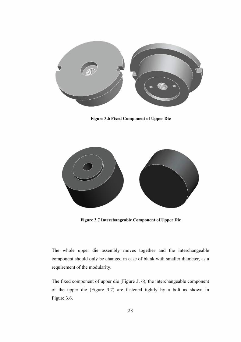
Figure 3.6 Fixed Component of Upper Die
Figure 3.7 Interchangeable Component of Upper Die
The whole upper die assembly moves together and the interchangeable
component should only be changed in case of blank with smaller diameter, as a
requirement of the modularity.
The fixed component of upper die (Figure 3. 6), the interchangeable component
of the upper die (Figure 3.7) are fastened tightly by a bolt as shown in
Figure 3.6.
28
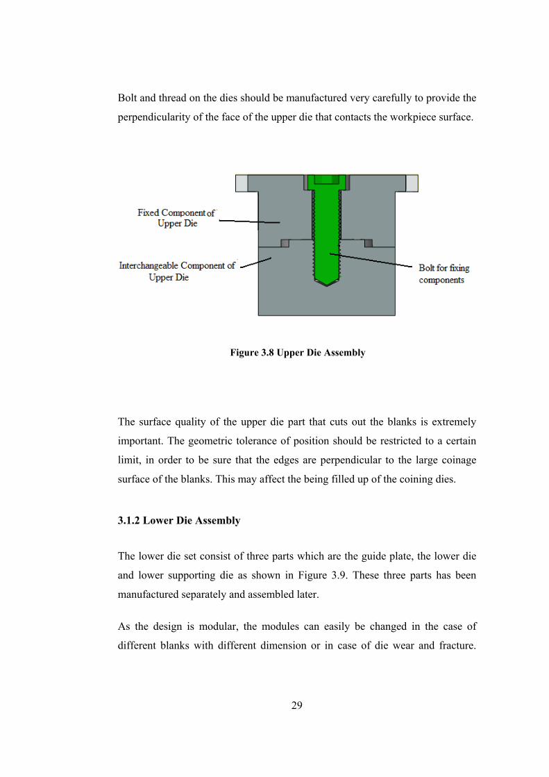
Bolt and thread on the dies should be manufactured very carefully to provide the
perpendicularity of the face of the upper die that contacts the workpiece surface.
Figure 3.8 Upper Die Assembly
The surface quality of the upper die part that cuts out the blanks is extremely
important. The geometric tolerance of position should be restricted to a certain
limit, in order to be sure that the edges are perpendicular to the large coinage
surface of the blanks. This may affect the being filled up of the coining dies.
3.1.2 Lower Die Assembly
The lower die set consist of three parts which are the guide plate, the lower die
and lower supporting die as shown in Figure 3.9. These three parts has been
manufactured separately and assembled later.
As the design is modular, the modules can easily be changed in the case of
different blanks with different dimension or in case of die wear and fracture.
29

Moreover, design modifications can be made by only changing the
interchangeable modules.
The guide plate, which can be seen in Figure 3.10, leads both the upper die and
sheet metal in order to avoid misalignments. As a result, the tolerance values
between guide plate and upper die or workpiece is critical and should be
properly produced. The guide plate attaches the lower die to the lower
supporting die by using four bolts as seen in Figure 3.9. A taper clearance of 2°
is applied for the lower die.
Figure 3.9 Lower Die Assembly
For the mounting of the lower die, the guide part fastened with four bolts. The
lower supporting die can be shown in Figure 3.11. The positions of the die
adjustment bolts are seen in Figure 3.12.
30

Figure 3.10 Guide Plate
Figure 3.11 Lower Supporting Die
31
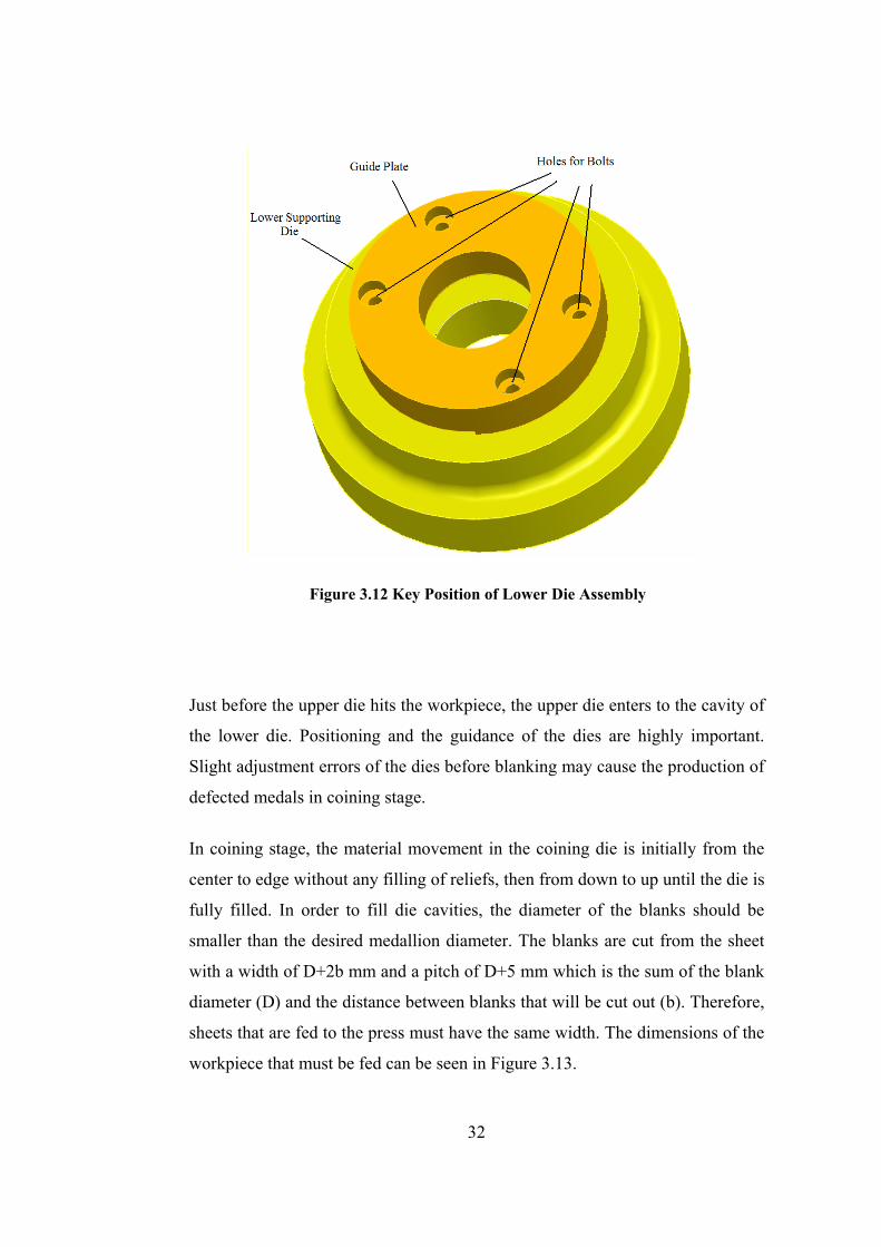
Figure 3.12 Key Position of Lower Die Assembly
Just before the upper die hits the workpiece, the upper die enters to the cavity of
the lower die. Positioning and the guidance of the dies are highly important.
Slight adjustment errors of the dies before blanking may cause the production of
defected medals in coining stage.
In coining stage, the material movement in the coining die is initially from the
center to edge without any filling of reliefs, then from down to up until the die is
fully filled. In order to fill die cavities, the diameter of the blanks should be
smaller than the desired medallion diameter. The blanks are cut from the sheet
with a width of D+2b mm and a pitch of D+5 mm which is the sum of the blank
diameter (D) and the distance between blanks that will be cut out (b). Therefore,
sheets that are fed to the press must have the same width. The dimensions of the
workpiece that must be fed can be seen in Figure 3.13.
32
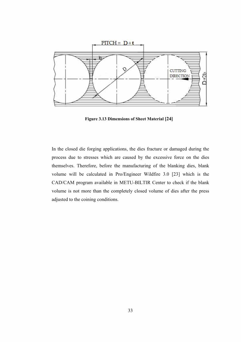
Figure 3.13 Dimensions of Sheet Material [24]
In the closed die forging applications, the dies fracture or damaged during the
process due to stresses which are caused by the excessive force on the dies
themselves. Therefore, before the manufacturing of the blanking dies, blank
volume will be calculated in Pro/Engineer Wildfire 3.0 [23] which is the
CAD/CAM program available in METU-BILTIR Center to check if the blank
volume is not more than the completely closed volume of dies after the press
adjusted to the coining conditions.
33
CHAPTER 4
MODULAR DIE DESIGN FOR MEDALLION
4.1 Design of Modular Die Set for Medallion
A modular die set for the particular coining operation which can be
interchangeable according to the outer diameter of the blank has been designed.
The main objective in the design is to provide a completely closed die operation
which does not allow any excess material to escape outside of the dies so that
avoiding any flash formation.
The proposed coining die set for a medallion with a diameter of 90 mm consists
of 10 parts as seen in Figure 4.1, which are
• Upper Supporting Die
• Interchangeable Component of Upper Die (i.e. punch)
• Fixed Component of Upper Die (i.e. punch)
• Bolt which fixes Interchangeable Component of Upper Die to Fixed
Component of Upper Die
• Keys for stabilizing the fixed Component of the Upper Die
• Pins that adjust the location of the Upper Die
• Lower Die
• Key that adjust the rotational location of the Lower Die
• Lower Supporting Die
• Ejectors
34
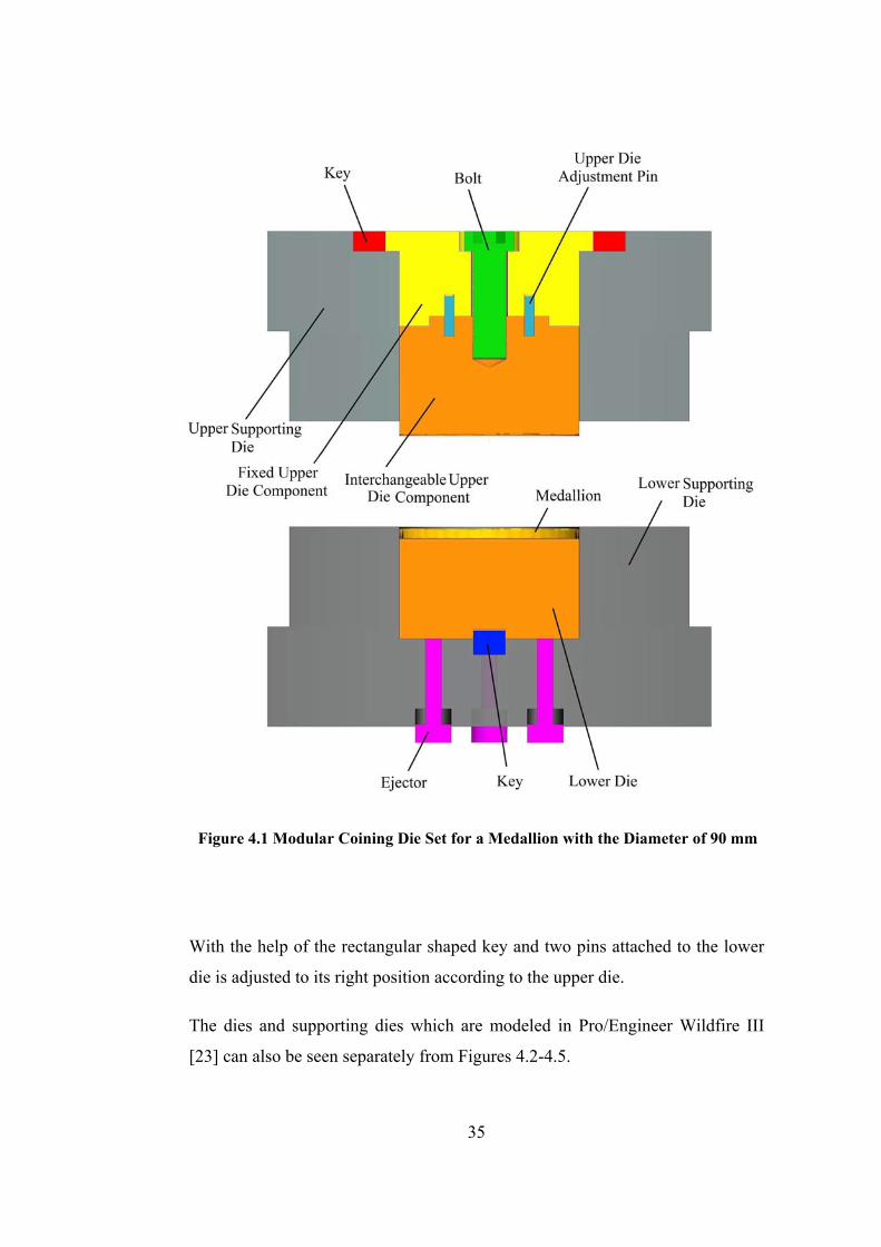
Figure 4.1 Modular Coining Die Set for a Medallion with the Diameter of 90 mm
With the help of the rectangular shaped key and two pins attached to the lower
die is adjusted to its right position according to the upper die.
The dies and supporting dies which are modeled in Pro/Engineer Wildfire III
[23] can also be seen separately from Figures 4.2-4.5.
35
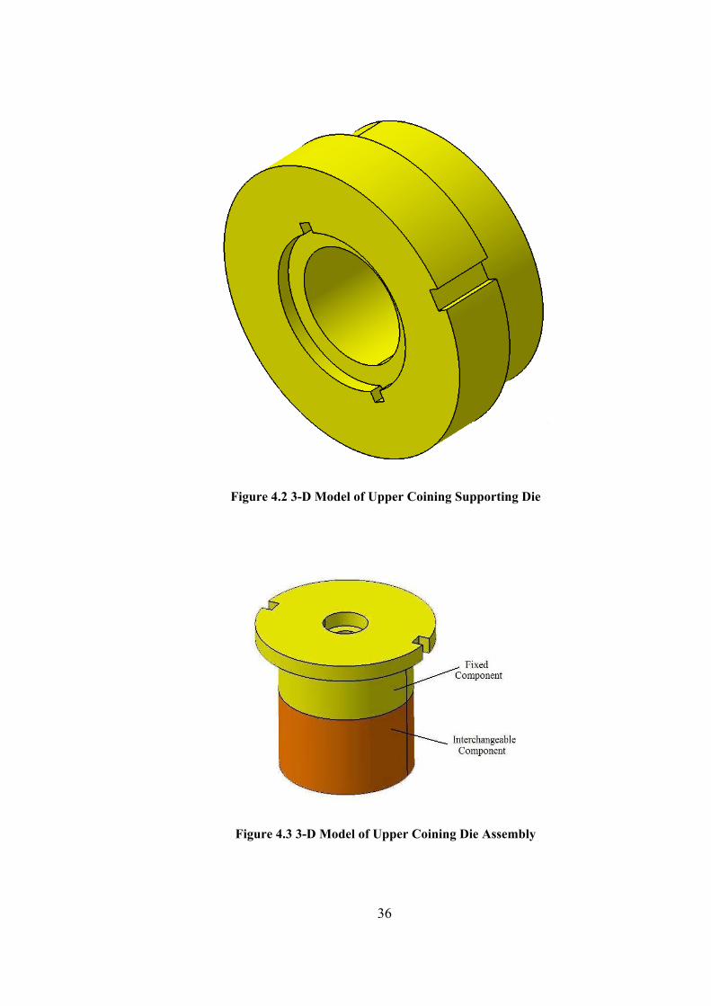
Figure 4.2 3-D Model of Upper Coining Supporting Die
Figure 4.3 3-D Model of Upper Coining Die Assembly
36
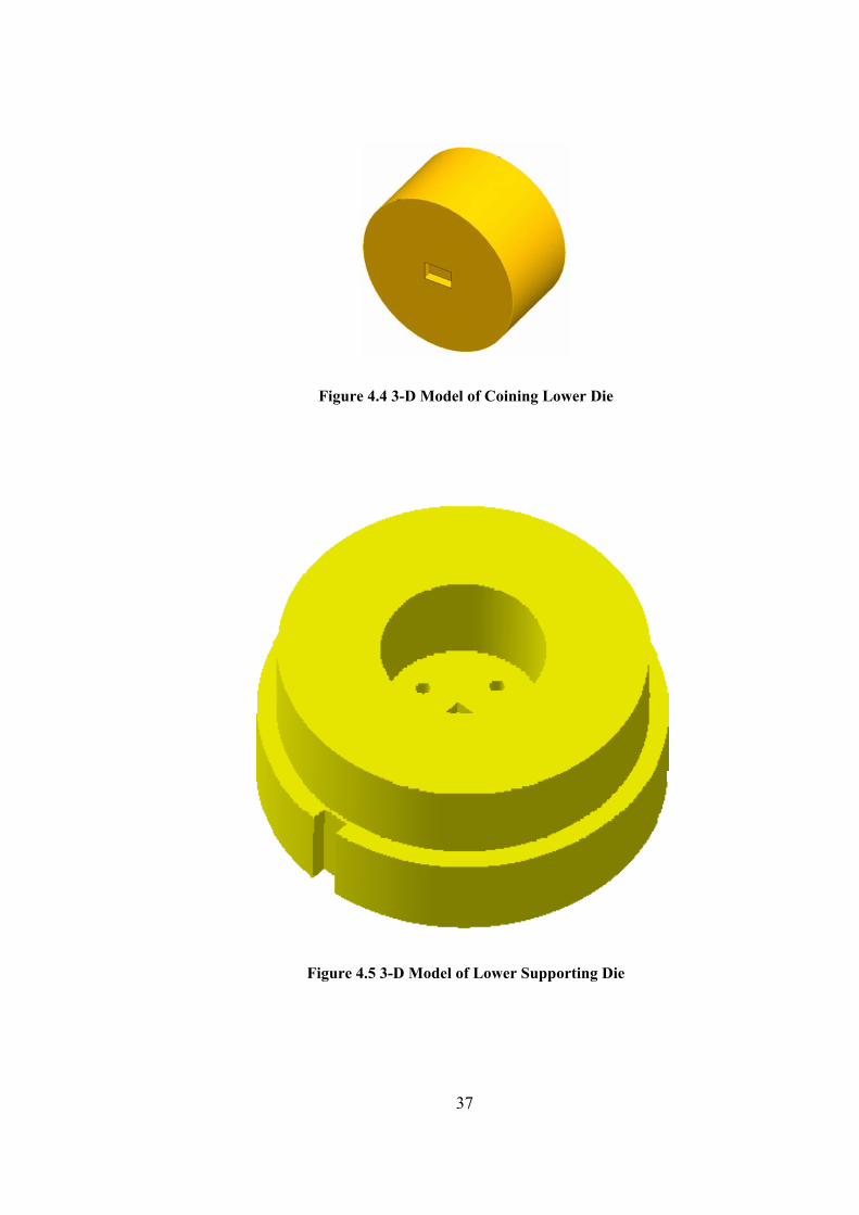
Figure 4.4 3-D Model of Coining Lower Die
Figure 4.5 3-D Model of Lower Supporting Die
37
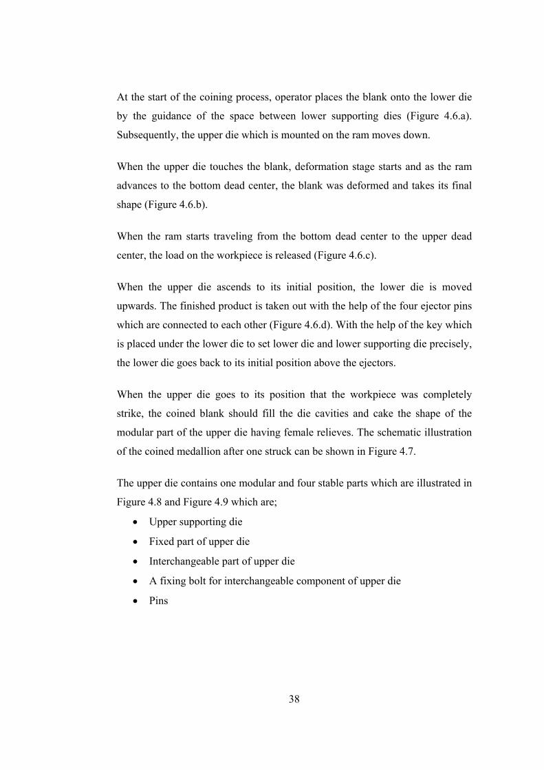
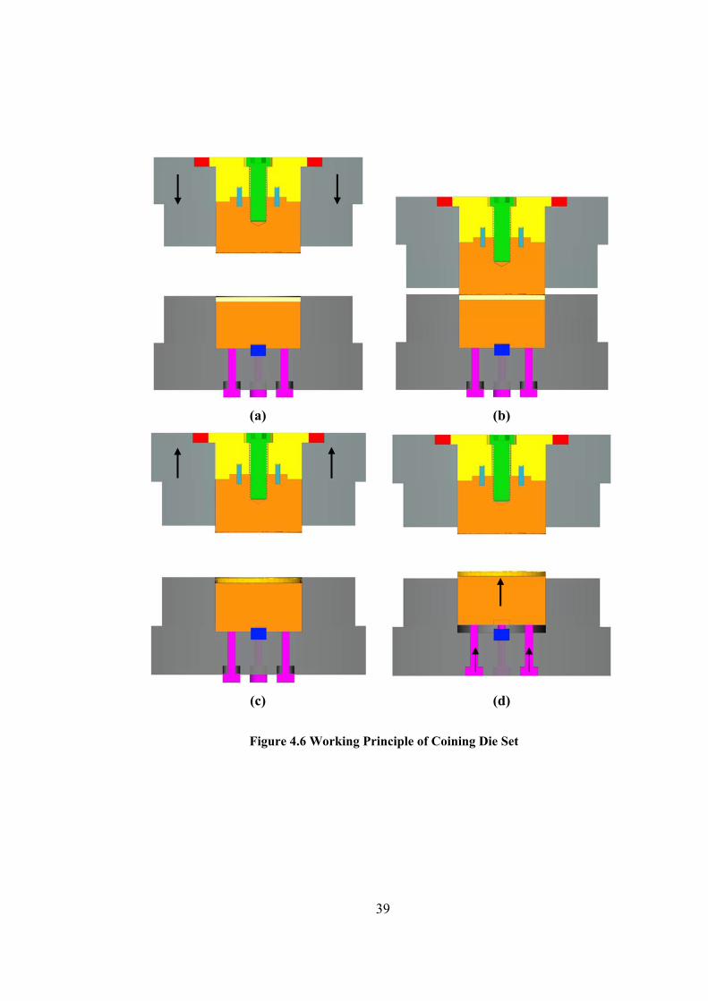
At the start of the coining process, operator places the blank onto the lower die
by the guidance of the space between lower supporting dies (Figure 4.6.a).
Subsequently, the upper die which is mounted on the ram moves down.
When the upper die touches the blank, deformation stage starts and as the ram
advances to the bottom dead center, the blank was deformed and takes its final
shape (Figure 4.6.b).
When the ram starts traveling from the bottom dead center to the upper dead
center, the load on the workpiece is released (Figure 4.6.c).
When the upper die ascends to its initial position, the lower die is moved
upwards. The finished product is taken out with the help of the four ejector pins
which are connected to each other (Figure 4.6.d). With the help of the key which
is placed under the lower die to set lower die and lower supporting die precisely,
the lower die goes back to its initial position above the ejectors.
When the upper die goes to its position that the workpiece was completely
strike, the coined blank should fill the die cavities and cake the shape of the
modular part of the upper die having female relieves. The schematic illustration
of the coined medallion after one struck can be shown in Figure 4.7.
The upper die contains one modular and four stable parts which are illustrated in
Figure 4.8 and Figure 4.9 which are;
• Upper supporting die
• Fixed part of upper die
• Interchangeable part of upper die
• A fixing bolt for interchangeable component of upper die
• Pins
38
(a) (b)
(c) (d)
Figure 4.6 Working Principle of Coining Die Set
39
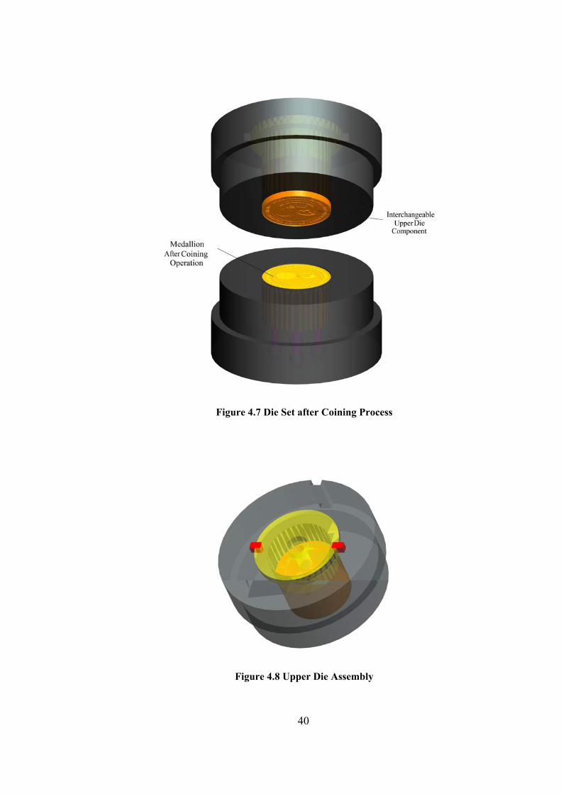
Figure 4.7 Die Set after Coining Process
Figure 4.8 Upper Die Assembly
40
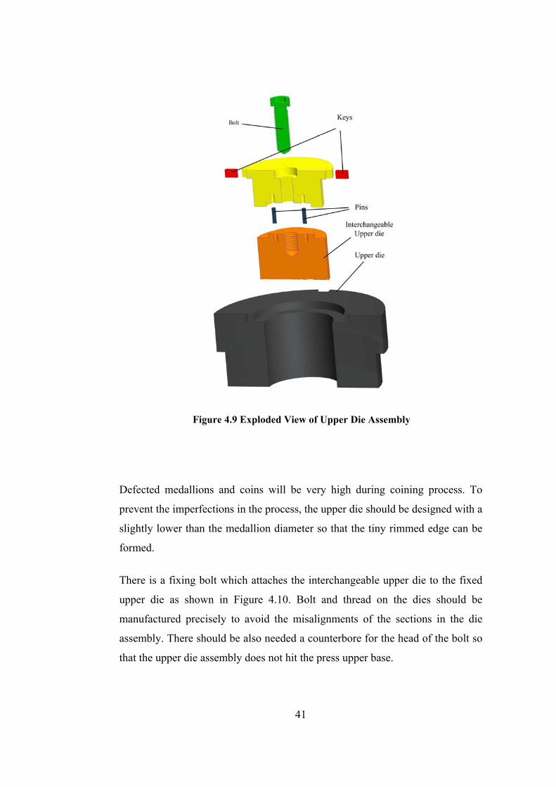
Figure 4.9 Exploded View of Upper Die Assembly
Defected medallions and coins will be very high during coining process. To
prevent the imperfections in the process, the upper die should be designed with a
slightly lower than the medallion diameter so that the tiny rimmed edge can be
formed.
There is a fixing bolt which attaches the interchangeable upper die to the fixed
upper die as shown in Figure 4.10. Bolt and thread on the dies should be
manufactured precisely to avoid the misalignments of the sections in the die
assembly. There should be also needed a counterbore for the head of the bolt so
that the upper die assembly does not hit the press upper base.
41
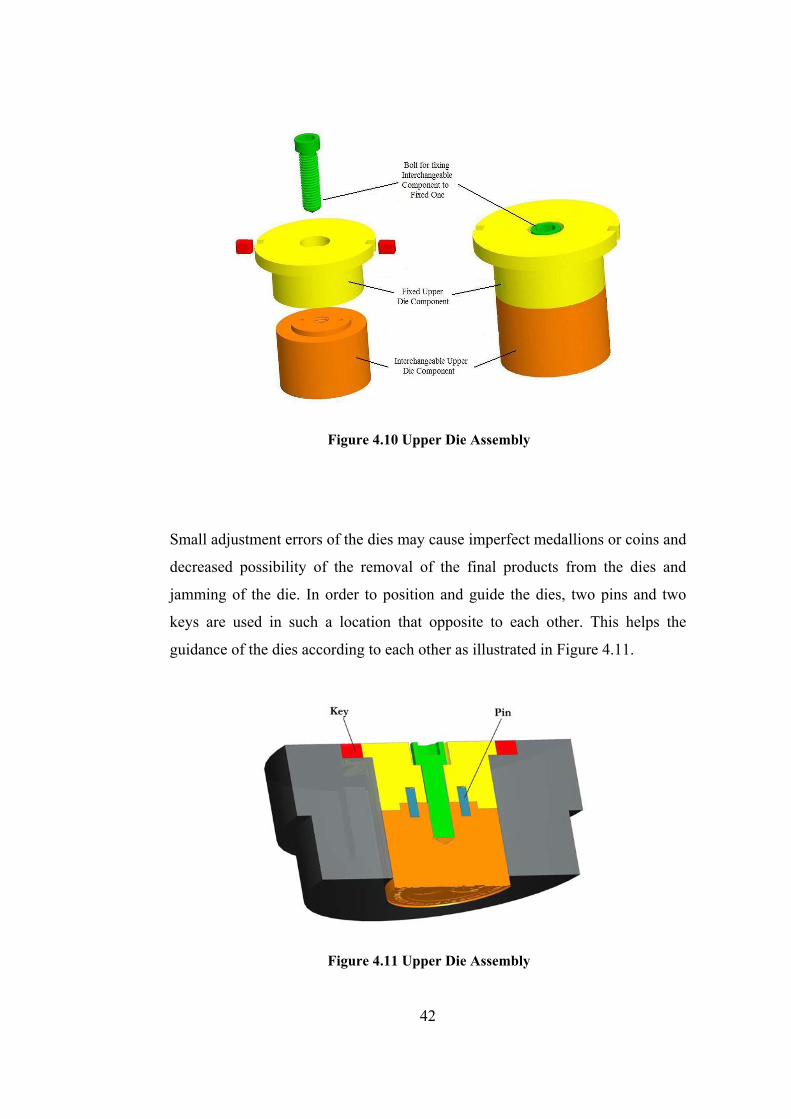
Figure 4.10 Upper Die Assembly
Small adjustment errors of the dies may cause imperfect medallions or coins and
decreased possibility of the removal of the final products from the dies and
jamming of the die. In order to position and guide the dies, two pins and two
keys are used in such a location that opposite to each other. This helps the
guidance of the dies according to each other as illustrated in Figure 4.11.
Figure 4.11 Upper Die Assembly
42
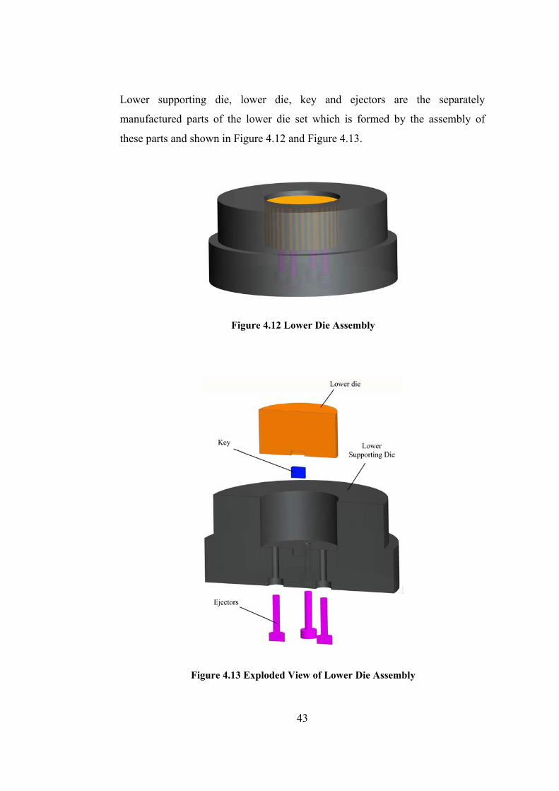
Lower supporting die, lower die, key and ejectors are the separately
manufactured parts of the lower die set which is formed by the assembly of
these parts and shown in Figure 4.12 and Figure 4.13.
Figure 4.12 Lower Die Assembly
Figure 4.13 Exploded View of Lower Die Assembly
43
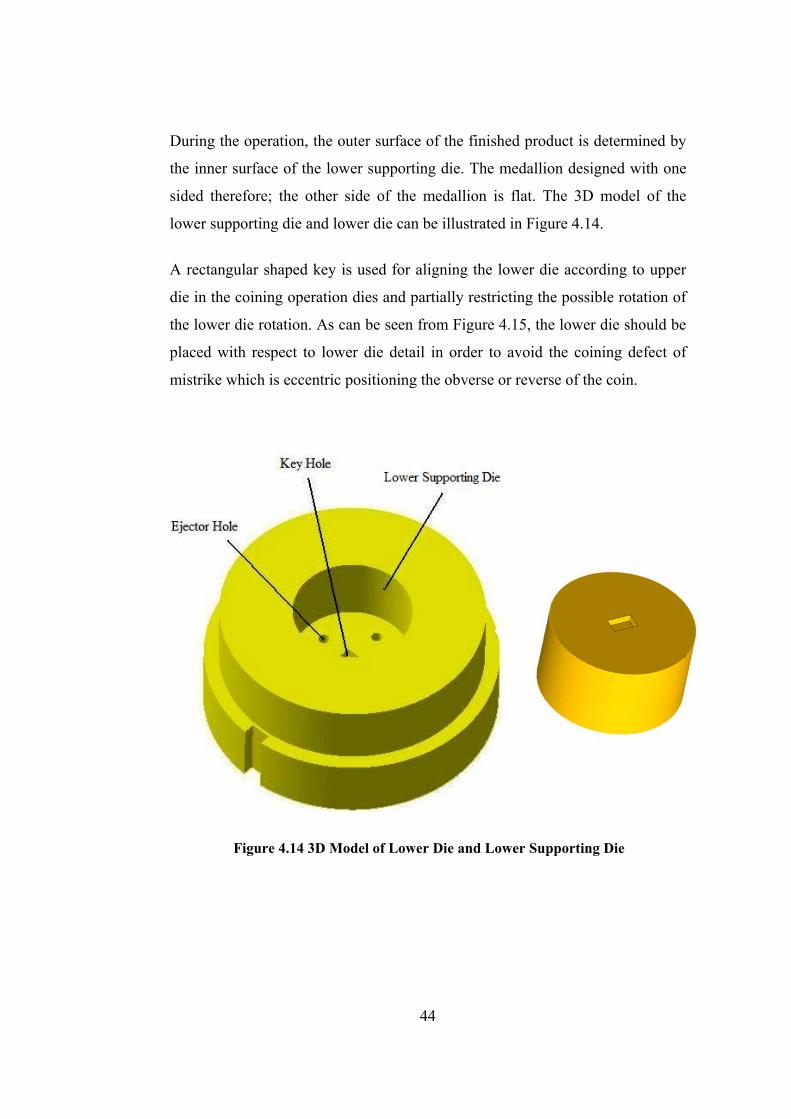
During the operation, the outer surface of the finished product is determined by
the inner surface of the lower supporting die. The medallion designed with one
sided therefore; the other side of the medallion is flat. The 3D model of the
lower supporting die and lower die can be illustrated in Figure 4.14.
A rectangular shaped key is used for aligning the lower die according to upper
die in the coining operation dies and partially restricting the possible rotation of
the lower die rotation. As can be seen from Figure 4.15, the lower die should be
placed with respect to lower die detail in order to avoid the coining defect of
mistrike which is eccentric positioning the obverse or reverse of the coin.
Figure 4.14 3D Model of Lower Die and Lower Supporting Die
44

Figure 4.15 Key Position of Lower Die Assembly
Removal of the medallion after the coinage process is made by ejector pins
moving the lower die upwards. Four ejectors pins that are placed through the
base section of the press are used and they provide equal force. The counterbore
of the lower supporting die for ejector heads were adjusted according to the
ejector length will easily remove the coined blank. The position of ejectors
removing the struck medallion can be shown in Figure 4.16.
Figure 4.16 Ejection of Medallion from the Lower Die Assembly
45

4.2 Design Modifications in Modular Die Set for Medallions with Different
Diameter Values
The ejectors on the particular forging press available in METU-BILTIR Center
Forging Research and Application Laboratory are on a pitch circle with a
diameter of 70 mm. This has affected the design.
As a result of the modularity of the coining die set, different decorative items on
the face or a different diameter of the medallion can be produced. For the
medallion with a diameter of 90 mm, the inner diameter of the lower supporting
die is equal to the outer diameter of the lower die.
However, for the diameters between 90 mm which is the inner diameter of the
lower supporting die and 70 mm which is the diameter of the pitch circle of
ejectors. As a result, an interchangeable ring should be used. This design can be
seen in Figure 4.17. Wall thickness of the stepped outer container will be equal
to the difference between the diameter of the medallion and 90 mm.
In this case, the outer diameter of the lower die is smaller than the diameter of
pitch circle of the ejector pins. For production of these medallions, a stepped
outer container which is placed between the lower supporting die and lower die
should be used to provide the completely closed die cavity. The design of die set
with an interchangeable stepped outer container can be seen in Figure 4.18.
Wall thickness of the stepped outer container will be equal to the difference
between the diameter of the medallion and 90 mm. The height of the stepped
section should be equal to the stroke of the ejectors so that ejectors are able to
remove the medallion. The geometric features of stepped outer diameter and
lower die can be seen in Figure 4.19.
46

Figure 4.17 Assembly of Die Set for Coin Diameter of 70 mm
Figure 4.18 Assembly of Die Set for Coin Diameter of 50 mm
47
CHAPTER 5
ANALYSIS AND MANUFACTURING OF THE COMMEMORATIVE
MEDALLION OF OPENING CEREMONY OF METU-BILTIR
FORGING RESEARCH AND APPLICATION LABORATORY
In the previous chapters, design and 3-D modeling of the coining and blanking
dies for a particular coining process were explained in detail. In this chapter,
design, analysis and manufacturing of the coining die set and the medallion of
the opening ceremony of METU-BILTIR Center Forging Research and
Application Laboratory will be explained. The finite volume analysis will also
be verified by experiments.
5.1 Design of the Medallion
In the design stage of the medallion, material of the dies, and available cutting
tools in METU-BILTIR Center CAD/CAM Research and Application
Laboratory were taken into account.
The outer diameter of the coin was chosen to be 90 mm. The thickness was set
as 5 mm and a relief height is set as 0.5 mm. The 3-D model of the medallion
can be seen in Figure.4.1.
After modeling the desired shape of the commemorative medallion and the dies
by using Pro/Engineer WF 3.0 [23], all of the manufacturing works of the dies
were accomplished in METU-BILTIR Center CAD/CAM Laboratory.
48
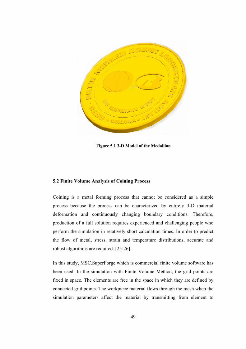
Figure 5.1 3-D Model of the Medallion
5.2 Finite Volume Analysis of Coining Process
Coining is a metal forming process that cannot be considered as a simple
process because the process can be characterized by entirely 3-D material
deformation and continuously changing boundary conditions. Therefore,
production of a full solution requires experienced and challenging people who
perform the simulation in relatively short calculation times. In order to predict
the flow of metal, stress, strain and temperature distributions, accurate and
robust algorithms are required. [25-26].
In this study, MSC.SuperForge which is commercial finite volume software has
been used. In the simulation with Finite Volume Method, the grid points are
fixed in space. The elements are free in the space in which they are defined by
connected grid points. The workpiece material flows through the mesh when the
simulation parameters affect the material by transmitting from element to
49
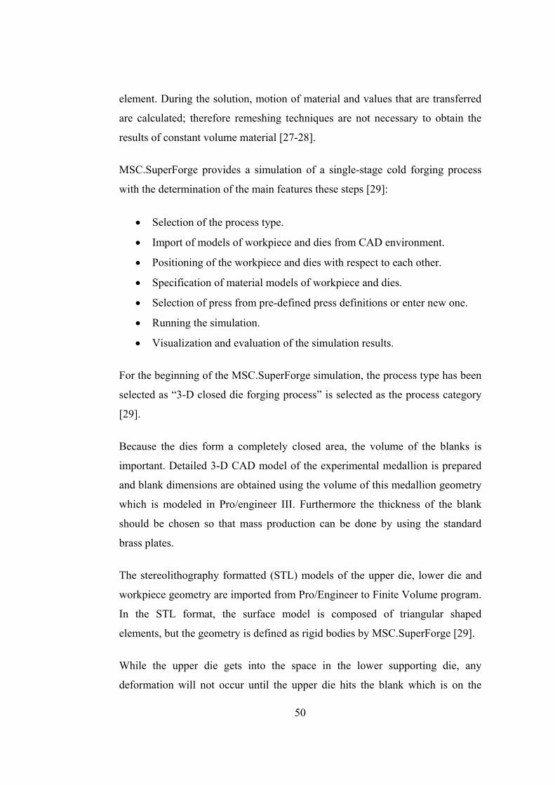
element. During the solution, motion of material and values that are transferred
are calculated; therefore remeshing techniques are not necessary to obtain the
results of constant volume material [27-28].
MSC.SuperForge provides a simulation of a single-stage cold forging process
with the determination of the main features these steps [29]:
• Selection of the process type.
• Import of models of workpiece and dies from CAD environment.
• Positioning of the workpiece and dies with respect to each other.
• Specification of material models of workpiece and dies.
• Selection of press from pre-defined press definitions or enter new one.
• Running the simulation.
• Visualization and evaluation of the simulation results.
For the beginning of the MSC.SuperForge simulation, the process type has been
selected as “3-D closed die forging process” is selected as the process category
[29].
Because the dies form a completely closed area, the volume of the blanks is
important. Detailed 3-D CAD model of the experimental medallion is prepared
and blank dimensions are obtained using the volume of this medallion geometry
which is modeled in Pro/engineer III. Furthermore the thickness of the blank
should be chosen so that mass production can be done by using the standard
brass plates.
The stereolithography formatted (STL) models of the upper die, lower die and
workpiece geometry are imported from Pro/Engineer to Finite Volume program.
In the STL format, the surface model is composed of triangular shaped
elements, but the geometry is defined as rigid bodies by MSC.SuperForge [29].
While the upper die gets into the space in the lower supporting die, any
deformation will not occur until the upper die hits the blank which is on the
50

lower die. Therefore the upper die and the lower die are simply modeled for the
simulation, as seen in Figure 5.1. The positions of the dies and the workpiece are
also shown in the figure.
Since the dies are considered to be rigid bodies in the simulation, only heat
conduction and heat transfer are allowed in the dies and it is not possible to
simulate strains and stresses on the dies. Therefore, the material is assigned for
the workpiece only. There is various material models already defined by in the
library, in the program. [29].
Figure 5.2 MSC.SuperForge Assembly for Coining Operation
From the available elastic-plastic models for cold forging in the material library,
“CuZn28/CuZn30” has been selected as the blank material. Material properties
of this metal have been presented as in Figure 5.3 [30].
51
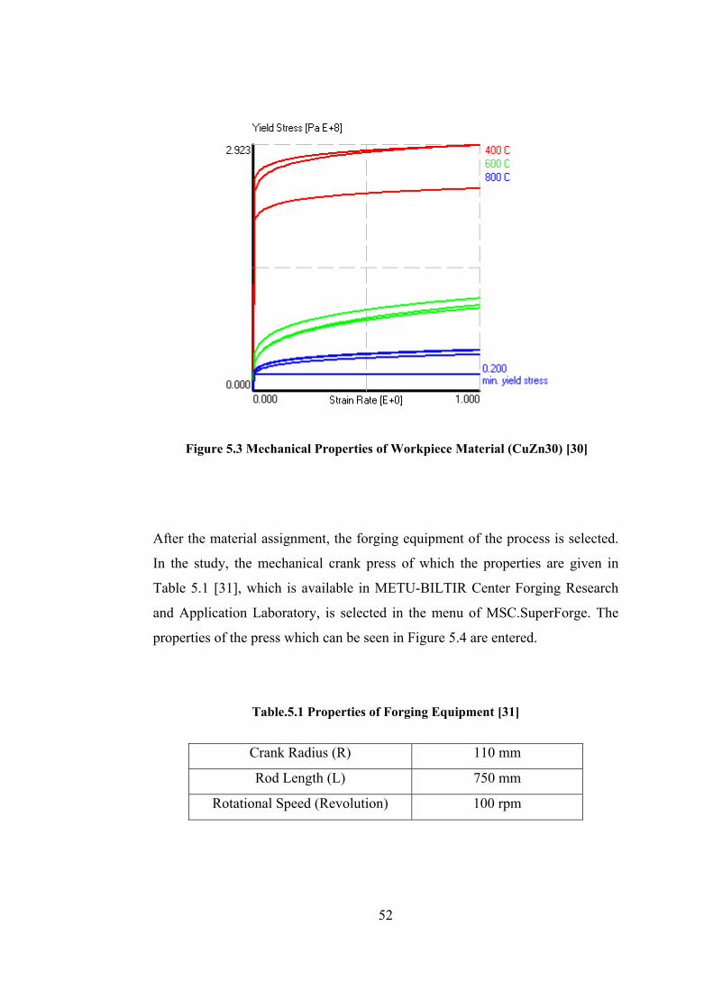
Figure 5.3 Mechanical Properties of Workpiece Material (CuZn30) [30]
After the material assignment, the forging equipment of the process is selected.
In the study, the mechanical crank press of which the properties are given in
Table 5.1 [31], which is available in METU-BILTIR Center Forging Research
and Application Laboratory, is selected in the menu of MSC.SuperForge. The
properties of the press which can be seen in Figure 5.4 are entered.
Table.5.1 Properties of Forging Equipment [31]
Crank Radius (R) 110 mm
Rod Length (L) 750 mm
Rotational Speed (Revolution) 100 rpm
52

Figure 5.4 Parameters for Mechanical Press in the Software [31]
By entering the given parameters, the velocity of the press can be obtained from
the software as a function of time as seen in Figure 5.5.
After implementing the press parameters, simulation conditions should be
determined as seen in Table 5.2 and these steps should be followed:
• Stroke of the upper die is selected.
• Size of the finite volume workpiece element is entered.
Output step size (as percentage of the process time or in defined stroke step
sizes) is incurred selectively.
53
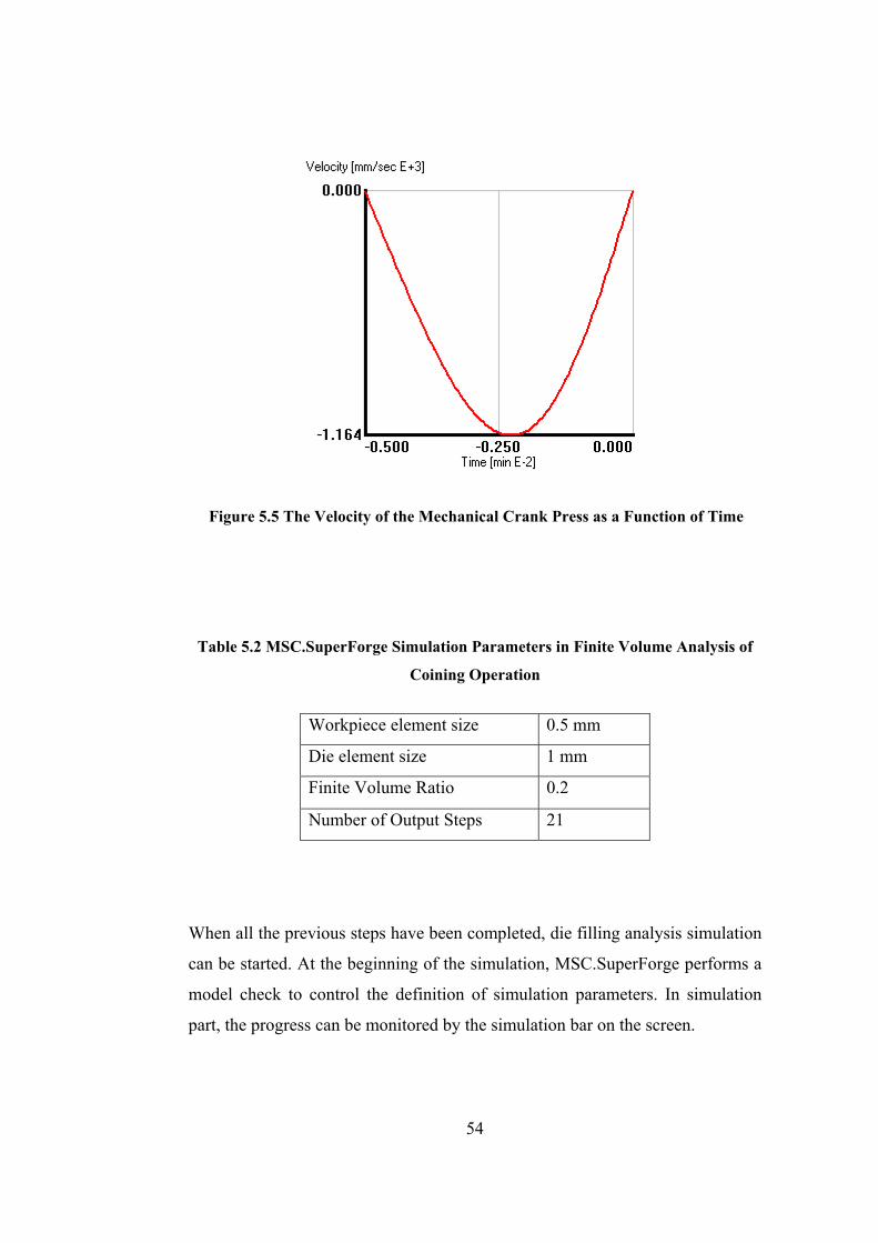
Figure 5.5 The Velocity of the Mechanical Crank Press as a Function of Time
Table 5.2 MSC.SuperForge Simulation Parameters in Finite Volume Analysis of
Coining Operation
Workpiece element size 0.5 mm
Die element size 1 mm
Finite Volume Ratio 0.2
Number of Output Steps 21
When all the previous steps have been completed, die filling analysis simulation
can be started. At the beginning of the simulation, MSC.SuperForge performs a
model check to control the definition of simulation parameters. In simulation
part, the progress can be monitored by the simulation bar on the screen.
54
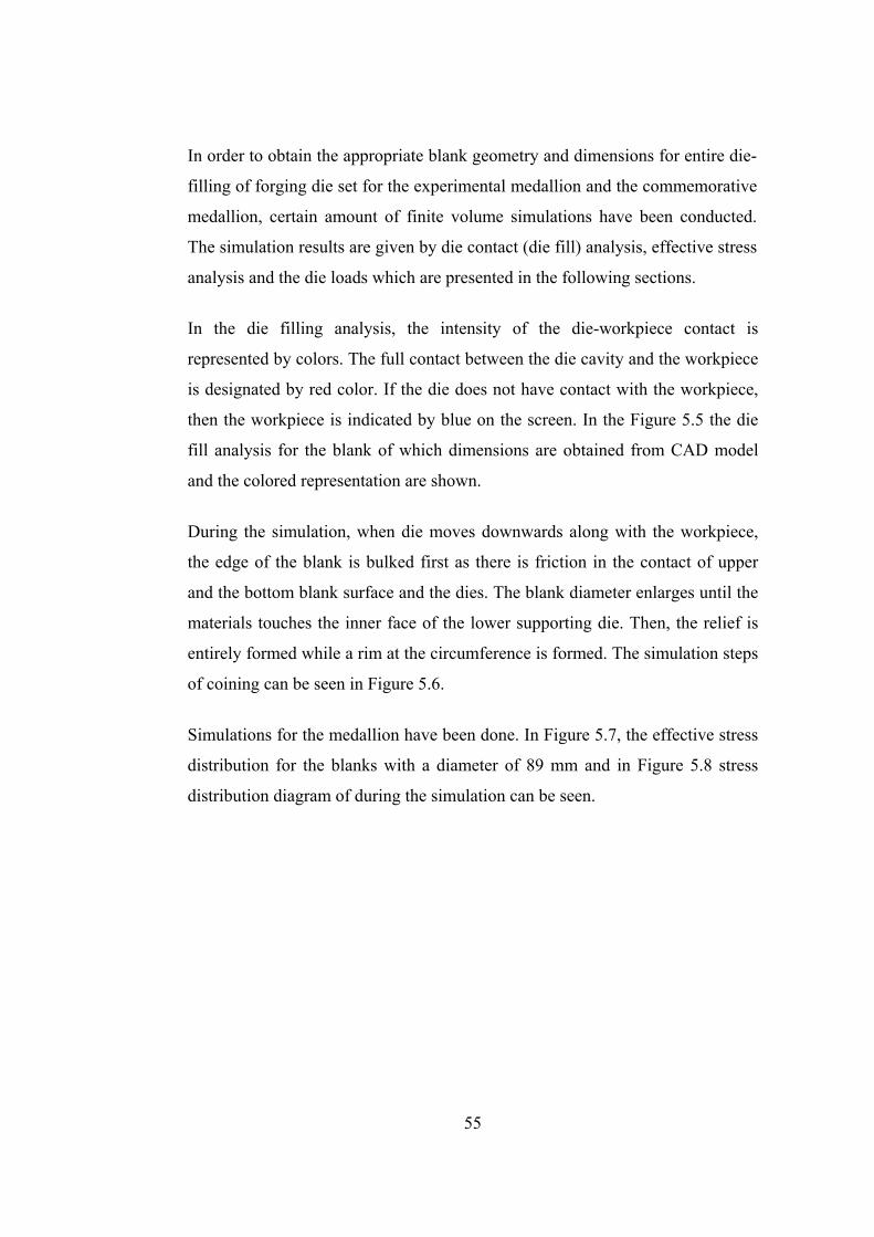
In order to obtain the appropriate blank geometry and dimensions for entire die-
filling of forging die set for the experimental medallion and the commemorative
medallion, certain amount of finite volume simulations have been conducted.
The simulation results are given by die contact (die fill) analysis, effective stress
analysis and the die loads which are presented in the following sections.
In the die filling analysis, the intensity of the die-workpiece contact is
represented by colors. The full contact between the die cavity and the workpiece
is designated by red color. If the die does not have contact with the workpiece,
then the workpiece is indicated by blue on the screen. In the Figure 5.5 the die
fill analysis for the blank of which dimensions are obtained from CAD model
and the colored representation are shown.
During the simulation, when die moves downwards along with the workpiece,
the edge of the blank is bulked first as there is friction in the contact of upper
and the bottom blank surface and the dies. The blank diameter enlarges until the
materials touches the inner face of the lower supporting die. Then, the relief is
entirely formed while a rim at the circumference is formed. The simulation steps
of coining can be seen in Figure 5.6.
Simulations for the medallion have been done. In Figure 5.7, the effective stress
distribution for the blanks with a diameter of 89 mm and in Figure 5.8 stress
distribution diagram of during the simulation can be seen.
55

Figure 5.6 Die Contact (Die Filling) Simulation Steps of the Coin
56

Figure 5.7 Effective Stress Distribution in the Blank with a Diameter of 89mm
Figure 5.8 Effective Plastic Strain Distribution in the Blank with a Diameter of 89
mm
57

5.3 Production of the Coining Die Sets
5.3.1 Dimensions of Die Holders on Press
Dimensional requirements of the available 1000 tones SMERAL mechanical
press [31] that can be seen in Figure 5.9 limit the dimensions and the geometry
of the die set.
Figure 5.9 A view of Smeral 1000-ton Mechanical Press in METU-BILTIR Center
Forging Research and Application Laboratory
The SMERAL 1000-ton mechanical press, of which the technical data is given
in Appendix C, has a ram stroke of 220 mm. The press has a shut height of 620
mm, which is the distance between the ram and the anvil when the ram is at its
bottom dead center as seen in Figure 5.10. When the die holder is placed, and
58
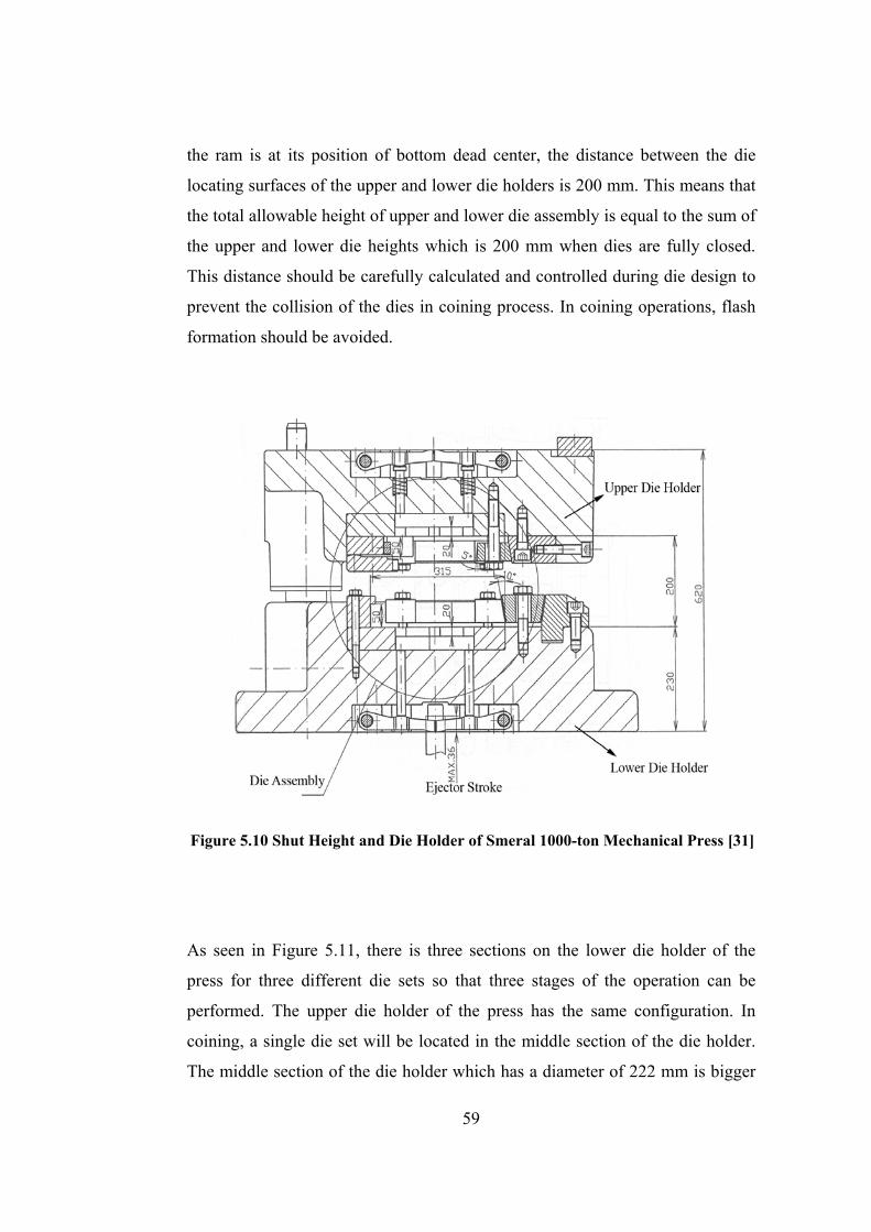
the ram is at its position of bottom dead center, the distance between the die
locating surfaces of the upper and lower die holders is 200 mm. This means that
the total allowable height of upper and lower die assembly is equal to the sum of
the upper and lower die heights which is 200 mm when dies are fully closed.
This distance should be carefully calculated and controlled during die design to
prevent the collision of the dies in coining process. In coining operations, flash
formation should be avoided.
Figure 5.10 Shut Height and Die Holder of Smeral 1000-ton Mechanical Press [31]
As seen in Figure 5.11, there is three sections on the lower die holder of the
press for three different die sets so that three stages of the operation can be
performed. The upper die holder of the press has the same configuration. In
coining, a single die set will be located in the middle section of the die holder.
The middle section of the die holder which has a diameter of 222 mm is bigger
59

than the sections at both sides which have a diameter of 197 mm. Technical
drawings and dimensions of the circular dies appropriate for the die holders are
given in Figure 5.12 and Figure 5.13. For each section of die holders, there is an
identically placed key seat in order dies to be alligned.
Surface of the die clamping elements mates the larger diameter of the die
holders when the clamping elements are fastened by bolts. This large die
surfaces that mate with the clamping elements are tapered at an angle of 5
degrees; the clamping elements also have the same angle. Additionally, the key
seats with a width of 16 mm have the tolerance of H8 [32]; and depth of 9 mm.
These features are designed in the dies to prevent the rotational motion of the
dies relative to the die holder.
Figure 5.11 A view of Lower Die Holder
60
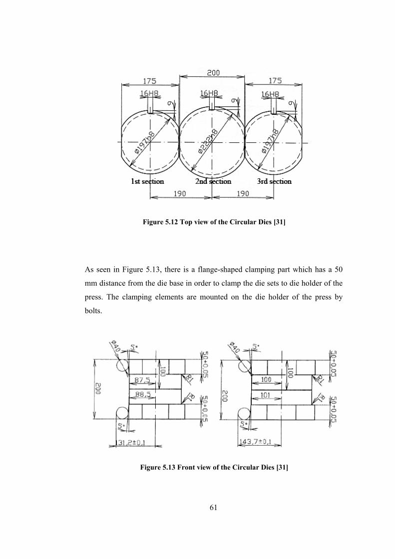
Figure 5.12 Top view of the Circular Dies [31]
As seen in Figure 5.13, there is a flange-shaped clamping part which has a 50
mm distance from the die base in order to clamp the die sets to die holder of the
press. The clamping elements are mounted on the die holder of the press by
bolts.
Figure 5.13 Front view of the Circular Dies [31]
61
5.3.2 Manufacturing of the Coining Dies
The design details of the medallion and die sets have been described in Chapter
4. After the dies are modeled in Pro/Engineer WF 3.0 and simulation of the
coining process is realized in MSC.SuperForge, NC codes to the die sets are
prepared using the manufacturing module of Pro/Engineer WF 3.0 [23]. During
the code generation, die cavity section for the letter is manufactured by using on
end mill with a diameter of 0.8 mm.
Sleipner is selected as the coining die material for interchangeable and fixed
upper die and lower die, due to its high hardness after high temperature
tempering, high compressive stress, high toughness at room temperature and its
good machinability [33]. For other parts, DIN 1.2714 [33] has been used,
because of its machinability and cheaper price. The detailed properties of
Sleipner and DIN 1.2714 [33] are given in Appendix A.
Manufacturing of the coining dies and blanking dies have been performed in
METU-BILTIR Center CAD/CAM Laboratory. After turning raw material to
the desired value of the diameter that is a little more than the exact size, the final
size of the dies are given in MAZAK Variaxis 630-5X high-speed vertical
milling machine, which is available in METU-BILTIR Center CAD/CAM
Laboratory.
The raw steel material is soft annealed so that the machining operations can be
easily done. After all the manufacturing operations are completed, the
interchangeable component of upper die is sent for heat treatment processes of
which details are given in Appendix B. as a result of the heat treatment, the
hardness of it will be 62 HRC. In Figures 5.14-5.23, the photographs and the
technical drawings of the dies can be seen.
62
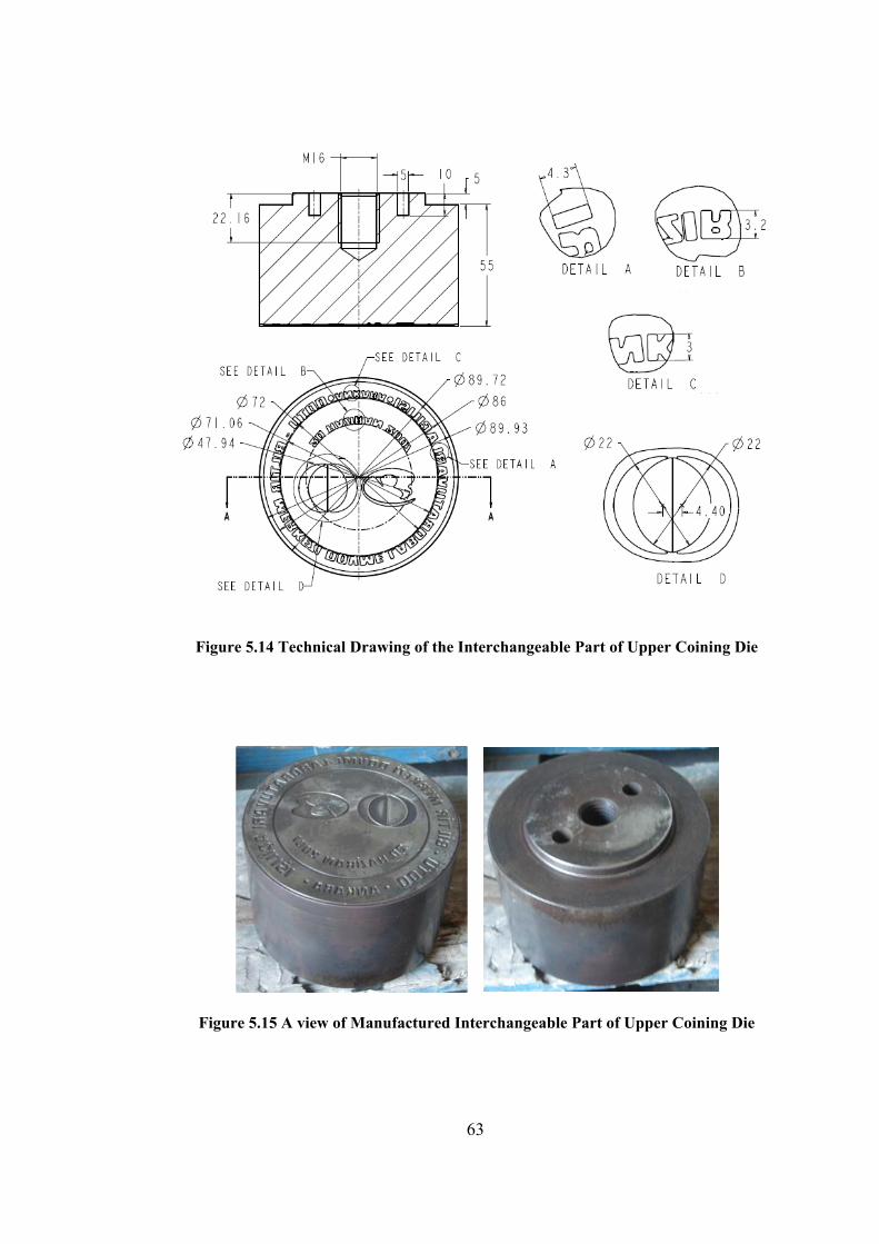
Figure 5.14 Technical Drawing of the Interchangeable Part of Upper Coining Die
Figure 5.15 A view of Manufactured Interchangeable Part of Upper Coining Die
63

Figure 5.16 Technical Drawing of the Upper Coining Supporting Die
Figure 5.17 A view of Manufactured Upper Coining Supporting Die
64
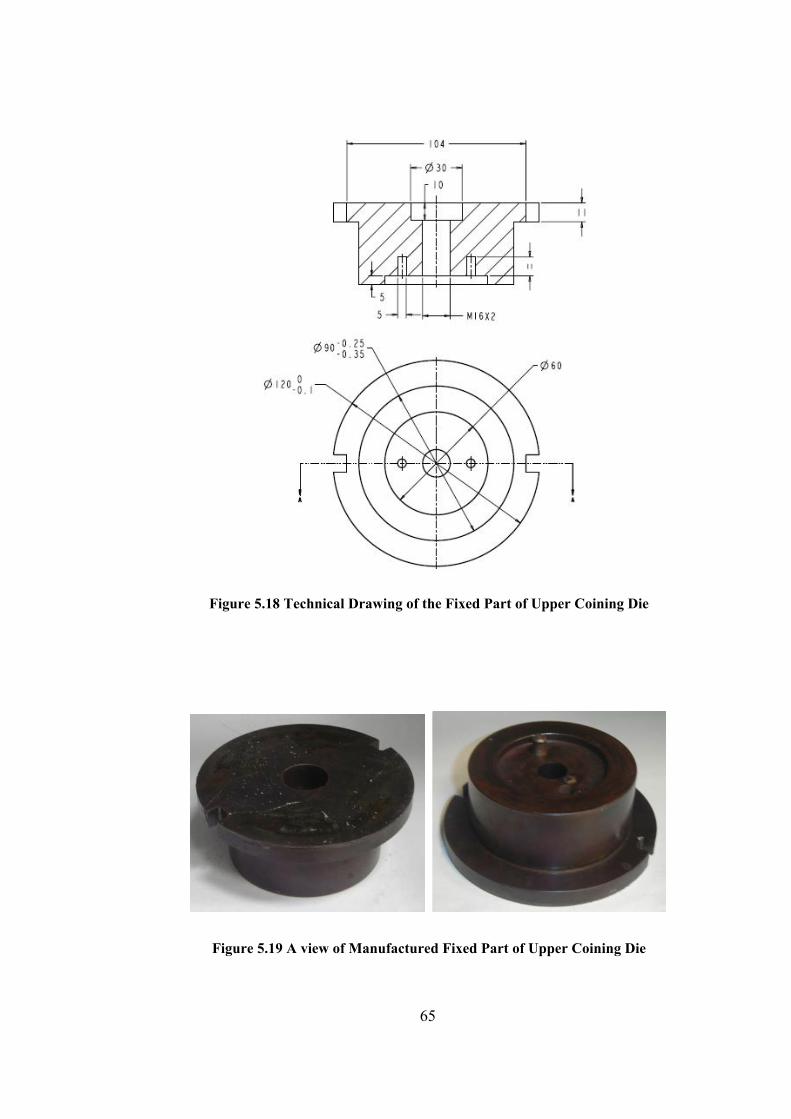
Figure 5.18 Technical Drawing of the Fixed Part of Upper Coining Die
Figure 5.19 A view of Manufactured Fixed Part of Upper Coining Die
65

Figure 5.20 Technical Drawing of the Lower Coining Die
Figure 5.21 A view of Manufactured Lower Die of Coining Die Set
66

Figure 5.22 Technical Drawing of the Lower Coining Supporting Die
Figure 5.23 A view of Manufactured Lower Coining Supporting Die
67
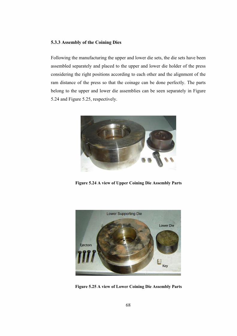
5.3.3 Assembly of the Coining Dies
Following the manufacturing the upper and lower die sets, the die sets have been
assembled separately and placed to the upper and lower die holder of the press
considering the right positions according to each other and the alignment of the
ram distance of the press so that the coinage can be done perfectly. The parts
belong to the upper and lower die assemblies can be seen separately in Figure
5.24 and Figure 5.25, respectively.
Figure 5.24 A view of Upper Coining Die Assembly Parts
Figure 5.25 A view of Lower Coining Die Assembly Parts
68
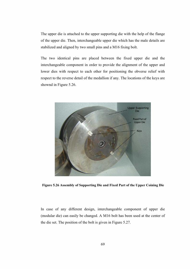
The upper die is attached to the upper supporting die with the help of the flange
of the upper die. Then, interchangeable upper die which has the male details are
stabilized and aligned by two small pins and a M16 fixing bolt.
The two identical pins are placed between the fixed upper die and the
interchangeable component in order to provide the alignment of the upper and
lower dies with respect to each other for positioning the obverse relief with
respect to the reverse detail of the medallion if any. The locations of the keys are
shownd in Figure 5.26.
Figure 5.26 Assembly of Supporting Die and Fixed Part of the Upper Coining Die
In case of any different design, interchangeable component of upper die
(modular die) can easily be changed. A M16 bolt has been used at the center of
the die set. The position of the bolt is given in Figure 5.27.
69
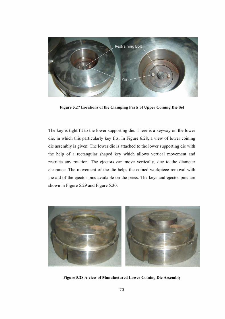
Figure 5.27 Locations of the Clamping Parts of Upper Coining Die Set
The key is tight fit to the lower supporting die. There is a keyway on the lower
die, in which this particularly key fits. In Figure 6.28, a view of lower coining
die assembly is given. The lower die is attached to the lower supporting die with
the help of a rectangular shaped key which allows vertical movement and
restricts any rotation. The ejectors can move vertically, due to the diameter
clearance. The movement of the die helps the coined workpiece removal with
the aid of the ejector pins available on the press. The keys and ejector pins are
shown in Figure 5.29 and Figure 5.30.
Figure 5.28 A view of Manufactured Lower Coining Die Assembly
70
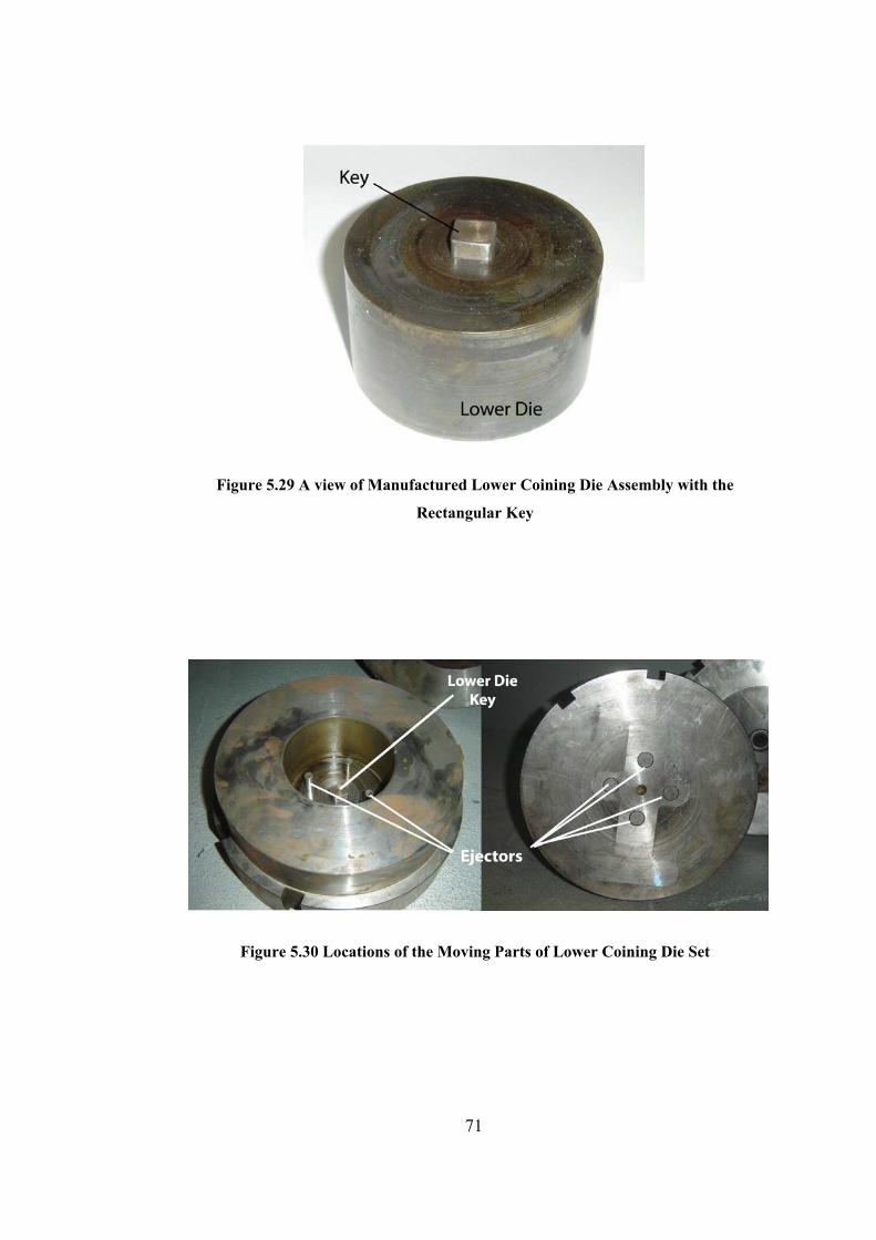
Figure 5.29 A view of Manufactured Lower Coining Die Assembly with the
Rectangular Key
Figure 5.30 Locations of the Moving Parts of Lower Coining Die Set
71
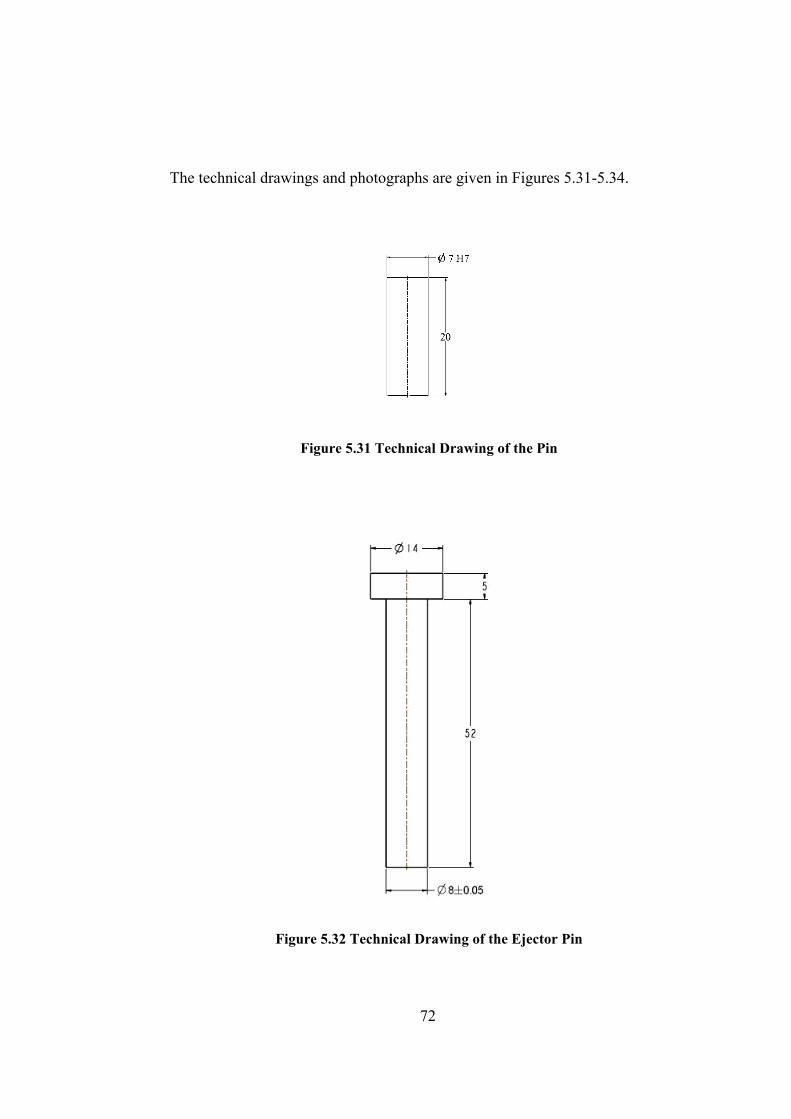
The technical drawings and photographs are given in Figures 5.31-5.34.
Figure 5.31 Technical Drawing of the Pin
Figure 5.32 Technical Drawing of the Ejector Pin
72
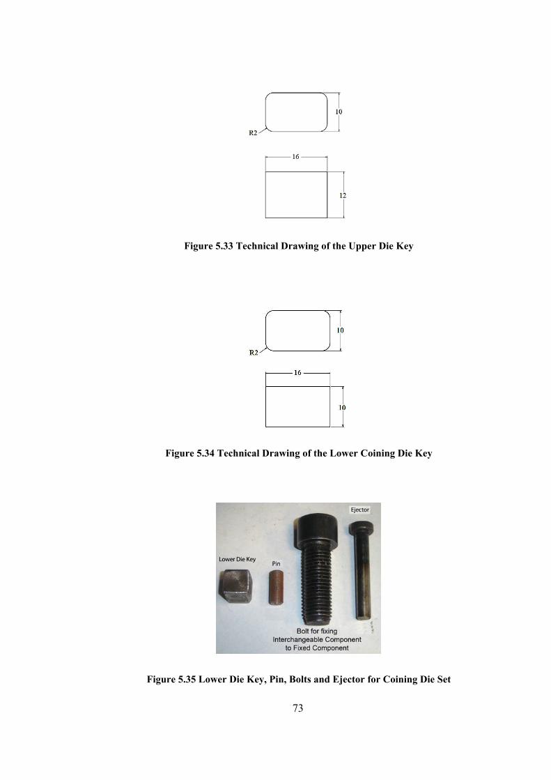
Figure 5.33 Technical Drawing of the Upper Die Key
Figure 5.34 Technical Drawing of the Lower Coining Die Key
Figure 5.35 Lower Die Key, Pin, Bolts and Ejector for Coining Die Set
73

During the set up of the upper die set, die assembly is lifted by using by a
hydraulic jack that is seated on a wedge above the lower supporting die. Then,
the supporting die attached to the upper die holder of the press using die
clamping elements. After ensuring that clamping elements are placed
adequately, die set is fastened with bolts for each clamping elements. Then, the
lower supporting die is placed on the lower die holder of the press inserting the
keys into the key seats on the lower die holder. Keys prevent rotational motion
of the die sets and by this way prevent defect of coinage. The lower supporting
die is fixed to the lower die holder using clamping elements and bolts. The
mounted die sets can be seen in Figure 5.36.
Figure 5.36 A view of Mounted Coining Dies on the Press
After both of the upper and lower dies are mounted, alignment of them is
checked with few test shots when the press is in unloaded position. After it is
ensured that the alignment of the upper and lower dies is done appropriately, the
74

upper die set is brought to the upper dead center so that shut height can be
adjusted for the coining process.
In Figure 5.37, upper die set assembly can be seen. a view of mounted dies can
be also seen in Figure 5.38.
Figure 5.37 A view of Assembled Upper Die Set
Figure 5.38 A view of Die Sets before the Coinage
75
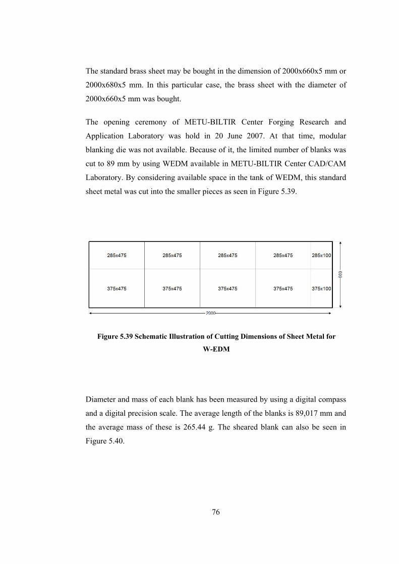
The standard brass sheet may be bought in the dimension of 2000x660x5 mm or
2000x680x5 mm. In this particular case, the brass sheet with the diameter of
2000x660x5 mm was bought.
The opening ceremony of METU-BILTIR Center Forging Research and
Application Laboratory was hold in 20 June 2007. At that time, modular
blanking die was not available. Because of it, the limited number of blanks was
cut to 89 mm by using WEDM available in METU-BILTIR Center CAD/CAM
Laboratory. By considering available space in the tank of WEDM, this standard
sheet metal was cut into the smaller pieces as seen in Figure 5.39.
Figure 5.39 Schematic Illustration of Cutting Dimensions of Sheet Metal for
W-EDM
Diameter and mass of each blank has been measured by using a digital compass
and a digital precision scale. The average length of the blanks is 89,017 mm and
the average mass of these is 265.44 g. The sheared blank can also be seen in
Figure 5.40.
76

Figure 5.40 Circular Blanks Manufactured with W-EDM
5.4.2 Real Life Experiments for Coining of Commemorative Medallion
The blank is located into the lower supporting die as seen in Figure 5.41. The
manufactured medallion on the die after the coining operation can be seen in
Figure 5.42.
Figure 5.41 A view of the Blank on the Lower Supporting Die
77
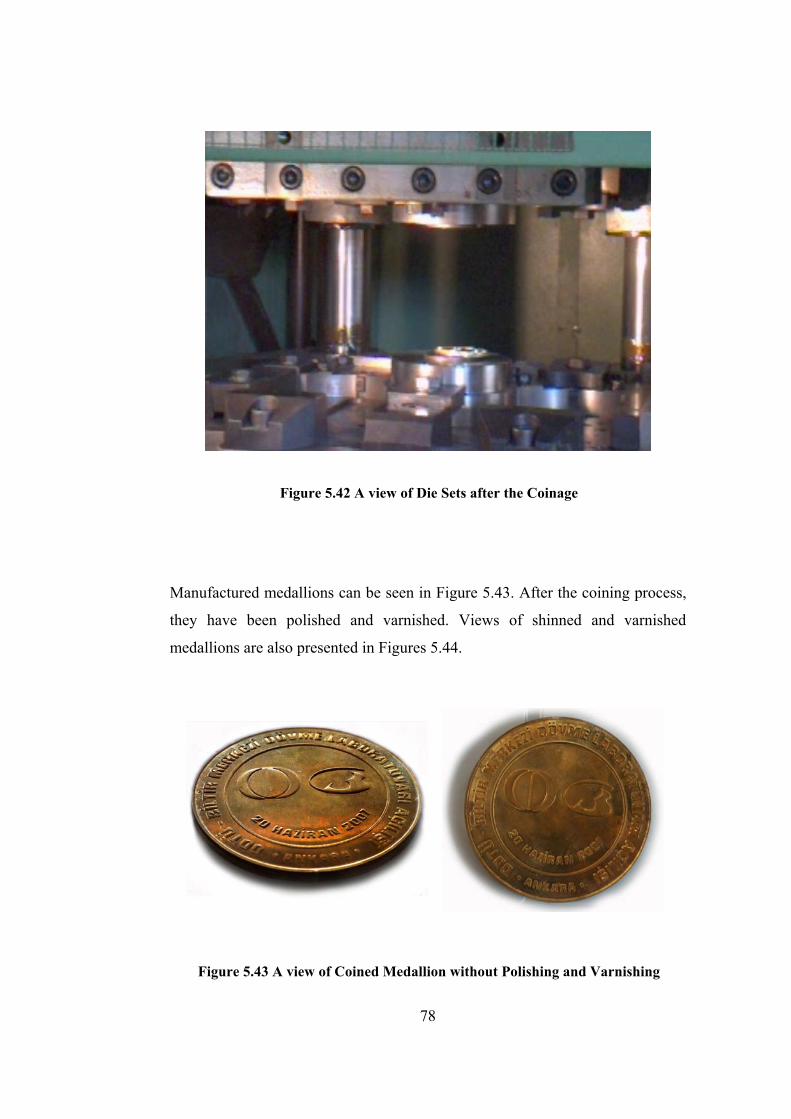
Figure 5.42 A view of Die Sets after the Coinage
Manufactured medallions can be seen in Figure 5.43. After the coining process,
they have been polished and varnished. Views of shinned and varnished
medallions are also presented in Figures 5.44.
Figure 5.43 A view of Coined Medallion without Polishing and Varnishing
78
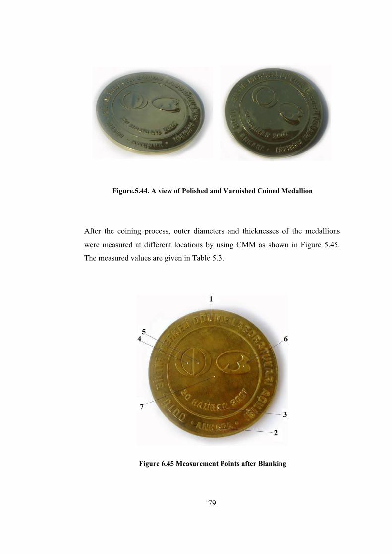
Figure.5.44. A view of Polished and Varnished Coined Medallion
After the coining process, outer diameters and thicknesses of the medallions
were measured at different locations by using CMM as shown in Figure 5.45.
The measured values are given in Table 5.3.
Figure 6.45 Measurement Points after Blanking
79
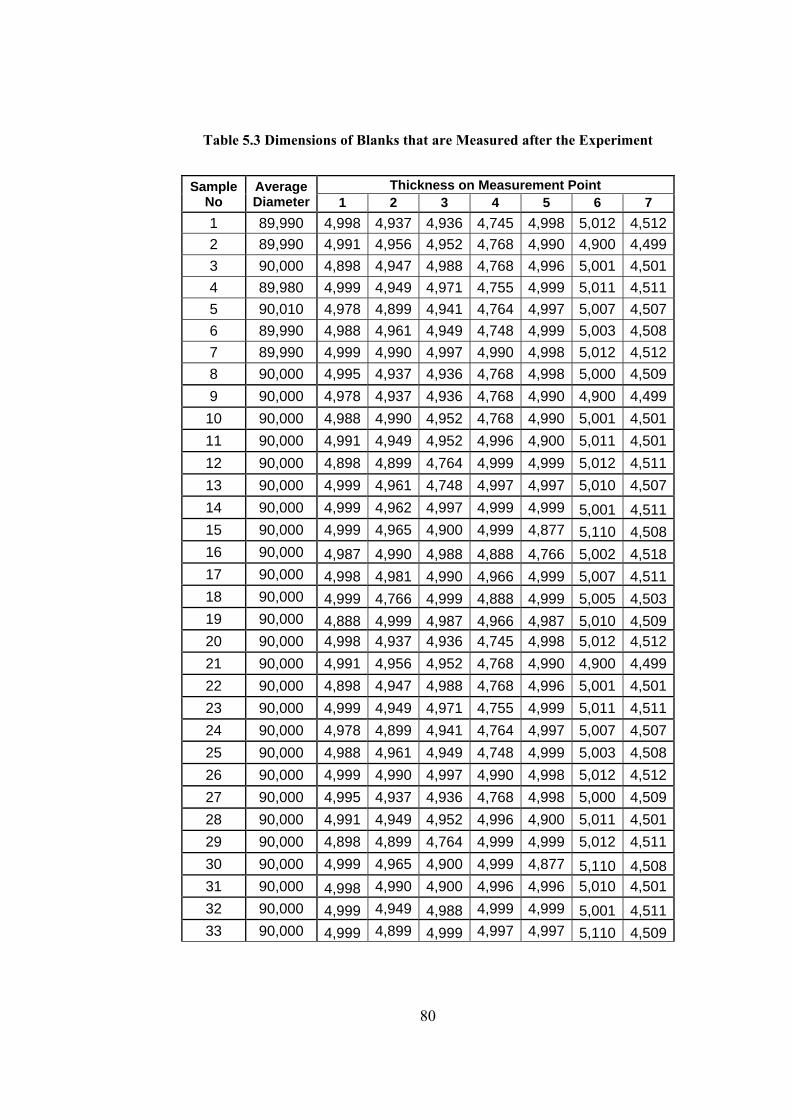
Table 5.3 Dimensions of Blanks that are Measured after the Experiment
Sample No
Average Diameter
Thickness on Measurement Point 1 2 3 4 5 6 7
1 89,990 4,998 4,937 4,936 4,745 4,998 5,012 4,5122 89,990 4,991 4,956 4,952 4,768 4,990 4,900 4,4993 90,000 4,898 4,947 4,988 4,768 4,996 5,001 4,5014 89,980 4,999 4,949 4,971 4,755 4,999 5,011 4,5115 90,010 4,978 4,899 4,941 4,764 4,997 5,007 4,5076 89,990 4,988 4,961 4,949 4,748 4,999 5,003 4,5087 89,990 4,999 4,990 4,997 4,990 4,998 5,012 4,5128 90,000 4,995 4,937 4,936 4,768 4,998 5,000 4,5099 90,000 4,978 4,937 4,936 4,768 4,990 4,900 4,499
10 90,000 4,988 4,990 4,952 4,768 4,990 5,001 4,50111 90,000 4,991 4,949 4,952 4,996 4,900 5,011 4,50112 90,000 4,898 4,899 4,764 4,999 4,999 5,012 4,51113 90,000 4,999 4,961 4,748 4,997 4,997 5,010 4,50714 90,000 4,999 4,962 4,997 4,999 4,999 5,001 4,51115 90,000 4,999 4,965 4,900 4,999 4,877 5,110 4,50816 90,000 4,987 4,990 4,988 4,888 4,766 5,002 4,51817 90,000 4,998 4,981 4,990 4,966 4,999 5,007 4,51118 90,000 4,999 4,766 4,999 4,888 4,999 5,005 4,50319 90,000 4,888 4,999 4,987 4,966 4,987 5,010 4,50920 90,000 4,998 4,937 4,936 4,745 4,998 5,012 4,51221 90,000 4,991 4,956 4,952 4,768 4,990 4,900 4,49922 90,000 4,898 4,947 4,988 4,768 4,996 5,001 4,50123 90,000 4,999 4,949 4,971 4,755 4,999 5,011 4,51124 90,000 4,978 4,899 4,941 4,764 4,997 5,007 4,50725 90,000 4,988 4,961 4,949 4,748 4,999 5,003 4,50826 90,000 4,999 4,990 4,997 4,990 4,998 5,012 4,51227 90,000 4,995 4,937 4,936 4,768 4,998 5,000 4,50928 90,000 4,991 4,949 4,952 4,996 4,900 5,011 4,50129 90,000 4,898 4,899 4,764 4,999 4,999 5,012 4,51130 90,000 4,999 4,965 4,900 4,999 4,877 5,110 4,50831 90,000 4,998 4,990 4,900 4,996 4,996 5,010 4,50132 90,000 4,999 4,949 4,988 4,999 4,999 5,001 4,51133 90,000 4,999 4,899 4,999 4,997 4,997 5,110 4,509
80
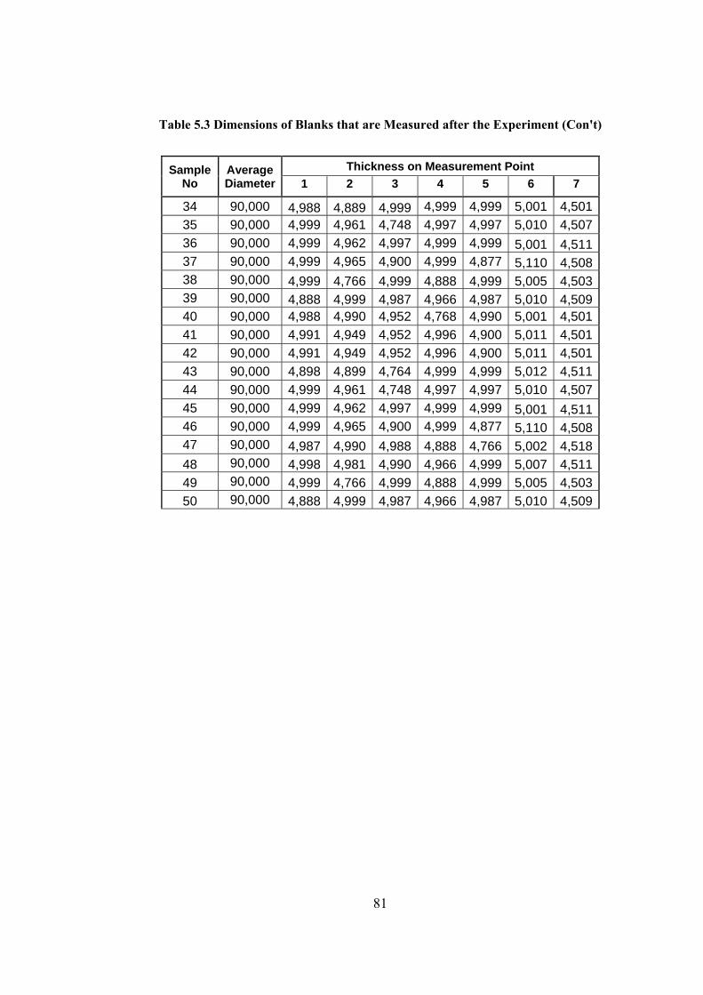
Table 5.3 Dimensions of Blanks that are Measured after the Experiment (Con't)
Sample No
Average Diameter
Thickness on Measurement Point 1 2 3 4 5 6 7
34 90,000 4,988 4,889 4,999 4,999 4,999 5,001 4,50135 90,000 4,999 4,961 4,748 4,997 4,997 5,010 4,50736 90,000 4,999 4,962 4,997 4,999 4,999 5,001 4,51137 90,000 4,999 4,965 4,900 4,999 4,877 5,110 4,50838 90,000 4,999 4,766 4,999 4,888 4,999 5,005 4,50339 90,000 4,888 4,999 4,987 4,966 4,987 5,010 4,50940 90,000 4,988 4,990 4,952 4,768 4,990 5,001 4,50141 90,000 4,991 4,949 4,952 4,996 4,900 5,011 4,50142 90,000 4,991 4,949 4,952 4,996 4,900 5,011 4,50143 90,000 4,898 4,899 4,764 4,999 4,999 5,012 4,51144 90,000 4,999 4,961 4,748 4,997 4,997 5,010 4,50745 90,000 4,999 4,962 4,997 4,999 4,999 5,001 4,51146 90,000 4,999 4,965 4,900 4,999 4,877 5,110 4,50847 90,000 4,987 4,990 4,988 4,888 4,766 5,002 4,51848 90,000 4,998 4,981 4,990 4,966 4,999 5,007 4,51149 90,000 4,999 4,766 4,999 4,888 4,999 5,005 4,50350 90,000 4,888 4,999 4,987 4,966 4,987 5,010 4,509
81
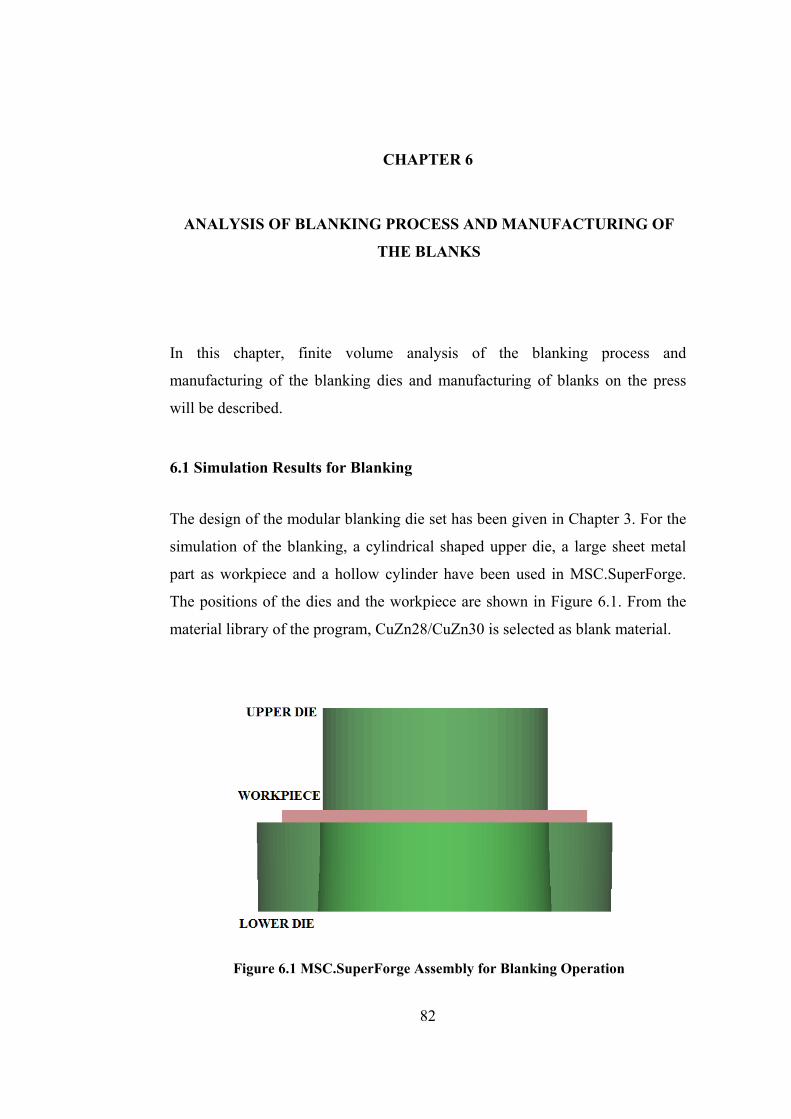
CHAPTER 6
ANALYSIS OF BLANKING PROCESS AND MANUFACTURING OF
THE BLANKS
In this chapter, finite volume analysis of the blanking process and
manufacturing of the blanking dies and manufacturing of blanks on the press
will be described.
6.1 Simulation Results for Blanking
The design of the modular blanking die set has been given in Chapter 3. For the
simulation of the blanking, a cylindrical shaped upper die, a large sheet metal
part as workpiece and a hollow cylinder have been used in MSC.SuperForge.
The positions of the dies and the workpiece are shown in Figure 6.1. From the
material library of the program, CuZn28/CuZn30 is selected as blank material.
Figure 6.1 MSC.SuperForge Assembly for Blanking Operation
82

In the study, Dirinler 200-ton press which is available in METU-BILTIR Center
Forging Research and Application Laboratory is used. the properties of the press
is given in Appendix D.
As the result of the finite volume simulation of blanking, the effective stress
distributions are illustrated in In Figure 6.2 and Figure 6.3; the effective plastic
strain distribution for the blanks is also given in Figure 6.4.
Figure 6.2 Effective Stress Distribution for Blanks
Figure 6.3 Cross Section of Effective Stress Distribution for Blanks
83
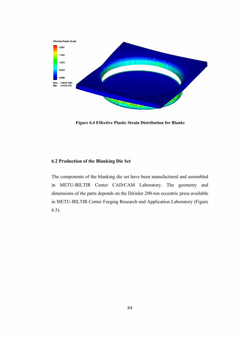
Figure 6.4 Effective Plastic Strain Distribution for Blanks
6.2 Production of the Blanking Die Set
The components of the blanking die set have been manufactured and assembled
in METU-BILTIR Center CAD/CAM Laboratory. The geometry and
dimensions of the parts depends on the Dirinler 200-ton eccentric press available
in METU-BILTIR Center Forging Research and Application Laboratory (Figure
6.5).
84
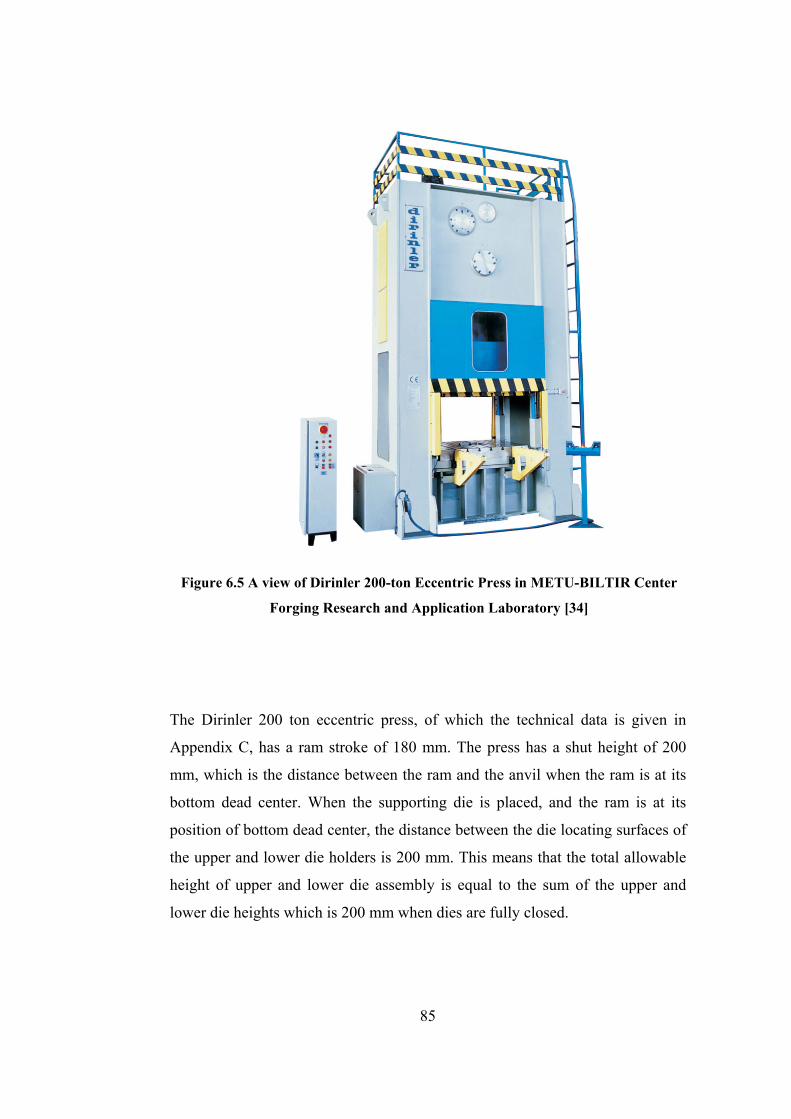
Figure 6.5 A view of Dirinler 200-ton Eccentric Press in METU-BILTIR Center
Forging Research and Application Laboratory [34]
The Dirinler 200 ton eccentric press, of which the technical data is given in
Appendix C, has a ram stroke of 180 mm. The press has a shut height of 200
mm, which is the distance between the ram and the anvil when the ram is at its
bottom dead center. When the supporting die is placed, and the ram is at its
position of bottom dead center, the distance between the die locating surfaces of
the upper and lower die holders is 200 mm. This means that the total allowable
height of upper and lower die assembly is equal to the sum of the upper and
lower die heights which is 200 mm when dies are fully closed.
85

The design details of the die set are given in Chapter 3. After the dies are
modeled in Pro/Engineer WF 3.0 and simulation of the blanking process in
MSC.SuperForge, NC codes of the die sets are prepared using the
manufacturing module of Pro/Engineer WF 3.0.
Sleipner, because of its high hardness after high temperature tempering, high
compressive stress, high toughness at room temperatures and its good
machinability is used, for the upper die only. DIN 1.1730, because of its
machinability and cheaper price is selected for the rest of the components. The
detailed properties of Sleipner and DIN 1.1730 [33] are given in Appendix A.
Manufacturing of the blanking dies has been performed in METU-BILTIR
Center CAD/CAM Laboratory. After turning raw material to the desired
diameter value which is slightly more than the exact size, the final size of the
dies are given in MAZAK Variaxis 630-5X high-speed vertical milling machine,
which is available in METU-BILTIR Center CAD/CAM Laboratory.
The die sets are fastened to the die holders on the press by using T-slots on the
die holders. In Figures 6.6- 6.19, the technical drawings of the die set and the
manufactured components can be seen.
86
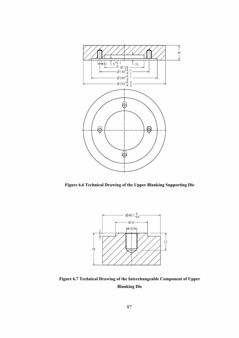
Figure 6.6 Technical Drawing of the Upper Blanking Supporting Die
Figure 6.7 Technical Drawing of the Interchangeable Component of Upper
Blanking Die
87
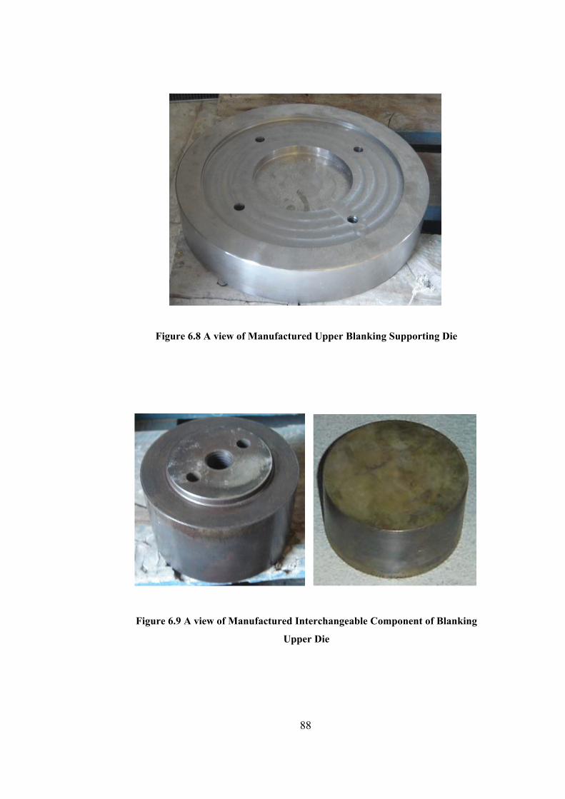
Figure 6.8 A view of Manufactured Upper Blanking Supporting Die
Figure 6.9 A view of Manufactured Interchangeable Component of Blanking
Upper Die
88
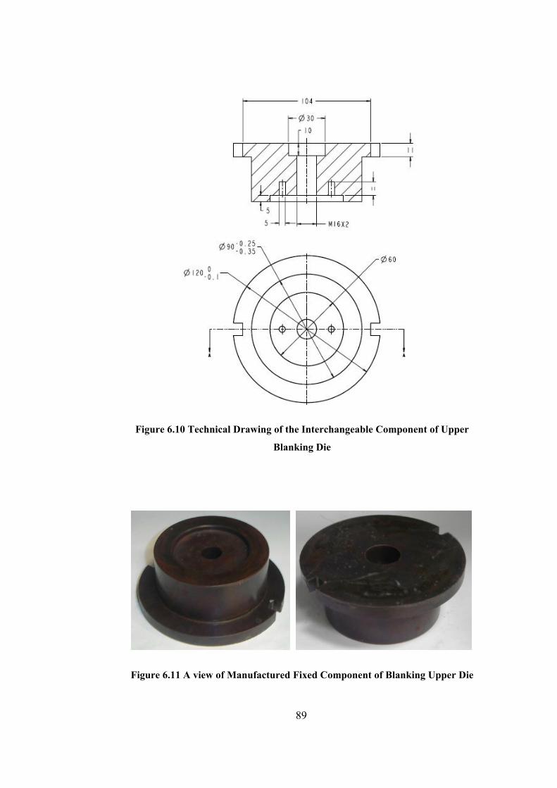
Figure 6.10 Technical Drawing of the Interchangeable Component of Upper
Blanking Die
Figure 6.11 A view of Manufactured Fixed Component of Blanking Upper Die
89
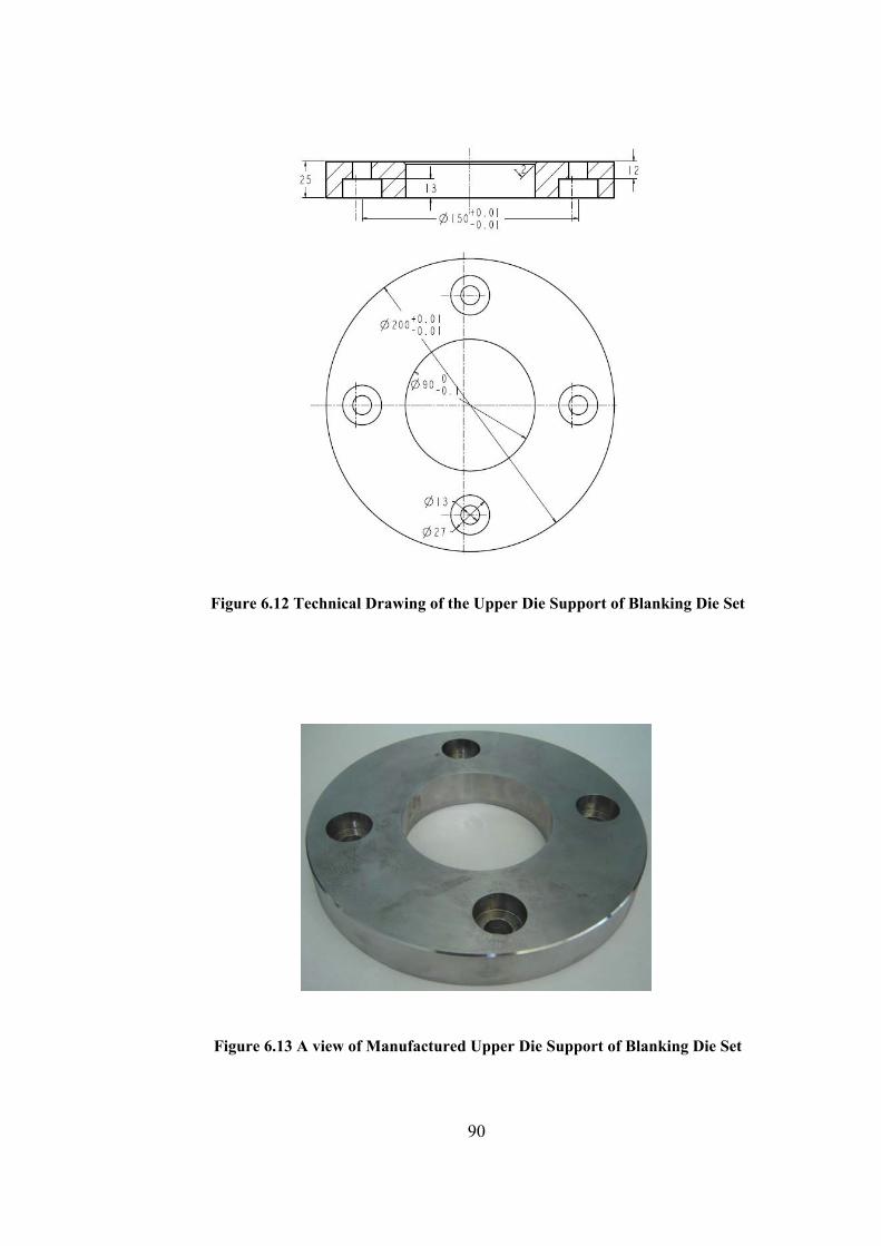
Figure 6.12 Technical Drawing of the Upper Die Support of Blanking Die Set
Figure 6.13 A view of Manufactured Upper Die Support of Blanking Die Set
90
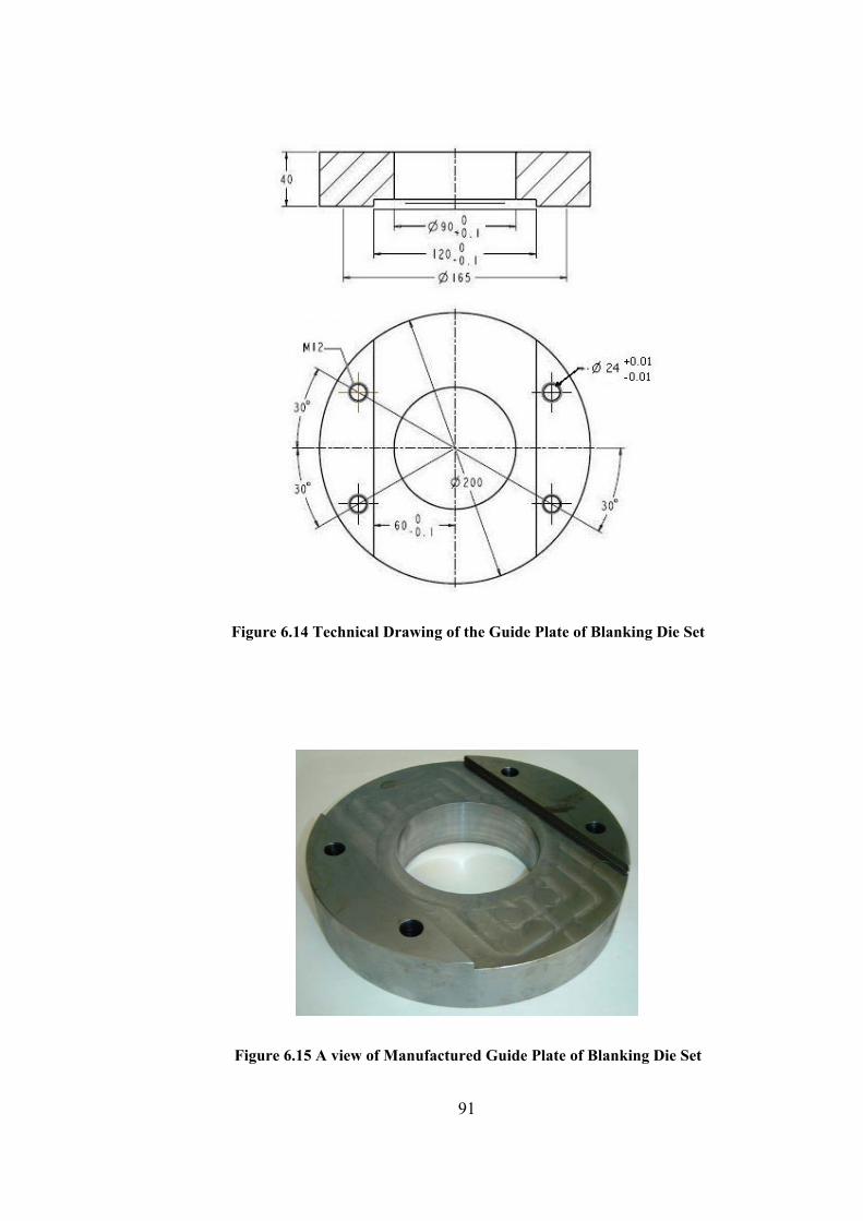
Figure 6.14 Technical Drawing of the Guide Plate of Blanking Die Set
Figure 6.15 A view of Manufactured Guide Plate of Blanking Die Set
91
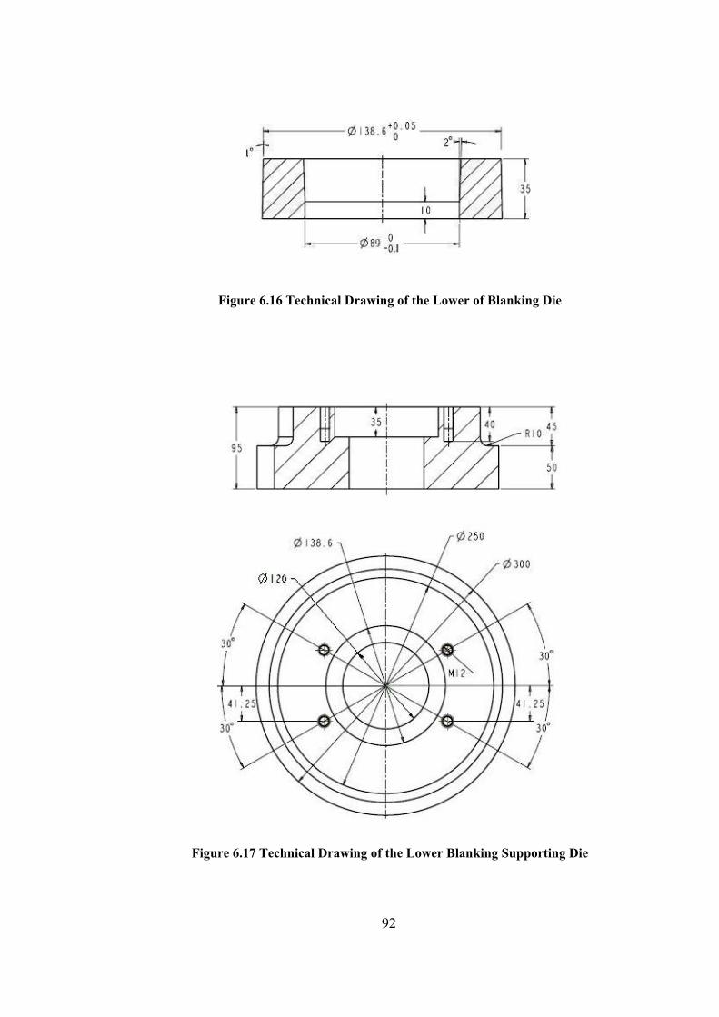
Figure 6.16 Technical Drawing of the Lower of Blanking Die
Figure 6.17 Technical Drawing of the Lower Blanking Supporting Die
92
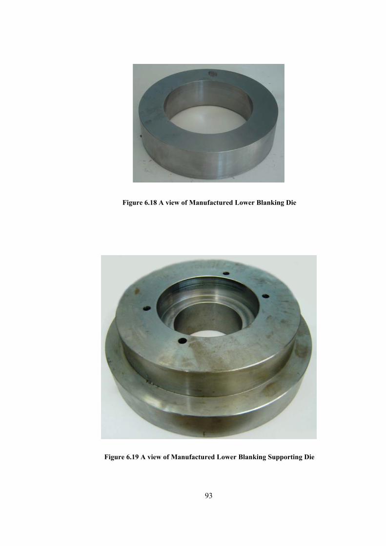
Figure 6.18 A view of Manufactured Lower Blanking Die
Figure 6.19 A view of Manufactured Lower Blanking Supporting Die
93
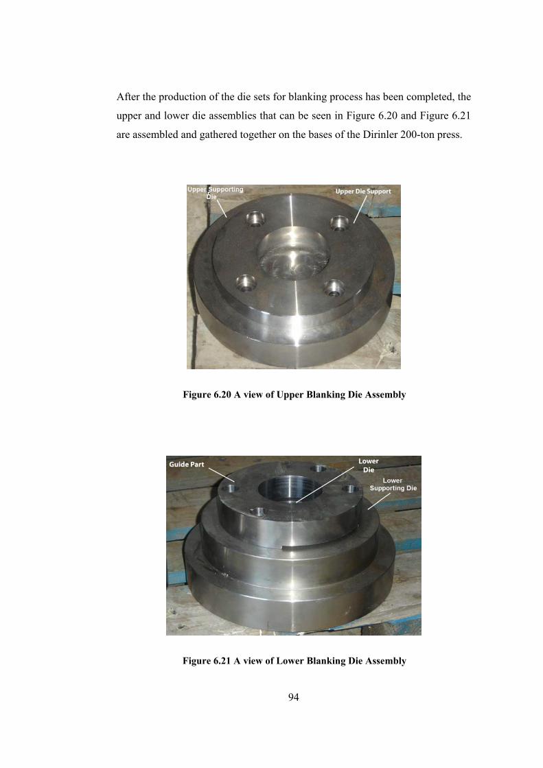
After the production of the die sets for blanking process has been completed, the
upper and lower die assemblies that can be seen in Figure 6.20 and Figure 6.21
are assembled and gathered together on the bases of the Dirinler 200-ton press.
Figure 6.20 A view of Upper Blanking Die Assembly
Figure 6.21 A view of Lower Blanking Die Assembly
94
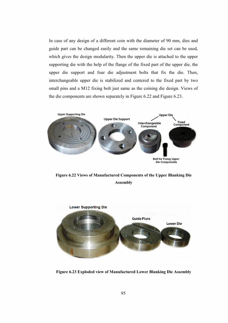
In case of any design of a different coin with the diameter of 90 mm, dies and
guide part can be changed easily and the same remaining die set can be used,
which gives the design modularity. Then the upper die is attached to the upper
supporting die with the help of the flange of the fixed part of the upper die, the
upper die support and four die adjustment bolts that fix the die. Then,
interchangeable upper die is stabilized and centered to the fixed part by two
small pins and a M12 fixing bolt just same as the coining die design. Views of
the die components are shown separately in Figure 6.22 and Figure 6.23.
Figure 6.22 Views of Manufactured Components of the Upper Blanking Die
Assembly
Figure 6.23 Exploded view of Manufactured Lower Blanking Die Assembly
95

During the set up of the upper die set, die assembly is seated onto the base
considering the position of the lower supporting die. Then, the supporting die
attached to the upper die holder of the press using die clamping elements. After
ensuring that clamping elements are placed adequately, die set is fastened with
bolts for each clamping elements. Lower die should be centered correctly to
prevent the possible damage of dies or inaccurate blank production due to the
eccentrically applied shear force. The guide part, finally, placed by the help of
four bolts to support the sheet metal and prevent the damage of the strip during
blanking. Fixing bolt and die adjustment bolts can be shown in Figure 6.24 and
the whole assembly picture of the dies can be seen from Figure 6.25. The die
sets can be seen separately in Figures 6.26-6.28.
Figure 6.24 Bolt for Fixing Interchangeable Upper Die to Fixed Die Upper Die
Figure 6.25 A view of Assembly of the Blanking Die Set
96
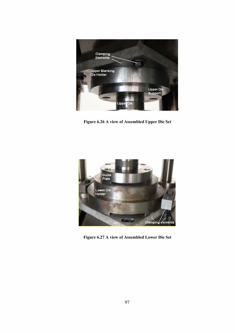
Figure 6.26 A view of Assembled Upper Die Set
Figure 6.27 A view of Assembled Lower Die Set
97

Figure 6.28 Modular Blanking Die Set
6.3 Manufacturing of the Blanks by using Blanking Process
As discussed in section 6.1, blank material has been chosen as CuZn30. Blank
dimensions and preparation are very important for the quality of coining. Before
preparation of the necessary blanks, the dimensions of the workpiece should be
determined according to the volume of the finished medallion.
The outer diameter of the medallion was chosen to be 90 mm. The thickness was
set as 5 mm and a relief height is set as 0.5 mm considering the esthetical
criteria, proportionality of the current medallion geometries and the available
sheet material thickness in the market.
In order to fill die cavities the diameter of the blanks should be smaller than the
desired medallion diameter. As discussed in Chapter 2, the blanks are cut from
98

the sheet with a width of 100 mm and a pitch of 94 mm which is the sum of the
blank diameter (D) and the distance between blanks that will be cut out (b).
Brass tonnage, PBL, necessary for the blanking operation can be simply
calculated by using the Eq.2.1. The blank diameter, d, is 89 mm, the blank
thickness, t, is 5 mm and the shear strength of CuZn30, SS, is 240 MPa as seen
in Appendix B. Therefore, necessary tonnage for blanking process is evaluated
below.
( ) Sd t Sπ× × × (6.1.a) BLP
BLP 89 5 240π×
(6.1.c)
× × (6.1.b)
33
(6.1.d)
BLP 5355N
BLP 34tons
This result shows that 200 ton Dirinler Eccentric Press available in METU-
BILTIR Center is capable for the manufacturing of the blanks for the coining of
the medallion.
6.4 Real Life Experiments of Blanking
After the modular blank dies were manufactured with desired properties, blanks
were sheared from brass sheets by using Dirinler 200 tones trimming press to
achieve the desired quality of production.
The sheet metal of brass was bought in the dimension of 2000x680x5 mm. The
strips were cut from this sheet to dimensions of 115x680 mm as seen in Figure
6.29.
99
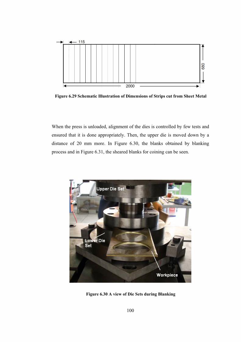
Figure 6.29 Schematic Illustration of Dimensions of Strips cut from Sheet Metal
When the press is unloaded, alignment of the dies is controlled by few tests and
ensured that it is done appropriately. Then, the upper die is moved down by a
distance of 20 mm more. In Figure 6.30, the blanks obtained by blanking
process and in Figure 6.31, the sheared blanks for coining can be seen.
Figure 6.30 A view of Die Sets during Blanking
100
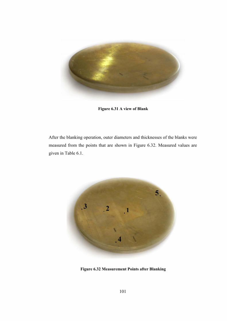
Figure 6.31 A view of Blank
After the blanking operation, outer diameters and thicknesses of the blanks were
measured from the points that are shown in Figure 6.32. Measured values are
given in Table 6.1.
Figure 6.32 Measurement Points after Blanking
101
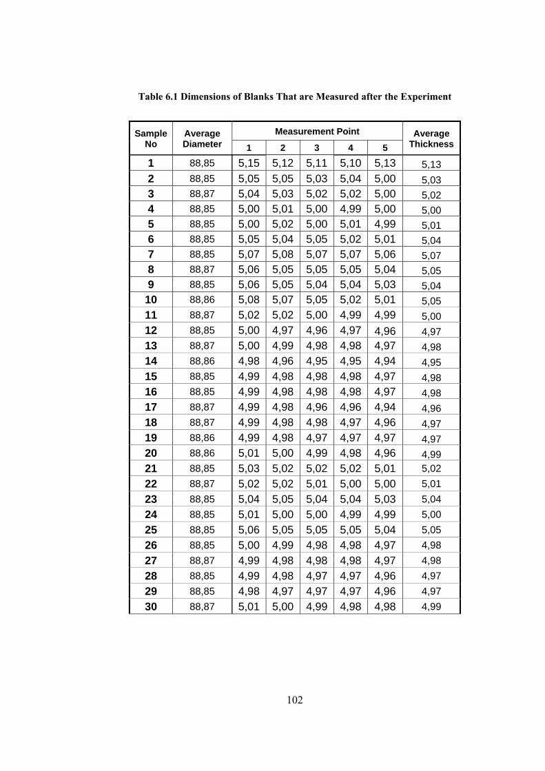
102
Table 6.1 Dimensions of Blanks That are Measured after the Experiment
Sample No
Average Diameter
Measurement Point Average Thickness 1 2 3 4 5
1 88,85 5,15 5,12 5,11 5,10 5,13 5,13 2 88,85 5,05 5,05 5,03 5,04 5,00 5,03 3 88,87 5,04 5,03 5,02 5,02 5,00 5,02 4 88,85 5,00 5,01 5,00 4,99 5,00 5,00 5 88,85 5,00 5,02 5,00 5,01 4,99 5,01 6 88,85 5,05 5,04 5,05 5,02 5,01 5,04 7 88,85 5,07 5,08 5,07 5,07 5,06 5,07 8 88,87 5,06 5,05 5,05 5,05 5,04 5,05 9 88,85 5,06 5,05 5,04 5,04 5,03 5,04 10 88,86 5,08 5,07 5,05 5,02 5,01 5,05 11 88,87 5,02 5,02 5,00 4,99 4,99 5,00 12 88,85 5,00 4,97 4,96 4,97 4,96 4,97 13 88,87 5,00 4,99 4,98 4,98 4,97 4,98 14 88,86 4,98 4,96 4,95 4,95 4,94 4,95 15 88,85 4,99 4,98 4,98 4,98 4,97 4,98 16 88,85 4,99 4,98 4,98 4,98 4,97 4,98 17 88,87 4,99 4,98 4,96 4,96 4,94 4,96 18 88,87 4,99 4,98 4,98 4,97 4,96 4,97 19 88,86 4,99 4,98 4,97 4,97 4,97 4,97 20 88,86 5,01 5,00 4,99 4,98 4,96 4,99 21 88,85 5,03 5,02 5,02 5,02 5,01 5,02 22 88,87 5,02 5,02 5,01 5,00 5,00 5,01 23 88,85 5,04 5,05 5,04 5,04 5,03 5,04 24 88,85 5,01 5,00 5,00 4,99 4,99 5,00 25 88,85 5,06 5,05 5,05 5,05 5,04 5,05 26 88,85 5,00 4,99 4,98 4,98 4,97 4,98 27 88,87 4,99 4,98 4,98 4,98 4,97 4,98 28 88,85 4,99 4,98 4,97 4,97 4,96 4,97 29 88,85 4,98 4,97 4,97 4,97 4,96 4,97 30 88,87 5,01 5,00 4,99 4,98 4,98 4,99
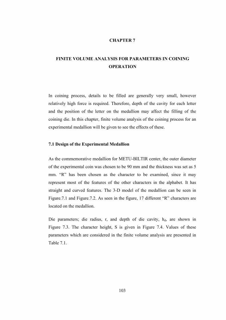
CHAPTER 7
FINITE VOLUME ANALYSIS FOR PARAMETERS IN COINING
OPERATION
In coining process, details to be filled are generally very small, however
relatively high force is required. Therefore, depth of the cavity for each letter
and the position of the letter on the medallion may affect the filling of the
coining die. In this chapter, finite volume analysis of the coining process for an
experimental medallion will be given to see the effects of these.
7.1 Design of the Experimental Medallion
As the commemorative medallion for METU-BILTIR center, the outer diameter
of the experimental coin was chosen to be 90 mm and the thickness was set as 5
mm. “R” has been chosen as the character to be examined, since it may
represent most of the features of the other characters in the alphabet. It has
straight and curved features. The 3-D model of the medallion can be seen in
Figure.7.1 and Figure.7.2. As seen in the figure, 17 different “R” characters are
located on the medallion.
Die parameters; die radius, r, and depth of die cavity, hd, are shown in
Figure 7.3. The character height, S is given in Figure 7.4. Values of these
parameters which are considered in the finite volume analysis are presented in
Table 7.1.
103

Figure 7.1 3-D Model of the Medallion
Figure 7.2 Lines of Relief with Respect to Parameters
104
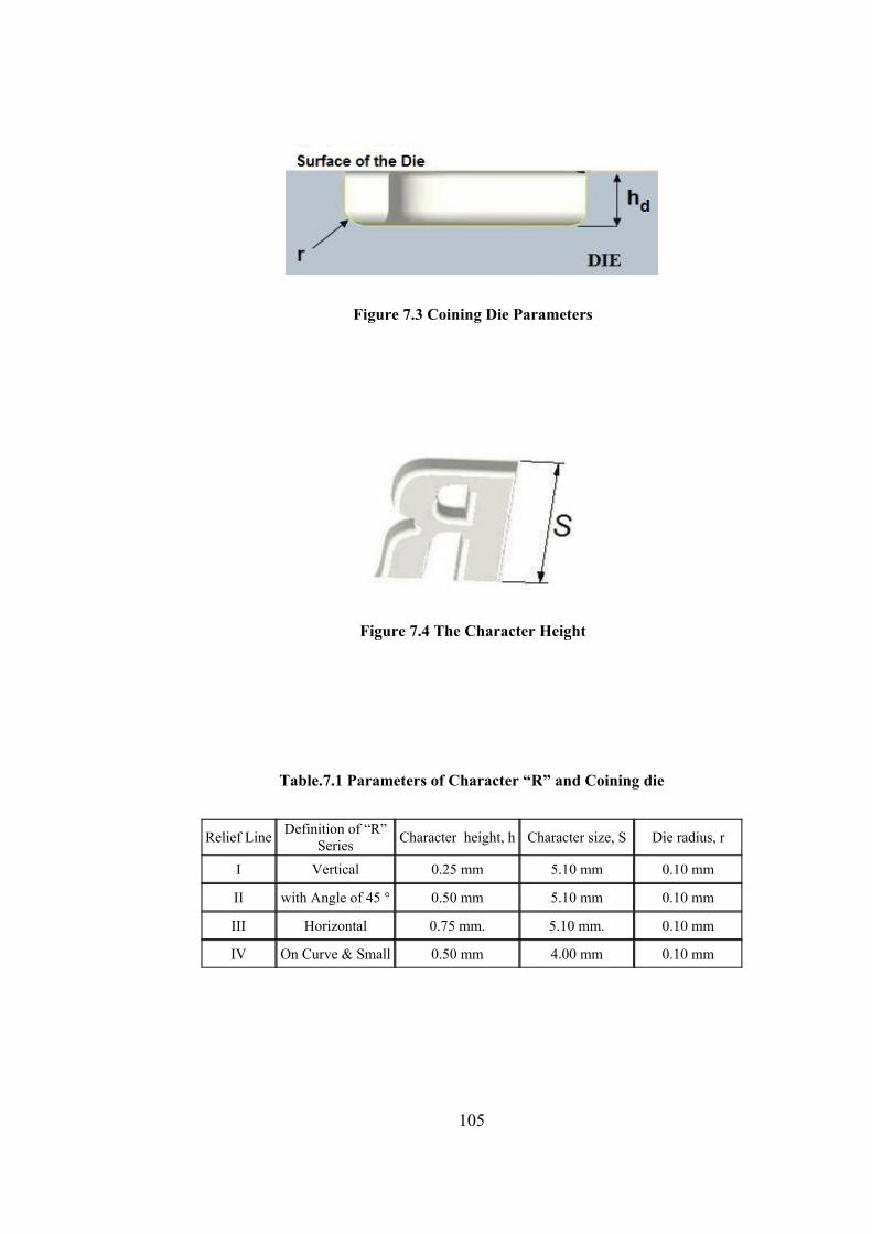
Figure 7.3 Coining Die Parameters
Figure 7.4 The Character Height
Table.7.1 Parameters of Character “R” and Coining die
Relief Line Definition of “R” Series Character height, h Character size, S Die radius, r
I Vertical 0.25 mm 5.10 mm 0.10 mm
II with Angle of 45 ° 0.50 mm 5.10 mm 0.10 mm
III Horizontal 0.75 mm. 5.10 mm. 0.10 mm
IV On Curve & Small 0.50 mm 4.00 mm 0.10 mm
105

7.2 Simulation Results for Experimental Medallion with “R” Characters
During the finite volume simulations, MSC.SuperForge simulation parameters
necessary for the analysis are kept the same as that of coining of
commemorative medallion. Furthermore, simulations are conducted for the
room temperature (20°C), 400°C (temperature below recrystallization zone) and
800°C (temperature for hot working zone). The temperature values are chosen
by considering Cu-Zn phase diagram given in Figure 7.5. The results of the
simulation of experimental medallion are given in the order of the die filling
analysis, effective stress distribution and effective plastic strain distribution in
Figures 7.6-7.22.
Figure 7.5 Cu-Zn Phase Diagram [35]
106
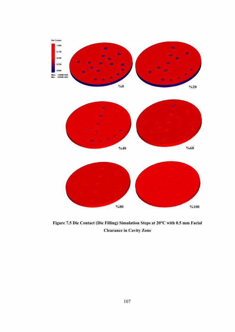
Figure 7.5 Die Contact (Die Filling) Simulation Steps at 20°C with 0.5 mm Facial
Clearance in Cavity Zone
107
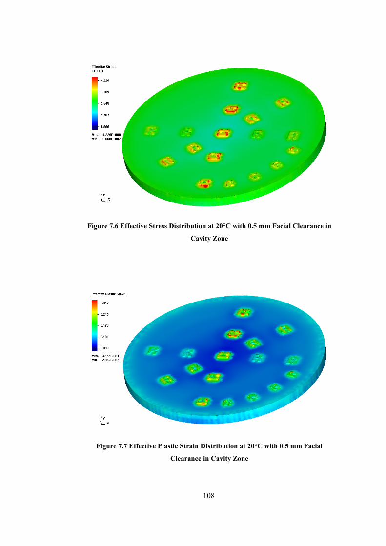
Figure 7.6 Effective Stress Distribution at 20°C with 0.5 mm Facial Clearance in
Cavity Zone
Figure 7.7 Effective Plastic Strain Distribution at 20°C with 0.5 mm Facial
Clearance in Cavity Zone
108
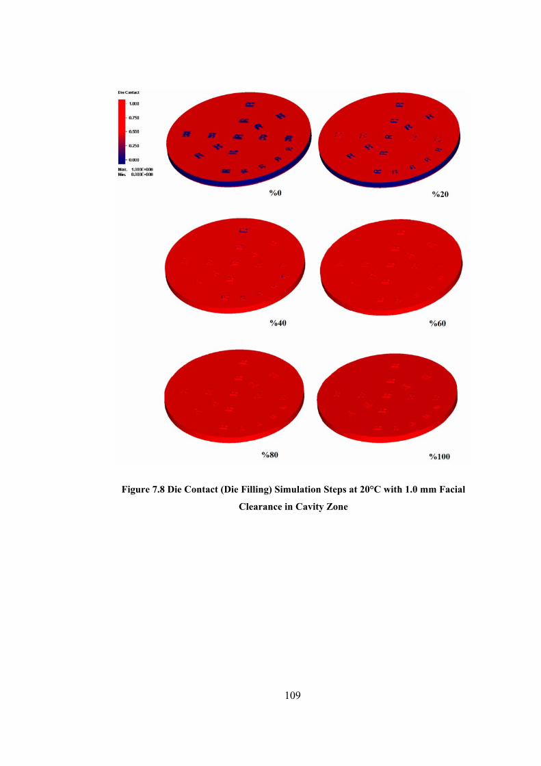
Figure 7.8 Die Contact (Die Filling) Simulation Steps at 20°C with 1.0 mm Facial
Clearance in Cavity Zone
109

Figure 7.9 Effective Stress Distribution at 20°C with 1.0 mm Facial Clearance in
Cavity Zone
Figure 7.10 Effective Plastic Strain Distribution at 20°C with 1.0 mm Facial
Clearance in Cavity Zone
110

Figure 7.11 Die Contact (Die Filling) Simulation Steps at 400°C with 0.5 mm Facial
Clearance in Cavity Zone
111
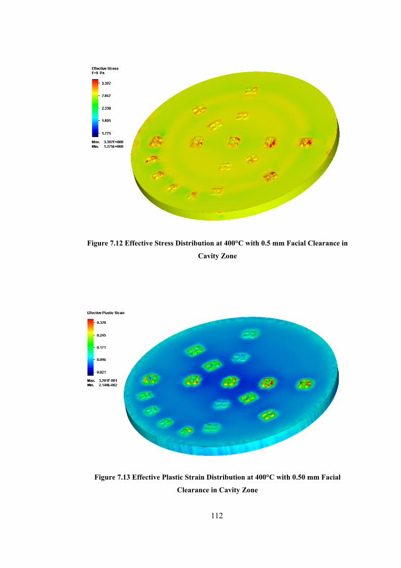
Figure 7.12 Effective Stress Distribution at 400°C with 0.5 mm Facial Clearance in
Cavity Zone
Figure 7.13 Effective Plastic Strain Distribution at 400°C with 0.50 mm Facial
Clearance in Cavity Zone
112
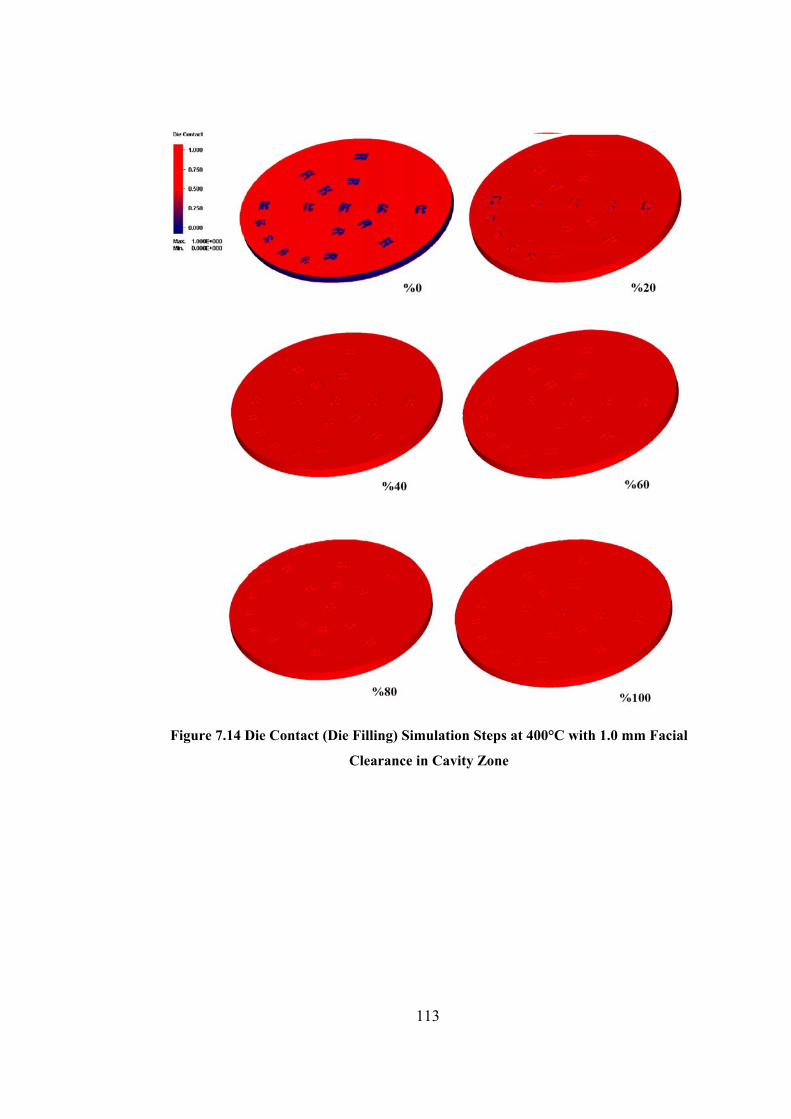
Figure 7.14 Die Contact (Die Filling) Simulation Steps at 400°C with 1.0 mm Facial
Clearance in Cavity Zone
113
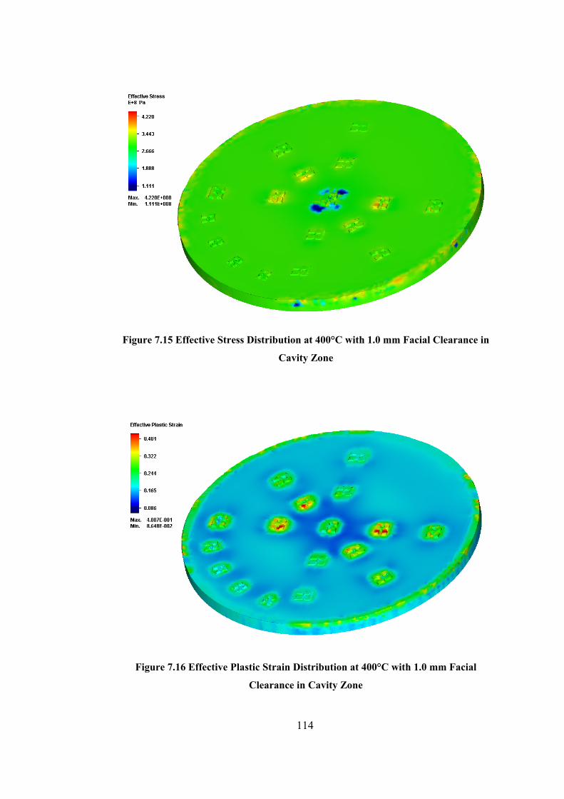
Figure 7.15 Effective Stress Distribution at 400°C with 1.0 mm Facial Clearance in
Cavity Zone
Figure 7.16 Effective Plastic Strain Distribution at 400°C with 1.0 mm Facial
Clearance in Cavity Zone
114
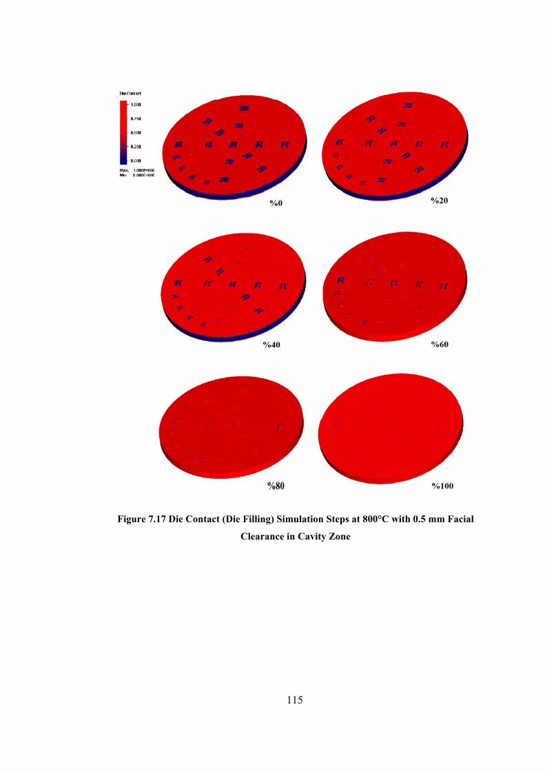
Figure 7.17 Die Contact (Die Filling) Simulation Steps at 800°C with 0.5 mm Facial
Clearance in Cavity Zone
115
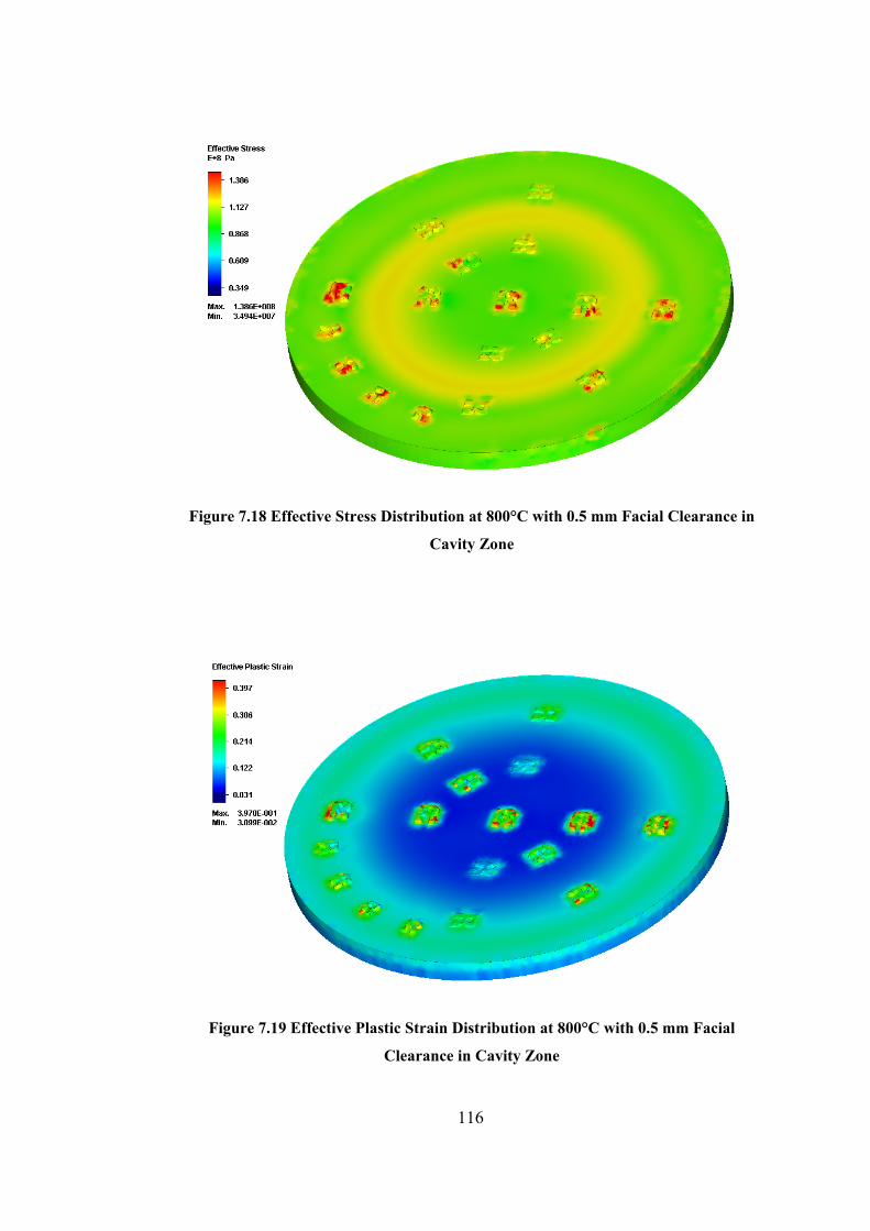
Figure 7.18 Effective Stress Distribution at 800°C with 0.5 mm Facial Clearance in
Cavity Zone
Figure 7.19 Effective Plastic Strain Distribution at 800°C with 0.5 mm Facial
Clearance in Cavity Zone
116
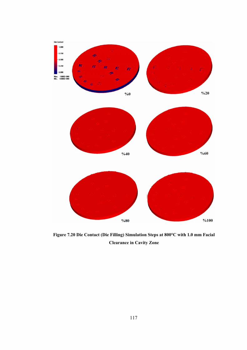
Figure 7.20 Die Contact (Die Filling) Simulation Steps at 800°C with 1.0 mm Facial
Clearance in Cavity Zone
117
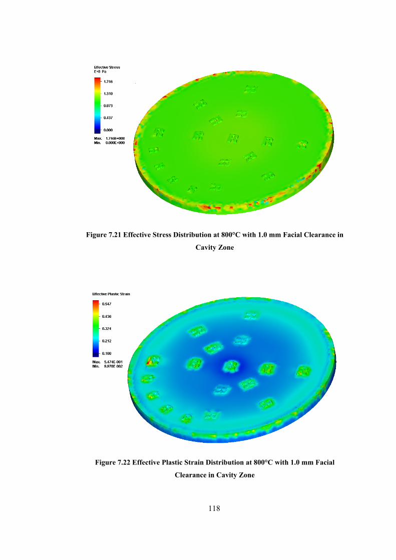
Figure 7.21 Effective Stress Distribution at 800°C with 1.0 mm Facial Clearance in
Cavity Zone
Figure 7.22 Effective Plastic Strain Distribution at 800°C with 1.0 mm Facial
Clearance in Cavity Zone
118
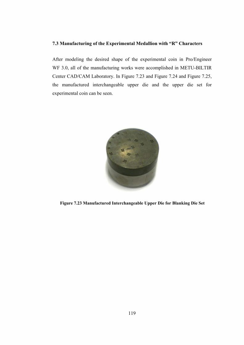
7.3 Manufacturing of the Experimental Medallion with “R” Characters
After modeling the desired shape of the experimental coin in Pro/Engineer
WF 3.0, all of the manufacturing works were accomplished in METU-BILTIR
Center CAD/CAM Laboratory. In Figure 7.23 and Figure 7.24 and Figure 7.25,
the manufactured interchangeable upper die and the upper die set for
experimental coin can be seen.
Figure 7.23 Manufactured Interchangeable Upper Die for Blanking Die Set
119
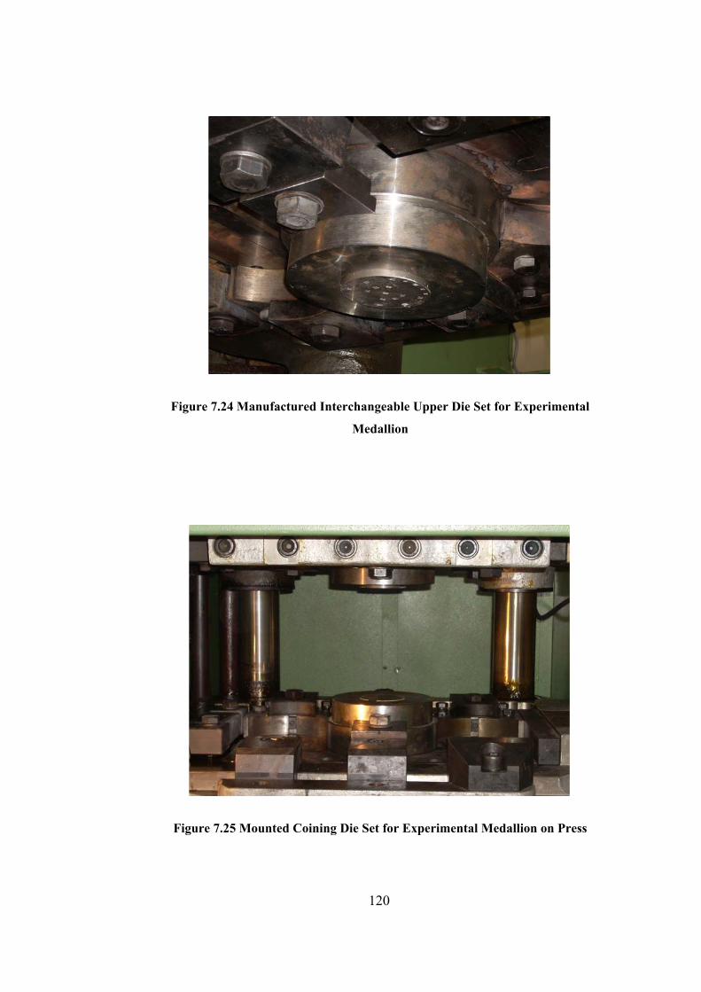
Figure 7.24 Manufactured Interchangeable Upper Die Set for Experimental
Medallion
Figure 7.25 Mounted Coining Die Set for Experimental Medallion on Press
120

CHAPTER 8
CONCLUSIONS AND FUTURE WORK
8.1 General Conclusions
In this study, design and analysis for medallion production for both coining and
blanking processes have been realized. Afterwards, real life experiments have
been conducted and following conclusions have been reached;
• An alternative methodology for coining operation has been introduced
which includes CAD/CAM applications to the design and production
phases. The design of medallions and coins are still performed by
sketching the paper and transferring to the dies by several intermediate
steps in mints. This time consuming procedure results in material waste
and time consumption. In this study, instead of preparing molds for the
engraving machine and reading details with laser reader of it, the
medallion has been designed in CAD environment and NC codes have
been prepared by using CAM software and NC codes have been directly
transferred to the CNC machine. By this way, significant time can be
saved.
• Design of a modular blanking die set for medallion production has been
done successfully. The proposed blanking die set consists of two
modules which are the upper die set and lower die set. In this modular
design, the modules can be easily changed in the case of production of
blanks with different diameter values of 30-90 mm.
• Design of a modular coining die set for medallion production has been
successfully realized. The coining die set consists of two dies which are
the upper die, the lower die and auxiliary elements such as supporting
121

dies, fixing bolt, ejector pins and keys. The modular components of the
die set can be easily changed according to the required diameter and the
design of the medallion.
• The finite volume analysis of the particular medallion which has 17 “R”
characters at different locations is performed for temperatures of 20°C,
400°C and 800°C by a commercially available finite volume program to
see the effects of character height, S, depth of die cavity, hd and location.
• According to the successful simulation results, the modular die sets for
blanking and coining processes for production of medallion have been
manufactured in METU-BILTIR Center CAD/CAM Laboratory.
• A commemorative medallion for the Opening Ceremony of
METU-BILTIR Center Forging Research and Application Laboratory
has been designed. A modular die set for the coining process of this
medallion has been designed and the finite volume analysis has been
done by using MSC.SuperForge. At the end of the experiments, the
medallion is successfully coined with the desired geometry.
8.2 Future Work
Suggested future works can be stated as below.
• Experiments for the coining of the experimental medallion with “R”
characters should be conducted.
• More experiments should be done to compare the results with CAE
results.
• Smeral 1000-ton Mechanical Press which is available in METU-BILTIR
Center was designed for hot forging operations. Therefore, the coining
process can be further analyzed by using a cold forging press.
• The finite volume simulations could also be conducted by using a Finite
Element Simulation program.
• The study may be extended for smaller medallions.
122

• Coining process may be performed for two-sided medallions.
• Coining with different sizes having ornamented edge and/or coinage
with collar may be analyzed.
• Coining for different geometries may be analyzed.
• Coining of medallions with different materials may be studied.
• Tool life and wear analyses may be studied for the dies.
123
REFERENCES
[1] G., Sahcs, “Principles and Methods of Sheet Metal Fabricating”, Reinhold
Publishing Corporation, 3td Edition, 1956.
[2] H., Boyer, “Metals Handbook Forming and Forging”, ASM Handbook
Committee, 9th Edition, Vol 14, 1988.
[3] Private Communications with Turkish Mint in Istanbul.
[4] http://www.controllaser.com [On-Line], Available at,
http://www.controllaser.com/products/products.asp, Last accessed date: 18.08.2008.
[5] Royal Australian Mint, [On-Line], Available at,
http://www.ramint.gov.au/making_coins/body_making_coins.cfm,
Last accessed date: 18.08.2008.
[6] Bech, J., Bay, N., Eriksen, M., “Entrapment and Escape of Liquid Lubricant
in Metal Forming”, Department of Manufacturing Engineering, Technical
University of Denmark, Denmark, Wear 232_1999.134–139.
[7] Choi, H., Lee, J., Bijun, S., Kang, B., “Development of a Three Dimensional
Finite Element Program for Metal Forming and Its Application to Precision
Coining”, Journal of Materials Processing Technology, 72 (1997) 396–402.
[8] Byun, S., Huh, B., Kang, B., “Finite-Element Analysis and Design in the
Combined Precision Forming of Bending and Coining with Experimental
Measurement”, Journal of Materials Processing Technology, 94 (1999) 167±17.
124

[9] Ike, H., “Surface Deformation vs. Bulk Plastic Deformation-A Key for
Microscopic Control of Surfaces in Metal Forming”, Journal of Materials
Processing Technology, 138 (2003) 250–255.
[10]. Wang, C.J., Shan, D.B., Zhou, J. Guo, B., Sun, L.N., “Size Effects of The
Cavity Dimension on the Microforming Ability During Coining Process”,
Journal of Materials Processing Technology, 187–188 (2007) 256–259.
[11] Choi, H., Kim, Y., Kang, B., “Coining Process Design by the Three
Dimensional Backward Tracing Scheme of the Finite Element Method and Its
Experimental Configuration”, JSME International Journal, C 45 1 (2002).
[12] Thome, M., Hirt, G., Rattay, B., “Metal Flow and Die Filling in Coining of
Micro Structures with and without Flash”, Advanced Materials Research Vols.,
6-8 (2005) pp631-638.
[13] Davis, P.J., Wall, M.A., Hodge, N.E., Schwartz, A.J., “Preliminary Report
on Coining of Targets”, La Wrence Livermore National Laboratory, UCRL-TR-
205723, August 2004.
[14] Mundell, R. A., “Birth of Coinage”, Department of Economics Discussion
Paper Series, Columbia University, New York, 2002.
[15] John Lynn & Company [On-Line], Available at,
http://lynncoins.com/dictionary_of_coin_collecting_terms.htm#R, Last accessed
date: 18.08.2008.
[16] The United States Mint [On-Line], Available at,
http://www.usmint.gov/kids/campCoin/collectorsWorkshop/getAClue/case04/ot
herClues.cfm, Last accessed date: 18.08.2008.
125
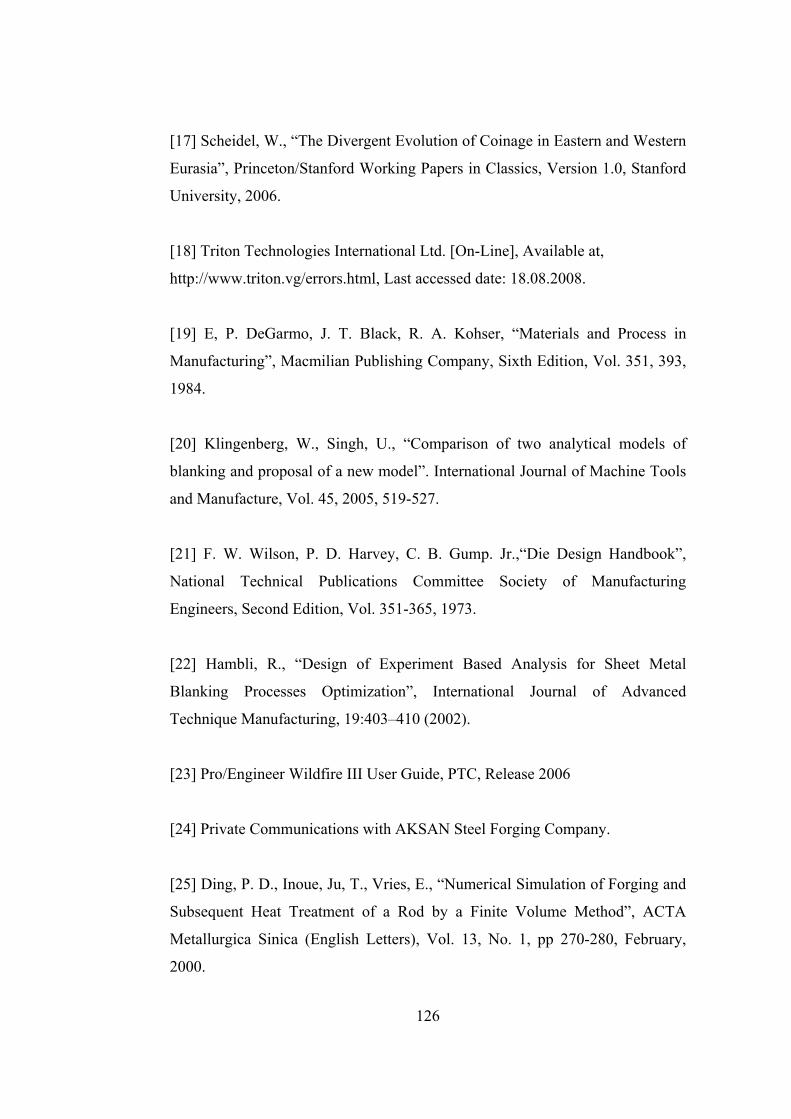
[17] Scheidel, W., “The Divergent Evolution of Coinage in Eastern and Western
Eurasia”, Princeton/Stanford Working Papers in Classics, Version 1.0, Stanford
University, 2006.
[18] Triton Technologies International Ltd. [On-Line], Available at,
http://www.triton.vg/errors.html, Last accessed date: 18.08.2008.
[19] E, P. DeGarmo, J. T. Black, R. A. Kohser, “Materials and Process in
Manufacturing”, Macmilian Publishing Company, Sixth Edition, Vol. 351, 393,
1984.
[20] Klingenberg, W., Singh, U., “Comparison of two analytical models of
blanking and proposal of a new model”. International Journal of Machine Tools
and Manufacture, Vol. 45, 2005, 519-527.
[21] F. W. Wilson, P. D. Harvey, C. B. Gump. Jr.,“Die Design Handbook”,
National Technical Publications Committee Society of Manufacturing
Engineers, Second Edition, Vol. 351-365, 1973.
[22] Hambli, R., “Design of Experiment Based Analysis for Sheet Metal
Blanking Processes Optimization”, International Journal of Advanced
Technique Manufacturing, 19:403–410 (2002).
[23] Pro/Engineer Wildfire III User Guide, PTC, Release 2006
[24] Private Communications with AKSAN Steel Forging Company.
[25] Ding, P. D., Inoue, Ju, T., Vries, E., “Numerical Simulation of Forging and
Subsequent Heat Treatment of a Rod by a Finite Volume Method”, ACTA
Metallurgica Sinica (English Letters), Vol. 13, No. 1, pp 270-280, February,
2000.
126

[26] A. E., Tekkaya, “Current State and Future Developments in the Simulation
of Forming Processes”, Proc. 30th Plenary Meeting of the International Cold
Forging Croup ICFG, Den Bosch, September 1997, pp. 1-10.
[27] Slagter, W. J., Florie, C. J. L., Venis, A. C. J., “Forging Simulation Tool
Based on Breakthrough Technology”, MSC.Software Corporation, The
Netherlands.
[28] V. Bhavin Mehta, Ibrahim Al-Zkeri, Jay S. Gunasekera,Jay S., “Evaluation
of MSC.SuperForge for 3D Simulation of Streamlined and Shear Extrusion
Dies”, Ohio University, Athens, Ohio, USA, 2000.
[29] MSC Superforge User Manual
[30] MSC.SuperForge, Material Library
[31] Smeral QLZK UC Die Holder Manual
[32] TS 1845, February 1975
[33] ASSAB KORKMAZ [On-Line], Available at,
http://www.assabkorkmaz.com.html, Last accessed date: 26.05.2008.
[34] Dirinler CDÇH 2000 P HS Die Holder Manual
[35] Faculty of Engineering Ubonrajathanee University Online Document and
Multimedia Learning, http://app.eng.ubu.ac.th/~edocs/f20060805Suriya34.gif,
Last accessed date: 18.01.2008.
[36] Northwest Territorial Mint [On-Line], Available at,
127
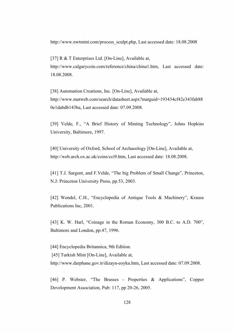
http://www.nwtmint.com/process_sculpt.php, Last accessed date: 18.08.2008
[37] R & T Enterprises Ltd. [On-Line], Available at,
http://www.calgarycoin.com/reference/china/china1.htm, Last accessed date:
18.08.2008.
[38] Automation Creations, Inc. [On-Line], Available at,
http://www.matweb.com/search/datasheet.aspx?matguid=193434cf42e343fab88
0e1dabdb143ba, Last accessed date: 07.09.2008.
[39] Velde, F., “A Brief History of Minting Technology”, Johns Hopkins
University, Baltimore, 1997.
[40] University of Oxford, School of Archaeology [On-Line], Available at,
http://web.arch.ox.ac.uk/coins/cci9.htm, Last accessed date: 18.08.2008.
[41] T.J. Sargent, and F.Velde, “The big Problem of Small Change”, Princeton,
N.J: Princeton University Press, pp.53, 2003.
[42] Wendel, C.H., “Encyclopedia of Antique Tools & Machinery”, Krause
Publications Inc, 2001.
[43] K. W. Harl, “Coinage in the Roman Economy, 300 B.C. to A.D. 700”,
Baltimore and London, pp.47, 1996.
[44] Encyclopedia Britannica, 9th Edition.
[45] Turkish Mint [On-Line], Available at,
http://www.darphane.gov.tr/dizayn-eoyku.htm, Last accessed date: 07.09.2008.
[46] P. Webster, “The Brasses - Properties & Applications”, Copper
Development Association, Pub: 117, pp 20-26, 2005.
128
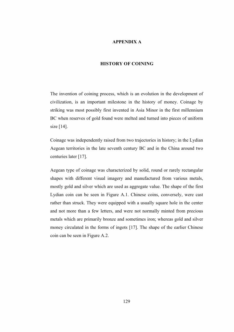
APPENDIX A
HISTORY OF COINING
The invention of coining process, which is an evolution in the development of
civilization, is an important milestone in the history of money. Coinage by
striking was most possibly first invented in Asia Minor in the first millennium
BC when reserves of gold found were melted and turned into pieces of uniform
size [14].
Coinage was independently raised from two trajectories in history; in the Lydian
Aegean territories in the late seventh century BC and in the China around two
centuries later [17].
Aegean type of coinage was characterized by solid, round or rarely rectangular
shapes with different visual imagery and manufactured from various metals,
mostly gold and silver which are used as aggregate value. The shape of the first
Lydian coin can be seen in Figure A.1. Chinese coins, conversely, were cast
rather than struck. They were equipped with a usually square hole in the center
and not more than a few letters, and were not normally minted from precious
metals which are primarily bronze and sometimes iron; whereas gold and silver
money circulated in the forms of ingots [17]. The shape of the earlier Chinese
coin can be seen in Figure A.2.
129
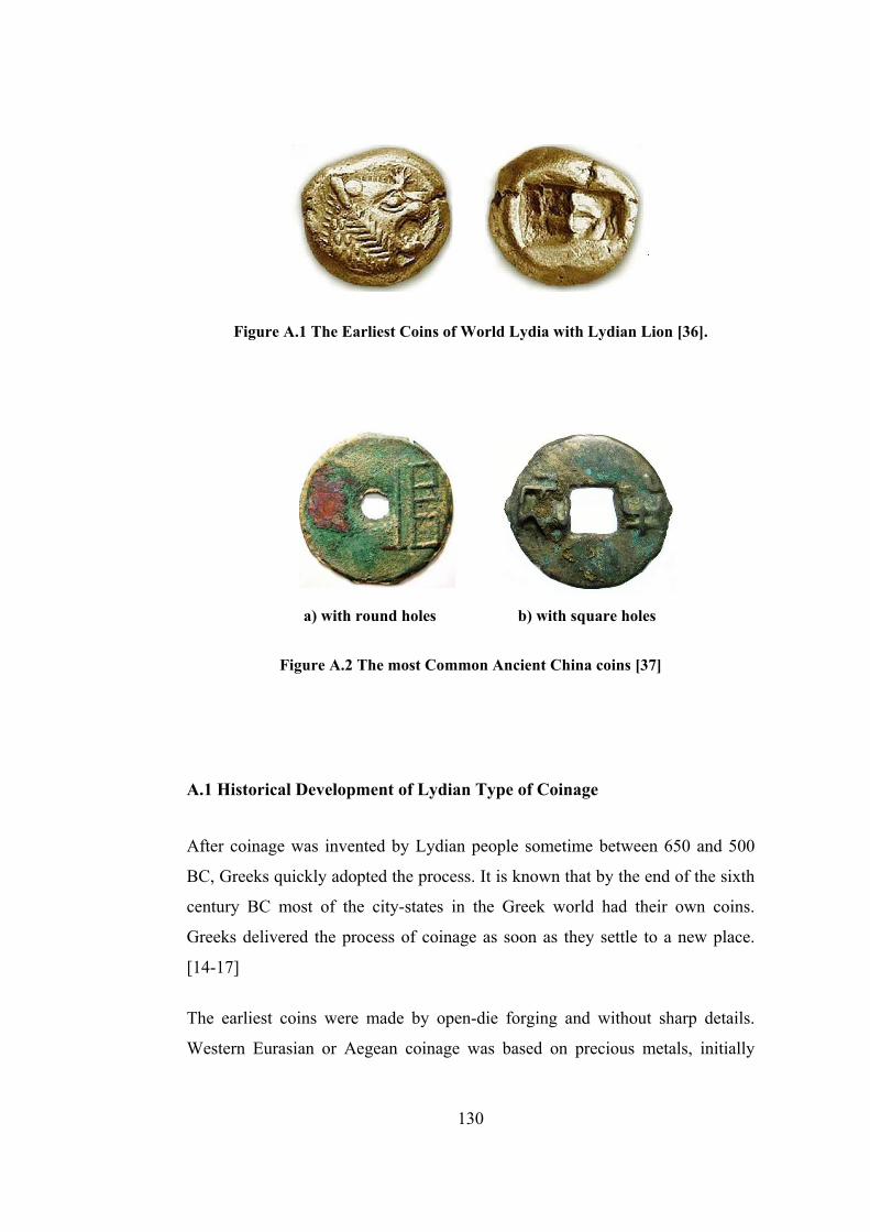
Figure A.1 The Earliest Coins of World Lydia with Lydian Lion [36].
a) with round holes b) with square holes
Figure A.2 The most Common Ancient China coins [37]
A.1 Historical Development of Lydian Type of Coinage
After coinage was invented by Lydian people sometime between 650 and 500
BC, Greeks quickly adopted the process. It is known that by the end of the sixth
century BC most of the city-states in the Greek world had their own coins.
Greeks delivered the process of coinage as soon as they settle to a new place.
[14-17]
The earliest coins were made by open-die forging and without sharp details.
Western Eurasian or Aegean coinage was based on precious metals, initially
130

electrum which is a naturally yellow gold-silver alloy and then on gold and
silver as separately. Silver quickly became the dominant metal of the developing
Aegean coinage system. After its adaptation, silver coinage spread along Greek
overseas migration, to Black Sea region in the early sixth century BC, to Sicily
and southern Italy in the middle of the sixth century BC, and to the coastal
settlements in Cyrene, Spain and Provence. For a quarter of a millennium or so,
production of Greek-style precious-metal coins was largely confined to Greek
populations and those in close contact with them. From the late sixth century the
coinage has brought to the northern Aegean in south-western Asia Minor.
Although coin use has been relatively rare beyond the western of Mediterranean
periphery, the Lydian imitation of Aegean coinage was adopted and modified by
the Achaemenid Empire, predecessors of Persians, in the period of war with
Greeks in the first half of the fifth century BC. Greek-style coin came to be
produced in large quantities all over the former Persian Empire, from Eastern
Iran to Mesopotamia, Syria, Egypt and north-western India which had
previously begun to produce punch marked silver bars [17].
In the west, the spread of Greek-style coins is difficult to date, although it
appears that this process was not developed until the second century BC,
resulting in varied output in Spain, Gaul, the Alpine region and the Balkans, as
well as in the southern half of Britain [17]. In Italy, Rome was gradually
superseded by the introduction of Greek-style silver coins, contrary to tradition
of producing heavy metal bars of bronze. Silver increasingly exceeded the
bronze money by the second century BC. Roman expansion initiated a
protracted process of monetary unification [38].
From the beginning of medieval period to Renaissance, three steps of coinage
that are applied today were mainly identical. The first step is bringing the metal
into desired shaped sheets; the second one is cutting blanks from these sheets
and the last one is striking the coins [39]. The process was based on the striking
of the upper die several times with a hammer onto the spike shaped tool placed
on a wooden block between the legs of worker. The operation can be seen
131
schematically in Figure A.3. This dies were made locally by the special
experienced workers in the mint. The indents of punches are engraved firstly
and the dies are used to produce the dies. Each step is necessarily done by
experienced workers whose trade is hereditary [39].
Figure A.3 Schematic illustration of The Earliest Coining Process [40].
There are lots of drawbacks when applying this method of striking, some of
which are forgery, low quality and not standardized sizes and weight. The
production of coins is performed by everyday tools. Therefore, faults of imprint
on the coin are common and it is difficult to distinguish the legal patterns from
the forged ones. [40].
The minting process was developed mechanically during the Renaissance when
the art of medal making began in Italy in the 1430s; same inventions were done
to produce the complicated and high-quality medals designs. Medals were
usually cast at that time but in the 16th century the demand for strike medals had
increased. Some inventions which appear due to the necessity for producing the
complicated and high-quality medals designs and striking them with sufficient
132

force and accuracy firstly appeared in Germany and Switzerland in 1550s and
spread to the region [41]. The innovations can be considered in two ways of
minting which are using a screw-press and using a cylinder press on which the
dies were engraved, thus laminating and striking at the same time.
In France and England, the screw press was brought from Germany and
adopted. On the other hand, the cylinder-press was used in Austria, Germany,
Spain, Italy and Sweden. However, in the 18th century, the screw-press
superseded the cylinder press [42]. In France, the mint was set up by an engineer
named Aubin Olivier which had added a pieced collar to the screw press
powered by water-mills to hold the blank and to avoid striking defects. Because
the coin can be removed after each strike with collars, one single process could
be mechanized. With the automation of screw press by the late 18th century, the
feeding of blanks and the extraction of coins had been made automatic [39].
On the other hand, although the principle was raised from Germany to flatten
the metal, Hans Vogler Jr and Rudolf von Rordorf set up the first cylinder-press
in Zurich in the early 1550s [43]. The cylinders, which were powered by water-
wheels or horses, would be engraved with the coin die so that the coins would
be cut out of the stamped strips. On the other hand, the necessity of the use of
oval shaped dies with employing removable dies could be considered as the
drawback of the machine. Furthermore, generally occurring slightly warped
coins prevent the serration of the edges [39].
A different type of cylinder press which was developed in the 17th century
necessitated the use of a pair of mushroom shaped pieces which were engraved
and inserted in slots of rotating axles. The design, which was known as
Taschenwerk, required pre-cut oval shaped blanks whose passage between the
dies made them round. Although the cylinder press was very popular initially,
the screw press replaced the two cylinder machine because of these
disadvantages [39].
133
Marking the edges of the coin was the most significant development in coining
during 18th century. This process was performed by a casting machine which
had been invented in England and adopted in France in 1685. Casting machine
was employing two steel bars, between which the coin was rolled on a
horizontal surface [39].
The portrait lathe (reducing pantograph) which can be seen in Figure A.4 and
hubbing invented by the Swiss J-P Droz around 1780 were two of the most
important inventions occurred in the late 18th and early 19th century in the area
of coining. The major advantage of this innovation was that coins could be
identically reproduced. Furthermore, steam-driven machines which were
introduced in London mint in 1810 had the ability to produce 70 to 80 coins per
minute. However accommodating the rotation and recoil of the screw caused
technical problems preventing easy adaption of steam engines to the old screw
presses [39].
Lever-press invented in 1817 by D. Uhlhorn, a German engineer in
Grevenbroich near Cologne, could more easily be driven by steam compared to
screw press. Depending on the size of the coin, 30 to 60 coins per minute could
be struck by the lever-press. Uhlhorn’ presses were employed by many mints in
Germany and Austria. A French inventor Thonnelier used the principle of lever-
presses to build Thonnelier press which could strike 40 coins per minute. This
machine first came in use in Paris in 1845 and was in use throughout Europe by
the end of 19th century striking 60 to 120 coins per minute [39,44].
By the late 19th century, the production of subsidiary coinage was entirely
adopted in England. Following England, France (in 1864) and U.S. (in 1850)
laid down the first principle of subsidiary coinage.
134

Figure A.4 The Portrait Lathe or Pantograph [45]
A.2 Historical Development of Chinese Type of Coinage
In the first millennium BC, China had developed a different type of coinage
method based on casting of heavy metals with the shape of traditional and
distinctive characters. The region contains modern China as well as in the
secondary monetary traditions of Korea, Vietnam and Japan.
Earlier round coins cast on similarly shaped disks which were made of valuable
stones according to variable regional weight standards with a variety of legends
but no pictures. Between the late second century BC and the late second century
AD, the concern of the imperial mint was standardizing of the weight and
bringing the larger shapes to agreeable values [17]. Between 960 and 1127,
bronze coins and the necessary iron equipments for casting were in use until
paper money was introduced in 1160. After the withdrawal from circulation in
135

1430s, silver which was brought in the case of large quantities from the New
World and Japan began to use from the mid-sixteenth century. Although Aegean
type of silver coins which was accepted by Europe already was used from then
on, in the Ming period, China did not start the production of completely solid
silver coins until the 1830s. The entire region fully adopted the Aegean type of
coinage process with the western influence and the introduction of foreign
equipment in Japan in 1867, Korea in the 1880s and in China mostly in the late
nineteenth century [14-17].
136

APPENDIX B
PROPERTIES FOR BRASS AND DIE SET MATERIALS
B.1 Properties of Brass, CuZn30
Subcategory: Nonferrous Metal, Copper alloy, Brass
In the cold working operations, the alloys are required high cold ductility which
mostly present at brasses given in Table 6.1. The outstanding feature of them is
their ductility at room temperature. Therefore, brasses can be easily deformed by
forging at the room temperature.
The most ductile one is CuZn30 which contains 30% zinc composed of the
highest copper content of the cold working brasses. It has the optimum
combination of properties of strength, ductility and minimal directionality. It has
also the best corrosion resistance. Medallion has several decorative figures
involving delicate geometries. Therefore, the ductility is an essential
specification of the material and it can be said that CuZn30 is appropriate for
cold forging operations [46].
Cold working brasses of which the properties are given in Table 6.1 are
typically used to make semi-finished products. In order to produce simple
products with noncomplex forming methods, cheaper alloys with lower copper
composition such as CuZn64 or CuZn63 can be used. CuZn10, CuZn15 and
CuZn20 can be used for such processes that their excellent ductility, strength
and corrosion resistance or decorative color and durability may be important
such as decorative architectural applications and costume jewelry [46].
137

Table 6.1 Brasses for Cold Working [46]
Compositional Designation
and EN Number
Relevant Properties
CuZn30 CW505L
Excellent cold ductility. Can been used for deep drawing. As wire, suitable for the most severe cold deformation. The best corrosion resistance.
CuZn37 CW508L
Good general purpose alloy suitable for simple forming.
CuZn10 CW501L
Gilding metal with highest copper content. Very good corrosion resistance. Can be brazed and enameled
CuZn15 CW502L
Similar to CuZn10 with slightly superior mechanical properties.
CuZn20 CW503L
Further improvement in mechanical properties. Corrosion resistance not quite as good as CuZn10. Good for deep drawing.
CuZn20Al CW703R
Common in tube form. Excellent corrosion resistance. Used particularly for applications in dean seawater.
Because of the advantages over and the decorative appearance, the brass DIN
CuZn30 of which properties are given in Appendix A is chosen as the blank
material.
Table B.1 Chemical Composition (%) of CuZn30
Cu Pb Fe Sn Al Zn
69.2 – 70.0 max 0.015 max 0.030 0.1 0.02 Rem.
138
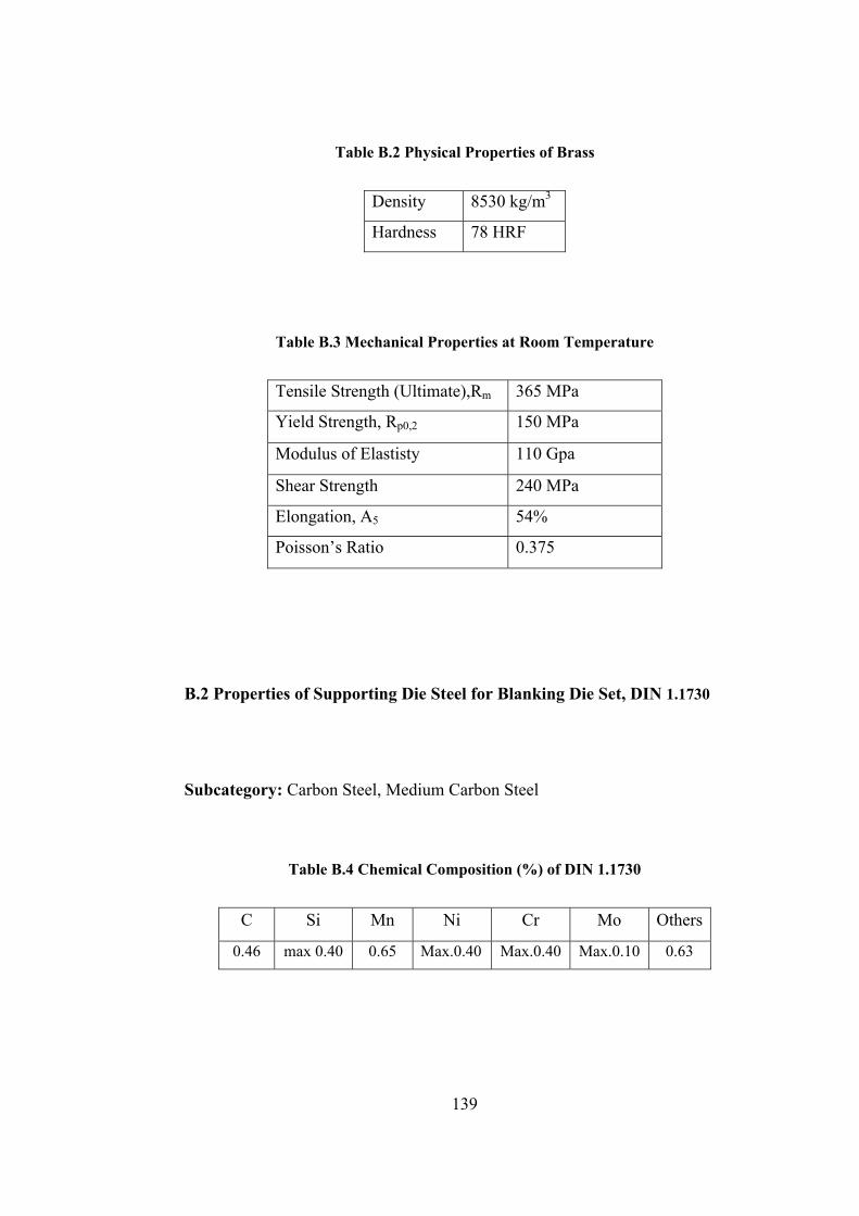
Table B.2 Physical Properties of Brass
Density 8530 kg/m3
Hardness 78 HRF
Table B.3 Mechanical Properties at Room Temperature
Tensile Strength (Ultimate),Rm 365 MPa
Yield Strength, Rp0,2 150 MPa
Modulus of Elastisty 110 Gpa
Shear Strength 240 MPa
Elongation, A5 54%
Poisson’s Ratio 0.375
B.2 Properties of Supporting Die Steel for Blanking Die Set, DIN 1.1730
Subcategory: Carbon Steel, Medium Carbon Steel
Table B.4 Chemical Composition (%) of DIN 1.1730
C Si Mn Ni Cr Mo Others
0.46 max 0.40 0.65 Max.0.40 Max.0.40 Max.0.10 0.63
139
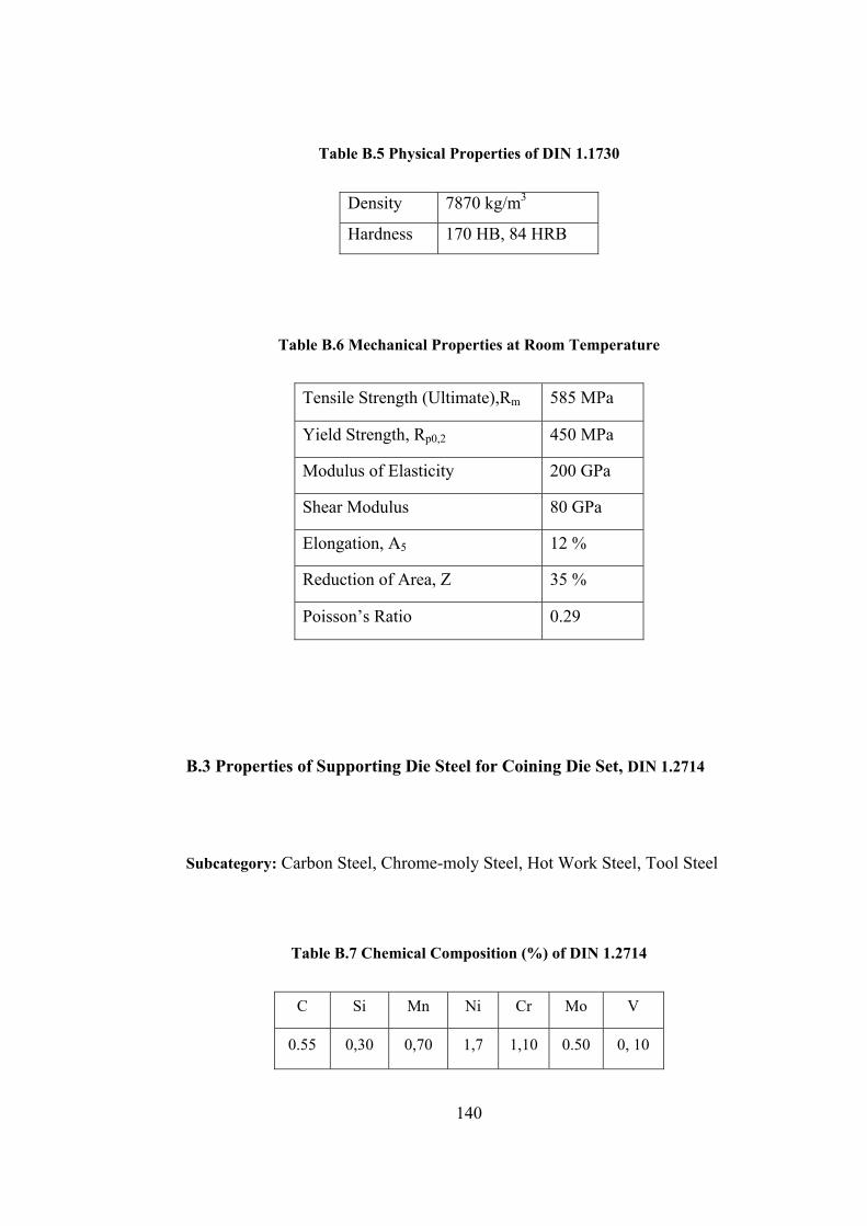
Table B.5 Physical Properties of DIN 1.1730
Density 7870 kg/m3
Hardness 170 HB, 84 HRB
Table B.6 Mechanical Properties at Room Temperature
Tensile Strength (Ultimate),Rm 585 MPa
Yield Strength, Rp0,2 450 MPa
Modulus of Elasticity 200 GPa
Shear Modulus 80 GPa
Elongation, A5 12 %
Reduction of Area, Z 35 %
Poisson’s Ratio 0.29
B.3 Properties of Supporting Die Steel for Coining Die Set, DIN 1.2714
Subcategory: Carbon Steel, Chrome-moly Steel, Hot Work Steel, Tool Steel
Table B.7 Chemical Composition (%) of DIN 1.2714
C Si Mn Ni Cr Mo V
0.55 0,30 0,70 1,7 1,10 0.50 0, 10
140

Table B.8 Physical Properties of DIN 1.2714
Density 7840 kg/m3
Hardness 38-43 HRc-B
Table B.9 Mechanical Properties at Room Temperature of DIN 1.2714
Tensile Strength (Ultimate),Rm 1174 MPa
Yield Strength, Rp0,2 645 MPa
Modulus of Elasticity 215 GPa
Elongation, A5 25 %
Reduction of Area, Z 55 %
Poisson’s Ratio 0.28
B.4 Properties of Modular Die Steel, Sleipner
Subcategory: Chrome-moly Steel, Cold Work Steel, Tool Steel
Table B.10 Chemical Composition (%) of Sleipner Cold Work Tool Steel
C Si Mn Cr Mo V
0,90 0,90 0,50 7.80 2.50 0.50
141
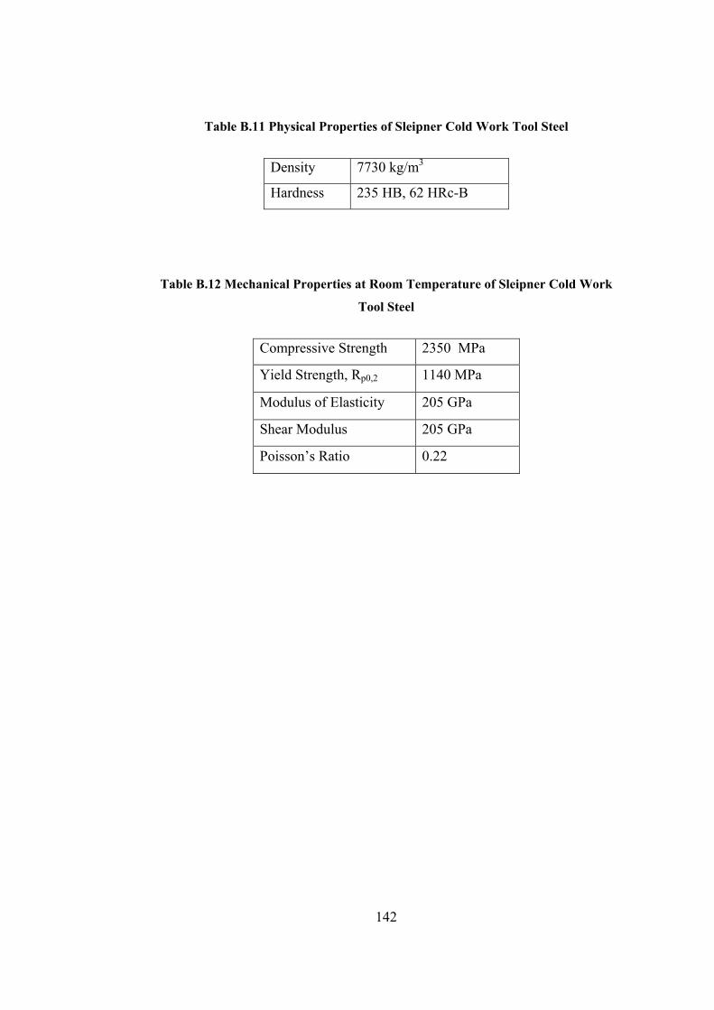
Table B.11 Physical Properties of Sleipner Cold Work Tool Steel
Density 7730 kg/m3
Hardness 235 HB, 62 HRc-B
Table B.12 Mechanical Properties at Room Temperature of Sleipner Cold Work
Tool Steel
Compressive Strength 2350 MPa
Yield Strength, Rp0,2 1140 MPa
Modulus of Elasticity 205 GPa
Shear Modulus 205 GPa
Poisson’s Ratio 0.22
142
APPENDIX C
HEAT TREATMENT OF SLEIPNER
The expected mechanical properties of a tool steel can only be seen if a proper
heat treatment is done after machining. In this study the coining die set is heat
treated in the vacuum furnace available at a private company in Izmir [33]. As
seen in Figure C.1, the coining die set is heated to the austenitizing temperature
which is 1000°C in two sub-stages. When the vacuum furnace is reached to the
austenitizing temperature, it is kept in the furnace until all the sections of the
dies reach to the same temperature. Afterwards, the dies are cooled rapidly with
a cooling rate of 10°C/min. Then the tempering process is applied to the dies.
This heat treatment results in higher toughness values, without sacrificing all of
the hardness and tensile strength gained from the processes applied previously.
The toughness and hardness values are inversely proportional. In this study the
toughness, meaning that the impact absorbing ability of steel without fracture is
more important than the hardness because of the hitting of the dies one to
another. Taking into account to these, the first tempering process is applied
about 2 hours at 580°C. The company reported that after the first tempering the
hardness values of the dies had been measured as 52 HRC. Then the second
tempering process is applied about 2 hours at 610°C and the hardness value had
become 60 HRC. Finally, the third tempering process is applied about 3 hours at
580°C and the hardness value had been measured as 62 HRC.
143

The process can be summarized as;
1000°C Austenitizing (30min) – 36 °C/min rapid cooling rate – 580°C (2hour)
first tempering process (52 HRC) - 610°C (2hour) second tempering process (60
Hrc) - 585°C (3hour) third tempering process (62 HRC)
Figure C.1 Applied Heat Treatment Process
144
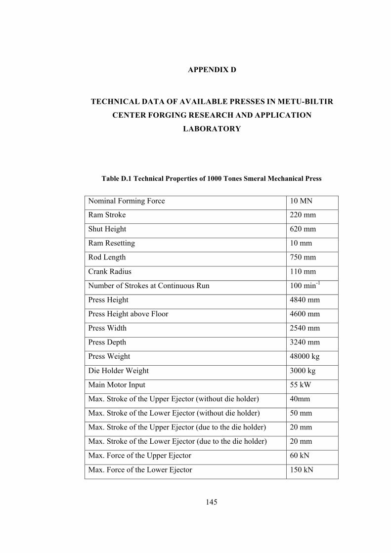
APPENDIX D
TECHNICAL DATA OF AVAILABLE PRESSES IN METU-BILTIR
CENTER FORGING RESEARCH AND APPLICATION
LABORATORY
Table D.1 Technical Properties of 1000 Tones Smeral Mechanical Press
Nominal Forming Force 10 MN
Ram Stroke 220 mm
Shut Height 620 mm
Ram Resetting 10 mm
Rod Length 750 mm
Crank Radius 110 mm
Number of Strokes at Continuous Run 100 min-1
Press Height 4840 mm
Press Height above Floor 4600 mm
Press Width 2540 mm
Press Depth 3240 mm
Press Weight 48000 kg
Die Holder Weight 3000 kg
Main Motor Input 55 kW
Max. Stroke of the Upper Ejector (without die holder) 40mm
Max. Stroke of the Lower Ejector (without die holder) 50 mm
Max. Stroke of the Upper Ejector (due to the die holder) 20 mm
Max. Stroke of the Lower Ejector (due to the die holder) 20 mm
Max. Force of the Upper Ejector 60 kN
Max. Force of the Lower Ejector 150 kN
145
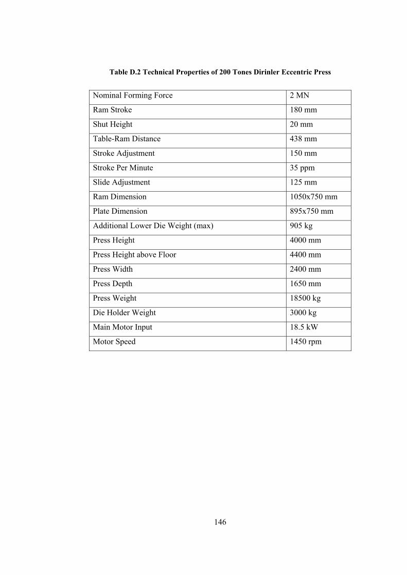
146
Table D.2 Technical Properties of 200 Tones Dirinler Eccentric Press
Nominal Forming Force 2 MN
Ram Stroke 180 mm
Shut Height 20 mm
Table-Ram Distance 438 mm
Stroke Adjustment 150 mm
Stroke Per Minute 35 ppm
Slide Adjustment 125 mm
Ram Dimension 1050x750 mm
Plate Dimension 895x750 mm
Additional Lower Die Weight (max) 905 kg
Press Height 4000 mm
Press Height above Floor 4400 mm
Press Width 2400 mm
Press Depth 1650 mm
Press Weight 18500 kg
Die Holder Weight 3000 kg
Main Motor Input 18.5 kW
Motor Speed 1450 rpm