Embed Size (px)
Citation preview
GI 205Radar Altimeter Indicator
Installation Manual
3700 Osuna Rd NE, Suite 711Albuquerque, NM 87109www.sandia.aero 306295
Manufactured for Garmin International
This document and the information contained herein is the proprietary data of SANDIA aerospace Corporation. No part of this document may be transmitted, reproduced, or copied in any form or by any means without the prior written consent of SANDIA aerospace. Due to SANDIA aerospace’s continued product and quality improvement programs, information contained in this document is subject to change without prior noticeCopyright 2014 SANDIA aerospace Corporation, All right rights reserved. Printed in USA
Information Subject To Export Control Laws
Record of Revisions
1
Revision Date Description Approval1 20140611 DRN 456 L. Harrison2 20150120 ECN 4074 L. Harrison
306295
Table of Contents
2
Record of Revisions ....................................................................................................................................1Table of Contents .......................................................................................................................................2List of Illustrations .....................................................................................................................................3Section 1 General Description ...................................................................................................................41.1 Introduction ................................................................................................................................41.2 RadAlt Indicator Product Description .......................................................................................41.3 Technical Characteristics ...........................................................................................................41.3.1 Physical Characteristics .............................................................................................................41.3.1.1 GI 205 ........................................................................................................................................41.3.2 Electrical ....................................................................................................................................41.3.2.1 Operational Voltage ....................................................................................................................41.3.2.2 Current .......................................................................................................................................41.3.2.3 Display .......................................................................................................................................41.3.2.4 Interfaces ....................................................................................................................................61.4 Certification................................................................................................................................61.4.1 TSO-C87a/ED-30 TSO Functions .............................................................................................61.5 Radar Altimeter Data .................................................................................................................61.6 Radar Altimeter Self Test ...........................................................................................................6Environmental Qualification Form ..........................................................................................................7Section 2 Installation Considerations .......................................................................................................82.1 Mounting Considerations ...........................................................................................................8Section 3 Installation Procedures .............................................................................................................93.1 General .......................................................................................................................................93.2 Equipment Required ..................................................................................................................93.2.1 Supplied .....................................................................................................................................93.2.2 Available ....................................................................................................................................93.3 Electrical Consideration .............................................................................................................93.4 Backshell Assembly ...................................................................................................................93.5 PostInstallationConfiguration ..................................................................................................93.6 Pin Functions ...........................................................................................................................113.7 Continued Airworthiness .........................................................................................................11Appendix A - Outline Drawings .............................................................................................................12Appendix B - Suggested Interconnects ..................................................................................................13
306295
List of Illustrations
3
Figure 1-1 Altitude Display Resolution .................................................................................................4Figure 1-2 Decision Height Setting Resolution .....................................................................................5Figure 1-3 Display Format .....................................................................................................................5Figure 2-1 Panel Cutout Dimensions .....................................................................................................8Figure3-1 PostInstallationConfiguration ..........................................................................................10Figure 3-2 P1 Pin Functions ................................................................................................................11Figure A-1 Outline Dimensions ...........................................................................................................12Figure B-1 Suggested Interconnects .....................................................................................................13
306295
Section 1 General Description1.1 Introduction
This manual describes the installation of the SANDIA aerospace GI 205 Radar Altimeter Indicator, Sandia PartNumber306273-XX.ItisintendedforusebyFAAcertifiedrepairstationstoinstalltheGI205RadarAltimeterIndicatorandincludesbothmechanicalandelectricalinstallationinformation.Systemconfigura-tion and checkout procedures are included. The installer should ensure that all functions are operating accord-ing to their intended purpose in their particular installation.
1.2 Radar Altimeter Indicator Product Description
The GI 205 is 1/2 3ATI indicator designed to operate exclusively with Garmin Radar Altimeters. It provides the pilot with a means of entering Decision Height. The GI 205 displays Radar Altitude from the Garmin Ra-dar Altimeter and sounds an audible alert and displays a visual alert when Decision Height has been crossed.
1.3 Technical Characteristics1.3.1 Physical Characteristics1.3.1.1 GI 205 1/2 3ATI Panel Cut Out Behind Panel Dimensions 1.78”H x 3.5”W x 1.87”L (4.52cm x 8.89cm x 4.75cm) Weight: 0.5 Lbs. (.23 kg)
4
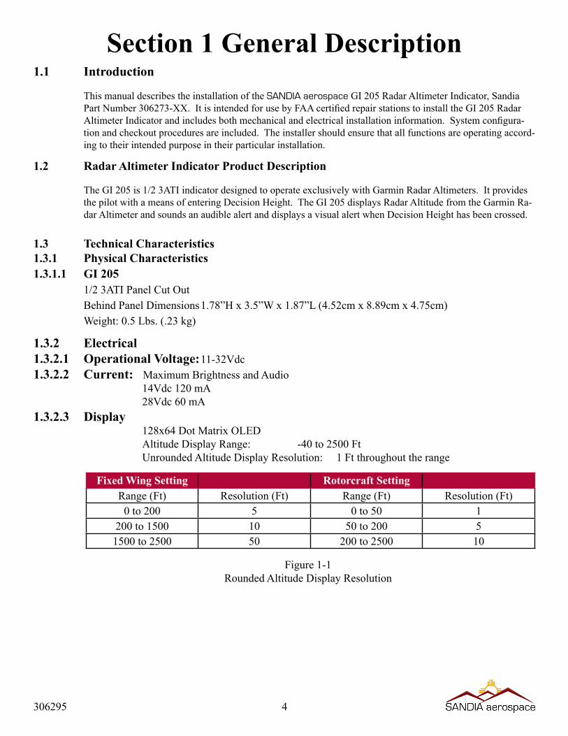
1.3.2 Electrical1.3.2.1 Operational Voltage: 11-32Vdc1.3.2.2 Current: Maximum Brightness and Audio 14Vdc 120 mA 28Vdc 60 mA1.3.2.3 Display 128x64 Dot Matrix OLED Altitude Display Range: -40 to 2500 Ft Unrounded Altitude Display Resolution: 1 Ft throughout the range
Fixed Wing Setting Rotorcraft SettingRange (Ft) Resolution (Ft) Range (Ft) Resolution (Ft)
0 to 200 5 0 to 50 1200 to 1500 10 50 to 200 51500 to 2500 50 200 to 2500 10
Figure 1-1Rounded Altitude Display Resolution
306295
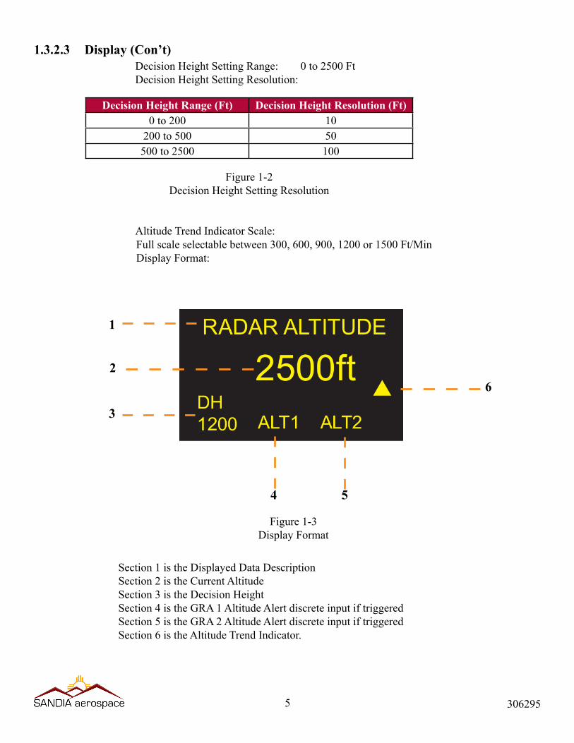
1.3.2.3 Display (Con’t) Decision Height Setting Range: 0 to 2500 Ft Decision Height Setting Resolution:
Decision Height Range (Ft) Decision Height Resolution (Ft)0 to 200 10
200 to 500 50500 to 2500 100
Altitude Trend Indicator Scale: Full scale selectable between 300, 600, 900, 1200 or 1500 Ft/Min Display Format:
1
2
3
6
4 5
Section 1 is the Displayed Data DescriptionSection 2 is the Current AltitudeSection 3 is the Decision HeightSection 4 is the GRA 1 Altitude Alert discrete input if triggeredSection 5 is the GRA 2 Altitude Alert discrete input if triggeredSection 6 is the Altitude Trend Indicator.
5
Figure 1-2Decision Height Setting Resolution
Figure 1-3Display Format
306295
6
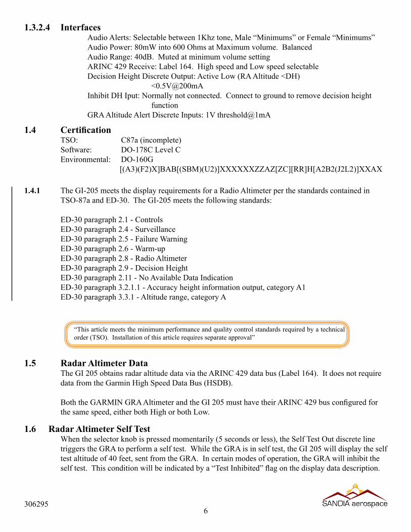
“This article meets the minimum performance and quality control standards required by a technical order (TSO). Installation of this article requires separate approval”
1.4 Certification TSO: C87a (incomplete) Software: DO-178C Level C Environmental: DO-160G [(A3)(F2)X]BAB[(SBM)(U2)]XXXXXXZZAZ[ZC][RR]H[A2B2(J2L2)]XXAX
1.5 Radar Altimeter DataThe GI 205 obtains radar altitude data via the ARINC 429 data bus (Label 164). It does not require data from the Garmin High Speed Data Bus (HSDB).
BoththeGARMINGRAAltimeterandtheGI205musthavetheirARINC429busconfiguredforthe same speed, either both High or both Low.
1.6 Radar Altimeter Self TestWhen the selector knob is pressed momentarily (5 seconds or less), the Self Test Out discrete line triggers the GRA to perform a self test. While the GRA is in self test, the GI 205 will display the self test altitude of 40 feet, sent from the GRA. In certain modes of operation, the GRA will inhibit the selftest.Thisconditionwillbeindicatedbya“TestInhibited”flagonthedisplaydatadescription.
1.3.2.4 Interfaces Audio Alerts: Selectable between 1Khz tone, Male “Minimums” or Female “Minimums” Audio Power: 80mW into 600 Ohms at Maximum volume. Balanced Audio Range: 40dB. Muted at minimum volume setting ARINC 429 Receive: Label 164. High speed and Low speed selectable Decision Height Discrete Output: Active Low (RA Altitude <DH) <0.5V@200mA Inhibit DH Iput: Normally not connected. Connect to ground to remove decision height function GRA Altitude Alert Discrete Inputs: 1V threshold@1mA
306295
1.4.1 The GI-205 meets the display requirements for a Radio Altimeter per the standards contained in TSO-87a and ED-30. The GI-205 meets the following standards:
ED-30 paragraph 2.1 - ControlsED-30 paragraph 2.4 - SurveillanceED-30 paragraph 2.5 - Failure WarningED-30 paragraph 2.6 - Warm-upED-30 paragraph 2.8 - Radio AltimeterED-30 paragraph 2.9 - Decision HeightED-30 paragraph 2.11 - No Available Data IndicationED-30 paragraph 3.2.1.1 - Accuracy height information output, category A1ED-30 paragraph 3.3.1 - Altitude range, category A
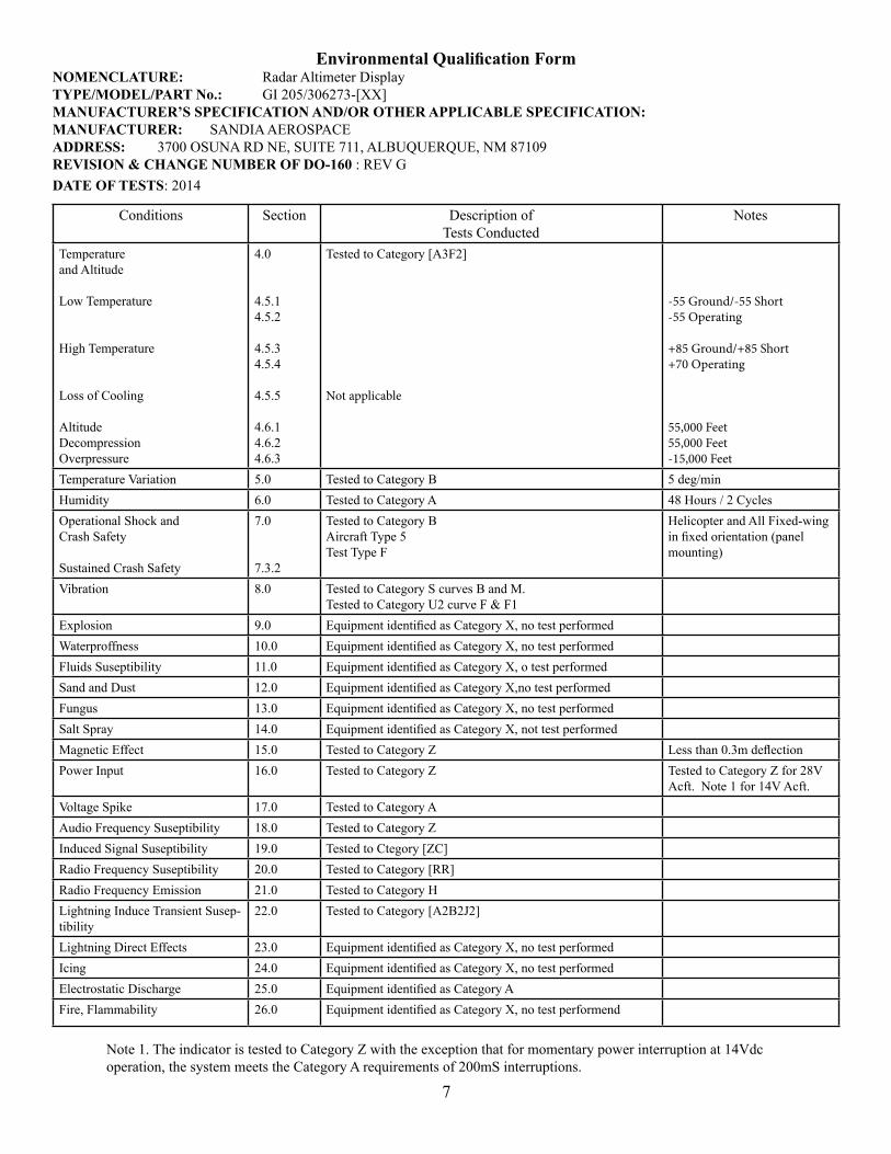
Environmental Qualification FormNOMENCLATURE: Radar Altimeter DisplayTYPE/MODEL/PART No.: GI 205/306273-[XX]MANUFACTURER’S SPECIFICATION AND/OR OTHER APPLICABLE SPECIFICATION:MANUFACTURER: SANDIA AEROSPACEADDRESS: 3700 OSUNA RD NE, SUITE 711, ALBUQUERQUE, NM 87109REVISION & CHANGE NUMBER OF DO-160 : REV GDATE OF TESTS: 2014
Conditions Section Description ofTests Conducted
Notes
Temperatureand Altitude
Low Temperature
High Temperature
Loss of Cooling
AltitudeDecompressionOverpressure
4.0
4.5.14.5.2
4.5.34.5.4
4.5.5
4.6.14.6.24.6.3
Tested to Category [A3F2]
Not applicable
-55 Ground/-55 Short-55 Operating
+85 Ground/+85 Short+70 Operating
55,000 Feet55,000 Feet-15,000 Feet
Temperature Variation 5.0 Tested to Category B 5 deg/minHumidity 6.0 Tested to Category A 48 Hours / 2 CyclesOperational Shock andCrash Safety
Sustained Crash Safety
7.0
7.3.2
Tested to Category BAircraft Type 5Test Type F
Helicopter and All Fixed-wing infixedorientation(panelmounting)
Vibration 8.0 Tested to Category S curves B and M.Tested to Category U2 curve F & F1
Explosion 9.0 EquipmentidentifiedasCategoryX,notestperformedWaterproffness 10.0 EquipmentidentifiedasCategoryX,notestperformedFluids Suseptibility 11.0 EquipmentidentifiedasCategoryX,otestperformedSand and Dust 12.0 EquipmentidentifiedasCategoryX,notestperformedFungus 13.0 EquipmentidentifiedasCategoryX,notestperformedSalt Spray 14.0 EquipmentidentifiedasCategoryX,nottestperformedMagnetic Effect 15.0 Tested to Category Z Lessthan0.3mdeflectionPower Input 16.0 Tested to Category Z Tested to Category Z for 28V
Acft. Note 1 for 14V Acft.Voltage Spike 17.0 Tested to Category AAudio Frequency Suseptibility 18.0 Tested to Category ZInduced Signal Suseptibility 19.0 Tested to Ctegory [ZC]Radio Frequency Suseptibility 20.0 Tested to Category [RR]Radio Frequency Emission 21.0 Tested to Category HLightning Induce Transient Susep-tibility
22.0 Tested to Category [A2B2J2]
Lightning Direct Effects 23.0 EquipmentidentifiedasCategoryX,notestperformedIcing 24.0 EquipmentidentifiedasCategoryX,notestperformedElectrostatic Discharge 25.0 EquipmentidentifiedasCategoryAFire, Flammability 26.0 EquipmentidentifiedasCategoryX,notestperformend
Note 1. The indicator is tested to Category Z with the exception that for momentary power interruption at 14Vdc operation, the system meets the Category A requirements of 200mS interruptions.
7
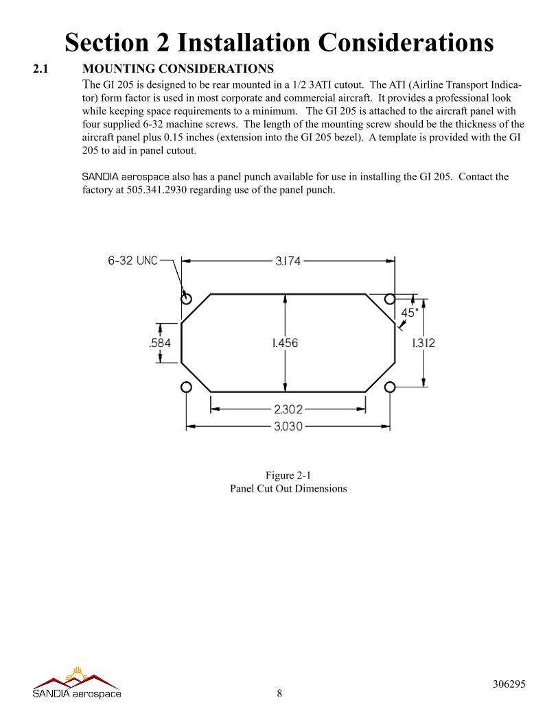
Section 2 Installation Considerations2.1 MOUNTING CONSIDERATIONS The GI 205 is designed to be rear mounted in a 1/2 3ATI cutout. The ATI (Airline Transport Indica-
tor) form factor is used in most corporate and commercial aircraft. It provides a professional look while keeping space requirements to a minimum. The GI 205 is attached to the aircraft panel with four supplied 6-32 machine screws. The length of the mounting screw should be the thickness of the aircraft panel plus 0.15 inches (extension into the GI 205 bezel). A template is provided with the GI 205 to aid in panel cutout.
SANDIA aerospace also has a panel punch available for use in installing the GI 205. Contact the factory at 505.341.2930 regarding use of the panel punch.
8
Figure 2-1Panel Cut Out Dimensions
306295
Section 3 Installation Procedures3.1 General
The GI 205 uses a 25 pin D-sub with crimp connectors. Failure to observe proper installation tech-niques could result in a failure of a connection and cause intermittent or non operation of the GI 205.
3.2 Equipment Required 3.2.1 Supplied GI 205 P/N 306273-00 (Garmin P/N 013-02121-00) 4 each 6-32 x 1/4” pan head screws for mounting to the instrument panel.3.2.2 Available Installation Kit P/N 306289-00 (Garmin P/N 013-02121-50) CONN, DSUB, RECP, 25 POS, W/CRIMP SKTS, P/N 305720 CLAMP, DSUB 25P SIZE, METAL, P/N 306294
9
3.3 Electrical ConsiderationsThe GI 205 operates on 11-32Vdc. Power can be supplied from the same breaker that is used for the Garmin Radar Altimeter or it can be powered through it’s own 1 Amp circuit breaker. If powered us-ing the Radar Altimeter breaker, the breaker size should be increased to accommodate the GI 205.
The GI 205 uses a single 25 pin D-Sub connector for all power and interface functions.
Power and ground wires are 20 AWG. All other wires are 22 AWG unless otherwise noted.
Installation to be in accordance with FAA AC 43.13-1B
3.4 Backshell AssemblyThe GI 205 connector kit includes a backshell with strain relief assembly. The strain relief gives the installer the ability to quickly terminate shields.
3.5 Post Installation ConfigurationIf the INHIBIT DECISION HEIGHT pin (P1-12) is connected to ground, the decision height selec-tor functions are removed from the display and only Radar Altimeter altitude and altitude alerts from the GRA are issued.
Allotherconfigurationsareperformedthroughthedisplayandknob.
Therearetwoconfigurationmenus.TheUserConfigurationMenusandthefullInstallationCon-figurationMenus.ToentertheInstallationConfigurationMenus,select1300ftDecisionHeight(or390Meters)andholdtheknobinformorethan5seconds.ToentertheUserConfigurationMenus,select a Decision Height other than 1300 feet and hold in the knob for more than 5 seconds.
306295
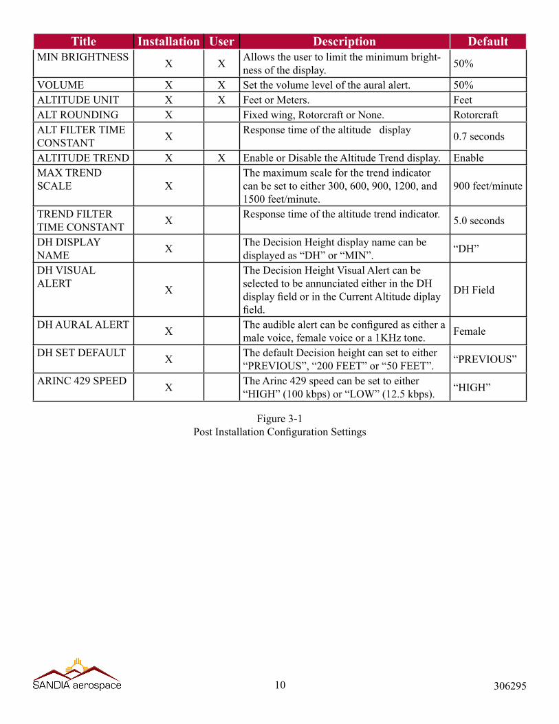
Title Installation User Description DefaultMIN BRIGHTNESS X X Allows the user to limit the minimum bright-
ness of the display. 50%
VOLUME X X Set the volume level of the aural alert. 50%ALTITUDE UNIT X X Feet or Meters. FeetALT ROUNDING X Fixed wing, Rotorcraft or None. RotorcraftALT FILTER TIME CONSTANT X Response time of the altitude display 0.7 seconds
ALTITUDE TREND X X Enable or Disable the Altitude Trend display. EnableMAX TREND SCALE X
The maximum scale for the trend indicator can be set to either 300, 600, 900, 1200, and 1500 feet/minute.
900 feet/minute
TREND FILTER TIME CONSTANT X Response time of the altitude trend indicator. 5.0 seconds
DH DISPLAY NAME X The Decision Height display name can be
displayed as “DH” or “MIN”. “DH”
DH VISUAL ALERT X
The Decision Height Visual Alert can be selected to be annunciated either in the DH displayfieldorintheCurrentAltitudediplayfield.
DH Field
DH AURAL ALERT X Theaudiblealertcanbeconfiguredaseitheramale voice, female voice or a 1KHz tone. Female
DH SET DEFAULT X The default Decision height can set to either “PREVIOUS”, “200 FEET” or “50 FEET”. “PREVIOUS”
ARINC 429 SPEED X The Arinc 429 speed can be set to either “HIGH” (100 kbps) or “LOW” (12.5 kbps). “HIGH”
10
Figure 3-1PostInstallationConfigurationSettings
306295
11
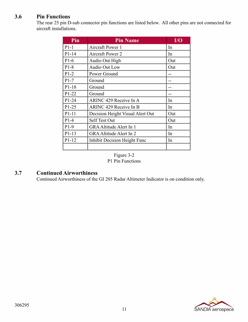
Pin Pin Name I/OP1-1 Aircraft Power 1 InP1-14 Aircraft Power 2 InP1-6 Audio Out High OutP1-8 Audio Out Low OutP1-2 Power Ground --P1-7 Ground --P1-18 Ground --P1-22 Ground --P1-24 ARINC 429 Receive In A InP1-25 ARINC 429 Receive In B InP1-11 Decision Height Visual Alert Out OutP1-4 Self Test Out OutP1-9 GRA Altitude Alert In 1 InP1-13 GRA Altitude Alert In 2 InP1-12 Inhibit Decision Height Func In
3.6 Pin FunctionsThe rear 25 pin D-sub connector pin functions are listed below. All other pins are not connected for aircraft installations.
3.7 Continued Airworthiness Continued Airworthiness of the GI 205 Radar Altimeter Indicator is on condition only.
Figure 3-2P1 Pin Functions
306295
12
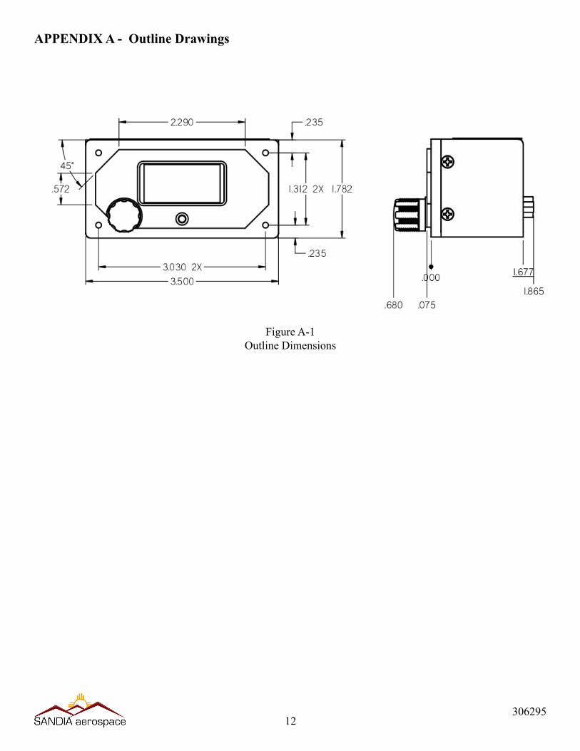
APPENDIX A - Outline Drawings
Figure A-1Outline Dimensions
306295
13
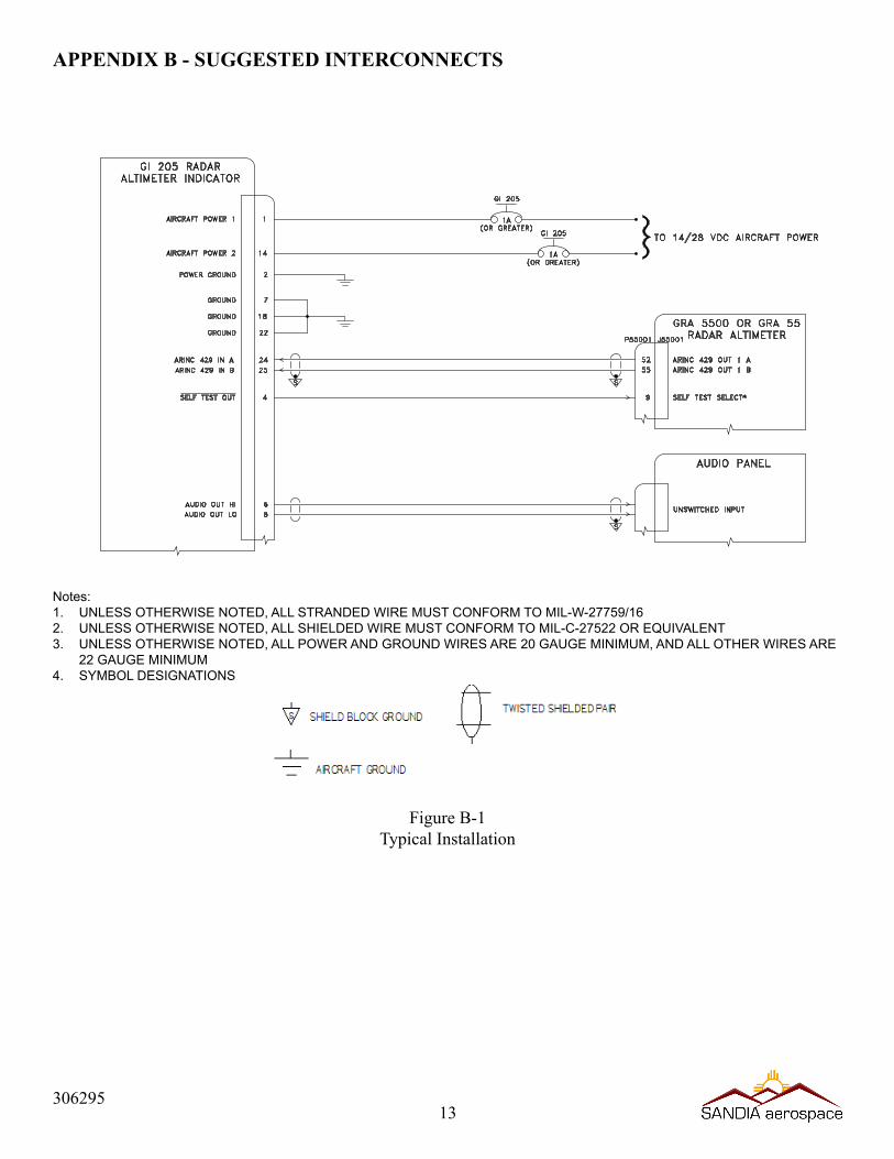
APPENDIX B - SUGGESTED INTERCONNECTS
Figure B-1Typical Installation
306295
GI 205 RADARALTIMETER INDICATOR
1AIRCRAFT POWER 1
14AIRCRAFT POWER 2
GI 205 INTERCONNECT EXAMPLE
GI 205
1A(OR GREATER)
GI 205
1A(OR GREATER)
}TO 14/28 VDC AIRCRAFT POWER
2POWER GROUND
S
24ARINC 429 IN A
25ARINC 429 IN B
GRA 5500 OR GRA 55RADAR ALTIMETER
ARINC 429 OUT 1 AARINC 429 OUT 1 B
5255
S
4SELF TEST OUT SELF TEST SELECT* 9
P55001 J55001
6
8
AUDIO PANEL
AUDIO OUT HI
AUDIO OUT LO
S
UNSWITCHED INPUT
18GROUND
7GROUND
22GROUND
Notes:1. UNLESS OTHERWISE NOTED, ALL STRANDED WIRE MUST CONFORM TO MIL-W-27759/162. UNLESS OTHERWISE NOTED, ALL SHIELDED WIRE MUST CONFORM TO MIL-C-27522 OR EQUIVALENT3. UNLESS OTHERWISE NOTED, ALL POWER AND GROUND WIRES ARE 20 GAUGE MINIMUM, AND ALL OTHER WIRES ARE
22 GAUGE MINIMUM4. SYMBOL DESIGNATIONS