Embed Size (px)
Citation preview
Manufactured by SJE Corporation, Ltd.
User’s Manual Operating and Maintenance Instructions
Model: OPTIMA DM Series
Distributor’s Contact:
Published by SJE Corporation, Ltd. Copyright © 2009 by SJE Corporation, Ltd.
San 225 Yelim-Li, Jeonggwan-Myeon,Gijang-Gun
Busan, Republic of Korea Tel +82 51-521-3200 Fax +82 51-521-3305
Website http://www.sjecorp.com E-mail [email protected]
All rights reserved. No part of this publication may be reproduced, stored in a retrieval system, or transmitted, in any form or by any means, electronic, mechanical, photocopying,
recording, or otherwise, without the prior permission of SJE Corporation, Ltd.
Printed in Republic of Korea

Table of Contents Introduction ----------------------------------------------------------------------------------------------------------------- 1
Intended Applications ---------------------------------------------------------------------------------------------------- 1
Safety Precautions ------------------------------------------------------------------------------------------------------- 1
Symbols Key --------------------------------------------------------------------------------------------------------------- 3
Specifications -------------------------------------------------------------------------------------------------------------- 4
Parts Description---------------------------------------------------------------------------------------------------------- 5
Pre-start Procedure ------------------------------------------------------------------------------------------------------ 9
Automatic Feedwater System (Standard for Optima-DMF) ---------------------------------------------------- 10
Starting the Optima for the First Time ------------------------------------------------------------------------------ 11
Standard Start-Up Procedure ----------------------------------------------------------------------------------------- 12
Moisture Control --------------------------------------------------------------------------------------------------------- 13
Pause Operations ------------------------------------------------------------------------------------------------------- 14
Shutdown Procedure --------------------------------------------------------------------------------------------------- 14
Freeze Prevention ------------------------------------------------------------------------------------------------------- 15
Maintenance -------------------------------------------------------------------------------------------------------------- 17
Safety Features ---------------------------------------------------------------------------------------------------------- 23
Troubleshooting Guide ------------------------------------------------------------------------------------------------- 25

1
Introduction The Optima represents the future of environmentally friendly and effective cleaning. Safe, durable and easy to use, the Optima will support your cleaning operations for many years to come.
Intended Applications The Optima Steamer is designed exclusively for cleaning vehicles, machines and general surfaces
capable of handling steam jet pressure of up to 8 bar (116psi) and temperatures reaching 85℃-
120℃ (185℉-248℉). The Optima Steamer has numerous applications; clean machinery, vehicle exteriors, interiors, engine compartments, windows, wheel wells, sterilize, deodorize, remove weeds and much more.
Safety Precautions Before operating the Optima for the first time, read the manual completely. The manufacturer and distributors are not liable for mechanical troubles, property damage, or personal injury caused by the operator(s) unfamiliarity with the manual’s instructions.
• With regards to the boiler, use only water and the manufacturer’s recommended boiler
cleansing solution. Do not put any other chemicals or detergents into the water tank or boiler. • Do not use distilled or de-ionized water. • Use only clean tap water. “Soft” water is recommended. • Use only clean diesel. • Provide adequate electrical specifications the machine requires.
• Make sure that all the switches on the machine are off before plugging the machine into an electrical outlet.
• If an extension cord is used, insure that it is of watertight construction and of proper diameter based on the cord length and required electrical specifications.
• Turn off the Power switch when refilling the water or the fuel tank. • Unplug the Optima from its power source and allow the Optima to cool before carrying out
maintenance.
• Use only hoses, fittings and couplings recommended by the manufacturer. • Use only spare parts approved by the manufacturer. • Use and store the Optima on a leveled surface.
2
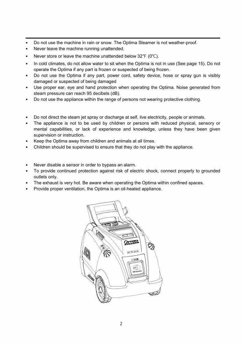
• Do not use the machine in rain or snow. The Optima Steamer is not weather-proof. • Never leave the machine running unattended.
• Never store or leave the machine unattended below 32℉ (0℃). • In cold climates, do not allow water to sit when the Optima is not in use (See page 15). Do not
operate the Optima if any part is frozen or suspected of being frozen. • Do not use the Optima if any part, power cord, safety device, hose or spray gun is visibly
damaged or suspected of being damaged • Use proper ear, eye and hand protection when operating the Optima. Noise generated from
steam pressure can reach 95 decibels (dB). • Do not use the appliance within the range of persons not wearing protective clothing.
• Do not direct the steam jet spray or discharge at self, live electricity, people or animals. • The appliance is not to be used by children or persons with reduced physical, sensory or
mental capabilities, or lack of experience and knowledge, unless they have been given supervision or instruction.
• Keep the Optima away from children and animals at all times. • Children should be supervised to ensure that they do not play with the appliance.
• Never disable a sensor in order to bypass an alarm. • To provide continued protection against risk of electric shock, connect properly to grounded
outlets only. • The exhaust is very hot. Be aware when operating the Optima within confined spaces. • Provide proper ventilation, the Optima is an oil-heated appliance.
3
TS
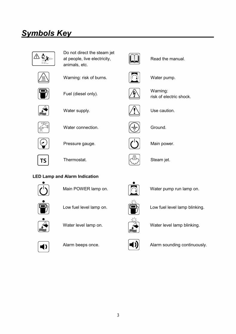
Symbols Key
LED Lamp and Alarm Indication
Main POWER lamp on.
Water pump run lamp on.
Low fuel level lamp on.
Low fuel level lamp blinking.
Water level lamp on.
Water level lamp blinking.
Alarm beeps once.
Alarm sounding continuously.
Do not direct the steam jet at people, live electricity, animals, etc.
Read the manual.
Warning: risk of burns.
Water pump.
Fuel (diesel only).
Warning: risk of electric shock.
Water supply.
Use caution.
Water connection.
Ground.
Pressure gauge.
Main power.
Thermostat.
Steam jet.

4
Specifications
Model Optima DM/DMF Optima DS
Working Pressure 8 bar / 116 psi (Max. 10 bar / 145 psi)
Working Temperature < 100℃ / 212℉
Boiler Temperature 178℃ / 352℉ (Max. 200℃ / 392℉)
Preheating Time 2 ~ 3 minutes
Rated Electric Power 180 (280 Max.) Watts
Voltage / Hertz 110~120V 50/60Hz, 220~240V 50/60Hz
(Custom configuration available)
Water Tank Capacity 20 ℓ / 5.3 gals N.A.
Water Consumption Rate (Max) Max.600 cc/min (0.165 gpm)
Diesel Tank Capacity 20 ℓ / 5.3 gals 17 ℓ / 4.5 gals
Diesel Consumption Rate 2.0 ltr/hr ( 0.52 gph) 2.0 ltr/hr ( 0.52 gph)
Net Weight 83 kgs / 184 lbs 91 kgs / 201 lbs
Net Dimensions 109 x 70 x H90 cm (43” x 28.3” x H35.4”)
78 x 50 x H76 cm (30.7” x 19.7” x H30”)
Note! * To ensure safety and machine effectiveness, do not alter the preset steam pressure and
temperature settings. * Moisture content in the steam can be adjusted by the moisture control valve. (See page 13)
Water Quality Matters! Water quality can greatly affect the Optima’s life span and performance. It is important to use clean tap water or soft water. Daily use of water treatment and regular scale removal will help ensure efficient operations (see “Maintenance” for more information), and using a water softener is also recommended. Do not use distilled or de-ionized water. Do not put any other chemicals or detergents into the water tank or boiler. The water temperature should be above 5℃ (40℉).

5
Parts Description Left side – Top -Back
Fig. 1
1. Boiler flue 2. Throttle door 3. Tank cap 4. Water tank 5. Y-strainer 6. Drain valve 7. Non-return valve 8. Drain valve 9. Plug for Coupling
10. Moisture control valve 11. Steam outlet 12. Steam outlet valve 13. Warning stickers 14. Operating instructions 15. Name plate 16. Handle 17. Control panel

6
Front without Cover
Fig. 2
1. Boiler 2. Tank cap 3. Fuel suction line 4. Fuel filter 5. Fuel tank 6. Float switch
7. Tank drain cap 8. Low water probe sensor 9. High water probe sensor 10. Water tank 11. Water filter 12. Fuel return line
7
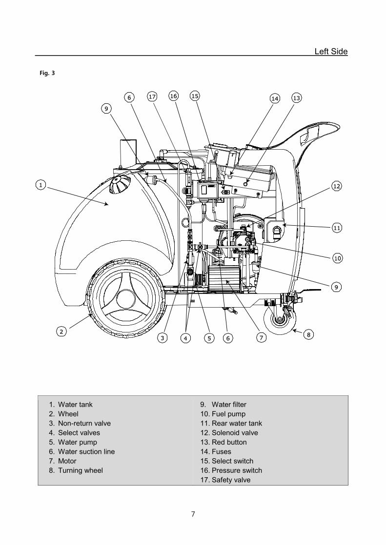
Left Side
Fig. 3
1. Water tank 2. Wheel 3. Non-return valve 4. Select valves 5. Water pump 6. Water suction line 7. Motor 8. Turning wheel
9. Water filter 10. Fuel pump 11. Rear water tank 12. Solenoid valve 13. Red button 14. Fuses 15. Select switch 16. Pressure switch 17. Safety valve
8
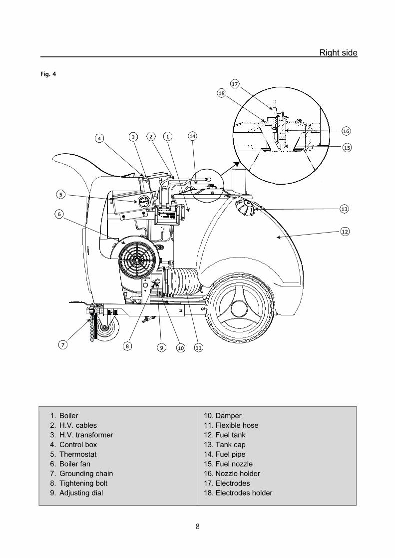
Right side
Fig. 4
1. Boiler 2. H.V. cables 3. H.V. transformer 4. Control box 5. Thermostat 6. Boiler fan 7. Grounding chain 8. Tightening bolt 9. Adjusting dial
10. Damper 11. Flexible hose 12. Fuel tank 13. Tank cap 14. Fuel pipe 15. Fuel nozzle 16. Nozzle holder 17. Electrodes 18. Electrodes holder

9
Pre-start Procedure Steps: 1. Connect the steam hose and gun to the steam outlet. Insure a tight connection (use wrench)
(Fig. 5). 2. Fill the water tank with tap water (Fig. 6). Add recommended dosage of water treatment to the
water tank. Do not use distilled or de-ionized water. 3. Fill the fuel tank with diesel (Fig. 8). 4. Plug the machine into an electrical outlet with all the switches on the machine off. If an extension cord is used, the plug and the socket must be of watertight construction. Inadequate extension cords can be dangerous.
Fig. 5
Fig. 6
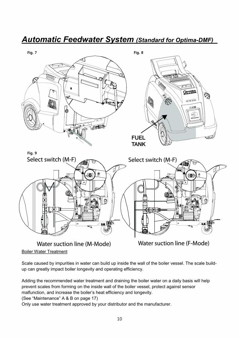
Automatic feedwater device( Standard for Optima- DMF) When water is being supplied by a hose in the stationary position, open the throttle door and change the select switch and the water suction valves to “F” from “M” simultaneously (Fig. 7 & 9).
Through the throttle door, add a daily dose of water treatment to the rear water tank. Connect a hose to the hose fitting located at the bottom of the rear water tank (Fig. 7).
10
Automatic Feedwater System (Standard for Optima-DMF) Fig. 7
Fig. 8
Fig. 9
Boiler Water Treatment Scale caused by impurities in water can build up inside the wall of the boiler vessel. The scale build-up can greatly impact boiler longevity and operating efficiency. Adding the recommended water treatment and draining the boiler water on a daily basis will help prevent scales from forming on the inside wall of the boiler vessel, protect against sensor malfunction, and increase the boiler’s heat efficiency and longevity. (See “Maintenance” A & B on page 17) Only use water treatment approved by your distributor and the manufacturer.
11
Starting the Optima for the First Time
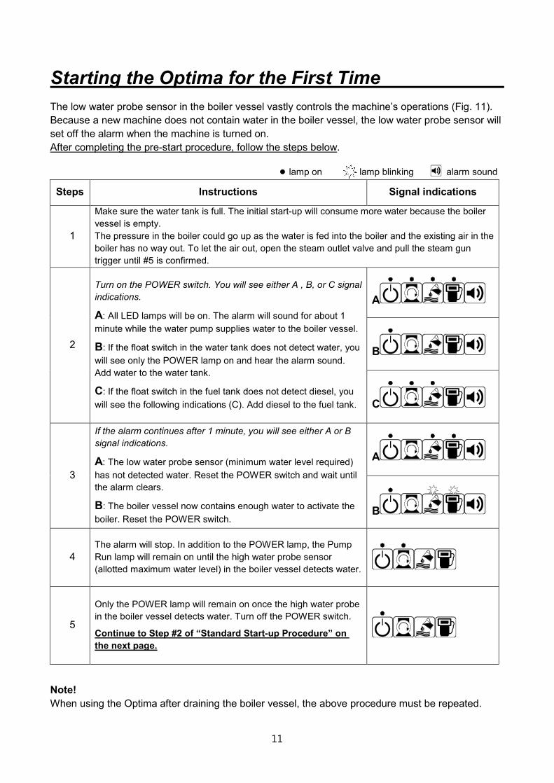
The low water probe sensor in the boiler vessel vastly controls the machine’s operations (Fig. 11). Because a new machine does not contain water in the boiler vessel, the low water probe sensor will set off the alarm when the machine is turned on. After completing the pre-start procedure, follow the steps below.
● lamp on lamp blinking alarm sound
Steps Instructions Signal indications
1
Make sure the water tank is full. The initial start-up will consume more water because the boiler vessel is empty. The pressure in the boiler could go up as the water is fed into the boiler and the existing air in the boiler has no way out. To let the air out, open the steam outlet valve and pull the steam gun trigger until #5 is confirmed.
2
Turn on the POWER switch. You will see either A , B, or C signal indications.
A: All LED lamps will be on. The alarm will sound for about 1 minute while the water pump supplies water to the boiler vessel.
B: If the float switch in the water tank does not detect water, you will see only the POWER lamp on and hear the alarm sound. Add water to the water tank.
C: If the float switch in the fuel tank does not detect diesel, you will see the following indications (C). Add diesel to the fuel tank.
A
B
C
3
If the alarm continues after 1 minute, you will see either A or B signal indications.
A: The low water probe sensor (minimum water level required) has not detected water. Reset the POWER switch and wait until the alarm clears.
B: The boiler vessel now contains enough water to activate the boiler. Reset the POWER switch.
A
B
4 The alarm will stop. In addition to the POWER lamp, the Pump Run lamp will remain on until the high water probe sensor (allotted maximum water level) in the boiler vessel detects water.
5
Only the POWER lamp will remain on once the high water probe in the boiler vessel detects water. Turn off the POWER switch.
Continue to Step #2 of “Standard Start-up Procedure” on the next page.
Note! When using the Optima after draining the boiler vessel, the above procedure must be repeated.
12
Standard Start-Up Procedure
Fig. 10
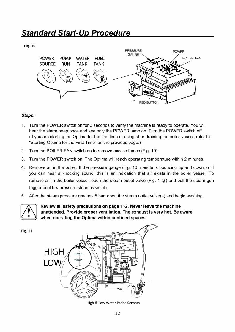
Steps: 1. Turn the POWER switch on for 3 seconds to verify the machine is ready to operate. You will
hear the alarm beep once and see only the POWER lamp on. Turn the POWER switch off. (If you are starting the Optima for the first time or using after draining the boiler vessel, refer to “Starting Optima for the First Time” on the previous page.)
2. Turn the BOILER FAN switch on to remove excess fumes (Fig. 10).
3. Turn the POWER switch on. The Optima will reach operating temperature within 2 minutes.
4. Remove air in the boiler. If the pressure gauge (Fig. 10) needle is bouncing up and down, or if you can hear a knocking sound, this is an indication that air exists in the boiler vessel. To
remove air in the boiler vessel, open the steam outlet valve (Fig. 1-⑫) and pull the steam gun trigger until low pressure steam is visible.
5. After the steam pressure reaches 8 bar, open the steam outlet valve(s) and begin washing.
Review all safety precautions on page 1~2. Never leave the machine unattended. Provide proper ventilation. The exhaust is very hot. Be aware when operating the Optima within confined spaces.
Fig. 11
High & Low Water Probe Sensors
13
Moisture Control
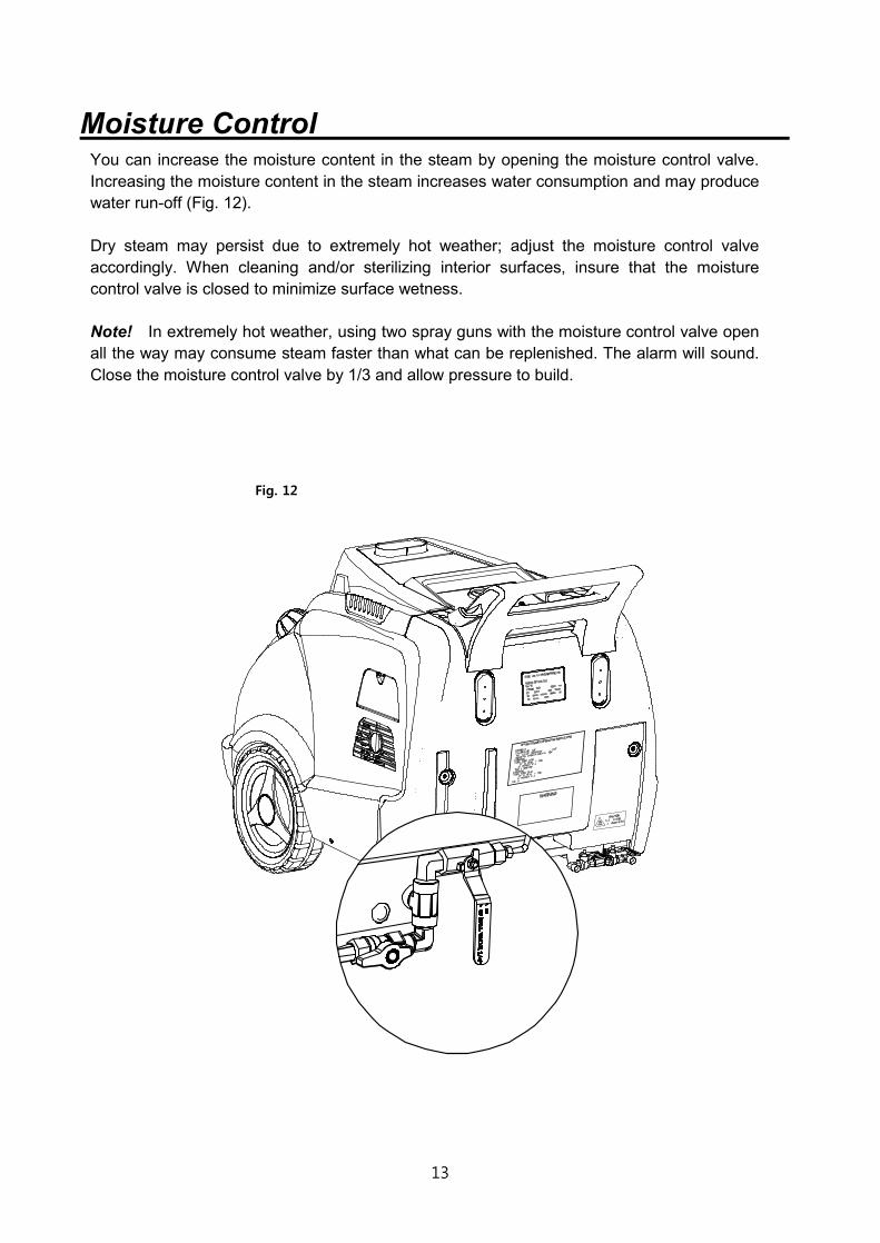
You can increase the moisture content in the steam by opening the moisture control valve. Increasing the moisture content in the steam increases water consumption and may produce water run-off (Fig. 12). Dry steam may persist due to extremely hot weather; adjust the moisture control valve accordingly. When cleaning and/or sterilizing interior surfaces, insure that the moisture control valve is closed to minimize surface wetness. Note! In extremely hot weather, using two spray guns with the moisture control valve open all the way may consume steam faster than what can be replenished. The alarm will sound. Close the moisture control valve by 1/3 and allow pressure to build.
Fig. 12

14
Pause Operations Steps: 1. Turn the POWER switch off.
2. To remove excess fumes, let the boiler fan run for 1 minute. Turn the BOILER FAN switch off.
3. Close the steam outlet valve and pull the steam gun trigger to release any remaining steam in the hose. This will prevent the release of water (cooled steam) and increase the life span of the steam hose and gun.
Note! When refilling the water or the fuel tank, turn off the POWER switch. The BOILER FAN switch can remain on. After refilling the water or fuel tank, turn the POWER switch back on. Resume operation.
Shutdown Procedure Steps: 1. Turn off the POWER switch.
2. Use up the existing steam in the boiler vessel until the pressure drops to 2 bar.
3. Turn the BOILER FAN switch off.
4. Drain the water in the boiler by opening the boiler drain valve (Fig. 1-⑧).
If the water from the boiler vessel is milky, drain all remaining water of the boiler vessel by
opening the Y-strainer drain valve (Fig. 1-⑥).
5. Close the steam outlet valve and pull the spray gun trigger to release the remaining steam in the hose. This will prevent the release of water (cooled steam) and increase the life span of the steam hose and spray gun.
6. In cold climates, additional steps are required to prevent damages.
(See "Freeze Prevention" on page 15~16).
Tips! Extend the life span of the Optima 1. Use clean tap or soft water. 2. Use water treatment daily. 3. Always remove air from the boiler vessel before use. 4. Always remove steam from hoses, spray guns, and the boiler vessel after use. 5. Store the Optima at room temperature 6. Remove hardened scale from the boiler regularly by performing de-scaling (page 19~21). 7. Remove softened sludge from the boiler regularly (page 17).
15
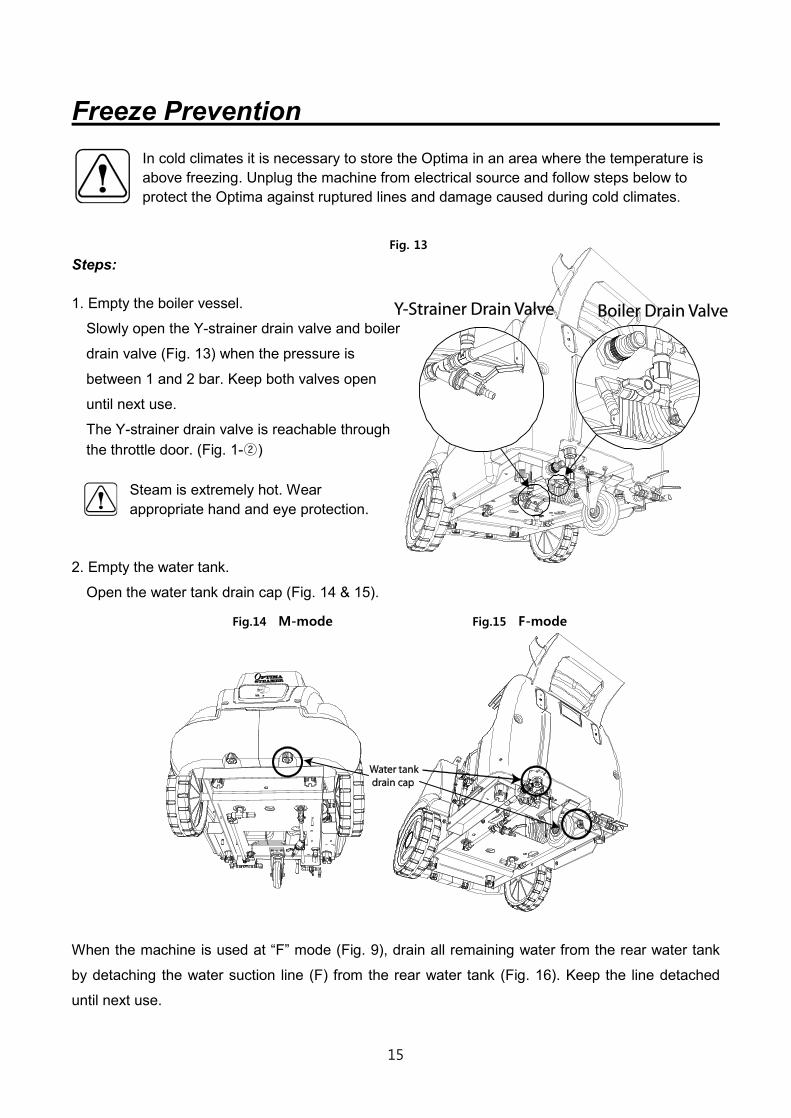
Freeze Prevention In cold climates it is necessary to store the Optima in an area where the temperature is above freezing. Unplug the machine from electrical source and follow steps below to protect the Optima against ruptured lines and damage caused during cold climates.
Steps: 1. Empty the boiler vessel.
Slowly open the Y-strainer drain valve and boiler
drain valve (Fig. 13) when the pressure is
between 1 and 2 bar. Keep both valves open
until next use.
The Y-strainer drain valve is reachable through the throttle door. (Fig. 1-②)
Steam is extremely hot. Wear appropriate hand and eye protection.
2. Empty the water tank.
Open the water tank drain cap (Fig. 14 & 15).
Fig.14 M-mode Fig.15 F-mode
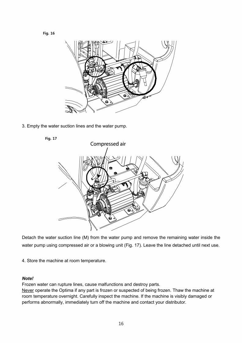
When the machine is used at “F” mode (Fig. 9), drain all remaining water from the rear water tank
by detaching the water suction line (F) from the rear water tank (Fig. 16). Keep the line detached
until next use.
Fig. 13
16
3. Empty the water suction lines and the water pump.
Detach the water suction line (M) from the water pump and remove the remaining water inside the
water pump using compressed air or a blowing unit (Fig. 17). Leave the line detached until next use.
4. Store the machine at room temperature. Note! Frozen water can rupture lines, cause malfunctions and destroy parts. Never operate the Optima if any part is frozen or suspected of being frozen. Thaw the machine at room temperature overnight. Carefully inspect the machine. If the machine is visibly damaged or performs abnormally, immediately turn off the machine and contact your distributor.
Fig. 16
Fig. 17
17
Maintenance
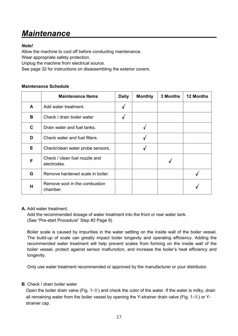
Note! Allow the machine to cool off before conducting maintenance. Wear appropriate safety protection. Unplug the machine from electrical source. See page 32 for instructions on disassembling the exterior covers. Maintenance Schedule
Maintenance Items Daily Monthly 3 Months 12 Months
A Add water treatment.
B Check / drain boiler water
C Drain water and fuel tanks.
D Check water and fuel filters.
E Check/clean water probe sensors.
F Check / clean fuel nozzle and electrodes.
G Remove hardened scale in boiler.
H Remove soot in the combustion chamber.
A. Add water treatment.
Add the recommended dosage of water treatment into the front or rear water tank. (See “Pre-start Procedure” Step #2 Page 9) Boiler scale is caused by impurities in the water settling on the inside wall of the boiler vessel. The build-up of scale can greatly impact boiler longevity and operating efficiency. Adding the recommended water treatment will help prevent scales from forming on the inside wall of the boiler vessel, protect against sensor malfunction, and increase the boiler’s heat efficiency and longevity. Only use water treatment recommended or approved by the manufacturer or your distributor.
B. Check / drain boiler water
Open the boiler drain valve (Fig. 1-⑧) and check the color of the water. If the water is milky, drain all remaining water from the boiler vessel by opening the Y-strainer drain valve (Fig. 1-⑥) or Y-strainer cap.

18
C. Drain water and fuel tanks. Contaminates can settle to the bottom of both the fuel and water tanks. Remove the drain caps from both tanks (Fig. 18).
D. Check the water and fuel filters routinely and replace if needed (Fig. 19).
Fig. 18 Fig. 19
E. Check/clean water probe sensors.
The Optima has two water probe sensors (low and high) (Fig. 11). Mineral build-up and scale on the water probe sensors can affect sensor accuracy.
What you will need: screw driver (+), 14mm deep socket wrench or double wrench (Do not use a torque wrench or power tools), sandpaper, and Teflon tape.
Steps: 1. Unplug the machine and let the steam pressure drop to the bottom. 2. Drain the boiler vessel by opening the boiler drain valve (Fig. 1-⑧). 3. Remove the front cover (See page 32) and disconnect the sensors from wiring. 4. Remove the sensors from the boiler using 14mm deep socket wrench. 5. Using sandpaper, scrub the sensors clean. Replace them if necessary. 6. Wrap the threads of the sensors with Teflon tape and reassemble the sensors using the tool.
Testing the low water probe sensor (RED BUTTON) As one of the machine’s safety features, the low water probe sensor in the boiler vessel vastly controls the machine’s operations. If the sensor does not detect water, the machine’s CPU shuts off the boiler and sets off the alarm. To confirm the low water probe sensor is not functioning due to hardened scale, a
malfunction, or water temperature below 5℃, turn on the POWER switch while the red button is pushed down (Fig. 20). Do not push the button for longer than 10 seconds when the POWER switch is on. If the alarm stops, this means the sensor cannot detect water despite its presence in the boiler vessel. If this occurs, the high and low water probe sensors need to be cleaned or replaced, or the
water temperature should be increased above 5℃.
Fig. 20
19
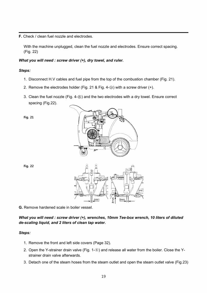
F. Check / clean fuel nozzle and electrodes.
With the machine unplugged, clean the fuel nozzle and electrodes. Ensure correct spacing. (Fig. 22)
What you will need : screw driver (+), dry towel, and ruler. Steps:
1. Disconnect H.V cables and fuel pipe from the top of the combustion chamber (Fig. 21).
2. Remove the electrodes holder (Fig. 21 & Fig. 4-○18 ) with a screw driver (+).
3. Clean the fuel nozzle (Fig. 4-⑮) and the two electrodes with a dry towel. Ensure correct spacing (Fig.22).
Fig. 21
Fig. 22
G. Remove hardened scale in boiler vessel. What you will need : screw driver (+), wrenches, 10mm Tee-box wrench, 10 liters of diluted de-scaling liquid, and 2 liters of clean tap water. Steps:
1. Remove the front and left side covers (Page 32).
2. Open the Y-strainer drain valve (Fig. 1-⑥) and release all water from the boiler. Close the Y-strainer drain valve afterwards.
3. Detach one of the steam hoses from the steam outlet and open the steam outlet valve (Fig.23)
20
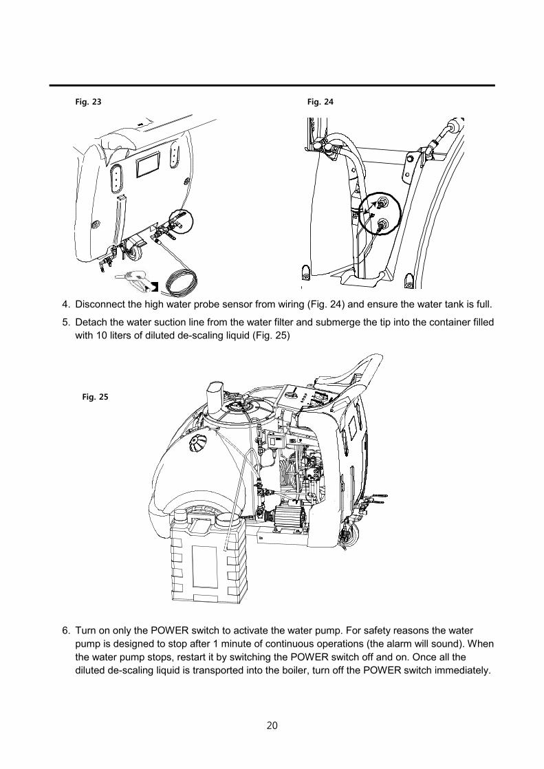
Fig. 23 Fig. 24
4. Disconnect the high water probe sensor from wiring (Fig. 24) and ensure the water tank is full.
5. Detach the water suction line from the water filter and submerge the tip into the container filled with 10 liters of diluted de-scaling liquid (Fig. 25)
Fig. 25
6. Turn on only the POWER switch to activate the water pump. For safety reasons the water pump is designed to stop after 1 minute of continuous operations (the alarm will sound). When the water pump stops, restart it by switching the POWER switch off and on. Once all the diluted de-scaling liquid is transported into the boiler, turn off the POWER switch immediately.
21
7. Submerge the tip of the water suction line into the container filled with 2 liters of clean tap water and turn on only the POWER switch to run the water pump. Once water starts coming out of the steam outlet, turn off the POWER switch and close the steam outlet valve. The clean tap water is to wash out the water pump.
8. Let the machine sit for the time instructed on the de-scaling liquid label. Do not exceed the recommended time to avoid boiler damage.
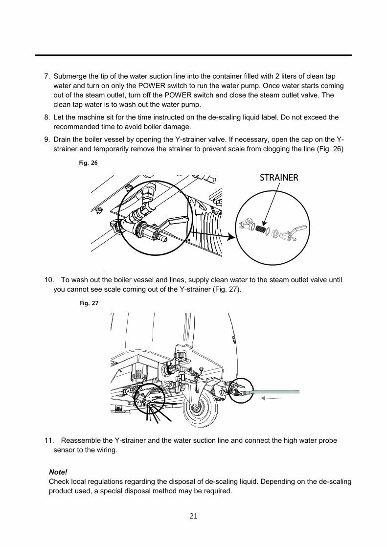
9. Drain the boiler vessel by opening the Y-strainer valve. If necessary, open the cap on the Y-strainer and temporarily remove the strainer to prevent scale from clogging the line (Fig. 26)
Fig. 26
10. To wash out the boiler vessel and lines, supply clean water to the steam outlet valve until you cannot see scale coming out of the Y-strainer (Fig. 27).
Fig. 27
11. Reassemble the Y-strainer and the water suction line and connect the high water probe
sensor to the wiring.
Note! Check local regulations regarding the disposal of de-scaling liquid. Depending on the de-scaling product used, a special disposal method may be required.
22
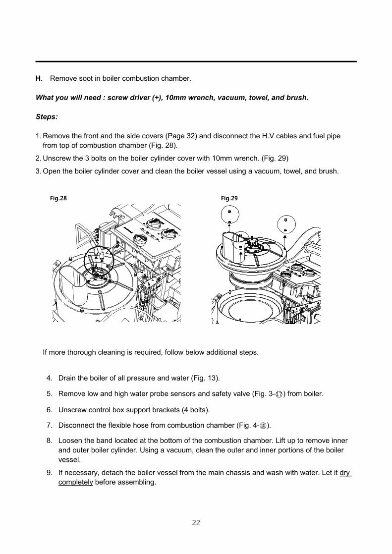
H. Remove soot in boiler combustion chamber. What you will need : screw driver (+), 10mm wrench, vacuum, towel, and brush. Steps: 1. Remove the front and the side covers (Page 32) and disconnect the H.V cables and fuel pipe
from top of combustion chamber (Fig. 28).
2. Unscrew the 3 bolts on the boiler cylinder cover with 10mm wrench. (Fig. 29)
3. Open the boiler cylinder cover and clean the boiler vessel using a vacuum, towel, and brush.
Fig.28 Fig.29
If more thorough cleaning is required, follow below additional steps.
4. Drain the boiler of all pressure and water (Fig. 13).
5. Remove low and high water probe sensors and safety valve (Fig. 3-○17 ) from boiler.
6. Unscrew control box support brackets (4 bolts).
7. Disconnect the flexible hose from combustion chamber (Fig. 4-⑩).
8. Loosen the band located at the bottom of the combustion chamber. Lift up to remove inner and outer boiler cylinder. Using a vacuum, clean the outer and inner portions of the boiler vessel.
9. If necessary, detach the boiler vessel from the main chassis and wash with water. Let it dry completely before assembling.
23
Safety Features
The Optima was designed with operator safety in mind. There are multiple safety features that protect both the operator(s) and the Optima. Understanding the Optima’s safety features will enhance the user experience and assist you when troubleshooting.
The Optima’s Main Safety Features:
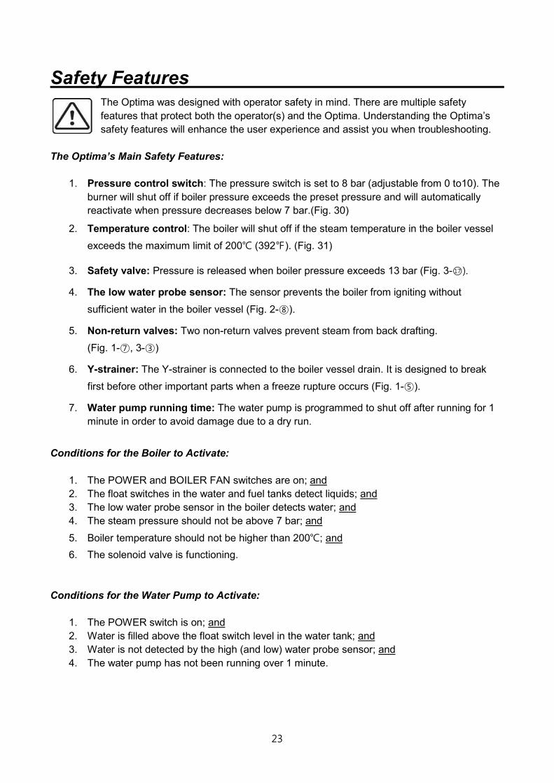
1. Pressure control switch: The pressure switch is set to 8 bar (adjustable from 0 to10). The burner will shut off if boiler pressure exceeds the preset pressure and will automatically reactivate when pressure decreases below 7 bar.(Fig. 30)
2. Temperature control: The boiler will shut off if the steam temperature in the boiler vessel
exceeds the maximum limit of 200℃ (392℉). (Fig. 31)
3. Safety valve: Pressure is released when boiler pressure exceeds 13 bar (Fig. 3-○17 ).
4. The low water probe sensor: The sensor prevents the boiler from igniting without
sufficient water in the boiler vessel (Fig. 2-⑧).
5. Non-return valves: Two non-return valves prevent steam from back drafting.
(Fig. 1-⑦, 3-③)
6. Y-strainer: The Y-strainer is connected to the boiler vessel drain. It is designed to break
first before other important parts when a freeze rupture occurs (Fig. 1-⑤).
7. Water pump running time: The water pump is programmed to shut off after running for 1 minute in order to avoid damage due to a dry run.
Conditions for the Boiler to Activate:
1. The POWER and BOILER FAN switches are on; and 2. The float switches in the water and fuel tanks detect liquids; and 3. The low water probe sensor in the boiler detects water; and 4. The steam pressure should not be above 7 bar; and
5. Boiler temperature should not be higher than 200℃; and 6. The solenoid valve is functioning.
Conditions for the Water Pump to Activate:
1. The POWER switch is on; and 2. Water is filled above the float switch level in the water tank; and 3. Water is not detected by the high (and low) water probe sensor; and 4. The water pump has not been running over 1 minute.

24
Note!
Pressure Increase above 8 bar Generally speaking, unexpected high pressure is generated due to compressed steam or water in the boiler vessel. When steam pressure gauge indicates above 8 bar, you must confirm the cause and take steps necessary before operating the machine again.
Steps 1. Check if the boiler is activated(on)
The first step to take is to verify the origin of high pressure. To do so, check if the boiler is activated (on) or not. If the boiler is activated, you will see a flame inside the boiler chamber and feel warm air coming out from the flue ( Do not put hands directly above the boiler flue.)
2. (a) The boiler is on. Cause and Remedy Turn off the POWER switch. The pressure gauge or the steam pressure switch is likely to be out of order à Contact your distributor (See “Troubleshooting Guide” reference No. 12).
(b) The boiler is off Cause and Remedy Release internal pressure by opening the steam outlet valves and pulling steam gun trigger(s). While the low probe water sensor is functioning, the high probe water sensor does not sense water even when the water is filled above the high water probe sensor level. In this case, water will continue to be supplied to the boiler vessel, and the pressure will increase due to increased water volume (amount) in the confined boiler vessel space. à Clean the high level prove sensor or replace if necessary (See “Troubleshooting Guide” reference No. 11).
Fig. 30 Fig. 31

25
Troubleshooting Guide When a malfunction occurs, refer to the troubleshooting guide below. If the problem persists, please contact your local distributor and report the problem by referring to the reference number on the left hand side. See page 32 for instructions on disassembling. LED Lamps Indication
Main POWER lamp on.
Water pump run lamp on.
Low water level lamp blinking.
Low water level lamp on.
Low fuel level lamp on.
Low fuel level lamp blinking.
Alarm beeps once. Alarm continuously beeping.
Continuous pressure increase over 8 bar. Continuous pressure decrease.
No. Lamps & Alarm Indications
Description, Cause
Remedy
1
No lamps on and no alarm sound when turning on the POWER switch due to;
1) No power supply 2) Blown fuse (F1)
1) Check your electrical power source.
2) Replace the fuse (F1). (Fig. 3-⑭)
2
The POWER switch is turned on. The POWER lamp is on and the alarm beeps once.
This is a normal indication that occurs when the POWER switch is on.
26
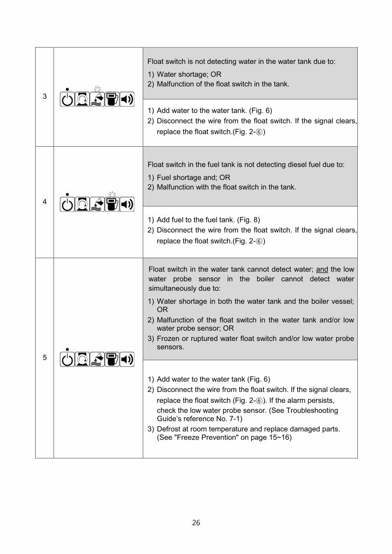
3
Float switch is not detecting water in the water tank due to:
1) Water shortage; OR 2) Malfunction of the float switch in the tank.
1) Add water to the water tank. (Fig. 6) 2) Disconnect the wire from the float switch. If the signal clears,
replace the float switch.(Fig. 2-⑥)
4
Float switch in the fuel tank is not detecting diesel fuel due to:
1) Fuel shortage and; OR 2) Malfunction with the float switch in the tank.
1) Add fuel to the fuel tank. (Fig. 8) 2) Disconnect the wire from the float switch. If the signal clears,
replace the float switch.(Fig. 2-⑥)
5
Float switch in the water tank cannot detect water; and the low water probe sensor in the boiler cannot detect water simultaneously due to:
1) Water shortage in both the water tank and the boiler vessel; OR
2) Malfunction of the float switch in the water tank and/or low water probe sensor; OR
3) Frozen or ruptured water float switch and/or low water probe sensors.
1) Add water to the water tank (Fig. 6) 2) Disconnect the wire from the float switch. If the signal clears,
replace the float switch (Fig. 2-⑥). If the alarm persists, check the low water probe sensor. (See Troubleshooting Guide’s reference No. 7-1)
3) Defrost at room temperature and replace damaged parts. (See "Freeze Prevention" on page 15~16)
27
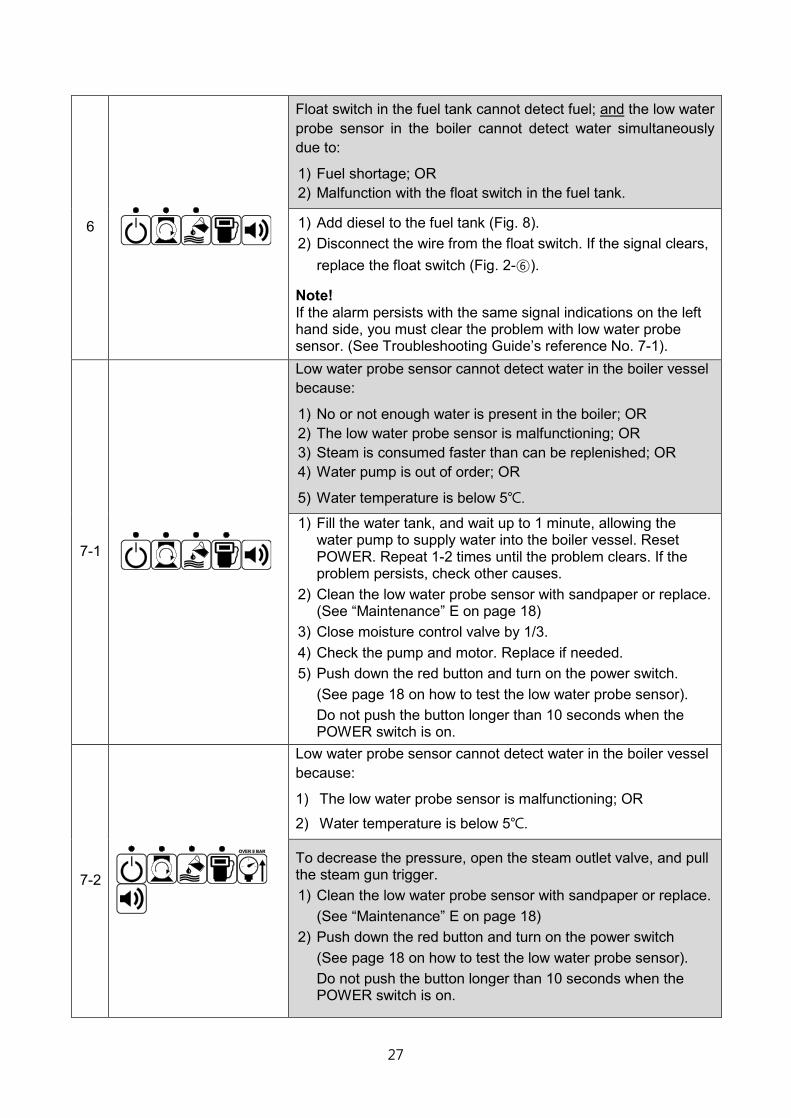
6
Float switch in the fuel tank cannot detect fuel; and the low water probe sensor in the boiler cannot detect water simultaneously due to:
1) Fuel shortage; OR 2) Malfunction with the float switch in the fuel tank.
1) Add diesel to the fuel tank (Fig. 8). 2) Disconnect the wire from the float switch. If the signal clears,
replace the float switch (Fig. 2-⑥).
Note! If the alarm persists with the same signal indications on the left hand side, you must clear the problem with low water probe sensor. (See Troubleshooting Guide’s reference No. 7-1).
7-1
Low water probe sensor cannot detect water in the boiler vessel because:
1) No or not enough water is present in the boiler; OR 2) The low water probe sensor is malfunctioning; OR 3) Steam is consumed faster than can be replenished; OR 4) Water pump is out of order; OR
5) Water temperature is below 5℃.
1) Fill the water tank, and wait up to 1 minute, allowing the water pump to supply water into the boiler vessel. Reset POWER. Repeat 1-2 times until the problem clears. If the problem persists, check other causes.
2) Clean the low water probe sensor with sandpaper or replace. (See “Maintenance” E on page 18)
3) Close moisture control valve by 1/3. 4) Check the pump and motor. Replace if needed. 5) Push down the red button and turn on the power switch.
(See page 18 on how to test the low water probe sensor). Do not push the button longer than 10 seconds when the POWER switch is on.
7-2
Low water probe sensor cannot detect water in the boiler vessel because:
1) The low water probe sensor is malfunctioning; OR
2) Water temperature is below 5℃.
To decrease the pressure, open the steam outlet valve, and pull the steam gun trigger. 1) Clean the low water probe sensor with sandpaper or replace.
(See “Maintenance” E on page 18) 2) Push down the red button and turn on the power switch
(See page 18 on how to test the low water probe sensor). Do not push the button longer than 10 seconds when the POWER switch is on.

28
8
Water pump runs over the running time limit of 1 minute for the reason that the low water probe sensor cannot detect water in the boiler vessel because:
1) Not enough water is being supplied to the boiler vessel; OR 2) Low water probe sensor cannot detect water despite the
presence of water in the boiler vessel; OR 3) Water pump is out of order.
1) Reset the water pump by switching the POWER switch off and on again. The alarm will clear once water reaches the low water probe sensor.
2) Clean the low water probe sensor with sandpaper or replace (See “Maintenance” E on page 18).
3) Check if the water pump and motor are functioning. If no water movement is visible in the water suction lines and filter, contact your distributor (Fig. 3).
9
Water pump ran over the running time limit of 1 minute for the reason that the high water probe sensor cannot detect water in the boiler vessel because:
1) Not enough water is being supplied to the boiler vessel; OR 2) High water probe sensor cannot detect water despite the
presence of water in the boiler; OR 3) Water pump is out of order.
1) Reset the water pump by switching the POWER switch off and on again. The alarm will clear once water reaches the high water probe sensor.
2) Clean the high water probe sensor with sandpaper or replace.
3) Check if the water pump and motor are functioning. If no water movement is visible in the water suction lines and filter, contact your distributor.
Note! If the high water probe sensor cannot detect the presence of water, water will continue to be supplied to the boiler vessel and cause an increase in pressure. When the water pressure
reaches 13 bar, the safety valve (Fig. 3-○17 ) located outside the
boiler will discharge excess pressure and water. Clean or replace the high water probe sensor before resuming operation. (See Troubleshooting Guide’s reference No. 11).
29
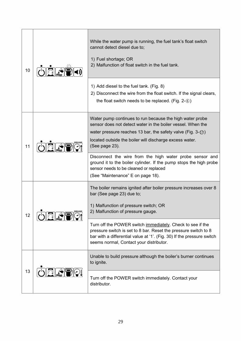
10
While the water pump is running, the fuel tank’s float switch cannot detect diesel due to; 1) Fuel shortage; OR 2) Malfunction of float switch in the fuel tank.
1) Add diesel to the fuel tank. (Fig. 8) 2) Disconnect the wire from the float switch. If the signal clears,
the float switch needs to be replaced. (Fig. 2-⑥)
11
Water pump continues to run because the high water probe sensor does not detect water in the boiler vessel. When the
water pressure reaches 13 bar, the safety valve (Fig. 3-○17 )
located outside the boiler will discharge excess water. (See page 23).
Disconnect the wire from the high water probe sensor and ground it to the boiler cylinder. If the pump stops the high probe sensor needs to be cleaned or replaced (See “Maintenance” E on page 18).
12
The boiler remains ignited after boiler pressure increases over 8 bar (See page 23) due to; 1) Malfunction of pressure switch; OR 2) Malfunction of pressure gauge.
Turn off the POWER switch immediately. Check to see if the pressure switch is set to 8 bar. Reset the pressure switch to 8 bar with a differential value at ‘1’. (Fig. 30) If the pressure switch seems normal, Contact your distributor.
13
Unable to build pressure although the boiler’s burner continues to ignite.
Turn off the POWER switch immediately. Contact your distributor.
30
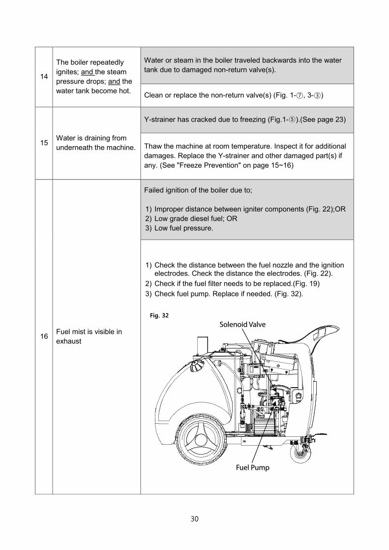
14
The boiler repeatedly ignites; and the steam pressure drops; and the water tank become hot.
Water or steam in the boiler traveled backwards into the water tank due to damaged non-return valve(s).
Clean or replace the non-return valve(s) (Fig. 1-⑦, 3-③)
15 Water is draining from underneath the machine.
Y-strainer has cracked due to freezing (Fig.1-⑤).(See page 23)
Thaw the machine at room temperature. Inspect it for additional damages. Replace the Y-strainer and other damaged part(s) if any. (See "Freeze Prevention" on page 15~16)
16 Fuel mist is visible in exhaust
Failed ignition of the boiler due to; 1) Improper distance between igniter components (Fig. 22);OR 2) Low grade diesel fuel; OR 3) Low fuel pressure.
1) Check the distance between the fuel nozzle and the ignition electrodes. Check the distance the electrodes. (Fig. 22).
2) Check if the fuel filter needs to be replaced.(Fig. 19) 3) Check fuel pump. Replace if needed. (Fig. 32).
Fig. 32
31
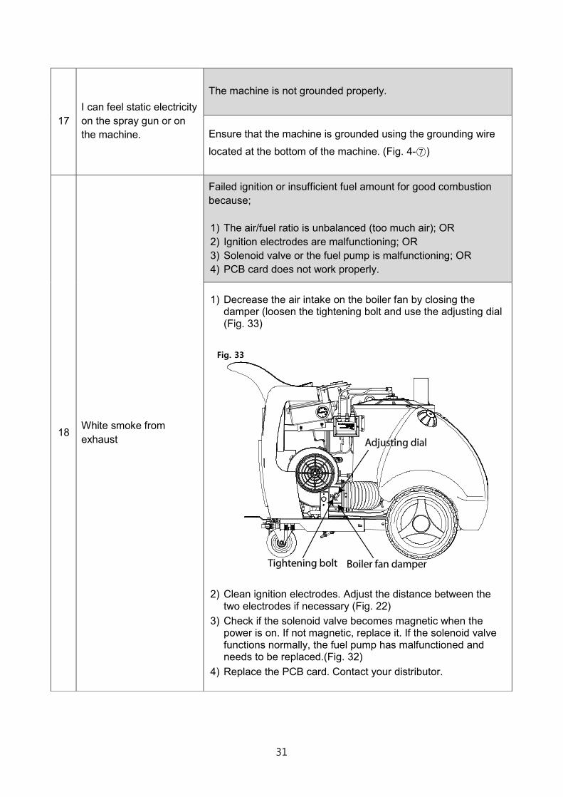
17 I can feel static electricity on the spray gun or on the machine.
The machine is not grounded properly.
Ensure that the machine is grounded using the grounding wire
located at the bottom of the machine. (Fig. 4-⑦)
18 White smoke from exhaust
Failed ignition or insufficient fuel amount for good combustion because; 1) The air/fuel ratio is unbalanced (too much air); OR 2) Ignition electrodes are malfunctioning; OR 3) Solenoid valve or the fuel pump is malfunctioning; OR 4) PCB card does not work properly.
1) Decrease the air intake on the boiler fan by closing the damper (loosen the tightening bolt and use the adjusting dial (Fig. 33)
Fig. 33
2) Clean ignition electrodes. Adjust the distance between the two electrodes if necessary (Fig. 22)
3) Check if the solenoid valve becomes magnetic when the power is on. If not magnetic, replace it. If the solenoid valve functions normally, the fuel pump has malfunctioned and needs to be replaced.(Fig. 32)
4) Replace the PCB card. Contact your distributor.
32
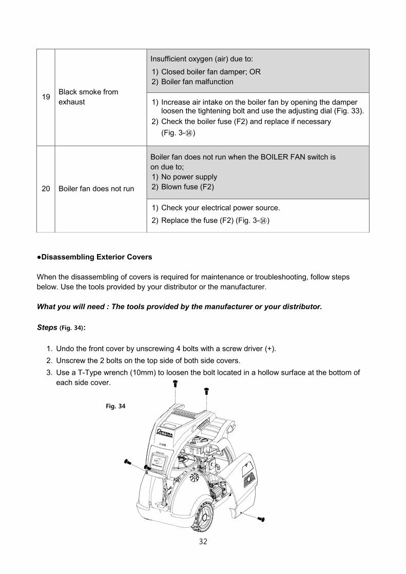
●Disassembling Exterior Covers When the disassembling of covers is required for maintenance or troubleshooting, follow steps below. Use the tools provided by your distributor or the manufacturer. What you will need : The tools provided by the manufacturer or your distributor. Steps (Fig. 34):
1. Undo the front cover by unscrewing 4 bolts with a screw driver (+). 2. Unscrew the 2 bolts on the top side of both side covers. 3. Use a T-Type wrench (10mm) to loosen the bolt located in a hollow surface at the bottom of
each side cover.
19 Black smoke from exhaust
Insufficient oxygen (air) due to:
1) Closed boiler fan damper; OR 2) Boiler fan malfunction
1) Increase air intake on the boiler fan by opening the damper loosen the tightening bolt and use the adjusting dial (Fig. 33).
2) Check the boiler fuse (F2) and replace if necessary (Fig. 3-⑭)
20 Boiler fan does not run
Boiler fan does not run when the BOILER FAN switch is on due to; 1) No power supply 2) Blown fuse (F2)
1) Check your electrical power source.
2) Replace the fuse (F2) (Fig. 3-⑭)
Fig. 34

33

![Optima SEII Manual Ver G2.3.00[English] - SJE Corporation fileThe Optima Steamer continues to pursue environmentally friendly and effective cleaning solutions. Optima Steamer which](https://img.pdfslide.us/doc/110x75/5ca7ccb188c99314128b7e8b/optima-seii-manual-ver-g2300english-sje-optima-steamer-continues-to-pursue.jpg)