Embed Size (px)
Citation preview
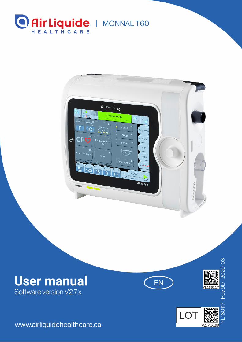
User manualSoftware version V2.7.x
www.airliquidehealthcare.ca
MONNAL T60
YL1
8011
7 - R
ev 9
D -
2020
-03
YL180117
V2.7.xI9D
EN

3
YL180117 - Rev. 9D - 2020-03
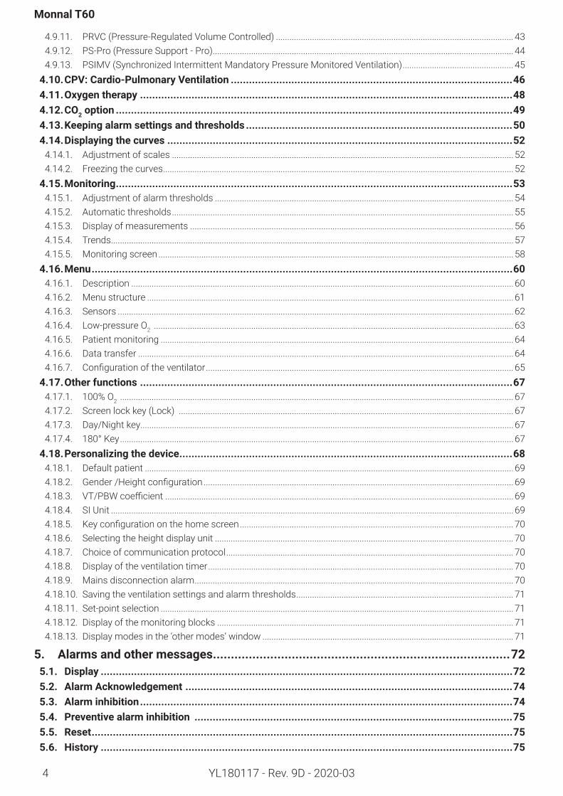
Contents1. Before use ...............................................................................................................71.1. Definitionsofuserwarnings ..........................................................................................................71.2. Intended use .................................................................................................................................71.3. Training .........................................................................................................................................71.4. Briefdescriptionofthedevice .......................................................................................................81.5. Symbolsandmarkingsonthedevice .............................................................................................91.6. Generalsafetyinstructions ..........................................................................................................11
2. Descriptionofthedevice .......................................................................................142.1. TerminologyUsed .......................................................................................................................142.2. Frontview ....................................................................................................................................142.3. Right-handside:Patientcircuitconnectionpanel ........................................................................152.4. Left-handside:Turbineairinletpanel ..........................................................................................152.5. Rearpanel ...................................................................................................................................15
3. Installationandcommissioning .............................................................................163.1. Unpacking ...................................................................................................................................163.2. Connectionsandcommissioning .................................................................................................16
3.2.1. Electrical power supply ................................................................................................................................................... 163.2.2. Oxygen supply ....................................................................................................................................................................163.2.3. Assembly of patient circuit and accessories ............................................................................................................... 173.2.4. CO2 Measurement Probe (IRMA™) ................................................................................................................................. 183.2.5. Humidifier ...........................................................................................................................................................................193.2.6. Nebulizer .............................................................................................................................................................................193.2.7. Interchangeable battery ................................................................................................................................................... 193.2.8. Applying power ..................................................................................................................................................................203.2.9. Automatic tests ................................................................................................................................................................21
4. Use ........................................................................................................................224.1. Start-upscreen ...........................................................................................................................224.2. Ventilationscreen .......................................................................................................................254.3. Homescreen(currentventilation) ...............................................................................................264.4. Ventilatorcontrols .......................................................................................................................274.5. Newpatient .................................................................................................................................29
4.5.1. Selecting the patient category ........................................................................................................................................ 294.5.2. Selecting the patient height and gender ....................................................................................................................... 30
4.6. Emergencyventilationstart-up ....................................................................................................314.7. Start/stopventilation .................................................................................................................324.8. Shuttingdowntheunit .................................................................................................................334.9. Ventilationmodes .......................................................................................................................34
4.9.1. Mode selection ..................................................................................................................................................................344.9.2. Ventilation settings ...........................................................................................................................................................344.9.3. Apnea ventilation adjustment ......................................................................................................................................... 354.9.4. VCV (controlled ventilation or assisted volume-controlled ventilation) .................................................................. 364.9.5. PCV (controlled ventilation or assisted pressure-controlled ventilation) ............................................................... 374.9.6. PSV (spontaneous ventilation with inspiratory assistance and PEEP) ................................................................. 384.9.7. SIMV ....................................................................................................................................................................................394.9.8. PSV / NIV (non-invasive ventilation) .............................................................................................................................. 404.9.9. CPAP (Continuous Positive Airway Pressure) ............................................................................................................. 414.9.10. Duo-Levels (Alternation of two CPAP levels) ............................................................................................................... 42
4
Monnal T60
YL180117 - Rev. 9D - 2020-03
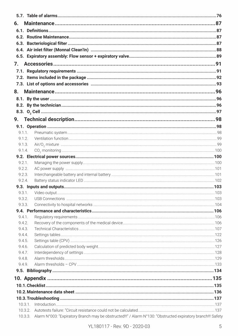
4.9.11. PRVC (Pressure-Regulated Volume Controlled) ......................................................................................................... 434.9.12. PS-Pro (Pressure Support - Pro) ..................................................................................................................................... 444.9.13. PSIMV (Synchronized Intermittent Mandatory Pressure Monitored Ventilation) ................................................. 45
4.10.CPV:Cardio-PulmonaryVentilation .............................................................................................464.11.Oxygentherapy ...........................................................................................................................484.12. CO2option ...................................................................................................................................494.13.Keepingalarmsettingsandthresholds ........................................................................................504.14.Displayingthecurves..................................................................................................................52
4.14.1. Adjustment of scales ....................................................................................................................................................... 524.14.2. Freezing the curves ...........................................................................................................................................................52
4.15.Monitoring ...................................................................................................................................534.15.1. Adjustment of alarm thresholds .................................................................................................................................... 544.15.2. Automatic thresholds ....................................................................................................................................................... 554.15.3. Display of measurements ............................................................................................................................................... 564.15.4. Trends ..................................................................................................................................................................................574.15.5. Monitoring screen .............................................................................................................................................................58
4.16. Menu ...........................................................................................................................................604.16.1. Description .........................................................................................................................................................................604.16.2. Menu structure ..................................................................................................................................................................614.16.3. Sensors ...............................................................................................................................................................................624.16.4. Low-pressure O2 ............................................................................................................................................................... 634.16.5. Patient monitoring ............................................................................................................................................................644.16.6. Data transfer ......................................................................................................................................................................644.16.7. Configurationoftheventilator ........................................................................................................................................ 65
4.17.Otherfunctions ...........................................................................................................................674.17.1. 100% O2 .............................................................................................................................................................................. 674.17.2. Screen lock key (Lock) .................................................................................................................................................... 674.17.3. Day/Night key.....................................................................................................................................................................674.17.4. 180° Key ..............................................................................................................................................................................67
4.18.Personalizingthedevice ..............................................................................................................684.18.1. Default patient ...................................................................................................................................................................694.18.2. Gender/Heightconfiguration ......................................................................................................................................... 694.18.3. VT/PBWcoefficient ..........................................................................................................................................................694.18.4. SI Unit ..................................................................................................................................................................................694.18.5. Keyconfigurationonthehomescreen ......................................................................................................................... 704.18.6. Selecting the height display unit .................................................................................................................................... 704.18.7. Choice of communication protocol ............................................................................................................................... 704.18.8. Display of the ventilation timer ....................................................................................................................................... 704.18.9. Mains disconnection alarm ............................................................................................................................................. 704.18.10. Saving the ventilation settings and alarm thresholds ................................................................................................ 714.18.11. Set-point selection ............................................................................................................................................................714.18.12. Display of the monitoring blocks ................................................................................................................................... 714.18.13. Display modes in the ‘other modes’ window ............................................................................................................... 71
5. Alarmsandothermessages ...................................................................................725.1. Display ........................................................................................................................................725.2. AlarmAcknowledgement ............................................................................................................745.3. Alarminhibition ...........................................................................................................................745.4. Preventivealarminhibition .........................................................................................................755.5. Reset ...........................................................................................................................................755.6. History ........................................................................................................................................75
5
YL180117 - Rev. 9D - 2020-03
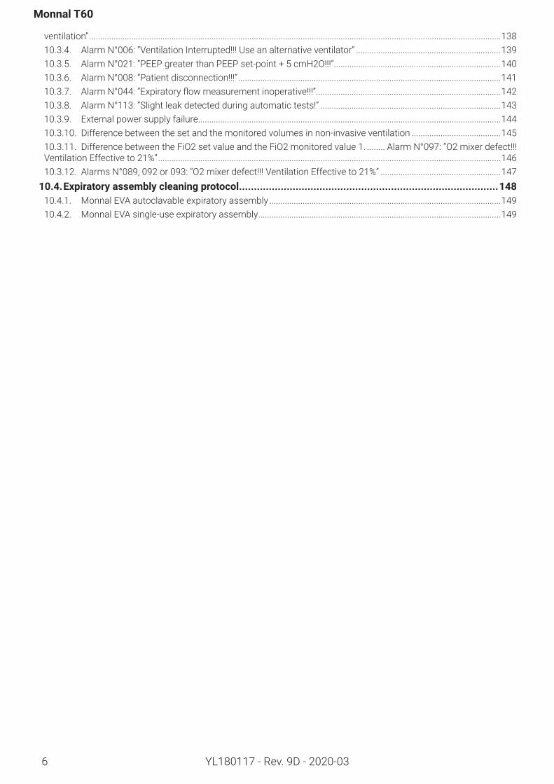
5.7. Table of alarms ............................................................................................................................76
6. Maintenance ..........................................................................................................876.1. Definitions ...................................................................................................................................876.2. RoutineMaintenance ...................................................................................................................876.3. Bacteriologicalfilter ....................................................................................................................876.4. Airinletfilter(MonnalClean’In) ..................................................................................................886.5. Expiratoryassembly:Flowsensor+expiratoryvalve ....................................................................89
7. Accessories ...........................................................................................................917.1. Regulatoryrequirements .............................................................................................................917.2. Itemsincludedinthepackage .....................................................................................................927.3. Listofoptionsandaccessories ..................................................................................................93
8. Maintenance ..........................................................................................................968.1. Bytheuser ..................................................................................................................................968.2. Bythetechnician .........................................................................................................................968.3. O2 Cell .........................................................................................................................................97
9. Technicaldescription .............................................................................................989.1. Operation ....................................................................................................................................98
9.1.1. Pneumatic system ............................................................................................................................................................989.1.2. Ventilation function ...........................................................................................................................................................999.1.3. Air/O2 mixture ................................................................................................................................................................... 999.1.4. CO2 monitoring ................................................................................................................................................................100
9.2. Electricalpowersources ............................................................................................................1009.2.1. Managing the power supply ..........................................................................................................................................1009.2.2. AC power supply ............................................................................................................................................................1019.2.3. Interchangeable battery and internal battery ............................................................................................................1019.2.4. Battery status indicator LED .........................................................................................................................................102
9.3. Inputsandoutputs .....................................................................................................................1039.3.1. Video output .....................................................................................................................................................................1039.3.2. USB Connections ...........................................................................................................................................................1039.3.3. Connectivity to hospital networks ...............................................................................................................................104
9.4. Performanceandcharacteristics ...............................................................................................1069.4.1. Regulatory requirements ...............................................................................................................................................1069.4.2. Recovery of the components of the medical device ................................................................................................1069.4.3. Technical Characteristics ..............................................................................................................................................1079.4.4. Settings tables .................................................................................................................................................................1229.4.5. Settings table (CPV) .......................................................................................................................................................1269.4.6. Calculation of predicted body weight ..........................................................................................................................1279.4.7. Interdependency of settings .........................................................................................................................................1289.4.8. Alarm thresholds .............................................................................................................................................................1299.4.9. Alarm thresholds – CPV ................................................................................................................................................133
9.5. Bibliography ..............................................................................................................................134
10. Appendix .............................................................................................................13510.1.Checklist ...................................................................................................................................13510.2.Maintenancedatasheet ............................................................................................................13610.3.Troubleshooting ........................................................................................................................137
10.3.1. Introduction ......................................................................................................................................................................13710.3.2. Autotests failure: “Circuit resistance could not be calculated ................................................................................13710.3.3. Alarm N°003: “Expiratory Branch may be obstructed!!!” / Alarm N°130: “Obstructed expiratory branch!!! Safety
6
Monnal T60
YL180117 - Rev. 9D - 2020-03
ventilation” .........................................................................................................................................................................................13810.3.4. Alarm N°006: “Ventilation Interrupted!!! Use an alternative ventilator” .................................................................13910.3.5. Alarm N°021: “PEEP greater than PEEP set-point + 5 cmH2O!!!” ...........................................................................14010.3.6. Alarm N°008: “Patient disconnection!!!” ......................................................................................................................14110.3.7. AlarmN°044:“Expiratoryflowmeasurementinoperative!!!” ...................................................................................14210.3.8. Alarm N°113: “Slight leak detected during automatic tests!” .................................................................................14310.3.9. External power supply failure ........................................................................................................................................14410.3.10. Difference between the set and the monitored volumes in non-invasive ventilation ........................................14510.3.11. Difference between the FiO2 set value and the FiO2 monitored value 1. ........ Alarm N°097: “O2 mixer defect!!! Ventilation Effective to 21%” ..........................................................................................................................................................14610.3.12. Alarms N°089, 092 or 093: “O2 mixer defect!!! Ventilation Effective to 21%” ......................................................147
10.4.Expiratoryassemblycleaningprotocol .......................................................................................14810.4.1. Monnal EVA autoclavable expiratory assembly ........................................................................................................14910.4.2. Monnal EVA single-use expiratory assembly .............................................................................................................149
Before use
YL180117 - Rev. 9D - 2020-03 7
1. Before use
1.1. Definitionsofuserwarnings
Warning
Warns the user of the risks associated with the use or misuse of the device:- occurrence of a technical problem or device mal-function,- slight or serious injury to the patient.If the risk to the patient is very high, the warning will appear in bold lettering.
Information
Highlights a particular item of information.
1.2. Intended use Monnal T60 is a standalone ventilator using air (pro-pelled by a blower) used to treat infants (3 kg and above), children, and adults. It is not intended for neo-natal ventilation.It is used for patient ventilation to compensate for or mitigate respiratory failure. Contact with the patient is made via an adequate patient interface (e.g., mask or endotrachealtube),whichallowsairtoflowfromtheventilator into the lungs.It is for use by hospital personnel (doctors, nurses, etc.) and is used: • for pre-admission transportation,*• for transportation within a hospital,• for transportation between hospitals,*• for intra-hospital emergencies,• in post-operative recovery rooms,• in intensive care.*Land transportation and air ambulances.
Medicalelectricalsystem
Monnal T60 is part of the medical electrical system consisting of the following components:• a CO2 measurement probe (IRMA™)• aMonnalClean’In(HEPA)filter• ahumidifier• a nebulizer• an interchangeable battery• an external power supply• oxygen from a supply network, cylinder, or concen-
trator.Monnal T60 provides monitoring for the following re-spiratory gases: oxygen and carbon dioxide (using the optional IRMA probe).
Requisiteknowledge
Persons intending to operate this ventilator must be trained in its use.Only persons who have fully read and understood this manual are authorized to handle and use this ventila-tor. The present manual is intended to give all informa-tion necessary for the correct utilisation of this venti-lator, but is in no way intended to replace the medical prescription that is essential for adjusting the appara-tus according to patient needs.
1.3. TrainingThere are two main types of training:• training in the use of the ventilator,• training in the routine maintenance of the ventilator.
Trainingintheuseoftheventilator
Training in the use of the ventilator takes around thir-ty minutes. It is carried out during installation in the hospital department by Air Liquide Medical Systems staff or by an authorized Air Liquide Medical Systems distributor. This training includes: • validation of the intended use and description of the ventilator, • installation and commissioning,• comprehensive presentation of the operating func-tions of the ventilator,• practice on a test lung, adapted to the type of hos-pital service.This training can be repeated or covered in more depth at the request of the users, by contacting the usual Air Liquide Medical Systems representative.
Traininginroutinemaintenance
Training in the routine maintenance of the ventilator takes around thirty minutes. It is carried out during de-livery to the biomedical department, or during installa-tion in the hospital department by Air Liquide Medical Systems staff or by an authorized Air Liquide Medi-cal Systems distributor. It is intended for biomedical teams and equipment supervisors in the department.The training includes:• consumables management• daily recommended maintenance practices• monitoring minor alarms
Monnal T60
YL180117 - Rev. 9D - 2020-038
1.4. BriefdescriptionofthedeviceMonnal T60 can supply tidal volumes from 20 to 2000mLinvolume-controlledmode,andinsufflationpressures from 5 to 60 cmH2O in pressure-controlled mode.It can also supply FiO2 from 21 to 100%. This is contin-uously monitored.It features the following ventilation modes and func-tions:VCV (controlled ventilation or assisted volume-con-trolled ventilation) PCV(controlled ventilation or assisted pressure-con-trolled ventilation) PSV (spontaneous ventilation with inspiratory assis-tance and PEEP) PSV / NIV (spontaneous ventilation with inspiratory assistance/non-invasive ventilation)CPAP(Continuous Positive Airway Pressure) SIMV (intermittent assisted controlled ventilation)PSIMV (intermittent assisted pressure-controlled ventilation)Duo-Levels(Alternation of two CPAP levels)NIV (Non Invasive Ventilation)PRVC (Pressure-regulated volume controlled ventila-tion)PS-Pro (Spontaneous ventilation with inspiratory as-sistance, PEEP and servomechanism frequency)OxygentherapyCPV (Cardio-Pulmonary Ventilation)The device is equipped with an 8.4-inch colour touch screen, an ergonomic control wheel and a functional interface for adjustment of the various settings and ventilation parameters. PatientenvironmentDuring normal use, the patient is lying on a hospital bed with the Monnal T60 device placed close by. All parts of the medical electrical system are suitable for use in the patient environment.UserpositionThe human machine interface of the device faces the user so that the user can make the necessary adjust-ments with the control wheel and read the information displayed on the screen. The recommended distance depends on the environment, the ambient lighting and the user’s visual acuity. The back of the device is ac-cessible to the user.
9
Before use
YL180117 - Rev. 9D - 2020-03
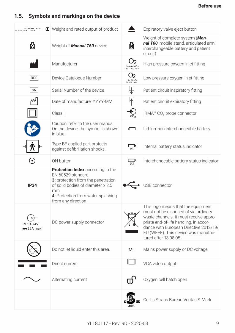
1.5. Symbolsandmarkingsonthedevice
Weight and rated output of product Expiratory valve eject button
Weight of Monnal T60 device
Weight of complete system (Mon-nal T60, mobile stand, articulated arm, interchangeable battery and patient circuit)
Manufacturer Highpressureoxygeninletfitting
Device Catalogue Number Lowpressureoxygeninletfitting
Serial Number of the device Patientcircuitinspiratoryfitting
Date of manufacture: YYYY-MM Patientcircuitexpiratoryfitting
Class II IRMA™ CO2 probe connector
Caution: refer to the user manualOn the device, the symbol is shown in blue.
Lithium-ion interchangeable battery
Type BF applied part protects againstdefibrillationshocks. Internal battery status indicator
ON button Interchangeable battery status indicator
IP34
ProtectionIndexaccording to the EN 60529 standard3:protection from the penetration ofsolidbodiesofdiameter≥2.5mm4: Protection from water splashing from any direction
USB connector
DC power supply connector
This logo means that the equipment must not be disposed of via ordinary waste channels. It must receive appro-priate end-of-life handling, in accor-dance with European Directive 2012/19/EU (WEEE). This device was manufac-tured after 13.08.05.
Do not let liquid enter this area. Mains power supply or DC voltage
Direct current VGA video output
Alternating current Oxygen cell hatch open
Curtis Straus Bureau Veritas S-Mark
10
Monnal T60
YL180117 - Rev. 9D - 2020-03
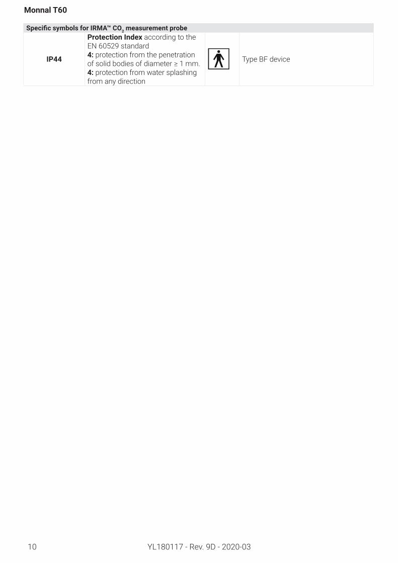
SpecificsymbolsforIRMA™CO2measurementprobe
IP44
ProtectionIndexaccording to the EN 60529 standard4: protection from the penetration ofsolidbodiesofdiameter≥1mm.4: protection from water splashing from any direction
Type BF device
Before use
YL180117 - Rev. 9D - 2020-03 11
1.6. Generalsafetyinstructions
Useofoxygen
• Precautions in case of oxygen leak:• No smoking• Avoidanyflameorsourceofsparks• Disconnect the oxygen source• Ventilateroomduringleakageandatleast20 minutesafterleakage.• Air one‘s own clothing.
• The device must not be in operation near any incandescent source.• Thisventilatormustnotbeusedwithinflammableanestheticagentsorexplosiveproducts.• Do not use the equipment with helium or helium mixed with another gas.• The ventilator does not directly administer nitric oxide but can be used concomitantly with a Nitric Oxide
administration system, provided that the manufacturer of the nitric oxide delivery system has validated its use.
• Do not use the devicewith components that have been contaminated by inflammable substances (e.g.grease, oil, etc.).
• The internal components of the device were degreased before delivery or use a type of grease which is compatible with oxygen. Do not grease or lubricate any part of the device.
• Medical grade oxygen must be used (i.e. dust-free and dry, H2O < 20 mg/m3).• Thesupplypressuremustbebetween280kPa(2.8 bars)and600kPa(6bars).• When the device is not in use, it is recommended that you disconnect all oxygen sources from it.
Usewithadefibrillator
• When using the Monnal T60 andadefibrillatorsimultaneously, thedefibrillationshock in thepresenceofenrichedoxygenandcombustibles(suchastextiles)cancauseanexplosionorfirewhichcouldinjurethepatient and bystanders.
• It is recommended to use adhesive electrodes. • Duringthedefibrillation:• remove the oxygen mask or the nasal cannula and keep it at least 1 m from the patient’s torso;• if the patient is intubated, leave the ventilator connected;• ensure that the oxygen-enriched air at the outlet of the expiratory valve is not facing the patient’s torso.
Electricalpowersupply
• Check that the voltage in the mains socket used matches the electrical characteristics of the ventilator (indicated on the rear panel of the power supply adapter).
• Use only the mains cable and mains power supply box supplied with the device.• If an external power supply is used, check that the voltage and current used match the electrical characteristics
of the ventilator (indicated on the side of the ventilator).• The mains power supply adapter is not protected from splashes of water (IPX0), unlike the device itself,
which complies with IPX4 during battery-powered operation. • This ventilator has an internal battery and an interchangeable battery. The device must be connected to the mains
regularly to maintain the battery charge at a suitable level.• In the event of any doubt about the condition of the mains power supply cable, use the device on its internal
battery only.• In case of long battery-powered operation, we recommend keeping a spare interchangeable battery on hand.• Do not use antistatic or electrically conductive pipes.• The user must not touch the patient and the equipment enclosures at the same time.
Monnal T60
YL180117 - Rev. 9D - 2020-0312
Internalbatteryelectricalpowersupply
• The internal battery is a backup power source only. If connection to the mains power supply (primary power source) is impossible, an interchangeable battery (secondary power source) must be used. Using the internal battery as the main power source can cause ventilation to stop unexpectedly.
IPProtection
• To ensure the IP protection level of the device is maintained during normal use, it is essential that all removable components(airfilter,expiratoryassembly,O2sensorcoverandtherearplasticpanel)arefittedinplace
Electromagneticcompatibility
• Thepresenceofequipmentasdiathermyunits,highfrequencyelectro-surgicalequipment,defibrillatorsandcellular telephones or of electromagnetic interferences exceeding EN 60601-1-2 levels in its vicinity may interfere with the normal operation of the ventilator.
• The Monnal T60 should not be placed next to or on top of this equipment. If such use is necessary, the Monnal T60 should be observed together with the other ventilators to ensure that they are operating normally.
• Donotusethisventilatorinaspecificallymagneticenvironment(MRI,NMR,etc.).• Monnal T60 is compliant with the requirements defined in standard EN 60601-1-2 relating to the
electromagnetic compatibility of medical devices. Precautionary measures are required with this device in terms of EMC and the devices must be installed and put into operation in accordance with the EMC information provided in this user manual.
• The replacing of cables or internal components with cables or components that are not supplied by Air Liquide Medical Systems may result in an increase in emissions or a decrease in the immunity of the device.
Connectiontootherelectricaldevices
• Donot connect thedevice toother electrical appliancesnotmentioned in thisusermanualwithoutfirstconsulting the manufacturers concerned or a specialist.
• Devices connected to the inputs and signal outputs must comply with the 60601-1 Standard.
Set-up
• The device must not be put into service immediately after storage or transportation where the temperature and humidity were different from the recommended operating conditions.
• Before each use, check that the audible and visual alarms are working correctly and carry out the checks listed in the appendix (see section ““10.1 Checklist”).
• The ventilator should not be covered or positioned in such a way that its functioning or performance are affected. Always leave some space around the device: for example, never place the ventilator close to a curtainwhichcouldimpedethefreshairflowandcauseoverheating.
• If the Monnal T60 is installed on the universal support (KA010400), follow the instructions in the assembly manual. Ensure that the structure or unit (bed rail, for example) onto which the universal support is mounted can support the weight of the Monnal T60.
Use
• The manufacturer has tried to anticipate most of the possible malfunction scenarios of this ventilator, and these are normally monitored by the internal monitoring system. It is nevertheless recommended, in cases of complete patient dependence, that you provide an additional, fully autonomous system which can be used to checktheeffectivenessoftheventilation,aswellasaback-updevice,suchasasuitablemanualinsufflator.
• Lack of an alternative means of ventilation may result in patient death should the ventilator fail.• If the accessories used are not compliant with the manufacturer‘s recommendations, the manufacturer
accepts no responsibility in the event of an incident.• Do not expose the device to direct sunlight. • Do not use Monnal T60 in a hyperbaric chamber.• The device and its accessories (masks, circuits, etc.) are Latex-free.• The air inlets located at the back and side of the device must be completely unobstructed. • Tooperatethedevicefromambientair,aMonnalClean-In(HEPA)filtermustbeusedattheventilatorinlet.ThisfilterisrecommendedbyAir Liquide Medical Systems.
• Donotusetheventilatorinanexplosiveornicotine-ladenatmosphere(cigarettesmoke,fire,etc.).• In order to prevent dust from entering:• between ventilator uses in the bag, close the inspiratory limb cap;
Before use
YL180117 - Rev. 9D - 2020-03 13
• betweenventilatorusesinthebag,leaveabacteriologicalfilterorpatientcircuitontheinspiratoryoutletof the ventilator;• duringcleaning,leaveabacteriologicalfilterorapatientcircuitontheinspiratoryoutletoftheventilator;• clean the inside of the bag regularly.
Transportation
• During transportation, we recommend that you use the device in its protective carry bag. The case must be securely fastened in the vehicle using the strap loops provided for the purpose.
• The device must not be subjected to violent impact.• Use the carry bag recommended by Air Liquide Medical Systems only.• During transport, the use of Monnal T60 outside of its bag does not ensure compliance with EN 13718-1, EN
1789 and EN 794-3 standards.
Riskofcross-contamination
• Reusing single-use accessories or consumables carries the risk of patient cross-contamination. This risk also arises if reusable accessories or consumables are not sterilized between each use.
• The breathing tube,mask, patient circuit, bacteriological filters, expiratory valve, humidification chamber,CO2 probe or nebulizer adapters are part of the air path and can be contaminated under normal operating conditions, and in the event of a single fault conditionbybodily fluids, secretionsor gasexhaledby thepatient.
Maintenance
• This ventilator must be checked regularly. To plan and keep a record of all maintenance, operations, refer to the maintenance sheet in the appendix.
• In accordance with the EN 60601-1 Standard (Appendix A, Para. 6.8.2.b), the manufacturer, the assembler, the installer or the importer shall only consider itself responsible for the effects on the safety, reliability and characteristics of a device if:• “Assembly,extensions,adjustments,modificationsorrepairshavebeencarriedoutbypersonswhomithas authorized;• The electrical installation in the corresponding area is compliant with IEC recommendations.• The device is used in conformity with the instructions for use.”
• The approved technician must use only Air Liquide Medical Systems spare parts when carrying out routine maintenance of the device.
• Donotuseabrasivepowders,alcohol,acetoneorothereasilyflammablesolvents.• The device must be disconnected from the mains during any procedure such as maintenance or cleaning.
Recommendationsforaspiration
• Aspiration may be carried out according to different methods: fully unplugging the circuit, opening a respiratory circuit connection, or closed system.
• When using a breathing tube in a closed system, it is advised to use the PAC mode with the parameters adjusted to the patient and, if tolerated, a PEEP of at least 3 cmH2O.
Medicalcontraindications
• Certain conditions require appropriate treatment before ventilator use. The absence of such treatment may have negative effects on the patient‘s health.
• Monnal T60 is not suitable for very low-weight patients (premature infants, and infants under 3 kg).• Monnal T60cannotbeusedinmagneticresonanceimaging(MRI)roomsunlessasufficientlylongcircuit
is added.• Monnal T60 is not designed for hyperbaric ventilation.• The CPV ventilation function (cardiopulmonary ventilation, optional) is not suitable for children and infants.
RecommendationsforusingtheMASIMOIRMA™CO2measurementprobe
See “4.12. CO2 option”, page 49.
Monnal T60
14 YL180117 - Rev. 9D - 2020-03
2. Descriptionofthedevice
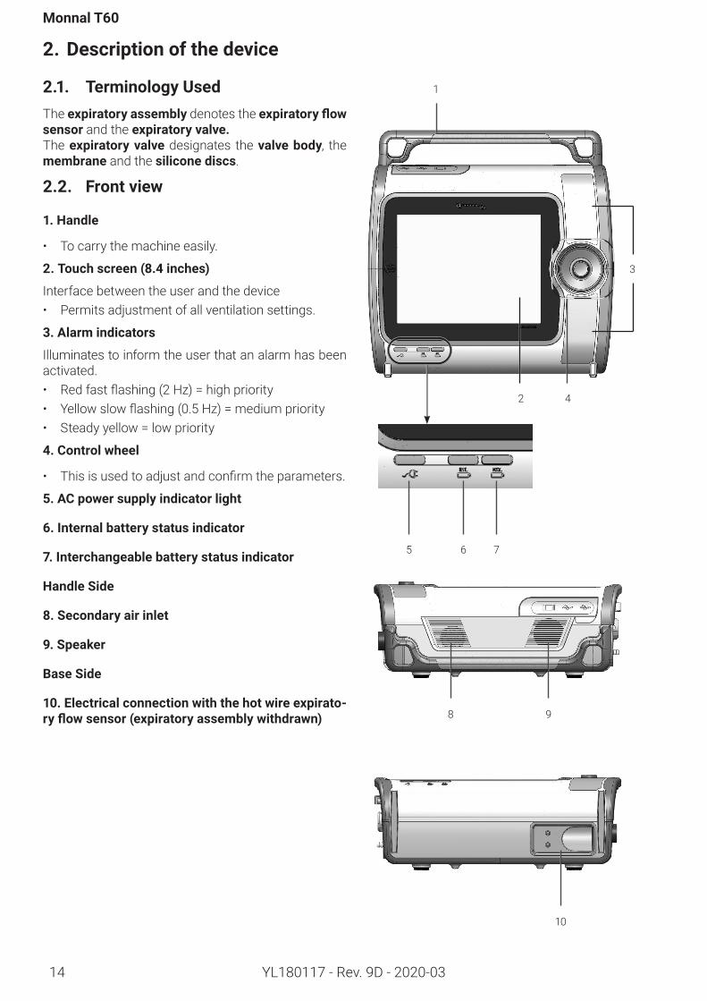
2.1. TerminologyUsedTheexpiratoryassembly denotes the expiratoryflowsensor and the expiratoryvalve.Theexpiratoryvalvedesignates the valvebody, the membrane and the siliconediscs.
2.2. Frontview
1. Handle
• To carry the machine easily.
2.Touchscreen(8.4inches)
Interface between the user and the device• Permits adjustment of all ventilation settings.
3.Alarmindicators
Illuminates to inform the user that an alarm has been activated.• Redfastflashing(2Hz)=highpriority• Yellowslowflashing(0.5Hz)=mediumpriority• Steadyyellow=lowpriority
4.Controlwheel
• Thisisusedtoadjustandconfirmtheparameters.
5.ACpowersupplyindicatorlight
6.Internalbatterystatusindicator
7.Interchangeablebatterystatusindicator
HandleSide
8.Secondaryairinlet
9.Speaker
BaseSide
10.Electricalconnectionwiththehotwireexpirato-ryflowsensor(expiratoryassemblywithdrawn) 8 9
10
5
1
6 7
4
3
2
Descriptionofthedevice
15YL180117 - Rev. 9D - 2020-03
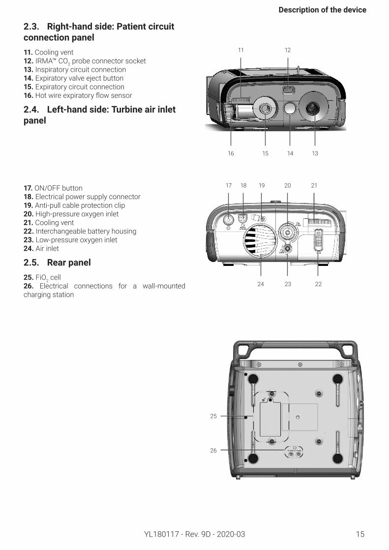
2.3. Right-handside:Patientcircuitconnectionpanel11. Cooling vent12. IRMA™ CO2 probe connector socket 13. Inspiratory circuit connection 14. Expiratory valve eject button 15. Expiratory circuit connection 16.Hotwireexpiratoryflowsensor
2.4. Left-handside:Turbineairinletpanel
16
11
17 18 19 20 21
24
25
26
23 22
12
15 14 13
17. ON/OFF button18. Electrical power supply connector19. Anti-pull cable protection clip20. High-pressure oxygen inlet21. Cooling vent22. Interchangeable battery housing 23. Low-pressure oxygen inlet24. Air inlet
2.5. Rearpanel25. FiO2 cell 26. Electrical connections for a wall-mounted charging station
Monnal T60
16 YL180117 - Rev. 9D - 2020-03
3. Installationandcommissioning
3.1. UnpackingRemove the ventilator from the packaging and place it horizontally on a table.Unwrap the accessories supplied with the ventilator.
Before using on a new patient, and before the first use of this device, you must clean and disinfect the accessories (see section “6 Maintenance”).
3.2. Connectionsandcommissioning
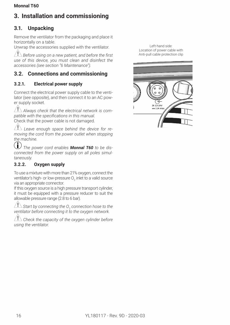
3.2.1. Electricalpowersupply
Connect the electrical power supply cable to the venti-lator (see opposite), and then connect it to an AC pow-er supply socket.
Always check that the electrical network is com-patible with the specifications in this manual. Check that the power cable is not damaged.
Leave enough space behind the device for re-moving the cord from the power outlet when stopping the machine.
The power cord enables Monnal T60 to be dis-connected from the power supply on all poles simul-taneously.3.2.2. Oxygensupply
To use a mixture with more than 21% oxygen, connect the ventilator’s high- or low-pressure O2 inlet to a valid source via an appropriate connector.If this oxygen source is a high pressure transport cylinder, it must be equipped with a pressure reducer to suit the allowable pressure range (2.8 to 6 bar).
Start by connecting the O2 connection hose to the ventilator before connecting it to the oxygen network.
Check the capacity of the oxygen cylinder before using the ventilator.
Left-hand side: Location of power cable with Anti-pull cable protection clip
Installationandcommissioning
17YL180117 - Rev. 9D - 2020-03
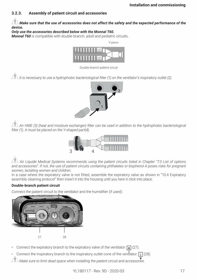
3.2.3. Assemblyofpatientcircuitandaccessories
Make sure that the use of accessories does not affect the safety and the expected performance of the device. Only use the accessories described below with the Monnal T60.Monnal T60 is compatible with double-branch, adult and pediatric circuits.
Y-piece
Double-branch patient circuit
It is necessary to use a hydrophobic bacteriological filter (1) on the ventilator’s inspiratory outlet (2).
1
2
An HME (3) (heat and moisture exchanger) filter can be used in addition to the hydrophobic bacteriological filter (1). It must be placed on the Y-shaped part(4).
3 4
Air Liquide Medical Systems recommends using the patient circuits listed in Chapter “7.3 List of options and accessories”. If not, the use of patient circuits containing phthalates or bisphenol A poses risks for pregnant women, lactating women and children.Inacasewheretheexpiratoryvalve isnotfitted,assembletheexpiratoryvalveasshownin“10.4 Expiratory assembly cleaning protocol” then insert it into the housing until you here it click into place.
Double-branchpatientcircuit
Connectthepatientcircuittotheventilatorandthehumidifier(ifused):
27 28
• Connect the expiratory branch to the expiratory valve of the ventilator: (27).
• Connect the inspiratory branch to the inspiratory outlet cone of the ventilator: (28).
Make sure to limit dead space when installing the patient circuit and accessories.
Monnal T60
18 YL180117 - Rev. 9D - 2020-03
When using the equipment on a patient for the first time, make sure that you follow the hospital’s hygiene
protocol for new single-use equipment or adequately sterilized reusable equipment. The accessories and con-sumables (patient circuit, masks, expiratory valves, adapters, nebulizer, etc.) are generally available in single-use and autoclavable versions.
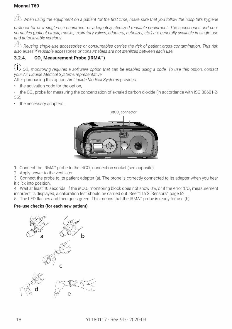
Reusing single-use accessories or consumables carries the risk of patient cross-contamination. This risk also arises if reusable accessories or consumables are not sterilized between each use. 3.2.4. CO2MeasurementProbe(IRMA™)
CO2 monitoring requires a software option that can be enabled using a code. To use this option, contact your Air Liquide Medical Systems representativeAfter purchasing this option, Air Liquide Medical Systems provides:• the activation code for the option,• the CO2probeformeasuringtheconcentrationofexhaledcarbondioxide(inaccordancewithISO 80601-2-55),• the necessary adapters.
etCO2 connector
1. Connect the IRMA™ probe to the etCO2 connection socket (see opposite).2. Apply power to the ventilator.3. Connect the probe to its patient adapter (a). The probe is correctly connected to its adapter when you hear it click into position.4. Wait at least 10 seconds. If the etCO2 monitoring block does not show 0%, or if the error ‘CO2 measurement incorrect’ is displayed, a calibration test should be carried out. See “4.16.3. Sensors”, page 62.5. TheLEDflashesandthengoesgreen.ThismeansthattheIRMA™probeisreadyforuse(b).
Pre-usechecks(foreachnewpatient)
Installationandcommissioning
19YL180117 - Rev. 9D - 2020-03
1. Connect the sensor to the patient adapter (a). A click should be heard when the sensor is properly connected to the adapter.2. Ensure that the etCO2 monitoring block is displaying data.3. Connect the IRMA™ probe, equipped with its adapter, to the Y-piece on the patient circuit (c).4. Connect the IRMA™ probe to the patient’s endotracheal tube (d).5. Position the IRMA™ probe (e) (see photo opposite).
The probe sends information and alarms to the Monnal T60. The probe has an LED indicating the following statuses:LED status DescriptionContinuous green OKFlashing green Calibration in progressContinuous red Probe errorFlashing red Checking the adapter
3.2.5. Humidifier
Ifthisventilatorisusedwithahumidifier,ensurethatitisalwaysplacedlowerthantheventilatorandthepatient.Itisalsorecommendedthatyouusepatientcircuitsequippedwithwatertrapswhenusingahumidifier.
Remember to empty the water traps regularly during ventilation.
Ensure that water does not enter the unit during handling of the patient circuit or the humidifier (if used). If this occurs, immediately stop using the device, and contact the Technical Department.
Humidification may increase the resistance of the filters used in the patient circuit. The filters should be tested frequently to check for an increase in resistance or blockage.3.2.6. Nebulizer
Y-piece respiratory filters can prevent medication from being effective: their use is therefore not recom-mended,
The precision of the expired volume can be impaired: a protective filter can then be used at the expiration end.
Nebulization may increase the resistance of the filters used in the patient circuit. The filters should be test-ed frequently to check for an increase in resistance or blockage. 3.2.7. Interchangeablebattery
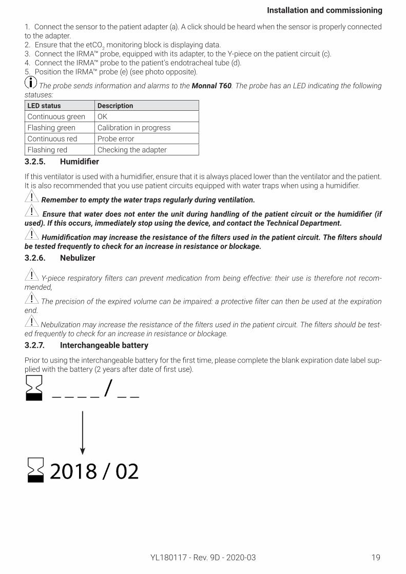
Priortousingtheinterchangeablebatteryforthefirsttime,pleasecompletetheblankexpirationdatelabelsup-pliedwiththebattery(2yearsafterdateoffirstuse).
Monnal T60
20 YL180117 - Rev. 9D - 2020-03
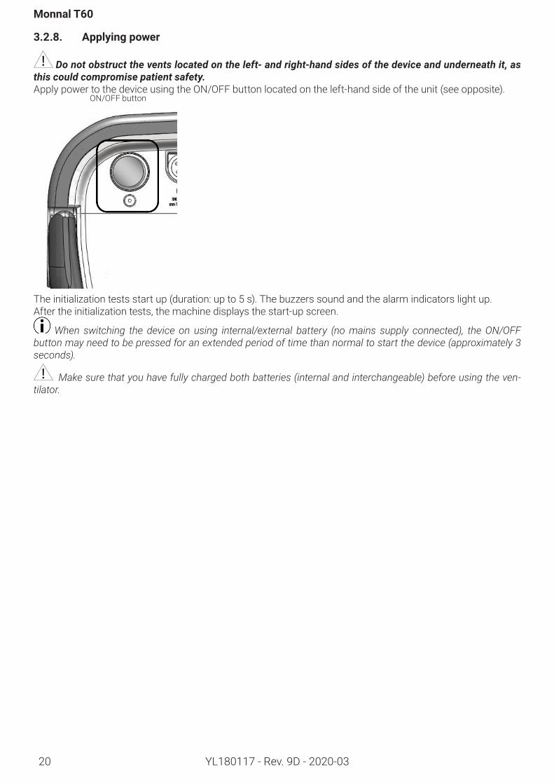
3.2.8. Applyingpower
Do not obstruct the vents located on the left- and right-hand sides of the device and underneath it, as this could compromise patient safety.Apply power to the device using the ON/OFF button located on the left-hand side of the unit (see opposite).
ON/OFF button
The initialization tests start up (duration: up to 5 s). The buzzers sound and the alarm indicators light up.After the initialization tests, the machine displays the start-up screen.
When switching the device on using internal/external battery (no mains supply connected), the ON/OFF button may need to be pressed for an extended period of time than normal to start the device (approximately 3 seconds).
Make sure that you have fully charged both batteries (internal and interchangeable) before using the ven-tilator.
Installationandcommissioning
21YL180117 - Rev. 9D - 2020-03
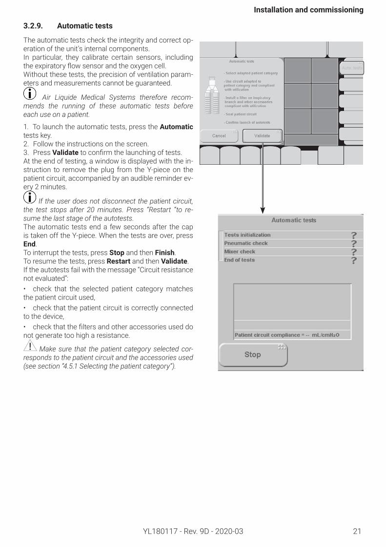
3.2.9. Automatictests
The automatic tests check the integrity and correct op-eration of the unit’s internal components. In particular, they calibrate certain sensors, including theexpiratoryflowsensorandtheoxygencell.Without these tests, the precision of ventilation param-eters and measurements cannot be guaranteed.
Air Liquide Medical Systems therefore recom-mends the running of these automatic tests before each use on a patient.
1. To launch the automatic tests, press the Automatic tests key.2. Follow the instructions on the screen.3. Press Validatetoconfirmthelaunchingoftests.At the end of testing, a window is displayed with the in-struction to remove the plug from the Y-piece on the patient circuit, accompanied by an audible reminder ev-ery 2 minutes.
If the user does not disconnect the patient circuit, the test stops after 20 minutes. Press “Restart “to re-sume the last stage of the autotests.The automatic tests end a few seconds after the cap is taken off the Y-piece. When the tests are over, press End.To interrupt the tests, press Stop and then Finish. To resume the tests, press Restart and then Validate. If the autotests fail with the message “Circuit resistance not evaluated”:• check that the selected patient category matches the patient circuit used,• check that the patient circuit is correctly connected to the device,• checkthatthefiltersandotheraccessoriesuseddonot generate too high a resistance.
Make sure that the patient category selected cor-responds to the patient circuit and the accessories used (see section “4.5.1 Selecting the patient category”).
Monnal T60
22 YL180117 - Rev. 9D - 2020-03
4. UseThis ventilator is controlled mainly via the touch screen and the control wheel.
Avoid using any object that might scratch the screen.
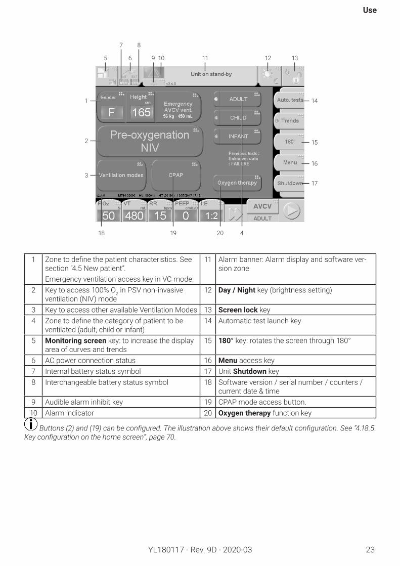
4.1. Start-upscreenThis screen is displayed when the machine starts up.The display zone (green band) says ‘Unit on stand-by’.The start-up screen is used to:• Select the ventilation mode, • Start ventilation,• Choose the patient category,• Start the automatic tests,• Shut down the unit.It also displays:• The current software version,• Ventilation time counter,• The power-on time counter,• The time and date.
23
Use
YL180117 - Rev. 9D - 2020-03
1 Zonetodefinethepatientcharacteristics.Seesection “4.5 New patient”.Emergency ventilation access key in VC mode.
11 Alarm banner: Alarm display and software ver-sion zone
2 Key to access 100% O2 in PSV non-invasive ventilation (NIV) mode
12 Day/Night key (brightness setting)
3 Key to access other available Ventilation Modes 13 Screenlock key4 Zonetodefinethecategoryofpatienttobe
ventilated (adult, child or infant)14 Automatic test launch key
5 Monitoringscreen key: to increase the display area of curves and trends
15 180° key: rotates the screen through 180°
6 AC power connection status 16 Menu access key 7 Internal battery status symbol 17 Unit Shutdown key 8 Interchangeable battery status symbol 18 Software version / serial number / counters /
current date & time9 Audible alarm inhibit key 19 CPAP mode access button.
10 Alarm indicator 20 Oxygentherapy function key
Buttons (2) and (19) can be configured. The illustration above shows their default configuration. See “4.18.5. Key configuration on the home screen”, page 70.
5
7
6
8
9 10 11 12 13
18 19 20 4
14
15
16
17
1
2
3
24
Monnal T60
YL180117 - Rev. 9D - 2020-03
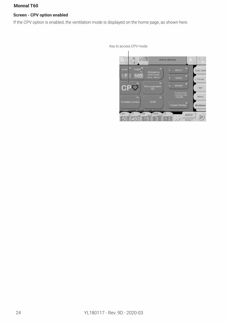
Screen-CPVoptionenabled
If the CPV option is enabled, the ventilation mode is displayed on the home page, as shown here.
Key to access CPV mode
25
Use
YL180117 - Rev. 9D - 2020-03
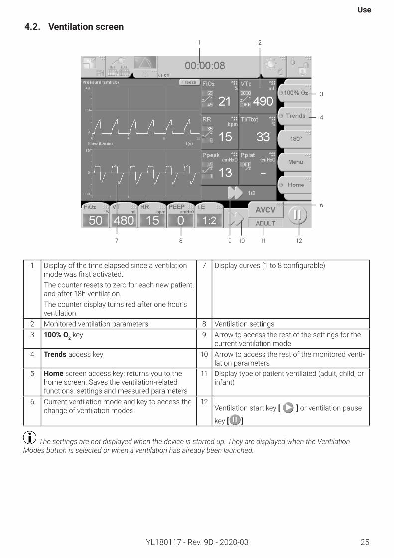
1 Display of the time elapsed since a ventilation modewasfirstactivated.The counter resets to zero for each new patient, and after 18h ventilation.The counter display turns red after one hour’s ventilation.
7 Displaycurves(1to8configurable)
2 Monitored ventilation parameters 8 Ventilation settings3 100% O2 key 9 Arrow to access the rest of the settings for the
current ventilation mode4 Trends access key 10 Arrow to access the rest of the monitored venti-
lation parameters5 Home screen access key: returns you to the
home screen. Saves the ventilation-related functions: settings and measured parameters
11 Display type of patient ventilated (adult, child, or infant)
6 Current ventilation mode and key to access the change of ventilation modes
12Ventilation start key [ ] or ventilation pause
key [ ]
The settings are not displayed when the device is started up. They are displayed when the Ventilation Modes button is selected or when a ventilation has already been launched.
4.2. Ventilationscreen
7 8 109 11 12
1 2
3
4
6
26
Monnal T60
YL180117 - Rev. 9D - 2020-03
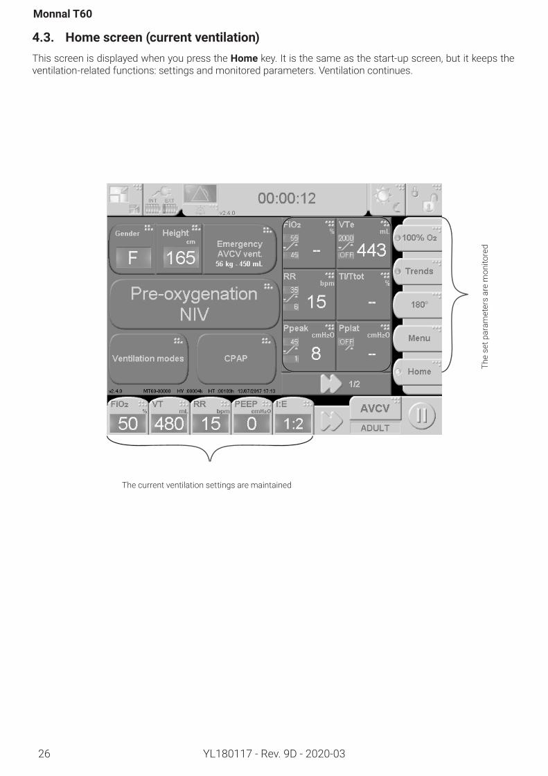
4.3. Homescreen(currentventilation)This screen is displayed when you press the Home key. It is the same as the start-up screen, but it keeps the ventilation-related functions: settings and monitored parameters. Ventilation continues.
The current ventilation settings are maintainedTh
e se
t par
amet
ers
are
mon
itore
d
27
Use
YL180117 - Rev. 9D - 2020-03
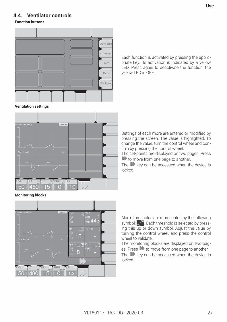
4.4. VentilatorcontrolsFunctionbuttons
Each function is activated by pressing the appro-priate key. Its activation is indicated by a yellow LED. Press again to deactivate the function: the yellow LED is OFF.
Ventilationsettings
Settingsofeachmoreareenteredormodifiedbypressing the screen. The value is highlighted. To change the value, turn the control wheel and con-firmbypressingthecontrolwheel.The set-points are displayed on two pages. Press
to move from one page to another.The key can be accessed when the device is locked.
Monitoringblocks
Alarm thresholds are represented by the following symbol: . Each threshold is selected by press-ing this up or down symbol. Adjust the value by turning the control wheel, and press the control wheel to validate.The monitoring blocks are displayed on two pag-es. Press to move from one page to another.The key can be accessed when the device is locked.
28
Monnal T60
YL180117 - Rev. 9D - 2020-03
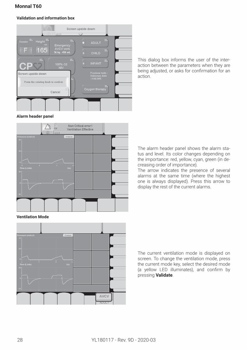
Validationandinformationbox
This dialog box informs the user of the inter-action between the parameters when they are beingadjusted,orasksforconfirmationforanaction.
Alarmheaderpanel
The alarm header panel shows the alarm sta-tus and level. Its color changes depending on the importance: red, yellow, cyan, green (in de-creasing order of importance).The arrow indicates the presence of several alarms at the same time (where the highest one is always displayed). Press this arrow to display the rest of the current alarms.
VentilationMode
The current ventilation mode is displayed on screen. To change the ventilation mode, press the current mode key, select the desired mode (a yellow LED illuminates), and confirm bypressing Validate.
Use
29YL180117 - Rev. 9D - 2020-03
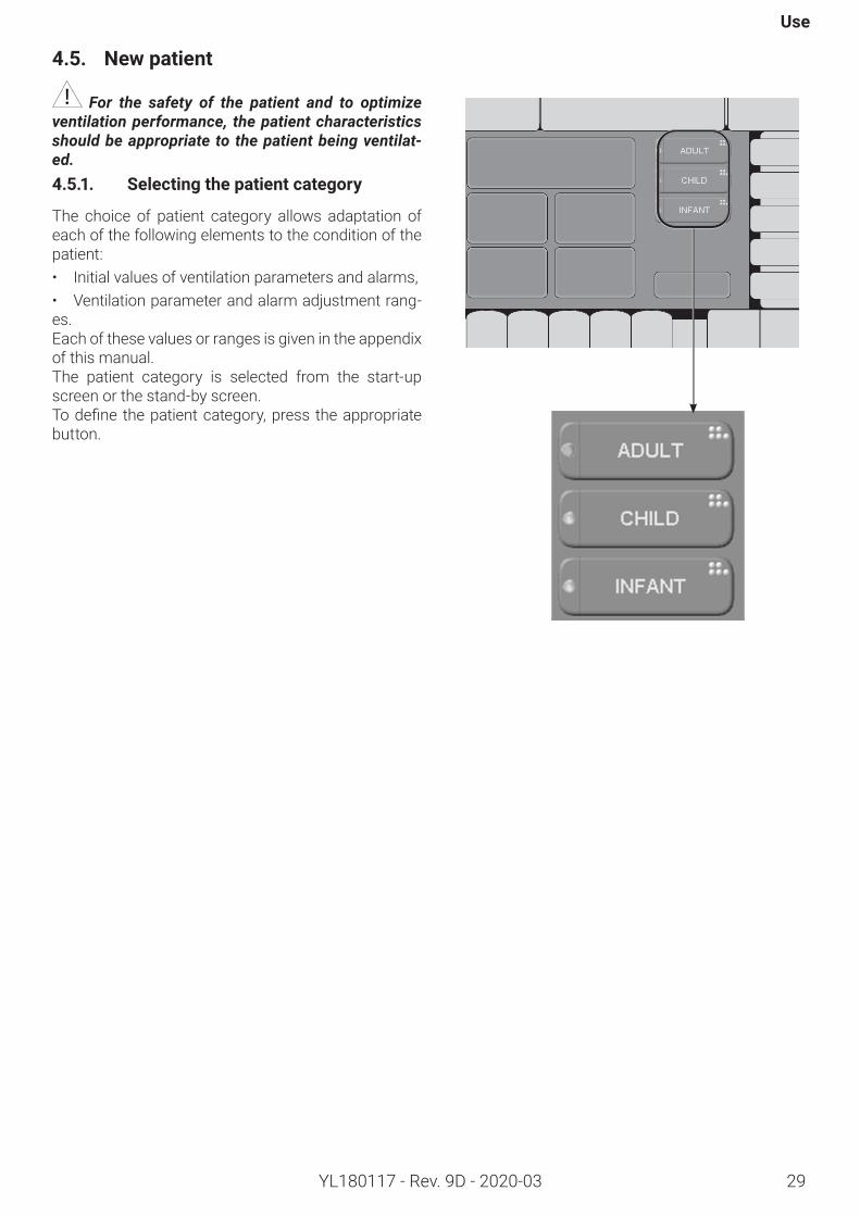
4.5. Newpatient
For the safety of the patient and to optimize ventilation performance, the patient characteristics should be appropriate to the patient being ventilat-ed. 4.5.1. Selectingthepatientcategory
The choice of patient category allows adaptation of each of the following elements to the condition of the patient:• Initial values of ventilation parameters and alarms,• Ventilation parameter and alarm adjustment rang-es. Each of these values or ranges is given in the appendix of this manual.The patient category is selected from the start-up screen or the stand-by screen.Todefinethepatientcategory,press theappropriatebutton.
Monnal T60
30 YL180117 - Rev. 9D - 2020-03
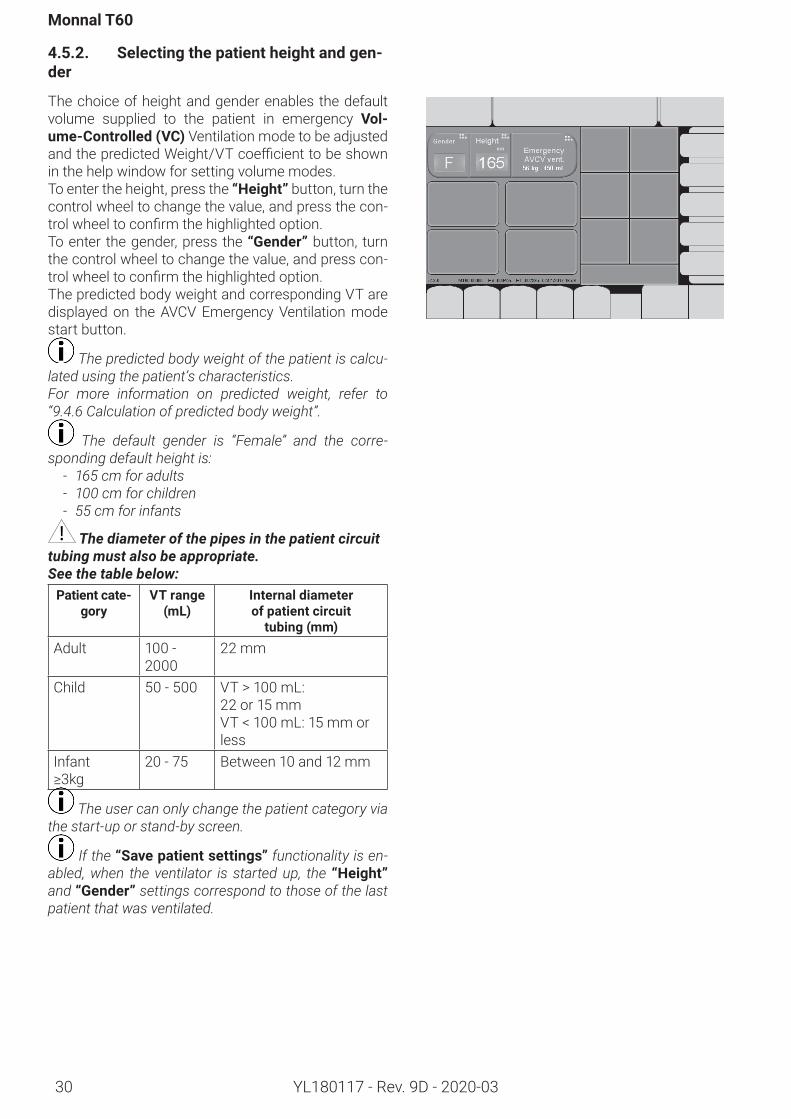
4.5.2. Selectingthepatientheightandgen-der
The choice of height and gender enables the default volume supplied to the patient in emergency Vol-ume-Controlled(VC) Ventilation mode to be adjusted andthepredictedWeight/VTcoefficienttobeshownin the help window for setting volume modes.To enter the height, press the “Height” button, turn the control wheel to change the value, and press the con-trolwheeltoconfirmthehighlightedoption.To enter the gender, press the “Gender” button, turn the control wheel to change the value, and press con-trolwheeltoconfirmthehighlightedoption.The predicted body weight and corresponding VT are displayed on the AVCV Emergency Ventilation mode start button.
The predicted body weight of the patient is calcu-lated using the patient’s characteristics.For more information on predicted weight, refer to “9.4.6 Calculation of predicted body weight”.
The default gender is “Female” and the corre-sponding default height is:
- 165 cm for adults- 100 cm for children- 55 cm for infants
The diameter of the pipes in the patient circuit tubing must also be appropriate.See the table below:Patientcate-
goryVTrange
(mL)Internaldiameter ofpatientcircuit tubing(mm)
Adult 100 - 2000
22 mm
Child 50 - 500 VT > 100 mL: 22 or 15 mmVT < 100 mL: 15 mm or less
Infant ≥3kg
20 - 75 Between 10 and 12 mm
The user can only change the patient category via the start-up or stand-by screen.
If the “Savepatientsettings” functionality is en-abled, when the ventilator is started up, the “Height” and “Gender” settings correspond to those of the last patient that was ventilated.
Use
31YL180117 - Rev. 9D - 2020-03
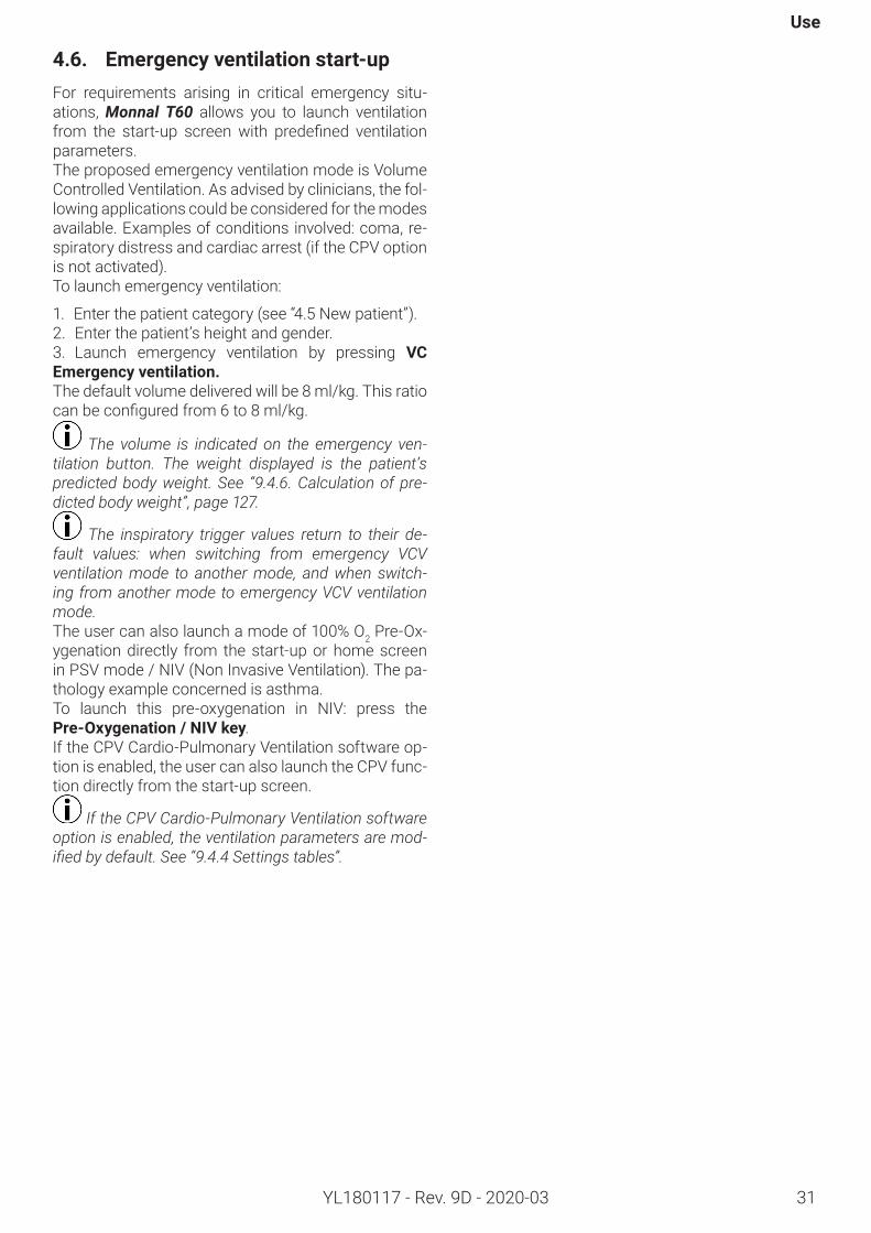
4.6. Emergencyventilationstart-upFor requirements arising in critical emergency situ-ations, Monnal T60 allows you to launch ventilation from the start-up screen with predefined ventilationparameters.The proposed emergency ventilation mode is Volume Controlled Ventilation. As advised by clinicians, the fol-lowing applications could be considered for the modes available. Examples of conditions involved: coma, re-spiratory distress and cardiac arrest (if the CPV option is not activated).To launch emergency ventilation:
1. Enter the patient category (see “4.5 New patient”).2. Enter the patient’s height and gender.3. Launch emergency ventilation by pressing VC Emergencyventilation.The default volume delivered will be 8 ml/kg. This ratio canbeconfiguredfrom6to8ml/kg.
The volume is indicated on the emergency ven-tilation button. The weight displayed is the patient’s predicted body weight. See “9.4.6. Calculation of pre-dicted body weight”, page 127.
The inspiratory trigger values return to their de-fault values: when switching from emergency VCV ventilation mode to another mode, and when switch-ing from another mode to emergency VCV ventilation mode.The user can also launch a mode of 100% O2 Pre-Ox-ygenation directly from the start-up or home screen in PSV mode / NIV (Non Invasive Ventilation). The pa-thology example concerned is asthma.To launch this pre-oxygenation in NIV: press the Pre-Oxygenation/NIVkey.If the CPV Cardio-Pulmonary Ventilation software op-tion is enabled, the user can also launch the CPV func-tion directly from the start-up screen.
If the CPV Cardio-Pulmonary Ventilation software option is enabled, the ventilation parameters are mod-ified by default. See “9.4.4 Settings tables”.
Monnal T60
32 YL180117 - Rev. 9D - 2020-03
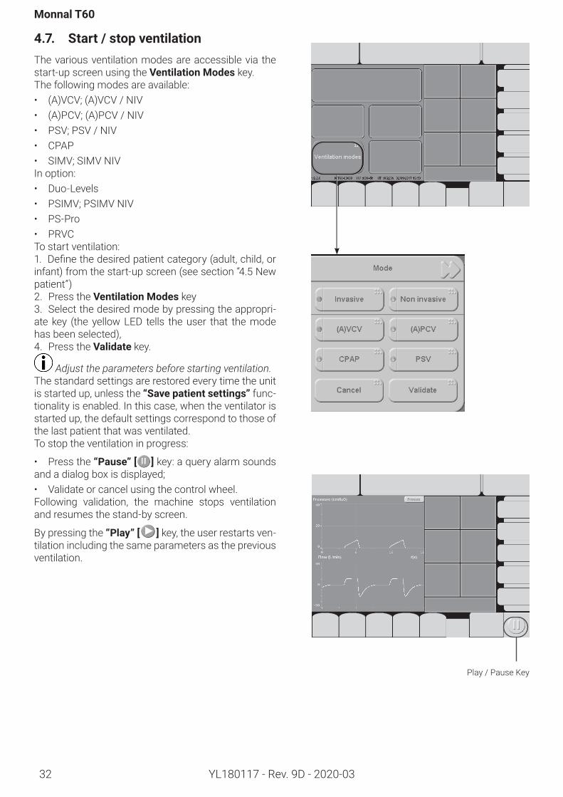
4.7. Start/stopventilationThe various ventilation modes are accessible via the start-up screen using the VentilationModes key.The following modes are available:• (A)VCV; (A)VCV / NIV• (A)PCV; (A)PCV / NIV • PSV; PSV / NIV• CPAP• SIMV; SIMV NIVIn option:• Duo-Levels• PSIMV; PSIMV NIV• PS-Pro• PRVCTo start ventilation:1. Definethedesiredpatientcategory(adult,child,orinfant) from the start-up screen (see section “4.5 New patient”)2. Press the VentilationModes key3. Select the desired mode by pressing the appropri-ate key (the yellow LED tells the user that the mode has been selected),4. Press the Validate key.
Adjust the parameters before starting ventilation.The standard settings are restored every time the unit is started up, unless the “Savepatientsettings” func-tionality is enabled. In this case, when the ventilator is started up, the default settings correspond to those of the last patient that was ventilated. To stop the ventilation in progress:
• Press the “Pause” [ ]key: a query alarm sounds and a dialog box is displayed;• Validate or cancel using the control wheel.Following validation, the machine stops ventilation and resumes the stand-by screen.
By pressing the “Play” [ ] key, the user restarts ven-tilation including the same parameters as the previous ventilation.
Play / Pause Key
Use
33YL180117 - Rev. 9D - 2020-03
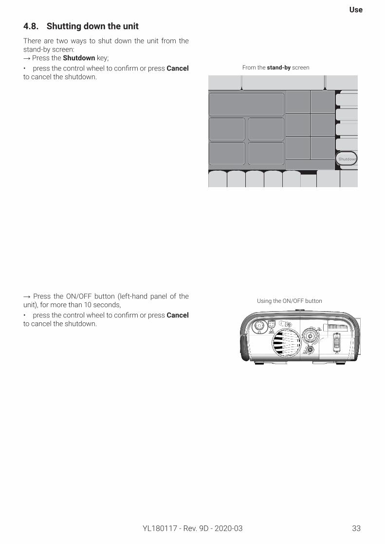
4.8. ShuttingdowntheunitThere are two ways to shut down the unit from the stand-by screen:→ Press the Shutdown key;• pressthecontrolwheeltoconfirmorpressCancel to cancel the shutdown.
→ Press the ON/OFF button (left-hand panel of the unit), for more than 10 seconds,• pressthecontrolwheeltoconfirmorpressCancel to cancel the shutdown.
Using the ON/OFF button
From thestand-by screen
Monnal T60
34 YL180117 - Rev. 9D - 2020-03
4.9. Ventilationmodes
4.9.1. Modeselection
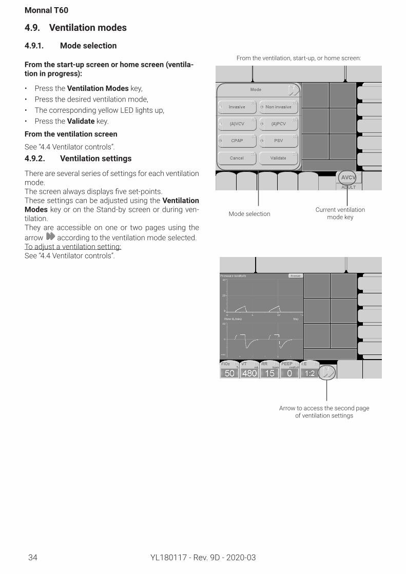
Fromthestart-upscreenorhomescreen(ventila-tioninprogress):
• Press the VentilationModes key,• Press the desired ventilation mode,• The corresponding yellow LED lights up,• Press the Validate key.
Fromtheventilationscreen
See “4.4 Ventilator controls”.4.9.2. Ventilationsettings
There are several series of settings for each ventilation mode.Thescreenalwaysdisplaysfiveset-points.These settings can be adjusted using the VentilationModes key or on the Stand-by screen or during ven-tilation. They are accessible on one or two pages using the arrow according to the ventilation mode selected.To adjust a ventilation setting:See “4.4 Ventilator controls”.
From the ventilation, start-up, or home screen:
Mode selectionCurrent ventilation
mode key
Arrow to access the second page of ventilation settings
Use
35YL180117 - Rev. 9D - 2020-03
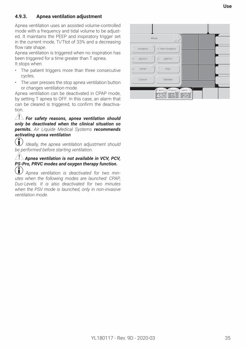
4.9.3. Apneaventilationadjustment
Apnea ventilation uses an assisted volume-controlled mode with a frequency and tidal volume to be adjust-ed. It maintains the PEEP and inspiratory trigger set in the current mode, Ti/Ttot of 33% and a decreasing flowrateshape.Apnea ventilation is triggered when no inspiration has been triggered for a time greater than T apnea.It stops when:• The patient triggers more than three consecutive
cycles,• The user presses the stop apnea ventilation button
or changes ventilation mode.Apnea ventilation can be deactivated in CPAP mode, by setting T apnea to OFF. In this case, an alarm that canbecleared is triggered, to confirm thedeactiva-tion.
For safety reasons, apnea ventilation should only be deactivated when the clinical situation so permits. Air Liquide Medical Systems recommends activating apnea ventilation
Ideally, the apnea ventilation adjustment should be performed before starting ventilation.
Apnea ventilation is not available in VCV, PCV, PS-Pro, PRVC modes and oxygen therapy function.
Apnea ventilation is deactivated for two min-utes when the following modes are launched: CPAP, Duo-Levels. It is also deactivated for two minutes when the PSV mode is launched, only in non-invasive ventilation mode.
Monnal T60
36 YL180117 - Rev. 9D - 2020-03
4.9.4. VCV(controlledventilationorassistedvolume-controlledventilation)
[VCV=Volume-ControlledVentilation]
Principle
VCV mode is used to control the tidal volume delivered to the patient on inspiration and the frequency of the ventilation cycles. During expiration, the ventilator regulates the pressure in order to maintain the set PEEP level. If the inspiratory trigger value is set, this mode denotes (A) to show that it is now also assisted.The respiratory frequency can be increased as soon as the ventilator detects that the patient is making a respi-ratory effort
Set-pointsFiO2 inspired oxygen fractionVT tidal volume (mL)
RR minimum respiratory frequency (bpm)
PEEP positive end of expiration pressureI:E ratio of inspiration time to expiration timeTrig.I inspiratory trigger (L/min)Tplat adjustment of inspiratory plateau time (% TI)Flow shape formofflowrateinsufflatedtothepatient:Constantordecelerated
VTsigh enablingthesighfunctionif≠OFFsighamplitude(unitxVT;e.g.VTsigh=1.5VT)
Sigh sigh periodicity (1 sigh every x cycles)
In VCV, there is no apnea ventilation (or “backup ventilation”).Safety is guaranteed by setting the lower limit on the frequency and tidal volume according to each patient category.
Use
37YL180117 - Rev. 9D - 2020-03
4.9.5. PCV(controlledventilationorassist-edpressure-controlledventilation)
[PCV=Pressure-ControlledVentilation]
Principle
PCV mode is used to control the pressure delivered to the patient, the inspiration time, and the frequency of the ventilation cycles. During expiration, the ventila-tor regulates the pressure in order to maintain the set PEEP level. If the inspiratory trigger value is set, this mode denotes (A) to show that it is now also assisted.The respiratory frequency can be increased as soon as the ventilator detects that the patient is making a respiratory effort.
Set-pointsFiO2 inspired oxygen fraction PI inspiratory pressure (cmH2O)RR minimum respiratory frequency (bpm)
PEEP positive end of expiration pressure (cmH2O)
I:E ratio of inspiration time to expiration time
Trig.I inspiratory trigger (L/min)Slope inspiratory pressure slope (cmH2O/s)
Plsighenablingthesighfunctionif≠OFFpressure supplied during a sigh (unit x PI;e.g.:PIsigh=1.4PI)
Sigh sigh periodicity (1 sigh every x cycles)
The PI value corresponds to the total inspiratory pressure applied to the patient. The PEEP value is in-corporated in the PI.In PCV mode, unlike VCV, the pressure delivered to the patient is controlled but the tidal and minute volumes are not.
Monnal T60
YL180117 - Rev. 9D - 2020-0338
4.9.6. PSV(spontaneousventilationwithinspiratoryassistanceandPEEP)
[PSV=PressureSupportVentilation]
Principle
A constant positive pressure is maintained above PEEP level in the patient circuit for each inspiratory effort. The switch to the expiratory phase can be triggered:• Iftheflowratefallsbelowthesetexpiratorythreshold(Trig.E);• By an expiratory effort from the patient,• Ifthemaximumsetinsufflationtimeisreached(TImax).If there is no inspiratory effort, the ventilator provides the minimum set frequency.
Set-pointsFiO2 inspired oxygen fraction PSV pressure support ventilation (cmH2O)
RR mini minimum respiratory frequency (bpm) (if the function is enabled)
PEEP positive end of expiration pressure (cmH2O)Trig.I inspiratory trigger (L/min)TImax maximum inspiration time of cycles (s)Slope pressure support pressure rise slope (cmH2O/s)Trig.E expiratorytrigger(%ofpeakinspiratoryflow).
Apnea ventilation can be activated; the apnea parameters should be suited to the condition and require-ments of the patient.- Use of the ‘RR min’ parameter: in the absence of inspiratory demand for a time exceeding ‘1/RR minimum’ of a minute. The ventilator initiates a pressure support cycle. The RR low alarm can be associated with this safety feature by setting it to a value above RR min. - Use of the ‘TI max’ parameter: in the event of a leak in the circuit, the flow rate expiratory trigger may not be activated; in this case, the limitation on inspiration time allows the patient to enter the expiratory phase.
When this mode is launched during non-invasive ventilation, apnea ventilation is deactivated for two min-utes.
Use
YL180117 - Rev. 9D - 2020-03 39
4.9.7. SIMV
[SIMV=SynchronizedIntermittentMandatoryVentilation]
Principle
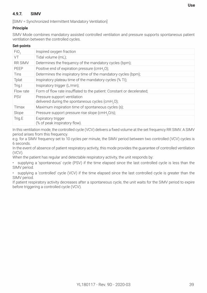
SIMV Mode combines mandatory assisted controlled ventilation and pressure supports spontaneous patient ventilation between the controlled cycles.
Set-pointsFiO2 Inspired oxygen fraction VT Tidal volume (mL);RR SIMV Determines the frequency of the mandatory cycles (bpm);PEEP Positive end of expiration pressure (cmH2O);Tins Determines the inspiratory time of the mandatory cycles (bpm);Tplat Inspiratory plateau time of the mandatory cycles (% TI);Trig.I Inspiratory trigger (L/min);Flow rate Formofflowrateinsufflatedtothepatient:Constantordecelerated;PSV Pressure support ventilation
delivered during the spontaneous cycles (cmH2O);TImax Maximum inspiration time of spontaneous cycles (s);Slope Pressure support pressure rise slope (cmH2O/s);Trig.E Expiratory trigger
(%ofpeakinspiratoryflow).
Inthisventilationmode,thecontrolledcycle(VCV)deliversafixedvolumeatthesetfrequencyRRSIMV.ASIMVperiod arises from this frequency.e.g. for a SIMV frequency set to 10 cycles per minute, the SIMV period between two controlled (VCV) cycles is 6 seconds.In the event of absence of patient respiratory activity, this mode provides the guarantee of controlled ventilation (VCV).When the patient has regular and detectable respiratory activity, the unit responds by:• supplying a ‘spontaneous’ cycle (PSV) if the time elapsed since the last controlled cycle is less than the SIMV period. • supplying a ‘controlled’ cycle (VCV) if the time elapsed since the last controlled cycle is greater than the SIMV period.If patient respiratory activity decreases after a spontaneous cycle, the unit waits for the SIMV period to expire before triggering a controlled cycle (VCV).
Monnal T60
YL180117 - Rev. 9D - 2020-0340
4.9.8. PSV/NIV(non-invasiveventilation)
[NIV=NonInvasiveVentilation]
Principle
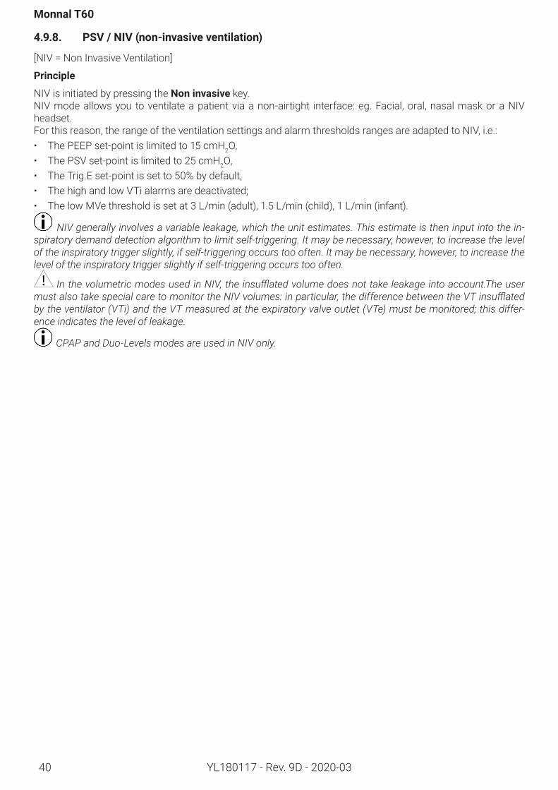
NIV is initiated by pressing the Noninvasive key. NIV mode allows you to ventilate a patient via a non-airtight interface: eg. Facial, oral, nasal mask or a NIV headset.For this reason, the range of the ventilation settings and alarm thresholds ranges are adapted to NIV, i.e.:• The PEEP set-point is limited to 15 cmH2O,• The PSV set-point is limited to 25 cmH2O,• The Trig.E set-point is set to 50% by default,• The high and low VTi alarms are deactivated; • The low MVe threshold is set at 3 L/min (adult), 1.5 L/min (child), 1 L/min (infant).
NIV generally involves a variable leakage, which the unit estimates. This estimate is then input into the in-spiratory demand detection algorithm to limit self-triggering. It may be necessary, however, to increase the level of the inspiratory trigger slightly, if self-triggering occurs too often. It may be necessary, however, to increase the level of the inspiratory trigger slightly if self-triggering occurs too often.
In the volumetric modes used in NIV, the insufflated volume does not take leakage into account.The user must also take special care to monitor the NIV volumes: in particular, the difference between the VT insufflated by the ventilator (VTi) and the VT measured at the expiratory valve outlet (VTe) must be monitored; this differ-ence indicates the level of leakage.
CPAP and Duo-Levels modes are used in NIV only.
Use
41YL180117 - Rev. 9D - 2020-03
4.9.9. CPAP(ContinuousPositiveAirwayPressure)
[Continuouspositiveairwaypressure]
Principle
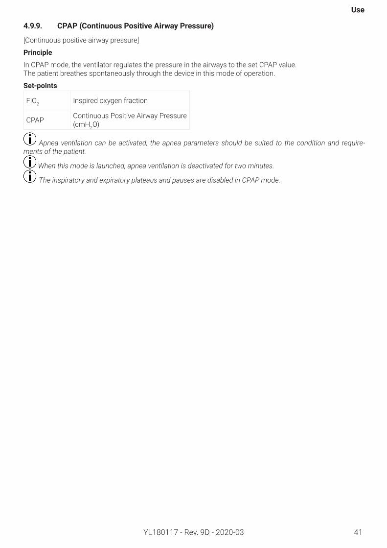
In CPAP mode, the ventilator regulates the pressure in the airways to the set CPAP value. The patient breathes spontaneously through the device in this mode of operation.
Set-points
FiO2 Inspired oxygen fraction
CPAP Continuous Positive Airway Pressure (cmH2O)
Apnea ventilation can be activated; the apnea parameters should be suited to the condition and require-ments of the patient.
When this mode is launched, apnea ventilation is deactivated for two minutes.
The inspiratory and expiratory plateaus and pauses are disabled in CPAP mode.
Monnal T60
42 YL180117 - Rev. 9D - 2020-03
4.9.10. Duo-Levels(AlternationoftwoCPAPlevels)
Principle
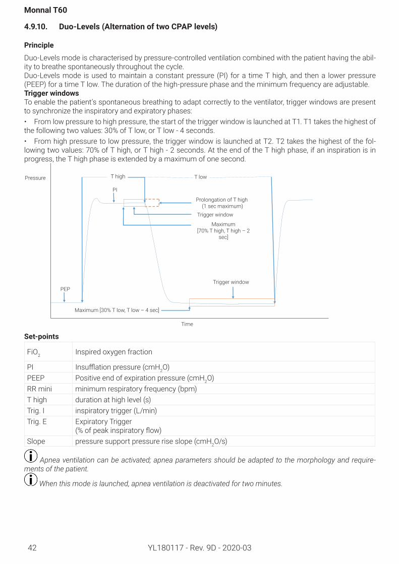
Duo-Levels mode is characterised by pressure-controlled ventilation combined with the patient having the abil-ity to breathe spontaneously throughout the cycle.Duo-Levels mode is used to maintain a constant pressure (PI) for a time T high, and then a lower pressure (PEEP) for a time T low. The duration of the high-pressure phase and the minimum frequency are adjustable. TriggerwindowsTo enable the patient’s spontaneous breathing to adapt correctly to the ventilator, trigger windows are present to synchronize the inspiratory and expiratory phases:• From low pressure to high pressure, the start of the trigger window is launched at T1. T1 takes the highest of the following two values: 30% of T low, or T low - 4 seconds.• From high pressure to low pressure, the trigger window is launched at T2. T2 takes the highest of the fol-lowing two values: 70% of T high, or T high - 2 seconds. At the end of the T high phase, if an inspiration is in progress, the T high phase is extended by a maximum of one second.
Pressure T high
PI
Prolongation of T high (1 sec maximum)
Trigger window
Maximum [70% T high, T high – 2
sec]
PEPTrigger window
Maximum[30%Tlow,Tlow–4sec]
T low
Time
Set-points
FiO2 Inspired oxygen fraction
PI Insufflationpressure(cmH2O)PEEP Positive end of expiration pressure (cmH2O)RR mini minimum respiratory frequency (bpm)T high duration at high level (s)Trig. I inspiratory trigger (L/min)Trig. E Expiratory Trigger
(%ofpeakinspiratoryflow)Slope pressure support pressure rise slope (cmH2O/s)
Apnea ventilation can be activated; apnea parameters should be adapted to the morphology and require-ments of the patient.
When this mode is launched, apnea ventilation is deactivated for two minutes.
Use
YL180117 - Rev. 9D - 2020-03 43
4.9.11. PRVC(Pressure-RegulatedVolumeControlled)
Principle
PRVC mode is a pressure-regulated ventilation mode that guarantees the volume delivered to the patient. The ventilator automatically adapts the inspiratory pressure delivered so that the monitored Vti is equal to the set VT Target. The adaptation interval of the PI is between 0.1 cmH2O and 3 cmH2O. It depends on the gap between the VT Target and the moniored Vti
It is possible to activate or disable the set VT Target:- When the VT Target is activated, the PI delivered to the patient is between the PEEP + 5 cmH2O and the PI max. - The set PI then indicates Auto.- When the VT Target is OFF, the delivered PI is the set PI. The mode is then equivalent to PCV mode.- If the VT Target is disabled during ventilation, the set pressure takes the current regulation value.Whatever the circumstances, the delivered PI should never exceed the PI Max.
The “VT target and regulated pressure incompatibility!!!” alarm is activated when:- Monitored volume < 90% of the VT Target and delivered PI = PI Max- Monitored volume > 110% of the VT Target and delivered PI = PEEP + 5 cmH2O- Furthermore if the Ppeak, Vti Max or patient disconnection alarm is set off, the adaptation of the PI is inhibited until the alarm stops.
Set-pointsFiO2 inspired oxygen fraction (%)VT Target volume target (mL);RR minimum respiratory frequency (bpm)PEEP positive end of expiration pressure
(cmH2O)
I:E ratio of inspiration time to expiration time
PI inspiratory pressure (cmH2O) PI max maximum inspiratory pressure (cm-
H2O)I.Trig inspiratory trigger (L/min or cmH2O)Slope inspiratory pressure slope (cmH2O/s)
The VT Target should not be used in NIV. If there is a leak, the tidal volume monitored by the ventilator no longer represents the tidal volume inhaled by the patient. Any adaptation of the pressure is therefore inappropriate.
In PRVC mode, there is no apnea ventilation (or backup ventilation).
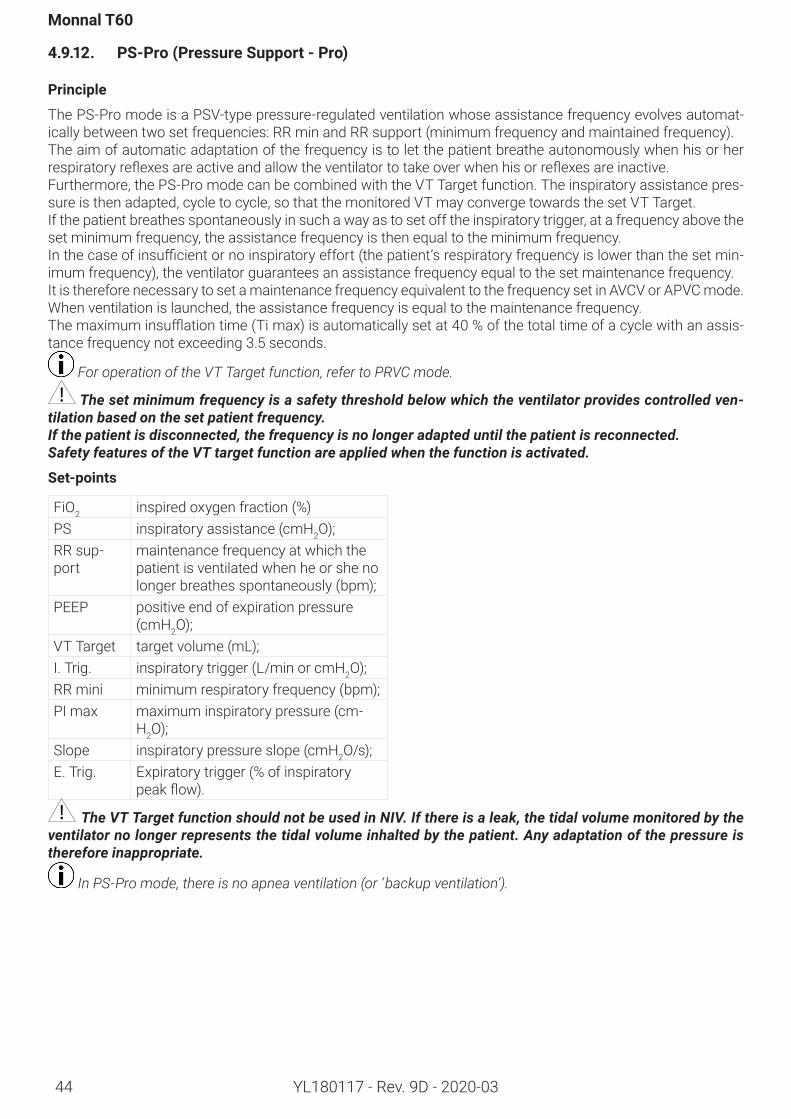
Monnal T60
YL180117 - Rev. 9D - 2020-0344
4.9.12. PS-Pro(PressureSupport-Pro)
Principle
The PS-Pro mode is a PSV-type pressure-regulated ventilation whose assistance frequency evolves automat-ically between two set frequencies: RR min and RR support (minimum frequency and maintained frequency). The aim of automatic adaptation of the frequency is to let the patient breathe autonomously when his or her respiratoryreflexesareactiveandallowtheventilatortotakeoverwhenhisorreflexesareinactive.Furthermore, the PS-Pro mode can be combined with the VT Target function. The inspiratory assistance pres-sure is then adapted, cycle to cycle, so that the monitored VT may converge towards the set VT Target.If the patient breathes spontaneously in such a way as to set off the inspiratory trigger, at a frequency above the set minimum frequency, the assistance frequency is then equal to the minimum frequency.Inthecaseofinsufficientornoinspiratoryeffort(thepatient’srespiratoryfrequencyislowerthanthesetmin-imum frequency), the ventilator guarantees an assistance frequency equal to the set maintenance frequency. It is therefore necessary to set a maintenance frequency equivalent to the frequency set in AVCV or APVC mode.When ventilation is launched, the assistance frequency is equal to the maintenance frequency.Themaximuminsufflationtime(Timax)isautomaticallysetat40%ofthetotaltimeofacyclewithanassis-tance frequency not exceeding 3.5 seconds.
For operation of the VT Target function, refer to PRVC mode.
The set minimum frequency is a safety threshold below which the ventilator provides controlled ven-tilation based on the set patient frequency.If the patient is disconnected, the frequency is no longer adapted until the patient is reconnected.Safety features of the VT target function are applied when the function is activated.
Set-points
FiO2 inspired oxygen fraction (%)PS inspiratory assistance (cmH2O);RR sup-port
maintenance frequency at which the patient is ventilated when he or she no longer breathes spontaneously (bpm);
PEEP positive end of expiration pressure (cmH2O);
VT Target target volume (mL);I. Trig. inspiratory trigger (L/min or cmH2O);RR mini minimum respiratory frequency (bpm);PI max maximum inspiratory pressure (cm-
H2O);Slope inspiratory pressure slope (cmH2O/s);E. Trig. Expiratory trigger (% of inspiratory
peakflow).
The VT Target function should not be used in NIV. If there is a leak, the tidal volume monitored by the ventilator no longer represents the tidal volume inhalted by the patient. Any adaptation of the pressure is therefore inappropriate.
In PS-Pro mode, there is no apnea ventilation (or ‘backup ventilation’).
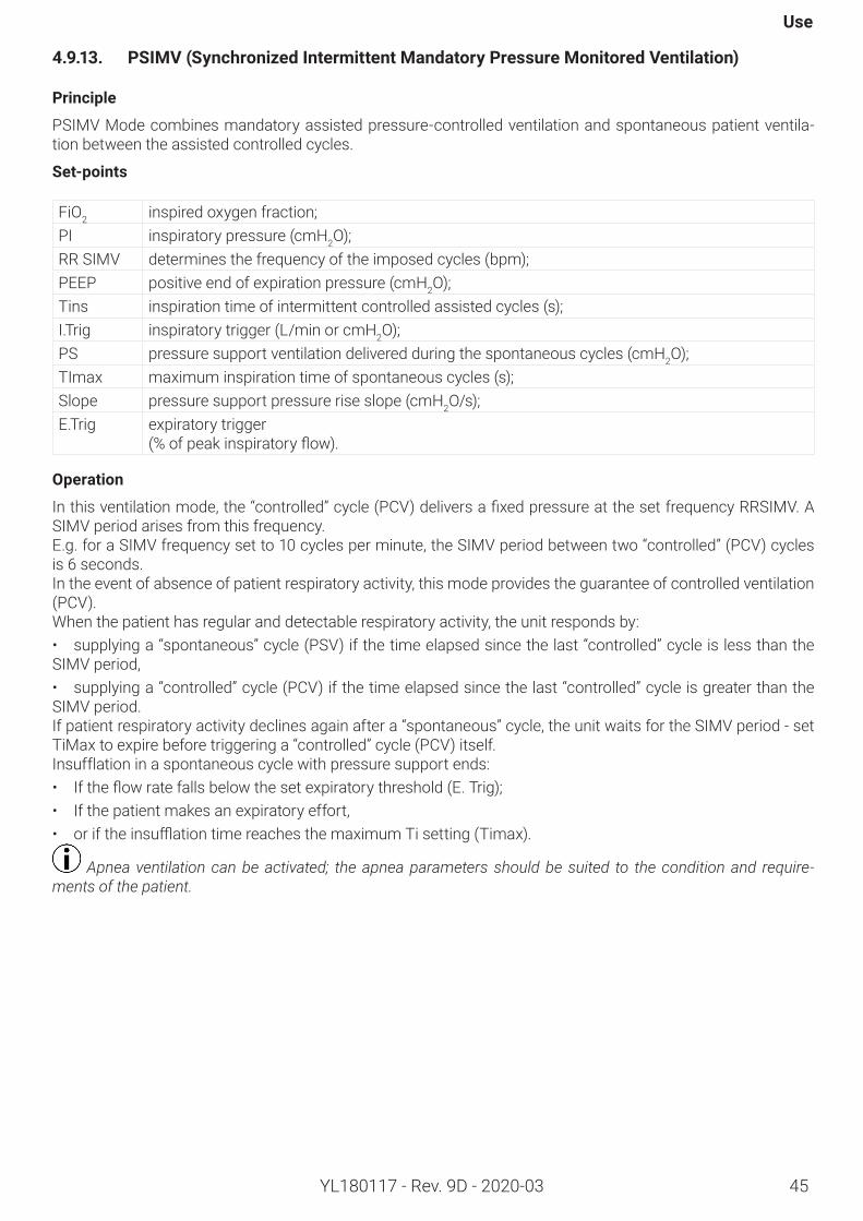
Use
YL180117 - Rev. 9D - 2020-03 45
4.9.13. PSIMV(SynchronizedIntermittentMandatoryPressureMonitoredVentilation)
Principle
PSIMV Mode combines mandatory assisted pressure-controlled ventilation and spontaneous patient ventila-tion between the assisted controlled cycles.
Set-points
FiO2 inspired oxygen fraction;PI inspiratory pressure (cmH2O);RR SIMV determines the frequency of the imposed cycles (bpm);PEEP positive end of expiration pressure (cmH2O);Tins inspiration time of intermittent controlled assisted cycles (s);I.Trig inspiratory trigger (L/min or cmH2O);PS pressure support ventilation delivered during the spontaneous cycles (cmH2O);TImax maximum inspiration time of spontaneous cycles (s);Slope pressure support pressure rise slope (cmH2O/s);E.Trig expiratory trigger
(%ofpeakinspiratoryflow).
Operation
Inthisventilationmode,the“controlled”cycle(PCV)deliversafixedpressureatthesetfrequencyRRSIMV.ASIMV period arises from this frequency.E.g. for a SIMV frequency set to 10 cycles per minute, the SIMV period between two “controlled” (PCV) cycles is 6 seconds.In the event of absence of patient respiratory activity, this mode provides the guarantee of controlled ventilation (PCV).When the patient has regular and detectable respiratory activity, the unit responds by:• supplying a “spontaneous” cycle (PSV) if the time elapsed since the last “controlled” cycle is less than the SIMV period,• supplying a “controlled” cycle (PCV) if the time elapsed since the last “controlled” cycle is greater than the SIMV period.If patient respiratory activity declines again after a “spontaneous” cycle, the unit waits for the SIMV period - set TiMax to expire before triggering a “controlled” cycle (PCV) itself.Insufflation in a spontaneous cycle with pressure support ends: • Iftheflowratefallsbelowthesetexpiratorythreshold(E.Trig);• If the patient makes an expiratory effort,• oriftheinsufflationtimereachesthemaximumTisetting(Timax).
Apnea ventilation can be activated; the apnea parameters should be suited to the condition and require-ments of the patient.
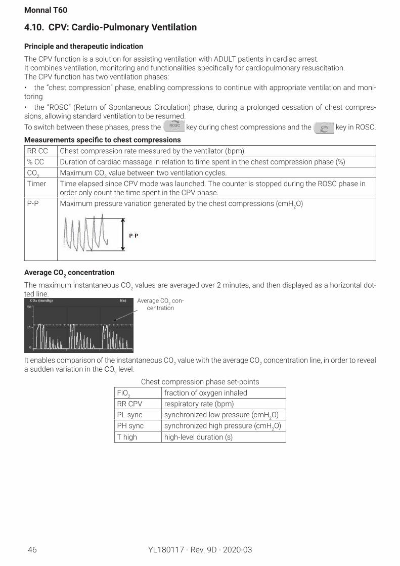
Monnal T60
YL180117 - Rev. 9D - 2020-0346
4.10. CPV:Cardio-PulmonaryVentilation
Principleandtherapeuticindication
The CPV function is a solution for assisting ventilation with ADULT patients in cardiac arrest.Itcombinesventilation,monitoringandfunctionalitiesspecificallyforcardiopulmonaryresuscitation.The CPV function has two ventilation phases: • the “chest compression” phase, enabling compressions to continue with appropriate ventilation and moni-toring• the “ROSC” (Return of Spontaneous Circulation) phase, during a prolonged cessation of chest compres-sions, allowing standard ventilation to be resumed.To switch between these phases, press the key during chest compressions and the key in ROSC.
MeasurementsspecifictochestcompressionsRR CC Chest compression rate measured by the ventilator (bpm)% CC Duration of cardiac massage in relation to time spent in the chest compression phase (%)CO2 Maximum CO2 value between two ventilation cycles.Timer Time elapsed since CPV mode was launched. The counter is stopped during the ROSC phase in
order only count the time spent in the CPV phase.P-P Maximum pressure variation generated by the chest compressions (cmH2O)
AverageCO2concentration
The maximum instantaneous CO2 values are averaged over 2 minutes, and then displayed as a horizontal dot-ted line.
Average CO2 con-centration
It enables comparison of the instantaneous CO2 value with the average CO2 concentration line, in order to reveal a sudden variation in the CO2 level.
Chest compression phase set-points FiO2 fraction of oxygen inhaledRR CPV respiratory rate (bpm)PL sync synchronized low pressure (cmH2O)PH sync synchronized high pressure (cmH2O)T high high-level duration (s)
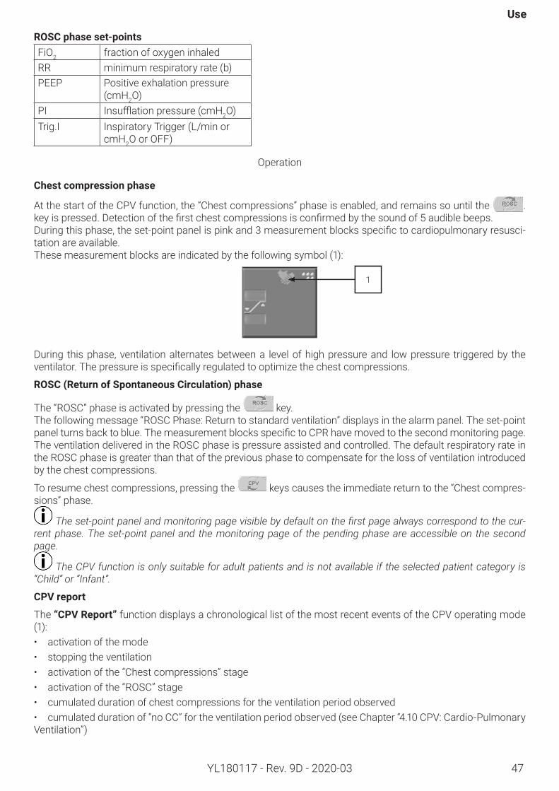
Use
47YL180117 - Rev. 9D - 2020-03
ROSCphaseset-pointsFiO2 fraction of oxygen inhaledRR minimum respiratory rate (b)PEEP Positive exhalation pressure
(cmH2O)PI Insufflationpressure(cmH2O)Trig.I Inspiratory Trigger (L/min or
cmH2O or OFF)
Operation
Chestcompressionphase
At the start of the CPV function, the “Chest compressions” phase is enabled, and remains so until the . keyispressed.Detectionofthefirstchestcompressionsisconfirmedbythesoundof5audiblebeeps.Duringthisphase,theset-pointpanelispinkand3measurementblocksspecifictocardiopulmonaryresusci-tation are available. These measurement blocks are indicated by the following symbol (1):
During this phase, ventilation alternates between a level of high pressure and low pressure triggered by the ventilator.Thepressureisspecificallyregulatedtooptimizethechestcompressions.
ROSC(ReturnofSpontaneousCirculation)phase
The “ROSC” phase is activated by pressing the key.The following message “ROSC Phase: Return to standard ventilation” displays in the alarm panel. The set-point panelturnsbacktoblue.ThemeasurementblocksspecifictoCPRhavemovedtothesecondmonitoringpage.The ventilation delivered in the ROSC phase is pressure assisted and controlled. The default respiratory rate in the ROSC phase is greater than that of the previous phase to compensate for the loss of ventilation introduced by the chest compressions.
To resume chest compressions, pressing the keys causes the immediate return to the “Chest compres-sions” phase.
The set-point panel and monitoring page visible by default on the first page always correspond to the cur-rent phase. The set-point panel and the monitoring page of the pending phase are accessible on the second page.
The CPV function is only suitable for adult patients and is not available if the selected patient category is “Child” or “Infant”.
CPVreport
The “CPVReport” function displays a chronological list of the most recent events of the CPV operating mode (1):• activation of the mode• stopping the ventilation • activation of the “Chest compressions” stage• activation of the “ROSC” stage• cumulated duration of chest compressions for the ventilation period observed• cumulated duration of “no CC” for the ventilation period observed (see Chapter “4.10 CPV: Cardio-Pulmonary Ventilation”)
1
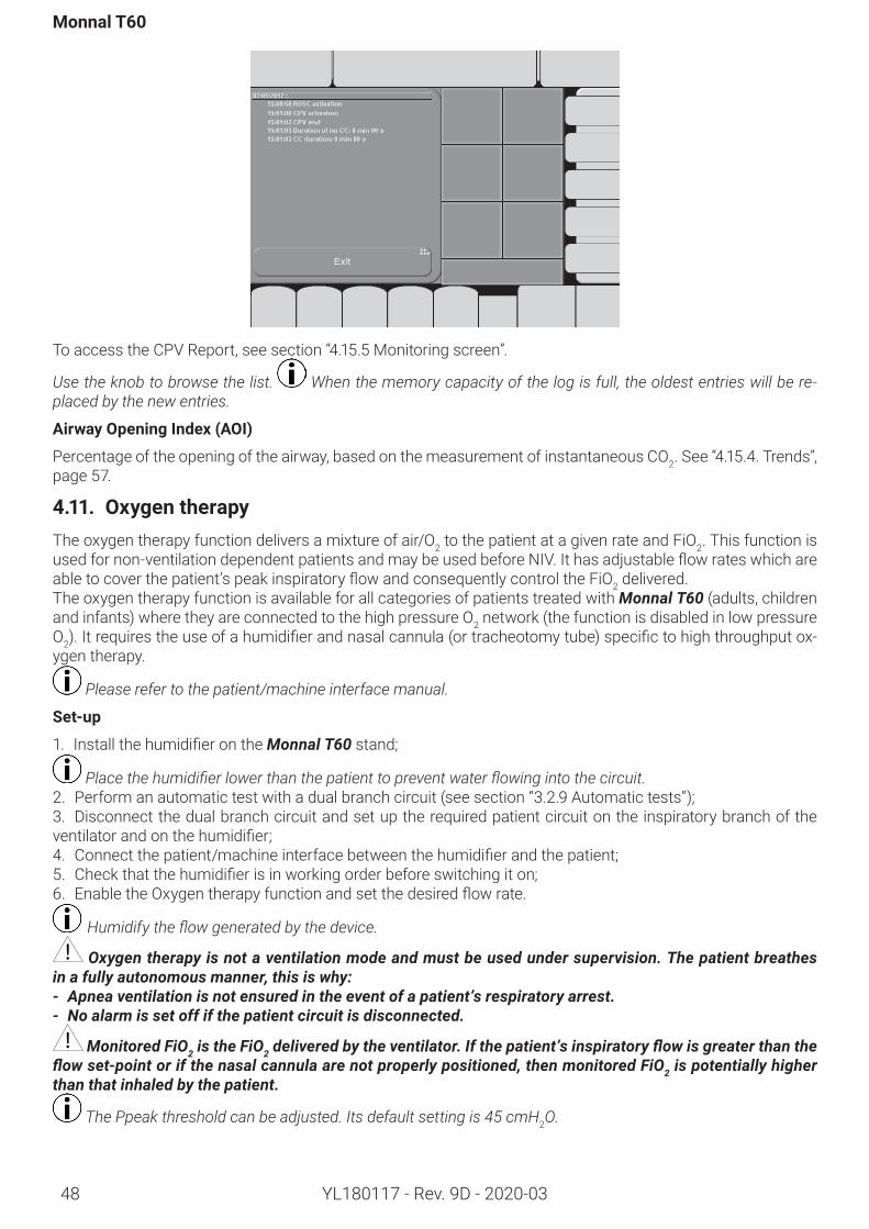
Monnal T60
YL180117 - Rev. 9D - 2020-0348
To access the CPV Report, see section “4.15.5 Monitoring screen”.
Use the knob to browse the list. When the memory capacity of the log is full, the oldest entries will be re-placed by the new entries.
AirwayOpeningIndex(AOI)
Percentage of the opening of the airway, based on the measurement of instantaneous CO2. See “4.15.4. Trends”, page 57.
4.11. OxygentherapyThe oxygen therapy function delivers a mixture of air/O2 to the patient at a given rate and FiO2. This function is usedfornon-ventilationdependentpatientsandmaybeusedbeforeNIV.Ithasadjustableflowrateswhichareabletocoverthepatient’speakinspiratoryflowandconsequentlycontroltheFiO2 delivered.The oxygen therapy function is available for all categories of patients treated with Monnal T60 (adults, children and infants) where they are connected to the high pressure O2 network (the function is disabled in low pressure O2).Itrequirestheuseofahumidifierandnasalcannula(ortracheotomytube)specifictohighthroughputox-ygen therapy.
Please refer to the patient/machine interface manual.
Set-up
1. InstallthehumidifierontheMonnal T60 stand;
Place the humidifier lower than the patient to prevent water flowing into the circuit.2. Perform an automatic test with a dual branch circuit (see section “3.2.9 Automatic tests”);3. Disconnect the dual branch circuit and set up the required patient circuit on the inspiratory branch of the ventilatorandonthehumidifier;4. Connectthepatient/machineinterfacebetweenthehumidifierandthepatient;5. Checkthatthehumidifierisinworkingorderbeforeswitchingiton;6. EnabletheOxygentherapyfunctionandsetthedesiredflowrate.
Humidify the flow generated by the device.
Oxygen therapy is not a ventilation mode and must be used under supervision. The patient breathes in a fully autonomous manner, this is why:- Apnea ventilation is not ensured in the event of a patient’s respiratory arrest.- No alarm is set off if the patient circuit is disconnected.
Monitored FiO2 is the FiO2 delivered by the ventilator. If the patient’s inspiratory flow is greater than the flow set-point or if the nasal cannula are not properly positioned, then monitored FiO2 is potentially higher than that inhaled by the patient.
The Ppeak threshold can be adjusted. Its default setting is 45 cmH2O.
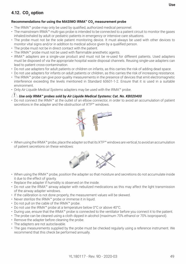
49
Use
YL180117 - Rev. 9D - 2020-03
4.12. CO2option
RecommendationsforusingtheMASIMOIRMA™CO2measurementprobe
• TheIRMA™probemayonlybeusedbyqualified,authorizedmedicalpersonnel.• The mainstream IRMA™ multi-gas probe is intended to be connected to a patient circuit to monitor the gases
inhaled/exhaled by adult or pediatric patients in emergency or intensive care situations.• The probe must not be the sole patient monitoring device. It must always be used with other devices to monitorvitalsignsand/orinadditiontomedicaladvicegivenbyaqualifiedperson.
• The probe must not be in direct contact with the patient. • TheIRMA™probemustnotbeusedwithflammableanestheticagents.• IRMA™ adapters are a single-use product and must not be re-used for different patients. Used adapters
must be disposed of via the appropriate hospital waste disposal channels. Reusing single-use adapters can lead to patient cross-contamination.
• Do not use adapters for adult patients or children on infants, as this carries the risk of adding dead space.• Do not use adapters for infants on adult patients or children, as this carries the risk of increasing resistance.• The IRMA™ probe can give poor-quality measurements in the presence of devices that emit electromagnetic
interference exceeding the levels mentioned in Standard 60601-1-2. Ensure that it is used in a suitable environment.
• Only Air Liquide Medical Systems adapters may be used with the IRMA™ probe.
Use only IRMA™ probes sold by Air Liquide Medical Systems: Cat. No. KB020400• Do not connect the IRMA™ at the outlet of an elbow connector, in order to avoid an accumulation of patient
secretions in the adapter and the obstruction of XTP™ windows.
• When using the IRMA™ probe, place the adapter so that its XTP™ windows are vertical, to avoid an accumulation of patient secretions on these windows:
• When using the IRMA™ probe, position the adapter so that moisture and secretions do not accumulate inside it due to the effect of gravity.
• Replace the adapter if humidity is observed on the inside.• Do not use the IRMA™ airway adapter with nebulized medications as this may affect the light transmission
of the airway adapter windows. • If the calibration is not done properly, the measurement values will be skewed.• Never sterilize the IRMA™ probe or immerse it in liquid.• Do not pull on the cable of the IRMA™ probe.• Do not use the IRMA™ probe at a temperature below 0°C or above 40°C.• During use, ensure that the IRMA™ probe is connected to the ventilator before you connect it to the patient.• The probe can be cleaned using a cloth dipped in alcohol (maximum 70% ethanol or 70% isopropanol).• Remove the adapter before cleaning the probe.• The adapters are not autoclavable.• The gas measurements supplied by the probe must be checked regularly using a reference instrument. We
recommend that this check be performed annually.
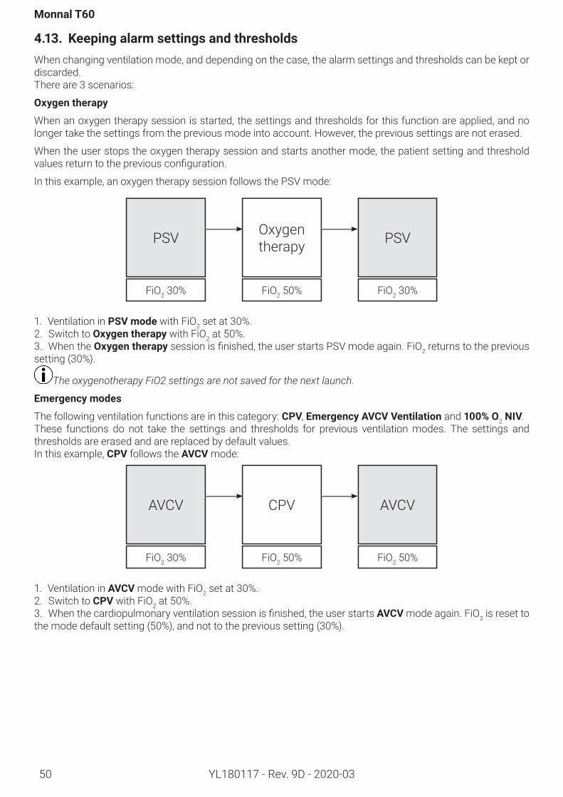
50
Monnal T60
YL180117 - Rev. 9D - 2020-03
4.13. KeepingalarmsettingsandthresholdsWhen changing ventilation mode, and depending on the case, the alarm settings and thresholds can be kept or discarded.There are 3 scenarios:
Oxygentherapy
When an oxygen therapy session is started, the settings and thresholds for this function are applied, and no longer take the settings from the previous mode into account. However, the previous settings are not erased.
When the user stops the oxygen therapy session and starts another mode, the patient setting and threshold valuesreturntothepreviousconfiguration.
In this example, an oxygen therapy session follows the PSV mode:
PSV Oxygen therapy PSV
FiO2 30% FiO2 50% FiO2 30%
1. Ventilation in PSVmodewith FiO2 set at 30%.2. Switch to Oxygentherapywith FiO2 at 50%. 3. When the Oxygentherapysessionisfinished,theuserstartsPSVmodeagain.FiO2 returns to the previous setting (30%).
The oxygenotherapy FiO2 settings are not saved for the next launch.
Emergencymodes
The following ventilation functions are in this category: CPV, EmergencyAVCVVentilationand 100% O2 NIV.These functions do not take the settings and thresholds for previous ventilation modes. The settings and thresholds are erased and are replaced by default values. In this example, CPV follows the AVCV mode:
AVCV CPV AVCV
FiO2 30% FiO2 50% FiO2 50%
1. Ventilation in AVCV mode with FiO2 set at 30%.2. Switch to CPV with FiO2 at 50%. 3. Whenthecardiopulmonaryventilationsessionisfinished,theuserstartsAVCV mode again. FiO2 is reset to the mode default setting (50%), and not to the previous setting (30%).
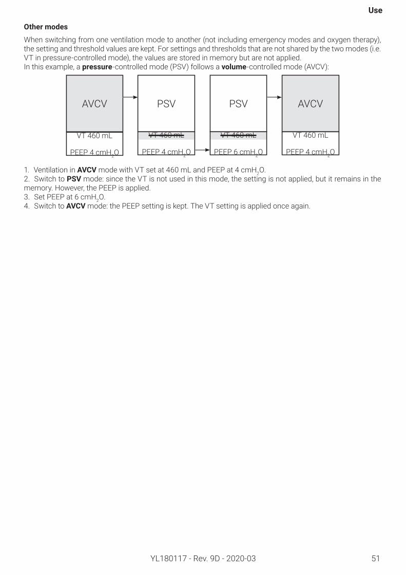
51
Use
YL180117 - Rev. 9D - 2020-03
Othermodes
When switching from one ventilation mode to another (not including emergency modes and oxygen therapy), the setting and threshold values are kept. For settings and thresholds that are not shared by the two modes (i.e. VT in pressure-controlled mode), the values are stored in memory but are not applied.In this example, a pressure-controlled mode (PSV) follows a volume-controlled mode (AVCV):
AVCV PSV PSV AVCV
VT 460 mL
PEEP 4 cmH2O
VT 460 mL
PEEP 4 cmH2O
VT 460 mL
PEEP 6 cmH2O
VT 460 mL
PEEP 4 cmH2O
1. Ventilation in AVCV mode with VT set at 460 mL and PEEP at 4 cmH2O.2. Switch to PSVmode: since the VT is not used in this mode, the setting is not applied, but it remains in the memory. However, the PEEP is applied.3. Set PEEP at 6 cmH2O.4. Switch to AVCV mode: the PEEP setting is kept. The VT setting is applied once again.
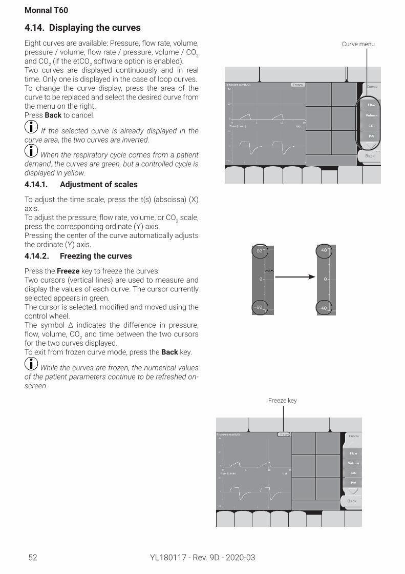
Monnal T60
52 YL180117 - Rev. 9D - 2020-03
4.14. DisplayingthecurvesEightcurvesareavailable:Pressure,flowrate,volume,pressure/volume,flowrate/pressure,volume/CO2 and CO2 (if the etCO2 software option is enabled).Two curves are displayed continuously and in real time. Only one is displayed in the case of loop curves.To change the curve display, press the area of the curve to be replaced and select the desired curve from the menu on the right.Press Back to cancel.
If the selected curve is already displayed in the curve area, the two curves are inverted.
When the respiratory cycle comes from a patient demand, the curves are green, but a controlled cycle is displayed in yellow. 4.14.1. Adjustmentofscales
To adjust the time scale, press the t(s) (abscissa) (X) axis.Toadjustthepressure,flowrate,volume,orCO2 scale, press the corresponding ordinate (Y) axis.Pressing the center of the curve automatically adjusts the ordinate (Y) axis.4.14.2. Freezingthecurves
Press the Freeze key to freeze the curves.Two cursors (vertical lines) are used to measure and display the values of each curve. The cursor currently selected appears in green.Thecursorisselected,modifiedandmovedusingthecontrol wheel. The symbol Δ indicates the difference in pressure,flow,volume,CO2 and time between the two cursors for the two curves displayed.To exit from frozen curve mode, press the Back key.
While the curves are frozen, the numerical values of the patient parameters continue to be refreshed on-screen.
Freeze key
Curve menu
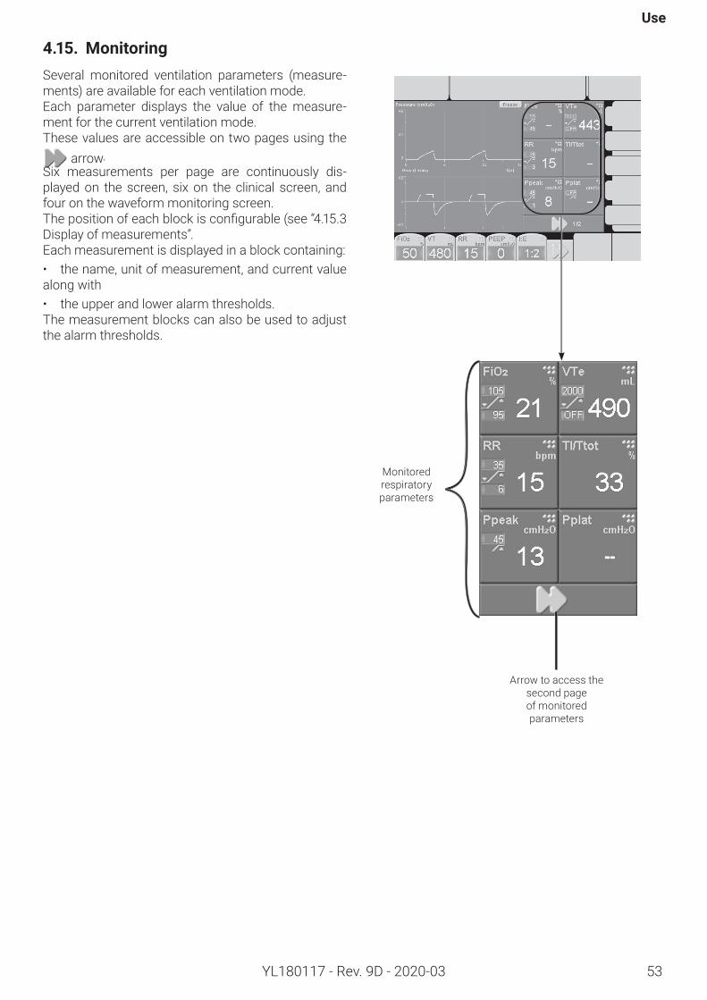
Use
53YL180117 - Rev. 9D - 2020-03
4.15. MonitoringSeveral monitored ventilation parameters (measure-ments) are available for each ventilation mode.Each parameter displays the value of the measure-ment for the current ventilation mode.These values are accessible on two pages using the
arrow.Six measurements per page are continuously dis-played on the screen, six on the clinical screen, and four on the waveform monitoring screen.Thepositionofeachblockisconfigurable(see“4.15.3 Display of measurements”.Each measurement is displayed in a block containing:• the name, unit of measurement, and current value along with• the upper and lower alarm thresholds.The measurement blocks can also be used to adjust the alarm thresholds.
Monitored respiratory parameters
Arrow to access the second page of monitored parameters
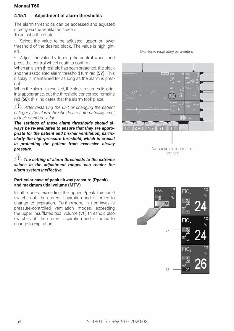
Monnal T60
54 YL180117 - Rev. 9D - 2020-03
4.15.1. Adjustmentofalarmthresholds
The alarm thresholds can be accessed and adjusted directly via the ventilation screen.To adjust a threshold:• Select the value to be adjusted, upper or lower threshold of the desired block. The value is highlight-ed.• Adjust the value by turning the control wheel, and pressthecontrolwheelagaintoconfirm.When an alarm threshold has been breached, the block and the associated alarm threshold turn red(57). This display is maintained for as long as the alarm is pres-ent.When the alarm is resolved, the block resumes its orig-inal appearance, but the threshold concerned remains red (58): this indicates that the alarm took place.
After restarting the unit or changing the patient category, the alarm thresholds are automatically reset to their standard value. The settings of these alarm thresholds should al-ways be re-evaluated to ensure that they are appro-priate for the patient and his/her ventilation, partic-ularly the high-pressure threshold, which is crucial in protecting the patient from excessive airway pressure.
The setting of alarm thresholds to the extreme values in the adjustment ranges can render the alarm system ineffective.
Particularcaseofpeakairwaypressure(Ppeak)andmaximumtidalvolume(MTV)
In all modes, exceeding the upper Ppeak threshold switches off the current inspiration and is forced to change to expiration. Furthermore, in non-invasive pressure-controlled ventilation modes, exceeding theupperinsufflatedtidalvolume(Vti)thresholdalsoswitches off the current inspiration and is forced to change to expiration.
57
58
Monitored respiratory parameters
Access to alarm threshold settings
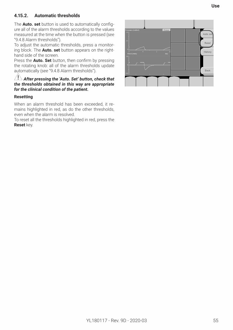
Use
55YL180117 - Rev. 9D - 2020-03
4.15.2. Automaticthresholds
The Auto. setbuttonisusedtoautomaticallyconfig-ure all of the alarm thresholds according to the values measured at the time when the button is pressed (see “9.4.8 Alarm thresholds”).To adjust the automatic thresholds, press a monitor-ing block. The Auto. set button appears on the right-hand side of the screen.Press the Auto. Setbutton,thenconfirmbypressingthe rotating knob: all of the alarm thresholds update automatically (see “9.4.8 Alarm thresholds”).
After pressing the ‘Auto. Set’ button, check that the thresholds obtained in this way are appropriate for the clinical condition of the patient.
Resetting
When an alarm threshold has been exceeded, it re-mains highlighted in red, as do the other thresholds, even when the alarm is resolved.To reset all the thresholds highlighted in red, press the Reset key.
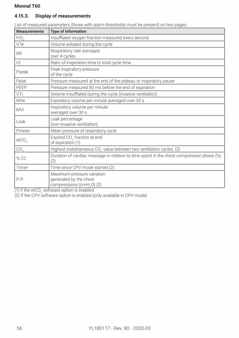
Monnal T60
56 YL180117 - Rev. 9D - 2020-03
4.15.3. Displayofmeasurements
List of measured parameters (those with alarm thresholds must be present) on two pages:Measurements TypeofinformationFiO2 InsufflatedoxygenfractionmeasuredeverysecondVTe Volume exhaled during the cycle
RR Respiratory rate averaged over 4 cycles
I:E Ratio of inspiration time to total cycle time
Ppeak Peak inspiratory pressure of the cycle
Pplat Pressure measured at the end of the plateau or inspiratory pausePEEP Pressure measured 80 ms before the end of expiration VTi Volumeinsufflatedduringthecycle(invasiveventilation)MVe Expiratory volume per minute averaged over 30 s
MVi Inspiratory volume per minute averaged over 30 s.
Leak Leak percentage (non-invasive ventilation)
Pmean Mean pressure of respiratory cycle
etCO2Expired CO2 fraction at end of expiration (1)
CO2 Highest instantaneous CO2 value between two ventilation cycles. (2)
% CC Duration of cardiac massage in relation to time spent in the chest compression phase (%) (2)
Timer Time since CPV mode started (2).
P-PMaximum pressure variation generated by the chest compressions (cmH2O) (2)
(1) if the etCO2 software option is enabled(2) If the CPV software option is enabled (only available in CPV mode)
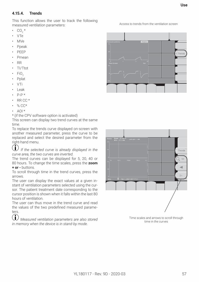
Use
57YL180117 - Rev. 9D - 2020-03
4.15.4. Trends
This function allows the user to track the following measured ventilation parameters:• CO2 *• VTe • MVe • Ppeak• PEEP• Pmean• RR• TI/Ttot• FiO2
• Pplat• VTi• Leak• P-P *• RR CC *• % CC*• AOI ** (if the CPV software option is activated)This screen can display two trend curves at the same time.To replace the trends curve displayed on-screen with another measured parameter, press the curve to be replaced and select the desired parameter from the right-hand menu.
If the selected curve is already displayed in the curve area, the two curves are inverted.The trend curves can be displayed for 5, 20, 40 or 80 hours.Tochangethetimescales,pressthezoom+or-buttons.To scroll through time in the trend curves, press the arrows.The user can display the exact values at a given in-stant of ventilation parameters selected using the cur-sor. The patient treatment date corresponding to the cursor position is shown when it falls within the last 80 hours of ventilation.The user can thus move in the trend curve and read thevaluesof the twopredefinedmeasuredparame-ters.
Measured ventilation parameters are also stored in memory when the device is in stand-by mode.
Access to trends from the ventilation screen
Time scales and arrows to scroll through time in the curves
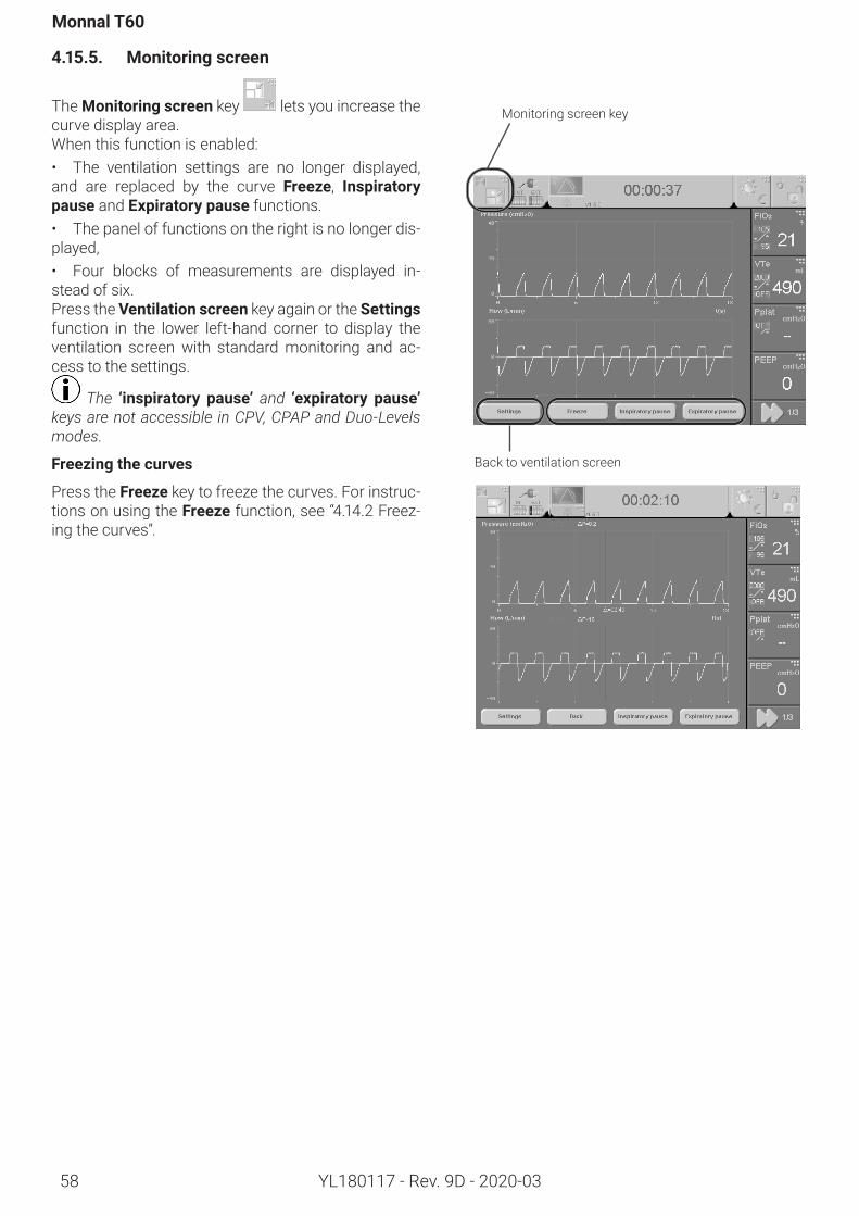
Monnal T60
58 YL180117 - Rev. 9D - 2020-03
4.15.5. Monitoringscreen
TheMonitoringscreen key lets you increase the curve display area.When this function is enabled:• The ventilation settings are no longer displayed, and are replaced by the curve Freeze, Inspiratorypause and Expiratorypause functions.• The panel of functions on the right is no longer dis-played,• Four blocks of measurements are displayed in-stead of six.Press the Ventilationscreen key again or the Settings function in the lower left-hand corner to display the ventilation screen with standard monitoring and ac-cess to the settings.
The ‘inspiratory pause’ and ‘expiratory pause’keys are not accessible in CPV, CPAP and Duo-Levels modes.
Freezingthecurves
Press the Freeze key to freeze the curves. For instruc-tions on using the Freeze function, see “4.14.2 Freez-ing the curves”.
Monitoring screen key
Back to ventilation screen
Use
59YL180117 - Rev. 9D - 2020-03
Inspiratorypause
The Inspiratorypause key is used to perform an in-spiratory pause (limited to 40 seconds). The pause continues for as long as the user holds down the key. When the user stops the hold, the ventilator resumes ventilation with the parameters set previously.
Expiratorypause
The Expiratorypausekey is used to perform an ex-piratory pause (limited to 60 seconds). The pause continues for as long as the user holds down the key. When the user stops the hold, the ventilator resumes ventilation with the parameters set previously.
The inspiratory and expiratory pauses are not available in CPV, CPAP and Duo-Levels.
After the execution of a pause, a curve freeze can be performed in order to measure the plateau pres-sure and the auto PEEP value using cursors.
The plateau pressure value is refreshed:- After an inspiratory pause;- In the event of an inspiratory plateau lasting longer than 0.3 s (in VCV)- When the inspiratory plateau is not activated, the Pplat measurement is displayed as follows: .
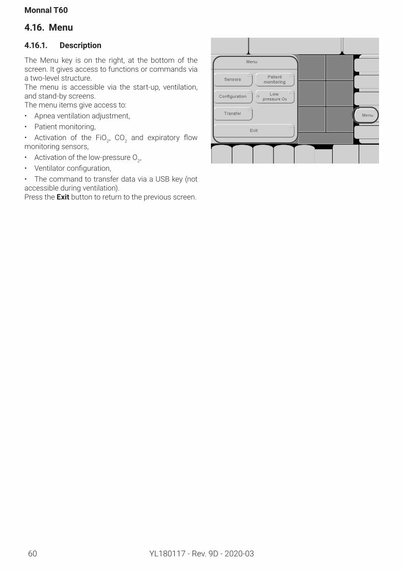
Monnal T60
60 YL180117 - Rev. 9D - 2020-03
4.16. Menu
4.16.1. Description
The Menu key is on the right, at the bottom of the screen. It gives access to functions or commands via a two-level structure. The menu is accessible via the start-up, ventilation, and stand-by screens.The menu items give access to:• Apnea ventilation adjustment,• Patient monitoring,• Activation of the FiO2, CO2 and expiratory flowmonitoring sensors,• Activation of the low-pressure O2,• Ventilatorconfiguration,• The command to transfer data via a USB key (not accessible during ventilation).Press the Exit button to return to the previous screen.
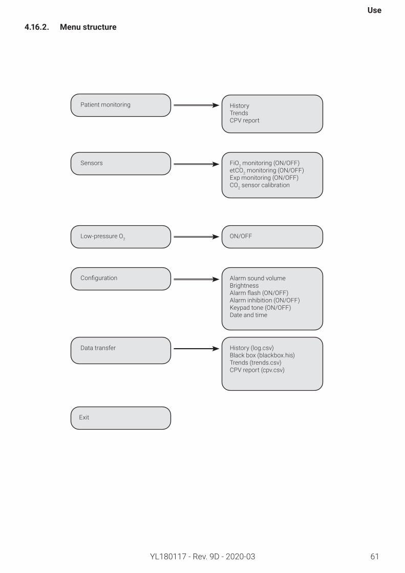
61
Use
YL180117 - Rev. 9D - 2020-03
4.16.2. Menustructure
Data transfer History (log.csv)Black box (blackbox.his)Trends (trends.csv)CPV report (cpv.csv)
Patient monitoring HistoryTrendsCPV report
Sensors FiO2 monitoring (ON/OFF) etCO2 monitoring (ON/OFF)Exp monitoring (ON/OFF)CO2 sensor calibration
Low-pressure O2 ON/OFF
Configuration Alarm sound volumeBrightnessAlarmflash(ON/OFF)Alarm inhibition (ON/OFF)Keypad tone (ON/OFF)Date and time
Exit
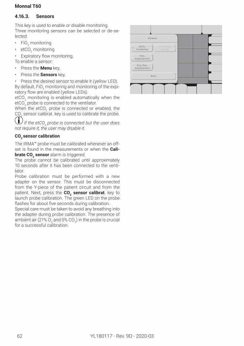
Monnal T60
62 YL180117 - Rev. 9D - 2020-03
4.16.3. Sensors
This key is used to enable or disable monitoring.Three monitoring sensors can be selected or de-se-lected:• FiO2 monitoring • etCO2 monitoring• Expiratoryflowmonitoring.To enable a sensor:• Press the Menu key,• Press the Sensors key,• Press the desired sensor to enable it (yellow LED).By default, FiO2 monitoring and monitoring of the expi-ratoryflowareenabled(yellowLEDs).etCO2 monitoring is enabled automatically when the etCO2 probe is connected to the ventilator. When the etCO2 probe is connected or enabled, the CO2 sensor calibrat. key is used to calibrate the probe.
If the etCO2 probe is connected but the user does not require it, the user may disable it.
CO2 sensorcalibration
The IRMA™ probe must be calibrated whenever an off-set is found in the measurements or when the Cali-brate CO2 sensor alarm is triggered.The probe cannot be calibrated until approximately 10 secondsafter ithasbeenconnectedtotheventi-lator. Probe calibration must be performed with a new adapter on the sensor. This must be disconnected from the Y-piece of the patient circuit and from the patient. Next, press the CO2 sensor calibrat. key to launch probe calibration. The green LED on the probe flashesforaboutfivesecondsduringcalibration.Special care must be taken to avoid any breathing into the adapter during probe calibration. The presence of ambient air (21% O2 and 0% CO2) in the probe is crucial for a successful calibration.
Use
63YL180117 - Rev. 9D - 2020-03
4.16.4. Low-pressureO2
This function allows the machine to enrich the O2 mix-turefroma low-pressuresource, typicallya lowflowmeter on an O2 cylinder or a concentrator. This is different from connecting it to a high-pressure source, as it involves lower quantities (pressure gen-erallybelow1bar,flowlessthan10L/min);Accordingto the nature of the source and the ventilation settings, certain FiO2 values cannot be guaranteed. An align-ment chart is provided for information in Section “9. Technical description”.To enable the low-pressure O2 function, press Menu and then Low-pressureO2. The message ‘Low-pressure O2 enabled’ (informa-tion) then appears in the alarm panel.The gas mixture is O2-enriched and monitored in con-junction with the FiO2 setting parameter, and the ma-chine supplies the desired concentration insofar as possible. If the ventilation and low-pressure source settings are incompatible, the FiO2 will not be reached, and the LowFiO2!!! alarm will be triggered. The user will then be informedthatthesettingsneedtobemodified.
During operation with a high-pressure source, the 100% O2 function can be enabled. This possibility is maintained in low-pressure operation dependent on the O2 supply flow and the patient’s ventilation. The maximum concentration that can be achieved none-theless depends on the source and the ventilation set-tings.
To guarantee satisfactory operation from a low flow O2 supply on a concentrator, the high-pressure O2 hose must be disconnected from the machine.
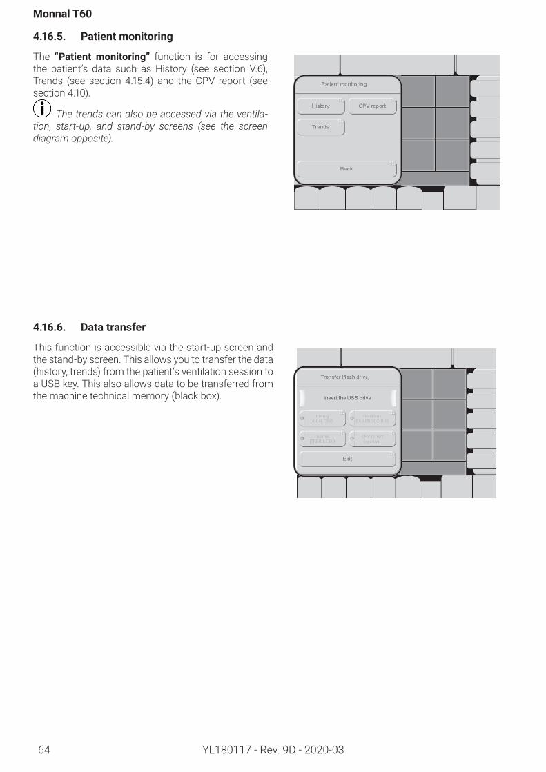
Monnal T60
64 YL180117 - Rev. 9D - 2020-03
4.16.5. Patientmonitoring
The “Patient monitoring” function is for accessing the patient’s data such as History (see section V.6), Trends (see section 4.15.4) and the CPV report (see section 4.10).
The trends can also be accessed via the ventila-tion, start-up, and stand-by screens (see the screen diagram opposite).
4.16.6. Data transfer
This function is accessible via the start-up screen and the stand-by screen. This allows you to transfer the data (history, trends) from the patient’s ventilation session to a USB key. This also allows data to be transferred from the machine technical memory (black box).
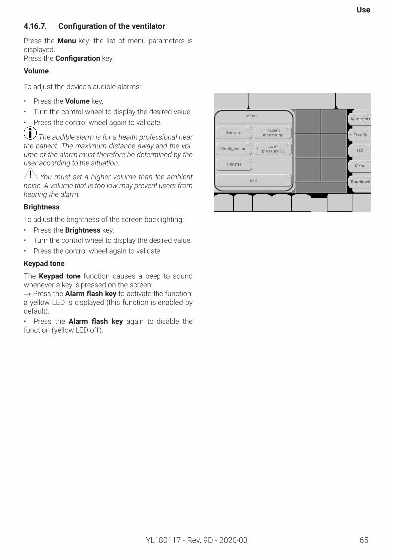
Use
65YL180117 - Rev. 9D - 2020-03
4.16.7. Configurationoftheventilator
Press the Menu key: the list of menu parameters is displayed.Press the Configuration key.
Volume
To adjust the device’s audible alarms:
• Press the Volume key, • Turn the control wheel to display the desired value,• Press the control wheel again to validate.
The audible alarm is for a health professional near the patient. The maximum distance away and the vol-ume of the alarm must therefore be determined by the user according to the situation.
You must set a higher volume than the ambient noise. A volume that is too low may prevent users from hearing the alarm.
Brightness
To adjust the brightness of the screen backlighting: • Press the Brightness key, • Turn the control wheel to display the desired value,• Press the control wheel again to validate.
Keypadtone
The Keypad tone function causes a beep to sound whenever a key is pressed on the screen:→ Press the Alarmflashkey to activate the function: a yellow LED is displayed (this function is enabled by default).• Press the Alarm flash key again to disable the function (yellow LED off).
Monnal T60
66 YL180117 - Rev. 9D - 2020-03
Alarmflash
The Alarm flash function allows you to enable the presence of the casing indicator light on the front pan-el of the machine.→ Press the Alarmflash key to activate the function: a yellow LED is displayed (this function is enabled by default).• Press the Alarm flash key again to disable the function (yellow LED off).
Alarminhibition
The “PreventiveAlarm Inhibition” function silences the audible alarms on the Monnal T60 for 2 minutes.→ Press the “Alarm Inhibition” key to enable the function: a yellow LED is displayed (this function is disabled by default).
Date/Time(Instand-byonly)
To set the date and time on the machine, press the Date/Time key.To adjust each parameter (day / month / year / hour / minute):• Turn the control wheel to display the desired value,• Pressthecontrolwheeltoconfirmandproceedtothe next value.
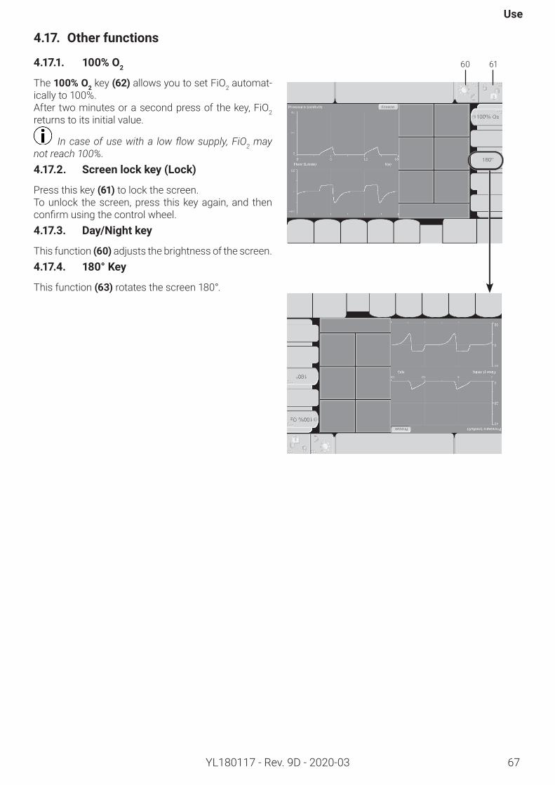
Use
67YL180117 - Rev. 9D - 2020-03
4.17. Otherfunctions
4.17.1. 100% O2
The 100% O2 key (62) allows you to set FiO2 automat-ically to 100%. After two minutes or a second press of the key, FiO2 returns to its initial value.
In case of use with a low flow supply, FiO2 may not reach 100%.4.17.2. Screenlockkey(Lock)
Press this key(61) to lock the screen. To unlock the screen, press this key again, and then confirmusingthecontrolwheel.4.17.3. Day/Nightkey
This function(60) adjusts the brightness of the screen. 4.17.4. 180° Key
This function (63)rotates the screen 180°.
60 61
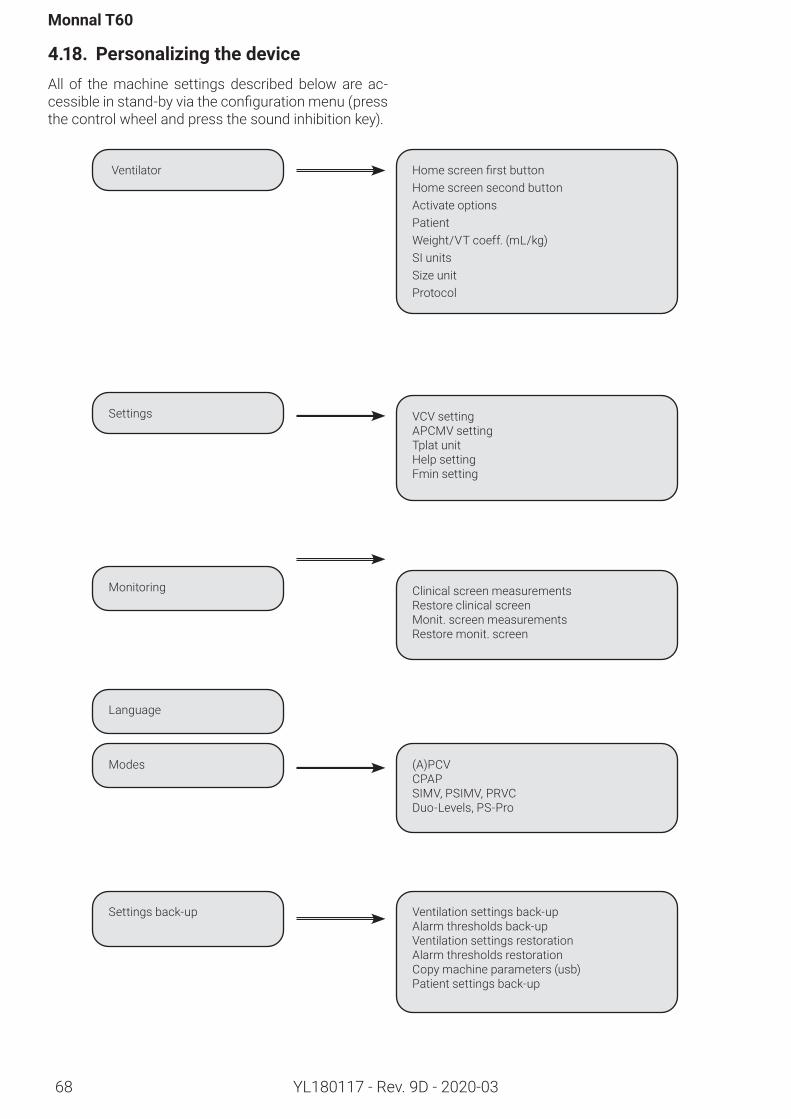
Monnal T60
68 YL180117 - Rev. 9D - 2020-03
4.18. PersonalizingthedeviceAll of the machine settings described below are ac-cessibleinstand-byviatheconfigurationmenu(pressthe control wheel and press the sound inhibition key).
Ventilator HomescreenfirstbuttonHome screen second buttonActivate optionsPatientWeight/VT coeff. (mL/kg) SI unitsSize unitProtocol
VCV settingAPCMV settingTplat unitHelp settingFmin setting
Settings
(A)PCVCPAPSIMV, PSIMV, PRVCDuo-Levels, PS-Pro
Modes
Language
Clinical screen measurementsRestore clinical screenMonit. screen measurementsRestore monit. screen
Monitoring
Ventilation settings back-upAlarm thresholds back-upVentilation settings restorationAlarm thresholds restorationCopy machine parameters (usb)Patient settings back-up
Settings back-up
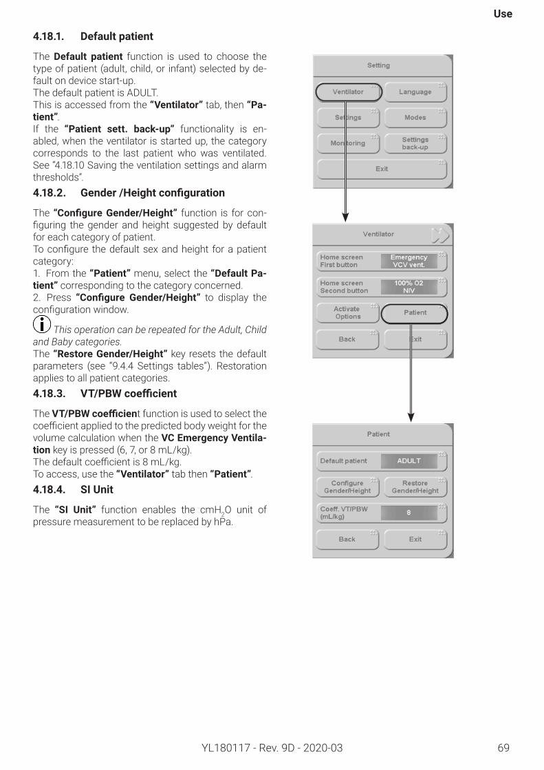
Use
69YL180117 - Rev. 9D - 2020-03
4.18.1. Defaultpatient
The Default patient function is used to choose the type of patient (adult, child, or infant) selected by de-fault on device start-up.The default patient is ADULT.This is accessed from the “Ventilator” tab, then “Pa-tient”.If the “Patient sett. back-up” functionality is en-abled, when the ventilator is started up, the category corresponds to the last patient who was ventilated. See “4.18.10 Saving the ventilation settings and alarm thresholds”.4.18.2. Gender/Heightconfiguration
The “ConfigureGender/Height” function is for con-figuring thegender andheight suggestedby defaultfor each category of patient. Toconfigure thedefaultsexandheight forapatientcategory:1. From the “Patient” menu, select the “DefaultPa-tient” corresponding to the category concerned.2. Press “Configure Gender/Height” to display the configurationwindow.
This operation can be repeated for the Adult, Child and Baby categories.The “RestoreGender/Height” key resets the default parameters (see “9.4.4 Settings tables”). Restoration applies to all patient categories.4.18.3. VT/PBWcoefficient
The VT/PBWcoefficient function is used to select the coefficientappliedtothepredictedbodyweightforthevolume calculation when the VCEmergencyVentila-tion key is pressed (6, 7, or 8 mL/kg).Thedefaultcoefficientis8mL/kg.To access, use the “Ventilator”tab then “Patient”.4.18.4. SIUnit
The “SI Unit” function enables the cmH2O unit of pressure measurement to be replaced by hPa.
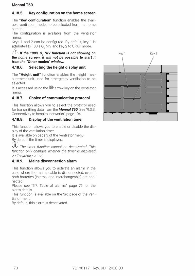
Monnal T60
70 YL180117 - Rev. 9D - 2020-03
4.18.5. Keyconfigurationonthehomescreen
The “Key configuration” function enables the avail-able ventilation modes to be selected from the home screen.The configuration is available from the Ventilatormenu.Keys1and2canbeconfigured.Bydefault,key1 isattributed to 100% O2 NIV and key 2 to CPAP mode.
If the 100% O2 NIV function is not showing on the home screen, it will not be possible to start it from the “Othermodes” window.4.18.6. Selectingtheheightdisplayunit
The “Height unit” function enables the height mea-surement unit used for emergency ventilation to be selected. It is accessed using the arrow key on the Ventilator menu.4.18.7. Choiceofcommunicationprotocol
This function allows you to select the protocol used for transmitting data from the Monnal T60. See “9.3.3. Connectivity to hospital networks”, page 104.4.18.8. Displayoftheventilationtimer
This function allows you to enable or disable the dis-play of the ventilation timer.It is available on page 3 of the Ventilator menu.By default, the timer is displayed.
The timer function cannot be deactivated. This function only changes whether the timer is displayed on the screen or not.4.18.9. Mainsdisconnectionalarm
This function allows you to activate an alarm in the case where the mains cable is disconnected, even if both batteries (internal and interchangeable) are con-nected.Please see “5.7. Table of alarms”, page 76 for the alarm details.This function is available on the 3rd page of the Ven-tilator menu.By default, this alarm is deactivated.
Key 1 Key 2
Use
YL180117 - Rev. 9D - 2020-03 71
4.18.10. Savingtheventilationsettingsandalarmthresholds
Settings can be saved for each category and each type of ventilation:• Invasive ventilation• Non-invasive ventilation• Emergency ventilation VCV• 100% O2 NIV• CPV (if enabled)Likewise, the alarm threshold settings for each cate-gory and for the following two types of ventilation can be saved:• Invasive ventilation• Non-invasive ventilationTheseareaccesseddirectlyvia thefirstpageof theconfigurationmenu.The Restore keys are used to reset the set-points and/or thresholds to the default values. Restoration applies toallconfigurationsandallpatientcategories.
Confusion may arise if different alarm settings are used on different devices within the same zone, for example an intensive care unit or a heart surgery room.If the device is shut down, the “Savepatientsettings” key allows the device to be restarted using the set-tings of the last ventilation
If it is started up without a patient category selec-tion, the following settings are retained:• Patient type (category, height and gender)• Ventilation mode (set-points, alarm thresholds)4.18.11. Set-pointselection
The Set-points function is used to select the set-points to be used according to application:• I:E, Ti/Ttot, Ti or Flow rate in VCV• I:E, Ti/Ttot or Ti in PCV• Tplat in % or seconds in VCV and SIMV• PS or PI in PSV and SIMV• RR min enabled or disabled in PSV
4.18.12. Displayofthemonitoringblocks
The Monitoring function allows the user to change the display order of the monitoring blocks in the clini-cal display(measuresclinicscreen)and in the mon-itoring display(measureswidescreen).Theconfigu-rations are independent between the screens.The [Restoration] keys allow you to reset the order of the monitoring blocks on each screen.These functions are available from the [Ventilator]menu.
In clinical mode, the display of the Pplat and Leak monitoring blocks on the first page change according to the ventilation type. In invasive ventilation, Leak is replaced by Pplat, and vice versa in non-invasive ven-tilation.4.18.13. Displaymodesinthe‘othermodes’window
The Ventilationmodes function is used to choose the modes that will appear in the Othermodes window, and therefore to remove unused modes if necessary.
VCV and PSV modes cannot be disabled.
To transfer all of the configurations from one ma-chine to another, use a USB key and go into the Savesettings tab, and then Copy machine parameters(USB).The ‘Monnal=>USBKey’ key is used to save all the settings on a machine to the USB key.The ‘USBkey=>Monnal’key is used to load onto the machine all the settings entered into another machine and then stored on the USB key.
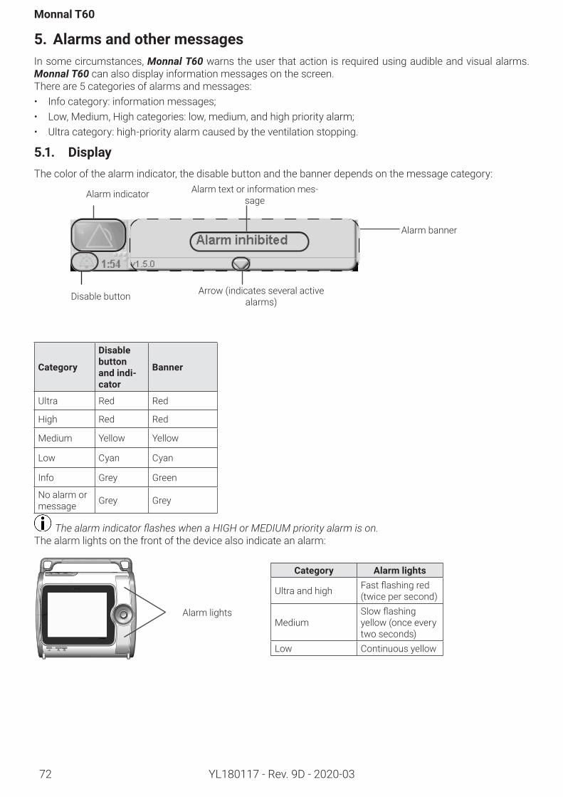
72
Monnal T60
YL180117 - Rev. 9D - 2020-03
5. AlarmsandothermessagesIn some circumstances, Monnal T60 warns the user that action is required using audible and visual alarms. Monnal T60 can also display information messages on the screen.There are 5 categories of alarms and messages: • Info category: information messages;• Low, Medium, High categories: low, medium, and high priority alarm;• Ultra category: high-priority alarm caused by the ventilation stopping.
5.1. DisplayThe color of the alarm indicator, the disable button and the banner depends on the message category:
Category
Disablebutton andindi-cator
Banner
Ultra Red Red
High Red Red
Medium Yellow Yellow
Low Cyan Cyan
Info Grey Green
No alarm or message Grey Grey
The alarm indicator flashes when a HIGH or MEDIUM priority alarm is on.The alarm lights on the front of the device also indicate an alarm:
Disable button Arrow (indicates several active alarms)
Alarm banner
Alarm indicator Alarm text or information mes-sage
Alarm lights
Category Alarmlights
Ultra and high Fastflashingred(twice per second)
MediumSlowflashingyellow (once every two seconds)
Low Continuous yellow
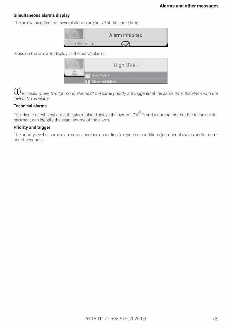
73
Alarmsandothermessages
YL180117 - Rev. 9D - 2020-03
Simultaneousalarmsdisplay
The arrow indicates that several alarms are active at the same time:
Press on the arrow to display all the active alarms:
In cases where two (or more) alarms of the same priority are triggered at the same time, the alarm with the lowest No. is visible.
Technicalalarms
To indicate a technical error, the alarm also displays the symbol (“ ”) and a number so that the technical de-partment can identify the exact source of the alarm.
Priorityandtrigger
The priority level of some alarms can increase according to repeated conditions (number of cycles and/or num-ber of seconds).
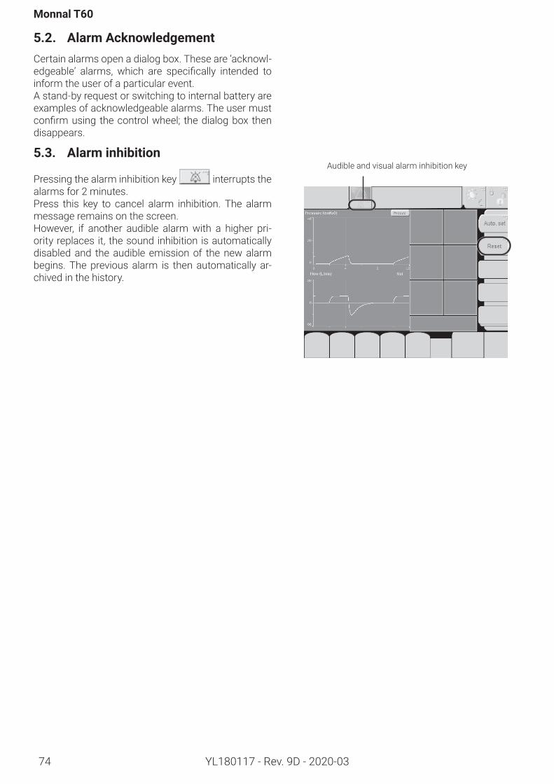
Monnal T60
74 YL180117 - Rev. 9D - 2020-03
5.2. AlarmAcknowledgementCertain alarms open a dialog box. These are ‘acknowl-edgeable’ alarms, which are specifically intended toinform the user of a particular event. A stand-by request or switching to internal battery are examples of acknowledgeable alarms. The user must confirmusing thecontrolwheel; thedialogbox thendisappears.
5.3. Alarminhibition
Pressing the alarm inhibition key interrupts the alarms for 2 minutes.Press this key to cancel alarm inhibition. The alarm message remains on the screen. However, if another audible alarm with a higher pri-ority replaces it, the sound inhibition is automatically disabled and the audible emission of the new alarm begins. The previous alarm is then automatically ar-chived in the history.
Audible and visual alarm inhibition key
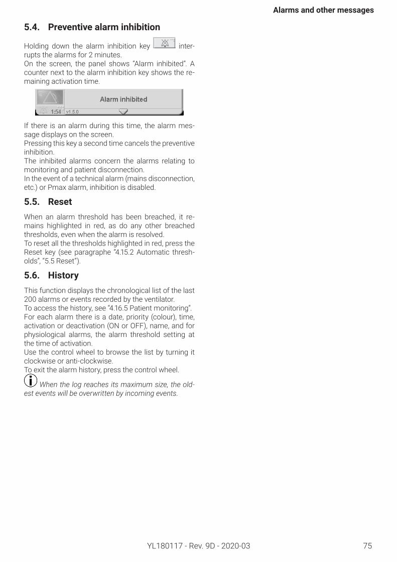
Alarmsandothermessages
75YL180117 - Rev. 9D - 2020-03
5.4. Preventivealarminhibition
Holding down the alarm inhibition key inter-rupts the alarms for 2 minutes.On the screen, the panel shows “Alarm inhibited”. A counter next to the alarm inhibition key shows the re-maining activation time.
If there is an alarm during this time, the alarm mes-sage displays on the screen.Pressing this key a second time cancels the preventive inhibition. The inhibited alarms concern the alarms relating to monitoring and patient disconnection.In the event of a technical alarm (mains disconnection, etc.) or Pmax alarm, inhibition is disabled.
5.5. ResetWhen an alarm threshold has been breached, it re-mains highlighted in red, as do any other breached thresholds, even when the alarm is resolved.To reset all the thresholds highlighted in red, press the Reset key (see paragraphe “4.15.2 Automatic thresh-olds”, “5.5 Reset”).
5.6. HistoryThis function displays the chronological list of the last 200 alarms or events recorded by the ventilator. To access the history, see “4.16.5 Patient monitoring”.For each alarm there is a date, priority (colour), time, activation or deactivation (ON or OFF), name, and for physiological alarms, the alarm threshold setting at the time of activation. Use the control wheel to browse the list by turning it clockwise or anti-clockwise.To exit the alarm history, press the control wheel.
When the log reaches its maximum size, the old-est events will be overwritten by incoming events.
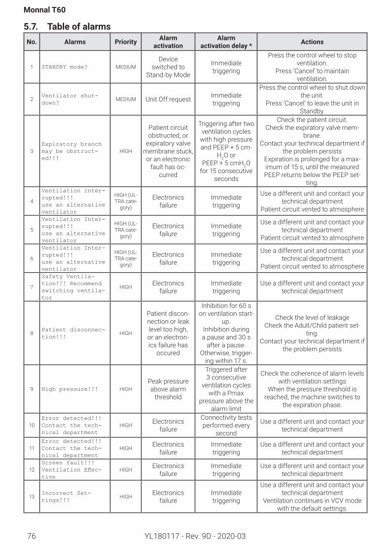
76
Monnal T60
YL180117 - Rev. 9D - 2020-03
5.7. Table of alarmsNo. Alarms Priority Alarm
activationAlarm
activationdelay* Actions
1 STANDBY mode? MEDIUMDevice
switched to Stand-by Mode
Immediate triggering
Press the control wheel to stop ventilation.
Press ‘Cancel’ to maintain ventilation.
2Ventilator shut-down?
MEDIUM Unit Off request Immediate triggering
Press the control wheel to shut down the unit.
Press ‘Cancel’ to leave the unit in Standby.
3Expiratory branch may be obstruct-ed!!!
HIGH
Patient circuit obstructed, or
expiratory valve membrane stuck, or an electronic
fault has oc-curred
Triggering after two ventilation cycles
with high pressure and PEEP + 5 cm-
H2O or PEEP + 5 cmH2O
for 15 consecutive seconds
Check the patient circuit.Check the expiratory valve mem-
brane.Contact your technical department if
the problem persistsExpiration is prolonged for a max-imum of 15 s, until the measured PEEP returns below the PEEP set-
ting.
4
Ventilation Inter-rupted!!! use an alternative ventilator
HIGH (UL-TRA cate-
gory)
Electronics failure
Immediate triggering
Use a different unit and contact your technical department
Patient circuit vented to atmosphere
5
Ventilation Inter-rupted!!! use an alternative ventilator
HIGH (UL-TRA cate-
gory)
Electronics failure
Immediate triggering
Use a different unit and contact your technical department
Patient circuit vented to atmosphere
6
Ventilation Inter-rupted!!! use an alternative ventilator
HIGH (UL-TRA cate-
gory)
Electronics failure
Immediate triggering
Use a different unit and contact your technical department
Patient circuit vented to atmosphere
7
Safety Ventila-tion!!! Recommend switching ventila-tor
HIGH Electronics failure
Immediate triggering
Use a different unit and contact your technical department
8Patient disconnec-tion!!!
HIGH
Patient discon-nection or leak level too high, or an electron-ics failure has
occured
Inhibitionfor60 son ventilation start-
up. Inhibition during a pause and 30 s
after a pause.Otherwise, trigger-
ing within 17 s.
Check the level of leakageCheck the Adult/Child patient set-
ting.Contact your technical department if
the problem persists
9 High pressure!!! HIGHPeak pressure above alarm
threshold
Triggered after 3 consecutive
ventilation cycles with a Pmax
pressure above the alarm limit
Check the coherence of alarm levels with ventilation settings
When the pressure threshold is reached, the machine switches to
the expiration phase.
10Error detected!!! Contact the tech-nical department
HIGH Electronics failure
Connectivity tests performed every
second
Use a different unit and contact your technical department
11Error detected!!! Contact the tech-nical department
HIGH Electronics failure
Immediate triggering
Use a different unit and contact your technical department
12Screen fault!!! Ventilation Effec-tive
HIGH Electronics failure
Immediate triggering
Use a different unit and contact your technical department
13Incorrect Set-tings!!!
HIGH Electronics failure
Immediate triggering
Use a different unit and contact your technical department
Ventilation continues in VCV mode with the default settings.
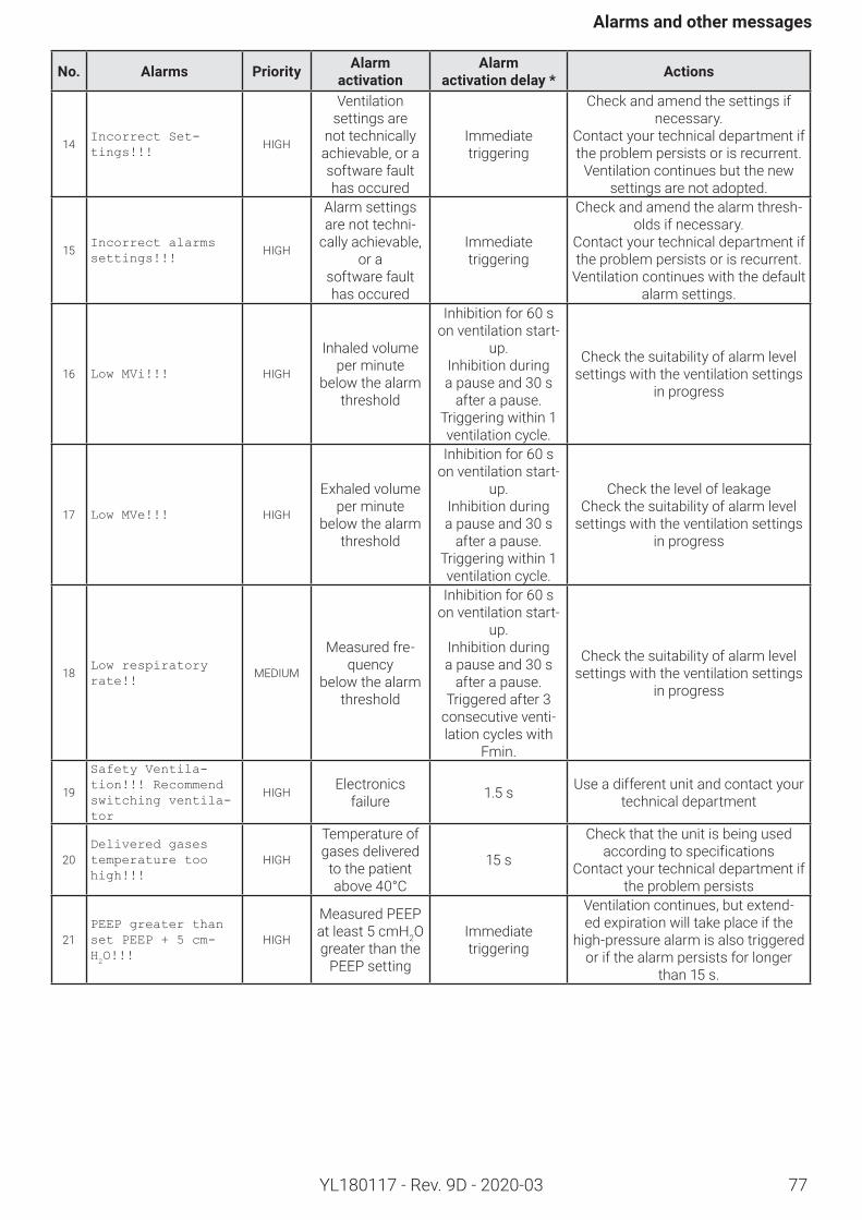
77
Alarmsandothermessages
YL180117 - Rev. 9D - 2020-03
No. Alarms Priority Alarm activation
Alarm activationdelay* Actions
14Incorrect Set-tings!!!
HIGH
Ventilation settings are
not technically achievable, or a software fault has occured
Immediate triggering
Check and amend the settings if necessary.
Contact your technical department if the problem persists or is recurrent.
Ventilation continues but the new settings are not adopted.
15Incorrect alarms settings!!!
HIGH
Alarm settings are not techni-
cally achievable, or a
software fault has occured
Immediate triggering
Check and amend the alarm thresh-olds if necessary.
Contact your technical department if the problem persists or is recurrent.
Ventilation continues with the default alarm settings.
16 Low MVi!!! HIGH
Inhaled volume per minute
below the alarm threshold
Inhibitionfor60 son ventilation start-
up.Inhibition during a pause and 30 s
after a pause.Triggering within 1 ventilation cycle.
Check the suitability of alarm level settings with the ventilation settings
in progress
17 Low MVe!!! HIGH
Exhaled volume per minute
below the alarm threshold
Inhibitionfor60 son ventilation start-
up.Inhibition during apauseand30 s
after a pause.Triggering within 1 ventilation cycle.
Check the level of leakageCheck the suitability of alarm level
settings with the ventilation settings in progress
18Low respiratory rate!!
MEDIUM
Measured fre-quency
below the alarm threshold
Inhibitionfor60 son ventilation start-
up.Inhibition during apauseand30 s
after a pause.Triggered after 3
consecutive venti-lation cycles with
Fmin.
Check the suitability of alarm level settings with the ventilation settings
in progress
19
Safety Ventila-tion!!! Recommend switching ventila-tor
HIGH Electronics failure 1.5 s Use a different unit and contact your
technical department
20Delivered gases temperature too high!!!
HIGH
Temperature of gases delivered
to the patient above 40°C
15 s
Check that the unit is being used according to specifications
Contact your technical department if the problem persists
21PEEP greater than set PEEP + 5 cm-H2O!!!
HIGH
Measured PEEP atleast5 cmH2O greater than the
PEEP setting
Immediate triggering
Ventilation continues, but extend-ed expiration will take place if the
high-pressure alarm is also triggered or if the alarm persists for longer
than 15 s.
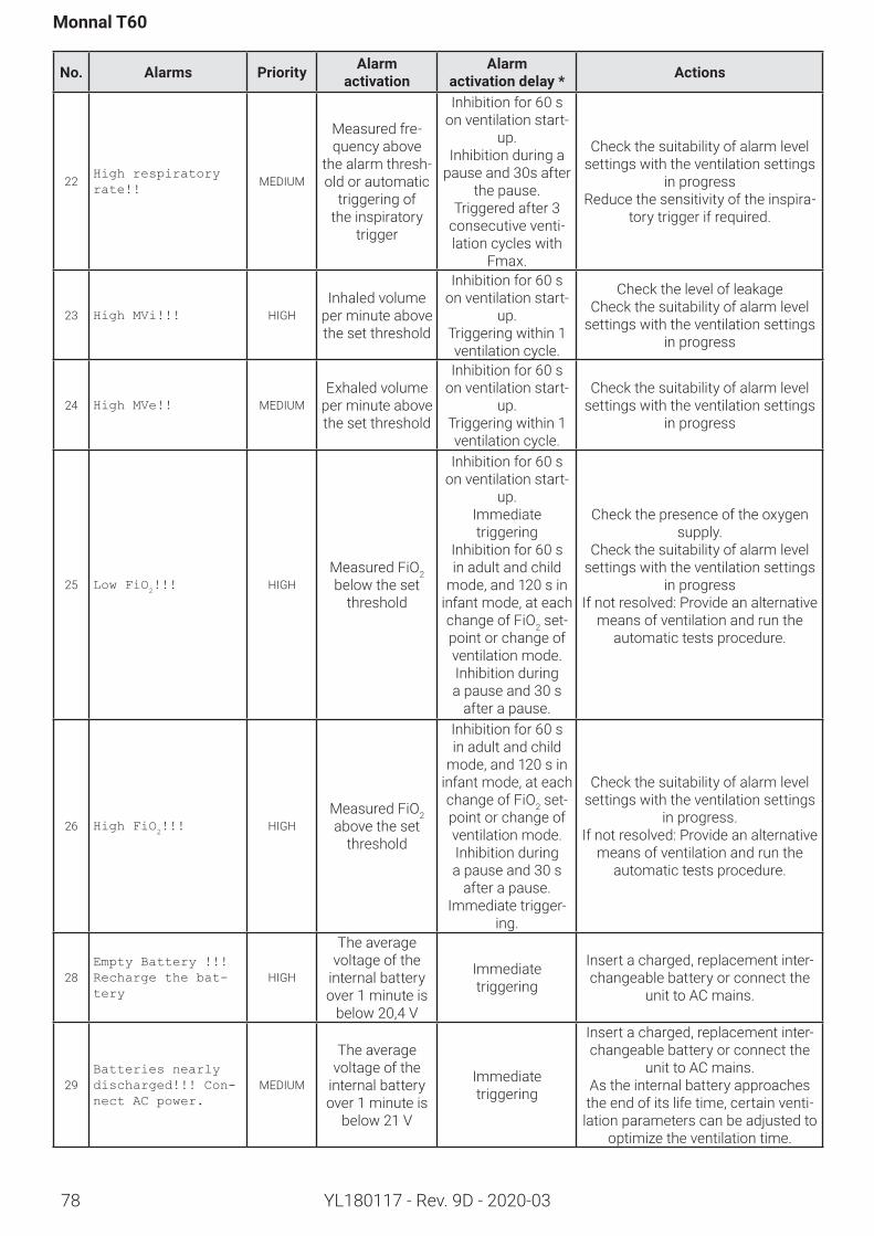
78
Monnal T60
YL180117 - Rev. 9D - 2020-03
No. Alarms Priority Alarm activation
Alarm activationdelay* Actions
22High respiratory rate!!
MEDIUM
Measured fre-quency above
the alarm thresh-old or automatic
triggering of the inspiratory
trigger
Inhibitionfor60 son ventilation start-
up.Inhibition during a
pause and 30s after the pause.
Triggered after 3 consecutive venti-lation cycles with
Fmax.
Check the suitability of alarm level settings with the ventilation settings
in progressReduce the sensitivity of the inspira-
tory trigger if required.
23 High MVi!!! HIGHInhaled volume
per minute above the set threshold
Inhibitionfor60 son ventilation start-
up.Triggering within 1 ventilation cycle.
Check the level of leakageCheck the suitability of alarm level
settings with the ventilation settings in progress
24 High MVe!! MEDIUMExhaled volume
per minute above the set threshold
Inhibitionfor60 son ventilation start-
up.Triggering within 1 ventilation cycle.
Check the suitability of alarm level settings with the ventilation settings
in progress
25 Low FiO2!!! HIGH
Measured FiO2 below the set
threshold
Inhibitionfor60 son ventilation start-
up.Immediate triggering
Inhibition for 60 s in adult and child
mode, and 120 s in infant mode, at each change of FiO2 set-point or change of ventilation mode.Inhibition during a pause and 30 s
after a pause.
Check the presence of the oxygen supply.
Check the suitability of alarm level settings with the ventilation settings
in progressIf not resolved: Provide an alternative
means of ventilation and run the automatic tests procedure.
26 High FiO2!!! HIGH
Measured FiO2 above the set
threshold
Inhibition for 60 s in adult and child
mode, and 120 s in infant mode, at each change of FiO2 set-point or change of ventilation mode. Inhibition during a pause and 30 s
after a pause.Immediate trigger-
ing.
Check the suitability of alarm level settings with the ventilation settings
in progress.If not resolved: Provide an alternative
means of ventilation and run the automatic tests procedure.
28Empty Battery !!! Recharge the bat-tery
HIGH
The average voltage of the
internal battery over 1 minute is
below 20,4 V
Immediate triggering
Insert a charged, replacement inter-changeable battery or connect the
unit to AC mains.
29Batteries nearly discharged!!! Con-nect AC power.
MEDIUM
The average voltage of the
internal battery over 1 minute is
below 21 V
Immediate triggering
Insert a charged, replacement inter-changeable battery or connect the
unit to AC mains.As the internal battery approaches the end of its life time, certain venti-lation parameters can be adjusted to
optimize the ventilation time.
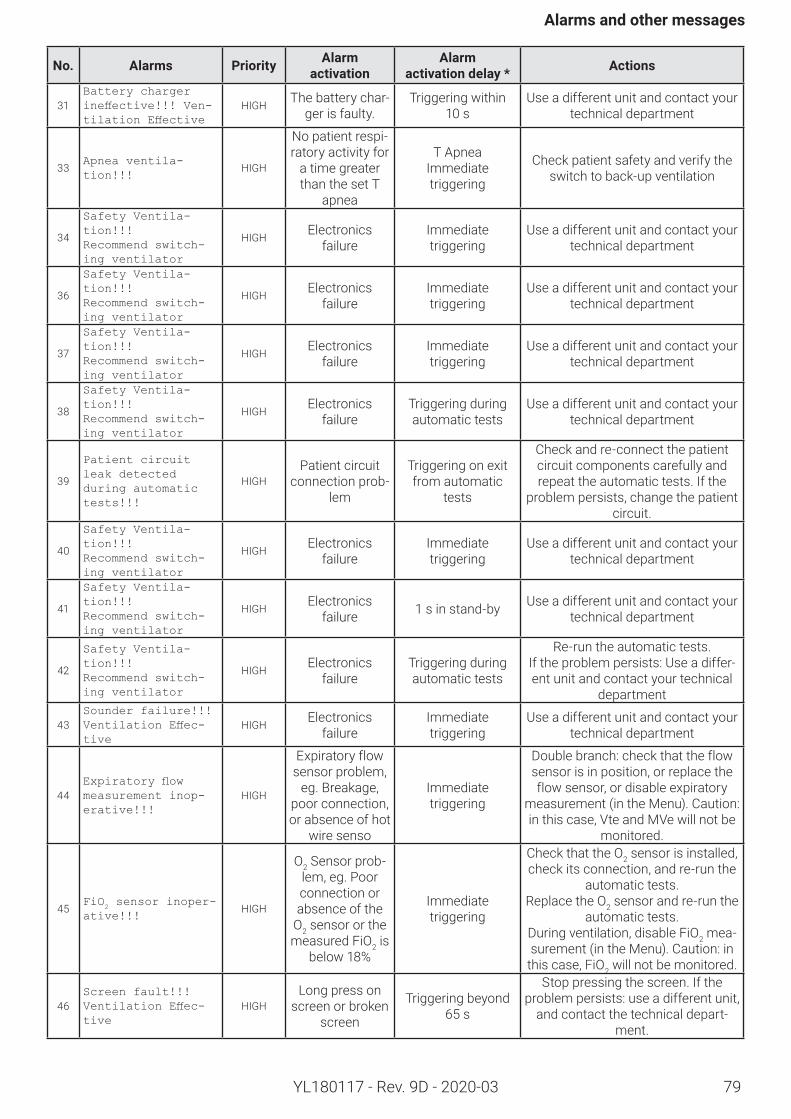
79
Alarmsandothermessages
YL180117 - Rev. 9D - 2020-03
No. Alarms Priority Alarm activation
Alarm activationdelay* Actions
31Battery charger ineffective!!! Ven-tilation Effective
HIGH The battery char-ger is faulty.
Triggering within 10 s
Use a different unit and contact your technical department
33Apnea ventila-tion!!!
HIGH
No patient respi-ratory activity for
a time greater than the set T
apnea
T ApneaImmediate triggering
Check patient safety and verify the switch to back-up ventilation
34
Safety Ventila-tion!!!Recommend switch-ing ventilator
HIGH Electronics failure
Immediate triggering
Use a different unit and contact your technical department
36
Safety Ventila-tion!!!Recommend switch-ing ventilator
HIGH Electronics failure
Immediate triggering
Use a different unit and contact your technical department
37
Safety Ventila-tion!!!Recommend switch-ing ventilator
HIGH Electronics failure
Immediate triggering
Use a different unit and contact your technical department
38
Safety Ventila-tion!!!Recommend switch-ing ventilator
HIGH Electronics failure
Triggering during automatic tests
Use a different unit and contact your technical department
39
Patient circuit leak detected during automatic tests!!!
HIGHPatient circuit
connection prob-lem
Triggering on exit from automatic
tests
Check and re-connect the patient circuit components carefully and repeat the automatic tests. If the
problem persists, change the patient circuit.
40
Safety Ventila-tion!!!Recommend switch-ing ventilator
HIGH Electronics failure
Immediate triggering
Use a different unit and contact your technical department
41
Safety Ventila-tion!!!Recommend switch-ing ventilator
HIGH Electronics failure 1 s in stand-by Use a different unit and contact your
technical department
42
Safety Ventila-tion!!!Recommend switch-ing ventilator
HIGH Electronics failure
Triggering during automatic tests
Re-run the automatic tests.If the problem persists: Use a differ-ent unit and contact your technical
department
43Sounder failure!!! Ventilation Effec-tive
HIGH Electronics failure
Immediate triggering
Use a different unit and contact your technical department
44Expiratory flow measurement inop-erative!!!
HIGH
Expiratory flow sensor problem,
eg. Breakage, poor connection, or absence of hot
wire senso
Immediate triggering
Double branch: check that the flow sensor is in position, or replace the flow sensor, or disable expiratory
measurement (in the Menu). Caution: in this case, Vte and MVe will not be
monitored.
45FiO
2 sensor inoper-
ative!!!HIGH
O2 Sensor prob-lem, eg. Poor connection or absence of the
O2 sensor or the measured FiO2 is
below 18%
Immediate triggering
Check that the O2 sensor is installed, check its connection, and re-run the
automatic tests.Replace the O2 sensor and re-run the
automatic tests.During ventilation, disable FiO2 mea-surement (in the Menu). Caution: in
this case, FiO2 will not be monitored.
46Screen fault!!! Ventilation Effec-tive
HIGHLong press on
screen or broken screen
Triggering beyond 65 s
Stop pressing the screen. If the problem persists: use a different unit,
and contact the technical depart-ment.
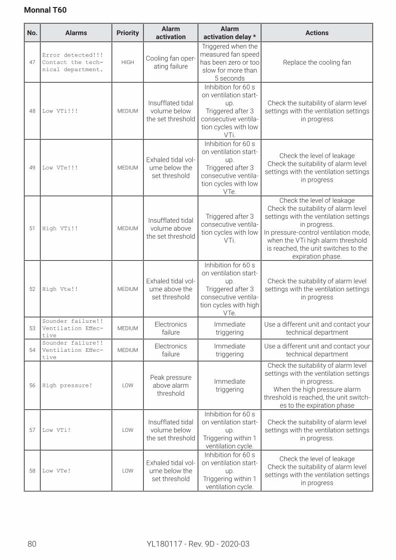
80
Monnal T60
YL180117 - Rev. 9D - 2020-03
No. Alarms Priority Alarm activation
Alarm activationdelay* Actions
47Error detected!!! Contact the tech-nical department.
HIGH Cooling fan oper-ating failure
Triggered when the measured fan speed has been zero or too slow for more than
5 seconds
Replace the cooling fan
48 Low VTi!!! MEDIUMInsufflated tidal volume below
the set threshold
Inhibitionfor60 son ventilation start-
up.Triggered after 3
consecutive ventila-tion cycles with low
VTi.
Check the suitability of alarm level settings with the ventilation settings
in progress
49 Low VTe!!! MEDIUMExhaled tidal vol-ume below the set threshold
Inhibitionfor60 son ventilation start-
up.Triggered after 3
consecutive ventila-tion cycles with low
VTe.
Check the level of leakageCheck the suitability of alarm level
settings with the ventilation settings in progress
51 High VTi!! MEDIUMInsufflated tidal volume above
the set threshold
Triggered after 3 consecutive ventila-tion cycles with low
VTi.
Check the level of leakageCheck the suitability of alarm level
settings with the ventilation settings in progress.
In pressure-control ventilation mode, when the VTi high alarm threshold is reached, the unit switches to the
expiration phase.
52 High Vte!! MEDIUMExhaled tidal vol-ume above the set threshold
Inhibitionfor60 son ventilation start-
up.Triggered after 3
consecutive ventila-tion cycles with high
VTe.
Check the suitability of alarm level settings with the ventilation settings
in progress
53Sounder failure!! Ventilation Effec-tive
MEDIUM Electronics failure
Immediate triggering
Use a different unit and contact your technical department
54Sounder failure!! Ventilation Effec-tive
MEDIUM Electronics failure
Immediate triggering
Use a different unit and contact your technical department
56 High pressure! LOWPeak pressure above alarm
threshold
Immediate triggering
Check the suitability of alarm level settings with the ventilation settings
in progress.When the high pressure alarm
threshold is reached, the unit switch-es to the expiration phase
57 Low VTi! LOWInsufflated tidal volume below
the set threshold
Inhibitionfor60 son ventilation start-
up.Triggering within 1 ventilation cycle.
Check the suitability of alarm level settings with the ventilation settings
in progress.
58 Low VTe! LOWExhaled tidal vol-ume below the set threshold
Inhibitionfor60 son ventilation start-
up.Triggering within 1 ventilation cycle.
Check the level of leakageCheck the suitability of alarm level
settings with the ventilation settings in progress
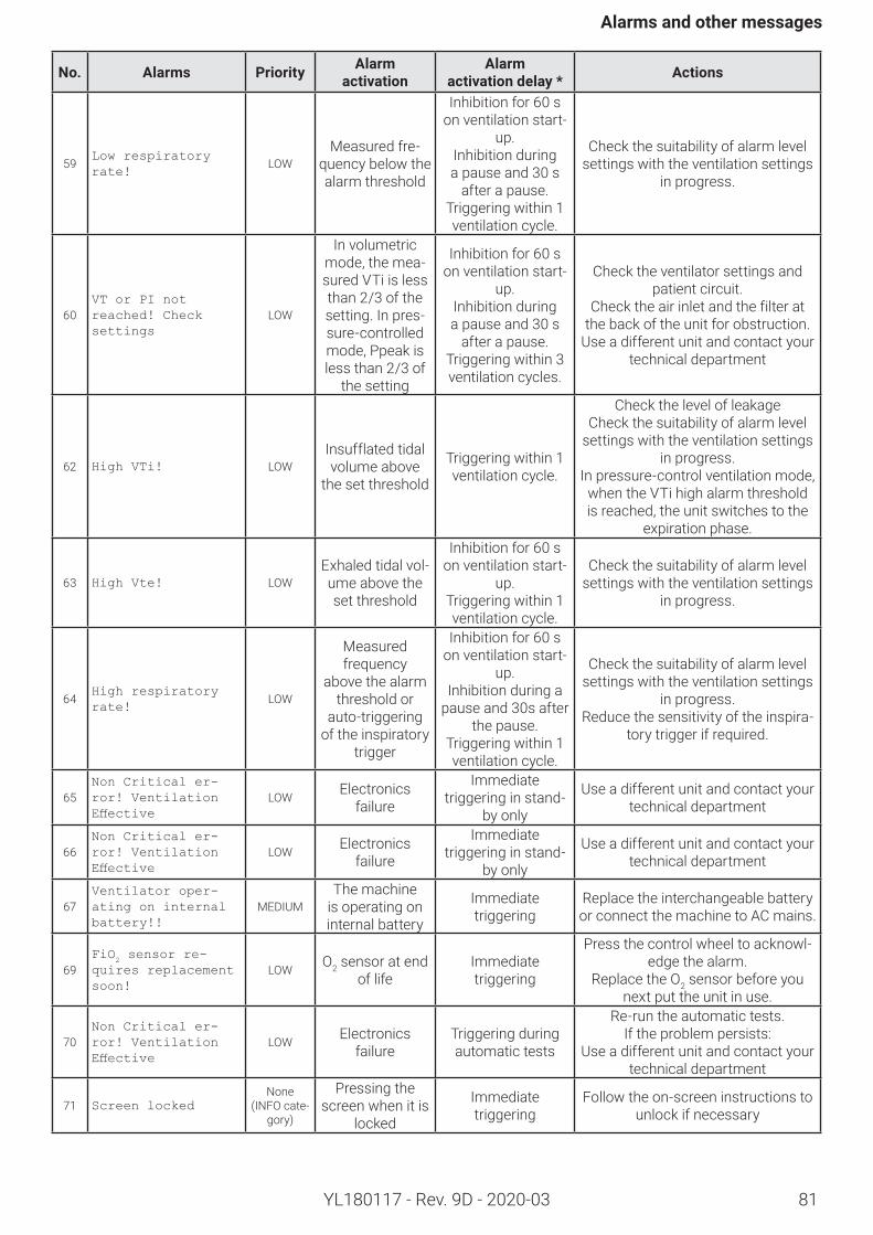
81
Alarmsandothermessages
YL180117 - Rev. 9D - 2020-03
No. Alarms Priority Alarm activation
Alarm activationdelay* Actions
59Low respiratory rate!
LOWMeasured fre-
quency below the alarm threshold
Inhibitionfor60 son ventilation start-
up.Inhibition during a pause and 30 s
after a pause.Triggering within 1 ventilation cycle.
Check the suitability of alarm level settings with the ventilation settings
in progress.
60VT or PI not reached! Check settings
LOW
In volumetric mode, the mea-sured VTi is less than 2/3 of the setting. In pres-sure-controlled mode, Ppeak is less than 2/3 of
the setting
Inhibitionfor60 son ventilation start-
up. Inhibition during a pause and 30 s
after a pause.Triggering within 3 ventilation cycles.
Check the ventilator settings and patient circuit.
Check the air inlet and the filter at the back of the unit for obstruction.
Use a different unit and contact your technical department
62 High VTi! LOWInsufflated tidal volume above
the set threshold
Triggering within 1 ventilation cycle.
Check the level of leakageCheck the suitability of alarm level
settings with the ventilation settings in progress.
In pressure-control ventilation mode, when the VTi high alarm threshold is reached, the unit switches to the
expiration phase.
63 High Vte! LOWExhaled tidal vol-ume above the set threshold
Inhibitionfor60 son ventilation start-
up.Triggering within 1 ventilation cycle.
Check the suitability of alarm level settings with the ventilation settings
in progress.
64High respiratory rate!
LOW
Measured frequency
above the alarm threshold or
auto-triggering of the inspiratory
trigger
Inhibitionfor60 son ventilation start-
up.Inhibition during a
pause and 30s after the pause.
Triggering within 1 ventilation cycle.
Check the suitability of alarm level settings with the ventilation settings
in progress.Reduce the sensitivity of the inspira-
tory trigger if required.
65Non Critical er-ror! Ventilation Effective
LOW Electronics failure
Immediate triggering in stand-
by only
Use a different unit and contact your technical department
66Non Critical er-ror! Ventilation Effective
LOW Electronics failure
Immediate triggering in stand-
by only
Use a different unit and contact your technical department
67Ventilator oper-ating on internal battery!!
MEDIUMThe machine
is operating on internal battery
Immediate triggering
Replace the interchangeable battery or connect the machine to AC mains.
69FiO
2 sensor re-
quires replacement soon!
LOW O2 sensor at end of life
Immediate triggering
Press the control wheel to acknowl-edge the alarm.
Replace the O2 sensor before you next put the unit in use.
70Non Critical er-ror! Ventilation Effective
LOW Electronics failure
Triggering during automatic tests
Re-run the automatic tests.If the problem persists:
Use a different unit and contact your technical department
71 Screen locked None
(INFO cate-gory)
Pressing the screen when it is
locked
Immediate triggering
Follow the on-screen instructions to unlock if necessary
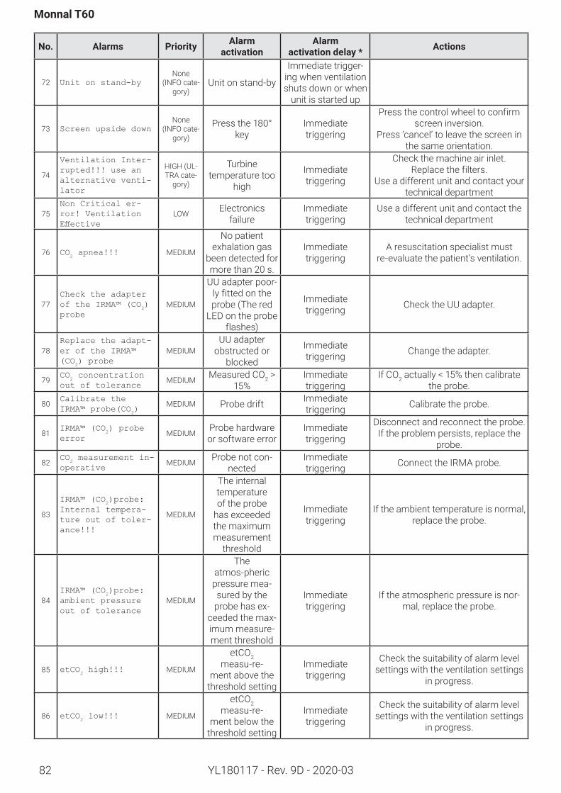
82
Monnal T60
YL180117 - Rev. 9D - 2020-03
No. Alarms Priority Alarm activation
Alarm activationdelay* Actions
72 Unit on stand-byNone
(INFO cate-gory)
Unit on stand-by
Immediate trigger-ing when ventilation shuts down or when
unit is started up
73 Screen upside downNone
(INFO cate-gory)
Press the 180° key
Immediate triggering
Press the control wheel to confirm screen inversion.
Press ‘cancel’ to leave the screen in the same orientation.
74
Ventilation Inter-rupted!!! use an alternative venti-lator
HIGH (UL-TRA cate-
gory)
Turbine temperature too
high
Immediate triggering
Check the machine air inlet.Replace the filters.
Use a different unit and contact your technical department
75Non Critical er-ror! Ventilation Effective
LOW Electronics failure
Immediate triggering
Use a different unit and contact the technical department
76 CO2 apnea!!! MEDIUM
No patient exhalation gas
been detected for more than 20 s.
Immediate triggering
A resuscitation specialist must re-evaluate the patient’s ventilation.
77Check the adapter of the IRMA™ (CO
2)
probeMEDIUM
UU adapter poor-ly fitted on the probe (The red
LED on the probe flashes)
Immediate triggering Check the UU adapter.
78Replace the adapt-er of the IRMA™ (CO
2) probe
MEDIUMUU adapter
obstructed or blocked
Immediate triggering Change the adapter.
79CO
2 concentration
out of toleranceMEDIUM Measured CO2 >
15%Immediate triggering
If CO2 actually < 15% then calibrate the probe.
80Calibrate the IRMA™ probe(CO
2)
MEDIUM Probe drift Immediate triggering Calibrate the probe.
81IRMA™ (CO
2) probe
errorMEDIUM Probe hardware
or software errorImmediate triggering
Disconnect and reconnect the probe. If the problem persists, replace the
probe.
82CO
2 measurement in-
operativeMEDIUM Probe not con-
nectedImmediate triggering Connect the IRMA probe.
83
IRMA™ (CO2)probe:
Internal tempera-ture out of toler-ance!!!
MEDIUM
The internal temperature of the probe
has exceeded the maximum measurement
threshold
Immediate triggering
If the ambient temperature is normal, replace the probe.
84IRMA™ (CO
2)probe:
ambient pressure out of tolerance
MEDIUM
The atmos-pheric pressure mea-sured by the
probe has ex-ceeded the max-imum measure-ment threshold
Immediate triggering
If the atmospheric pressure is nor-mal, replace the probe.
85 etCO2 high!!! MEDIUM
etCO2 measu-re-
ment above the threshold setting
Immediate triggering
Check the suitability of alarm level settings with the ventilation settings
in progress.
86 etCO2 low!!! MEDIUM
etCO2 measu-re-
ment below the threshold setting
Immediate triggering
Check the suitability of alarm level settings with the ventilation settings
in progress.
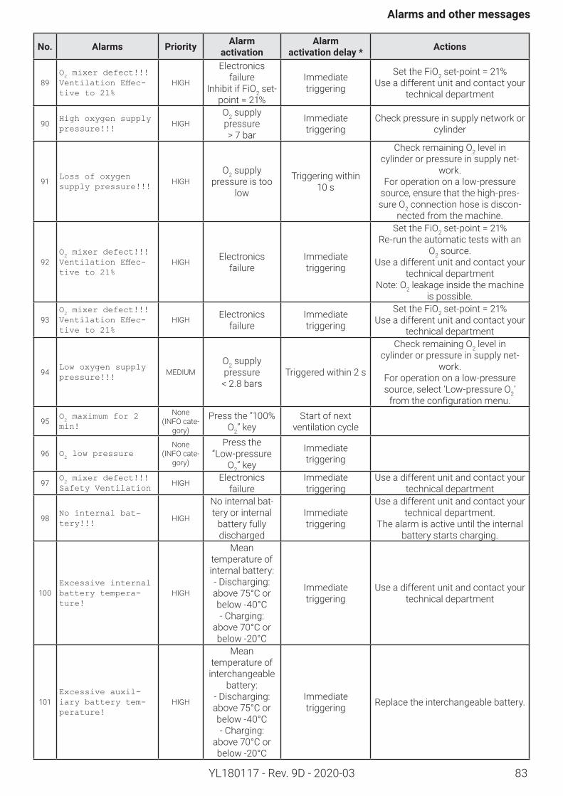
83
Alarmsandothermessages
YL180117 - Rev. 9D - 2020-03
No. Alarms Priority Alarm activation
Alarm activationdelay* Actions
89O2 mixer defect!!!
Ventilation Effec-tive to 21%
HIGH
Electronics failure
Inhibit if FiO2 set-point=21%
Immediate triggering
Set the FiO2set-point=21%Use a different unit and contact your
technical department
90High oxygen supply pressure!!!
HIGHO2 supply pressure > 7 bar
Immediate triggering
Check pressure in supply network or cylinder
91Loss of oxygen supply pressure!!!
HIGHO2 supply
pressure is too low
Triggering within 10 s
Check remaining O2 level in cylinder or pressure in supply net-
work.For operation on a low-pressure
source, ensure that the high-pres-sure O2 connection hose is discon-
nected from the machine.
92O2 mixer defect!!!
Ventilation Effec-tive to 21%
HIGH Electronics failure
Immediate triggering
Set the FiO2set-point=21%Re-run the automatic tests with an
O2 source.Use a different unit and contact your
technical departmentNote: O2 leakage inside the machine
is possible.
93O2 mixer defect!!!
Ventilation Effec-tive to 21%
HIGH Electronics failure
Immediate triggering
Set the FiO2set-point=21%Use a different unit and contact your
technical department
94Low oxygen supply pressure!!!
MEDIUMO2 supply pressure
< 2.8 barsTriggered within 2 s
Check remaining O2 level in cylinder or pressure in supply net-
work.For operation on a low-pressure source, select ‘Low-pressure O2’
from the configuration menu.
95O2 maximum for 2
min!
None(INFO cate-
gory)
Press the “100% O2” key
Start of next ventilation cycle
96 O2 low pressure
None(INFO cate-
gory)
Press the “Low-pressure
O2” key
Immediate triggering
97O2 mixer defect!!!
Safety Ventilation HIGH Electronics
failureImmediate triggering
Use a different unit and contact your technical department
98No internal bat-tery!!!
HIGH
No internal bat-tery or internal
battery fully discharged
Immediate triggering
Use a different unit and contact your technical department.
The alarm is active until the internal battery starts charging.
100Excessive internal battery tempera-ture!
HIGH
Mean temperature of internal battery:- Discharging: above 75°C or below -40°C- Charging:
above 70°C or below -20°C
Immediate triggering
Use a different unit and contact your technical department
101Excessive auxil-iary battery tem-perature!
HIGH
Mean temperature of
interchangeable battery:
- Discharging: above 75°C or below -40°C- Charging:
above 70°C or below -20°C
Immediate triggering Replace the interchangeable battery.
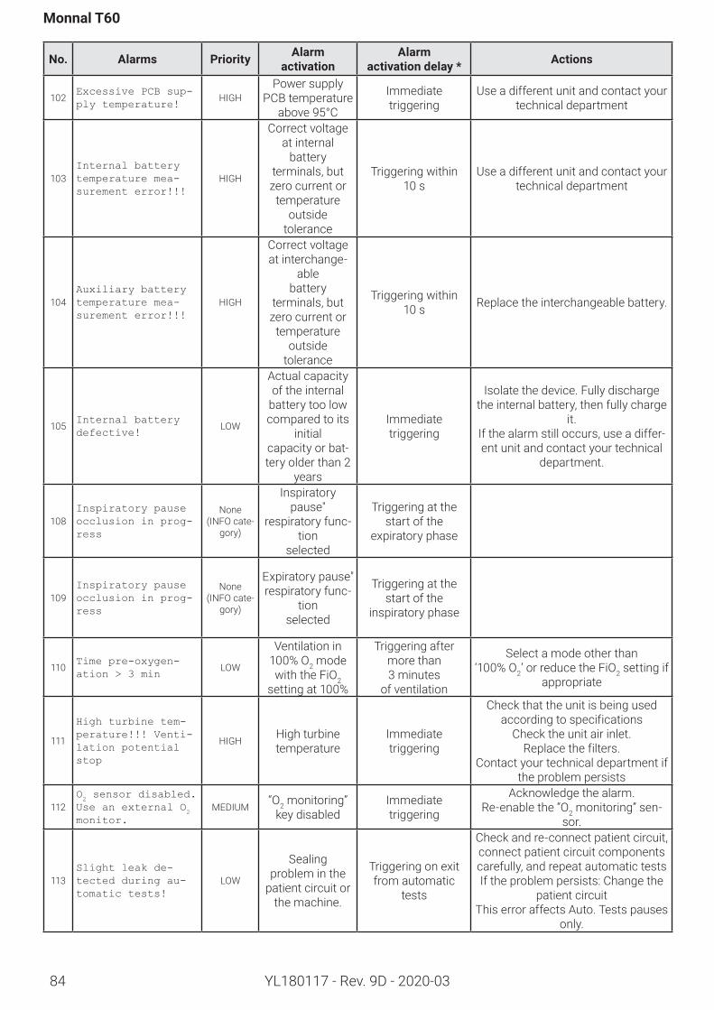
84
Monnal T60
YL180117 - Rev. 9D - 2020-03
No. Alarms Priority Alarm activation
Alarm activationdelay* Actions
102Excessive PCB sup-ply temperature!
HIGHPower supply
PCB temperature above 95°C
Immediate triggering
Use a different unit and contact your technical department
103Internal battery temperature mea-surement error!!!
HIGH
Correct voltage at internal
battery terminals, but zero current or
temperature outside
tolerance
Triggering within 10 s
Use a different unit and contact your technical department
104Auxiliary battery temperature mea-surement error!!!
HIGH
Correct voltage at interchange-
able battery
terminals, but zero current or
temperature outside
tolerance
Triggering within 10 s Replace the interchangeable battery.
105Internal battery defective!
LOW
Actual capacity of the internal
battery too low compared to its
initial capacity or bat-tery older than 2
years
Immediate triggering
Isolate the device. Fully discharge the internal battery, then fully charge
it.If the alarm still occurs, use a differ-ent unit and contact your technical
department.
108Inspiratory pause occlusion in prog-ress
None(INFO cate-
gory)
Inspiratory pause"
respiratory func-tion
selected
Triggering at the start of the
expiratory phase
109Inspiratory pause occlusion in prog-ress
None(INFO cate-
gory)
Expiratory pause" respiratory func-
tion selected
Triggering at the start of the
inspiratory phase
110Time pre-oxygen-ation > 3 min
LOW
Ventilation in 100% O2 mode with the FiO2
setting at 100%
Triggering after more than 3 minutes
of ventilation
Select a mode other than ‘100% O2’ or reduce the FiO2 setting if
appropriate
111
High turbine tem-perature!!! Venti-lation potential stop
HIGH High turbine temperature
Immediate triggering
Check that the unit is being used according to specifications
Check the unit air inlet.Replace the filters.
Contact your technical department if the problem persists
112O2 sensor disabled.
Use an external O2
monitor.MEDIUM “O2 monitoring”
key disabledImmediate triggering
Acknowledge the alarm.Re-enable the “O2 monitoring” sen-
sor.
113Slight leak de-tected during au-tomatic tests!
LOW
Sealing problem in the
patient circuit or the machine.
Triggering on exit from automatic
tests
Check and re-connect patient circuit, connect patient circuit components carefully, and repeat automatic testsIf the problem persists: Change the
patient circuitThis error affects Auto. Tests pauses
only.
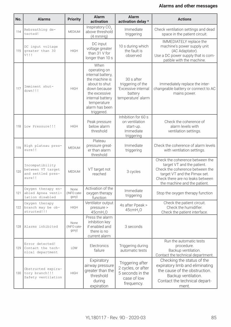
85
Alarmsandothermessages
YL180117 - Rev. 9D - 2020-03
No. Alarms Priority Alarm activation
Alarm activationdelay* Actions
114Rebreathing de-tected!
MEDIUMInspiratory CO2 above threshold
(4 mmHg)
Immediate triggering
Check ventilation settings and dead space in the patient circuit.
115DC input voltage greater than 30 V!!!
HIGH
DC input voltage greater than 31 V for
longer than 10 s
10 s during which the fault is observed
IMMEDIATELY replace the machine’s power supply unit
(AC Adaptator).Use a DC power supply that is com-
patible with the machine.
117Imminent shut-down!!!
HIGH
When operating on
internal battery, the machine is about to shut
down because the excessive
internal battery temperature
alarm has been triggered.
30 s after triggering of the
‘Excessive internal battery
temperature’ alarm
Immediately replace the inter-changeable battery or connect to AC
mains power.
118 Low Pressure!!! HIGHPeak pressure below alarm
threshold
Inhibition for 60 s on ventilation
start-up.Immediate triggering
Check the coherence of alarm levels with
ventilation settings.
119High plateau pres-sure!!
MEDIUM
Plateau pressure great-er than alarm
threshold
Immediate triggering
Check the coherence of alarm levels with ventilation settings.
120
Incompatibility between VT target and settled pres-sure!!
MEDIUM VT target not reached 3 cycles
Check the coherence between the target VT and the patient.
Check the coherence between the target VT and the Pimax set.
Check there are no leaks between the machine and the patient.
121Oxygen therapy en-abled Apnea venti-lation disabled
None(INFO cate-
gory)
Activation of the oxygen therapy
function
Immediate triggering Stop the oxygen therapy function
122Oxygen therapy branch may be ob-structed!!!
HIGHVentilator output
pressure > 45cmH2O
4s after Ppeak > 45cmH2O
Check the patient circuit. Check the humidifier.
Check the patient interface.
128 Alarms inhibitedNone
(INFO cate-gory)
Press the alarm inhibition key if enabled and
there is no current alarm
3 seconds
129Error detected!Contact the tech-nical department
LOW Electronics failure
Triggering during automatic tests
Run the automatic tests procedure.
Backup ventilation. Contact the technical department.
130Obstructed expira-tory branch!!!Safety ventilation
HIGH
Expiratory airway pressure greater than the
threshold during
expiration
Triggering after 2 cycles, or after 5 seconds in the
case of low frequency.
Checking the status of the expiratory limb and eliminating the cause of the obstruction.
Backup ventilation. Contact the technical depart-
ment.
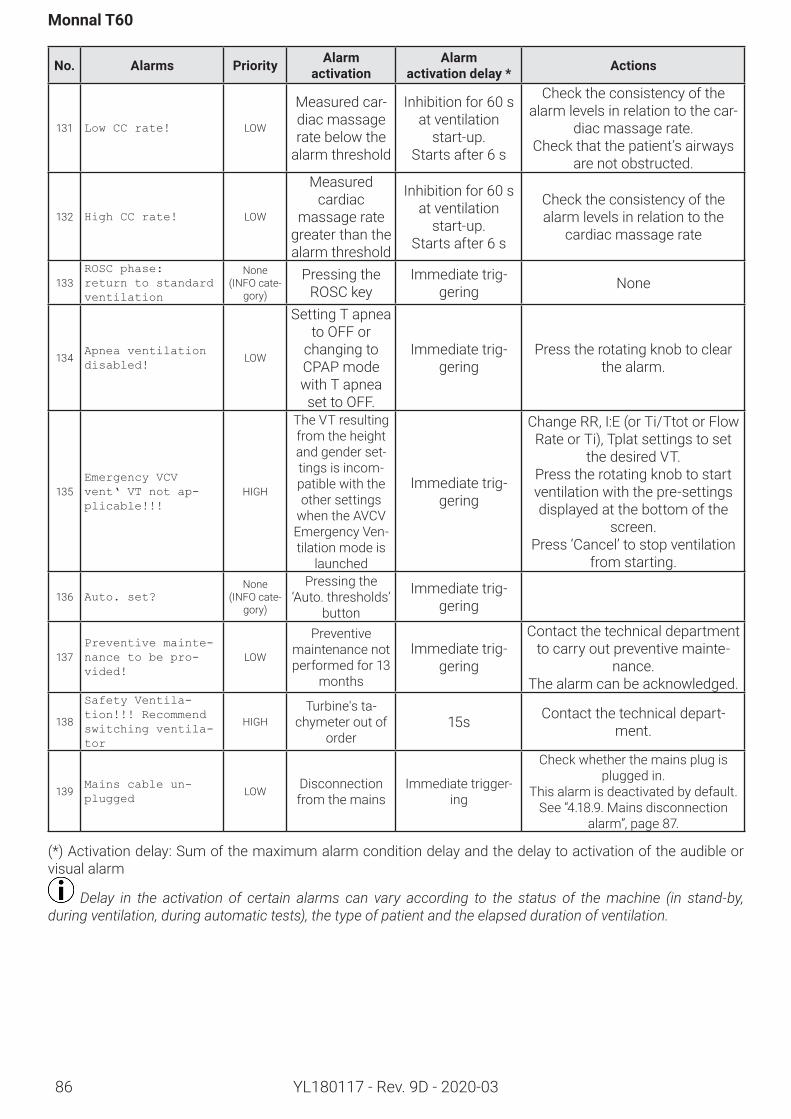
86
Monnal T60
YL180117 - Rev. 9D - 2020-03
No. Alarms Priority Alarm activation
Alarm activationdelay* Actions
131 Low CC rate! LOW
Measured car-diac massage rate below the
alarm threshold
Inhibition for 60 s at ventilation
start-up.Startsafter6 s
Check the consistency of the alarm levels in relation to the car-
diac massage rate.Check that the patient’s airways
are not obstructed.
132 High CC rate! LOW
Measured cardiac
massage rate greater than the alarm threshold
Inhibition for 60 s at ventilation
start-up.Startsafter6 s
Check the consistency of the alarm levels in relation to the
cardiac massage rate
133ROSC phase:return to standard ventilation
None(INFO cate-
gory)
Pressing the ROSC key
Immediate trig-gering None
134Apnea ventilation disabled!
LOW
Setting T apnea to OFF or
changing to CPAP mode with T apnea set to OFF.
Immediate trig-gering
Press the rotating knob to clear the alarm.
135Emergency VCV vent‘ VT not ap-plicable!!!
HIGH
The VT resulting from the height and gender set-tings is incom-patible with the other settings
when the AVCV Emergency Ven-tilation mode is
launched
Immediate trig-gering
Change RR, I:E (or Ti/Ttot or Flow Rate or Ti), Tplat settings to set
the desired VT. Press the rotating knob to start ventilation with the pre-settings displayed at the bottom of the
screen.Press ‘Cancel’ to stop ventilation
from starting.
136 Auto. set?None
(INFO cate-gory)
Pressing the ‘Auto. thresholds’
button
Immediate trig-gering
137Preventive mainte-nance to be pro-vided!
LOW
Preventive maintenance not performed for 13
months
Immediate trig-gering
Contact the technical department to carry out preventive mainte-
nance.The alarm can be acknowledged.
138
Safety Ventila-tion!!! Recommend switching ventila-tor
HIGHTurbine's ta-
chymeter out of order
15s Contact the technical depart-ment.
139Mains cable un-plugged
LOW Disconnection from the mains
Immediate trigger-ing
Check whether the mains plug is plugged in.
This alarm is deactivated by default. See “4.18.9. Mains disconnection
alarm”, page 87.
(*) Activation delay: Sum of the maximum alarm condition delay and the delay to activation of the audible or visual alarm
Delay in the activation of certain alarms can vary according to the status of the machine (in stand-by, during ventilation, during automatic tests), the type of patient and the elapsed duration of ventilation.
87
Maintenance
YL180117 - Rev. 9D - 2020-03
6. MaintenanceAccessories can be re-usable (autoclavable) or single-use (disposable).Re-usable elements must be regularly cleaned and sterilized to prevent cross-infection. This procedure, which is mandatory and extremely important, is the responsibility of the user.
6.1. Definitions
Pre-disinfection
Initial treatment to be carried out on soiled objects and equipment in order to reduce the presence of micro-or-ganisms and facilitate subsequent cleaning.
Cleaning
The act of removing all traces of soiling from a place, a surface, or an element.
Sterilization
Total destruction of all germ strains, viruses, and yeasts.A sterilization or disinfection procedure is never possible on dirty or soiled elements.
Acompleteprocedureincludes:
1. Disassembly, pre-disinfection, rinsing and drying2. Cleaning , rinsing and drying3. Disinfection, rinsing and drying, or sterilization4. Reassembly and functional tests
Never use abrasive powders, acetone, or other powerful solvents.
The following instructions have been approved by the manufacturer of the medical equipment as enabling a medical device to be prepared for re-use. It is always the responsibility of the department concerned to ensure that the sterilization procedure actually im-plemented to the equipment, materials and personnel of the reprocessing facility achieves the expected result.This generally requires the validation and routine inspection of procedures.
6.2. RoutineMaintenanceThe surface of the ventilator can be cleaned.Air Liquide Medical Systems recommends the use of Schülke mikrozid universal wipes, ANIOS TSA, or ANIOS SURFA’safe products.It is important to follow the instructions of the product manufacturer, and not to allow any liquid to penetrate inside the unit.
Maintenance must be carried out with the ventilator disconnected from the electrical power supply.
Before cleaning the device, it is necessary to replace the USB cover to prevent liquid from getting into the fan.
6.3. BacteriologicalfilterApplymanufacturerrecommendationsconcerningthefrequencyofreplacementofthebacteriologicalfilter.Refertotheuserinstructionssuppliedwiththefilter.
Reusing single-use accessories or consumables carries the risk of patient cross-contamination.
A clogged bacteriological filter can lead to an increase in inspiratory and expiratory resistance.
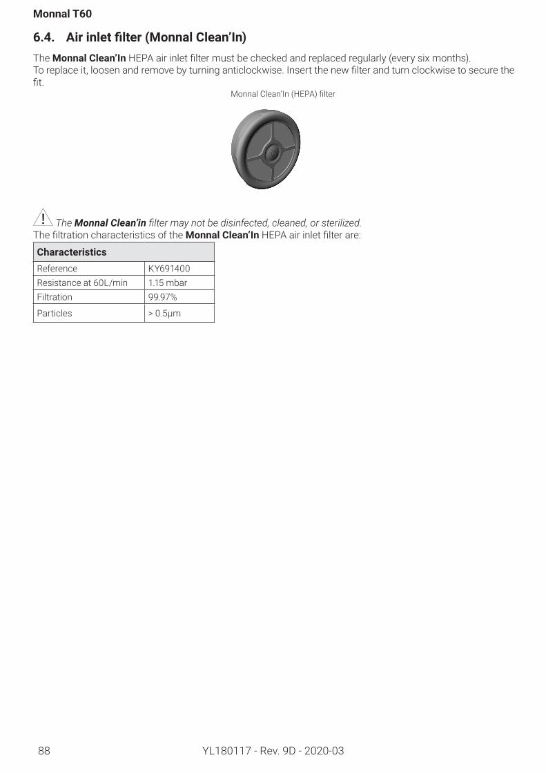
Monnal T60
YL180117 - Rev. 9D - 2020-0388
6.4. Airinletfilter(MonnalClean’In)The MonnalClean’InHEPAairinletfiltermustbecheckedandreplacedregularly(everysixmonths).Toreplaceit,loosenandremovebyturninganticlockwise.Insertthenewfilterandturnclockwisetosecurethefit.
MonnalClean’In(HEPA)filter
The Monnal Clean’in filter may not be disinfected, cleaned, or sterilized.ThefiltrationcharacteristicsoftheMonnalClean’InHEPAairinletfilterare:
CharacteristicsReference KY691400Resistance at 60L/min 1.15 mbarFiltration 99.97%
Particles > 0.5µm
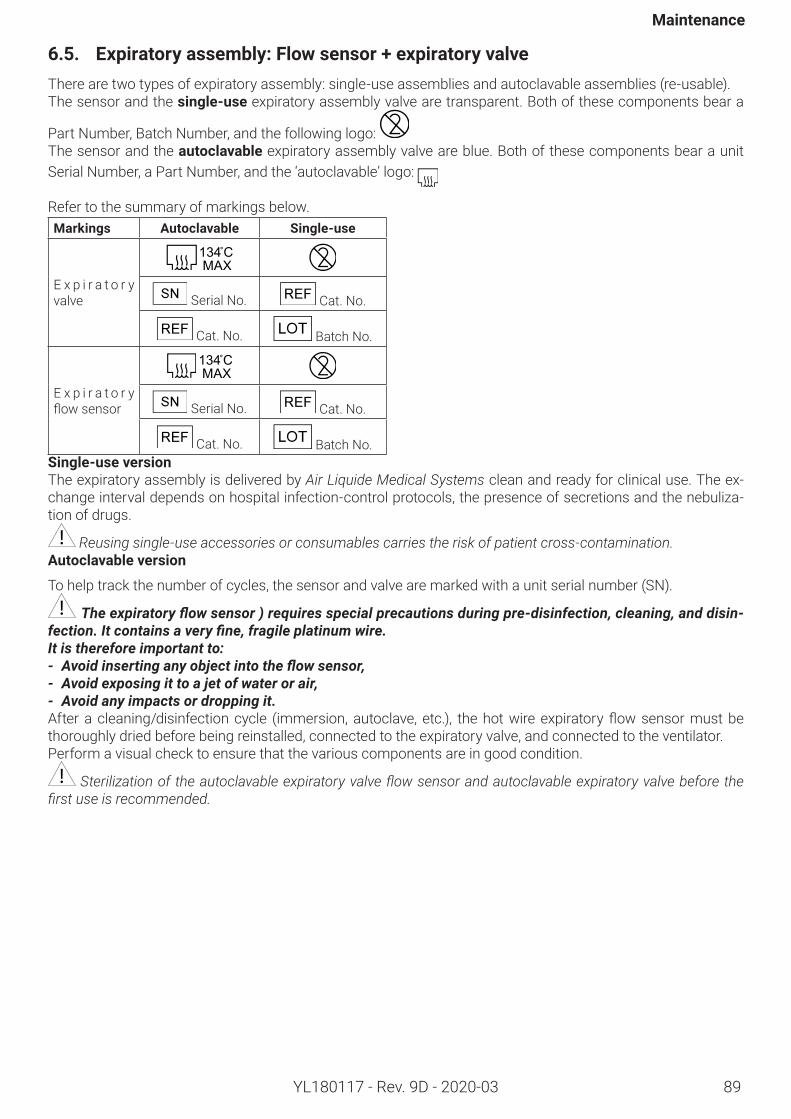
Maintenance
89YL180117 - Rev. 9D - 2020-03
6.5. Expiratoryassembly:Flowsensor+expiratoryvalveThere are two types of expiratory assembly: single-use assemblies and autoclavable assemblies (re-usable). The sensor and the single-use expiratory assembly valve are transparent. Both of these components bear a
Part Number, Batch Number, and the following logo: The sensor and the autoclavable expiratory assembly valve are blue. Both of these components bear a unit Serial Number, a Part Number, and the ‘autoclavable’ logo:
Refer to the summary of markings below.Markings Autoclavable Single-use
E x p i r a t o r y valve
Serial No. Cat. No.
Cat. No. Batch No.
E x p i r a t o r y flowsensor
Serial No. Cat. No.
Cat. No. Batch No.Single-useversionThe expiratory assembly is delivered by Air Liquide Medical Systems clean and ready for clinical use. The ex-change interval depends on hospital infection-control protocols, the presence of secretions and the nebuliza-tion of drugs.
Reusing single-use accessories or consumables carries the risk of patient cross-contamination.Autoclavableversion
To help track the number of cycles, the sensor and valve are marked with a unit serial number (SN).
The expiratory flow sensor ) requires special precautions during pre-disinfection, cleaning, and disin-fection. It contains a very fine, fragile platinum wire. It is therefore important to:- Avoid inserting any object into the flow sensor,- Avoid exposing it to a jet of water or air,- Avoid any impacts or dropping it.Afteracleaning/disinfectioncycle (immersion,autoclave,etc.), thehotwireexpiratoryflowsensormustbethoroughly dried before being reinstalled, connected to the expiratory valve, and connected to the ventilator.Perform a visual check to ensure that the various components are in good condition.
Sterilization of the autoclavable expiratory valve flow sensor and autoclavable expiratory valve before the first use is recommended.
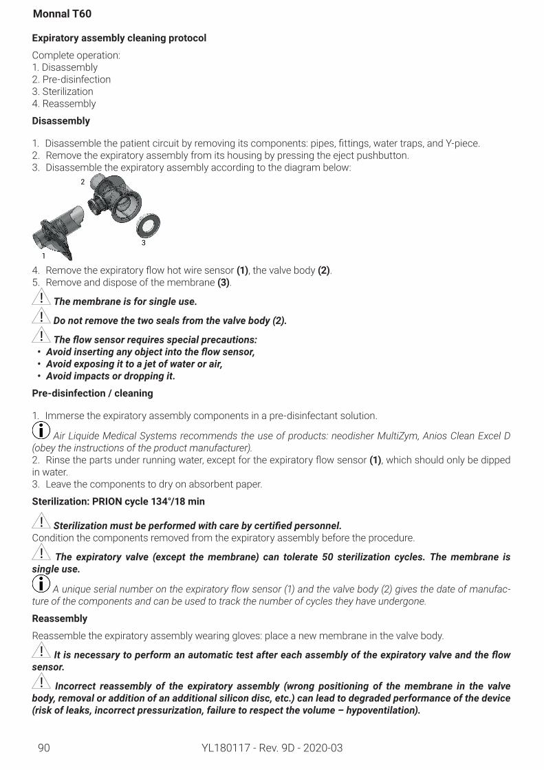
90
Monnal T60
YL180117 - Rev. 9D - 2020-03
Expiratoryassemblycleaningprotocol
Complete operation: 1. Disassembly2. Pre-disinfection3. Sterilization4. Reassembly
Disassembly
1. Disassemblethepatientcircuitbyremovingitscomponents:pipes,fittings,watertraps,andY-piece.2. Remove the expiratory assembly from its housing by pressing the eject pushbutton.3. Disassemble the expiratory assembly according to the diagram below:
1
2
3
4. Removetheexpiratoryflowhotwiresensor(1), the valve body (2).5. Remove and dispose of the membrane (3).
The membrane is for single use.
Do not remove the two seals from the valve body (2).
The flow sensor requires special precautions: • Avoid inserting any object into the flow sensor,• Avoid exposing it to a jet of water or air,• Avoid impacts or dropping it.
Pre-disinfection/cleaning
1. Immerse the expiratory assembly components in a pre-disinfectant solution.
Air Liquide Medical Systems recommends the use of products: neodisher MultiZym, Anios Clean Excel D (obey the instructions of the product manufacturer). 2. Rinsethepartsunderrunningwater,exceptfortheexpiratoryflowsensor(1), which should only be dipped in water.3. Leave the components to dry on absorbent paper.
Sterilization:PRIONcycle134°/18min
Sterilization must be performed with care by certified personnel. Condition the components removed from the expiratory assembly before the procedure.
The expiratory valve (except the membrane) can tolerate 50 sterilization cycles. The membrane is single use.
A unique serial number on the expiratory flow sensor (1) and the valve body (2) gives the date of manufac-ture of the components and can be used to track the number of cycles they have undergone.
Reassembly
Reassemble the expiratory assembly wearing gloves: place a new membrane in the valve body.
It is necessary to perform an automatic test after each assembly of the expiratory valve and the flow sensor.
Incorrect reassembly of the expiratory assembly (wrong positioning of the membrane in the valve body, removal or addition of an additional silicon disc, etc.) can lead to degraded performance of the device (risk of leaks, incorrect pressurization, failure to respect the volume – hypoventilation).
Accessories
91YL180117 - Rev. 9D - 2020-03
7. Accessories
7.1. RegulatoryrequirementsThe accessories used with this ventilator must com-ply with the general requirements of European direc-tive 93/42/CEE, as well as EN 60601-1 and collateral standards.Accessories from the Air Liquide Medical Systems catalogue or included in the accessories kit delivered with the ventilator comply with these requirements. The use of accessories not recommended by Air Liq-uide Medical Systems releases Air Liquide Medical Systems from all liability in the event of an incident. The user is responsible for ensuring that the use of ac-cessories does not affect the safety and the expected performance of the ventilator. The inspiratory and expiratory resistance measure-ments are taken during the automatic tests. In the absence of automatic tests, the resistances retained correspondtothoseoftheventilatorfittedwithastan-dard adult patient circuit and a bacteriological filter(KV103300).
Altering the patient circuit (e.g., addition of a hu-midifier, nebulizer) may lead to variations in the inspira-tory and expiratory resistances. These variations may negatively affect the performance of the ventilator.
If a nebulizer is used, it is necessary to use a filter on the expiratory limb to avoid damage to the expira-tory flow sensor.
Nebulization may increase the resistance of the filters placed in the patient circuit. The filters should be checked frequently for an increase in resistance or blockage.Theprescribermust also ensure that the configura-tion thus obtained, complies with IEC 60601-2-12.
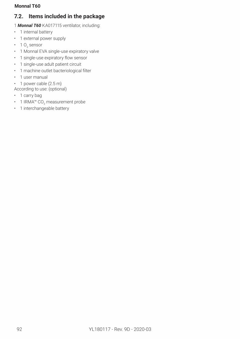
92
Monnal T60
YL180117 - Rev. 9D - 2020-03
7.2. Itemsincludedinthepackage1 Monnal T60 KA017115 ventilator, including:• 1 internal battery• 1 external power supply• 1 O2 sensor • 1 Monnal EVA single-use expiratory valve • 1single-useexpiratoryflowsensor• 1 single-use adult patient circuit • 1machineoutletbacteriologicalfilter• 1 user manual• 1 power cable (2.5 m)According to use: (optional)• 1 carry bag• 1 IRMA™ CO2 measurement probe • 1 interchangeable battery
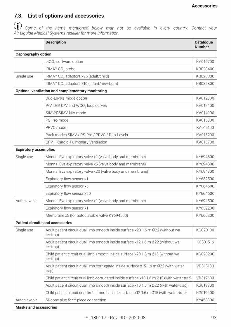
93
Accessories
YL180117 - Rev. 9D - 2020-03
7.3. Listofoptionsandaccessories
Some of the items mentioned below may not be available in every country. Contact your Air Liquide Medical Systems reseller for more information.
Description CatalogueNumber
Capnographyoption
etCO2 software option KA010700
IRMA™ CO2 probe KB020400
Single use IRMA™ CO2 adaptors x25 (adult/child) KB020300
IRMA™ CO2 adaptors x10 (infant/new-born) KB032800
Optionalventilationandcomplementarymonitoring
Duo-Levels mode option KA012300
P/V, D/P, D/V and V/CO2 loop curves KA012400
SIMV/PSIMV-NIV mode KA014900
PS-Pro mode KA015000
PRVC mode KA015100
Pack modes SIMV / PS-Pro / PRVC / Duo-Levels KA015200
CPV – Cardio-Pulmonary Ventilation KA015700
Expiratoryassemblies
Single use Monnal Eva expiratory valve x1 (valve body and membrane) KY694600
Monnal Eva expiratory valve x5 (valve body and membrane) KY694800
Monnal Eva expiratory valve x20 (valve body and membrane) KY694900
Expiratoryflowsensorx1 KY632500
Expiratoryflowsensorx5 KY664500
Expiratoryflowsensorx20 KY664600
Autoclavable Monnal Eva expiratory valve x1 (valve body and membrane) KY694500
Expiratoryflowsensorx1 KY632200
Membrane x5 (for autoclavable valve KY694500) KY665300
Patientcircuitsandaccessories
Single use Adult patient circuit dual limb smooth inside surface x20 1.6 m Ø22 (without wa-ter-trap)
KG020100
Adult patient circuit dual limb smooth inside surface x12 1.6 m Ø22 (without wa-ter-trap)
KG501516
Child patient circuit dual limb smooth inside surface x20 1.5 m Ø15 (without wa-ter-trap)
KG020200
Adult patient circuit dual limb corrugated inside surface x15 1.6 m Ø22 (with water trap)
VD315100
Child patient circuit dual limb corrugated inside surface x10 1.6 m Ø15 (with water trap) VD317600
Adult patient circuit dual limb smooth inside surface x10 1.5 m Ø22 (with water-trap) KG019300
Child patient circuit dual limb smooth inside surface x12 1.6 m Ø15 (with water-trap) KG019400
Autoclavable Silicone plug for Y-piece connection KY453300
Masksandaccessories
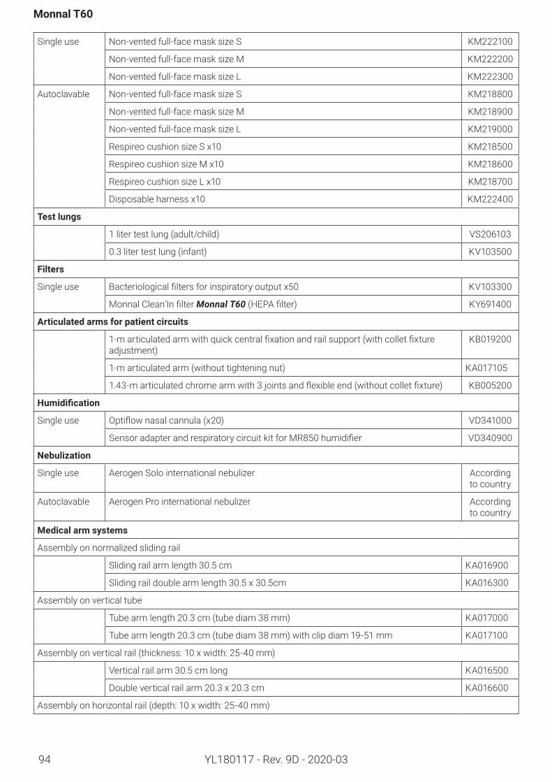
94
Monnal T60
YL180117 - Rev. 9D - 2020-03
Single use Non-vented full-face mask size S KM222100
Non-vented full-face mask size M KM222200
Non-vented full-face mask size L KM222300
Autoclavable Non-vented full-face mask size S KM218800
Non-vented full-face mask size M KM218900
Non-vented full-face mask size L KM219000
Respireo cushion size S x10 KM218500
Respireo cushion size M x10 KM218600
Respireo cushion size L x10 KM218700
Disposable harness x10 KM222400
Testlungs
1 liter test lung (adult/child) VS206103
0.3 liter test lung (infant) KV103500
Filters
Single use Bacteriologicalfiltersforinspiratoryoutputx50 KV103300
MonnalClean’InfilterMonnal T60 (HEPAfilter) KY691400
Articulatedarmsforpatientcircuits
1-marticulatedarmwithquickcentralfixationandrailsupport(withcolletfixtureadjustment)
KB019200
1-m articulated arm (without tightening nut) KA017105
1.43-marticulatedchromearmwith3jointsandflexibleend(withoutcolletfixture) KB005200
Humidification
Single use Optiflownasalcannula(x20) VD341000
SensoradapterandrespiratorycircuitkitforMR850humidifier VD340900
Nebulization
Single use Aerogen Solo international nebulizer According to country
Autoclavable Aerogen Pro international nebulizer According to country
Medicalarmsystems
Assembly on normalized sliding rail
Sliding rail arm length 30.5 cm KA016900
Sliding rail double arm length 30.5 x 30.5cm KA016300
Assembly on vertical tube
Tube arm length 20.3 cm (tube diam 38 mm) KA017000
Tube arm length 20.3 cm (tube diam 38 mm) with clip diam 19-51 mm KA017100
Assembly on vertical rail (thickness: 10 x width: 25-40 mm)
Vertical rail arm 30.5 cm long KA016500
Double vertical rail arm 20.3 x 20.3 cm KA016600
Assembly on horizontal rail (depth: 10 x width: 25-40 mm)
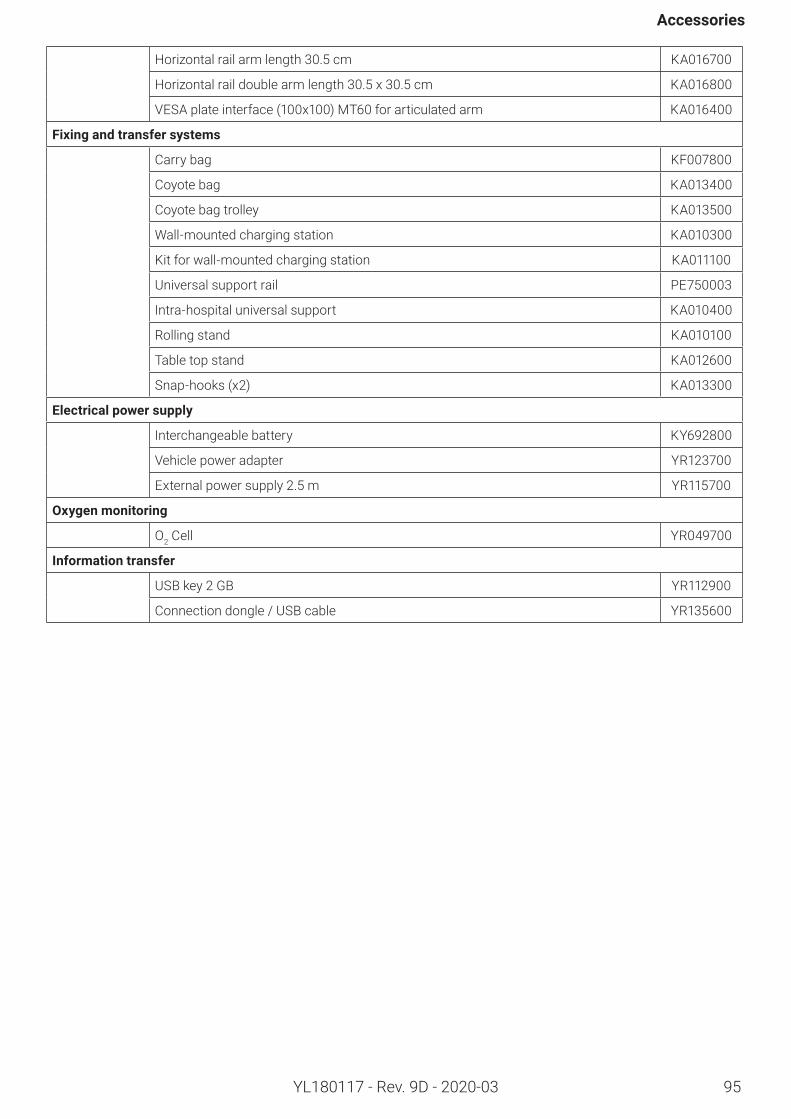
95
Accessories
YL180117 - Rev. 9D - 2020-03
Horizontal rail arm length 30.5 cm KA016700
Horizontal rail double arm length 30.5 x 30.5 cm KA016800
VESA plate interface (100x100) MT60 for articulated arm KA016400
Fixingandtransfersystems
Carry bag KF007800
Coyote bag KA013400
Coyote bag trolley KA013500
Wall-mounted charging station KA010300
Kit for wall-mounted charging station KA011100
Universal support rail PE750003
Intra-hospital universal support KA010400
Rolling stand KA010100
Table top stand KA012600
Snap-hooks (x2) KA013300
Electricalpowersupply
Interchangeable battery KY692800
Vehicle power adapter YR123700
External power supply 2.5 m YR115700
Oxygenmonitoring
O2 Cell YR049700
Informationtransfer
USB key 2 GB YR112900
Connection dongle / USB cable YR135600
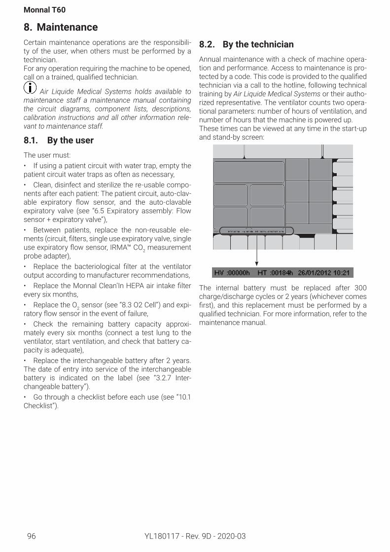
Monnal T60
YL180117 - Rev. 9D - 2020-0396
8. MaintenanceCertain maintenance operations are the responsibili-ty of the user, when others must be performed by a technician. For any operation requiring the machine to be opened, callonatrained,qualifiedtechnician.
Air Liquide Medical Systems holds available to maintenance staff a maintenance manual containing the circuit diagrams, component lists, descriptions, calibration instructions and all other information rele-vant to maintenance staff.
8.1. BytheuserThe user must:• If using a patient circuit with water trap, empty the patient circuit water traps as often as necessary,• Clean, disinfect and sterilize the re-usable compo-nents after each patient: The patient circuit, auto-clav-able expiratory flow sensor, and the auto-clavableexpiratory valve (see “6.5 Expiratory assembly: Flow sensor + expiratory valve”),• Between patients, replace the non-reusable ele-ments(circuit,filters,singleuseexpiratoryvalve,singleuseexpiratoryflowsensor,IRMA™CO2 measurement probe adapter),• Replace the bacteriological filter at the ventilatoroutput according to manufacturer recommendations,• ReplacetheMonnalClean’InHEPAair intakefilterevery six months,• Replace the O2 sensor (see “8.3 O2 Cell”) and expi-ratoryflowsensorintheeventoffailure,• Check the remaining battery capacity approxi-mately every six months (connect a test lung to the ventilator, start ventilation, and check that battery ca-pacity is adequate),• Replace the interchangeable battery after 2 years.The date of entry into service of the interchangeable battery is indicated on the label (see “3.2.7 Inter-changeable battery”).• Go through a checklist before each use (see “10.1 Checklist”).
8.2. BythetechnicianAnnual maintenance with a check of machine opera-tion and performance. Access to maintenance is pro-tectedbyacode.Thiscodeisprovidedtothequalifiedtechnician via a call to the hotline, following technical training by Air Liquide Medical Systems or their autho-rized representative. The ventilator counts two opera-tional parameters: number of hours of ventilation, and number of hours that the machine is powered up.These times can be viewed at any time in the start-up and stand-by screen:
The internal battery must be replaced after 300 charge/discharge cycles or 2 years (whichever comes first), and this replacementmustbeperformedbyaqualifiedtechnician.Formoreinformation,refertothemaintenance manual.
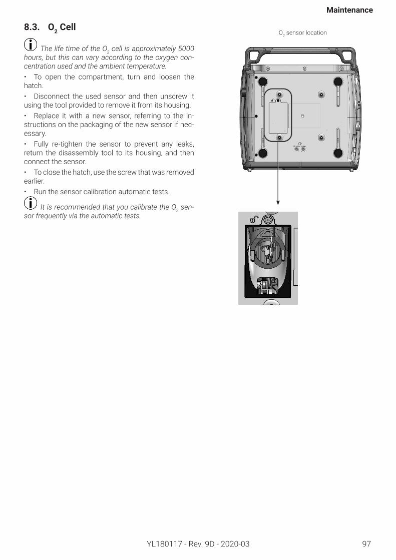
Maintenance
97YL180117 - Rev. 9D - 2020-03
8.3. O2 Cell
The life time of the O2 cell is approximately 5000 hours, but this can vary according to the oxygen con-centration used and the ambient temperature.• To open the compartment, turn and loosen the hatch.• Disconnect the used sensor and then unscrew it using the tool provided to remove it from its housing.• Replace it with a new sensor, referring to the in-structions on the packaging of the new sensor if nec-essary. • Fully re-tighten the sensor to prevent any leaks, return the disassembly tool to its housing, and then connect the sensor.• To close the hatch, use the screw that was removed earlier.• Run the sensor calibration automatic tests.
It is recommended that you calibrate the O2 sen-sor frequently via the automatic tests.
O2 sensor location
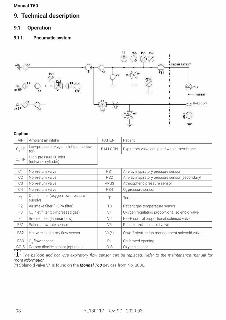
98
Monnal T60
YL180117 - Rev. 9D - 2020-03
9. Technicaldescription
9.1. Operation
9.1.1. Pneumaticsystem
CaptionAIR Ambient air intake PATIENT Patient
O2 LP Low-pressure oxygen inlet (concentra-tor) BALLOON Expiratory valve equipped with a membrane
O2 HP High-pressure O2 inlet (network, cylinder)
C1 Non-return valve PS1 Airway inspiratory pressure sensorC2 Non-return valve PS2 Airway inspiratory pressure sensor (secondary)C3 Non-return valve APS3 Atmospheric pressure sensorC4 Non-return valve PS4 O2 pressure sensor
F1 O2inletfilter(oxygenlowpressuresupply) T Turbine
F2 Airintakefilter(HEPAfilter) TS Patient gas temperature sensorF3 O2inletfilter(compressedgas) V1 Oxygen regulating proportional solenoid valveF4 Bronzefilter(laminarflow) V2 PEEP control proportional solenoid valve
FS1 Patientflowratesensor V3 Pause on/off solenoid valve
FS2 Hotwireexpiratoryflowsensor V4(*) On/off obstruction management solenoid valve
FS3 O2flowsensor R1 Calibrated openingCO2S Carbon dioxide sensor (optional) O2S Oxygen sensor
The balloon and hot wire expiratory flow sensor can be replaced. Refer to the maintenance manual for more information.(*) Solenoid valve V4 is found on the Monnal T60 devices from No. 3000.
BALLOON
Technicaldescription
YL180117 - Rev. 9D - 2020-03 99
9.1.2. Ventilationfunction
The turbine (T) of the ventilator entrains ambient air via the Monnal Clean’In (HEPA) (F2)filterandprovidessufficientcompressionaccordingtothepatient’sflowrequirement and the settings. The compressed gas is then distributed via a pneumatic network according to whether an inspiratory or expiratory phase is being delivered.
Inspiratoryphase
The main component during the inspiratory phase is the turbine(T), which allows the adjustment of:• Flowviatheflowsensor(FS1) when a volume-con-trolled mode is selected,• Pressurized via the pressure sensor (PS1) when the selected mode is pressure-controlled.At the same time, the solenoid valves (V3) and (V2) are open and closed respectively such that the blower pressure is applied to the membrane (M1) of the expi-ratory valve, thus forcing the air sent via the turbine (T) toflowtowardsthepatientonly.
Expiratoryphase
In this phase, the patient exhales the gases inhaled in the previous inspiratory phase, and the unit will reg-ulate flow to a pressure determined by the settings(PEEP).With this in mind, the PEEP control proportional sole-noid valve (V2) regulates the expiration pressure via the pressure sensor (PS1).At the same time, the turbine (T) regulates theflowviatheflowsensor(FS1)foraflow-byrateof5L/min.This flow limits reinhalation and allows quick detec-tion of an inspiratory demand.
During ventilation with leakage, such as NIV, the turbine (T) is liable to increase the rinse flow (flow-by); it then enters an ‘on-demand valve’ mode. The pur-pose of this function is to compensate for leaks in or-der to maintain the PEEP in the circuit.
Safetymechanisms
Venting in the event the machine stopsIn normal operation, the turbine T generates pressure in the inspiratory limb, which keeps the non-return valve C2 closed.If the patient needs to be vented to atmosphere, the turbine shuts down, and no longer generates pressure in the inspiratory limb. Therefore, with every inspira-tory demand, the non-return valve C2 opens, which allows the patient to breathe freely through the device.
Obstruction management
In the event of an obstruction in the expiratory branch, the solenoid valve V4 opens, which depressurizes the patient’s airways. The ventilation continues with zero PEEP. Expiration takes place through solenoid valve V4. The machine tests for the presence of an ob-struction in the expiratory branch at regular intervals. When the obstruction disappears, normal ventilation resumes.In the absence of solenoid valve V4, the pressure in the patient airway can remain elevated. A high priority alarm will be raised in the event of obstruction, with or without a solenoid valve.9.1.3. Air/O2mixture
The O2 concentration of the gases administered to the patient depends on the source connected to the unit. A distinction is made between O2 high pressure oper-ation and O2 low pressure operation.
OperationonanO2highpressurenetwork
For proper operation, the pressure at the O2 inlet termi-nals(O2HP) must be between 2.8 and 6 bar. The O2 is thenfilteredviaF3.The proportional solenoid valve (V1) enriches the mixturewithoxygenbyregulatingtheflowviatheflowsensor (FS3), where the set-point is proportional to theupstreamflowrate(FS1) and depends on the FiO2 setting.
Operation at a network pressure between 1.5 and 2.8 bar or between 6 and 7 bar is possible, but the qual-ity of enrichment may be affected. If the pressure falls below 1.5 bar or goes above 7 bar, the oxygen supply is cut off by the proportional solenoid valve (V1) and an oxygen supply error alarm is triggered.
LowO2pressureoperation
The unit has a “low pressure” connector to operate with a low O2pressuresupplysystem(inletviathefilter(F1)).TheconceptoffinelycontrollingtheO2 pressure that is applied at high pressure is still applied when operating on a low-pressure source: the machine con-tinuously supplies a mixture at the correct FiO2 level. The concentration of the mixture may however not be reached, because this depends on:• The type of low O2 pressure supply system and its settings (the O2flowsuppliedisoftenlow,anditsO2 concentration varies between 90 and 100%)• And the ventilation parameters.
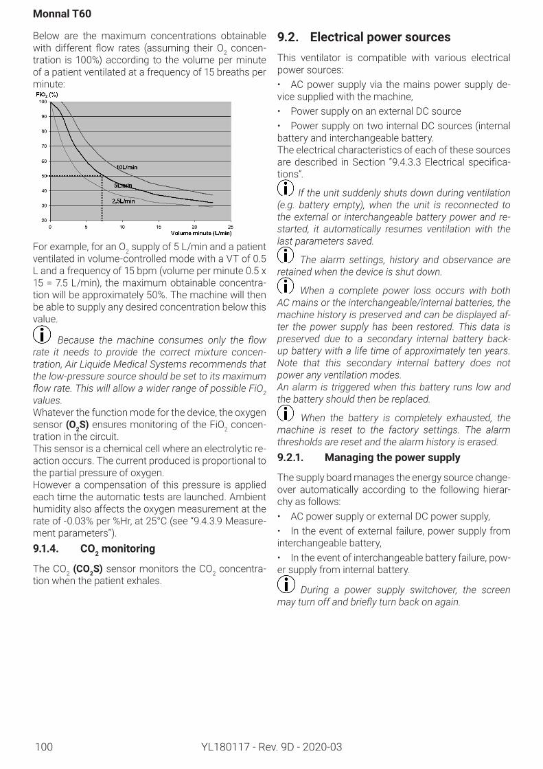
Monnal T60
YL180117 - Rev. 9D - 2020-03100
Below are the maximum concentrations obtainable with different flow rates (assuming their O2 concen-tration is 100%) according to the volume per minute of a patient ventilated at a frequency of 15 breaths per minute:
For example, for an O2 supply of 5 L/min and a patient ventilated in volume-controlled mode with a VT of 0.5 L and a frequency of 15 bpm (volume per minute 0.5 x 15=7.5L/min), themaximumobtainableconcentra-tion will be approximately 50%. The machine will then be able to supply any desired concentration below this value.
Because the machine consumes only the flow rate it needs to provide the correct mixture concen-tration, Air Liquide Medical Systems recommends that the low-pressure source should be set to its maximum flow rate. This will allow a wider range of possible FiO2 values.Whatever the function mode for the device, the oxygen sensor (O2S) ensures monitoring of the FiO2 concen-tration in the circuit.This sensor is a chemical cell where an electrolytic re-action occurs. The current produced is proportional to the partial pressure of oxygen. However a compensation of this pressure is applied each time the automatic tests are launched. Ambient humidity also affects the oxygen measurement at the rate of -0.03% per %Hr, at 25°C (see “9.4.3.9 Measure-ment parameters”).9.1.4. CO2monitoring
The CO2 (CO2S) sensor monitors the CO2 concentra-tion when the patient exhales.
9.2. ElectricalpowersourcesThis ventilator is compatible with various electrical power sources:• AC power supply via the mains power supply de-vice supplied with the machine,• Power supply on an external DC source • Power supply on two internal DC sources (internal battery and interchangeable battery.The electrical characteristics of each of these sources are described in Section “9.4.3.3Electricalspecifica-tions”.
If the unit suddenly shuts down during ventilation (e.g. battery empty), when the unit is reconnected to the external or interchangeable battery power and re-started, it automatically resumes ventilation with the last parameters saved.
The alarm settings, history and observance are retained when the device is shut down.
When a complete power loss occurs with both AC mains or the interchangeable/internal batteries, the machine history is preserved and can be displayed af-ter the power supply has been restored. This data is preserved due to a secondary internal battery back-up battery with a life time of approximately ten years. Note that this secondary internal battery does not power any ventilation modes. An alarm is triggered when this battery runs low and the battery should then be replaced.
When the battery is completely exhausted, the machine is reset to the factory settings. The alarm thresholds are reset and the alarm history is erased.9.2.1. Managingthepowersupply
The supply board manages the energy source change-over automatically according to the following hierar-chy as follows:• AC power supply or external DC power supply,• In the event of external failure, power supply from interchangeable battery,• In the event of interchangeable battery failure, pow-er supply from internal battery.
During a power supply switchover, the screen may turn off and briefly turn back on again.
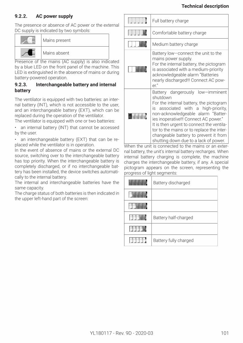
Technicaldescription
YL180117 - Rev. 9D - 2020-03 101
9.2.2. ACpowersupply
The presence or absence of AC power or the external DC supply is indicated by two symbols:
Mains present
Mains absent
Presence of the mains (AC supply) is also indicated by a blue LED on the front panel of the machine. This LED is extinguished in the absence of mains or during battery-powered operation.9.2.3. Interchangeablebatteryandinternalbattery
The ventilator is equipped with two batteries: an inter-nal battery (INT), which is not accessible to the user, and an interchangeable battery (EXT), which can be replaced during the operation of the ventilator. The ventilator is equipped with one or two batteries: • an internal battery (INT) that cannot be accessed by the user. • an interchangeable battery (EXT) that can be re-placed while the ventilator is in operation.In the event of absence of mains or the external DC source, switching over to the interchangeable battery has top priority. When the interchangeable battery is completely discharged, or if no interchangeable bat-tery has been installed, the device switches automati-cally to the internal battery.The internal and interchangeable batteries have the same capacity. The charge status of both batteries is then indicated in the upper left-hand part of the screen:
Full battery charge
Comfortable battery charge
Medium battery charge
Battery low—connect the unit to the mains power supply.For the internal battery, the pictogram is associated with a medium-priority acknowledgeable alarm “Batteries nearly discharged!!! Connect AC pow-er.”Battery dangerously low—imminent shutdown For the internal battery, the pictogram is associated with a high-priority, non-acknowledgeable alarm “Batter-ies inoperative!!! Connect AC power.”It is then urgent to connect the ventila-tor to the mains or to replace the inter-changeable battery to prevent it from shutting down due to a lack of power.
When the unit is connected to the mains or an exter-nal battery, the unit’s internal battery recharges. When internal battery charging is complete, the machine charges the interchangeable battery, if any. A special pictogram appears on the screen, representing the progress of light segments:
Battery discharged
Battery half-charged
Battery fully charged
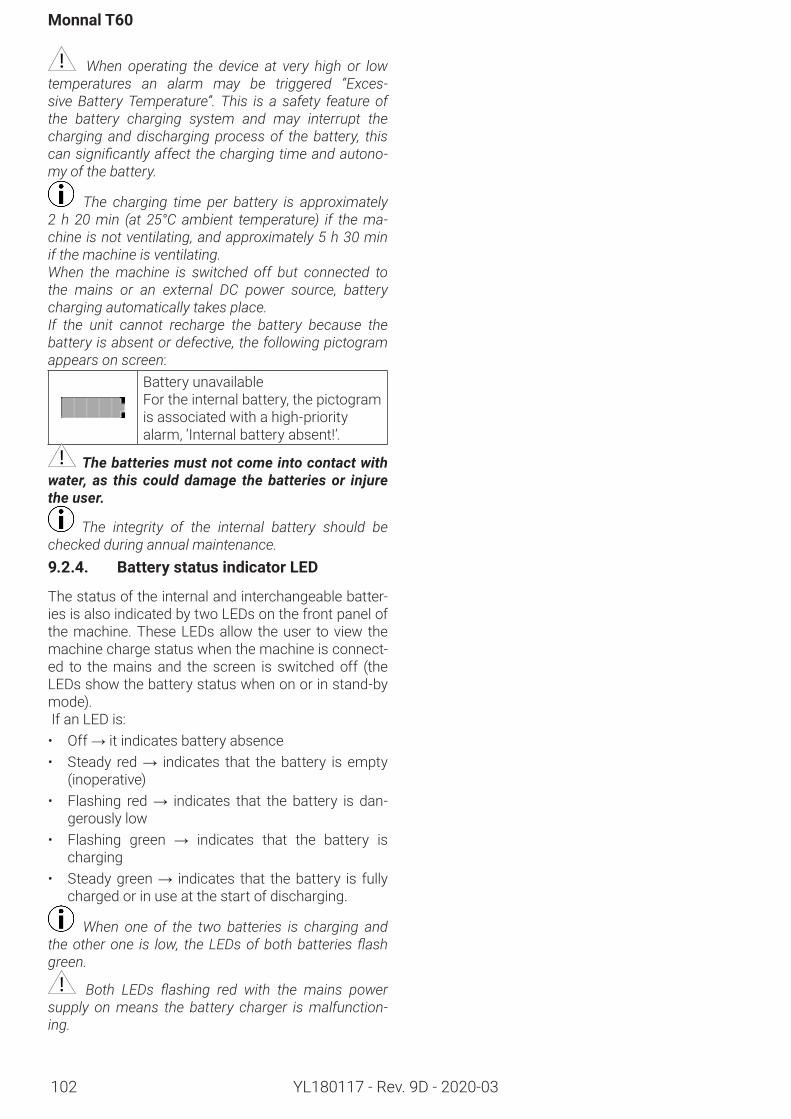
Monnal T60
102 YL180117 - Rev. 9D - 2020-03
When operating the device at very high or low temperatures an alarm may be triggered “Exces-sive Battery Temperature”. This is a safety feature of the battery charging system and may interrupt the charging and discharging process of the battery, this can significantly affect the charging time and autono-my of the battery.
The charging time per battery is approximately 2 h 20 min (at 25°C ambient temperature) if the ma-chine is not ventilating, and approximately 5 h 30 min if the machine is ventilating.When the machine is switched off but connected to the mains or an external DC power source, battery charging automatically takes place.If the unit cannot recharge the battery because the battery is absent or defective, the following pictogram appears on screen:
Battery unavailableFor the internal battery, the pictogram is associated with a high-priority alarm, ‘Internal battery absent!’.
The batteries must not come into contact with water, as this could damage the batteries or injure the user.
The integrity of the internal battery should be checked during annual maintenance.9.2.4. BatterystatusindicatorLED
The status of the internal and interchangeable batter-ies is also indicated by two LEDs on the front panel of the machine. These LEDs allow the user to view the machine charge status when the machine is connect-ed to the mains and the screen is switched off (the LEDs show the battery status when on or in stand-by mode). If an LED is:• Off → it indicates battery absence• Steady red → indicates that the battery is empty
(inoperative)• Flashing red → indicates that the battery is dan-
gerously low• Flashing green → indicates that the battery is
charging• Steady green → indicates that the battery is fully
charged or in use at the start of discharging.
When one of the two batteries is charging and the other one is low, the LEDs of both batteries flash green.
Both LEDs flashing red with the mains power supply on means the battery charger is malfunction-ing.
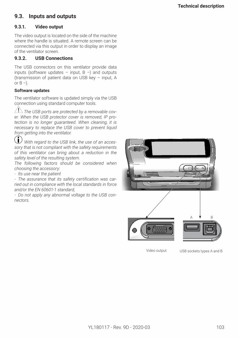
Technicaldescription
103YL180117 - Rev. 9D - 2020-03
9.3. Inputsandoutputs
9.3.1. Videooutput
The video output is located on the side of the machine where the handle is situated. A remote screen can be connected via this output in order to display an image of the ventilator screen.9.3.2. USBConnections
The USB connectors on this ventilator provide data inputs (software updates – input, B –) and outputs (transmission of patient data on USB key – input, A or B –).
Softwareupdates
The ventilator software is updated simply via the USB connection using standard computer tools.
The USB ports are protected by a removable cov-er. When the USB protector cover is removed, IP pro-tection is no longer guaranteed. When cleaning, it is necessary to replace the USB cover to prevent liquid from getting into the ventilator.
With regard to the USB link, the use of an acces-sory that is not compliant with the safety requirements of this ventilator can bring about a reduction in the safety level of the resulting system.The following factors should be considered when choosing the accessory:- Its use near the patient- The assurance that its safety certification was car-ried out in compliance with the local standards in force and/or the EN 60601-1 standard,- Do not apply any abnormal voltage to the USB con-nectors.
A B
Video output USB sockets types A and B
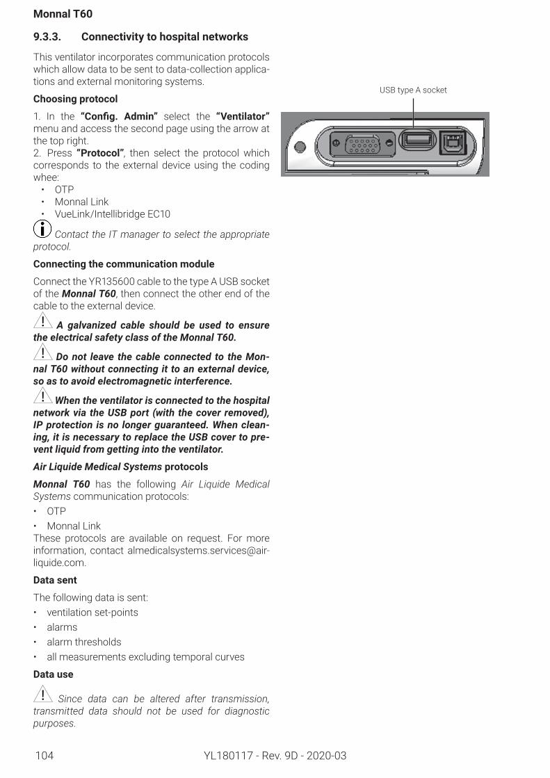
Monnal T60
104 YL180117 - Rev. 9D - 2020-03
9.3.3. Connectivitytohospitalnetworks
This ventilator incorporates communication protocols which allow data to be sent to data-collection applica-tions and external monitoring systems.
Choosingprotocol
1. In the “Config. Admin” select the “Ventilator”menu and access the second page using the arrow at the top right. 2. Press “Protocol”, then select the protocol which corresponds to the external device using the coding whee:• OTP• Monnal Link• VueLink/Intellibridge EC10
Contact the IT manager to select the appropriate protocol.
Connectingthecommunicationmodule
Connect the YR135600 cable to the type A USB socket of the Monnal T60, then connect the other end of the cable to the external device.
A galvanized cable should be used to ensure the electrical safety class of the Monnal T60.
Do not leave the cable connected to the Mon-nal T60 without connecting it to an external device, so as to avoid electromagnetic interference.
When the ventilator is connected to the hospital network via the USB port (with the cover removed), IP protection is no longer guaranteed. When clean-ing, it is necessary to replace the USB cover to pre-vent liquid from getting into the ventilator.
Air Liquide Medical Systemsprotocols
Monnal T60 has the following Air Liquide Medical Systems communication protocols:• OTP• Monnal LinkThese protocols are available on request. For more information, contact [email protected].
Data sent
The following data is sent:• ventilation set-points• alarms• alarm thresholds• all measurements excluding temporal curves
Data use
Since data can be altered after transmission, transmitted data should not be used for diagnostic purposes.
USB type A socket
Technicaldescription
105YL180117 - Rev. 9D - 2020-03
Compatiblecommunicationmodules
Contact Air Liquide Medical Systems to obtain the full list of communication modules compatible with Monnal T60.
A hospital network failure can result in no data being transmitted (alarms and monitoring) to the external system.
Connection to a hospital network supplying other units could give rise to previously unidentified risks to patients, operators or third parties.The user should identify, analyze, evaluate and man-age such risks. Subsequent modifications made to the hospital network could lead to new risks and re-quire further analysis. Modifications to the hospital network include:
• modifications to the configuration of the exter-nal system;• connection of additional units to the external system;• disconnection of units from the external system;• updating of units connected to the external sys-tem;• upgrade of units connected to the external sys-tem.
Monnal T60
YL180117 - Rev. 9D - 2020-03106
9.4. Performanceandcharacteristics
9.4.1. Regulatoryrequirements
Directives
Directive 93/42/EEC Directive 2012/19/EU of the European Parliament and Council Directive concerning Waste Electrical and Electronic Equipment (WEEE).Life time of the Monnal T60 ventilator: 10 years.
Standards
The compliance of Monnal T60 with the essential re-quirements of Directive 93/42 is based on the follow-ing standards: EN ISO 14971 Application of risk management to medical devicesICEI 60601-1 and its amendments | Electromedical devices – Part One: General requirements for safetyIEC 60601-1-2 | Medical electrical equipment - Part 1-2: General requirements for basic safety and essen-tial performance - Collateral standard: Electromagnet-ic compatibility - Requirements and testsEN 60601-1-6 | Medical electrical equipment - Part 1-6: General requirements for basic safety and essen-tial performance - Collateral Standard: Usability ISO 80601-2-12 | Medical electrical equipment - Part 2-12: Specific requirements for basic safety and es-sential performance for pulmonary ventilators for use in intensive careEN 794-3 + A2 | Pulmonary ventilators - Part 3: Spe-cificrecommendationsforemergencyandtransportventilatorsEN 1789 + A1 | Medical vehicles and their equipment - Road ambulancesEN 13718-1 | Medical vehicles and their equipment - Air ambulances - Part 1: Requirements for medical devices used in air ambulancesRTCA-DO160F – Environmental conditions and test procedures for airborne equipment. Sections 7, 8, 20 and 21EN 62304 - Medical device software – Software life cycle processesEN 62366 - Application of usability engineering to medical devices
9.4.2. Recoveryofthecomponentsofthemedicaldevice
Characteristicsofthepackaging
Box for transportation (800 g) and wedge (200 g):• Recycled paper• RecyclableProtective foam (1 kg):• Polyethylene• Recyclable
Methodofrecoveryforconsumableitems
All used consumable items from use of this ventila-tor(thepatientcircuit, thebacteriologicalfilters,etc.)must be collected in the hospital’s appropriate dispos-al channels. The packaging waste for the device and for its accessories must be disposed of in the hospi-tal’s appropriate disposal channels.
Shippingequipment
Air Liquide Medical Systems recommends that the user keep the original packaging.If the medical device is returned, always use the orig-inal packaging. Otherwise, contact your Air Liquide Medical Systems representative to obtain replace-ment packaging.
Equipmentmodifications
It is prohibited to alter the Monnal T60 equipment.
Altering the patient circuit (e.g., addition of a humidifier) may lead to variations in the inspirato-ry and expiratory resistances. These variations may negatively affect the performance of the ventilator.
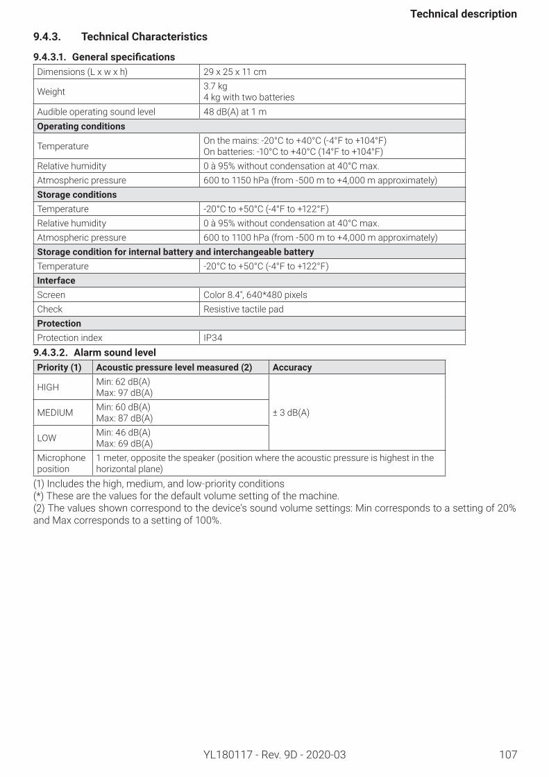
107
Technicaldescription
YL180117 - Rev. 9D - 2020-03
9.4.3. TechnicalCharacteristics
9.4.3.1. GeneralspecificationsDimensions (L x w x h) 29 x 25 x 11 cm
Weight 3.7 kg4 kg with two batteries
Audible operating sound level 48 dB(A) at 1 mOperatingconditions
Temperature On the mains: -20°C to +40°C (-4°F to +104°F)On batteries: -10°C to +40°C (14°F to +104°F)
Relative humidity 0 à 95% without condensation at 40°C max.Atmospheric pressure 600 to 1150 hPa (from -500 m to +4,000 m approximately)StorageconditionsTemperature -20°C to +50°C (-4°F to +122°F)Relative humidity 0 à 95% without condensation at 40°C max.Atmospheric pressure 600 to 1100 hPa (from -500 m to +4,000 m approximately)StorageconditionforinternalbatteryandinterchangeablebatteryTemperature -20°C to +50°C (-4°F to +122°F)InterfaceScreen Color 8.4", 640*480 pixelsCheck Resistive tactile padProtectionProtection index IP349.4.3.2. AlarmsoundlevelPriority(1) Acousticpressurelevelmeasured(2) Accuracy
HIGH Min: 62 dB(A)Max: 97 dB(A)
± 3 dB(A)MEDIUM Min: 60 dB(A)Max: 87 dB(A)
LOW Min: 46 dB(A)Max: 69 dB(A)
Microphone position
1 meter, opposite the speaker (position where the acoustic pressure is highest in the horizontal plane)
(1) Includes the high, medium, and low-priority conditions(*) These are the values for the default volume setting of the machine.(2) The values shown correspond to the device’s sound volume settings: Min corresponds to a setting of 20% and Max corresponds to a setting of 100%.
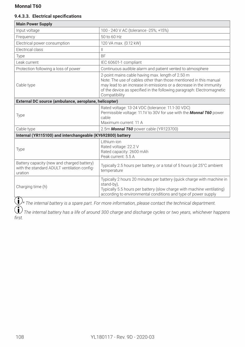
108
Monnal T60
YL180117 - Rev. 9D - 2020-03
9.4.3.3. Electricalspecifications
MainPowerSupplyInput voltage 100 - 240 V AC (tolerance -25%; +15%)Frequency 50 to 60 HzElectrical power consumption 120 VA max. (0.12 kW)Electrical class IIType BFLeak current IEC 60601-1 compliantProtection following a loss of power Continuous audible alarm and patient vented to atmosphere
Cable type
2-point mains cable having max. length of 2.50 mNote: The use of cables other than those mentioned in this manual may lead to an increase in emissions or a decrease in the immunity ofthedeviceasspecifiedinthefollowingparagraph:ElectromagneticCompatibility
ExternalDCsource(ambulance,aeroplane,helicopter)
Type
Rated voltage: 13-24 VDC (tolerance: 11.1-30 VDC) Permissible voltage: 11.1V to 30V for use with the Monnal T60 power cableMaximum current: 11 A
Cable type 2.5m Monnal T60 power cable (YR123700)Internal(YR115100)andinterchangeable(KY692800)battery
Type
Lithium-ionRated voltage: 22.2 VRated capacity: 2600 mAhPeak current: 5.5 A
Battery capacity (new and charged battery) withthestandardADULTventilationconfig-uration
Typically 2.5 hours per battery, or a total of 5 hours (at 25°C ambient temperature
Charging time (h)
Typically 2 hours 20 minutes per battery (quick charge with machine in stand-by), Typically 5.5 hours per battery (slow charge with machine ventilating) according to environmental conditions and type of power supply
* The internal battery is a spare part. For more information, please contact the technical department.
The internal battery has a life of around 300 charge and discharge cycles or two years, whichever happens first.
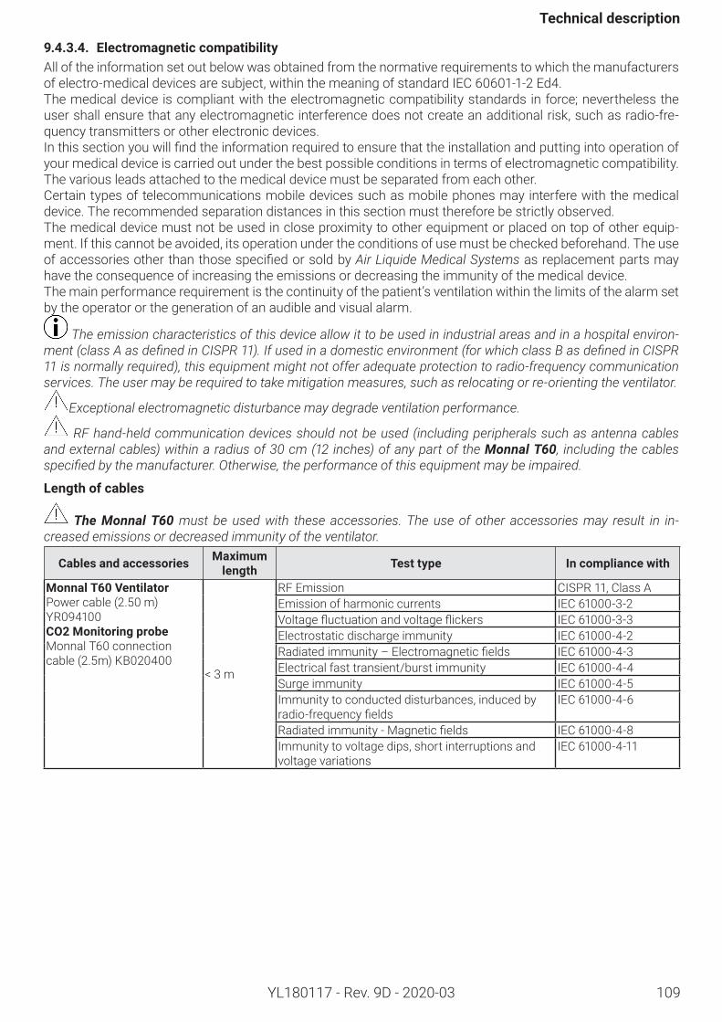
109
Technicaldescription
YL180117 - Rev. 9D - 2020-03
9.4.3.4. ElectromagneticcompatibilityAll of the information set out below was obtained from the normative requirements to which the manufacturers ofelectro-medicaldevicesaresubject,withinthemeaningofstandardIEC 60601-1-2Ed4.The medical device is compliant with the electromagnetic compatibility standards in force; nevertheless the user shall ensure that any electromagnetic interference does not create an additional risk, such as radio-fre-quency transmitters or other electronic devices.Inthissectionyouwillfindtheinformationrequiredtoensurethattheinstallationandputtingintooperationofyour medical device is carried out under the best possible conditions in terms of electromagnetic compatibility. The various leads attached to the medical device must be separated from each other.Certain types of telecommunications mobile devices such as mobile phones may interfere with the medical device. The recommended separation distances in this section must therefore be strictly observed.The medical device must not be used in close proximity to other equipment or placed on top of other equip-ment. If this cannot be avoided, its operation under the conditions of use must be checked beforehand. The use ofaccessoriesotherthanthosespecifiedorsoldbyAir Liquide Medical Systems as replacement parts may have the consequence of increasing the emissions or decreasing the immunity of the medical device.The main performance requirement is the continuity of the patient’s ventilation within the limits of the alarm set by the operator or the generation of an audible and visual alarm.
The emission characteristics of this device allow it to be used in industrial areas and in a hospital environ-ment (class A as defined in CISPR 11). If used in a domestic environment (for which class B as defined in CISPR 11 is normally required), this equipment might not offer adequate protection to radio-frequency communication services. The user may be required to take mitigation measures, such as relocating or re-orienting the ventilator.
Exceptional electromagnetic disturbance may degrade ventilation performance.
RF hand-held communication devices should not be used (including peripherals such as antenna cables and external cables) within a radius of 30 cm (12 inches) of any part of the Monnal T60, including the cables specified by the manufacturer. Otherwise, the performance of this equipment may be impaired.
Lengthofcables
The Monnal T60 must be used with these accessories. The use of other accessories may result in in-creased emissions or decreased immunity of the ventilator.
Cablesandaccessories Maximumlength Testtype Incompliancewith
MonnalT60VentilatorPower cable (2.50 m) YR094100CO2MonitoringprobeMonnal T60 connection cable (2.5m) KB020400
< 3 m
RF Emission CISPR 11, Class AEmission of harmonic currents IEC 61000-3-2Voltagefluctuationandvoltageflickers IEC 61000-3-3Electrostatic discharge immunity IEC 61000-4-2Radiatedimmunity–Electromagneticfields IEC 61000-4-3Electrical fast transient/burst immunity IEC 61000-4-4Surge immunity IEC 61000-4-5Immunity to conducted disturbances, induced by radio-frequencyfields
IEC 61000-4-6
Radiatedimmunity-Magneticfields IEC 61000-4-8Immunity to voltage dips, short interruptions and voltage variations
IEC 61000-4-11
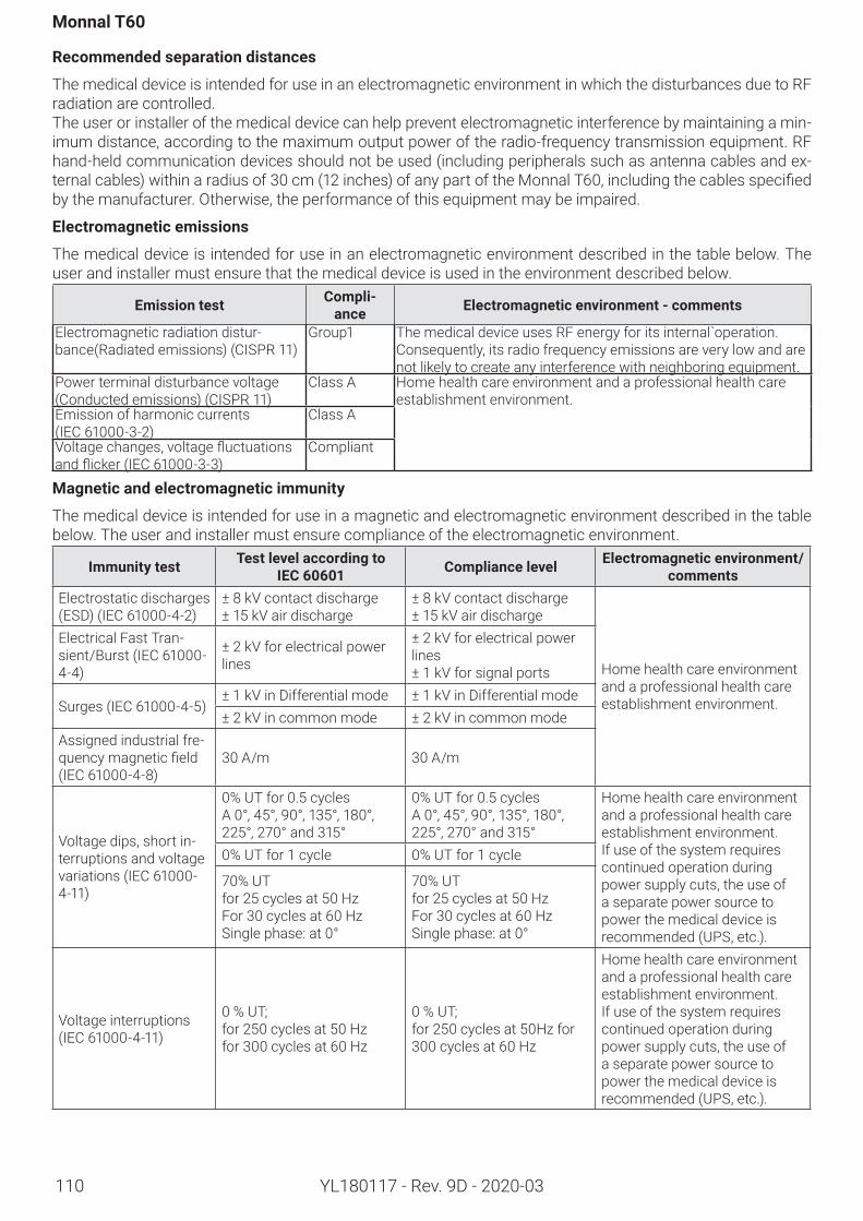
110
Monnal T60
YL180117 - Rev. 9D - 2020-03
Recommendedseparationdistances
The medical device is intended for use in an electromagnetic environment in which the disturbances due to RF radiation are controlled.The user or installer of the medical device can help prevent electromagnetic interference by maintaining a min-imum distance, according to the maximum output power of the radio-frequency transmission equipment. RF hand-held communication devices should not be used (including peripherals such as antenna cables and ex-ternalcables)withinaradiusof30cm(12inches)ofanypartoftheMonnalT60,includingthecablesspecifiedby the manufacturer. Otherwise, the performance of this equipment may be impaired.
Electromagneticemissions
The medical device is intended for use in an electromagnetic environment described in the table below. The user and installer must ensure that the medical device is used in the environment described below.
Emissiontest Compli-ance Electromagneticenvironment-comments
Electromagnetic radiation distur-bance(Radiated emissions) (CISPR 11)
Group1 The medical device uses RF energy for its internal`operation. Consequently, its radio frequency emissions are very low and are not likely to create any interference with neighboring equipment.
Power terminal disturbance voltage (Conducted emissions) (CISPR 11)
Class A Home health care environment and a professional health care establishment environment.
Emission of harmonic currents (IEC 61000-3-2)
Class A
Voltagechanges,voltagefluctuationsandflicker(IEC 61000-3-3)
Compliant
Magneticandelectromagneticimmunity
The medical device is intended for use in a magnetic and electromagnetic environment described in the table below. The user and installer must ensure compliance of the electromagnetic environment.
Immunitytest TestlevelaccordingtoIEC 60601 Compliancelevel Electromagneticenvironment/
commentsElectrostatic discharges (ESD)(IEC 61000-4-2)
± 8 kV contact discharge± 15 kV air discharge
± 8 kV contact discharge± 15 kV air discharge
Home health care environment and a professional health care establishment environment.
Electrical Fast Tran-sient/Burst(IEC 61000-4-4)
± 2 kV for electrical power lines
± 2 kV for electrical power lines± 1 kV for signal ports
Surges(IEC 61000-4-5)± 1 kV in Differential mode ± 1 kV in Differential mode± 2 kV in common mode ± 2 kV in common mode
Assigned industrial fre-quencymagneticfield(IEC 61000-4-8)
30 A/m 30 A/m
Voltage dips, short in-terruptions and voltage variations(IEC 61000-4-11)
0% UT for 0.5 cyclesA 0°, 45°, 90°, 135°, 180°,225°, 270° and 315°
0% UT for 0.5 cyclesA 0°, 45°, 90°, 135°, 180°,225°, 270° and 315°
Home health care environment and a professional health care establishment environment.If use of the system requires continued operation during power supply cuts, the use of a separate power source to power the medical device is recommended (UPS, etc.).
0% UT for 1 cycle 0% UT for 1 cycle
70% UTfor 25 cycles at 50 HzFor 30 cycles at 60 HzSingle phase: at 0°
70% UTfor 25 cycles at 50 HzFor 30 cycles at 60 HzSingle phase: at 0°
Voltage interruptions (IEC 61000-4-11)
0 % UT;for 250 cycles at 50 Hzfor 300 cycles at 60 Hz
0 % UT;for 250 cycles at 50Hz for 300 cycles at 60 Hz
Home health care environment and a professional health care establishment environment.If use of the system requires continued operation during power supply cuts, the use of a separate power source to power the medical device is recommended (UPS, etc.).
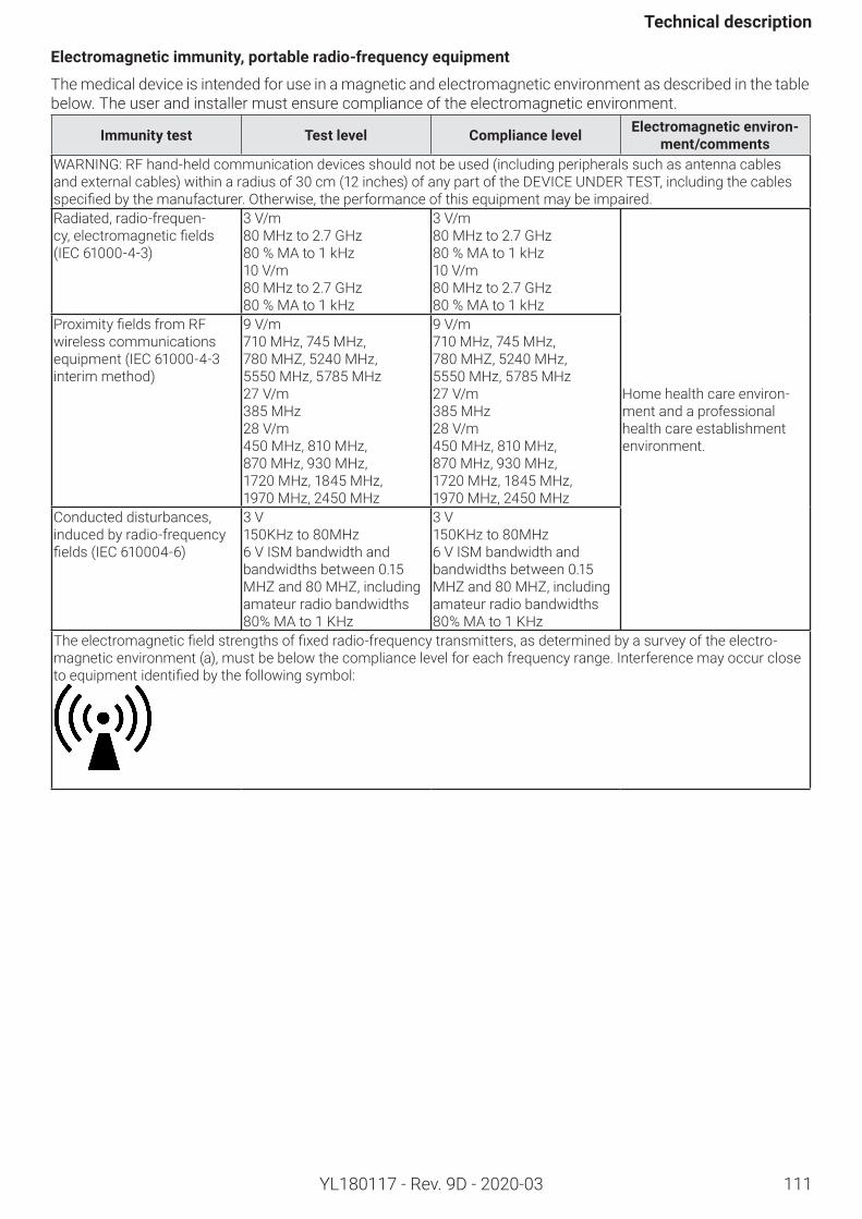
111
Technicaldescription
YL180117 - Rev. 9D - 2020-03
Electromagneticimmunity,portableradio-frequencyequipment
The medical device is intended for use in a magnetic and electromagnetic environment as described in the table below. The user and installer must ensure compliance of the electromagnetic environment.
Immunitytest Testlevel Compliancelevel Electromagneticenviron-ment/comments
WARNING: RF hand-held communication devices should not be used (including peripherals such as antenna cables and external cables) within a radius of 30 cm (12 inches) of any part of the DEVICE UNDER TEST, including the cables specifiedbythemanufacturer.Otherwise,theperformanceofthisequipmentmaybeimpaired.Radiated, radio-frequen-cy,electromagneticfields(IEC 61000-4-3)
3 V/m 80 MHz to 2.7 GHz 80 % MA to 1 kHz10 V/m 80 MHz to 2.7 GHz 80 % MA to 1 kHz
3 V/m 80 MHz to 2.7 GHz 80 % MA to 1 kHz10 V/m 80 MHz to 2.7 GHz 80 % MA to 1 kHz
Home health care environ-ment and a professional health care establishment environment.
ProximityfieldsfromRFwireless communications equipment (IEC 61000-4-3 interim method)
9 V/m 710 MHz, 745 MHz, 780 MHZ, 5240 MHz, 5550 MHz, 5785 MHz27 V/m 385 MHz28 V/m 450 MHz, 810 MHz, 870 MHz, 930 MHz, 1720 MHz, 1845 MHz, 1970 MHz, 2450 MHz
9 V/m 710 MHz, 745 MHz, 780 MHZ, 5240 MHz, 5550 MHz, 5785 MHz27 V/m 385 MHz28 V/m 450 MHz, 810 MHz, 870 MHz, 930 MHz, 1720 MHz, 1845 MHz, 1970 MHz, 2450 MHz
Conducted disturbances, induced by radio-frequency fields(IEC 610004-6)
3 V 150KHz to 80MHz6 V ISM bandwidth and bandwidths between 0.15 MHZ and 80 MHZ, including amateur radio bandwidths 80% MA to 1 KHz
3 V 150KHz to 80MHz6 V ISM bandwidth and bandwidths between 0.15 MHZ and 80 MHZ, including amateur radio bandwidths 80% MA to 1 KHz
Theelectromagneticfieldstrengthsoffixedradio-frequencytransmitters,asdeterminedbyasurveyoftheelectro-magnetic environment (a), must be below the compliance level for each frequency range. Interference may occur close toequipmentidentifiedbythefollowingsymbol:
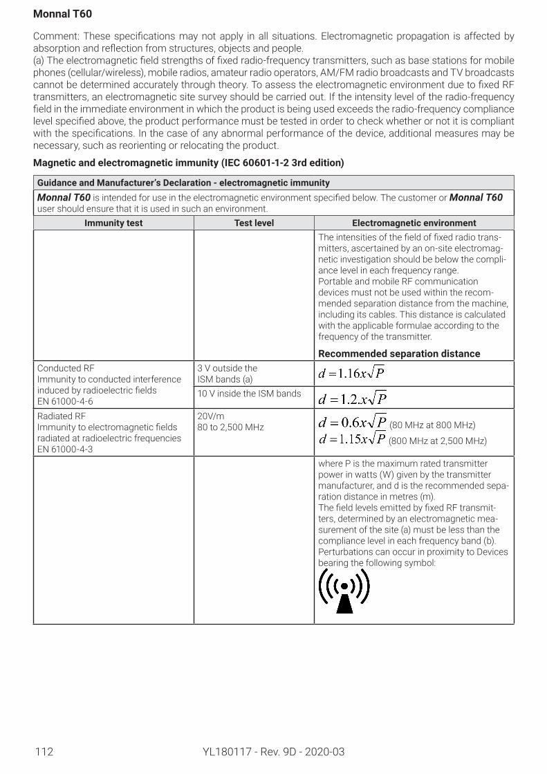
112
Monnal T60
YL180117 - Rev. 9D - 2020-03
Comment:Thesespecificationsmaynotapply inall situations.Electromagneticpropagation isaffectedbyabsorptionandreflectionfromstructures,objectsandpeople.(a)Theelectromagneticfieldstrengthsoffixedradio-frequencytransmitters,suchasbasestationsformobilephones (cellular/wireless), mobile radios, amateur radio operators, AM/FM radio broadcasts and TV broadcasts cannotbedeterminedaccuratelythroughtheory.ToassesstheelectromagneticenvironmentduetofixedRFtransmitters, an electromagnetic site survey should be carried out. If the intensity level of the radio-frequency fieldintheimmediateenvironmentinwhichtheproductisbeingusedexceedstheradio-frequencycompliancelevelspecifiedabove,theproductperformancemustbetestedinordertocheckwhetherornotitiscompliantwiththespecifications.Inthecaseofanyabnormalperformanceofthedevice,additionalmeasuresmaybenecessary, such as reorienting or relocating the product.
Magneticandelectromagneticimmunity(IEC60601-1-23rdedition)
GuidanceandManufacturer’sDeclaration-electromagneticimmunityMonnal T60isintendedforuseintheelectromagneticenvironmentspecifiedbelow.ThecustomerorMonnal T60 user should ensure that it is used in such an environment.
Immunitytest Testlevel ElectromagneticenvironmentTheintensitiesofthefieldoffixedradiotrans-mitters, ascertained by an on-site electromag-netic investigation should be below the compli-ance level in each frequency range.Portable and mobile RF communication devices must not be used within the recom-mended separation distance from the machine, including its cables. This distance is calculated with the applicable formulae according to the frequency of the transmitter.
RecommendedseparationdistanceConducted RFImmunity to conducted interference inducedbyradioelectricfieldsEN 61000-4-6
3 V outside the ISM bands (a)10 V inside the ISM bands
Radiated RFImmunitytoelectromagneticfieldsradiated at radioelectric frequencies EN 61000-4-3
20V/m 80 to 2,500 MHz (80 MHz at 800 MHz)
(800 MHz at 2,500 MHz)
where P is the maximum rated transmitter power in watts (W) given by the transmitter manufacturer, and d is the recommended sepa-ration distance in metres (m). ThefieldlevelsemittedbyfixedRFtransmit-ters, determined by an electromagnetic mea-surement of the site (a) must be less than the compliance level in each frequency band (b). Perturbations can occur in proximity to Devices bearing the following symbol:
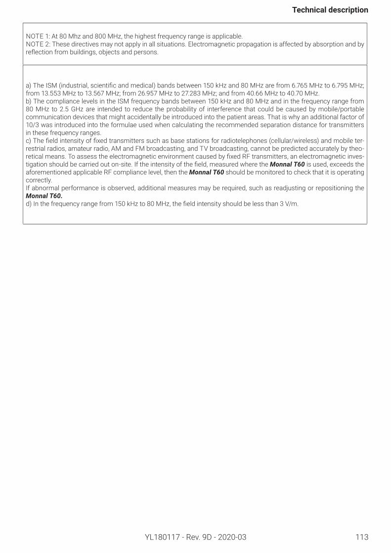
113
Technicaldescription
YL180117 - Rev. 9D - 2020-03
NOTE 1: At 80 Mhz and 800 MHz, the highest frequency range is applicable.NOTE 2: These directives may not apply in all situations. Electromagnetic propagation is affected by absorption and by reflectionfrombuildings,objectsandpersons.
a)TheISM(industrial,scientificandmedical)bandsbetween150kHzand80MHzarefrom6.765MHzto6.795MHz;from 13.553 MHz to 13.567 MHz; from 26.957 MHz to 27.283 MHz; and from 40.66 MHz to 40.70 MHz.b) The compliance levels in the ISM frequency bands between 150 kHz and 80 MHz and in the frequency range from 80 MHz to 2.5 GHz are intended to reduce the probability of interference that could be caused by mobile/portable communication devices that might accidentally be introduced into the patient areas. That is why an additional factor of 10/3 was introduced into the formulae used when calculating the recommended separation distance for transmitters in these frequency ranges.c)Thefieldintensityoffixedtransmitterssuchasbasestationsforradiotelephones(cellular/wireless)andmobileter-restrial radios, amateur radio, AM and FM broadcasting, and TV broadcasting, cannot be predicted accurately by theo-reticalmeans.ToassesstheelectromagneticenvironmentcausedbyfixedRFtransmitters,anelectromagneticinves-tigationshouldbecarriedouton-site.Iftheintensityofthefield,measuredwheretheMonnal T60 is used, exceeds the aforementioned applicable RF compliance level, then the Monnal T60 should be monitored to check that it is operating correctly.If abnormal performance is observed, additional measures may be required, such as readjusting or repositioning the Monnal T60.d)Inthefrequencyrangefrom150kHzto80MHz,thefieldintensityshouldbelessthan3V/m.
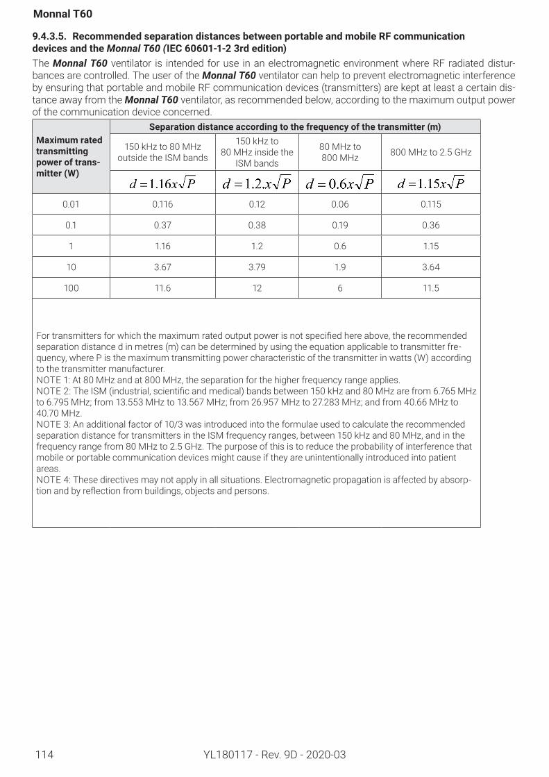
114
Monnal T60
YL180117 - Rev. 9D - 2020-03
9.4.3.5. RecommendedseparationdistancesbetweenportableandmobileRFcommunication devicesandtheMonnal T60 (IEC60601-1-23rdedition)The Monnal T60 ventilator is intended for use in an electromagnetic environment where RF radiated distur-bances are controlled. The user of the Monnal T60 ventilator can help to prevent electromagnetic interference by ensuring that portable and mobile RF communication devices (transmitters) are kept at least a certain dis-tance away from the Monnal T60 ventilator, as recommended below, according to the maximum output power of the communication device concerned.
Maximumratedtransmittingpoweroftrans-mitter(W)
Separationdistanceaccordingtothefrequencyofthetransmitter(m)
150 kHz to 80 MHz outside the ISM bands
150 kHz to 80 MHz inside the
ISM bands
80 MHz to 800 MHz 800 MHz to 2.5 GHz
0.01 0.116 0.12 0.06 0.115
0.1 0.37 0.38 0.19 0.36
1 1.16 1.2 0.6 1.15
10 3.67 3.79 1.9 3.64
100 11.6 12 6 11.5
Fortransmittersforwhichthemaximumratedoutputpowerisnotspecifiedhereabove,therecommendedseparation distance d in metres (m) can be determined by using the equation applicable to transmitter fre-quency, where P is the maximum transmitting power characteristic of the transmitter in watts (W) according to the transmitter manufacturer.NOTE 1: At 80 MHz and at 800 MHz, the separation for the higher frequency range applies.NOTE 2:TheISM(industrial,scientificandmedical)bandsbetween150kHzand80MHzarefrom6.765MHzto 6.795 MHz; from 13.553 MHz to 13.567 MHz; from 26.957 MHz to 27.283 MHz; and from 40.66 MHz to 40.70 MHz.NOTE 3: An additional factor of 10/3 was introduced into the formulae used to calculate the recommended separation distance for transmitters in the ISM frequency ranges, between 150 kHz and 80 MHz, and in the frequency range from 80 MHz to 2.5 GHz. The purpose of this is to reduce the probability of interference that mobile or portable communication devices might cause if they are unintentionally introduced into patient areas.NOTE 4: These directives may not apply in all situations. Electromagnetic propagation is affected by absorp-tionandbyreflectionfrombuildings,objectsandpersons.
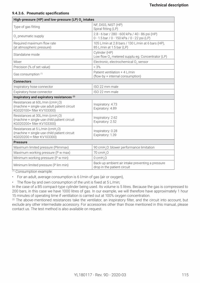
115
Technicaldescription
YL180117 - Rev. 9D - 2020-03
9.4.3.6. Pneumaticspecifications
High-pressure(HP)andlow-pressure(LP)O2intakes
Typeofgasfitting NF, DISS, NIST (HP)Spiralfitting(LP)
O2 pneumatic supply 2.8 - 6 bar / 280 - 600 kPa / 40 - 86 psi (HP)0 - 1.5 bar / 0 - 150 kPa / 0 - 22 psi (LP)
Requiredmaximumflowrate (at atmospheric pressure)
105 L/min at 2.8 bars / 130 L/min at 6 bars (HP),85 L/min at 1.5 bar (LP)
Standalone mode Cylinder (HP)LowflowO2 metered supplu eg. Concentrator (LP)
Mixer Electronic, electrochemical O2 sensor Precision (% of set value) < 3%
Gas consumption (1) Patient ventilation + 4 L/min (flow-by+internalconsumption)
ConnectorsInspiratory hose connector ISO 22 mm maleExpiratory hose connector ISO 22 mm maleInspiratoryandexpiratoryresistances(2)
Resistances at 60L/min (cmH2O) (machine + single-use adult patient circuit KG020100+filterKV103300)
Inspiratory: 4.73Expiratory: 4.89
Resistances at 30L/min (cmH2O) (machine + single-use child patient circuit KG020200+filterKV103300)
Inspiratory: 2.62Expiratory: 2.52
Resistances at 5 L/min (cmH2O) (machine + single-use child patient circuit KG020200+filterKV103300)
Inspiratory: 0.28Expiratory: 1.39
PressureMaximum limited pressure (Plimmax) 90 cmH2O: blower performance limitationMaximum working pressure (P w max) 70 cmH2OMinimum working pressure (P w min) 0 cmH2O
Minimum limited pressure (P lim min) Back-up ambient air intake preventing a pressure drop in the patient circuit
(1) Consumption example:• For an adult, average consumption is 6 l/min of gas (air or oxygen),• Theflow-byandownconsumptionoftheunitisfixedat5L/min;In the case of a B5 compact-type cylinder being used. Its volume is 5 litres. Because the gas is compressed to 200 bars, in this case we have 1000 litres of gas. In our example, we will therefore have approximately 1 hour 15 minutesofoperatingtimeifventilationiscarriedoutat100%oxygenconcentration.(2)Theabove-mentionedresistancestaketheventilator,an inspiratoryfilter,andthecircuit intoaccount,butexclude any other intermediate accessory. For accessories other than those mentioned in this manual, please contact us. The test method is also available on request.
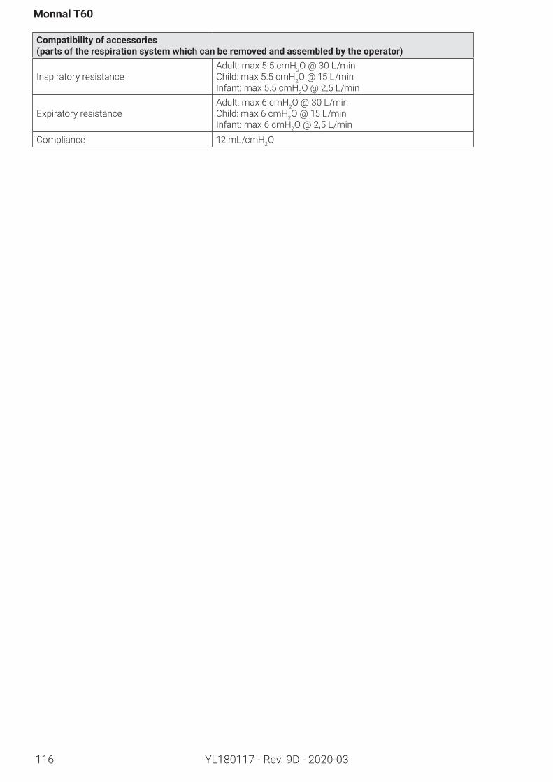
116
Monnal T60
YL180117 - Rev. 9D - 2020-03
Compatibilityofaccessories (partsoftherespirationsystemwhichcanberemovedandassembledbytheoperator)
Inspiratory resistanceAdult: max 5.5 cmH2O @ 30 L/minChild: max 5.5 cmH2O @ 15 L/minInfant: max 5.5 cmH2O @ 2,5 L/min
Expiratory resistanceAdult: max 6 cmH2O @ 30 L/minChild: max 6 cmH2O @ 15 L/minInfant: max 6 cmH2O @ 2,5 L/min
Compliance 12 mL/cmH2O
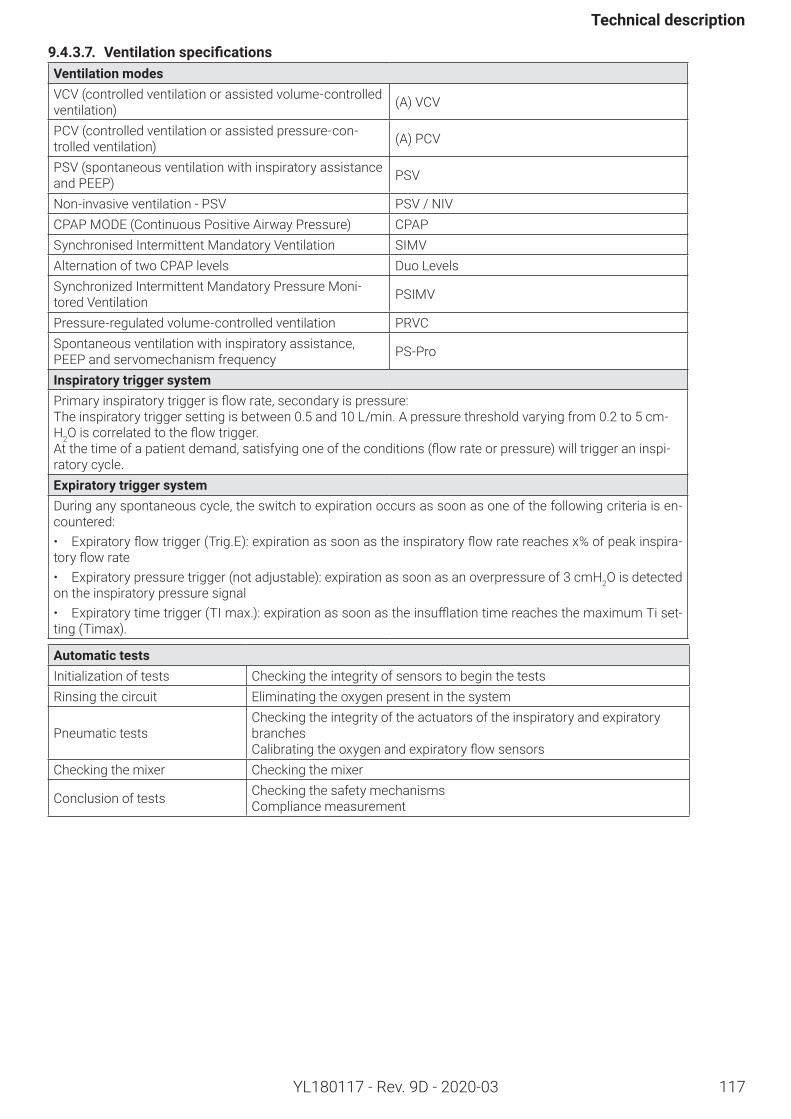
117
Technicaldescription
YL180117 - Rev. 9D - 2020-03
9.4.3.7. VentilationspecificationsVentilationmodesVCV (controlled ventilation or assisted volume-controlled ventilation) (A) VCV
PCV (controlled ventilation or assisted pressure-con-trolled ventilation) (A) PCV
PSV (spontaneous ventilation with inspiratory assistance and PEEP) PSV
Non-invasive ventilation - PSV PSV / NIVCPAP MODE (Continuous Positive Airway Pressure) CPAPSynchronised Intermittent Mandatory Ventilation SIMVAlternation of two CPAP levels Duo LevelsSynchronized Intermittent Mandatory Pressure Moni-tored Ventilation PSIMV
Pressure-regulated volume-controlled ventilation PRVCSpontaneous ventilation with inspiratory assistance, PEEP and servomechanism frequency PS-Pro
InspiratorytriggersystemPrimaryinspiratorytriggerisflowrate,secondaryispressure:The inspiratory trigger setting is between 0.5 and 10 L/min. A pressure threshold varying from 0.2 to 5 cm-H2Oiscorrelatedtotheflowtrigger.Atthetimeofapatientdemand,satisfyingoneoftheconditions(flowrateorpressure)willtriggeraninspi-ratory cycle. ExpiratorytriggersystemDuring any spontaneous cycle, the switch to expiration occurs as soon as one of the following criteria is en-countered: • Expiratoryflowtrigger(Trig.E):expirationassoonastheinspiratoryflowratereachesx%ofpeakinspira-toryflowrate• Expiratory pressure trigger (not adjustable): expiration as soon as an overpressure of 3 cmH2O is detected on the inspiratory pressure signal• Expiratorytimetrigger(TImax.):expirationassoonastheinsufflationtimereachesthemaximumTiset-ting (Timax).
AutomatictestsInitialization of tests Checking the integrity of sensors to begin the testsRinsing the circuit Eliminating the oxygen present in the system
Pneumatic testsChecking the integrity of the actuators of the inspiratory and expiratory branchesCalibratingtheoxygenandexpiratoryflowsensors
Checking the mixer Checking the mixer
Conclusion of tests Checking the safety mechanismsCompliance measurement
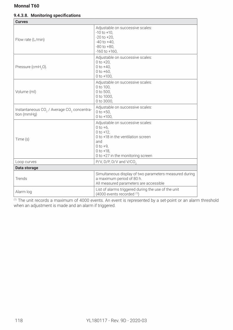
118
Monnal T60
YL180117 - Rev. 9D - 2020-03
9.4.3.8. MonitoringspecificationsCurves
Flow rate (L/min)
Adjustable on successive scales: -10 to +10, -20 to +20, -40 to +40, -80 to +80, -160 to +160,
Pressure (cmH2O).
Adjustable on successive scales: 0 to +20, 0 to +40, 0 to +60, 0 to +100,
Volume (ml)
Adjustable on successive scales: 0 to 100, 0 to 500, 0 to 1000, 0 to 3000,
Instantaneous CO2 / Average CO2 concentra-tion (mmHg)
Adjustable on successive scales: 0 to +50, 0 to +100,
Time (s)
Adjustable on successive scales: 0 to +6, 0 to +12, 0 to +18 in the ventilation screenand0 to +9,0 to +18,0 to +27 in the monitoring screen
Loop curves P/V, D/P, D/V and V/CO2
Datastorage
TrendsSimultaneous display of two parameters measured during a maximum period of 80 h. All measured parameters are accessible
Alarm log List of alarms triggered during the use of the unit (4000 events recorded (1))
(1) The unit records a maximum of 4000 events. An event is represented by a set-point or an alarm threshold when an adjustment is made and an alarm if triggered.
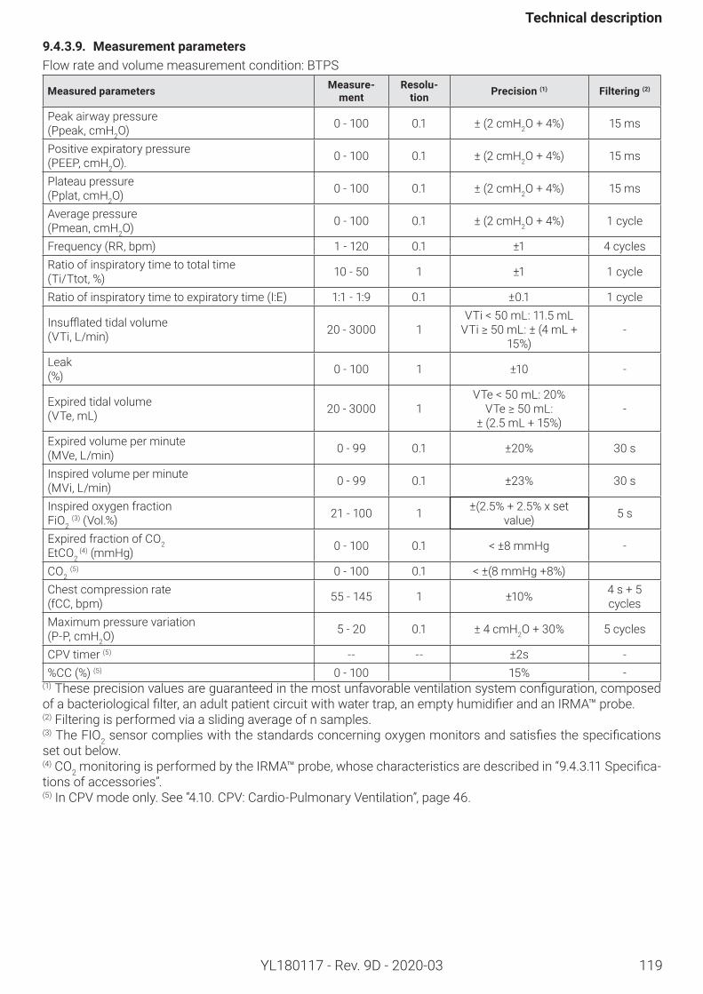
119
Technicaldescription
YL180117 - Rev. 9D - 2020-03
9.4.3.9. MeasurementparametersFlow rate and volume measurement condition: BTPS
Measuredparameters Measure-ment
Resolu-tion Precision(1) Filtering(2)
Peak airway pressure (Ppeak, cmH2O) 0 - 100 0.1 ± (2 cmH2O + 4%) 15 ms
Positive expiratory pressure (PEEP, cmH2O). 0 - 100 0.1 ± (2 cmH2O + 4%) 15 ms
Plateau pressure (Pplat, cmH2O) 0 - 100 0.1 ± (2 cmH2O + 4%) 15 ms
Average pressure (Pmean, cmH2O) 0 - 100 0.1 ± (2 cmH2O + 4%) 1 cycle
Frequency (RR, bpm) 1 - 120 0.1 ±1 4 cyclesRatio of inspiratory time to total time (Ti/Ttot, %) 10 - 50 1 ±1 1 cycle
Ratio of inspiratory time to expiratory time (I:E) 1:1 -1:9 0.1 ±0.1 1 cycle
Insufflatedtidalvolume (VTi, L/min) 20 - 3000 1
VTi < 50 mL: 11.5 mLVTi≥50mL:±(4mL+
15%)-
Leak (%) 0 - 100 1 ±10 -
Expired tidal volume (VTe, mL) 20 - 3000 1
VTe < 50 mL: 20%VTe≥50mL:
± (2.5 mL + 15%)-
Expired volume per minute (MVe, L/min) 0 - 99 0.1 ±20% 30 s
Inspired volume per minute (MVi, L/min) 0 - 99 0.1 ±23% 30 s
Inspired oxygen fraction FiO2
(3) (Vol.%) 21 - 100 1 ±(2.5% + 2.5% x set value) 5 s
Expired fraction of CO2 EtCO2
(4) (mmHg) 0 - 100 0.1 < ±8 mmHg -
CO2 (5) 0 - 100 0.1 < ±(8 mmHg +8%)
Chest compression rate (fCC, bpm) 55 - 145 1 ±10% 4 s + 5
cyclesMaximum pressure variation (P-P, cmH2O) 5 - 20 0.1 ± 4 cmH2O + 30% 5 cycles
CPV timer (5) -- -- ±2s -%CC (%) (5) 0 - 100 15% -
(1)Theseprecisionvaluesareguaranteedinthemostunfavorableventilationsystemconfiguration,composedofabacteriologicalfilter,anadultpatientcircuitwithwatertrap,anemptyhumidifierandanIRMA™probe.(2) Filtering is performed via a sliding average of n samples.(3) The FIO2sensorcomplieswiththestandardsconcerningoxygenmonitorsandsatisfiesthespecificationsset out below.(4) CO2 monitoring is performed by the IRMA™ probe, whose characteristics are described in “9.4.3.11Specifica-tions of accessories”.(5) In CPV mode only. See “4.10. CPV: Cardio-Pulmonary Ventilation”, page 46.
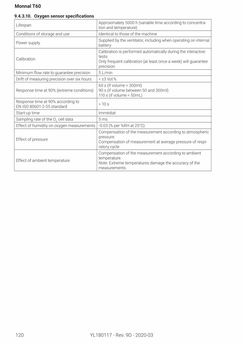
120
Monnal T60
YL180117 - Rev. 9D - 2020-03
9.4.3.10. Oxygensensorspecifications
Lifespan Approximately 5000 h (variable time according to concentra-tion and temperature)
Conditions of storage and use Identical to those of the machine
Power supply Supplied by the ventilator, including when operating on internal battery
Calibration
Calibration is performed automatically during the interactive tests.Only frequent calibration (at least once a week) will guarantee precision.
Minimumflowratetoguaranteeprecision 5 L/minDrift of measuring precision over six hours < ±3 Vol.%
Response time at 90% (extreme conditions)60 s (if volume > 300ml)90 s (if volume between 50 and 300ml)110 s (if volume < 50mL)
Response time at 90% according to EN ISO 80601-2-55standard > 10 s
Start-up time ImmédiatSampling rate of the O2 cell data 5 msEffect of humidity on oxygen measurements -0.03 (% per %RH at 25°C)
Effect of pressure
Compensation of the measurement according to atmospheric pressure.Compensation of measurement at average pressure of respi-ratory cycle
Effect of ambient temperature
Compensation of the measurement according to ambient temperature.Note: Extreme temperatures damage the accuracy of the measurements.
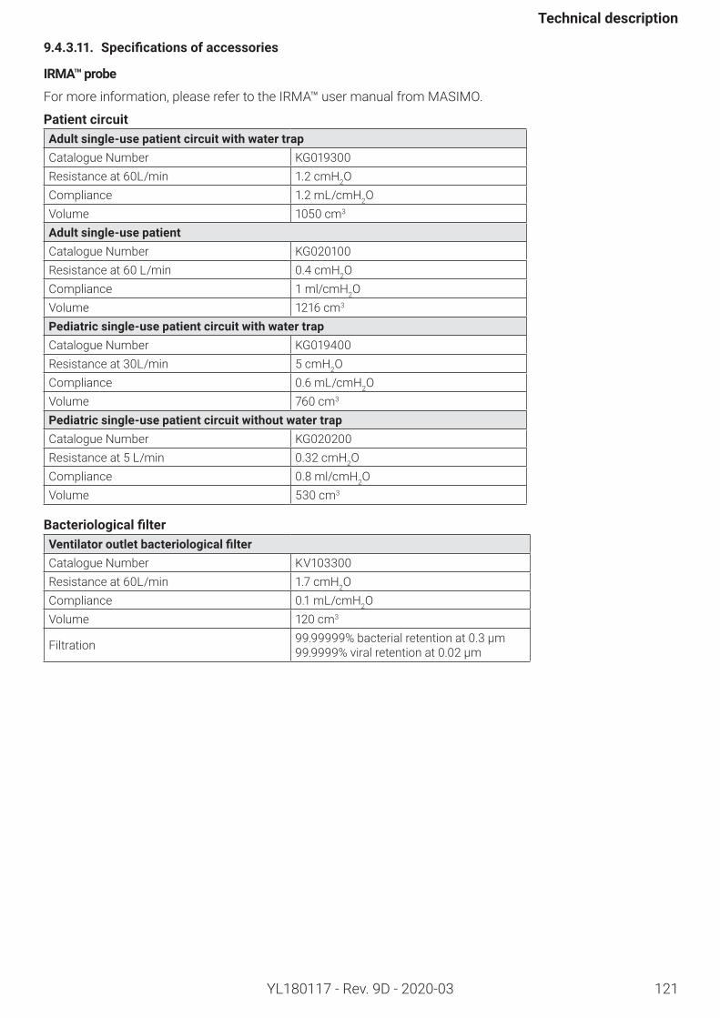
121
Technicaldescription
YL180117 - Rev. 9D - 2020-03
9.4.3.11. Specificationsofaccessories
IRMA™probe
For more information, please refer to the IRMA™ user manual from MASIMO.
PatientcircuitAdultsingle-usepatientcircuitwithwatertrapCatalogue Number KG019300Resistance at 60L/min 1.2 cmH2OCompliance 1.2 mL/cmH2OVolume 1050 cm3
Adultsingle-usepatientCatalogue Number KG020100Resistance at 60 L/min 0.4 cmH2OCompliance 1 ml/cmH2OVolume 1216 cm3
Pediatricsingle-usepatientcircuitwithwatertrapCatalogue Number KG019400Resistance at 30L/min 5 cmH2OCompliance 0.6 mL/cmH2OVolume 760 cm3
Pediatricsingle-usepatientcircuitwithoutwatertrapCatalogue Number KG020200Resistance at 5 L/min 0.32 cmH2OCompliance 0.8 ml/cmH2OVolume 530 cm3
BacteriologicalfilterVentilatoroutletbacteriologicalfilterCatalogue Number KV103300Resistance at 60L/min 1.7 cmH2OCompliance 0.1 mL/cmH2OVolume 120 cm3
Filtration 99.99999% bacterial retention at 0.3 µm99.9999% viral retention at 0.02 µm
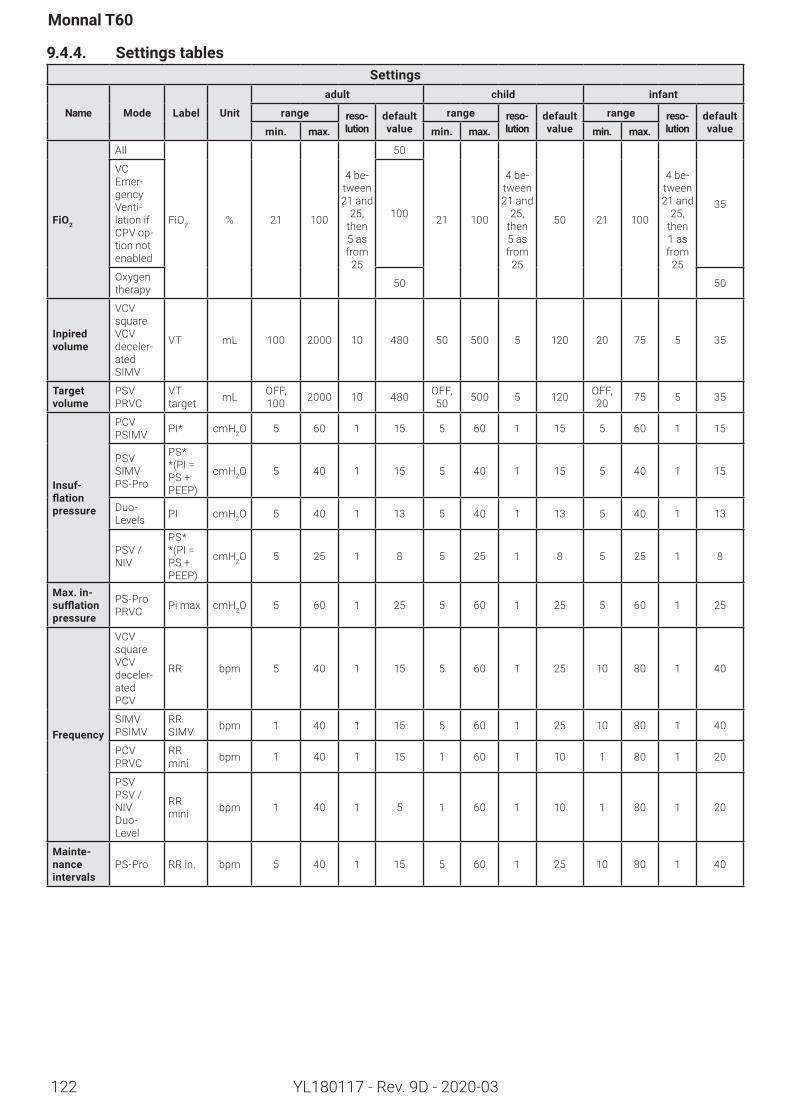
122
Monnal T60
YL180117 - Rev. 9D - 2020-03
9.4.4. SettingstablesSettings
Name Mode Label Unit
adult child infant
range reso-lution
default value
range reso-lution
default value
range reso-lution
default valuemin. max. min. max. min. max.
FiO2
All
FiO2 % 21 100
4 be-tween 21 and
25, then 5 as from
25
50
21 100
4 be-tween 21 and
25, then 5 as from
25
50 21 100
4 be-tween 21 and
25, then 1 as from
25
35
VC Emer-gency Venti-lation if CPV op-tion not enabled
100
Oxygen therapy 50 50
Inpiredvolume
VCV squareVCV deceler-atedSIMV
VT mL 100 2000 10 480 50 500 5 120 20 75 5 35
Targetvolume
PSVPRVC
VT target mL OFF,
100 2000 10 480 OFF, 50 500 5 120 OFF,
20 75 5 35
Insuf-flationpressure
PCVPSIMV PI* cmH2O 5 60 1 15 5 60 1 15 5 60 1 15
PSVSIMVPS-Pro
PS* *(PI=PS + PEEP)
cmH2O 5 40 1 15 5 40 1 15 5 40 1 15
Duo- Levels PI cmH2O 5 40 1 13 5 40 1 13 5 40 1 13
PSV / NIV
PS* *(PI=PS + PEEP)
cmH2O 5 25 1 8 5 25 1 8 5 25 1 8
Max.in-sufflationpressure
PS-ProPRVC Pi max cmH2O 5 60 1 25 5 60 1 25 5 60 1 25
Frequency
VCV squareVCV deceler-atedPCV
RR bpm 5 40 1 15 5 60 1 25 10 80 1 40
SIMVPSIMV
RR SIMV bpm 1 40 1 15 5 60 1 25 10 80 1 40
PCVPRVC
RR mini bpm 1 40 1 15 1 60 1 10 1 80 1 20
PSV PSV / NIVDuo- Level
RR mini bpm 1 40 1 5 1 60 1 10 1 80 1 20
Mainte-nanceintervals
PS-Pro RR in. bpm 5 40 1 15 5 60 1 25 10 80 1 40
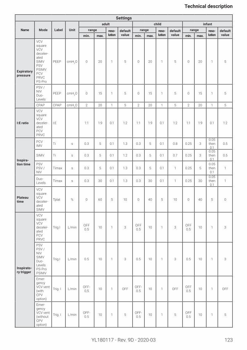
123
Technicaldescription
YL180117 - Rev. 9D - 2020-03
Settings
Name Mode Label Unit
adult child infant
range reso-lution
default value
range reso-lution
default value
range reso-lution
default valuemin. max. min. max. min. max.
Expiratorypressure
VCV squareVCV deceler-atedSIMVPSVPSIMVPCVPRVCPS-Pro
PEEP cmH2O 0 20 1 5 0 20 1 5 0 20 1 5
PSV / NIVDuo- Levels
PEEP cmH2O 0 15 1 5 0 15 1 5 0 15 1 5
CPAP CPAP cmH2O 2 20 1 5 2 20 1 5 2 20 1 5
I:Eratio
VCV squareVCV deceler-atedPCVPRVC
I:E 1:1 1:9 0.1 1:2 1:1 1:9 0.1 1:2 1:1 1:9 0.1 1:2
Inspira-tiontime
PCV IMV Ti s 0.3 5 0.1 1.3 0.3 5 0.1 0.8 0.25 3
0.05 then 0.1
0.5
SIMV Ti s 0.3 5 0.1 1.2 0.3 5 0.1 0.7 0.25 30.05 then 0.1
0.5
PSV PSV / NIV
Timax s 0.3 5 0.1 1.3 0.3 5 0.1 1 0.25 50.05 then 0.1
1
Duo- Levels Timax s 0.3 30 0.1 1.3 0.3 30 0.1 1 0.25 30
0.05 then 0.1
1
Plateautime
VCV squareVCV deceler-atedSIMV
Tplat % 0 60 5 10 0 40 5 10 0 40 5 0
Inspirato-rytrigger
VCV squareVCV deceler-atedPCVPRVC
Trig.I L/min OFF 0.5 10 1 3 OFF
0.5 10 1 3 OFF 0.5 10 1 3
PSVPSV / NIVSIMVDuo- LevelsPS-ProPSIMV
Trig.I L/min 0.5 10 1 3 0.5 10 1 3 0.5 10 1 3
Emer-gency VCV vent (with CPV option)
Trig. I L/min OFF- 0,5 10 1 OFF OFF-
0.5 10 1 OFF OFF 0.5 10 1 OFF
Emer-gency VCV vent (without CPV option)
Trig. I L/min OFF- 0.5 10 1 5 OFF-
0.5 10 1 5 OFF 0.5 10 1 5
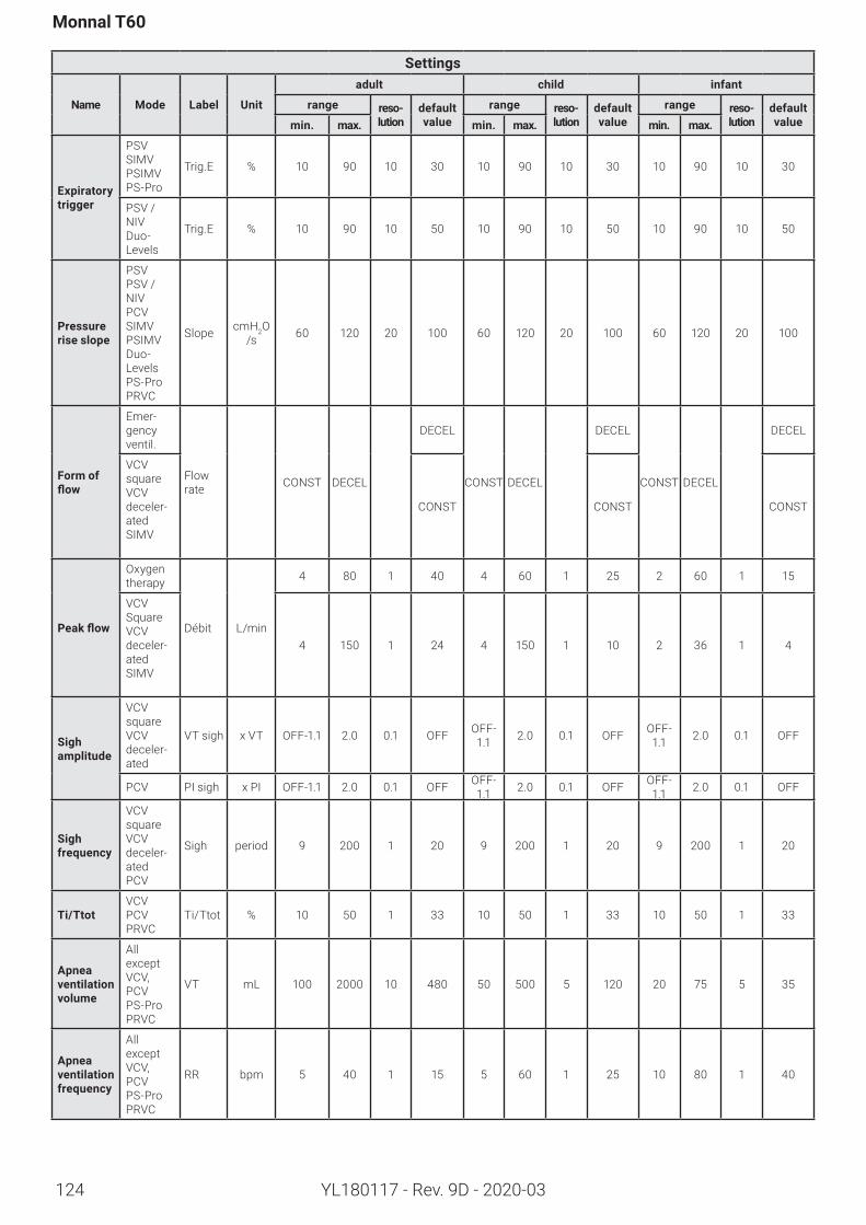
124
Monnal T60
YL180117 - Rev. 9D - 2020-03
Settings
Name Mode Label Unit
adult child infant
range reso-lution
default value
range reso-lution
default value
range reso-lution
default valuemin. max. min. max. min. max.
Expiratorytrigger
PSVSIMVPSIMVPS-Pro
Trig.E % 10 90 10 30 10 90 10 30 10 90 10 30
PSV / NIVDuo- Levels
Trig.E % 10 90 10 50 10 90 10 50 10 90 10 50
Pressureriseslope
PSVPSV / NIVPCVSIMVPSIMVDuo- LevelsPS-ProPRVC
Slope cmH2O /s 60 120 20 100 60 120 20 100 60 120 20 100
Form of flow
Emer-gency ventil.
Flow rate CONST DECEL
DECEL
CONST DECEL
DECEL
CONST DECEL
DECEL
VCV squareVCV deceler-atedSIMV
CONST CONST CONST
Peakflow
Oxygen therapy
Débit L/min
4 80 1 40 4 60 1 25 2 60 1 15
VCV SquareVCV deceler-atedSIMV
4 150 1 24 4 150 1 10 2 36 1 4
Sigh amplitude
VCV squareVCV deceler-ated
VT sigh x VT OFF-1.1 2.0 0.1 OFF OFF-1.1 2.0 0.1 OFF OFF-
1.1 2.0 0.1 OFF
PCV PI sigh x PI OFF-1.1 2.0 0.1 OFF OFF-1.1 2.0 0.1 OFF OFF-
1.1 2.0 0.1 OFF
Sigh frequency
VCV squareVCV deceler-atedPCV
Sigh period 9 200 1 20 9 200 1 20 9 200 1 20
Ti/TtotVCVPCVPRVC
Ti/Ttot % 10 50 1 33 10 50 1 33 10 50 1 33
Apneaventilationvolume
All except VCV,PCVPS-ProPRVC
VT mL 100 2000 10 480 50 500 5 120 20 75 5 35
Apneaventilationfrequency
All except VCV,PCVPS-ProPRVC
RR bpm 5 40 1 15 5 60 1 25 10 80 1 40
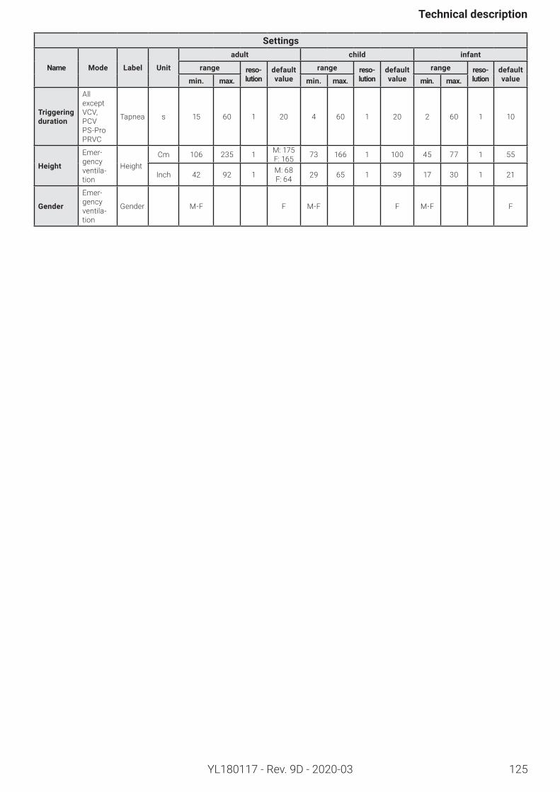
125
Technicaldescription
YL180117 - Rev. 9D - 2020-03
Settings
Name Mode Label Unit
adult child infant
range reso-lution
default value
range reso-lution
default value
range reso-lution
default valuemin. max. min. max. min. max.
Triggeringduration
All except VCV,PCVPS-ProPRVC
Tapnea s 15 60 1 20 4 60 1 20 2 60 1 10
Height
Emer-gency ventila-tion
HeightCm 106 235 1 M: 175
F: 165 73 166 1 100 45 77 1 55
Inch 42 92 1 M: 68F: 64 29 65 1 39 17 30 1 21
Gender
Emer-gency ventila-tion
Gender M-F F M-F F M-F F
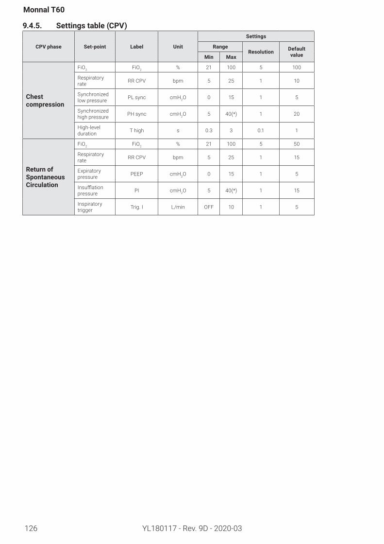
126
Monnal T60
YL180117 - Rev. 9D - 2020-03
9.4.5. Settingstable(CPV)
CPVphase Set-point Label Unit
Settings
RangeResolution Default
valueMin Max
Chest compression
FiO2 FiO2 % 21 100 5 100
Respiratory rate RR CPV bpm 5 25 1 10
Synchronized low pressure PL sync cmH2O 0 15 1 5
Synchronized high pressure PH sync cmH2O 5 40(*) 1 20
High-level duration T high s 0.3 3 0.1 1
Return of SpontaneousCirculation
FiO2 FiO2 % 21 100 5 50
Respiratory rate RR CPV bpm 5 25 1 15
Expiratory pressure PEEP cmH2O 0 15 1 5
Insufflationpressure PI cmH2O 5 40(*) 1 15
Inspiratory trigger Trig. I L/min OFF 10 1 5
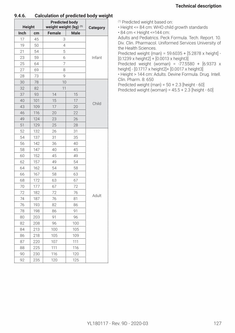
127
Technicaldescription
YL180117 - Rev. 9D - 2020-03
9.4.6. Calculationofpredictedbodyweight
HeightPredictedbody
weightweight(kg)(1) CategoryInch cm Female Male17 45 3
Infant
19 50 421 54 523 59 625 64 727 69 828 73 930 78 10
Child
32 82 1137 93 14 1540 101 15 1743 109 17 2046 116 20 2249 124 23 2651 129 25 2852 132 26 31
Adult
54 137 31 3556 142 36 4058 147 40 4560 152 45 4962 157 49 5464 162 54 5866 167 58 6368 172 63 6770 177 67 7272 182 72 7674 187 76 8176 193 82 8678 198 86 9180 203 91 9682 208 96 10084 213 100 10586 218 105 10987 220 107 11188 225 111 11690 230 116 12092 235 120 125
(1) Predicted weight based on:•Height<=84cm:WHOchildgrowthstandards•84cm<Height<=144cm:Adults and Pediatrics. Peck Formula. Tech. Report. 10. Div. Clin. Pharmacol. Uniformed Services University of the Health Sciences.Predictedweight(man)=59.6035+[5.2878xheight]-[0.1239xheight2]+[0.0013xheight3]Predicted weight (woman) = -77.5580 + [6.9373 xheight]-[0.1717xheight2]+[0.0017xheight3]• Height > 144 cm: Adults. Devine Formula. Drug. Intell. Clin. Pharm. 8: 650Predictedweight(man)=50+2.3[height-60]Predictedweight(woman)=45.5+2.3[height-60]
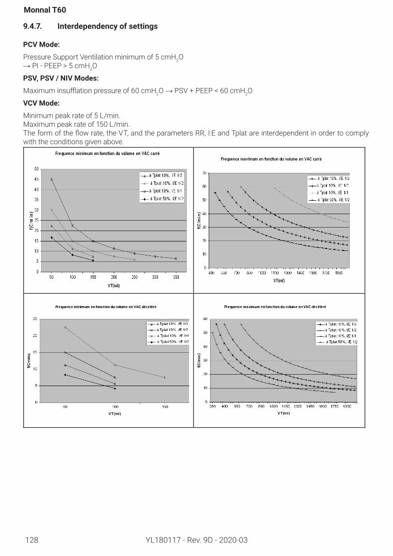
128
Monnal T60
YL180117 - Rev. 9D - 2020-03
9.4.7. Interdependencyofsettings
PCVMode:
Pressure Support Ventilation minimum of 5 cmH2O→PI -PEEP>5cmH2O
PSV,PSV/NIVModes:
Maximuminsufflationpressureof60cmH2O → PSV + PEEP < 60 cmH2O
VCVMode:
Minimum peak rate of 5 L/min.Maximum peak rate of 150 L/min.Theformoftheflowrate,theVT,andtheparametersRR,I:EandTplatareinterdependentinordertocomplywith the conditions given above.
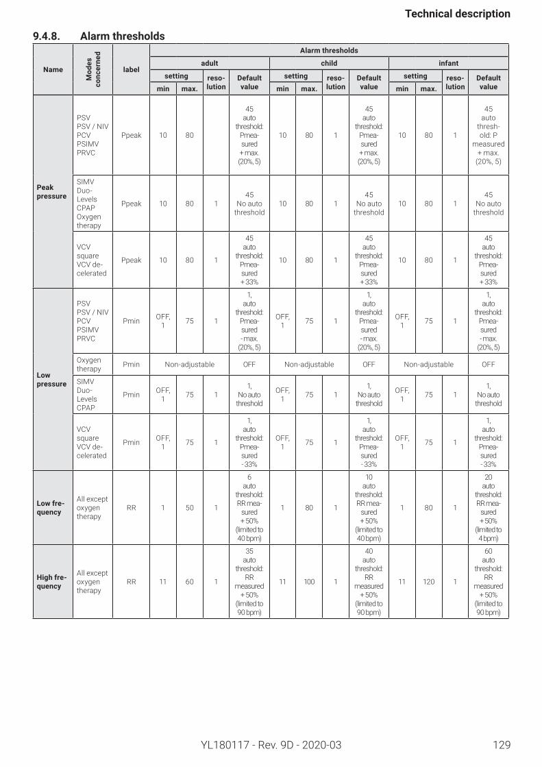
129
Technicaldescription
YL180117 - Rev. 9D - 2020-03
9.4.8. Alarmthresholds
Name
Mod
es
conc
erne
d
label
Alarmthresholds
adult child infant
setting reso-lution
Default value
setting reso-lution
Default value
setting reso-lution
Default valuemin max. min max. min max.
Peakpressure
PSVPSV / NIVPCVPSIMVPRVC
Ppeak 10 80
45 auto
threshold: Pmea-sured + max. (20%, 5)
10 80 1
45 auto
threshold: Pmea-sured + max. (20%, 5)
10 80 1
45auto
thresh-old: P
measured + max.
(20%, 5)
SIMVDuo- LevelsCPAPOxygen therapy
Ppeak 10 80 145
No auto threshold
10 80 145
No auto threshold
10 80 145
No auto threshold
VCV squareVCV de-celerated
Ppeak 10 80 1
45 auto
threshold: Pmea-sured + 33%
10 80 1
45 auto
threshold: Pmea-sured + 33%
10 80 1
45 auto
threshold: Pmea-sured + 33%
Lowpressure
PSVPSV / NIVPCVPSIMVPRVC
Pmin OFF, 1 75 1
1, auto
threshold: Pmea-sured- max.
(20%, 5)
OFF, 1 75 1
1, auto
threshold: Pmea-sured- max.
(20%, 5)
OFF, 1 75 1
1, auto
threshold: Pmea-sured- max.
(20%, 5)
Oxygen therapy Pmin Non-adjustable OFF Non-adjustable OFF Non-adjustable OFF
SIMVDuo- LevelsCPAP
Pmin OFF, 1 75 1
1, No auto
threshold
OFF, 1 75 1
1, No auto
threshold
OFF, 1 75 1
1, No auto
threshold
VCV squareVCV de-celerated
Pmin OFF, 1 75 1
1, auto
threshold: Pmea-sured- 33%
OFF, 1 75 1
1, auto
threshold: Pmea-sured- 33%
OFF, 1 75 1
1, auto
threshold: Pmea-sured- 33%
Lowfre-quency
All except oxygen therapy
RR 1 50 1
6 auto
threshold: RR mea-
sured + 50%
(limited to 40 bpm)
1 80 1
10 auto
threshold: RR mea-
sured + 50%
(limited to 40 bpm)
1 80 1
20 auto
threshold: RR mea-
sured + 50%
(limited to 4 bpm)
Highfre-quency
All except oxygen therapy
RR 11 60 1
35 auto
threshold: RR
measured + 50%
(limited to 90 bpm)
11 100 1
40 auto
threshold: RR
measured + 50%
(limited to 90 bpm)
11 120 1
60 auto
threshold: RR
measured + 50%
(limited to 90 bpm)
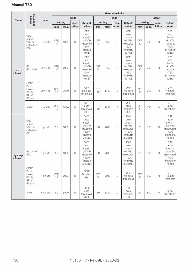
130
Monnal T60
YL180117 - Rev. 9D - 2020-03
Name
Mod
es
conc
erne
d
label
Alarmthresholds
adult child infant
setting reso-lution
Default value
setting reso-lution
Default value
setting reso-lution
Default valuemin max. min max. min max.
Lowexp.volume
VCV squareVCV de-celeratedPCV
Low VTe OFF, 10 2000 10
OFF auto
thresh-old: VTe
measured - 50%
(limited to 10 mL)
OFF, 10 1950 10
OFF auto
thresh-old: VTe
measured - 50%
(limited to 10 mL)
OFF, 10 790 10
OFF auto
thresh-old: VTe
measured - 50%
(limited to 10 mL)
PSVPSV / NIV Low VTe OFF,
10 2000 10
OFF auto
thresh-old: VTe
measured - 75%
(limited to 10 mL)
OFF, 10 1950 10
OFF auto
thresh-old: VTe
measured - 75%
(limited to 10 mL)
OFF, 10 790 10
OFF auto
thresh-old: VTe
measured - 75%
(limited to 10 mL)
CPAPDuo- LevelsPS-ProPRVCPSIMV
Low VTe OFF, 10 2000 10
OFF No auto
threshold
OFF, 10 1950 10
OFF No auto
threshold
OFF, 10 790 10
OFF No auto
threshold
SIMV Low VTe OFF, 10 2000 10
OFF auto
threshold: OFF
OFF, 10 1950 10
OFF auto
threshold: OFF
OFF, 10 790 10
OFF auto
threshold: OFF
Highexp.volume
VCV squareVCV de-celeratedPCV
High Vte 50 3000 10
2000 auto
thresh-old: VTe
measured + 100%
(limited to 3000 mL)
50 2000 10
1000 auto
thresh-old: VTe
measured + 100%
(limited to 3000 mL)
20 800 10
OFF auto
thresh-old: VTe
measured - 50%
(limited to 10 mL)
PSV / NIVPSV High Vte 50 3000 10
2000 auto
thresh-old: VTe
measured + 100%
(limited to 3000 mL)
50 2000 10
1000 auto
thresh-old: VTe
measured + 100%
(limited to 3000 mL)
20 800 10
OFF auto
thresh-old: VTe
measured - 50%
(limited to 10 mL)
CPAPDuo- LevelsPS-ProPRVCPSIMV
High Vte OFF, 10 2000 10
CPAPDuo-Lev-
elsOFF, 10 2000 10
OFF No auto
threshold
OFF, 10 800 10
OFF No auto
threshold
SIMV High Vte 50 3000 10
2000 auto
threshold: 2000
50 2000 10
1000 auto
threshold: 1000
20 800 10
OFF auto
threshold: OFF
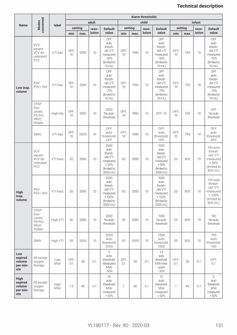
131
Technicaldescription
YL180117 - Rev. 9D - 2020-03
Name
Mod
es
conc
erne
d
label
Alarmthresholds
adult child infant
setting reso-lution
Default value
setting reso-lution
Default value
setting reso-lution
Default valuemin max. min max. min max.
Lowinsp.volume
VCV squareVCV de-celeratedPCV
VTi bas OFF, 10 2000 10
OFF auto
thresh-old: VTi
measured - 50%
(limited to 10 mL)
OFF, 10 1950 10
OFF auto
thresh-old: VTi
measured - 50%
(limited to 10 mL)
OFF, 10 790 10
OFF auto
thresh-old: VTi
measured - 50%
(limited to 10 mL)
PSVPSV / NIV VTi bas OFF,
10 2000 10
OFF auto
thresh-old: VTi
measured - 75%
(limited to 10 mL)
OFF, 10 1950 10
OFF auto
thresh-old: VTi
measured - 75%
(limited to 10 mL)
OFF, 10 790 10
OFF auto
thresh-old: VTi
measured - 75%
(limited to 10 mL)
CPAPDuo- LevelsPS-ProPRVCPSIMV
High Vte OFF, 10 2000 10
2000 No auto
threshold
OFF, 10 1950 10 OFF, 10 OFF,
10 790 10OFF
No auto threshold
SIMV VTi bas OFF, 10 2000 10
OFF auto
threshold: OFF
OFF, 10 1950 10
OFFauto
threshold: OFF
OFF, 10 790 10
OFF auto
threshold: OFF
Highinsp.volume
VCV squareVCV de-celeratedPCV
VTi haut 50 3000 10
2000 auto
thresh-old: VTi
measured + 50%
(limited to 3000 mL)
50 2000 10
1000 auto
thresh-old: VTi
measured + 50%
(limited to 2000 mL)
20 800 10
100 auto thresh-old: VTi
measured + 50%
(limited to 800 mL)
PSVPSV / NIV VTi haut 50 3000 10
2000 auto
thresh-old: VTi
measured + 100%
(limited to 3000 mL)
50 2000 10
1000 auto
thresh-old: VTi
measured + 100%
(limited to 2000 mL)
20 800 10
100 auto thresh-old: VTi
measured + 100%
(limited to 800 mL)
CPAPDuo- LevelsPS-ProPRVCPSIMV
High VTi 50 3000 102000
No auto threshold
50 2000 101000
No auto threshold
20 800 10100
No auto threshold
SIMV High VTi 50 3000 10
2000 auto
threshold: 2000
50 2000 10
1000 auto
threshold: 1000
20 800 10
100 auto
threshold: 100
Lowexpiredvolumepermin-ute
All except oxygen therapy
Low MVe
OFF, 0.1 39 0.1
3 auto
threshold: Measured
MVe - 50%
OFF, 0.1 39 0.1
1.5 auto
threshold: MVe mea-
sured - 50%
OFF, 0.1 39 0.1 OFF,
0.1
Highexpiredvolumepermin-ute
All except oxygen therapy
High MVe 1.5 40 0.1
25 auto
threshold: MVe
measured + 50%
1 40 0.1
10 auto
threshold: MVe
measured + 50%
1 40 0.1
5 auto
threshold: MVe
measured + 50%
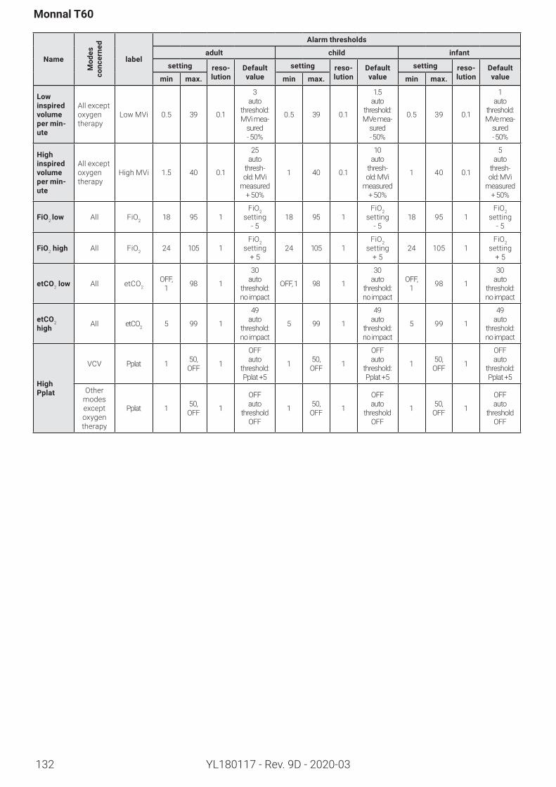
132
Monnal T60
YL180117 - Rev. 9D - 2020-03
Name
Mod
es
conc
erne
d
label
Alarmthresholds
adult child infant
setting reso-lution
Default value
setting reso-lution
Default value
setting reso-lution
Default valuemin max. min max. min max.
Lowinspiredvolumepermin-ute
All except oxygen therapy
Low MVi 0.5 39 0.1
3 auto
threshold: MVi mea-
sured - 50%
0.5 39 0.1
1.5 auto
threshold: MVe mea-
sured - 50%
0.5 39 0.1
1 auto
threshold: MVe mea-
sured - 50%
Highinspiredvolumepermin-ute
All except oxygen therapy
High MVi 1.5 40 0.1
25 auto
thresh-old: MVi
measured + 50%
1 40 0.1
10 auto
thresh-old: MVi
measured + 50%
1 40 0.1
5 auto
thresh-old: MVi
measured + 50%
FiO2 low All FiO2 18 95 1FiO2
setting - 5
18 95 1FiO2
setting - 5
18 95 1FiO2
setting - 5
FiO2high All FiO2 24 105 1FiO2
setting + 5
24 105 1FiO2
setting + 5
24 105 1FiO2
setting + 5
etCO2low All etCO2OFF,
1 98 1
30 auto
threshold: no impact
OFF, 1 98 1
30 auto
threshold: no impact
OFF, 1 98 1
30 auto
threshold: no impact
etCO2 high All etCO2 5 99 1
49 auto
threshold: no impact
5 99 1
49 auto
threshold: no impact
5 99 1
49 auto
threshold: no impact
High Pplat
VCV Pplat 1 50, OFF 1
OFF auto
threshold: Pplat +5
1 50, OFF 1
OFF auto
threshold: Pplat +5
1 50, OFF 1
OFF auto
threshold: Pplat +5
Other modes except oxygen therapy
Pplat 1 50, OFF 1
OFF auto
threshold OFF
1 50, OFF 1
OFF auto
threshold OFF
1 50, OFF 1
OFF auto
threshold OFF
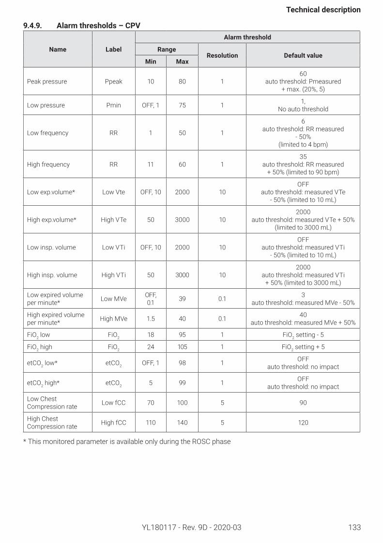
133
Technicaldescription
YL180117 - Rev. 9D - 2020-03
9.4.9. Alarmthresholds–CPV
Name Label
Alarmthreshold
RangeResolution Defaultvalue
Min Max
Peak pressure Ppeak 10 80 160
auto threshold: Pmeasured + max. (20%, 5)
Low pressure Pmin OFF, 1 75 1 1, No auto threshold
Low frequency RR 1 50 1
6 auto threshold: RR measured
- 50% (limited to 4 bpm)
High frequency RR 11 60 135
auto threshold: RR measured + 50% (limited to 90 bpm)
Low exp.volume* Low Vte OFF, 10 2000 10OFF
auto threshold: measured VTe - 50% (limited to 10 mL)
High exp.volume* High VTe 50 3000 102000
auto threshold: measured VTe + 50% (limited to 3000 mL)
Low insp. volume Low VTi OFF, 10 2000 10OFF
auto threshold: measured VTi - 50% (limited to 10 mL)
High insp. volume High VTi 50 3000 102000
auto threshold: measured VTi + 50% (limited to 3000 mL)
Low expired volume per minute* Low MVe OFF,
0.1 39 0.1 3 auto threshold: measured MVe - 50%
High expired volume per minute* High MVe 1.5 40 0.1 40
auto threshold: measured MVe + 50%
FiO2 low FiO2 18 95 1 FiO2 setting - 5
FiO2 high FiO2 24 105 1 FiO2 setting + 5
etCO2 low* etCO2 OFF, 1 98 1 OFF auto threshold: no impact
etCO2 high* etCO2 5 99 1 OFF auto threshold: no impact
Low Chest Compression rate Low fCC 70 100 5 90
High Chest Compression rate High fCC 110 140 5 120
* This monitored parameter is available only during the ROSC phase
134
Monnal T60
YL180117 - Rev. 9D - 2020-03
9.5. Bibliography
• Martin J. Tobin, Principles and Practice of Mechanical Ventilation. Second edition, McGraw-Hill Inc., 2006.• Minaret G.; Richard J.-C.; Ventilation mécanique: modes de référence. ITBM-RBM Volume 26, Issue 1, Jan-uary 2005, Pages 14-18.• ChatburnRL.Classificationofventilatormodes:updateandproposalforimplementation.RespirCare.2007Mar;52(3):301-23.• Esteban A, Anzueto A, Alía I, Gordo F, Apezteguía C, Pálizas F, Cide D, Goldwaser R, Soto L, Buge-do G, Rodrigo C, Pimentel J, Raimondi G, Tobin MJ. How is mechanical ventilation employed in the in-tensive care unit? An international utilization review. Am J Respir Crit Care Med. 2000 May;161(5): 1450-8.• Esteban A, Anzueto A, Frutos F, Alía I, Brochard L, Stewart TE, Benito S, Epstein SK, Apezteguía C, Nightingale P, Arroliga AC, Tobin MJ; Mechanical Ventilation International Study Group. Characteristics and outcomes in adult patients receiving mechanical ventilation: a 28-day international study. JAMA. 2002 Jan 16;287(3):345-55.• S. Jaber, M. Sebbane, D. Verzilli, P. Courouble, G. Chanques, J.J. Eledjam, Les nouveaux modes ventilatoires: avancée ou gadget? Journées Méditerranéennes d’Anesthésie Réanimation et Urgences 2006.• Coutant G., Réanimation-La ventilation artificielle. http://www.infirmiers.com/etudiants-en-ifsi/cours/cours-reanimation-la-ventilation-artificielle.html• LaurentBrochard,AlainMercat,Jean-ChristopheM.Richard.Ventilationartificielle:De laphysiologieà lapratique. Collection Manuel d’anesthésie, de réanimation et d’urgences. Elsevier Masson, 2008.• J. Roeseler, J-B Michotte , A.F.De Ranter, S. Delaere, P.F.Laterre, M.Reynaert, Différentes techniques de ven-tilation. Cliniques universitaires Saint-Luc Soins intensifs C. p. 66-110• Fernandez R. Blanch L. Ventilation assistée contrôlée intermittente. In: L. Brochard and J. Mancebo, Editors, Ventilationartificielleprincipesetapplications,ArnetteEd,Paris(1994),pp.121–132.• Corinne Taniguchi, Raquel C Eid, Cilene Saghabi, Rogério Souza, Eliezer Silva, Elias Knobel, Ângela T Paes, and Carmen S Barbas. Automatic versus manual pressure support reduction in the weaning of post-operative patients: a randomised controlled trial. Crit Care. 2009; 13(1): R6.• Fourcade, Modes AI VT et AV APS en ventilation non invasive. 17ème journée JARCA 2008• Storre JH, Seuthe B, Fiechter R, Milioglou S, Dreher M, Sorichter S, Windisch W. Average volume-assured pressure support in obesity hypoventilation: A randomized crossover trial. Chest. 2006 Sep;130(3):815-2• BrochardL.,IsabeyD.Laventilationnoninvasive.In:L.BrochardandJ.Mancebo,Editors,Ventilationartifi-cielle principes et applications, Arnette Ed, Paris (1994), pp. 241–259 1
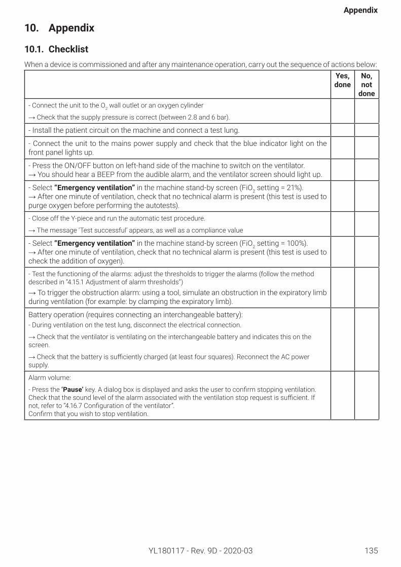
135
Appendix
YL180117 - Rev. 9D - 2020-03
10. Appendix
10.1. ChecklistWhen a device is commissioned and after any maintenance operation, carry out the sequence of actions below:
Yes,done
No,not
done- Connect the unit to the O2 wall outlet or an oxygen cylinder
→ Check that the supply pressure is correct (between 2.8 and 6 bar).
- Install the patient circuit on the machine and connect a test lung.
- Connect the unit to the mains power supply and check that the blue indicator light on the front panel lights up.
- Press the ON/OFF button on left-hand side of the machine to switch on the ventilator.→ You should hear a BEEP from the audible alarm, and the ventilator screen should light up.
- Select “Emergencyventilation” in the machine stand-by screen (FiO2setting=21%).→ After one minute of ventilation, check that no technical alarm is present (this test is used to purge oxygen before performing the autotests).
- Close off the Y-piece and run the automatic test procedure.
→ The message ‘Test successful’ appears, as well as a compliance value
- Select “Emergencyventilation” in the machine stand-by screen (FiO2setting=100%).→ After one minute of ventilation, check that no technical alarm is present (this test is used to check the addition of oxygen).
- Test the functioning of the alarms: adjust the thresholds to trigger the alarms (follow the method described in “4.15.1 Adjustment of alarm thresholds”)→ To trigger the obstruction alarm: using a tool, simulate an obstruction in the expiratory limb during ventilation (for example: by clamping the expiratory limb).
Battery operation (requires connecting an interchangeable battery):- During ventilation on the test lung, disconnect the electrical connection.
→ Check that the ventilator is ventilating on the interchangeable battery and indicates this on the screen.
→Checkthatthebatteryissufficientlycharged(atleastfoursquares).ReconnecttheACpowersupply.
Alarm volume:
- Press the ‘Pause’key.Adialogboxisdisplayedandaskstheusertoconfirmstoppingventilation.Checkthatthesoundlevelofthealarmassociatedwiththeventilationstoprequestissufficient.Ifnot, refer to “4.16.7Configurationoftheventilator”. Confirmthatyouwishtostopventilation.
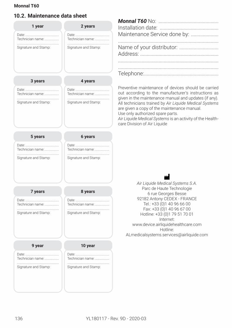
136
Monnal T60
YL180117 - Rev. 9D - 2020-03
10.2. Maintenancedatasheet
Air Liquide Medical Systems S.A.Parc de Haute Technologie
6 rue Georges Besse92182 Antony CEDEX - FRANCE
Tel.: +33 (0)1 40 96 66 00Fax: +33 (0)1 40 96 67 00
Hotline: +33 (0)1 79 51 70 01Internet:
www.device.airliquidehealthcare.comHotline:
1 year
Date: ........................................Technician name: ...................................................................Signature and Stamp:
2 years
Date: ........................................Technician name: ...................................................................Signature and Stamp:
3 years
Date: ........................................Technician name: ...................................................................Signature and Stamp:
4 years
Date: ........................................Technician name: ...................................................................Signature and Stamp:
5 years
Date: ........................................Technician name: ...................................................................Signature and Stamp:
6 years
Date: ........................................Technician name: ...................................................................Signature and Stamp:
7 years
Date: ........................................Technician name: ...................................................................Signature and Stamp:
8 years
Date: ........................................Technician name: ...................................................................Signature and Stamp:
9 year
Date: ........................................Technician name: ...................................................................Signature and Stamp:
10 year
Date: ........................................Technician name: ...................................................................Signature and Stamp:
Monnal T60 No: ..............................................Installation date: .............................................Maintenance Service done by: ..................................................................................................Name of your distributor: ..............................Address: ......................................................................................................................................................................................................................Telephone: .........................................................
Preventive maintenance of devices should be carried out according to the manufacturer’s instructions as given in the maintenance manual and updates (if any). All technicians trained by Air Liquide Medical Systems are given a copy of the maintenance manual.Use only authorized spare parts.Air Liquide Medical Systems is an activity of the Health-care Division of Air Liquide
137
Appendix
YL180117 - Rev. 9D - 2020-03
10.3. Troubleshooting
10.3.1. Introduction
This section helps users to better identify and understand some of the issues that may occur when using the Monnal T60 ventilator.If the problem persists, do not attempt to open the device. Contact your technical service, Air Liquide Medical Systems or your Air Liquide Medical Systems distributor.
Most of the resolution steps described cannot be performed if the device is in use on a patient.
This list is not exhaustive. It presents some known issues. For more information, see “5.7. Table of alarms”, page 76.
Procedureforreportinganissue
These elements should be provided when reporting a technical event:• Serial number of the ventilator• Information about the expiratory valve : serial number, lot number, reusable or single-use;• Description of the problem and the context of the event• Informationandphotosconcerningtheconfigurationandconsumablesused:lotnumber,condition;• Files to be extracted from the ventilator (see “4.16.6. Data transfer”, page 64): Black Box, History, Trends. Use a USB stick with a capacity of no more than 2 GB.• For external power supply issues : (see “10.3.9. External power supply failure”, page 144) : Is the holding clamp in place? Is the cord or block damaged?10.3.2. Autotestsfailure:“Circuitresistancecouldnotbecalculated
Problem
If the autotests fail with the error message “Circuit resistance could not be calculated”.
Probablecauses
The inspiratory and expiratory resistance are measured during the autotests in order to allow leak compensa-tion for resistance.The causes of the message «Circuit resistance could not be calculated» may come from:• Resistancesgeneratedbyfiltersandaccessorieswhichareabovethespecificationlimits• Inadequate seal and/orwrong positioning of consumables (patient circuit, filter, expiratory valve and itsmembrane, black lip seal, etc.)• Inadequate seal (black lip seal, membrane) between the expiratory valve and the ventilator
Troubleshootingsteps
1. Check that the selected patient category matches the patient circuit.2. Checkthattheconsumablesareinstalledproperly,andthattheydonotcauseanyleaks:patientcircuit,filter,expiratory valve and its membrane, black lip seal.3. Ensurethatthefiltersandotheraccessoriesuseddon’tgenerateexcessiveresistance.Resistancevaluesarementionedinthespecificationsoftheconsumables.
Humidity and nebulization can increase the resistance of the filters.
To see the specified limits for resistances, see 9.4.3.64. If the problem persists contact Air Liquide Medical Systems or your Air Liquide Medical Systems distributor.
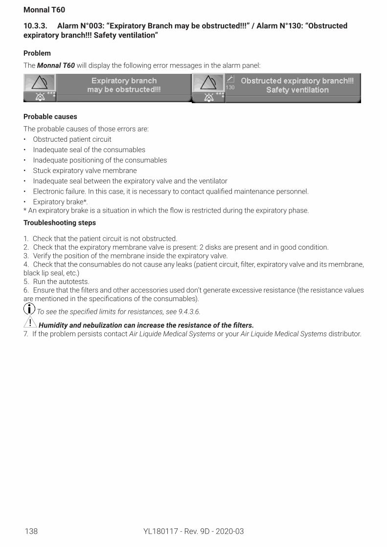
138
Monnal T60
YL180117 - Rev. 9D - 2020-03
10.3.3. AlarmN°003:“ExpiratoryBranchmaybeobstructed!!!”/AlarmN°130:“Obstructedexpiratorybranch!!!Safetyventilation”
Problem
The Monnal T60 will display the following error messages in the alarm panel:
Probablecauses
The probable causes of those errors are:• Obstructed patient circuit• Inadequate seal of the consumables• Inadequate positioning of the consumables• Stuck expiratory valve membrane• Inadequate seal between the expiratory valve and the ventilator• Electronicfailure.Inthiscase,itisnecessarytocontactqualifiedmaintenancepersonnel.• Expiratory brake*. *Anexpiratorybrakeisasituationinwhichtheflowisrestrictedduringtheexpiratoryphase.
Troubleshootingsteps
1. Check that the patient circuit is not obstructed.2. Check that the expiratory membrane valve is present: 2 disks are present and in good condition.3. Verify the position of the membrane inside the expiratory valve.4. Checkthattheconsumablesdonotcauseanyleaks(patientcircuit,filter,expiratoryvalveanditsmembrane,black lip seal, etc.)5. Run the autotests.6. Ensurethatthefiltersandotheraccessoriesuseddon’tgenerateexcessiveresistance(theresistancevaluesarementionedinthespecificationsoftheconsumables).
To see the specified limits for resistances, see 9.4.3.6.
Humidity and nebulization can increase the resistance of the filters.7. If the problem persists contact Air Liquide Medical Systems or your Air Liquide Medical Systems distributor.
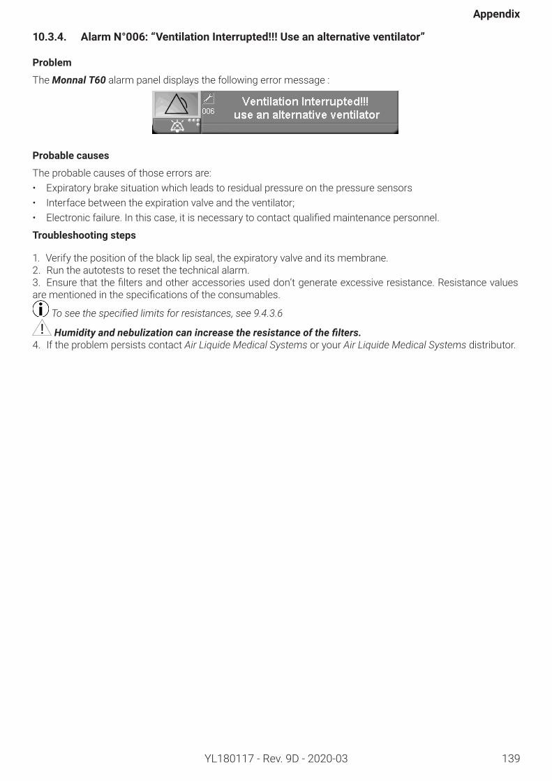
139
Appendix
YL180117 - Rev. 9D - 2020-03
10.3.4. AlarmN°006:“VentilationInterrupted!!!Useanalternativeventilator”
Problem
The Monnal T60 alarm panel displays the following error message :
Probablecauses
The probable causes of those errors are:• Expiratory brake situation which leads to residual pressure on the pressure sensors• Interface between the expiration valve and the ventilator;• Electronicfailure.Inthiscase,itisnecessarytocontactqualifiedmaintenancepersonnel.
Troubleshootingsteps
1. Verify the position of the black lip seal, the expiratory valve and its membrane.2. Run the autotests to reset the technical alarm.3. Ensurethatthefiltersandotheraccessoriesuseddon’tgenerateexcessiveresistance.Resistancevaluesarementionedinthespecificationsoftheconsumables.
To see the specified limits for resistances, see 9.4.3.6
Humidity and nebulization can increase the resistance of the filters.4. If the problem persists contact Air Liquide Medical Systems or your Air Liquide Medical Systems distributor.
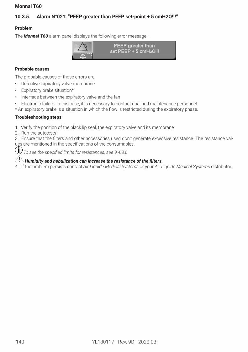
140
Monnal T60
YL180117 - Rev. 9D - 2020-03
10.3.5. AlarmN°021:“PEEPgreaterthanPEEPset-point+5cmH2O!!!”
Problem
The Monnal T60 alarm panel displays the following error message :
Probablecauses
The probable causes of those errors are:• Defective expiratory valve membrane• Expiratory brake situation*• Interface between the expiratory valve and the fan• Electronicfailure.Inthiscase,itisnecessarytocontactqualifiedmaintenancepersonnel.*Anexpiratorybrakeisasituationinwhichtheflowisrestrictedduringtheexpiratoryphase.
Troubleshootingsteps
1. Verify the position of the black lip seal, the expiratory valve and its membrane2. Run the autotests3. Ensurethatthefiltersandotheraccessoriesuseddon’tgenerateexcessiveresistance.Theresistanceval-uesarementionedinthespecificationsoftheconsumables.
To see the specified limits for resistances, see 9.4.3.6
Humidity and nebulization can increase the resistance of the filters.4. If the problem persists contact Air Liquide Medical Systems or your Air Liquide Medical Systems distributor.
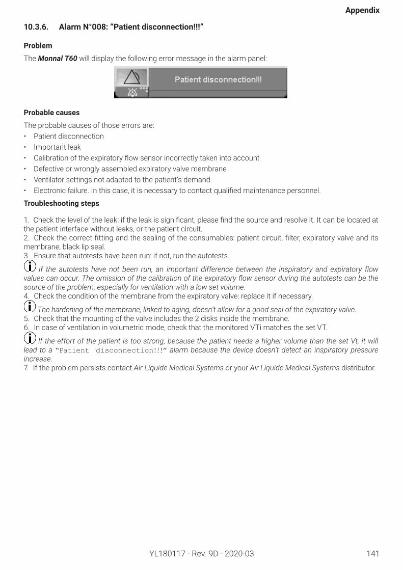
141
Appendix
YL180117 - Rev. 9D - 2020-03
10.3.6. AlarmN°008:“Patientdisconnection!!!”
Problem
The Monnal T60 will display the following error message in the alarm panel:
Probablecauses
The probable causes of those errors are:• Patient disconnection• Important leak• Calibrationoftheexpiratoryflowsensorincorrectlytakenintoaccount• Defective or wrongly assembled expiratory valve membrane • Ventilator settings not adapted to the patient’s demand• Electronicfailure.Inthiscase,itisnecessarytocontactqualifiedmaintenancepersonnel.
Troubleshootingsteps
1. Checktheleveloftheleak:iftheleakissignificant,pleasefindthesourceandresolveit.Itcanbelocatedatthe patient interface without leaks, or the patient circuit.2. Checkthecorrectfittingandthesealingoftheconsumables:patientcircuit,filter,expiratoryvalveanditsmembrane, black lip seal.3. Ensure that autotests have been run: if not, run the autotests.
If the autotests have not been run, an important difference between the inspiratory and expiratory flow values can occur. The omission of the calibration of the expiratory flow sensor during the autotests can be the source of the problem, especially for ventilation with a low set volume.4. Check the condition of the membrane from the expiratory valve: replace it if necessary.
The hardening of the membrane, linked to aging, doesn’t allow for a good seal of the expiratory valve. 5. Check that the mounting of the valve includes the 2 disks inside the membrane.6. In case of ventilation in volumetric mode, check that the monitored VTi matches the set VT.
If the effort of the patient is too strong, because the patient needs a higher volume than the set Vt, it will lead to a “Patient disconnection!!!” alarm because the device doesn’t detect an inspiratory pressure increase.7. If the problem persists contact Air Liquide Medical Systems or your Air Liquide Medical Systems distributor.
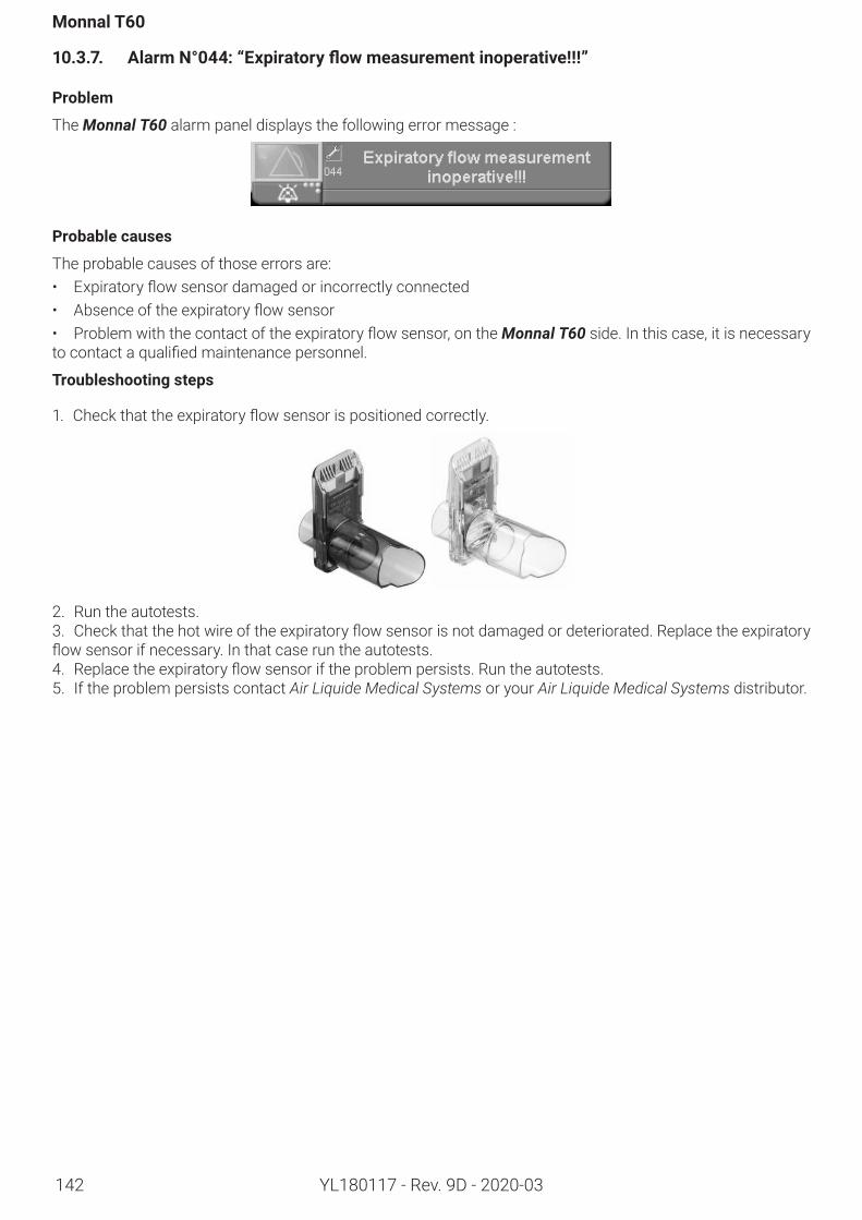
142
Monnal T60
YL180117 - Rev. 9D - 2020-03
10.3.7. AlarmN°044:“Expiratoryflowmeasurementinoperative!!!”
Problem
The Monnal T60 alarm panel displays the following error message :
Probablecauses
The probable causes of those errors are:• Expiratoryflowsensordamagedorincorrectlyconnected• Absenceoftheexpiratoryflowsensor• Problemwiththecontactoftheexpiratoryflowsensor,ontheMonnal T60 side. In this case, it is necessary tocontactaqualifiedmaintenancepersonnel.
Troubleshootingsteps
1. Checkthattheexpiratoryflowsensorispositionedcorrectly.
2. Run the autotests.3. Checkthatthehotwireoftheexpiratoryflowsensorisnotdamagedordeteriorated.Replacetheexpiratoryflowsensorifnecessary.Inthatcaseruntheautotests.4. Replacetheexpiratoryflowsensoriftheproblempersists.Runtheautotests.5. If the problem persists contact Air Liquide Medical Systems or your Air Liquide Medical Systems distributor.
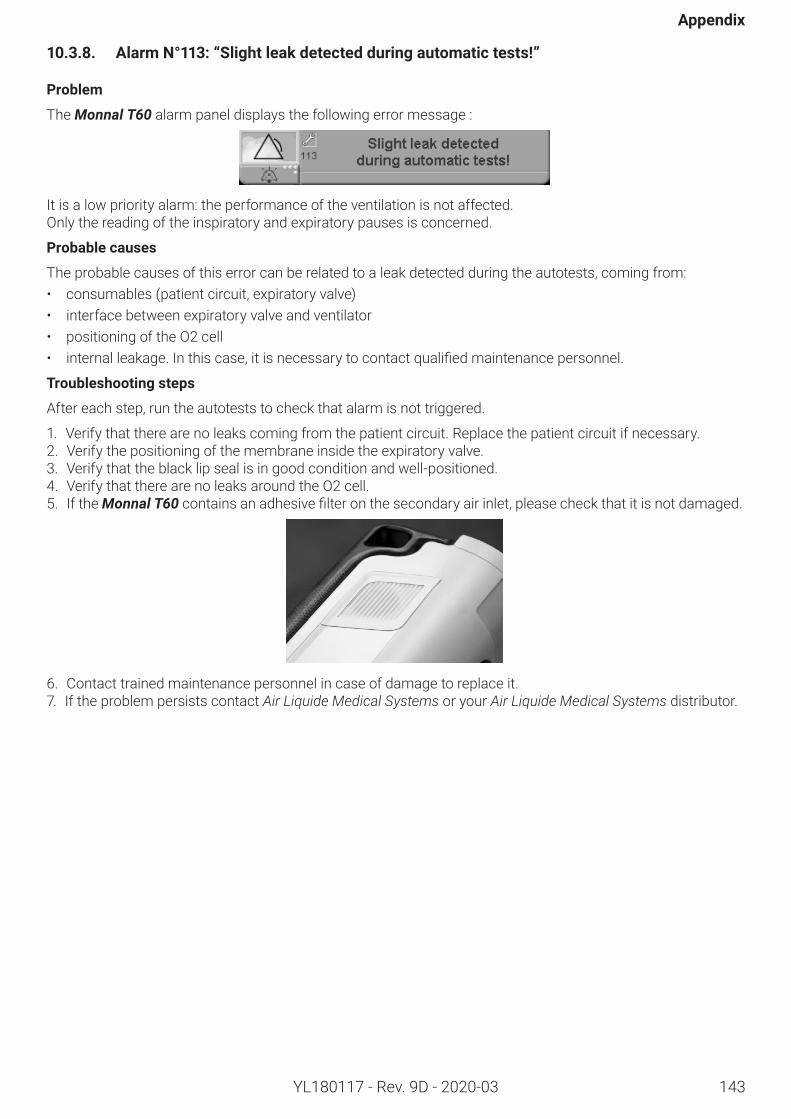
143
Appendix
YL180117 - Rev. 9D - 2020-03
10.3.8. AlarmN°113:“Slightleakdetectedduringautomatictests!”
Problem
The Monnal T60 alarm panel displays the following error message :
It is a low priority alarm: the performance of the ventilation is not affected.Only the reading of the inspiratory and expiratory pauses is concerned.
Probablecauses
The probable causes of this error can be related to a leak detected during the autotests, coming from:• consumables (patient circuit, expiratory valve)• interface between expiratory valve and ventilator• positioning of the O2 cell• internalleakage.Inthiscase,itisnecessarytocontactqualifiedmaintenancepersonnel.
Troubleshootingsteps
After each step, run the autotests to check that alarm is not triggered.
1. Verify that there are no leaks coming from the patient circuit. Replace the patient circuit if necessary.2. Verify the positioning of the membrane inside the expiratory valve.3. Verify that the black lip seal is in good condition and well-positioned.4. Verify that there are no leaks around the O2 cell.5. If the Monnal T60containsanadhesivefilteronthesecondaryairinlet,pleasecheckthatitisnotdamaged.
6. Contact trained maintenance personnel in case of damage to replace it.7. If the problem persists contact Air Liquide Medical Systems or your Air Liquide Medical Systems distributor.
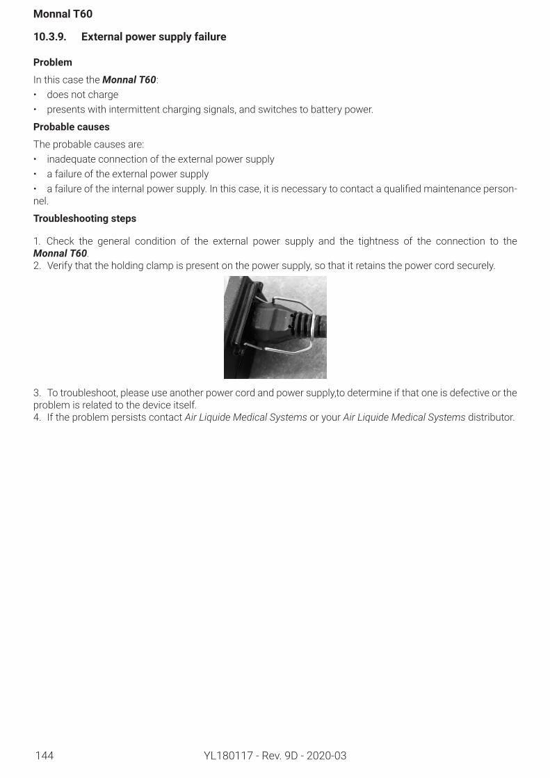
144
Monnal T60
YL180117 - Rev. 9D - 2020-03
10.3.9. Externalpowersupplyfailure
Problem
In this case the Monnal T60:• does not charge• presents with intermittent charging signals, and switches to battery power.
Probablecauses
The probable causes are:• inadequate connection of the external power supply• a failure of the external power supply• afailureoftheinternalpowersupply.Inthiscase,itisnecessarytocontactaqualifiedmaintenanceperson-nel.
Troubleshootingsteps
1. Check the general condition of the external power supply and the tightness of the connection to the Monnal T60.2. Verify that the holding clamp is present on the power supply, so that it retains the power cord securely.
3. To troubleshoot, please use another power cord and power supply,to determine if that one is defective or the problem is related to the device itself.4. If the problem persists contact Air Liquide Medical Systems or your Air Liquide Medical Systems distributor.
145
Appendix
YL180117 - Rev. 9D - 2020-03
10.3.10. Differencebetweenthesetandthemonitoredvolumesinnon-invasiveventilation
Problem
A difference is detected between the set VT and monitored VT in non-invasive ventilation.
Probablecauses
The probable causes of this problem may come from:• Not performing the autotests• Leaks• Expiratoryflowsensor• Drift of the calibration of the Monnal T60.Inthiscase,itisnecessarytocontactqualifiedmaintenanceper-sonnel.
Troubleshootingsteps
1. Check the level of leakage. If the leak level is high, look for the source of the leak and solve it. It may be at the patient interface, or at the patient circuit.2. Ensurethattheautotestshavebeenrun.Duringthisphase,theexpiratoryflowsensoriscalibrated.3. If it has not been performed, set the Monnal T60totheconfigurationusedinventilation,thenruntheauto-tests.4. Run ventilation using a test lung, and check that the set values match the monitored values.5. If the values are consistent, this means that there is probably a leak, and that it is after the Y-piece. For ex-ample check the patient interface.6. Repeatthepreviousstepsafterthereplacementofthevalveandtheexpiratoryflowsensor.7. If the problem persists contact Air Liquide Medical Systems or your Air Liquide Medical Systems distributor.
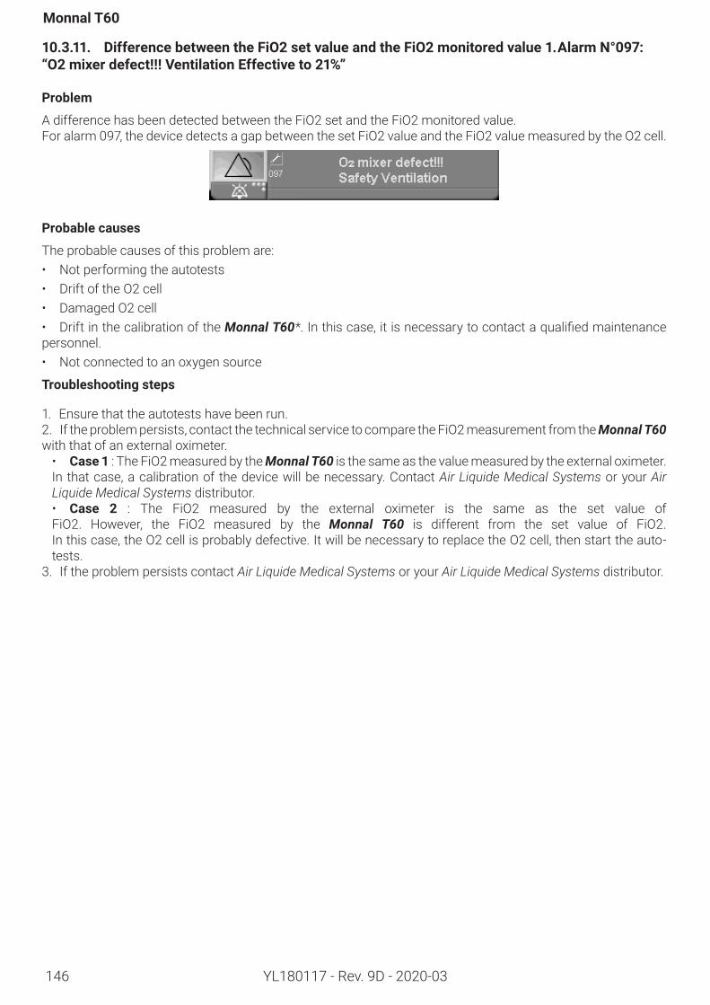
146
Monnal T60
YL180117 - Rev. 9D - 2020-03
10.3.11. DifferencebetweentheFiO2setvalueandtheFiO2monitoredvalue1.AlarmN°097:“O2mixerdefect!!!VentilationEffectiveto21%”
Problem
A difference has been detected between the FiO2 set and the FiO2 monitored value.For alarm 097, the device detects a gap between the set FiO2 value and the FiO2 value measured by the O2 cell.
Probablecauses
The probable causes of this problem are:• Not performing the autotests• Drift of the O2 cell• Damaged O2 cell• Drift in the calibration of the Monnal T60*.Inthiscase,itisnecessarytocontactaqualifiedmaintenancepersonnel.• Not connected to an oxygen source
Troubleshootingsteps
1. Ensure that the autotests have been run.2. If the problem persists, contact the technical service to compare the FiO2 measurement from the Monnal T60 with that of an external oximeter.• Case 1 : The FiO2 measured by the Monnal T60 is the same as the value measured by the external oximeter. In that case, a calibration of the device will be necessary. Contact Air Liquide Medical Systems or your Air Liquide Medical Systems distributor.• Case 2 : The FiO2 measured by the external oximeter is the same as the set value of FiO2. However, the FiO2 measured by the Monnal T60 is different from the set value of FiO2. In this case, the O2 cell is probably defective. It will be necessary to replace the O2 cell, then start the auto-tests.
3. If the problem persists contact Air Liquide Medical Systems or your Air Liquide Medical Systems distributor.
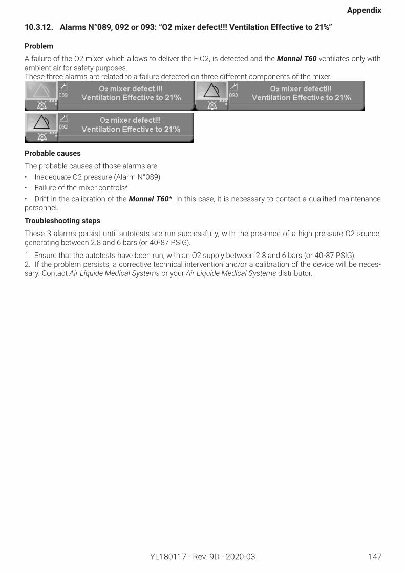
147
Appendix
YL180117 - Rev. 9D - 2020-03
10.3.12. AlarmsN°089,092or093:“O2mixerdefect!!!VentilationEffectiveto21%”
Problem
A failure of the O2 mixer which allows to deliver the FiO2, is detected and the Monnal T60 ventilates only with ambient air for safety purposes.These three alarms are related to a failure detected on three different components of the mixer.
Probablecauses
The probable causes of those alarms are:• Inadequate O2 pressure (Alarm N°089)• Failure of the mixer controls*• Drift in the calibration of the Monnal T60*.Inthiscase,itisnecessarytocontactaqualifiedmaintenancepersonnel.
Troubleshootingsteps
These 3 alarms persist until autotests are run successfully, with the presence of a high-pressure O2 source, generating between 2.8 and 6 bars (or 40-87 PSIG).
1. Ensure that the autotests have been run, with an O2 supply between 2.8 and 6 bars (or 40-87 PSIG).2. If the problem persists, a corrective technical intervention and/or a calibration of the device will be neces-sary. Contact Air Liquide Medical Systems or your Air Liquide Medical Systems distributor.
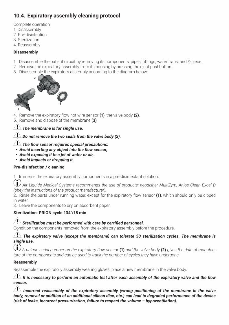
10.4. ExpiratoryassemblycleaningprotocolComplete operation: 1. Disassembly2. Pre-disinfection3. Sterilization4. Reassembly
Disassembly
1. Disassemblethepatientcircuitbyremovingitscomponents:pipes,fittings,watertraps,andY-piece.2. Remove the expiratory assembly from its housing by pressing the eject pushbutton.3. Disassemble the expiratory assembly according to the diagram below:
1
2
3
4. Removetheexpiratoryflowhotwiresensor(1), the valve body (2).5. Remove and dispose of the membrane (3).
The membrane is for single use.
Do not remove the two seals from the valve body (2).
The flow sensor requires special precautions: • Avoid inserting any object into the flow sensor,• Avoid exposing it to a jet of water or air,• Avoid impacts or dropping it.
Pre-disinfection/cleaning
1. Immerse the expiratory assembly components in a pre-disinfectant solution.
Air Liquide Medical Systems recommends the use of products: neodisher MultiZym, Anios Clean Excel D (obey the instructions of the product manufacturer). 2. Rinsethepartsunderrunningwater,exceptfortheexpiratoryflowsensor(1), which should only be dipped in water.3. Leave the components to dry on absorbent paper.
Sterilization:PRIONcycle134°/18min
Sterilization must be performed with care by certified personnel. Condition the components removed from the expiratory assembly before the procedure.
The expiratory valve (except the membrane) can tolerate 50 sterilization cycles. The membrane is single use.
A unique serial number on the expiratory flow sensor (1) and the valve body (2) gives the date of manufac-ture of the components and can be used to track the number of cycles they have undergone.
Reassembly
Reassemble the expiratory assembly wearing gloves: place a new membrane in the valve body.
It is necessary to perform an automatic test after each assembly of the expiratory valve and the flow sensor.
Incorrect reassembly of the expiratory assembly (wrong positioning of the membrane in the valve body, removal or addition of an additional silicon disc, etc.) can lead to degraded performance of the device (risk of leaks, incorrect pressurization, failure to respect the volume – hypoventilation).
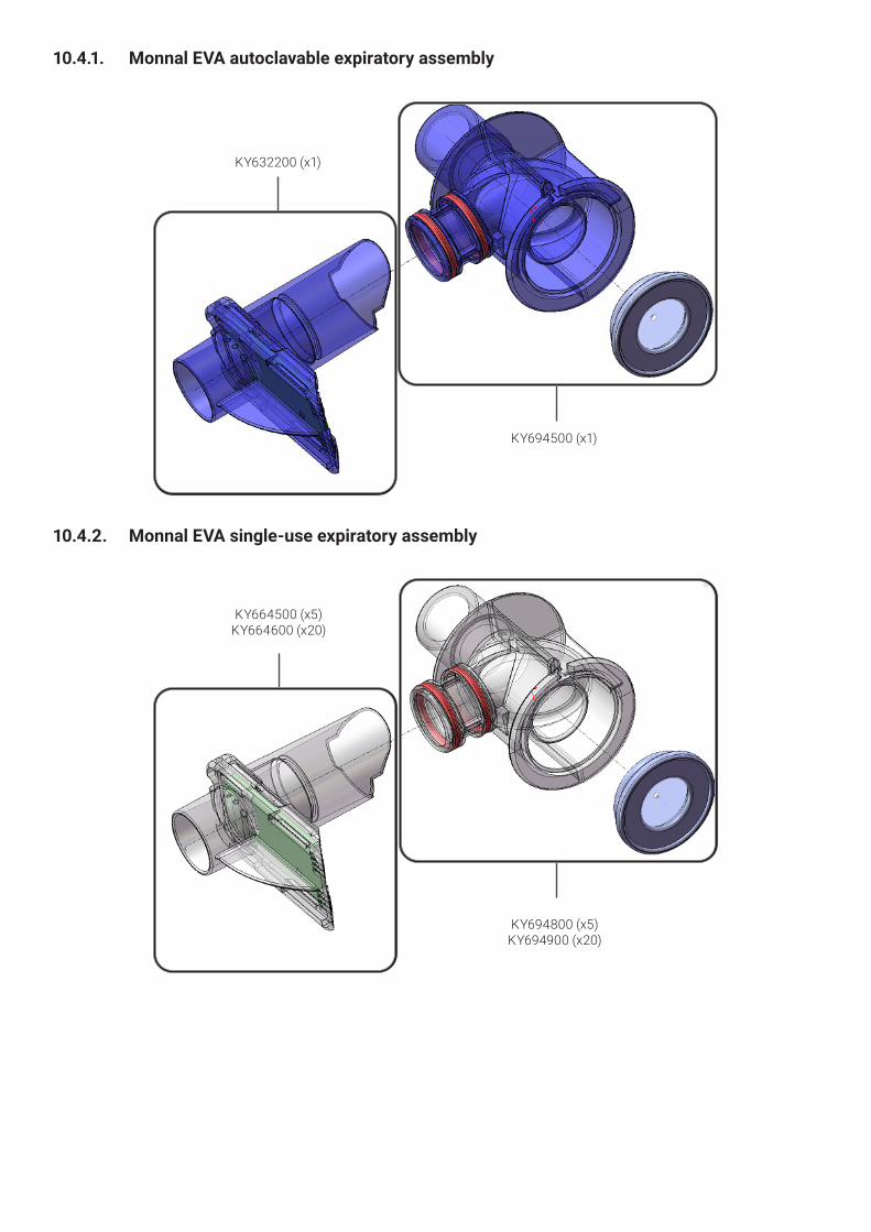
10.4.1. MonnalEVAautoclavableexpiratoryassembly
KY632200 (x1)
KY694500 (x1)
10.4.2. MonnalEVAsingle-useexpiratoryassembly
KY664500 (x5)KY664600 (x20)
KY694800 (x5)KY694900 (x20)

www.airliquidehealthcare.ca
UM000115
V2.7.xI9D
ContactAir Liquide Healthcare6990 Creditview Road, Unit 6Mississauga, Ontario L5N 8R9