Embed Size (px)
Citation preview
VISO SYSTEMS
CALI-T50 Reference Lamp User Manual
Revision: 2020-03
Congratulations on purchasing your new Viso Systems product. Before using this
product, please read the Safety Information.
This manual contains descriptions and troubleshooting necessary to install and
operate your new Viso Systems product. Please review this manual thoroughly to
ensure proper installation and operation.
For news, Q&A and support at Viso Systems, visit our website at
www.visosystems.com
Other manuals in this series (the latest version can be downloaded from
www.visosystem.com):
▪ LabSpion Assembly Manual
▪ LabSpion User Manual
▪ BaseSpion Assembly Manual
▪ BaseSpion User Manual
▪ LightSpion User Manual
▪ LightSpion Extender User Manual
▪ LabFlicker User Manual
▪ Light Inspector (software) Manual
3
Contents
Introduction .................................................................................. 4
About this document .......................................................................................... 4
Safety information .............................................................................................. 4 Preventing electric shocks ................................................................................... 4
Disposing of this product..................................................................................... 4
About Calibration and Light Sources .............................................. 5
About the CALI-T50 ............................................................................................. 6
Dimensions ......................................................................................................... 6
CALI-T50 Package Contents ................................................................................. 7 The Test Certificate ............................................................................................. 8
Calibrating a Viso System ............................................................... 9
LabSpion: Mounting the CALI-T50 and aligning the sensor .................................. 9
Measuring the distance .......................................................................................10
BaseSpion: Mounting the CALI-T50 ................................................................... 10
LightSpion: Mounting the CALI-T50 ................................................................... 11
Connecting Power to the CALI-T50 .................................................................... 12
Warm-up and Stabilization ................................................................................ 12
Making a quick reference check-up of the sensor .............................................. 12
Calibrating the sensor ....................................................................................... 13
Spectrometer Calibration – Step by Step ...................................... 15
4 — CALI-T50 User Manual
Introduction
About this document
These guidelines describe how to use the CALI-T50 as a reference light
source and how to do custom calibrations on Viso Systems goniometer
products.
Safety information
Warning! This product is not for household use.
Read this manual before installing and operating the CALI-T50, follow the
safety warnings listed below, and study all the cautions in the manual.
Preventing electric shocks
Make sure the power supply is always grounded.
Use a source of AC power that complies with the local building and electrical
codes, that has both overload and ground-fault protection.
If the controller or the power supply are in any way damaged, defective,
wet, or show signs of overheating, disconnect the power supply from the AC
power and contact Viso Service for assistance.
Do not install or use the device outdoors. Do not spray with or immerse in
water or any other liquid.
Do not remove any covers or attempt to repair the controller or the power
supply. Refer any service to Viso.
Disposing of this product
Viso products are supplied in compliance with Directive 2002/96/EC of the
European Parliament and of the Council of the European Union on WEEE
(Waste Electrical and Electronic Equipment), as amended by Directive
2003/108/EC, where applicable.
Help preserve the environment! Ensure that this product is recycled at the
end of its lifetime. Your supplier can give details of local arrangements for
the disposal of Viso products.
© 2020 Viso Systems ApS, Denmark
All rights reserved. No part of this manual may be reproduced, in any form or by any means,
without permission in writing from Viso Systems ApS, Denmark. Information subject to change
without notice. Viso Systems ApS and all affiliated companies disclaim liability for any injury,
damage, direct or indirect loss, consequential or economic loss or any other loss occasioned by
the use of, inability to use or reliance on the information contained in this manual.

CALI-T50 User Manual — 5
About Calibration and Light Sources All Viso systems are delivered pre-calibrated but it is possible to make a custom
calibration of the photo spectrometer if desires. This could be necessary if the
system is to be certified by and official agency, which will perform its own calibration
and afterwards issue certification documents.
To make custom calibrations a calibration source must be used, and the spectrum
and the intensity in a point at a certain distance must be known. Such a spectrum is
usually specified as power in uW/cm2/nm as shown below.
Calibration sources can be obtained from a number of suppliers. This manual
describes calibration procedures for the CALI-T50 from Viso Systems which is a
tungsten irradiance lamp. The spectrum of the calibration source is usually provided
in a .lmp file (lamp file).
All CALI-T50 light sources are traceable to Viso’s calibration lamp (a New Port
irradiance lamp with serial SN7-2011 with reference to NIST lamp F-602):
Important:
Calibrations must be made in a dark environment with non-reflective surfaces.
6 — CALI-T50 User Manual
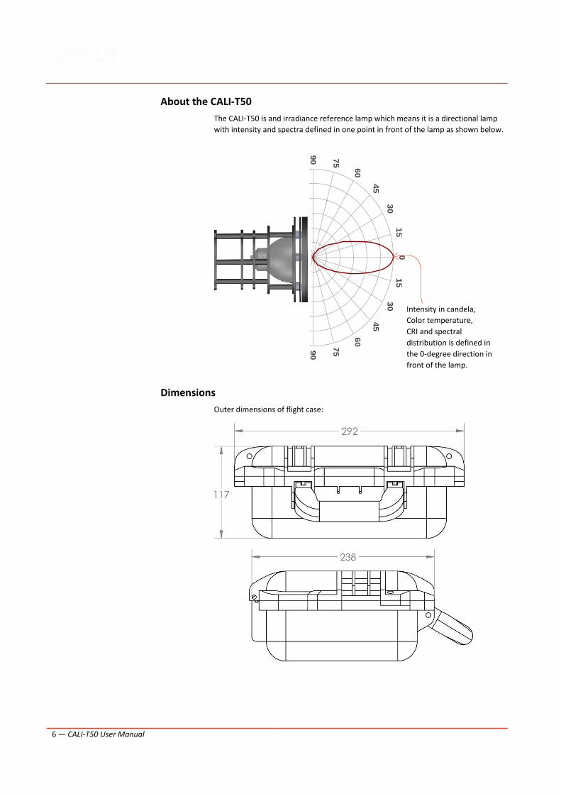
About the CALI-T50
The CALI-T50 is and irradiance reference lamp which means it is a directional lamp
with intensity and spectra defined in one point in front of the lamp as shown below.
Dimensions
Outer dimensions of flight case:
015
30
45
60
7590
105
120
135
150
165
180
165
150
135
120
105
90 75
60
45
30
15
Intensity in candela,
Color temperature,
CRI and spectral
distribution is defined in
the 0-degree direction in
front of the lamp.

CALI-T50 User Manual — 7
Outer dimensions of the light source:
Shipping Packages Shipping Dimensions Shipping Volume Weight
1. CALI-T50 400 x 300 x 250 mm 0.03 m3 2 kg
Total shipping weight: 2 kg
The shipment is done in a total of 1 package.
CALI-T50 Package Contents
▪ Smart suitcase
▪ Mains Power Supply Cable
▪ Light Source supply cable
▪ Test Certificate
▪ Instructions
8 — CALI-T50 User Manual
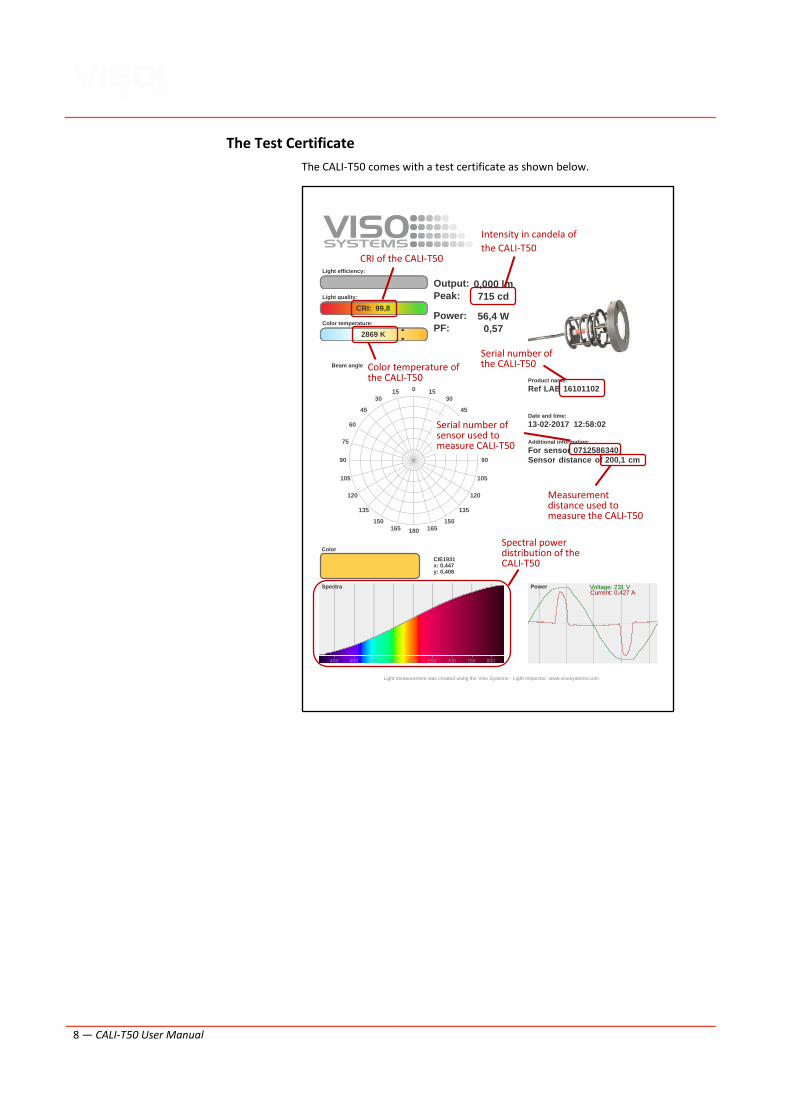
The Test Certificate
The CALI-T50 comes with a test certificate as shown below.
0 1530
45
60
75
90
105
120
135
150165180165
150
135
120
105
90
75
60
45
3015
Light efficiency:
Light quality:
CRI: 99,8
Color temperature:
2869 K
Output: 0,000 lm
Peak: 715 cd
Power: 56,4 W
PF: 0,57
Product name:
Ref LAB 16101102
Date and time:
13-02-2017 12:58:02
Additional information:
For sensor 0712586340
Sensor distance of 200,1 cm
CIE1931x: 0,447y: 0,408
400 450 500 550 600 650 700 750 800
Beam angle
Color
Spectra Power Voltage: 231 VCurrent: 0,427 A
Light measurement was created using the Viso Systems - Light Inspector. www.visosystems.com
CRI of the CALI-T50
Color temperature of the CALI-T50
Intensity in candela of
the CALI-T50
Serial number of the CALI-T50
Serial number of sensor used to measure CALI-T50
Measurement distance used to measure the CALI-T50
Spectral power distribution of the CALI-T50
CALI-T50 User Manual — 9
Calibrating a Viso System Calibration procedures are more or less the same for all Viso systems but mounting
and aligning the CALI-T50 are a little different. This section will describe mounting
and alignment for the three systems first, and then describe the common
procedures.
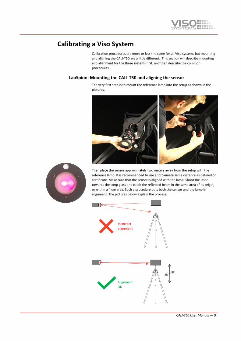
LabSpion: Mounting the CALI-T50 and aligning the sensor
The very first step is to mount the reference lamp into the setup as shown in the
pictures.
Then place the sensor approximately two meters away from the setup with the
reference lamp. It is recommended to use approximate same distance as defined on
certificate. Make sure that the sensor is aligned with the lamp. Shoot the laser
towards the lamp glass and catch the reflected beam in the same area of its origin,
or within a 4 cm area. Such a procedure puts both the sensor and the lamp in
alignment. The pictures below explain the process:
Incorrect
alignment
Alignment
OK
10 — CALI-T50 User Manual
Measuring the distance
When the sensor is aligned relative to the lamp, you can measure the precise
distance between the two components. It should be between 190 and 210 cm
(referring to the certificate).
Now start the distance measurement
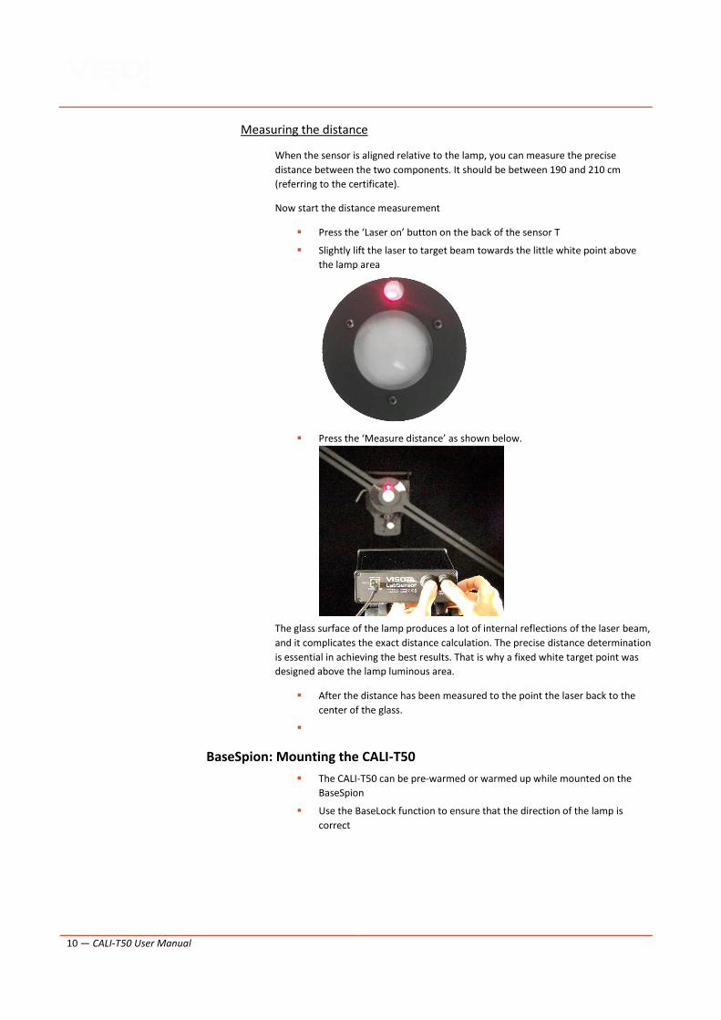
▪ Press the ‘Laser on’ button on the back of the sensor T
▪ Slightly lift the laser to target beam towards the little white point above
the lamp area
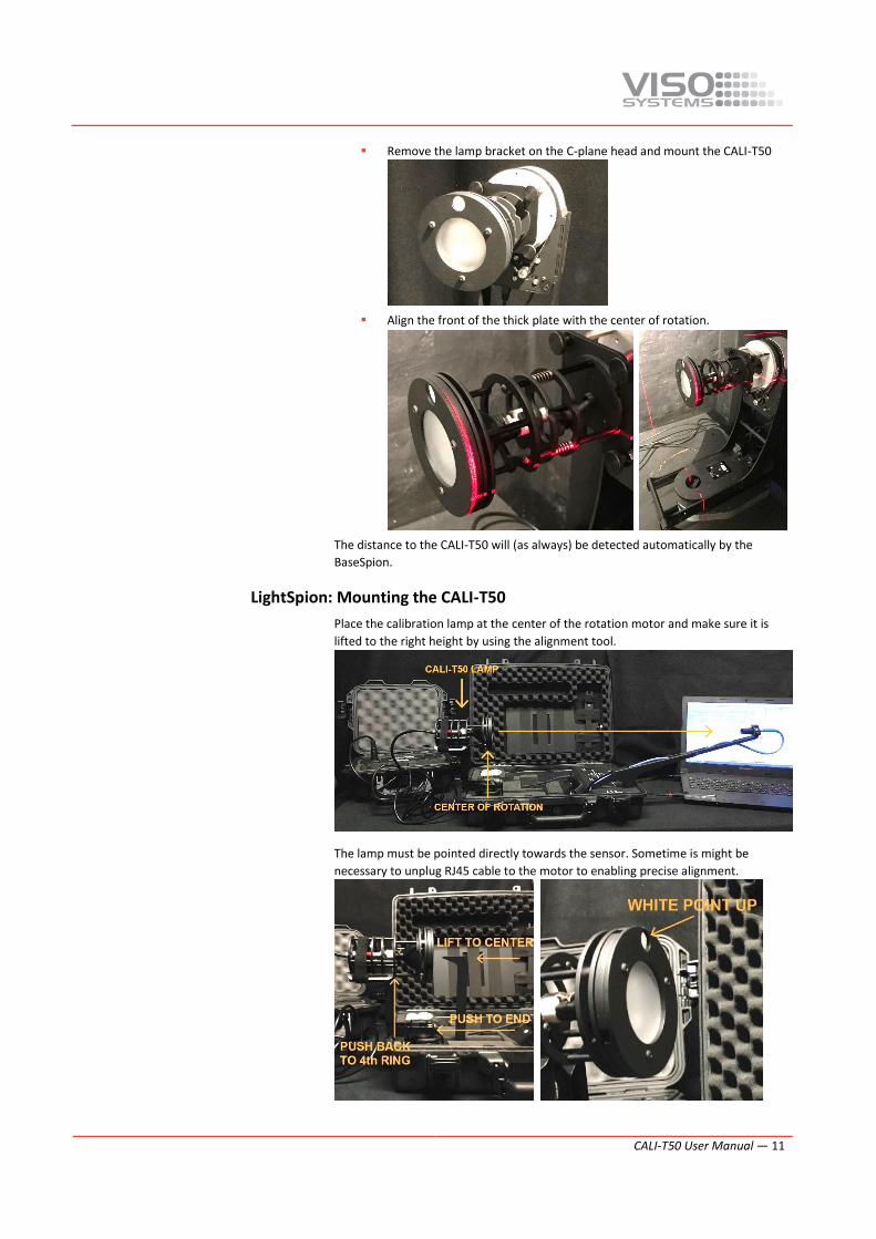
▪ Press the ‘Measure distance’ as shown below.
The glass surface of the lamp produces a lot of internal reflections of the laser beam,
and it complicates the exact distance calculation. The precise distance determination
is essential in achieving the best results. That is why a fixed white target point was
designed above the lamp luminous area.
▪ After the distance has been measured to the point the laser back to the
center of the glass.
▪
BaseSpion: Mounting the CALI-T50
▪ The CALI-T50 can be pre-warmed or warmed up while mounted on the
BaseSpion
▪ Use the BaseLock function to ensure that the direction of the lamp is
correct
CALI-T50 User Manual — 11
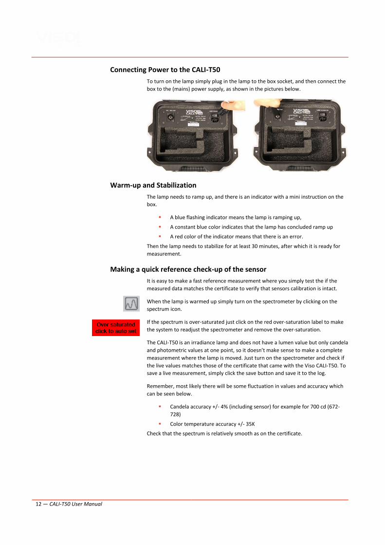
▪ Remove the lamp bracket on the C-plane head and mount the CALI-T50
▪ Align the front of the thick plate with the center of rotation.
The distance to the CALI-T50 will (as always) be detected automatically by the
BaseSpion.
LightSpion: Mounting the CALI-T50
Place the calibration lamp at the center of the rotation motor and make sure it is
lifted to the right height by using the alignment tool.
The lamp must be pointed directly towards the sensor. Sometime is might be
necessary to unplug RJ45 cable to the motor to enabling precise alignment.
12 — CALI-T50 User Manual
Connecting Power to the CALI-T50
To turn on the lamp simply plug in the lamp to the box socket, and then connect the
box to the (mains) power supply, as shown in the pictures below.
Warm-up and Stabilization
The lamp needs to ramp up, and there is an indicator with a mini instruction on the
box.
▪ A blue flashing indicator means the lamp is ramping up,
▪ A constant blue color indicates that the lamp has concluded ramp up
▪ A red color of the indicator means that there is an error.
Then the lamp needs to stabilize for at least 30 minutes, after which it is ready for
measurement.
Making a quick reference check-up of the sensor
It is easy to make a fast reference measurement where you simply test the if the
measured data matches the certificate to verify that sensors calibration is intact.
When the lamp is warmed up simply turn on the spectrometer by clicking on the
spectrum icon.
If the spectrum is over-saturated just click on the red over-saturation label to make
the system to readjust the spectrometer and remove the over-saturation.
The CALI-T50 is an irradiance lamp and does not have a lumen value but only candela
and photometric values at one point, so it doesn’t make sense to make a complete
measurement where the lamp is moved. Just turn on the spectrometer and check if
the live values matches those of the certificate that came with the Viso CALI-T50. To
save a live measurement, simply click the save button and save it to the log.
Remember, most likely there will be some fluctuation in values and accuracy which
can be seen below.
▪ Candela accuracy +/- 4% (including sensor) for example for 700 cd (672-
728)
▪ Color temperature accuracy +/- 35K
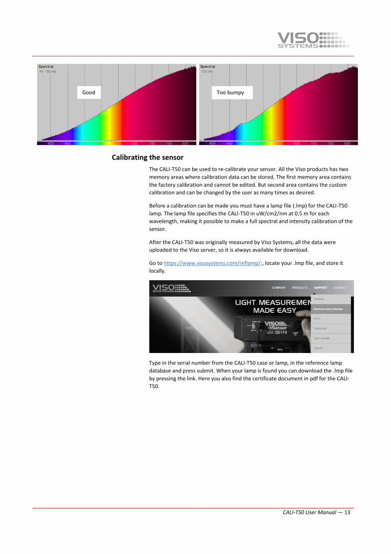
Check that the spectrum is relatively smooth as on the certificate.
CALI-T50 User Manual — 13
Calibrating the sensor
The CALI-T50 can be used to re-calibrate your sensor. All the Viso products has two
memory areas where calibration data can be stored. The first memory area contains
the factory calibration and cannot be edited. But second area contains the custom
calibration and can be changed by the user as many times as desired.
Before a calibration can be made you must have a lamp file (.lmp) for the CALI-T50
lamp. The lamp file specifies the CALI-T50 in uW/cm2/nm at 0.5 m for each
wavelength, making it possible to make a full spectral and intensity calibration of the
sensor.
After the CALI-T50 was originally measured by Viso Systems, all the data were
uploaded to the Viso server, so it is always available for download.
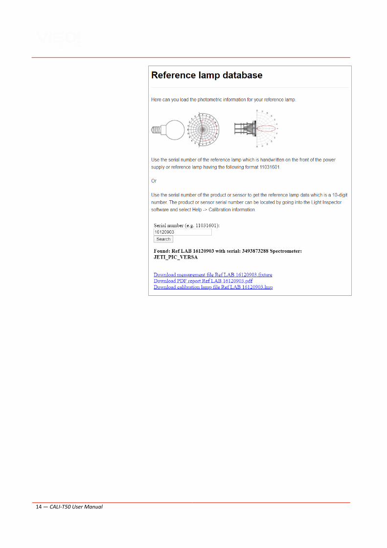
Go to https://www.visosystems.com/reflamp/:, locate your .lmp file, and store it
locally.
Type in the serial number from the CALI-T50 case or lamp, in the reference lamp
database and press submit. When your lamp is found you can download the .lmp file
by pressing the link. Here you also find the certificate document in pdf for the CALI-
T50.
Good Too bumpy
14 — CALI-T50 User Manual
CALI-T50 User Manual — 15
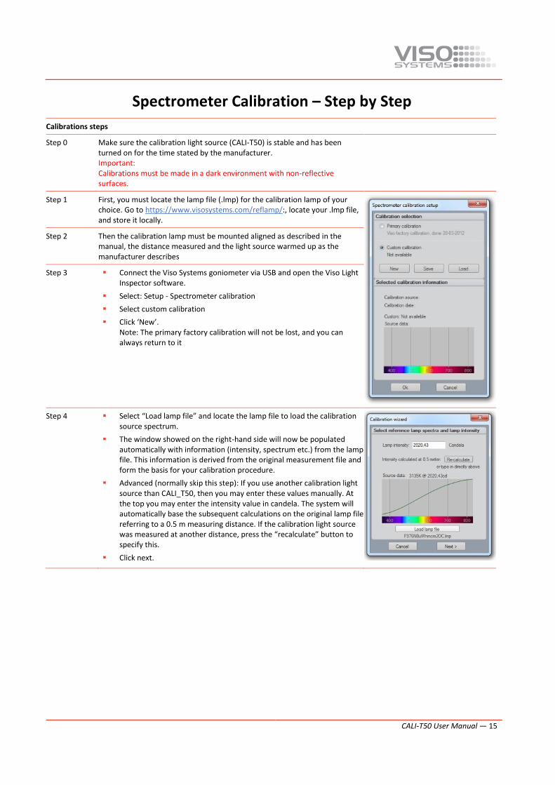
Spectrometer Calibration – Step by Step
Calibrations steps
Step 0 Make sure the calibration light source (CALI-T50) is stable and has been turned on for the time stated by the manufacturer. Important: Calibrations must be made in a dark environment with non-reflective surfaces.
Step 1 First, you must locate the lamp file (.lmp) for the calibration lamp of your choice. Go to https://www.visosystems.com/reflamp/:, locate your .lmp file, and store it locally.
Step 2 Then the calibration lamp must be mounted aligned as described in the manual, the distance measured and the light source warmed up as the manufacturer describes
Step 3 ▪ Connect the Viso Systems goniometer via USB and open the Viso Light Inspector software.
▪ Select: Setup - Spectrometer calibration
▪ Select custom calibration
▪ Click ‘New’. Note: The primary factory calibration will not be lost, and you can always return to it
Step 4 ▪ Select “Load lamp file” and locate the lamp file to load the calibration source spectrum.
▪ The window showed on the right-hand side will now be populated automatically with information (intensity, spectrum etc.) from the lamp file. This information is derived from the original measurement file and form the basis for your calibration procedure.
▪ Advanced (normally skip this step): If you use another calibration light source than CALI_T50, then you may enter these values manually. At the top you may enter the intensity value in candela. The system will automatically base the subsequent calculations on the original lamp file referring to a 0.5 m measuring distance. If the calibration light source was measured at another distance, press the “recalculate” button to specify this.
▪ Click next.
16 — CALI-T50 User Manual
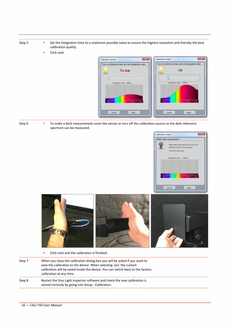
Step 5 ▪ Set the integration time to a maximum possible value to ensure the highest resolution and thereby the best calibration quality.
▪ Click next
Step 6 ▪ To make a dark measurement cover the sensor or turn off the calibration source so the dark reference spectrum can be measured.
▪ Click next and the calibration is finished.
Step 7 When you close the calibration dialog box you will be asked if you want to save the calibration to the device. When selecting ‘yes’ the custom calibration will be saved inside the device. You can switch back to the factory calibration at any time.
Step 8 Restart the Viso Light Inspector software and check the new calibration is stored correctly by going into Setup - Calibration.

At Viso Systems we design, develop and manufacture OEM- and customer-specific
goniophotometer solutions. Our mission is to support customers with powerful and
yet easy to use control measurements solutions. Products are developed and
manufactured in Copenhagen, Denmark.