Embed Size (px)
Citation preview

VSX4 and VSX8 SeriesInstruction ManualD103127X012
VSX4 and VSX8 Series Controller
Table of ContentsIntroduction . . . . . . . . . . . . . . . . . . . . . . . . . . . . . . . . . . . . . 1Specifications . . . . . . . . . . . . . . . . . . . . . . . . . . . . . . . . . . . 2Principle of Operation . . . . . . . . . . . . . . . . . . . . . . . . . . . . . 2Installation . . . . . . . . . . . . . . . . . . . . . . . . . . . . . . . . . . . . . . 4Reed Switch . . . . . . . . . . . . . . . . . . . . . . . . . . . . . . . . . . . . 6Dimensions . . . . . . . . . . . . . . . . . . . . . . . . . . . . . . . . . . . . . 7Startup and Shutdown . . . . . . . . . . . . . . . . . . . . . . . . . . . . . 8Commissioning . . . . . . . . . . . . . . . . . . . . . . . . . . . . . . . . . . 8Controller Spring Adjustment . . . . . . . . . . . . . . . . . . . . . . . . 8Maintenance . . . . . . . . . . . . . . . . . . . . . . . . . . . . . . . . . . . 12Parts Ordering . . . . . . . . . . . . . . . . . . . . . . . . . . . . . . . . . . 13Parts List . . . . . . . . . . . . . . . . . . . . . . . . . . . . . . . . . . . . . . 14
▲ WARNINGFailure to follow these instructions or to properly install and maintain this equipment could result in an explosion and/or fire causing property damage and personal injury or death.Fisher™ controller must be installed, operated and maintained in accordance with federal, state and local codes, rules and regulations and Emerson Process Management Regulator Technologies, Inc. (Emerson) instructions.Only a qualified person must install or service the VSX4 and VSX8 Series controller. If a leak develops or if the controller continually vents gas, service to the unit may be required. Failure to correct trouble could result in a hazardous condition.Installation, operation and maintenance procedures performed by unqualified personnel may result in improper adjustment and unsafe operations which may result in equipment damage or personal injury.The VSX4 and VSX8 Series controller do not activate in response to fire, seismic and lightning events.
IntroductionScope of the ManualThis Instruction Manual provides installation, adjustment, maintenance and parts ordering information for the VSX4 and VSX8 Series controller . Instructions for other equipment used with the controller, such as pressure regulators, can be found in separate instruction manuals .
Figure 1. VSX4 and VSX8 Series Controller
May 2021

VSX4 and VSX8 Series
2
SpecificationsThis section lists the specifications for the VSX4 and VSX8 Series controller . The following information is stamped on the nameplate of VSX4 and VSX8 Series: Type and Class, Maximum Outlet Pressure and Spring Range . Additional operating information is located on the Regulator nameplate .
Available Configurations(2)
Types VSX4L and VSX8L: Low-pressure controller which can be integrated into a regulator; with 10 to 1100 mbar / 0 .15 to 16 psig downstream pressureTypes VSX4H and VSX8H: High-pressure controller which can be integrated into a regulator; with 1100 to 4000 mbar / 16 to 58 psig downstream pressure
Functional ClassA: Min, Min and Max InstallationB: Max Installation Only
ConnectionsController Vent: 1/4 NPTExternal Sensing Line: 1/4 NPT
Maximum Emergency Inlet Pressure (PS)(1)(3)(4)(5)
20 .0 bar / 290 psigMaximum Operating Inlet Pressure (Pumax)(1)(3)(4)(5)
16 .0 bar / 232 psigValve Plug Size
VSX4 Series: 24 mm / 0 .94 in .VSX8 Series: 39 mm / 1 .54 in .
Operating Temperature (TS)(1)
According to PED Standards-20 to 66°C / -4 to 150°FNon-PED: -30 to 66°C / -22 to 150°F(2)
Casing MaterialAluminum
Response Time (ta)< 1 second
Resetting Trip MechanismManually after Fault Rectification
Position IndicatorExtended stem visible in center of reset button
Pressure RegistrationInternal or External
European EN Reference StandardEN 14382
Approximate Shipping Weight1 .4 kg / 3 .1 lbs
Options Wire Seal - The VSX4 and VSX8 Series can be ordered with an optional tamper-proof lock wire to preclude unauthorized access to the adjustment springs .Reed switch - An optional remote notification switch can be installed offering the capability to remotely notify the operator should VSX4 or VSX8 Series shut off occur . Operating Temperature: -40 to 70°C / -40 to 158°FDegree of Protection: IP67Product Marking: CE Ex II 2G Ex mb T6 6bCable Length: 3 m / 118 in .
1 . The pressure/temperature limits in this Instruction Manual or any applicable standard limitation should not be exceeded .2. Product has passed Emerson testing for shutoff and trip function at -40°C/°F.3 . EN334 Integral Strength (IS) 6 bar / 87 psig . Used where inlet rating must equal outlet rating per code . 4. EN334 Differential Strength (DS) 16 bar / 232 psig. Used where DS ratings required per code. 5. EN334 Specific Maximum Allowable Pressure (PSd) 6 bar / 87 psig . Used where PSd ratings are required per code .
Product DescriptionThe VSX4 and VSX8 Series controller are designed to shut off the flow of gas to the downstream system in the event of outlet pressure rising above or falling below the predefined levels.
• The VSX4 and VSX8 Series can be mounted on various Emerson regulators or be used as standalone Type VS100 units .
• The VSX4 and VSX8 Series can be integrated in a slam-shut device Type VS100 installed upstream of the associated regulator .
• The VSX4 and VSX8 Series controller are equipped with an internal bypass .
• The VSX4 and VSX8 Series offer either internal or external pressure sensing line, depending on the regulator type and/or the specified conditions.
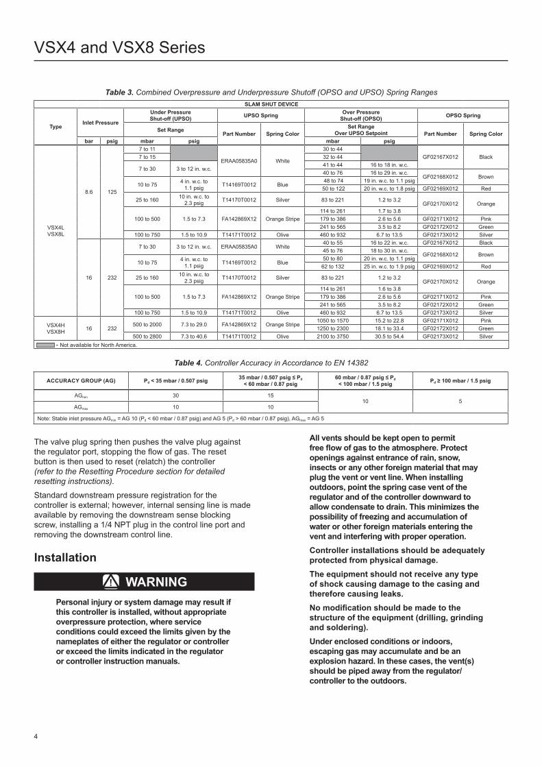
Principle of OperationVSX4 and VSX8 Series ControllerThe pressure measuring element of the controller consists of a diaphragm that senses downstream pressure . The downstream pressure is controlled by the regulator . The overpressure shut-off spring and under-pressure shut-off spring exerts force on the top side of the diaphragm .When the downstream pressure increases above the Overpressure Shutoff (OPSO) setting, the diaphragm moves up .When the downstream pressure decreases below the Underpressure Shutoff (UPSO) setting, the diaphragm moves down .Both of these actions result in the rotation of the cam and the release of the reset pin .

IS DS
A
B
ISDSLPHP
VSX8L VSX8H VSX4L VSX4H
PS Pumax PSD PS Pumax PSD
No de SérieSERIAL No.
TYPE
FRANCEL SASChartres FRANCE
AnYEAR
UtilisationINDENTED USE
2 G T
2 G T
VSX4 and VSX8 Series
3
6 bar16 bar1 .5 bar5 .5 bar
Min, Min and Max installationMax installation only
Pressure range following service condition
6 bar 6 bar 6 bar20 bar 16 bar 6 bar
Figure 2. EN 14382-VSX4/VSX8 Series Label
Figure 3. Nameplate for Explosive Atmosphere if ATEX Assembled
Table 1. Directive ATEX Information
TYPE CLASSIFICATION ATEX ASSEMBLIES ATEX LABELLING
VSX4 VSX8 Non-electrical equipment Not falling under the ATEX Directive 2014/34/EU No
VSX8 with Reed ContactNon-electric equipment equipped with an
electrical device falling under the scope of the ATEX Directive 2014/34/EU
Constitutes an assembly according to the ATEX Directive 2014/34/EU
Table 2. Overpressure Shutoff (OPSO) Only Spring Ranges
SLAM SHUT DEVICE
TypeInlet Pressure Over Pressure Shut-off (OPSO) Set Range OPSO Spring
bar psig mbar psig Part Number Spring Color
VSX4L VSX8L 8 .6 and 16 125 and 232
30 to 60 12 to 24 in . w .c . GF02168X012 Brown
40 to 110 16 in . w .c . to 1 .6 psig GF02169X012 Red
60 to 193 24 in . w .c . to 2 .8 psig GF02170X012 Orange
95 to 280 1 .4 to 4 .1 GF02171X012 Pink
138 to 500 2 .0 to 7 .3 GF02172X012 Green
221 to 760 3 .2 to 11 .0 GF02173X012 Silver
400 to 1450 5 .8 to 21 .0 GF04353X012 Yellow
VSX4H VSX8H 16 232
400 to 1100 5 .8 to 16 .0 GF02171X012 Pink
580 to 2000 8 .4 to 29 .0 GF02172X012 Green
900 to 3000 13 .1 to 43 .5 GF02173X012 Silver
1600 to 5500 23 .2 to 79 .8 GF04353X012 Yellow
VSX4 and VSX8 Series
4
The valve plug spring then pushes the valve plug against the regulator port, stopping the flow of gas . The reset button is then used to reset (relatch) the controller (refer to the Resetting Procedure section for detailed resetting instructions).
Standard downstream pressure registration for the controller is external; however, internal sensing line is made available by removing the downstream sense blocking screw, installing a 1/4 NPT plug in the control line port and removing the downstream control line .
Table 3. Combined Overpressure and Underpressure Shutoff (OPSO and UPSO) Spring RangesSLAM SHUT DEVICE
TypeInlet Pressure
Under Pressure Shut-off (UPSO) UPSO Spring Over Pressure
Shut-off (OPSO) OPSO Spring
Set RangePart Number Spring Color
Set Range Over UPSO Setpoint Part Number Spring Color
bar psig mbar psig mbar psig
VSX4L VSX8L
8 .6 125
7 to 11
ERAA05835A0 White
30 to 44GF02167X012 Black7 to 15 32 to 44
7 to 30 3 to 12 in . w .c .41 to 44 16 to 18 in . w .c .40 to 76 16 to 29 in . w .c .
GF02168X012 Brown10 to 75 4 in . w .c . to
1 .1 psig T14169T0012 Blue 48 to 74 19 in . w .c . to 1 .1 psig 50 to 122 20 in . w .c . to 1 .8 psig GF02169X012 Red
25 to 160 10 in . w .c . to 2 .3 psig T14170T0012 Silver 83 to 221 1 .2 to 3 .2
GF02170X012 Orange
100 to 500 1 .5 to 7 .3 FA142869X12 Orange Stripe114 to 261 1 .7 to 3 .8179 to 386 2 .6 to 5 .6 GF02171X012 Pink241 to 565 3 .5 to 8 .2 GF02172X012 Green
100 to 750 1 .5 to 10 .9 T14171T0012 Olive 460 to 932 6 .7 to 13 .5 GF02173X012 Silver
16 232
7 to 30 3 to 12 in . w .c . ERAA05835A0 White40 to 55 16 to 22 in . w .c . GF02167X012 Black45 to 76 18 to 30 in . w .c .
GF02168X012 Brown10 to 75 4 in . w .c . to
1 .1 psig T14169T0012 Blue50 to 80 20 in . w .c . to 1 .1 psig62 to 132 25 in . w .c . to 1 .9 psig GF02169X012 Red
25 to 160 10 in . w .c . to 2 .3 psig T14170T0012 Silver 83 to 221 1 .2 to 3 .2
GF02170X012 Orange
100 to 500 1 .5 to 7 .3 FA142869X12 Orange Stripe114 to 261 1 .6 to 3 .8179 to 386 2 .6 to 5 .6 GF02171X012 Pink241 to 565 3 .5 to 8 .2 GF02172X012 Green
100 to 750 1 .5 to 10 .9 T14171T0012 Olive 460 to 932 6 .7 to 13 .5 GF02173X012 Silver
VSX4H VSX8H 16 232
500 to 2000 7 .3 to 29 .0 FA142869X12 Orange Stripe1050 to 1570 15 .2 to 22 .8 GF02171X012 Pink1250 to 2300 18 .1 to 33 .4 GF02172X012 Green
500 to 2800 7 .3 to 40 .6 T14171T0012 Olive 2100 to 3750 30 .5 to 54 .4 GF02173X012 Silver - Not available for North America .
Table 4. Controller Accuracy in Accordance to EN 14382
ACCURACY GROUP (AG) Pd < 35 mbar / 0.507 psig 35 mbar / 0.507 psig ≤ Pd < 60 mbar / 0.87 psig
60 mbar / 0.87 psig ≤ Pd < 100 mbar / 1.5 psig Pd ≥ 100 mbar / 1.5 psig
AGmin 30 1510 5
AGmax 10 10
Note: Stable inlet pressure AGmin = AG 10 (Pd < 60 mbar / 0 .87 psig) and AG 5 (Pd > 60 mbar / 0 .87 psig), AGmax = AG 5
Installation
▲ WARNINGPersonal injury or system damage may result if this controller is installed, without appropriate overpressure protection, where service conditions could exceed the limits given by the nameplates of either the regulator or controller or exceed the limits indicated in the regulator or controller instruction manuals.
All vents should be kept open to permit free flow of gas to the atmosphere. Protect openings against entrance of rain, snow, insects or any other foreign material that may plug the vent or vent line. When installing outdoors, point the spring case vent of the regulator and of the controller downward to allow condensate to drain. This minimizes the possibility of freezing and accumulation of water or other foreign materials entering the vent and interfering with proper operation.Controller installations should be adequately protected from physical damage.The equipment should not receive any type of shock causing damage to the casing and therefore causing leaks.No modification should be made to the structure of the equipment (drilling, grinding and soldering).Under enclosed conditions or indoors, escaping gas may accumulate and be an explosion hazard. In these cases, the vent(s) should be piped away from the regulator/controller to the outdoors.
ERAA11922-02
ERAA10261-AA
VSX4 and VSX8 Series
5
UNDERPRESSURE SHUTOFF (UPSO) ADJUSTING SCREW
DIAPHRAGM
DOWNSTREAM SENSE BLOCKING SCREW
VALVE PLUGVALVE PLUG SPRING
RESET PINRESET BUTTON
CAM
OVERPRESSURE SHUTOFF (OPSO) SPRING
UNDERPRESSURE SHUTOFF (UPSO) SPRING
OVERPRESSURE SHUTOFF (OPSO) ADJUSTING SCREW
VSX8 SERIES
UNDERPRESSURE SHUTOFF (UPSO) ADJUSTING SCREW
DIAPHRAGM
DOWNSTREAM SENSE BLOCKING SCREW
VALVE PLUG
VALVE PLUG SPRING
RESET PINRESET BUTTON
CAM
OVERPRESSURE SHUTOFF (OPSO) SPRING
UNDERPRESSURE SHUTOFF (UPSO) SPRING
OVERPRESSURE SHUTOFF (OPSO) ADJUSTING SCREW
VSX4 SERIESINLET PRESSURE, Pu
OUTLET PRESSURE, Pd
ATMOSPHERIC PRESSURE, Pb
Figure 4. VSX4/VSX8 Series Operational Schematics

VSX4 and VSX8 Series
6
Failure to install a downstream control line could result in a hazardous condition. Install downstream control line(s) to the controller when construction uses external pressure registration. The regulator and controller will not control pressure or shut off if a downstream control line is not installed on those constructions where external pressure sensing line is required.If the controller is exposed to an overpressure condition, it should be inspected for any damage that may have occurred. Controller operation within ratings does not preclude the possibility of damage from external sources or from debris in the pipeline.
General Installation Instructions
Note
The VSX4 and VSX8 Series can be rotated 360° for easy installation and maintenance.
Install, use and maintain in accordance to all applicable codes and standards .Before proceeding to installation:• Ensure that the controller is compatible with the gas
being regulated .• Check for damage that might have occurred
during shipment .• Check for and remove any dirt or foreign material that
may have accumulated in the regulator or controller body .• Ensure that the external or internal sense port is clean .• When applying pipe sealing compound to piping and
fittings, always apply to external threads.• Verify that:
- Equipment limits of utilization (PS, TS) correspond to the desired operating conditions .
- The inlet is protected by an appropriate device(s) to avoid exceeding the allowable limits (PS, TS) .
- The controller and its springs correspond to the desired operating conditions of associated regulator .
• Connect downstream control line tubing to the 1/4 NPT connection in the lower casing and to the downstream pipe respecting a minimum distance of four times its diameter (see Figure 6) .
• Periodically check all vent openings to be sure that they are not plugged .
Table 5. Controller Standard Factory SettingsREGULATOR SETPOINT,
mbar / psigCONTROLLER STANDARD SETTINGS
UPSO / Minimum OPSO(1)(2) / Maximum OPSO(3) / MaximumPd < 35 / 0 .51 Pd x 0 .5 Pd x 2 .0 Pd x 2 .0 + 10 mbar / 0 .145 psig
35 / 0 .51 < = Pd < 60 / 0 .87 Pd x 0 .5 Pd x 1 .7 Pd x 1 .7 + 10 mbar / 0 .145 psig60 / 0 .87 < = Pd < 160 / 2 .32 Pd x 0 .6 Pd x 1 .5 Pd x 1 .5 + 10 mbar / 0 .145 psig160 / 2 .32 < = Pd < 180 / 2 .61 Pd x 0 .7 Pd x 1 .4 Pd x 1 .4 + 10 mbar / 0 .145 psig180 / 2 .61 < = Pd < 300 / 4 .35 Pd x 0 .7 Pd x 1 .4
- - - -300 / 4 .35 < = Pd Pd x 0 .7 Pd x 1 .3
The VSX4 Series assembly part number (without valve plug and controller springs): LP: GE35589X012, HP: GE35590X012The VSX8 Series assembly part number (without valve plug and controller springs): LP: ERCA02667A0, HP: ERCA02668A0 1 . Regulator without relief valve (or with relief valve set above controller setting) .2 . When selecting OPSO set points, the outlet pressure rating of the regulator should be considered .3 . Regulator with relief valve (set below controller setting) .
Reed Switch
▲ WARNINGDo not use the manual button if there is no plug. This action may damage the magnet associated with the reed contact if trip the VSX8 Series.
An optional remote notification switch can be installed offering the capability to remotely notify the operator should VSX4 or VSX8 Series shut off occur . Reed switch is available on CSB404/604/704 regulators and VS100 Series stand alone slam-shut .
▲ WARNINGDo not pull, pinch or carry the VSX8 Series by the cable of contact reed. Unsuitable handling of cable can damage the reed contact.
Description and RecommendationsThis electrical contact is a limit switch contact based on the reed contact principle . The actuation takes place through a permanent magnet . The operation of the electrical contact may be affected by magnetic materials . Initial commissioning is done in combination with a signal processing control device . The operator must check the electrical data for the VSX8 Series tripping . The reed contacts must be installed in such a way as to be protected against mechanical hazards as well as prolonged exposure to sunlight . Specific instructions are available in the supplier’s instruction manual .
InstallationThe reed switch option is available on the VSX4 and VSX8 Series slam-shuts mounted in our factory . If the magnet for the reed switch has not been attached at the factory the switch cannot be installed later in the field . The switch or retrofit option must be ordered from the factory .
▲ WARNINGThe usage of an assembly incorporating an electrical accessory in an explosive atmosphere the release relay VSX8 Series equipped with an electrical accessory (proxy, microswitch) is:– is classified “assembly” in conformity
with the ATEX Directive 2014/34/EU (ref CEN/SFG-I Guidance sheet -February 2015)

146 / 5.8
Ø 118 / 4.6
28 / 1.1
147 / 5.8
mm / IN.
Pu PdD
VSX4 and VSX8 Series
7
SPRING REMOVAL CLEARANCE 80 / 3.1
RESET TRIP CLEARANCE: 25 / 1REMOVAL CLEARANCE: 45 / 1.8
Figure 5. Controller External Dimensions
REGULATOR
REGULATOR SENSE LINE
4 x D(MINIMUM)
SLAM-SHUT DEVICESENSE LINE
SLAM-SHUT DEVICE
Figure 6. Typical Installation

VSX4 and VSX8 Series
8
– can be installed in any type of classified zones according to the Directive 1999/92/EC dated 16 December 1999, according to the following conditions:a) the equipment(s) is connected to a
suitable and certified intrinsically safe apparatus/electric circuit (zener barrier)
Additional electrical data for intrinsic safety protection use: the encapsulated protection mode as a single electric device is compatible with use “ia’’ within following conditions:
Pi max: 3W/VA Ui max: 30V AC/DC Ii max: 200 mA C = 0.1 nF/m L = 500 μH/mb) the equipment is used according to
the appropiate instruction manual issued by the manufactuer and/or available on our website
c) when the equipment is used in a natural gas pressure reducing and/or metering station in compliance with the following European standards: EN 12186, EN 12279 and EN 1776.
Startup and Shutdown
△ CAUTIONThis Instruction Manual should be used in conjunction with the instruction manual of the associated equipment.
Commissioning
▲ WARNINGAll interventions on the equipment should only be performed by competent and trained personnel.
Controller Spring Adjustment
▲ WARNINGBefore proceeding with the adjustment of the controller springs, the operator must ensure upstream and downstream valves are closed and adjusting screws (keys 43 and 40, Figure 15) are unscrewed (refer to Table 6).
Overpressure and Underpressure Shutoff (OPSO/UPSO) Setpoint Adjustment (Figures 4 and 15) • Using a flathead screwdriver or 1/4 in. drive socket, turn
the OPSO adjusting screw (key 43) clockwise until it stops turning .
• Apply nominal outlet pressure of the associated regulator to the downstream system . Refer to Figure 6 .
• Reset the controller per the resetting procedure (refer to the Resetting Procedure section for detailed resetting instructions).
• Slowly decrease the downstream pressure to the desired UPSO value (Pdsu) .
• With a screwdriver or 1/4 in . drive socket, turn the UPSO adjusting screw clockwise (key 40) until the controller trips .
• Apply nominal outlet pressure of the associated regulator to the downstream system .
• Reset the controller by pulling the reset button (key 30) until the mechanism is latched .
• Slowly increase the downstream pressure to the desired OPSO shutoff value (Pdso) .
• With a screwdriver or 1/4 in . drive socket, turn the OPSO adjusting screw counterclockwise (key 43) until the controller trips .
Overpressure Shutoff (OPSO) Setpoint Adjustment Only (Figures 4 and 15)• Using a flathead screwdriver or 1/4 in. drive socket, turn
the OPSO adjusting screw (key 43) clockwise until it stops turning .
• Apply nominal outlet pressure of the associated regulator to the downstream system .
• Reset the controller per the resetting procedure, (Refer to the Resetting Procedure section for detailed resetting instructions).
• Slowly increase the downstream pressure to the desired OPSO value (Pdso) .
• Using a flathead screwdriver or 1/4 in. drive socket, turn the OPSO adjusting screw counterclockwise (key 43) until the controller trips .
Manual Shut-off Procedure (Figure 9)Using a screwdriver, press the manual shut-off button (key 23) to manually trip the controller .

26
107
54
52
30
4a4e10596A
106
1
VSX4 and VSX8 Series
9
Figure 7. VSX8 Series with Reed Switch
Figure 8. Installation of Reed Switch
APPLY ADHESIVE(1):1 . Adhesives must be selected such that they meet the temperature requirements .
2347
30
30
26
VSX4 and VSX8 Series
10
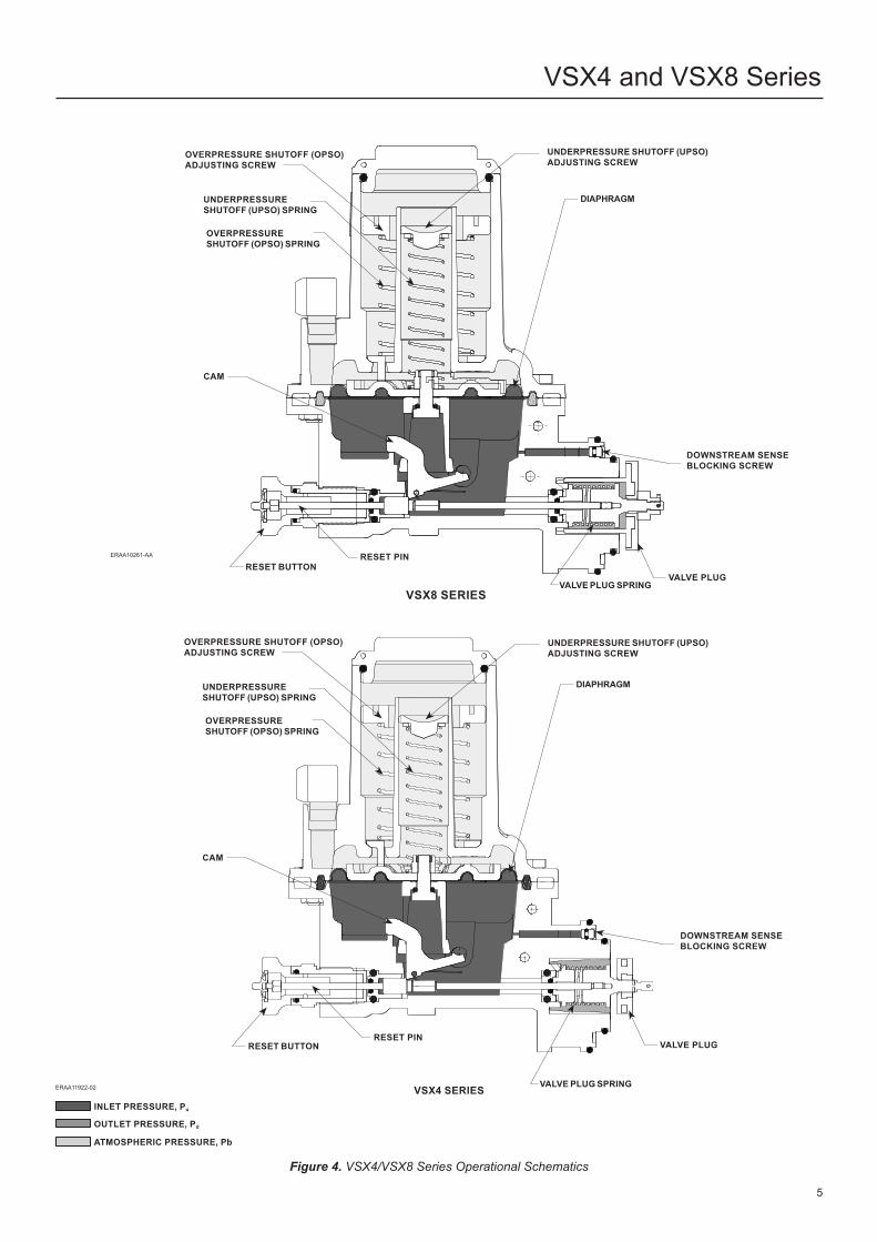
Manual Shut-Off Button Procedure For VSX4 And VSX8 Series
DOWNSTREAM CONTROL LINE CONNECTION
Figure 9. Controller Manual Shut-off Button (key 23) Figure 10. Controller Manual Bypass
Figure 11. Relatching the Controller Mechanism Figure 12. Repositioning the Reset Button
27
VSX4 and VSX8 Series
11
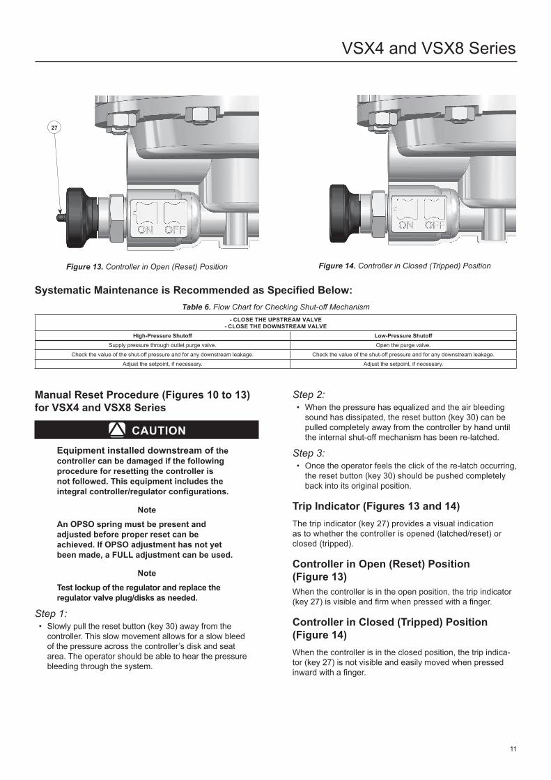
Figure 13. Controller in Open (Reset) Position Figure 14. Controller in Closed (Tripped) Position
Systematic Maintenance is Recommended as Specified Below:Table 6. Flow Chart for Checking Shut-off Mechanism
- CLOSE THE UPSTREAM VALVE- CLOSE THE DOWNSTREAM VALVE
High-Pressure Shutoff Low-Pressure ShutoffSupply pressure through outlet purge valve . Open the purge valve .
Check the value of the shut-off pressure and for any downstream leakage. Check the value of the shut-off pressure and for any downstream leakage.Adjust the setpoint, if necessary . Adjust the setpoint, if necessary .
Manual Reset Procedure (Figures 10 to 13) for VSX4 and VSX8 Series
△ CAUTIONEquipment installed downstream of the controller can be damaged if the following procedure for resetting the controller is not followed. This equipment includes the integral controller/regulator configurations.
NoteAn OPSO spring must be present and adjusted before proper reset can be achieved. If OPSO adjustment has not yet been made, a FULL adjustment can be used.
NoteTest lockup of the regulator and replace the regulator valve plug/disks as needed.
Step 1:• Slowly pull the reset button (key 30) away from the
controller . This slow movement allows for a slow bleed of the pressure across the controller’s disk and seat area . The operator should be able to hear the pressure bleeding through the system .
Step 2:• When the pressure has equalized and the air bleeding
sound has dissipated, the reset button (key 30) can be pulled completely away from the controller by hand until the internal shut-off mechanism has been re-latched.
Step 3:• Once the operator feels the click of the re-latch occurring,
the reset button (key 30) should be pushed completely back into its original position .
Trip Indicator (Figures 13 and 14)The trip indicator (key 27) provides a visual indication as to whether the controller is opened (latched/reset) or closed (tripped) .
Controller in Open (Reset) Position (Figure 13)When the controller is in the open position, the trip indicator (key 27) is visible and firm when pressed with a finger.
Controller in Closed (Tripped) Position (Figure 14)When the controller is in the closed position, the trip indica-tor (key 27) is not visible and easily moved when pressed inward with a finger.

VSX4 and VSX8 Series
12
Maintenance
▲ WARNINGOnly a competent and qualified person may perform maintenance procedures. If necessary, contact your local Sales Office for assistance.Failure to test the controller for proper shutoff can result in a hazardous condition. Test the controller for operation per applicable federal, state and local codes, rules and regulations and Emerson instructions.Due to normal wear or damage that may occur from external sources, the controller should be inspected and maintained periodically. The frequency of inspection and replacement depends on the severity of service conditions and on applicable codes and regulations. In accordance with applicable National or Industry codes, standards and regulations/recommendations, all hazards covered by specific tests after final assembly before applying the CE marking, shall also be covered after every subsequent reassembly at installation site, in order to ensure that the equipment will be safe throughout its intended life.Periodic inspection must be performed on the VSX4 and VSX8 Series. The controller should be tested for both under and overpressure shutoff activation and pressure tight shutoff annually with test intervals not to exceed 15 months but at least once each calendar year. If the controller does not close at the desired pressures or leaks gas after closure, repair and/or replace the controller. For the verification of internal parts and replacement of worn parts, the controller should be disassembled every 3 years minimum.
Disassembly and ReassemblyNote
User should only disassemble the controller to replace the Valve Plug (Disk), change registration from Internal to External and Spring and Diaphragm Replacement as described below.
All other internal disassembly requires special tooling and should be done only at the factory; for example the cam and reset pin assembly (key 4, Figure 15).
▲ WARNINGOnly parts manufactured by Emerson should be used for repairing the VSX4 and VSX8 Series Slam-shut Device.
Valve Plug (Disk) Replacement
▲ WARNINGTo avoid personal injury or equipment damage, do not attempt any maintenance or disassembly without first isolating the regulator/controller from system pressure and relieving all internal pressure.Installation of an incorrect size valve plug (disk) will prevent the controller from shutting off the flow of gas in an overpressure or under pressure scenario resulting in a hazardous condition. A 39 mm / 1.54 in. diameter valve plug must be installed in VSX8 Series controllers for proper operation. VSX4 Series controllers require the use of the 24 mm / 0.94 in. diameter valve plug.
• Refer to Figure 15 when following this procedure . Remove the body flange screws (key 34) and the two half flanges (key 36) . Remove the controller from the body .
• For VSX4 Series disk replacement, remove the fastening ring (key 44) . For VSX8 Series disk replacement, remove the travel stop/cotter pin (key 53) and the safety nut (key 58) . For specific tools needed for this step, see Table 7.
• Remove and replace the valve plug (disk) (key 47) .• Replace the fastening ring (key 44) or safety nut (key 58)
and cotter pin (key 53) . To replace the safety nut (key 58) screw the nut onto the plug support until it stops and then reverse the nut until the cotter pin (key 53) can be assembled .
• Reassemble in reverse order, taking care to follow the steps outlined in the General Controller Reassembly Procedures section .
• Test the controller for proper operation at the desired OPSO and/or UPSO set points . Readjust set point(s) if needed .
Changing from Internal to External Registration
▲ WARNINGTo avoid personal injury or equipment damage, do not attempt any maintenance or disassembly without first isolating the regulator/controller from system pressure and relieving all internal pressure.
• Refer to Figure 15 when following this procedure . Remove the body flange screws (key 34) and the two half flanges (key 36) . Remove the controller from the body .
• Install the sense blocking screw (key 51) and O- ring (key 50) .
• Remove the 1/4 NPT plug from the 1/4 NPT Control line port (Figure 6) .
• Reassemble in reverse order, ensure to follow the steps outlined in the General Controller Reassembly Procedures section .

TOOL USAGEFlathead screwdriver and 1/4 in . drive • Adjustment of Overpressure and Underpressure Shutoff (OPSO / UPSO) setting
10 mm / 3/8 in . Wrench• Removal and installation of the actuator screws (key 16, Figure 15)• Removal and installation of body flange screws (key 34, Figure 15)• Removal and installation of the lock nut (key 31, Figure 15)
14 mm / 9/16 in . Wrench • Removal and installation of the external sense line 1/4 NPT connection (Figure 6)Internal retaining ring pliers • Removal and installation of the VSX4 Series fastening ring (key 44, Figure 15)
Needle Nose Pliers • Removal and installation of Cotter Pin for VSX8 Series
Table 7. Recommended Tools
INDICATION CAUSE ACTION
If the valve will not close Operating fault
Check the following:• The shut-off pressure settings for high and low pressure values are correct.• The O-rings are sealing tightly .• The sensing line is plugged .Remove the controller and check the following:• The reset latch is not stuck .• The state of the diaphragm assembly for wear and tear .Or contact your local Sales Office.
If the downstream pressure in the controller decreases External leak Locate and seal the leak .Or contact your local Sales Office.
If the outlet pressure in the controller is constant - - - - • Bleed off the outlet side of the regulator.• Observe the evolution of the outlet pressure (check tightness) .
If the downstream pressure in the controller increases Internal leak
Check the following: • The valve plug (disk)• The internal interface O-ring (key 46, Figure 15)• The reset stem O-ring (key 29, Figure 15)Or contact your local Sales Office.
Table 8. VSX4 and VSX8 Series Troubleshooting
VSX4 and VSX8 Series
13
• Connect a downstream control line with an outer diameter of 6 .4 mm / 0 .25 in . or larger to the 1/4 NPT Control line port shown in Figure 6 and to the downstream system as indicated in Figure 6 .
Spring and Diaphragm Replacement• Refer to Figure 15 when following this procedure .
Unscrew and remove the closing cap (key 3) . Using a flathead screwdriver, unscrew and remove the OPSO adjusting screw (key 43), OPSO spring (key 41), maximum washer (key 42) .
• Unscrew and remove the UPSO adjusting screw (key 40), mini washer (key 103) and UPSO spring (key 38) .
• Using a 10 mm / 3/8 in . wrench, unscrew and remove the eight spring case screws (key 16) and associated nuts (key 12) and then remove the spring case (key 2) . For Type VSX4H or VSX8H, remove the diaphragm support (key 32) .
• To remove the diaphragm assembly, gently grasp the edge of the diaphragm (key 6) while at the same time pulling the reset button (key 30) slightly, which will allow for sliding the back plate (key 5) off of the cam (key 19).
Grasp the back plate (key 5) and unscrew the nut (key 31) using a 10 mm / 3/8 in . wrench . Remove the diaphragm plate (key 7) and inspect the diaphragm and replace if necessary . The lock nut (key 31) should always be replaced .
Reassemble in reverse order, ensure to follow steps outlined in the following section “General Controller Reassembly Procedures .” Note that when tightening the lock nut (key 31) onto screw (key 16), a hexagonal recess exists at the bottom of the back plate (key 5) that precludes the screw (key 16) from turning to allow the lock nut (key 31) to be threaded .
General Controller Reassembly Procedures• It is recommended that O-rings (keys 14 and 24) be
replaced before reinstalling the controller valve onto the regulator body .
• Before reassembly, inspect removed O-rings for damage or wear and replace if necessary .
• Before reassembly, apply silicone grease lubricant to the appropriate O-rings .
• Using graphite molybdenum, grease appropriate screws, setting nuts and springs (keys 38, 40, 41, 43 and 103) .
• Recommended torque for screws (key 16) is 6 .0 N•m / 4 .4 ft-lbs .
• Recommended torque for lock nut (key 31) is 3 N•m / 27 in-lbs .
• Recommended torque for the body flange screws (key 34) is 6 N•m / 4 .4 ft-lbs .
Parts OrderingController that have been disassembled for repair must be tested for proper operation before being returned to service .The type number, pressure ranges, functional class and date of manufacture are stamped on the nameplate . Always provide this information when corresponding with your local Sales Office regarding replacement parts or technical assistance .
When ordering replacement parts, refer to the key number of each needed part as found in the parts list .Separate kits containing all recommended spare parts are available . See tables on pages 14 and 16 .
VSX4 and VSX8 Series
14
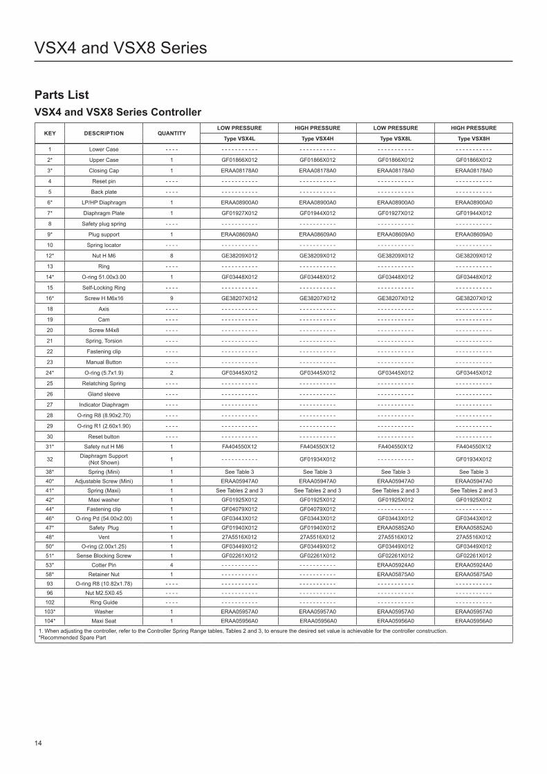
Parts ListVSX4 and VSX8 Series Controller
KEY DESCRIPTION QUANTITYLOW PRESSURE HIGH PRESSURE LOW PRESSURE HIGH PRESSURE
Type VSX4L Type VSX4H Type VSX8L Type VSX8H
1 Lower Case - - - - - - - - - - - - - - - - - - - - - - - - - - - - - - - - - - - - - - - - - - - - - - - -
2* Upper Case 1 GF01866X012 GF01866X012 GF01866X012 GF01866X012
3* Closing Cap 1 ERAA08178A0 ERAA08178A0 ERAA08178A0 ERAA08178A0
4 Reset pin - - - - - - - - - - - - - - - - - - - - - - - - - - - - - - - - - - - - - - - - - - - - - - - -
5 Back plate - - - - - - - - - - - - - - - - - - - - - - - - - - - - - - - - - - - - - - - - - - - - - - - -
6* LP/HP Diaphragm 1 ERAA08900A0 ERAA08900A0 ERAA08900A0 ERAA08900A0
7* Diaphragm Plate 1 GF01927X012 GF01944X012 GF01927X012 GF01944X012
8 Safety plug spring - - - - - - - - - - - - - - - - - - - - - - - - - - - - - - - - - - - - - - - - - - - - - - - -
9* Plug support 1 ERAA08609A0 ERAA08609A0 ERAA08609A0 ERAA08609A0
10 Spring locator - - - - - - - - - - - - - - - - - - - - - - - - - - - - - - - - - - - - - - - - - - - - - - - -
12* Nut H M6 8 GE38209X012 GE38209X012 GE38209X012 GE38209X012
13 Ring - - - - - - - - - - - - - - - - - - - - - - - - - - - - - - - - - - - - - - - - - - - - - - - -
14* O-ring 51 .00x3 .00 1 GF03448X012 GF03448X012 GF03448X012 GF03448X012
15 Self-Locking Ring - - - - - - - - - - - - - - - - - - - - - - - - - - - - - - - - - - - - - - - - - - - - - - - -
16* Screw H M6x16 9 GE38207X012 GE38207X012 GE38207X012 GE38207X012
18 Axis - - - - - - - - - - - - - - - - - - - - - - - - - - - - - - - - - - - - - - - - - - - - - - - -
19 Cam - - - - - - - - - - - - - - - - - - - - - - - - - - - - - - - - - - - - - - - - - - - - - - - -
20 Screw M4x8 - - - - - - - - - - - - - - - - - - - - - - - - - - - - - - - - - - - - - - - - - - - - - - - -
21 Spring, Torsion - - - - - - - - - - - - - - - - - - - - - - - - - - - - - - - - - - - - - - - - - - - - - - - -
22 Fastening clip - - - - - - - - - - - - - - - - - - - - - - - - - - - - - - - - - - - - - - - - - - - - - - - -
23 Manual Button - - - - - - - - - - - - - - - - - - - - - - - - - - - - - - - - - - - - - - - - - - - - - - - -
24* O-ring (5 .7x1 .9) 2 GF03445X012 GF03445X012 GF03445X012 GF03445X012
25 Relatching Spring - - - - - - - - - - - - - - - - - - - - - - - - - - - - - - - - - - - - - - - - - - - - - - - -
26 Gland sleeve - - - - - - - - - - - - - - - - - - - - - - - - - - - - - - - - - - - - - - - - - - - - - - - -
27 Indicator Diaphragm - - - - - - - - - - - - - - - - - - - - - - - - - - - - - - - - - - - - - - - - - - - - - - - -
28 O-ring R8 (8 .90x2 .70) - - - - - - - - - - - - - - - - - - - - - - - - - - - - - - - - - - - - - - - - - - - - - - - -
29 O-ring R1 (2 .60x1 .90) - - - - - - - - - - - - - - - - - - - - - - - - - - - - - - - - - - - - - - - - - - - - - - - -
30 Reset button - - - - - - - - - - - - - - - - - - - - - - - - - - - - - - - - - - - - - - - - - - - - - - - -
31* Safety nut H M6 1 FA404550X12 FA404550X12 FA404550X12 FA404550X12
32 Diaphragm Support (Not Shown) 1 - - - - - - - - - - - GF01934X012 - - - - - - - - - - - GF01934X012
38* Spring (Mini) 1 See Table 3 See Table 3 See Table 3 See Table 340* Adjustable Screw (Mini) 1 ERAA05947A0 ERAA05947A0 ERAA05947A0 ERAA05947A041* Spring (Maxi) 1 See Tables 2 and 3 See Tables 2 and 3 See Tables 2 and 3 See Tables 2 and 342* Maxi washer 1 GF01925X012 GF01925X012 GF01925X012 GF01925X01244* Fastening clip 1 GF04079X012 GF04079X012 - - - - - - - - - - - - - - - - - - - - - -46* O-ring Pd (54 .00x2 .00) 1 GF03443X012 GF03443X012 GF03443X012 GF03443X01247* Safety Plug 1 GF01940X012 GF01940X012 ERAA05852A0 ERAA05852A048* Vent 1 27A5516X012 27A5516X012 27A5516X012 27A5516X01250* O-ring (2 .00x1 .25) 1 GF03449X012 GF03449X012 GF03449X012 GF03449X01251* Sense Blocking Screw 1 GF02261X012 GF02261X012 GF02261X012 GF02261X01253* Cotter Pin 4 - - - - - - - - - - - - - - - - - - - - - - ERAA05924A0 ERAA05924A058* Retainer Nut 1 - - - - - - - - - - - - - - - - - - - - - - ERAA05875A0 ERAA05875A093 O-ring R8 (10 .82x1 .78) - - - - - - - - - - - - - - - - - - - - - - - - - - - - - - - - - - - - - - - - - - - - - - - -96 Nut M2 .5X0 .45 - - - - - - - - - - - - - - - - - - - - - - - - - - - - - - - - - - - - - - - - - - - - - - - -102 Ring Guide - - - - - - - - - - - - - - - - - - - - - - - - - - - - - - - - - - - - - - - - - - - - - - - -103* Washer 1 ERAA05957A0 ERAA05957A0 ERAA05957A0 ERAA05957A0104* Maxi Seat 1 ERAA05956A0 ERAA05956A0 ERAA05956A0 ERAA05956A0
1 . When adjusting the controller, refer to the Controller Spring Range tables, Tables 2 and 3, to ensure the desired set value is achievable for the controller construction .*Recommended Spare Part

3 14
16
31
5
16
21
51
15
53
10
19
2
24
9
58
47
133
40
80
38
41
104
102
48
42
7
6
12
29
27
96
30 93 26 18 1328
28 29 846
4
103
L2
L2
L2
43
L1 L1
L1
L1
50
L1
L2 3
14
80
84
48
104
42
7
6
12
102
28
29
27
26 18 4 13 28 29 46 8
33
1
47
58
53
9
10
15
51
50
21
19
16
5
24
31
16
2
43
40
103
41
38
L2
L2 L2 L2
L2
L1
L1
L1
L1 L1 L1 L1
L1
L1
L2
L2
L2
A
30
96A
93
L123
24
25
22
20
21 13 81
28 29
47
44
9
10
15
ERCA02667
VSX4 and VSX8 Series
15
Figure 15. Controller Assembly
TORQUE: 1 TO 3 N•m / 9 TO 26 IN-LBS
TORQUE: 3 N•m / 27 IN-LBS
TORQUE: 5.7 TO 6.2 N•m / 50 TO 55 IN-LBS
TORQUE: 0.3 TO 0.55 N•m / 2.7 TO 4.8 IN-LBS
TORQUE: 0.3 TO 0.55 N•m / 2.7 TO 4.9 IN-LBS
VSX8 SERIES
MANUAL BUTTONVSX4 SERIES
APPLY LUBRICANT(1):L1 = MULTI-PURPOSE PTFE LUBRICANT L2 = ANTI-SEIZE LUBRICANT
1 . Lubricants must be selected such that they meet the temperature requirements .

VSX4 and VSX8 Series
Facebook .com/EmersonAutomationSolutions
LinkedIn .com/company/emerson-automation-solutions
Twitter .com/emr_automation
Webadmin .Regulators@emerson .com
Emerson Automation Solutions
The distinctive swirl pattern cast into every actuator casing uniquely identifies the regulator as part of the Fisher™ brand Commercial Service Regulator family and assures you of the highest-quality engineering, performance, and support traditionally associated with Fisher™ and Tartarini™ regulators. Visit www .fishercommercialservice .com to access interactive applications .
Fisher .com
Americas McKinney, Texas 75070 USA T +1 800 558 5853
+1 972 548 3574
Europe Bologna 40013, Italy T +39 051 419 0611
Asia Pacific Singapore 128461, Singapore T +65 6777 8211
Middle East and Africa Dubai, United Arab Emirates T +971 4 811 8100
Parts List (continued)VSX4 AND VSX8 SERIES KIT
Key Quantity Code DescriptionPart Number
Type VSX4L/VSX8L Type VSX4H/VSX8HModification Kit to Change from Internal to External Sense
50 1197898
Sense blocking O-ring (2 .00 x 1 .25) (for external only) GF03449X01251 1 Sense blocking screw (for external only) GF02261X012
Diaphragm Replacement Kit6 1
197899Diaphragm GF01929X012
31 1 Lock nut FA404550X12Modification Kit to Change from Low Pressure to High Pressure Construction
7 1
197900
Diaphragm plate - - - - - - - - - - - GF01944X01232 1 Diaphragm support - - - - - - - - - - - GF01934X01214 1 Closing cap O-ring GF03448X01231 1 Lock nut FA404550X12
+ spring according to setpoint -- not included in the kit
Modification Kit to Change from High Pressure to Low Pressure Construction7 1
197901Diaphragm plate GF01927X012 - - - - - - - - - - -
14 1 Closing cap O-ring GF03448X01231 1 Lock nut FA404550X12
+ spring according to setpoint -- not included in the kit
VSX4 Series Repair Kit6 1
RVSX4MCX012
Diaphragm GF01929X01214 1 Closing cap O-ring GF03448X01224 1 Diaphragm Assembly O-ring GF03445X01231 1 Lock nut FA404550X1233 1 Inlet O-ring GF03442X01246 1 Outlet O-ring GF03443X01247 1 Medium Capacity Disk GF01940X012
VSX8 Series Repair Kit6 1
RVSX8X00012
Diaphragm GF01929X01214 1 Closing cap O-ring GF03448X01224 1 Diaphragm Assembly O-ring GF03445X01231 1 Lock nut FA404550X1233 1 Inlet O-ring GF03442X01246 1 Outlet O-ring GF03443X01247 1 High Capacity Disk ERAA05852A053 1 Cotter Pin ERAA05924A0
Retrofit Switch Kit
- - - - 1 RVSX Reed switch PN
Reed switch retrofit kit (Only usable on VSX with magnet already installed at the Factory) - - - - - - - - - - -
D103127X012 © 2009, 2021 Emerson Process Management Regulator Technologies, Inc . All rights reserved . 05/21 . The Emerson logo is a trademark and service mark of Emerson Electric Co . All other marks are the property of their prospective owners . Fisher™ is a mark owned by Fisher Controls International LLC, a business of Emerson Automation Solutions .
The contents of this publication are presented for informational purposes only, and while every effort has been made to ensure their accuracy, they are not to be construed as warranties or guarantees, express or implied, regarding the products or services described herein or their use or applicability . All sales are governed by our terms and conditions, which are available upon request . We reserve the right to modify or improve the designs or specifications of such products at any time without notice .
Emerson Process Management Regulator Technologies, Inc does not assume responsibility for the selection, use or maintenance of any product . Responsibility for proper selection, use and maintenance of any Emerson Process Management Regulator Technologies, Inc . product remains solely with the purchaser .