Embed Size (px)
Citation preview
SOUND LEVEL METER
INSTRUCTION MANUAL
2
1. SAFETY INFORMATION
Read the following safety information carefully before
attempting to operate or service the meter.
Use the meter only as specified in this manual:
Environment conditions
① Altitude lower than 2000 meters
② Relatively humidity ≤90%RH
③ Operation Ambient 0 ~ 40°C
Maintenance & Clearing
① Repair or servicing not covered in this manual
should be performed by qualified personnel.
② Periodically wipe the case with a dry cloth. Do not
use solvents or eradicator on this instrument.
Safety symbols
Comply with EMC
2. FUNCTIONS DESCRIPTION
This Sound Level Meter is designed for noise project;
quality control; illness prevention and cure and all kinds of
environmental sounds measurement. It is applied to the
sounds measurement at factory; school; office; traffic
access and household, etc.
This unit confirms to the IEC61672-1 CLASS2 for
Sound Level Meters.
MAX & MIN measurements
Over range display
3
Under range display
A & C Weighting
FAST & SLOW response
Analog AC/DC outputs for connection to frequency
analyzer or X-Y shaft recorder
3. SPECIFICATION
Standard applied: IEC61672 -1 CLASS2
Accuracy:±1.4dB
Frequency range:31.5HZ ~ 8KHZ
Dynamic range:50dB
Memory:32700
Level ranges: LO:30dB~80dB
Med:50dB~100dB
Hi:80dB~130dB
Auto:30dB~130dB
Frequency weighting: A/C
Time weighting: FAST ( 125ms ), SLOW ( 1s )
Microphone: 1/2 inch electret condenser microphone
Display: 4 digits LCD display with a resolution of 0.1dB
Display Update: 2 times/sec.
MAX hold: Hold the Maximum reading
MIN hold: Hold the Minimum reading
HOLD: Hold the readings
Alarm function: “OVER”is when input is more than upper
limit of range.“UNDER”is when input is
less than lower limit of range.
Analog output: AC/DC outputs from earphone outlet
AC=1Vrms ,DC=10mV/dB
4
Data output: USB data traffic
Auto power off:Meter automatically shuts down after
approx. 15 minutes of inactivity.
Power supply: One 9V battery, 006P or NEDA1604 or
IEC 6F22.
Power life: About 30hours
Operation temperature and humidity:
0°C~40°C,10%RH~90%RH
Storage temperature and temperature:
-10°C ~+60°C,10%RH~75%RH
Dimension: 278 (L) x 76 (W) x 50(H) mm
Weight : 350g
Accessories : Instruction manual, battery, screwdriver,
¢3.5mm earphone plug, windscreen,
software, USB cable.
5
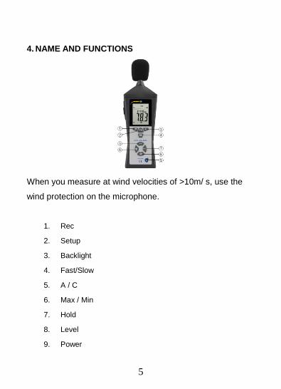
4. NAME AND FUNCTIONS
When you measure at wind velocities of >10m/ s, use the
wind protection on the microphone.
1. Rec
2. Setup
3. Backlight
4. Fast/Slow
5. A / C
6. Max / Min
7. Hold
8. Level
9. Power
6
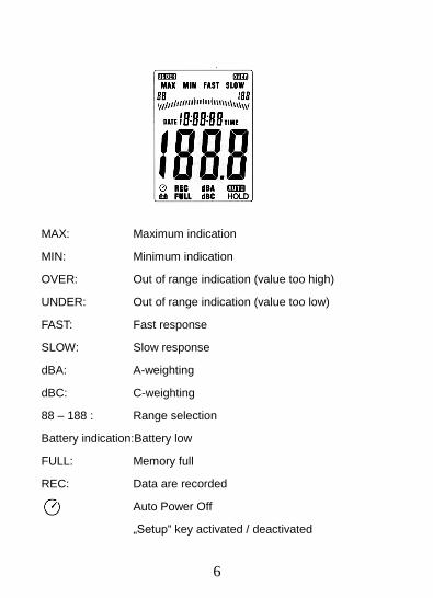
MAX: Maximum indication
MIN: Minimum indication
OVER: Out of range indication (value too high)
UNDER: Out of range indication (value too low)
FAST: Fast response
SLOW: Slow response
dBA: A-weighting
dBC: C-weighting
88 – 188 : Range selection
Battery indication:Battery low
FULL: Memory full
REC: Data are recorded
Auto Power Off
„Setup“ key activated / deactivated
7
„REC“ button
DATALOGGER function
Press “REC” button after it power on, the display will show
“REC” to start Data Recording,press the button again to exit
the record (Note: In order to avoid data error, please don’t
power it off under REC condition, when the REC function is
deleted then it can power off).
Adjusting DATALOGGER response
Press the button continuously before power it on,then
press ,it will be displayed as following: Press ’LEVEL’
button to adjust memory time,press ‘HOLD’ button to hold
the setup;
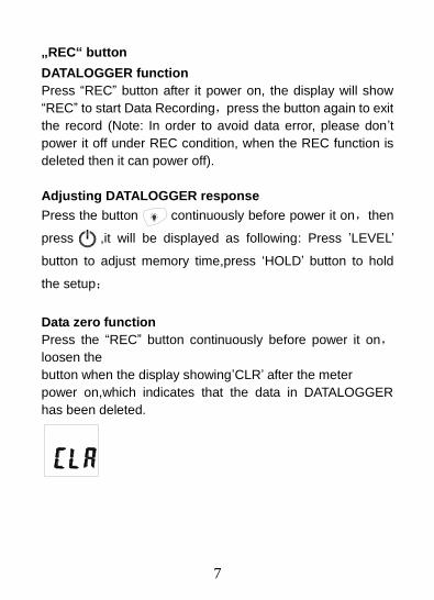
Data zero function
Press the “REC” button continuously before power it on,
loosen the
button when the display showing’CLR’ after the meter
power on,which indicates that the data in DATALOGGER
has been deleted.
8
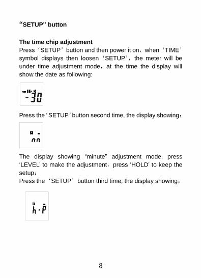
“SETUP” button
The time chip adjustment
Press‘SETUP’button and then power it on,when‘TIME’
symbol displays then loosen‘SETUP’,the meter will be
under time adjustment mode,at the time the display will
show the date as following:
Press the‘SETUP’button second time, the display showing:
The display showing “minute” adjustment mode, press
‘LEVEL’ to make the adjustment,press ‘HOLD’ to keep the
setup;
Press the‘SETUP’button third time, the display showing:
9
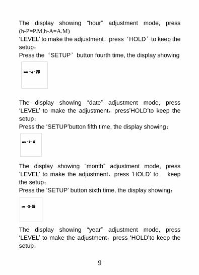
The display showing “hour” adjustment mode, press
(h-P=P.M,h-A=A.M)
‘LEVEL’ to make the adjustment,press‘HOLD’to keep the
setup;
Press the‘SETUP’button fourth time, the display showing
The display showing “date” adjustment mode, press ‘LEVEL’ to make the adjustment,press’HOLD’to keep the
setup;
Press the ‘SETUP’button fifth time, the display showing:
The display showing “month” adjustment mode, press
‘LEVEL’ to make the adjustment,press ‘HOLD’ to keep
the setup;
Press the ‘SETUP’ button sixth time, the display showing:
The display showing “year” adjustment mode, press
‘LEVEL’ to make the adjustment,press ‘HOLD’to keep the
setup;
10
Press the ’SETUP’ button seventh time, the display showing:
The display showing initialization of the time chip,press
‘HOLD’ to keep the setup;time and date have returned to
factory setup. When the battery is exhausted or replaced, if
the time can’t be adjusted then please initialize the time chip
first.
USB communications setting:
Turn on the meter, connect the meter with the computer
correctly, choose the software COM3(COM4),hen press
‘ETUP’ , ‘ ‘ disappears from the display to indicate and
disable auto power off, that the USB data is transmitting.
“FAST/SLOW” button:
Time weighting selection
FAST: st sampling measurement, 1 time per 125mS.
SLOW:Slow sampling measurement, 1 time per second.
11
“MAX/MIN” button:
Maximum and Minimum hold Press this button for one time
to enter MAX/MIN measurement, ‘MAX’ will appear on LCD,
maximum sound level will be captured and held until higher
sound level is captured. Press the button again, ‘MIN’ will
appear on LCD and minimum sound level will be captured
and held until new lower sound level is captured. Press the
button one more time to exit MAX/MIN measurement.
“LEVEL” button: Level range selection
Each time you press “LEVEL” button, the level range will
change between ‘Lo’ level, ‘Med’ level, ‘Hi’ level and ‘Auto’
level in the circular.
Backlight button
8.0.Turn the backlight on/off
8.1.DATALOGGER response setting;
press the button continuously until‘INT’symbol appears
after the meter turn on, press‘LEVEL’to set up the data
memory response, then press‘HOLD’to keep the setting.
12
“A/C” Frequency weighting select button
A:A-Weighting
C:C-Weighting
“HOLD” button:
Press “HOLD” button, The hold function freezes the
reading in the display.
Power button
Turn the meter power ON/OFF
External DC 9V power supply terminal
For connection with DC 9V power supply.
Aperture size: external diameter: 3.5mm, internal
diameter: 1.35mm
USB interface
USB signal output is a 9600 bps serial interface.
13
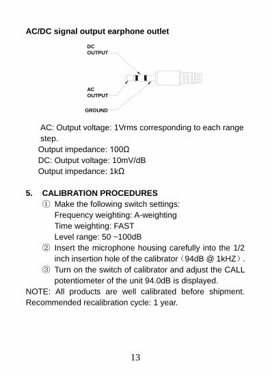
AC/DC signal output earphone outlet
OUTPUT
GROUND
OUTPUT
AC
DC
AC: Output voltage: 1Vrms corresponding to each range
step.
Output impedance: 100Ω
DC: Output voltage: 10mV/dB
Output impedance: 1kΩ
5. CALIBRATION PROCEDURES
① Make the following switch settings:
Frequency weighting: A-weighting
Time weighting: FAST
Level range: 50 ~100dB
② Insert the microphone housing carefully into the 1/2
inch insertion hole of the calibrator(94dB @ 1kHZ).
③ Turn on the switch of calibrator and adjust the CALL
potentiometer of the unit 94.0dB is displayed.
NOTE: All products are well calibrated before shipment.
Recommended recalibration cycle: 1 year.
14
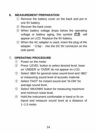
6. MEASUREMENT PREPARATION
① Remove the battery cover on the back and put in
one 9V battery.
② Recover the back cover.
③ When battery voltage drops below the operating
voltage or battery aging, this symbol will
appear on LCD. Replace the 9V battery.
④ When the AC adapter is used, insert the plug of the
adapter (3.5φ) into the DC 9V connector on the
side panel.
7. OPERATING PROCEDURE
① Power on the meter.
② Press ‘LEVEL’ button to select desired level, base
on ‘UNDER’ or ‘OVER’ do not appear on LCD.
③ Select ‘dBA’ for general noise sound level and ‘dBC’
or measuring sound level of acoustic material.
④ Select ‘FAST’ for instant sound and ‘SLOW’ for
average sound level.
⑤ Select ‘MAX/MIN’ button for measuring maximum
and minimum noise level.
⑥ Hold the instrument comfortable in hand or fix on
tripod and measure sound level at a distance of
1~1.5 meter.
15
8. NOTICE
i. Do not store or operate the instrument at high
temperature and high humidity environment.
ii. When not in use for long time, please take out the
battery to avoid battery liquid leakage and cautery
on the instrument.
iii. When using the instrument in the presence of wind,
it is a must to mount the windscreen to not pick up
undesirable signals.
iv. Keep microphone dry and avoid severe vibration.
9. Accessories:
1 x sound level meter PCE-322A
1 x wind protection
1 x screwdriver
1 x mains adaptor
1 x 90 V battery
1 x evaluation software
1 x USB cable
1 x mini tripod
1 x carrying case
1 x user manual
16
10. Installing the software
1. Start windows
2. Insert the CD into the CD-drive.
3. Run SETUP.EXE installation program in file DISK1,
install it to the referred directory
4. Install CP210X drive software:
Connecting the meter with the computer by USB
interface, install CP2102 drive software in my computer
property:\hardware\facility management\ COM
CP210X USB.
USB Drive Installation
1. Copy the CP210XWIN Drivers to a certain directory,
such as: C:\ usb_driver.
2.Connect the USB to the computer, the Windows
system will show finding a new hardware. Choose
specific directory C:\ usb_driver according to the
instruction.
3. After Driver installation, a new COM port will be
added to the Ports in the Device Manager. Port
number will be ranged following the primary COM
ports, such as: COM3 or COM4.
5. Once the drive software is installed, start the application
software, connect the meter to the computer by USB,
then search for the COMX port occupied by CP210X,
press button, the ‘ ‘
symbol will not appear on the display,which indicate
the meter is transmitting data to the computer.
6. Enter the menu REAL TIME \‘SETUP’to set the
17
monitoring data (data volume, response, monitoring
time)
7. DATALOGGER menu:
The computer read the memory data in the meter when
REC not appear on the display and the connection is in
order.
Warranty
18
11. Warranty
You can read our warranty terms in our General Business
Terms which you can find here:
https://www.pce-instruments.com/english/terms.
Disposal
12. Disposal
For the disposal of batteries in the EU, the 2006/66/EC
directive of the European Parliament applies. Due to the
contained pollutants, batteries must not be disposed of as
household waste. They must be given to collection points
designed for that purpose.
In order to comply with the EU directive 2012/19/EU we take
our devices back. We either re-use them or give them to a
recycling company which disposes of the devices in line with
law.
For countries outside the EU, batteries and devices should
be disposed of in accordance with your local waste
regulations.
If you have any questions, please contact PCE Instruments.

![LED Display Wall - Mitsubishi Electric · LED Display Wall [78 Series Version] Display Wall ... Lamp light source range LED light source range ... 1 4 1 2 3 4 1 A "Smart Switch](https://img.pdfslide.us/doc/110x75/5caee0f388c99332318d9f9d/led-display-wall-mitsubishi-led-display-wall-78-series-version-display-wall.jpg)