Embed Size (px)
Citation preview

Reference Manual00809-0200-4702, Rev EA
June 2018
Rosemount™ 702 Wireless Discrete Transmitter


Reference Manual 00809-0200-4702, Rev EA
ContentsJune 2018
Contents
1Section 1: Introduction1.1 Using this manual . . . . . . . . . . . . . . . . . . . . . . . . . . . . . . . . . . . . . . . . . . . . . . . . . . . . . . . . . . . . . . . . . 1
1.2 Models covered . . . . . . . . . . . . . . . . . . . . . . . . . . . . . . . . . . . . . . . . . . . . . . . . . . . . . . . . . . . . . . . . . . . 2
1.2.1 Rosemount 702DX22 Wireless Discrete Transmitter . . . . . . . . . . . . . . . . . . . . . . . . . . . . . 2
1.2.2 Rosemount 702DX61 Wireless Discrete Transmitter for liquid hydrocarbon leak detection . . . . . . . . . . . . . . . . . . . . . . . . . . . . . . . . . . . . . . . . . . . . . . . . . . . . . . . . . . . . . . . . . . . 2
1.2.3 Rosemount 702DX32 Wireless Discrete Transmitter . . . . . . . . . . . . . . . . . . . . . . . . . . . . . 2
1.2.4 Rosemount 702DX42 Wireless Discrete Transmitter . . . . . . . . . . . . . . . . . . . . . . . . . . . . . 2
1.3 Transmitter overview . . . . . . . . . . . . . . . . . . . . . . . . . . . . . . . . . . . . . . . . . . . . . . . . . . . . . . . . . . . . . . 3
1.3.1 Functions of the transmitter. . . . . . . . . . . . . . . . . . . . . . . . . . . . . . . . . . . . . . . . . . . . . . . . . . . 3
1.3.2 Wireless considerations. . . . . . . . . . . . . . . . . . . . . . . . . . . . . . . . . . . . . . . . . . . . . . . . . . . . . . . 3
1.3.3 Choosing an installation location and position . . . . . . . . . . . . . . . . . . . . . . . . . . . . . . . . . . . 4
1.3.4 Electrical. . . . . . . . . . . . . . . . . . . . . . . . . . . . . . . . . . . . . . . . . . . . . . . . . . . . . . . . . . . . . . . . . . . . 5
1.3.5 Verifying operating atmosphere . . . . . . . . . . . . . . . . . . . . . . . . . . . . . . . . . . . . . . . . . . . . . . . 5
1.4 Product recycling/disposal. . . . . . . . . . . . . . . . . . . . . . . . . . . . . . . . . . . . . . . . . . . . . . . . . . . . . . . . . . 6
2Section 2: Configuration: Models 702DX22 and 702DX612.1 Safety messages. . . . . . . . . . . . . . . . . . . . . . . . . . . . . . . . . . . . . . . . . . . . . . . . . . . . . . . . . . . . . . . . . . . 7
2.1.1 Connecting the switches. . . . . . . . . . . . . . . . . . . . . . . . . . . . . . . . . . . . . . . . . . . . . . . . . . . . . . 7
2.2 Configuring the Device Sensor . . . . . . . . . . . . . . . . . . . . . . . . . . . . . . . . . . . . . . . . . . . . . . . . . . . . . . 8
2.3 Configuring on the bench . . . . . . . . . . . . . . . . . . . . . . . . . . . . . . . . . . . . . . . . . . . . . . . . . . . . . . . . . . 8
2.4 Configuring the device network . . . . . . . . . . . . . . . . . . . . . . . . . . . . . . . . . . . . . . . . . . . . . . . . . . . . . 9
2.4.1 Configuring transmitter with dry contact inputs, measurement option code 22 (702DX22) . . . . . . . . . . . . . . . . . . . . . . . . . . . . . . . . . . . . . . . . . . . . . . . . . . . . . . . . . . . . . . . . . . 9
2.4.2 Configuring transmitter with liquid hydrocarbon detection, measurement option code 61(702DX61). . . . . . . . . . . . . . . . . . . . . . . . . . . . . . . . . . . . . . . . . . . . . . . . . . . . . . . . . . 10
2.5 HART menu tree. . . . . . . . . . . . . . . . . . . . . . . . . . . . . . . . . . . . . . . . . . . . . . . . . . . . . . . . . . . . . . . . . . 11
2.5.1 Dry contact inputs, measurement option code 22 (702DX22) . . . . . . . . . . . . . . . . . . . . 11
2.5.2 Liquid hydrocarbon detection, measurement option code 61(702DX61) . . . . . . . . . . 12
2.5.3 Fast Key sequence . . . . . . . . . . . . . . . . . . . . . . . . . . . . . . . . . . . . . . . . . . . . . . . . . . . . . . . . . . 13
2.6 Remove power module . . . . . . . . . . . . . . . . . . . . . . . . . . . . . . . . . . . . . . . . . . . . . . . . . . . . . . . . . . . 13
1Contents
Reference Manual00809-0200-4702, Rev EA
ContentsJune 2018
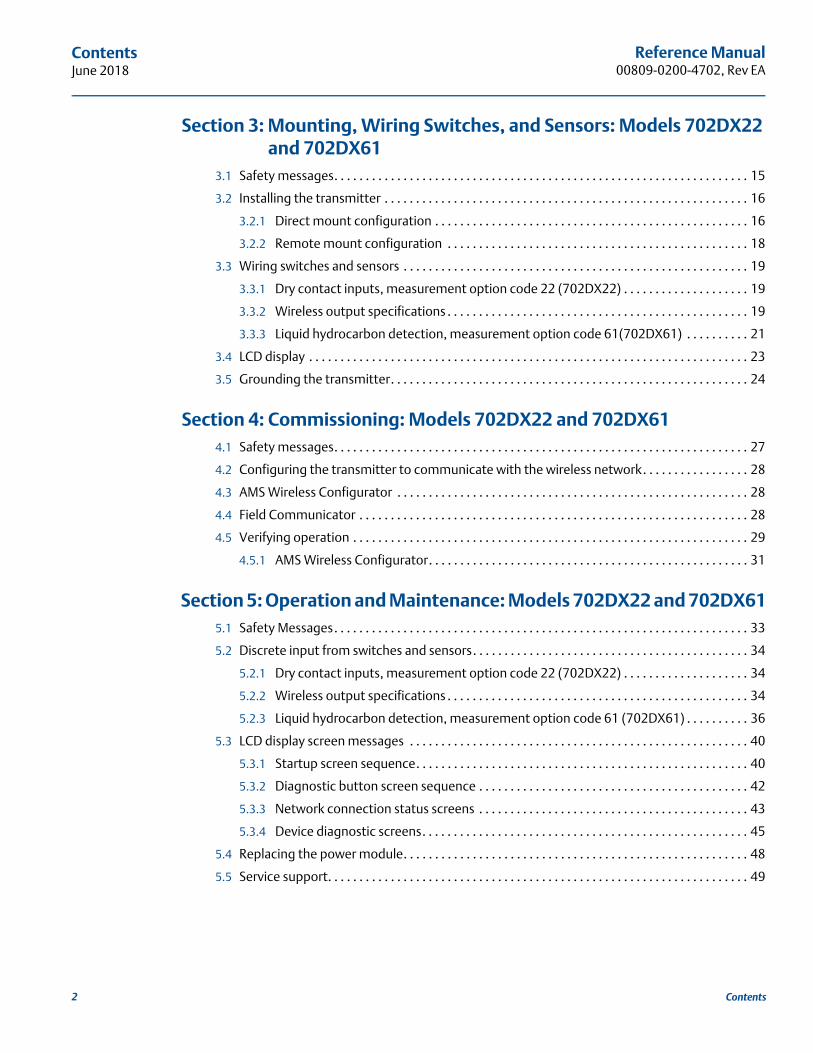
3Section 3: Mounting, Wiring Switches, and Sensors: Models 702DX22 and 702DX61
3.1 Safety messages. . . . . . . . . . . . . . . . . . . . . . . . . . . . . . . . . . . . . . . . . . . . . . . . . . . . . . . . . . . . . . . . . . 15
3.2 Installing the transmitter . . . . . . . . . . . . . . . . . . . . . . . . . . . . . . . . . . . . . . . . . . . . . . . . . . . . . . . . . . 16
3.2.1 Direct mount configuration . . . . . . . . . . . . . . . . . . . . . . . . . . . . . . . . . . . . . . . . . . . . . . . . . . 16
3.2.2 Remote mount configuration . . . . . . . . . . . . . . . . . . . . . . . . . . . . . . . . . . . . . . . . . . . . . . . . 18
3.3 Wiring switches and sensors . . . . . . . . . . . . . . . . . . . . . . . . . . . . . . . . . . . . . . . . . . . . . . . . . . . . . . . 19
3.3.1 Dry contact inputs, measurement option code 22 (702DX22) . . . . . . . . . . . . . . . . . . . . 19
3.3.2 Wireless output specifications . . . . . . . . . . . . . . . . . . . . . . . . . . . . . . . . . . . . . . . . . . . . . . . . 19
3.3.3 Liquid hydrocarbon detection, measurement option code 61(702DX61) . . . . . . . . . . 21
3.4 LCD display . . . . . . . . . . . . . . . . . . . . . . . . . . . . . . . . . . . . . . . . . . . . . . . . . . . . . . . . . . . . . . . . . . . . . . 23
3.5 Grounding the transmitter. . . . . . . . . . . . . . . . . . . . . . . . . . . . . . . . . . . . . . . . . . . . . . . . . . . . . . . . . 24
4Section 4: Commissioning: Models 702DX22 and 702DX614.1 Safety messages. . . . . . . . . . . . . . . . . . . . . . . . . . . . . . . . . . . . . . . . . . . . . . . . . . . . . . . . . . . . . . . . . . 27
4.2 Configuring the transmitter to communicate with the wireless network. . . . . . . . . . . . . . . . . 28
4.3 AMS Wireless Configurator . . . . . . . . . . . . . . . . . . . . . . . . . . . . . . . . . . . . . . . . . . . . . . . . . . . . . . . . 28
4.4 Field Communicator . . . . . . . . . . . . . . . . . . . . . . . . . . . . . . . . . . . . . . . . . . . . . . . . . . . . . . . . . . . . . . 28
4.5 Verifying operation . . . . . . . . . . . . . . . . . . . . . . . . . . . . . . . . . . . . . . . . . . . . . . . . . . . . . . . . . . . . . . . 29
4.5.1 AMS Wireless Configurator. . . . . . . . . . . . . . . . . . . . . . . . . . . . . . . . . . . . . . . . . . . . . . . . . . . 31
5Section 5: Operation and Maintenance: Models 702DX22 and 702DX615.1 Safety Messages. . . . . . . . . . . . . . . . . . . . . . . . . . . . . . . . . . . . . . . . . . . . . . . . . . . . . . . . . . . . . . . . . . 33
5.2 Discrete input from switches and sensors. . . . . . . . . . . . . . . . . . . . . . . . . . . . . . . . . . . . . . . . . . . . 34
5.2.1 Dry contact inputs, measurement option code 22 (702DX22) . . . . . . . . . . . . . . . . . . . . 34
5.2.2 Wireless output specifications . . . . . . . . . . . . . . . . . . . . . . . . . . . . . . . . . . . . . . . . . . . . . . . . 34
5.2.3 Liquid hydrocarbon detection, measurement option code 61 (702DX61) . . . . . . . . . . 36
5.3 LCD display screen messages . . . . . . . . . . . . . . . . . . . . . . . . . . . . . . . . . . . . . . . . . . . . . . . . . . . . . . 40
5.3.1 Startup screen sequence. . . . . . . . . . . . . . . . . . . . . . . . . . . . . . . . . . . . . . . . . . . . . . . . . . . . . 40
5.3.2 Diagnostic button screen sequence . . . . . . . . . . . . . . . . . . . . . . . . . . . . . . . . . . . . . . . . . . . 42
5.3.3 Network connection status screens . . . . . . . . . . . . . . . . . . . . . . . . . . . . . . . . . . . . . . . . . . . 43
5.3.4 Device diagnostic screens. . . . . . . . . . . . . . . . . . . . . . . . . . . . . . . . . . . . . . . . . . . . . . . . . . . . 45
5.4 Replacing the power module. . . . . . . . . . . . . . . . . . . . . . . . . . . . . . . . . . . . . . . . . . . . . . . . . . . . . . . 48
5.5 Service support. . . . . . . . . . . . . . . . . . . . . . . . . . . . . . . . . . . . . . . . . . . . . . . . . . . . . . . . . . . . . . . . . . . 49
2 Contents
Reference Manual 00809-0200-4702, Rev EA
ContentsJune 2018
6Section 6: Configuration: Models 702DX32 and 702DX426.1 Safety messages. . . . . . . . . . . . . . . . . . . . . . . . . . . . . . . . . . . . . . . . . . . . . . . . . . . . . . . . . . . . . . . . . . 51
6.1.1 Ensuring proper switch connections. . . . . . . . . . . . . . . . . . . . . . . . . . . . . . . . . . . . . . . . . . . 52
6.2 Discrete channel configuration . . . . . . . . . . . . . . . . . . . . . . . . . . . . . . . . . . . . . . . . . . . . . . . . . . . . . 52
6.3 Device network configuration . . . . . . . . . . . . . . . . . . . . . . . . . . . . . . . . . . . . . . . . . . . . . . . . . . . . . . 52
6.3.1 Dry contact inputs, measurement option code 32, 42 (Models 702DX32 and 702DX42) . . . . . . . . . . . . . . . . . . . . . . . . . . . . . . . . . . . . . . . . . . . . . 53
6.4 HART menu tree. . . . . . . . . . . . . . . . . . . . . . . . . . . . . . . . . . . . . . . . . . . . . . . . . . . . . . . . . . . . . . . . . . 55
6.4.1 Fast Key sequence . . . . . . . . . . . . . . . . . . . . . . . . . . . . . . . . . . . . . . . . . . . . . . . . . . . . . . . . . . 58
6.5 Removing the power module . . . . . . . . . . . . . . . . . . . . . . . . . . . . . . . . . . . . . . . . . . . . . . . . . . . . . . 58
7Section 7: Mounting, Wiring Switches, and Output Circuits: Models 702DX32 and 702DX42
7.1 Safety messages. . . . . . . . . . . . . . . . . . . . . . . . . . . . . . . . . . . . . . . . . . . . . . . . . . . . . . . . . . . . . . . . . . 59
7.2 Installing the transmitter . . . . . . . . . . . . . . . . . . . . . . . . . . . . . . . . . . . . . . . . . . . . . . . . . . . . . . . . . . 60
7.2.1 Direct mount . . . . . . . . . . . . . . . . . . . . . . . . . . . . . . . . . . . . . . . . . . . . . . . . . . . . . . . . . . . . . . . 60
7.2.2 Remote mount . . . . . . . . . . . . . . . . . . . . . . . . . . . . . . . . . . . . . . . . . . . . . . . . . . . . . . . . . . . . . 62
7.3 Wiring switches and sensors . . . . . . . . . . . . . . . . . . . . . . . . . . . . . . . . . . . . . . . . . . . . . . . . . . . . . . . 63
7.3.1 Dry contact inputs, measurement option code 32, 42 (702DX32, 702DX42) . . . . . . . 63
7.3.2 Dry contact switch inputs . . . . . . . . . . . . . . . . . . . . . . . . . . . . . . . . . . . . . . . . . . . . . . . . . . . . 63
7.3.3 Output circuits, measurement option code 42 (702DX42) . . . . . . . . . . . . . . . . . . . . . . . 65
7.3.4 Safety shower and eye wash monitoring . . . . . . . . . . . . . . . . . . . . . . . . . . . . . . . . . . . . . . . 67
7.4 LCD display . . . . . . . . . . . . . . . . . . . . . . . . . . . . . . . . . . . . . . . . . . . . . . . . . . . . . . . . . . . . . . . . . . . . . . 70
7.5 Grounding the transmitter. . . . . . . . . . . . . . . . . . . . . . . . . . . . . . . . . . . . . . . . . . . . . . . . . . . . . . . . . 71
8Section 8: Commissioning: Models 702DX32 and 702DX428.1 Safety messages. . . . . . . . . . . . . . . . . . . . . . . . . . . . . . . . . . . . . . . . . . . . . . . . . . . . . . . . . . . . . . . . . . 73
8.2 Configuring wireless network communication . . . . . . . . . . . . . . . . . . . . . . . . . . . . . . . . . . . . . . . 74
8.3 Verifying operation . . . . . . . . . . . . . . . . . . . . . . . . . . . . . . . . . . . . . . . . . . . . . . . . . . . . . . . . . . . . . . . 74
8.3.1 AMS Wireless Configurator. . . . . . . . . . . . . . . . . . . . . . . . . . . . . . . . . . . . . . . . . . . . . . . . . . . 77
3Contents

Reference Manual00809-0200-4702, Rev EA
ContentsJune 2018
9Section 9: Operation and Maintenance: Models 702DX32 and 702DX429.1 Safety messages. . . . . . . . . . . . . . . . . . . . . . . . . . . . . . . . . . . . . . . . . . . . . . . . . . . . . . . . . . . . . . . . . . 79
9.2 Discrete input from switches. . . . . . . . . . . . . . . . . . . . . . . . . . . . . . . . . . . . . . . . . . . . . . . . . . . . . . . 80
9.2.1 Dry contact inputs, measurement option code 32, 42 (702DX32, 702DX42) . . . . . . . 80
9.2.2 Wireless output specifications . . . . . . . . . . . . . . . . . . . . . . . . . . . . . . . . . . . . . . . . . . . . . . . . 80
9.2.3 Momentary discrete inputs, measurement option code 32 and 42 (702DX32, 702DX42) . . . . . . . . . . . . . . . . . . . . . . . . . . . . . . . . . . . . . . . . . . . . . . . . . . . . . . . 82
9.3 Discrete output circuits . . . . . . . . . . . . . . . . . . . . . . . . . . . . . . . . . . . . . . . . . . . . . . . . . . . . . . . . . . . 86
9.4 Modbus and OPC mapping . . . . . . . . . . . . . . . . . . . . . . . . . . . . . . . . . . . . . . . . . . . . . . . . . . . . . . . . 90
9.5 Interpreting the LCD display screen messages. . . . . . . . . . . . . . . . . . . . . . . . . . . . . . . . . . . . . . . . 90
9.5.1 Startup screen sequence. . . . . . . . . . . . . . . . . . . . . . . . . . . . . . . . . . . . . . . . . . . . . . . . . . . . . 90
9.5.2 Diagnostic button screen sequence . . . . . . . . . . . . . . . . . . . . . . . . . . . . . . . . . . . . . . . . . . . 92
9.5.3 Network connection status screens . . . . . . . . . . . . . . . . . . . . . . . . . . . . . . . . . . . . . . . . . . . 93
9.5.4 Device diagnostic screens. . . . . . . . . . . . . . . . . . . . . . . . . . . . . . . . . . . . . . . . . . . . . . . . . . . . 95
9.6 Replacing the power module. . . . . . . . . . . . . . . . . . . . . . . . . . . . . . . . . . . . . . . . . . . . . . . . . . . . . . . 97
9.7 Service support. . . . . . . . . . . . . . . . . . . . . . . . . . . . . . . . . . . . . . . . . . . . . . . . . . . . . . . . . . . . . . . . . . . 98
AAppendix A: Reference DataA.1 Product Certifications . . . . . . . . . . . . . . . . . . . . . . . . . . . . . . . . . . . . . . . . . . . . . . . . . . . . . . . . . . . . . 99
A.2 Ordering Information, Specifications, and Drawings . . . . . . . . . . . . . . . . . . . . . . . . . . . . . . . . . . 99
BAppendix B: High Gain Remote Antenna OptionB.1 Safety messages. . . . . . . . . . . . . . . . . . . . . . . . . . . . . . . . . . . . . . . . . . . . . . . . . . . . . . . . . . . . . . . . . 101
B.2 Functional specifications . . . . . . . . . . . . . . . . . . . . . . . . . . . . . . . . . . . . . . . . . . . . . . . . . . . . . . . . . 102
B.3 Installation considerations . . . . . . . . . . . . . . . . . . . . . . . . . . . . . . . . . . . . . . . . . . . . . . . . . . . . . . . . 103
B.4 Transient/lightning considerations . . . . . . . . . . . . . . . . . . . . . . . . . . . . . . . . . . . . . . . . . . . . . . . . 103
B.5 Dimensional drawings . . . . . . . . . . . . . . . . . . . . . . . . . . . . . . . . . . . . . . . . . . . . . . . . . . . . . . . . . . . 104
B.6 Installing the high gain remote antenna . . . . . . . . . . . . . . . . . . . . . . . . . . . . . . . . . . . . . . . . . . . . 105
CAppendix C: Safety Shower MonitoringC.1 Installation instructions . . . . . . . . . . . . . . . . . . . . . . . . . . . . . . . . . . . . . . . . . . . . . . . . . . . . . . . . . . 109
C.2 Installation drawings . . . . . . . . . . . . . . . . . . . . . . . . . . . . . . . . . . . . . . . . . . . . . . . . . . . . . . . . . . . . . 111
4 Contents
5
Reference Manual 00809-0200-4702, Rev EA
Title PageJune 2018
Title Page
Rosemount™ 702 Wireless Discrete Transmitter
NOTICE
Read this manual before working with the product. For personal and system safety, and for optimum product performance, make sure to thoroughly understand the contents before installing, using, or maintaining this product.
The United States has two toll-free assistance numbers and one international number.
Customer Central1 800 999 9307 (7:00 a.m. to 7:00 p.m. CST)
National Response Center1 800 654 7768 (24 hours a day)Equipment service needs
International1 952 906 8888
The products described in this document are NOT designed for nuclear-qualified applications.
Using non-nuclear qualified products in applications that require nuclear-qualified hardware or products may cause inaccurate readings.
For information on Rosemount nuclear-qualified products, contact an Emerson™ Sales Representative.
Explosions could result in death or serious injury.
Installation of this transmitter in an explosive environment must be in accordance with the appropriate local, national, and international standards, codes, and practices.
Review the approvals section of this manual for any restrictions associated with a safe installation.
Before connecting a Field Communicator in an explosive atmosphere, ensure the instruments are installed in accordance with intrinsically safe or non-incendive field wiring practices.
Process leaks may cause harm or result in death.
Install and tighten process connectors before applying pressure.
Electrical shock can result in death or serious injury.
Avoid contact with the leads and terminals. High voltage that may be present on leads can cause electrical shock.

6
Reference Manual00809-0200-4702, Rev EA
Title PageJune 2018
Title Page
The Rosemount 702 Transmitter and all other wireless devices should be installed only after the Emerson Wireless Gateway has been installed and is functioning properly. Wireless devices should also be powered up in order of proximity from the Gateway, beginning with the closest. This will result in a simpler and faster network installation.
Shipping considerations for wireless products.
The unit was shipped to you without the power module installed. Remove the power module prior to shipping.
Each power module contains two “C” size primary lithium batteries. Primary lithium batteries are regulated in transportation by the U. S. Department of Transportation, and are also covered by IATA (International Air Transport Association), ICAO (International Civil Aviation Organization), and ARD (European Ground Transportation of Dangerous Goods). It is the responsibility of the shipper to ensure compliance with these or any other local requirements. Consult current regulations and requirements before shipping.
The power module with the wireless unit contains two “C” size primary lithium/thionyl chloride batteries. Each battery contains approximately 2.5 grams of lithium, for a total of 5 grams in each pack. Under normal conditions, the battery materials are self-contained and are not reactive as long as the batteries and the pack integrity are maintained. Care should be taken to prevent thermal, electrical, or mechanical damage. Contacts should be protected to prevent premature discharge.
Battery hazards remain when cells are discharged.
Power modules should be stored in a clean and dry area. For maximum battery life, storage temperature should not exceed 30 °C.
The power module has surface resistivity greater than one gigaohm and must be properly installed in the wireless device enclosure. Care must be taken during transportation to and from the point of installation to prevent electrostatic charge build-up.

Reference Manual 00809-0200-4702, Rev EA
IntroductionJune 2018
Section 1 Introduction
1.1 Using this manualThe sections in this manual provide information on installing, operating, and maintaining the Rosemount™ 702 Wireless Discrete Transmitter. Section 2 through Section 5 are for the Rosemount 702DX22 and Rosemount 702DX61 models. The Rosemount 702DX22 is the legacy 702 Transmitter that has discrete input function only. The Rosemount 702DX61 is a special version for liquid hydrocarbon leak detection with Tyco® TraceTek® Sensors. Section 6 through Section 9 are for the Rosemount 702DX32 and Rosemount 702DX42 models. The Rosemount 702DX32 has all of the functionality of the 702DX22, with the addition of momentary discrete input sensing and counting. The 702DX42 adds the capability of discrete output switching.
The manual sections are organized as follows:
Section 2: Configuration: Models 702DX22 and 702DX61 contains information on the configuration of the Rosemount 702 Transmitter so that it can be added to the wireless network. This configuration can be done using the AMS Suite Wireless Configurator or a Field Communicator. Field Communicator menu trees are here.
Section 3: Mounting, Wiring Switches, and Sensors: Models 702DX22 and 702DX61 contains information on the mounting of the Rosemount 702 Transmitter and wiring of switches and sensor to the transmitter.
Section 4: Commissioning: Models 702DX22 and 702DX61 contains information for the commissioning of the Rosemount 702 Transmitter onto the wireless network, and how to verify that the transmitter has successfully joined.
Section 5: Operation and Maintenance: Models 702DX22 and 702DX61 provides detailed information on operation of the Rosemount 702 Transmitter with various switch and sensor configurations. LCD display messages are shown. Power Module replacement is described.
Section 6: Configuration: Models 702DX32 and 702DX42 contains information on the configuration of the Rosemount 702 Transmitter so that it can be added to the wireless network. This configuration can be done using the AMS Wireless Configurator or a Field Communicator. Field Communicator menu trees are here.
Section 7: Mounting, Wiring Switches, and Output Circuits: Models 702DX32 and 702DX42 contains information on the mounting of the Rosemount 702 Transmitter and wiring of switches and sensor to the transmitter.
Section 8: Commissioning: Models 702DX32 and 702DX42 contains information for the commissioning of the Rosemount 702 Transmitter onto the wireless network, and how to verify that the transmitter has successfully joined.
Model number Functionality Manual sections
702DX22 Two channel discrete input 1, 2, 3, 4, 5
702DX61 One channel for Tyco TraceTek liquid hydrocarbon leak detection 1, 2, 3, 4, 5
702DX32 Two channel discrete input with momentary input detection and counting 1, 6, 7, 8, 9
702DX42 Two channel discrete input or discrete output, with momentary input detection and counting
1, 6, 7, 8, 9
1Introduction

Reference Manual00809-0200-4702, Rev EA
IntroductionJune 2018
Section 9: Operation and Maintenance: Models 702DX32 and 702DX42 provides detailed information on operation of the Rosemount 702 Transmitter with various switch and sensor configurations. Also described are: Momentary discrete input detection and counting, discrete output switch function, and variable reporting and mapping. LCD display messages are shown. Power module replacement is described.
Appendix A: Reference Data supplies procedure on how to get the specifications, ordering information, and product certification.
Appendix B: Product Certifications contains telecommunication compliance information, ordinary location certification, hazardous locations certificates and intrinsic safety installation drawings.
Appendix C: High Gain Remote Antenna Option describes the high gain remote antenna, its specifications and installation.
1.2 Models coveredThe following Rosemount 702 Transmitters are covered by this manual:
1.2.1 Rosemount 702DX22 Wireless Discrete Transmitter Two input channels
Discrete input only
1.2.2 Rosemount 702DX61 Wireless Discrete Transmitter for liquid hydrocarbon leak detection Detects hydrocarbon leaks using Tyco TraceTek Sensor
Color coded terminal block for easy wiring of Tyco sensors
Compatible with Tyco TT5000 TraceTek Fuel Sensing cable
Compatible with Tyco TT-FSS TraceTek Fast Fuel Sensor
1.2.3 Rosemount 702DX32 Wireless Discrete Transmitter Two discrete input channels
Momentary input detection and counting
1.2.4 Rosemount 702DX42 Wireless Discrete Transmitter Two channels
Each channel configurable to discrete input or discrete output
Momentary input detection and counting
Discrete output switch function
2 Introduction

Reference Manual 00809-0200-4702, Rev EA
IntroductionJune 2018
3Introduction
1.3 Transmitter overviewFeatures of the Rosemount 702 Transmitter include: An installation-ready solution that provides a variety of mounting options, transmitter configurations,
and switches
Flexibility to meet your most demanding applications
Wireless output with >99percent data reliability delivers rich HART® data, protected by industry leading security
Single or dual switch input with logic for limit contact and opposing contact applications
The integral LCD display conveniently displays the primary switch input and diagnostics of the transmitter
Simple and easy installation practices currently being used for robust installations
1.3.1 Functions of the transmitterSwitches produce either an open or closed signal. By using simple HART configuration, the transmitter converts the switch signal to a wireless-enabled signal.
1.3.2 Wireless considerations
Power up sequence
The Emerson™ Wireless Gateway should be installed and functioning properly before any wireless field devices are powered. Install the Black Power Module, SmartPower™ Solutions model number 701PBKKF (part number 00753-9220-0001) into the Rosemount 702 Transmitter to power the device. Wireless devices should also be powered up in order of proximity from the Gateway, beginning with the closest. This will result in a simpler and faster network installation. Enable Active Advertising on the Gateway to ensure that new devices join the network faster. For more information see the Emerson Wireless Gateway Reference Manual.
Antenna positionThe antenna should be positioned vertically, either straight up or straight down, and it should be approximately 3 ft. (1 m) from any large structure, building, or conductive surface to allow for clear communication to other devices.
Figure 1-1. Antenna Position
Reference Manual00809-0200-4702, Rev EA
IntroductionJune 2018
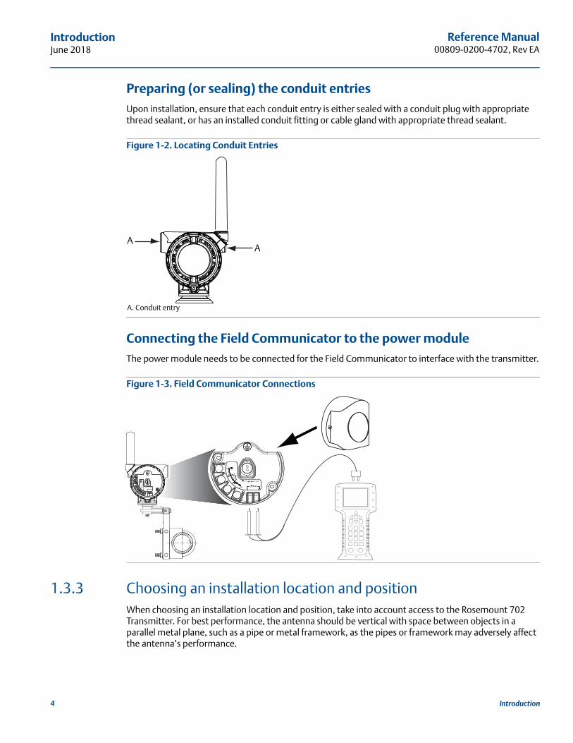
Preparing (or sealing) the conduit entries Upon installation, ensure that each conduit entry is either sealed with a conduit plug with appropriate thread sealant, or has an installed conduit fitting or cable gland with appropriate thread sealant.
Figure 1-2. Locating Conduit Entries
A. Conduit entry
Connecting the Field Communicator to the power moduleThe power module needs to be connected for the Field Communicator to interface with the transmitter.
Figure 1-3. Field Communicator Connections
1.3.3 Choosing an installation location and positionWhen choosing an installation location and position, take into account access to the Rosemount 702 Transmitter. For best performance, the antenna should be vertical with space between objects in a parallel metal plane, such as a pipe or metal framework, as the pipes or framework may adversely affect the antenna’s performance.
AA
COMM
P/N 00753-9200-0020
1
2
3
4
4 Introduction
Reference Manual 00809-0200-4702, Rev EA
IntroductionJune 2018
1.3.4 Electrical
Caring for the power moduleThe Rosemount 702 Transmitter is self-powered. The included Black Power Module contains two “C” size primary lithium/thionyl chloride batteries. Each battery contains approximately 2.5 grams of lithium, for a total of 5 grams in each pack. Under normal conditions, the battery materials are self-contained and are not reactive as long as the batteries and the power module are maintained. Care should be taken to prevent thermal, electrical, or mechanical damage. Contacts should be protected to prevent premature discharge.
Use caution when handling the power module, it may be damaged if dropped from heights in excess of 20 ft. (6,10 m).
Making switch connectionsMake switch connections through the cable entry in the side of the connection head. Be sure to provide adequate clearance for cover removal.
1.3.5 Verifying operating atmosphereVerify that the operating atmosphere of the transmitter is consistent with the appropriate hazardous locations certifications.
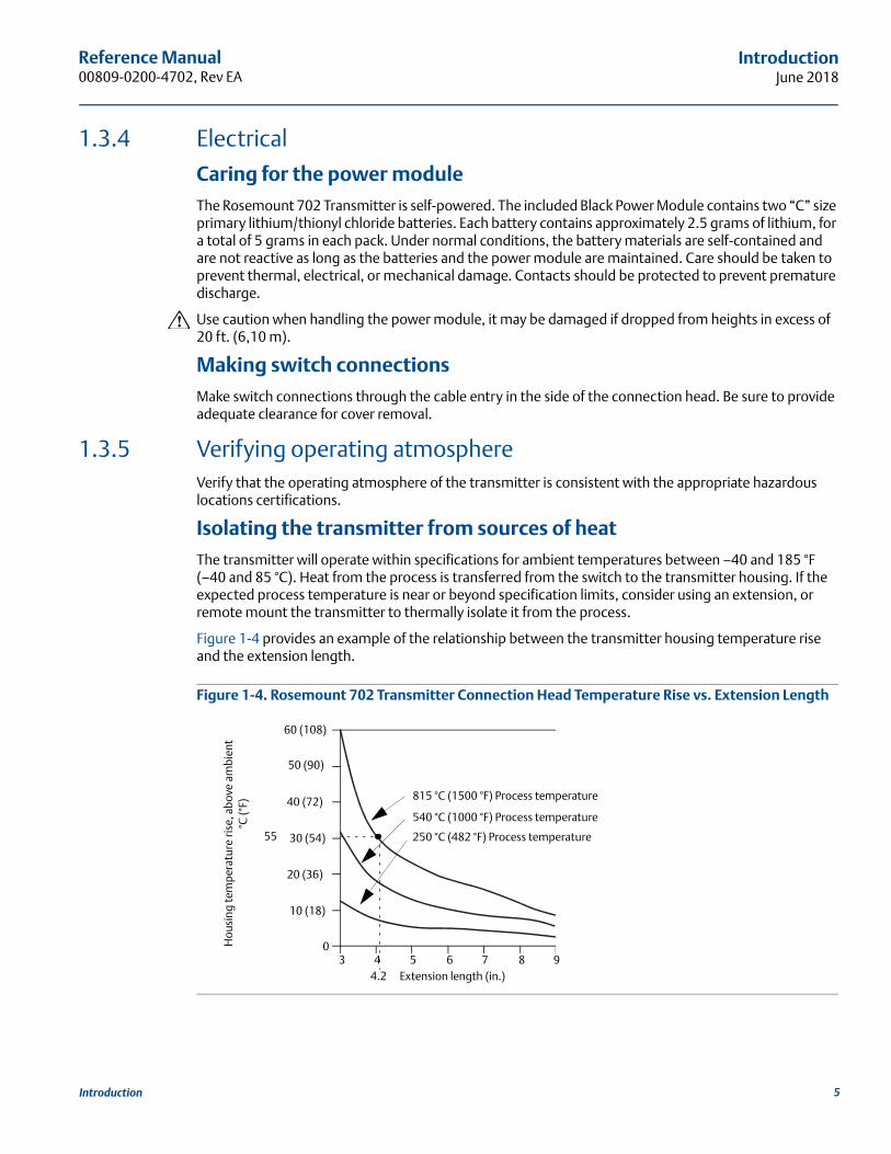
Isolating the transmitter from sources of heatThe transmitter will operate within specifications for ambient temperatures between –40 and 185 °F (–40 and 85 °C). Heat from the process is transferred from the switch to the transmitter housing. If the expected process temperature is near or beyond specification limits, consider using an extension, or remote mount the transmitter to thermally isolate it from the process.
Figure 1-4 provides an example of the relationship between the transmitter housing temperature rise and the extension length.
Figure 1-4. Rosemount 702 Transmitter Connection Head Temperature Rise vs. Extension Length
Hou
sing
tem
pera
ture
rise
, abo
ve a
mbi
ent
°C (°
F)
3 4 5 6 7 8 90
60 (108)
50 (90)
40 (72)
30 (54)
20 (36)
10 (18)
4.2
55
Extension length (in.)
815 °C (1500 °F) Process temperature
540 °C (1000 °F) Process temperature
250 °C (482 °F) Process temperature
5Introduction
Reference Manual00809-0200-4702, Rev EA
IntroductionJune 2018
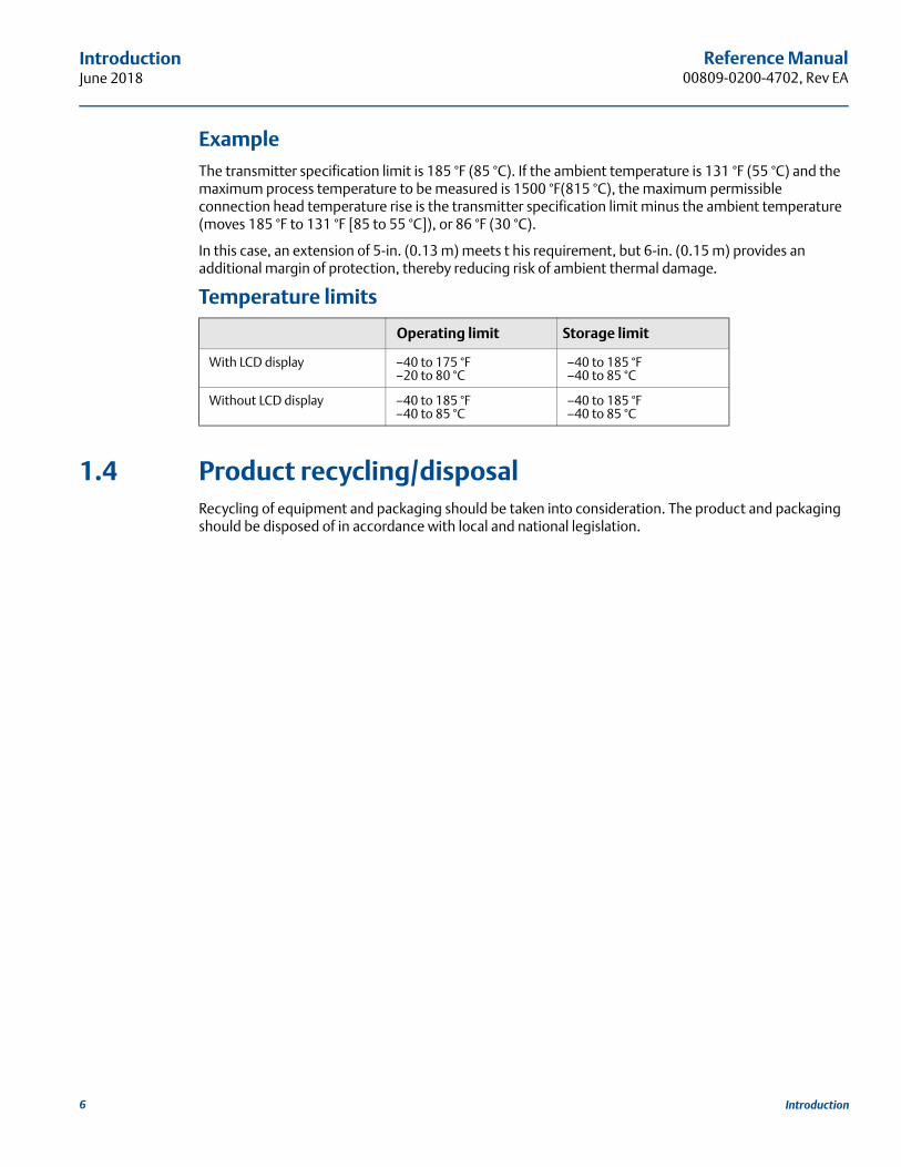
ExampleThe transmitter specification limit is 185 °F (85 °C). If the ambient temperature is 131 °F (55 °C) and the maximum process temperature to be measured is 1500 °F(815 °C), the maximum permissible connection head temperature rise is the transmitter specification limit minus the ambient temperature (moves 185 °F to 131 °F [85 to 55 °C]), or 86 °F (30 °C).
In this case, an extension of 5-in. (0.13 m) meets t his requirement, but 6-in. (0.15 m) provides an additional margin of protection, thereby reducing risk of ambient thermal damage.
Temperature limits
1.4 Product recycling/disposalRecycling of equipment and packaging should be taken into consideration. The product and packaging should be disposed of in accordance with local and national legislation.
Operating limit Storage limit
With LCD display –40 to 175 °F–20 to 80 °C
–40 to 185 °F–40 to 85 °C
Without LCD display –40 to 185 °F–40 to 85 °C
–40 to 185 °F–40 to 85 °C
6 Introduction

Reference Manual 00809-0200-4702, Rev EA
Configuration: Models 702DX22 and 702DX61June 2018
Section 2 Configuration: Models 702DX22 and 702DX61
Safety messages . . . . . . . . . . . . . . . . . . . . . . . . . . . . . . . . . . . . . . . . . . . . . . . . . . . . . . . . . . . . . . . . . . . . . . page 7Configuring the Device Sensor . . . . . . . . . . . . . . . . . . . . . . . . . . . . . . . . . . . . . . . . . . . . . . . . . . . . . . . . . page 8Configuring the device network . . . . . . . . . . . . . . . . . . . . . . . . . . . . . . . . . . . . . . . . . . . . . . . . . . . . . . . . page 9HART menu tree . . . . . . . . . . . . . . . . . . . . . . . . . . . . . . . . . . . . . . . . . . . . . . . . . . . . . . . . . . . . . . . . . . . . . . page 11Remove power module . . . . . . . . . . . . . . . . . . . . . . . . . . . . . . . . . . . . . . . . . . . . . . . . . . . . . . . . . . . . . . . . page 13
2.1 Safety messagesInstructions and procedures in this section may require special precautions to ensure the safety of the personnel performing the operations. Information that potentially raises safety issues is indicated by a warning symbol ( ). Refer to the following safety messages before performing an operation preceded by this symbol.
2.1.1 Connecting the switchesThe Rosemount™ 702 Wireless Discrete Transmitter is compatible with a number of simple switches. When ordered in the optional configuration for Liquid Hydrocarbon Detection, option code 61, the transmitter is compatible with Tyco® TraceTek® Fast Fuel Sensors and TraceTek Sensing cable. Figure 2-1 on page 9 shows the correct input connections to the switch terminals on the transmitter. To ensure a proper switch connection, anchor the switch lead wires into the appropriate compression terminals and tighten the screws.
Failure to follow these installation guidelines could result in death or serious injury.
Only qualified personnel should perform the installation.
Explosions could result in death or serious injury. Before connecting a Field Communicator in an explosive atmosphere, make sure that the
instruments are installed in accordance with intrinsically safe or non-incendive field wiring practices.
Verify that the operating atmosphere of the transmitter is consistent with the appropriate hazardous locations certifications.
Process leaks could result in death or serious injury. Do not remove the switch while in operation.
Install and tighten switches before applying pressure.
Electrical shock could cause death or serious injury.
Use extreme caution when making contact with the leads and terminals
7Configuration: Models 702DX22 and 702DX61

Reference Manual00809-0200-4702, Rev EA
Configuration: Models 702DX22 and 702DX61 June 2018
Wiring the transmitterIf the switch is installed in a high-voltage environment and a fault condition or installation error occurs, the sensor leads and transmitter terminals could carry lethal voltage. Use extreme caution when making contact with the leads and terminals.
Use the following steps to wire the sensor and power supply to the transmitter:
1. Remove the transmitter enclosure cover (if applicable).
2. Attach the sensor leads according to the wiring diagram Figure 2-2 on page 10.
3. Connect the Black Power Module.
4. Verify the connection by viewing the LCD.
5. Replace the cover and tighten (if applicable).
2.2 Configuring the Device SensorRemove the power module-side housing cover to expose the terminal block and HART® Communication terminals, then connect the power module to power the unit for configuration. The Rosemount 702 Transmitter will receive any HART Communication from a Field Communicator, or AMS Wireless Configurator.
2.3 Configuring on the bench Field CommunicatorWhen using a Field Communicator, any configuration changes must be sent to the transmitter using the Send key (F2). AMS Wireless Configurator configuration changes are implemented when the Apply button is clicked.
AMS Wireless ConfiguratorAMS Wireless Configurator is capable of connecting to devices directly, using a HART modem, or with the Gateway. When configuring on the bench with a HART modem, double click the device icon, then select the Configure/Setup tab (or right click and select Configure/Setup). Configure the device settings using the Direct Connection menu. When configuring with the Gateway, double click the device icon then select the Configure/Setup tab (or right click and select Configure/Setup). Configure the device settings using the Wireless Connection menu. To check or change sensor configuration using a Field Communicator, enter the following Fast Key Sequence: 2, 2, 2.
8 Configuration: Models 702DX22 and 702DX61

Reference Manual 00809-0200-4702, Rev EA
Configuration: Models 702DX22 and 702DX61June 2018
2.4 Configuring the device networkField CommunicatorTo communicate with the Gateway, and ultimately the information system, the transmitter must be configured to communicate with the wireless network.
Using a Field Communicator or AMS Wireless Configurator, enter the Network ID and Join Key so they match the Network ID and Join Key of the Gateway and the other devices in the network. If the Network ID and Join Key are not identical, the transmitter will not communicate with the network. The Network ID and Join Key may be obtained from the Gateway on the Setup>Network>Settings page on the web server. Using a Field Communicator, the Network ID can be configured by entering the Fast Key Sequence: 2, 2, 1, 1. The Join Key can also be configured using a Field Communicator with the Fast Key Sequence: 2, 2, 1, 2.
AMS Wireless ConfiguratorThe final device network configuration piece is the Update Rate which, by default, is 1 minute. It can be changed at commissioning, or at any time, by using AMS Wireless Configurator or the Gateway’s web server. The update rate should be between 4 seconds and 60 minutes. To change the Update Rate with a Field Communicator, use the Fast Key Sequence: 2, 2, 1, 3.
If doing a bench top initial configuration, after completion remove the power module until installation. When the device is installed, insert he power module and close the housing cover securely. Always ensure a proper seal so that metal touches metal, but do not overtighten.
2.4.1 Configuring transmitter with dry contact inputs, measurement option code 22 (702DX22)
Figure 2-1. Terminal Block
Connect the HART Communication leads to the COMM terminals on the terminal block.
9Configuration: Models 702DX22 and 702DX61
Reference Manual00809-0200-4702, Rev EA
Configuration: Models 702DX22 and 702DX61 June 2018
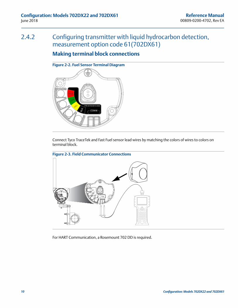
2.4.2 Configuring transmitter with liquid hydrocarbon detection, measurement option code 61(702DX61)
Making terminal block connections
Figure 2-2. Fuel Sensor Terminal Diagram
Connect Tyco TraceTek and Fast Fuel sensor lead wires by matching the colors of wires to colors on terminal block.
Figure 2-3. Field Communicator Connections
For HART Communication, a Rosemount 702 DD is required.
COMM
P/N 00753-9200-0020
1
2
3
4
10 Configuration: Models 702DX22 and 702DX61
11
Reference Manual 00809-0200-4702, Rev EA
Configuration: Models 702DX22 and 702DX61June 2018
Co
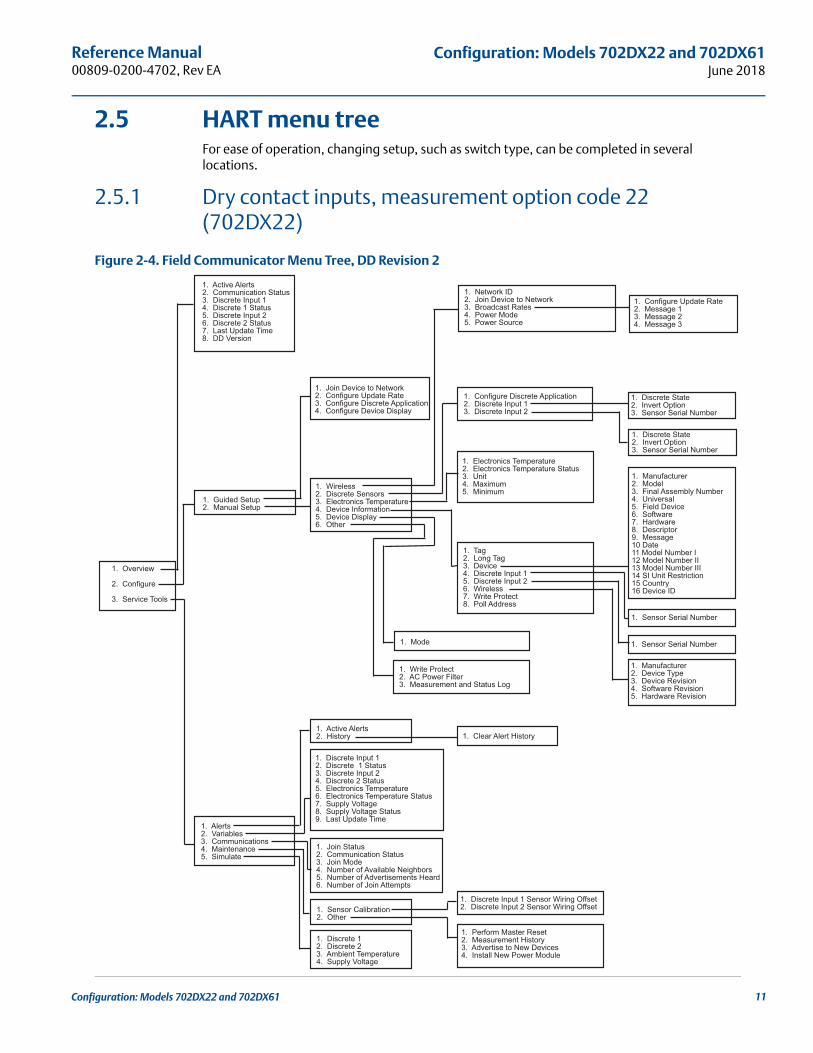
nfiguration: Models 702DX22 and 702DX612.5 HART menu treeFor ease of operation, changing setup, such as switch type, can be completed in several locations.
2.5.1 Dry contact inputs, measurement option code 22 (702DX22)
Figure 2-4. Field Communicator Menu Tree, DD Revision 2
1. Overview
2. Configure
3. Service Tools
1. Active Alerts2. Communication Status3. Discrete Input 14. Discrete 1 Status5. Discrete Input 26. Discrete 2 Status7. Last Update Time8. DD Version
1. Guided Setup2. Manual Setup
1. Alerts2. Variables3. Communications4. Maintenance5. Simulate
1. Join Device to Network 2. Configure Update Rate3. Configure Discrete Application4. Configure Device Display
1. Wireless2. Discrete Sensors3. Electronics Temperature4. Device Information5. Device Display6. Other
1. Active Alerts2. History
1. Discrete Input 12. Discrete 1 Status3. Discrete Input 24. Discrete 2 Status5. Electronics Temperature6. Electronics Temperature Status7. Supply Voltage8. Supply Voltage Status9. Last Update Time
1. Join Status2. Communication Status3. Join Mode4. Number of Available Neighbors5. Number of Advertisements Heard6. Number of Join Attempts
1. Sensor Calibration2. Other
1. Discrete 12. Discrete 23. Ambient Temperature4. Supply Voltage
1. Clear Alert History
1. Discrete Input 1 Sensor Wiring Offset2. Discrete Input 2 Sensor Wiring Offset
1. Perform Master Reset2. Measurement History3. Advertise to New Devices4. Install New Power Module
1. Network ID2. Join Device to Network3. Broadcast Rates4. Power Mode5. Power Source
1. Configure Discrete Application2. Discrete Input 13. Discrete Input 2
1. Electronics Temperature2. Electronics Temperature Status3. Unit4. Maximum5. Minimum
1. Tag2. Long Tag3. Device4. Discrete Input 15. Discrete Input 26. Wireless7. Write Protect8. Poll Address
1. Mode
1. Write Protect2. AC Power Filter3. Measurement and Status Log
1. Configure Update Rate2. Message 13. Message 24. Message 3
1. Discrete State2. Invert Option3. Sensor Serial Number
1. Discrete State2. Invert Option3. Sensor Serial Number
1. Manufacturer2. Model3. Final Assembly Number4. Universal5. Field Device6. Software7. Hardware8. Descriptor9. Message10 Date11 Model Number I12 Model Number II13 Model Number III14 SI Unit Restriction15 Country16 Device ID
1. Sensor Serial Number
1. Sensor Serial Number
1. Manufacturer2. Device Type3. Device Revision4. Software Revision5. Hardware Revision

Reference Manual00809-0200-4702, Rev EA
Configuration: Models 702DX22 and 702DX61 June 2018
2.5.2 Liquid hydrocarbon detection, measurement option code 61(702DX61)
Figure 2-5. Field Communicator Menu Tree, DD Revision 1, for Leak Detection
1. Overview
2. Configure
3. Service Tools
1. Device Status2. Communication Status3. Sensor State4. Sensor Status5. Update Rate6. DD Revision
1. Guided Setup2. Manual Setup
1. Alerts2. Variables3. Communications4. Routine Maintenance5. Simulate
1. Join Device to Network 2. Configure Update Rate3. Configure Sensor
1. Wireless2. Leak Sensor3. Electronics Temperature4. Device Information5. Other
1. Refresh Alerts2. History
1. Sensor State2. Sensor Status3. Electronics Temperature4. Electronics temperature Status5. Supply Voltage6. Supply Voltage Status7. Last Update Time
1. Join Status2. Communication Status3. Join Mode4. Number of Available Neighbors5. Number of Advertisements Heard6. Number of Join Attempts
1. Other
1. Input2. Electronics Temperature3. Supply Voltage
1. Perform Master Reset2. Measurement History3. Advertise to New Devices4. Install New Power Module
1. Network ID2. Join Device to Network 3. Broadcast Rates
1. Configure Sensor2. Sensor State3. Sensor Status4. Sensor Serial Number
1. Electronics Temperature2. Electronics Temperature Status3. Unit4. Maximum5. Minimum
1. Tag2. Long Tag3. Device4. Leak Sensor5. Wireless6. Write Protect7. Polling Address
1. Write Protect2. AC Power Filter3. Measurement and Status Log4. Power Mode5. Power Source
1. Configure Update Rate2. Message 13. Message 24. Message 3
1. Manufacturer2. Model3. Final Assembly Number4. Universal5. Field Device6. Software7. Hardware8. Descriptor9. Message10 Date11 Model Number I12 Model Number II13 Model Number III14 SI Unit Restriction15 Country16 Device ID
1. Sensor Serial Number
1. Manufacturer2. Device Type3. Device Revision4. Software Revision5. Hardware Revision6. Transmit Power Level
12 Configuration: Models 702DX22 and 702DX61

Reference Manual 00809-0200-4702, Rev EA
Configuration: Models 702DX22 and 702DX61June 2018
2.5.3 Fast Key sequenceTable lists the Fast Key sequence for common transmitter functions.
NoteThe Fast Key sequences assume that a current DD is being used: DD Rev 2 for dry contact inputs, and DD Rev 1 for leak detection.
2.6 Remove power moduleAfter the sensor and network have been configured, remove the power module and replace the transmitter cover. The power module should be inserted only when the device is ready for commissioning.
Table 2-1. Rosemount 702 Fast Key sequence
Function Key sequence Menu items
Device Information 2, 2, 4Manufacturer, Model, Final Assembly Number, Universal, Field Device, Software, Hardware Descriptor, Message, Date, Model Number, I, II, III, SI Unit Restriction, Country
Guided Setup 2, 1Join Device to Network, Configure Update Rate, Configure Sensor, Calibrate Sensor, Configure Display, Configure Process Alarms
Manual Setup 2, 2 Wireless, Process Sensor, Percent of Range, Device Temperature, Device Information, Device Configure, Other
Wireless 2, 2, 1 Network ID, Join Device to Network, Configure Update Rate, Configure Broadcast Power Level, Power Mode, Power Source
Discrete Input Configuration 2, 2, 2 Discrete Input Configuration
13Configuration: Models 702DX22 and 702DX61

14
Reference Manual00809-0200-4702, Rev EA
Configuration: Models 702DX22 and 702DX61 June 2018
Configuration: Models 702DX22 and 702DX61
Reference Manual 00809-0200-4702, Rev EA
Mounting, Wiring Switches, and Sensors:Models 702DX22 and 702DX61
June 2018
Section 3 Mounting, Wiring Switches, and Sensors: Models 702DX22 and 702DX61
Safety messages . . . . . . . . . . . . . . . . . . . . . . . . . . . . . . . . . . . . . . . . . . . . . . . . . . . . . . . . . . . . . . . . . . . . . . page 15Installing the transmitter . . . . . . . . . . . . . . . . . . . . . . . . . . . . . . . . . . . . . . . . . . . . . . . . . . . . . . . . . . . . . . page 16Wiring switches and sensors . . . . . . . . . . . . . . . . . . . . . . . . . . . . . . . . . . . . . . . . . . . . . . . . . . . . . . . . . . . page 19LCD display . . . . . . . . . . . . . . . . . . . . . . . . . . . . . . . . . . . . . . . . . . . . . . . . . . . . . . . . . . . . . . . . . . . . . . . . . . page 23Grounding the transmitter . . . . . . . . . . . . . . . . . . . . . . . . . . . . . . . . . . . . . . . . . . . . . . . . . . . . . . . . . . . . . page 24
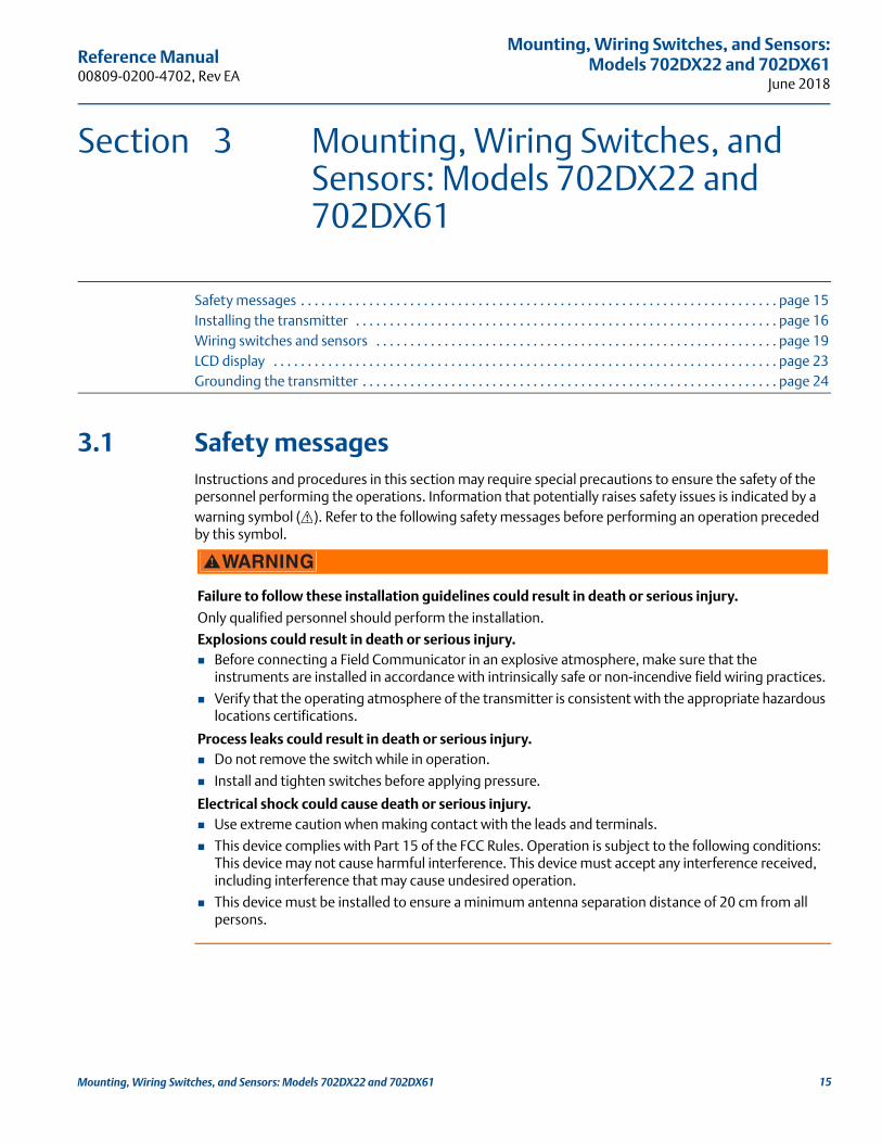
3.1 Safety messagesInstructions and procedures in this section may require special precautions to ensure the safety of the personnel performing the operations. Information that potentially raises safety issues is indicated by a warning symbol ( ). Refer to the following safety messages before performing an operation preceded by this symbol.
Failure to follow these installation guidelines could result in death or serious injury.
Only qualified personnel should perform the installation.
Explosions could result in death or serious injury. Before connecting a Field Communicator in an explosive atmosphere, make sure that the
instruments are installed in accordance with intrinsically safe or non-incendive field wiring practices.
Verify that the operating atmosphere of the transmitter is consistent with the appropriate hazardous locations certifications.
Process leaks could result in death or serious injury. Do not remove the switch while in operation.
Install and tighten switches before applying pressure.
Electrical shock could cause death or serious injury. Use extreme caution when making contact with the leads and terminals.
This device complies with Part 15 of the FCC Rules. Operation is subject to the following conditions: This device may not cause harmful interference. This device must accept any interference received, including interference that may cause undesired operation.
This device must be installed to ensure a minimum antenna separation distance of 20 cm from all persons.
15Mounting, Wiring Switches, and Sensors: Models 702DX22 and 702DX61
Reference Manual00809-0200-4702, Rev EA
Mounting, Wiring Switches, and Sensors: Models 702DX22 and 702DX61June 2018
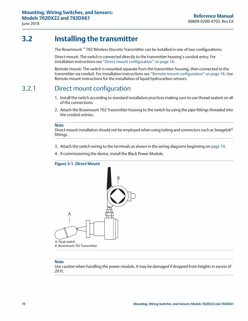
3.2 Installing the transmitterThe Rosemount ™ 702 Wireless Discrete Transmitter can be installed in one of two configurations:
Direct mount: The switch is connected directly to the transmitter housing’s conduit entry. For installation instructions see “Direct mount configuration” on page 16.
Remote mount: The switch is mounted separate from the transmitter housing, then connected to the transmitter via conduit. For installation instructions see “Remote mount configuration” on page 18. Use Remote mount instructions for the installation of liquid hydrocarbon sensors.
3.2.1 Direct mount configuration1. Install the switch according to standard installation practices making sure to use thread sealant on all
of the connections.
2. Attach the Rosemount 702 Transmitter housing to the switch by using the pipe fittings threaded into the conduit entries.
NoteDirect mount installation should not be employed when using tubing and connectors such as Swagelok® fittings.
3. Attach the switch wiring to the terminals as shown in the wiring diagrams beginning on page 19.
4. If commissioning the device, install the Black Power Module.
Figure 3-1. Direct Mount
A. Float switchB. Rosemount 702 Transmitter
NoteUse caution when handling the power module, it may be damaged if dropped from heights in excess of 20 ft.
A
B
16 Mounting, Wiring Switches, and Sensors: Models 702DX22 and 702DX61

Reference Manual 00809-0200-4702, Rev EA
Mounting, Wiring Switches, and Sensors:Models 702DX22 and 702DX61
June 2018
NoteWireless devices should only be powered up after the Emerson™ Wireless Gateway, in order of proximity from the Gateway beginning with the closest device. This results in a simpler and faster network installation.
Figure 3-2. Power Module Installation
5. Close the housing cover and tighten to safety specifications. Always ensure a proper seal by installing the electronic housing covers so that metal touches metal, but do not overtighten.
6. Position the antenna such that it is vertical, either straight up or straight down, as shown in Figure 3-3. The antenna should be approximately 3 ft. (1 m) from any large structures or buildings, to allow clear communication to other devices.
Figure 3-3. Antenna Positioning
Possible antenna rotation shown.Antenna rotation allows for bestinstallation practices in anyconfiguration.
17Mounting, Wiring Switches, and Sensors: Models 702DX22 and 702DX61

Reference Manual00809-0200-4702, Rev EA
Mounting, Wiring Switches, and Sensors: Models 702DX22 and 702DX61June 2018
3.2.2 Remote mount configuration1. Install the switch according to standard installation practices being sure to use thread sealant on all of
the connections.
2. Run wiring (and conduit, if necessary) from the switch to the Rosemount 702 Transmitter.
3. Pull the wiring through the threaded conduit entry.
4. Attach the switch wiring to the terminals as shown in the wiring diagrams beginning on page 19.
5. If commissioning the Transmitter, connect the Power Module as shown in Figure 3-2 on page 17.
Figure 3-4. Remote Mount
A. Float switchB. Rosemount 702 Transmitter
NoteUse caution when handling the power module, it may be damaged if dropped from heights in excess of 20 ft.
NoteWireless devices should only be powered up after the Emerson Wireless Gateway, in order of proximity from the Gateway beginning with the closest device. This results in a simpler and faster network installation.
6. Close the housing cover and tighten to safety specifications. Always ensure a proper seal by installing the electronic housing covers so that metal touches metal, but do not overtighten.
7. Position the antenna such that it is vertical, either straight up or straight down, as shown in Figure 3-3 on page 17. The antenna should be approximately 3 ft. (1 m) from any large structures or buildings, to allow clear communication to other devices.
A
B
18 Mounting, Wiring Switches, and Sensors: Models 702DX22 and 702DX61

Reference Manual 00809-0200-4702, Rev EA
Mounting, Wiring Switches, and Sensors:Models 702DX22 and 702DX61
June 2018
3.3 Wiring switches and sensors
3.3.1 Dry contact inputs, measurement option code 22 (702DX22)
Figure 3-5. Terminal Diagram
3.3.2 Wireless output specifications
Dual inputThe Rosemount 702 Transmitter will accept the input from one or two single pole single throw switches on inputs S1 and S2. The wireless output of the transmitter will be both a primary variable (PV) and a secondary variable (SV). The PV is determined by the S1 input. The SV is determined by the S2 input. A closed switch drives a TRUE output. An open switch drives a FALSE output.
Figure 3-6. Single and Dual Input
Single input Dual input
S1
CMN
S2
CMN
19Mounting, Wiring Switches, and Sensors: Models 702DX22 and 702DX61

Reference Manual00809-0200-4702, Rev EA
Mounting, Wiring Switches, and Sensors: Models 702DX22 and 702DX61June 2018
Dual input, limit contact logicWhen configured for Limit contact logic, the Rosemount 702 Transmitter will accept the input from two single pole single throw switches on inputs S1 and S2, and will use limit contact logic for the determination of the wireless outputs. Reference Figure 3-7 for details on the wireless outputs available when using limit contact logic.
Figure 3-7. Dual Input, Limit Contacts
Dual input, opposing contact logicWhen configured for opposing contact logic, the Rosemount 702 Transmitter will accept the input from a single pole double throw switch on inputs S1 and S2, and will use opposing contact logic for the determination of the wireless outputs. Reference Figure 3-8 for details on the wireless outputs available when using opposing contact logic.
Figure 3-8. Dual Input, Opposing Contact
S1
CMN
S2
CMN
S1
CMN
S2
CMN
20 Mounting, Wiring Switches, and Sensors: Models 702DX22 and 702DX61
Reference Manual 00809-0200-4702, Rev EA
Mounting, Wiring Switches, and Sensors:Models 702DX22 and 702DX61
June 2018
3.3.3 Liquid hydrocarbon detection, measurement option code 61(702DX61)
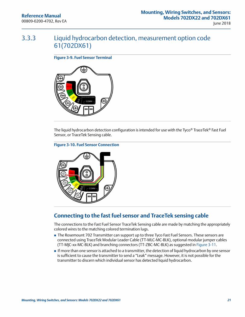
Figure 3-9. Fuel Sensor Terminal
The liquid hydrocarbon detection configuration is intended for use with the Tyco® TraceTek® Fast Fuel Sensor, or TraceTek Sensing cable.
Figure 3-10. Fuel Sensor Connection
Connecting to the fast fuel sensor and TraceTek sensing cableThe connections to the Fast Fuel Sensor TraceTek Sensing cable are made by matching the appropriately colored wires to the matching colored termination lugs.
The Rosemount 702 Transmitter can support up to three Tyco Fast Fuel Sensors. These sensors are connected using TraceTek Modular Leader Cable (TT-MLC-MC-BLK), optional modular jumper cables (TT-MJC-xx-MC-BLK) and branching connectors (TT-ZBC-MC-BLK) as suggested in Figure 3-11.
If more than one sensor is attached to a transmitter, the detection of liquid hydrocarbon by one sensor is sufficient to cause the transmitter to send a “Leak” message. However, it is not possible for the transmitter to discern which individual sensor has detected liquid hydrocarbon.
21Mounting, Wiring Switches, and Sensors: Models 702DX22 and 702DX61

Reference Manual00809-0200-4702, Rev EA
Mounting, Wiring Switches, and Sensors: Models 702DX22 and 702DX61June 2018
Figure 3-11. Fuel Sensor Wiring
A. T-MLC-MC-BLK (leader cable)B. TT-FFS-100 or TT-FFS-250 (Fast Fuel Sensor probe)C. TT-MJC-xx-MC-BLK (optional jumper cable)D. TT-ZBC-xx-MC-BLK (branch connector)
NoteAll part numbers on this page refer to products sold by Tyco Thermo Controls, LLC.
The Rosemount 702 Transmitter can support up to 500 ft. (150 m) of TraceTek hydrocarbon or solvent sensor cable (TT5000 or TT5001 series). The total amount of sensor cable connected to a single transmitter is not to exceed 500 ft. However leader cable, jumper cables (if used) and branch connectors are not included in the 500 ft. limit. See Figure 3-12 for typical configurations.
A
A
B
B
CD
22 Mounting, Wiring Switches, and Sensors: Models 702DX22 and 702DX61

Reference Manual 00809-0200-4702, Rev EA
Mounting, Wiring Switches, and Sensors:Models 702DX22 and 702DX61
June 2018
Figure 3-12. Fuel Sensor Cable Wiring
A. TT-MLC-MC-BLK (leader cable)B. TT5000/TT5001 Sensor cable (up to 500 ft.)C. TT-MET-MC (end termination)D. TT-MJC-xx-MC-BLK (optional jumper cable)E. Up to 500 ft. TT5000 or TT5001 sensor cable (total per transmitter)F. TT-ZBC-xx-MC-BLK (branch connector)
3.4 LCD displayIf an LCD display is ordered, it will be shipped attached to the transmitter.
NoteAn LCD display is not available with measurement option code 61, for liquid hydrocarbon detection.
The optional LCD display can be rotated in 90-degree increments by squeezing the two tabs, pulling out, rotating and snapping back into place.
If the LCD pins are inadvertently removed from the interface board, carefully re-insert the pins before snapping the LCD display back into place.
A
B
C
C
D
E
F
C
23Mounting, Wiring Switches, and Sensors: Models 702DX22 and 702DX61

Reference Manual00809-0200-4702, Rev EA
Mounting, Wiring Switches, and Sensors: Models 702DX22 and 702DX61June 2018
Installing the LCD displayTo install the LCD display, use Figure 3-13 on page 24 and the following instructions:
1. Remove the LCD cover. Do not remove the instrument cover in explosive environments when the circuit is live.
2. Put the four-pin connector into the LCD display, rotate to the desired position and snap into place.
Note the following LCD temperature limits:
Operating: –4 to 175 °F (–20 to 80 °C)Storage: –40 to 185 °F (–40 to 85 °C)
3. Replace the transmitter cover.
NoteOnly use Rosemount Wireless LCD part number: 00753-9004-0002.
Figure 3-13. Optional LCD Display
A. LCD pinsB. LCD displayC. LCD cover
3.5 Grounding the transmitterThe Rosemount 702 Transmitter operates with the housing grounded or floating. Floating systems, however, can cause extra noise that may affect many types of readout devices. If the signal appears noisy or erratic, grounding at a single point may solve the problem. Grounding of the electronics enclosure should be done in accordance with local and national installation codes. Grounding is accomplished through the process connection using the internal or external case grounding terminal.
Determining grounding requirementsEach process installation has different grounding requirements. Use the options recommended by the facility for the specific switch type, or begin with Option 1, which is the most common.
A B C
24 Mounting, Wiring Switches, and Sensors: Models 702DX22 and 702DX61

Reference Manual 00809-0200-4702, Rev EA
Mounting, Wiring Switches, and Sensors:Models 702DX22 and 702DX61
June 2018
Option 1:
1. Connect switch wiring shield to the grounded transmitter housing.
2. Ensure that the transmitter housing is electrically isolated from the switch wiring.
A. Float switch B. Shield ground pointC. Rosemount 702 Transmitter
Option 2:
1. Ground switch wiring shield at the switch.
2. Ensure that the switch wiring and shield are electronically isolated from the transmitter housing.
A. Float switchB. Shield ground pointC. Rosemount 702 Transmitter
NoteAlways use facility recommended wiring practices.
A
B
C
A
B
C
25Mounting, Wiring Switches, and Sensors: Models 702DX22 and 702DX61
Reference Manual00809-0200-4702, Rev EA
Mounting, Wiring Switches, and Sensors: Models 702DX22 and 702DX61June 2018
26 Mounting, Wiring Switches, and Sensors: Models 702DX22 and 702DX61
Reference Manual 00809-0200-4702, Rev EA
Commissioning: Models 702DX22 and 702DX61June 2018
Section 4 Commissioning: Models 702DX22 and 702DX61
Safety messages . . . . . . . . . . . . . . . . . . . . . . . . . . . . . . . . . . . . . . . . . . . . . . . . . . . . . . . . . . . . . . . . . . . . . . page 27Configuring the transmitter to communicate with the wireless network . . . . . . . . . . . . . . . . . . . . . page 28AMS Wireless Configurator . . . . . . . . . . . . . . . . . . . . . . . . . . . . . . . . . . . . . . . . . . . . . . . . . . . . . . . . . . . . . page 28Field Communicator . . . . . . . . . . . . . . . . . . . . . . . . . . . . . . . . . . . . . . . . . . . . . . . . . . . . . . . . . . . . . . . . . . page 28Verifying operation . . . . . . . . . . . . . . . . . . . . . . . . . . . . . . . . . . . . . . . . . . . . . . . . . . . . . . . . . . . . . . . . . . . page 29
4.1 Safety messagesInstructions and procedures in this section may require special precautions to ensure the safety of the personnel performing the operations. Information that potentially raises safety issues is indicated by a warning symbol ( ). Refer to the following safety messages before performing an operation preceded by this symbol.
NoteThe Rosemount™702 Wireless Discrete Transmitter and all other wireless devices should be installed only after the Gateway has been installed and is functioning properly.
Wireless devices should be powered up in order of proximity from the gateway, beginning with the device closest to the Emerson™ Wireless Gateway. This will result in a simpler and faster network installation.
Failure to follow these installation guidelines could result in death or serious injury.
Make sure only qualified personnel perform the installation.
Explosions could result in death or serious injury. Before connecting a Field Communicator in an explosive atmosphere, make sure the instruments are
installed in accordance with intrinsically safe or non-incendive field wiring practices.
Verify that the operating atmosphere of the transmitter is consistent with the appropriate hazardous locations certifications.
Process leaks could result in death or serious injury. Do not remove the switch while in operation.
Install and tighten sensors before applying pressure.
Electrical shock could cause death or serious injury.
Use extreme caution when making contact with the leads and terminals.
27Commissioning: Models 702DX22 and 702DX61

Reference Manual00809-0200-4702, Rev EA
Commissioning: Models 702DX22 and 702DX61 June 2018
4.2 Configuring the transmitter to communicate with the wireless networkIn order to communicate with the Gateway, and ultimately the Information System, the transmitter must be configured to communicate with the wireless network. This step is the wireless equivalent of connecting wires from a transmitter to the information system. Using a Field Communicator or AMS Wireless Configurator, enter the Network ID and Join Key so that they match the Network ID and Join Key of the gateway and other devices in the network. If the Network ID and Join Key are not identical, the Rosemount 702 Transmitter will not communicate with the network. The Network ID and Join Key may be obtained from the Emerson Wireless Gateway on the Setup>Network>Settings page on the web server, shown in Figure 4-1.
Figure 4-1. Gateway Network Settings
4.3 AMS Wireless Configurator Right click on the Rosemount 702 Transmitter and select Configure. When the menu opens, select Join Device to Network and follow the method to enter the Network ID and Join Key.
4.4 Field Communicator The Network ID and Join Key may be changed in the wireless device by using the following Fast Key sequence. Set both Network ID and Join Key.
Function Key Sequence Menu Items
Wireless Setup 2, 1, 1 Network ID, Set Join Key
28 Operation and Maintenance

Reference Manual 00809-0200-4702, Rev EA
Commissioning: Models 702DX22 and 702DX61June 2018
4.5 Verifying operationThere are four ways to verify operation: using the optional local display (LCD), using the Field Communicator, using the Gateway's integrated web interface, or by using AMS Suite Wireless Configurator. If the Rosemount 702 Transmitter was configured with the Network ID and Join Key, and sufficient time has passed, the transmitter will be connected to the network.
TroubleshootingIf the device is not joined to the network after power up, verify the correct configuration of the Network ID and Join Key, and verify that Active Advertising has been enabled on the Gateway. The Network ID and Join Key in the device must match the Network ID and Join Key of the Gateway.
Operating the local displayThe LCD displays the PV and SV values at the configured update rate, but no faster than once every 60 seconds.
Diagnostic button display sequenceMore detailed diagnostic information can be obtained by removing the display cover of the Rosemount 702 Transmitter, and momentarily depressing the “DIAG” button. The LCD will display the diagnostic screens as shown in Figure 4-3.
Press the Diagnostic button to display the TAG, Device ID, Network ID, Network Join Status and Device Status screens.
Figure 4-2. Diagnostic Screen Sequence
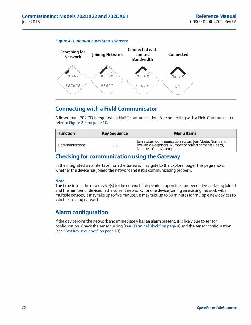
Network join status The chevron-shaped status bar at the top of the screen indicates the progress of the network join process. When the status bar is filled, the device is successfully connected to the wireless network. This is shown, in Figure 4-3 on page 30.
Tag Device ID Network IDNetwork Join
StatusDevice Status
A b c d e
f g h
i d - 1 2
3 4 5 6 7 8
n e t w k
13 0 5 I D
n e t w k
O K
S u p l y
7. 2 1v o l t s
29Commissioning: Models 702DX22 and 702DX61
Reference Manual00809-0200-4702, Rev EA
Commissioning: Models 702DX22 and 702DX61 June 2018
Figure 4-3. Network Join Status Screens
Connecting with a Field CommunicatorA Rosemount 702 DD is required for HART communication. For connecting with a Field Communicator, refer to Figure 2-3 on page 10.
Checking for communication using the GatewayIn the integrated web interface from the Gateway, navigate to the Explorer page. This page shows whether the device has joined the network and if it is communicating properly.
NoteThe time to join the new device(s) to the network is dependent upon the number of devices being joined and the number of devices in the current network. For one device joining an existing network with multiple devices, it may take up to five minutes. It may take up to 60 minutes for multiple new devices to join the existing network.
Alarm configurationif the device joins the network and immediately has an alarm present, it is likely due to sensor configuration. Check the sensor wiring (see “Terminal Block” on page 9) and the sensor configuration (see “Fast Key sequence” on page 13).
Searching for Network
Joining NetworkConnected with
Limited Bandwidth
Connected
Function Key Sequence Menu Items
Communications 3,3Join Status, Communication Status, Join Mode, Number of Available Neighbors, Number of Advertisements Heard, Number of Join Attempts
N E T w K
S R C H N G
n e t w k
N E G O T
n e t w k
L I M - O P
n e t w k
O K
30 Operation and Maintenance

Reference Manual 00809-0200-4702, Rev EA
Commissioning: Models 702DX22 and 702DX61June 2018
Figure 4-4. Gateway Explorer Page
4.5.1 AMS Wireless ConfiguratorWhen the device has joined the network, it will appear in the Device Manager as illustrated below:
TroubleshootingIf the device is not joined to the network after power up, verify the correct configuration of the Network ID and Join Key, and verify that Active Advertising has been enabled on the Gateway. The Network ID and Join Key in the device must match the Network ID and Join Key of the Gateway.
The Network ID and Join Key may be obtained from the Gateway on the Setup>Network>Settings page on the web interface (see Figure 4-4 on page 31). The Network ID and Join Key may be changed in the wireless device by using the following Fast Key sequence.
Function Key Sequence Menu Items
Wireless 2,1,1 Join Device to Network
31Commissioning: Models 702DX22 and 702DX61

Reference Manual00809-0200-4702, Rev EA
Commissioning: Models 702DX22 and 702DX61 June 2018
32 Operation and Maintenance

Reference Manual 00809-0200-4702, Rev EA
Operation and Maintenance:Models 702DX22 and 702DX61
June 2018
Section 5 Operation and Maintenance: Models 702DX22 and 702DX61
Safety Messages . . . . . . . . . . . . . . . . . . . . . . . . . . . . . . . . . . . . . . . . . . . . . . . . . . . . . . . . . . . . . . . . . . . . . . page 33Discrete input from switches and sensors . . . . . . . . . . . . . . . . . . . . . . . . . . . . . . . . . . . . . . . . . . . . . . . . page 34LCD display screen messages . . . . . . . . . . . . . . . . . . . . . . . . . . . . . . . . . . . . . . . . . . . . . . . . . . . . . . . . . . . page 40Replacing the power module . . . . . . . . . . . . . . . . . . . . . . . . . . . . . . . . . . . . . . . . . . . . . . . . . . . . . . . . . . . page 48Service support . . . . . . . . . . . . . . . . . . . . . . . . . . . . . . . . . . . . . . . . . . . . . . . . . . . . . . . . . . . . . . . . . . . . . . . page 49
5.1 Safety MessagesInstructions and procedures in this section may require special precautions to ensure the safety of the personnel performing the operations. Information that potentially raises safety issues is indicated by a warning symbol ( ). Refer to the following safety messages before performing an operation preceded by this symbol.
Failure to follow these installation guidelines could result in death or serious injury.
Make sure only qualified personnel perform the installation.
Explosions could result in death or serious injury. Before connecting a Field Communicator in an explosive atmosphere, make sure the instruments
are installed in accordance with intrinsically safe or non-incendive field wiring practices.
Verify that the operating atmosphere of the transmitter is consistent with the appropriate hazardous locations certifications.
Process leaks could result in death or serious injury. Do not remove the switch while in operation.
Install and tighten sensors before applying pressure.
Electrical shock could cause death or serious injury.
Use extreme caution when making contact with the leads and terminals.
33Operation and Maintenance: Models 702DX22 and 702DX61

Reference Manual00809-0200-4702, Rev EA
Operation and Maintenance: Models 702DX22 and 702DX61June 2018
5.2 Discrete input from switches and sensors
5.2.1 Dry contact inputs, measurement option code 22 (702DX22)
Figure 5-1. Terminal Diagram.
5.2.2 Wireless output specifications
Dual input
The Rosemount™ 702 Wireless Discrete Transmitter will accept the input from one or two single pole single throw switches on inputs S1 and S2. The wireless output of the transmitter will be both a primary variable (PV) and a secondary variable (SV). The PV is determined by the S1 input. The SV is determined by the S2 input. A closed switch drives a TRUE output. An Open switch drives a FALSE output.
NoteAny dry contact input can be inverted by the device, so as to give the opposite effect. This is useful, for instance, if a normally open switch is used to replace a normally closed switch.
Figure 5-2. Single and Dual Input
Single input Dual input
S1
CMN
S2
CMN
S1
CMN
S2
CMN
34 Operation and Maintenance: Models 702DX22 and 702DX61

Reference Manual 00809-0200-4702, Rev EA
Operation and Maintenance:Models 702DX22 and 702DX61
June 2018
Dual input, limit contact logicWhen configured for limit contact logic, the Rosemount 702 Transmitter will accept the input from two single pole single throw switches on inputs S1 and S2, and will use limit contact logic for the determination of the wireless outputs. The following tables describe the wireless outputs available when using limit contact logic.
Figure 5-3. Dual Input, Limit Contacts
Dual input, opposing contact logicWhen configured for Opposing Contact Logic, the Rosemount 702 Transmitter will accept the input from a single pole double throw switch on inputs S1 and S2, and will use opposing contact logic for the determination of the wireless outputs. The following tables describe the wireless outputs available when using opposing contact logic.
Switch input Wireless output Switch input Wireless output
S1 PV S2 SV
Closed TRUE (1.0) Closed TRUE (1.0)
Open FALSE (0.0) Open FALSE (0.0)
Switch inputs Wireless outputs
S1 S2 PV SV
Open Open TRAVEL (0.5) TRAVEL (0.5)
Open Closed FALSE (0.0) FALSE (0.0)
Closed Open TRUE (1.0) TRUE (1.0)
Closed Closed FAULT(NaN) FAULT(NaN)
S1
CMN
S2
CMN
35Operation and Maintenance: Models 702DX22 and 702DX61

Reference Manual00809-0200-4702, Rev EA
Operation and Maintenance: Models 702DX22 and 702DX61June 2018
Figure 5-4. Dual Input, Opposing Contact
5.2.3 Liquid hydrocarbon detection, measurement option code 61 (702DX61)
Figure 5-5. Fuel Sensor Terminal
The Liquid Hydrocarbon Detection configuration is intended for use with the Tyco® TraceTek® Fast Fuel Sensor, or TraceTek Sensing cable.
Switch inputs Wireless outputs
S1 S2 PV SV
Open Open FAULT(NaN) FAULT(NaN)
Open Closed FALSE (0.0) FALSE (0.0)
Closed Open TRUE (1.0) TRUE (1.0)
Closed Closed FAULT(NaN) FAULT(NaN)
S1
CMN
S2
CMN
36 Operation and Maintenance: Models 702DX22 and 702DX61
Reference Manual 00809-0200-4702, Rev EA
Operation and Maintenance:Models 702DX22 and 702DX61
June 2018
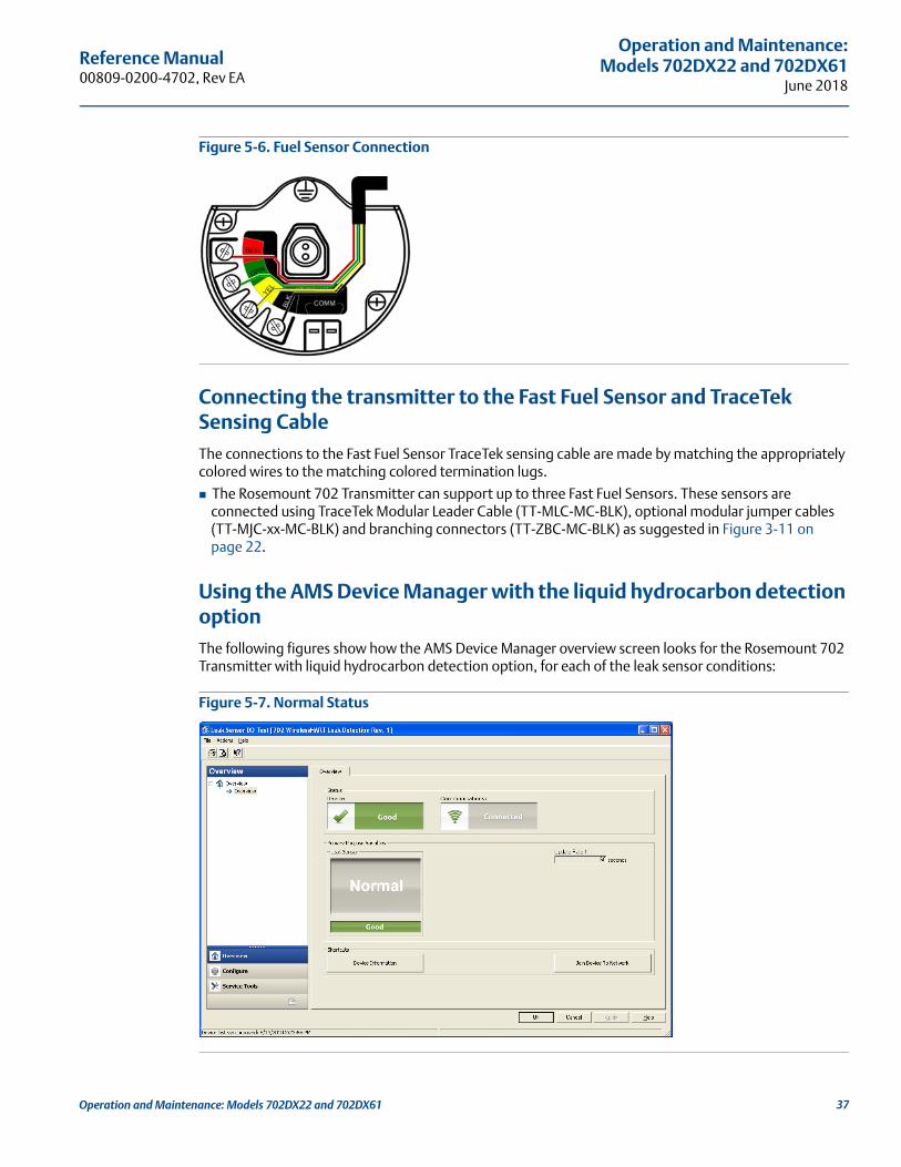
Figure 5-6. Fuel Sensor Connection
Connecting the transmitter to the Fast Fuel Sensor and TraceTek Sensing CableThe connections to the Fast Fuel Sensor TraceTek sensing cable are made by matching the appropriately colored wires to the matching colored termination lugs.
The Rosemount 702 Transmitter can support up to three Fast Fuel Sensors. These sensors are connected using TraceTek Modular Leader Cable (TT-MLC-MC-BLK), optional modular jumper cables (TT-MJC-xx-MC-BLK) and branching connectors (TT-ZBC-MC-BLK) as suggested in Figure 3-11 on page 22.
Using the AMS Device Manager with the liquid hydrocarbon detection optionThe following figures show how the AMS Device Manager overview screen looks for the Rosemount 702 Transmitter with liquid hydrocarbon detection option, for each of the leak sensor conditions:
Figure 5-7. Normal Status
37Operation and Maintenance: Models 702DX22 and 702DX61

Reference Manual00809-0200-4702, Rev EA
Operation and Maintenance: Models 702DX22 and 702DX61June 2018
Figure 5-8. Leak Status
Figure 5-9. Leak Sensor Not Connected Status
Table 5-1. Liquid Hydrocarbon Detection Interface, for Modbus® mapping
PV SV Description/interpretation
1.0 1.0 Normal condition, no leak detected, sensor status good
0.0 1.0 or 0.0 Leak detected, sensor status good
1.0 0.0 Sensor Not Connected, Assume Leak, take appropriate action
38 Operation and Maintenance: Models 702DX22 and 702DX61
Reference Manual 00809-0200-4702, Rev EA
Operation and Maintenance:Models 702DX22 and 702DX61
June 2018
Table 5-1 describes use of the Rosemount 702 Transmitter for hydrocarbon detection in other communications protocols such as Modbus or OPC. It is imperative that both PV and SV be mapped to the host system so as to make a good interpretation of the condition and status of the leak detector.
NoteIt is imperative that both PV and SV be mapped to the host system so that the diagnostic information on the sensor status is captured.
In addition, system considerations must be observed to ensure that the device is still connected to the wireless network and reporting values. On an Emerson Wireless Gateway, this can be done by referring to the parameter: PV_HEALTHY. PV_HEALTHY has a “True” state when the device is on the network and its updates are current, not late or stale, and the device is functioning properly. A “False” state of PV_HEALTHY means that the device is either off of the network, the data updates are not current, or that there is a malfunction of the device (such as an electronics failure). In the case of a “False” state of PV_HEALTHY, it is recommended to assume that the device is not connected to the network and to take appropriate action.
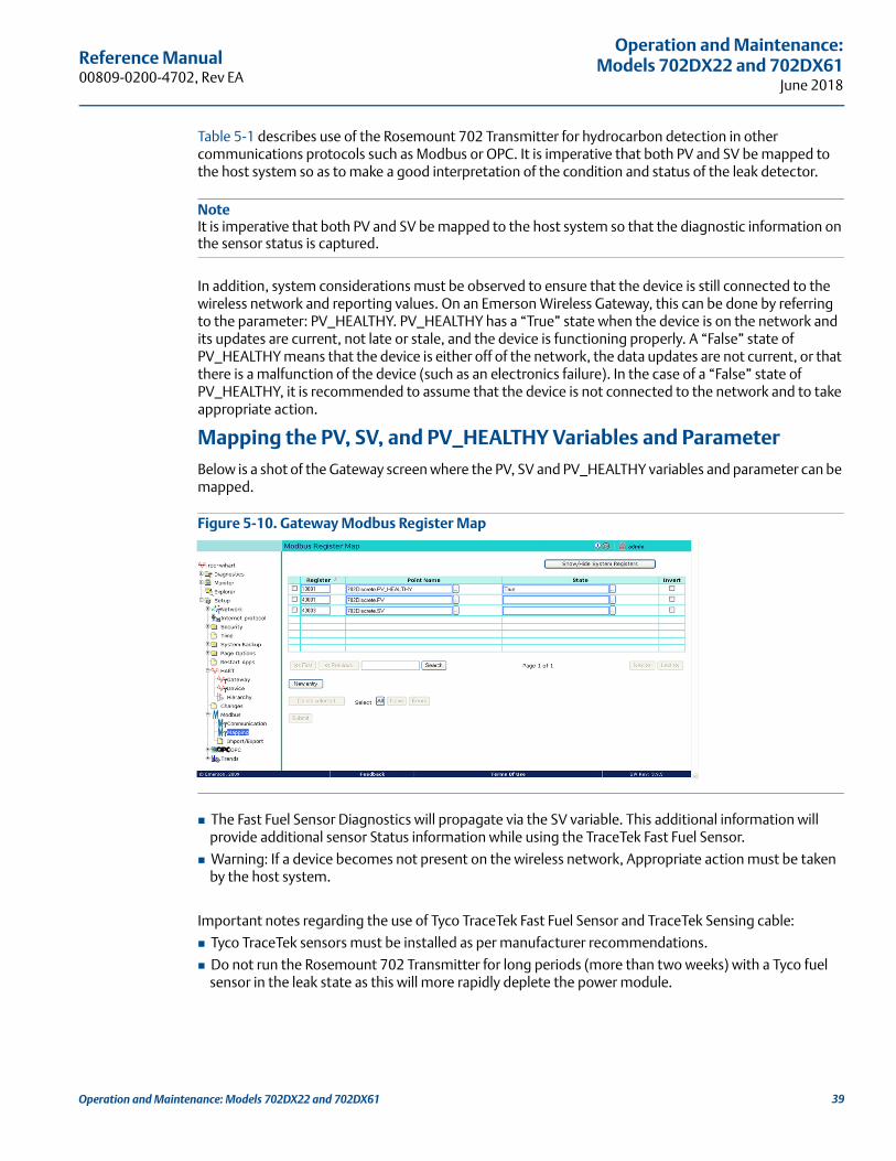
Mapping the PV, SV, and PV_HEALTHY Variables and ParameterBelow is a shot of the Gateway screen where the PV, SV and PV_HEALTHY variables and parameter can be mapped.
Figure 5-10. Gateway Modbus Register Map
The Fast Fuel Sensor Diagnostics will propagate via the SV variable. This additional information will provide additional sensor Status information while using the TraceTek Fast Fuel Sensor.
Warning: If a device becomes not present on the wireless network, Appropriate action must be taken by the host system.
Important notes regarding the use of Tyco TraceTek Fast Fuel Sensor and TraceTek Sensing cable:
Tyco TraceTek sensors must be installed as per manufacturer recommendations.
Do not run the Rosemount 702 Transmitter for long periods (more than two weeks) with a Tyco fuel sensor in the leak state as this will more rapidly deplete the power module.
39Operation and Maintenance: Models 702DX22 and 702DX61
Reference Manual00809-0200-4702, Rev EA
Operation and Maintenance: Models 702DX22 and 702DX61June 2018
5.3 LCD display screen messages
NoteDry Contact Inputs only, Measurement Option Code 22. LCD is not available for Liquid Hydrocarbon Detection, Measurement Option Code 61.
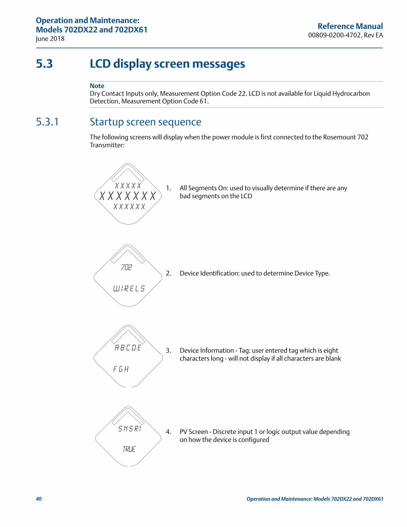
5.3.1 Startup screen sequenceThe following screens will display when the power module is first connected to the Rosemount 702 Transmitter:
1. All Segments On: used to visually determine if there are any bad segments on the LCD
2. Device Identification: used to determine Device Type.
3. Device Information - Tag: user entered tag which is eight characters long - will not display if all characters are blank
4. PV Screen - Discrete input 1 or logic output value depending on how the device is configured
X X X X X
X X X X x x xx x x x x x
702
W I r e l s
A b c d e
f g h
s n s r1
True
40 Operation and Maintenance: Models 702DX22 and 702DX61

Reference Manual 00809-0200-4702, Rev EA
Operation and Maintenance:Models 702DX22 and 702DX61
June 2018
5. SV Screen - Discrete input 2
6. TV Screen - feature board temperature value
7. QV Screen - voltage reading at the power module terminals
8. Alert Screen - at least one alert is present - this screen will not display if no alerts are present
S N S R 2
True
D E V
2 5. 2 5d e g c
S u p l y
7. 2 1v o l t s
a l e r t
p r e s n t
41Operation and Maintenance: Models 702DX22 and 702DX61

Reference Manual00809-0200-4702, Rev EA
Operation and Maintenance: Models 702DX22 and 702DX61June 2018
5.3.2 Diagnostic button screen sequenceThe following five screens will display when the device is operating properly and the Diagnostic Button has been pressed:
1. Device Information - Tag: user entered tag which is eight characters long - will not display if all characters are blank
2. Device Identification: used to determine Device ID
3. Network ID: assuming the device has the correct join key, this ID tells the user what network the device can connect with
4. Network Connection Status: the device has joined a network and has been fully configured and has multiple parents
5. Supply Voltage: voltage reading at the power module terminals
A b c d e
f g h
i d - X X
X X X X X X
n e t w k
13 0 5 I D
n e t w k
O K
S u p l y
7. 2 1v o l t s
42 Operation and Maintenance: Models 702DX22 and 702DX61

Reference Manual 00809-0200-4702, Rev EA
Operation and Maintenance:Models 702DX22 and 702DX61
June 2018
5.3.3 Network connection status screensThese screens display the network status of the device. Only one will be shown in the fourth position of the diagnostic button screen sequence.
1. Diagnostic Button Screen 4.1: the device is attempting to start the radio
2. Diagnostic Button Screen 4.2: the device has just restarted
3. Diagnostic Button Screen 4.3: the device is starting to join the process
4. Diagnostic Button Screen 4.4: the device is in a disconnected state and requires a “Force Join” command to join the network
5. Diagnostic Button Screen 4.5: the device is searching for the Network
n e t w k
u n k n w n
n e t w k
I N I T
n e t w k
i d l e
n e t w k
D I S C N T
N E T w K
S R C H N G
43Operation and Maintenance: Models 702DX22 and 702DX61

Reference Manual00809-0200-4702, Rev EA
Operation and Maintenance: Models 702DX22 and 702DX61June 2018
6. Diagnostic Button Screen 4.6: the device is attempting to join a network
7. Diagnostic Button Screen 4.7: the device is connected to the Network, but is in a “Quarantined” state
8. Diagnostic Button Screen 4.8: the device is joined and operational, but is running with limited bandwidth for sending periodic data
9. Diagnostic Button Screen 4.9: the device has joined a network and has been fully configured and has multiple parents
n e t w k
N E G O T
n e t w k
c o n e c t
n e t w k
L I M - O P
n e t w k
O K
44 Operation and Maintenance: Models 702DX22 and 702DX61
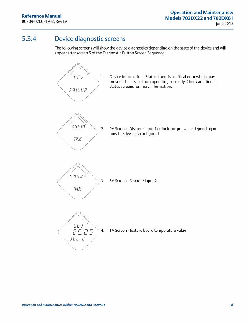
Reference Manual 00809-0200-4702, Rev EA
Operation and Maintenance:Models 702DX22 and 702DX61
June 2018
5.3.4 Device diagnostic screensThe following screens will show the device diagnostics depending on the state of the device and will appear after screen 5 of the Diagnostic Button Screen Sequence.
1. Device Information - Status: there is a critical error which may prevent the device from operating correctly. Check additional status screens for more information.
2. PV Screen - Discrete input 1 or logic output value depending on how the device is configured
3. SV Screen - Discrete input 2
4. TV Screen - feature board temperature value
D E V
f A i l u r
s n s r1
True
S N S R 2
True
D E V
2 5. 2 5d e g c
45Operation and Maintenance: Models 702DX22 and 702DX61
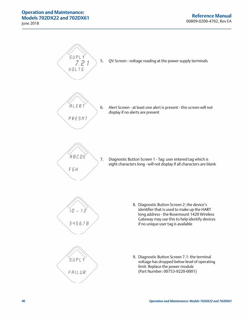
Reference Manual00809-0200-4702, Rev EA
Operation and Maintenance: Models 702DX22 and 702DX61June 2018
5. QV Screen - voltage reading at the power supply terminals
6. Alert Screen - at least one alert is present - this screen will not display if no alerts are present
7. Diagnostic Button Screen 1 - Tag: user entered tag which is eight characters long - will not display if all characters are blank
8. Diagnostic Button Screen 2: the device’s identifier that is used to make up the HART long address - the Rosemount 1420 Wireless Gateway may use this to help identify devices if no unique user tag is available
9. Diagnostic Button Screen 7.1: the terminal voltage has dropped below level of operating limit. Replace the power module (Part Number: 00753-9220-0001)
S u p l y
7. 2 1v o l t s
a l e r t
p r e s n t
A b c d e
f g h
i d - 1 2
3 4 5 6 7 8
s u p l y
f a i l u r
46 Operation and Maintenance: Models 702DX22 and 702DX61
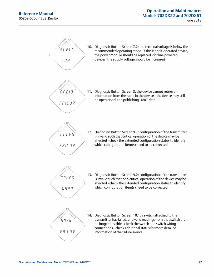
Reference Manual 00809-0200-4702, Rev EA
Operation and Maintenance:Models 702DX22 and 702DX61
June 2018
10. Diagnostic Button Screen 7.2: the terminal voltage is below the recommended operating range - if this is a self-operated device, the power module should be replaced - for line powered devices, the supply voltage should be increased
11. Diagnostic Button Screen 8: the device cannot retrieve information from the radio in the device - the device may still be operational and publishing HART data
12. Diagnostic Button Screen 9.1: configuration of the transmitter is invalid such that critical operation of the device may be affected - check the extended configuration status to identify which configuration item(s) need to be corrected
13. Diagnostic Button Screen 9.2: configuration of the transmitter is invalid such that non-critical operation of the device may be affected - check the extended configuration status to identify which configuration item(s) need to be corrected
14. Diagnostic Button Screen 10.1: a switch attached to the transmitter has failed, and valid readings from that switch are no longer possible - check the switch and switch wiring connections - check additional status for more detailed information of the failure source
s u p l y
l o w
r a d i o
f a i l u r
c o n f g
f a i l u r
c o n f g
w a r n
s n s r
f a i l u r
47Operation and Maintenance: Models 702DX22 and 702DX61

Reference Manual00809-0200-4702, Rev EA
Operation and Maintenance: Models 702DX22 and 702DX61June 2018
NoteUse Rosemount wireless LCD display part number: 00753-9004-0002.
5.4 Replacing the power moduleExpected power module life is ten years at reference conditions.(1)
When the power module needs to be replaced, remove the power module cover and the depleted power module. Replace the power module with a new Black Power Module, SmartPower™ Solutions model number 701PBKKF (part number 00753-9220-0001). Then replace the cover and tighten it to specification. Always ensure a proper seal so that metal touches metal, but do not overtighten.
Handling the power poduleThe Black Power Module with the wireless unit contains two “C” size primary lithium/thionyl chloride batteries. Each battery contains approximately 2.5 grams of lithium, for a total of 5 grams in each pack. Under normal conditions, the battery materials are self-contained and are not reactive as long as the batteries and the battery pack integrity are maintained. Care should be taken to prevent thermal, electrical or mechanical damage. Contacts should be protected to prevent premature discharge.
Use caution when handling the power module, it may be damaged if dropped from heights in excess of 20 ft.
Battery hazards remain when cells are discharged.
Environmental considerationsAs with any battery, local environmental rules and regulations should be consulted for proper management of spent batteries. If no specific requirements exist, recycling through a qualified recycler is encouraged. Consult the materials safety data sheet for battery specific information.
Shipping considerationsThe unit was shipped to you without the power module installed. Remove the power module prior to shipping.
Each power module contains two “C” size primary lithium batteries. Primary lithium batteries are regulated in transportation by the U.S. Department of Transportation, and are also covered by International Air Transport Association (IATA), International Civil Aviation Organization (ICAO), and European Ground Transportation of Dangerous Goods (ARD). It is the responsibility of the shipper to ensure compliance with these or any other local requirements. Consult current regulations and requirements before shipping.
1. Reference conditions are 70 °F (21 °C), wireless update of once per minute, and routing data for three additional network devices.
48 Operation and Maintenance: Models 702DX22 and 702DX61

Reference Manual 00809-0200-4702, Rev EA
Operation and Maintenance:Models 702DX22 and 702DX61
June 2018
5.5 Service supportTo expedite the return process outside of North America, contact your Emerson™ representative,
Within the United States, call the Emerson Response Center toll-free number 1 800 654 7768. The center, which is available 24 hours a day, will assist you with any needed information or materials.
The center will ask for product model and serial numbers, and will provide a Return Material Authorization (RMA) number. The center will also ask for the process material to which the product was last exposed.
Individuals who handle products exposed to a hazardous substance can avoid injury if they are informed of, and understand, the hazard. If the product being returned was exposed to a hazardous substance as defined by OSHA, a copy of the required Material Safety Data Sheet (MSDS) for each hazardous substance identified must be included with the returned goods.
49Operation and Maintenance: Models 702DX22 and 702DX61

50
Reference Manual00809-0200-4702, Rev EA
Operation and Maintenance: Models 702DX22 and 702DX61June 2018
Operation and Maintenance: Models 702DX22 and 702DX61
Reference Manual 00809-0200-4702, Rev EA
Configuration: Models 702DX32 and 702DX42June 2018
Section 6 Configuration: Models 702DX32 and 702DX42
Safety messages . . . . . . . . . . . . . . . . . . . . . . . . . . . . . . . . . . . . . . . . . . . . . . . . . . . . . . . . . . . . . . . . . . . . . . page 51Discrete channel configuration . . . . . . . . . . . . . . . . . . . . . . . . . . . . . . . . . . . . . . . . . . . . . . . . . . . . . . . . . page 52Device network configuration . . . . . . . . . . . . . . . . . . . . . . . . . . . . . . . . . . . . . . . . . . . . . . . . . . . . . . . . . . page 52HART menu tree . . . . . . . . . . . . . . . . . . . . . . . . . . . . . . . . . . . . . . . . . . . . . . . . . . . . . . . . . . . . . . . . . . . . . . page 55Removing the power module . . . . . . . . . . . . . . . . . . . . . . . . . . . . . . . . . . . . . . . . . . . . . . . . . . . . . . . . . . . page 58
6.1 Safety messagesInstructions and procedures in this section may require special precautions to ensure the safety of the personnel performing the operations. Information that potentially raises safety issues is indicated by a warning symbol ( ). Refer to the following safety messages before performing an operation preceded by this symbol.
Failure to follow these installation guidelines could result in death or serious injury.
Only qualified personnel should perform the installation.
Explosions could result in death or serious injury. Before connecting a Field Communicator in an explosive atmosphere, make sure that the
instruments are installed in accordance with intrinsically safe or non-incendive field wiring practices.
Verify that the operating atmosphere of the transmitter is consistent with the appropriate hazardous locations certifications.
Process leaks could result in death or serious injury. Do not remove the switch while in operation.
Install and tighten switches before applying pressure.
Electrical shock could cause death or serious injury.
Use extreme caution when making contact with the leads and terminals.
51Configuration: Models 702DX32 and 702DX42
Reference Manual00809-0200-4702, Rev EA
Configuration: Models 702DX32 and 702DX42June 2018
6.1.1 Ensuring proper switch connectionsThe Rosemount™ 702 Wireless Discrete Transmitter is compatible with a number of simple switches. When ordered in the optional configuration for Liquid Hydrocarbon Detection, option code 61, the transmitter is compatible with Tyco® TraceTek® Fast Fuel Sensors and TraceTek sensing cable. Figure 6-1 on page 53 shows the correct input connections to the switch terminals on the transmitter. To ensure a proper switch connection, anchor the switch lead wires into the appropriate compression terminals and tighten the screws.
Switch leadsIf the switch is installed in a high-voltage environment and a fault condition or installation error occurs, the sensor leads and transmitter terminals could carry lethal voltage. Use extreme caution when making contact with the leads and terminals.
Wiring the sensor and power supply to the transmitterUse the following steps to wire the sensor and power supply to the transmitter:
1. Remove the transmitter enclosure cover (if applicable).
2. Attach the sensor leads according to the wiring diagram Figure 2-2 on page 10.
3. Connect the power module.
4. Verify the connection by viewing the LCD display.
5. Replace the cover and tighten (if applicable).
6.2 Discrete channel configurationRemove the power module-side housing cover to expose the terminal block and HART communication terminals, then connect the power module to power the unit for configuration.
The Rosemount 702 Transmitter will receive any HART Communication from a Field Communicator, or AMS Wireless Configurator. When using a Field Communicator, any configuration changes must be sent to the transmitter using the Send key (F2). AMS Wireless Configurator configuration changes are implemented when the Apply button is clicked.
Configuring on the bench with a HART modem
AMS Wireless Configurator is capable of connecting to devices directly, using a HART® modem, or with the Gateway. When configuring on the bench with a HART modem, double click the device icon, then choose the Configure/Setup tab (or right click and select Configure/Setup). Configure the device settings using the Direct Connection menu. When configuring with the Gateway, double click the device icon then choose the Configure/Setup tab (or right click and select Configure/Setup). Configure the device settings using the Wireless Connection menu.
To check or change discrete channel configuration using a Field Communicator, enter the following Fast Key Sequence: 2, 2, 2.
6.3 Device network configurationTo communicate with the Gateway, and ultimately the Information System, the transmitter must be configured to communicate with the wireless network.
52 Configuration: Models 702DX32 and 702DX42
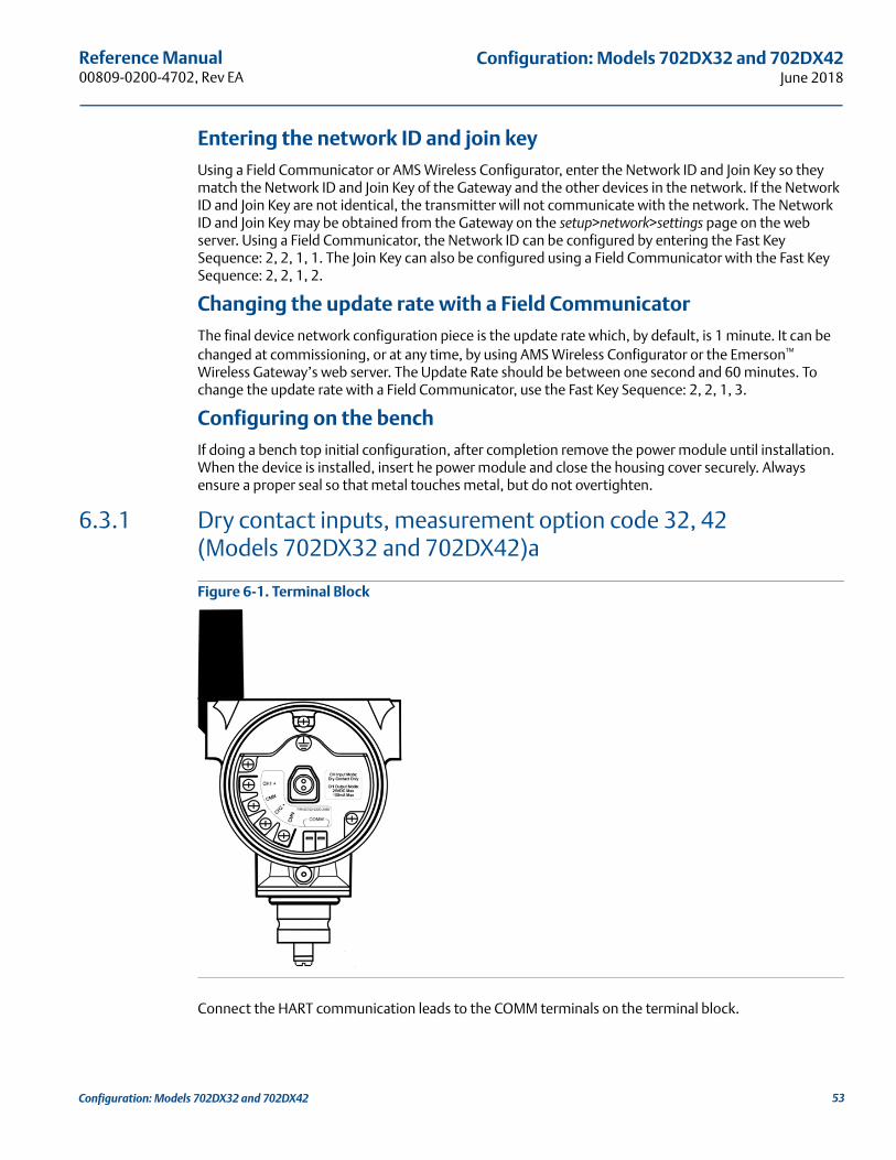
Reference Manual 00809-0200-4702, Rev EA
Configuration: Models 702DX32 and 702DX42June 2018
Entering the network ID and join keyUsing a Field Communicator or AMS Wireless Configurator, enter the Network ID and Join Key so they match the Network ID and Join Key of the Gateway and the other devices in the network. If the Network ID and Join Key are not identical, the transmitter will not communicate with the network. The Network ID and Join Key may be obtained from the Gateway on the setup>network>settings page on the web server. Using a Field Communicator, the Network ID can be configured by entering the Fast Key Sequence: 2, 2, 1, 1. The Join Key can also be configured using a Field Communicator with the Fast Key Sequence: 2, 2, 1, 2.
Changing the update rate with a Field CommunicatorThe final device network configuration piece is the update rate which, by default, is 1 minute. It can be changed at commissioning, or at any time, by using AMS Wireless Configurator or the Emerson™ Wireless Gateway’s web server. The Update Rate should be between one second and 60 minutes. To change the update rate with a Field Communicator, use the Fast Key Sequence: 2, 2, 1, 3.
Configuring on the benchIf doing a bench top initial configuration, after completion remove the power module until installation. When the device is installed, insert he power module and close the housing cover securely. Always ensure a proper seal so that metal touches metal, but do not overtighten.
6.3.1 Dry contact inputs, measurement option code 32, 42 (Models 702DX32 and 702DX42)a
Figure 6-1. Terminal Block
Connect the HART communication leads to the COMM terminals on the terminal block.
53Configuration: Models 702DX32 and 702DX42

Reference Manual00809-0200-4702, Rev EA
Configuration: Models 702DX32 and 702DX42June 2018
Figure 6-2. Field Communicator Connections
For HART communication, a Rosemount 702 DD is required.
COMM
P/N 00753-9200-0020
1
2
3
4
54 Configuration: Models 702DX32 and 702DX42

Reference Manual 00809-0200-4702, Rev EA
Configuration: Models 702DX32 and 702DX42June 2018
6.4 HART menu treeFor ease of operation, changing setup, such as switch type, can be completed in several locations.
Figure 6-3. Overview Home1 Overview2 Configure3 Service Tools
Overview1 Device Status 2 Communication Status 3 Channel 1 Value4 Channel 1 Status5 Channel 1 count6 Channel 1 Direction7 Channel 2 Value8 Channel 2 Status9 Channel 2 Count10 Channel 2 Direction11 Update Rate 112 Update Rate 213 Update Rate 314 DD Revision15 Device Information Device Information
1 Identification2 Revisions3 Radio4 Device Options
Identification1 Device Image2 Tag3 Long Tag4 Model5 Serial Number6 Date7 Descriptor8 Message9 Model Number I10 Model Number II11 Model Number III
Device Status1 Active Alerts
Active Alerts1 Good- only if no alerts2 Failed - Fix Now3 Advisory4 Maintenance – Fix Soon
Good- only if no alerts1 No Active Alerts
Failed - Fix Now1 Electronics Failure2 Input/Output Failure3 Radio Failure4 Supply Voltage Failure
Maintenance – Fix Soon1 Sensor Degraded2 Terminal Temperature Out of Range3 Calibration Error4 Primary Out of Limits5 Sensor Out of Range6 Analog Output Saturated7 Analog Output Fixed
Advisory1 Electronics Warning2 Electronics Temperature has Exceeded Limits3 Module Temperature has Exceeded Limits4 Supply Voltage Low
Device Options1 Measurement Option
Revisions1 HART2 Field Device3 Software4 Hardware5 DD
Radio1 Manufacturer2 Device Type3 Device Revision4 Software Revision5 Hardware Revision6 Transmit Power Level7 Minimum Broadcast Update Rate
5 Security
Security1 Write Protect2 Lock Status3 Over the Air Upgrade
55Configuration: Models 702DX32 and 702DX42

Reference Manual00809-0200-4702, Rev EA
Configuration: Models 702DX32 and 702DX42June 2018
Figure 6-4. ConfigureHome1 Overview2 Configure3 Service Tools
Configure1 Guided Setup2 Manual Setup
Guided Setup1 Join Device To Network 2 Configure Update Rate 3 Configure Discrete Channels 4 Configure Device Display5 Basic Setup
Manual Setup1 Wireless2 Discrete Channel3 Display4 HART5 Security6 Device Temperature7 Device Information8 Power
Wireless1 Network Id2 Join Device To Network 3 Broadcast Information
Broadcast Information1 Configure Advanced Broadcasting (Method)
Discrete Channel1 Application Type2 Channel 1 Direction3 Channel 1 Status4 Channel 2 Direction5 Channel 2 Status6 Setup Channel 17 Setup Channel 2
Setup Channel 11 Channel 1 Direction2 Channel 1 Status3 Channel 1 Count 4 Logic Option5 Count Rollover Value6 Reported Value7 Fault State Option8 Fault State Value9 Fault State Time
Setup Channel 21 Channel 2 Direction2 Channel 2 Status3 Channel 2 Count 4 Logic Option5 Count Rollover Value6 Reported Value7 Fault State Option8 Fault State Value9 Fault State Time
Device Temperature1 Electronics Temperature2 Electronics Temperature Status3 Unit 4 Maximum5 Minimum
Device Information1 Tag2 Long Tag3 Descriptor4 Message5 Date6 Country7 SI Unit Control
Display1 Display Mode2 Display Item
HART1 Measurement and Status Log2 Variable Reporting3 Primary Variable, PV4 2nd Variable, SV5 3rd Variable, TV6 4th Variable, QV7 Configure Data History
Security1 Write Protect2 Lock Status3 Lock/Unlock4 Over the Air Upgrade
Power1 Power Mode2 Power Source
56 Configuration: Models 702DX32 and 702DX42
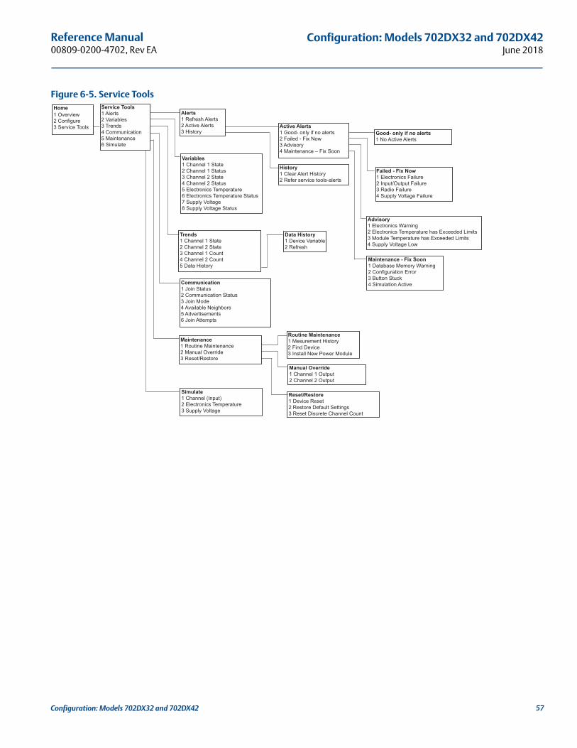
Reference Manual 00809-0200-4702, Rev EA
Configuration: Models 702DX32 and 702DX42June 2018
Figure 6-5. Service ToolsHome1 Overview2 Configure3 Service Tools
Service Tools1 Alerts2 Variables3 Trends4 Communication5 Maintenance6 Simulate
Alerts1 Refresh Alerts2 Active Alerts3 History
Active Alerts1 Good- only if no alerts2 Failed - Fix Now3 Advisory4 Maintenance – Fix Soon
Good- only if no alerts1 No Active Alerts
Failed - Fix Now1 Electronics Failure2 Input/Output Failure3 Radio Failure4 Supply Voltage Failure
Variables1 Channel 1 State2 Channel 1 Status3 Channel 2 State4 Channel 2 Status5 Electronics Temperature6 Electronics Temperature Status7 Supply Voltage8 Supply Voltage Status
Communication1 Join Status2 Communication Status3 Join Mode4 Available Neighbors5 Advertisements6 Join Attempts
Maintenance1 Routine Maintenance2 Manual Override3 Reset/Restore
Simulate1 Channel (Input)2 Electronics Temperature3 Supply Voltage
Advisory1 Electronics Warning2 Electronics Temperature has Exceeded Limits3 Module Temperature has Exceeded Limits4 Supply Voltage Low
Maintenance - Fix Soon1 Database Memory Warning2 Configuration Error3 Button Stuck4 Simulation Active
History1 Clear Alert History2 Refer service tools-alerts
Routine Maintenance1 Mesurement History2 Find Device 3 Install New Power Module
Reset/Restore1 Device Reset2 Restore Default Settings 3 Reset Discrete Channel Count
Manual Override1 Channel 1 Output2 Channel 2 Output
Trends1 Channel 1 State2 Channel 2 State3 Channel 1 Count4 Channel 2 Count5 Data History
Data History1 Device Variable2 Refresh
57Configuration: Models 702DX32 and 702DX42
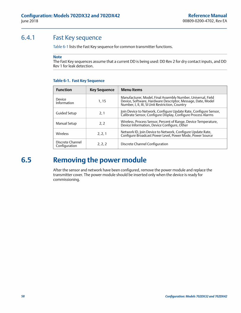
Reference Manual00809-0200-4702, Rev EA
Configuration: Models 702DX32 and 702DX42June 2018
6.4.1 Fast Key sequenceTable 6-1 lists the Fast Key sequence for common transmitter functions.
NoteThe Fast Key sequences assume that a current DD is being used: DD Rev 2 for dry contact inputs, and DD Rev 1 for leak detection.
6.5 Removing the power moduleAfter the sensor and network have been configured, remove the power module and replace the transmitter cover. The power module should be inserted only when the device is ready for commissioning.
Table 6-1. Fast Key Sequence
Function Key Sequence Menu Items
Device Information 1, 15
Manufacturer, Model, Final Assembly Number, Universal, Field Device, Software, Hardware Descriptor, Message, Date, Model Number, I, II, III, SI Unit Restriction, Country
Guided Setup 2, 1 Join Device to Network, Configure Update Rate, Configure Sensor, Calibrate Sensor, Configure Display, Configure Process Alarms
Manual Setup 2, 2 Wireless, Process Sensor, Percent of Range, Device Temperature, Device Information, Device Configure, Other
Wireless 2, 2, 1 Network ID, Join Device to Network, Configure Update Rate, Configure Broadcast Power Level, Power Mode, Power Source
Discrete Channel Configuration 2, 2, 2 Discrete Channel Configuration
58 Configuration: Models 702DX32 and 702DX42

Reference Manual 00809-0200-4702, Rev EA
Mounting, Wiring Switches, and Output Circuits:Models 702DX32 and 702DX42
June 2018
Section 7 Mounting, Wiring Switches, and Output Circuits: Models 702DX32 and 702DX42
Safety messages . . . . . . . . . . . . . . . . . . . . . . . . . . . . . . . . . . . . . . . . . . . . . . . . . . . . . . . . . . . . . . . . . . . . . . page 59Installing the transmitter . . . . . . . . . . . . . . . . . . . . . . . . . . . . . . . . . . . . . . . . . . . . . . . . . . . . . . . . . . . . . . page 60Wiring switches and sensors . . . . . . . . . . . . . . . . . . . . . . . . . . . . . . . . . . . . . . . . . . . . . . . . . . . . . . . . . . . page 63LCD display . . . . . . . . . . . . . . . . . . . . . . . . . . . . . . . . . . . . . . . . . . . . . . . . . . . . . . . . . . . . . . . . . . . . . . . . . . page 70Grounding the transmitter . . . . . . . . . . . . . . . . . . . . . . . . . . . . . . . . . . . . . . . . . . . . . . . . . . . . . . . . . . . . . page 71
7.1 Safety messagesInstructions and procedures in this section may require special precautions to ensure the safety of the personnel performing the operations. Information that potentially raises safety issues is indicated by a warning symbol ( ). Refer to the following safety messages before performing an operation preceded by this symbol.
Failure to follow these installation guidelines could result in death or serious injury.
Only qualified personnel should perform the installation.
Explosions could result in death or serious injury. Before connecting a Field Communicator in an explosive atmosphere, make sure that the
instruments are installed in accordance with intrinsically safe or non-incendive field wiring practices.
Verify that the operating atmosphere of the transmitter is consistent with the appropriate hazardous locations certifications.
Process leaks could result in death or serious injury. Do not remove the switch while in operation.
Install and tighten switches before applying pressure.
Electrical shock could cause death or serious injury. Use extreme caution when making contact with the leads and terminals.
This device complies with Part 15 of the FCC Rules. Operation is subject to the following conditions: This device may not cause harmful interference. This device must accept any interference received, including interference that may cause undesired operation.
This device must be installed to ensure a minimum antenna separation distance of 20 cm from all persons.
59Mounting, Wiring Switches, and Output Circuits: Models 702DX32 and 702DX42
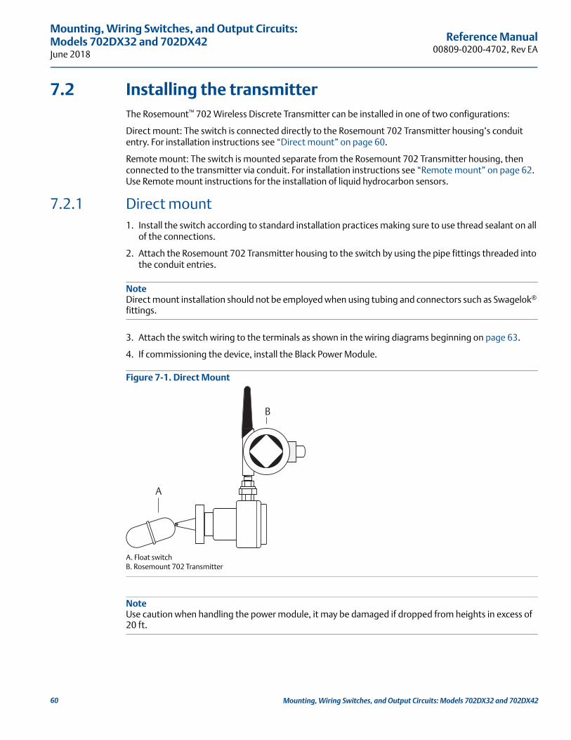
Reference Manual00809-0200-4702, Rev EA
Mounting, Wiring Switches, and Output Circuits: Models 702DX32 and 702DX42June 2018
7.2 Installing the transmitterThe Rosemount™ 702 Wireless Discrete Transmitter can be installed in one of two configurations:
Direct mount: The switch is connected directly to the Rosemount 702 Transmitter housing’s conduit entry. For installation instructions see “Direct mount” on page 60.
Remote mount: The switch is mounted separate from the Rosemount 702 Transmitter housing, then connected to the transmitter via conduit. For installation instructions see “Remote mount” on page 62. Use Remote mount instructions for the installation of liquid hydrocarbon sensors.
7.2.1 Direct mount1. Install the switch according to standard installation practices making sure to use thread sealant on all
of the connections.
2. Attach the Rosemount 702 Transmitter housing to the switch by using the pipe fittings threaded into the conduit entries.
NoteDirect mount installation should not be employed when using tubing and connectors such as Swagelok® fittings.
3. Attach the switch wiring to the terminals as shown in the wiring diagrams beginning on page 63.
4. If commissioning the device, install the Black Power Module.
Figure 7-1. Direct Mount
A. Float switchB. Rosemount 702 Transmitter
NoteUse caution when handling the power module, it may be damaged if dropped from heights in excess of 20 ft.
A
B
60 Mounting, Wiring Switches, and Output Circuits: Models 702DX32 and 702DX42

Reference Manual 00809-0200-4702, Rev EA
Mounting, Wiring Switches, and Output Circuits:Models 702DX32 and 702DX42
June 2018
NoteWireless devices should only be powered up after the Emerson™ Wireless Gateway, in order of proximity from the Gateway beginning with the closest device. This results in a simpler and faster network installation.
Figure 7-2. Power Module Installation
5. Close the housing cover and tighten to safety specifications. Always ensure a proper seal by installing the electronic housing covers so that metal touches metal, but do not overtighten.
6. The antenna should be positioned vertically, typically straight up but the antenna may also be pointed straight down, as shown in Figure 7-3 on page 61.
Figure 7-3. Antenna Positioning
Possible antenna rotation shown.Antenna rotation allows for bestinstallation practices in anyconfiguration.
61Mounting, Wiring Switches, and Output Circuits: Models 702DX32 and 702DX42

Reference Manual00809-0200-4702, Rev EA
Mounting, Wiring Switches, and Output Circuits: Models 702DX32 and 702DX42June 2018
7.2.2 Remote mount1. Install the switch according to standard installation practices being sure to use thread sealant on all of
the connections.
2. Run wiring (and conduit, if necessary) from the switch to the Rosemount 702 Transmitter.
3. Pull the wiring through the threaded conduit entry.
4. Attach the switch wiring to the terminals as shown in the wiring diagrams beginning on page 63.
5. If commissioning the transmitter, connect the Black Power Module as shown in Figure 7-2 on page 61.
Figure 7-4. Remote Mount
A. Float switchB. Rosemount 702 Transmitter
NoteUse caution when handling the power module, it may be damaged if dropped from heights in excess of 20 ft.
NoteWireless devices should only be powered up after the Gateway, in order of proximity from the Gateway beginning with the closest device. This results in a simpler and faster network installation.
6. Close the housing cover and tighten to safety specifications. Always ensure a proper seal by installing the electronic housing covers so that metal touches metal, but do not overtighten.
7. The antenna should be positioned vertically, typically straight up but the antenna may also be pointed straight down, as shown in Figure 7-3 on page 61.
A
B
62 Mounting, Wiring Switches, and Output Circuits: Models 702DX32 and 702DX42

Reference Manual 00809-0200-4702, Rev EA
Mounting, Wiring Switches, and Output Circuits:Models 702DX32 and 702DX42
June 2018
7.3 Wiring switches and sensors
7.3.1 Dry contact inputs, measurement option code 32, 42 (702DX32, 702DX42)
Terminal blockThe Rosemount 702 Transmitter has a pair of screw terminals for each of two channels, and a pair of communication terminals. These terminals are labeled as follows:
Figure 7-5. Terminal Diagram
7.3.2 Dry contact switch inputs
Dual inputThe Rosemount 702 Transmitter will accept the input from one or two single pole single throw switches on inputs CH1 and CH2. The wireless output of the transmitter will be both a primary variable (PV) and a secondary variable (SV). The PV is determined by the CH1 input. The SV is determined by the CH2 input. A closed switch drives a TRUE output. An Open switch drives a FALSE output.
NoteAny dry contact input can be inverted by the device, so as to change the discrete logic state. This is useful, for instance, if a normally open switch is used to replace a normally closed switch.
CH1+: Channel 1 Positive
CMN: Common
CH2+: Channel 2 Positive
CMN: Common
COMM: Communication
63Mounting, Wiring Switches, and Output Circuits: Models 702DX32 and 702DX42

Reference Manual00809-0200-4702, Rev EA
Mounting, Wiring Switches, and Output Circuits: Models 702DX32 and 702DX42June 2018
Figure 7-6. Single, Dual Input
Dual input, limit contact logicWhen configured for limit contact logic, the Rosemount 702 Transmitter will accept the input from two single pole single throw switches on inputs CH1 and CH2, and will use limit contact logic for the determination of the wireless outputs. Reference Figure 9-3 on page 81 for details on the wireless outputs available when using limit contact logic.
Figure 7-7. Dual Input, Limit Contacts
Dual input, opposing contact logicWhen configured for Opposing Contact Logic, the 702 Transmitter will accept the input from a single pole double throw switch on inputs CH1 and CH2, and will use opposing contact logic for the determination of the wireless outputs. Reference Figure 9-4 on page 82 for details on the wireless outputs available when using opposing contact logic.
Single input Dual input
64 Mounting, Wiring Switches, and Output Circuits: Models 702DX32 and 702DX42

Reference Manual 00809-0200-4702, Rev EA
Mounting, Wiring Switches, and Output Circuits:Models 702DX32 and 702DX42
June 2018
Figure 7-8. Dual Input, Opposing Contact
7.3.3 Output circuits, measurement option code 42 (702DX42)The Rosemount 702 Transmitter has two channels that can each be configured for discrete input or output. Inputs must be dry contact switch inputs and these were described in a preceding section of this document. Outputs are a simple switch closure to activate an output circuit. The transmitter output does not provide any voltage or current, the output circuit must have power of its own. The transmitter output has maximum switch capacity per channel of 26 volts DC and 100 milliamps. A typical power supply for powering an output circuit can be 24 volts or lower.
NoteIt is very important that the polarity of the output circuit is as shown in the wiring diagrams, with the positive (+) side of the circuit wired to the CH1+ or CH2 + terminal, and the negative (–) side of the circuit wired to the CMN terminal. If the output circuit is wired backwards it will remain active (switch closed) regardless of the state of the output channel.
NoteThe output functionality of the Rosemount 702 Transmitter requires that the network is managed by a version 4 Gateway, with v4.3 firmware installed.
Figure 7-9. Output Circuit Wiring
65Mounting, Wiring Switches, and Output Circuits: Models 702DX32 and 702DX42

Reference Manual00809-0200-4702, Rev EA
Mounting, Wiring Switches, and Output Circuits: Models 702DX32 and 702DX42June 2018
Figure 7-10. Possible Configurations for Both Channel1 and Channel 2
Special considerations for dual output circuitsIf both channels are connected to output circuits, it is very important that the CMN terminal of each circuit be at the same voltage. Employing a common ground for both output circuits is one way to ensure that both circuits have CMN terminals at the same voltage.
Figure 7-11. Dual Output Circuits with Common Ground
If two output circuits are connected to a single Rosemount 702 Transmitter with a single power supply, both CH + and CMN terminals must be connected to each output circuit. The negative power supply wires must be at the same voltage and connected to both CMN terminals.
66 Mounting, Wiring Switches, and Output Circuits: Models 702DX32 and 702DX42

Reference Manual 00809-0200-4702, Rev EA
Mounting, Wiring Switches, and Output Circuits:Models 702DX32 and 702DX42
June 2018
Figure 7-12. Dual Output Circuits with One Power Supply
Switching greater currents or voltagesIt is important to note that the maximum output switching capacity is 26 volts DC and 100 milliamps. If a greater voltage or current is to be switched, an interposing relay circuit can be used. Figure 7-13 shows an example of a circuit to switch higher currents or voltages.
Figure 7-13. Wiring an Interposing Relay to Switch Greater Currents or Voltages
7.3.4 Safety shower and eye wash monitoringThe Rosemount 702 Transmitter can be used to monitor safety showers and eye wash stations by using switch kits provided by TopWorx™, an Emerson company. These kits are ordered as a part of the transmitter model code and are available for both insulated and un-insulated pipes. These kits contain the switches, brackets and cables that are necessary to install the transmitter to monitor both the safety shower and the eye wash in a single station. Because each has two input channels, one transmitter can be used to monitor both a safety shower and an eye wash.
Each Safety Shower Monitoring kit contains:
Two TopWorx Go™ Switch magnetic proximity switches
Two cables, one six foot and one 12 foot
Two black polymer cable glands
Mounting kit for safety shower and eye wash
67Mounting, Wiring Switches, and Output Circuits: Models 702DX32 and 702DX42

Reference Manual00809-0200-4702, Rev EA
Mounting, Wiring Switches, and Output Circuits: Models 702DX32 and 702DX42June 2018
Safety shower monitoring When the shower valve is activated (valve open) by pulling down on the handle, the TopWorx switch is activated (closed switch) and the Rosemount 702 Transmitter senses that switch closure. This switch state is then transmitted by the transmitter to the Gateway, which then sends that information to the control host or alert system. When the shower valve is closed, the switch remains in the activated state until it is reset by a technician. The switch can be re-set only by placing a ferrous metal object on the far side of the sensing area of the switch.
Figure 7-14. TopWorx Switch Installed on a Safety Shower
Figure 7-15. Detail of the Switch Installation on a Safety Shower
68 Mounting, Wiring Switches, and Output Circuits: Models 702DX32 and 702DX42
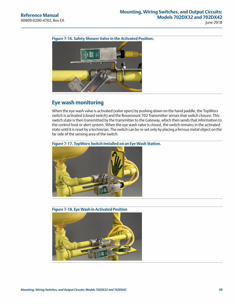
Reference Manual 00809-0200-4702, Rev EA
Mounting, Wiring Switches, and Output Circuits:Models 702DX32 and 702DX42
June 2018
Figure 7-16. Safety Shower Valve in the Activated Position.
Eye wash monitoring When the eye wash valve is activated (valve open) by pushing down on the hand paddle, the TopWorx switch is activated (closed switch) and the Rosemount 702 Transmitter senses that switch closure. This switch state is then transmitted by the transmitter to the Gateway, which then sends that information to the control host or alert system. When the eye wash valve is closed, the switch remains in the activated state until it is reset by a technician. The switch can be re-set only by placing a ferrous metal object on the far side of the sensing area of the switch.
Figure 7-17. TopWorx Switch Installed on an Eye Wash Station.
Figure 7-18. Eye Wash in Activated Position
69Mounting, Wiring Switches, and Output Circuits: Models 702DX32 and 702DX42

Reference Manual00809-0200-4702, Rev EA
Mounting, Wiring Switches, and Output Circuits: Models 702DX32 and 702DX42June 2018
Installation of safety shower and eye wash monitoring kitsDrawings to aid in the installation of safety shower and eye wash kits can be found in Appendix D: Safety Shower Monitoring on page 123 of this Reference Manual.
7.4 LCD displayif an LCD display is ordered, it will be shipped attached to the transmitter.
The optional LCD display can be rotated in 90-degree increments by squeezing the two tabs, pulling out, rotating and snapping back into place.
If the LCD display pins are inadvertently removed from the interface board, carefully re-insert the pins before snapping the LCD display back into place.
Installing the optional LCD displayTo install the LCD display, use Figure 7-19 on page 70 and the following instructions:
1. Remove the LCD display cover. Do not remove the instrument cover in explosive environments when the circuit is live.
2. Put the four-pin connector into the LCD display, rotate to the desired position and snap into place.
Note the following LCD display temperature limits:
Operating: –4 to 175 °F (–20 to 80 °C)Storage: –40 to 185 °F (–40 to 85 °C)
3. Replace the transmitter cover.
NoteOnly use Rosemount wireless LCD display part number: 00753-9004-0002.
Figure 7-19. Optional LCD Display
A. LCD display pinsB. LCD display displayC. LCD display cover
A
B C
70 Mounting, Wiring Switches, and Output Circuits: Models 702DX32 and 702DX42

Reference Manual 00809-0200-4702, Rev EA
Mounting, Wiring Switches, and Output Circuits:Models 702DX32 and 702DX42
June 2018
7.5 Grounding the transmitterThe Rosemount 702 Transmitter operates with the housing grounded or floating. Floating systems, however, can cause extra noise that may affect many types of readout devices. If the signal appears noisy or erratic, grounding at a single point may solve the problem. Grounding of the electronics enclosure should be done in accordance with local and national installation codes. Grounding is accomplished through the process connection using the internal or external case grounding terminal.
Determining grounding requirementsEach process installation has different grounding requirements. Use the options recommended by the facility for the specific switch type, or begin with Option 1, which is the most common.
Option 1
1. Connect switch wiring shield to the grounded transmitter housing.
2. Ensure that the transmitter housing is electrically isolated from the switch wiring.
Option 2
1. Ground switch wiring shield at the switch.
2. Ensure that the switch wiring and shield are electronically isolated from the transmitter housing.
NoteAlways use facility recommended wiring practices.
A
B
C
A
B
C
71Mounting, Wiring Switches, and Output Circuits: Models 702DX32 and 702DX42
Reference Manual00809-0200-4702, Rev EA
Mounting, Wiring Switches, and Output Circuits: Models 702DX32 and 702DX42June 2018
72 Mounting, Wiring Switches, and Output Circuits: Models 702DX32 and 702DX42

Reference Manual 00809-0200-4702, Rev EA
Commissioning: Models 702DX32 and 702DX42June 2018
Section 8 Commissioning: Models 702DX32 and 702DX42
Safety messages . . . . . . . . . . . . . . . . . . . . . . . . . . . . . . . . . . . . . . . . . . . . . . . . . . . . . . . . . . . . . . . . . . . . . . page 73Configuring wireless network communication . . . . . . . . . . . . . . . . . . . . . . . . . . . . . . . . . . . . . . . . . . . . page 74Field Communicator . . . . . . . . . . . . . . . . . . . . . . . . . . . . . . . . . . . . . . . . . . . . . . . . . . . . . . . . . . . . . . . . . . page 74Verifying operation . . . . . . . . . . . . . . . . . . . . . . . . . . . . . . . . . . . . . . . . . . . . . . . . . . . . . . . . . . . . . . . . . . . page 74
8.1 Safety messagesInstructions and procedures in this section may require special precautions to ensure the safety of the personnel performing the operations. Information that potentially raises safety issues is indicated by a warning symbol ( ). Refer to the following safety messages before performing an operation preceded by this symbol.
NoteThe Rosemount™ 702 Transmitter and all other wireless devices should be installed only after the gateway has been installed and is functioning properly.
Wireless devices should be powered up in order of proximity from the gateway, beginning with the device closest to the Gateway. This will result in a simpler and faster network installation.
Failure to follow these installation guidelines could result in death or serious injury.
Make sure only qualified personnel perform the installation.
Explosions could result in death or serious injury. Before connecting a Field Communicator in an explosive atmosphere, make sure the instruments are
installed in accordance with intrinsically safe or non-incendive field wiring practices.
Verify that the operating atmosphere of the transmitter is consistent with the appropriate hazardous locations certifications.
Process leaks could result in death or serious injury. Do not remove the switch while in operation.
Install and tighten sensors before applying pressure.
Electrical shock could cause death or serious injury.
Use extreme caution when making contact with the leads and terminals.
73Commissioning: Models 702DX32 and 702DX42
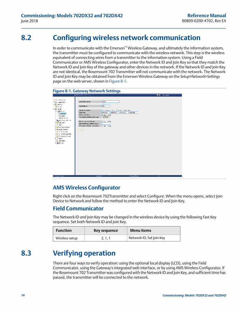
Reference Manual00809-0200-4702, Rev EA
Commissioning: Models 702DX32 and 702DX42June 2018
8.2 Configuring wireless network communicationIn order to communicate with the Emerson™ Wireless Gateway, and ultimately the information system, the transmitter must be configured to communicate with the wireless network. This step is the wireless equivalent of connecting wires from a transmitter to the information system. Using a Field Communicator or AMS Wireless Configurator, enter the Network ID and Join Key so that they match the Network ID and Join Key of the gateway and other devices in the network. If the Network ID and Join Key are not identical, the Rosemount 702 Transmitter will not communicate with the network. The Network ID and Join Key may be obtained from the Emerson Wireless Gateway on the Setup>Network>Settings page on the web server, shown in Figure 8-1.
Figure 8-1. Gateway Network Settings
AMS Wireless Configurator Right click on the Rosemount 702Transmitter and select Configure. When the menu opens, select Join Device to Network and follow the method to enter the Network ID and Join Key.
Field CommunicatorThe Network ID and Join Key may be changed in the wireless device by using the following Fast Key sequence. Set both Network ID and Join Key.
8.3 Verifying operationThere are four ways to verify operation: using the optional local display (LCD), using the Field Communicator, using the Gateway's integrated web interface, or by using AMS Wireless Configurator. If the Rosemount 702 Transmitter was configured with the Network ID and Join Key, and sufficient time has passed, the transmitter will be connected to the network.
Function Key sequence Menu items
Wireless setup 2, 1, 1 Network ID, Set Join Key
74 Commissioning: Models 702DX32 and 702DX42
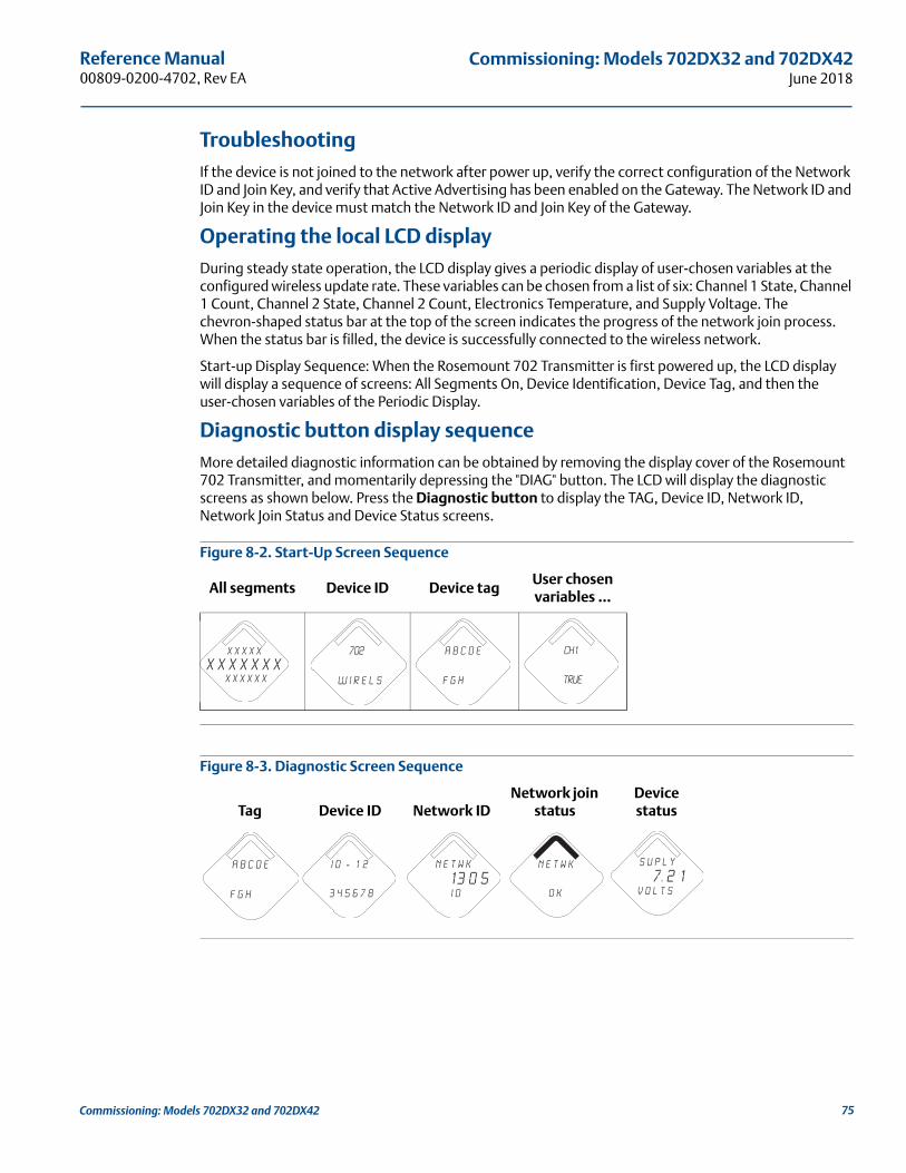
Reference Manual 00809-0200-4702, Rev EA
Commissioning: Models 702DX32 and 702DX42June 2018
TroubleshootingIf the device is not joined to the network after power up, verify the correct configuration of the Network ID and Join Key, and verify that Active Advertising has been enabled on the Gateway. The Network ID and Join Key in the device must match the Network ID and Join Key of the Gateway.
Operating the local LCD displayDuring steady state operation, the LCD display gives a periodic display of user-chosen variables at the configured wireless update rate. These variables can be chosen from a list of six: Channel 1 State, Channel 1 Count, Channel 2 State, Channel 2 Count, Electronics Temperature, and Supply Voltage. The chevron-shaped status bar at the top of the screen indicates the progress of the network join process. When the status bar is filled, the device is successfully connected to the wireless network.
Start-up Display Sequence: When the Rosemount 702 Transmitter is first powered up, the LCD display will display a sequence of screens: All Segments On, Device Identification, Device Tag, and then the user-chosen variables of the Periodic Display.
Diagnostic button display sequenceMore detailed diagnostic information can be obtained by removing the display cover of the Rosemount 702 Transmitter, and momentarily depressing the "DIAG" button. The LCD will display the diagnostic screens as shown below. Press the Diagnostic button to display the TAG, Device ID, Network ID, Network Join Status and Device Status screens.
Figure 8-2. Start-Up Screen Sequence
Figure 8-3. Diagnostic Screen Sequence
All segments Device ID Device tagUser chosen variables …
Tag Device ID Network IDNetwork join
statusDevice status
X X X X X
X X X X x x xx x x x x x
702
W I r e l s
A b c d e
f g h
CH1
True
A b c d e
f g h
i d - 1 2
3 4 5 6 7 8
n e t w k
13 0 5 I D
n e t w k
O K
S u p l y
7. 2 1v o l t s
75Commissioning: Models 702DX32 and 702DX42
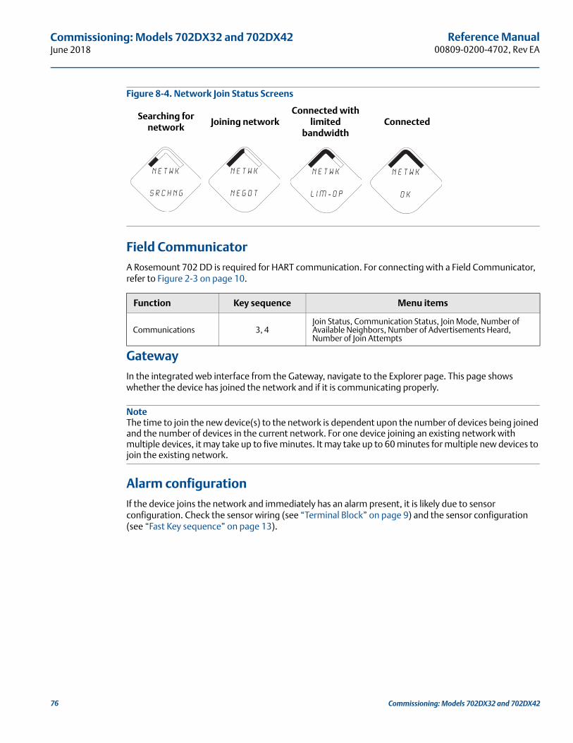
Reference Manual00809-0200-4702, Rev EA
Commissioning: Models 702DX32 and 702DX42June 2018
Figure 8-4. Network Join Status Screens
Field CommunicatorA Rosemount 702 DD is required for HART communication. For connecting with a Field Communicator, refer to Figure 2-3 on page 10.
GatewayIn the integrated web interface from the Gateway, navigate to the Explorer page. This page shows whether the device has joined the network and if it is communicating properly.
NoteThe time to join the new device(s) to the network is dependent upon the number of devices being joined and the number of devices in the current network. For one device joining an existing network with multiple devices, it may take up to five minutes. It may take up to 60 minutes for multiple new devices to join the existing network.
Alarm configurationIf the device joins the network and immediately has an alarm present, it is likely due to sensor configuration. Check the sensor wiring (see “Terminal Block” on page 9) and the sensor configuration (see “Fast Key sequence” on page 13).
Searching for network
Joining networkConnected with
limited bandwidth
Connected
Function Key sequence Menu items
Communications 3, 4Join Status, Communication Status, Join Mode, Number of Available Neighbors, Number of Advertisements Heard, Number of Join Attempts
N E T w K
S R C H N G
n e t w k
N E G O T
n e t w k
L I M - O P
n e t w k
O K
76 Commissioning: Models 702DX32 and 702DX42
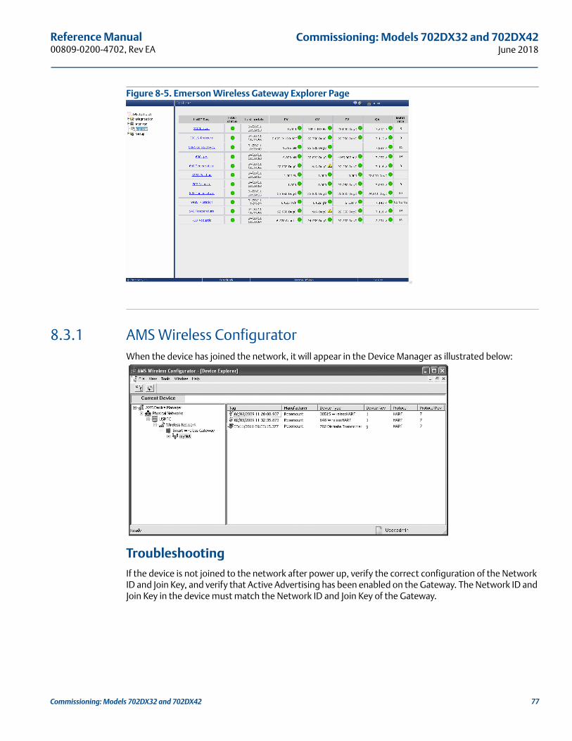
Reference Manual 00809-0200-4702, Rev EA
Commissioning: Models 702DX32 and 702DX42June 2018
Figure 8-5. Emerson Wireless Gateway Explorer Page
8.3.1 AMS Wireless ConfiguratorWhen the device has joined the network, it will appear in the Device Manager as illustrated below:
TroubleshootingIf the device is not joined to the network after power up, verify the correct configuration of the Network ID and Join Key, and verify that Active Advertising has been enabled on the Gateway. The Network ID and Join Key in the device must match the Network ID and Join Key of the Gateway.
77Commissioning: Models 702DX32 and 702DX42

Reference Manual00809-0200-4702, Rev EA
Commissioning: Models 702DX32 and 702DX42June 2018
Changing the network ID and join keyThe Network ID and Join Key may be obtained from the Gateway on the Setup>Network>Settings page on the web interface (see Figure 8-5 on page 77). The Network ID and Join Key may be changed in the wireless device by using the following Fast Key sequence.
Function Key Sequence Menu Items
Wireless 2,1,1 Join Device to Network
78 Commissioning: Models 702DX32 and 702DX42
Reference Manual 00809-0200-4702, Rev EA
Operation and Maintenance:Models 702DX32 and 702DX42
June 2018
Section 9 Operation and Maintenance: Models 702DX32 and 702DX42
Safety messages . . . . . . . . . . . . . . . . . . . . . . . . . . . . . . . . . . . . . . . . . . . . . . . . . . . . . . . . . . . . . . . . . . . . . .page 79Discrete input from switches . . . . . . . . . . . . . . . . . . . . . . . . . . . . . . . . . . . . . . . . . . . . . . . . . . . . . . . . . . .page 80Discrete output circuits . . . . . . . . . . . . . . . . . . . . . . . . . . . . . . . . . . . . . . . . . . . . . . . . . . . . . . . . . . . . . . . .page 86Interpreting the LCD display screen messages . . . . . . . . . . . . . . . . . . . . . . . . . . . . . . . . . . . . . . . . . . . .page 90Replacing the power module . . . . . . . . . . . . . . . . . . . . . . . . . . . . . . . . . . . . . . . . . . . . . . . . . . . . . . . . . . .page 97
9.1 Safety messagesInstructions and procedures in this section may require special precautions to ensure the safety of the personnel performing the operations. Information that potentially raises safety issues is indicated by a warning symbol ( ). Refer to the following safety messages before performing an operation preceded by this symbol.
Failure to follow these installation guidelines could result in death or serious injury.
Make sure only qualified personnel perform the installation.
Explosions could result in death or serious injury. Before connecting a Field Communicator in an explosive atmosphere, make sure the instruments are
installed in accordance with intrinsically safe or non-incendive field wiring practices.
Verify that the operating atmosphere of the transmitter is consistent with the appropriate hazardous locations certifications.
Process leaks could result in death or serious injury. Do not remove the switch while in operation.
Install and tighten sensors before applying pressure.
Electrical shock could cause death or serious injury.
Use extreme caution when making contact with the leads and terminals.
79Operation and Maintenance: Models 702DX32 and 702DX42

Reference Manual00809-0200-4702, Rev EA
Operation and Maintenance: Models 702DX32 and 702DX42June 2018
9.2 Discrete input from switches
9.2.1 Dry contact inputs, measurement option code 32, 42 (702DX32, 702DX42) The Rosemount 702 Transmitter has a pair of screw terminals for each of two channels, and a pair of communication terminals. These terminals are labeled as follows:
Figure 9-1. Terminal Diagram
9.2.2 Wireless output specifications
Dual InputThe Rosemount 702 Transmitter will accept the input from one or two single pole single throw switches on inputs CH1 and CH2. The wireless output of the transmitter will be both a primary variable (PV) and a secondary variable (SV). The PV is determined by the CH1 input. The SV is determined by the CH2 input. A closed switch drives a TRUE output. An Open switch drives a FALSE output.
NoteAny dry contact input can be inverted by the device, so as give the opposite effect. This is useful, for instance, if a normally open switch is used to replace a normally closed switch.
CH1+: Channel 1 Positive
CMN: Common
CH2+: Channel 2 Positive
CMN: Common
COMM: Communication
80 Operation and Maintenance: Models 702DX32 and 702DX42
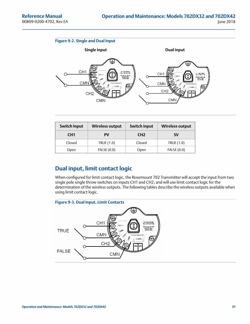
Reference Manual 00809-0200-4702, Rev EA
Operation and Maintenance: Models 702DX32 and 702DX42June 2018
Figure 9-2. Single and Dual Input
Dual input, limit contact logicWhen configured for limit contact logic, the Rosemount 702 Transmitter will accept the input from two single pole single throw switches on inputs CH1 and CH2, and will use limit contact logic for the determination of the wireless outputs. The following tables describe the wireless outputs available when using limit contact logic.
Figure 9-3. Dual Input, Limit Contacts
Single input Dual input
Switch Input Wireless output Switch input Wireless output
CH1 PV CH2 SV
Closed TRUE (1.0) Closed TRUE (1.0)
Open FALSE (0.0) Open FALSE (0.0)
81Operation and Maintenance: Models 702DX32 and 702DX42

Reference Manual00809-0200-4702, Rev EA
Operation and Maintenance: Models 702DX32 and 702DX42June 2018
Dual Input, opposing contact logicWhen configured for Opposing Contact Logic, the 702 Transmitter will accept the input from a single pole double throw switch on inputs CH1 and CH2, and will use opposing contact logic for the determination of the wireless outputs. The following tables describe the wireless outputs available when using opposing contact logic.
Figure 9-4. Dual Input, Opposing Contact
9.2.3 Momentary discrete inputs, measurement option code 32 and 42 (702DX32, 702DX42)The Rosemount 702 Transmitter is capable of measuring momentary discrete inputs of 10 millisecond or more in duration, regardless of the wireless update rate. At each wireless update, the device reports current discrete input state and an accumulating count of close-open cycles for each input channel.
Switch inputs Wireless outputs
CH1 CH2 PV SV
Open Open TRAVEL (0.5) TRAVEL (0.5)
Open Closed FALSE (0.0) FALSE (0.0)
Closed Open TRUE (1.0) TRUE (1.0)
Closed Closed FAULT(NaN) FAULT(NaN)
Switch inputs Wireless outputs
CH1 CH2 PV SV
Open Open FAULT(NaN) FAULT(NaN)
Open Closed FALSE (0.0) FALSE (0.0)
Closed Open TRUE (1.0) TRUE (1.0)
Closed Closed FAULT(NaN) FAULT(NaN)
82 Operation and Maintenance: Models 702DX32 and 702DX42

Reference Manual 00809-0200-4702, Rev EA
Operation and Maintenance: Models 702DX32 and 702DX42June 2018
Figure 9-5. Momentary Inputs and Accumulating Count
Figure 9-6. Reporting of Current Discrete State and Count in AMS Wireless Configurator
Setting variable reporting in AMS Wireless ConfiguratorThe Rosemount 702 Transmitter has two choices for variable reporting: Classic - Discrete State Only, or Enhanced – Discrete State and Count. In the Classic variable reporting mode, the transmitter will report variables exactly like the previous version of the device (measurement option code 22). In the Enhanced variable reporting mode, the transmitter will provide both current state of the discrete channels, and a count of the discrete state change cycles. Following is a table that shows the variable mapping for both cases. Variable Reporting can be set in AMS Wireless Configurator by going to Configure > Manual Setup > HART.
Table 9-1. Variable Mapping
Variable reporting PV SV TV QV
Classic – discrete state only CH1 State CH2 StateElectronics
temperatureSupply voltage
Enhanced – discrete state with count CH1 State CH2 State CH1 Count CH2 Count
83Operation and Maintenance: Models 702DX32 and 702DX42

Reference Manual00809-0200-4702, Rev EA
Operation and Maintenance: Models 702DX32 and 702DX42June 2018
Setting the reported value in AMS Wireless ConfiguratorThe Rosemount 702 Transmitter reports the discrete state of switches wired to the input channels. There are various pairs of discrete states that correspond to an open or closed input switch. This pair of discrete states is called the Reported Value and can be set in AMS Wireless Configurator by going to Configure > Manual Setup > Discrete Channels > Setup Channel X (1 or 2). Under Reported Value there is a drop down menu of choices. The Reported Value can be set independently for each of the two channels.
Figure 9-7. Setting the Reported Value
Reported Value: Table 9-2 gives the reported value choices and the names for each possible state. Also given are the corresponding analog value and discrete value for each possible state.
Value Name: The Name of the reported value will be seen in AMS Wireless Configurator, and on the device display. The device display may shorten the name to fit the available display segments.
Analog Value: The analog value is seen on the gateway web interface under the PV or SV. This is also the value that is reported through the gateway to a control host that requires an analog floating point value for PV or SV.
Discrete Value: The discrete value is reported through the gateway to a control host that requires the true discrete state value, rather than the floating point decimal of the Analog Value.
84 Operation and Maintenance: Models 702DX32 and 702DX42

Reference Manual 00809-0200-4702, Rev EA
Operation and Maintenance: Models 702DX32 and 702DX42June 2018
Table 9-2. State Table for Reported Values
NoteChanging logic option from direct to inverted has the effect of changing “Open Switch” to “Closed Switch” on the table above.
Variable reporting, limit contact or opposing contact logicIf the Rosemount 702 Transmitter has two inputs and is set for limit contact or opposing contact logic, there is a different list of reported values. Table 9-3 describes the values that are reported as a function of the Reported Value setting, and the four possible discrete states of True, False, Fault and Travel. Reference Figure 9-3 on page 81 for limit contact switches and Figure 9-4 on page 82 for opposing contact switches.
Table 9-3. Limit Contact and Opposing Contact
Dual independent, or single channel application types
Reported value
Value name Analog Value Discrete Value
Open switch
Closed switch
Open switch
Closed switch
Open switch
Closed switch
Default False True 0.000 1.000 240 242
Off/On Off On 0.000 1.000 0 1
Opened/Closed Opened Closed 46.000 6.000 46 6
Running/Stopped Stopped Running 25.000 26.000 25 26
Slow/Fast Slow Fast 8.000 7.000 8 7
Forward/Reverse Forward Reverse 9.000 10.000 9 10
Bottom/Top Bottom Top 12.000 11.000 12 11
Empty/Full Empty Full 14.000 13.000 14 13
Cold/Hot Cold Hot 16.000 15.000 16 15
Dry/Wet Dry Wet 32.000 33.000 32 33
Absent/Present Absent Present 45.000 44.000 45 44
Dual input limit contact logic, or dual input opposing contact logic application types
Value name Analog value Discrete value
Reported value
False switch active
True switch active
Fault TravelFalse
switch active
True switch active
Fault TravelFalse
switch active
True switch active
Fault Travel
Default False True Fault Travel 0.000 1.000 NAN 0.500 240 242 243 241
All Others False True Fault Travel 0.000 1.000 243.0 241.0 240 242 243 241
85Operation and Maintenance: Models 702DX32 and 702DX42

Reference Manual00809-0200-4702, Rev EA
Operation and Maintenance: Models 702DX32 and 702DX42June 2018
9.3 Discrete output circuitsOutput circuits, measurement option code 42The Rosemount 702 Transmitter has two channels that can each be configured for discrete input or output. Inputs must be dry contact switch inputs and these were described in a preceding section of this document. Outputs are a simple switch closure to activate an output circuit. Transmitter output does not provide any voltage or current, the output circuit must have power of its own. Transmitter output has maximum switch capacity per channel of 26 volts DC and 100 milliamps. A typical power supply for powering an output circuit can be 24 volts or lower.
NoteIt is very important that the polarity of the output circuit is as shown in the wiring diagrams, with the positive (+) side of the circuit wired to the CH2 + terminal, and the negative (–) side of the circuit wired to the CMN terminal. If the output circuit is wired backwards it will remain active (switch closed) regardless of the state of the output channel.
Discrete output switch functionalityThe discrete output of the Rosemount 702 Transmitter is driven by the host control system, through the Emerson Wireless Gateway, and out to the transmitter. The time required for this wireless communication from the gateway to the transmitter is dependent on many factors, including the size and topology of the network and the total amount of downstream traffic on the wireless network. For a network that is constructed to our best practices, typical delays in communication of a discrete output from the Gateway to the transmitter are 15 seconds or less. Remember that this delay is only part of the latency that will be observed in a control loop.
NoteThe output functionality of the Rosemount 702 Transmitter requires that the network is managed by a version 4 Emerson Wireless Gateway, with v4.3 firmware installed.
Figure 9-8. Output Circuit Wiring
86 Operation and Maintenance: Models 702DX32 and 702DX42

Reference Manual 00809-0200-4702, Rev EA
Operation and Maintenance: Models 702DX32 and 702DX42June 2018
Figure 9-9. Possible Configurations for Both Channel 1 and Channel 2
Discrete output switch voltage and current limitsIt is important to note that the maximum output switching capacity is 26 volts DC and 100 milliamps. If a greater is to be switched an interposing relay circuit can be used. Figure 9-9 shows an example of a circuit to switch higher currents or voltages.
Special considerations for dual output circuits:If both channels are connected to output circuits, it is very important that the CMN terminal of each circuit be at the same voltage. Employing a common ground for both output circuits is one way to ensure that both circuits have CMN terminals at the same voltage.
Figure 9-10. Dual Output Circuits with a Common Ground
Connecting two output circuits with a single power supplyIf two output circuits are connected to a single Rosemount 702 Transmitter with a single power supply, both CH + and CMN terminals must be connected to each output circuit. The negative power supply wires must be at the same voltage and connected to both CMN terminals.
87Operation and Maintenance: Models 702DX32 and 702DX42
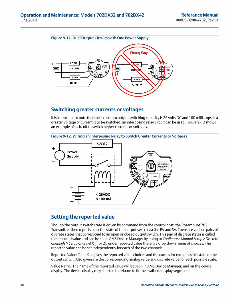
Reference Manual00809-0200-4702, Rev EA
Operation and Maintenance: Models 702DX32 and 702DX42June 2018
Figure 9-11. Dual Output Circuits with One Power Supply
Switching greater currents or voltagesIt is important to note that the maximum output switching capacity is 26 volts DC and 100 milliamps. If a greater voltage or current is to be switched, an interposing relay circuit can be used. Figure 9-12 shows an example of a circuit to switch higher currents or voltages.
Figure 9-12. Wiring an Interposing Relay to Switch Greater Currents or Voltages
Setting the reported valueThough the output switch state is driven by command from the control host, the Rosemount 702 Transmitter then reports back the state of the output switch via the PV and SV. There are various pairs of discrete states that correspond to an open or closed output switch. This pair of discrete states is called the reported value and can be set in AMS Device Manager by going to Configure > Manual Setup > Discrete Channels > Setup Channel X (1 or 2). under reported value there is a drop down menu of choices. The reported value can be set independently for each of the two channels.
Reported Value: Table 9-4 gives the reported value choices and the names for each possible state of the output switch. Also given are the corresponding analog value and discrete value for each possible state.
Value Name: The name of the reported value will be seen in AMS Device Manager, and on the device display. The device display may shorten the Name to fit the available display segments.
88 Operation and Maintenance: Models 702DX32 and 702DX42

Reference Manual 00809-0200-4702, Rev EA
Operation and Maintenance: Models 702DX32 and 702DX42June 2018
Analog Value: The analog value is seen on the gateway web interface under the PV or SV. This is also the value that is reported through the gateway to a control host that requires an analog floating point value for PV or SV.
Discrete Value: The discrete value is reported through the gateway to a control host that requires the true discrete state value, rather than the floating point decimal of the analog value.
Table 9-4. Discrete Output
NoteThe Fault condition applies to all reported value settings.
Changing logic option from direct to Inverted has the effect of changing “Open Switch” to “Closed Switch” on the table above.
The manual override of an output channel changes the value from the “Open Switch” state to the “Closed Switch” state.
Reported value
Value name Analog value Discrete value
Open switch
Closed switch
Open switch
Closed switch
Open switch
Closed switch
Default False True 0.000 1.000 240 242
Off/On Off On 0.000 1.000 0 1
Opened/Closed Opened Closed 46.000 6.000 46 6
Running/Stopped Stopped Running 25.000 26.000 25 26
Slow/Fast Slow Fast 8.000 7.000 8 7
Forward/Reverse Forward Reverse 9.000 10.000 9 10
Bottom/Top Bottom Top 12.000 11.000 12 11
Empty/Full Empty Full 14.000 13.000 14 13
Cold/Hot Cold Hot 16.000 15.000 16 15
Dry/Wet Dry Wet 32.000 33.000 32 33
Absent/Present Absent Present 45.000 44.000 45 44
Fault Fault 243.000 243
89Operation and Maintenance: Models 702DX32 and 702DX42

90
Reference Manual00809-0200-4702, Rev EA
Operation and Maintenance: Models 702DX32 and 702DX42June 2018
02DX42
Operation and Maintenance: Models 702DX32 and 79.4 Modbus and OPC mappingFollowing is a table of parameters that can be used for Modbus and OPC mapping. These parameters are used by the Emerson Wireless Gateway and can be found in the web interface of the gateway. some of these parameters are analog values and some are discrete, and this is noted in the description. The setpoint parameters are used to drive the output channel and for the readback of the state of the output channel.
9.5 Interpreting the LCD display screen messages
9.5.1 Startup screen sequenceThe following screens will display when the power module is first connected to the Rosemount 702 Transmitter.
Parameter Name Description Read/Write
CHANNEL_1_STATE Analog value for channel 1 state Read
CHANNEL_1_COUNTS Analog value for channel 1 state Read
CHANNEL_1_STATE_D Discrete value for channel 1 state Read
CHANNEL_1_SETPOINT_D Discrete value for channel 1 setpoint Read/Write
CHANNEL_2_STATE Analog value for channel 2 state Read
CHANNEL_2_COUNTS Analog value for channel 2 state Read
CHANNEL_2_STATE_D Discrete value for channel 2 state Read
CHANNEL_2_SETPOINT_D Discrete value for channel 2 setpoint Read/Write
SUPPLY_VOLTAGE Analog value for power module voltage Read
DEVICE_TEMPERATURE Analog value for device temperature Read
1. All Segments On: used to visually determine if there are any bad segments on the LCD display
2. Device Identification: used to determine Device Type.
X X X X X
X X X X x x xx x x x x x
702
W I r e l s
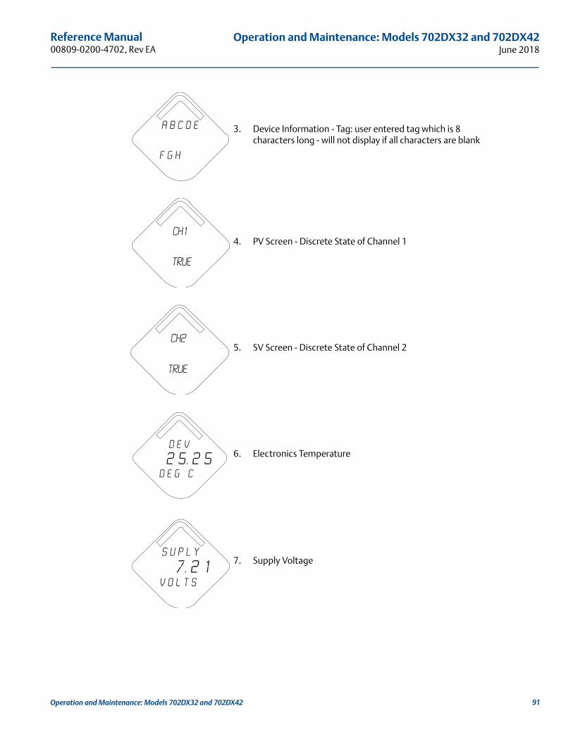
Reference Manual 00809-0200-4702, Rev EA
Operation and Maintenance: Models 702DX32 and 702DX42June 2018
3. Device Information - Tag: user entered tag which is 8 characters long - will not display if all characters are blank
4. PV Screen - Discrete State of Channel 1
5. SV Screen - Discrete State of Channel 2
6. Electronics Temperature
7. Supply Voltage
A b c d e
f g h
CH1
True
CH2
True
D E V
2 5. 2 5d e g c
S u p l y
7. 2 1v o l t s
91Operation and Maintenance: Models 702DX32 and 702DX42
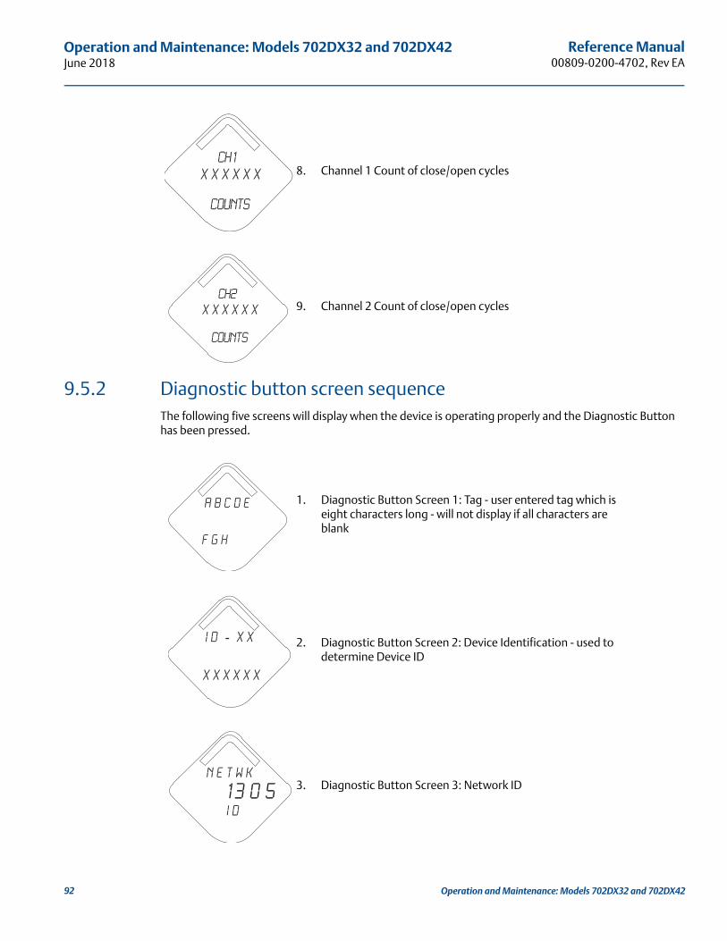
Reference Manual00809-0200-4702, Rev EA
Operation and Maintenance: Models 702DX32 and 702DX42June 2018
9.5.2 Diagnostic button screen sequenceThe following five screens will display when the device is operating properly and the Diagnostic Button has been pressed.
8. Channel 1 Count of close/open cycles
9. Channel 2 Count of close/open cycles
1. Diagnostic Button Screen 1: Tag - user entered tag which is eight characters long - will not display if all characters are blank
2. Diagnostic Button Screen 2: Device Identification - used to determine Device ID
3. Diagnostic Button Screen 3: Network ID
CH1
X X X X X X
Counts
CH2
X X X X X X
Counts
A b c d e
f g h
i d - X X
X X X X X X
n e t w k
13 0 5 I D
92 Operation and Maintenance: Models 702DX32 and 702DX42
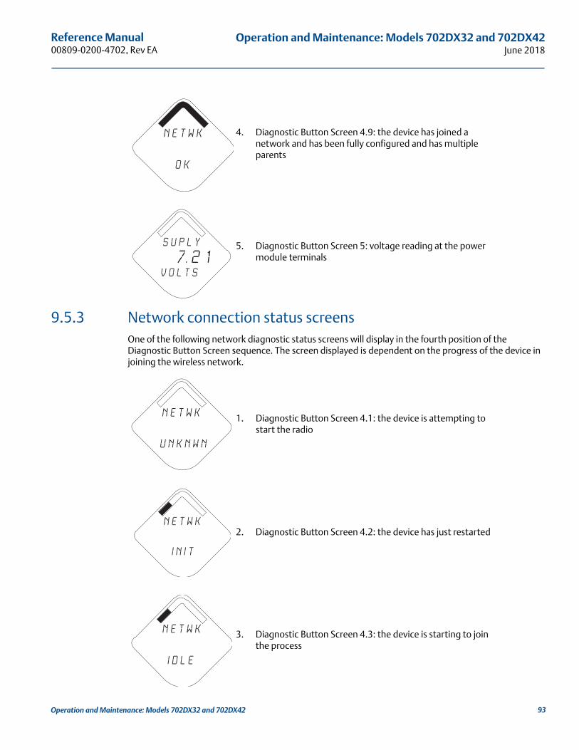
Reference Manual 00809-0200-4702, Rev EA
Operation and Maintenance: Models 702DX32 and 702DX42June 2018
9.5.3 Network connection status screensOne of the following network diagnostic status screens will display in the fourth position of the Diagnostic Button Screen sequence. The screen displayed is dependent on the progress of the device in joining the wireless network.
4. Diagnostic Button Screen 4.9: the device has joined a network and has been fully configured and has multiple parents
5. Diagnostic Button Screen 5: voltage reading at the power module terminals
1. Diagnostic Button Screen 4.1: the device is attempting to start the radio
2. Diagnostic Button Screen 4.2: the device has just restarted
3. Diagnostic Button Screen 4.3: the device is starting to join the process
n e t w k
O K
S u p l y
7. 2 1v o l t s
n e t w k
u n k n w n
n e t w k
I N I T
n e t w k
i d l e
93Operation and Maintenance: Models 702DX32 and 702DX42

94
Reference Manual00809-0200-4702, Rev EA
Operation and Maintenance: Models 702DX32 and 702DX42June 2018
4. Diagnostic Button Screen 4.4: the device is in a disconnected state and requires a “Force Join” command to join the network
5. Diagnostic Button Screen 4.5: the device is searching for the Network
6. Diagnostic Button Screen 4.6: the device is attempting to join a network
7. Diagnostic Button Screen 4.7: the device is connected to the Network, but is in a “Quarantined” state
8. Diagnostic Button Screen 4.8: the device is joined and operational, but is running with limited bandwidth for sending periodic data
n e t w k
D I S C N T
N E T w K
S R C H N G
n e t w k
N E G O T
n e t w k
c o n e c t
n e t w k
L I M - O P
Operation and Maintenance: Models 702DX32 and 702DX42
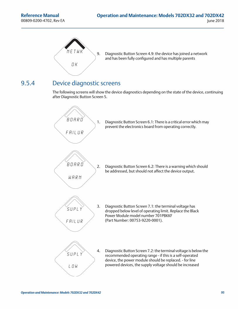
Reference Manual 00809-0200-4702, Rev EA
Operation and Maintenance: Models 702DX32 and 702DX42June 2018
9.5.4 Device diagnostic screensThe following screens will show the device diagnostics depending on the state of the device, continuing after Diagnostic Button Screen 5.
9. Diagnostic Button Screen 4.9: the device has joined a network and has been fully configured and has multiple parents
1. Diagnostic Button Screen 6.1: There is a critical error which may prevent the electronics board from operating correctly.
2. Diagnostic Button Screen 6.2: There is a warning which should be addressed, but should not affect the device output.
3. Diagnostic Button Screen 7.1: the terminal voltage has dropped below level of operating limit. Replace the Black Power Module model number 701PBKKF (Part Number: 00753-9220-0001).
4. Diagnostic Button Screen 7.2: the terminal voltage is below the recommended operating range - if this is a self-operated device, the power module should be replaced. - for line powered devices, the supply voltage should be increased
n e t w k
O K
B o a r d
f a i l u r
B o a r d
w A R N
s u p l y
f a i l u r
s u p l y
l o w
95Operation and Maintenance: Models 702DX32 and 702DX42

Reference Manual00809-0200-4702, Rev EA
Operation and Maintenance: Models 702DX32 and 702DX42June 2018
5. Diagnostic Button Screen 8: the device cannot retrieve information from the radio in the device - the device may still be operational and publishing HART data
6. Diagnostic Button Screen 9: configuration of the transmitter is invalid such that critical operation of the device may be affected - check the extended configuration status to identify which configuration item(s) need to be corrected
7. Diagnostic Button Screen 10: a switch attached to the transmitter has failed, and valid readings from that switch are no longer possible - check the switch and switch wiring connections - check additional status for more detailed information of the failure source
8. Diagnostic Button Screen 11: The device has not yet received all of the requested wireless bandwidth needed to operate as configured.
9. Diagnostic Button Screen 12: One or more output channels are being driven to a fault state.
r a d i o
f a i l u r
c o n f g
f a i l u r
s n s r
f a i l u r
b d W T h
l i m i t d
F a u l t
o u t p u t
96 Operation and Maintenance: Models 702DX32 and 702DX42
Reference Manual 00809-0200-4702, Rev EA
Operation and Maintenance: Models 702DX32 and 702DX42June 2018
Diagnostic Button Screens 13 +: All of the periodic screens except supply voltage will now be displayed to conclude the Diagnostic Button Screen Sequence. These screens are:Channel 1 StateChannel 2 StateElectronics TemperatureChannel 1 Count Channel 2 Count
NoteUse Rosemount Wireless LCD Part Number: 00753-9004-0002.
9.6 Replacing the power module Expected power module life is 10 years at reference conditions.(1)
When the power module needs to be replaced, remove the power module cover and the depleted power module. Replace the power module with a new Black Power Module, SmartPower™ Solutions model number 701PBKKF (part number 00753-9220-0001). Then replace the cover and tighten it specification. Always ensure a proper seal so that metal touches metal, but do not overtighten.
Handling the power module
The Black Power Module with the wireless unit contains two “C” size primary lithium/thionyl chloride batteries. Each battery contains approximately 2.5 grams of lithium, for a total of 5 grams in each pack. Under normal conditions, the battery materials are self-contained and are not reactive as long as the batteries and the battery pack integrity are maintained. Care should be taken to prevent thermal, electrical or mechanical damage. Contacts should be protected to prevent premature discharge.
Use caution when handling the power module. It may be damaged if dropped from heights in excess of 20 feet.
Battery hazards remain when cells are discharged.
Environmental considerations
As with any battery, local environmental rules and regulations should be consulted for proper management of spent batteries. If no specific requirements exist, recycling through a qualified recycler is encouraged. Consult the materials safety data sheet for battery specific information.
Shipping considerations
The unit was shipped to you without the power module installed. Remove the power module prior to shipping.
Each Black Power Module contains two “C” size primary lithium batteries. Primary lithium batteries are regulated in transportation by the U.S. Department of Transportation, and are also covered by International Air Transport Association (IATA), International Civil Aviation Organization (ICAO), and European Ground Transportation of Dangerous Goods (ARD). It is the responsibility of the shipper to ensure compliance with these or any other local requirements. Consult current regulations and requirements before shipping.
1. Reference conditions are 70 °F (21 °C), wireless update of once per minute, and routing data for three additional network devices.
97Operation and Maintenance: Models 702DX32 and 702DX42
Reference Manual00809-0200-4702, Rev EA
Operation and Maintenance: Models 702DX32 and 702DX42June 2018
9.7 Service supportTo expedite the return process outside of North America, contact your Emerson™ representative,
Within the United States, call the Emerson Response Center toll-free number 1 800 654 7768. The center, which is available 24 hours a day, will assist you with any needed information or materials.
The center will ask for product model and serial numbers, and will provide a Return Material Authorization (RMA) number. The center will also ask for the process material to which the product was last exposed.
Individuals who handle products exposed to a hazardous substance can avoid injury if they are informed of, and understand, the hazard. If the product being returned was exposed to a hazardous substance as defined by OSHA, a copy of the required Material Safety Data Sheet (MSDS) for each hazardous substance identified must be included with the returned goods.
98 Operation and Maintenance: Models 702DX32 and 702DX42

Reference DataJune 2018
Reference Manual00809-0100-4541, Rev EA
Appendix A Reference Data
Product Certifications . . . . . . . . . . . . . . . . . . . . . . . . . . . . . . . . . . . . . . . . . . . . . . . . . . . . . . . . . . . . . . . . . page 99Ordering Information, Specifications, and Drawings . . . . . . . . . . . . . . . . . . . . . . . . . . . . . . . . . . . . . . . page 99
A.1 Product CertificationsTo view current Rosemount 702 Product Certifications, follow these steps:
1. Go to Emerson.com/Rosemount/Rosemount-702.
2. Scroll as needed to the green menu bar and click Documents & Drawings.
3. Click Manuals & Guides.
4. Select the appropriate Quick Start Guide.
A.2 Ordering Information, Specifications, and Drawings
To view current Rosemount 702 Ordering Information, Specifications, and Drawings, follow these steps:
1. Go to Emerson.com/Rosemount/Rosemount-702.
2. Scroll as needed to the green menu bar and click Documents & Drawings.
3. For installation drawings, click Drawings & Schematics.
4. Select the appropriate document.
For ordering information, specifications, and dimensional drawings, click Data Sheets & Bulletins and select the appropriate Product Data Sheet.
Reference Data99

Reference DataJune 2018
Reference Manual 00809-0x00-xxxx, Rev XX
Reference Data 100
Reference Manual 00809-0200-4702, Rev EA
High Gain Remote Antenna OptionJune 2018
Appendix B High Gain Remote Antenna Option
Safety messages . . . . . . . . . . . . . . . . . . . . . . . . . . . . . . . . . . . . . . . . . . . . . . . . . . . . . . . . . . . . . . . . . . . . page 101Functional specifications . . . . . . . . . . . . . . . . . . . . . . . . . . . . . . . . . . . . . . . . . . . . . . . . . . . . . . . . . . . . page 102Installation considerations . . . . . . . . . . . . . . . . . . . . . . . . . . . . . . . . . . . . . . . . . . . . . . . . . . . . . . . . . . . page 103Transient/lightning considerations . . . . . . . . . . . . . . . . . . . . . . . . . . . . . . . . . . . . . . . . . . . . . . . . . . . . page 103Dimensional drawings . . . . . . . . . . . . . . . . . . . . . . . . . . . . . . . . . . . . . . . . . . . . . . . . . . . . . . . . . . . . . . . page 104Installing the high gain remote antenna . . . . . . . . . . . . . . . . . . . . . . . . . . . . . . . . . . . . . . . . . . . . . . . page 105
B.1 Safety messagesProcedures and instructions in this section may require special precautions to ensure the safety of the personnel performing the operations. Information that raises potential safety issues is indicated by a warning symbol ( ). Refer to the following safety messages before performing an operation preceded by this symbol.
When installing remote mount antennas for the wireless field device, always use established safety procedures to avoid falling or contact with high-power electrical lines.
Install remote antenna components for the wireless field device in compliance with local and national electrical codes and use best practices for lightning protection.
Before installing consult with the local area electrical inspector, electrical officer, and work area supervisor.
The wireless field device remote antenna option is specifically engineered to provide installation flexibility while optimizing wireless performance and local spectrum approvals. To maintain wireless performance and avoid non-compliance with spectrum regulations, do not change the length of cable or the antenna type.
If the supplied remote mount antenna kit is not installed per these instructions, Emerson is not responsible for wireless performance or non-compliance with spectrum regulations.
Be aware of overhead electrical power lines.
High Gain Remote Antenna Option 101

High Gain Remote Antenna OptionJune 2018
Reference Manual 00809-0200-4702, Rev EA
B.2 Functional specificationsOutput
WirelessHART® 2.4 GHz DSSS (direct sequence spread spectrum).
Radio frequency power output from antenna:
High gain remote (WN option) antenna: maximum of 40 mW (16 dBm) EIRP (equivalent isotropically radiated power)
Communications range2/3 mile (3,300 ft.) (1.0 km) with L.O.S.
Coaxial length25 ft. (7.6 m) with type N connections
Coaxial material Heavy duty, low loss LMR400 cable
Minimum coaxial bend diameter: 1.0 ft. (0.3 m)
Antenna Remote-mount omni directional antenna
Fiberglass and aluminum construction
8 Db Gain
Meets MIL-STD-810G (method 510.5, procedure I and II)
Physical specificationsWeight: 1.0 lb (0.4 kg)
RF lightning arrestor In-line lightning arrestor
Electrical connection: lightning arrestor MUST be grounded per local electrical codes and regulations.
Mounting bracket
Horizontal or vertical mast accommodation
Supported mast diameter: 1.0- to 2.5-in. (2.5 to 6.4 cm)
Aluminum bracket
Nickel/zinc plated mounting U-bolts
Ratings
NEMA® 4X, and IP66/67
Vibration3g max vibration
High Gain Remote Antenna Option 102
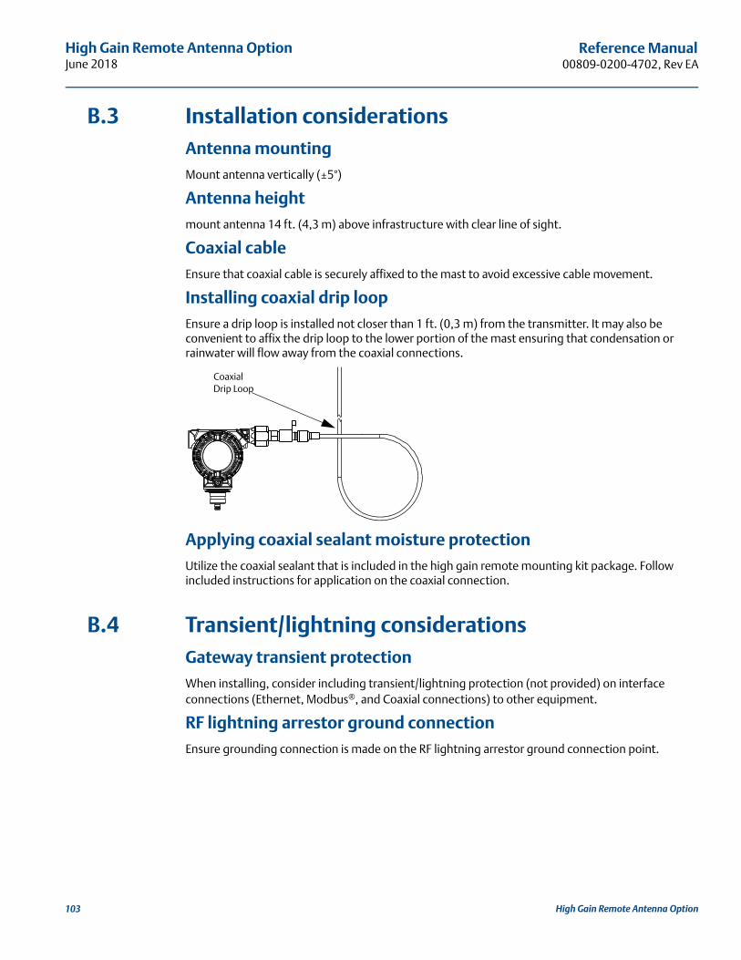
High Gain Remote Antenna OptionJune 2018
Reference Manual00809-0200-4702, Rev EA
on103
High Gain Remote Antenna OptiB.3 Installation considerationsAntenna mountingMount antenna vertically (±5°)
Antenna heightmount antenna 14 ft. (4,3 m) above infrastructure with clear line of sight.
Coaxial cableEnsure that coaxial cable is securely affixed to the mast to avoid excessive cable movement.
Installing coaxial drip loopEnsure a drip loop is installed not closer than 1 ft. (0,3 m) from the transmitter. It may also be convenient to affix the drip loop to the lower portion of the mast ensuring that condensation or rainwater will flow away from the coaxial connections.
Applying coaxial sealant moisture protectionUtilize the coaxial sealant that is included in the high gain remote mounting kit package. Follow included instructions for application on the coaxial connection.
B.4 Transient/lightning considerationsGateway transient protectionWhen installing, consider including transient/lightning protection (not provided) on interface connections (Ethernet, Modbus®, and Coaxial connections) to other equipment.
RF lightning arrestor ground connectionEnsure grounding connection is made on the RF lightning arrestor ground connection point.
Coaxial Drip Loop
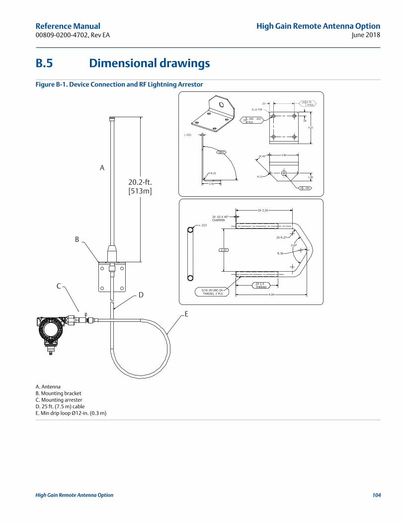
High Gain Remote Antenna OptionJune 2018
Reference Manual 00809-0200-4702, Rev EA
B.5 Dimensional drawings
Figure B-1. Device Connection and RF Lightning Arrestor
A. AntennaB. Mounting bracketC. Mounting arresterD. 25 ft. (7.5 m) cableE. Min drip loop Ø12-in. (0.3 m)
n `
n
n
.53 2.75 4 PLS
[X]
20.2-ft.[513m]
D
A
B
C
E
High Gain Remote Antenna Option 104

High Gain Remote Antenna OptionJune 2018
Reference Manual00809-0200-4702, Rev EA
B.6 Installing the high gain remote antenna 1. Mount the transmitter following best practice mounting procedures as outlined in the Quick Start
Guide and Manual.
2. Connect the RF lightning protector to the device and tighten.
3. Connect antenna to mounting bracket and tighten nut carefully.
RF lightning protector
High Gain Remote Antenna Option105

High Gain Remote Antenna OptionJune 2018
Reference Manual 00809-0200-4702, Rev EA
4. Unwind coaxial cable and connect the cable to both the antenna and the lightning protector connected to the transmitter, leaving one loop minimum for a drip loop. Ensure the drip loop is lower than the device, allowing water to flow away from the device.
5. Apply the coaxial sealant around each of the coaxial connections and at the lightning arrestor, making sure the RF connections are completely sealed.
High Gain Remote Antenna Option 106

High Gain Remote Antenna OptionJune 2018
Reference Manual00809-0200-4702, Rev EA
6. Attach U-bolts to mounting bracket in correct orientation ensuring that antenna will be positioned in a vertical position.
7. Tighten U-bolts to mast and ensure that antenna is pointed in a vertical direction.
High Gain Remote Antenna Option107

High Gain Remote Antenna OptionJune 2018
Reference Manual 00809-0200-4702, Rev EA
High Gain Remote Antenna Option 108

Reference Manual 00809-0200-4702, Rev EA
Safety Shower MonitoringJune 2018
Appendix C Safety Shower Monitoring
Installation instructions . . . . . . . . . . . . . . . . . . . . . . . . . . . . . . . . . . . . . . . . . . . . . . . . . . . . . . . . . . . . . page 109Installation drawings . . . . . . . . . . . . . . . . . . . . . . . . . . . . . . . . . . . . . . . . . . . . . . . . . . . . . . . . . . . . . . . . page 111
C.1 Installation instructionsUse these instructions to mount 10 Series GO™ Switches on a universal thermal shower and eyewash.
Refer to Figure C-1 on page 111, Figure C-2 on page 112, and the parts lists for mounting parts identifi-cation. Refer to the 10 Series instruction manual for 10 Series parts identification. Refer to the appropriate shower and eyewash instruction manual for shower and eyewash installation, operation, maintenance, and parts identification.
1. Isolate the control valve from the process line pressure, release pressure from both sides of the valve body, and drain the process media from both sides of the valve. Shut off all pressure lines to the shower and eyewash, releasing all pressure from the shower and eyewash. Use lock-out procedures to be sure that the above measures stay in effect while you work on the equipment.
2. Begin shower mounting kit installation by drilling two holes in the shower handle as shown.
3. Attach the target arm to the shower handle using two #10–24 x 0.75 hex head screws, two #10 lock washers, and two #10–24 hex nuts.
4. Loosely attach the target magnet to the target arm using two #10–24 x 0.75 flat head screws, two #10 lock washers, and two #10–24 Hex Nuts.
5. Fasten the two mounting brackets to the shower using the four 1/4–20 x 10.00 threaded studs, eight 1/4-in. plain washers, eight 1/4-in. lock washers, and sixteen 1/4–20 hex nuts.
6. Loosely attach the 10 Series GO Switch to the mounting plate with the hardware provided.
7. Fasten the mounting plate to the mounting brackets with four 1/4-20 x 0.75 hex head screws, four 1/4-in. plain washers, four 1/4-in. lock washers, and four 1/4–20 hex nuts.
8. Adjust the mounting plate, 10 Series GO Switch, and target magnet as needed so that the magnet properly engages the switch. Tighten hardware to hold the mounting plate, 10 Series GO Switch, and target magnet in place.
9. Begin Eyewash mounting installation by loosely attaching the two mounting brackets to the eyewash using the four 1/4–20 x 10.00 threaded studs, eight 1/4” plain washers, eight 1/4” lock washers, and sixteen 1/4–20 hex nuts.
Safety Shower Monitoring 109
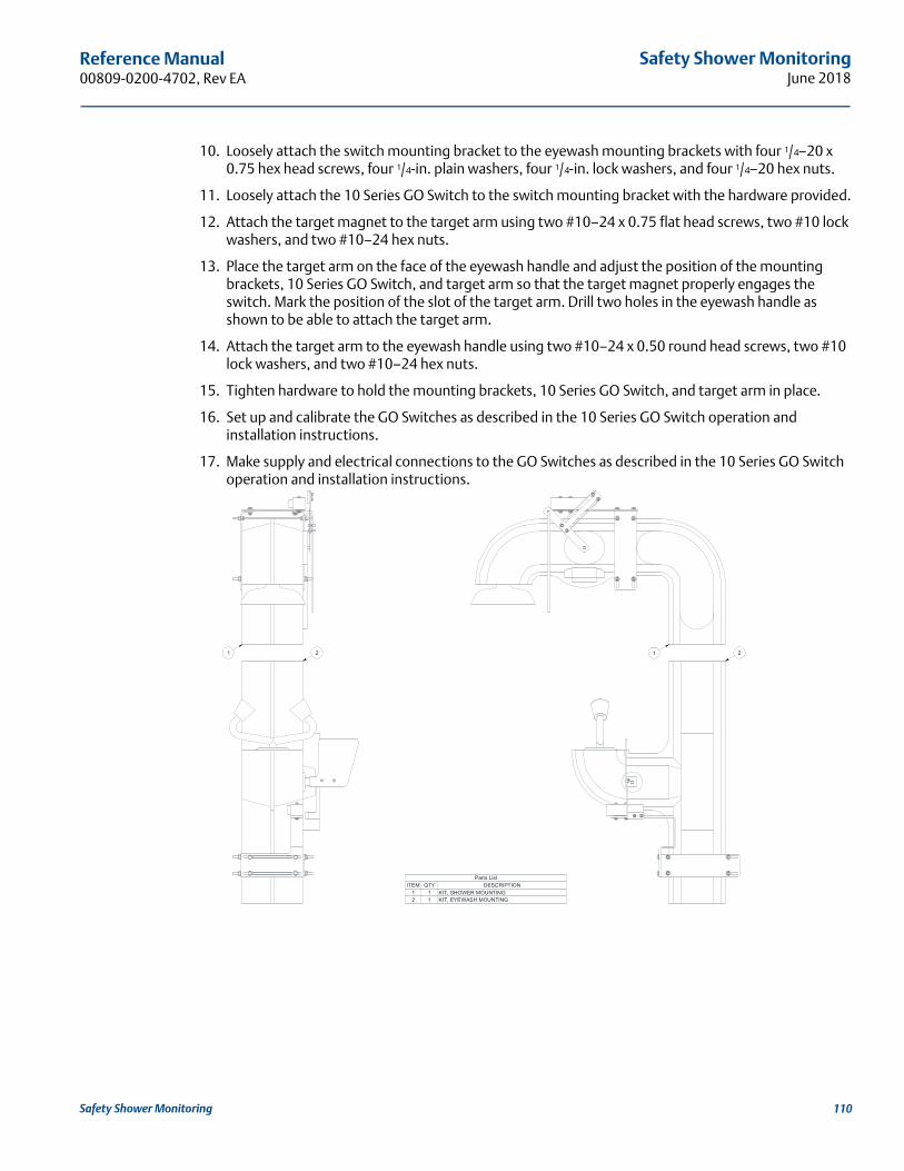
Safety Shower MonitoringJune 2018
Reference Manual 00809-0200-4702, Rev EA
10. Loosely attach the switch mounting bracket to the eyewash mounting brackets with four 1/4–20 x 0.75 hex head screws, four 1/4-in. plain washers, four 1/4-in. lock washers, and four 1/4–20 hex nuts.
11. Loosely attach the 10 Series GO Switch to the switch mounting bracket with the hardware provided.
12. Attach the target magnet to the target arm using two #10–24 x 0.75 flat head screws, two #10 lock washers, and two #10–24 hex nuts.
13. Place the target arm on the face of the eyewash handle and adjust the position of the mounting brackets, 10 Series GO Switch, and target arm so that the target magnet properly engages the switch. Mark the position of the slot of the target arm. Drill two holes in the eyewash handle as shown to be able to attach the target arm.
14. Attach the target arm to the eyewash handle using two #10–24 x 0.50 round head screws, two #10 lock washers, and two #10–24 hex nuts.
15. Tighten hardware to hold the mounting brackets, 10 Series GO Switch, and target arm in place.
16. Set up and calibrate the GO Switches as described in the 10 Series GO Switch operation and installation instructions.
17. Make supply and electrical connections to the GO Switches as described in the 10 Series GO Switch operation and installation instructions.
Parts ListDESCRIPTIONQTYITEM
KIT, SHOWER MOUNTING11KIT, EYEWASH MOUNTING12
21 1 2
Safety Shower Monitoring 110
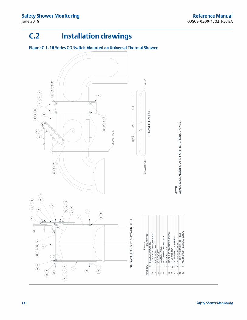
Safety Shower MonitoringJune 2018
Reference Manual00809-0200-4702, Rev EA
111
C.2 Installation drawings
Figure C-1. 10 Series GO Switch Mounted on Universal Thermal Shower
SH
OW
N W
ITH
OU
T SH
OW
ER P
ULL
Par
ts L
ist
DE
SCR
IPTI
ON
QTY
ITEM
BRA
CK
ET, M
OU
NTI
NG
21
1/4-
20 X
10.
00 S
TUD
, TH
RE
ADED
42
PLA
TE, M
OU
NTI
NG
13
ARM
, TA
RG
ET1
4M
AGN
ET,
TAR
GE
T1
5#1
0 W
ASH
ER
, SP
RIN
G L
OC
K4
6#1
0-24
NU
T, H
EX4
7#1
0-24
X .7
5 FL
AT
HEA
D S
CR
EW2
81/
4-20
NU
T, H
EX20
91/
4" W
ASH
ER
, LO
CK/
SPR
ING
1210
1/4"
WAS
HE
R, P
LAIN
1211
1/4-
20 X
.75
SCR
EW, H
EX H
EAD
412
#10-
24 X
0.7
5" H
EX H
EAD
SC
RE
W2
132
911
910 2
911
87
65
4
1
3
137
6
1
2
2
911
911
910
910
1112
910
1112
1211
109
3
29
1011
29
1011
4
87
6
1
5
137
6
(.25)
NO
TE:
GIV
EN D
IMEN
SIO
NS
ARE
FOR
REF
EREN
CE
ON
LY.
SH
OW
ER H
AND
LE
3.00
.875
Ø.2
29.2
17
VAL
VE S
HO
WER
PU
LL
SH
OW
ER
PU
LL
Safety Shower Monitoring

Safety Shower MonitoringJune 2018
Reference Manual 00809-0200-4702, Rev EA
Figure C-2. 10 Series GO Switch Mounted on Universal Thermal Eyewash
SHO
WN
WIT
HO
UT
MO
UN
TIN
G B
RA
CK
ET
Par
ts L
ist
DE
SCR
IPTI
ON
QTY
ITEM
BR
AC
KE
T, M
OU
NTI
NG
21
1/4-
20 X
10.
00 S
TUD
, TH
REA
DE
D4
21/
4-20
NU
T, H
EX20
31/
4" W
ASH
ER
, PLA
IN12
41/
4" W
AS
HE
R, L
OC
K/S
PRIN
G12
5B
RA
CK
ET,
MO
UN
TIN
G1
6#1
0-24
X .7
5 FL
AT
HEA
D S
CR
EW
27
#10-
24 N
UT,
HEX
48
#10
WA
SHER
, SPR
ING
LO
CK
49
MA
GN
ET, T
ARG
ET1
10A
RM
, TA
RG
ET1
11#1
0-24
X .5
0 SC
RE
W, R
OU
ND
HEA
D2
121/
4-20
X .7
5 SC
REW
, HE
X H
EAD
413
1
634
5
34
5
34
5
34
5
11
10
129
8
2 2
135
43
135
43
135
43
135
43
1
23
45
23
45
23
45
6
135
43
78
9
11
129
8
(.25)
EYE
WA
SH H
AND
LE
1.50
Ø.2
29.2
17
NO
TE:
GIV
EN D
IMEN
SIO
NS
AR
E F
OR
REF
EREN
CE
ON
LY.
Safety Shower Monitoring 112

Safety Shower MonitoringJune 2018
Reference Manual00809-0200-4702, Rev EA
Figure C-3. 10 Series GO Switch Universal Shower
SH
OW
ER H
AND
LE
1 1
2 2
3 3
4 4
AA
BB
CC
DD
Par
ts L
ist
DE
SC
RIP
TIO
NQ
TYIT
EM
MA
GN
ET,
TA
RG
ET
11
AR
M, T
AR
GE
T1
2#1
0-24
X .7
5 FL
AT
HE
AD
SC
RE
W2
3#1
0 W
AS
HE
R, S
PR
ING
LO
CK
4
4#1
0-24
NU
T, H
EX
4
5B
RA
CK
ET,
MO
UN
TIN
G1
6#1
0-24
X .5
0 S
CR
EW
, HE
X H
EA
D2
75/
16-1
8 X
1.0
0 1.
00" N
PT
U-B
OLT
28
5/16
WA
SH
ER
, PLA
IN4
9S
CA
LE:
SIZ
E:
SH
EE
T:
DW
G N
O.
RE
V
NO
TIC
E: D
raw
ing
cont
ains
con
fiden
tial &
pro
prie
tary
mat
eria
l and
is fu
rnis
hed
upon
cond
ition
that
it w
ill n
ot b
e us
ed in
any
way
det
rimen
tal t
o th
e in
tere
st o
f TO
PW
OR
X IN
C.
UN
LES
S O
THE
RW
ISE
SP
EC
IFIE
DTO
LER
AN
CE
S: .
XX
.0
1,.X
XX
.005
, AN
GLE
S
UN
IT O
F M
EA
SU
RE
INC
HE
SD
O N
OT
SCAL
E T
HIS
DR
AW
ING
AN
SI Y
14.5
/ISO
110
1
DR
AW
ND
ATE
MFG
APP
RO
VE
D
STA
TUS
:
OF
RE
VIS
ION
DA
TEB
YIG
B11
/12/
2010
BD
11/1
2/20
10
RK
C11
/12/
2010
Rel
ease
d10
SE
RIE
S G
O S
WIT
CH
KIT
, MO
UN
TIN
G
4-U
1306
0-S
512
C1
1N
ON
E
207
/06/
11R
DC
UN
IVE
RS
AL
SH
OW
ER
, 3/4
" - 2
" NP
T
2.00
.875
.219
2X
6
9 8
2
SHO
WE
R H
AN
DLE
54
3
75
4
1
2
54
3
675
4
8
9
1
2
54
3
6
75
4
8
99
NO
TE:
-DR
ILL
SHO
WER
HA
ND
LE A
S S
HO
WN
BE
FOR
E A
SS
EM
BLI
NG
KIT
.-K
IT P
RO
VID
ED
WIT
H M
OU
NTI
NG
HA
RD
WA
RE
FO
R 1
" NP
T P
IPE
ON
LY. U
-BO
LTS
FO
R O
THE
R P
IPE
SIZ
ES
MU
ST
BE
PR
OV
IDE
D B
Y U
SE
R.
-GIV
EN
DIM
EN
SIO
NS
AR
E F
OR
RE
FER
EN
CE
ON
LY.
(10.
14)
(7.4
1)
(4.0
0)
Safety Shower Monitoring113

Safety Shower MonitoringJune 2018
Reference Manual 00809-0200-4702, Rev EA
Figure C-4. Type 10 Series Switch with or without Latcher
VIE
W A
-A
1 1
2 2
3 3
4 4
AA
BB
CC
DD
SC
ALE
:S
IZE
:S
HE
ET:
DW
G N
O.
RE
V
NO
TIC
E: D
raw
ing
cont
ains
con
fiden
tial &
pro
prie
tary
mat
eria
l and
is fu
rnis
hed
upon
cond
ition
that
it w
ill n
ot b
e us
ed in
any
way
det
rimen
tal t
o th
e in
tere
st o
f TO
PW
OR
X IN
C.
UN
LES
S O
THE
RW
ISE
SP
EC
IFIE
DTO
LER
AN
CE
S: .
XX
.0
1,.X
XX
.005
, AN
GLE
S
UN
IT O
F M
EA
SU
RE
INC
HE
SD
O N
OT
SCAL
E T
HIS
DR
AW
ING
AN
SI Y
14.5
/ISO
110
1
DR
AW
ND
ATE
MFG
APP
RO
VE
D
STA
TUS
:
OF
RE
VIS
ION
DA
TEB
YC
MM
11/1
5/20
10
BD
11/1
5/20
10
RK
C11
/15/
2010
Rel
ease
dTy
pe 1
0 S
erie
s S
witc
h w
ith o
r
KIT
, MO
UN
TIN
G
4-U
1306
1-S
512
C1
1N
ON
E
207
/06/
11R
DC
With
out L
atch
er
A A
Par
ts L
ist
DE
SC
RIP
TIO
NQ
TYIT
EM
VA
LVE
, BA
LL .5
NP
T1
1#1
0 W
ASH
ER
, SP
RIN
G L
OC
K
42
#10-
24 N
UT,
HE
X
23
MA
GN
ET,
TA
RG
ET
14
#10-
24 X
.75
FLA
T H
EA
D S
CR
EW
25
BR
AC
KE
T, M
OU
NTI
NG
16
#10-
24 X
.375
SC
RE
W, H
EX
HE
AD2
7H
AN
DLE
/LA
BE
L A
SS
Y1
8
8
1
6
10 S
ER
IES
SW
ITC
H
8
4
72
53
2
72
4(6
.88)
(7.6
7)
(6.7
5)N
OTE
:-G
IVE
N D
IME
NS
ION
S A
RE
FO
R R
EFE
RE
NC
E O
NLY
.
Safety Shower Monitoring 114


Reference Manual00809-0200-4702, Rev EA
June 2018
Global HeadquartersEmerson Automation Solutions 6021 Innovation Blvd.Shakopee, MN 55379, USA
+1 800 999 9307 or +1 952 906 8888+1 952 949 7001 [email protected]
North America Regional OfficeEmerson Automation Solutions8200 Market Blvd.Chanhassen, MN 55317, USA
+1 800 999 9307 or +1 952 906 8888+1 952 949 7001 [email protected]
Latin America Regional OfficeEmerson Automation Solutions1300 Concord Terrace, Suite 400Sunrise, FL 33323, USA
+1 954 846 5030+1 954 846 [email protected]
Europe Regional OfficeEmerson Automation Solutions Europe GmbHNeuhofstrasse 19a P.O. Box 1046CH 6340 BaarSwitzerland
+41 (0) 41 768 6111+41 (0) 41 768 6300 [email protected]
Asia Pacific Regional OfficeEmerson Automation Solutions 1 Pandan CrescentSingapore 128461
+65 6777 8211+65 6777 0947 [email protected]
Middle East and Africa Regional OfficeEmerson Automation SolutionsEmerson FZE P.O. Box 17033Jebel Ali Free Zone - South 2Dubai, United Arab Emirates
+971 4 8118100+971 4 8865465 [email protected]
Linkedin.com/company/Emerson-Automation-Solutions
Twitter.com/Rosemount_News
Facebook.com/Rosemount
Youtube.com/user/RosemountMeasurement
Google.com/+RosemountMeasurement
Standard Terms and Conditions of Sale can be found on the Terms and Conditions of Sale page.The Emerson logo is a trademark and service mark of Emerson Electric Co. Rosemount is a mark of one of the Emerson family of companies.All other marks are the property of their respective owners.© 2018 Emerson. All rights reserved.