Embed Size (px)
Citation preview
Reference Manual00809-0100-4030, Rev ED
April 2015
Rosemount 2120Full-featured Vibrating Fork Liquid Level Switch

Reference Manual00809-0100-4030, Rev ED
Title PageApril 2015
Rosemount 2120Full-featured Vibrating ForkLiquid Level Switch
Read this manual before working with the product. For personal and system safety, and for optimum product performance, make sure you thoroughly understand the contents before installing, using, or maintaining this product.
For technical assistance, contacts are listed below:
Customer Central
Technical support, quoting, and order-related questions.
United States - 1-800-999-9307 (7:00 am to 7:00 pm CST)
Asia Pacific- 65 777 8211
Europe/ Middle East/ Africa - 49 (8153) 9390
North American Response Center
Equipment service needs.
1-800-654-7768 (24 hours—includes Canada)
Outside of these areas, contact your local Emerson Process Management representative.
The products described in this document are NOT designed for nuclear-qualified applications. Using non-nuclear qualified products in applications that require nuclear-qualified hardware or products may cause inaccurate readings.
For information on Rosemount nuclear-qualified products, contact your local Emerson Process Management Sales Representative.

Reference Manual00809-0100-4030, Rev ED
ContentsApril 2015
Contents
1Section 1: Introduction1.1 Safety messages. . . . . . . . . . . . . . . . . . . . . . . . . . . . . . . . . . . . . . . . . . . . . . . . . . . . . . . . 1
1.2 Manual overview . . . . . . . . . . . . . . . . . . . . . . . . . . . . . . . . . . . . . . . . . . . . . . . . . . . . . . . 2
1.3 Models covered . . . . . . . . . . . . . . . . . . . . . . . . . . . . . . . . . . . . . . . . . . . . . . . . . . . . . . . . 2
1.4 Introduction to the Rosemount 2120 . . . . . . . . . . . . . . . . . . . . . . . . . . . . . . . . . . . . . 2
1.4.1 Features list. . . . . . . . . . . . . . . . . . . . . . . . . . . . . . . . . . . . . . . . . . . . . . . . . . . . . 2
1.4.2 Measurement principle . . . . . . . . . . . . . . . . . . . . . . . . . . . . . . . . . . . . . . . . . . 3
1.4.3 Short fork technology. . . . . . . . . . . . . . . . . . . . . . . . . . . . . . . . . . . . . . . . . . . . 3
1.4.4 Special features . . . . . . . . . . . . . . . . . . . . . . . . . . . . . . . . . . . . . . . . . . . . . . . . . 4
1.5 Service support . . . . . . . . . . . . . . . . . . . . . . . . . . . . . . . . . . . . . . . . . . . . . . . . . . . . . . . . 6
1.6 Product recycling and disposal . . . . . . . . . . . . . . . . . . . . . . . . . . . . . . . . . . . . . . . . . . . 6
2Section 2: Installation2.1 Safety messages. . . . . . . . . . . . . . . . . . . . . . . . . . . . . . . . . . . . . . . . . . . . . . . . . . . . . . . . 7
2.2 Considerations before installation . . . . . . . . . . . . . . . . . . . . . . . . . . . . . . . . . . . . . . . . 8
2.2.1 Safety considerations . . . . . . . . . . . . . . . . . . . . . . . . . . . . . . . . . . . . . . . . . . . . 8
2.2.2 Environmental considerations . . . . . . . . . . . . . . . . . . . . . . . . . . . . . . . . . . . . 8
2.2.3 Application considerations . . . . . . . . . . . . . . . . . . . . . . . . . . . . . . . . . . . . . . . 9
2.2.4 Installation considerations. . . . . . . . . . . . . . . . . . . . . . . . . . . . . . . . . . . . . . . 11
2.2.5 Installation recommendations . . . . . . . . . . . . . . . . . . . . . . . . . . . . . . . . . . . 12
2.2.6 Installation examples . . . . . . . . . . . . . . . . . . . . . . . . . . . . . . . . . . . . . . . . . . . 15
2.3 Installation procedures . . . . . . . . . . . . . . . . . . . . . . . . . . . . . . . . . . . . . . . . . . . . . . . . .16
2.3.1 Mechanical . . . . . . . . . . . . . . . . . . . . . . . . . . . . . . . . . . . . . . . . . . . . . . . . . . . . 16
2.3.2 Correct fork alignment . . . . . . . . . . . . . . . . . . . . . . . . . . . . . . . . . . . . . . . . . . 17
2.3.3 Tightening the threaded Rosemount 2120 . . . . . . . . . . . . . . . . . . . . . . . . 19
2.3.4 Insulation . . . . . . . . . . . . . . . . . . . . . . . . . . . . . . . . . . . . . . . . . . . . . . . . . . . . . 19
2.4 Setting the mode switch and switching time delay. . . . . . . . . . . . . . . . . . . . . . . . .20
2.5 LED indication. . . . . . . . . . . . . . . . . . . . . . . . . . . . . . . . . . . . . . . . . . . . . . . . . . . . . . . . .21
2.6 Electrical installation . . . . . . . . . . . . . . . . . . . . . . . . . . . . . . . . . . . . . . . . . . . . . . . . . . .22
2.6.1 Direct load switching electronics cassette . . . . . . . . . . . . . . . . . . . . . . . . . 22
2.6.2 PNP/PLC electronics cassette . . . . . . . . . . . . . . . . . . . . . . . . . . . . . . . . . . . . 24
2.6.3 Relay output electronics cassette (standard version) . . . . . . . . . . . . . . . . 25
2.6.4 Relay output electronics cassette (12 Vdc nominal version). . . . . . . . . . 26
2.6.5 NAMUR electronics cassette . . . . . . . . . . . . . . . . . . . . . . . . . . . . . . . . . . . . . 27
2.6.6 8/16 mA electronics cassette . . . . . . . . . . . . . . . . . . . . . . . . . . . . . . . . . . . . 28
vContents
Reference Manual00809-0100-4030, Rev ED
ContentsApril 2015
vi Contents
3Section 3: Service and Troubleshooting3.1 Safety messages. . . . . . . . . . . . . . . . . . . . . . . . . . . . . . . . . . . . . . . . . . . . . . . . . . . . . . .29
3.2 Magnetic test point . . . . . . . . . . . . . . . . . . . . . . . . . . . . . . . . . . . . . . . . . . . . . . . . . . . .30
3.3 Inspection . . . . . . . . . . . . . . . . . . . . . . . . . . . . . . . . . . . . . . . . . . . . . . . . . . . . . . . . . . . .31
3.4 Maintenance. . . . . . . . . . . . . . . . . . . . . . . . . . . . . . . . . . . . . . . . . . . . . . . . . . . . . . . . . .31
3.5 Spare parts . . . . . . . . . . . . . . . . . . . . . . . . . . . . . . . . . . . . . . . . . . . . . . . . . . . . . . . . . . .32
3.6 Troubleshooting . . . . . . . . . . . . . . . . . . . . . . . . . . . . . . . . . . . . . . . . . . . . . . . . . . . . . .32
3.7 Replacement and calibration of electronic cassettes . . . . . . . . . . . . . . . . . . . . . . .33
3.7.1 Replacement sequence . . . . . . . . . . . . . . . . . . . . . . . . . . . . . . . . . . . . . . . . . 33
3.7.2 Calibration sequence . . . . . . . . . . . . . . . . . . . . . . . . . . . . . . . . . . . . . . . . . . . 35
4Appendix A: Reference DataA.1 Specifications . . . . . . . . . . . . . . . . . . . . . . . . . . . . . . . . . . . . . . . . . . . . . . . . . . . . . . . . .37
A.2 Dimensional drawings . . . . . . . . . . . . . . . . . . . . . . . . . . . . . . . . . . . . . . . . . . . . . . . . .42
A.2.1 3/4 and 1-in. threaded mounting (standard length) . . . . . . . . . . . . . . . . . 42
A.2.2 3/4 and 1-in. thread mounting (extended length) . . . . . . . . . . . . . . . . . . . 43
A.2.3 2-in. thread mounting . . . . . . . . . . . . . . . . . . . . . . . . . . . . . . . . . . . . . . . . . . 44
A.2.4 Flange mounting (standard length) . . . . . . . . . . . . . . . . . . . . . . . . . . . . . . . 45
A.2.5 Flange mounting (extended length) . . . . . . . . . . . . . . . . . . . . . . . . . . . . . . 46
A.2.6 Mobrey ‘A’ and ‘G’ flanges. . . . . . . . . . . . . . . . . . . . . . . . . . . . . . . . . . . . . . . 47
A.3 Ordering information . . . . . . . . . . . . . . . . . . . . . . . . . . . . . . . . . . . . . . . . . . . . . . . . . .48
A.3.1 Spare parts and accessories. . . . . . . . . . . . . . . . . . . . . . . . . . . . . . . . . . . . . . 51
5Appendix B: Product CertificationsB.1 Safety messages. . . . . . . . . . . . . . . . . . . . . . . . . . . . . . . . . . . . . . . . . . . . . . . . . . . . . . .53
B.2 European Union directive information. . . . . . . . . . . . . . . . . . . . . . . . . . . . . . . . . . . .54
B.3 Overfill approval. . . . . . . . . . . . . . . . . . . . . . . . . . . . . . . . . . . . . . . . . . . . . . . . . . . . . . .54
B.4 Marine approvals . . . . . . . . . . . . . . . . . . . . . . . . . . . . . . . . . . . . . . . . . . . . . . . . . . . . . .55
B.5 Drinking water approval . . . . . . . . . . . . . . . . . . . . . . . . . . . . . . . . . . . . . . . . . . . . . . . .55
B.6 NAMUR approval . . . . . . . . . . . . . . . . . . . . . . . . . . . . . . . . . . . . . . . . . . . . . . . . . . . . . .55
B.7 Ordinary location certifications. . . . . . . . . . . . . . . . . . . . . . . . . . . . . . . . . . . . . . . . . .55
B.8 Canadian Registration Number. . . . . . . . . . . . . . . . . . . . . . . . . . . . . . . . . . . . . . . . . .55
B.9 Safety Integrity Level (SIL) certification . . . . . . . . . . . . . . . . . . . . . . . . . . . . . . . . . . .56
B.10 Hazardous locations certifications . . . . . . . . . . . . . . . . . . . . . . . . . . . . . . . . . . . . . .56
B.10.1 American and Canadian approvals . . . . . . . . . . . . . . . . . . . . . . . . . . . . . . . . 56
B.10.2 European approvals. . . . . . . . . . . . . . . . . . . . . . . . . . . . . . . . . . . . . . . . . . . . . 65
B.10.3 International approvals . . . . . . . . . . . . . . . . . . . . . . . . . . . . . . . . . . . . . . . . . 70
Reference Manual00809-0100-4030, Rev ED
Section 1: IntroductionApril 2015
Section 1 Introduction
1.1 Safety messages
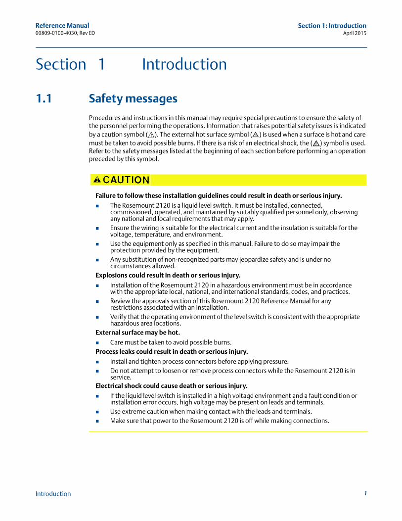
Procedures and instructions in this manual may require special precautions to ensure the safety of the personnel performing the operations. Information that raises potential safety issues is indicated by a caution symbol ( ). The external hot surface symbol ( ) is used when a surface is hot and care must be taken to avoid possible burns. If there is a risk of an electrical shock, the ( ) symbol is used. Refer to the safety messages listed at the beginning of each section before performing an operation preceded by this symbol.
Failure to follow these installation guidelines could result in death or serious injury.
The Rosemount 2120 is a liquid level switch. It must be installed, connected, commissioned, operated, and maintained by suitably qualified personnel only, observing any national and local requirements that may apply.
Ensure the wiring is suitable for the electrical current and the insulation is suitable for the voltage, temperature, and environment.
Use the equipment only as specified in this manual. Failure to do so may impair the protection provided by the equipment.
Any substitution of non-recognized parts may jeopardize safety and is under no circumstances allowed.
Explosions could result in death or serious injury.
Installation of the Rosemount 2120 in a hazardous environment must be in accordance with the appropriate local, national, and international standards, codes, and practices.
Review the approvals section of this Rosemount 2120 Reference Manual for any restrictions associated with an installation.
Verify that the operating environment of the level switch is consistent with the appropriate hazardous area locations.
External surface may be hot.
Care must be taken to avoid possible burns.Process leaks could result in death or serious injury.
Install and tighten process connectors before applying pressure. Do not attempt to loosen or remove process connectors while the Rosemount 2120 is in
service.Electrical shock could cause death or serious injury.
If the liquid level switch is installed in a high voltage environment and a fault condition or installation error occurs, high voltage may be present on leads and terminals.
Use extreme caution when making contact with the leads and terminals. Make sure that power to the Rosemount 2120 is off while making connections.
1Introduction
Reference Manual00809-0100-4030, Rev ED
Section 1: IntroductionApril 2015
2
1.2 Manual overview
This manual provides information on installing, operating, and maintaining the Rosemount 2120 Vibrating Fork Liquid Level Switch liquid level switch.
Section 2: Installation
Section 3: Service and Troubleshooting
Appendix A: Reference Data
Appendix B: Product Certifications
1.3 Models covered
All models of the Rosemount 2120 liquid level switch are covered in this manual.
1.4 Introduction to the Rosemount 2120
The Rosemount 2120 Vibrating Fork Liquid Level Switch is designed for use in process temperatures of –40 to 302 °F (–40 to 150 °C).
Based on vibrating short fork technology, the 2120 is suitable for virtually all liquid applications.
1.4.1 Features list
Features include:
Virtually unaffected by flow, bubbles, turbulence, foam, vibration, solids content, coating, properties of the liquid, and product variations
No need for calibration and requires minimum installation procedures
Easy terminal access and electrical protections (see page 40)
No moving parts or crevices means virtually no maintenance
A heartbeat LED gives status and instrument health information
Adjustable switching delay for turbulent or splashing applications
Magnetic test point for easy functional test
Short fork length with extensions up to 157.5 in. (4 m)
“Fast Drip” fork design gives quick response time
General area, Explosion-proof/Flameproof and Intrinsically Safe options
This combination of features makes the Rosemount 2120 an ideal choice for a wide variety of challenging applications in the chemical, power generation, and oil and gas industries.
See Figure 1-2 on page 5 for application examples.
Introduction
Reference Manual00809-0100-4030, Rev ED
Section 1: IntroductionApril 2015
1.4.2 Measurement principle
The Rosemount 2120 is designed using the principle of a tuning fork. A piezo-electric crystal oscillates the forks at their natural frequency. Changes to this frequency are continuously monitored. The frequency of the vibrating fork sensor changes depending on the medium in which it is immersed. The denser the liquid, the lower the frequency.
When used as a low level alarm, the liquid in the tank or pipe drains down past the fork, causing a change of natural frequency that is detected by the electronics and switches the output state.
When the Rosemount 2120 is used as a high level alarm, the liquid rises in the tank or pipe making contact with the fork and causing the output state to switch.
1.4.3 Short fork technology
The natural frequency (~1400 Hz) of the fork avoids interference from plant vibration that may cause false switching. This allows for minimum intrusion into the tank or pipe through the use of a short fork. Using Short Fork Technology, the Rosemount 2120 can be used in almost all liquid applications. Extensive research has maximized the operational effectiveness of the fork design, making it suitable for most liquids including coating liquids, aerated liquids, and slurries.
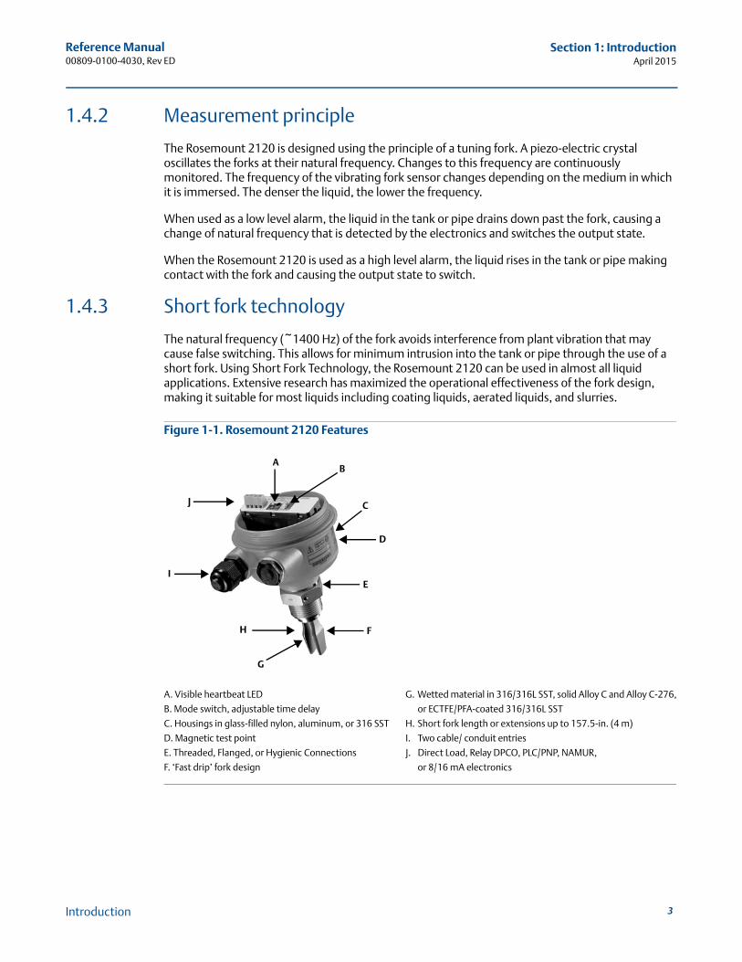
Figure 1-1. Rosemount 2120 Features
A. Visible heartbeat LED G. Wetted material in 316/316L SST, solid Alloy C and Alloy C-276,
B. Mode switch, adjustable time delay or ECTFE/PFA-coated 316/316L SST
C. Housings in glass-filled nylon, aluminum, or 316 SST H. Short fork length or extensions up to 157.5-in. (4 m)
D. Magnetic test point I. Two cable/ conduit entries
E. Threaded, Flanged, or Hygienic Connections J. Direct Load, Relay DPCO, PLC/PNP, NAMUR,
F. ‘Fast drip’ fork design or 8/16 mA electronics
F
BA
G
H
C
I
J
E
D
3Introduction

Reference Manual00809-0100-4030, Rev ED
Section 1: IntroductionApril 2015
4
1.4.4 Special features
Heartbeat LED
The Rosemount 2120 has a ‘heartbeat’ LED indicating its status, which can be seen at all times and from all angles through a lens in the cover of non-metal housings.
The LED flashes when the switch output is ‘off’ and is constantly lit when 'on'.
Fork design
The “fast drip” fork design draws liquid away from the fork tips when mounted horizontally, and together with a short switching delay, allows the Rosemount 2120 to react quickly and with greater sensitivity to density variations.
Mode switch and adjustable time delay
A mode switch allows the Rosemount 2120 to be set to switch from wet to dry (typically for low level alarm) or from dry to wet (typically for high level alarm). There is also a user-selectable time delay (0.3, 1, 3, 10, or 30 s) to virtually eliminate the risk of false switching in turbulent or splashing applications.
Magnetic test point
A magnetic test-point is located on the side of the housing, allowing the user to perform a functional test of the Rosemount 2120 and the system connected to it. Holding a magnet to the test-point causes the output to change state.
Electrical hookup
The terminal blocks extend above the housing and give easy terminal access. Electrical protections (see page 40) make electrical hook-up safe and easy.
Introduction
5
Reference Manual00809-0100-4030, Rev ED
Section 1: IntroductionApril 2015
Introduction
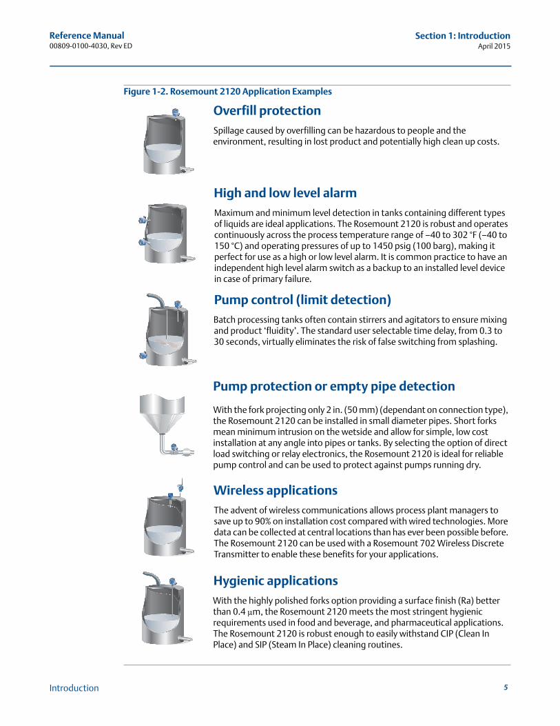
Figure 1-2. Rosemount 2120 Application Examples
Overfill protectionSpillage caused by overfilling can be hazardous to people and the environment, resulting in lost product and potentially high clean up costs.
High and low level alarmMaximum and minimum level detection in tanks containing different types of liquids are ideal applications. The Rosemount 2120 is robust and operates continuously across the process temperature range of –40 to 302 °F (–40 to 150 °C) and operating pressures of up to 1450 psig (100 barg), making it perfect for use as a high or low level alarm. It is common practice to have an independent high level alarm switch as a backup to an installed level device in case of primary failure.
Pump control (limit detection)Batch processing tanks often contain stirrers and agitators to ensure mixing and product ‘fluidity’. The standard user selectable time delay, from 0.3 to 30 seconds, virtually eliminates the risk of false switching from splashing.
Pump protection or empty pipe detection
With the fork projecting only 2 in. (50 mm) (dependant on connection type), the Rosemount 2120 can be installed in small diameter pipes. Short forks mean minimum intrusion on the wetside and allow for simple, low cost installation at any angle into pipes or tanks. By selecting the option of direct load switching or relay electronics, the Rosemount 2120 is ideal for reliable pump control and can be used to protect against pumps running dry.
Wireless applicationsThe advent of wireless communications allows process plant managers to save up to 90% on installation cost compared with wired technologies. More data can be collected at central locations than has ever been possible before. The Rosemount 2120 can be used with a Rosemount 702 Wireless Discrete Transmitter to enable these benefits for your applications.
Hygienic applicationsWith the highly polished forks option providing a surface finish (Ra) better than 0.4 μm, the Rosemount 2120 meets the most stringent hygienic requirements used in food and beverage, and pharmaceutical applications. The Rosemount 2120 is robust enough to easily withstand CIP (Clean In Place) and SIP (Steam In Place) cleaning routines.
2120 Vibrating Fork Level Switch
www.rosemount.com
2120 Vibrating Fo
rk Level Switch
www.ro
semount.co
m
2120 Vibrating Fo
rk Level Switch
www.ro
semount.co
m
2120 Vibrating Fork Level Switch
www.rosemount.com
2120 Vibrating Fo
rk Level Switch
www.ro
semount.co
m
2120 Vibrating Fork Level Switch
www.rosemount.com
2120 Vibrating Fork Level Switch
www.rosemount.com

Reference Manual00809-0100-4030, Rev ED
Section 1: IntroductionApril 2015
6
1.5 Service support
To expedite the return process outside of the United States, contact the nearest Emerson Process Management representative.
Within the United States, call the Emerson Process Management Instrument and Valves Response Center using the 1 800 654 7768 toll-free number. This center, available 24 hours a day, will assist you with any needed information or materials.
The center will ask for product model and serial numbers, and will provide a Return Material Authorization (RMA) number. The center will also ask for the process material to which the product was last exposed.
1.6 Product recycling and disposal
Recycling of equipment and packaging should be taken into consideration. The product and packaging should be disposed of in accordance with local and national legislation.
Individuals who handle products exposed to a hazardous substance can avoid injury if they are informed of, and understand, the hazard. If the product being returned was exposed to a hazardous substance as defined by OSHA, a copy of the required Material Safety Data Sheet (MSDS) for each hazardous substance identified must be included with the returned goods.
Introduction
Reference Manual00809-0100-4030, Rev ED
Section 2: InstallationApril 2015
Section 2 Installation
Safety messages . . . . . . . . . . . . . . . . . . . . . . . . . . . . . . . . . . . . . . . . . . . . . . . . . . . . . . . . . . . . . . page 7Considerations before installation . . . . . . . . . . . . . . . . . . . . . . . . . . . . . . . . . . . . . . . . . . . . . . page 8Installation procedures . . . . . . . . . . . . . . . . . . . . . . . . . . . . . . . . . . . . . . . . . . . . . . . . . . . . . . . . page 16Setting the mode switch and switching time delay . . . . . . . . . . . . . . . . . . . . . . . . . . . . . . . . page 20LED indication . . . . . . . . . . . . . . . . . . . . . . . . . . . . . . . . . . . . . . . . . . . . . . . . . . . . . . . . . . . . . . . . page 21Electrical installation . . . . . . . . . . . . . . . . . . . . . . . . . . . . . . . . . . . . . . . . . . . . . . . . . . . . . . . . . . page 22
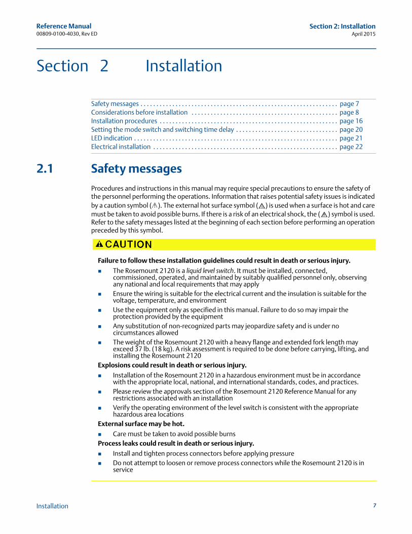
2.1 Safety messages
Procedures and instructions in this manual may require special precautions to ensure the safety of the personnel performing the operations. Information that raises potential safety issues is indicated by a caution symbol ( ). The external hot surface symbol ( ) is used when a surface is hot and care must be taken to avoid possible burns. If there is a risk of an electrical shock, the ( ) symbol is used. Refer to the safety messages listed at the beginning of each section before performing an operation preceded by this symbol.
Failure to follow these installation guidelines could result in death or serious injury.
The Rosemount 2120 is a liquid level switch. It must be installed, connected, commissioned, operated, and maintained by suitably qualified personnel only, observing any national and local requirements that may apply
Ensure the wiring is suitable for the electrical current and the insulation is suitable for the voltage, temperature, and environment
Use the equipment only as specified in this manual. Failure to do so may impair the protection provided by the equipment
Any substitution of non-recognized parts may jeopardize safety and is under no circumstances allowed
The weight of the Rosemount 2120 with a heavy flange and extended fork length may exceed 37 lb. (18 kg). A risk assessment is required to be done before carrying, lifting, and installing the Rosemount 2120
Explosions could result in death or serious injury.
Installation of the Rosemount 2120 in a hazardous environment must be in accordance with the appropriate local, national, and international standards, codes, and practices.
Please review the approvals section of the Rosemount 2120 Reference Manual for any restrictions associated with an installation
Verify the operating environment of the level switch is consistent with the appropriate hazardous area locations
External surface may be hot.
Care must be taken to avoid possible burnsProcess leaks could result in death or serious injury.
Install and tighten process connectors before applying pressure Do not attempt to loosen or remove process connectors while the Rosemount 2120 is in
service
7Installation
Reference Manual00809-0100-4030, Rev ED
Section 2: InstallationApril 2015
8
2.2 Considerations before installation
ImportantEmerson Process Management is not in a position to evaluate or guarantee the compatibility of the process fluid or other process parameters with the product, options, configuration or materials of construction selected.
2.2.1 Safety considerations
Safety instructions and control drawings specific to hazardous area installations are inAppendix B: Product Certifications, and there are safety instructions in the Rosemount 2120 Quick Start Guide (see www.rosemount.com for other language versions). These safety instructions also include general safety information.
2.2.2 Environmental considerations
The 2120 is a liquid level switch and is available as Intrinsically Safe (IS) or explosion-proof/flame-proof versions for hazardous area installations. There are also ordinary location versions for unclassified, safe areas. Approvals are listed in Appendix B: Product Certifications of this manual.
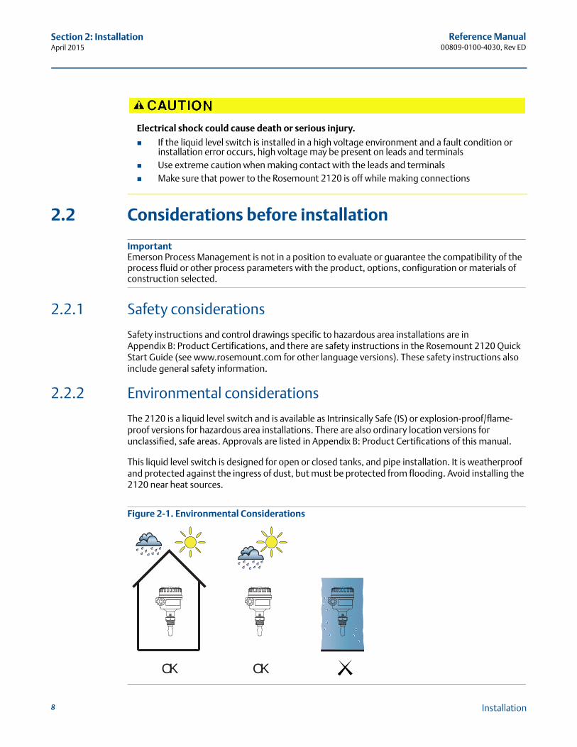
This liquid level switch is designed for open or closed tanks, and pipe installation. It is weatherproof and protected against the ingress of dust, but must be protected from flooding. Avoid installing the 2120 near heat sources.
Figure 2-1. Environmental Considerations
Electrical shock could cause death or serious injury.
If the liquid level switch is installed in a high voltage environment and a fault condition or installation error occurs, high voltage may be present on leads and terminals
Use extreme caution when making contact with the leads and terminals Make sure that power to the Rosemount 2120 is off while making connections
OKOK
Installation
Reference Manual00809-0100-4030, Rev ED
Section 2: InstallationApril 2015
2.2.3 Application considerations
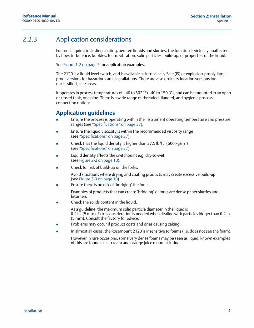
For most liquids, including coating, aerated liquids and slurries, the function is virtually unaffected by flow, turbulence, bubbles, foam, vibration, solid particles, build-up, or properties of the liquid.
See Figure 1-2 on page 5 for application examples.
The 2120 is a liquid level switch, and is available as Intrinsically Safe (IS) or explosion-proof/flame-proof versions for hazardous area installations. There are also ordinary location versions for unclassified, safe areas.
It operates in process temperatures of –40 to 302 °F (–40 to 150 °C), and can be mounted in an open or closed tank, or a pipe. There is a wide range of threaded, flanged, and hygienic process connection options.
Application guidelines Ensure the process is operating within the instrument operating temperature and pressure
ranges (see “Specifications” on page 37).
Ensure the liquid viscosity is within the recommended viscosity range(see “Specifications” on page 37).
Check that the liquid density is higher than 37.5 lb/ft3 (600 kg/m3)(see “Specifications” on page 37).
Liquid density affects the switchpoint e.g. dry-to-wet(see Figure 2-2 on page 10).
Check for risk of build-up on the forks.
Avoid situations where drying and coating products may create excessive build-up(see Figure 2-3 on page 10).
Ensure there is no risk of ‘bridging’ the forks.
Examples of products that can create ‘bridging’ of forks are dense paper slurries and bitumen.
Check the solids content in the liquid.
As a guideline, the maximum solid particle diameter in the liquid is 0.2 in. (5 mm). Extra consideration is needed when dealing with particles bigger than 0.2 in. (5 mm). Consult the factory for advice.
Problems may occur if product coats and dries causing caking.
In almost all cases, the Rosemount 2120 is insensitive to foams (i.e. does not see the foam).
However in rare occasions, some very dense foams may be seen as liquid; known examples of this are found in ice-cream and orange juice manufacturing.
9Installation
Reference Manual00809-0100-4030, Rev ED
Section 2: InstallationApril 2015
10
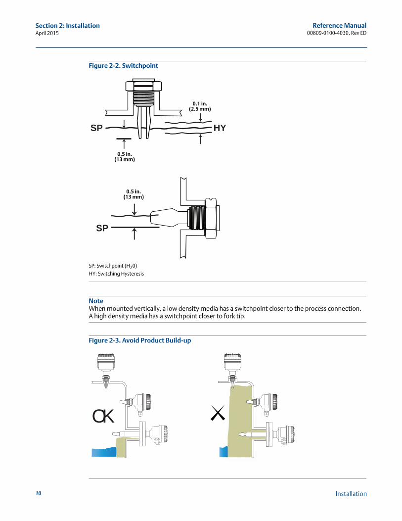
Figure 2-2. Switchpoint
SP: Switchpoint (H20)
HY: Switching Hysteresis
NoteWhen mounted vertically, a low density media has a switchpoint closer to the process connection.A high density media has a switchpoint closer to fork tip.
Figure 2-3. Avoid Product Build-up
SP
HYSP
0.1 in.(2.5 mm)
0.5 in.(13 mm)
0.5 in.(13 mm)
OK
Installation
Reference Manual00809-0100-4030, Rev ED
Section 2: InstallationApril 2015
2.2.4 Installation considerations
For dimensional drawings, see “Dimensional drawings” on page 42.
Device identification
To identify the Rosemount 2120 version, see the labels on the housing and on the electronics cassette inside the housing. See Appendix B: Product Certifications for approval information.
Allow adequate space outside tank or pipe
Mount the switch so that it is removable. Clearance of 1.2 in. (30 mm) is required for cover removal. Ensure there is sufficient room for electrical connections. The glass-filled nylon housing can be rotated to assist with the cabling, but the metal housings cannot be rotated.
Fit the cover correctly
Ensure the housing O-ring is sitting evenly and then tighten the housing cover to form a good seal. Always use Rosemount O-rings.
Grounding on metal housings
Always ground the housing in accordance with national and local electrical codes.
The most effective grounding method for the metal housing is a direct connection to earth ground with minimal impedance. Housings with NPT conduit entries do not have an earth ground point and must use the fork earth.
How to handle the Rosemount 2120
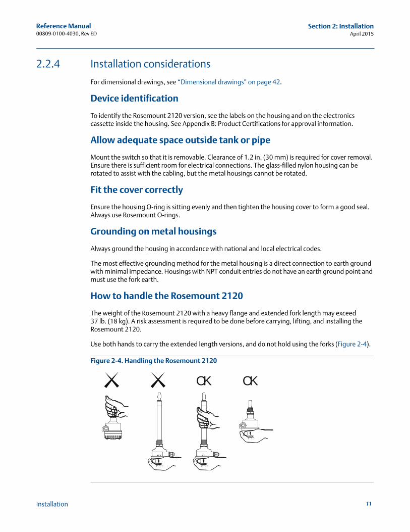
The weight of the Rosemount 2120 with a heavy flange and extended fork length may exceed37 lb. (18 kg). A risk assessment is required to be done before carrying, lifting, and installing the Rosemount 2120.
Use both hands to carry the extended length versions, and do not hold using the forks (Figure 2-4).
Figure 2-4. Handling the Rosemount 2120
OK OK
11Installation
Reference Manual00809-0100-4030, Rev ED
Section 2: InstallationApril 2015
12
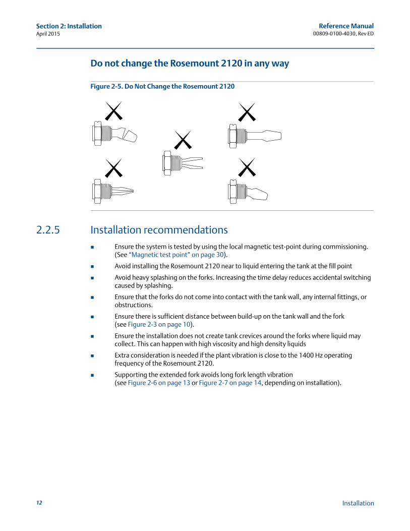
Do not change the Rosemount 2120 in any way
Figure 2-5. Do Not Change the Rosemount 2120
2.2.5 Installation recommendations Ensure the system is tested by using the local magnetic test-point during commissioning.
(See “Magnetic test point” on page 30).
Avoid installing the Rosemount 2120 near to liquid entering the tank at the fill point
Avoid heavy splashing on the forks. Increasing the time delay reduces accidental switching caused by splashing.
Ensure that the forks do not come into contact with the tank wall, any internal fittings, or obstructions.
Ensure there is sufficient distance between build-up on the tank wall and the fork(see Figure 2-3 on page 10).
Ensure the installation does not create tank crevices around the forks where liquid may collect. This can happen with high viscosity and high density liquids
Extra consideration is needed if the plant vibration is close to the 1400 Hz operating frequency of the Rosemount 2120.
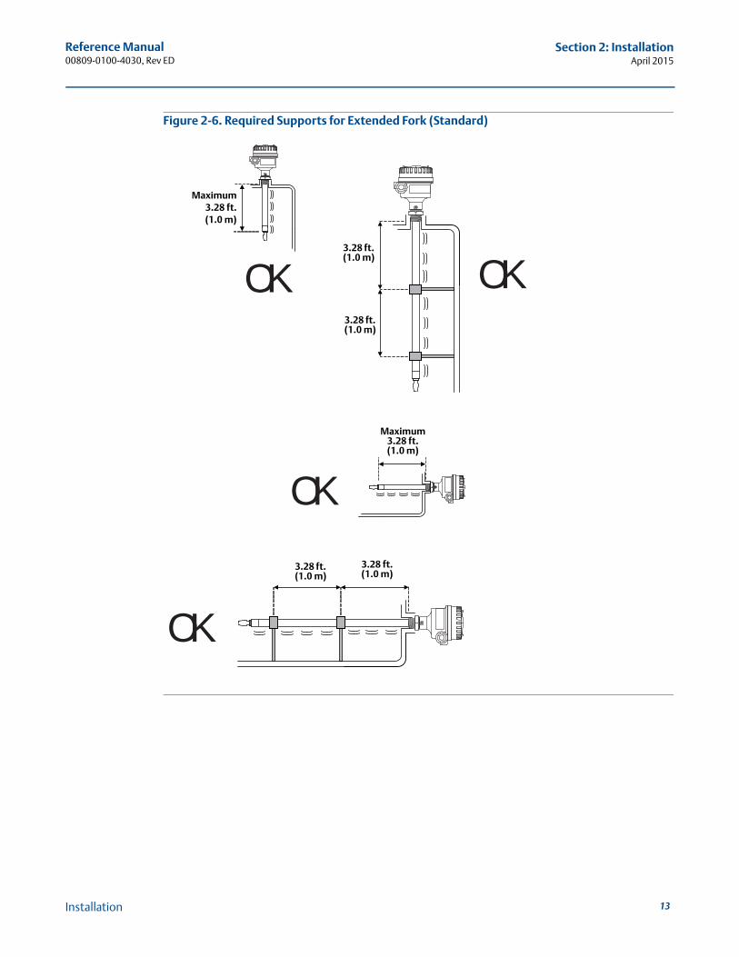
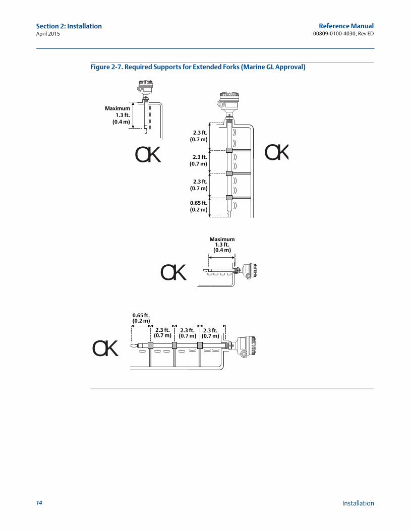
Supporting the extended fork avoids long fork length vibration(see Figure 2-6 on page 13 or Figure 2-7 on page 14, depending on installation).
Installation
Reference Manual00809-0100-4030, Rev ED
Section 2: InstallationApril 2015
Figure 2-6. Required Supports for Extended Fork (Standard)
OK
OK
OK
OK
3.28 ft. (1.0 m)
3.28 ft. (1.0 m)
Maximum3.28 ft.(1.0 m)
3.28 ft. (1.0 m)
3.28 ft. (1.0 m)
Maximum 3.28 ft. (1.0 m)
13Installation
Reference Manual00809-0100-4030, Rev ED
Section 2: InstallationApril 2015
14
Figure 2-7. Required Supports for Extended Forks (Marine GL Approval)
OK
OK
OK
OK
2.3 ft. (0.7 m)
0.65 ft. (0.2 m)
Maximum1.3 ft.
(0.4 m)
0.65 ft.(0.2 m)
2.3 ft.(0.7 m)
Maximum 1.3 ft.
(0.4 m)
2.3 ft.(0.7 m)
2.3 ft.(0.7 m)
2.3 ft. (0.7 m)
2.3 ft. (0.7 m)
Installation
15
Reference Manual00809-0100-4030, Rev ED
Section 2: InstallationApril 2015
Installation
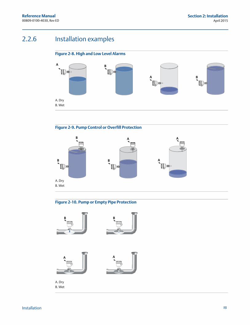
2.2.6 Installation examples
Figure 2-8. High and Low Level Alarms
A. Dry
B. Wet
Figure 2-9. Pump Control or Overfill Protection
A. Dry
B. Wet
Figure 2-10. Pump or Empty Pipe Protection
A. Dry
B. Wet
A B
A B
B B
B A A
A
A
B B
A
Reference Manual00809-0100-4030, Rev ED
Section 2: InstallationApril 2015
16
2.3 Installation procedures
2.3.1 Mechanical
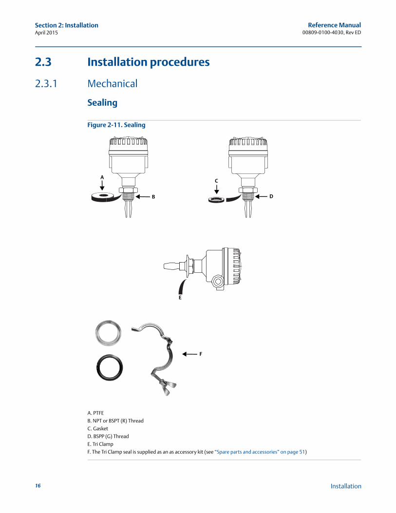
Sealing
Figure 2-11. Sealing
A. PTFE
B. NPT or BSPT (R) Thread
C. Gasket
D. BSPP (G) Thread
E. Tri Clamp
F. The Tri Clamp seal is supplied as an as accessory kit (see “Spare parts and accessories” on page 51)
AC
B D
E
F
Installation
Reference Manual00809-0100-4030, Rev ED
Section 2: InstallationApril 2015
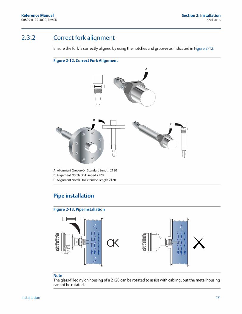
2.3.2 Correct fork alignment
Ensure the fork is correctly aligned by using the notches and grooves as indicated in Figure 2-12.
Figure 2-12. Correct Fork Alignment
A. Alignment Groove On Standard Length 2120
B. Alignment Notch On Flanged 2120
C. Alignment Notch On Extended Length 2120
Pipe installation
Figure 2-13. Pipe Installation
NoteThe glass-filled nylon housing of a 2120 can be rotated to assist with cabling, but the metal housing cannot be rotated.
A
BC
OK
17Installation
Reference Manual00809-0100-4030, Rev ED
Section 2: InstallationApril 2015
18
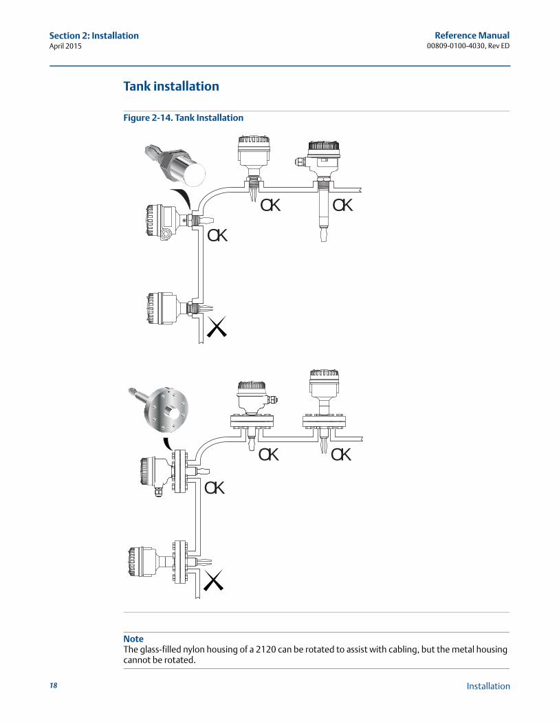
Tank installation
Figure 2-14. Tank Installation
NoteThe glass-filled nylon housing of a 2120 can be rotated to assist with cabling, but the metal housing cannot be rotated.
OKOK
OK
OK OK
OK
Installation
Reference Manual00809-0100-4030, Rev ED
Section 2: InstallationApril 2015
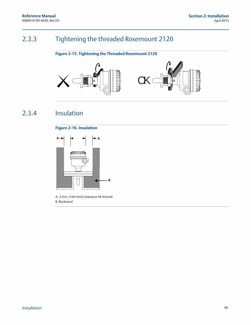
2.3.3 Tightening the threaded Rosemount 2120
Figure 2-15. Tightening the Threaded Rosemount 2120
2.3.4 Insulation
Figure 2-16. Insulation
A. 3.9 in. (100 mm) Clearance All Around
B. Rockwool
OK
A
B
A
19Installation
Reference Manual00809-0100-4030, Rev ED
Section 2: InstallationApril 2015
20
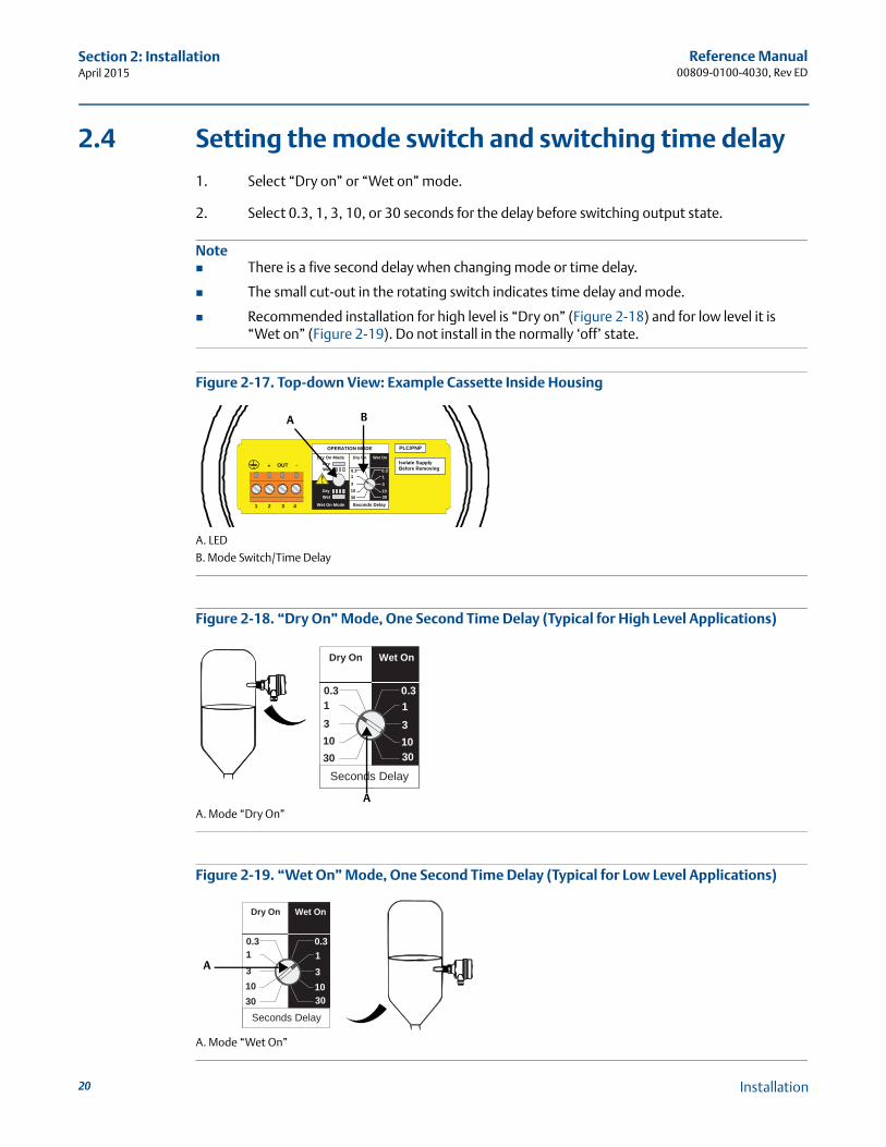
2.4 Setting the mode switch and switching time delay
1. Select “Dry on” or “Wet on” mode.
2. Select 0.3, 1, 3, 10, or 30 seconds for the delay before switching output state.
Note There is a five second delay when changing mode or time delay.
The small cut-out in the rotating switch indicates time delay and mode.
Recommended installation for high level is “Dry on” (Figure 2-18) and for low level it is“Wet on” (Figure 2-19). Do not install in the normally ‘off’ state.
Figure 2-17. Top-down View: Example Cassette Inside Housing
A. LED
B. Mode Switch/Time Delay
Figure 2-18. “Dry On” Mode, One Second Time Delay (Typical for High Level Applications)
A. Mode “Dry On”
Figure 2-19. “Wet On” Mode, One Second Time Delay (Typical for Low Level Applications)
A. Mode “Wet On”
OPERATION MODE
Dry On ModeDryWet
Wet On Mode
DryWet
Dry On Wet On
Seconds Delay
0.3 0.3
3
3010
1
3
3010
1
1 2 3
OUT+ -
4
PLC/PNP
Isolate SupplyBefore Removing
BA
Dry On Wet On
Seconds Delay
0.3 0.3
3
3010
1
3
3010
1
A
Dry On Wet On
Seconds Delay
0.3 0.3
3010
3
3010
131
A
Installation
Reference Manual00809-0100-4030, Rev ED
Section 2: InstallationApril 2015
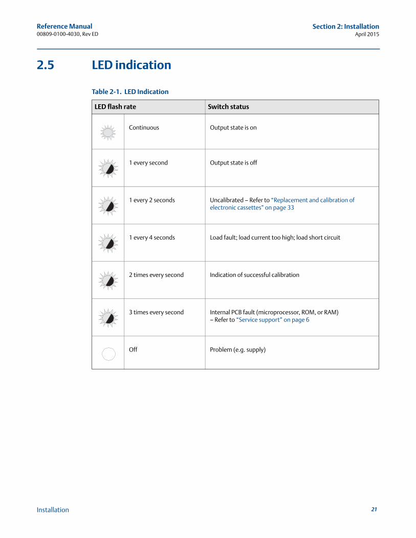
2.5 LED indication
Table 2-1. LED Indication
LED flash rate Switch status
Continuous Output state is on
1 every second Output state is off
1 every 2 seconds Uncalibrated – Refer to “Replacement and calibration of electronic cassettes” on page 33
1 every 4 seconds Load fault; load current too high; load short circuit
2 times every second Indication of successful calibration
3 times every second Internal PCB fault (microprocessor, ROM, or RAM)– Refer to “Service support” on page 6
Off Problem (e.g. supply)
21Installation
Reference Manual00809-0100-4030, Rev ED
Section 2: InstallationApril 2015
22
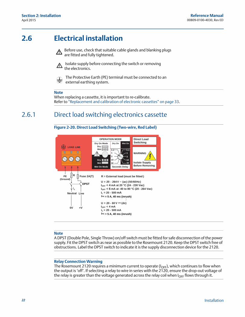
2.6 Electrical installation
Before use, check that suitable cable glands and blanking plugsare fitted and fully tightened.
Isolate supply before connecting the switch or removingthe electronics.
The Protective Earth (PE) terminal must be connected to anexternal earthing system.
NoteWhen replacing a cassette, it is important to re-calibrate.Refer to “Replacement and calibration of electronic cassettes” on page 33.
2.6.1 Direct load switching electronics cassette
Figure 2-20. Direct Load Switching (Two-wire, Red Label)
NoteA DPST (Double Pole, Single Throw) on/off switch must be fitted for safe disconnection of the power supply. Fit the DPST switch as near as possible to the Rosemount 2120. Keep the DPST switch free of obstructions. Label the DPST switch to indicate it is the supply disconnection device for the 2120.
Relay Connection WarningThe Rosemount 2120 requires a minimum current to operate (IOFF), which continues to flow when the output is ‘off’. If selecting a relay to wire in series with the 2120, ensure the drop-out voltage of the relay is greater than the voltage generated across the relay coil when IOFF flows through it.
Direct LoadSwitching
WARNING
Isolate SupplyBefore Removing
OPERATION MODEDry On Mode
DryWet
Wet On Mode
DryWet
Dry On Wet On
Seconds Delay
0.3 0.3
3
3010
1
3
3010
1
1 2 3
LINELOAD
PE(Ground)
Neutral Live
0V
Fuse 2A(T)R
IL
R = External load (must be fitted )
U = 20 - 264V ~ (ac) (50/60Hz)IOFF < 4 mA at 20 °C (24 - 230 Vac)IOFF < 6 mA at -40 to 80 °C (20 - 264 Vac)IL = 20 - 500 mA
U = 20 - 60 V (dc))
IOFF < 4 mAIL = 20 - 500 mA
DPST
+V
= 5 A, 40 ms (inrush)IPK
= 5 A, 40 ms (inrush)IPK
Installation
Reference Manual00809-0100-4030, Rev ED
Section 2: InstallationApril 2015
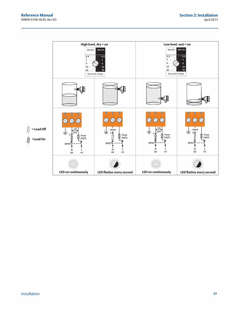
High level, dry = on Low level, wet = on
LED on continuously LED flashes every second LED on continuously LED flashes every second
=Load On
= Load Off
Dry On Wet On
Seconds Delay
0.3 0.3
3
3010
1
3
3010
1
Dry On Wet On
Seconds Delay
0.3 0.3
3010
3
3010
131
U
N L0V +V
Fuse2A(T)
IL12V
DPST
Fuse2A(T)
N L0V +V
IL<4mA
DPST
U
N L0V +V
Fuse2A(T)
IL12V
DPST
Fuse2A(T)
N L0V +V
IL<4mA
DPST
23Installation
Reference Manual00809-0100-4030, Rev ED
Section 2: InstallationApril 2015
24
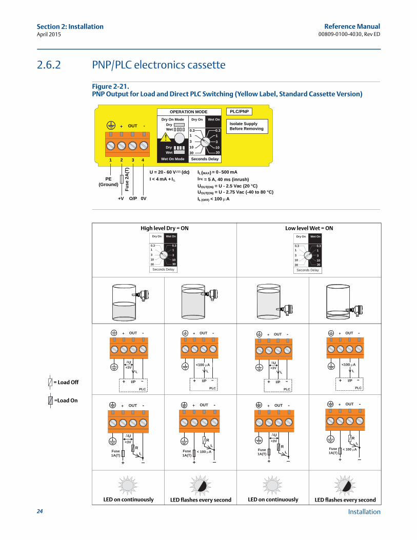
2.6.2 PNP/PLC electronics cassette
Figure 2-21. PNP Output for Load and Direct PLC Switching (Yellow Label, Standard Cassette Version)
High level Dry = ON Low level Wet = ON
LED on continuously LED flashes every second LED on continuously LED flashes every second
OPERATION MODE
Dry On ModeDryWet
Wet On Mode
DryWet
Dry On Wet On
Seconds Delay
0.3 0.3
3
3010
1
3
3010
1
1 2 3
OUT+ -
4
PLC/PNP
Isolate SupplyBefore Removing
PE(Ground)
0VO/P
U = 20 - 60 V (dc)I < 4 mA + IL
+V
Fuse
2A
(T)
IL (MAX) = 0 - 500 mA
UOUT(ON) = U - 2.5 Vac (20 °C)
IL (OFF) < 100A
= 5 A, 40 ms (inrush)IPK
UOUT(ON) = U - 2.75 Vac (-40 to 80 °C)
Dry On Wet On
Seconds Delay
0.3 0.3
3
3010
1
3
3010
1
Dry On Wet On
Seconds Delay
0.3 0.3
3010
3
3010
131
OUT -+
PLC
+ I/P
U<3V
IL
OUT -+
PLC
+ I/P
IL
<100 A
OUT -+
PLC
+ I/P
U<3V
IL
OUT -+
PLC
+ I/P
IL
<100 A
OUT -+
+
U<3V
ILFuse1A(T)
R
OUT -+
+
ILFuse1A(T)
R
< 100 A
OUT -+
+
U<3V
ILFuse1A(T)
R
OUT -+
+
ILFuse1A(T)
R
< 100 A
=Load On
= Load Off
Installation
Reference Manual00809-0100-4030, Rev ED
Section 2: InstallationApril 2015
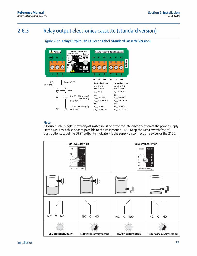
2.6.3 Relay output electronics cassette (standard version)
Figure 2-22. Relay Output, DPCO (Green Label, Standard Cassette Version)
NoteA Double Pole, Single Throw on/off switch must be fitted for safe disconnection of the power supply. Fit the DPST switch as near as possible to the Rosemount 2120. Keep the DPST switch free of obstructions. Label the DPST switch to indicate it is the supply disconnection device for the 2120.
High level, dry = on Low level, wet = on
LED on continuously LED flashes every second LED on continuously LED flashes every second
NC C NONC NO
7 8 9
NOCNC
REL
AY
1 2 3
LN
4 5 6
NOCNC
OPERATION MODEDry On
DryWet
Wet On
DryWet
Dry On Wet OnSeconds Delay
3010
31
0.3 0.3
3010
31
Isolate Supply Before Removing Warning
C
Resistive Loadcos φ = 1 ;L/R = 0 ms
ac:
dc:
Inductive LoadFuse 0.5 (T)PE(Ground)
DPST
N
0V +V
Live U = 20...264 V ~ (ac) (50/60 Hz)
U = 20...60 V (dc)
I < 6 mA
I < 6 mA
IMAX = 5 A
UMAX = 250 VPMAX = 1250 VA
UMAX = 30 VPMAX = 240 W
cos φ = 0.4 ;L/R = 7 ms
ac:
dc:
IMAX = 3.5 A
UMAX = 250 VPMAX = 875 VA
UMAX = 30 VPMAX = 170 W
Dry On Wet On
Seconds Delay
0.3 0.3
3
3010
1
3
3010
1
Dry On Wet On
Seconds Delay
0.3 0.3
3010
3
3010
131
NC NOC NC NOC NC NOC NC NOC
25Installation
Reference Manual00809-0100-4030, Rev ED
Section 2: InstallationApril 2015
26
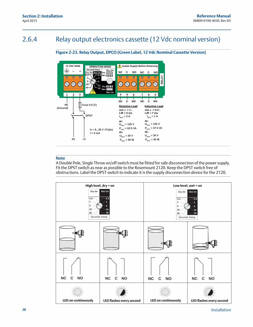
2.6.4 Relay output electronics cassette (12 Vdc nominal version)
Figure 2-23. Relay Output, DPCO (Green Label, 12 Vdc Nominal Cassette Version)
NoteA Double Pole, Single Throw on/off switch must be fitted for safe disconnection of the power supply. Fit the DPST switch as near as possible to the Rosemount 2120. Keep the DPST switch free of obstructions. Label the DPST switch to indicate it is the supply disconnection device for the 2120.
High level, dry = on Low level, wet = on
LED on continuously LED flashes every second LED on continuously LED flashes every second
NC C NONC NO
7 8 9
NOCNC
REL
AY
1 2 3
+
4 5 6
NOCNC
OPERATION MODEDry On
DryWet
Wet On
DryWet
Dry On Wet OnSeconds Delay
3010
31
0.3 0.3
3010
31
Isolate Supply Before Removing12 VDC NOM.
C
Resistive Loadcos φ = 1 ;L/R = 0 ms
ac:
dc:
Inductive LoadFuse 0.5 (T)PE(Ground)
DPST
0V +V
U = 9...30 V (dc)I < 4 mA
IMAX = 2 A
UMAX = 125 VPMAX = 62.5 VA
UMAX = 30 VPMAX = 60 W
cos φ = 0.4 ;L/R = 7 ms
ac:
dc:
IMAX = 1 A
UMAX = 125 VPMAX = 37.5 VA
UMAX = 30 VPMAX = 30 W
Dry On Wet On
Seconds Delay
0.3 0.3
3
3010
1
3
3010
1
Dry On Wet On
Seconds Delay
0.3 0.3
3010
3
3010
131
NC NOC NC NOC NC NOC NC NOC
Installation
Reference Manual00809-0100-4030, Rev ED
Section 2: InstallationApril 2015
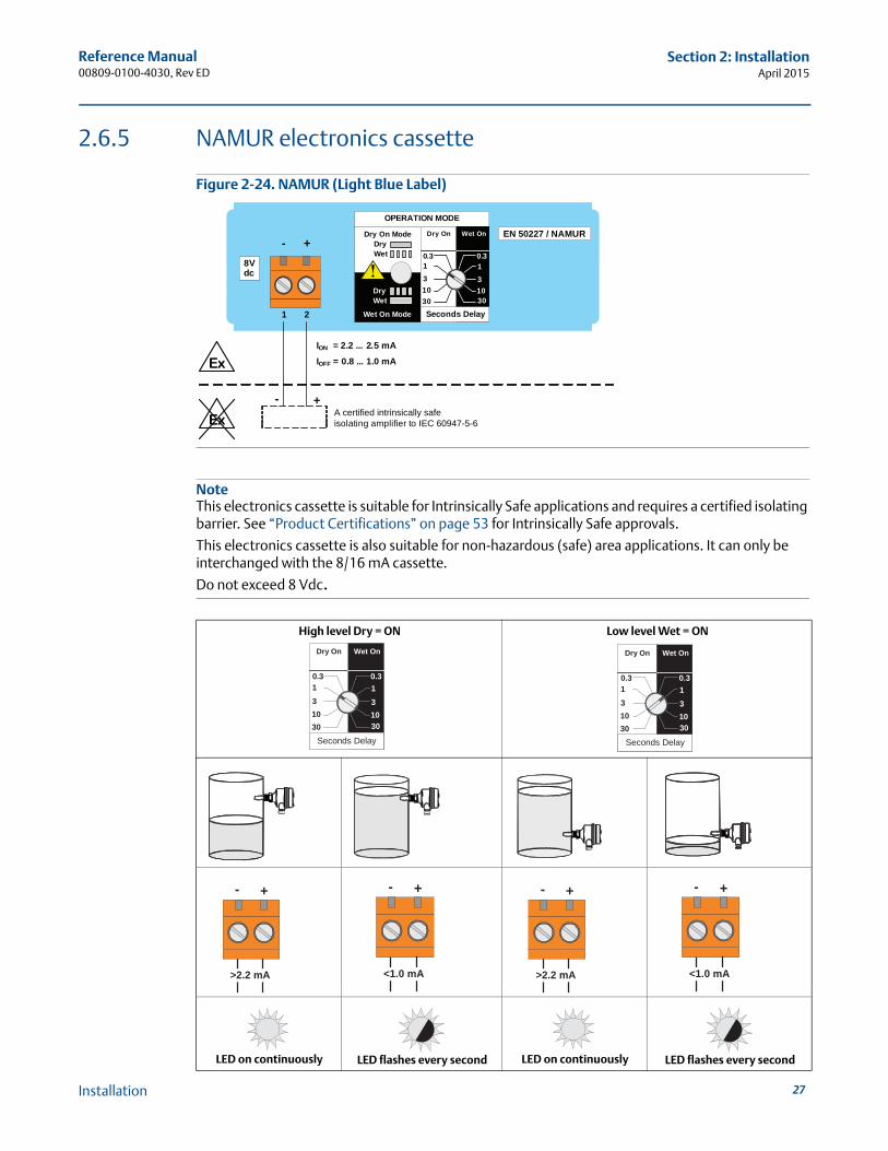
2.6.5 NAMUR electronics cassette
Figure 2-24. NAMUR (Light Blue Label)
NoteThis electronics cassette is suitable for Intrinsically Safe applications and requires a certified isolating barrier. See “Product Certifications” on page 53 for Intrinsically Safe approvals.
This electronics cassette is also suitable for non-hazardous (safe) area applications. It can only be interchanged with the 8/16 mA cassette.
Do not exceed 8 Vdc.
High level Dry = ON Low level Wet = ON
LED on continuously LED flashes every second LED on continuously LED flashes every second
OPERATION MODE
Dry On ModeDryWet
Wet On Mode
DryWet
Dry On Wet On
Seconds Delay
0.3 0.3
3
3010
1
3
3010
1
1 2
+-EN 50227 / NAMUR
ION = 2.2 ... 2.5 mAIOFF = 0.8 ... 1.0 mA
+-A certified intrinsically safe isolating amplifier to IEC 60947-5-6
Ex
Ex
8Vdc
Dry On Wet On
Seconds Delay
0.3 0.3
3
3010
1
3
3010
1
Dry On Wet On
Seconds Delay
0.3 0.3
3010
3
3010
131
+-
>2.2 mA
+-
<1.0 mA
+-
>2.2 mA
+-
<1.0 mA
27Installation
Reference Manual00809-0100-4030, Rev ED
Section 2: InstallationApril 2015
28
2.6.6 8/16 mA electronics cassette
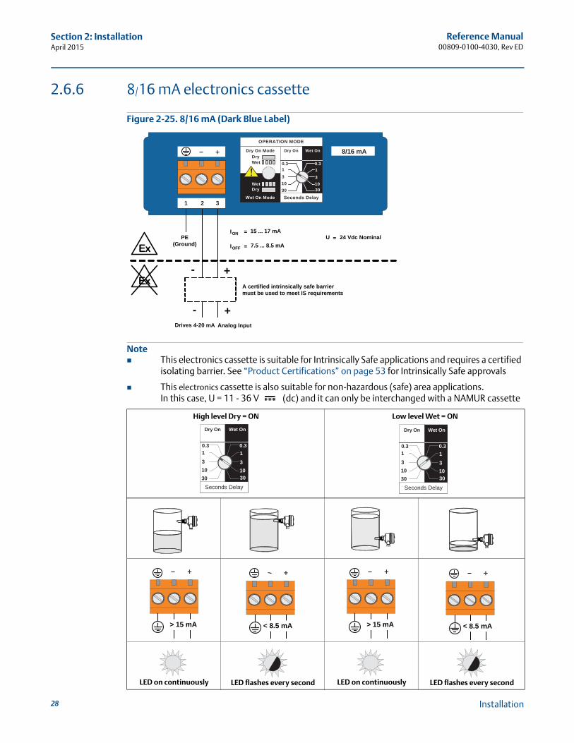
Figure 2-25. 8/16 mA (Dark Blue Label)
Note This electronics cassette is suitable for Intrinsically Safe applications and requires a certified
isolating barrier. See “Product Certifications” on page 53 for Intrinsically Safe approvals
This electronics cassette is also suitable for non-hazardous (safe) area applications.In this case, U = 11 - 36 V (dc) and it can only be interchanged with a NAMUR cassette
High level Dry = ON Low level Wet = ON
LED on continuously LED flashes every second LED on continuously LED flashes every second
OPERATION MODE
Dry On ModeDryWet
Wet On Mode
DryWet
Dry On Wet On
Seconds Delay
0.3 0.3
3
3010
13
3010
1
8/16 mA
1 2 3
+
Drives 4-20 mA Analog Input
ION =
IOFF =
+-
+
A certified intrinsically safe barriermust be used to meet IS requirements
Ex
Ex
15 ... 17 mA
7.5 ... 8.5 mA
-
PE(Ground)
U = 24 Vdc Nominal
Dry On Wet On
Seconds Delay
0.3 0.3
3
3010
1
3
3010
1
Dry On Wet On
Seconds Delay
0.3 0.3
3010
3
3010
131
+
> 15 mA
+
< 8.5 mA
+
> 15 mA
+
< 8.5 mA
Installation
Reference Manual00809-0100-4030, Rev ED
Section 3: Service and TroubleshootingApril 2015
Section 3 Service and Troubleshooting
Safety messages . . . . . . . . . . . . . . . . . . . . . . . . . . . . . . . . . . . . . . . . . . . . . . . . . . . . . . . . . . . . . . page 29Magnetic test point . . . . . . . . . . . . . . . . . . . . . . . . . . . . . . . . . . . . . . . . . . . . . . . . . . . . . . . . . . . page 30Inspection . . . . . . . . . . . . . . . . . . . . . . . . . . . . . . . . . . . . . . . . . . . . . . . . . . . . . . . . . . . . . . . . . . . page 31Maintenance . . . . . . . . . . . . . . . . . . . . . . . . . . . . . . . . . . . . . . . . . . . . . . . . . . . . . . . . . . . . . . . . . page 31Spare parts . . . . . . . . . . . . . . . . . . . . . . . . . . . . . . . . . . . . . . . . . . . . . . . . . . . . . . . . . . . . . . . . . . page 32Troubleshooting . . . . . . . . . . . . . . . . . . . . . . . . . . . . . . . . . . . . . . . . . . . . . . . . . . . . . . . . . . . . . . page 32Replacement and calibration of electronic cassettes . . . . . . . . . . . . . . . . . . . . . . . . . . . . . . . page 33
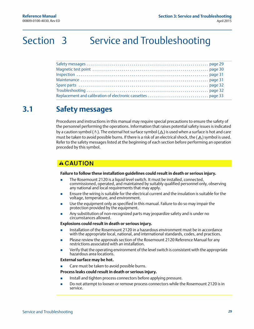
3.1 Safety messages
Procedures and instructions in this manual may require special precautions to ensure the safety of the personnel performing the operations. Information that raises potential safety issues is indicated by a caution symbol ( ). The external hot surface symbol ( ) is used when a surface is hot and care must be taken to avoid possible burns. If there is a risk of an electrical shock, the ( ) symbol is used. Refer to the safety messages listed at the beginning of each section before performing an operation preceded by this symbol.
Failure to follow these installation guidelines could result in death or serious injury.
The Rosemount 2120 is a liquid level switch. It must be installed, connected, commissioned, operated, and maintained by suitably qualified personnel only, observing any national and local requirements that may apply.
Ensure the wiring is suitable for the electrical current and the insulation is suitable for the voltage, temperature, and environment.
Use the equipment only as specified in this manual. Failure to do so may impair the protection provided by the equipment.
Any substitution of non-recognized parts may jeopardize safety and is under no circumstances allowed.
Explosions could result in death or serious injury.
Installation of the Rosemount 2120 in a hazardous environment must be in accordance with the appropriate local, national, and international standards, codes, and practices.
Please review the approvals section of the Rosemount 2120 Reference Manual for any restrictions associated with an installation.
Verify that the operating environment of the level switch is consistent with the appropriate hazardous area locations.
External surface may be hot.
Care must be taken to avoid possible burns.Process leaks could result in death or serious injury.
Install and tighten process connectors before applying pressure. Do not attempt to loosen or remove process connectors while the Rosemount 2120 is in
service.
29Service and Troubleshooting
Reference Manual00809-0100-4030, Rev ED
Section 3: Service and TroubleshootingApril 2015
30
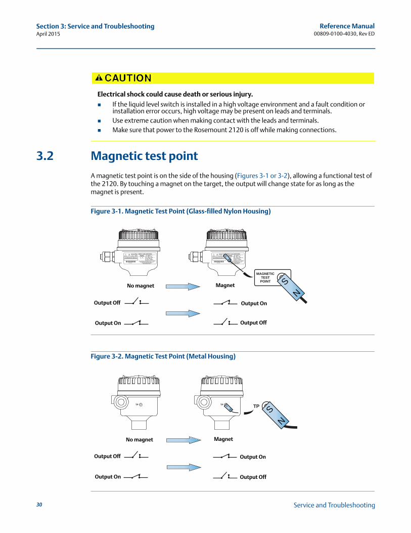
3.2 Magnetic test point
A magnetic test point is on the side of the housing (Figures 3-1 or 3-2), allowing a functional test of the 2120. By touching a magnet on the target, the output will change state for as long as the magnet is present.
Figure 3-1. Magnetic Test Point (Glass-filled Nylon Housing)
Figure 3-2. Magnetic Test Point (Metal Housing)
Electrical shock could cause death or serious injury.
If the liquid level switch is installed in a high voltage environment and a fault condition or installation error occurs, high voltage may be present on leads and terminals.
Use extreme caution when making contact with the leads and terminals. Make sure that power to the Rosemount 2120 is off while making connections.
~20 - 264Vac50 - 60Hz 2VA20 - 60Vdc 0.5WOutput Rating:Load 20 - 500mA
Supply
www.rosemount.com
MAX PROCESS TEMPERATURE: 150°C MADE IN UNITED KINGDOM
MAX WORKING PRESSURE AT 20°C: 0.25 bar
DIRECT LOAD SWITCHINGMAGNETICTEST POINT
41001029*41001029*
2120D0AS1NAAA
~20 - 264Vac50 - 60Hz 2VA20 - 60Vdc 0.5WOutput Rating:Load 20 - 500mA
Supply
www.rosemount.com
MAX PROCESS TEMPERATURE: 150°C MADE IN UNITED KINGDOM
MAX WORKING PRESSURE AT 20°C: 0.25 bar
DIRECT LOAD SWITCHINGMAGNETICTEST POINT
41001029*41001029*
2120D0AS1NAAA
MAGNETICTEST POINT S
N
SN
Output Off
Output Off
Output On
Output On
No magnet Magnet
TP TP TP
SN
SN
Output Off
Output Off
Output On
Output On
No magnet Magnet
Service and Troubleshooting
Reference Manual00809-0100-4030, Rev ED
Section 3: Service and TroubleshootingApril 2015
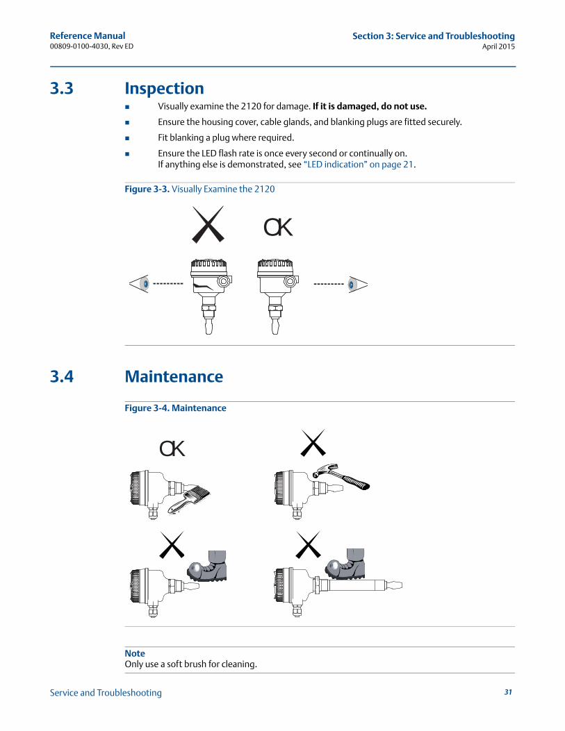
3.3 Inspection Visually examine the 2120 for damage. If it is damaged, do not use.
Ensure the housing cover, cable glands, and blanking plugs are fitted securely.
Fit blanking a plug where required.
Ensure the LED flash rate is once every second or continually on.If anything else is demonstrated, see “LED indication” on page 21.
Figure 3-3. Visually Examine the 2120
3.4 Maintenance
Figure 3-4. Maintenance
NoteOnly use a soft brush for cleaning.
OK
OK
31Service and Troubleshooting
Reference Manual00809-0100-4030, Rev ED
Section 3: Service and TroubleshootingApril 2015
32
3.5 Spare parts
See Spare parts and accessories on page 51.
3.6 Troubleshooting
If there is a malfunction, see Table 3-1 for information on possible causes.
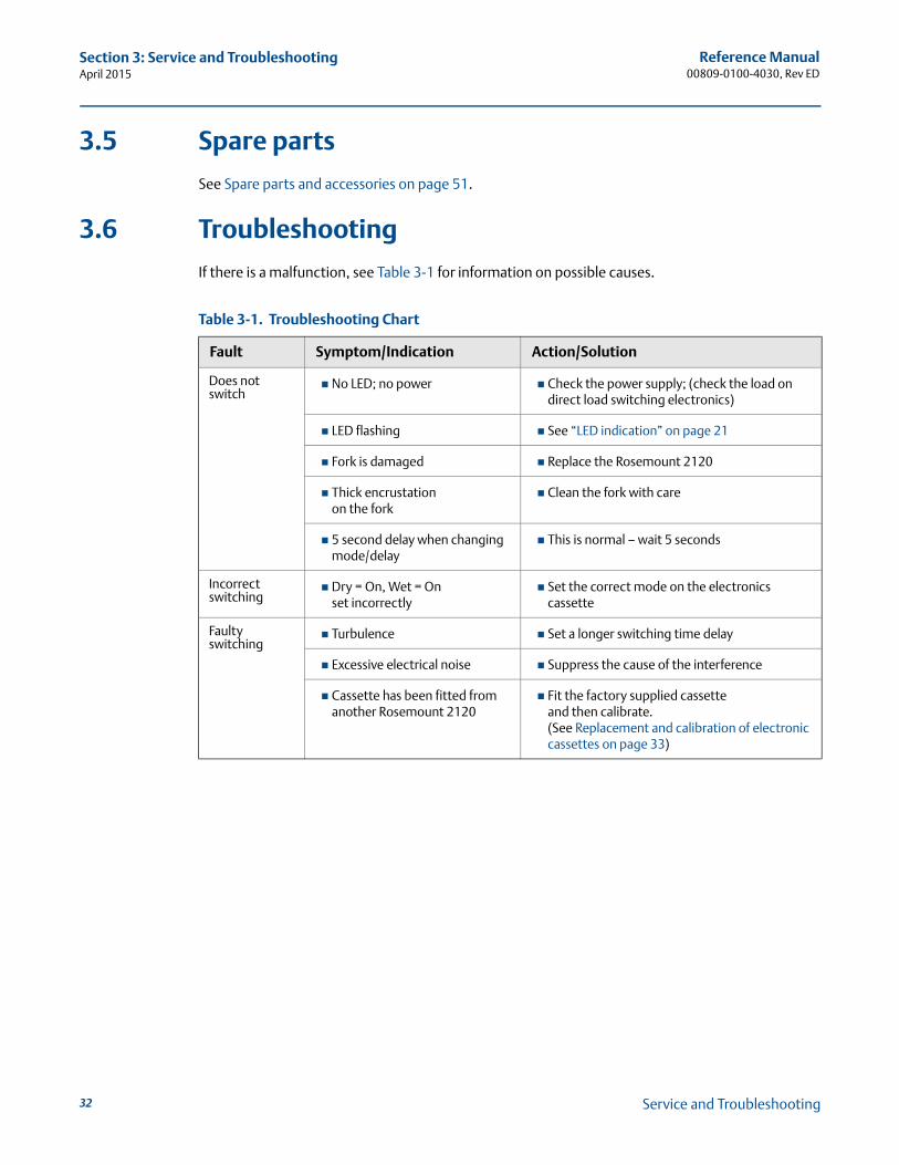
Table 3-1. Troubleshooting Chart
Fault Symptom/Indication Action/Solution
Does not switch
No LED; no power Check the power supply; (check the load on direct load switching electronics)
LED flashing See “LED indication” on page 21
Fork is damaged Replace the Rosemount 2120
Thick encrustationon the fork
Clean the fork with care
5 second delay when changing mode/delay
This is normal – wait 5 seconds
Incorrect switching
Dry = On, Wet = Onset incorrectly
Set the correct mode on the electronics cassette
Faultyswitching
Turbulence Set a longer switching time delay
Excessive electrical noise Suppress the cause of the interference
Cassette has been fitted from another Rosemount 2120
Fit the factory supplied cassetteand then calibrate.(See Replacement and calibration of electronic cassettes on page 33)
Service and Troubleshooting
Reference Manual00809-0100-4030, Rev ED
Section 3: Service and TroubleshootingApril 2015
3.7 Replacement and calibration of electronic cassettes
When replacing a damaged or faulty electronic cassette, calibrate the replacement cassette to the operating frequency of the fork assembly.
This section describes what is required for calibration. Calibration sequence steps 3 to 13 are time dependent and must be carried out within the noted times. The purpose of the time dependency and switching sequence is to prevent an accidental calibration from occurring.
If this replacement is taking place in a hazardous area, only qualified personnel should perform the replacement. All work in hazardous areas must be carried out in accordance with the local code. For general hazardous area requirements of this equipment, refer to Appendix B: Product Certifications.
Calibration of the device is complex and it may take several attempts before calibration is successful.
3.7.1 Replacement sequence
On Intrinsically Safe (I.S.) approved versions of the Rosemount 2120, it is recommended that replacement and calibration be performed in a non-hazardous (safe) area.
NoteIntrinsically Safe approved cassettes can only be replaced with the same type of IS cassette.
Non-I.S. cassette types can be interchanged with other non-I.S. cassettes, but a new label must be fitted and the original part number transferred to the new label.
Before starting the replacement and calibration procedure, ensure that any controlled process will not be adversely affected.
To replace the cassette
1. Isolate and disconnect the power to the Rosemount 2120, and insulate the ends of the wires. On units with a relay cassette, there may be more than one power source.
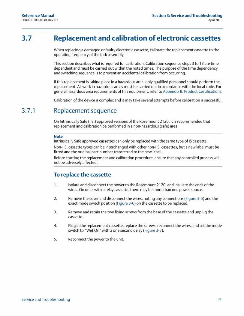
2. Remove the cover and disconnect the wires, noting any connections (Figure 3-5) and the exact mode switch position (Figure 3-6) on the cassette to be replaced.
3. Remove and retain the two fixing screws from the base of the cassette and unplug the cassette.
4. Plug in the replacement cassette, replace the screws, reconnect the wires, and set the mode switch to “Wet On” with a one second delay (Figure 3-7).
5. Reconnect the power to the unit.
33Service and Troubleshooting
Reference Manual00809-0100-4030, Rev ED
Section 3: Service and TroubleshootingApril 2015
34
Figure 3-5. Example of Installed Cassette
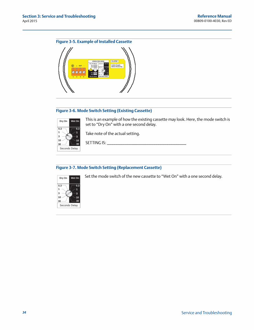
Figure 3-6. Mode Switch Setting (Existing Cassette)
This is an example of how the existing cassette may look. Here, the mode switch is set to “Dry On” with a one second delay.
Take note of the actual setting.
SETTING IS: ____________________________________
Figure 3-7. Mode Switch Setting (Replacement Cassette)
Set the mode switch of the new cassette to “Wet On” with a one second delay.
OPERATION MODE
Dry On ModeDryWet
Wet On Mode
DryWet
Dry On Wet On
Seconds Delay
0.3 0.3
3
3010
1
3
3010
1
1 2 3
OUT+ -
4
PLC/PNP
Isolate SupplyBefore Removing
Dry On Wet On
Seconds Delay
0.3 0.3
3
3010
1
3
3010
1
Dry On Wet On
Seconds Delay
0.3 0.3
3010
3
3010
131
Service and Troubleshooting
Reference Manual00809-0100-4030, Rev ED
Section 3: Service and TroubleshootingApril 2015
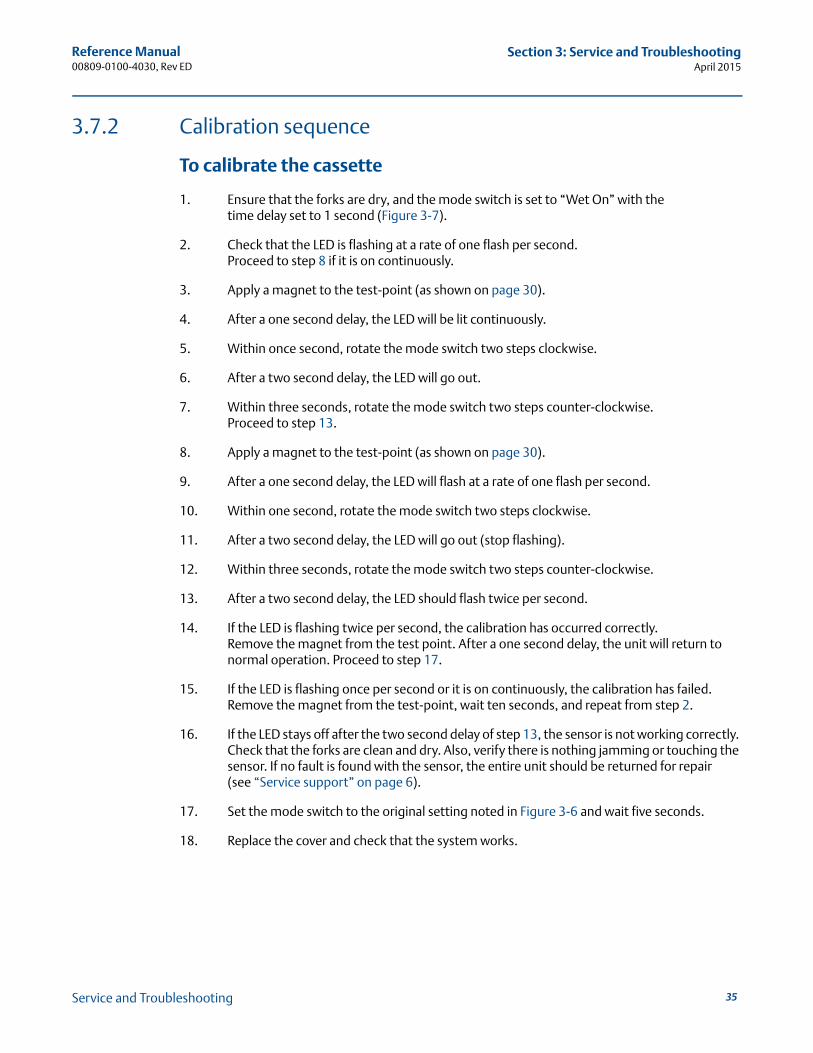
3.7.2 Calibration sequence
To calibrate the cassette
1. Ensure that the forks are dry, and the mode switch is set to “Wet On” with thetime delay set to 1 second (Figure 3-7).
2. Check that the LED is flashing at a rate of one flash per second.Proceed to step 8 if it is on continuously.
3. Apply a magnet to the test-point (as shown on page 30).
4. After a one second delay, the LED will be lit continuously.
5. Within once second, rotate the mode switch two steps clockwise.
6. After a two second delay, the LED will go out.
7. Within three seconds, rotate the mode switch two steps counter-clockwise. Proceed to step 13.
8. Apply a magnet to the test-point (as shown on page 30).
9. After a one second delay, the LED will flash at a rate of one flash per second.
10. Within one second, rotate the mode switch two steps clockwise.
11. After a two second delay, the LED will go out (stop flashing).
12. Within three seconds, rotate the mode switch two steps counter-clockwise.
13. After a two second delay, the LED should flash twice per second.
14. If the LED is flashing twice per second, the calibration has occurred correctly. Remove the magnet from the test point. After a one second delay, the unit will return to normal operation. Proceed to step 17.
15. If the LED is flashing once per second or it is on continuously, the calibration has failed. Remove the magnet from the test-point, wait ten seconds, and repeat from step 2.
16. If the LED stays off after the two second delay of step 13, the sensor is not working correctly. Check that the forks are clean and dry. Also, verify there is nothing jamming or touching the sensor. If no fault is found with the sensor, the entire unit should be returned for repair(see “Service support” on page 6).
17. Set the mode switch to the original setting noted in Figure 3-6 and wait five seconds.
18. Replace the cover and check that the system works.
35Service and Troubleshooting
Reference Manual00809-0100-4030, Rev ED
Section 3: Service and TroubleshootingApril 2015
36
Service and Troubleshooting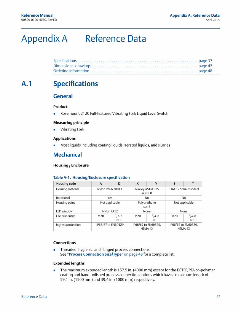
Reference Manual00809-0100-4030, Rev ED
Appendix A: Reference DataApril 2015
Appendix A Reference Data
Specifications . . . . . . . . . . . . . . . . . . . . . . . . . . . . . . . . . . . . . . . . . . . . . . . . . . . . . . . . . . . . . . . . page 37Dimensional drawings . . . . . . . . . . . . . . . . . . . . . . . . . . . . . . . . . . . . . . . . . . . . . . . . . . . . . . . . . page 42Ordering information . . . . . . . . . . . . . . . . . . . . . . . . . . . . . . . . . . . . . . . . . . . . . . . . . . . . . . . . . page 48
A.1 Specifications
General
Product
Rosemount 2120 Full-featured Vibrating Fork Liquid Level Switch
Measuring principle
Vibrating Fork
Applications
Most liquids including coating liquids, aerated liquids, and slurries
Mechanical
Housing / Enclosure
Table A-1. Housing/Enclosure specification
Connections
Threaded, hygienic, and flanged process connections.See “Process Connection Size/Type” on page 48 for a complete list.
Extended lengths
The maximum extended length is 157.5 in. (4000 mm) except for the ECTFE/PFA co-polymer coating and hand-polished process connection options which have a maximum length of 59.1 in. (1500 mm) and 39.4 in. (1000 mm) respectively.
Housing code A D X Y S T
Housing material Nylon PA66 30%GF Al alloy ASTM B85 A360.0
316C12 Stainless Steel
Rotational Yes No No
Housing paint Not applicable Polyurethanepaint
Not applicable
LED window Nylon PA12 None None
Conduit entry M20 1/2-in. NPT
M20 3/4-in. NPT
M20 3/4-in. NPT
Ingress protection IP66/67 to EN60529 IP66/67 to EN60529, NEMA 4X
IP66/67 to EN60529,NEMA 4X
37Reference Data
Reference Manual00809-0100-4030, Rev ED
Appendix A: Reference DataApril 2015
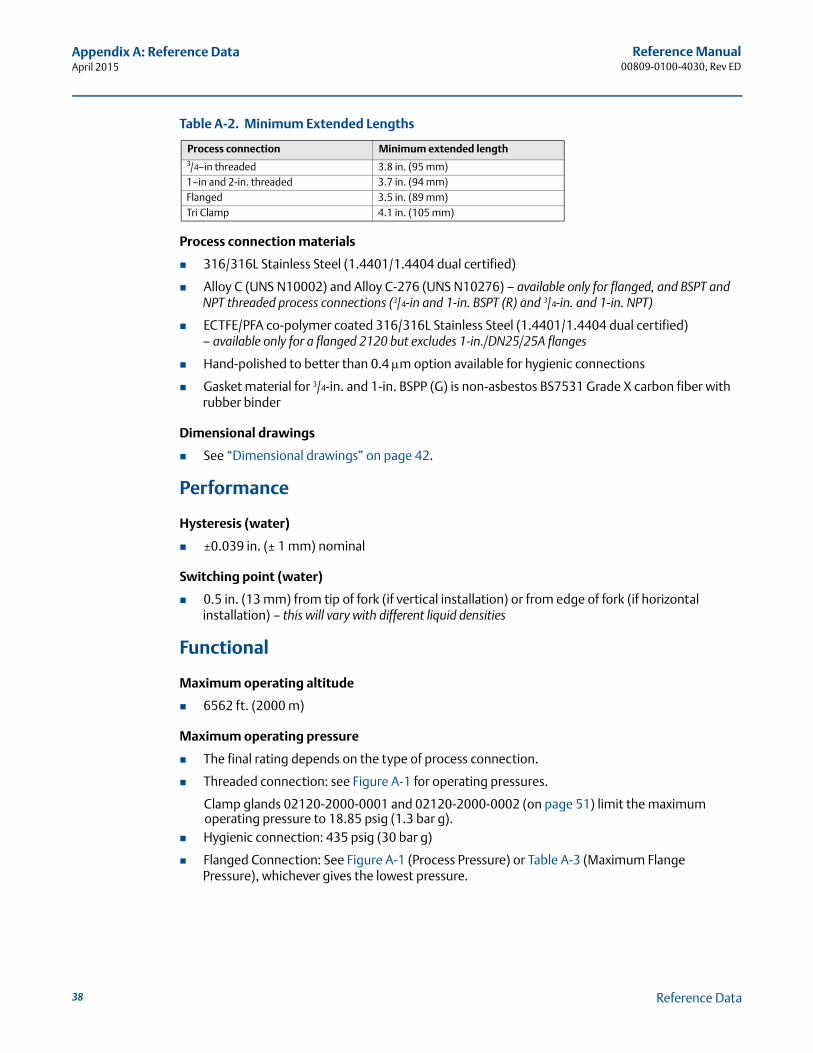
Table A-2. Minimum Extended Lengths
Process connection materials
316/316L Stainless Steel (1.4401/1.4404 dual certified)
Alloy C (UNS N10002) and Alloy C-276 (UNS N10276) – available only for flanged, and BSPT and NPT threaded process connections (3/4-in and 1-in. BSPT (R) and 3/4-in. and 1-in. NPT)
ECTFE/PFA co-polymer coated 316/316L Stainless Steel (1.4401/1.4404 dual certified)– available only for a flanged 2120 but excludes 1-in./DN25/25A flanges
Hand-polished to better than 0.4 m option available for hygienic connections
Gasket material for 3/4-in. and 1-in. BSPP (G) is non-asbestos BS7531 Grade X carbon fiber with rubber binder
Dimensional drawings
See “Dimensional drawings” on page 42.
Performance
Hysteresis (water)
±0.039 in. (± 1 mm) nominal
Switching point (water)
0.5 in. (13 mm) from tip of fork (if vertical installation) or from edge of fork (if horizontal installation) – this will vary with different liquid densities
Functional
Maximum operating altitude
6562 ft. (2000 m)
Maximum operating pressure
The final rating depends on the type of process connection.
Threaded connection: see Figure A-1 for operating pressures.
Clamp glands 02120-2000-0001 and 02120-2000-0002 (on page 51) limit the maximum operating pressure to 18.85 psig (1.3 bar g).
Hygienic connection: 435 psig (30 bar g)
Flanged Connection: See Figure A-1 (Process Pressure) or Table A-3 (Maximum Flange Pressure), whichever gives the lowest pressure.
Process connection Minimum extended length3/4–in threaded 3.8 in. (95 mm)1–in and 2-in. threaded 3.7 in. (94 mm)Flanged 3.5 in. (89 mm)Tri Clamp 4.1 in. (105 mm)
38 Reference Data
Reference Manual00809-0100-4030, Rev ED
Appendix A: Reference DataApril 2015
Figure A-1. Process Pressure
Table A-3. Maximum Flange Pressure Rating
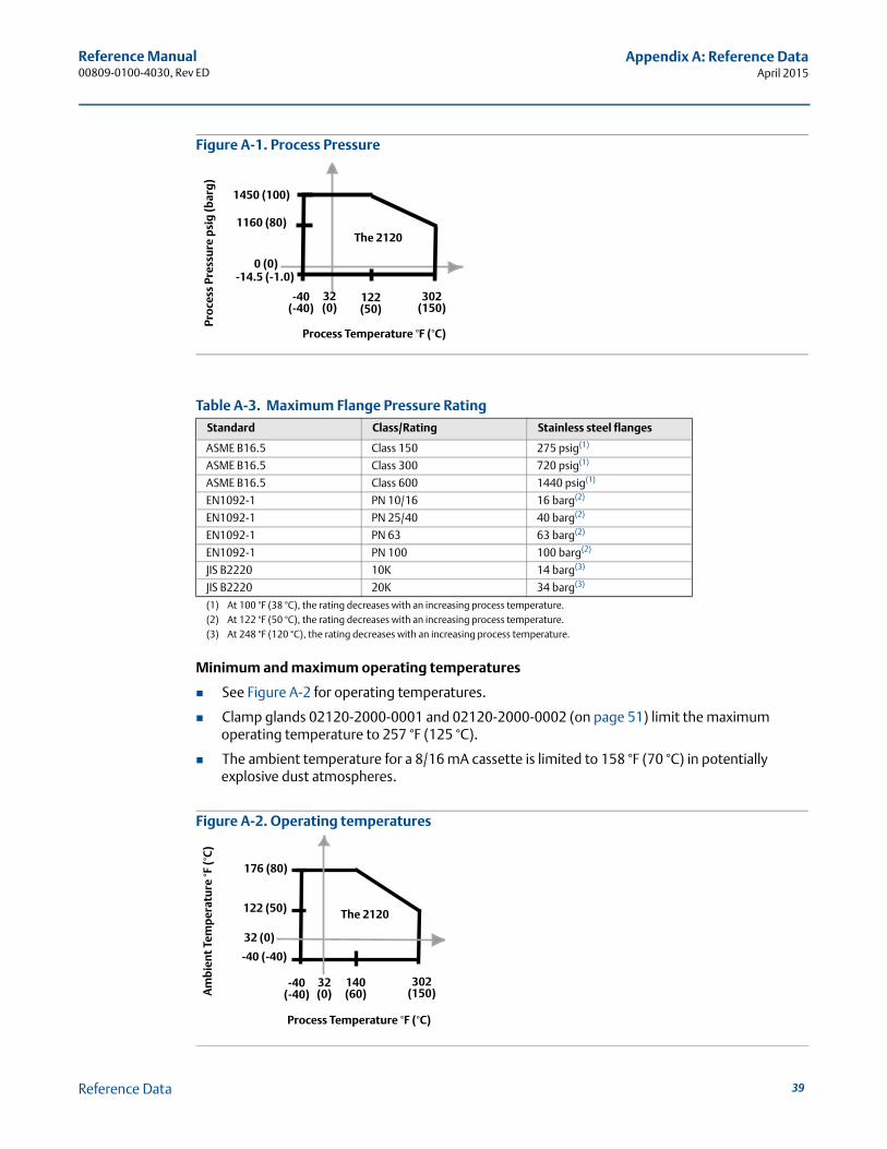
Minimum and maximum operating temperatures
See Figure A-2 for operating temperatures.
Clamp glands 02120-2000-0001 and 02120-2000-0002 (on page 51) limit the maximum operating temperature to 257 °F (125 °C).
The ambient temperature for a 8/16 mA cassette is limited to 158 °F (70 °C) in potentially explosive dust atmospheres.
Figure A-2. Operating temperatures
Standard Class/Rating Stainless steel flanges
ASME B16.5 Class 150 275 psig(1)
(1) At 100 °F (38 °C), the rating decreases with an increasing process temperature.
ASME B16.5 Class 300 720 psig(1)
ASME B16.5 Class 600 1440 psig(1)
EN1092-1 PN 10/16 16 barg(2)
EN1092-1 PN 25/40 40 barg(2)
EN1092-1 PN 63 63 barg(2)
(2) At 122 °F (50 °C), the rating decreases with an increasing process temperature.
EN1092-1 PN 100 100 barg(2)
JIS B2220 10K 14 barg(3)
(3) At 248 °F (120 °C), the rating decreases with an increasing process temperature.
JIS B2220 20K 34 barg(3)
1450 (100)
1160 (80)
-14.5 (-1.0)
-40 (-40)
122 (50)
302 (150)
Process Temperature °F (°C)
Pro
cess
Pre
ssu
re p
sig
(bar
g)
0 (0)
32 (0)
The 2120
176 (80)
140 (60)
-40 (-40)
-40 (-40)
302 (150)
Process Temperature °F (°C)
Am
bie
nt
Tem
per
atu
re °F
(°C
)
122 (50)
32 (0)
32 (0)
The 2120
39Reference Data
Reference Manual00809-0100-4030, Rev ED
Appendix A: Reference DataApril 2015
Liquid density requirement
Minimum is 37.5 lb/ft3 (600 kg/m3)
Liquid viscosity range
0.2 to 10000 cP (centiPoise)
Solids content and coating
The maximum recommended diameter of solid particles in the liquid is 0.2 in. (5 mm).
For a coating product, avoid bridging of forks.
Switching Delay
User-selectable 0.3, 1, 3, 10, 30 seconds delay for dry-to-wet and wet-to-dry switching
CIP (Clean In Place) and SIP (Steam In Place) cleaning
Withstands cleaning routines up to 275 °F (135 °C)
NACE
NACE compliance to MR0175 / ISO 15156 or MR0103, depending on the option code selected for the model number
Safety integrity level
The Rosemount 2120 FMEDA is certified for SIL2, and is SIL3 capable.
For more information, go to: http://www.emersonprocess.com/rosemount/safety/
Electrical
Switching mode
User-selectable switching mode (Dry = on or Wet = on)
Protection
Polarity insensitive – Relay (except 12 Vdc nominal version) and Direct Load electronics only
Over-current protection – Direct Load and PNP/PLC electronics only
Short-circuit protection – Direct Load and PNP/PLC electronics only
Load-missing protection – Direct Load and PNP/PLC electronics only
Surge protection (to IEC61326) – Available on all versions of the 2120
Heartbeat LED
The 2120 has a status-indicating heartbeat LED, which can be seen at all times and from all angles through a lens in the cover (no lens in metal housings).
The LED flashes when the output is ‘off’ and is constantly lit when it is ‘on’. The LED gives a constant indication that the 2120 is functioning correctly (different flash rates are used to indicate a product malfunction) and gives a local indication of the process state.
40 Reference Data
Reference Manual00809-0100-4030, Rev ED
Appendix A: Reference DataApril 2015
Magnetic test point
A magnetic test point is located on the side of the housing, allowing a functional test of the 2120 and a system connected to it. By holding a magnet to the target, the 2120 output changes state for as long as the magnet is held there.
Terminal connection (wire diameter)
Minimum 26 AWG, Maximum 14 AWG (0.13 to 2.5 mm2).Note national regulations.
Conduit plugs/cable gland
Metal housing: Conduit entries for explosion-proof areas are shipped with one Exd plug (loose in bag) and two dust caps fitted. Use suitably rated cable glands. Unused conduit entries must be sealed with a suitably rated blanking plug. Local codes and regulations must be complied with.
Glass-filled nylon housings with direct load, PNP/PLC and IS electronics are shipped with one PA66(1) cable gland and one blanking plug.
Glass-filled nylon housings with relay electronics are shipped with two PA66(1) cable glands.
Grounding
The 2120 should always be grounded, either through the terminals or using the external ground connection provided.
(1) Cable diameter 0.2 to 0.3 in. (5 to 8 mm)
41Reference Data
Reference Manual00809-0100-4030, Rev ED
Appendix A: Reference DataApril 2015
A.2 Dimensional drawings3/4 and 1-in. threaded mounting (standard length) . . . . . . . . . . . . . . . . . . . . . . . . . . . . . . . . page 423/4 and 1-in. thread mounting (extended length) . . . . . . . . . . . . . . . . . . . . . . . . . . . . . . . . . page 432-in. thread mounting . . . . . . . . . . . . . . . . . . . . . . . . . . . . . . . . . . . . . . . . . . . . . . . . . . . . . . . . . page 44Flange mounting (standard length) . . . . . . . . . . . . . . . . . . . . . . . . . . . . . . . . . . . . . . . . . . . . . page 45Flange mounting (extended length) . . . . . . . . . . . . . . . . . . . . . . . . . . . . . . . . . . . . . . . . . . . . . page 46Mobrey ‘A’ and ‘G’ flanges . . . . . . . . . . . . . . . . . . . . . . . . . . . . . . . . . . . . . . . . . . . . . . . . . . . . . page 47
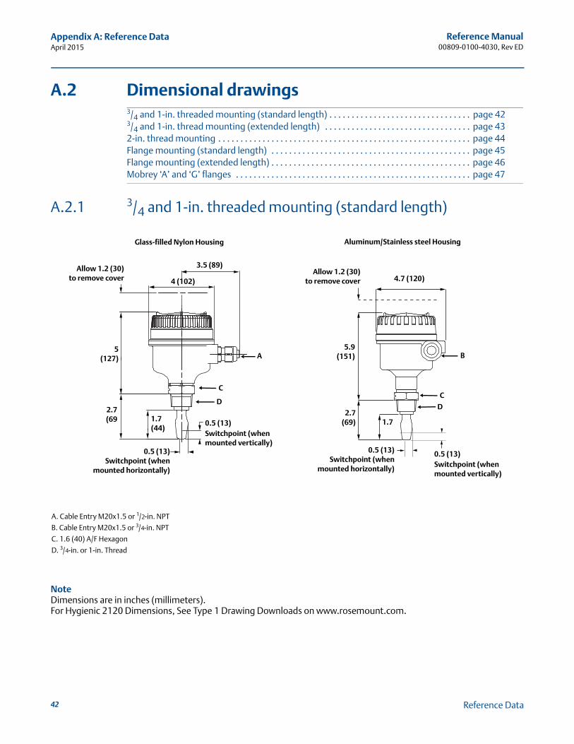
A.2.1 3/4 and 1-in. threaded mounting (standard length)
A. Cable Entry M20x1.5 or 1/2-in. NPT
B. Cable Entry M20x1.5 or 3/4-in. NPT
C. 1.6 (40) A/F Hexagon
D. 3/4-in. or 1-in. Thread
NoteDimensions are in inches (millimeters).For Hygienic 2120 Dimensions, See Type 1 Drawing Downloads on www.rosemount.com.
0.5 (13)Switchpoint (when
mounted horizontally)
0.5 (13)Switchpoint (when mounted vertically)
5(127)
3.5 (89)
1.7(44)
A
2.7(69
Allow 1.2 (30)to remove cover
Glass-filled Nylon Housing Aluminum/Stainless steel Housing
Allow 1.2 (30)to remove cover 4.7 (120)
5.9(151)
2.7(69) 1.7
0.5 (13)Switchpoint (when mounted vertically)
0.5 (13)Switchpoint (when
mounted horizontally)
B
C
D
C
D
4 (102)
42 Reference Data
Reference Manual00809-0100-4030, Rev ED
Appendix A: Reference DataApril 2015
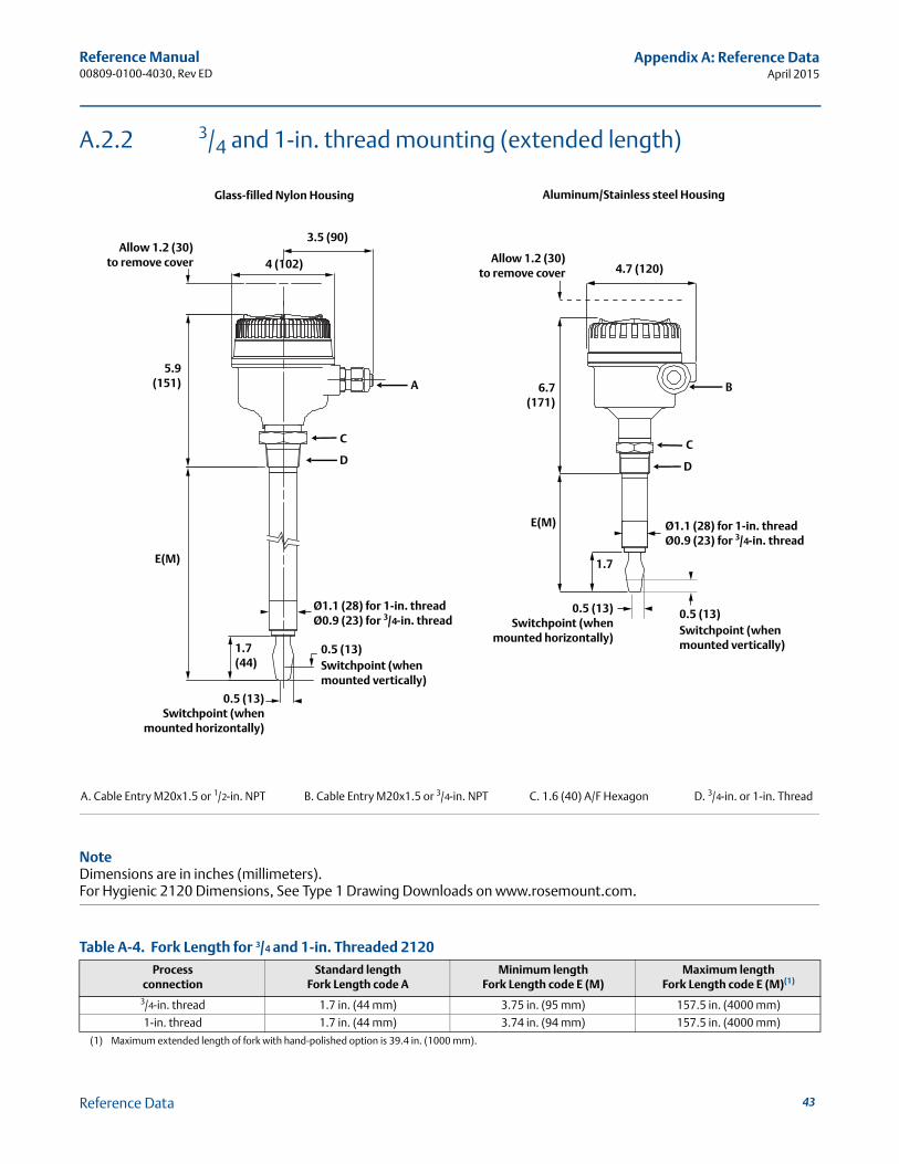
A.2.2 3/4 and 1-in. thread mounting (extended length)
A. Cable Entry M20x1.5 or 1/2-in. NPT B. Cable Entry M20x1.5 or 3/4-in. NPT C. 1.6 (40) A/F Hexagon D. 3/4-in. or 1-in. Thread
NoteDimensions are in inches (millimeters).For Hygienic 2120 Dimensions, See Type 1 Drawing Downloads on www.rosemount.com.
Table A-4. Fork Length for 3/4 and 1-in. Threaded 2120
Processconnection
Standard lengthFork Length code A
Minimum lengthFork Length code E (M)
Maximum length Fork Length code E (M)(1)
(1) Maximum extended length of fork with hand-polished option is 39.4 in. (1000 mm).
3/4-in. thread 1.7 in. (44 mm) 3.75 in. (95 mm) 157.5 in. (4000 mm)
1-in. thread 1.7 in. (44 mm) 3.74 in. (94 mm) 157.5 in. (4000 mm)
D
E(M)
1.7(44)
0.5 (13)Switchpoint (when
mounted horizontally)
0.5 (13)Switchpoint (when mounted vertically)
5.9(151)
Allow 1.2 (30)to remove cover
Ø1.1 (28) for 1-in. threadØ0.9 (23) for 3/4-in. thread
4.7 (120)
B
Allow 1.2 (30)to remove cover
6.7(171)
C
D
Ø1.1 (28) for 1-in. threadØ0.9 (23) for 3/4-in. thread
0.5 (13)Switchpoint (when mounted vertically)
0.5 (13)Switchpoint (when
mounted horizontally)
1.7E(M)
C
A
3.5 (90)
4 (102)
Glass-filled Nylon Housing Aluminum/Stainless steel Housing
43Reference Data
Reference Manual00809-0100-4030, Rev ED
Appendix A: Reference DataApril 2015
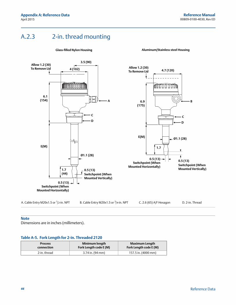
A.2.3 2-in. thread mounting
A. Cable Entry M20x1.5 or 1/2-in. NPT B. Cable Entry M20x1.5 or 3/4-in. NPT C. 2.6 (65) A/F Hexagon D. 2-in. Thread
NoteDimensions are in inches (millimeters).
Table A-5. Fork Length for 2-in. Threaded 2120
Processconnection
Minimum lengthFork Length code E (M)
Maximum Length Fork Length code E (M)
2-in. thread 3.74 in. (94 mm) 157.5 in. (4000 mm)
D
E(M)
1.7(44)
0.5 (13)Switchpoint (When
Mounted Horizontally)
0.5 (13)Switchpoint (When Mounted Vertically)
6.1(154)
Allow 1.2 (30)To Remove Lid
Ø1.1 (28)
4.7 (120)
B
Allow 1.2 (30)To Remove Lid
6.9(175)
C
D
Ø1.1 (28)
0.5 (13)Switchpoint (When Mounted Vertically)
0.5 (13)Switchpoint (When
Mounted Horizontally)
1.7E(M)
C
A
3.5 (90)
4 (102)
Glass-filled Nylon Housing Aluminum/Stainless steel Housing
44 Reference Data
Reference Manual00809-0100-4030, Rev ED
Appendix A: Reference DataApril 2015
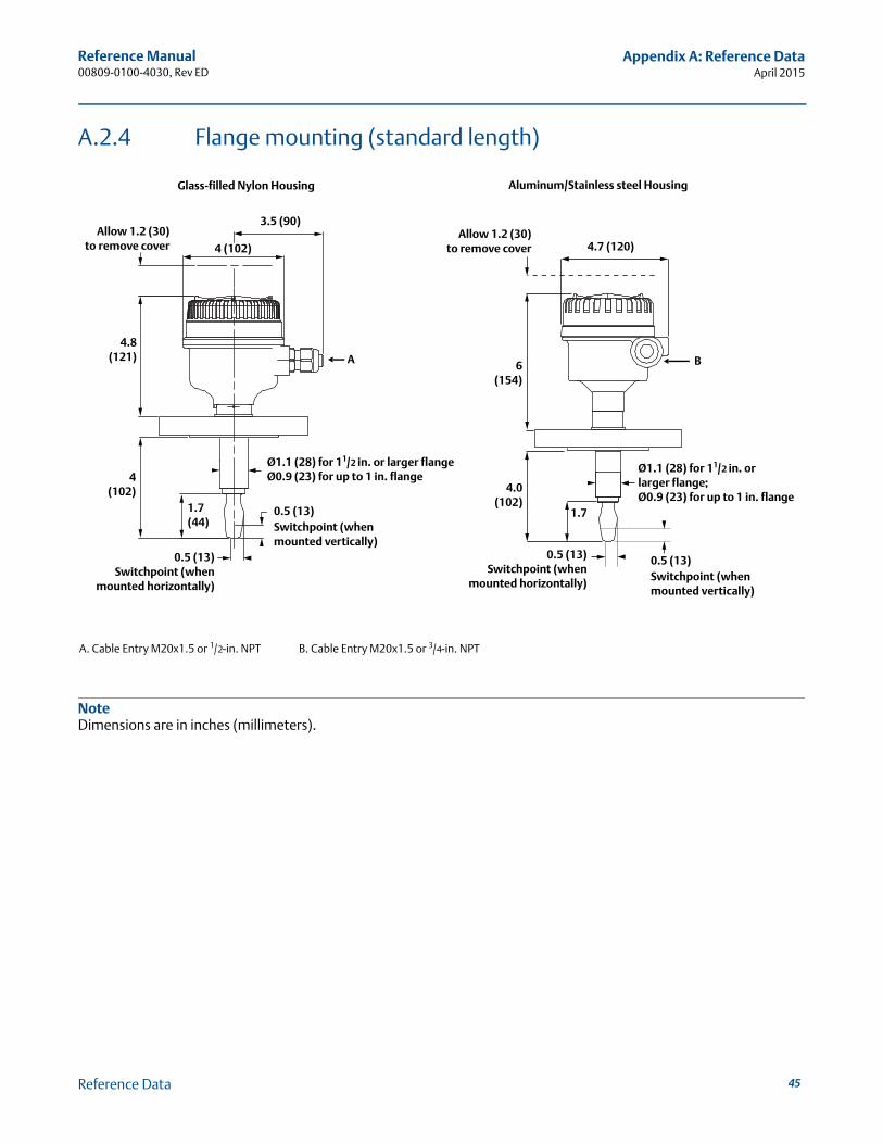
A.2.4 Flange mounting (standard length)
A. Cable Entry M20x1.5 or 1/2-in. NPT B. Cable Entry M20x1.5 or 3/4-in. NPT
NoteDimensions are in inches (millimeters).
4.8(121)
1.7(44)
0.5 (13)Switchpoint (when
mounted horizontally)
Ø1.1 (28) for 11/2 in. or larger flangeØ0.9 (23) for up to 1 in. flange
0.5 (13)Switchpoint (when mounted vertically)
Allow 1.2 (30)to remove cover 4.7 (120)
B
Allow 1.2 (30)to remove cover
6(154)
4.0(102)
1.7
0.5 (13)Switchpoint (when
mounted horizontally)
0.5 (13)Switchpoint (when mounted vertically)
Ø1.1 (28) for 11/2 in. orlarger flange;Ø0.9 (23) for up to 1 in. flange
A
3.5 (90)
4 (102)
4(102)
Glass-filled Nylon Housing Aluminum/Stainless steel Housing
45Reference Data
Reference Manual00809-0100-4030, Rev ED
Appendix A: Reference DataApril 2015
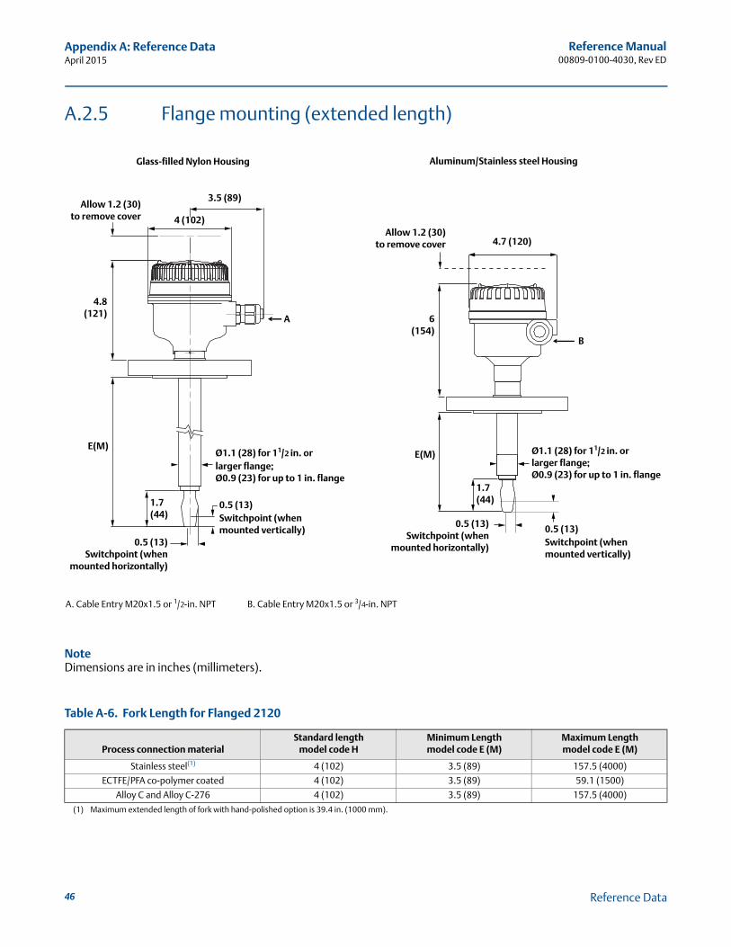
A.2.5 Flange mounting (extended length)
A. Cable Entry M20x1.5 or 1/2-in. NPT B. Cable Entry M20x1.5 or 3/4-in. NPT
NoteDimensions are in inches (millimeters).
Table A-6. Fork Length for Flanged 2120
Process connection materialStandard length
model code HMinimum Length model code E (M)
Maximum Lengthmodel code E (M)
Stainless steel(1)
(1) Maximum extended length of fork with hand-polished option is 39.4 in. (1000 mm).
4 (102) 3.5 (89) 157.5 (4000)
ECTFE/PFA co-polymer coated 4 (102) 3.5 (89) 59.1 (1500)
Alloy C and Alloy C-276 4 (102) 3.5 (89) 157.5 (4000)
1.7(44)
4.8(121)
E(M)
0.5 (13)Switchpoint (when
mounted horizontally)
Ø1.1 (28) for 11/2 in. orlarger flange;Ø0.9 (23) for up to 1 in. flange
0.5 (13)Switchpoint (when mounted vertically)
Allow 1.2 (30)to remove cover
4.7 (120)Allow 1.2 (30)
to remove cover
0.5 (13)Switchpoint (when
mounted horizontally)
0.5 (13)Switchpoint (when mounted vertically)
Ø1.1 (28) for 11/2 in. orlarger flange;Ø0.9 (23) for up to 1 in. flange
6(154)
E(M)
3.5 (89)
4 (102)
B
A
1.7(44)
Glass-filled Nylon Housing Aluminum/Stainless steel Housing
46 Reference Data
Reference Manual00809-0100-4030, Rev ED
Appendix A: Reference DataApril 2015
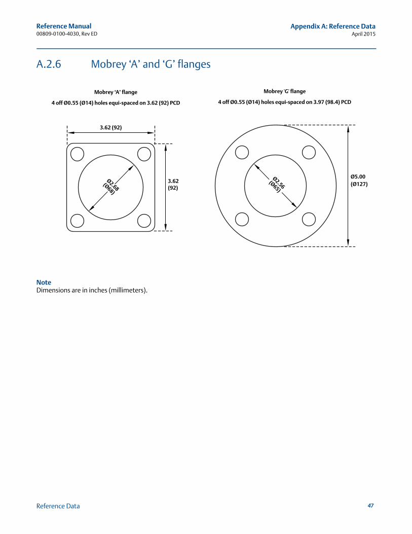
A.2.6 Mobrey ‘A’ and ‘G’ flanges
NoteDimensions are in inches (millimeters).
Mobrey ‘A’ flange
4 off Ø0.55 (Ø14) holes equi-spaced on 3.62 (92) PCD
Ø5.00(Ø127)
Ø2.56 (Ø65)
Ø2.68(Ø68)
Mobrey 'G' flange
4 off Ø0.55 (Ø14) holes equi-spaced on 3.97 (98.4) PCD
3.62 (92)
3.62 (92)
47Reference Data
Reference Manual00809-0100-4030, Rev ED
Appendix A: Reference DataApril 2015
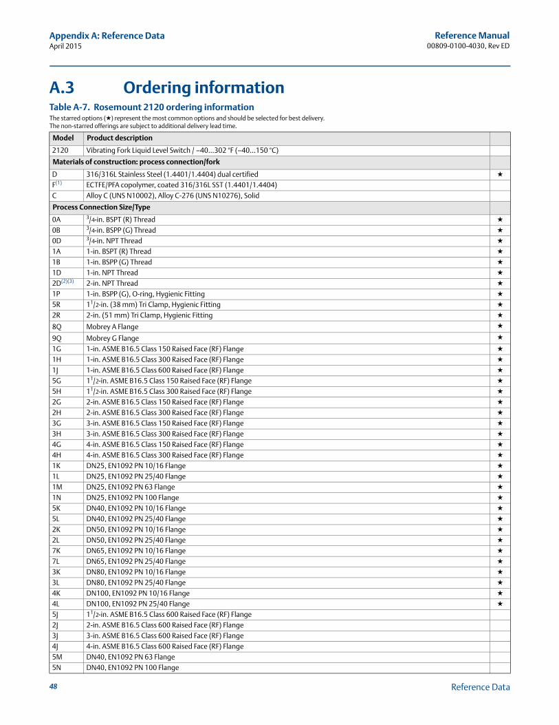
A.3 Ordering informationTable A-7. Rosemount 2120 ordering informationThe starred options (★) represent the most common options and should be selected for best delivery.The non-starred offerings are subject to additional delivery lead time.
Model Product description
2120 Vibrating Fork Liquid Level Switch / –40…302 °F (–40...150 °C)
Materials of construction: process connection/fork
D 316/316L Stainless Steel (1.4401/1.4404) dual certified ★
F(1) ECTFE/PFA copolymer, coated 316/316L SST (1.4401/1.4404)C Alloy C (UNS N10002), Alloy C-276 (UNS N10276), Solid
Process Connection Size/Type
0A 3/4-in. BSPT (R) Thread ★
0B 3/4-in. BSPP (G) Thread ★
0D 3/4-in. NPT Thread ★
1A 1-in. BSPT (R) Thread ★
1B 1-in. BSPP (G) Thread ★
1D 1-in. NPT Thread ★
2D(2)(3) 2-in. NPT Thread ★
1P 1-in. BSPP (G), O-ring, Hygienic Fitting ★
5R 11/2-in. (38 mm) Tri Clamp, Hygienic Fitting ★
2R 2-in. (51 mm) Tri Clamp, Hygienic Fitting ★
8Q Mobrey A Flange ★
9Q Mobrey G Flange ★
1G 1-in. ASME B16.5 Class 150 Raised Face (RF) Flange ★
1H 1-in. ASME B16.5 Class 300 Raised Face (RF) Flange ★
1J 1-in. ASME B16.5 Class 600 Raised Face (RF) Flange ★
5G 11/2-in. ASME B16.5 Class 150 Raised Face (RF) Flange ★
5H 11/2-in. ASME B16.5 Class 300 Raised Face (RF) Flange ★
2G 2-in. ASME B16.5 Class 150 Raised Face (RF) Flange ★
2H 2-in. ASME B16.5 Class 300 Raised Face (RF) Flange ★
3G 3-in. ASME B16.5 Class 150 Raised Face (RF) Flange ★
3H 3-in. ASME B16.5 Class 300 Raised Face (RF) Flange ★
4G 4-in. ASME B16.5 Class 150 Raised Face (RF) Flange ★
4H 4-in. ASME B16.5 Class 300 Raised Face (RF) Flange ★
1K DN25, EN1092 PN 10/16 Flange ★
1L DN25, EN1092 PN 25/40 Flange ★
1M DN25, EN1092 PN 63 Flange ★
1N DN25, EN1092 PN 100 Flange ★
5K DN40, EN1092 PN 10/16 Flange ★
5L DN40, EN1092 PN 25/40 Flange ★
2K DN50, EN1092 PN 10/16 Flange ★
2L DN50, EN1092 PN 25/40 Flange ★
7K DN65, EN1092 PN 10/16 Flange ★
7L DN65, EN1092 PN 25/40 Flange ★
3K DN80, EN1092 PN 10/16 Flange ★
3L DN80, EN1092 PN 25/40 Flange ★
4K DN100, EN1092 PN 10/16 Flange ★
4L DN100, EN1092 PN 25/40 Flange ★
5J 11/2-in. ASME B16.5 Class 600 Raised Face (RF) Flange2J 2-in. ASME B16.5 Class 600 Raised Face (RF) Flange3J 3-in. ASME B16.5 Class 600 Raised Face (RF) Flange4J 4-in. ASME B16.5 Class 600 Raised Face (RF) Flange5M DN40, EN1092 PN 63 Flange5N DN40, EN1092 PN 100 Flange
48 Reference Data
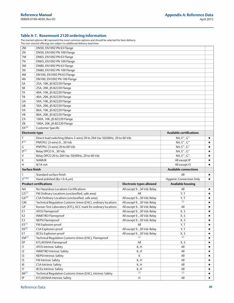
Reference Manual00809-0100-4030, Rev ED
Appendix A: Reference DataApril 2015
2M DN50, EN1092 PN 63 Flange2N DN50, EN1092 PN 100 Flange7M DN65, EN1092 PN 63 Flange7N DN65, EN1092 PN 100 Flange3M DN80, EN1092 PN 63 Flange3N DN80, EN1092 PN 100 Flange4M DN100, EN1092 PN 63 Flange4N DN100, EN1092 PN 100 FlangeSA 25A, 10K, JIS B2220 FlangeSB 25A, 20K, JIS B2220 FlangeTA 40A, 10K, JIS B2220 FlangeTB 40A, 20K, JIS B2220 FlangeUA 50A, 10K, JIS B2220 FlangeUB 50A, 20K, JIS B2220 FlangeVA 80A, 10K, JIS B2220 FlangeVB 80A, 20K, JIS B2220 FlangeZA 100A, 10K, JIS B2220 FlangeZB 100A, 20K, JIS B2220 FlangeXX(4) Customer Specific
Electronic type Available certifications
T Direct load switching (Mains 2-wire) 20 to 264 Vac 50/60Hz, 20 to 60 Vdc NA, E*, G* ★
F(2) PNP/PLC (3-wire) 9...30 Vdc NA, E*, G* ★
G PNP/PLC (3-wire) 20 to 60 Vdc NA, E*, G* ★
D(2) Relay DPCO 9...30 Vdc NA, E*, G* ★
V Relay DPCO 20 to 264 Vac 50/60Hz, 20 to 60 Vdc NA, E*, G* ★
K NAMUR All except IP ★
H 8/16 mA All except I3 ★
Surface finish Available connections
1 Standard surface finish All ★
2(5)(6) Hand polished (Ra < 0.4 μm) Hygienic Connection Only ★
Product certifications Electronic types allowed Available housing
NA No Hazardous Locations Certifications All except 9...30 Vdc Relay All ★
G5(7) FM Ordinary Locations (unclassified, safe area) All Y, T ★
G6(8) CSA Ordinary Locations (unclassified, safe area) All except 9...30 Vdc Relay Y, T ★
GM Technical Regulation Customs Union (EAC), ordinary locations All except 9...30 Vdc Relay (2) ★
GP Korean Test Laboratory (KTL), KCC mark for ordinary locations All except 9...30 Vdc Relay All ★
E1 ATEX Flameproof All except 9...30 Vdc Relay X, S ★
E2 INMETRO Flameproof All except 9...30 Vdc Relay X, S ★
E3 NEPSI Flameproof All except 9...30 Vdc Relay X, S ★
E5(7) FM Explosion-proof All Y, T ★
E6(8) CSA Explosion-proof All except 9...30 Vdc Relay Y, T ★
E7 IECEx Explosion-proof All except 9...30 Vdc Relay X, S ★
EM(2) Technical Regulation Customs Union (EAC), Flameproof (2) (2) ★
EP KTL/KOSHA Flameproof All X, S ★
I1 ATEX Intrinsic Safety K, H All ★
I2 INMETRO Intrinsic Safety K, H All ★
I3 NEPSI Intrinsic Safety K All ★
I5 FM Intrinsic Safety K, H All ★
I6 CSA Intrinsic Safety K, H All ★
I7 IECEx Intrinsic Safety K, H All ★
IM(2) Technical Regulation Customs Union (EAC), Intrinsic Safety (2) (2) ★
IP KTL/KOSHA Intrinsic Safety H All ★
Table A-7. Rosemount 2120 ordering informationThe starred options (★) represent the most common options and should be selected for best delivery.The non-starred offerings are subject to additional delivery lead time.
49Reference Data
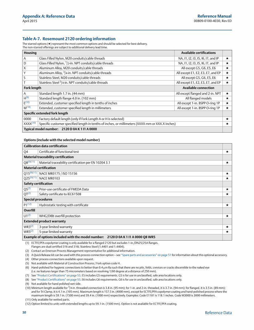
Reference Manual00809-0100-4030, Rev ED
Appendix A: Reference DataApril 2015
Housing Available certifications
A Glass Filled Nylon, M20 conduits/cable threads NA, I1, I2, I3, I5, I6, I7, and IP ★
D Glass Filled Nylon, 1/2-in. NPT conduits/cable threads NA, I1, I2, I3, I5, I6, I7, and IP ★
X Aluminum Alloy, M20 conduits/cable threads All except G5, G6, E5, E6 ★
Y Aluminum Alloy, 3/4-in. NPT conduits/cable threads All except E1, E2, E3, E7, and EP ★
S Stainless Steel, M20 conduits/cable threads All except G5, G6, E5, E6 ★
T Stainless Steel 3/4-in. NPT conduits/cable threads All except E1, E2, E3, E7, and EP ★
Fork length Available connection
A Standard length 1.7 in. (44 mm) All except flanged and 2-in. NPT ★
H(9) Standard length flange 4.0 in. (102 mm) All flanged models ★
E(10) Extended, customer specified length in tenths of inches All except 1-in. BSPP O-ring 1P ★
M(10) Extended, customer specified length in millimeters All except 1-in. BSPP O-ring 1P ★
Specific extended fork length
0000 Factory default length (only if Fork Length A or H is selected) ★
XXXX(10) Specific customer specified length in tenths of inches, or millimeters (XXXX mm or XXX.X inches) ★
Typical model number: 2120 D 0A K 1 I1 A 0000
Options (include with the selected model number)
Calibration data certification
Q4 Certificate of functional test ★
Material traceability certification
Q8(9)(11) Material traceability certification per EN 10204 3.1 ★
Material certification
Q15(9)(11) NACE MR0175 / ISO 15156 ★
Q25(9)(11) NACE MR0103 ★
Safety certification
QS(2) Prior-use certificate of FMEDA Data ★
QT(2) Safety certificate to IEC61508 ★
Special procedures
P1(12) Hydrostatic testing with certificate ★
Overfill
U1(2) WHG/DIBt overfill protection ★
Extended product warranty
WR3(2) 3-year limited warranty ★
WR5(2) 5-year limited warranty ★
Example of options included with the model number: 2120 D 0A K 1 I1 A 0000 Q8 WR5
(1) ECTFE/PFA copolymer coating is only available for a flanged 2120 but excludes 1-in./DN25/25A flanges.Flanges are dual certified 316 and 316L Stainless Steel (1.4401 and 1.4404).
(2) Contact an Emerson Process Management representative for additional information.(3) A Quick Release kit can be used with this process connection option – see “Spare parts and accessories” on page 51 for information about this optional accessory.(4) Other process connections available upon request.(5) Not available with Material of Construction Process / Fork option code H.(6) Hand-polished for hygienic connections to better than 0.4 m Ra such that there are no pits, folds, crevices or cracks discernible to the naked eye
(i.e. no features larger than 75 micrometers based on resolving 1/60 degree at a distance of 250 mm).(7) See ”Product Certifications” on page 53. E5 includes G5 requirements. G5 is for use in unclassified, safe area locations only.(8) See ”Product Certifications” on page 53. E6 includes G6 requirements. G6 is for use in unclassified, safe area locations only.(9) Not available for hand polished wet side.(10) Minimum length available for 3/4-in. threaded connection is 3.8 in. (95 mm); for 1-in. and 2-in. threaded, it is 3.7 in. (94 mm); for flanged, it is 3.5 in. (89 mm);
and for Tri Clamp, it is 4.1 in. (105 mm). Maximum length is 157.5 in. (4000 mm), except for ECTFE/PFA copolymer coating and hand-polished process where the maximum length is 59.1 in. (1500 mm) and 39.4 in. (1000 mm) respectively. Examples: Code E1181 is 118.1 inches. Code M3000 is 3000 millimeters.
(11) Only available for wetted parts.(12) Option limited to units with extended lengths up to 59.1-in. (1500 mm). Option is not available for ECTFE/PFA coating.
Table A-7. Rosemount 2120 ordering informationThe starred options (★) represent the most common options and should be selected for best delivery.The non-starred offerings are subject to additional delivery lead time.
50 Reference Data
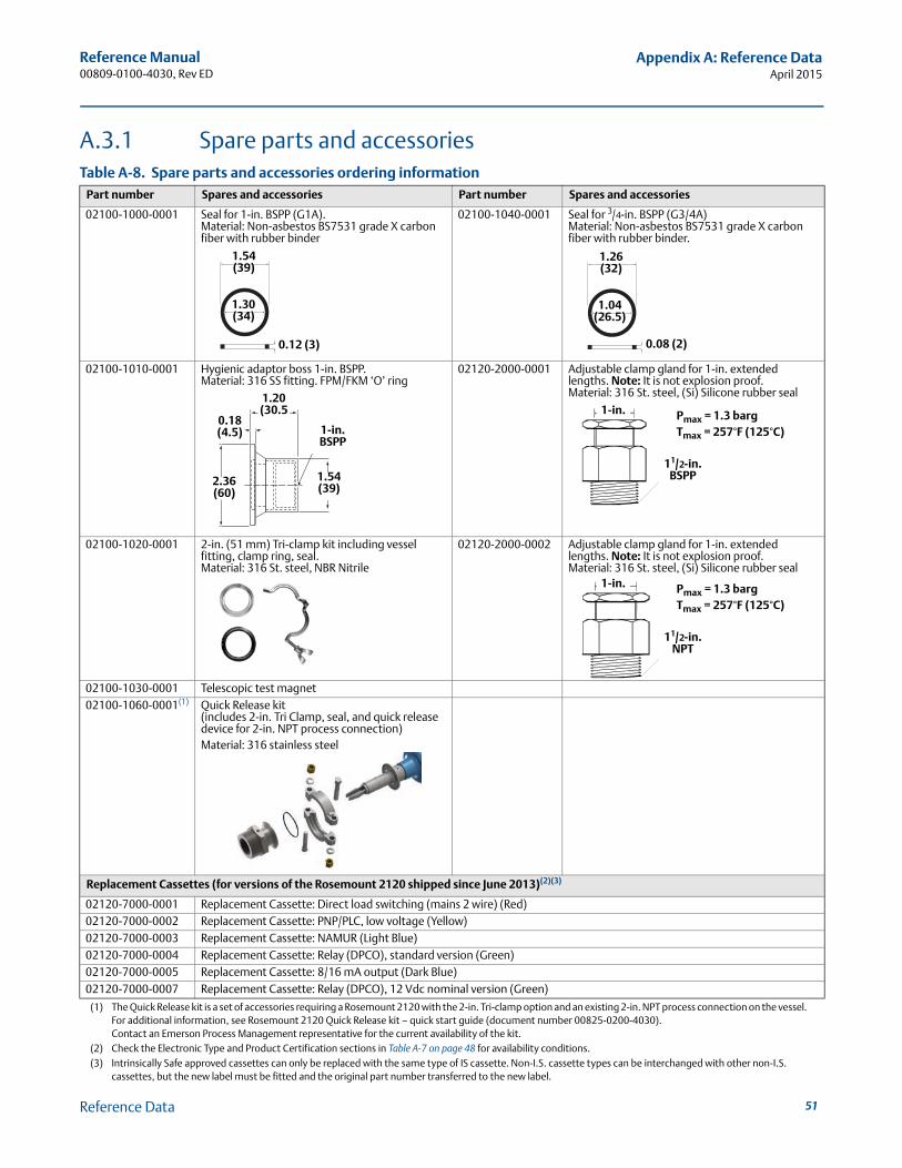
Reference Manual00809-0100-4030, Rev ED
Appendix A: Reference DataApril 2015
A.3.1 Spare parts and accessoriesTable A-8. Spare parts and accessories ordering information
Part number Spares and accessories Part number Spares and accessories
02100-1000-0001 Seal for 1-in. BSPP (G1A). Material: Non-asbestos BS7531 grade X carbon fiber with rubber binder
02100-1040-0001 Seal for 3/4-in. BSPP (G3/4A)Material: Non-asbestos BS7531 grade X carbon fiber with rubber binder.
02100-1010-0001 Hygienic adaptor boss 1-in. BSPP. Material: 316 SS fitting. FPM/FKM ‘O’ ring
02120-2000-0001 Adjustable clamp gland for 1-in. extended lengths. Note: It is not explosion proof.Material: 316 St. steel, (Si) Silicone rubber seal
02100-1020-0001 2-in. (51 mm) Tri-clamp kit including vessel fitting, clamp ring, seal. Material: 316 St. steel, NBR Nitrile
02120-2000-0002 Adjustable clamp gland for 1-in. extended lengths. Note: It is not explosion proof.Material: 316 St. steel, (Si) Silicone rubber seal
02100-1030-0001 Telescopic test magnet02100-1060-0001(1)
(1) The Quick Release kit is a set of accessories requiring a Rosemount 2120 with the 2-in. Tri-clamp option and an existing 2-in. NPT process connection on the vessel. For additional information, see Rosemount 2120 Quick Release kit – quick start guide (document number 00825-0200-4030).Contact an Emerson Process Management representative for the current availability of the kit.
Quick Release kit (includes 2-in. Tri Clamp, seal, and quick release device for 2-in. NPT process connection)Material: 316 stainless steel
Replacement Cassettes (for versions of the Rosemount 2120 shipped since June 2013)(2)(3)
(2) Check the Electronic Type and Product Certification sections in Table A-7 on page 48 for availability conditions.(3) Intrinsically Safe approved cassettes can only be replaced with the same type of IS cassette. Non-I.S. cassette types can be interchanged with other non-I.S.
cassettes, but the new label must be fitted and the original part number transferred to the new label.
02120-7000-0001 Replacement Cassette: Direct load switching (mains 2 wire) (Red)02120-7000-0002 Replacement Cassette: PNP/PLC, low voltage (Yellow)02120-7000-0003 Replacement Cassette: NAMUR (Light Blue)02120-7000-0004 Replacement Cassette: Relay (DPCO), standard version (Green)02120-7000-0005 Replacement Cassette: 8/16 mA output (Dark Blue)02120-7000-0007 Replacement Cassette: Relay (DPCO), 12 Vdc nominal version (Green)
1.54 (39)
1.30 (34)
0.12 (3)
1.26 (32)
1.04 (26.5)
0.08 (2)
1.20 (30.5
1-in. BSPP
2.36 (60)
0.18 (4.5)
1.54 (39)
1-in.
11/2-in. BSPP
Pmax = 1.3 bargTmax = 257°F (125°C)
1-in.
11/2-in. NPT
Pmax = 1.3 bargTmax = 257°F (125°C)
51Reference Data
Reference Manual00809-0100-4030, Rev ED
Appendix A: Reference DataApril 2015
52 Reference Data
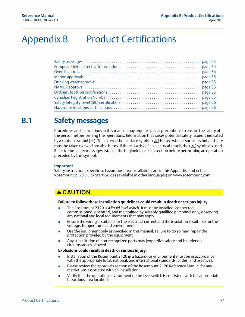
Reference Manual00809-0100-4030, Rev ED
Appendix B: Product CertificationsApril 2015
Appendix B Product Certifications
Safety messages . . . . . . . . . . . . . . . . . . . . . . . . . . . . . . . . . . . . . . . . . . . . . . . . . . . . . . . . . . . . . . page 53European Union directive information . . . . . . . . . . . . . . . . . . . . . . . . . . . . . . . . . . . . . . . . . . . page 54Overfill approval . . . . . . . . . . . . . . . . . . . . . . . . . . . . . . . . . . . . . . . . . . . . . . . . . . . . . . . . . . . . . . page 54Marine approvals . . . . . . . . . . . . . . . . . . . . . . . . . . . . . . . . . . . . . . . . . . . . . . . . . . . . . . . . . . . . . page 55Drinking water approval . . . . . . . . . . . . . . . . . . . . . . . . . . . . . . . . . . . . . . . . . . . . . . . . . . . . . . . page 55NAMUR approval . . . . . . . . . . . . . . . . . . . . . . . . . . . . . . . . . . . . . . . . . . . . . . . . . . . . . . . . . . . . . page 55Ordinary location certifications . . . . . . . . . . . . . . . . . . . . . . . . . . . . . . . . . . . . . . . . . . . . . . . . . page 55Canadian Registration Number . . . . . . . . . . . . . . . . . . . . . . . . . . . . . . . . . . . . . . . . . . . . . . . . . page 55Safety Integrity Level (SIL) certification . . . . . . . . . . . . . . . . . . . . . . . . . . . . . . . . . . . . . . . . . . page 56Hazardous locations certifications . . . . . . . . . . . . . . . . . . . . . . . . . . . . . . . . . . . . . . . . . . . . . . page 56
B.1 Safety messagesProcedures and instructions in this manual may require special precautions to ensure the safety of the personnel performing the operations. Information that raises potential safety issues is indicated by a caution symbol ( ). The external hot surface symbol ( ) is used when a surface is hot and care must be taken to avoid possible burns. If there is a risk of an electrical shock, the ( ) symbol is used. Refer to the safety messages listed at the beginning of each section before performing an operation preceded by this symbol.
ImportantSafety instructions specific to hazardous area installations are in this Appendix, and in the Rosemount 2120 Quick Start Guides (available in other languages) on www.rosemount.com.
Failure to follow these installation guidelines could result in death or serious injury.
The Rosemount 2120 is a liquid level switch. It must be installed, connected, commissioned, operated, and maintained by suitably qualified personnel only, observing any national and local requirements that may apply
Ensure the wiring is suitable for the electrical current and the insulation is suitable for the voltage, temperature, and environment
Use the equipment only as specified in this manual. Failure to do so may impair the protection provided by the equipment
Any substitution of non-recognized parts may jeopardize safety and is under no circumstances allowed
Explosions could result in death or serious injury.
Installation of the Rosemount 2120 in a hazardous environment must be in accordance with the appropriate local, national, and international standards, codes, and practices.
Please review the approvals section of the Rosemount 2120 Reference Manual for any restrictions associated with an installation
Verify that the operating environment of the level switch is consistent with the appropriate hazardous area locations
53Product Certifications
Reference Manual00809-0100-4030, Rev ED
Appendix B: Product CertificationsApril 2015
54
B.2 European Union directive informationThe EC declaration of conformity for all applicable European directives for this product can be found on the Rosemount website at www.rosemount.com. A hard copy may be obtained by contacting your local sales office.
ATEX directive Complies with the ATEX Directive.
Pressure equipment directive (PED) The Rosemount 2120 is outside the scope of PED directive.
Low voltage directive (LVD) EN61010-1 Pollution degree 2, Category II (264V max),
Pollution degree 2, Category III (150V max).
Electro magnetic compatibility (EMC) directive EN61326 Emissions to Class B.
Immunity to industrial location requirements.
NAMUR NE21.
CE-mark Complies with applicable directives (EMC, ATEX, LVD).
B.3 Overfill approval Certificate number: Z-65.11-522. TÜV-tested and approved for overfill protection according to
the German DIBt/WHG regulations. Certified under safety devices for tanks and piping related to water pollution control.
External Surface may be hot.
Care must be taken to avoid possible burnsProcess leaks could result in death or serious injury.
Install and tighten process connectors before applying pressure Do not attempt to loosen or remove process connectors while the Rosemount 2120 is in
serviceElectrical shock could cause death or serious injury.
If the liquid level switch is installed in a high voltage environment and a fault condition or installation error occurs, high voltage may be present on leads and terminals
Use extreme caution when making contact with the leads and terminals Make sure that power to the Rosemount 2120 is off while making connections
Product Certifications
Reference Manual00809-0100-4030, Rev ED
Appendix B: Product CertificationsApril 2015
B.4 Marine approvals ABS – American Bureau of Shipping
GL – Germanischer Lloyd
SRS – Russian Maritime Registered Shipping (RMRS)
B.5 Drinking water approvalRosemount Measurement Ltd. (United Kingdom) confirms that the wetted parts of the Rosemount 2120 vibrating fork level switch are suitable and approved for drinking water usage. The wetted parts of the vibrating fork level switches executed in stainless steel (option code D) and Alloy C / Alloy C-276 (option code C) with flanged, NPT thread, BSPT(R) thread, or Tri-clamp process connections, are in accordance with the requirements of DVGW*- Worksheet W270.The materials used are classified as toxicologically and microbiologically safe.
B.6 NAMUR approvalNAMUR NE95 type test is available upon request. Complies with NAMUR NE21.
B.7 Ordinary location certifications
FM ordinary location certification
G5 Project ID: 3021776
The switch has been examined and tested to determine that the design meets basic electrical, mechanical, and fire protection requirements by FM, a nationally recognized testing laboratory (NRTL) as accredited by the Federal Occupational Safety and Health Administration (OSHA)
CSA ordinary location certification
G6 Certificate Number 06 CSA 1805769
The switch has been examined and tested to determine that the design meets basic electrical, mechanical, and fire protection requirements by CSA, a nationally recognized testing laboratory as accredited by the Standards Council of Canada (SCC). Single seal.
Technical Regulation Customs Union (EAC), ordinary locations mark
GM Contact an Emerson Process Management representative for additional information.
Korean Testing Laboratory (KTL), KCC mark for ordinary locations use
GP EMC Certificate: KCC-REM-ERN-RMDSWIT2120XXX
B.8 Canadian Registration Number
Certificate Number CRN 0F04227.2C
The requirements of CRN are met when a Rosemount 2120 CSA IS-approved (G6, E6, or I6 option codes) vibrating fork level switch model is configured with 316/316L stainless steel (1.4401/1.4404) wetted parts and either NPT threaded or 2 to 8-in. ASME B16.5 flanged process connections.
55Product Certifications
Reference Manual00809-0100-4030, Rev ED
Appendix B: Product CertificationsApril 2015
56
B.9 Safety Integrity Level (SIL) certificationThe Rosemount 2120 has been independently certified to IEC 61508 as required by IEC 61511. Certification was conducted by Exida. The Rosemount 2120 is SIL2-certified and SIL3-capable.
B.10 Hazardous locations certifications
B.10.1 American and Canadian approvals
Factory Mutual (FM) explosion-proof approvalE5 Project ID: 3012658
Explosion-proof for Class I, Div. 1, Groups A, B, C, and DTemperature Class: T6Enclosure: Type 4X(See also "Instructions for hazardous area installations (E5 and E6)" ).
Canadian Standards Association (CSA) explosion-proof approvalE6 Project ID: 1786345
Explosion-proof for Class I, Div. 1, Groups A, B, C, and DTemperature Class: T6Enclosure: Type 4XSingle seal(See also "Instructions for hazardous area installations (E5 and E6)" ).
Instructions for hazardous area installations (E5 and E6)Model numbers covered: 2120*****E5Y**, 2120*****E5T**, 2120*****E6Y**, 2120*****E6T**(“*” indicates options in construction, function and materials – see Table A-7 on page A-48).
The following instructions apply to equipment covered by CSA and FM explosion-proof approvals:
1. The equipment may be used with flammable gases and vapors with apparatusClass 1, Div 1, Groups A, B, C and D.
2. CSA and FM explosion-proof approved versions of the 2120 are certified for use in ambient temperatures of –40 °F to 176 °F (–40 °C to 80 °C), and with a maximum process temperature of 302 °F (150 °C).
3. Installation of this equipment shall be carried out by suitably trained personnel, in accordance with the applicable code of practice.
4. Inspection and maintenance of this equipment shall be carried out by suitably trained personnel, in accordance with the applicable code of practice.
5. The user should not repair this equipment.
6. The certification of this equipment relies upon the following materials used in its construction:
Body: Aluminum Alloy (ASTM B85 360.0) or 316 Stainless SteelCover: Aluminum Alloy (ASTM B85 360.0) or 316 Stainless SteelProbe: 316 Stainless Steel, or Alloy C276 (UNS N10276) and Alloy C (UNS N10002)Probe Filling: Perlite; Cover Seal: Silicone
Product Certifications
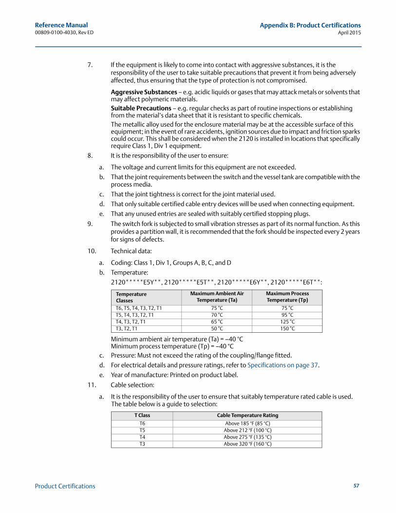
Reference Manual00809-0100-4030, Rev ED
Appendix B: Product CertificationsApril 2015
7. If the equipment is likely to come into contact with aggressive substances, it is the responsibility of the user to take suitable precautions that prevent it from being adversely affected, thus ensuring that the type of protection is not compromised.
Aggressive Substances – e.g. acidic liquids or gases that may attack metals or solvents that may affect polymeric materials. Suitable Precautions – e.g. regular checks as part of routine inspections or establishing from the material’s data sheet that it is resistant to specific chemicals.The metallic alloy used for the enclosure material may be at the accessible surface of this equipment; in the event of rare accidents, ignition sources due to impact and friction sparks could occur. This shall be considered when the 2120 is installed in locations that specifically require Class 1, Div 1 equipment.
8. It is the responsibility of the user to ensure:
a. The voltage and current limits for this equipment are not exceeded.
b. That the joint requirements between the switch and the vessel tank are compatible with the process media.
c. That the joint tightness is correct for the joint material used.
d. That only suitable certified cable entry devices will be used when connecting equipment.
e. That any unused entries are sealed with suitably certified stopping plugs.
9. The switch fork is subjected to small vibration stresses as part of its normal function. As this provides a partition wall, it is recommended that the fork should be inspected every 2 years for signs of defects.
10. Technical data:
a. Coding: Class 1, Div 1, Groups A, B, C, and D
b. Temperature:
2120*****E5Y**, 2120*****E5T**, 2120*****E6Y**, 2120*****E6T**:
Minimum ambient air temperature (Ta) = –40 °CMinimum process temperature (Tp) = –40 °C
c. Pressure: Must not exceed the rating of the coupling/flange fitted.
d. For electrical details and pressure ratings, refer to Specifications on page 37.
e. Year of manufacture: Printed on product label.
11. Cable selection:
a. It is the responsibility of the user to ensure that suitably temperature rated cable is used. The table below is a guide to selection:
Temperature Classes
Maximum Ambient Air Temperature (Ta)
Maximum Process Temperature (Tp)
T6, T5, T4, T3, T2, T1 75 °C 75 °CT5, T4, T3, T2, T1 70 °C 95 °CT4, T3, T2, T1 65 °C 125 °CT3, T2, T1 50 °C 150 °C
T Class Cable Temperature Rating
T6 Above 185 °F (85 °C)T5 Above 212 °F (100 °C)T4 Above 275 °F (135 °C)T3 Above 320 °F (160 °C)
57Product Certifications
Reference Manual00809-0100-4030, Rev ED
Appendix B: Product CertificationsApril 2015
58
NoteA certified isolating amplifier to IEC 60947-5-6 is required for intrinsic safety if the NAMUR electronics is used in a hazardous area installation (see below).
A certified intrinsically safe barrier is required for intrinsic safety if the 8/16 mA electronics is used in a hazardous area installation (see below).
Factory Mutual (FM)intrinsically safe and non-incendive approvalsI5 Project ID: 3011456
Intrinsically Safe for Class I, Div. 1, Groups A, B, C, and DClass I, Zone 0, AEx ia IICNon-incendive for Class I, Div. 2, Groups A, B, C, and DClass I, Zone 2, IICTemperature Code: T5 (See Control Drawings)
Control Drawing: 71097/1154 (with NAMUR electronics) (Figure B-1 on page 61)Vmax=15 V, Imax=32 mA, Pi=0.1 W, Ci=211 nF, Li=0.06 mH
Control Drawing: 71097/1314 (with 8/16 mA electronics) (Figure B-2 on page 62)Vmax=30 V, Imax=93 mA, Pi=0.65 W, Ci=12 nF, Li=0.035 mH
(See also “Instructions for hazardous (classified) area installations (I5 and I6)” on page 59).
Canadian Standards Association (CSA)intrinsically safe and non-incendive approvalsI6 Certificate Number: 06 CSA 1786345
Intrinsically Safe for Class I, Div. 1, Groups A, B, C, and DClass I, Zone 0, Ex ia IICNon-incendive for Class I, Div. 2, Groups A, B, C, and DTemperature Code: T5 (See Control Drawings)Single Seal
Control Drawing: 71097/1179 (with NAMUR electronics) (Figure B-3 on page 63)Vmax=15 V, Imax=32 mA, Pi=0.1 W, Ci=211 nF, Li=0.06 mH
Control Drawing: 71097/1315 (with 8/16 mA electronics) (Figure B-4 on page 64)Vmax=30 V, Imax=93 mA, Pi=0.65 W, Ci=12 nF, Li=0.035 mH
(See also “Instructions for hazardous (classified) area installations (I5 and I6)” on page 59).
Product Certifications
Reference Manual00809-0100-4030, Rev ED
Appendix B: Product CertificationsApril 2015
Instructions for hazardous (classified) area installations(I5 and I6)Model numbers covered: 2120***H*I5A*, 2120***K*I5D*, 2120***H*I6A*, 2120***K*I6D*(“*” indicates options in construction, function and materials – see Table A-7 on page A-48).
The following instructions apply to equipment covered by CSA and FM intrinsically safe and non-incendive approvals:
1. The Intrinsically Safe approved Rosemount 2120 may be used in hazardous locations with flammable gases and vapors Class 1 Division 1 Groups A, B, C and D, and Class 1 Zone 0 Group IIC when installed in accordance with control drawings:
71097/1154 (Figure B-1 on page 61)71097/1314 (Figure B-2 on page 62)71097/1179 (Figure B-3 on page 63)71097/1315 (Figure B-4 on page 64)
2. The Non-incendive approved Rosemount 2120 may be used in hazardous locations with flammable gases and vapors Class 1 Division 2 Groups A, B, C, and D when installed in accordance with control drawings:
71097/1154 (Figure B-1 on page 61)71097/1314 (Figure B-2 on page 62)71097/1179 (Figure B-3 on page 63)71097/1315 (Figure B-4 on page 64)
3. The apparatus electronics is only certified for use in ambient temperatures in the range of–40 °F to +176 °F (–40 to +80 °C). It should not be used outside this range. However, the switch may be located in the process medium which may be at a higher temperature than the electronics but must not be higher than the Temperature Class for the respective process gas/medium.
4. It is a condition of the Approval that the temperature of the electronics housing is in the range of –40 °F to +176 °F (–40 to +80 °C). It must not be used outside this range. It will be necessary to limit the external ambient temperature if the process temperature is high. (See Technical Data below.)
5. Suitably trained personnel shall carry out installation in accordance with the applicable code of practice.
6. The user should not repair this equipment.
7. If the equipment is likely to come into contact with aggressive substances, it is the responsibility of the user to take suitable precautions that prevent it from being adversely affected, thus ensuring that the type of protection is not compromised.
Aggressive Substances – e.g. acidic liquids or gases that may attack metals or solvents that may affect polymeric materials. Suitable Precautions – e.g. regular checks as part of routine inspections or establishing from the material’s data sheet that it is resistant to specific chemicals.
8. If the enclosure is made of an alloy or plastic material, the following precautions must be observed:
a. The metallic alloy used for the enclosure material may be at the accessible surface of this equipment; in the event of rare accidents, ignition sources due to impact and friction sparks could occur
59Product Certifications
Reference Manual00809-0100-4030, Rev ED
Appendix B: Product CertificationsApril 2015
60
b. Under certain extreme circumstances, the non-metallic parts incorporated in the enclosure of the Rosemount 2120 may generate an ignition-capable level of electrostatic charge. Therefore, when they are used for applications that specifically require group II equipment, the Rosemount 2120 shall not be installed in a location where the external conditions are conducive to the build-up of electrostatic charge on such surfaces. Additionally, the Rosemount 2120 shall only be cleaned with a damp cloth.
9. Technical Data:
a. I.S. Approval: Class 1 Division 1 Groups A, B, C, and D; Class 1 Zone 0 AEx ia IIC Non-incendive Approval: Class 1 Division 2 Groups A, B, C, and D; Class I, Zone 2, IIC
b. Input parameters:
2120 with NAMUR electronics:Vmax=15 V, Imax=32 mA, Pi=0.1 W, Ci=211 nF, Li=0.06 mH2120 with 8/16 mA electronics:Vmax=30 V, Imax=93 mA, Pi=0.65 W, Ci=12 nF, Li=0.035 mH
c. Temperature:
See Control Drawings:71097/1154 (Figure B-1 on page 61)71097/1314 (Figure B-2 on page 62)71097/1179 (Figure B-3 on page 63)71097/1315 (Figure B-4 on page 64)
d. Materials: See “Specifications” on page 37.
e. Year of manufacture: Printed in product label.
Product Certifications
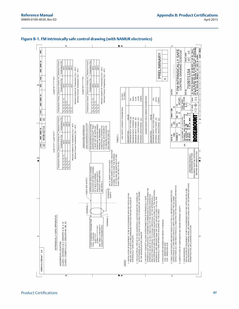
Reference Manual00809-0100-4030, Rev ED
Appendix B: Product CertificationsApril 2015
Figure B-1. FM intrinsically safe control drawing (with NAMUR electronics)
INTE
RN
AL
IND
UC
TAN
CE
(L
i)
0.06
mH
INTE
RN
AL
CA
PA
CIT
AN
CE
(C
i)
211n
FM
AX
IMU
M IN
PU
T P
OW
ER
(P
i)
0.1W
MA
XIM
UM
INP
UT
CU
RR
EN
T (Ii
)
3
2mA
MA
XIM
UM
INP
UT
VO
LTA
GE
(Ui)
15V
DE
SC
RIP
TIO
N
VA
LUE
TAB
LE 1
CLA
SS
I, Z
ON
ES
0,1
& 2
, GR
OU
PS
IIA
, IIB
, IIC
.C
LAS
S I,
DIV
ISIO
N 1
& 2
, GR
OU
PS
A, B
, C, D
.H
AZA
RD
OU
S L
OC
ATI
ON
.
I
NTR
INS
ICA
LLY
SA
FE A
PP
AR
ATU
S
C
AP
AC
ITA
NC
E (C
o ) A
ND
IND
UC
TAN
CE
(Lo
) IN
DIC
ATE
D O
N T
HE
AS
SO
CIA
TED
AP
PA
RA
TUS
.
CA
PA
CIT
AN
CE
(Ci )
AN
D IN
DU
CTA
NC
E (L
i ) M
US
T N
OT
EX
CE
ED
TH
E A
LLO
WE
D5.
CA
BLE
CA
PA
CIT
AN
CE
AN
D IN
DU
CTA
NC
E P
LUS
TH
E I.
S. A
PP
AR
ATU
S U
NP
RO
TEC
TED
4. F
OR
FU
RTH
ER
INFO
RM
ATI
ON
RE
FER
TO
MA
NU
AL:
IN
TRIN
SIC
ALL
Y S
AFE
AP
PA
RA
TUS
INC
LUD
ING
ALL
TH
E C
AB
LE.
A
PP
AR
ATU
S, A
RE
GR
EA
TER
TH
AN
TH
E T
OTA
L V
ALU
ES
Ci A
ND
Li O
F A
LL T
HE
SA
FE A
PP
AR
ATU
S A
ND
TH
E A
PP
RO
VE
D V
ALU
ES
OF
Co
AN
D L
o O
F TH
E A
SS
OC
IATE
D
AR
E L
ES
S T
HA
N O
R E
QU
AL
TO U
i (V
max
) A
ND
Ii (I
max
) O
F TH
E IN
TRIN
SIC
ALL
Y
A
PP
RO
VE
D V
ALU
ES
OF
Uo
(Voc
) A
ND
Io (I
oc )
OF
THE
AS
SO
CIA
TED
AP
PA
RA
TUS
AP
PA
RA
TUS
NO
T S
PE
CIF
ICA
LLY
EX
AM
INE
D IN
CO
MB
INA
TIO
N A
S A
SY
STE
M W
HE
N T
HE
3. T
HE
EN
TITY
CO
NC
EP
T A
LLO
WS
INTE
RC
ON
NE
CTI
ON
OF
INTR
INS
ICA
LLY
SA
FE
O
F TH
E A
PP
AR
ATU
S F
OR
1 M
INU
TE.
W
ITH
STA
ND
ING
AN
A.C
. TE
ST
VO
LTA
GE
OF
500V
RM
S T
O G
RO
UN
D O
R T
HE
FR
AM
E
2. T
HE
ELE
CTR
ICA
L C
IRC
UIT
IN T
HE
HA
ZAR
DO
US
LO
CA
TIO
N M
US
T B
E C
AP
AB
LE O
F
IN
TRIN
SIC
ALL
Y S
AFE
CIR
CU
ITS
.
AN
D 5
05, A
ND
ISA
RP
12.6
RE
CO
MM
EN
DE
D P
RA
CTI
CE
FO
R IN
STA
LLA
TIO
N O
F 1.
INS
TALL
ATI
ON
OF
EQ
UIP
ME
NT
TO B
E IN
AC
CO
RD
AN
CE
WIT
H N
EC
AR
TIC
LES
504
NO
TES
:-
DE
SC
RIP
TIO
N
VA
LUE
MA
XIM
UM
INP
UT
VO
LTA
GE
(Vm
ax)
15V
INTE
RN
AL
CA
PA
CIT
AN
CE
(C
i)
2
11nF
INTE
RN
AL
IND
UC
TAN
CE
(L
i)
0.
06m
H
7. N
ON
-INC
EN
DIV
E:-
IN
STA
LLA
TIO
N O
F E
QU
IPM
EN
T TO
BE
IN A
CC
OR
DA
NC
E W
ITH
NE
C A
RTI
CLE
S 5
01 &
505
.
NO
N-IN
CE
ND
IVE
FIE
LD W
IRIN
G S
HA
LL B
E P
ER
MIT
TED
US
ING
AN
Y O
F TH
E W
IRIN
G M
ETH
OD
S
PE
RM
ITTE
D F
OR
UN
CLA
SS
IFIE
D L
OC
ATI
ON
UN
IT E
NTI
TY C
ON
CE
PT
PA
RA
ME
TER
S
C
LI D
IV1
CLI
ZN
0,1
NO
NIN
CE
ND
IVE
FIE
LD W
IRIN
G P
AR
AM
ETE
RS
2120
: 00
809-
0100
-403
021
30 :
0080
9-01
00-4
130
T5, T
4, T
3, T
2, T
1T4
, T3,
T2,
T1
T3, T
2, T
1
Tem
pera
ture
Cla
sses
80°C
60°C
50°C
Tem
pera
ture
(Ta)
Max
imum
Am
bien
t Air
60°C
115°
C15
0°C
Tem
pera
ture
(Tp)
Max
imum
Pro
cess
T5, T
4, T
3, T
2, T
1T4
, T3,
T2,
T1
T3, T
2, T
1
Tem
pera
ture
Cla
sses
80°C
77°C
71°C
Tem
pera
ture
(Ta)
Max
imum
Am
bien
t Air
80°C
115°
C18
5°C
Tem
pera
ture
(Tp)
Max
imum
Pro
cess
T2, T
165
°C26
0°C
2120
***C
*I**
*, 2
120*
**K
*I**
*21
30N
**E
****
****
***I
5**
Min
imum
Pro
cess
Tem
pera
ture
(Tp)
= -4
0°C
Min
imum
Am
bien
t Air
Tem
pera
ture
(Ta)
= -4
0°C
Min
imum
Pro
cess
Tem
pera
ture
(Tp)
= -7
0°C
Min
imum
Am
bien
t Air
Tem
pera
ture
(Ta)
= -5
0°C
T5, T
4, T
3, T
2, T
1T4
, T3,
T2,
T1
T3, T
2, T
1
Tem
pera
ture
Cla
sses
80°C
69°C
50°C
Tem
pera
ture
(Ta)
Max
imum
Am
bien
t Air
80°C
115°
C18
0°C
Tem
pera
ture
(Tp)
Max
imum
Pro
cess
2130
N**
M**
****
****
*I5*
*
Min
imum
Pro
cess
Tem
pera
ture
(Tp)
= -4
0°C
Min
imum
Am
bien
t Air
Tem
pera
ture
(Ta)
= -5
0°C
CO
NC
EP
T P
AR
AM
ETE
RS
.S
EE
TA
BLE
1 F
OR
EN
TITY
2120
****
*I**
*TY
PE
: 212
0/21
30LO
OP
PO
WE
RE
D T
RA
NS
MIT
TER
TER
MIN
AL
2
TER
MIN
AL
1N
ON
-HA
ZAR
DO
US
LO
CA
TIO
N
AS
SO
CIA
TED
AP
PA
RA
TUS
PO
INT
ON
LY O
R N
OT
AT
ALL
.IF
FIT
TED
MA
Y B
E E
AR
THE
D A
T O
NE
IS U
SE
D.
IN T
HIS
CA
SE
TH
E S
CR
EE
NR
EQ
UIR
ED
WH
EN
A G
ALV
AN
IC IS
OLA
TOR
AN
I.S
. SA
FETY
EA
RTH
IS N
OT
SE
E N
OTE
3.
CO
NC
EP
T P
AR
AM
ETE
RS
ISO
LATO
R W
ITH
EN
TITY
OF
A M
ULT
I-CH
AN
NE
LIS
OLA
TOR
OR
ON
E C
HA
NN
EL
AP
PR
OV
ED
SIN
GLE
CH
AN
NE
L
EA
RTH
SC
RE
EN
CA
BLE
SE
E N
OTE
5
250V
RM
S O
R 2
50V
DC
.TO
GR
OU
ND
IN E
XC
ES
S O
FP
OTE
NTI
AL
WIT
H R
ES
PE
CT
CO
ND
ITIO
NS
A S
OU
RC
E O
FN
OR
MA
L O
R A
BN
OR
MA
LFR
OM
NO
R C
ON
TAIN
UN
DE
RIT
MU
ST
NO
T B
E S
UP
PLI
ED
UN
SP
EC
IFIE
D E
XC
EP
T TH
AT
NO
N-H
AZA
RD
OU
S L
OC
ATI
ON
2130
N**
****
****
****
I5**
6. S
UB
STI
TUTI
ON
OF
CO
MP
ON
EN
TS M
AY
IMP
AIR
INTR
INS
IC S
AFE
TY.
XX
mb
25X
0
1:1
6.3A
CA
DFM
INTR
INS
ICA
LLY
SA
FEC
ON
TRO
L D
RA
WIN
G 2
120/
2130
7109
7/11
5410
1/1
10M
OB
-027
1441
PR
ELI
MIN
AR
Y
CE
RTI
FIE
D P
RO
DU
CT.
ALT
ER
ATI
ON
S T
O T
HIS
DO
CU
ME
NT
MU
ST
BE
AP
PR
OV
ED
BE
FOR
E IM
PLE
ME
NTA
TIO
N
A
61Product Certifications
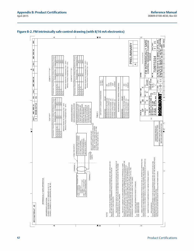
Reference Manual00809-0100-4030, Rev ED
Appendix B: Product CertificationsApril 2015
62
Figure B-2. FM intrinsically safe control drawing (with 8/16 mA electronics)
INTE
RN
AL
IND
UC
TAN
CE
(L
i)
0.03
5mH
INTE
RN
AL
CA
PA
CIT
AN
CE
(C
i)
12n
FM
AX
IMU
M IN
PU
T P
OW
ER
(P
i)
0.65
WM
AX
IMU
M IN
PU
T C
UR
RE
NT
(Ii)
93m
AM
AX
IMU
M IN
PU
T V
OLT
AG
E (U
i)
3
0VD
ES
CR
IPTI
ON
V
ALU
E
TAB
LE 1
CLA
SS
I, Z
ON
ES
0,1
& 2
, GR
OU
PS
IIA
, IIB
, IIC
.C
LAS
S I,
DIV
ISIO
N 1
& 2
, GR
OU
PS
A, B
, C, D
.H
AZA
RD
OU
S L
OC
ATI
ON
.
I
NTR
INS
ICA
LLY
SA
FE A
PP
AR
ATU
S
DE
SC
RIP
TIO
N
VA
LUE
MA
XIM
UM
INP
UT
VO
LTA
GE
(Vm
ax)
30V
INTE
RN
AL
CA
PA
CIT
AN
CE
(C
i)
1
2nF
INTE
RN
AL
IND
UC
TAN
CE
(L
i)
0.
035m
H
UN
IT E
NTI
TY C
ON
CE
PT
PA
RA
ME
TER
S
C
LI D
IV1
CLI
ZN
0,1
NO
NIN
CE
ND
IVE
FIE
LD W
IRIN
G P
AR
AM
ETE
RS
T5, T
4, T
3, T
2, T
1T4
, T3,
T2,
T1
T3, T
2, T
1
Tem
pera
ture
Cla
sses
80°C
60°C
50°C
Tem
pera
ture
(Ta)
Max
imum
Am
bien
t Air
60°C
115°
C15
0°C
Tem
pera
ture
(Tp)
Max
imum
Pro
cess
T5, T
4, T
3, T
2, T
1T4
, T3,
T2,
T1
T3, T
2, T
1
Tem
pera
ture
Cla
sses
80°C
77°C
71°C
Tem
pera
ture
(Ta)
Max
imum
Am
bien
t Air
80°C
115°
C18
5°C
Tem
pera
ture
(Tp)
Max
imum
Pro
cess
T2, T
165
°C26
0°C
2120
***H
*I**
*21
30M
**E
****
****
***I
5**
Min
imum
Pro
cess
Tem
pera
ture
(Tp)
= -4
0°C
Min
imum
Am
bien
t Air
Tem
pera
ture
(Ta)
= -4
0°C
Min
imum
Pro
cess
Tem
pera
ture
(Tp)
= -7
0°C
Min
imum
Am
bien
t Air
Tem
pera
ture
(Ta)
= -5
0°C
T5, T
4, T
3, T
2, T
1T4
, T3,
T2,
T1
T3, T
2, T
1
Tem
pera
ture
Cla
sses
80°C
69°C
50°C
Tem
pera
ture
(Ta)
Max
imum
Am
bien
t Air
80°C
115°
C18
0°C
Tem
pera
ture
(Tp)
Max
imum
Pro
cess
2130
M**
M**
****
****
*I5*
*
Min
imum
Pro
cess
Tem
pera
ture
(Tp)
= -4
0°C
Min
imum
Am
bien
t Air
Tem
pera
ture
(Ta)
= -5
0°C
CO
NC
EP
T P
AR
AM
ETE
RS
.S
EE
TA
BLE
1 F
OR
EN
TITY
2120
****
*I**
*TY
PE
: 212
0/21
30LO
OP
PO
WE
RE
D T
RA
NS
MIT
TER
TER
MIN
AL
2
TER
MIN
AL
1N
ON
-HA
ZAR
DO
US
LO
CA
TIO
N
AS
SO
CIA
TED
AP
PA
RA
TUS
PO
INT
ON
LY O
R N
OT
AT
ALL
.IF
FIT
TED
MA
Y B
E E
AR
THE
D A
T O
NE
IS U
SE
D.
IN T
HIS
CA
SE
TH
E S
CR
EE
NR
EQ
UIR
ED
WH
EN
A G
ALV
AN
IC IS
OLA
TOR
AN
I.S
. SA
FETY
EA
RTH
IS N
OT
SE
E N
OTE
3 &
NO
TE 7
CO
NC
EP
T P
AR
AM
ETE
RS
ISO
LATO
R W
ITH
EN
TITY
OF
A M
ULT
I-CH
AN
NE
LIS
OLA
TOR
OR
ON
E C
HA
NN
EL
AP
PR
OV
ED
SIN
GLE
CH
AN
NE
L
EA
RTH
SC
RE
EN
CA
BLE
SE
E N
OTE
5
250V
RM
S O
R 2
50V
DC
.TO
GR
OU
ND
IN E
XC
ES
S O
FP
OTE
NTI
AL
WIT
H R
ES
PE
CT
CO
ND
ITIO
NS
A S
OU
RC
E O
FN
OR
MA
L O
R A
BN
OR
MA
LFR
OM
NO
R C
ON
TAIN
UN
DE
RIT
MU
ST
NO
T B
E S
UP
PLI
ED
UN
SP
EC
IFIE
D E
XC
EP
T TH
AT
NO
N-H
AZA
RD
OU
S L
OC
ATI
ON
2130
M**
****
****
****
I5**
NO
TES
:
1.IN
STA
LLA
TIO
N O
F E
QU
IPM
EN
T TO
BE
IN A
CC
OR
DA
NC
E W
ITH
NE
C A
RTI
CLE
S 5
04A
ND
505
, AN
D IS
A R
P12
.6 R
EC
OM
ME
ND
ED
PR
AC
TIC
E F
OR
INS
TALL
ATI
ON
OF
INTR
INS
ICA
LLY
SA
FE C
IRC
UIT
S.
2.TH
E E
LEC
TRIC
AL
CIR
CU
IT IN
TH
E H
AZA
RD
OU
S L
OC
ATI
ON
MU
ST
BE
CA
PA
BLE
OF
WIT
HS
TAN
DIN
G A
N A
.C. T
ES
T V
OLT
AG
E O
F 50
0V R
MS
TO
GR
OU
ND
OR
TH
E F
RA
ME
OF
THE
AP
PA
RA
TUS
FO
R 1
MIN
UTE
.
3.TH
E E
NTI
TY C
ON
CE
PT
ALL
OW
S IN
TER
CO
NN
EC
TIO
N O
F IN
TRIN
SIC
ALL
Y S
AFE
AP
PA
RA
TUS
NO
T S
PE
CIF
ICA
LLY
EX
AM
INE
D IN
CO
MB
INA
TIO
N A
S A
SY
STE
M W
HE
N T
HE
AP
PR
OV
ED
VA
LUE
S O
F U
o (V
oc )
AN
D Io
(Ioc
) O
F TH
E A
SS
OC
IATE
D A
PP
AR
ATU
SA
RE
LE
SS
TH
AN
OR
EQ
UA
L TO
Ui (
Vm
ax )
AN
D Ii
(Im
ax )
OF
THE
INTR
INS
ICA
LLY
SA
FE A
PP
AR
ATU
S A
ND
TH
E A
PP
RO
VE
D V
ALU
ES
OF
Co
AN
D L
o O
F TH
E A
SS
OC
IATE
DA
PP
AR
ATU
S, A
RE
GR
EA
TER
TH
AN
TH
E T
OTA
L V
ALU
ES
Ci A
ND
Li O
F A
LL T
HE
INTR
INS
ICA
LLY
SA
FE A
PP
AR
ATU
S IN
CLU
DIN
G A
LL T
HE
CA
BLE
.
4.FO
R F
UR
THE
R IN
FOR
MA
TIO
N R
EFE
R T
O M
AN
UA
L:21
20 :
0080
9-01
00-4
030
2130
: 00
809-
0100
-413
0
5.C
AB
LE C
AP
AC
ITA
NC
E A
ND
IND
UC
TAN
CE
PLU
S T
HE
I.S
. AP
PA
RA
TUS
UN
PR
OTE
CTE
DC
AP
AC
ITA
NC
E (C
i ) A
ND
IND
UC
TAN
CE
(Li )
MU
ST
NO
T E
XC
EE
D T
HE
ALL
OW
ED
CA
PA
CIT
AN
CE
(Co
) AN
D IN
DU
CTA
NC
E (L
o ) I
ND
ICA
TED
ON
TH
E A
SS
OC
IATE
D A
PP
AR
ATU
S.
6.S
UB
STI
TUTI
ON
OF
CO
MP
ON
EN
TS M
AY
IMP
AIR
INTR
INS
IC S
AFE
TY.
7.N
ON
-INC
EN
DIV
E:-
INS
TALL
ATI
ON
OF
EQ
UIP
ME
NT
TO B
E IN
AC
CO
RD
AN
CE
WIT
H N
EC
AR
TIC
LES
501
& 5
05.
NO
N-IN
CE
ND
IVE
FIE
LD W
IRIN
G S
HA
LL B
E P
ER
MIT
TED
US
ING
AN
Y O
F TH
E W
IRIN
G M
ETH
OD
SP
ER
MIT
TED
FO
R U
NC
LAS
SIF
IED
LO
CA
TIO
NTH
E IS
OLA
TOR
CA
N B
E R
EP
LAC
ED
BY
A R
EG
ULA
TED
PO
WE
R S
OU
RC
E
XX
GP
38X
0
1:1
6.3A
CA
DFM
INTR
INS
ICA
LLY
SA
FEC
ON
TRO
L D
RA
WIN
G 2
120/
2130
7109
7/13
143
1/1
3M
OB
-027
1441
APR
ELI
MIN
AR
Y
8/16
mA
CE
RTI
FIE
D P
RO
DU
CT.
ALT
ER
ATI
ON
S T
O T
HIS
DO
CU
ME
NT
MU
ST
BE
AP
PR
OV
ED
BE
FOR
E IM
PLE
ME
NTA
TIO
N
Product Certifications
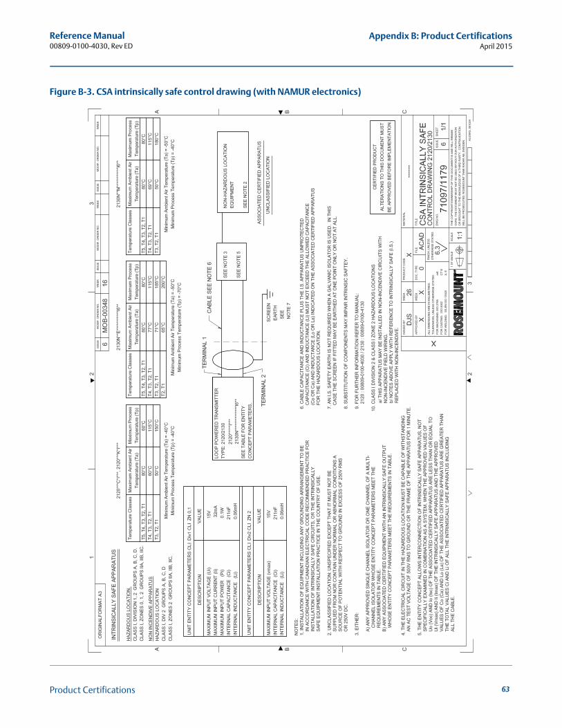
Reference Manual00809-0100-4030, Rev ED
Appendix B: Product CertificationsApril 2015
Figure B-3. CSA intrinsically safe control drawing (with NAMUR electronics)
63Product Certifications
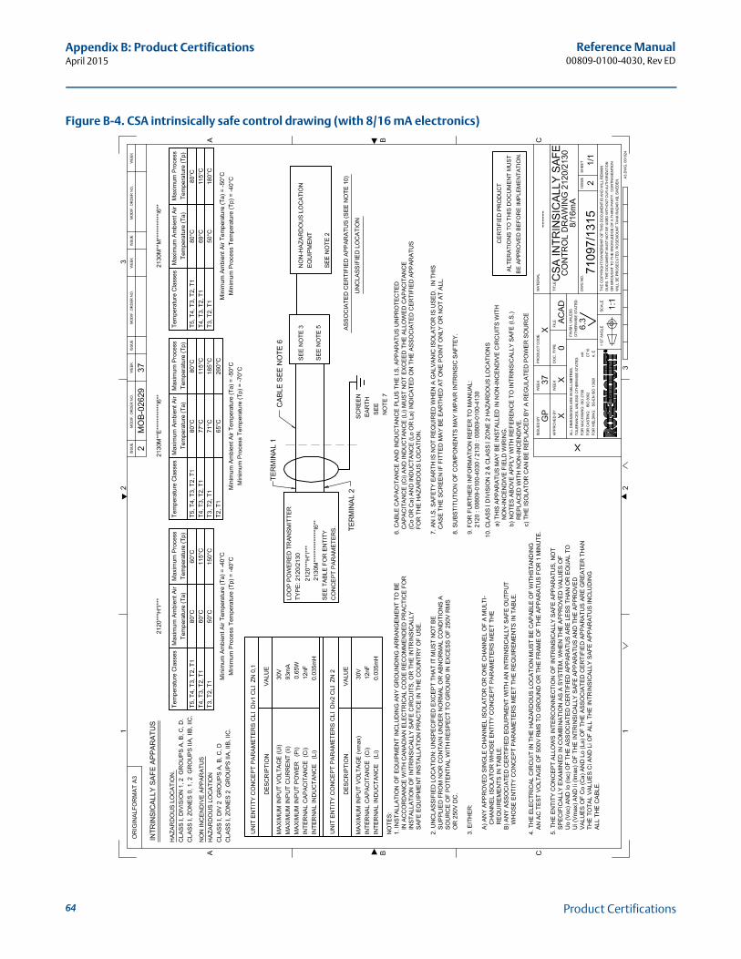
Reference Manual00809-0100-4030, Rev ED
Appendix B: Product CertificationsApril 2015
64
Figure B-4. CSA intrinsically safe control drawing (with 8/16 mA electronics)
Product Certifications
Reference Manual00809-0100-4030, Rev ED
Appendix B: Product CertificationsApril 2015
B.10.2 European approvals
ATEX flameproof approvals
E1 Certificate: Sira 05ATEX1129XFlameproof and dust-proof:ATEX Marking II 1/2 G DEx d IIC T6...T2 Ga/Gb, Ex tb IIIC T85 °C...T265 °C Db
Instructions specific to hazardous area installations (E1 and E7)Model numbers covered: 2120*****E1X**, 2120*****E1S**, 2120*****E7X**, 2120*****E7S**(“*” indicates options in construction, function and materials – see Table A-7 on page A-48).
The following instructions apply to the equipment covered by certificates numberedSira 05ATEX1129X and IECEx SIR 06.0051X:
1. The equipment may be used with flammable gases and vapors with apparatus groups IIA, IIB, and IIC, and with temperature classes T1, T2, T3, T4, T5, and T6 [IECEx: in Zones 1 and 2. The probe may be installed in a Zone 0 vessel]. The temperature class of the installation will be determined from the higher of the process or ambient temperature.
2. The equipment may be used in a hazardous area with explosive dusts with apparatus groups IIIC, IIIB, and IIIA. The maximum surface temperature of the installation will be determined from the higher of the process or ambient temperature.
3. The equipment has not been assessed as a safety related device (as referred to by Directive 94/9/EC Annex II, clause 1.5).
4. Installation of this equipment shall be carried out by suitably trained personnel, in accordance with the applicable code of practice.
5. Inspection and maintenance of this equipment shall be carried out by suitably trained personnel, in accordance with the applicable code of practice.
6. The user should not repair this equipment.
7. The certification of this equipment relies upon the following materials used in its construction:
Body: Aluminum Alloy (ASTM B85 360.0) or 316 Stainless SteelCover: Aluminum Alloy (ASTM B85 360.0) or 316 Stainless SteelProbe: 316 Stainless Steel, or Alloy C276 (UNS N10276) and Alloy C (UNS N10002)Probe Filling: PerliteCover Seal: Silicone
8. If the equipment is likely to come into contact with aggressive substances, it is the responsibility of the user to take suitable precautions that prevent it from being adversely affected, thus ensuring that the type of protection is not compromised.
Aggressive substances: e.g. acidic liquids or gases that may attack metals, or solvents that may affect polymeric materialsSuitable precautions: e.g. regular checks as part of routine inspections or establishing from the material’s data sheet that it is resistant to specific chemicals
65Product Certifications
Reference Manual00809-0100-4030, Rev ED
Appendix B: Product CertificationsApril 2015
66
9. It is the responsibility of the user to ensure:
a. The voltage and current limits are not exceeded.
b. That the joint requirements between the probe and the vessel tank are compatible with the process media.
c. That the joint tightness is correct for the joint material used.
d. That only suitably certified cable entry devices will be utilized when connecting this equipment.
e. That any unused cable entries are sealed with suitably certified stopping plugs.
10. The probe fork is subjected to small vibration stresses as part of its normal function. As this provides a partition wall, it is recommended that the fork should be inspected every 2 years for signs of defects.
11. Technical data
a. Coding:ATEX: II 1/2 G D, Ex d IIC T6...T2 Ga/Gb, Ex tb IIIC T85°C...T265°C DbIECEx: Ex d IIC T6...T2 Ga/Gb, Ex tb IIIC T85°C...T265°C Db
b. Temperature:
2120*****E1X**, 2120*****E1S**, 2120*****E7X**, 2120*****E7S**:
Minimum ambient air temperature (Ta) = –40°CMinimum process temperature (Tp) = –40°C
c. Pressure: Must not exceed the rating of the coupling/flange fitted.
d. For electrical details and pressure ratings, refer to Specifications on page 37.
e. Year of manufacture: Printed on product label.
12. Cable selection
It is the responsibility of the user to ensure that suitably temperature rated cable is used. The table below is a guide to selection:
13. Special conditions of use
a. The user is to ensure the ambient air temperature (Ta) and the process temperature (Tp) are within the range detailed above for the T class of the specific flammable gases or vapors present.
b. The user is to ensure the ambient air temperature (Ta) and the process temperature (Tp) are within the range detailed above for the maximum surface temperature of the specific flammable dusts present.
14. Manufacturer: Rosemount Measurement Ltd., 158 Edinburgh Avenue, Slough, Berkshire, SL1 4UE, UK
Temperature Classes
Maximum Surface Temperature (T)
Maximum Ambient Air Temperature (Ta)
Maximum Process Temperature (Tp)
T6, T5, T4, T3, T2, T1 T85 °C 75 °C 75 °C
T5, T4, T3, T2, T1 T100 °C 70 °C 90 °C
T4, T3, T2, T1 T135 °C 65 °C 125 °C
T3, T2, T1 T160 °C 50 °C 150 °C
T Class Cable Temperature Rating
T6 Above 85 °C
T5 Above 100 °C
T4 Above 135 °C
T3 Above 160 °C
Product Certifications
Reference Manual00809-0100-4030, Rev ED
Appendix B: Product CertificationsApril 2015
ATEX intrinsically safe approval
NoteA certified isolating amplifier to IEC 60947-5-6 is required for intrinsic safety if the NAMUR electronics is used in a hazardous area installation (see below)
A certified intrinsically safe barrier is required for intrinsic safety if the 8/16 mA electronics is used in a hazardous area installation (see below)
I1 Certificate: Sira 05ATEX2130XIntrinsically Safe for gas and dust environments:ATEX Marking II 1 G DEx ia IIC T5...T2 GaEx ia IIIC T85°C...T265°C Da
Instructions specific to hazardous area installations (I1 and I7)Model numbers covered:2120***H*I1**, 2120***C*I1**, 2120***K*I1**2120***H*I7**, 2120***C*I7**, 2120***K*I7*(“*” indicates options in construction, function and materials – see Table A-7 on page 48)
The following instructions apply to the equipment covered by certificates numberedSira 05ATEX2130X and IECEx Sir 06.0070X:
1. The Intrinsically Safe approved versions of the 2120 may be used in a hazardous area with flammable gases and vapors with apparatus groups IIC, IIB, and IIA, and with temperature classes T1, T2, T3, T4, and T5 [IECEx: in Zones 0, 1, and 2].
The temperature class of the installation will be determined from the higher of the process or ambient temperature.
2. The equipment may be used in a hazardous area with explosive dusts with apparatus groups IIIC, IIIB, and IIIA [IECEx: in Zones 20, 21, and 22].
The maximum surface temperature of the installation will be determined from the higher of the process or ambient temperature.
3. It is a special condition of the certification that the temperature of the electronics housing is in the range of –50 to +80 °C. It must not be used outside this range. It will be necessary to limit the external ambient temperature if the process temperature is high.(See “Technical Data” below).
4. Suitably trained personnel shall carry out installation in accordance with the applicable code of practice.
5. The user should not repair this equipment.
6. If the equipment is likely to come into contact with aggressive substances, it is the responsibility of the user to take suitable precautions that prevent it from being adversely affected, thus ensuring that the type of protection is not compromised.
Aggressive substances: e.g. acidic liquids or gases that may attack metals or solvents that may affect polymeric materials.Suitable precautions: e.g. regular checks as part of routine inspections or establishing from the material’s data sheet that it is resistant to specific chemicals.
67Product Certifications
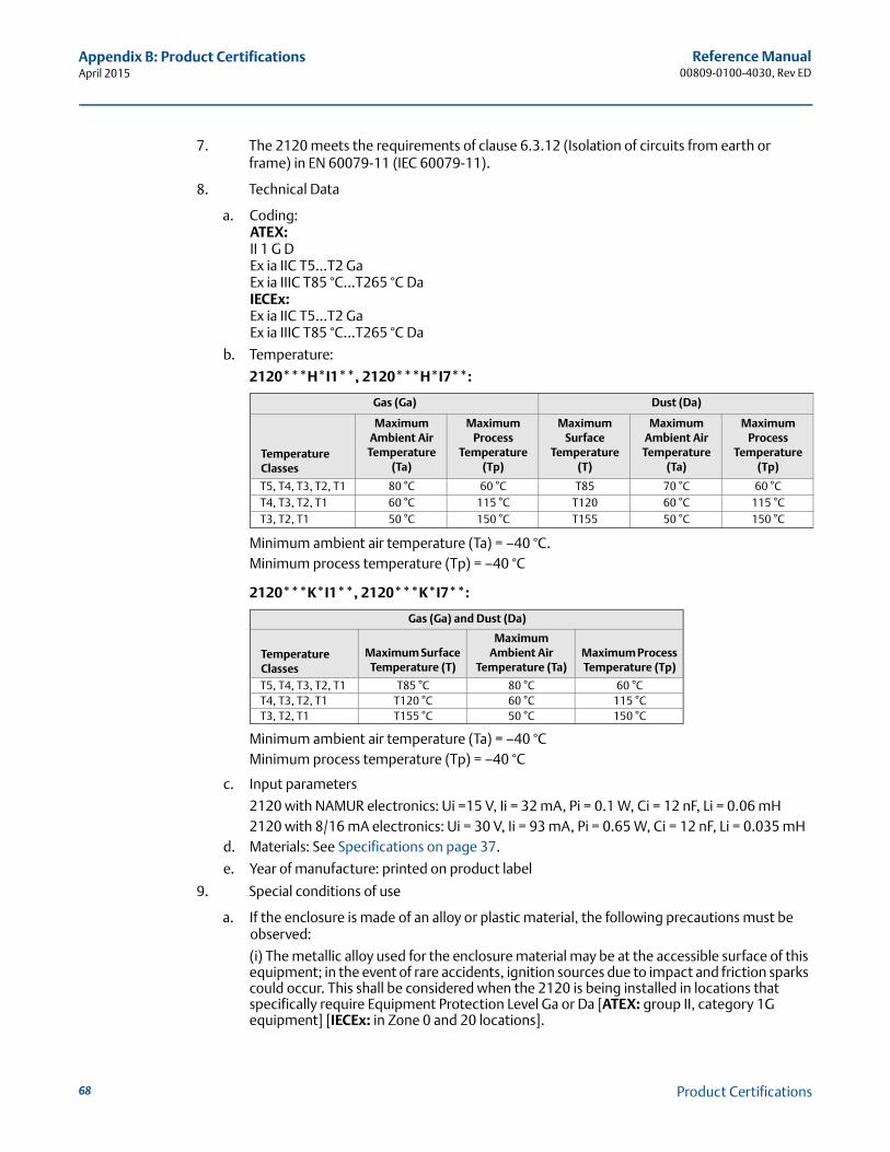
Reference Manual00809-0100-4030, Rev ED
Appendix B: Product CertificationsApril 2015
68
7. The 2120 meets the requirements of clause 6.3.12 (Isolation of circuits from earth or frame) in EN 60079-11 (IEC 60079-11).
8. Technical Data
a. Coding:ATEX: II 1 G DEx ia IIC T5...T2 GaEx ia IIIC T85 °C...T265 °C DaIECEx: Ex ia IIC T5...T2 GaEx ia IIIC T85 °C...T265 °C Da
b. Temperature:
2120***H*I1**, 2120***H*I7**:
Minimum ambient air temperature (Ta) = –40 °C.Minimum process temperature (Tp) = –40 °C
2120***K*I1**, 2120***K*I7**:
Minimum ambient air temperature (Ta) = –40 °CMinimum process temperature (Tp) = –40 °C
c. Input parameters
2120 with NAMUR electronics: Ui =15 V, Ii = 32 mA, Pi = 0.1 W, Ci = 12 nF, Li = 0.06 mH2120 with 8/16 mA electronics: Ui = 30 V, Ii = 93 mA, Pi = 0.65 W, Ci = 12 nF, Li = 0.035 mH
d. Materials: See Specifications on page 37.
e. Year of manufacture: printed on product label
9. Special conditions of use
a. If the enclosure is made of an alloy or plastic material, the following precautions must be observed:
(i) The metallic alloy used for the enclosure material may be at the accessible surface of this equipment; in the event of rare accidents, ignition sources due to impact and friction sparks could occur. This shall be considered when the 2120 is being installed in locations that specifically require Equipment Protection Level Ga or Da [ATEX: group II, category 1G equipment] [IECEx: in Zone 0 and 20 locations].
Gas (Ga) Dust (Da)
Temperature Classes
Maximum Ambient Air
Temperature (Ta)
Maximum Process
Temperature (Tp)
Maximum Surface
Temperature (T)
Maximum Ambient Air
Temperature (Ta)
Maximum Process
Temperature (Tp)
T5, T4, T3, T2, T1 80 °C 60 °C T85 70 °C 60 °CT4, T3, T2, T1 60 °C 115 °C T120 60 °C 115 °CT3, T2, T1 50 °C 150 °C T155 50 °C 150 °C
Gas (Ga) and Dust (Da)
Temperature Classes
Maximum Surface Temperature (T)
Maximum Ambient Air
Temperature (Ta)Maximum Process Temperature (Tp)
T5, T4, T3, T2, T1 T85 °C 80 °C 60 °CT4, T3, T2, T1 T120 °C 60 °C 115 °CT3, T2, T1 T155 °C 50 °C 150 °C
Product Certifications
Reference Manual00809-0100-4030, Rev ED
Appendix B: Product CertificationsApril 2015
(ii) Under certain extreme circumstances, the non-metallic parts incorporated in the enclosure of the 2120 may generate an ignition-capable level of electrostatic charge. Therefore, when they are used for applications that specifically require Equipment Protection Level Ga or Da [ATEX: group II, category 1G equipment] [IECEx: in Zone 0 and 20 locations], the 2120 shall not be installed in a location where the external conditions are conducive to the build-up of electrostatic charge on such surfaces. Additionally, the 2120 shall only be cleaned with a damp cloth.
b. Ensure the ambient air temperature (Ta) and the process temperature (Tp) are within the range detailed above for the T class of the specific flammable gases or vapors present.
c. Ensure the ambient air temperature (Ta) and the process temperature (Tp) are within the range detailed above for the maximum surface temperature of the specific flammable dusts present.
10. ManufacturerRosemount Measurement Limited, 158 Edinburgh Avenue, Slough, Berkshire, SL1 4UE, United Kingdom
69Product Certifications
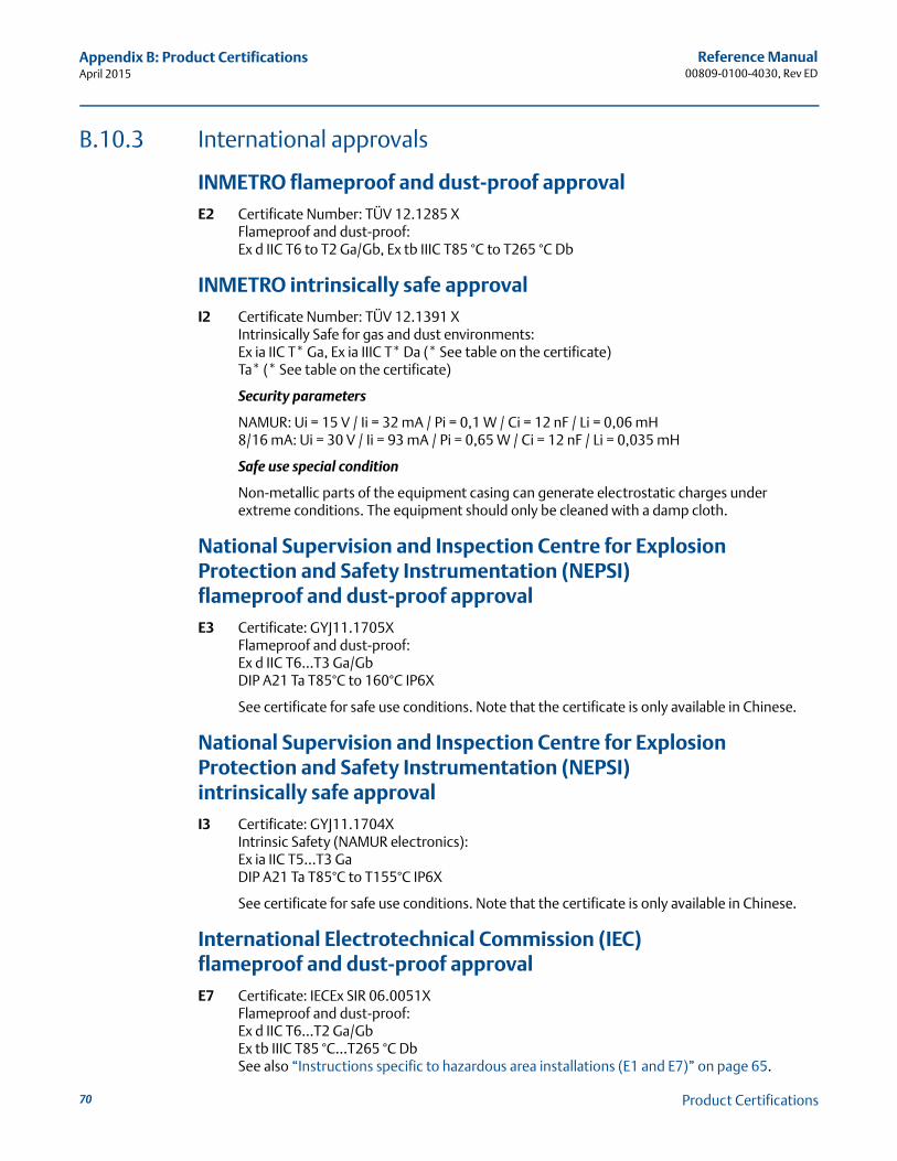
Reference Manual00809-0100-4030, Rev ED
Appendix B: Product CertificationsApril 2015
70
B.10.3 International approvals
INMETRO flameproof and dust-proof approvalE2 Certificate Number: TÜV 12.1285 X
Flameproof and dust-proof:Ex d IIC T6 to T2 Ga/Gb, Ex tb IIIC T85 °C to T265 °C Db
INMETRO intrinsically safe approvalI2 Certificate Number: TÜV 12.1391 X
Intrinsically Safe for gas and dust environments:Ex ia IIC T* Ga, Ex ia IIIC T* Da (* See table on the certificate)Ta* (* See table on the certificate)
Security parameters
NAMUR: Ui = 15 V / Ii = 32 mA / Pi = 0,1 W / Ci = 12 nF / Li = 0,06 mH8/16 mA: Ui = 30 V / Ii = 93 mA / Pi = 0,65 W / Ci = 12 nF / Li = 0,035 mH
Safe use special condition
Non-metallic parts of the equipment casing can generate electrostatic charges under extreme conditions. The equipment should only be cleaned with a damp cloth.
National Supervision and Inspection Centre for Explosion Protection and Safety Instrumentation (NEPSI) flameproof and dust-proof approvalE3 Certificate: GYJ11.1705X
Flameproof and dust-proof:Ex d IIC T6...T3 Ga/GbDIP A21 Ta T85°C to 160°C IP6X
See certificate for safe use conditions. Note that the certificate is only available in Chinese.
National Supervision and Inspection Centre for Explosion Protection and Safety Instrumentation (NEPSI) intrinsically safe approvalI3 Certificate: GYJ11.1704X
Intrinsic Safety (NAMUR electronics):Ex ia IIC T5...T3 GaDIP A21 Ta T85°C to T155°C IP6X
See certificate for safe use conditions. Note that the certificate is only available in Chinese.
International Electrotechnical Commission (IEC)flameproof and dust-proof approvalE7 Certificate: IECEx SIR 06.0051X
Flameproof and dust-proof:Ex d IIC T6...T2 Ga/GbEx tb IIIC T85 °C...T265 °C DbSee also “Instructions specific to hazardous area installations (E1 and E7)” on page 65.
Product Certifications
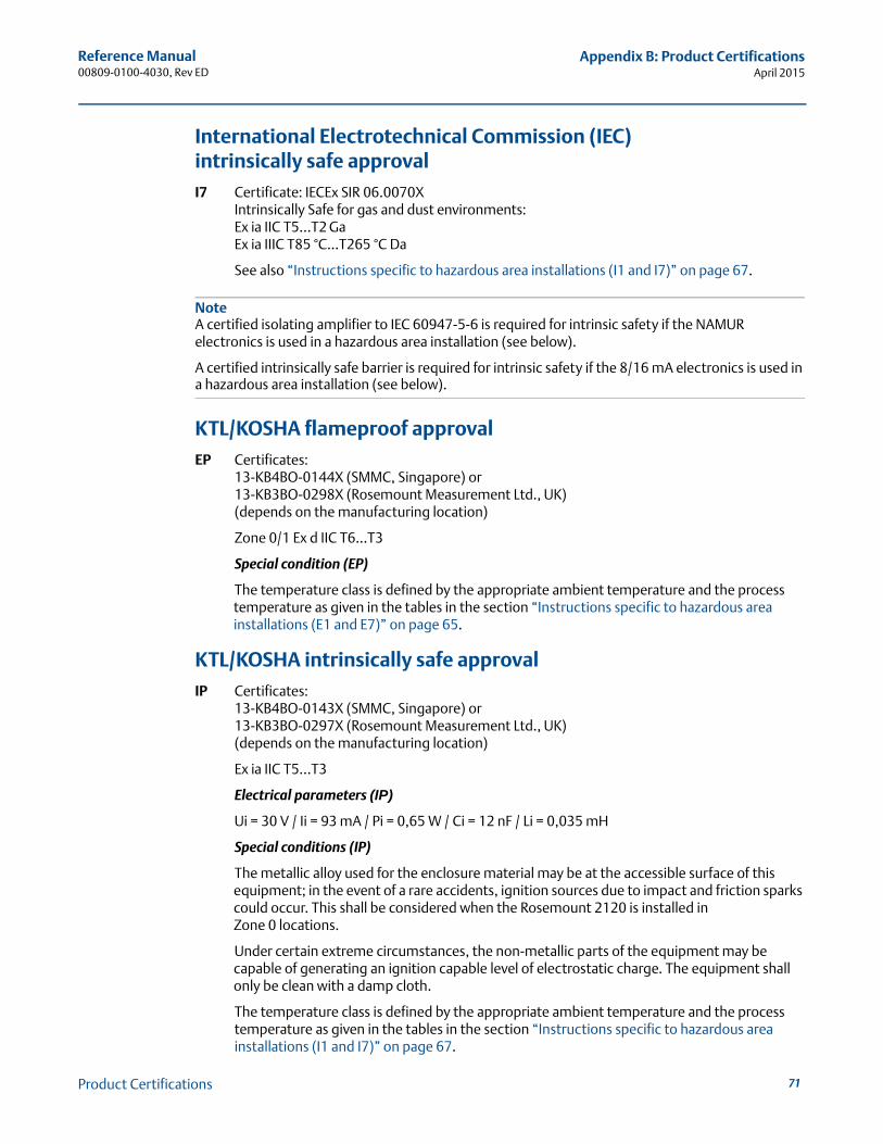
Reference Manual00809-0100-4030, Rev ED
Appendix B: Product CertificationsApril 2015
International Electrotechnical Commission (IEC)intrinsically safe approvalI7 Certificate: IECEx SIR 06.0070X
Intrinsically Safe for gas and dust environments:Ex ia IIC T5...T2 GaEx ia IIIC T85 °C...T265 °C Da
See also “Instructions specific to hazardous area installations (I1 and I7)” on page 67.
NoteA certified isolating amplifier to IEC 60947-5-6 is required for intrinsic safety if the NAMUR electronics is used in a hazardous area installation (see below).
A certified intrinsically safe barrier is required for intrinsic safety if the 8/16 mA electronics is used in a hazardous area installation (see below).
KTL/KOSHA flameproof approvalEP Certificates:
13-KB4BO-0144X (SMMC, Singapore) or13-KB3BO-0298X (Rosemount Measurement Ltd., UK)(depends on the manufacturing location)
Zone 0/1 Ex d IIC T6...T3
Special condition (EP)
The temperature class is defined by the appropriate ambient temperature and the process temperature as given in the tables in the section “Instructions specific to hazardous area installations (E1 and E7)” on page 65.
KTL/KOSHA intrinsically safe approvalIP Certificates:
13-KB4BO-0143X (SMMC, Singapore) or13-KB3BO-0297X (Rosemount Measurement Ltd., UK)(depends on the manufacturing location)
Ex ia IIC T5...T3
Electrical parameters (IP)
Ui = 30 V / Ii = 93 mA / Pi = 0,65 W / Ci = 12 nF / Li = 0,035 mH
Special conditions (IP)
The metallic alloy used for the enclosure material may be at the accessible surface of this equipment; in the event of a rare accidents, ignition sources due to impact and friction sparks could occur. This shall be considered when the Rosemount 2120 is installed in Zone 0 locations.
Under certain extreme circumstances, the non-metallic parts of the equipment may be capable of generating an ignition capable level of electrostatic charge. The equipment shall only be clean with a damp cloth.
The temperature class is defined by the appropriate ambient temperature and the process temperature as given in the tables in the section “Instructions specific to hazardous area installations (I1 and I7)” on page 67.
71Product Certifications
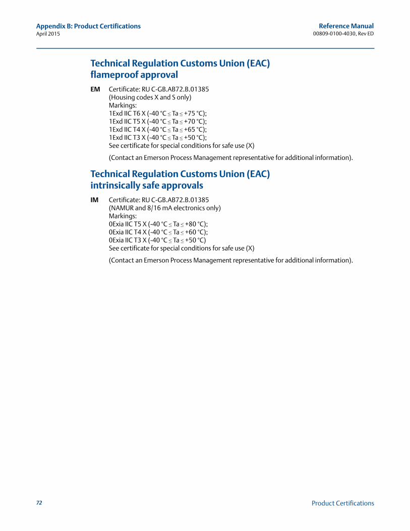
Reference Manual00809-0100-4030, Rev ED
Appendix B: Product CertificationsApril 2015
72
Technical Regulation Customs Union (EAC)flameproof approvalEM Certificate: RU C-GB.AB72.B.01385
(Housing codes X and S only)Markings:1Exd IIC T6 X (-40 °C ≤ Ta ≤ +75 °C);1Exd IIC T5 X (-40 °C ≤ Ta ≤ +70 °C);1Exd IIC T4 X (-40 °C ≤ Ta ≤ +65 °C);1Exd IIC T3 X (-40 °C ≤ Ta ≤ +50 °C);See certificate for special conditions for safe use (X)
(Contact an Emerson Process Management representative for additional information).
Technical Regulation Customs Union (EAC)intrinsically safe approvalsIM Certificate: RU C-GB.AB72.B.01385
(NAMUR and 8/16 mA electronics only)Markings:0Exia IIC T5 X (-40 °C ≤ Ta ≤ +80 °C);0Exia IIC T4 X (-40 °C ≤ Ta ≤ +60 °C);0Exia IIC T3 X (-40 °C ≤ Ta ≤ +50 °C)See certificate for special conditions for safe use (X)
(Contact an Emerson Process Management representative for additional information).
Product Certifications


Reference Manual00809-0100-4030, Rev ED
April 2015
Global HeadquartersEmerson Process Management 6021 Innovation BlvdShakopee, MN 55379, USA
+1 800 999 9307 or +1 952 906 8888+1 952 949 7001 [email protected]
North America Regional OfficeEmerson Process Management 8200 Market Blvd.Chanhassen, MN 55317, USA
+1 800 999 9307 or +1 952 906 8888+1 952 949 7001 [email protected]
Latin America Regional OfficeEmerson Process Management 1300 Concord Terrace, Suite 400Sunrise, Florida, 33323, USA
+1 954 846 5030+1 954 846 [email protected]
Europe Regional OfficeEmerson Process Management Europe GmbHNeuhofstrasse 19a P.O. Box 1046CH 6340 BaarSwitzerland
+41 (0) 41 768 6111+41 (0) 41 768 6300 [email protected]
Asia Pacific Regional OfficeEmerson Process Management Asia Pacific Pte Ltd1 Pandan CrescentSingapore 128461
+65 6777 8211+65 6777 0947 [email protected]
Middle East and Africa Regional OfficeEmerson Process Management Emerson FZE P.O. Box 17033,Jebel Ali Free Zone - South 2Dubai, United Arab Emirates
+971 4 8118100+971 4 8865465 [email protected]
Standard Terms and Conditions of Sale can be found at: www.rosemount.com\terms_of_sale.The Emerson logo is a trademark and service mark of Emerson Electric Co.Rosemount and Rosemount logotype are registered trademarks of Rosemount Inc.All other marks are the property of their respective owners.© 2015 Rosemount\ Inc. All rights reserved.