Embed Size (px)
Citation preview

1
MANUALSERVICEGATE V2Installation and use
REMOTE ENGINEER BV IT VEGELINSKAMPKE 11 8491 PD AKKRUM +31 566 796 515 [email protected]

2

3
Table of contents
Getting started 4
Login 5 Status 7 System 12 Services 17 Network 18 Admin 29 Leds 30 Router reset & WIFI 31 Technical support 32 Declaration of Conformity 33 Warranty 35

4
Getting started
The ServiceGate V2 is developed as part of the Remote Engineer Support solution.The associated Client software creates a VPN connection to the ServiceGate V2 that you have selected. Your PC is at that moment “directly” connected to the devices connected to the ServiceGate V2.
Essentials:
1. A ServiceGate V2 The ServiceGate V2 is supplied with power & I / O connectors, a network cable and a Wi-Fi antenna.
2. A internetbrowser TheServiceGateV2canbeconfiguredusingaWebbrowser.Thismaybe any Internet browser. Remote Engineer recommends using Google Chrome.
3. A computer to connect to the ServiceGate V2.

5
Login
ToconfiguretheServiceGateV2,followthenextsteps:
1. Connect the ServiceGate to a voltage source of 8-65 VDC.2. Connect one of the LAN ports of the ServiceGate to your PC.3. Start your Web browser and enter in the default IP address (10.195.0.1 or the agreed IP Address) of the ServiceGate, as shown in the image below.
4. The following login screen appears after pressing ENTER.

6
Login
5. You can now login with the default username and password (Admin / REAd min) or with your own username and password combination.

7
Status
If the login was successful, the ServiceGate V2 status overview screen appears. You are now in the Status menu and have the choice to go to another menu or submenu. If you choose a different menu, it will open with a list of submenus.
Thescreenaboveshowsinformationaboutthefirmwareversionnumber,howmuchworking memory is available, and which networks and services are available.
Overview

8
Status
Usingthisscreenyoucanseeanoverviewofthefirewallrulesthatareactiveandtheir associated counters. You can reset these counters. This is also done by restart-ingthefirewall.
Firewall
9
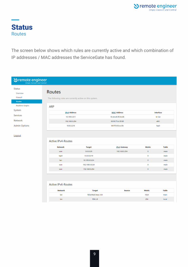
Status
The screen below shows which rules are currently active and which combination of IP addresses / MAC addresses the ServiceGate has found.
Routes

10
Status
TheServiceGateV2keepstrackofthecurrentload,trafficandwhatthesystemdoes.
Realtime charts

11
StatusRealtime charts

12
System
HereyoucanconfigurethebasicaspectsoftheServiceGate,V2likeit’shostnameor the timezone.

13
System
Using this screen you can backup all settings of the ServiceGate V2 or to reset them. WiththeFlashnewfirmwareimagefunction,youcanupdatetheServiceGatewithanewversionofthefirmwaretoresolveissuesoraddnewfunctionality.
InhettabbladConfigurationkuntuaangevenwelkeinstellingenenbestandenmeeworden genomen bij het maken van de backup.
Backup & Flash

14
SysteemBackup & Flash

15
SysteemBackup & Flash

16
System
When using the reboot button on this screen, you will invoke a reboot of the ServiceGate V2.
Reboot

17
Services
UsingthisscreenyoucanconfigureaforcedrebootwhentheInternetconnectionhas been lost for a certain period of time. By default, this option is disabled.
Watchcat

18
Network
This screen shows you a overview of the different interfaces of the ServiceGate V2. You can see each type of interface, how much data has been consumed and how long the interface is active.
By default, the ServiceGate V2 is provided with the most common settings. If you want to view or change the settings of an interface, you can select the appropriate function.Youcanalsostoporstartaninterfaceconfigured.If you want, an interface can be removed.Note: Stopping LAN interface is not recommended.
Interfaces

19
Network
UsingthisscreenyoucanconfigurehowtheWANportoftheServiceGateV2shouldwork by selecting the desired protocol. The possible options and settings that are displayed depend on the selected protocol.
Change interface WAN
20
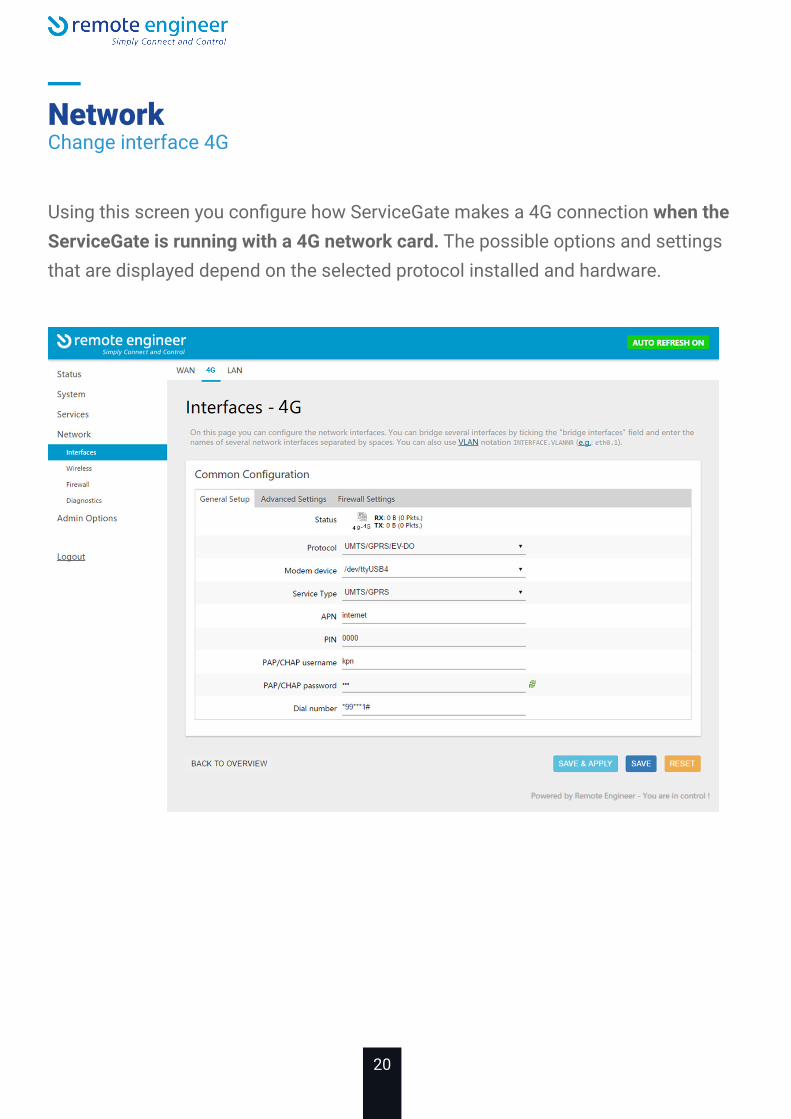
NetworkChange interface 4G
UsingthisscreenyouconfigurehowServiceGatemakesa4Gconnectionwhen the ServiceGate is running with a 4G network card. The possible options and settings that are displayed depend on the selected protocol installed and hardware.

21
NetworkChange interface 4G
If you want to use the 4G interface for internet access, it is important to connect the firewallzonetotheWAN/4G.ThisisaccomplishedbyselectingtheFirewallSet-tings tab and selecting the WAN / 4G zone. Then press Save & Apply, to activate the changes so the ServiceGate will activate it immediately.

22
Network
UsingthisscreenyouconfigurehowtheLANportsoftheServiceGateV2mustworkand whether the ServiceGate V2 should serve as a DHCP Server for connected devices.
Change interface LAN

23
Network
Using this screen you can setup the ServiceGate Wi-Fi. With the Disable function you can turn off the Wi-Fi.
Interface wireless

24
Network
Using this screen you can enter the Wi-Fi encryption and key.By default, the key is 0527712049.
If you want to customize the Wi-Fi SSID, select the General Setup tab of the Interface Configuration.
Change wireless

25
Network
Usingthisscreenyoucanconfigurezonesforyournetworktocontroldatatraffic.
Firewall, Zone settings

26
Network
Port forwarding is set by selecting the Port Forwards tab.
You can specify a logical name for the rule, which protocol it concerns, which zone youmean,plustheportnumberfromwhichitisforwarded,tofinallyindicatewhichIP address and which port the package should be sent to.
Ifallthisisspecified,presstheAddbuttontoconfirmtheforwardandthenSave&Apply to immediately activate and save the forward.
Firewall, Port forwards

27
Network
UsingthisscreenallowsyoutospecifyNATrulesthatalsoconfigurethefirewallanddefinedifferentpoliciesbetweenthedifferentzones.Examplesareopeningaportordenyingdatatrafficfromaparticularhost.
Firewall,Trafficrules

28
Network
Using this screen you can easily test whether the ServiceGate V2 is connected to the Internet.
Diagnose

29
Admin
Using this screen you can change the Admin User Password.
Password

30
LEDS
Below an overview of the LED functions.
1. POWEROn = electric pressureOff = no electric pressure
2. WLAN Enabled (blue)On = enabledOff = disabled
3. WLANOn = enabledOff = disabledBlink = data
4. RE-UPOn = onlineOff=offlineBlink = Factory defaults / Reset 3.
1.
4.
2.

31
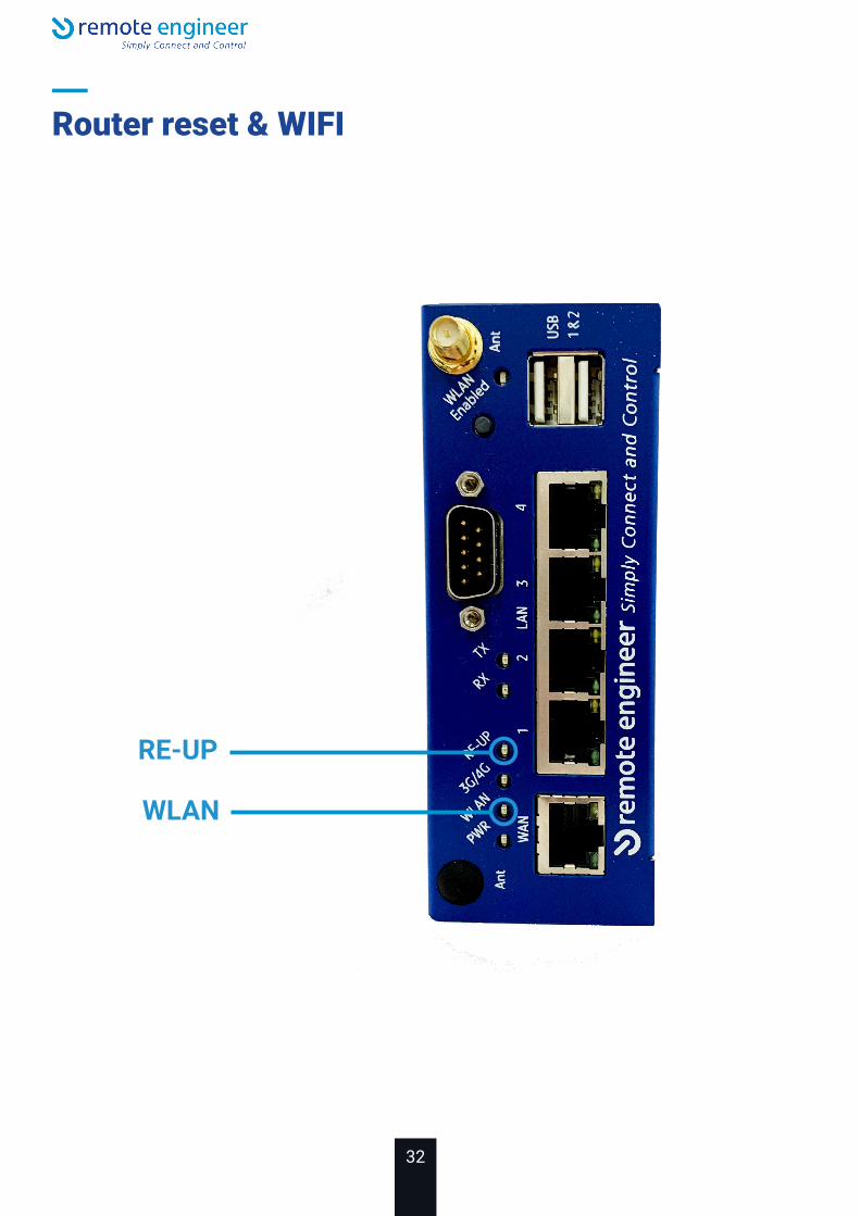
Router reset & WIFI
Resetting the router to default settingsToperformafactoryreset,firstswitchontherouter,thenfollowthestepsbelow.
Press the RESET button less than 10 seconds and the router will restart. When the RESET button is pressed for more than 30 seconds, the factory defaults of the cus-tomerareloadedviatheInternet.Loadingthesedefaultsettingswilltakeaboutfiveminutes. The router will reboot after receiving the settings and go online.
During the reset procedure the RE-UP light (green) will blink slowly. If the router connects to the Remote Engineer server, the RE-UP light will blink rapidly and default settings are loaded.
After the router is reset the default settings are loaded into the router. If the reset button is pressed longer than 10 seconds, but shorter than 30 seconds, it will indi-cate with four beeps that the default settings of the user are being loaded.
Note: If the procedure is not performed properly the router will not be completely reset. IF this happens repeat the procedure. Make sure the router is connected to the internet at all times.
WIFITo turn on the WiFi on or off press the WLAN enabled button for 2 seconds. When WiFiisontheLEDnexttoWLANenabledwillturnonblue.
32
Router reset & WIFI
WLAN
RE-UP

33
Router reset & WIFI
RESET button

34
Technical Support
Congratulations! Your ServiceGate V2 is installed and the basic setup has beenconfigured.Foradvancedsettingsandmoredetailedinformation,consulttheUserManual.
Remote Engineer Technical Support
Remote Engineer offers Technical Support between the hours of 8am-6pm (GMT)Monday to Friday for this product. Customers in Europe can obtain TechnicalSupportusingthefollowinginformation:
Website: www.remoteengineer.euE-mail: [email protected]: +31566796515
The constantly evolving state of wireless products and operating systemsrequires Remote Engineer to occasionally release updated software to takeadvantage of new technologies and to comply with industry standards. Forthemostrecentsoftware,firmware,driver,andtechnicalwhitepaperreleasesavailable,pleasevisittheRemoteEngineerwebsite:www.remoteengineer.eu

35
Statement of compliance
This device complies with the essential requirements of the R&TTE Directive1999/5/EC. The following test methods have been applied in order to provepresumptionofcompliance:
• EN 60950-1: 2001 Safety of Information Technology Equipment• EN 300328 V1.6.1: 2004 Technical requirements for spread-spectrum radio equipment• EN 301489-1 V1.4.1: 2002, EN301 489-17 V1.2.1: 2002 EMC requirements for spread-spectrum radio equipment• EN 50371: 2002
Intended useThis device is a 2.4 GHz wireless LAN transceiver, intended for indoor home andofficeuse.
Potential restrictive useThis device is a 2.4 GHz wireless LAN transceiver, intended for indoor home andofficeuse,exceptinFrance,BelgiumandItalywhererestrictiveuseapplies.
In Italy the end-user should apply for a license at the national spectrum authorities inorder to obtain an authorization to use the device for setting up outdoor radio links.

36
Statement of compliance
In Belgium there is a restriction in outdoor use. The frequency range in which out-door operation in Belgium is permitted is 2460 – 2483.5 MHz.
This device may not be used for setting up outdoor radio links in France.Formoreinformationseehttp://www.anfr.fr/and/orhttp://www.art-telecom.fr.
37
Warranty
Remote Engineer Warranty Statement
Remote Engineer products come with a 1-year limited warranty from the date ofpurchase.
Remote Engineer warrants in good operating condition for the warranty period. Thiswarranty does not include non-Remote Engineer installed components. If theRemote Enigneer product malfunctions during the warranty period, Remote engineerwill, at its discretion, repair or replace the product at no charge, provided theproduct has not been subjected to misuse, abuse or non-Remote Engineerauthorizedalterations,modificationsorrepairs.Whenreturningaproduct,includeyour original proof of purchase. Return requests cannot be processed without proofof purchase. Shipment of returned product to Remote Engineer is the responsibility ofthepurchaser.AllexpressedandimpliedwarrantiesfortheRemoteEngineerproduct line including, but not limited to, the warranties of merchantability andfitnessforaparticularpurpose,arelimitedindurationtotheaboveperiod.
Under no circumstances shall Remote Engineer be liable in any way to the user fordamages,includinganylostprofits,lostsavingsorotherincidentalorconsequentialdamages arising out of the use of, or inability to use, the Remote Engineer products.
Remote Engineer reserves the right to revise or update its products, software, ordocumentation without obligation to notify any individual or entity.

38
Warranty
Important NoticePlease have your proof of purchase receipt to get warranty support. All defectiveproducts shall be returned with a copy of proof of purchase.InnoeventshallRemoteEngineer’sliabilityexceedthepricepaidfortheproductfrom direct, indirect, special, incidental, or consequential damages resulting from theuse of the product, its accompanying software, or its documentation RemoteEngineer does not offer refunds for any product.
Contact informationRemote Engineer B.V. It Vegelinskampke 11,8491 PD Akkrum (NL)www.remoteengineer.eu, Tel:+31566796515,[email protected]
Copyright © 2020 Remote Engineer B.V. All Rights Reserved.

39

40REMOTE ENGINEER BV IT VEGELINSKAMPKE 11 8491 PD AKKRUM +31 566 796 515 [email protected]