Embed Size (px)
Citation preview
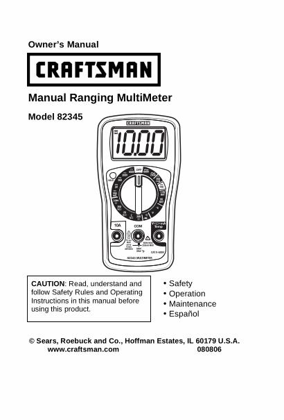
• Safety
• Operation
• Maintenance
• Español
Owner’s Manual
Manual Ranging MultiMeter
Model 82345
© Sears, Roebuck and Co., Hoffman Estates, IL 60179 U.S.A. www.craftsman.com 080806
CAUTION: Read, understand and follow Safety Rules and Operating
Instructions in this manual before using this product.
2
TABLE OF CONTENTS
Page
Warranty 3
Safety Instructions 4
Safety Symbols 5
Control and Jacks 6
Symbols and Annunciators 6
Specifications 7
Battery Installation 10
Operating Instructions 11
DC Voltage Measurements 11
AC Voltage Measurements 12
DC Current Measurements 13
Resistance Measurements 14
Temperature Measurements 14
Diode Test 15
Continuity Test 15
Battery Test 16
Data Hold 16
Maintenance 17
Replacing the Battery 18
Replacing the Fuse 18
Troubleshooting 19
Service and Parts 19
3
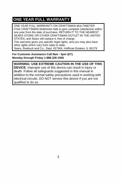
ONE YEAR FULL WARRANTY
ONE YEAR FULL WARRANTY ON CRAFTSMAN MULTIMETER If this CRAFTSMAN Multimeter fails to give complete satisfaction within one year from the date of purchase, RETURN IT TO THE NEAREST SEARS STORE OR OTHER CRAFTSMAN OUTLET IN THE UNITED STATES, and Sears will replace it, free of charge. This warranty gives you specific legal rights, and you may also have other rights which vary from state to state. Sears, Roebuck and Co., Dept. 817WA, Hoffman Estates, IL 60179
For Customer Assistance Call 9am - 5pm (ET)
Monday through Friday 1-888-326-1006
WARNING: USE EXTREME CAUTION IN THE USE OF THIS DEVICE. Improper use of this device can result in injury or death. Follow all safeguards suggested in this manual in
addition to the normal safety precautions used in working with electrical circuits. DO NOT service this device if you are not qualified to do so.
4
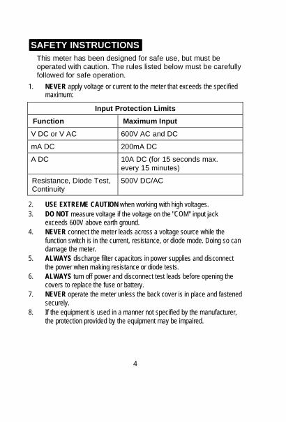
SAFETY INSTRUCTIONS
This meter has been designed for safe use, but must be operated with caution. The rules listed below must be carefully followed for safe operation.
1. NEVER apply voltage or current to the meter that exceeds the specified maximum:
Input Protection Limits
Function Maximum Input
V DC or V AC 600V AC and DC
mA DC 200mA DC
A DC 10A DC (for 15 seconds max.
every 15 minutes)
Resistance, Diode Test, Continuity
500V DC/AC
2. USE EXTREME CAUTION when working with high voltages.
3. DO NOT measure voltage if the voltage on the "COM" input jack exceeds 600V above earth ground.
4. NEVER connect the meter leads across a voltage source while the
function switch is in the current, resistance, or diode mode. Doing so can damage the meter.
5. ALWAYS discharge filter capacitors in power supplies and disconnect
the power when making resistance or diode tests.
6. ALWAYS turn off power and disconnect test leads before opening the covers to replace the fuse or battery.
7. NEVER operate the meter unless the back cover is in place and fastened
securely.
8. If the equipment is used in a manner not specified by the manufacturer,
the protection provided by the equipment may be impaired.
5
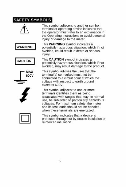
SAFETY SYMBOLS
This symbol adjacent to another symbol, terminal or operating device indicates that the operator must refer to an explanation in the Operating Instructions to avoid personal injury or damage to the meter.
This WARNING symbol indicates a potentially hazardous situation, which if not avoided, could result in death or serious injury.
This CAUTION symbol indicates a potentially hazardous situation, which if not avoided, may result damage to the product.
This symbol advises the user that the terminal(s) so marked must not be connected to a circuit point at which the voltage with respect to earth ground exceeds 600V.
This symbol adjacent to one or more terminals identifies them as being associated with ranges that may, in normal use, be subjected to particularly hazardous voltages. For maximum safety, the meter and its test leads should not be handled when these terminals are energized.
This symbol indicates that a device is protected throughout by double insulation or reinforced insulation.
WARNING
MAX 600V
CAUTION
6
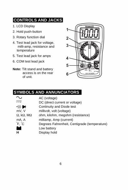
CONTROLS AND JACKS
1. LCD Display
2. Hold push-button
3. Rotary function dial
4. Test lead jack for voltage,
milli-amp, resistance and temperature
5. Test lead jack for amps
6. COM test lead jack
Note: Tilt stand and battery
access is on the rear
of unit.
SYMBOLS AND ANNUNCIATORS
AC (voltage)
DC (direct current or voltage)
•))) Continuity and Diode test
mV, V millivolt, volt (voltage)
, k , M ohm, kilohm, megohm (resistance)
mA, A milliamp, Amp (current) ºF,
ºC Degrees Fahrenheit, Centigrade (temperature)
º Low battery
H Display hold
1
2
3
4
5
6
7
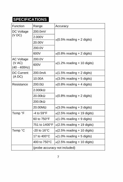
SPECIFICATIONS
Function Range Accuracy
200.0mV
2.000V
20.00V
200.0V
±(0.5% reading + 2 digits)
DC Voltage (V DC)
600V ±(0.8% reading + 2 digits)
200.0V AC Voltage
(V AC)
(40 - 400Hz) 600V
±(1.2% reading + 10 digits)
200.0mA ±(1.5% reading + 2 digits) DC Current
(A DC) 10.00A ±(3.0% reading + 5 digits)
200.0 ±(0.8% reading + 4 digits)
2.000k
20.00k
200.0k
±(0.8% reading + 2 digits)
Resistance
20.00M ±(3.0% reading + 3 digits)
-4 to 59°F ±(2.5% reading + 19 digits)
60 to 750°F ±(1.0% reading + 9 digits)
Temp °F
751 to 1400°F ±(2.5% reading + 19 digits)
-20 to 16°C ±(2.5% reading + 10 digits)
17 to 400°C ±(1.0% reading + 5 digits)
Temp °C
400 to 750°C ±(2.5% reading + 10 digits)
(probe accuracy not included)
8
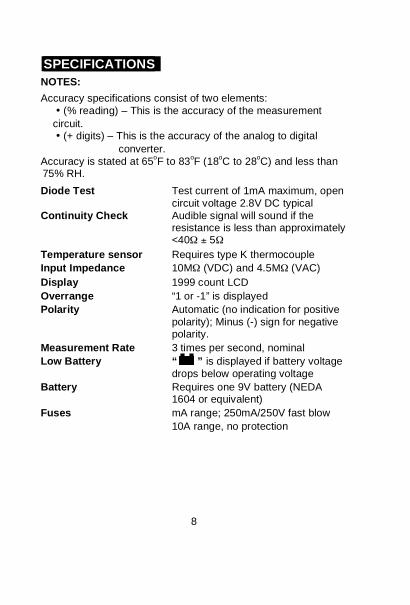
SPECIFICATIONS
NOTES:
Accuracy specifications consist of two elements:
• (% reading) – This is the accuracy of the measurement
circuit. • (+ digits) – This is the accuracy of the analog to digital
converter.
Accuracy is stated at 65oF to 83
oF (18
oC to 28
oC) and less than
75% RH.
Diode Test Test current of 1mA maximum, open
circuit voltage 2.8V DC typical
Continuity Check Audible signal will sound if the resistance is less than approximately <40 ± 5
Temperature sensor Requires type K thermocouple
Input Impedance 10M (VDC) and 4.5M (VAC)
Display 1999 count LCD
Overrange “1 or -1” is displayed
Polarity Automatic (no indication for positive
polarity); Minus (-) sign for negative polarity.
Measurement Rate 3 times per second, nominal
Low Battery “ ” is displayed if battery voltage
drops below operating voltage
Battery Requires one 9V battery (NEDA 1604 or equivalent)
Fuses mA range; 250mA/250V fast blow
10A range, no protection
9
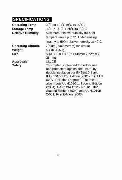
SPECIFICATIONS
Operating Temp 32oF to 104
oF (0
oC to 40
oC)
Storage Temp -4oF to 140
oF (-20
oC to 60
oC)
Relative Humidity Maximum relative humidity 80% for
temperatures up to 31°C decreasing
linearly to 50% relative humidity at 40°C.
Operating Altitude 7000ft (2000 meters) maximum.
Weight 5.4 oz. (153g).
Size 5.43” x 2.83” x 1.5” (138mm x 72mm x 38mm)
Approvals UL, CE
Safety This meter is intended for indoor use and protected, against the users, by
double insulation per EN61010-1 and IEC61010-1 2nd Edition (2001) to CAT II 600V; Pollution Degree 2. The meter
also meets UL 61010-1, Second Edition (2004), CAN/CSA C22.2 No. 61010-1, Second Edition (2004), and UL 61010B-2-031, First Edition (2003)
10
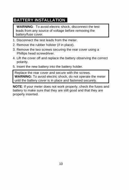
BATTERY INSTALLATION
WARNING: To avoid electric shock, disconnect the test
leads from any source of voltage before removing the battery/fuse cover.
1. Disconnect the test leads from the meter.
2. Remove the rubber holster (if in place).
3. Remove the two screws securing the rear cover using a Phillips head screwdriver.
4. Lift the cover off and replace the battery observing the correct polarity.
5. Insert the new battery into the battery holder.
Replace the rear cover and secure with the screws. WARNING: To avoid electric shock, do not operate the meter
until the battery cover is in place and fastened securely.
NOTE: If your meter does not work properly, check the fuses and battery to make sure that they are still good and that they are
properly inserted.
11
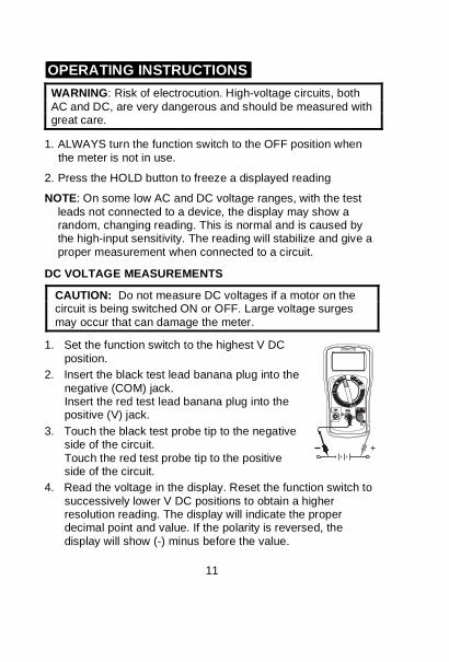
OPERATING INSTRUCTIONS
WARNING: Risk of electrocution. High-voltage circuits, both
AC and DC, are very dangerous and should be measured with great care.
1. ALWAYS turn the function switch to the OFF position when
the meter is not in use.
2. Press the HOLD button to freeze a displayed reading
NOTE: On some low AC and DC voltage ranges, with the test
leads not connected to a device, the display may show a random, changing reading. This is normal and is caused by the high-input sensitivity. The reading will stabilize and give a
proper measurement when connected to a circuit.
DC VOLTAGE MEASUREMENTS
CAUTION: Do not measure DC voltages if a motor on the circuit is being switched ON or OFF. Large voltage surges
may occur that can damage the meter.
1. Set the function switch to the highest V DC
position.
2. Insert the black test lead banana plug into the
negative (COM) jack. Insert the red test lead banana plug into the positive (V) jack.
3. Touch the black test probe tip to the negative side of the circuit.
Touch the red test probe tip to the positive side of the circuit.
4. Read the voltage in the display. Reset the function switch to
successively lower V DC positions to obtain a higher resolution reading. The display will indicate the proper decimal point and value. If the polarity is reversed, the
display will show (-) minus before the value.
12
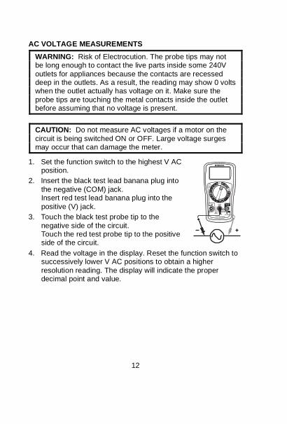
AC VOLTAGE MEASUREMENTS
WARNING: Risk of Electrocution. The probe tips may not be long enough to contact the live parts inside some 240V
outlets for appliances because the contacts are recessed deep in the outlets. As a result, the reading may show 0 volts when the outlet actually has voltage on it. Make sure the
probe tips are touching the metal contacts inside the outlet before assuming that no voltage is present.
CAUTION: Do not measure AC voltages if a motor on the
circuit is being switched ON or OFF. Large voltage surges may occur that can damage the meter.
1. Set the function switch to the highest V AC position.
2. Insert the black test lead banana plug into
the negative (COM) jack. Insert red test lead banana plug into the
positive (V) jack.
3. Touch the black test probe tip to the
negative side of the circuit. Touch the red test probe tip to the positive side of the circuit.
4. Read the voltage in the display. Reset the function switch to successively lower V AC positions to obtain a higher
resolution reading. The display will indicate the proper decimal point and value.
13
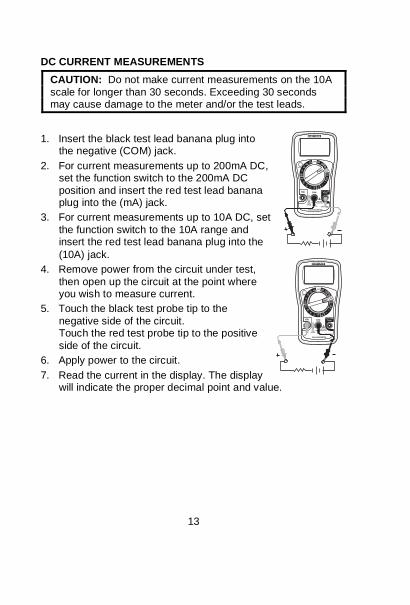
DC CURRENT MEASUREMENTS
CAUTION: Do not make current measurements on the 10A
scale for longer than 30 seconds. Exceeding 30 seconds may cause damage to the meter and/or the test leads.
1. Insert the black test lead banana plug into the negative (COM) jack.
2. For current measurements up to 200mA DC, set the function switch to the 200mA DC
position and insert the red test lead banana plug into the (mA) jack.
3. For current measurements up to 10A DC, set
the function switch to the 10A range and insert the red test lead banana plug into the
(10A) jack.
4. Remove power from the circuit under test,
then open up the circuit at the point where you wish to measure current.
5. Touch the black test probe tip to the
negative side of the circuit. Touch the red test probe tip to the positive
side of the circuit.
6. Apply power to the circuit.
7. Read the current in the display. The display will indicate the proper decimal point and value.
14
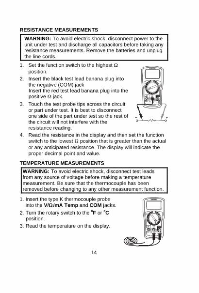
RESISTANCE MEASUREMENTS
WARNING: To avoid electric shock, disconnect power to the
unit under test and discharge all capacitors before taking any resistance measurements. Remove the batteries and unplug
the line cords.
1. Set the function switch to the highest
position.
2. Insert the black test lead banana plug into
the negative (COM) jack Insert the red test lead banana plug into the positive jack.
3. Touch the test probe tips across the circuit
or part under test. It is best to disconnect one side of the part under test so the rest of
the circuit will not interfere with the resistance reading.
4. Read the resistance in the display and then set the function
switch to the lowest position that is greater than the actual
or any anticipated resistance. The display will indicate the
proper decimal point and value.
TEMPERATURE MEASUREMENTS
WARNING: To avoid electric shock, disconnect test leads from any source of voltage before making a temperature
measurement. Be sure that the thermocouple has been removed before changing to any other measurement function.
1. Insert the type K thermocouple probe
into the V/ /mA Temp and COM jacks.
2. Turn the rotary switch to the oF or
oC
position.
3. Read the temperature on the display.
15
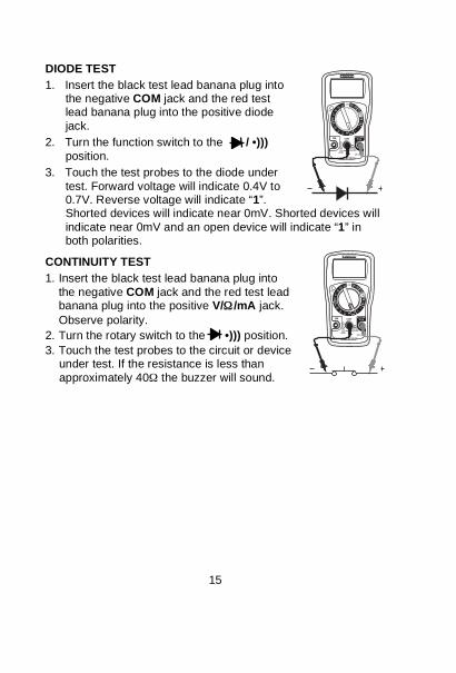
DIODE TEST
1. Insert the black test lead banana plug into the negative COM jack and the red test lead banana plug into the positive diode
jack.
2. Turn the function switch to the / •)))
position.
3. Touch the test probes to the diode under
test. Forward voltage will indicate 0.4V to 0.7V. Reverse voltage will indicate “1”. Shorted devices will indicate near 0mV. Shorted devices will
indicate near 0mV and an open device will indicate “1” in both polarities.
CONTINUITY TEST
1. Insert the black test lead banana plug into
the negative COM jack and the red test lead banana plug into the positive V/ /mA jack.
Observe polarity.
2. Turn the rotary switch to the •))) position.
3. Touch the test probes to the circuit or device under test. If the resistance is less than
approximately 40 the buzzer will sound.
16
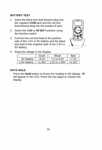
BATTERY TEST
1. Insert the black test lead banana plug into
the negative COM jack and the red test lead banana plug into the positive V jack.
2. Select the 1.5V or 9V BAT position using
the function switch.
3. Connect the red test lead to the positive side of the 1.5V or 9V battery and the black
test lead to the negative side of the 1.5V or 9V battery.
4. Read the voltage in the display.
Good Weak Bad
9V battery: >8.2V 7.2 to 8.2V <7.2V
1.5V battery: >1.35V 1.22 to 1.35V <1.22V
DATA HOLD
Press the Hold button to freeze the reading in the display. “H” will appear in the LCD. Press the key again to release the display.
17
MAINTENANCE
WARNING: To avoid electric shock, disconnect the test leads
from any source of voltage before removing the back cover or the battery or fuse cover.
WARNING: To avoid electric shock, do not operate your
meter until the battery and fuse cover are in place and fastened securely.
This MultiMeter is designed to provide years of dependable service, if the following care instructions are performed:
1. KEEP THE METER DRY. If it gets wet, wipe it off.
2. USE AND STORE THE METER IN NORMAL TEMPERATURES. Temperature extremes can shorten the life of the electronic parts and distort or melt plastic parts.
3. HANDLE THE METER GENTLY AND CAREFULLY. Dropping it can damage the electronic parts or the case.
4. KEEP THE METER CLEAN. Wipe the case occasionally
with a damp cloth. DO NOT use chemicals, cleaning solvents, or detergents.
5. USE ONLY FRESH BATTERIES OF THE RECOMMENDED
SIZE AND TYPE. Remove old or weak batteries so they do not leak and damage the unit.
6. IF THE METER IS TO BE STORED FOR A LONG PERIOD
OF TIME, the batteries should be removed to prevent damage to the unit.
18
REPLACING THE BATTERY
WARNING: To avoid electric shock, disconnect the test leads
from any source of voltage before removing the battery cover.
1. When the battery become exhausted or drop below the operating voltage, “ ” will appear in the lower left corner of the LCD display. The battery should be replaced.
2. Follow instructions for installing battery. See the Battery Installation section of this manual.
3. Dispose of the old batteries properly.
WARNING: To avoid electric shock, do not operate your
meter until the battery cover is in place and fastened securely.
REPLACING THE FUSE
WARNING: To avoid electric shock, disconnect the test leads from any source of voltage before removing the fuse cover.
1. Disconnect the test leads from the meter and any item under test.
2. Remove the protective rubber holster.
3. Remove the two screws securing the rear cover using a Phillips head screwdriver.
4. Remove the old fuse from its holder by gently pulling it out.
5. Install the new fuse into the holder.
6. Always use a fuse of the proper size and value (250mA/250V) fast blow.
7. Replace the rear cover and secure with the screws.
WARNING: To avoid electric shock, do not operate your
meter until the fuse cover is in place and fastened securely.
UL LISTED The UL mark does not indicate that this product has been
evaluated for the accuracy of its readings.
19
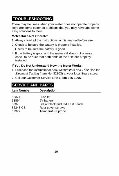
TROUBLESHOOTING
There may be times when your meter does not operate properly. Here are some common problems that you may have and some easy solutions to them.
Meter Does Not Operate:
1. Always read all the instructions in this manual before use.
2. Check to be sure the battery is properly installed.
3. Check to be sure the battery is good.
4. If the battery is good and the meter still does not operate,
check to be sure that both ends of the fuse are properly installed.
If You Do Not Understand How the Meter Works:
1. Purchase the instructional book Multitesters and Their Use for Electrical Testing (Item No. 82303) at your local Sears store.
2. Call our Customer Service Line 1-888-326-1006.
SERVICE AND PARTS
Item Number Description
82374 Fuse kit 93894 9V battery
82378 Set of black and red Test Leads 82345-CS Rear cover screws 82377 Temperature probe