Embed Size (px)
Citation preview
1
Phone
Manual
Model GF Digital Glycol Feeder
InstallationMaintenanceRepairManual
Advantage Controls4700 Harold Abitz Dr.Muskogee, OK 74403Phone: 800-743-7431Fax: 888-686-6212www.advantagecontrols.com 04/2020

2
Table of Contents
I. Introduction .................................................................................................2 II. ModelNumberingandGeneralSpecifications............................................3 III. Installation ...................................................................................................4 Electrical Wiring ...............................................................................4 Mounting Instructions .......................................................................4 Typical Installation and Measurements ............................................5 Start Up and Test Procedure / Recommendations ...........................6 IV. Digital Front Panel Description ...................................................................7 V. Digital System Operation Overview ............................................................8 Description of Set Up Menu Screens ...............................................8 Calibration ........................................................................................9 Pressure Set ..................................................................................10 Clock Set ........................................................................................ 11 System Set .....................................................................................12 Diagnostics .....................................................................................13 Level Set ........................................................................................14 VI. Parts List ...................................................................................................15 VII. Digital Controller Wiring ............................................................................18 VIII. Troubleshooting and Maintenance ............................................................19 IX. Warranty ...................................................................................................21
Reference Chart % Propylene Glycol .............................................................................22Reference Chart % Ethylene Glycol ...............................................................................22
I. Introduction
The Advantage Controls Glycol Feed Systems are design to regulate pressure in closed loop Hydronic Heating and Cooling applications.
Advantage Controls micro-processor base controller reads a solid state pressure transducer, displays system pressure, and uses a 16 character keyboard for the entry of control parameters. The micro-processor has built in real-time clock and EEPROM back-up for all user settings, in case of power interruptions. Setting for all functions are made using the keyboard, readings are displayed on a back lit 16 character alphanumeric display.
Advantage Controls Glycol Feeders are stand alone pre-wired, pre-plumbed systems designed for ease of installation. Our systems are mounted on a powder coated steel frame with anchor points.
AdvantageControlsModelDesignationallowsforawidevarietyofconfigurations,operationandfunctionofeachGlycolFeedSystemsthisisdependentonyourspecificmodelnumber.Pleasecheckyourmodel number against the selection guide for better understanding of your system.
Please read this instruction manual to become familiar with your system.
3
II. ModelNumberingandGeneralSpecifications
BUILD A MODEL GF - __ __ __ __ __ __ - __ __
TANK SELECTION0 = No tank1 = 55 gallon poly2 = 100 gallon poly3 = 30 gallon poly7 = 150 gallon poly
STAND SELECTIONA = Powder Coated steel stand B = Powder Coated steel stand w/ mixer bracketC = Tank top mount (no tank included) D = Portable stand with built in rollers
PUMP SELECTION* Dual pump sys. require 2 pump selections (i.e., -11)0 = No pump 1 = 1.5gpmat100PSI;1/3hp2 = 3.75gpmat100PSI;1/2hp3 = 6.1gpmat60PSI;3/4hp4 = 9.9 gpm at 60 PSI; 1.5 hp5 = 30 gpd at 100 PSI; solenoid driven
PUMP CONFIGURATIONA = StandardconfigurationB = Alternating pumps for single loops
(requires 2 pump selections)C = Pump plumbed for transfer duty into tank
LOOP SELECTION * Dual loop sys. require 2 loop selections (i.e., -11)0 = No loop1 = Sch 80 PVC loop; 100 PSI max; 100°F max2 = Copper/brass loop; 100 PSI max; 180°F max3 = Carbon steel loop; 100 PSI max
CONTROL SELECTIONA = Digital controller w/ 0-100 PSI pressure transducer for 30 gal & + sizesD = Pressure transducer, level wand and pump
starter relay for use with separately ordered MegaTron or XS with 4-20mA input ability
F = Digital controller for dual loops with two sensors
OPTIONS1 = 240V (not available with pump option 1)2 = 4-20mA output of pressure on digital controller3 = Solenoid valve for pressure relief on digital units4 = 30-50 PSI pressure switch for analog units5 = Position backcheck to use tank for expansionH = 1/4” PVC pipe instead of pump suction tubingM = Mixer controls (order mixer separate)Y = ETL approval (only on units with controller option D)
Most units include poly tank and stand, low level switch with audible alarm (100db) with silence switch, dry contact alarm, pressure relief valve and plumbing assembly with pressure gauge.
Digital models display the actual loop pressure and allow for user settable control points from a pressure sensor rated for 5-100 psi (0.3-6.9 bar). 16 character LCD, backlit display. EPROM memory.
4
III. Installation
Electrical Wiring
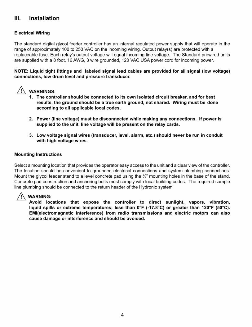
The standard digital glycol feeder controller has an internal regulated power supply that will operate in the range of approximately 100 to 250 VAC on the incoming wiring. Output relay(s) are protected with a replaceable fuse. Each relay’s output voltage will equal incoming line voltage. The Standard prewired units are supplied with a 8 foot, 16 AWG, 3 wire grounded, 120 VAC USA power cord for incoming power.
NOTE:Liquidtightfittingsandlabeledsignalleadcablesareprovidedforallsignal(lowvoltage)connections,lowdrumlevelandpressuretransducer.
WARNINGS: 1. Thecontrollershouldbeconnectedtoitsownisolatedcircuitbreaker,andforbest
results, the ground should be a true earth ground, not shared. Wiring must be done according to all applicable local codes.
2. Power(linevoltage)mustbedisconnectedwhilemakinganyconnections.Ifpowerissuppliedtotheunit,linevoltagewillbepresentontherelaycards.
3. Lowvoltagesignalwires(transducer,level,alarm,etc.)shouldneverberuninconduitwithhighvoltagewires.
Mounting Instructions
Select a mounting location that provides the operator easy access to the unit and a clear view of the controller. The location should be convenient to grounded electrical connections and system plumbing connections. Mount the glycol feeder stand to a level concrete pad using the ½” mounting holes in the base of the stand. Concrete pad construction and anchoring bolts must comply with local building codes. The required sample line plumbing should be connected to the return header of the Hydronic system
WARNING:Avoid locations that expose the controller to direct sunlight, vapors, vibration, liquid spills or extreme temperatures; less than 0°F (-17.8°C) or greater than 120°F (50°C).EMI(electromagnetic interference) from radio transmissions and electric motors can alsocausedamageorinterferenceandshouldbeavoided.
!
!
5
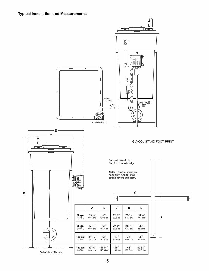
Typical Installation and Measurements
SystemConnection
Circulation Pump
B
AE
Side View Shown
1/4” bolt hole drilled 3/4” from outside edge
Note: This is for mountingholes only. Controller will extend beyond this depth.
GLYCOL STAND FOOT PRINT
C
D
A B C D E
30gal113.5L
23 ¾”60.3 cm
51”129.5 cm
27 ½”69.8 cm
25 ½”64.7 cm
30 ½”77.4 cm
55gal208.1L
27 ½”69.8 cm
65”165.1 cm
27 ½”69.8 cm
25 ½”64.7 cm
32”81.2 cm
100gal378.5L
31 ¼”79.3 cm
66”167.6 cm
37”93.9 cm
35”88.9 cm
38”96.5 cm
150gal567.8L
373/8”94.6 cm
565/16”143.04 cm
45”114.3 cm
43”109.2 cm
495/16”125.3 cm
6
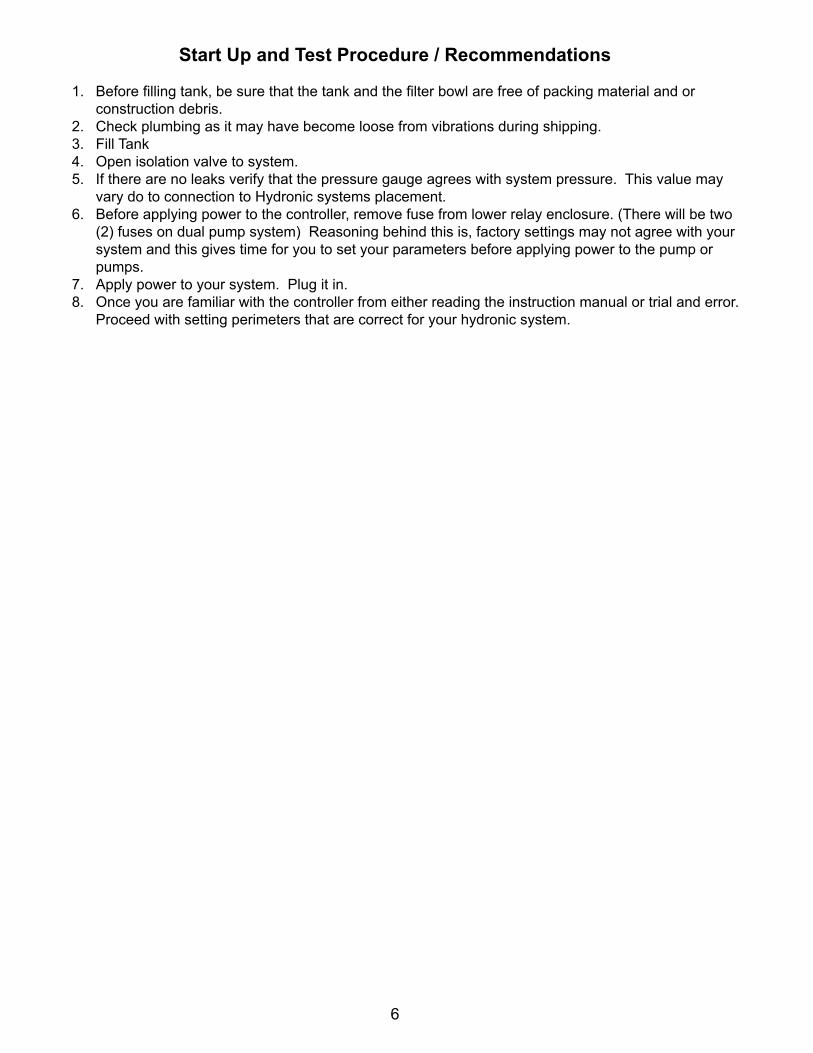
Start Up and Test Procedure / Recommendations
1. Beforefillingtank,besurethatthetankandthefilterbowlarefreeofpackingmaterialandorconstruction debris.
2. Check plumbing as it may have become loose from vibrations during shipping.3. Fill Tank 4. Open isolation valve to system.5. If there are no leaks verify that the pressure gauge agrees with system pressure. This value may
vary do to connection to Hydronic systems placement.6. Before applying power to the controller, remove fuse from lower relay enclosure. (There will be two
(2) fuses on dual pump system) Reasoning behind this is, factory settings may not agree with your system and this gives time for you to set your parameters before applying power to the pump or pumps.
7. Apply power to your system. Plug it in. 8. Once you are familiar with the controller from either reading the instruction manual or trial and error.
Proceed with setting perimeters that are correct for your hydronic system.

7
DigitalFrontPanelDrawing
IV. Digital Front Panel Description
READ: 1x16 (1/4”) Alpha Numeric Display.
CONTROL: Relay 1, Relay 2 - HOA switches for control relays.
SETUP/RUNkey - System initializes into RUN mode. Press this switch to toggle the controller from SET UP mode to RUN mode.
UP/DOWNarrows - Used to change the display from one line to the next. All menus are circular, so when all items in a menu have been displayed, the display will return to the originally displayed item.
ENTERkey - Used to access a menu and to log a changed value into the program. CLEARkey - Used to clear numerical values from items being changed in the SET UP mode.
DECIMALkey - Used at certain places to change a function or displayed items. For example, when temperature is being displayed, pressing the DECIMAL key will change the reading from Fahrenheit to Celsius or visa versa.
NUMERICALkeys - Used to enter new values in the SET UP mode.
ENTER
CLEAR
•
1
SET UPRUN
8
V. DigitalSystemOperationOverview
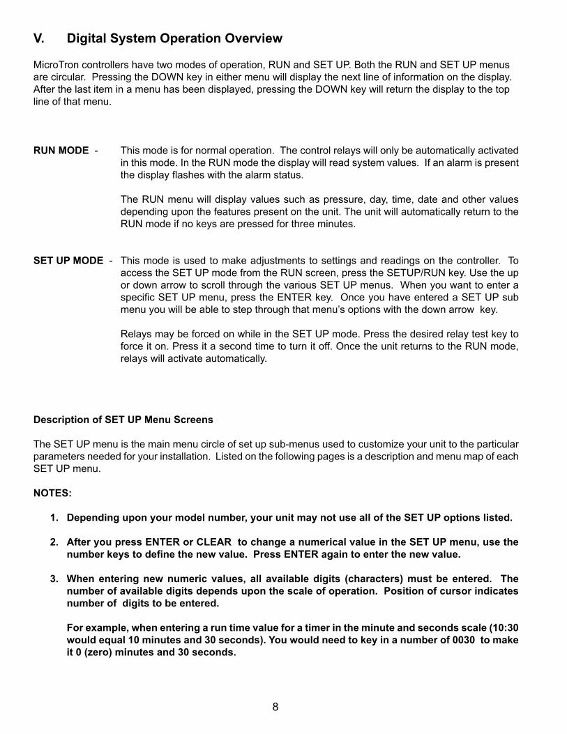
MicroTron controllers have two modes of operation, RUN and SET UP. Both the RUN and SET UP menus are circular. Pressing the DOWN key in either menu will display the next line of information on the display. After the last item in a menu has been displayed, pressing the DOWN key will return the display to the top line of that menu.
RUN MODE - This mode is for normal operation. The control relays will only be automatically activated in this mode. In the RUN mode the display will read system values. If an alarm is present thedisplayflasheswiththealarmstatus.
The RUN menu will display values such as pressure, day, time, date and other values depending upon the features present on the unit. The unit will automatically return to the RUN mode if no keys are pressed for three minutes.
SET UP MODE - This mode is used to make adjustments to settings and readings on the controller. To access the SET UP mode from the RUN screen, press the SETUP/RUN key. Use the up or down arrow to scroll through the various SET UP menus. When you want to enter a specificSETUPmenu,presstheENTERkey.OnceyouhaveenteredaSETUPsubmenu you will be able to step through that menu’s options with the down arrow key.
Relays may be forced on while in the SET UP mode. Press the desired relay test key to forceiton.Pressitasecondtimetoturnitoff.OncetheunitreturnstotheRUNmode,relays will activate automatically.
Description of SET UP Menu Screens
The SET UP menu is the main menu circle of set up sub-menus used to customize your unit to the particular parameters needed for your installation. Listed on the following pages is a description and menu map of each SET UP menu.
NOTES:
1. Depending upon your model number, your unit may not use all of the SET UP options listed.
2. AfteryoupressENTERorCLEARtochangeanumericalvalueintheSETUPmenu,usethenumberkeystodefinethenewvalue.PressENTERagaintoenterthenewvalue.
3. Whenenteringnewnumeric values, all availabledigits (characters)mustbeentered. Thenumberofavailabledigitsdependsuponthescaleofoperation.Positionofcursorindicatesnumber of digits to be entered.
Forexample,whenenteringaruntimevalueforatimerintheminuteandsecondsscale(10:30wouldequal10minutesand30seconds).Youwouldneedtokeyinanumberof0030tomakeit0(zero)minutesand30seconds.
9
-- CALIBRATION --
CALIBRATE XXX psi (DAGF-2 systems have additional options. Continue cycling down for each system.)
To change pressure reading
To accept value keyed in using number keys
CAL. FACTOR (Read only for diagnostics)
Return to CALIBRATION screen
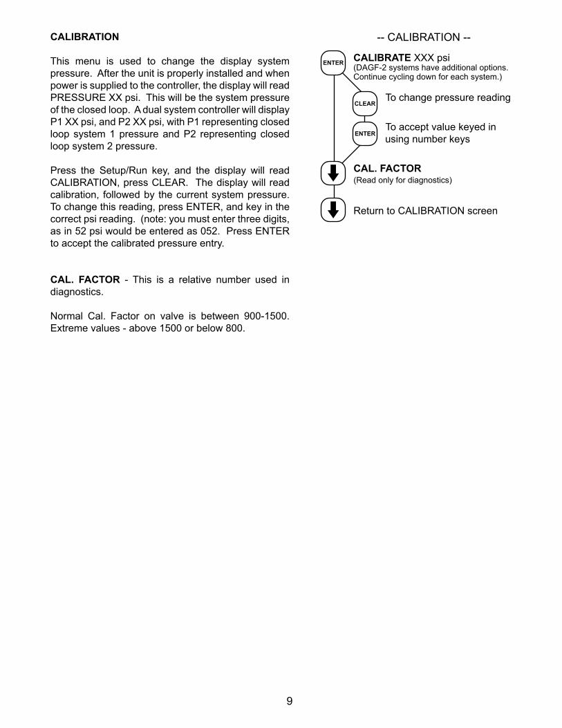
CALIBRATION
This menu is used to change the display system pressure. After the unit is properly installed and when power is supplied to the controller, the display will read PRESSURE XX psi. This will be the system pressure of the closed loop. A dual system controller will display P1 XX psi, and P2 XX psi, with P1 representing closed loop system 1 pressure and P2 representing closed loop system 2 pressure.
Press the Setup/Run key, and the display will read CALIBRATION, press CLEAR. The display will read calibration, followed by the current system pressure. To change this reading, press ENTER, and key in the correct psi reading. (note: you must enter three digits, as in 52 psi would be entered as 052. Press ENTER to accept the calibrated pressure entry.
CAL. FACTOR - This is a relative number used in diagnostics.
Normal Cal. Factor on valve is between 900-1500. Extreme values - above 1500 or below 800.
CLEAR
ENTER
ENTER
10
-- PRESSURE SET (1 & 2) --CUT-INXXX psi (DAGF-2 systems have two separate PRESSURE SET menus.)
To change cut-in pressure
To accept value keyed in using number keys
CUT-OUT XXX psi
To change cut-out pressure
To accept value keyed in using number keys
RELIEF TRIP (Set to “0” to disable)
To change high alarm setting
To accept value keyed in using number keys
RELIEF DIFF XXX psi
Tochangereliefdiffpressure
To accept value keyed in using number keys
LIMIT TIME H:MM (Set to “0” to disable)
To change limit time
To accept value keyed in using number keys
RELAYDELAY :SS (Set to “0” to disable)
To change relay delay
To accept value keyed in using number keys
Return to PRESSURE SET screen
CLEAR
ENTER
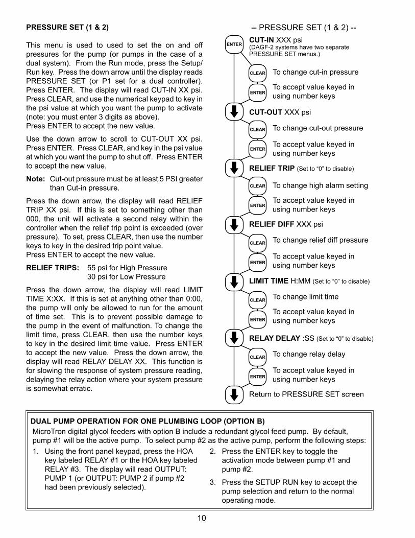
PRESSURESET(1&2)
This menu is used to used to set the on and offpressures for the pump (or pumps in the case of a dual system). From the Run mode, press the Setup/Run key. Press the down arrow until the display reads PRESSURE SET (or P1 set for a dual controller). Press ENTER. The display will read CUT-IN XX psi. Press CLEAR, and use the numerical keypad to key in the psi value at which you want the pump to activate (note: you must enter 3 digits as above). Press ENTER to accept the new value.
Use the down arrow to scroll to CUT-OUT XX psi. Press ENTER. Press CLEAR, and key in the psi value atwhichyouwantthepumptoshutoff.PressENTERto accept the new value.
Note: Cut-out pressure must be at least 5 PSI greater than Cut-in pressure.
Press the down arrow, the display will read RELIEF TRIP XX psi. If this is set to something other than 000, the unit will activate a second relay within the controller when the relief trip point is exceeded (over pressure). To set, press CLEAR, then use the number keys to key in the desired trip point value. Press ENTER to accept the new value.
RELIEF TRIPS: 55 psi for High Pressure 30 psi for Low Pressure
Press the down arrow, the display will read LIMIT TIME X:XX. If this is set at anything other than 0:00, the pump will only be allowed to run for the amount of time set. This is to prevent possible damage to the pump in the event of malfunction. To change the limit time, press CLEAR, then use the number keys to key in the desired limit time value. Press ENTER to accept the new value. Press the down arrow, the display will read RELAY DELAY XX. This function is for slowing the response of system pressure reading, delaying the relay action where your system pressure is somewhat erratic.
ENTER
CLEAR
ENTER
DUALPUMPOPERATIONFORONEPLUMBINGLOOP(OPTIONB)MicroTron digital glycol feeders with option B include a redundant glycol feed pump. By default, pump #1 will be the active pump. To select pump #2 as the active pump, perform the following steps:1. Using the front panel keypad, press the HOA
key labeled RELAY #1 or the HOA key labeled RELAY #3. The display will read OUTPUT: PUMP 1 (or OUTPUT: PUMP 2 if pump #2 had been previously selected).
2. Press the ENTER key to toggle the activation mode between pump #1 and pump #2.
3. Press the SETUP RUN key to accept the pump selection and return to the normal operating mode.
CLEAR
ENTER
CLEAR
ENTER
CLEAR
ENTER
CLEAR
ENTER

11
-- CLOCK SET --
SET TIME XX.XX (HH.MM)
To change time
To accept value keyed in using number keys
SET DATE XX.XX.XXXX (MM.DD.YYYY)
To change date
To accept value keyed in using number keys
SETDAY (Sunday-Saturday)
To change day
To cycle through day options
To set day
Return to CLOCK SET screen
CLOCK SET
This menu is for adjusting the time, date and day of the week.
After entering a new value, hit the ENTER key to accept the value and advance.
The clock time is based on a 24 hour clock. So, a time of 1:00 pm would be shown as 13.00.
NOTES: Ifunitdoesn’thaveabiocidetimer,there willnotbeaSETDAYselection.
ENTER
CLEAR
ENTER
CLEAR
ENTER
ENTER
ENTER
12
-- SYSTEM SET --
PASSWORD XXXX
To change password
To accept value keyed in using number keys
PROPORTIONAL OUT
STRAIGHT OUT
ZERO IN XXX psi (Read only for diagnostics. DAGF-2 systems have additional options. Continue cycling down for each system.)
UNITS: PSI
UNITS: BAR
Return to SYSTEM SET screen
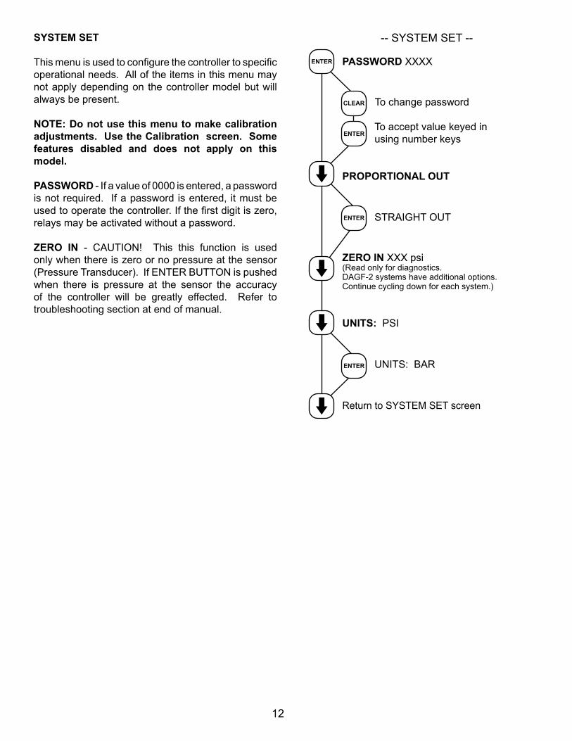
SYSTEMSET
Thismenuisusedtoconfigurethecontrollertospecificoperational needs. All of the items in this menu may not apply depending on the controller model but will always be present.
NOTE:Donotusethismenutomakecalibrationadjustments. Use the Calibration screen. Some features disabled and does not apply on this model.
PASSWORD - If a value of 0000 is entered, a password is not required. If a password is entered, it must be usedtooperatethecontroller.Ifthefirstdigitiszero,relays may be activated without a password.
ZERO IN - CAUTION! This this function is used only when there is zero or no pressure at the sensor (Pressure Transducer). If ENTER BUTTON is pushed when there is pressure at the sensor the accuracy of the controller will be greatly effected. Refer totroubleshooting section at end of manual.
ENTER
CLEAR
ENTER
ENTER
ENTER

13
-- DIAGNOSTICS --
MODEL # DAGF
FIRMWAREV.(n)
TESTDISPLAY
Displaywillflash(allspacesshould light)pressENTERagaintofinish test
TESTKEYPAD
Key on keypad pressed, corresponding number appears on display, ENTER to quit
RESET CALIBRATE
If pressed resets calibrations to factory default
MAX PSI: XXX
Press CLEAR to change pressure scale
Use numerical keys and then press ENTER to accept
OUTPUT Pump 1 (Only on DAGF-1 systems.)
Toggles between pumps
Return to DIAGNOSTICS screen
ENTER
DIAGNOSTICS
This menu is used to select, enter and test the following items.
MODEL NUMBER - Read only screen.
FIRMWARE VERSION NUMBER - Read only screen. Have both available for service
TESTDISPLAY - Press ENTER and all pixels will flash.Makeavisualchecktoseethatallpixelsarelit.
TEST KEYPAD - Press ENTER, then press each individual key to test its function. NOTE: Pressing the SET UP/RUN key returns display to the main menu. Pressing ENTER again returns to TEST KEYPAD.
RESET CALIBRATE - CAUTION! Pressing ENTER Button here will reset calibration data to factory defaults. You will need to reset or verify all setting after doing this.
MAX PSI: XXX - This allows you to set the maximum psi. The max setting should correspond to the max pressure rating of the transducer. On the standard model, this is 100 psi. This setting allows the controller to be used with pressure transducers with “other” output ranges. Press CLEAR to change the pressure scale. Use numerical keys and then press ENTER to accept.
OUTPUT Pump 1 (DAGF-1 models only) This is used in conjunction with feeders with Option B, dual pump system. This allows the operator to switch from pump one to pump two when option E is specified.
ENTER
ENTER
ENTER
CLEAR
ENTER
14
-- LEVEL SET --
LEVEL ONE ENABLED
LEVEL ONE DISABLED
LEVEL ONE: NO PUMP
LEVEL ONE: PUMP OK
LEVEL TWO ENABLED
LEVEL TWO DISABLED
LEVEL TWO: NO PUMP
LEVEL TWO: PUMP OK
LEVEL THREE ENABLED
LEVEL THREE DISABLED
LEVEL THREE: NO PUMP
LEVEL THREE: PUMP OK
LEVEL FOUR ENABLED
LEVEL FOUR DISABLED
LEVEL FOUR: NO PUMP
LEVEL FOUR: PUMP OK
Return to LEVEL SET screen
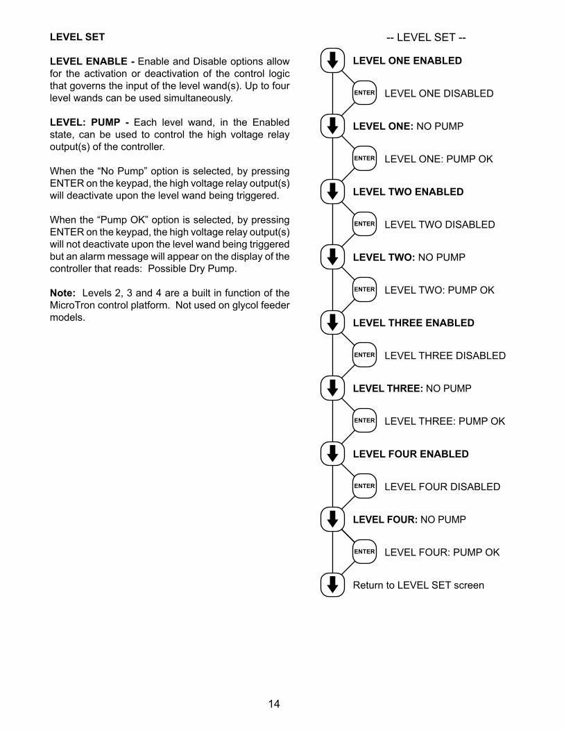
LEVEL SET
LEVELENABLE-Enable and Disable options allow for the activation or deactivation of the control logic that governs the input of the level wand(s). Up to four level wands can be used simultaneously.
LEVEL: PUMP - Each level wand, in the Enabled state, can be used to control the high voltage relay output(s) of the controller.
When the “No Pump” option is selected, by pressing ENTER on the keypad, the high voltage relay output(s) will deactivate upon the level wand being triggered.
When the “Pump OK” option is selected, by pressing ENTER on the keypad, the high voltage relay output(s) will not deactivate upon the level wand being triggered but an alarm message will appear on the display of the controller that reads: Possible Dry Pump.
Note: Levels 2, 3 and 4 are a built in function of the MicroTron control platform. Not used on glycol feeder models.
ENTER
ENTER
ENTER
ENTER
ENTER
ENTER
ENTER
ENTER
15
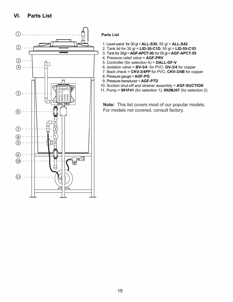
VI. Parts List
Parts List
1. Level wand for 30 gl = ALL-S30; 55 gl = ALL-S42 2. Tank lid for 30 gl = LID-30-C1D; 55 gl = LID-55-C1D 3. Tank for 30gl = AGF-APCT-30; for 55 gl = AGF-APCT-55 4. Pressure relief valve = AGF-PRV 5. Controller (for selection A) = DALL-GF-V 6. Isolation valve = BV-3/4 for PVC; GV-3/4 for copper 7. Back check = CKV-3/4PP for PVC; CKV-3/4B for copper 8. Pressure gauge = AGF-PG 9. Pressure transducer = AGF-PTD 10. Suction shut-off and strainer assembly = AGF-SUCTION11. Pump = 991F41 (for selection 1); 992MJ07 (for selection 2)
1
2
3
4
5
6
7
8
11
10
6
9
Note: This list covers most of our popular models.For models not covered, consult factory.
16
17
Note: Dual Digital Glycol Feeders utilize one controller monitoring two separate pressures sensors. The menu will have additional selections for each function. Both pressure readings will be displayed in the Run screen: "P1: 060 P2045 psi".
DualDigitalGlycolFeeder(WCD-370302)
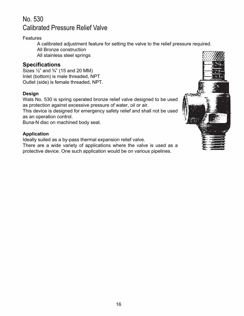
No. 530Calibrated Pressure Relief ValveFeatures A calibrated adjustment feature for setting the valve to the relief pressure required. All Bronze construction All stainless steel springs
SpecificationsSizes ½” and ¾” (15 and 20 MM)Inlet (bottom) is male threaded, NPTOutlet (side) is female threaded, NPT.
DesignWats No. 530 is spring operated bronze relief valve designed to be used as protection against excessive pressure of water, oil or air.This device is designed for emergency safety relief and shall not be used as an operation control.Buna-N disc on machined body seat.
ApplicationIdeally suited as a by-pass thermal expansion relief valve.There are a wide variety of applications where the valve is used as a protective device. One such application would be on various pipelines.
1719
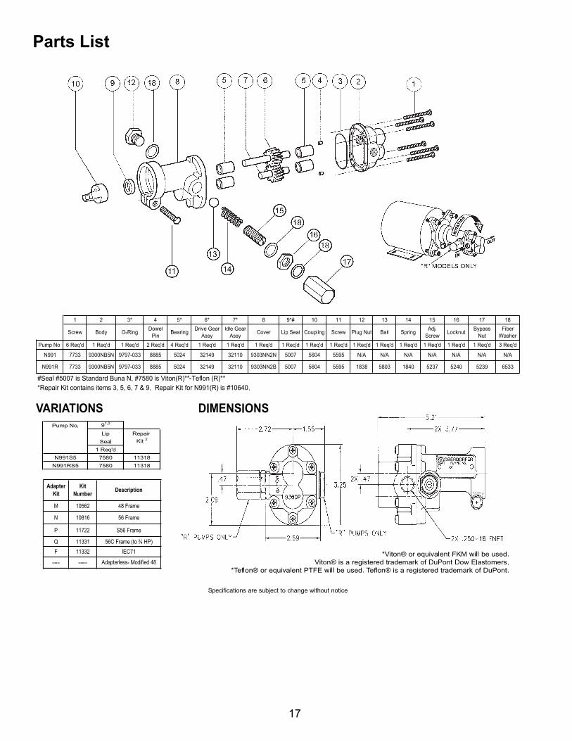
Parts List

18
VII. Digital Controller Wiring
REDBLK
B W
R COM
B N.O.N.C.
R W WG B
WG B
R W WG B
WG
B
B W
R COM
B N.O.N.C.
R W WG B
WG
B
B W
R COM
B N.O.N.C.
(Pump #1)
(Pump #2)
(Controller)
(Controller)
Pressure SensorDual Loop or Single Loop with 2 pumps - Fuse BoxSingle Loop - Fuse Box
Conduit Layout for LCD Display
2 1
10 9
Low LevelWand
PressureSensor
RelayRibbonCable
Power
ScreenContrast
Low LevelWand 2
(dual unit model)
PressureSensor 2
(dual unit model)
Red
Black
Red
Black
Black
Red
Black
Red
Pump 1
POWER SUPPLY
Relay / Power Card (REV D)
Green (-12)
White (+5)Red (+12)
Black (Gnd)
FUSEFUSE
FUSE
FUS
E
FUSE
1
2 4
N.O N.C NET GRD
N.O N.C NET GRD
N.O N.C NET GRD N.O N.C NET GRD
N.O N.C NET GRD
H N G
POWER INPUTRibbon Cable1
2
9
10
Solenoid(on single
pump)
Pump 2(on dual pump)
Solenoid #1on dualpump
Solenoid #2on dualpump
Dry Contact
54321
Logic Board Relay / Power Board
19
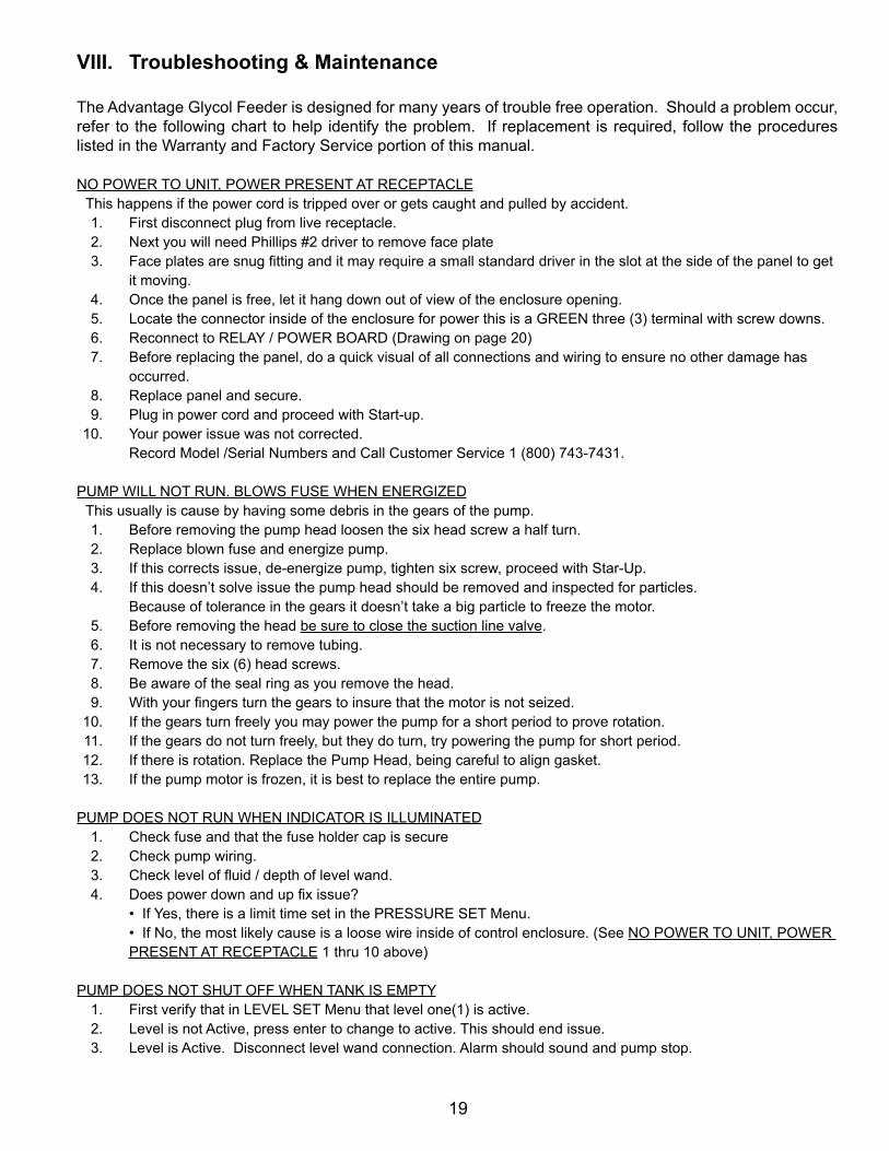
VIII. Troubleshooting&Maintenance
The Advantage Glycol Feeder is designed for many years of trouble free operation. Should a problem occur, refer to the following chart to help identify the problem. If replacement is required, follow the procedures listed in the Warranty and Factory Service portion of this manual.
NO POWER TO UNIT, POWER PRESENT AT RECEPTACLEThis happens if the power cord is tripped over or gets caught and pulled by accident.
1. First disconnect plug from live receptacle. 2. Next you will need Phillips #2 driver to remove face plate 3. Faceplatesaresnugfittinganditmayrequireasmallstandarddriverintheslotatthesideofthepaneltoget
it moving. 4. Once the panel is free, let it hang down out of view of the enclosure opening. 5. Locate the connector inside of the enclosure for power this is a GREEN three (3) terminal with screw downs. 6. Reconnect to RELAY / POWER BOARD (Drawing on page 20) 7. Before replacing the panel, do a quick visual of all connections and wiring to ensure no other damage has
occurred. 8. Replace panel and secure. 9. Plug in power cord and proceed with Start-up. 10. Your power issue was not corrected.
Record Model /Serial Numbers and Call Customer Service 1 (800) 743-7431.
PUMP WILL NOT RUN. BLOWS FUSE WHEN ENERGIZEDThis usually is cause by having some debris in the gears of the pump.
1. Before removing the pump head loosen the six head screw a half turn. 2. Replace blown fuse and energize pump. 3. If this corrects issue, de-energize pump, tighten six screw, proceed with Star-Up. 4. If this doesn’t solve issue the pump head should be removed and inspected for particles.
Because of tolerance in the gears it doesn’t take a big particle to freeze the motor. 5. Before removing the head be sure to close the suction line valve. 6. It is not necessary to remove tubing. 7. Remove the six (6) head screws. 8. Be aware of the seal ring as you remove the head. 9. Withyourfingersturnthegearstoinsurethatthemotorisnotseized. 10. If the gears turn freely you may power the pump for a short period to prove rotation. 11. If the gears do not turn freely, but they do turn, try powering the pump for short period. 12. If there is rotation. Replace the Pump Head, being careful to align gasket. 13. If the pump motor is frozen, it is best to replace the entire pump.
PUMP DOES NOT RUN WHEN INDICATOR IS ILLUMINATED 1. Check fuse and that the fuse holder cap is secure 2. Check pump wiring. 3. Checkleveloffluid/depthoflevelwand. 4. Doespowerdownandupfixissue? • If Yes, there is a limit time set in the PRESSURE SET Menu. • If No, the most likely cause is a loose wire inside of control enclosure. (See NO POWER TO UNIT, POWER
PRESENT AT RECEPTACLE 1 thru 10 above)
PUMP DOES NOT SHUT OFF WHEN TANK IS EMPTY 1. First verify that in LEVEL SET Menu that level one(1) is active. 2. Level is not Active, press enter to change to active. This should end issue. 3. Level is Active. Disconnect level wand connection. Alarm should sound and pump stop.

20
•IfYes,inspectendoflevelwandfordebrisordamage,replaceifneeded.(Thefloatatbottomofthewandshould have free movement, up and down.
• If No, inspect wire for damage. If no damage visible inspect internal wiring. (See NO POWER TO UNIT, POWER PRESENT AT RECEPTACLE 1 thru 10 above)
4. If no resolution is found, record Serial / Model numbers and call customer service
LOW LEVEL ALARM STAYS ON 1. Disconnect level wand connection and short across connectors with screw driver. (this is low voltage and not
dangerous) 2. Thisturnsoffthealarm.Thereisaproblemwiththewanditself. 3. Inspectthefloatendofthelevelwand. 4. Ifthefloatisfreemovingreplacewand. 5. Shortingtheconnecterdoesnotturnoffalarm.Inspectinternalwiring.(SeeNO POWER TO UNIT, POWER
PRESENT AT RECEPTACLE 1 thru 10 above) 6. Still no resolution record Model / Serial numbers and call customer service.
READING ZERO WILL NOT CALIBRATE1. Isolate glycol feeder from system pressure by closing isolation valve. 2. Release pressure at the sensor by either valve or loosening union.3. With pressure at zero press ENTER.4. Controller will than display CALIBRATE.5. Open Isolation Valve to reestablish pressure to Sensor.6. Press enter and key in correct pressure. 7. Press enter key and the correct value should display after brief moment.
Maintenance
Maintenance and care will depend upon the usage and environment in which the system is subjected to. The following is the suggested regular maintenance required to keep the glycol feed system operating properly:
TANK AND PLUMBINGPeriodically check the piping and tubing to insure proper discharge of the glycol solution. The strainer should be periodically checked for clogging and wear. The level wand should be removed and cleaned to prevent clogging.
GEAR PUMPCheck for proper operation. If any pump/motor noises, leaks or changes in operation are detected, the pumpshouldberemovedandexaminedbyacertifiedtechnician.Gearpumprepairscanbedifficultandshouldonlybeattemptedbyqualifiedpersonnel.Improperrepairsorassemblycanresultinpumpfailureandnullificationofthewarranty.Nolubricationisrequired.
PRESSURE RELIEF VALVEPeriodic checking and replacement of the adjustment seal is the only maintenance required.
21
IX. Manufacturer’s Product Warranty
Advantage Controls warrants units of its manufacture to be free of defects in material or workmanship. Liability under this policy extends for 12 months from date of installation for all aspects of the glycol feeder with the controller only covered for an additional 12 months. Liability is limited to repair or replacement of any failed equipment or part proven defective in material or workmanship upon manufacturer’s examination. Removal and installation costs are not included under this warranty. Manufacturer’s liability shall never exceed the selling price of equipment or part in question. Advantage disclaims all liability for damage caused by its products by improper installation, maintenance, use or attempts to operate products beyond their intended functionality, intentionally or otherwise, or any unauthorized repair. Advantage is not responsible for damages, injuries or expense incurred through the use of its products.
The above warranty is in lieu of other warranties, either expressed or implied. No agent of ours is authorized to provide any warranty other than the above.
30DayBillingMemoPolicy Advantage Controls maintains a unique factory exchange program to ensure uninterrupted service with minimum downtime. If your unit malfunctions, call 1-800-743-7431, and provide our technician with Model and Serial Number information. If we are unable to diagnose and solve your problem over the phone, a fully warranted replacement unit will be shipped, usually within 48 hours, on a 30 Day Billing Memo. This service requires a purchase order and the replacement unit is billed to your regular account for payment.The replacement unit will be billed at current list price for that model less any applicable resale discount. Upon return of your old unit, credit will be issued to your account if the unit is in warranty. If the unit is out of warranty or the damage not covered, a partial credit will be applied based upon a prorated replacement price schedule dependent on the age of the unit. Any exchange covers only the controller or pump. Electrodes, liquid end components and other external accessories are not included.

22

23

24
GettheAdvantageinWaterTreatmentEquipmentAdvantage Controls can give you the Advantage in products, knowledge and support on all of your water treatment equipment needs.
Cooling Tower Controllers
Boiler Blow Down Controllers
Blow Down Valve Packages
Solenoid Valves
Water Meters
Chemical Metering Pumps
Corrosion Coupon Racks
Chemical Solution Tanks
Solid Feed Systems
Feed Timers
Filter Equipment
Glycol Feed Systems
Pre Fabricated Systems
Get the Advantage
5
4
3
2
1
0
9
8
7
6
BACK
HOME
HELP
ENTER
CANCEL
SET UPRUN
5
4
3
2
1
ENTER
HELP
5
4
3
CHANGE
RUN
SET UP0
9
8
2
1
7
6
HOME
BACK