Embed Size (px)
Citation preview
Manual
Read Instructions Carefully!
Specifications are subject to change without notice.© 2021 Curtis Instruments, Inc. ® Curtis is a registered trademark of Curtis Instruments, Inc.© The design and appearance of the products depicted herein are the copyright of Curtis Instruments, Inc. 53245 Rev A September 2021
Curtis Instruments, Inc.200 Kisco Avenue
Mt. Kisco, NY 10549www.curtisinstruments.com
» Software Device Profile: 103.0.0.0 «
Model 3301TDigital Instrumentation
Curtis Model 3301T Digital Instrumentation – September 2021pg. ii
CHAPTERS
1: OVERVIEW ...................................................................................................................................... 1
USING THIS MANUAL .................................................................................................................... 2
FEATURES .................................................................................................................................... 2
DISPLAY ELEMENTS ............................................................................................................... 2
FAULT CODES AND NAMES ..................................................................................................... 2
PROGRAMMING ...................................................................................................................... 3
LCD HEATER ........................................................................................................................... 3
MISCELLANEOUS FEATURES ................................................................................................... 3
CONVENTIONS .............................................................................................................................. 4
NUMERAL SYSTEM NOTATION ................................................................................................ 4
MISCELLANEOUS CONVENTIONS ............................................................................................ 4
2: USING THE 3301T ........................................................................................................................... 5
BUTTONS ..................................................................................................................................... 5
POWER-ON 3301T PASSWORD OR ECS AUTHORIZATION .............................................................. 6
POWER-ON 3301T PASSWORD ............................................................................................... 6
ECS AUTHORIZATION .............................................................................................................. 8
VIEW FAULT NAMES ...................................................................................................................... 9
VIEW AND EDIT PARAMETERS ....................................................................................................... 9
OPEN THE 3301T’S MAIN MENU ............................................................................................ 10
OPEN THE 3301T’S PARAMETER MENUS ............................................................................... 10
OPEN READ-WRITE PARAMETER MENUS FOR OTHER CURTIS DEVICES .................................. 12
OPEN READ-ONLY PARAMETER MENUS OF DEVICES CONNECTED TO THE SERIAL PORT ........ 13
USING THE PARAMETER MENU SCREENS .............................................................................. 13
ALARM BUZZER ........................................................................................................................... 15
TABLE OF CONTENTS
Curtis Model 3301T Digital Instrumentation – September 2021 pg. iii
TABLE OF CONTENTS cont’d
PRESET USER INTERFACES — 3301T-7001 MODEL .................................................................... 15
SPEED MODE ........................................................................................................................ 17
SIGNAL ICONS ....................................................................................................................... 17
DIRECTION ICONS ................................................................................................................. 18
BDI ........................................................................................................................................ 18
SPEEDOMETER ...................................................................................................................... 19
CARGO WEIGHT AND LIFT HEIGHT ......................................................................................... 19
CONTROLLER HOUR METERS ................................................................................................ 19
KEYSWITCH HOUR METER ..................................................................................................... 20
STEERING ANGLE .................................................................................................................. 20
FAULT CODES ........................................................................................................................ 20
FORKLIFT STATUS ................................................................................................................. 21
3: INSTALLATION AND WIRING ........................................................................................................... 22
INSTALLING THE 3301T ............................................................................................................... 22
I/O CONNECTOR .......................................................................................................................... 23
I/O PINS ....................................................................................................................................... 24
WIRING DIAGRAM ........................................................................................................................ 25
OPERATING VOLTAGE ................................................................................................................... 26
OPERATING CURRENT .................................................................................................................. 26
BATTERY CONNECTIONS .............................................................................................................. 27
KEYSWITCH ................................................................................................................................. 27
SWITCH 1–5 INPUTS .................................................................................................................... 27
SWITCH INPUTS .................................................................................................................... 27
FAULT CODE INPUTS .............................................................................................................. 28
SENDER INPUTS .................................................................................................................... 28
MOSFET DRIVER .................................................................................................................... 28
CAN CONNECTIONS ..................................................................................................................... 28
Curtis Model 3301T Digital Instrumentation – September 2021pg. iv
TABLE OF CONTENTS cont’d
4: PROGRAMMABLE PARAMETERS .................................................................................................... 29
MAIN MENU PARAMETERS ........................................................................................................... 31
SET HOURMETERS MENU ............................................................................................................ 32
SET HOURMETERS SUBMENU ............................................................................................... 32
CAN MENU .................................................................................................................................. 33
RPDO AND TPDO BYTE MAP MENUS ...................................................................................... 34
BDI MENU .................................................................................................................................... 37
PASSWORD MENU ....................................................................................................................... 38
MAINTENANCE MENU .................................................................................................................. 38
ODOMETERS MENU ..................................................................................................................... 39
SENDERS MENU .......................................................................................................................... 39
OUTPUT MENU ............................................................................................................................ 40
RAMP MENU ......................................................................................................................... 40
INITIAL MENU ........................................................................................................................ 41
CURRENT LIMIT MENU .......................................................................................................... 41
DITHER MENU ....................................................................................................................... 41
PI MENU ................................................................................................................................ 42
MISC MENU ................................................................................................................................. 42
5: MONITOR PARAMETERS ................................................................................................................ 43
HOURMETERS MENU ................................................................................................................... 43
MAINTENANCE MENU .................................................................................................................. 44
ODOMETERS MENU ..................................................................................................................... 44
SENDERS MENU .......................................................................................................................... 44
OUTPUT MENU ............................................................................................................................ 45
TEMPERATURE MENU .................................................................................................................. 45
Curtis Model 3301T Digital Instrumentation – September 2021 pg. v
TABLE OF CONTENTS cont’d
6: CANOPEN COMMUNICATIONS ........................................................................................................ 46
BYTE AND BIT SEQUENCE ORDER ................................................................................................ 46
NODE IDS .................................................................................................................................... 47
BAUD RATE .................................................................................................................................. 47
MESSAGE CAN-IDS ...................................................................................................................... 47
EXPEDITED SDOS ........................................................................................................................ 47
PDOS ........................................................................................................................................... 48
PDO COB-IDS ........................................................................................................................ 48
PDO TIMING .......................................................................................................................... 48
PRECONFIGURED PDOS ......................................................................................................... 49
STANDARD CANOPEN OBJECTS ................................................................................................... 53
DISPLAY HOUR METERS OBJECT ................................................................................................. 54
APPENDIX A: CURTIS PROGRAMMING DEVICES .................................................................................. 55
APPENDIX B: SPECIFICATIONS ........................................................................................................... 57
Curtis Model 3301T Digital Instrumentation – September 2021pg. vi
TABLES
TABLE 1 3301T AND CURTIS PROGRAMMING DEVICE ACCESS LEVELS ............................................... 9
TABLE 2 3301T-7001 HOME SCREEN AREAS ..................................................................................... 16
TABLE 3 MATING CONNECTOR PARTS — IP40 PROTECTION .............................................................. 23
TABLE 4 MATING CONNECTOR PARTS — IP54 PROTECTION .............................................................. 23
TABLE 5 I/O PINS ............................................................................................................................... 24
TABLE 6 OPERATING CURRENT — LCD HEATER OFF ......................................................................... 26
TABLE 7 OPERATING CURRENT — LCD HEATER ON ........................................................................... 26
TABLE 8 PDO BYTE MAP MENUS — CAN INDEXES AND DEFAULT VALUES ......................................... 35
TABLE OF CONTENTS cont’d
FIGURES
FIGURE 1 CURTIS 3301T HMI .............................................................................................................. 1
FIGURE 2 COUNTERBALANCED FORKLIFTS APPLICATION — 3301T-7001 .......................................... 15
FIGURE 3 REACH TRUCKS AND ORDER PICKERS APPLICATION — 3301T-7001 .................................. 16
FIGURE 4 SPEEDOMETER — COUNTERBALANCED FORKLIFTS .......................................................... 19
FIGURE 5 SPEEDOMETER — REACH TRUCKS AND ORDERS PICKERS ................................................ 19
FIGURE 6 MOUNTING DIMENSIONS .................................................................................................... 22
FIGURE 7 WIRING DIAGRAM ............................................................................................................... 25
pg. 1
Return to TOC Curtis Model 3301T Digital Instrumentation – September 2021
1 — OVERVIEW
1 — OVERVIEW
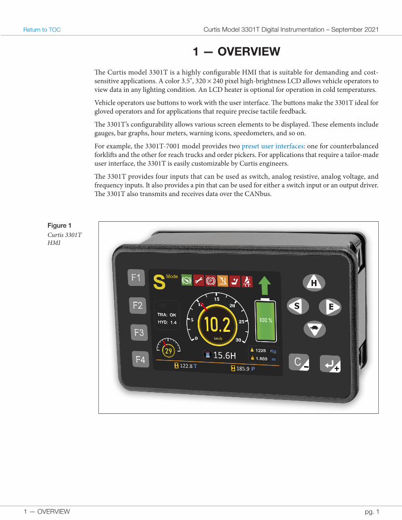
The Curtis model 3301T is a highly configurable HMI that is suitable for demanding and cost-sensitive applications. A color 3.5", 320 × 240 pixel high-brightness LCD allows vehicle operators to view data in any lighting condition. An LCD heater is optional for operation in cold temperatures.
Vehicle operators use buttons to work with the user interface. The buttons make the 3301T ideal for gloved operators and for applications that require precise tactile feedback.
The 3301T’s configurability allows various screen elements to be displayed. These elements include gauges, bar graphs, hour meters, warning icons, speedometers, and so on.
For example, the 3301T-7001 model provides two preset user interfaces: one for counterbalanced forklifts and the other for reach trucks and order pickers. For applications that require a tailor-made user interface, the 3301T is easily customizable by Curtis engineers.
The 3301T provides four inputs that can be used as switch, analog resistive, analog voltage, and frequency inputs. It also provides a pin that can be used for either a switch input or an output driver. The 3301T also transmits and receives data over the CANbus.
Figure 1 Curtis 3301T HMI
1 — OVERVIEW
Curtis Model 3301T Digital Instrumentation – September 2021 Return to TOC
pg. 2
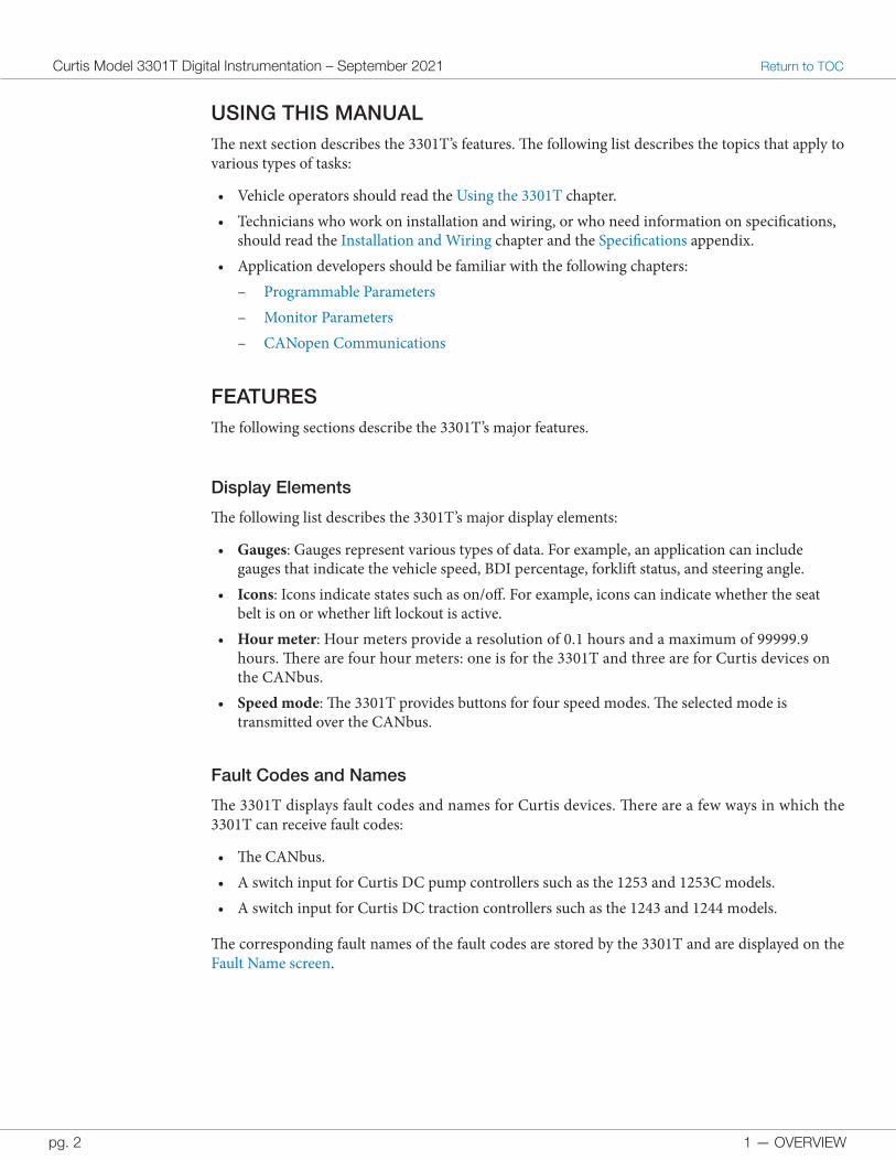
USING THIS MANUALThe next section describes the 3301T’s features. The following list describes the topics that apply to various types of tasks:
• Vehicle operators should read the Using the 3301T chapter.• Technicians who work on installation and wiring, or who need information on specifications,
should read the Installation and Wiring chapter and the Specifications appendix.• Application developers should be familiar with the following chapters:
– Programmable Parameters – Monitor Parameters – CANopen Communications
FEATURESThe following sections describe the 3301T’s major features.
Display Elements
The following list describes the 3301T’s major display elements:
• Gauges: Gauges represent various types of data. For example, an application can include gauges that indicate the vehicle speed, BDI percentage, forklift status, and steering angle.
• Icons: Icons indicate states such as on/off. For example, icons can indicate whether the seat belt is on or whether lift lockout is active.
• Hour meter: Hour meters provide a resolution of 0.1 hours and a maximum of 99999.9 hours. There are four hour meters: one is for the 3301T and three are for Curtis devices on the CANbus.
• Speed mode: The 3301T provides buttons for four speed modes. The selected mode is transmitted over the CANbus.
Fault Codes and Names
The 3301T displays fault codes and names for Curtis devices. There are a few ways in which the 3301T can receive fault codes:
• The CANbus.• A switch input for Curtis DC pump controllers such as the 1253 and 1253C models.• A switch input for Curtis DC traction controllers such as the 1243 and 1244 models.
The corresponding fault names of the fault codes are stored by the 3301T and are displayed on the Fault Name screen.
1 — OVERVIEW pg. 3
Return to TOC Curtis Model 3301T Digital Instrumentation – September 2021
Programming
The 3301T provides the basic functions of the Curtis 1313 Handheld Programmer. Users can read and write parameters for the 3301T and for other Curtis devices that are on the CANbus or connected through the serial port. For more information, see View and Edit Parameters.
LCD Heater
Some models include an LCD heater for vehicles that operate in cold temperatures. The heater extends the minimum operating temperature from −20°C to −40°C. The 3301T turns the heater on when the LCD temperature is below −15°C and off when the LCD is heated to 5°C.
The model number indicates whether a 3301T model has an LCD heater. See the Model Encodement section in the Specifications appendix.
Miscellaneous Features
The following list describes other major features:
• Designed to meet regulatory requirements. For details, see the Specifications appendix.• Multi-language support.• A buzzer alarm that indicates faults.• CANopen, J1939, and an adjustable baud rate allow for seamless communication with any
node on the CANbus.• Password protection for the following functions:
– Power on. A power-on password can optionally be specified. The power-on password is entered with either the 3301T’s buttons or the Curtis Electronic Code Switch (ECS).
– Programming parameters for the 3301T and for other Curtis devices that are on the CANbus or connected to the serial port. There are different passwords for the OEM and User access levels.
– Resetting the hour meters.
Note: For additional information on the 3301T’s features, see the data sheet on the Curtis Instruments CAN & Serial Instrumentation page at https://www.curtisinstruments.com/products/can-serial-instrumentation-programmable.
1 — OVERVIEW
Curtis Model 3301T Digital Instrumentation – September 2021 Return to TOC
pg. 4
CONVENTIONSThe following topics describe terms and notations used in this manual.
Numeral System Notation
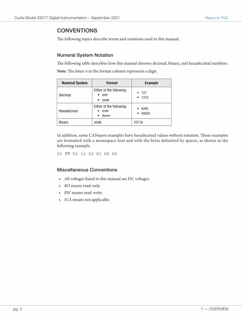
The following table describes how this manual denotes decimal, binary, and hexadecimal numbers.
Note: The letter n in the format column represents a digit.
Numeral System Format Example
DecimalEither of the following:
• nnn• nnnd
• 127• 127d
HexadecimalEither of the following:
• nnnh• 0xnnn
• 62Ah• 0x62A
Binary nnnb 1011b
In addition, some CANopen examples have hexadecimal values without notation. Those examples are formatted with a monospace font and with the bytes delimited by spaces, as shown in the following example:
21 FF 01 11 22 01 00 00
Miscellaneous Conventions
• All voltages listed in this manual are DC voltages.• RO means read-only.• RW means read-write.• N/A means not applicable.
2 — USING THE 3301T pg. 5
Return to TOC Curtis Model 3301T Digital Instrumentation – September 2021
2 — USING THE 3301T
This chapter describes how to use the 3301T’s buttons and screens.
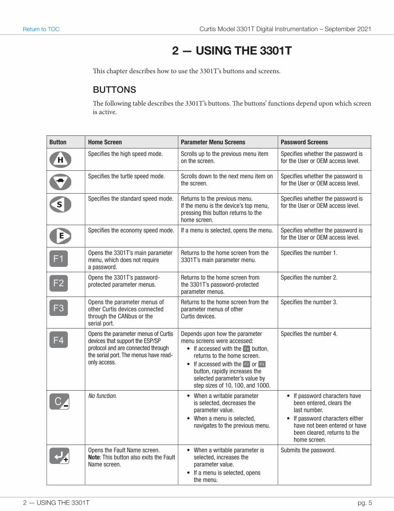
BUTTONSThe following table describes the 3301T’s buttons. The buttons’ functions depend upon which screen is active.
Button Home Screen Parameter Menu Screens Password Screens
HSpecifies the high speed mode. Scrolls up to the previous menu item
on the screen.Specifies whether the password is for the User or OEM access level.
Specifies the turtle speed mode. Scrolls down to the next menu item on the screen.
Specifies whether the password is for the User or OEM access level.
SSpecifies the standard speed mode. Returns to the previous menu.
If the menu is the device’s top menu, pressing this button returns to the home screen.
Specifies whether the password is for the User or OEM access level.
ESpecifies the economy speed mode. If a menu is selected, opens the menu. Specifies whether the password is
for the User or OEM access level.
F1Opens the 3301T’s main parameter menu, which does not require a password.
Returns to the home screen from the 3301T’s main parameter menu.
Specifies the number 1.
F2Opens the 3301T’s password-protected parameter menus.
Returns to the home screen from the 3301T’s password-protected parameter menus.
Specifies the number 2.
F3Opens the parameter menus of other Curtis devices connected through the CANbus or the serial port.
Returns to the home screen from the parameter menus of other Curtis devices.
Specifies the number 3.
F4Opens the parameter menus of Curtis devices that support the ESP/SP protocol and are connected through the serial port. The menus have read-only access.
Depends upon how the parameter menu screens were accessed:
• If accessed with the F4 button, returns to the home screen.
• If accessed with the F2 or F3 button, rapidly increases the selected parameter’s value by step sizes of 10, 100, and 1000.
Specifies the number 4.
C--No function. • When a writable parameter
is selected, decreases the parameter value.
• When a menu is selected, navigates to the previous menu.
• If password characters have been entered, clears the last number.
• If password characters either have not been entered or have been cleared, returns to the home screen.
++Opens the Fault Name screen.Note: This button also exits the Fault Name screen.
• When a writable parameter is selected, increases the parameter value.
• If a menu is selected, opens the menu.
Submits the password.
2 — USING THE 3301T
Curtis Model 3301T Digital Instrumentation – September 2021 Return to TOC
pg. 6
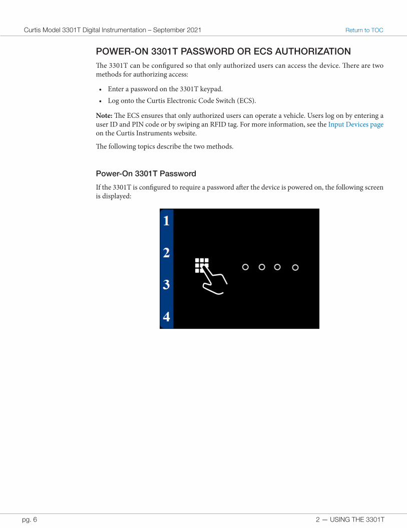
POWER-ON 3301T PASSWORD OR ECS AUTHORIZATIONThe 3301T can be configured so that only authorized users can access the device. There are two methods for authorizing access:
• Enter a password on the 3301T keypad.• Log onto the Curtis Electronic Code Switch (ECS).
Note: The ECS ensures that only authorized users can operate a vehicle. Users log on by entering a user ID and PIN code or by swiping an RFID tag. For more information, see the Input Devices page on the Curtis Instruments website.
The following topics describe the two methods.
Power-On 3301T Password
If the 3301T is configured to require a password after the device is powered on, the following screen is displayed:
2 — USING THE 3301T pg. 7
Return to TOC Curtis Model 3301T Digital Instrumentation – September 2021
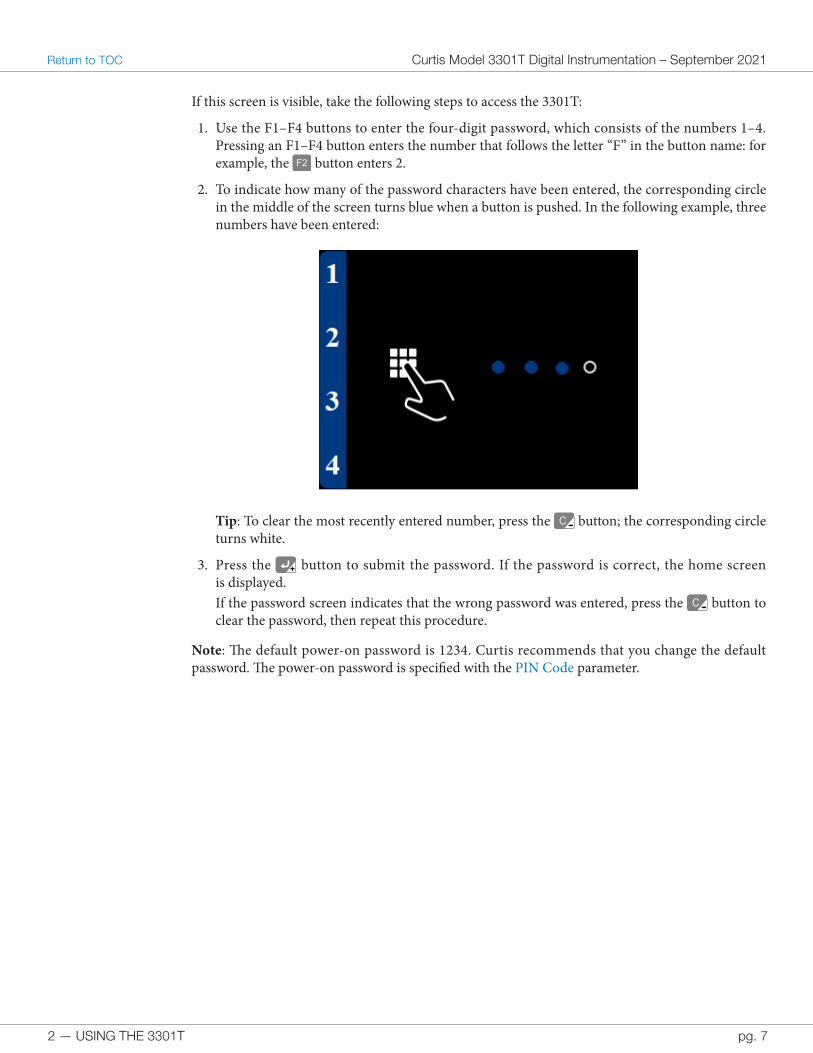
If this screen is visible, take the following steps to access the 3301T:
1. Use the F1–F4 buttons to enter the four-digit password, which consists of the numbers 1–4. Pressing an F1–F4 button enters the number that follows the letter “F” in the button name: for example, the F2 button enters 2.
2. To indicate how many of the password characters have been entered, the corresponding circle in the middle of the screen turns blue when a button is pushed. In the following example, three numbers have been entered:
Tip: To clear the most recently entered number, press the C-- button; the corresponding circle turns white.
3. Press the ++ button to submit the password. If the password is correct, the home screen is displayed.If the password screen indicates that the wrong password was entered, press the C-- button to clear the password, then repeat this procedure.
Note: The default power-on password is 1234. Curtis recommends that you change the default password. The power-on password is specified with the PIN Code parameter.
2 — USING THE 3301T
Curtis Model 3301T Digital Instrumentation – September 2021 Return to TOC
pg. 8
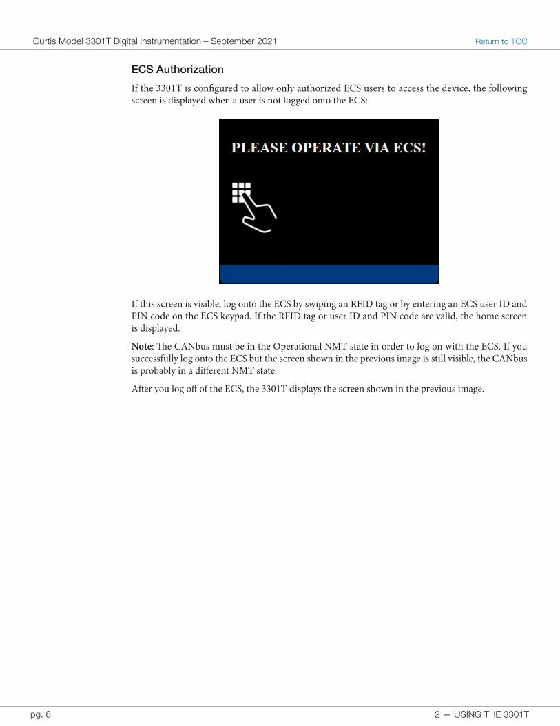
ECS Authorization
If the 3301T is configured to allow only authorized ECS users to access the device, the following screen is displayed when a user is not logged onto the ECS:
If this screen is visible, log onto the ECS by swiping an RFID tag or by entering an ECS user ID and PIN code on the ECS keypad. If the RFID tag or user ID and PIN code are valid, the home screen is displayed.
Note: The CANbus must be in the Operational NMT state in order to log on with the ECS. If you successfully log onto the ECS but the screen shown in the previous image is still visible, the CANbus is probably in a different NMT state.
After you log off of the ECS, the 3301T displays the screen shown in the previous image.
2 — USING THE 3301T pg. 9
Return to TOC Curtis Model 3301T Digital Instrumentation – September 2021
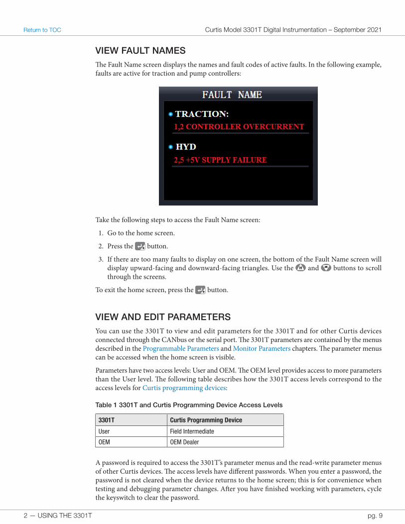
VIEW FAULT NAMESThe Fault Name screen displays the names and fault codes of active faults. In the following example, faults are active for traction and pump controllers:
Take the following steps to access the Fault Name screen:
1. Go to the home screen.
2. Press the ++ button.
3. If there are too many faults to display on one screen, the bottom of the Fault Name screen will display upward-facing and downward-facing triangles. Use the H and buttons to scroll through the screens.
To exit the home screen, press the ++ button.
VIEW AND EDIT PARAMETERSYou can use the 3301T to view and edit parameters for the 3301T and for other Curtis devices connected through the CANbus or the serial port. The 3301T parameters are contained by the menus described in the Programmable Parameters and Monitor Parameters chapters. The parameter menus can be accessed when the home screen is visible.
Parameters have two access levels: User and OEM. The OEM level provides access to more parameters than the User level. The following table describes how the 3301T access levels correspond to the access levels for Curtis programming devices:
Table 1 3301T and Curtis Programming Device Access Levels
3301T Curtis Programming Device
User Field Intermediate
OEM OEM Dealer
A password is required to access the 3301T’s parameter menus and the read-write parameter menus of other Curtis devices. The access levels have different passwords. When you enter a password, the password is not cleared when the device returns to the home screen; this is for convenience when testing and debugging parameter changes. After you have finished working with parameters, cycle the keyswitch to clear the password.
2 — USING THE 3301T
Curtis Model 3301T Digital Instrumentation – September 2021 Return to TOC
pg. 10
The following list describes the default passwords for accessing parameter menus:
• User access level: 1111• OEM access level: 2222
Curtis recommends that you change the default passwords. Passwords are changed with the OEM Menu Password and USER Menu Password parameters on the Password menu.
The following topics describe how to open and use the screens.
Open the 3301T’s Main Menu
The 3301T’s main menu is not password-protected. Take the following steps to open the main menu.
Note: The parameters contained by the Monitor and Program menus are password-protected. To open them, perform the steps in the next section.
1. Go to the home screen.
2. Press the F1 button. The main menu displays and you can now view and edit parameters.
To exit the menu, press the F1 button.
Open the 3301T’s Parameter Menus
You must enter a password to open all of the 3301T’s menus, which include the main menu, Program menu, and Monitor menu. Take the following steps to open these menus.
1. Go to the home screen.
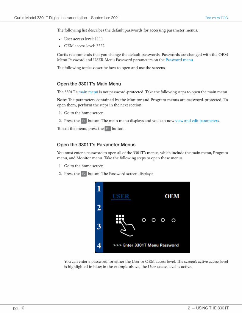
2. Press the F2 button. The Password screen displays:
You can enter a password for either the User or OEM access level. The screen’s active access level is highlighted in blue; in the example above, the User access level is active.
2 — USING THE 3301T pg. 11
Return to TOC Curtis Model 3301T Digital Instrumentation – September 2021
3. To change the active access level, press the S , E , H , or button.
4. Use the F1–F4 buttons to enter the four-digit password, which consists of the numbers 1–4. Pressing an F1–F4 button enters the number that follows the letter “F” in the button name: for example, the F2 button enters 2.
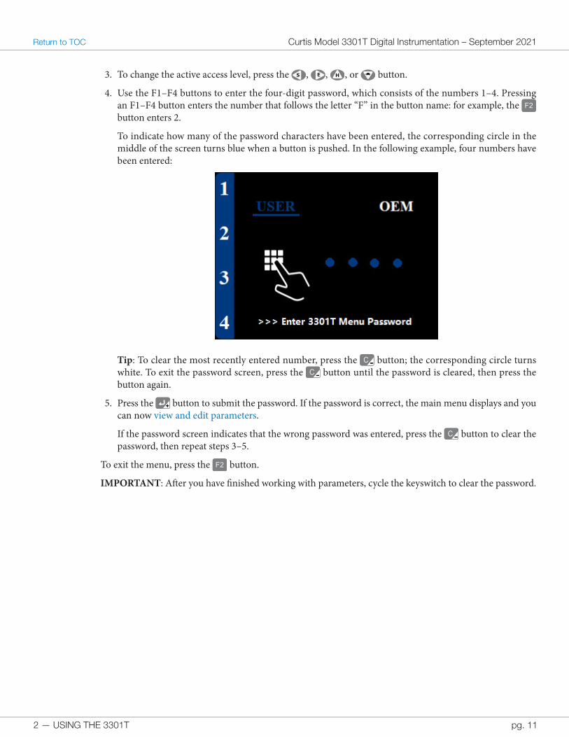
To indicate how many of the password characters have been entered, the corresponding circle in the middle of the screen turns blue when a button is pushed. In the following example, four numbers have been entered:
Tip: To clear the most recently entered number, press the C-- button; the corresponding circle turns white. To exit the password screen, press the C-- button until the password is cleared, then press the button again.
5. Press the ++ button to submit the password. If the password is correct, the main menu displays and you can now view and edit parameters.
If the password screen indicates that the wrong password was entered, press the C-- button to clear the password, then repeat steps 3–5.
To exit the menu, press the F2 button.
IMPORTANT: After you have finished working with parameters, cycle the keyswitch to clear the password.
2 — USING THE 3301T
Curtis Model 3301T Digital Instrumentation – September 2021 Return to TOC
pg. 12
Open Read-Write Parameter Menus for Other Curtis Devices
The 3301T allows you to view and edit parameters of Curtis devices that are connected through the CANbus or that support the ESP/SP protocol and are connected through the serial port. Take the following steps to open other Curtis devices’ menus.
1. Go to the home screen.
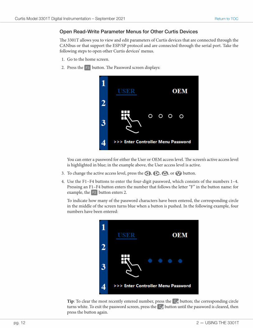
2. Press the F3 button. The Password screen displays:
You can enter a password for either the User or OEM access level. The screen’s active access level is highlighted in blue; in the example above, the User access level is active.
3. To change the active access level, press the S , E , H , or button.
4. Use the F1–F4 buttons to enter the four-digit password, which consists of the numbers 1–4. Pressing an F1–F4 button enters the number that follows the letter “F” in the button name: for example, the F2 button enters 2.
To indicate how many of the password characters have been entered, the corresponding circle in the middle of the screen turns blue when a button is pushed. In the following example, four numbers have been entered:
Tip: To clear the most recently entered number, press the C-- button; the corresponding circle turns white. To exit the password screen, press the C-- button until the password is cleared, then press the button again.
2 — USING THE 3301T pg. 13
Return to TOC Curtis Model 3301T Digital Instrumentation – September 2021
5. Press the ++ button to submit the password. If the password is correct, the 3301T will list the Curtis devices on the CANbus.If the password screen indicates that the wrong password was entered, press the C-- button to clear the password, then repeat steps 3–5.
6. If multiple devices are listed, use the and H buttons to select the device you want to work with.
7. Press the ++ button. The 3301T downloads the device’s menu and then displays the main menu. You can now view and edit parameters.
To exit the menu, press the F3 button.
IMPORTANT: After you have finished working with parameters, cycle the keyswitch to clear the password.
Open Read-Only Parameter Menus of Devices Connected to the Serial Port
The 3301T provides read-only access to the main and Monitor menus of Curtis devices that support the ESP/SP protocol and are connected through the serial port. Take the following steps to open these menus:
1. Go to the home screen.
2. Press the F4 button. The main menu displays and you can now view parameters.
To exit the menus, press the F4 button.
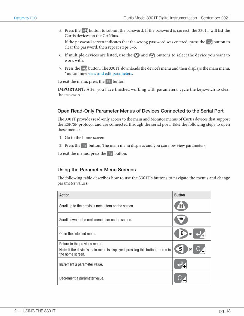
Using the Parameter Menu Screens
The following table describes how to use the 3301T’s buttons to navigate the menus and change parameter values:
Action Button
Scroll up to the previous menu item on the screen. H
Scroll down to the next menu item on the screen.
Open the selected menu. E or ++
Return to the previous menu.
Note: If the device’s main menu is displayed, pressing this button returns to the home screen.
S or C--Increment a parameter value. ++
Decrement a parameter value. C--
2 — USING THE 3301T
Curtis Model 3301T Digital Instrumentation – September 2021 Return to TOC
pg. 14
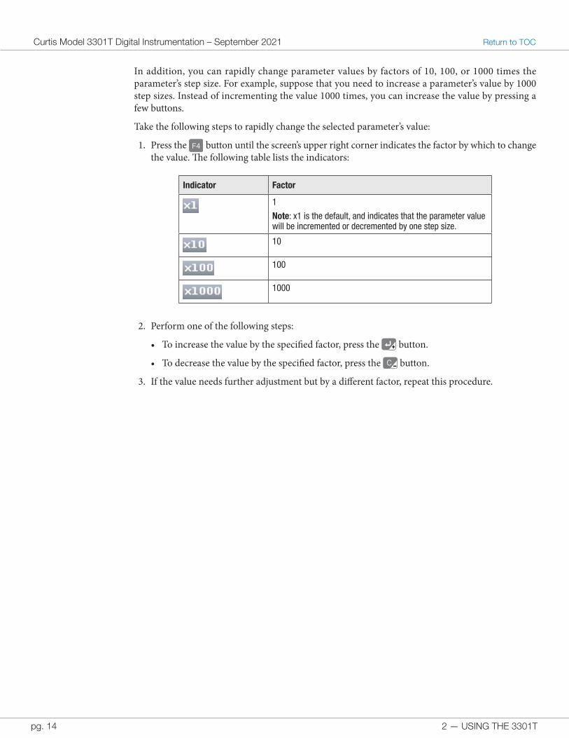
In addition, you can rapidly change parameter values by factors of 10, 100, or 1000 times the parameter’s step size. For example, suppose that you need to increase a parameter’s value by 1000 step sizes. Instead of incrementing the value 1000 times, you can increase the value by pressing a few buttons.
Take the following steps to rapidly change the selected parameter’s value:
1. Press the F4 button until the screen’s upper right corner indicates the factor by which to change the value. The following table lists the indicators:
Indicator Factor
1
Note: x1 is the default, and indicates that the parameter value will be incremented or decremented by one step size.
10
100
1000
2. Perform one of the following steps:
• To increase the value by the specified factor, press the ++ button.
• To decrease the value by the specified factor, press the C-- button.
3. If the value needs further adjustment but by a different factor, repeat this procedure.
2 — USING THE 3301T pg. 15
Return to TOC Curtis Model 3301T Digital Instrumentation – September 2021
ALARM BUZZERThe 3301T has a buzzer that emits sounds through the rear of the device. The buzzer is activated when the 3301T receives a fault code through the CANbus or through the fault code inputs for the DC traction and pump controllers.
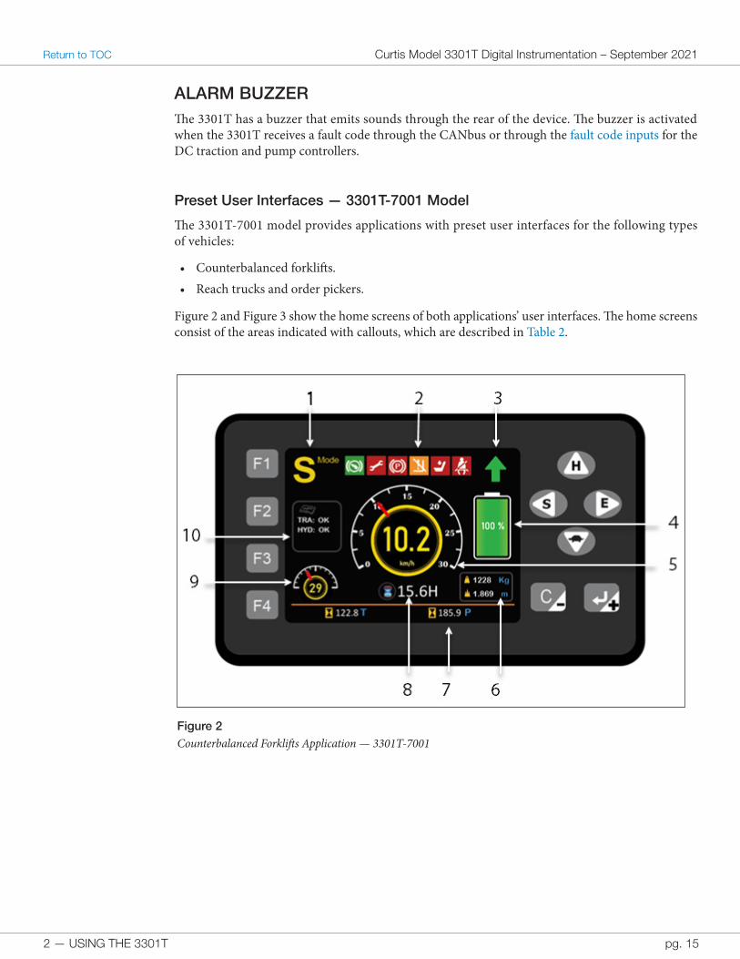
Preset User Interfaces — 3301T-7001 Model
The 3301T-7001 model provides applications with preset user interfaces for the following types of vehicles:
• Counterbalanced forklifts.• Reach trucks and order pickers.
Figure 2 and Figure 3 show the home screens of both applications’ user interfaces. The home screens consist of the areas indicated with callouts, which are described in Table 2.
Figure 2 Counterbalanced Forklifts Application — 3301T-7001
2 — USING THE 3301T
Curtis Model 3301T Digital Instrumentation – September 2021 Return to TOC
pg. 16
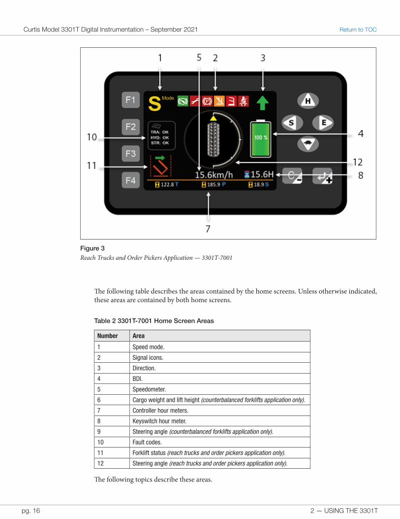
Figure 3 Reach Trucks and Order Pickers Application — 3301T-7001
The following table describes the areas contained by the home screens. Unless otherwise indicated, these areas are contained by both home screens.
Table 2 3301T-7001 Home Screen Areas
Number Area
1 Speed mode.
2 Signal icons.
3 Direction.
4 BDI.
5 Speedometer.
6 Cargo weight and lift height (counterbalanced forklifts application only).
7 Controller hour meters.
8 Keyswitch hour meter.
9 Steering angle (counterbalanced forklifts application only).
10 Fault codes.
11 Forklift status (reach trucks and order pickers application only).
12 Steering angle (reach trucks and order pickers application only).
The following topics describe these areas.
2 — USING THE 3301T pg. 17
Return to TOC Curtis Model 3301T Digital Instrumentation – September 2021
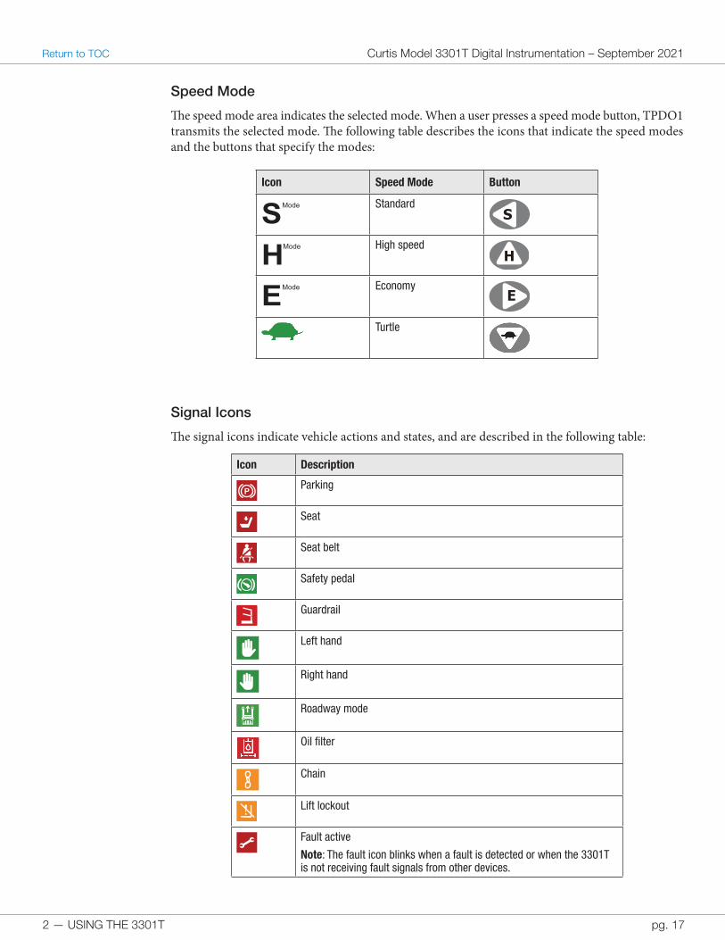
Speed Mode
The speed mode area indicates the selected mode. When a user presses a speed mode button, TPDO1 transmits the selected mode. The following table describes the icons that indicate the speed modes and the buttons that specify the modes:
Icon Speed Mode Button
SMode StandardS
HMode High speedH
EMode EconomyE
Turtle
Signal Icons
The signal icons indicate vehicle actions and states, and are described in the following table:
Icon Description
PParking
Seat
Seat belt
Safety pedal
Guardrail
Left hand
Right hand
Roadway mode
Oil filter
Chain
Lift lockout
Fault active
Note: The fault icon blinks when a fault is detected or when the 3301T is not receiving fault signals from other devices.
2 — USING THE 3301T
Curtis Model 3301T Digital Instrumentation – September 2021 Return to TOC
pg. 18
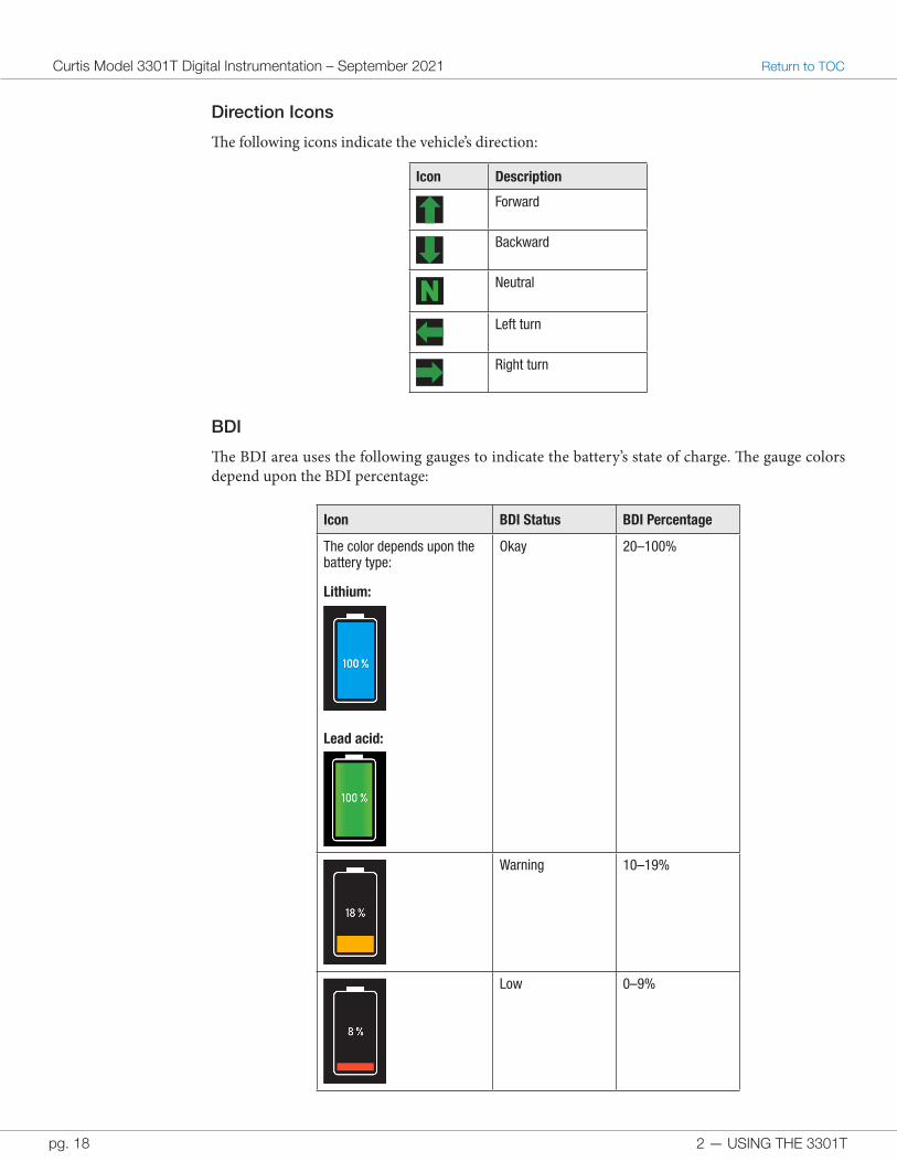
Direction Icons
The following icons indicate the vehicle’s direction:
Icon Description
Forward
Backward
NN Neutral
Left turn
Right turn
BDI
The BDI area uses the following gauges to indicate the battery’s state of charge. The gauge colors depend upon the BDI percentage:
Icon BDI Status BDI Percentage
The color depends upon the battery type:
Lithium:
Lead acid:
Okay 20–100%
Warning 10–19%
Low 0–9%
2 — USING THE 3301T pg. 19
Return to TOC Curtis Model 3301T Digital Instrumentation – September 2021
The Warning and Low icons flash when they are active. If the BDI percentage is too low, lift lockout is activated, and the icon displays.
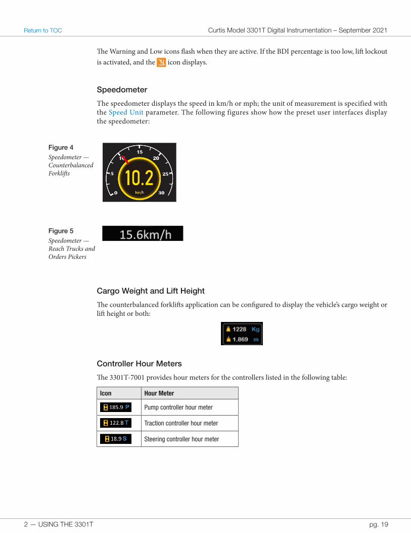
Speedometer
The speedometer displays the speed in km/h or mph; the unit of measurement is specified with the Speed Unit parameter. The following figures show how the preset user interfaces display the speedometer:
Figure 4 Speedometer — Counterbalanced Forklifts
Figure 5 Speedometer — Reach Trucks and Orders Pickers
Cargo Weight and Lift Height
The counterbalanced forklifts application can be configured to display the vehicle’s cargo weight or lift height or both:
Controller Hour Meters
The 3301T-7001 provides hour meters for the controllers listed in the following table:
Icon Hour Meter
Pump controller hour meter
Traction controller hour meter
Steering controller hour meter
2 — USING THE 3301T
Curtis Model 3301T Digital Instrumentation – September 2021 Return to TOC
pg. 20
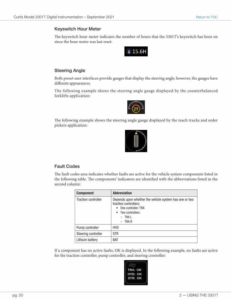
Keyswitch Hour Meter
The keyswitch hour meter indicates the number of hours that the 3301T’s keyswitch has been on since the hour meter was last reset:
Steering Angle
Both preset user interfaces provide gauges that display the steering angle; however, the gauges have different appearances.
The following example shows the steering angle gauge displayed by the counterbalanced forklifts application:
The following example shows the steering angle gauge displayed by the reach trucks and order pickers application:
Fault Codes
The fault codes area indicates whether faults are active for the vehicle system components listed in the following table. The components’ indicators are identified with the abbreviations listed in the second column:
Component Abbreviation
Traction controller Depends upon whether the vehicle system has one or two traction controllers:
• One controller: TRA• Two controllers:
+ TRA L+ TRA R
Pump controller HYD
Steering controller STR
Lithium battery BAT
If a component has no active faults, OK is displayed. In the following example, no faults are active for the traction controller, pump controller, and steering controller:

2 — USING THE 3301T pg. 21
Return to TOC Curtis Model 3301T Digital Instrumentation – September 2021
A fault code displays if a component has active faults. In the following example, the steering controller has an active fault identified by the fault code 1, 8:
Note: The 3301T also displays fault names. See View Fault Names.
Forklift Status
The reach trucks and order pickers application contains the forklift status area. The following icons indicate the lift’s action and direction:
Icon Lift Status
Inactive lift
Lift up
Lift down
Lift left
Lift right
Lift up and left
Lift up and right
Lift down and left
Lift down and right
Rotate clockwise
Rotate counterclockwise
Shift left
Shift right
3 — INSTALLATION AND WIRING
Curtis Model 3301T Digital Instrumentation – September 2021 Return to TOC
pg. 22
3 — INSTALLATION AND WIRING
This chapter explains how to install and wire the 3301T.
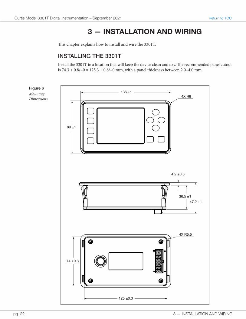
INSTALLING THE 3301TInstall the 3301T in a location that will keep the device clean and dry. The recommended panel cutout is 74.3 + 0.8/–0 × 125.3 + 0.8/–0 mm, with a panel thickness between 2.0–4.0 mm.
Figure 6Mounting Dimensions
125 ±0.3
74 ±0.3
36.5 ±1
4.2 ±0.3
47.2 ±1
80 ±1
136 ±1 4X R8
4X R5.5
3 — INSTALLATION AND WIRING pg. 23
Return to TOC Curtis Model 3301T Digital Instrumentation – September 2021
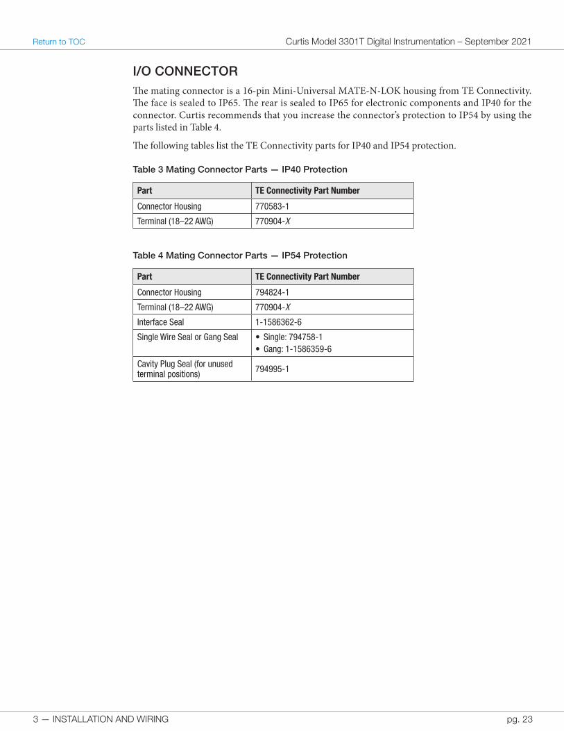
I/O CONNECTORThe mating connector is a 16-pin Mini-Universal MATE-N-LOK housing from TE Connectivity. The face is sealed to IP65. The rear is sealed to IP65 for electronic components and IP40 for the connector. Curtis recommends that you increase the connector’s protection to IP54 by using the parts listed in Table 4.
The following tables list the TE Connectivity parts for IP40 and IP54 protection.
Table 3 Mating Connector Parts — IP40 Protection
Part TE Connectivity Part Number
Connector Housing 770583-1
Terminal (18–22 AWG) 770904-X
Table 4 Mating Connector Parts — IP54 Protection
Part TE Connectivity Part Number
Connector Housing 794824-1
Terminal (18–22 AWG) 770904-X
Interface Seal 1-1586362-6
Single Wire Seal or Gang Seal • Single: 794758-1• Gang: 1-1586359-6
Cavity Plug Seal (for unused terminal positions) 794995-1

3 — INSTALLATION AND WIRING
Curtis Model 3301T Digital Instrumentation – September 2021 Return to TOC
pg. 24
I/O PINS
Table 5 I/O Pins
Pin Signal Name Description
1 SCI Rx Serial communications — Rx.
2 SCI GND Serial communications — ground.
3 CAN_L CAN low.
4 CAN_L Termination CAN 120Ω termination resistor — low.
5 Switch Input1/Analog Input1/Frequency Input 1
Input for switch, analog, or frequency signals.
6 Switch Input3/Analog Input3/HYD Fault Code Input
Input for switch, analog, or hydraulic controller fault code signals.
7 Keyswitch
8 Switch Input5/MOSFET OUTPUT Switch input or driver output.
9 SCI Tx Serial communications — Tx.
10 CAN_GND CAN ground.
11 CAN_H CAN high.
12 CAN_H Termination CAN 120Ω termination resistor — high.
13 Switch Input2/Analog Input2/Frequency Input 2
Input for switch, analog, or frequency signals.
14 Switch Input4/Analog Input4/TRA Fault Code Input
Input for switch, analog, or traction controller fault code signals.
15 B–
16 B+
3 — INSTALLATION AND WIRING pg. 25
Return to TOC Curtis Model 3301T Digital Instrumentation – September 2021
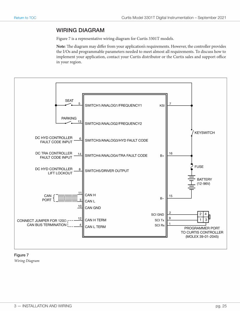
WIRING DIAGRAMFigure 7 is a representative wiring diagram for Curtis 3301T models.
Note: The diagram may differ from your application’s requirements. However, the controller provides the I/Os and programmable parameters needed to meet almost all requirements. To discuss how to implement your application, contact your Curtis distributor or the Curtis sales and support office in your region.
Figure 7Wiring Diagram
SCI Rx
SCI Tx
SCI GND
CAN H
CAN L
CAN GND
CONNECT JUMPER FOR 120ΩCAN BUS TERMINATION
CAN H TERM
CAN L TERM
SWITCH1/ANALOG1/FREQUENCY1
SWITCH2/ANALOG2/FREQUENCY2
SWITCH3/ANALOG3/HYD FAULT CODE
SWITCH4/ANALOG4/TRA FAULT CODE
KSI
B+
B−
SWITCH5/DRIVER OUTPUTFUSE
CAN PORT
DC HYD CONTROLLERFAULT CODE INPUT
DC TRA CONTROLLERFAULT CODE INPUT
DC HYD CONTROLLERLIFT LOCKOUT
BATTERY(12-96V)
SEAT
PARKING
KEYSWITCH
PROGRAMMER PORTTO CURTIS CONTROLLER
(MOLEX 39-01-2045)
7
1
9
2
15
16
12
4
10
11
3
8
14
6
13
5
1
2
3
4
3 — INSTALLATION AND WIRING
Curtis Model 3301T Digital Instrumentation – September 2021 Return to TOC
pg. 26
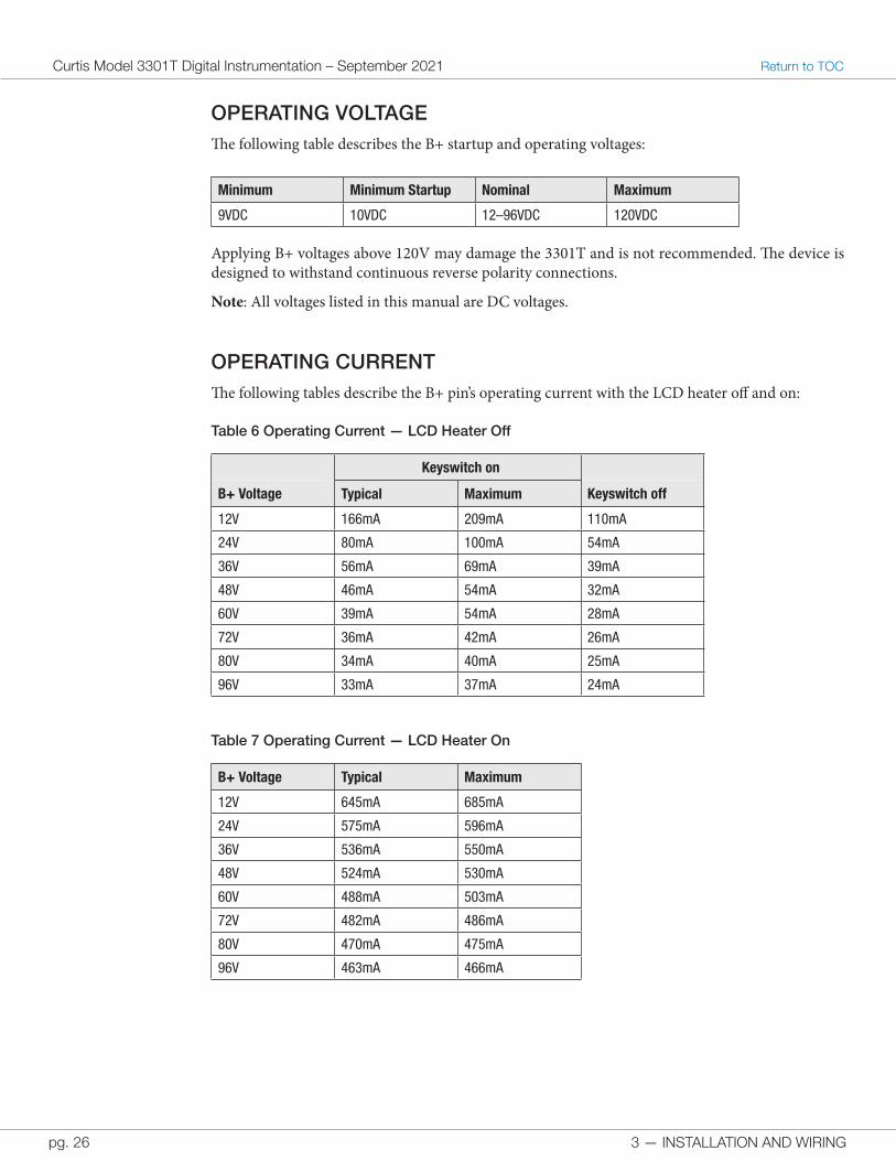
OPERATING VOLTAGEThe following table describes the B+ startup and operating voltages:
Minimum Minimum Startup Nominal Maximum
9VDC 10VDC 12–96VDC 120VDC
Applying B+ voltages above 120V may damage the 3301T and is not recommended. The device is designed to withstand continuous reverse polarity connections.
Note: All voltages listed in this manual are DC voltages.
OPERATING CURRENTThe following tables describe the B+ pin’s operating current with the LCD heater off and on:
Table 6 Operating Current — LCD Heater Off
Keyswitch on
B+ Voltage Typical Maximum Keyswitch off
12V 166mA 209mA 110mA
24V 80mA 100mA 54mA
36V 56mA 69mA 39mA
48V 46mA 54mA 32mA
60V 39mA 54mA 28mA
72V 36mA 42mA 26mA
80V 34mA 40mA 25mA
96V 33mA 37mA 24mA
Table 7 Operating Current — LCD Heater On
B+ Voltage Typical Maximum
12V 645mA 685mA
24V 575mA 596mA
36V 536mA 550mA
48V 524mA 530mA
60V 488mA 503mA
72V 482mA 486mA
80V 470mA 475mA
96V 463mA 466mA
3 — INSTALLATION AND WIRING pg. 27
Return to TOC Curtis Model 3301T Digital Instrumentation – September 2021
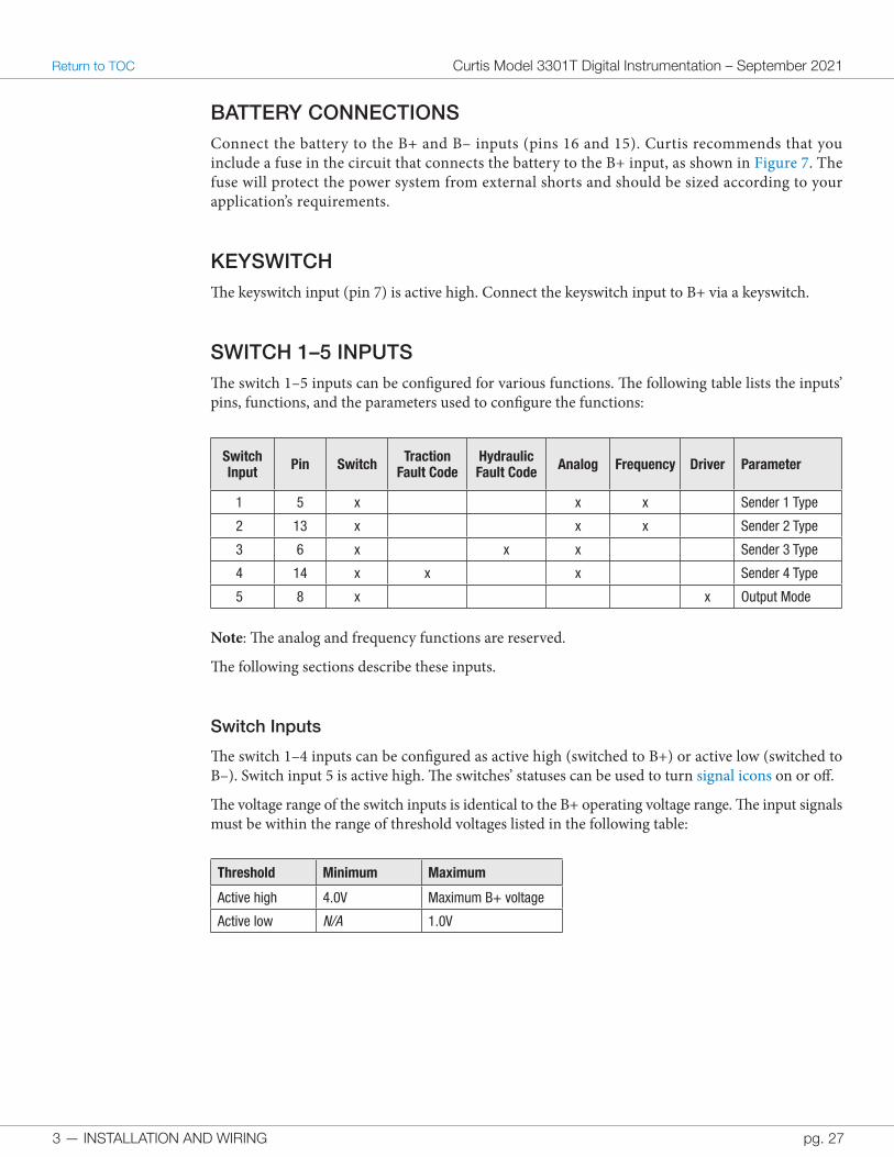
BATTERY CONNECTIONSConnect the battery to the B+ and B– inputs (pins 16 and 15). Curtis recommends that you include a fuse in the circuit that connects the battery to the B+ input, as shown in Figure 7. The fuse will protect the power system from external shorts and should be sized according to your application’s requirements.
KEYSWITCHThe keyswitch input (pin 7) is active high. Connect the keyswitch input to B+ via a keyswitch.
SWITCH 1–5 INPUTSThe switch 1–5 inputs can be configured for various functions. The following table lists the inputs’ pins, functions, and the parameters used to configure the functions:
Switch Input Pin Switch Traction
Fault CodeHydraulic Fault Code Analog Frequency Driver Parameter
1 5 x x x Sender 1 Type
2 13 x x x Sender 2 Type
3 6 x x x Sender 3 Type
4 14 x x x Sender 4 Type
5 8 x x Output Mode
Note: The analog and frequency functions are reserved.
The following sections describe these inputs.
Switch Inputs
The switch 1–4 inputs can be configured as active high (switched to B+) or active low (switched to B–). Switch input 5 is active high. The switches’ statuses can be used to turn signal icons on or off.
The voltage range of the switch inputs is identical to the B+ operating voltage range. The input signals must be within the range of threshold voltages listed in the following table:
Threshold Minimum Maximum
Active high 4.0V Maximum B+ voltage
Active low N/A 1.0V
3 — INSTALLATION AND WIRING
Curtis Model 3301T Digital Instrumentation – September 2021 Return to TOC
pg. 28
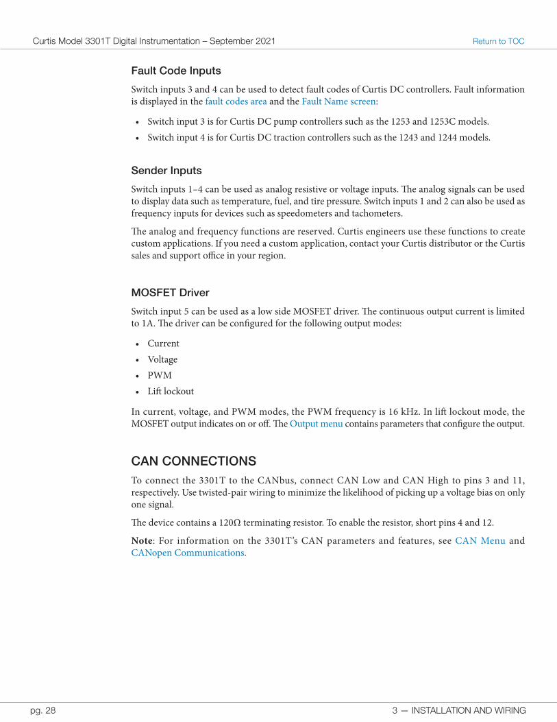
Fault Code Inputs
Switch inputs 3 and 4 can be used to detect fault codes of Curtis DC controllers. Fault information is displayed in the fault codes area and the Fault Name screen:
• Switch input 3 is for Curtis DC pump controllers such as the 1253 and 1253C models.• Switch input 4 is for Curtis DC traction controllers such as the 1243 and 1244 models.
Sender Inputs
Switch inputs 1–4 can be used as analog resistive or voltage inputs. The analog signals can be used to display data such as temperature, fuel, and tire pressure. Switch inputs 1 and 2 can also be used as frequency inputs for devices such as speedometers and tachometers.
The analog and frequency functions are reserved. Curtis engineers use these functions to create custom applications. If you need a custom application, contact your Curtis distributor or the Curtis sales and support office in your region.
MOSFET Driver
Switch input 5 can be used as a low side MOSFET driver. The continuous output current is limited to 1A. The driver can be configured for the following output modes:
• Current• Voltage• PWM• Lift lockout
In current, voltage, and PWM modes, the PWM frequency is 16 kHz. In lift lockout mode, the MOSFET output indicates on or off. The Output menu contains parameters that configure the output.
CAN CONNECTIONSTo connect the 3301T to the CANbus, connect CAN Low and CAN High to pins 3 and 11, respectively. Use twisted-pair wiring to minimize the likelihood of picking up a voltage bias on only one signal.
The device contains a 120Ω terminating resistor. To enable the resistor, short pins 4 and 12.
Note: For information on the 3301T’s CAN parameters and features, see CAN Menu and CANopen Communications.
4 — PROGRAMMABLE PARAMETERS pg. 29
Return to TOC Curtis Model 3301T Digital Instrumentation – September 2021
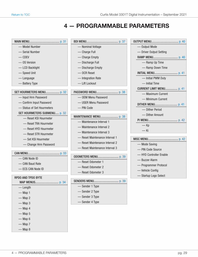
4 — PROGRAMMABLE PARAMETERS
MAIN MENU....................................... p. 31
— Model Number
— Serial Number
— CDEV
— OS Version
— LCD Backlight
— Speed Unit
— Language
— Battery Type
SET HOURMETERS MENU.................. p. 32
— Input Hrm Password
— Confirm Input Password
— Status of Set Hourmeters
SET HOURMETERS SUBMENU..... p. 32
— Reset KSI Hourmeter
— Reset TRA Hourmeter
— Reset HYD Hourmeter
— Reset STR Hourmeter
— Set KSI Hourmeter
— Change Hrm Password
CAN MENU......................................... p. 33
— CAN Node ID
— CAN Baud Rate
— ECS CAN Node ID
RPD O AND TPDO BYTE MAP MENUS.............................. p. 34
— Length
— Map 1
— Map 2
— Map 3
— Map 4
— Map 5
— Map 6
— Map 7
— Map 8
BDI MENU......................................... p. 37
— Nominal Voltage
— Charge Full
— Charge Empty
— Discharge Full
— Discharge Empty
— OCR Reset
— Integration Rate
— Lift Lockout
PASSWORD MENU............................ p. 38
— OEM Menu Password
— USER Menu Password
— PIN Code
MAINTENANCE MENU....................... p. 38
— Maintenance Interval 1
— Maintenance Interval 2
— Maintenance Interval 3
— Reset Maintenance Interval 1
— Reset Maintenance Interval 2
— Reset Maintenance Interval 3
ODOMETERS MENU........................... p. 39
— Reset Odometer 1
— Reset Odometer 2
— Reset Odometer 3
SENDERS MENU................................ p. 39
— Sender 1 Type
— Sender 2 Type
— Sender 3 Type
— Sender 4 Type
OUTPUT MENU................................... p. 40
— Output Mode
— Driver Output Setting
RAMP MENU................................ p. 40
— Ramp Up Time
— Ramp Down Time
INITIAL MENU.............................. p. 41
— Initial PWM Duty
— Initial Time
CURRENT LIMIT MENU................ p. 41
— Maximum Current
— Minimum Current
DITHER MENU............................. p. 41
— Dither Period
— Dither Amount
PI MENU...................................... p. 42
— Kp
— Ki
MISC MENU....................................... p. 42
— Mode Saving
— PIN Code Source
— HYD Controller Enable
— Buzzer Alarm
— Programmer Protocol
— Vehicle Config
— Startup Logo Select
4 — PROGRAMMABLE PARAMETERS
Curtis Model 3301T Digital Instrumentation – September 2021 Return to TOC
pg. 30
The programmable parameters allow you to configure the 3301T so that it meets your application’s requirements. Curtis programming devices provide a user-friendly way to read and write to the parameters. You can also use the 3301T to read and write to parameters; see View and Edit Parameters.
Restart the device after you change a parameter marked as [PCF]. If the device is not restarted, a Parameter Change fault will occur.
The parameters are grouped into menus. This chapter describes the main menu and the menus contained by the Program menu, and the Monitor Parameters chapter describes the menus contained by the Monitor menu.
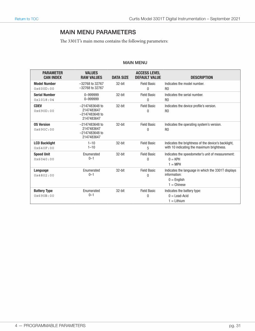
The following columns in the parameter description tables contain multiple types of information:
• Parameter and CAN Index: The parameter name, followed by the CAN index and sub-index. This column also identifies parameters marked as [PCF].Note: CAN indexes and sub-indexes are delimited by colons. For example, a parameter with an index of 0x640F and a sub-index of 0x00 would be represented as 0x640F:00.
• Values and Raw Values: The allowed values as displayed in Curtis programming devices, followed by allowed values in raw units suitable for CAN messages.
• Access Level and Default Value. The parameter’s access level for Curtis programming devices, followed by the default value.Note: Table 1 describes how the Curtis programming device access levels correspond to the 3301T access levels.
Most of the parameters described in this chapter are read-write. If a parameter is read-only, the last line of the Description column will consist of “RO”.
4 — PROGRAMMABLE PARAMETERS pg. 31
Return to TOC Curtis Model 3301T Digital Instrumentation – September 2021
MAIN MENU PARAMETERSThe 3301T’s main menu contains the following parameters:
MAIN MENU
PARAMETERCAN INDEX
VALUESRAW VALUES DATA SIZE
ACCESS LEVELDEFAULT VALUE DESCRIPTION
Model Number0x600D:00
–32768 to 32767–32768 to 32767
32-bit Field Basic0
Indicates the model number. RO
Serial Number0x1018:04
0–9999990–999999
32-bit Field Basic0
Indicates the serial number. RO
CDEV0x690D:00
–2147483648 to 2147483647
–2147483648 to 2147483647
32-bit Field Basic0
Indicates the device profile’s version. RO
OS Version0x690C:00
–2147483648 to 2147483647
–2147483648 to 2147483647
32-bit Field Basic0
Indicates the operating system’s version. RO
LCD Backlight0x640F:00
1–101–10
32-bit Field Basic5
Indicates the brightness of the device’s backlight, with 10 indicating the maximum brightness.
Speed Unit0x6040:00
Enumerated0–1
32-bit Field Basic0
Indicates the speedometer’s unit of measurement:0 = KPH1 = MPH
Language0x4802:00
Enumerated0–1
32-bit Field Basic0
Indicates the language in which the 3301T displays information:
0 = English1 = Chinese
Battery Type0x690B:00
Enumerated0–1
32-bit Field Basic0
Indicates the battery type:0 = Lead-Acid1 = Lithium
4 — PROGRAMMABLE PARAMETERS
Curtis Model 3301T Digital Instrumentation – September 2021 Return to TOC
pg. 32
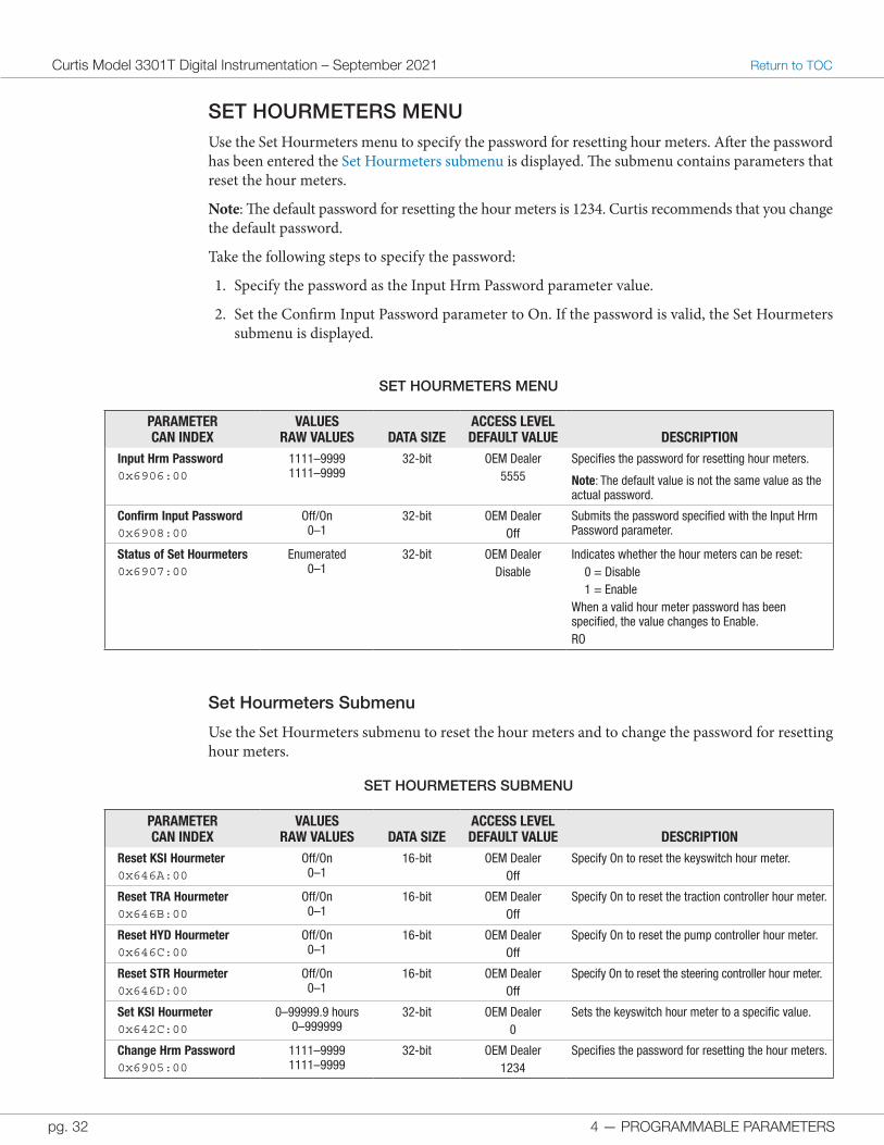
SET HOURMETERS MENUUse the Set Hourmeters menu to specify the password for resetting hour meters. After the password has been entered the Set Hourmeters submenu is displayed. The submenu contains parameters that reset the hour meters.
Note: The default password for resetting the hour meters is 1234. Curtis recommends that you change the default password.
Take the following steps to specify the password:
1. Specify the password as the Input Hrm Password parameter value.
2. Set the Confirm Input Password parameter to On. If the password is valid, the Set Hourmeters submenu is displayed.
SET HOURMETERS MENU
PARAMETERCAN INDEX
VALUESRAW VALUES DATA SIZE
ACCESS LEVELDEFAULT VALUE DESCRIPTION
Input Hrm Password0x6906:00
1111–99991111–9999
32-bit OEM Dealer5555
Specifies the password for resetting hour meters.
Note: The default value is not the same value as the actual password.
Confirm Input Password0x6908:00
Off/On0–1
32-bit OEM DealerOff
Submits the password specified with the Input Hrm Password parameter.
Status of Set Hourmeters0x6907:00
Enumerated0–1
32-bit OEM DealerDisable
Indicates whether the hour meters can be reset:0 = Disable1 = Enable
When a valid hour meter password has been specified, the value changes to Enable.RO
Set Hourmeters Submenu
Use the Set Hourmeters submenu to reset the hour meters and to change the password for resetting hour meters.
SET HOURMETERS SUBMENU
PARAMETERCAN INDEX
VALUESRAW VALUES DATA SIZE
ACCESS LEVELDEFAULT VALUE DESCRIPTION
Reset KSI Hourmeter0x646A:00
Off/On0–1
16-bit OEM DealerOff
Specify On to reset the keyswitch hour meter.
Reset TRA Hourmeter0x646B:00
Off/On0–1
16-bit OEM DealerOff
Specify On to reset the traction controller hour meter.
Reset HYD Hourmeter0x646C:00
Off/On0–1
16-bit OEM DealerOff
Specify On to reset the pump controller hour meter.
Reset STR Hourmeter0x646D:00
Off/On0–1
16-bit OEM DealerOff
Specify On to reset the steering controller hour meter.
Set KSI Hourmeter0x642C:00
0–99999.9 hours0–999999
32-bit OEM Dealer0
Sets the keyswitch hour meter to a specific value.
Change Hrm Password0x6905:00
1111–99991111–9999
32-bit OEM Dealer1234
Specifies the password for resetting the hour meters.
4 — PROGRAMMABLE PARAMETERS pg. 33
Return to TOC Curtis Model 3301T Digital Instrumentation – September 2021
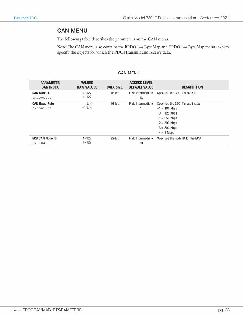
CAN MENUThe following table describes the parameters on the CAN menu.
Note: The CAN menu also contains the RPDO 1–4 Byte Map and TPDO 1–4 Byte Map menus, which specify the objects for which the PDOs transmit and receive data.
CAN MENU
PARAMETERCAN INDEX
VALUESRAW VALUES DATA SIZE
ACCESS LEVELDEFAULT VALUE DESCRIPTION
CAN Node ID0x2000:01
1–1271–127
16-bit Field Intermediate46
Specifies the 3301T’s node ID.
CAN Baud Rate0x2001:01
–1 to 4–1 to 4
16-bit Field Intermediate1
Specifies the 3301T’s baud rate:–1 = 100 Kbps 0 = 125 Kbps 1 = 250 Kbps 2 = 500 Kbps 3 = 800 Kbps 4 = 1 Mbps
ECS CAN Node ID0x3104:00
1–1271–127
32-bit Field Intermediate70
Specifies the node ID for the ECS.
4 — PROGRAMMABLE PARAMETERS
Curtis Model 3301T Digital Instrumentation – September 2021 Return to TOC
pg. 34
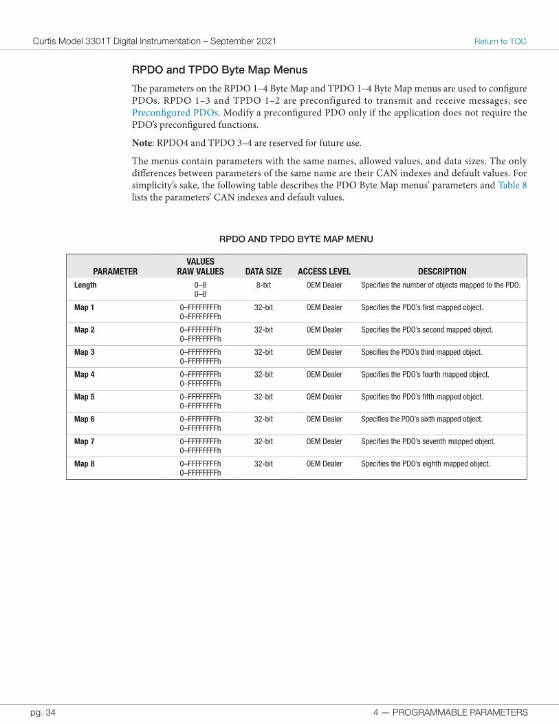
RPDO and TPDO Byte Map Menus
The parameters on the RPDO 1–4 Byte Map and TPDO 1–4 Byte Map menus are used to configure PDOs. RPDO 1–3 and TPDO 1–2 are preconfigured to transmit and receive messages; see Preconfigured PDOs. Modify a preconfigured PDO only if the application does not require the PDO’s preconfigured functions.
Note: RPDO4 and TPDO 3–4 are reserved for future use.
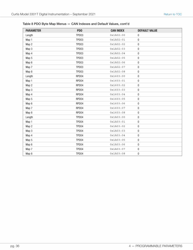
The menus contain parameters with the same names, allowed values, and data sizes. The only differences between parameters of the same name are their CAN indexes and default values. For simplicity’s sake, the following table describes the PDO Byte Map menus’ parameters and Table 8 lists the parameters’ CAN indexes and default values.
RPDO AND TPDO BYTE MAP MENU
PARAMETERVALUES
RAW VALUES DATA SIZE ACCESS LEVEL DESCRIPTIONLength 0–8
0–88-bit OEM Dealer Specifies the number of objects mapped to the PDO.
Map 1 0–FFFFFFFFh0–FFFFFFFFh
32-bit OEM Dealer Specifies the PDO’s first mapped object.
Map 2 0–FFFFFFFFh0–FFFFFFFFh
32-bit OEM Dealer Specifies the PDO’s second mapped object.
Map 3 0–FFFFFFFFh0–FFFFFFFFh
32-bit OEM Dealer Specifies the PDO’s third mapped object.
Map 4 0–FFFFFFFFh0–FFFFFFFFh
32-bit OEM Dealer Specifies the PDO’s fourth mapped object.
Map 5 0–FFFFFFFFh0–FFFFFFFFh
32-bit OEM Dealer Specifies the PDO’s fifth mapped object.
Map 6 0–FFFFFFFFh0–FFFFFFFFh
32-bit OEM Dealer Specifies the PDO’s sixth mapped object.
Map 7 0–FFFFFFFFh0–FFFFFFFFh
32-bit OEM Dealer Specifies the PDO’s seventh mapped object.
Map 8 0–FFFFFFFFh0–FFFFFFFFh
32-bit OEM Dealer Specifies the PDO’s eighth mapped object.
4 — PROGRAMMABLE PARAMETERS pg. 35
Return to TOC Curtis Model 3301T Digital Instrumentation – September 2021
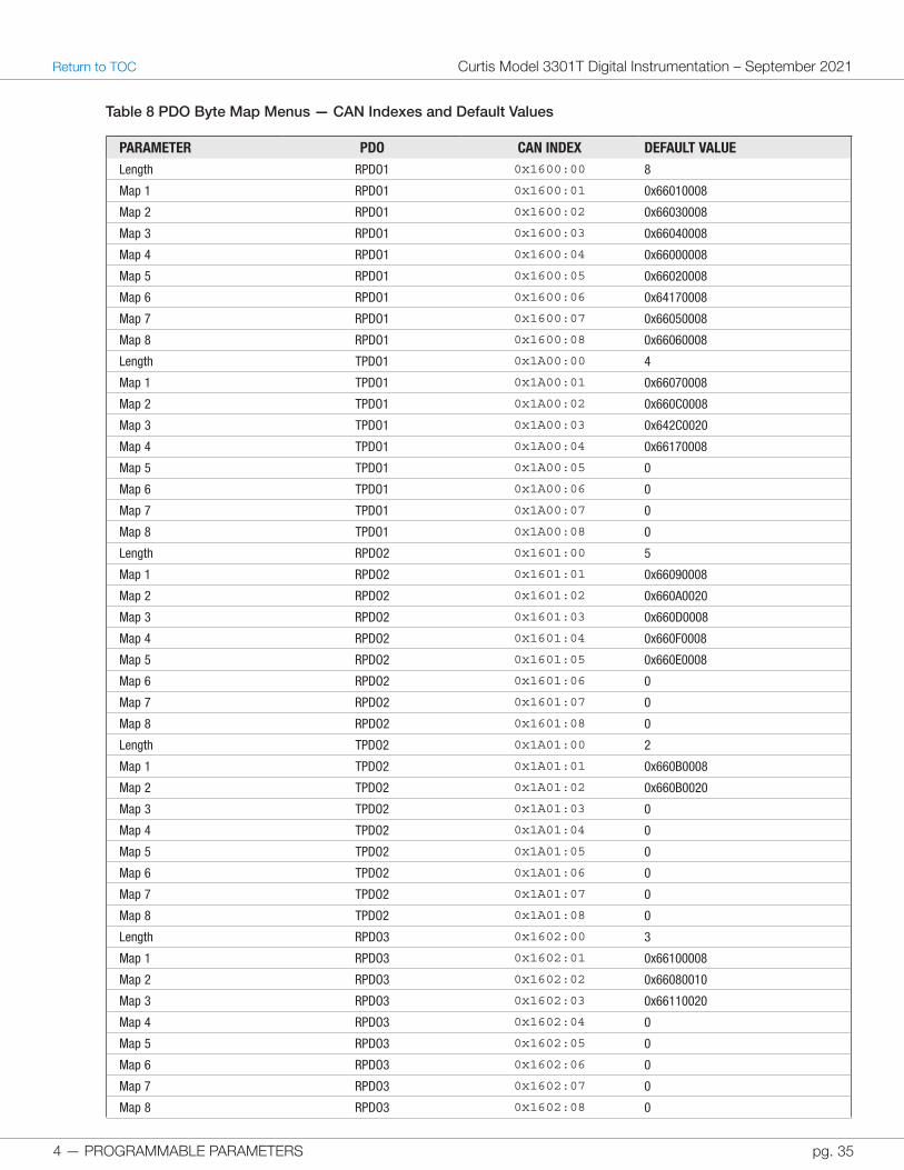
Table 8 PDO Byte Map Menus — CAN Indexes and Default Values
PARAMETER PDO CAN INDEX DEFAULT VALUELength RPDO1 0x1600:00 8
Map 1 RPDO1 0x1600:01 0x66010008
Map 2 RPDO1 0x1600:02 0x66030008
Map 3 RPDO1 0x1600:03 0x66040008
Map 4 RPDO1 0x1600:04 0x66000008
Map 5 RPDO1 0x1600:05 0x66020008
Map 6 RPDO1 0x1600:06 0x64170008
Map 7 RPDO1 0x1600:07 0x66050008
Map 8 RPDO1 0x1600:08 0x66060008
Length TPDO1 0x1A00:00 4
Map 1 TPDO1 0x1A00:01 0x66070008
Map 2 TPDO1 0x1A00:02 0x660C0008
Map 3 TPDO1 0x1A00:03 0x642C0020
Map 4 TPDO1 0x1A00:04 0x66170008
Map 5 TPDO1 0x1A00:05 0
Map 6 TPDO1 0x1A00:06 0
Map 7 TPDO1 0x1A00:07 0
Map 8 TPDO1 0x1A00:08 0
Length RPDO2 0x1601:00 5
Map 1 RPDO2 0x1601:01 0x66090008
Map 2 RPDO2 0x1601:02 0x660A0020
Map 3 RPDO2 0x1601:03 0x660D0008
Map 4 RPDO2 0x1601:04 0x660F0008
Map 5 RPDO2 0x1601:05 0x660E0008
Map 6 RPDO2 0x1601:06 0
Map 7 RPDO2 0x1601:07 0
Map 8 RPDO2 0x1601:08 0
Length TPDO2 0x1A01:00 2
Map 1 TPDO2 0x1A01:01 0x660B0008
Map 2 TPDO2 0x1A01:02 0x660B0020
Map 3 TPDO2 0x1A01:03 0
Map 4 TPDO2 0x1A01:04 0
Map 5 TPDO2 0x1A01:05 0
Map 6 TPDO2 0x1A01:06 0
Map 7 TPDO2 0x1A01:07 0
Map 8 TPDO2 0x1A01:08 0
Length RPDO3 0x1602:00 3
Map 1 RPDO3 0x1602:01 0x66100008
Map 2 RPDO3 0x1602:02 0x66080010
Map 3 RPDO3 0x1602:03 0x66110020
Map 4 RPDO3 0x1602:04 0
Map 5 RPDO3 0x1602:05 0
Map 6 RPDO3 0x1602:06 0
Map 7 RPDO3 0x1602:07 0
Map 8 RPDO3 0x1602:08 0
4 — PROGRAMMABLE PARAMETERS
Curtis Model 3301T Digital Instrumentation – September 2021 Return to TOC
pg. 36
PARAMETER PDO CAN INDEX DEFAULT VALUELength TPDO3 0x1A02:00 0
Map 1 TPDO3 0x1A02:01 0
Map 2 TPDO3 0x1A02:02 0
Map 3 TPDO3 0x1A02:03 0
Map 4 TPDO3 0x1A02:04 0
Map 5 TPDO3 0x1A02:05 0
Map 6 TPDO3 0x1A02:06 0
Map 7 TPDO3 0x1A02:07 0
Map 8 TPDO3 0x1A02:08 0
Length RPDO4 0x1603:00 0
Map 1 RPDO4 0x1603:01 0
Map 2 RPDO4 0x1603:02 0
Map 3 RPDO4 0x1603:03 0
Map 4 RPDO4 0x1603:04 0
Map 5 RPDO4 0x1603:05 0
Map 6 RPDO4 0x1603:06 0
Map 7 RPDO4 0x1603:07 0
Map 8 RPDO4 0x1603:08 0
Length TPDO4 0x1A03:00 0
Map 1 TPDO4 0x1A03:01 0
Map 2 TPDO4 0x1A03:02 0
Map 3 TPDO4 0x1A03:03 0
Map 4 TPDO4 0x1A03:04 0
Map 5 TPDO4 0x1A03:05 0
Map 6 TPDO4 0x1A03:06 0
Map 7 TPDO4 0x1A03:07 0
Map 8 TPDO4 0x1A03:08 0
Table 8 PDO Byte Map Menus — CAN Indexes and Default Values, cont’d
4 — PROGRAMMABLE PARAMETERS pg. 37
Return to TOC Curtis Model 3301T Digital Instrumentation – September 2021
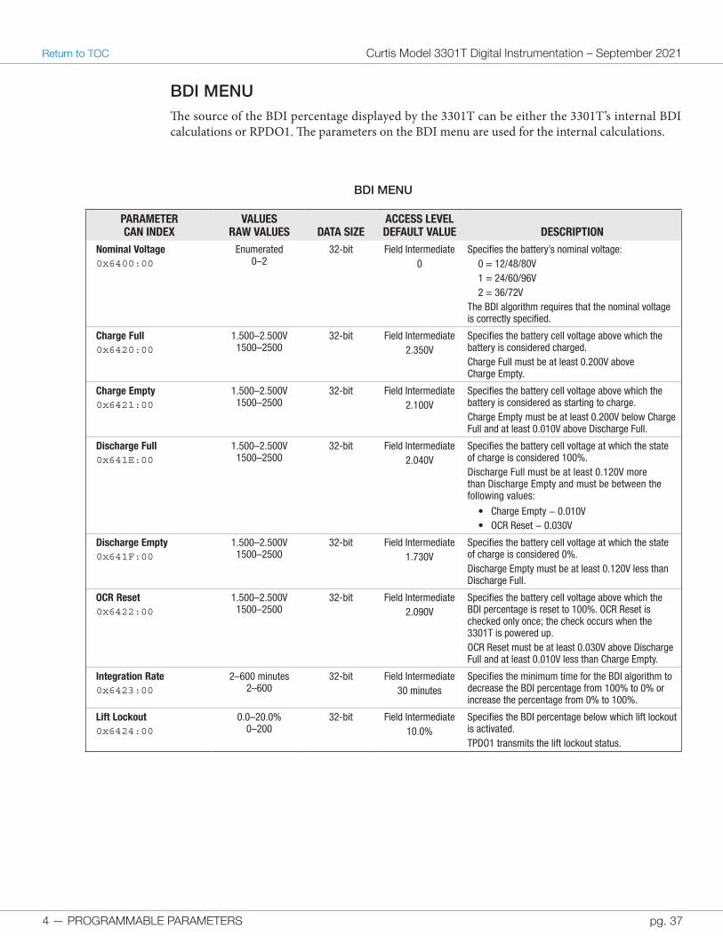
BDI MENUThe source of the BDI percentage displayed by the 3301T can be either the 3301T’s internal BDI calculations or RPDO1. The parameters on the BDI menu are used for the internal calculations.
BDI MENU
PARAMETERCAN INDEX
VALUESRAW VALUES DATA SIZE
ACCESS LEVELDEFAULT VALUE DESCRIPTION
Nominal Voltage0x6400:00
Enumerated0–2
32-bit Field Intermediate0
Specifies the battery’s nominal voltage:0 = 12/48/80V1 = 24/60/96V2 = 36/72V
The BDI algorithm requires that the nominal voltage is correctly specified.
Charge Full0x6420:00
1.500–2.500V1500–2500
32-bit Field Intermediate2.350V
Specifies the battery cell voltage above which the battery is considered charged.Charge Full must be at least 0.200V above Charge Empty.
Charge Empty0x6421:00
1.500–2.500V1500–2500
32-bit Field Intermediate2.100V
Specifies the battery cell voltage above which the battery is considered as starting to charge.Charge Empty must be at least 0.200V below Charge Full and at least 0.010V above Discharge Full.
Discharge Full0x641E:00
1.500–2.500V1500–2500
32-bit Field Intermediate2.040V
Specifies the battery cell voltage at which the state of charge is considered 100%.Discharge Full must be at least 0.120V more than Discharge Empty and must be between the following values:
• Charge Empty − 0.010V• OCR Reset − 0.030V
Discharge Empty0x641F:00
1.500–2.500V1500–2500
32-bit Field Intermediate1.730V
Specifies the battery cell voltage at which the state of charge is considered 0%.Discharge Empty must be at least 0.120V less than Discharge Full.
OCR Reset0x6422:00
1.500–2.500V1500–2500
32-bit Field Intermediate2.090V
Specifies the battery cell voltage above which the BDI percentage is reset to 100%. OCR Reset is checked only once; the check occurs when the 3301T is powered up.OCR Reset must be at least 0.030V above Discharge Full and at least 0.010V less than Charge Empty.
Integration Rate0x6423:00
2–600 minutes2–600
32-bit Field Intermediate30 minutes
Specifies the minimum time for the BDI algorithm to decrease the BDI percentage from 100% to 0% or increase the percentage from 0% to 100%.
Lift Lockout0x6424:00
0.0–20.0%0–200
32-bit Field Intermediate10.0%
Specifies the BDI percentage below which lift lockout is activated.TPDO1 transmits the lift lockout status.
4 — PROGRAMMABLE PARAMETERS
Curtis Model 3301T Digital Instrumentation – September 2021 Return to TOC
pg. 38
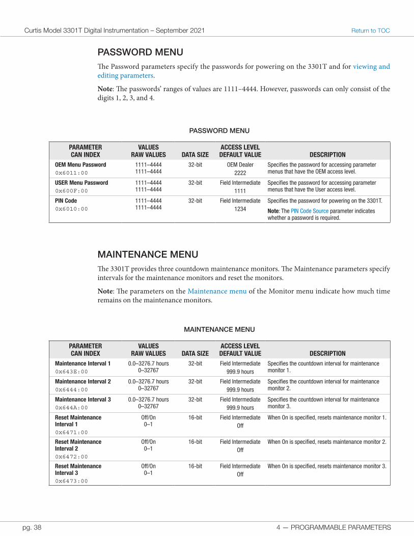
PASSWORD MENUThe Password parameters specify the passwords for powering on the 3301T and for viewing and editing parameters.
Note: The passwords’ ranges of values are 1111–4444. However, passwords can only consist of the digits 1, 2, 3, and 4.
PASSWORD MENU
PARAMETERCAN INDEX
VALUESRAW VALUES DATA SIZE
ACCESS LEVELDEFAULT VALUE DESCRIPTION
OEM Menu Password0x6011:00
1111–44441111–4444
32-bit OEM Dealer2222
Specifies the password for accessing parameter menus that have the OEM access level.
USER Menu Password0x600F:00
1111–44441111–4444
32-bit Field Intermediate1111
Specifies the password for accessing parameter menus that have the User access level.
PIN Code0x6010:00
1111–44441111–4444
32-bit Field Intermediate1234
Specifies the password for powering on the 3301T.
Note: The PIN Code Source parameter indicates whether a password is required.
MAINTENANCE MENUThe 3301T provides three countdown maintenance monitors. The Maintenance parameters specify intervals for the maintenance monitors and reset the monitors.
Note: The parameters on the Maintenance menu of the Monitor menu indicate how much time remains on the maintenance monitors.
MAINTENANCE MENU
PARAMETERCAN INDEX
VALUESRAW VALUES DATA SIZE
ACCESS LEVELDEFAULT VALUE DESCRIPTION
Maintenance Interval 10x643E:00
0.0–3276.7 hours0–32767
32-bit Field Intermediate999.9 hours
Specifies the countdown interval for maintenance monitor 1.
Maintenance Interval 20x6444:00
0.0–3276.7 hours0–32767
32-bit Field Intermediate999.9 hours
Specifies the countdown interval for maintenance monitor 2.
Maintenance Interval 30x644A:00
0.0–3276.7 hours0–32767
32-bit Field Intermediate999.9 hours
Specifies the countdown interval for maintenance monitor 3.
Reset Maintenance Interval 10x6471:00
Off/On0–1
16-bit Field IntermediateOff
When On is specified, resets maintenance monitor 1.
Reset Maintenance Interval 20x6472:00
Off/On0–1
16-bit Field IntermediateOff
When On is specified, resets maintenance monitor 2.
Reset Maintenance Interval 30x6473:00
Off/On0–1
16-bit Field IntermediateOff
When On is specified, resets maintenance monitor 3.
4 — PROGRAMMABLE PARAMETERS pg. 39
Return to TOC Curtis Model 3301T Digital Instrumentation – September 2021
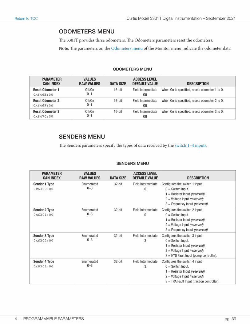
ODOMETERS MENUThe 3301T provides three odometers. The Odometers parameters reset the odometers.
Note: The parameters on the Odometers menu of the Monitor menu indicate the odometer data.
ODOMETERS MENU
PARAMETERCAN INDEX
VALUESRAW VALUES DATA SIZE
ACCESS LEVELDEFAULT VALUE DESCRIPTION
Reset Odometer 10x646E:00
Off/On0–1
16-bit Field IntermediateOff
When On is specified, resets odometer 1 to 0.
Reset Odometer 20x646F:00
Off/On0–1
16-bit Field IntermediateOff
When On is specified, resets odometer 2 to 0.
Reset Odometer 30x6470:00
Off/On0–1
16-bit Field IntermediateOff
When On is specified, resets odometer 3 to 0.
SENDERS MENUThe Senders parameters specify the types of data received by the switch 1–4 inputs.
SENDERS MENU
PARAMETERCAN INDEX
VALUESRAW VALUES DATA SIZE
ACCESS LEVELDEFAULT VALUE DESCRIPTION
Sender 1 Type0x6300:00
Enumerated0–3
32-bit Field Intermediate0
Configures the switch 1 input:0 = Switch Input.1 = Resistor Input (reserved).2 = Voltage Input (reserved).3 = Frequency Input (reserved).
Sender 2 Type0x6301:00
Enumerated0–3
32-bit Field Intermediate0
Configures the switch 2 input:0 = Switch Input.1 = Resistor Input (reserved).2 = Voltage Input (reserved).3 = Frequency Input (reserved).
Sender 3 Type0x6302:00
Enumerated0–3
32-bit Field Intermediate3
Configures the switch 3 input:0 = Switch Input.1 = Resistor Input (reserved).2 = Voltage Input (reserved).3 = HYD Fault Input (pump controller).
Sender 4 Type0x6303:00
Enumerated0–3
32-bit Field Intermediate3
Configures the switch 4 input:0 = Switch Input.1 = Resistor Input (reserved).2 = Voltage Input (reserved).3 = TRA Fault Input (traction controller).
4 — PROGRAMMABLE PARAMETERS
Curtis Model 3301T Digital Instrumentation – September 2021 Return to TOC
pg. 40
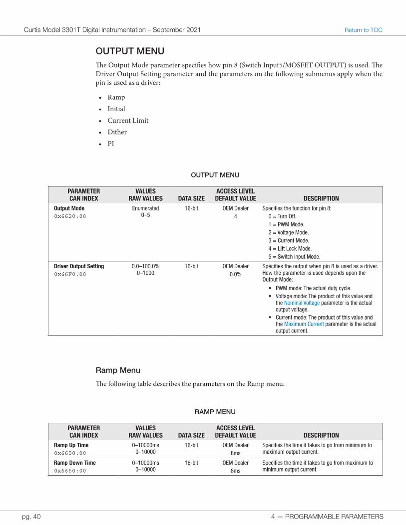
OUTPUT MENUThe Output Mode parameter specifies how pin 8 (Switch Input5/MOSFET OUTPUT) is used. The Driver Output Setting parameter and the parameters on the following submenus apply when the pin is used as a driver:
• Ramp• Initial• Current Limit• Dither• PI
OUTPUT MENU
PARAMETERCAN INDEX
VALUESRAW VALUES DATA SIZE
ACCESS LEVELDEFAULT VALUE DESCRIPTION
Output Mode0x6620:00
Enumerated0–5
16-bit OEM Dealer4
Specifies the function for pin 8:0 = Turn Off.1 = PWM Mode.2 = Voltage Mode.3 = Current Mode.4 = Lift Lock Mode.5 = Switch Input Mode.
Driver Output Setting0x66F0:00
0.0–100.0%0–1000
16-bit OEM Dealer0.0%
Specifies the output when pin 8 is used as a driver. How the parameter is used depends upon the Output Mode:
• PWM mode: The actual duty cycle.• Voltage mode: The product of this value and
the Nominal Voltage parameter is the actual output voltage.
• Current mode: The product of this value and the Maximum Current parameter is the actual output current.
Ramp Menu
The following table describes the parameters on the Ramp menu.
RAMP MENU
PARAMETERCAN INDEX
VALUESRAW VALUES DATA SIZE
ACCESS LEVELDEFAULT VALUE DESCRIPTION
Ramp Up Time0x6650:00
0–10000ms0–10000
16-bit OEM Dealer8ms
Specifies the time it takes to go from minimum to maximum output current.
Ramp Down Time0x6660:00
0–10000ms0–10000
16-bit OEM Dealer8ms
Specifies the time it takes to go from maximum to minimum output current.
4 — PROGRAMMABLE PARAMETERS pg. 41
Return to TOC Curtis Model 3301T Digital Instrumentation – September 2021
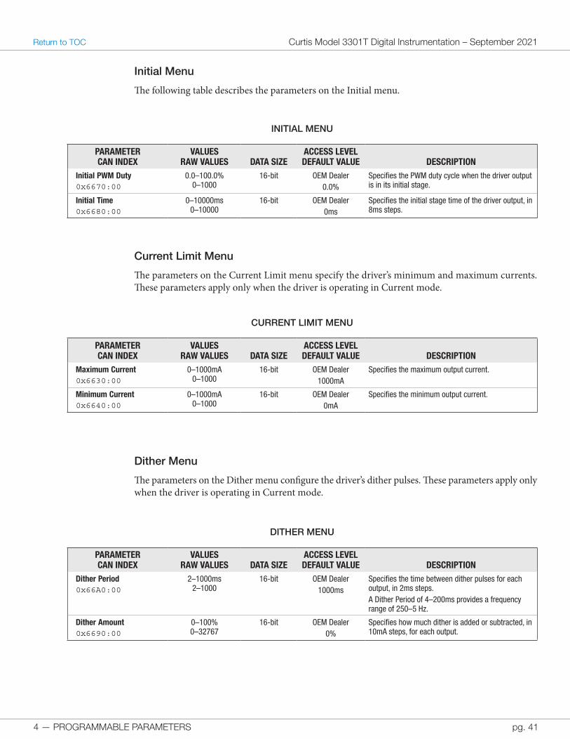
Initial Menu
The following table describes the parameters on the Initial menu.
INITIAL MENU
PARAMETERCAN INDEX
VALUESRAW VALUES DATA SIZE
ACCESS LEVELDEFAULT VALUE DESCRIPTION
Initial PWM Duty0x6670:00
0.0–100.0%0–1000
16-bit OEM Dealer0.0%
Specifies the PWM duty cycle when the driver output is in its initial stage.
Initial Time0x6680:00
0–10000ms0–10000
16-bit OEM Dealer0ms
Specifies the initial stage time of the driver output, in 8ms steps.
Current Limit Menu
The parameters on the Current Limit menu specify the driver’s minimum and maximum currents. These parameters apply only when the driver is operating in Current mode.
CURRENT LIMIT MENU
PARAMETERCAN INDEX
VALUESRAW VALUES DATA SIZE
ACCESS LEVELDEFAULT VALUE DESCRIPTION
Maximum Current0x6630:00
0–1000mA0–1000
16-bit OEM Dealer1000mA
Specifies the maximum output current.
Minimum Current0x6640:00
0–1000mA0–1000
16-bit OEM Dealer0mA
Specifies the minimum output current.
Dither Menu
The parameters on the Dither menu configure the driver’s dither pulses. These parameters apply only when the driver is operating in Current mode.
DITHER MENU
PARAMETERCAN INDEX
VALUESRAW VALUES DATA SIZE
ACCESS LEVELDEFAULT VALUE DESCRIPTION
Dither Period0x66A0:00
2–1000ms2–1000
16-bit OEM Dealer1000ms
Specifies the time between dither pulses for each output, in 2ms steps.A Dither Period of 4–200ms provides a frequency range of 250–5 Hz.
Dither Amount0x6690:00
0–100%0–32767
16-bit OEM Dealer0%
Specifies how much dither is added or subtracted, in 10mA steps, for each output.
4 — PROGRAMMABLE PARAMETERS
Curtis Model 3301T Digital Instrumentation – September 2021 Return to TOC
pg. 42
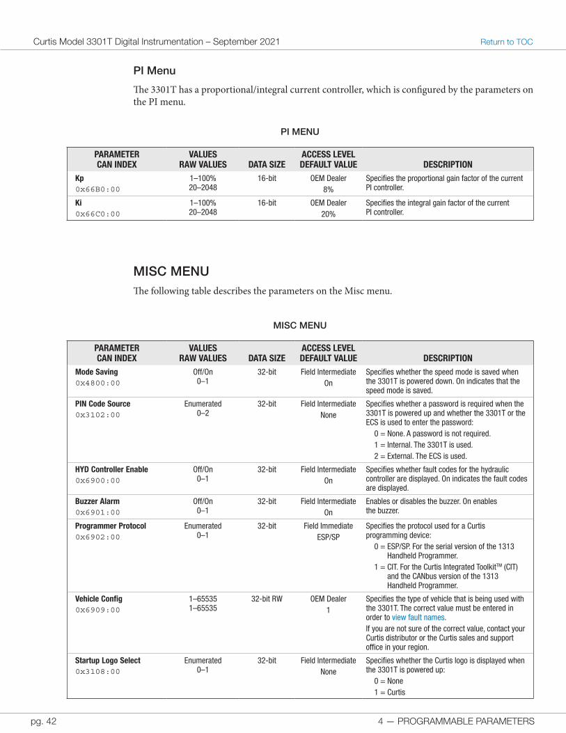
PI Menu
The 3301T has a proportional/integral current controller, which is configured by the parameters on the PI menu.
PI MENU
PARAMETERCAN INDEX
VALUESRAW VALUES DATA SIZE
ACCESS LEVELDEFAULT VALUE DESCRIPTION
Kp0x66B0:00
1–100%20–2048
16-bit OEM Dealer8%
Specifies the proportional gain factor of the current PI controller.
Ki0x66C0:00
1–100%20–2048
16-bit OEM Dealer20%
Specifies the integral gain factor of the current PI controller.
MISC MENUThe following table describes the parameters on the Misc menu.
MISC MENU
PARAMETERCAN INDEX
VALUESRAW VALUES DATA SIZE
ACCESS LEVELDEFAULT VALUE DESCRIPTION
Mode Saving0x4800:00
Off/On0–1
32-bit Field IntermediateOn
Specifies whether the speed mode is saved when the 3301T is powered down. On indicates that the speed mode is saved.
PIN Code Source0x3102:00
Enumerated0–2
32-bit Field IntermediateNone
Specifies whether a password is required when the 3301T is powered up and whether the 3301T or the ECS is used to enter the password:
0 = None. A password is not required.1 = Internal. The 3301T is used.2 = External. The ECS is used.
HYD Controller Enable0x6900:00
Off/On0–1
32-bit Field IntermediateOn
Specifies whether fault codes for the hydraulic controller are displayed. On indicates the fault codes are displayed.
Buzzer Alarm0x6901:00
Off/On0–1
32-bit Field IntermediateOn
Enables or disables the buzzer. On enables the buzzer.
Programmer Protocol0x6902:00
Enumerated0–1
32-bit Field ImmediateESP/SP
Specifies the protocol used for a Curtis programming device:
0 = ESP/SP. For the serial version of the 1313 Handheld Programmer.
1 = CIT. For the Curtis Integrated ToolkitTM (CIT) and the CANbus version of the 1313 Handheld Programmer.
Vehicle Config0x6909:00
1–655351–65535
32-bit RW OEM Dealer1
Specifies the type of vehicle that is being used with the 3301T. The correct value must be entered in order to view fault names.If you are not sure of the correct value, contact your Curtis distributor or the Curtis sales and support office in your region.
Startup Logo Select0x3108:00
Enumerated0–1
32-bit Field IntermediateNone
Specifies whether the Curtis logo is displayed when the 3301T is powered up:
0 = None1 = Curtis
5 — MONITOR PARAMETERS pg. 43
Return to TOC Curtis Model 3301T Digital Instrumentation – September 2021
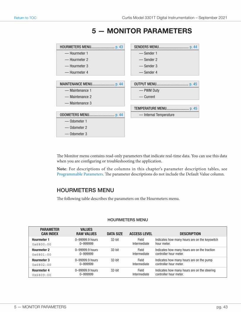
5 — MONITOR PARAMETERS
HOURMETERS MENU......................... p. 43
— Hourmeter 1
— Hourmeter 2
— Hourmeter 3
— Hourmeter 4
MAINTENANCE MENU........................ p. 44
— Maintenance 1
— Maintenance 2
— Maintenance 3
ODOMETERS MENU........................... p. 44
— Odometer 1
— Odometer 2
— Odometer 3
SENDERS MENU................................ p. 44
— Sender 1
— Sender 2
— Sender 3
— Sender 4
OUTPUT MENU.................................. p. 45
— PWM Duty
— Current
TEMPERATURE MENU........................ p. 45
— Internal Temperature
The Monitor menu contains read-only parameters that indicate real-time data. You can use this data when you are configuring or troubleshooting the application.
Note: For descriptions of the columns in this chapter’s parameter description tables, see Programmable Parameters. The parameter descriptions do not include the Default Value column.
HOURMETERS MENUThe following table describes the parameters on the Hourmeters menu.
HOURMETERS MENU
PARAMETERCAN INDEX
VALUESRAW VALUES DATA SIZE ACCESS LEVEL DESCRIPTION
Hourmeter 10x6800:00
0–99999.9 hours0–999999
32-bit Field Intermediate
Indicates how many hours are on the keyswitch hour meter.
Hourmeter 20x6801:00
0–99999.9 hours0–999999
32-bit Field Intermediate
Indicates how many hours are on the traction controller hour meter.
Hourmeter 30x6802:00
0–99999.9 hours0–999999
32-bit Field Intermediate
Indicates how many hours are on the pump controller hour meter.
Hourmeter 40x6809:00
0–99999.9 hours0–999999
32-bit Field Intermediate
Indicates how many hours are on the steering controller hour meter.
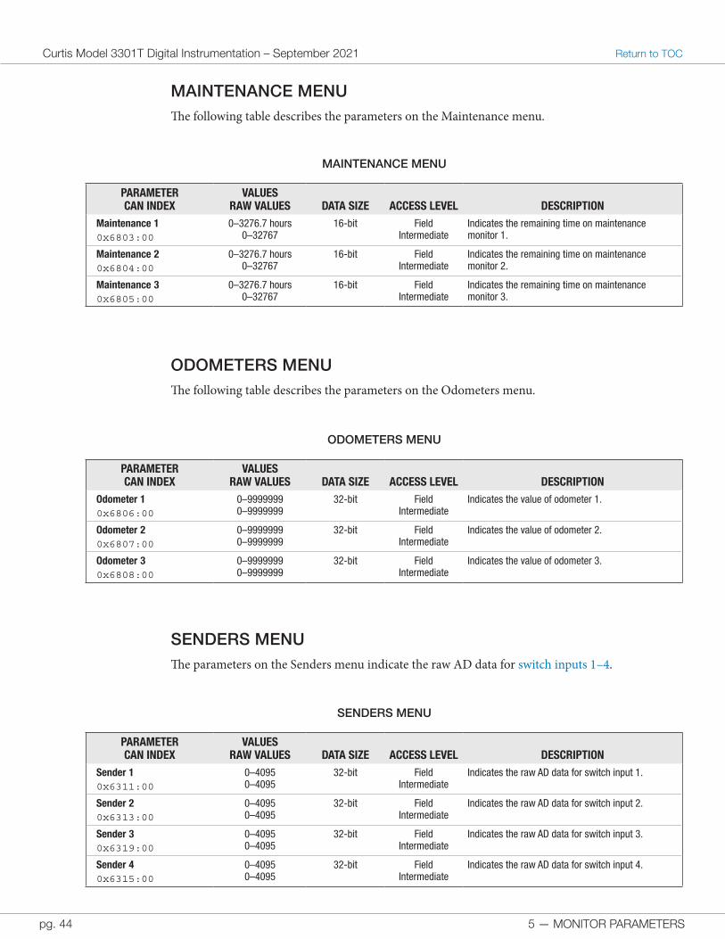
5 — MONITOR PARAMETERS
Curtis Model 3301T Digital Instrumentation – September 2021 Return to TOC
pg. 44
MAINTENANCE MENUThe following table describes the parameters on the Maintenance menu.
MAINTENANCE MENU
PARAMETERCAN INDEX
VALUESRAW VALUES DATA SIZE ACCESS LEVEL DESCRIPTION
Maintenance 10x6803:00
0–3276.7 hours0–32767
16-bit Field Intermediate
Indicates the remaining time on maintenance monitor 1.
Maintenance 20x6804:00
0–3276.7 hours0–32767
16-bit Field Intermediate
Indicates the remaining time on maintenance monitor 2.
Maintenance 30x6805:00
0–3276.7 hours0–32767
16-bit Field Intermediate
Indicates the remaining time on maintenance monitor 3.
SENDERS MENUThe parameters on the Senders menu indicate the raw AD data for switch inputs 1–4.
SENDERS MENU
PARAMETERCAN INDEX
VALUESRAW VALUES DATA SIZE ACCESS LEVEL DESCRIPTION
Sender 10x6311:00
0–40950–4095
32-bit Field Intermediate
Indicates the raw AD data for switch input 1.
Sender 20x6313:00
0–40950–4095
32-bit Field Intermediate
Indicates the raw AD data for switch input 2.
Sender 30x6319:00
0–40950–4095
32-bit Field Intermediate
Indicates the raw AD data for switch input 3.
Sender 40x6315:00
0–40950–4095
32-bit Field Intermediate
Indicates the raw AD data for switch input 4.
ODOMETERS MENUThe following table describes the parameters on the Odometers menu.
ODOMETERS MENU
PARAMETERCAN INDEX
VALUESRAW VALUES DATA SIZE ACCESS LEVEL DESCRIPTION
Odometer 10x6806:00
0–99999990–9999999
32-bit Field Intermediate
Indicates the value of odometer 1.
Odometer 20x6807:00
0–99999990–9999999
32-bit Field Intermediate
Indicates the value of odometer 2.
Odometer 30x6808:00
0–99999990–9999999
32-bit Field Intermediate
Indicates the value of odometer 3.
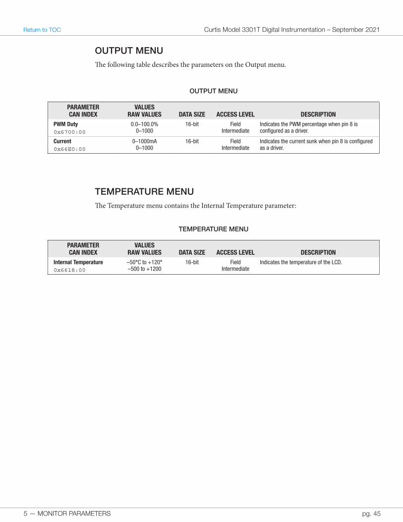
5 — MONITOR PARAMETERS pg. 45
Return to TOC Curtis Model 3301T Digital Instrumentation – September 2021
OUTPUT MENUThe following table describes the parameters on the Output menu.
OUTPUT MENU
PARAMETERCAN INDEX
VALUESRAW VALUES DATA SIZE ACCESS LEVEL DESCRIPTION
PWM Duty0x6700:00
0.0–100.0%0–1000
16-bit Field Intermediate
Indicates the PWM percentage when pin 8 is configured as a driver.
Current0x66E0:00
0–1000mA0–1000
16-bit Field Intermediate
Indicates the current sunk when pin 8 is configured as a driver.
TEMPERATURE MENUThe Temperature menu contains the Internal Temperature parameter:
TEMPERATURE MENU
PARAMETERCAN INDEX
VALUESRAW VALUES DATA SIZE ACCESS LEVEL DESCRIPTION
Internal Temperature 0x6618:00
–50°C to +120°–500 to +1200
16-bit Field Intermediate
Indicates the temperature of the LCD.
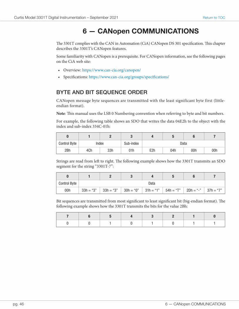
6 — CANopen COMMUNICATIONS
Curtis Model 3301T Digital Instrumentation – September 2021 Return to TOC
pg. 46
6 — CANopen COMMUNICATIONS
The 3301T complies with the CAN in Automation (CiA) CANopen DS 301 specification. This chapter describes the 3301T’s CANopen features.
Some familiarity with CANopen is a prerequisite. For CANopen information, see the following pages on the CiA web site:
• Overview: https://www.can-cia.org/canopen/• Specifications: https://www.can-cia.org/groups/specifications/
BYTE AND BIT SEQUENCE ORDERCANopen message byte sequences are transmitted with the least significant byte first (little-endian format).
Note: This manual uses the LSB 0 Numbering convention when referring to byte and bit numbers.
For example, the following table shows an SDO that writes the data 04E2h to the object with the index and sub-index 334C-01h:
0 1 2 3 4 5 6 7
Control Byte Index Sub-index Data
2Bh 4Ch 33h 01h E2h 04h 00h 00h
Strings are read from left to right. The following example shows how the 3301T transmits an SDO segment for the string “3301T-7”:
0 1 2 3 4 5 6 7
Control Byte Data
00h 33h = “3” 33h = “3” 30h = “0” 31h = “1” 54h = “T” 2Dh = “-” 37h = “7”
Bit sequences are transmitted from most significant to least significant bit (big-endian format). The following example shows how the 3301T transmits the bits for the value 2Bh:
7 6 5 4 3 2 1 0
0 0 1 0 1 0 1 1
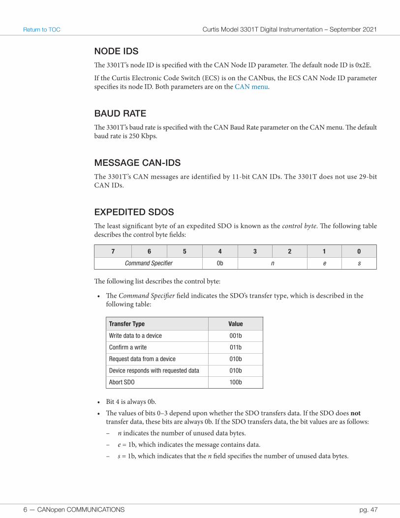
6 — CANopen COMMUNICATIONS pg. 47
Return to TOC Curtis Model 3301T Digital Instrumentation – September 2021
NODE IDSThe 3301T’s node ID is specified with the CAN Node ID parameter. The default node ID is 0x2E.
If the Curtis Electronic Code Switch (ECS) is on the CANbus, the ECS CAN Node ID parameter specifies its node ID. Both parameters are on the CAN menu.
BAUD RATEThe 3301T’s baud rate is specified with the CAN Baud Rate parameter on the CAN menu. The default baud rate is 250 Kbps.
MESSAGE CAN-IDSThe 3301T’s CAN messages are identified by 11-bit CAN IDs. The 3301T does not use 29-bit CAN IDs.
EXPEDITED SDOSThe least significant byte of an expedited SDO is known as the control byte. The following table describes the control byte fields:
7 6 5 4 3 2 1 0
Command Specifier 0b n e s
The following list describes the control byte:
• The Command Specifier field indicates the SDO’s transfer type, which is described in the following table:
Transfer Type Value
Write data to a device 001b
Confirm a write 011b
Request data from a device 010b
Device responds with requested data 010b
Abort SDO 100b
• Bit 4 is always 0b.• The values of bits 0–3 depend upon whether the SDO transfers data. If the SDO does not
transfer data, these bits are always 0b. If the SDO transfers data, the bit values are as follows: – n indicates the number of unused data bytes. – e = 1b, which indicates the message contains data. – s = 1b, which indicates that the n field specifies the number of unused data bytes.
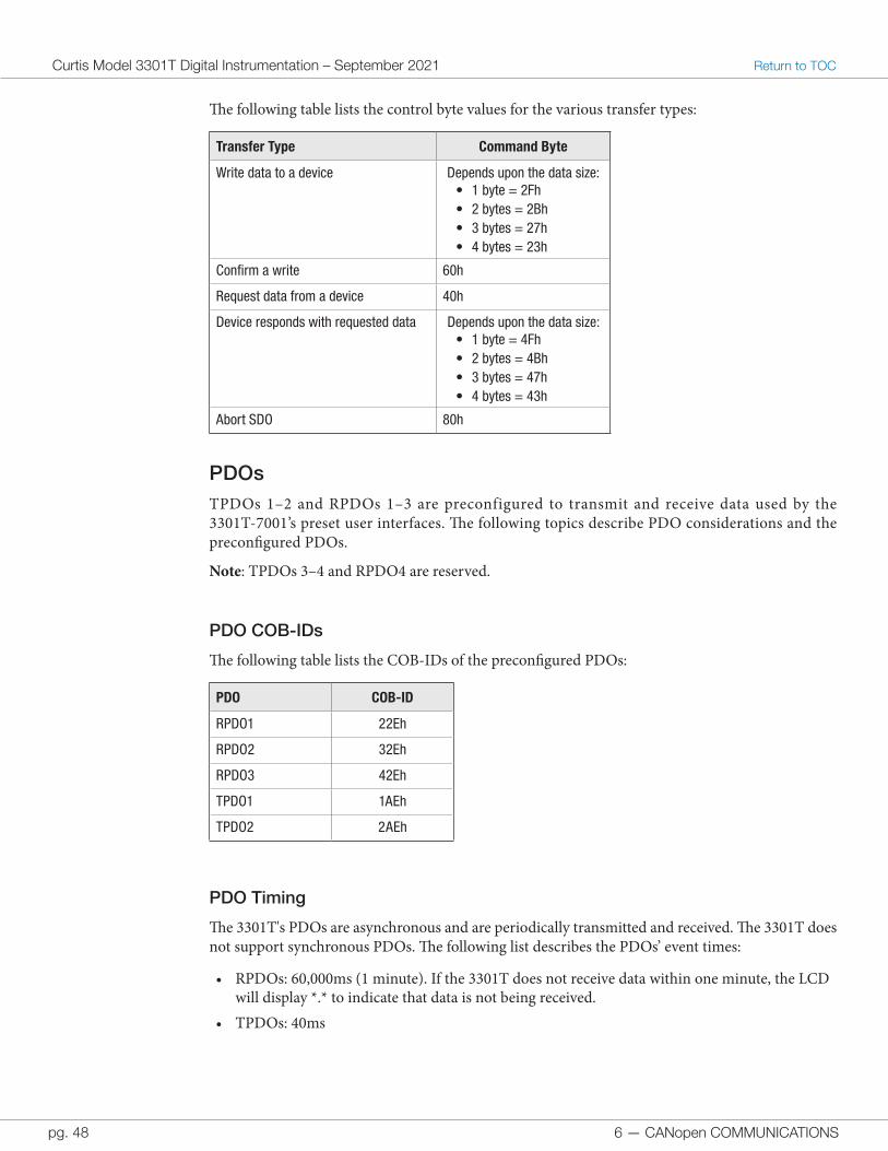
6 — CANopen COMMUNICATIONS
Curtis Model 3301T Digital Instrumentation – September 2021 Return to TOC
pg. 48
The following table lists the control byte values for the various transfer types:
Transfer Type Command Byte
Write data to a device Depends upon the data size:• 1 byte = 2Fh• 2 bytes = 2Bh• 3 bytes = 27h• 4 bytes = 23h
Confirm a write 60h
Request data from a device 40h
Device responds with requested data Depends upon the data size:• 1 byte = 4Fh• 2 bytes = 4Bh• 3 bytes = 47h• 4 bytes = 43h
Abort SDO 80h
PDOsTPDOs 1–2 and RPDOs 1–3 are preconfigured to transmit and receive data used by the 3301T-7001’s preset user interfaces. The following topics describe PDO considerations and the preconfigured PDOs.
Note: TPDOs 3–4 and RPDO4 are reserved.
PDO COB-IDs
The following table lists the COB-IDs of the preconfigured PDOs:
PDO COB-ID
RPDO1 22Eh
RPDO2 32Eh
RPDO3 42Eh
TPDO1 1AEh
TPDO2 2AEh
PDO Timing
The 3301T's PDOs are asynchronous and are periodically transmitted and received. The 3301T does not support synchronous PDOs. The following list describes the PDOs’ event times:
• RPDOs: 60,000ms (1 minute). If the 3301T does not receive data within one minute, the LCD will display *.* to indicate that data is not being received.
• TPDOs: 40ms
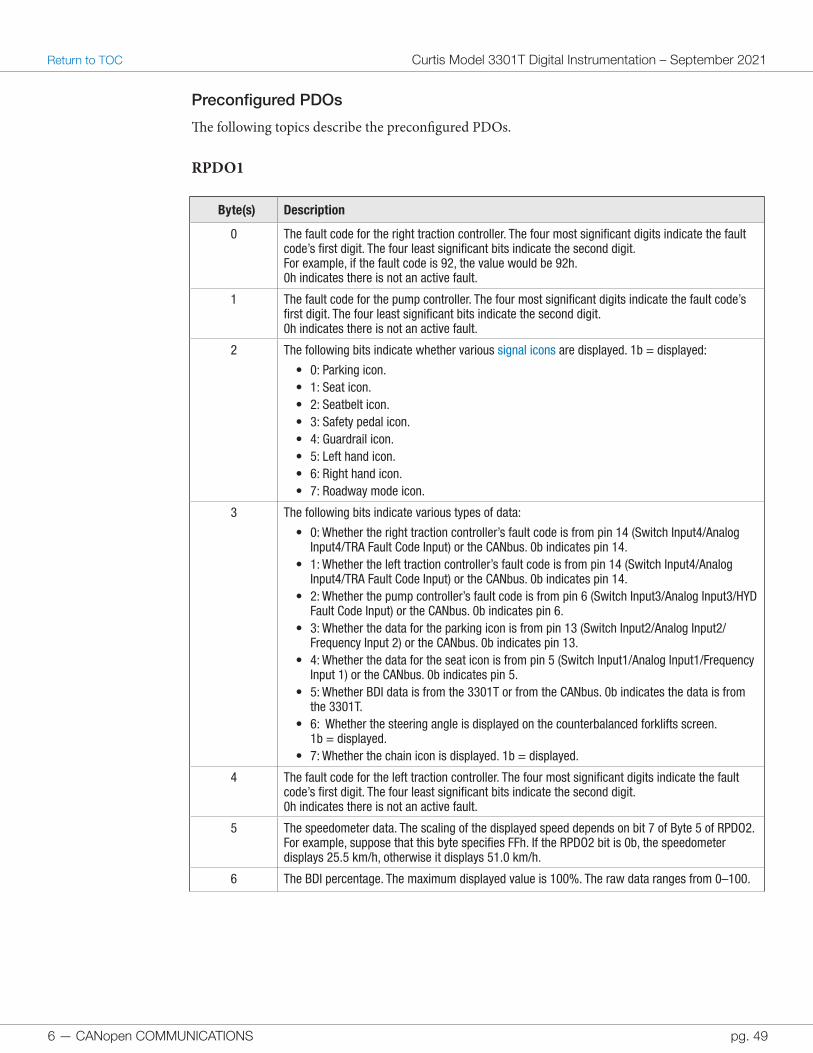
6 — CANopen COMMUNICATIONS pg. 49
Return to TOC Curtis Model 3301T Digital Instrumentation – September 2021
Preconfigured PDOs
The following topics describe the preconfigured PDOs.
RPDO1
Byte(s) Description
0 The fault code for the right traction controller. The four most significant digits indicate the fault code’s first digit. The four least significant bits indicate the second digit.For example, if the fault code is 92, the value would be 92h.0h indicates there is not an active fault.
1 The fault code for the pump controller. The four most significant digits indicate the fault code’s first digit. The four least significant bits indicate the second digit.0h indicates there is not an active fault.
2 The following bits indicate whether various signal icons are displayed. 1b = displayed:
• 0: Parking icon.• 1: Seat icon.• 2: Seatbelt icon.• 3: Safety pedal icon.• 4: Guardrail icon.• 5: Left hand icon.• 6: Right hand icon.• 7: Roadway mode icon.
3 The following bits indicate various types of data:
• 0: Whether the right traction controller’s fault code is from pin 14 (Switch Input4/Analog Input4/TRA Fault Code Input) or the CANbus. 0b indicates pin 14.
• 1: Whether the left traction controller’s fault code is from pin 14 (Switch Input4/Analog Input4/TRA Fault Code Input) or the CANbus. 0b indicates pin 14.
• 2: Whether the pump controller’s fault code is from pin 6 (Switch Input3/Analog Input3/HYD Fault Code Input) or the CANbus. 0b indicates pin 6.
• 3: Whether the data for the parking icon is from pin 13 (Switch Input2/Analog Input2/Frequency Input 2) or the CANbus. 0b indicates pin 13.
• 4: Whether the data for the seat icon is from pin 5 (Switch Input1/Analog Input1/Frequency Input 1) or the CANbus. 0b indicates pin 5.
• 5: Whether BDI data is from the 3301T or from the CANbus. 0b indicates the data is from the 3301T.
• 6: Whether the steering angle is displayed on the counterbalanced forklifts screen. 1b = displayed.
• 7: Whether the chain icon is displayed. 1b = displayed.
4 The fault code for the left traction controller. The four most significant digits indicate the fault code’s first digit. The four least significant bits indicate the second digit.0h indicates there is not an active fault.
5 The speedometer data. The scaling of the displayed speed depends on bit 7 of Byte 5 of RPDO2.For example, suppose that this byte specifies FFh. If the RPDO2 bit is 0b, the speedometer displays 25.5 km/h, otherwise it displays 51.0 km/h.
6 The BDI percentage. The maximum displayed value is 100%. The raw data ranges from 0–100.
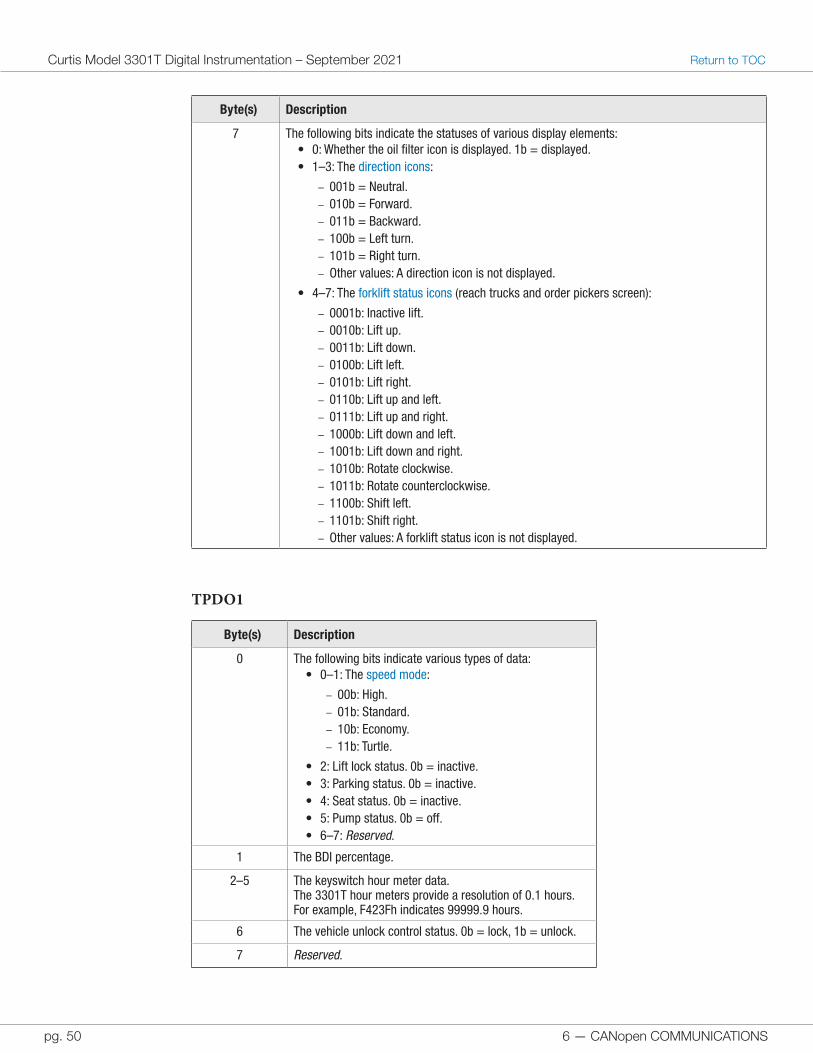
6 — CANopen COMMUNICATIONS
Curtis Model 3301T Digital Instrumentation – September 2021 Return to TOC
pg. 50
TPDO1
Byte(s) Description
0 The following bits indicate various types of data:• 0–1: The speed mode:
– 00b: High. – 01b: Standard. – 10b: Economy. – 11b: Turtle.
• 2: Lift lock status. 0b = inactive.• 3: Parking status. 0b = inactive.• 4: Seat status. 0b = inactive.• 5: Pump status. 0b = off.• 6–7: Reserved.
1 The BDI percentage.
2–5 The keyswitch hour meter data.The 3301T hour meters provide a resolution of 0.1 hours. For example, F423Fh indicates 99999.9 hours.
6 The vehicle unlock control status. 0b = lock, 1b = unlock.
7 Reserved.
Byte(s) Description
7 The following bits indicate the statuses of various display elements:• 0: Whether the oil filter icon is displayed. 1b = displayed.• 1–3: The direction icons:
– 001b = Neutral. – 010b = Forward. – 011b = Backward. – 100b = Left turn. – 101b = Right turn. – Other values: A direction icon is not displayed.
• 4–7: The forklift status icons (reach trucks and order pickers screen):
– 0001b: Inactive lift. – 0010b: Lift up. – 0011b: Lift down. – 0100b: Lift left. – 0101b: Lift right. – 0110b: Lift up and left. – 0111b: Lift up and right. – 1000b: Lift down and left. – 1001b: Lift down and right. – 1010b: Rotate clockwise. – 1011b: Rotate counterclockwise. – 1100b: Shift left. – 1101b: Shift right. – Other values: A forklift status icon is not displayed.
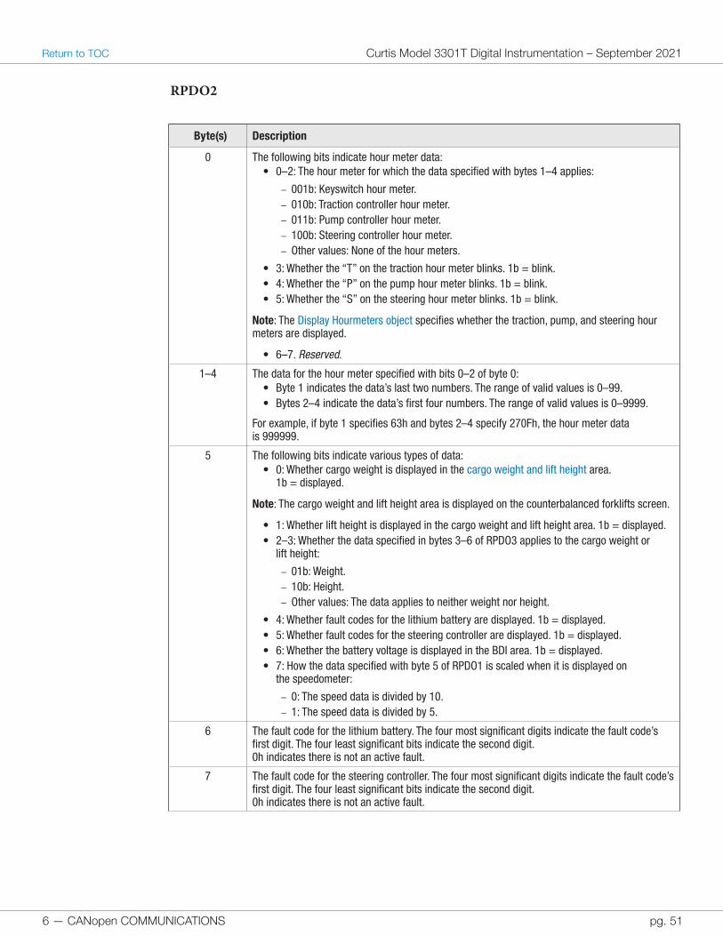
6 — CANopen COMMUNICATIONS pg. 51
Return to TOC Curtis Model 3301T Digital Instrumentation – September 2021
RPDO2
Byte(s) Description
0 The following bits indicate hour meter data:• 0–2: The hour meter for which the data specified with bytes 1–4 applies:
– 001b: Keyswitch hour meter. – 010b: Traction controller hour meter. – 011b: Pump controller hour meter. – 100b: Steering controller hour meter. – Other values: None of the hour meters.
• 3: Whether the “T” on the traction hour meter blinks. 1b = blink.• 4: Whether the “P” on the pump hour meter blinks. 1b = blink.• 5: Whether the “S” on the steering hour meter blinks. 1b = blink.
Note: The Display Hourmeters object specifies whether the traction, pump, and steering hour meters are displayed.
• 6–7. Reserved.
1–4 The data for the hour meter specified with bits 0–2 of byte 0:• Byte 1 indicates the data’s last two numbers. The range of valid values is 0–99.• Bytes 2–4 indicate the data’s first four numbers. The range of valid values is 0–9999.
For example, if byte 1 specifies 63h and bytes 2–4 specify 270Fh, the hour meter data is 999999.
5 The following bits indicate various types of data:• 0: Whether cargo weight is displayed in the cargo weight and lift height area.
1b = displayed.
Note: The cargo weight and lift height area is displayed on the counterbalanced forklifts screen.
• 1: Whether lift height is displayed in the cargo weight and lift height area. 1b = displayed.• 2–3: Whether the data specified in bytes 3–6 of RPDO3 applies to the cargo weight or
lift height:
– 01b: Weight. – 10b: Height. – Other values: The data applies to neither weight nor height.
• 4: Whether fault codes for the lithium battery are displayed. 1b = displayed.• 5: Whether fault codes for the steering controller are displayed. 1b = displayed.• 6: Whether the battery voltage is displayed in the BDI area. 1b = displayed.• 7: How the data specified with byte 5 of RPDO1 is scaled when it is displayed on
the speedometer:
– 0: The speed data is divided by 10. – 1: The speed data is divided by 5.
6 The fault code for the lithium battery. The four most significant digits indicate the fault code’s first digit. The four least significant bits indicate the second digit.0h indicates there is not an active fault.
7 The fault code for the steering controller. The four most significant digits indicate the fault code’s first digit. The four least significant bits indicate the second digit.0h indicates there is not an active fault.
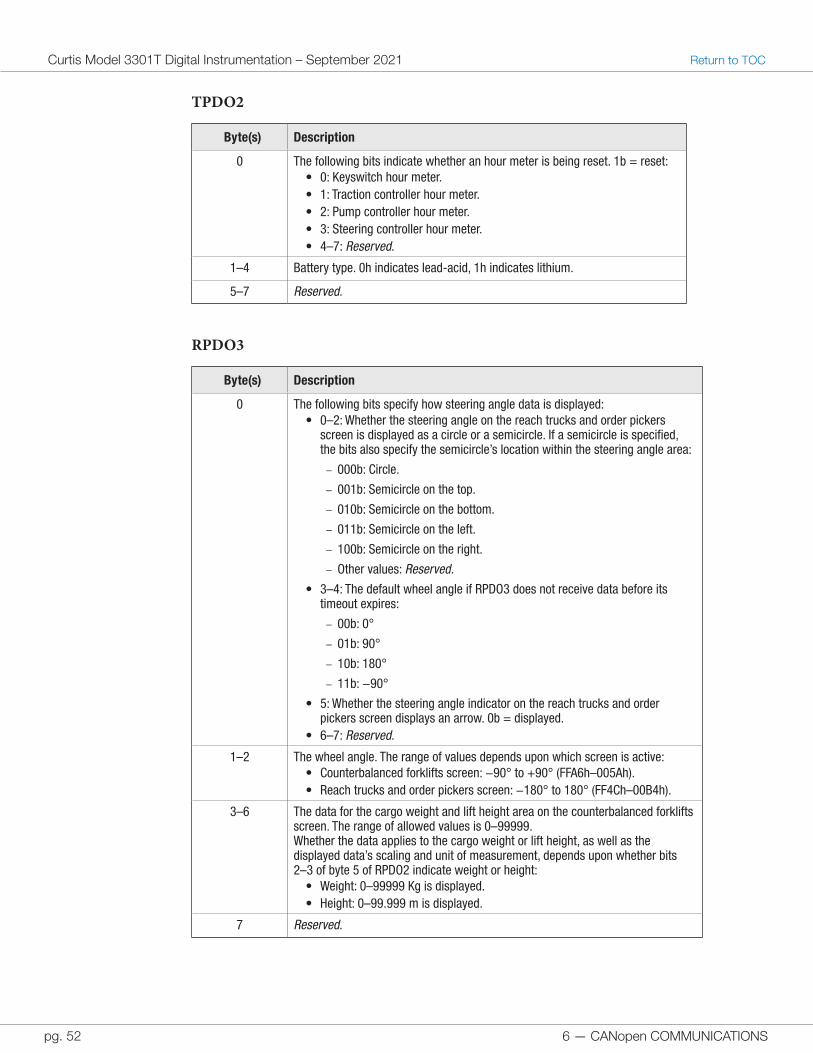
6 — CANopen COMMUNICATIONS
Curtis Model 3301T Digital Instrumentation – September 2021 Return to TOC
pg. 52
TPDO2
Byte(s) Description
0 The following bits indicate whether an hour meter is being reset. 1b = reset:• 0: Keyswitch hour meter.• 1: Traction controller hour meter.• 2: Pump controller hour meter.• 3: Steering controller hour meter.• 4–7: Reserved.
1–4 Battery type. 0h indicates lead-acid, 1h indicates lithium.
5–7 Reserved.
RPDO3
Byte(s) Description
0 The following bits specify how steering angle data is displayed:• 0–2: Whether the steering angle on the reach trucks and order pickers
screen is displayed as a circle or a semicircle. If a semicircle is specified, the bits also specify the semicircle’s location within the steering angle area:
– 000b: Circle.
– 001b: Semicircle on the top.
– 010b: Semicircle on the bottom.
– 011b: Semicircle on the left.
– 100b: Semicircle on the right.
– Other values: Reserved.• 3–4: The default wheel angle if RPDO3 does not receive data before its
timeout expires:
– 00b: 0°
– 01b: 90°
– 10b: 180°
– 11b: −90°
• 5: Whether the steering angle indicator on the reach trucks and order pickers screen displays an arrow. 0b = displayed.
• 6–7: Reserved.
1–2 The wheel angle. The range of values depends upon which screen is active:• Counterbalanced forklifts screen: −90° to +90° (FFA6h–005Ah).• Reach trucks and order pickers screen: −180° to 180° (FF4Ch–00B4h).
3–6 The data for the cargo weight and lift height area on the counterbalanced forklifts screen. The range of allowed values is 0–99999.Whether the data applies to the cargo weight or lift height, as well as the displayed data’s scaling and unit of measurement, depends upon whether bits 2–3 of byte 5 of RPDO2 indicate weight or height:
• Weight: 0–99999 Kg is displayed.• Height: 0–99.999 m is displayed.
7 Reserved.
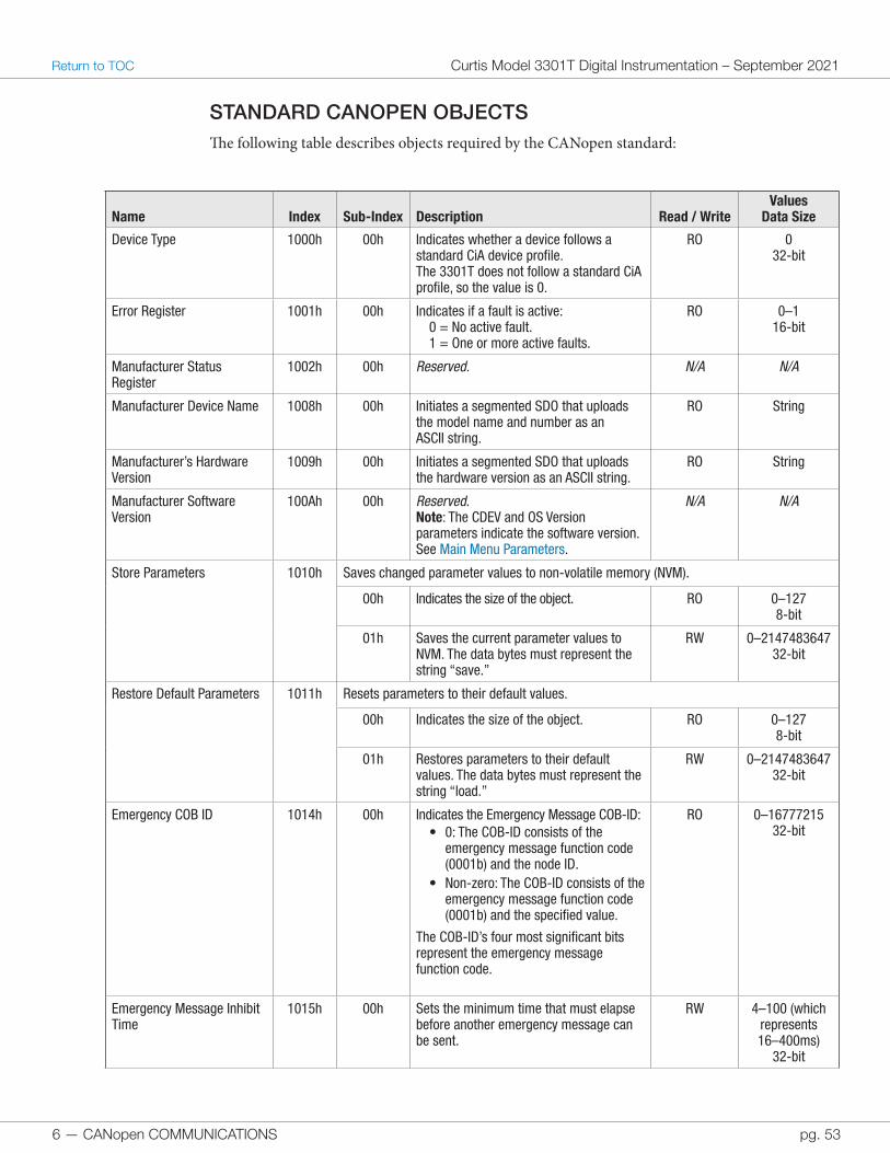
6 — CANopen COMMUNICATIONS pg. 53
Return to TOC Curtis Model 3301T Digital Instrumentation – September 2021
STANDARD CANOPEN OBJECTSThe following table describes objects required by the CANopen standard:
Name Index Sub-Index Description Read / WriteValues
Data Size
Device Type 1000h 00h Indicates whether a device follows a standard CiA device profile.The 3301T does not follow a standard CiA profile, so the value is 0.
RO 032-bit
Error Register 1001h 00h Indicates if a fault is active:0 = No active fault.1 = One or more active faults.
RO 0–116-bit
Manufacturer Status Register
1002h 00h Reserved. N/A N/A
Manufacturer Device Name 1008h 00h Initiates a segmented SDO that uploads the model name and number as an ASCII string.
RO String
Manufacturer’s Hardware Version
1009h 00h Initiates a segmented SDO that uploads the hardware version as an ASCII string.
RO String
Manufacturer Software Version
100Ah 00h Reserved.Note: The CDEV and OS Version parameters indicate the software version. See Main Menu Parameters.
N/A N/A
Store Parameters 1010h Saves changed parameter values to non-volatile memory (NVM).
00h Indicates the size of the object. RO 0–1278-bit
01h Saves the current parameter values to NVM. The data bytes must represent the string “save.”
RW 0–214748364732-bit
Restore Default Parameters 1011h Resets parameters to their default values.
00h Indicates the size of the object. RO 0–1278-bit
01h Restores parameters to their default values. The data bytes must represent the string “load.”
RW 0–214748364732-bit
Emergency COB ID 1014h 00h Indicates the Emergency Message COB-ID:• 0: The COB-ID consists of the
emergency message function code (0001b) and the node ID.
• Non-zero: The COB-ID consists of the emergency message function code (0001b) and the specified value.
The COB-ID’s four most significant bits represent the emergency message function code.
RO 0–1677721532-bit
Emergency Message Inhibit Time
1015h 00h Sets the minimum time that must elapse before another emergency message can be sent.
RW 4–100 (which represents 16–400ms)
32-bit
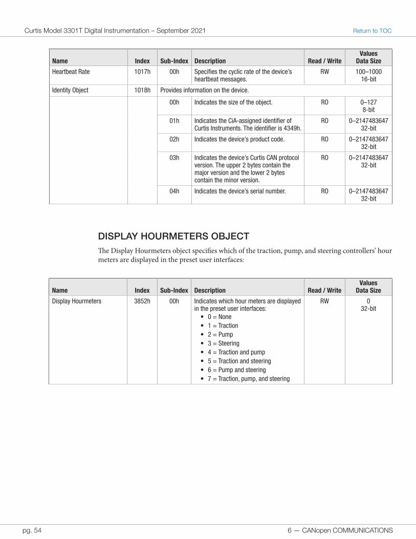
6 — CANopen COMMUNICATIONS
Curtis Model 3301T Digital Instrumentation – September 2021 Return to TOC
pg. 54
Name Index Sub-Index Description Read / WriteValues
Data Size
Heartbeat Rate 1017h 00h Specifies the cyclic rate of the device’s heartbeat messages.
RW 100–100016-bit
Identity Object 1018h Provides information on the device.
00h Indicates the size of the object. RO 0–1278-bit
01h Indicates the CiA-assigned identifier of Curtis Instruments. The identifier is 4349h.
RO 0–214748364732-bit
02h Indicates the device’s product code. RO 0–214748364732-bit
03h Indicates the device’s Curtis CAN protocol version. The upper 2 bytes contain the major version and the lower 2 bytes contain the minor version.
RO 0–214748364732-bit
04h Indicates the device’s serial number. RO 0–214748364732-bit
DISPLAY HOURMETERS OBJECTThe Display Hourmeters object specifies which of the traction, pump, and steering controllers’ hour meters are displayed in the preset user interfaces:
Name Index Sub-Index Description Read / WriteValues
Data Size
Display Hourmeters 3852h 00h Indicates which hour meters are displayed in the preset user interfaces:
• 0 = None• 1 = Traction• 2 = Pump• 3 = Steering• 4 = Traction and pump• 5 = Traction and steering• 6 = Pump and steering• 7 = Traction, pump, and steering
RW 032-bit
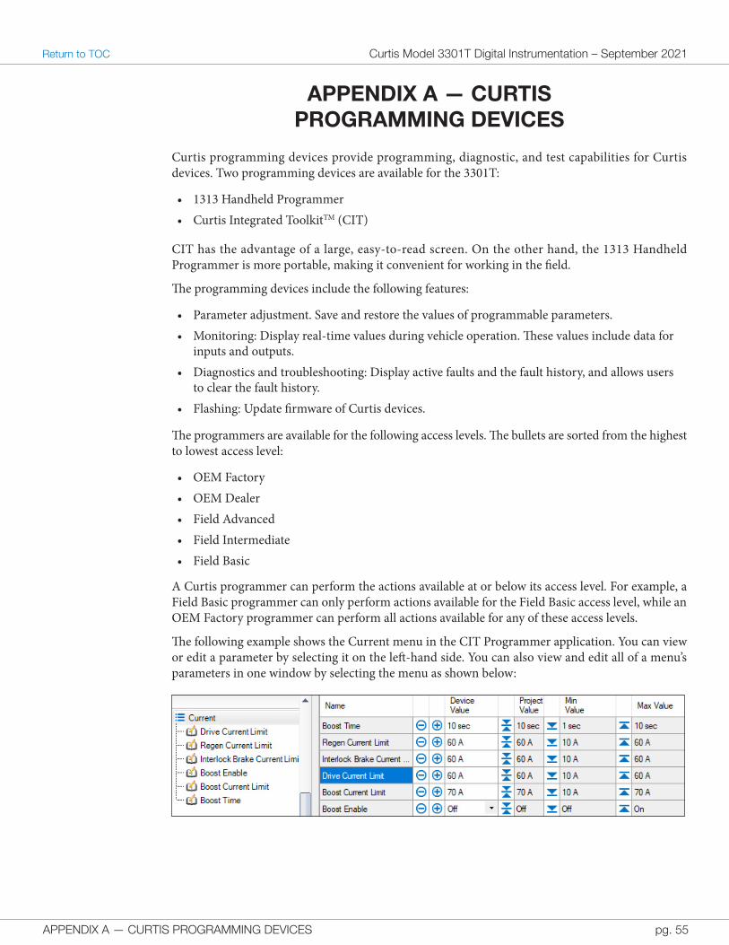
APPENDIX A — CURTIS PROGRAMMING DEVICES pg. 55
Return to TOC Curtis Model 3301T Digital Instrumentation – September 2021
APPENDIX A — CURTIS PROGRAMMING DEVICES
Curtis programming devices provide programming, diagnostic, and test capabilities for Curtis devices. Two programming devices are available for the 3301T:
• 1313 Handheld Programmer• Curtis Integrated ToolkitTM (CIT)
CIT has the advantage of a large, easy-to-read screen. On the other hand, the 1313 Handheld Programmer is more portable, making it convenient for working in the field.
The programming devices include the following features:
• Parameter adjustment. Save and restore the values of programmable parameters.• Monitoring: Display real-time values during vehicle operation. These values include data for
inputs and outputs.• Diagnostics and troubleshooting: Display active faults and the fault history, and allows users
to clear the fault history.• Flashing: Update firmware of Curtis devices.
The programmers are available for the following access levels. The bullets are sorted from the highest to lowest access level:
• OEM Factory• OEM Dealer• Field Advanced• Field Intermediate• Field Basic
A Curtis programmer can perform the actions available at or below its access level. For example, a Field Basic programmer can only perform actions available for the Field Basic access level, while an OEM Factory programmer can perform all actions available for any of these access levels.
The following example shows the Current menu in the CIT Programmer application. You can view or edit a parameter by selecting it on the left-hand side. You can also view and edit all of a menu’s parameters in one window by selecting the menu as shown below:
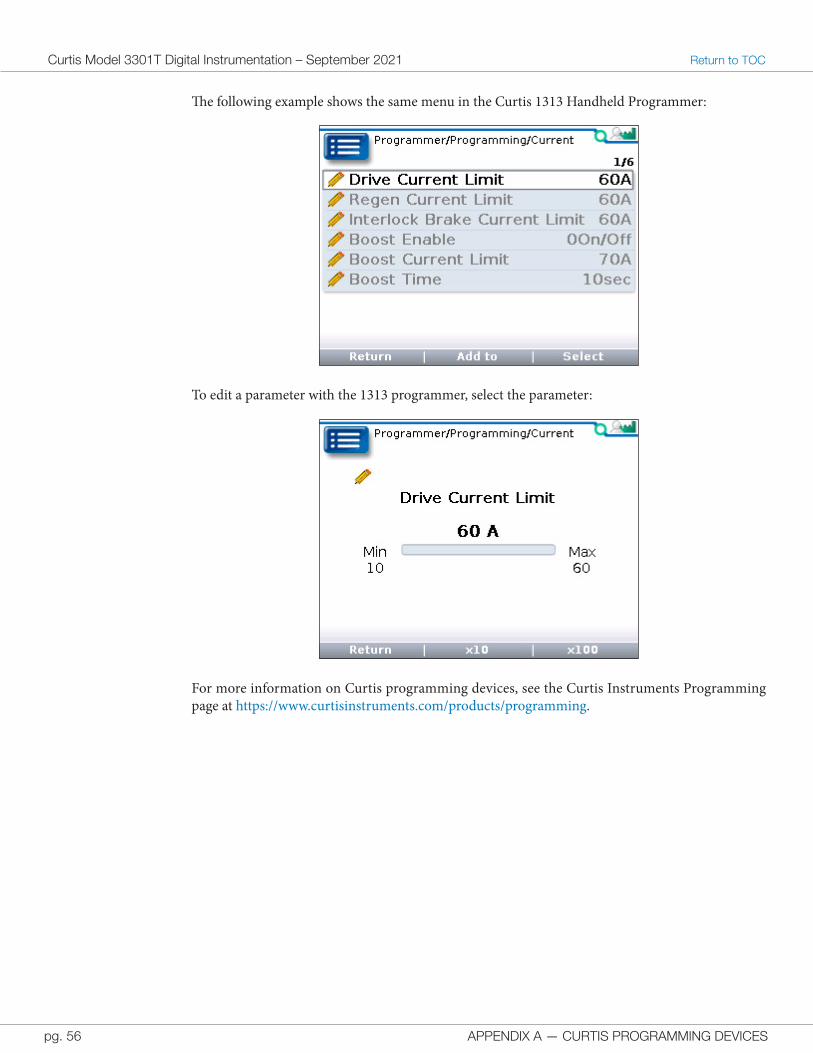
APPENDIX A — CURTIS PROGRAMMING DEVICES
Curtis Model 3301T Digital Instrumentation – September 2021 Return to TOC
pg. 56
The following example shows the same menu in the Curtis 1313 Handheld Programmer:
To edit a parameter with the 1313 programmer, select the parameter:
For more information on Curtis programming devices, see the Curtis Instruments Programming page at https://www.curtisinstruments.com/products/programming.
APPENDIX B — SPECIFICATIONS pg. 57
Return to TOC Curtis Model 3301T Digital Instrumentation – September 2021
APPENDIX B — SPECIFICATIONS
Nominal Voltage 12–96VDC
Minimum Voltage 9VDC
Maximum Voltage 120VDC
Minimum Startup Voltage 10VDC
Operating Current • Keyswitch on: 33–209mA• Keyswitch off: 24–110mA• LCD Heater On: 463–685mA
Dimensions 136 × 80 × 47.2 mm
Operating Temperature • With the LCD heater: –40°C to + 70°C• Without the LCD heater: –20°C to + 70°C
Storage Temperature –40°C to + 85°C
Humidity Designed to the following requirements:• Soak: EN 60068-2-78• Cyclic: EN 60068-2-30
Ingress Protection Designed to the requirements of EN 60529:• Face is sealed to IP65.• Rear is sealed to IP65 for electronic components and to IP40 for the connector.
Optional parts can increase the connector’s protection to IP54.
Salt Spray (Fog) Designed to the requirements of ASTM B 117-73 as per SAE J1810.
Shock Designed to the requirements of EN 60068-2-27.
Vibration Designed to the following requirements:• General: EN 60068-2-6• Random: EN 60068-2-64• Resonance: EN 60068-2-6
Safety Designed to the requirements of EN 61010-1: 2010, Part 1.
CE Designed to the following requirements:• EMC: EN 12895: 2015.• RoHS: RoHS directive 2015/863/EU (RoHS 3).
UL UL recognized component as per UL 583.
Model Encodement The model number encodement is 3301T-ZYYY where:• Z indicates whether the model includes the optional LCD heater:
– 5 = not included – 7 = included
• YYY is a sequential number code.
Note: Regulatory compliance of the complete system with the 3301T installed is the responsibility of the OEM.