Embed Size (px)
Citation preview

Manual Microscope PCE-VM 21
PCE Americas Inc.711 Commerce Way Suite 8 JupiterFL-33458USAFrom outside US: +1Tel: (561) 320-9162Fax: (561) [email protected]
www.pce-instruments.com/englishwww.pce-instruments.com
PCE Instruments UK Ltd.Units 12/13
Southpoint Business Park Ensign way
Hampshire / SouthamptonUnited Kingdom, SO31 4RF
From outside UK: +44Tel: (0) 2380 98703 0
Fax: (0) 2380 98703 9 [email protected]

User Guide
Video Microscope
PCE-VM 21/22/23
PCE Deutschland GmbH
Please read through the User Manual carefully before use.
1
Attentions 1. Do not disassemble the equipment without correct guide otherwise
faults or errors may happen. 2. High voltage inside, be careful, only a qualified person can open it. 3. The optical lens is pre-adjusted ready for instant use, disassembly is
not recommended. 4. The machine is a sophisticated precise optical instrument, and is
damageable, knock and impact is prohibited. 5. Careful operation is required to avoid damage. 6. Do not use the machine under humidity condition. 7. When the halogen lamp of PCE-VM 21 is working, it may be hot,
keep yourself/your skin and inflammable materials away from it to avoid burn or fire.
8. Do not use the machine under oily fuse or dirty conditions. 9. Please pull out the plug when the machine is not in use. 10. Please keep the machine in dry situation when it won’t be used
within a long time. 11. LED light is a original brand optional accessory, please do not use
other brands’, otherwise it might not light or damage the machine or the power supply.
12. Please note the parameters of the power supply, do not use other brands’ power supply.
To avoid damage during transportation, original package should be used to protect the sophisticated equipment, if lost; quality substitute package is required.
WARNING The display is vulnerable and may be damaged forever
should its interior parts are changed by any means, to avoid which please let a quali�ed person to disassemble and �x the machine when faults and dysfunctions happen。
The software can be downloaded here:https://www.pce-instruments.com/english/download-win_4.htm

CONTENT
Introduction ................................................................. 2
Framework of the microscope system......................... 2
Working principles of the video microscope system ..2
Functions and features................................................. 3
Parameters ................................................................... 3
Instruction of whole machine ...................................... 6
Operation and usage .................................................. 11
Dysfunctions diagnosis.............................................. 15
2
Introduction Consisting of varifocal microscope, CCD camera and LCD; PCE-VM
21/22/23 is a multi-functional microscope system set on the fixing
support. Besides, it can be connected to PC via the USB2.0 access,
which enables the system more powerful and applicable to wider usage
range.
Framework of the microscope system
Working principles of the video microscope system A clear picture of tiny object could be seen through the Microscope,
then, such picture would be grabbed and turned into video signal by the
CCD camera, and then, the video signal would turn into a digital picture
on the LCD display, meanwhile, the video signal will be transformed in
the signal transition box and then sent via the USD2.0 access to the
computer for display, picture-grapping, photographing, measuring,
saving and printing as well. Users can get the picture of ideal video
effect by turning the zooming ring of the lens section.

3
Functions and features 1. Ideal effect pictures for users’ comfortable watching.
2. Relieve the fatigue of and damage to the eyes results from long time
watching via the microscope.
3. Clear pictures of high resolution, wide visible range and zoom range.
4. All-in-one integration design, smart size, space saving.
5. Simple and easy to operate, stepless zooming range.
6. With “+” scale, for measurement and orientation reference.
7. LED lamp is easy to fix and operate, stepless lightness adjustable.
<LED lamp is an optional accessory>
8. Double halogen lamp, provide illumination from top & bottom,
stepless lightness adjustable. (for PCE-VM 21)
9. USB2.0 access enables the connection to computer for display,
picture-grapping, photographing, measuring, saving and printing as
well .
Application:
Electronics (Micro-electronics), mechanism processing, medicine &
biology, metallurgical industry, material analyzing, jewelry, education
and science research, etc.
Parameters 1. System magnification: 10X—75X
Remark: System magnification is the ratio of the size of the tested part
on the screen to that of the real tested object.
Relevant parameters: magnification of the object lens/CCD ocular, size
of CCD lens/display.
4
2. View range (mm) : 13.5 X 10 ~ 2.1 X 1.5
3. Optical object lens of the microscope system
Focus of the main optical lens: 0.7X-----4.5X (ratio: 1:6.5)
Focus of the CCD ocular: 0.5X
Focus of the entire optical lens: 0.35X----2.25X
Working distance: approx. 95 mm
3. CCD camera:
Size of lens: 1/3 inch.
Display chip: SONY
Horizontal visual resolution: 700TVL.
Video output: 1.0Vp-p 75Ω
Video mode: PAL
Working Voltage: DC 12V
2. LCD display:
Size: 8 inches.
Pixel: 600*800
Lattice proportion: 0.2×0.2 mm
Video input(output): 1.0Vp-p 75Ω
Work power: DC 12V (8W)
Video signal output mode: PAL
3. USB2.0 Display card:
Requirements for computer system:
CPU: Pentium III 800MHZ or above
Operating system: Windows 2000 or Windows XP.
Memory: 256MB above.
Hard disk capacity: 500MB above.
5
USB access: 2.0
Remark: The picture effect will be affected if the PC can not meet the
above settings.
4. Electrical index of the halogen lamp for PCE-VM 21G
Working voltage: 100—240V AC 50/60Hz
Power: upper lamp: 10W/12V bottom lamp: 10W/12V
5. LED lamp access (output) electrical index: (Notes: LED lamp is of
optional accessory)
Max. working voltage: DC 12V.
Voltage range: DC 7.5V-10.5V.
Max. working current :250MA.
(Notes: max. input current for the outer connected illumination should
not exceed 250mA.)
6. Working voltage for the whole machine:
Power supply: 100-240V AC 50/60Hz
Bottom power supply: 100-240V AC 50/60Hz
7. Physical parameters:
a> PCE-VM 23
Length on horizontal axis: 250mm
Height on vertical axis: 62+23mm
Weight for whole machine: approx. 4.5kgs
b> PCE-VM 21
Size of the base: 235(L) X 155(W) X 64(H)mm
Height on vertical axis: 250mm
Weight for whole machine: approx. 4.8kgs
c> PCE-VM 22
Size of the base: 235(L) X 155(W)mm
6
Height on vertical axis: 250mm
Weight for whole machine: approx. 3.55kgs
Notes: All the abovementioned parameters are subject to updates
without prior notice.
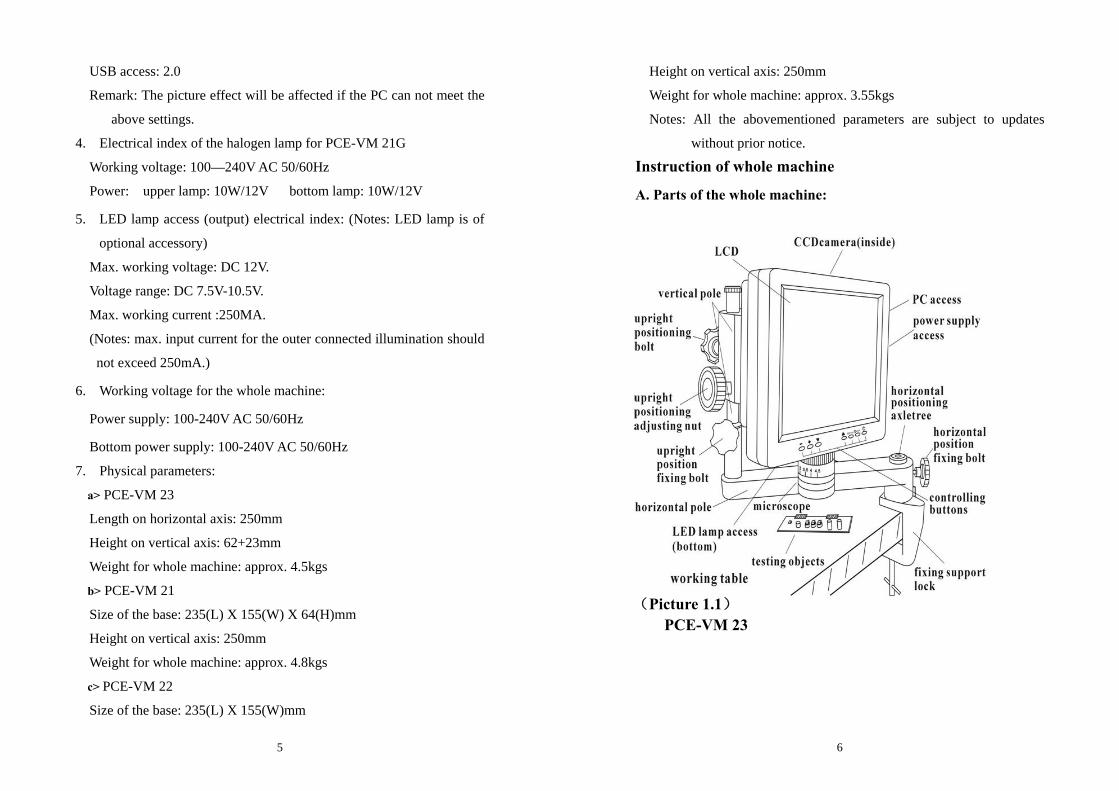
Instruction of whole machine
A. Parts of the whole machine:
(Picture 1.1) PCE-VM 23

7
(Picture 1.2)
PCE-VM 21
8
(Picture 1.3)
PCE-VM 22

9
B. Parts: B.1. Lens section & CCD camera
B.2. Access & LED lamp
(Picture 3)
(Picture 2)
10
B.3. Moving platform carrier (optional accessory)
B.4. Function Buttons:
①: Power on/off button of the LCD display screen
②: Power on/off of up halogen lamp/confirming OSD parameters
adjustment
③: OSD menu; enter into OSD menu, and its items and options.
④⑤: Choosing the menu and its item and options.
⑥⑦: Adjusting lightness of the up halogen lamp; choosing items and
options in the menu.
⑧: Power on/off indicator
(Picture 5)
(Picture 4)

11
Operation and usage Installation: firstly, fix the fixing support of PCE-VM 23 lock in
suitable place onto the working table, secondly, set the
installed main body into the horizontal positioning axletree,
thirdly, adjust the horizontal pole so that the lens aims at
the testing objects, lastly, adjust the LCD display screen in
a suitable visual angle; while PCE-VM 21 G & PCE-VM
22 G can be put on working table directly for instant use.
Pull the power adaptor plug into the socket.
Turn on/off: connect the machine to the power source, the power
indicator(button ⑧) will turn on, press button to turn on
the display, meanwhile, the power indicator will turn off;
when working, press the button to turn off the display,
meanwhile, the power indicator will turn on..
Attention: Please pull out the plug cut the power supply when the
equipment is not in use, otherwise the power adaptor, CCD
and display will keep on working.
Adjusting:
1) Adjust the imaging: place the testing objects under the lens, loosen
the vertical positioning bolt to adjust the height of microscope and
make the distance between the object with the surface of lens is
100mm, and then adjust the focus adjusting cirque to make the
image clear. Finally, turn slightly the upright positioning adjusting
nut so that the lens will go up and down to zoom in and out, till get
the image of the best effect.
2) Adjust the zooming times: turn the focus adjusting cirque to get
12
suitable zooming times.
3) Adjust the lightness: lightness plays an important role in imaging,
weak lightness makes the image dim and not clear while strong
lightness changes the original colors of the object’s image. The more
spectrums, the more vivid the imaging will be. Moreover, refraction
of the light also affects the imaging quality. So the illumination and
lightness have to be carefully chosen and adjusted.
Installation and usage of the LED lamp:
a. lock the LED lamp to the lens tightly.
b. insert the plug of LED into correspondent access/socket.
c. press button “ /OK”, the correspondent mark appears in the right
up corner of the screen , and the lamp is on. (direct pressing “+”or
“-“ will also turn on the LED lamp)
d. press “+” “ -“ to adjust the lightness.
e. once the lightness becomes ideal, press button “ /OK” to
confirm and quit.
f. When the LED lamp is on, press button “ /OK” , the
correspondent mark and the lamp will be off. <Notes: LED lamp is
an optional accessory>
4) Adjust the parameters of the image & system setting:
OSD can be adjusted via buttons. OSD includes “image” and
“settings”.” While “image” includes “brightness”, “contrast”,
“saturation” and “hue”, users can adjust these parameters at their
wills. “Settings” includes “language”, “scale”, and “default”.
“language”: 9 languages available.
“scale”: 10mm for a big graduation of scale while 5mm for a small one.
(Notes: the scale is just for reference only.)
“default”: recover the factory settings.

13
Image adjusting:
a. press “MENU” to enter into the sub-menu “image”.
b. press “MENU” again and the option “brightness” is selected and
ready for adjustment
c. to adjust the brightness, press “+” or “-“, to activate other options,
press “▽”or“△”.
d. once the options is selected, press “+” or “-“ for adjustment.
e. when adjustments finish, press button “ /OK” to confirm and
quit.
System “settings”:
a. press “MENU” to enter into the sub-menu “image”.
b. press “▽”or“△”to enter into sub-menu “settings”.
14
c. press ”menu”, then option “language” is selected and ready for
adjustment.
d. to change the language, press “+” or “-“.
e. to select “scale”, press the button“▽”, then the options “on” “off” are
selected, press “+” or “-“ to activate or close “scale”.
f. to recover the factory settings, press “▽”or“△”to select the option
“default”, then press “+” or “-“ to recover or quit the factory
settings.
g. when adjustments finish, press button “ /OK” to confirm and quit.
AV OUT (av signal outlet): enable the machine to be connected with
exterior display for better watching.
Installation of USB2.0 display card
The system of PCE-VM 21\22\23 is equipped with USB/PC access
(see picture 3), which enables it to be connected with computer and thus

15
extends its functions. For the first time using, the drive software for
display card and operation interface software for computer should be
activated/set up:
1. Check the computer’s parameters and make sure they meet the
requirements stated in the point “4.USB2.0 Display card in the
“Requirements for computer system”.
2. Connect the machine to computer via the USB2.0 access, and then
activate the system.
3. Put the drive disk of USB2.0 display card into the computer’s disk
driver; finish the installation of the driving procedures according to
the guide of Instruction of USB2.0 and computer indications.
4. After the driving procedures finished, click to activate the operation
software, finish the installation of the USB2.0 display card according
to the guide of Instruction of USB2.0 and computer indications.
5. After the above steps, check and make sure the installation is
successful, and then computer operation can be stared.
Note: For installation steps, please refer to “Installation of USB2.0
Driving Progress for the Video Microscope”.
Dysfunctions diagnosis
1. Vague image:
Generally results from the improperly adjusted working distance,
please re-check and make sure the working distance is approx 95mm
as required.
2. Image is dim, unclear, colorless, red, and with “snow stains”:
Generally results from weak lightness/brightness, please adjust
lightness/brightness properly strong.
3. Image is too white:
16
Generally results from strong lightness/brightness, please adjust
lightness/brightness to a properly extent.
4. Image with white spot:
Generally results from refraction of the light or strong
lightness/brightness, please adjust the light incidence and the
lightness/brightness to a properly extent. Normally, scattering light is
a better mean of illumination.
5. No image appears on the display screen:
This may result from many factors, among which the most common
two are display screen dysfunction and signal dysfunction. When this
happens, first, check whether the power supply system is properly
working or not; open the top cover of the machine, if the indicator of
CCD camera is on, it means the power supply system is all right, then
the below procedures should be followed:
(1) Display screen dysfunction: Normally, if the display screen is OK,
press button ①, the caught image or the two-second “no signal”
-14-
indication should be on the screen, otherwise display screen
dysfunctions can be deemed affirmative. This symptom can also
be judged from the exterior display connected via the AV OUT
outlet.
(2) No signal dysfunction: When no signals are sent to the display, the
backlight of the display screen will be off even it is power on, so
no image appears on the screen. When this happens, please check
the pass through which the signals are transmitted. Normally, the
ocular microscope is deeded to be ok without outside force, and if
the video signal transmitting wire is ok, then CCD camera will be
17
considered to arise.
Attention:
① If any dysfunction happens to CCD camera or display screen,
please contact the supplier for repair.
② Please take care of the power supply voltage, wire polarity and the
video format, if users want to change the CCD camera by
themselves.
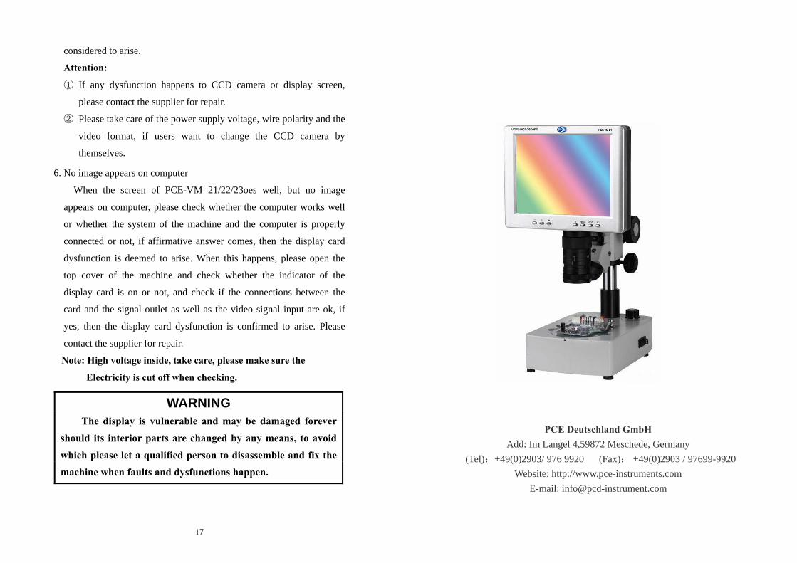
6. No image appears on computer
When the screen of PCE-VM 21/22/23oes well, but no image
appears on computer, please check whether the computer works well
or whether the system of the machine and the computer is properly
connected or not, if affirmative answer comes, then the display card
dysfunction is deemed to arise. When this happens, please open the
top cover of the machine and check whether the indicator of the
display card is on or not, and check if the connections between the
card and the signal outlet as well as the video signal input are ok, if
yes, then the display card dysfunction is confirmed to arise. Please
contact the supplier for repair.
Note: High voltage inside, take care, please make sure the
Electricity is cut off when checking.
WARNING The display is vulnerable and may be damaged forever
should its interior parts are changed by any means, to avoid which please let a qualified person to disassemble and fix the machine when faults and dysfunctions happen.
PCE Deutschland GmbH Add: Im Langel 4,59872 Meschede, Germany
(Tel):+49(0)2903/ 976 9920 (Fax): +49(0)2903 / 97699-9920 Website: http://www.pce-instruments.com
E-mail: [email protected]