Embed Size (px)
Citation preview
INSTALLATION, SERVICE AND MAINTENANCE
INSTRUCTIONS
PROGRESSIVE CAVITY PUMP
KIBER KSF / KSFT
INOXPA, S.A. c/Telers, 54 Aptdo. 174
E-17820 Banyoles Girona (Spain)
Tel. : (34) 972 - 57 52 00 Fax. : (34) 972 - 57 55 02 Email: [email protected]
www.inoxpa.com
Original Manual 01.611.30.06EN
(A) 2014/03
EC Declaration of Conformity
The manufacturer: INOXPA, S.A.
c/ Telers, 57 17820 Banyoles (Girona), Spain
herewith declares that the machine:
KIBER KSF – KSFT Progressive Cavity pump
with the serial number: ________________ conforms to the relevant provisions of the following directives:
Machinery Directive 2006/42/EC (RD 1644/2008) Low voltage Directive 2006/95/EC Electromagnetic Compatibility Directive 2004/108/EC
Applicable harmonised Standards:
UNE-EN ISO 12100:2012 UNE-EN 809:1999+A1:2010 Identification of the person empowered to draw up the Declaration on behalf of the manufacturer, and qualified to compile the technical file established by the Community:
Banyoles, 8 January 2014
David Reyero Brunet Technical Office Manager
2014/03 1.Safety 3
1. Safety
1.1. INSTRUCTIONS MANUAL This manual contains information about the reception, installation, operation, assembly, disassembly and maintenance of the KIBER KSF / KSFT pumps. The information provided in this Instructions Manual is based on updated facts. INOXPA reserves the right to modify this Instructions Manual without prior notice.
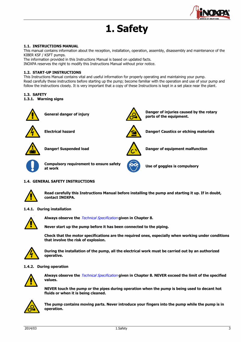
1.2. START-UP INSTRUCTIONS This Instructions Manual contains vital and useful information for properly operating and maintaining your pump. Read carefully these instructions before starting up the pump; become familiar with the operation and use of your pump and follow the instructions closely. It is very important that a copy of these Instructions is kept in a set place near the plant. 1.3. SAFETY 1.3.1. Warning signs
General danger of injury
Danger of injuries caused by the rotary parts of the equipment.
Electrical hazard
Danger! Caustics or etching materials
Danger! Suspended load
Danger of equipment malfunction
Compulsory requirement to ensure safety at work
Use of goggles is compulsory
1.4. GENERAL SAFETY INSTRUCTIONS
Read carefully this Instructions Manual before installing the pump and starting it up. If in doubt, contact INOXPA.
1.4.1. During installation
Always observe the Technical Specification given in Chapter 8. Never start up the pump before it has been connected to the piping. Check that the motor specifications are the required ones, especially when working under conditions that involve the risk of explosion.
During the installation of the pump, all the electrical work must be carried out by an authorized
operative.
1.4.2. During operation
Always observe the Technical Specification given in Chapter 8. NEVER exceed the limit of the specified values. NEVER touch the pump or the pipes during operation when the pump is being used to decant hot fluids or when it is being cleaned.
The pump contains moving parts. Never introduce your fingers into the pump while the pump is in operation.
4 1.Safety 2014/03
NEVER operate the pump with the inlet and discharge valves closed.
NEVER spray the electrical motor directly with water. The standard protection of the motor is IP- 55: Protection against dust and spraying water.
1.4.3. During maintenance
Always observe the Technical Specification given in Chapter 8. NEVER disassemble the pump before the pipes have been emptied. Remember that some of the fluid will always remain in the pumpcasing (when no drainage is provided). Note that the pumped fluid may be dangerous or very hot. Please refer to the regulations applicable in the respective country. Do not leave detached parts on the floor.
ALWAYS disconnect the pump from the power before beginning the maintenance. Remove the fuses and disconnect the cables from the motor terminals.
All the electrical work must be carried out by an authorized operative. 1.4.4. Compliance with the instructions Any failure to comply with the instructions might entail risks to the operators, the environment and the equipment, and result in the loss of the right to claim for damages. Such non-compliance might entail the following risks:
Failure of important functions of the equipment / plant. Failure of specific maintenance and repair procedures. Threat of electrical, mechanical and chemical risks. Environmental risks caused by the release of substances.
1.4.5. Warranty
Any warranty provided shall immediately and ipso jure become void, and INOXPA shall be indemnified against any product
liability claim from third parties, if: the service and maintenance work was not carried out in accordance to the service instructions, or the repair work
has not been carried out by our personnel or it has been carried without our written authorization; our materials have been changed without prior written authorization;
the parts or lubricants used are not original INOXPA parts and products; the materials were used improperly or carelessly, or not in accordance to these instructions and their intended use; pump parts were damaged by strong pressure for lack of a safety valve.
The General Delivery Terms already furnished to you also apply.
No change can be made to the equipment without prior discussion with the manufacturer. For your safety, please use original spare parts and accessories. The use of other parts will release the manufacturer from any liability. The service terms can only be changed with prior written authorisation from INOXPA.
When in doubt, or if you need more detailed information on specific matters (adjustment, assembly, disassembly, etc.), please do not hesitate to contact us.
2014/03 2.Index 5
2. Index
1. Safety 3
1.1. Instructions manual ....................................................................................................... 3
1.2. Start-up instructions ...................................................................................................... 3
1.3. Safety .......................................................................................................................... 3
1.4. General safety instructions ............................................................................................. 3
2. Index 5
3. General information 6
3.1. Description ................................................................................................................... 6
3.2. Range of applications .................................................................................................... 6
4. Installation 7
4.1. Reception of the pump .................................................................................................. 7
4.2. Handling and storage .................................................................................................... 7
4.3. Location ....................................................................................................................... 8
4.4. Pipes ............................................................................................................................ 8
4.5. Pressurisation tank ........................................................................................................ 8
4.6. Electric wiring ............................................................................................................... 9
5. Start-up 10
5.1. Start-up ..................................................................................................................... 10
5.2. By-pass pressure ......................................................................................................... 10
6. Operating problems 11
7. Maintenance 12
7.1. General ...................................................................................................................... 12
7.2. Storage ...................................................................................................................... 12
7.3. Cleaning ..................................................................................................................... 12
7.4. Disassembly / Assembly of the pump ............................................................................ 13
8. Technical specifications 17
8.1. Technical specifications ................................................................................................ 17
8.2. Weights ...................................................................................................................... 18
8.3. Pump dimensions with by-pass pressure ....................................................................... 18
8.4. KSF pump dimensions ................................................................................................. 19
8.5. KSFT pump dimensions ................................................................................................ 20
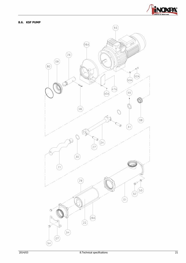
8.6. KSF pump ................................................................................................................... 21
8.7. Parts list KSF .............................................................................................................. 22
8.8. KSFT pump ................................................................................................................. 23
8.9. Parts list KSFT............................................................................................................. 24
8.10. Heavy duty transmission ............................................................................................ 25
8.11. Cooled mechanical seal .............................................................................................. 26
6 3.General information 2014/03
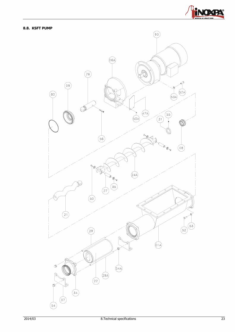
3. General information 3.1. DESCRIPTION With a compact and robust design, INOXPA’s KSF/KSFT progressive cavity pumps form part of our range of positive-displacement pumps with helical rotor, intended for viscous fluids. The hydraulic parts that form the pump are the rotor and the stator. The rotor is a round-section worm. The stator has two ribs and its pitch doubles that of the rotor, thus allowing empty cavities between the stator and the rotor. These cavities are used to transport the fluid. When the rotor turns within the stator, the cavities move longitudinally from the suction area to the discharge nozzle. These kinds of pumps are suitable for pressures from 6 bar (single-stage stator) to 12 bar (double-stage stator). KSF pumps are designed with a fully health-compliant and easy-to-clean transmission. For KSFT, bolts are fixed through some countersink. The standard connections are DN 11851. The discharge nozzle is eccentric. Moreover, there is a more robust design of transmission for a longer service life under heavy duty working conditions. Also it is possible to choose other types of connections for the pump, like the CLAMP, SMS, RJT, flanges DIN-2633 PN-16, etc.
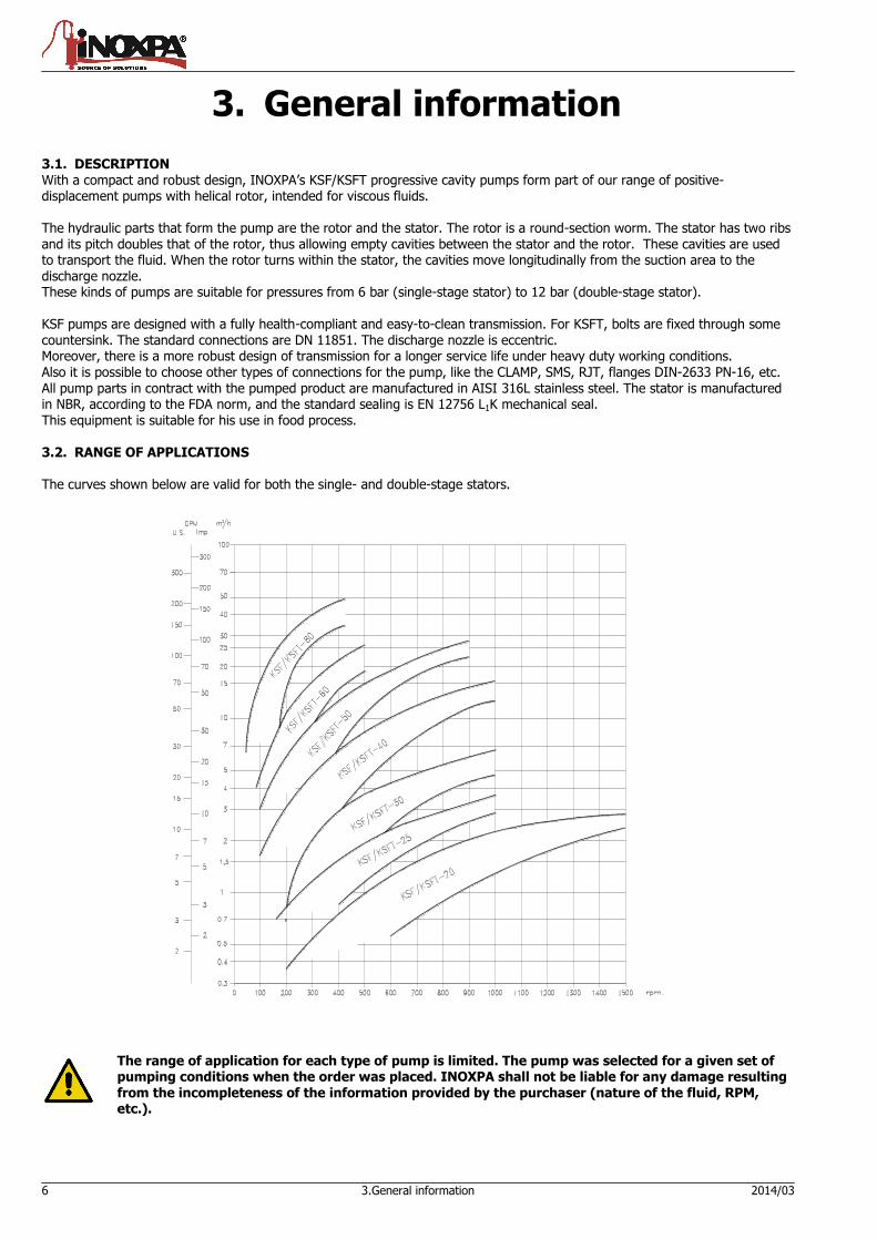
All pump parts in contract with the pumped product are manufactured in AISI 316L stainless steel. The stator is manufactured in NBR, according to the FDA norm, and the standard sealing is EN 12756 L1K mechanical seal. This equipment is suitable for his use in food process. 3.2. RANGE OF APPLICATIONS The curves shown below are valid for both the single- and double-stage stators.
The range of application for each type of pump is limited. The pump was selected for a given set of pumping conditions when the order was placed. INOXPA shall not be liable for any damage resulting from the incompleteness of the information provided by the purchaser (nature of the fluid, RPM, etc.).
2014/03 4.Installation 7
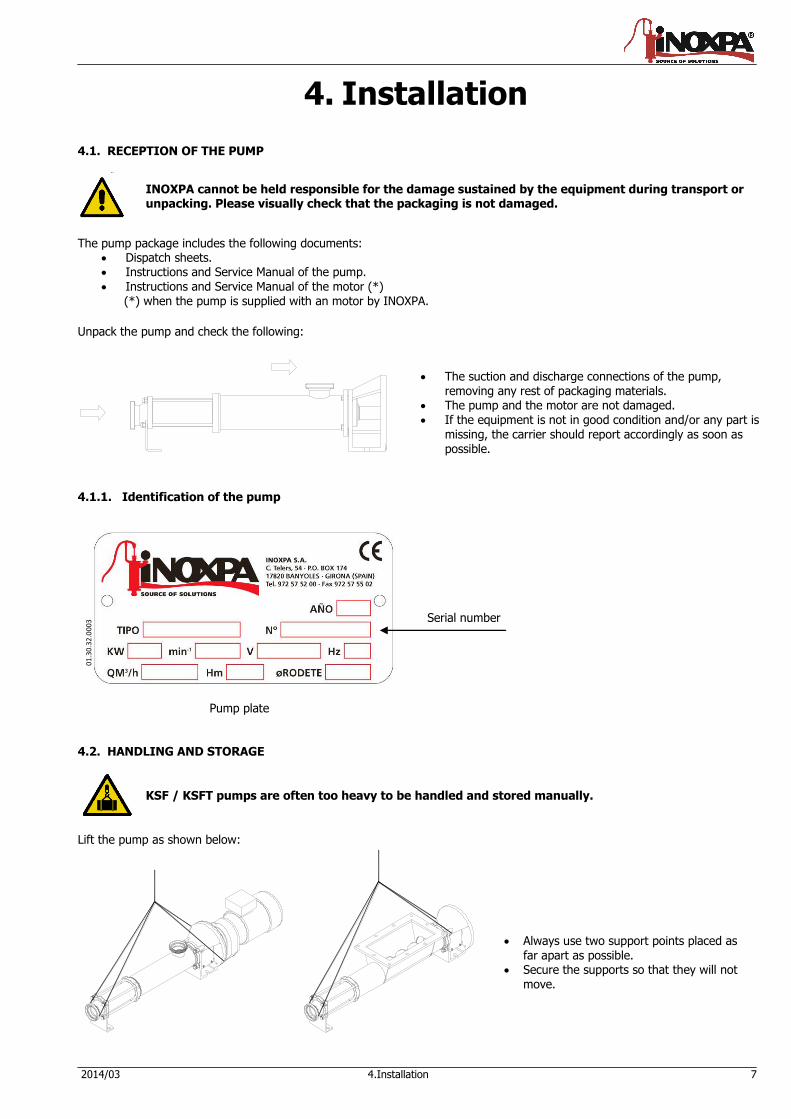
Serial number
4. Installation
4.1. RECEPTION OF THE PUMP
INOXPA cannot be held responsible for the damage sustained by the equipment during transport or unpacking. Please visually check that the packaging is not damaged.
The pump package includes the following documents: Dispatch sheets. Instructions and Service Manual of the pump. Instructions and Service Manual of the motor (*) (*) when the pump is supplied with an motor by INOXPA.
Unpack the pump and check the following:
The suction and discharge connections of the pump,
removing any rest of packaging materials. The pump and the motor are not damaged. If the equipment is not in good condition and/or any part is
missing, the carrier should report accordingly as soon as possible.
4.1.1. Identification of the pump
01
.30
.32
.00
03
Pump plate 4.2. HANDLING AND STORAGE
KSF / KSFT pumps are often too heavy to be handled and stored manually.
Lift the pump as shown below:
Always use two support points placed as
far apart as possible. Secure the supports so that they will not
move.
8 4.Installation 2014/03
4.3. LOCATION
Place the pump as close as possible to the suction tank, and if possible below the fluid level. Place the pump so as to allow around it space enough to access the pump and the motor. (See Chapter 8 Technical Specification for dimensions and weight). Mount the pump on a flat, level surface. The foundation must be rigid, horizontal, level and vibration-proof.
Install the pump so as to allow proper ventilation. If the pump is installed outdoors, it should be covered by a roof. Its location should allow easy access for inspection or maintenance operations.
4.4. PIPES
As general rule, fit the suction and discharge pipes in straight sections, with the least possible number of bends and accessories in order to reduce as much as possible any loss of load caused by friction.
Make sure that the nozzles of the pump are properly aligned to the pipe and their diameter is similar to that of the pump connections.
Place the pump as close as possible to the suction tank, if possible below the fluid level, or even below the tank, so
that the manometric head of the static suction is highest. Place pipe supports as close as possible to the suction and discharge nozzles of the pump.
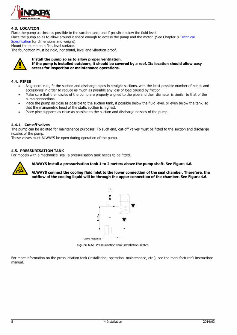
4.4.1. Cut-off valves The pump can be isolated for maintenance purposes. To such end, cut-off valves must be fitted to the suction and discharge nozzles of the pump. These valves must ALWAYS be open during operation of the pump. 4.5. PRESSURISATION TANK For models with a mechanical seal, a pressurisation tank needs to be fitted.
1...2
m
Cierre mecánico
Figure 4.6: Pressurisation tank installation sketch
For more information on the pressurisation tank (installation, operation, maintenance, etc.), see the manufacturer’s instructions manual.
ALWAYS install a pressurisation tank 1 to 2 meters above the pump shaft. See Figure 4.6. ALWAYS connect the cooling fluid inlet to the lower connection of the seal chamber. Therefore, the outflow of the cooling liquid will be through the upper connection of the chamber. See Figure 4.6.
2014/03 4.Installation 9
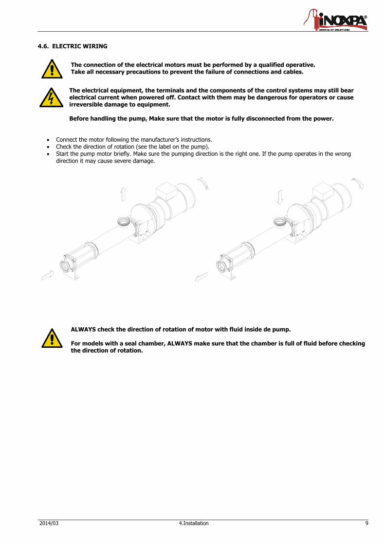
4.6. ELECTRIC WIRING
The connection of the electrical motors must be performed by a qualified operative. Take all necessary precautions to prevent the failure of connections and cables.
The electrical equipment, the terminals and the components of the control systems may still bear electrical current when powered off. Contact with them may be dangerous for operators or cause irreversible damage to equipment. Before handling the pump, Make sure that the motor is fully disconnected from the power.
Connect the motor following the manufacturer’s instructions. Check the direction of rotation (see the label on the pump). Start the pump motor briefly. Make sure the pumping direction is the right one. If the pump operates in the wrong
direction it may cause severe damage.
ALWAYS check the direction of rotation of motor with fluid inside de pump. For models with a seal chamber, ALWAYS make sure that the chamber is full of fluid before checking the direction of rotation.
10 5.Start-up 2014/03
5. Start-up
Before starting the pump, carefully read the instructions given in Chapter 4. Installation.
5.1. START-UP
Read Chapter 8 Technical Specification carefully. INOXPA cannot be held responsible for the improper use of the equipment.
NEVER touch the pump or the pipes when hot fluid is being pumped.
5.1.1. Checks before starting up the pump
Fully open the cut-off valves on the suction and discharge pipes. If the fluid does not flow into the pump, fill the pump with fluid.
The pump must NEVER rotate without fluid inside it.
Check that the power supply matches the rating indicated on the motor plate. Check that the direction of rotation of motor is the right one. If the pump has a double or a cooled mechanical seal, mount the auxiliary connection corresponding to the values
indicated in Chapter 8, Technical Specification.
5.1.2. Checks when starting up the pump
Check whether the pump makes strange sounds.
Check whether the absolute inlet pressure is enough to avoid cavitation in the pump. See the curve to determine the minimum pressure required above steam pressure (NPSHr).
Control discharge pressure. Check that there are no leaks through the sealed areas.
A cut-off valve on the suction pipe must no be used to regulate flow. Cut-off valves must be fully open during operation.
Control motor consumption to avoid power overload.
Reduce flow and motor power consumption by reducing motor speed. 5.2. BY-PASS PRESSURE
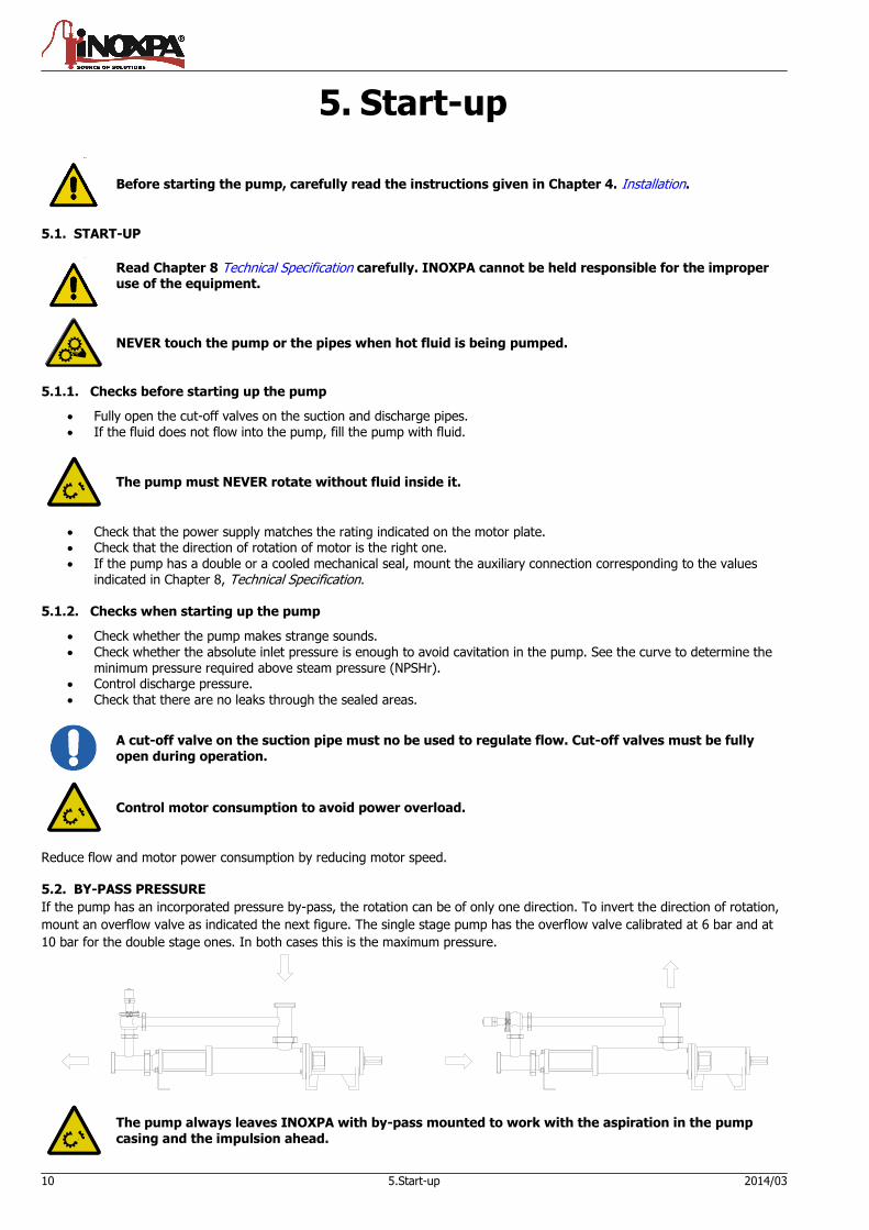
If the pump has an incorporated pressure by-pass, the rotation can be of only one direction. To invert the direction of rotation,
mount an overflow valve as indicated the next figure. The single stage pump has the overflow valve calibrated at 6 bar and at
10 bar for the double stage ones. In both cases this is the maximum pressure.
The pump always leaves INOXPA with by-pass mounted to work with the aspiration in the pump casing and the impulsion ahead.
2014/03 6.Operating problems 11
6. Operating problems
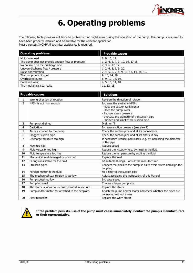
The following table provides solutions to problems that might arise during the operation of the pump. The pump is assumed to
have been properly installed and be suitable for the relevant application. Please contact INOXPA if technical assistance is required.
Operating problems Probable causes
Motor overload 8, 9, 13, 19.
The pump does not provide enough flow or pressure 1, 2, 4, 5, 7, 9, 10, 16, 17,18.
No pressure on the discharge side 2, 3, 6, 17, 17.
Uneven discharge flow / pressure 1, 2, 4, 5, 6, 9, 20.
Noise and vibration 2, 4, 5, 6, 7, 8, 9, 10, 13, 14, 18, 19.
The pump gets clogged 9, 10, 14, 19.
Overheated pump 8, 9, 10, 14, 19.
Excessive wear 4, 5, 10, 14, 18.
The mechanical seal leaks 11, 12, 15.
Probable causes Solutions
1 Wrong direction of rotation Reverse the direction of rotation
2 NPSH is not high enough Increase the available NPSH: - Place the suction tank higher - Place the pump lower - Reduce steam pressure - Increase the diameter of the suction pipe - Shorten and simplify the suction pipe
3 Pump not drained Drain or fill
4 Cavitation Increase suction pressure (see also 2)
5 Air is suctioned by the pump. Check the suction pipe and all its connections
6 Clogged suction pipe Check the suction pipe and all its filters, if any
7 Discharge pressure too high If necessary, reduce load losses, e.g. by increasing the diameter of the pipe
8 Flow too high Reduce speed
9 Fluid viscosity too high Reduce the viscosity, e.g. by heating the fluid
10 Fluid temperature too high Reduce the temperature by cooling the fluid
11 Mechanical seal damaged or worn out Replace the seal
12 O-rings unsuitable for the fluid Fit suitable O-rings. Consult the manufacturer.
13 Stressed pipes Connect the pipes to the pump so as to avoid stress and align the coupling
14 Foreign matter in the fluid Fit a filter to the suction pipe
15 The mechanical seal tension is too low Adjust according the instructions of this Manual
16 Pump speed too low Increase speed
17 Pump too small Choose a larger pump size
18 The stator is worn out or has operated in vacuum Replace the stator
19 Pump and/or motor not attached to the bedplate. Attach the pump and/or motor and check whether the pipes are connected without stress
20 Flow reduction Replace the worn stator
If the problem persists, use of the pump must cease immediately. Contact the pump’s manufacturers or their representative.
12 7.Maintenance 2014/03
7. Maintenance
7.1. GENERAL Like any other machine, this pump requires maintenance. The instructions included in this manual cover the identification and replacement of spare parts. These instructions are intended for the maintenance personnel and those responsible for the supply of spare parts.
Please carefully read Chapter 8 Technical specification. All replaced materials must be disposed of /recycled in accordance to the applicable local regulations.
ALWAYS disconnect the pump from the power before performing the maintenance.
7.1.1. Check the mechanical seal Regularly check that there are no leaks in the shaft area. If there are leaks through the mechanical seal, replace it following the instructions given under the Disassembly and Assembly section. 7.2. STORAGE The pump must be completely emptied of fluid before storage. If possible, avoid exposing the components of the pump to excessively humid environments. 7.3. CLEANING
The use of aggressive cleaning products, such as caustic soda and nitric acid, can cause skin burns. Use rubber gloves during cleaning procedures.
Always use protective goggles.
7.3.1. Automatic CIP (cleaning-in-place) If the pump is installed in a system with a CIP process, it is not necessary to disassemble the pump. If the automatic cleaning process is not provided, proceed to disassemble the pump as indicated in the Disassembly and Assembly section.
Cleaning solutions for CIP processes
Use only clear water (without chlorides) for mixing with the cleaning agents:
a) Alkaline solution: 1% in weight of caustic soda (NaOH) at 70ºC (150ºF)
1 Kg NaOH + 100 l. water = cleaning solution
or
2,2 l. NaOH at 33% + 100 l. water = cleaning solution
b) Acid solution: 0,5% in weight of nitric acid (HNO3) at 70ºC (150ºF)
0.7 liters HNO3 at 53% + 100 l. water = cleaning solution
Control the concentration of the cleaning solutions to avoid deterioration of the pump seals.
To remove the remaining cleaning products, ALWAYS perform a final rinse with clean water on completion of the cleaning process.
2014/03 7.Maintenance 13
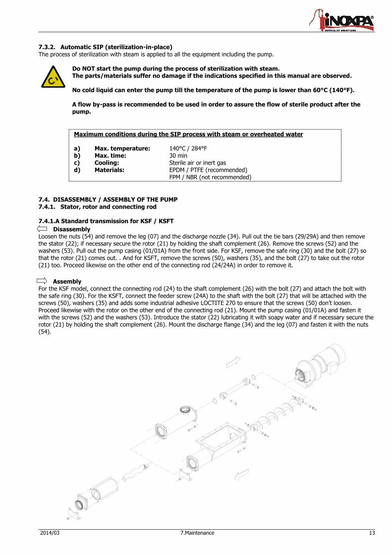
7.3.2. Automatic SIP (sterilization-in-place)
The process of sterilization with steam is applied to all the equipment including the pump.
Do NOT start the pump during the process of sterilization with steam. The parts/materials suffer no damage if the indications specified in this manual are observed. No cold liquid can enter the pump till the temperature of the pump is lower than 60°C (140°F). A flow by-pass is recommended to be used in order to assure the flow of sterile product after the pump.
Maximum conditions during the SIP process with steam or overheated water a) Max. temperature: 140°C / 284°F b) Max. time: 30 min c) Cooling: Sterile air or inert gas d) Materials: EPDM / PTFE (recommended)
FPM / NBR (not recommended)
7.4. DISASSEMBLY / ASSEMBLY OF THE PUMP 7.4.1. Stator, rotor and connecting rod 7.4.1.A Standard transmission for KSF / KSFT
Disassembly Loosen the nuts (54) and remove the leg (07) and the discharge nozzle (34). Pull out the tie bars (29/29A) and then remove the stator (22); if necessary secure the rotor (21) by holding the shaft complement (26). Remove the screws (52) and the washers (53). Pull out the pump casing (01/01A) from the front side. For KSF, remove the safe ring (30) and the bolt (27) so that the rotor (21) comes out. . And for KSFT, remove the screws (50), washers (35), and the bolt (27) to take out the rotor (21) too. Proceed likewise on the other end of the connecting rod (24/24A) in order to remove it.
Assembly For the KSF model, connect the connecting rod (24) to the shaft complement (26) with the bolt (27) and attach the bolt with
the safe ring (30). For the KSFT, connect the feeder screw (24A) to the shaft with the bolt (27) that will be attached with the screws (50), washers (35) and adds some industrial adhesive LOCTITE 270 to ensure that the screws (50) don’t loosen. Proceed likewise with the rotor on the other end of the connecting rod (21). Mount the pump casing (01/01A) and fasten it with the screws (52) and the washers (53). Introduce the stator (22) lubricating it with soapy water and if necessary secure the rotor (21) by holding the shaft complement (26). Mount the discharge flange (34) and the leg (07) and fasten it with the nuts (54).
14 7.Maintenance 2014/03
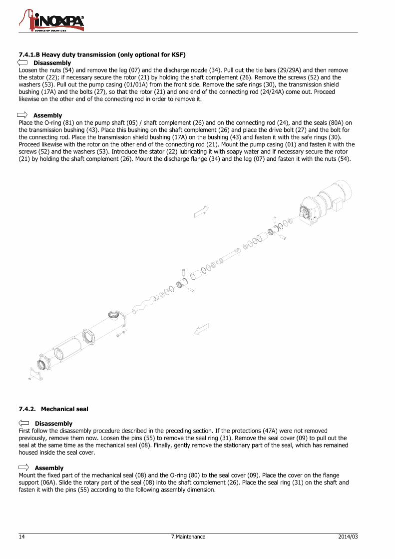
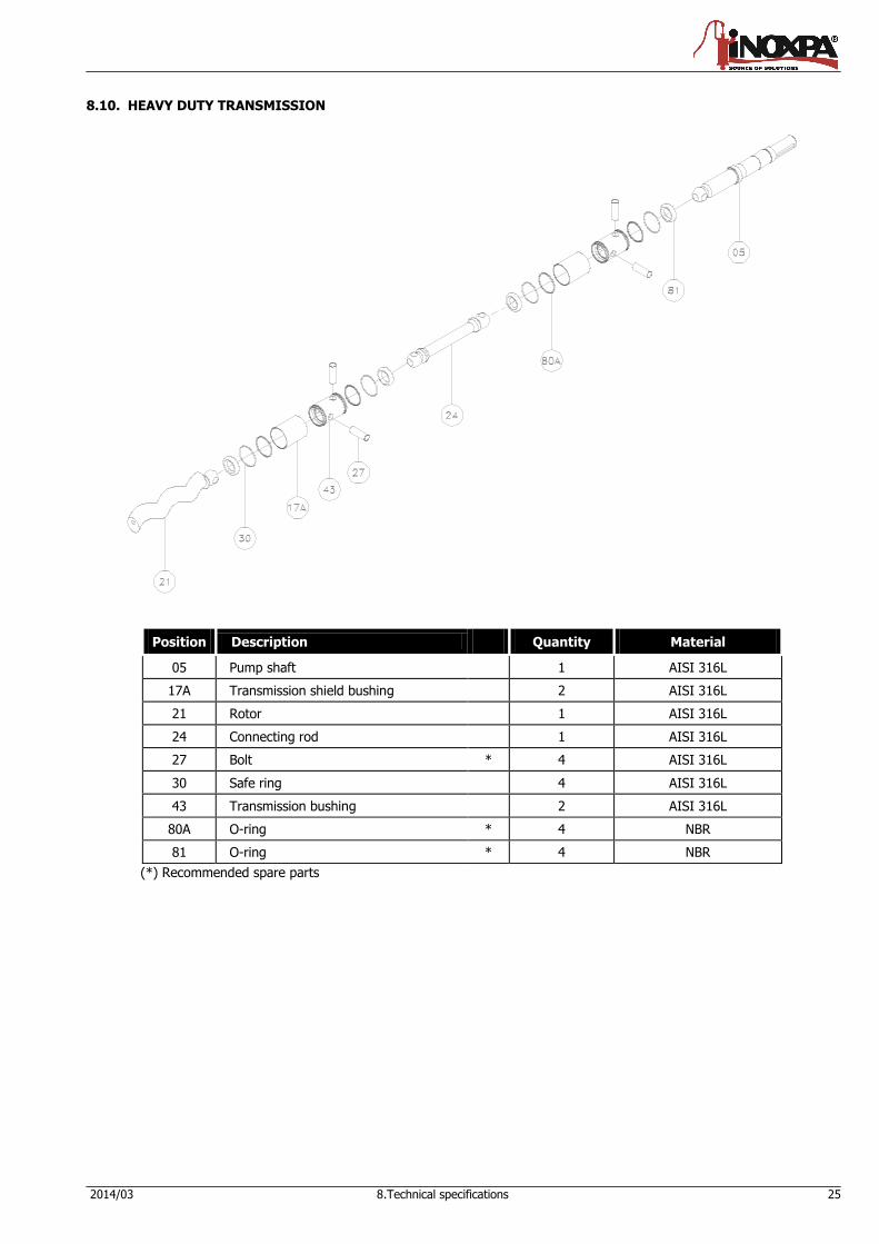
7.4.1.B Heavy duty transmission (only optional for KSF)
Disassembly Loosen the nuts (54) and remove the leg (07) and the discharge nozzle (34). Pull out the tie bars (29/29A) and then remove the stator (22); if necessary secure the rotor (21) by holding the shaft complement (26). Remove the screws (52) and the washers (53). Pull out the pump casing (01/01A) from the front side. Remove the safe rings (30), the transmission shield bushing (17A) and the bolts (27), so that the rotor (21) and one end of the connecting rod (24/24A) come out. Proceed likewise on the other end of the connecting rod in order to remove it.
Assembly Place the O-ring (81) on the pump shaft (05) / shaft complement (26) and on the connecting rod (24), and the seals (80A) on the transmission bushing (43). Place this bushing on the shaft complement (26) and place the drive bolt (27) and the bolt for the connecting rod. Place the transmission shield bushing (17A) on the bushing (43) and fasten it with the safe rings (30). Proceed likewise with the rotor on the other end of the connecting rod (21). Mount the pump casing (01) and fasten it with the screws (52) and the washers (53). Introduce the stator (22) lubricating it with soapy water and if necessary secure the rotor (21) by holding the shaft complement (26). Mount the discharge flange (34) and the leg (07) and fasten it with the nuts (54).
7.4.2. Mechanical seal
Disassembly First follow the disassembly procedure described in the preceding section. If the protections (47A) were not removed previously, remove them now. Loosen the pins (55) to remove the seal ring (31). Remove the seal cover (09) to pull out the seal at the same time as the mechanical seal (08). Finally, gently remove the stationary part of the seal, which has remained housed inside the seal cover.
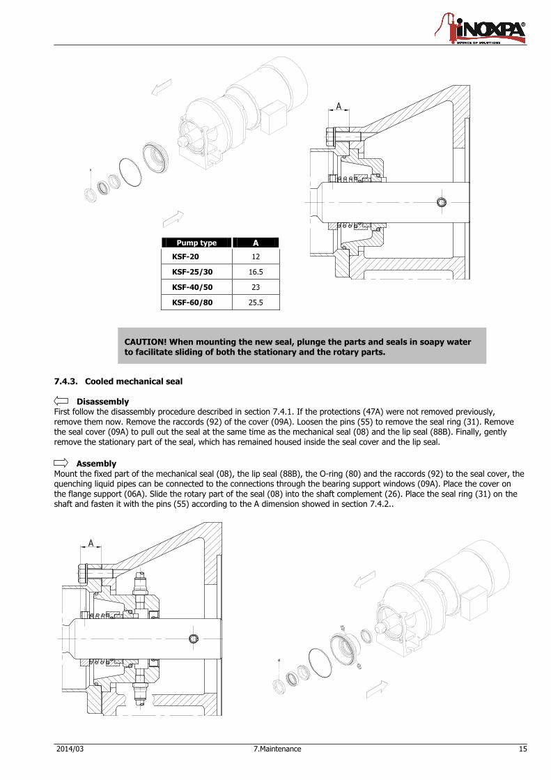
Assembly Mount the fixed part of the mechanical seal (08) and the O-ring (80) to the seal cover (09). Place the cover on the flange support (06A). Slide the rotary part of the seal (08) into the shaft complement (26). Place the seal ring (31) on the shaft and fasten it with the pins (55) according to the following assembly dimension.
2014/03 7.Maintenance 15
CAUTION! When mounting the new seal, plunge the parts and seals in soapy water to facilitate sliding of both the stationary and the rotary parts.
7.4.3. Cooled mechanical seal
Disassembly First follow the disassembly procedure described in section 7.4.1. If the protections (47A) were not removed previously,
remove them now. Remove the raccords (92) of the cover (09A). Loosen the pins (55) to remove the seal ring (31). Remove the seal cover (09A) to pull out the seal at the same time as the mechanical seal (08) and the lip seal (88B). Finally, gently remove the stationary part of the seal, which has remained housed inside the seal cover and the lip seal.
Assembly Mount the fixed part of the mechanical seal (08), the lip seal (88B), the O-ring (80) and the raccords (92) to the seal cover, the quenching liquid pipes can be connected to the connections through the bearing support windows (09A). Place the cover on the flange support (06A). Slide the rotary part of the seal (08) into the shaft complement (26). Place the seal ring (31) on the shaft and fasten it with the pins (55) according to the A dimension showed in section 7.4.2..
Pump type A
KSF-20 12
KSF-25/30 16.5
KSF-40/50 23
KSF-60/80 25.5
16 7.Maintenance 2014/03
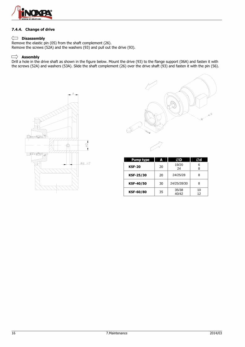
7.4.4. Change of drive
Disassembly
Remove the elastic pin (05) from the shaft complement (26). Remove the screws (52A) and the washers (93) and pull out the drive (93).
Assembly Drill a hole in the drive shaft as shown in the figure below. Mount the drive (93) to the flange support (06A) and fasten it with the screws (52A) and washers (53A). Slide the shaft complement (26) over the drive shaft (93) and fasten it with the pin (56).
Pump type A D d
KSF-20 20 19/20
24 6 8
KSF-25/30 20 24/25/28 8
KSF-40/50 30 24/25/28/30 8
KSF-60/80 35 35/38 40/42
10 12
2014/03 8.Technical specifications 17
8. Technical specifications
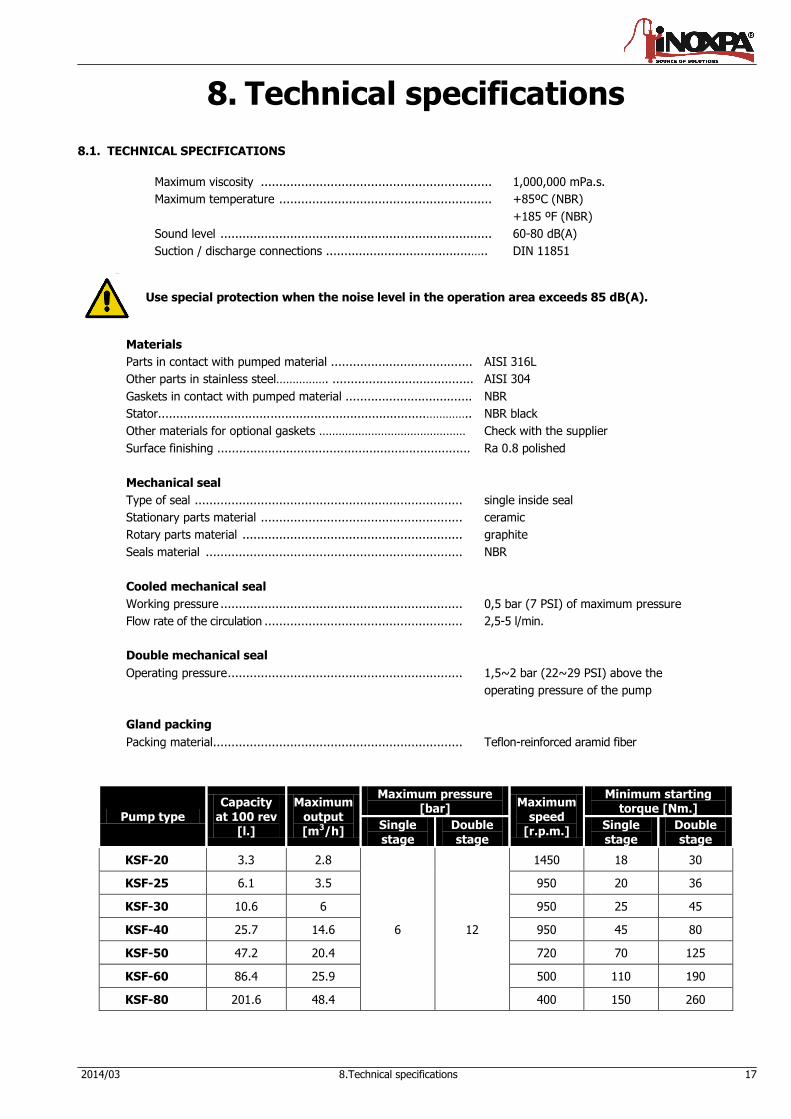
8.1. TECHNICAL SPECIFICATIONS
Maximum viscosity ............................................................... 1,000,000 mPa.s.
Maximum temperature .......................................................... +85ºC (NBR)
+185 ºF (NBR)
Sound level .......................................................................... 60-80 dB(A)
Suction / discharge connections ........................................….. DIN 11851
Use special protection when the noise level in the operation area exceeds 85 dB(A).
Materials
Parts in contact with pumped material ....................................... AISI 316L
Other parts in stainless steel……………. ....................................... AISI 304
Gaskets in contact with pumped material ................................... NBR
Stator..........................................................................………….. NBR black
Other materials for optional gaskets ……………………………………… Check with the supplier
Surface finishing ...................................................................... Ra 0.8 polished
Mechanical seal
Type of seal ......................................................................... single inside seal
Stationary parts material ....................................................... ceramic
Rotary parts material ............................................................ graphite
Seals material ...................................................................... NBR
Cooled mechanical seal
Working pressure .................................................................. 0,5 bar (7 PSI) of maximum pressure
Flow rate of the circulation ...................................................... 2,5-5 l/min.
Double mechanical seal
Operating pressure ................................................................ 1,5~2 bar (22~29 PSI) above the
operating pressure of the pump
Gland packing
Packing material.................................................................... Teflon-reinforced aramid fiber
Pump type Capacity
at 100 rev [l.]
Maximum output [m3/h]
Maximum pressure [bar]
Maximum speed
[r.p.m.]
Minimum starting torque [Nm.]
Single
stage
Double
stage
Single
stage
Double
stage
KSF-20 3.3 2.8
6 12
1450 18 30
KSF-25 6.1 3.5 950 20 36
KSF-30 10.6 6 950 25 45
KSF-40 25.7 14.6 950 45 80
KSF-50 47.2 20.4 720 70 125
KSF-60 86.4 25.9 500 110 190
KSF-80 201.6 48.4 400 150 260
18 8.Technical specifications 2014/03
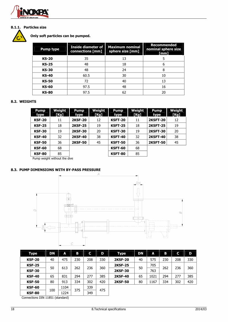
8.1.1. Particles size
Only soft particles can be pumped.
Pump type Inside diameter of connections [mm]
Maximum nominal sphere size [mm]
Recommended nominal sphere size
[mm]
KS-20 35 13 5
KS-25 48 18 6
KS-30 48 24 8
KS-40 60.5 30 10
KS-50 72 40 13
KS-60 97.5 48 16
KS-80 97.5 62 20
8.2. WEIGHTS
Pump type
Weight [Kg]
Pump type
Weight [Kg]
Pump type
Weight [Kg]
Pump type
Weight [Kg]
KSF-20 11 2KSF-20 12 KSFT-20 11 2KSFT-20 12
KSF-25 18 2KSF-25 19 KSFT-25 18 2KSFT-25 19
KSF-30 19 2KSF-30 20 KSFT-30 19 2KSFT-30 20
KSF-40 32 2KSF-40 38 KSFT-40 32 2KSFT-40 38
KSF-50 36 2KSF-50 45 KSFT-50 36 2KSFT-50 45
KSF-60 68 KSFT-60 68
KSF-80 85 KSFT-80 85
Pump weight without the dive
8.3. PUMP DIMENSIONS WITH BY-PASS PRESSURE
Type DN A B C D Type DN A B C D
KSF-20 40 475 230 208 330 2KSF-20 40 575 230 208 330
KSF-25 50 613 262 236 360
2KSF-25 50
705 262 236 360
KSF-30 2KSF-30 763
KSF-40 65 831 294 277 385 2KSF-40 65 1021 294 277 385
KSF-50 80 913 334 302 420 2KSF-50 80 1167 334 302 420
KSF-60 100
1104 375
339 475
KSF-80 1224 349
Connections DIN 11851 (standard)
2014/03 8.Technical specifications 19
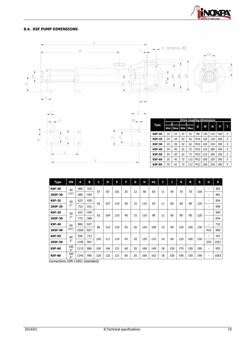
8.4. KSF PUMP DIMENSIONS
Type DN A B C D E F G H H1 I J K R S U X
KSF-20 40 1½”
489 324 57 87 101 35 12 90 83 11 45 70 70 100
- 381
2KSF-20 589 424 - 481
KSF-25 50
2”
623 439 62 107 110 40 15 110 93 11 60 90 90 120
- 504
2KSF-25 715 531 - 596
KSF-30 50 2”
623 439 62 104 110 40 15 110 96 11 60 90 90 120
- 504
2KSF-30 773 589 - 654
KSF-40 65 2½”
860 637 86 122 124 55 20 130 108 14 90 120 100 130
- 710
2KSF-40 1050 827 410 900
KSF-50 80
3”
936 713 105 117 124 55 20 130 133 14 90 120 100 130
- 767
2KSF-50 1190 967 534 1021
KSF-60 100 4”
1115 860 100 146 121 60 20 160 149 18 130 170 150 190 - 953
KSF-80 100 4”
1245 990 120 132 121 60 20 160 163 18 150 190 150 190 - 1063
Connections DIN 11851 (standard)
Type
Drive coupling dimensions
d L D M N P T
Mín Max Mín Max
KSF-20 19 24 42 52 M8 130 110 160 5
KSF-25 24 28 52 62 M10 165 130 200 5
KSF-30 24 28 52 62 M10 165 130 200 5
KSF-40 24 30 52 72 M12 215 180 250 5
KSF-50 24 30 52 72 M12 215 180 250 5
KSF-60 35 42 72 112 M12 265 230 300 5
KSF-80 35 42 72 112 M12 265 230 300 5
20 8.Technical specifications 2014/03
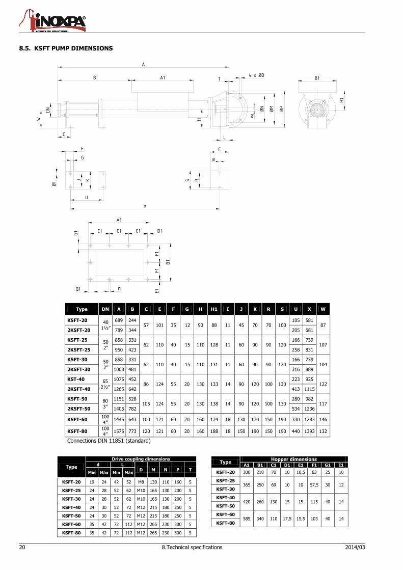
Type
Drive coupling dimensions
d L D M N P T
Mín Màx Mín Màx
KSFT-20 19 24 42 52 M8 130 110 160 5
KSFT-25 24 28 52 62 M10 165 130 200 5
KSFT-30 24 28 52 62 M10 165 130 200 5
KSFT-40 24 30 52 72 M12 215 180 250 5
KSFT-50 24 30 52 72 M12 215 180 250 5
KSFT-60 35 42 72 112 M12 265 230 300 5
KSFT-80 35 42 72 112 M12 265 230 300 5
Type Hopper dimensions
A1 B1 C1 D1 E1 F1 G1 I1
KSFT-20 300 210 70 10 10,5 63 25 10
KSFT-25 365 250 69 10 10 57,5 30 12
KSFT-30
KSFT-40 420 260 130 15 15 115 40 14
KSFT-50
KSFT-60 585 340 110 17,5 15,5 103 40 14
KSFT-80
8.5. KSFT PUMP DIMENSIONS
R
ØP
ØM
ØN
E
L
H
4 x ØDT
H1
B1
Ød
ØI
A1
A
S
X
KJ
ØI
U
A1
C1
G1
G1
B1
F1
I1
E1
C1 D1C1
F1
B
DN
W
F
G
C
Type DN A B C E F G H H1 I J K R S U X W
KSFT-20 40
1½”
689 244 57 101 35 12 90 88 11 45 70 70 100
105 581 87
2KSFT-20 789 344 205 681
KSFT-25 50 2”
858 331 62 110 40 15 110 128 11 60 90 90 120
166 739 107
2KSFT-25 950 423 258 831
KSFT-30 50 2”
858 331 62 110 40 15 110 131 11 60 90 90 120
166 739 104
2KSFT-30 1008 481 316 889
KST-40 65
2½”
1075 452 86 124 55 20 130 133 14 90 120 100 130
223 925 122
2KSFT-40 1265 642 413 1115
KSFT-50 80 3”
1151 528 105 124 55 20 130 138 14 90 120 100 130
280 982 117
2KSFT-50 1405 782 534 1236
KSFT-60 100
4” 1445 643 100 121 60 20 160 174 18 130 170 150 190 330 1283 146
KSFT-80 100
4” 1575 773 120 121 60 20 160 188 18 150 190 150 190 440 1393 132
Connections DIN 11851 (standard)
2014/03 8.Technical specifications 21
8.6. KSF PUMP
22 8.Technical specifications 2014/03
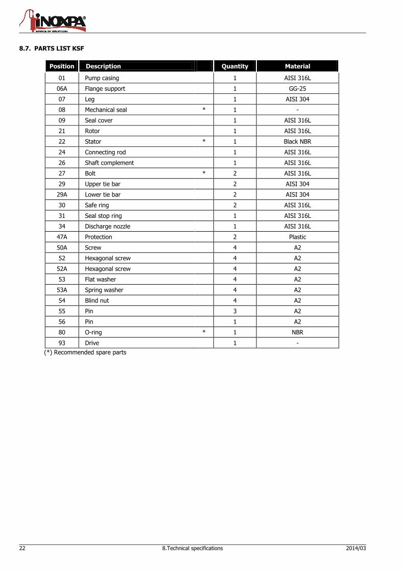
8.7. PARTS LIST KSF
Position Description Quantity Material
01 Pump casing 1 AISI 316L
06A Flange support 1 GG-25
07 Leg 1 AISI 304
08 Mechanical seal * 1 -
09 Seal cover 1 AISI 316L
21 Rotor 1 AISI 316L
22 Stator * 1 Black NBR
24 Connecting rod 1 AISI 316L
26 Shaft complement 1 AISI 316L
27 Bolt * 2 AISI 316L
29 Upper tie bar 2 AISI 304
29A Lower tie bar 2 AISI 304
30 Safe ring 2 AISI 316L
31 Seal stop ring 1 AISI 316L
34 Discharge nozzle 1 AISI 316L
47A Protection 2 Plastic
50A Screw 4 A2
52 Hexagonal screw 4 A2
52A Hexagonal screw 4 A2
53 Flat washer 4 A2
53A Spring washer 4 A2
54 Blind nut 4 A2
55 Pin 3 A2
56 Pin 1 A2
80 O-ring * 1 NBR
93 Drive 1 -
(*) Recommended spare parts
2014/03 8.Technical specifications 23
8.8. KSFT PUMP

24 8.Technical specifications 2014/03
8.9. PARTS LIST KSFT
Position Description Quantity Material
01A Pump casing 1 AISI 316L
06A Flange support 1 GG-25
07 Leg 2 AISI 304
08 Mechanical seal * 1 -
09 Seal cover 1 AISI 316L
21 Rotor 1 AISI 316L
22 Stator * 1 Black NBR
24A Feeder screw 1 AISI 316L
26 Shaft complement 1 AISI 316L
27 Bolt * 2 AISI 316L
29 Upper tie bar 2 AISI 304
29A Lower tie bar 2 AISI 304
31 Seal stop ring 1 AISI 316L
34 Discharge nozzle 1 AISI 316L
35 Bolt washer 4 AISI 316L
47A Protection 2 Plastic
50 Countersunk screw 4 A2
50A Screw 4 A2
52 Hexagonal screw 4 A2
52A Hexagonal screw 4 A2
53 Flat washer 4 A2
53A Spring washer 4 A2
54 Blind nut 4 A2
55 Pin 3 A2
56 Pin 1 A2
80 O-ring * 1 NBR
93 Drive 1 -
(*) Recommended spare parts
2014/03 8.Technical specifications 25
8.10. HEAVY DUTY TRANSMISSION
Position Description Quantity Material
05 Pump shaft 1 AISI 316L
17A Transmission shield bushing 2 AISI 316L
21 Rotor 1 AISI 316L
24 Connecting rod 1 AISI 316L
27 Bolt * 4 AISI 316L
30 Safe ring 4 AISI 316L
43 Transmission bushing 2 AISI 316L
80A O-ring * 4 NBR
81 O-ring * 4 NBR
(*) Recommended spare parts
26 8.Technical specifications 2014/03
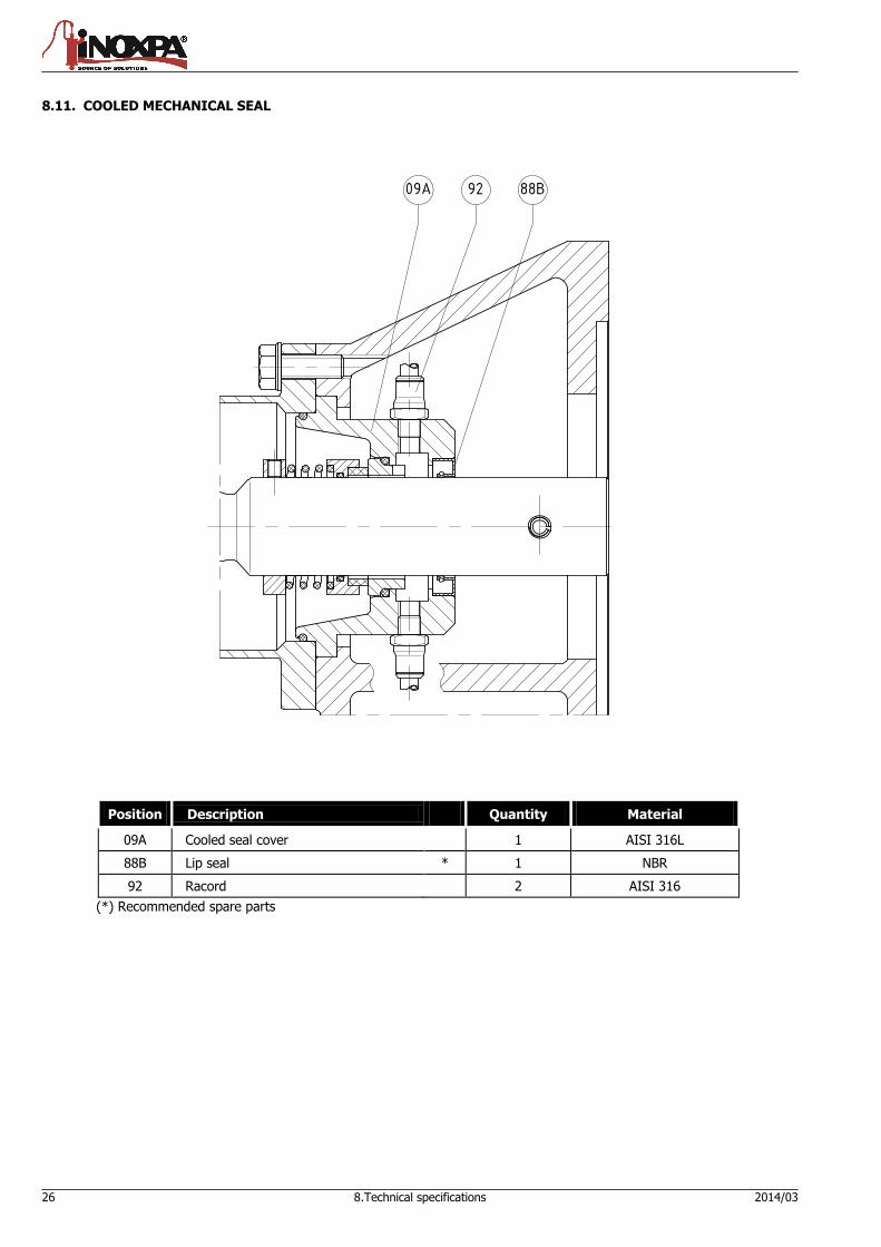
8.11. COOLED MECHANICAL SEAL
Position Description Quantity Material
09A Cooled seal cover 1 AISI 316L
88B Lip seal * 1 NBR
92 Racord 2 AISI 316
(*) Recommended spare parts
NOTES
INOXPA, S.A. DELEGACIÓN NORD-ESTE DELEGACIÓN LEVANTE
c/ Telers, 54 – PO Box 174 BARBERÀ DEL VALLÈS (BCN)
PATERNA (VALENCIA)
17820 BANYOLES (GIRONA) Tel: 937 297 280 Tel: 963 170 101
Tel: 34 972575200 Fax: 937 296 220 Fax: 963 777 539
Fax: 34 972575502 e-mail: [email protected] e-mail: [email protected]
e-mail: [email protected]
www.inoxpa.com
DELEGACIÓN STA
GALDACANO (BILBAO) LOGROÑO LA CISTÉRNIGA (VALLADOLID)
Tel: 944 572 058 Tel: 941 228 622 Tel: 983 403 197
Fax: 944 571 806 Fax: 941 204 290 Fax: 983 402 640
e-mail: [email protected] e-mail: [email protected] e-mail: [email protected]
DELEGACIÓN CENTRO DELEGACIÓN SUR
ARGANDA DEL REY (MADRID) JEREZ DE LA FRONTERA (CÁDIZ)
Tel: 918 716 084 Tel / Fax: 956 140 193
Fax: 918 703 641 e-mail: [email protected]
e-mail: [email protected]
INOXPA SOLUTIONS LEVANTE INOXPA SOLUTIONS FRANCE
PATERNA (VALENCIA) GLEIZE CHAMBLY (PARIS)
Tel: 963 170 101 Tel: 33 474627100 Tel: 33 130289100
Fax: 963 777 539 Fax: 33 474627101 Fax: 33 130289101
e-mail: [email protected] e-mail: [email protected] e-mail: [email protected]
INOXPA COLOMBIA SAS INOXPA MIDDLE EAST FZCO
INOXPA AUSTRALIA PTY (LTD)
BOGOTA DUBAI - U.A.E MORNINGTON (VICTORIA)
Tel: 571 4208711 Tel. +971 (0)4 372 4408
Tel: 61 3 5976 8881
Fax: 571 4190562 [email protected] Fax: 61 3 5976 8882
e-mail: [email protected] e-mail: [email protected]
INOXPA ALGERIE INOXPA SOUTH AFRICA (PTY) LTD INOXPA USA, Inc
ROUIBA JOHANNESBURG SANTA ROSA
Tel: 213 21856363 / 21851780 Tel: 27 117 945 223 Tel: 1 7075 853 900
Fax: 213 21854431 Fax: 27 866 807 756 Fax: 1 7075 853 908
e-mail: [email protected] e-mail: [email protected] e-mail: [email protected]
INOXPA UK LTD S.T.A. PORTUGUESA LDA INOXPA ITALIA, S.R.L.
SURREY VALE DE CAMBRA BALLO DI MIRANO – VENEZIA
Tel: 44 1737 378 060 / 079 Tel: 351 256 472 722 Tel: 39 041 411 236
Fax: 44 1737 766 539 Fax: 351 256 425 697 Fax: 39 041 5128 414
e-mail: [email protected] e-mail: [email protected] e-mail: [email protected]
INOXPA SKANDINAVIEN A/S IMPROVED SOLUTIONS PORTUGAL LDA INOXPA INDIA PVT. LTD.
HORSENS (DENMARK) VALE DE CAMBRA Maharashtra, INDIA.
Tel: 45 76 286 900 Tel: 351 256 472 140 / 138 Tel: 91 2065 008 458
Fax: 45 76 286 909 Fax: 351 256 472 130 [email protected]
e-mail: [email protected] e-mail: [email protected]
INOXPA SPECIAL PROCESSING INOXRUS
EQUIPMENT, CO., LTD. MOSCOW (RUSIA) SAINT PETERSBURG (RUSIA)
JIAXING (China) Tel / Fax: 74 956 606 020 Тel: 78 126 221 626 / 927
Tel.: 86 573 83 570 035 / 036 e-mail: [email protected]
Fax: 78 126 221 926
Fax: 86 573 83 570 038 e-mail: [email protected]
INOXPA UCRANIA
KIEV
Tel: 38 050 720 8692
e-mail: [email protected]
INOXPA products are available from our branch offices and through a network of independent distributors covering more than 50 countries around the World. For more information, visit our Web site: www.inoxpa.com This information is given for guidance only. We reserve the right to change any materials or characteristics without prior notice