Embed Size (px)
Citation preview

PSA-K960E-FS 07-3-12
Model No.: PSA-K960E-FS
Serial No.:960E-001 to 960E-009
Date Manufactured: October 2009
FOLDING STAIRWAY
Manual for Komatsu 960E Truck - Hydraulic Power Pack

FOLDING STAIRWAYKomatsu 960E Truck
Pg2PSA-K960E-FS 07-3-12
CONTENTS
Page 3 Section 1 Mounting and Installation
7 Section 2 Electrical Installation
8 Section 3 Operating Procedure
9 Section 4 Recommended Maintenance Procedure
10 Section 5 Assembly Complete-Main Assemblies
11 5-1 Assembly Complete
Parts List
12 5-2 Landing Assembly
Parts List
14 5-3 Stair Assembly
Parts List
16 5-4 Hydraulics -Cylinder Assembly
Cylinder and Components
Valve Diagram
18 5-5 Power Pack Assembly
Parts List
21 5-6 Electrical System
Wiring Diagrams
FOLDING STAIRWAYKomatsu 960E Truck
Section 1. Mounting and Installation
See Page 4
Pg3PSA-K960E-FS 07-3-12
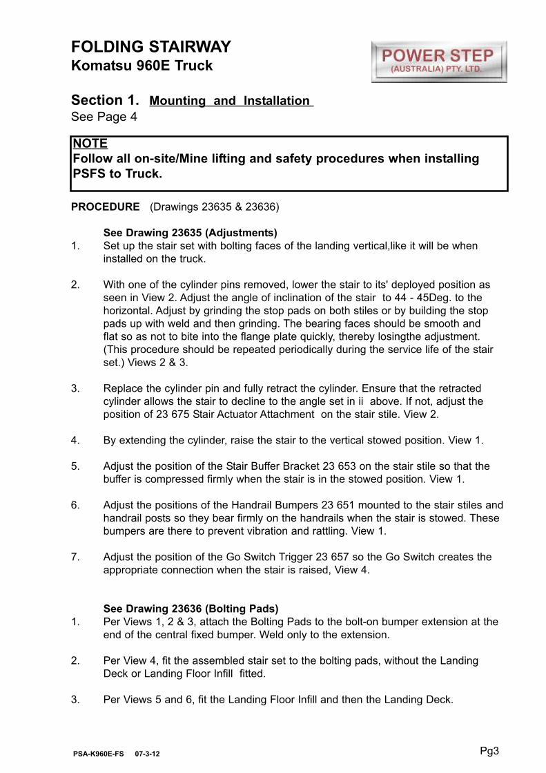
PROCEDURE (Drawings 23635 & 23636)
See Drawing 23635 (Adjustments)
1. Set up the stair set with bolting faces of the landing vertical,like it will be when
installed on the truck.
2. With one of the cylinder pins removed, lower the stair to its' deployed position as
seen in View 2. Adjust the angle of inclination of the stair to 44 - 45Deg. to the
horizontal. Adjust by grinding the stop pads on both stiles or by building the stop
pads up with weld and then grinding. The bearing faces should be smooth and
flat so as not to bite into the flange plate quickly, thereby losingthe adjustment.
(This procedure should be repeated periodically during the service life of the stair
set.) Views 2 & 3.
3. Replace the cylinder pin and fully retract the cylinder. Ensure that the retracted
cylinder allows the stair to decline to the angle set in ii above. If not, adjust the
position of 23 675 Stair Actuator Attachment on the stair stile. View 2.
4. By extending the cylinder, raise the stair to the vertical stowed position. View 1.
5. Adjust the position of the Stair Buffer Bracket 23 653 on the stair stile so that the
buffer is compressed firmly when the stair is in the stowed position. View 1.
6. Adjust the positions of the Handrail Bumpers 23 651 mounted to the stair stiles and
handrail posts so they bear firmly on the handrails when the stair is stowed. These
bumpers are there to prevent vibration and rattling. View 1.
7. Adjust the position of the Go Switch Trigger 23 657 so the Go Switch creates the
appropriate connection when the stair is raised, View 4.
See Drawing 23636 (Bolting Pads)
1. Per Views 1, 2 & 3, attach the Bolting Pads to the bolt-on bumper extension at the
end of the central fixed bumper. Weld only to the extension.
2. Per View 4, fit the assembled stair set to the bolting pads, without the Landing
Deck or Landing Floor Infill fitted.
3. Per Views 5 and 6, fit the Landing Floor Infill and then the Landing Deck.
NOTE
Follow all on-site/Mine lifting and safety procedures when installing
PSFS to Truck.

FOLDING STAIRWAYKomatsu 960E Truck
Section 1. Mounting and Installation 23635
Pg4PSA-K960E-FS 07-3-12
FOLDING STAIRWAYKomatsu 960E Truck
Section 1. Mounting and Installation 23636
Pg5PSA-K960E-FS 07-3-12
VIE
W 1
VIE
W 6
VIE
W 3
VIE
W 4
VIE
W 5
VIE
W 2
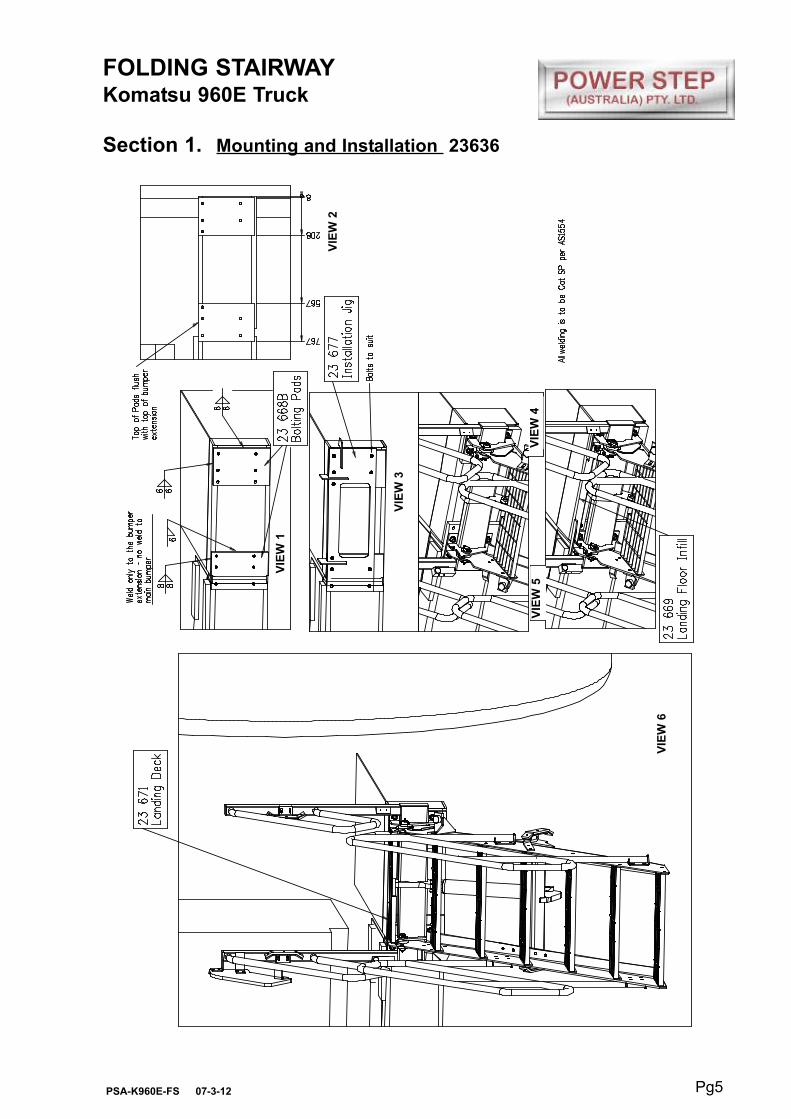
FOLDING STAIRWAYKomatsu 960E Truck
Section 1. Mounting and Installation (Dimensions) 23678
Pg6PSA-K960E-FS 07-3-12

FOLDING STAIRWAYKomatsu 960E Truck
Section 2. Electrical Installation
Pg7PSA-K960E-FS 07-3-12
Procedure
Remove centre console panel in cabin -
- to do this remove six (6) screws and gear selection knob.
Position stairway indicator panel on centre console, above hour meter.
- drill two mounting screw holes (6mm or 7/32")
- one electrical cable hole (12mm or 15/32")
- do not re-fix console Panel
Remove four (4) screws holding Komatsu fuse panel behind operator's seat. Drill one hole
to insert Caterpillar fuse holder - fit fuse holder, into fuse indicator panel - tighten. Drill
size (12mm or 15/32").
Remove rear access panel from back of cabin and run short conduit through the main
cable gland to inside centre console, ensuring conduit goes underneath control box.
Connect blue wire start from conduit above to blue wire of cabin indicator panel harness.
In rear access, connect black wire, with 10mm eye terminal to machine ground, and blue
wire to outer terminal of newly inserted fuse holder.
Install short blue wire to screw terminal of Komatsu circuit breaker, and other end to fuse
holder.
Run wiring harness from Power Step Folding Stairway magnetic proximity switch around
under radiator, and follow cabling/hose routing up to air line/ electrical outlet on rear Right
Hand Side of cabin.
Drill hole in RH Cabin access panel - route wiring harness in through access panel, and
through to under centre console - connect wires appropriately as colour coded. Hole
saw/drill size (24mm), cable tie harness as appropriate, approximately every 300mm.
To Lower Ladder (from the machine)
Position machine in a level, safe area, away from the work face, whenever possible.
Apply park brake and lower engine speed to idle.
Check that the area below the Ladder Access System is clear of people and
obstacles, and lower ladder by operating the two position electrical switch adjacent
to the ladder, to the down position by pressing the switch down.
Hold the switch in the down position until ladder is fully lowered.
If the Dozer is parked on uneven ground, the bottom of the ladder may touch the
ground before the ladder is in the fully lowered position.
Should this occur, descend the ladder with caution.
To Raise Ladder
Ascend the ladder onto the landing of the Dozer.
Ensure the area around the ladder is clear of people and standing to the side, clear
of the area the handrails and ladder raises into, operate the electrical switch to the
raise position (up).
Hold the switch in the up position until the ladder is in the fully raised position.
The ladder is now raised and stored.
FOLDING STAIRWAYKomatsu 960E Truck
Section 3. Operating Procedure
Pg8PSA-K960E-FS 07-3-12
OPERATING NOTES
NOTE: FLOW CONTROL VALVE ADJUSTMENT:
The valve should be positioned to restrict the flow and speed of the Power Step when
lowering. Adjust the knob on top of the valve by turning left or right (clockwise) when the
step is being lowered, until it is lowering at a safe and reasonable speed.
When it is adjusted, lock the adjusting knob by tightening the grub screw located on the
side of the knob.
NOTE: MAGNETIC 'GO' SWITCH ADJUSTMENT:
The switch target trigger area is located on the opposite side and end from the cable entry
point on the switch. Once it is mounted to the switch bracket, adjust the switch in or out
from the stair steel trigger point, to be within 3mm - 10mm from touching each other when
the stair is in the desired rest position.
[DO NOT EXCEED 10mm DISTANCE BETWEEN THE SWITCH AND STRIKER PLATE].
Test by raising and lowering the Power Step a couple of times and adjust again if
necessary.

FOLDING STAIRWAYKomatsu 960E Truck
Section 4. Recommended Maintenance Procedure
Daily
Visually check stairway and structure for damage, loose components,
handrails, etc.
Check for hydraulic oil leaks from hydraulic cylinders, plumbing and hoses.
Notify the appropriate supervisor for any observed damage or malfunction.
500 Hours
- Grease on regular service.
- Check daily service as above.
Pg9PSA-K960E-FS 07-3-12
FOLDING STAIRWAYKomatsu 960E Truck
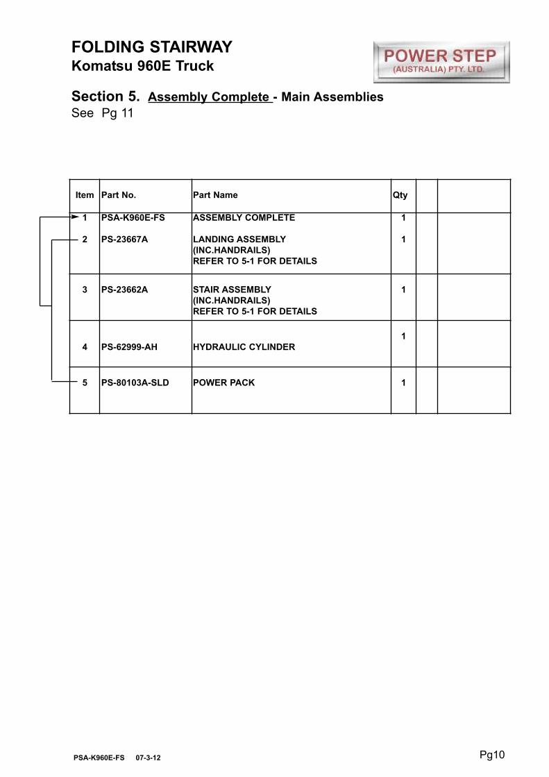
Section 5. Assembly Complete - Main Assemblies
See Pg 11
Pg10PSA-K960E-FS 07-3-12
Item Part No. Part Name Qty
1
2
PSA-K960E-FS
PS-23667A
ASSEMBLY COMPLETE
LANDING ASSEMBLY
(INC.HANDRAILS)
REFER TO 5-1 FOR DETAILS
1
1
3 PS-23662A STAIR ASSEMBLY
(INC.HANDRAILS)
REFER TO 5-1 FOR DETAILS
1
4 PS-62999-AH HYDRAULIC CYLINDER
1
5 PS-80103A-SLD POWER PACK 1

FOLDING STAIRWAY
Komatsu 960E TruckHydraulic Operation
Section 5-1 Assembly Complete PSA-K960E-FS
Pg11PSA-K960E-FS 07-3-12

FOLDING STAIRWAYKomatsu 960E Truck
Section 5-2 Landing Assembly PS 23667A
Pg12PSA-K960E-FS 07-3-12
Hydraulic Cylinder
See page 16

FOLDING STAIRWAYKomatsu 960E Truck
Section 5-2 Landing Assembly PS-23667A
Parts ListSee Drawing Pg 12
Pg13PSA-K960E-FS 07-3-12
Item Part No. Part Name Qty
1
2
3
4
5
6
7
8
9
10
11
12
13
14
15
16
17
18
19
20
21
22
23
24
25
26
27
28
29
30
PS-23667
PS-23671
PS-23673
PS-23669
PS-23651-01
PS-23668B
PS-75430
PS-23655-02
PS-23654-01
PS-23654-03
PS-23679
PS-23651-02
PS-61006-2
CPS-M16X40ZP
CPS-M16X40ZP
CPS-M16X30ZP
CPS-M10X35ZP
CPS-M10X30ZP
CPS-M10X16ZP
CPS-M8X16ZP
CPS-M6X50ZP
CPS-M6X20ZP
CPS-M5X50ZP
CPS-M10NN
CPS-M6NN
CPS-M5NZP
CPS-M16WH
CPS-M10WH
CPS-M8WH
CPS-M5WH
LANDING FRAME
LANDING DECK-STEP TREAD
HAND SHIELD
LANDING FLOOR INFILL
HANDRAIL BUMPER
BOLTING PADS-MAIN MOUNTING BLOCKS
GO- SWITCH
BUSH-(Nylon)
STAIR HINGE PIN
WASHER-(Dia 55)
SPECIAL WASHER
HANDRAIL BUMPER LINER
GREASE NIPPLE-M6 Str.
BOLT-M16 X 40 Bolt
BOLT-M16 X 40 Socket head
BOLT-M16 x 30 (For infill)
BOLT-M10 x 35
BOLT-M10 x 30
BOLT-M10 x 16
BOLT-M8 x 16
BOLT- M6 x 50 Socket head
BOLT-M6 x 20 Pan Head
BOLT - (Go Switch)
NUT-NYLOC-M10
NUT-NYLOC-M6
NUT-M5
WASHER - HARDENED - M16
WASHER - HARDENED - M10
WASHER - HARDENED - M8
FLAT WASHER- M5
1
1
1
1
2
2
2
2
2
2
8
2
2
6
2
2
6
4
4
4
2
6
4
6
8
4
2
20
4
8
FOLDING STAIRWAY
Komatsu 960E Truck
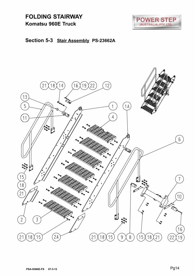
Section 5-3 Stair Assembly PS-23662A
Pg14PSA-K960E-FS 07-3-12

FOLDING STAIRWAYKomatsu 960E Truck
Section 5-3 Stair Assembly PS23662A
Parts ListSee Drawing Page 14
Pg15PSA-K960E-FS 07-3-12
Item Part No. Part Name Qty
1
1A
2
2A
3
4
5
6
7
8
9
10
11
12
13
14
15
16
17
18
19
20
21
22
PS-23662 LH
PS-23662 RH
PS-23465 LH
PS-23465 RH
PS-22266A
PS-23659
PS-23672-99
PS-23672-98
PS-23675
PS23651-01
PS-23651-02
PS-23656 LH/RH
PS-23653 LH/RH
PS-23657
PS-40002
CPS-M12X35ZP
CPS-M12X30ZP
CPS-M10X25ZP
CPS-M6X20ZP
CPS-M12NZP
CPS-M10NZP
CPS-M6NZP
CPS-M12WH
CPS-M10WH
STAIR STILES FABRICATION-LH
STAIR STILES FABRICATION-RH
STAIR EXTENSION-LH
STAIR EXTENSION-RH
STAIR TREADS
STAIR TREAD (Modified)
HANDRAIL-FRONT-INNER
HANDRAIL-REAR-OUTER
STAIR ACTUATOR ATTACHMENT
HANDRAIL BUMPER (Matched Pair)
HANDRAIL BUMPER LINER
HANDRAIL BUMPER MOUNTING(pair)
STAIR BUFFER BRACKET (Matched Pair)
GO SWITCH TRIGGER
RUBBER STOP
BOLT-M12 x 35
BOLT-M12 x 30
BOLT-M10 x 25
BOLT-M6 x 20 Pan Head
NUT-M12
NUT-M10
NUT-M6
WASHER-HARDENED-M12
WASHER-HARDENED-M10
1
1
1
1
6
1
1
1
1
2
2
2
2
2
2
12
54
8
6
66
8
8
132
16
FOLDING STAIRWAY
Komatsu 960E Truck
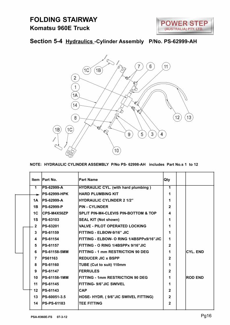
Section 5-4 Hydraulics -Cylinder Assembly P/No. PS-62999-AH
Pg16PSA-K960E-FS 07-3-12
Item Part No. Part Name Qty
1
1A
1B
1C
1S
2
3
4
5
6
7
8
9
10
11
12
13
14
PS-62999-A
PS-62999-HPK
PS-62999-A
PS-62999-P
CPS-M4X50ZP
PS-63103
PS-63201
PS-61159
PS-61154
PS-61157
PS-61158-5MM
PS61163
PS-61160
PS-61147
PS-61158-1MM
PS-61145
PS-61143
PS-60051-3.5
PS-PS-61183
HYDRAULIC CYL. (with hard plumbing )
HARD PLUMBING KIT
HYDRAULIC CYLINDER 2 1/2”
PIN - CYLINDER
SPLIT PIN-M4-CLEVIS PIN-BOTTOM & TOP
SEAL KIT (Not shown)
VALVE - PILOT OPERATED LOCKING
FITTING - ELBOW-9/16” JIC
FITTING - ELBOW- O RING 1/4BSPPx9/16”JIC
FITTING - O RING 1/4BSPPx 9/16”JIC
FITTING - 1 mm RESTRICTION 90 DEG
REDUCER JIC x BSPP
TUBE (Cut to suit) 110mm
FERRULES
FITTING - 1mm RESTRICTION 90 DEG
FITTING- 9/6”JIC SWIVEL
CAP
HOSE- HYDR. ( 9/6”JIC SWIVEL FITTING)
TEE FITTING
1
1
1
2
4
1
1
1
1
2
1
2
1
2
1
1
2
2
2
CYL. END
ROD END
NOTE: HYDRAULIC CYLINDER ASSEMBLY P/No PS- 62998-AH includes Part No.s 1 to 12

Pg17PSA-K960E-FS 07-3-12
FOLDING LADDERKomatsu 960E Truck
Section 5-4. Hydraulic Cylinder (Valve Diagram)See also Drawing page 16
Double Acting Hydraulic System with
directional Control Valve and Cylinder
Lock Valve
0.030”0.030”

FOLDING STAIRWAYKomatsu 960E Truck
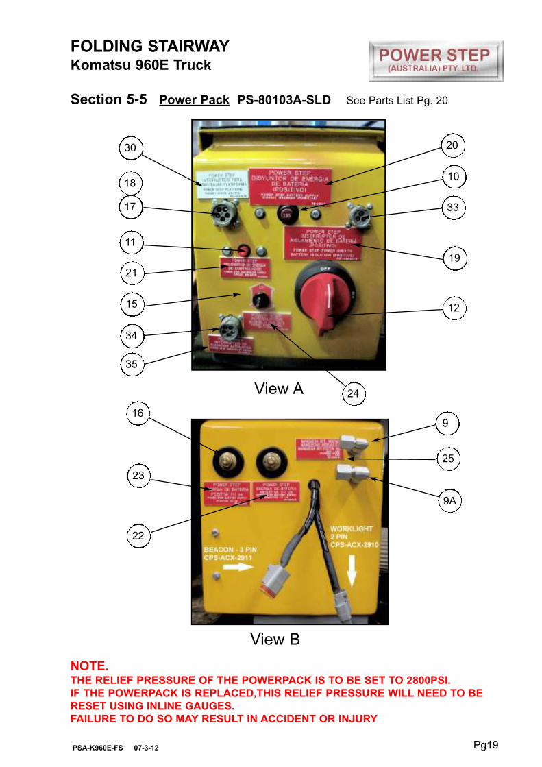
Section 5-5 Power Pack PS-80103A-SLDSee Parts List Pg. 20
Pg18PSA-K960E-FS 07-3-12
9 9A 8
4
14
29
28 6 5 27
6
2 7 7A
10
31
11
17
13
15
12
3 3226 3A8A
Hoses shown
dotted
View AView B
FOLDING STAIRWAYKomatsu 960E Truck
Section 5-5 Power Pack PS-80103A-SLD See Parts List Pg. 20
Pg19PSA-K960E-FS 07-3-12
16
23
25
9
View B
9A
View A
34
35
24
15
21
11
17
18
30
10
20
33
19
12
NOTE.THE RELIEF PRESSURE OF THE POWERPACK IS TO BE SET TO 2800PSI.
IF THE POWERPACK IS REPLACED,THIS RELIEF PRESSURE WILL NEED TO BE
RESET USING INLINE GAUGES.
FAILURE TO DO SO MAY RESULT IN ACCIDENT OR INJURY
22

Pg20PSA-K960E-FS 07-3-12
Item Part No. Part Name Qty
1
2
3
3A
4
5
6
7
7A
8
8A
9
9A
10
11
12
13
14
15
16
17
18
19
20
21
22
23
24
25
26
27
28
29
30
31
32
33
34
35
PS-80103A-SLD
PS-21107-METAL
PS-80103A
PS-80103-CLAMP
PS-82415
PS-84214
PS-82492
PS-60050-900MM 9/16”
PS-60050-900MM 7/16”
PS-61152
PS-61150
PS-61177
PS-61176
PS-84213
PS-84212
PS-84303
PS-84303-B
PS-1712080
PS-73012
PS-82493
PS-HD10-5-16P
PS-HD10-5-16S
PS-41010
PS-41011
PS-41012
PS-41013
PS-41014
PS-41023
PS-41024
PS-41041
PS-41019
PS-41017
PS-41018
PS-41016
PS-73010
PS-73009
PS-HD10-3-16P
PS-HD10-5-16P
PS-41032
POWER PACK ASSEMBLY
MOTOR ENCLOSURE- SEALED ST/ST
POWER PACK
CLAMP ELECTRIC MOTOR
AUDIBLE ALARM
BRIDGE RECTIFIER
SOLENOID 24V START MOTOR
HYDR. HOSES 9/16”JIC STRAIGHT SWIVEL
HYDR. HOSES 7/16”JIC STRAIGHT SWIVEL
HYDRAULIC FITTING 9/16”
HYDRAULIC FITTING 7/16”
HYDRAULIC FITTING 9/16”
HYDRAULIC FITTING 7/16”
135A CIRCUIT BREAKER
10A CIRCUIT BREAKER
ISOLATION SWITCH
ISOLATION SWITCH BRACKET
SEALED WIRING BOX
TOGGLE SWITCH KIT
BATTERY FEED STUDS
5 PIN SOCKET
5 PIN PLUG
DECAL-Battery Isolation
DECAL-Battery Supply C/B-135A
DECAL-Controller Supply C/B-10A
DECAL-Battery Supply-PosItive
DECAL-Battery Supply-Negative
DECAL-Up/Down
DECAL HYDRAULIC-HOSES
DECAL OIL TANK
DECAL BRIDGE RECTIFIER
DECAL SOLENOID
DECAL ALARM
DECAL RAISE/LOWER SWITCH
RUBBER BOOT RED
RUBBER BOOT BLACK
3 PIN SOCKET (PARK BREAK)
5 PIN SOCKET (AUTO-RAISE)
DECAL AUTO-RAISE SOCKET
1
1
1
1
1
1
1
1
1
1
1
1
1
1
1
1
1
1
1
2
1
1
1
1
1
1
1
1
1
1
1
1
1
1
6
3
1
1
1
FOLDING STAIRWAYKomatsu 960E Truck
Section 5-5 Power Pack PS-80103A-SLDSee Photos Pg. 18 & 19

Pg21PSA-K960E-FS 07-3-12
Cab Harness & Equipment
Refer Wiring Harness Drawings Pages 23-26
Proximity Switch AssemblyMounted on Fixed Landing
2
4
3
5
1
6 7
FOLDING STAIRWAYKomatsu 960E TruckHydraulic Operation
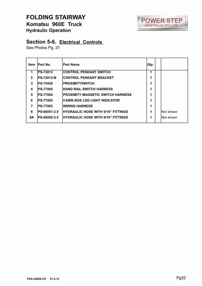
Section 5-6. Electrical Controls
Pg22PSA-K960E-FS 07-3-12
FOLDING STAIRWAYKomatsu 960E TruckHydraulic Operation
Section 5-6. Electrical Controls See Photos Pg. 21
Item Part No. Part Name Qty
1
2
3
4
5
6
7
8
8A
PS-73013
PS-73013-B
PS-75430
PS-77005
PS-77004
PS-77002
PS-77003
PS-60051-3.5
PS-60050-3.5
CONTROL PENDANT SWITCH
CONTROL PENDANT BRACKET
PROXIMITYSWITCH
HAND RAIL SWITCH HARNESS
PROXIMITY MAGNETIC SWITCH HARNESS
CABIN BOX LED LIGHT INDICATOR
WIRING HARNESS
HYDRAULIC HOSE WITH 9/16” FITTINGS
HYDRAULIC HOSE WITH 9/16” FITTINGS
1
1
1
1
1
1
1
1
1
Not shown
Not shown

Pg23PSA-K960E-FS 07-3-12
FOLDING STAIRWAYKomatsu 960E TruckHydraulic Operation
Section 5-6 - Electrical System Wiring Diagram - Pg 1
KO
M
96
0E
H
ydra
ulic
syste
m
PS
-PC
-16
77

Pg24PSA-K960E-FS 07-3-12
FOLDING STAIRWAYKomatsu 960E TruckHydraulic Operation
Section 5-6 - Electrical System Wiring Diagram - Pg 2
KO
M 9
60
EH
ydra
ulic
Opera
tion

Pg25PSA-K960E-FS 07-3-12
FOLDING STAIRWAYKomatsu 960E TruckHydraulic Operation
Section 5-6 - Electrical System Wiring Harness - Pg 3

Pg26PSA-K960E-FS 07-3-12
FOLDING STAIRWAYKomatsu 960E TruckHydraulic Operation
Section 5-6 - Electrical System Wiring Harness - Pg 4