Embed Size (px)
Citation preview

iseg Spezialelektronik GmbH Email: [email protected] Tel ++ 49 (0)351 / 26 996 - 0 Bautzner Landstr. 23 http://www.iseg-hv.com Fax ++ 49 (0)351 / 26 996 - 21 D - 01454 Radeberg/ Rossendorf
Operator’s Manual
High Voltage Power Supply of the Device Class HPS, 350 W, COMPACT

Speziale lektronik GmbH
iseg Spezialelektronik GmbH Email: [email protected] Tel ++ 49 (0)351 / 26 996 - 0 Bautzner Landstr. 23 http://www.iseg-hv.com Fax ++ 49 (0)351 / 26 996 - 21 2 D - 01454 Radeberg/ Rossendorf
Speziale lektronik GmbH
iseg Spezialelektronik GmbH Email: [email protected] Tel ++ 49 (0) 351 / 26 996 - 0 Bautzner Landstr. 23 http://www.iseg-hv.com Fax ++ 49 (0) 351 / 26 996 - 21 D - 01454 Radeberg/ Rossendorf 3
Attention
It is strongly recommended to read the manual before operation!
To avoid the possibility of lethal shock to the operator, the unit must not be operated with the cover removed.
There are no user maintainable parts inside the power supply!
The mains connector is equipped with basic insulation and a protective earth conductor. The unit may only be operated with protective earth conductor connected.
We decline all responsibility for damages and injuries caused by an improper use of the device. It is strongly recommended to read the manual before operation!
All information in this document is subject to change without notice. We take no responsibility for any error in this document. We reserve the right to make changes in the product design without any notification to the users.
Warning! notes in the text call attention to hazards in operation of these units that could lead to possible injury or death.
Caution! notes in the text indicate procedures to be followed to avoid possible damage to equipment.
Note! notes in the text indicate procedures to be followed to avoid possible damage to equipment.
Revision: 2016-01-25_eng

Speziale lektronik GmbH
iseg Spezialelektronik GmbH Email: [email protected] Tel ++ 49 (0)351 / 26 996 - 0 Bautzner Landstr. 23 http://www.iseg-hv.com Fax ++ 49 (0)351 / 26 996 - 21 4 D - 01454 Radeberg/ Rossendorf
Table of Contents
1 Safety instructions ........................................................................................................................................................... 7 2 Device description ........................................................................................................................................................... 8
2.1 Short description ..................................................................................................................................................... 8 2.2 Technical Data ........................................................................................................................................................ 9 2.3 Electrical wiring of the high voltage output ............................................................................................................ 10 2.4 Dimensions ........................................................................................................................................................... 11
3 Functional description.................................................................................................................................................... 12 3.1 Operating states.................................................................................................................................................... 12 3.2 Operating mode .................................................................................................................................................... 13 3.3 Monitoring ............................................................................................................................................................. 13 3.4 ARC-Management ................................................................................................................................................ 14 3.5 Interlock ................................................................................................................................................................ 15
4 Pinout ............................................................................................................................................................................ 16 4.1 Supply ................................................................................................................................................................... 16 4.2 HV connection....................................................................................................................................................... 16 4.3 Return connection (HV ground) ............................................................................................................................ 16 4.4 USB - / RS-232 - connection................................................................................................................................. 16 4.5 IL connection......................................................................................................................................................... 16 4.6 CAN connection .................................................................................................................................................... 16 4.7 Ethernet connection .............................................................................................................................................. 16
5 Front panel operation..................................................................................................................................................... 17 5.1 Display .................................................................................................................................................................. 17 5.2 Menu setting ......................................................................................................................................................... 18 5.3 Menu structure ...................................................................................................................................................... 18
6 Interface control ............................................................................................................................................................. 20 6.1 Description of the RS-232- / USB interface........................................................................................................... 20 6.2 Description of the CAN interface........................................................................................................................... 21 6.3 Description of the Ethernet interface..................................................................................................................... 22
7 SCPI command set with EDCP...................................................................................................................................... 25 7.1 Introduction ........................................................................................................................................................... 25 7.2 Output formats for voltage and current:................................................................................................................. 27 7.3 Channel status (read access) ............................................................................................................................... 29 7.4 ChannelEventStatus (read/write access) .............................................................................................................. 30 7.5 ModuleStatus (read access)) ................................................................................................................................ 31 7.6 ModuleEventStatus (read/write access)................................................................................................................ 31
8 Further Command Sets ................................................................................................................................................. 32 9 Error............................................................................................................................................................................... 32
9.1 Error acknowledgement ........................................................................................................................................ 32 9.2 Error messages on the LC-Display ....................................................................................................................... 32 9.3 Further Errors........................................................................................................................................................ 32
10 Maintenance.............................................................................................................................................................. 32
Speziale lektronik GmbH
iseg Spezialelektronik GmbH Email: [email protected] Tel ++ 49 (0) 351 / 26 996 - 0 Bautzner Landstr. 23 http://www.iseg-hv.com Fax ++ 49 (0) 351 / 26 996 - 21 D - 01454 Radeberg/ Rossendorf 5
List of figures Figure 2.1: Electrical wiring of the high voltage output............................................................................................................ 10 Figure 2.2: Dimensioned drawing (in mm) .............................................................................................................................. 11 Figure 3.1: Operating area of the device ................................................................................................................................ 12 Figure 3.2: Power reduction vs. input voltage......................................................................................................................... 14 Figure 3.3: enable ARC counting............................................................................................................................................ 14 Figure 3.4: disable ARC counting ........................................................................................................................................... 15 Figure 4.1: Front panel of the device ...................................................................................................................................... 16 Figure 5.1: Front panel with rotary encoder and display (LCD)............................................................................................... 17 Figure 5.2: Set value of voltage and current ........................................................................................................................... 17 Figure 5.3: Dispaly during high voltage generation................................................................................................................. 18 Figure 5.4: Visualization of the main menu............................................................................................................................. 18 Figure 6.1: Ethernet configuration .......................................................................................................................................... 22 Figure 6.2: Lantronix configuration program ........................................................................................................................... 22

Speziale lektronik GmbH
iseg Spezialelektronik GmbH Email: [email protected] Tel ++ 49 (0)351 / 26 996 - 0 Bautzner Landstr. 23 http://www.iseg-hv.com Fax ++ 49 (0)351 / 26 996 - 21 6 D - 01454 Radeberg/ Rossendorf
List of tables
Table 2.1: Technical data, device claaa ................................................................................................................................... 9 Table 2.2: Continuation: technical data, device class ............................................................................................................. 10 Table 3.1: Description special operating states ...................................................................................................................... 13 Table 3.2: Factory settings of the ARC Management. ............................................................................................................ 15 Table 5.1: Main menu............................................................................................................................................................. 18 Table 5.2: Submenu “Set points“ ............................................................................................................................................ 18 Table 5.3: Submenu “Device Settings“ ................................................................................................................................... 19 Table 5.4: Submenu “ARC Management“ .............................................................................................................................. 19 Table 5.5: Submenu “Device Data“ ........................................................................................................................................ 19 Table 6.1: Electrical wiring of the RS232 Interface ................................................................................................................. 20 Table 6.2: Programming seriell interface ................................................................................................................................ 21 Table 6.3: Pinout CAN interface ............................................................................................................................................. 21 Table 6.4: Factory Ethernet settings....................................................................................................................................... 23 Table 6.5: Principle sequence of communication between PC and HV unit ........................................................................... 23 Table 7.1: SCPI command set with EDCP ............................................................................................................................. 25 Table 7.2: continuation command set with EDCP................................................................................................................... 26 Table 7.3: continuation command set with EDCP................................................................................................................... 27 Table 7.4: Output format for voltage....................................................................................................................................... 27 Table 7.5: Output format for current ....................................................................................................................................... 27 Table 7.6: channel status register........................................................................................................................................... 29 Table 7.7: Explanation of individual bits of the cannel status Registers ................................................................................. 29 Table 7.8: Channal Event Status Register.............................................................................................................................. 30 Table 7.9: Explanation of individual bits of the cannel event status registers ......................................................................... 30 Table 7.10: Module Status Register ....................................................................................................................................... 31 Table 7.11: Explanation of the individual bits of the module status Registers ........................................................................ 31 Table 7.12: Module Event Status Register ............................................................................................................................. 31 Table 7.13: Explanation of the individual bits of the module status event Registers............................................................... 31 Table 9.1: Error messages on the LC-Display........................................................................................................................ 32 Table 9.2: Further Errors ........................................................................................................................................................ 32

Speziale lektronik GmbH
iseg Spezialelektronik GmbH Email: [email protected] Tel ++ 49 (0) 351 / 26 996 - 0 Bautzner Landstr. 23 http://www.iseg-hv.com Fax ++ 49 (0) 351 / 26 996 - 21 D - 01454 Radeberg/ Rossendorf 7
1 Safety instructions It is strongly recommended to read the operator’s manual before operation.
Warning! To avoid the possibility of lethal shock to the operator, the unit must not be operated with the cover removed! There are no user maintainable parts inside the power supply!
Warning! Before operations at the load or the high voltage output of the power supply are started, the device has to be switched off, the discharge of residual voltage has to be finished and the high voltage output of the power supply must be properly grounded. Depending on application residiual voltages can be present for long time periods. These residiual voltages can lead to severe injuries.
We decline all responsibility for damages and injuries caused by an improper use of the device. It is strongly recommended to read the manual before operation!
This High Voltage Power Supply has to be installed by trained and qualified personnel only.
Following instructions are made for the personal safety of the operator, the safe use of this product and the connected devices.
Warning! High voltage power supplies of the device class HPS, 350 W, COMPACT are supplied from single phase mains voltage and generate an output voltage up to 70 kV. The disregard of this voltage condition can cause death, heavy injuries or material damage.
Before connecting to the local mains it must be made sure that the nominal line voltage of this unit matches to the local mains
The power input has to be fused with not less than 6.3 A, with slow delay.
After system assembly the connections with the protective ground have to be checked for proper connection!
The HV cable has to be connected to the load properly and isolated according to proof-voltage.
The shield of the HV cable is always connected to the housing.
An air flow rate of 70 m³/h has to be guaranteed under any circumstances. Therefore do not cover any air input or output slots.
The unit is prepared to be mounted into a 19“-cabinet with help of screws on the fastening points (thread M4, thread length 5 mm). In this case the necessary air flow conditions through the according air input and output slots have to be guaranteed.
If the unit will be used as desk top instrument then the enclosed unit bases have to be glued on the bottom in order to guarantee a certain distance to the desk.
The unit can be operated with an ambient temperature of 0°C to 50°C.
Warning! When operating with an ambient temperature above 35°C the temperature of the mains switch and the front panel may rise above 45°C!
Speziale lektronik GmbH
iseg Spezialelektronik GmbH Email: [email protected] Tel ++ 49 (0)351 / 26 996 - 0 Bautzner Landstr. 23 http://www.iseg-hv.com Fax ++ 49 (0)351 / 26 996 - 21 8 D - 01454 Radeberg/ Rossendorf
2 Device description
2.1 Short description
High voltage power supplies of the device class HPS, 350 W, COMPACT are supplied from single phase mains voltage and generates an output voltage up to 70 kV as well as an output current up to 350 mA.
The device can be controlled via:
• front panel operation with rotary encoder and display or
• digital interfaces.
Main characteristics:
• best control characteristics
• multiple interface options
• front panel control with LCD
• capacitor charger (optional CLD)
• very low ripple and noise, very low EMI
• ARC Management
Speziale lektronik GmbH
iseg Spezialelektronik GmbH Email: [email protected] Tel ++ 49 (0) 351 / 26 996 - 0 Bautzner Landstr. 23 http://www.iseg-hv.com Fax ++ 49 (0) 351 / 26 996 - 21 D - 01454 Radeberg/ Rossendorf 9
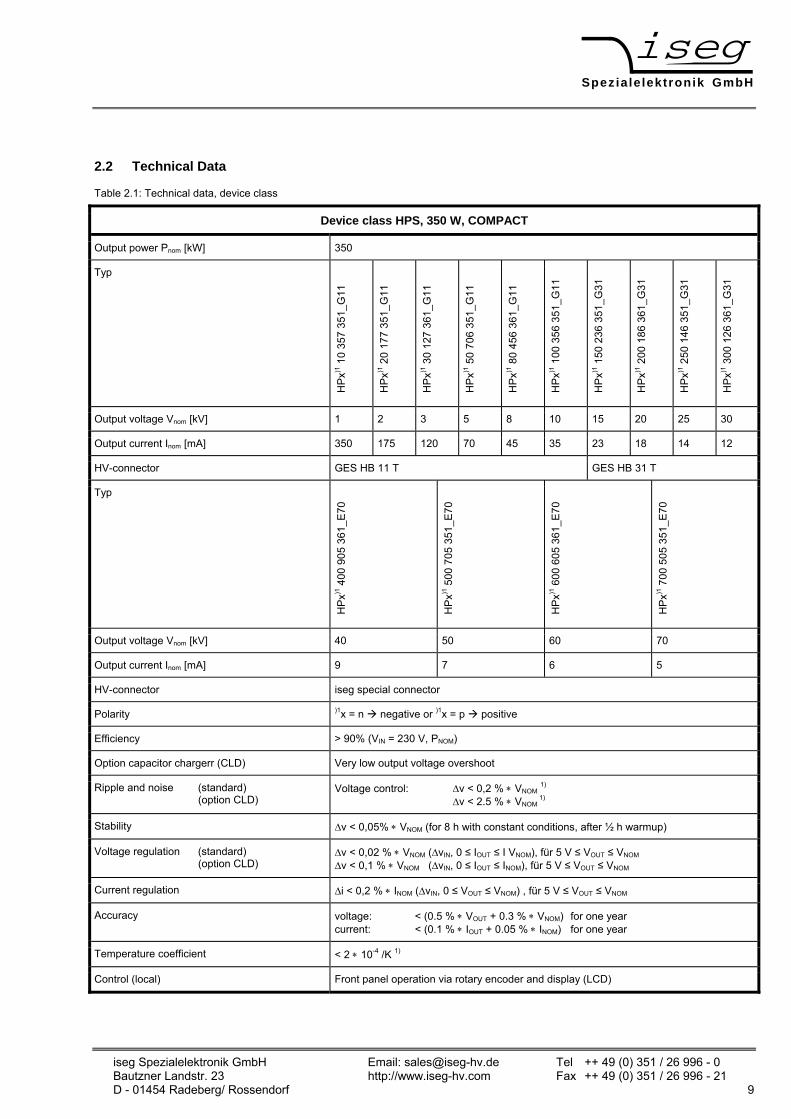
2.2 Technical Data
Table 2.1: Technical data, device class
Device class HPS, 350 W, COMPACT
Output power Pnom [kW] 350
Typ
HP
x)1 1
0 35
7 35
1_G
11
HP
x)1 2
0 17
7 35
1_G
11
HP
x)1 3
0 12
7 36
1_G
11
HP
x)1 5
0 70
6 35
1_G
11
HP
x)1 8
0 45
6 36
1_G
11
HP
x)1 1
00 3
56 3
51_G
11
HP
x)1 1
50 2
36 3
51_G
31
HP
x)1 2
00 1
86 3
61_G
31
HP
x)1 2
50 1
46 3
51_G
31
HP
x)1 3
00 1
26 3
61_G
31
Output voltage Vnom [kV] 1 2 3 5 8 10 15 20 25 30
Output current Inom [mA] 350 175 120 70 45 35 23 18 14 12
HV-connector GES HB 11 T GES HB 31 T
Typ
HP
x)1 4
00 9
05 3
61_E
70
HP
x)1 5
00 7
05 3
51_E
70
HP
x)1 6
00 6
05 3
61_E
70
HP
x)1 7
00 5
05 3
51_E
70
Output voltage Vnom [kV] 40 50 60 70
Output current Inom [mA] 9 7 6 5
HV-connector iseg special connector
Polarity )1x = n negative or )1x = p positive
Efficiency > 90% (VIN = 230 V, PNOM)
Option capacitor chargerr (CLD) Very low output voltage overshoot
Ripple and noise (standard) (option CLD)
Voltage control: ∆v < 0,2 % ∗ VNOM 1)
∆v < 2.5 % ∗ VNOM 1)
Stability ∆v < 0,05% ∗ VNOM (for 8 h with constant conditions, after ½ h warmup)
Voltage regulation (standard) (option CLD)
∆v < 0,02 % ∗ VNOM (∆vIN, 0 ≤ IOUT ≤ I VNOM), für 5 V ≤ VOUT ≤ VNOM
∆v < 0,1 % ∗ VNOM (∆vIN, 0 ≤ IOUT ≤ INOM), für 5 V ≤ VOUT ≤ VNOM
Current regulation ∆i < 0,2 % ∗ INOM (∆vIN, 0 ≤ VOUT ≤ VNOM) , für 5 V ≤ VOUT ≤ VNOM
Accuracy voltage: < (0.5 % ∗ VOUT + 0.3 % ∗ VNOM) for one year current: < (0.1 % ∗ IOUT + 0.05 % ∗ INOM) for one year
Temperature coefficient < 2 ∗ 10-4 /K 1)
Control (local) Front panel operation via rotary encoder and display (LCD)
Speziale lektronik GmbH
iseg Spezialelektronik GmbH Email: [email protected] Tel ++ 49 (0)351 / 26 996 - 0 Bautzner Landstr. 23 http://www.iseg-hv.com Fax ++ 49 (0)351 / 26 996 - 21 10 D - 01454 Radeberg/ Rossendorf
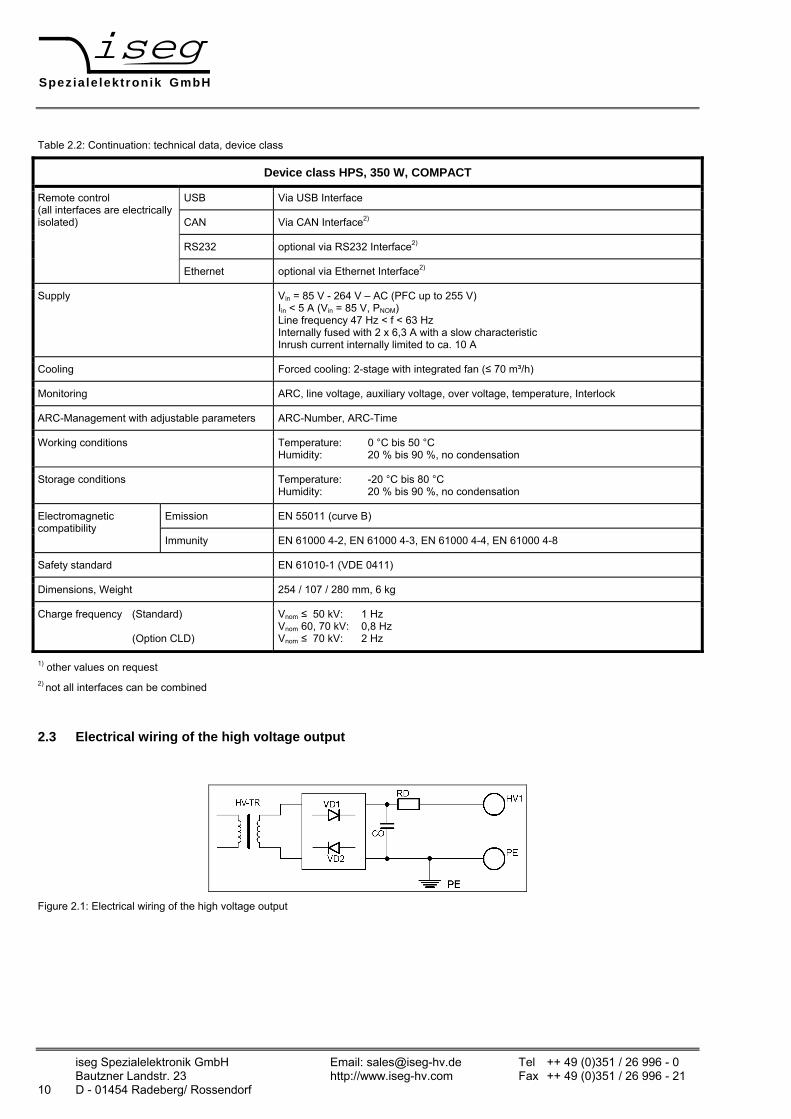
Table 2.2: Continuation: technical data, device class
Device class HPS, 350 W, COMPACT
USB Via USB Interface
CAN Via CAN Interface2)
RS232 optional via RS232 Interface2)
Remote control (all interfaces are electrically isolated)
Ethernet optional via Ethernet Interface2)
Supply Vin = 85 V - 264 V – AC (PFC up to 255 V) Iin < 5 A (Vin = 85 V, PNOM) Line frequency 47 Hz < f < 63 Hz Internally fused with 2 x 6,3 A with a slow characteristic Inrush current internally limited to ca. 10 A
Cooling Forced cooling: 2-stage with integrated fan (≤ 70 m³/h)
Monitoring ARC, line voltage, auxiliary voltage, over voltage, temperature, Interlock
ARC-Management with adjustable parameters ARC-Number, ARC-Time
Working conditions Temperature: 0 °C bis 50 °C Humidity: 20 % bis 90 %, no condensation
Storage conditions Temperature: -20 °C bis 80 °C Humidity: 20 % bis 90 %, no condensation
Emission EN 55011 (curve B) Electromagnetic compatibility
Immunity EN 61000 4-2, EN 61000 4-3, EN 61000 4-4, EN 61000 4-8
Safety standard EN 61010-1 (VDE 0411)
Dimensions, Weight 254 / 107 / 280 mm, 6 kg
Charge frequency (Standard) (Option CLD)
Vnom ≤ 50 kV: 1 Hz Vnom 60, 70 kV: 0,8 Hz Vnom ≤ 70 kV: 2 Hz
1) other values on request 2) not all interfaces can be combined
2.3 Electrical wiring of the high voltage output
Figure 2.1: Electrical wiring of the high voltage output
Speziale lektronik GmbH
iseg Spezialelektronik GmbH Email: [email protected] Tel ++ 49 (0) 351 / 26 996 - 0 Bautzner Landstr. 23 http://www.iseg-hv.com Fax ++ 49 (0) 351 / 26 996 - 21 D - 01454 Radeberg/ Rossendorf 11
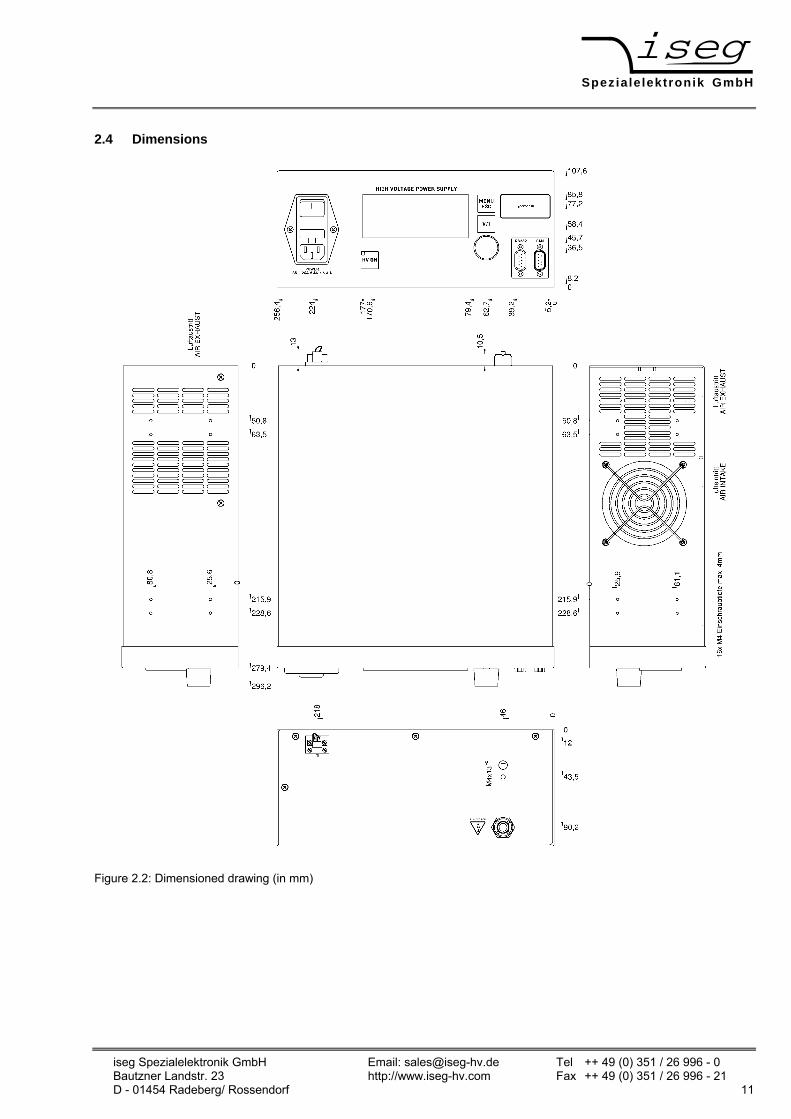
2.4 Dimensions
Figure 2.2: Dimensioned drawing (in mm)

Speziale lektronik GmbH
iseg Spezialelektronik GmbH Email: [email protected] Tel ++ 49 (0)351 / 26 996 - 0 Bautzner Landstr. 23 http://www.iseg-hv.com Fax ++ 49 (0)351 / 26 996 - 21 12 D - 01454 Radeberg/ Rossendorf
3 Functional description
In the following, the working principle of the power supply will be described.
Next to the mains there is a EMI/RFI filter, which feeds the power factor correction unit (PFC) and the inrush current limitation circuit. The PFC draws sinusoidal currents from the mains, which are in phase with the supply voltage.
Atention! If input voltage is higher than 255 V, the PFC is working as a rectifier only and power consumption is not sinusoidal in this case. If input voltage is lower than 100 V either output power or ambient temperature have to be decreased (Figure 3.2).
The PFC provides a DC link voltage, which is buffered by an electrolytic capacitor battery. An inverter with a connected resonance circuit transforms the DC-Link voltage into a controllable sinusoidal voltage. The HV-transformer and HV-rectifier provide an output voltage corresponding to the external Set-voltage. Output voltage and current are measured by high precision voltage dividers and a shunt and are fed back to the control circuit. A damping resistor connected to the output capacitance limits the output current during a load change or ARC.
.The control circuit controls and limits the output voltage and current corresponding to the set values. Normalized monitor voltages for voltage and current are provided for read back. The control circuit is also monitoring the input voltages, auxiliary voltages and the temperatures of cooling air and single components.
The power supply is turned ON/OFF with a switch installed at the front panel of the power supply.
An ARC-management with adjustable parameters is installed in the power supply. The ARC-management parameters can be set via the digital interfaces or the front panel.
3.1 Operating states
Figure 2.1 shows the operating area of the device. There are two modes for high voltage generation:
1. Constant voltage control CV:
Control of output voltage according to its set value under the condition measured output current (IMEAS ) < set value output current (ISET).
2. Constant current control CC :
Control of output current according to its set value under the condition measured output voltage (VMEAS ) < set value output voltage (VSET).
Output voltage
Output current
Vnom
Inom
0
Pnom
Operating area
Figure 3.1: Operating area of the device
Speziale lektronik GmbH
iseg Spezialelektronik GmbH Email: [email protected] Tel ++ 49 (0) 351 / 26 996 - 0 Bautzner Landstr. 23 http://www.iseg-hv.com Fax ++ 49 (0) 351 / 26 996 - 21 D - 01454 Radeberg/ Rossendorf 13
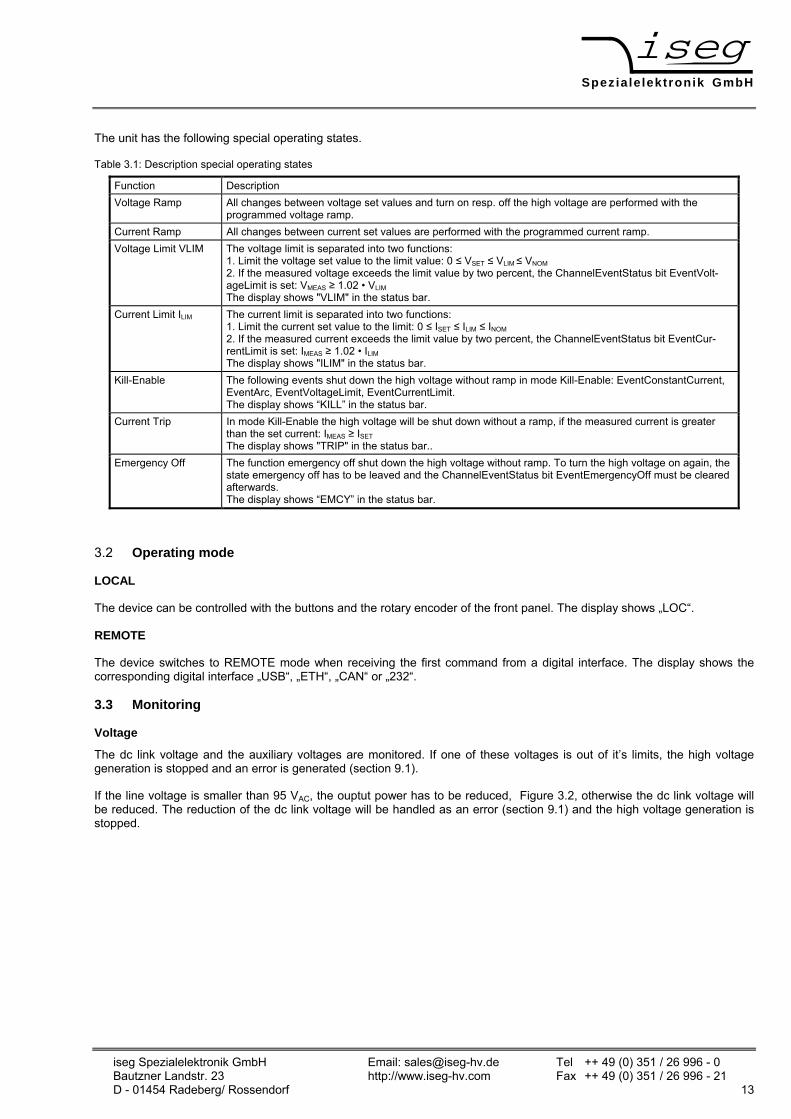
The unit has the following special operating states.
Table 3.1: Description special operating states
Function Description Voltage Ramp All changes between voltage set values and turn on resp. off the high voltage are performed with the
programmed voltage ramp. Current Ramp All changes between current set values are performed with the programmed current ramp. Voltage Limit VLIM The voltage limit is separated into two functions:
1. Limit the voltage set value to the limit value: 0 ≤ VSET ≤ VLIM ≤ VNOM 2. If the measured voltage exceeds the limit value by two percent, the ChannelEventStatus bit EventVolt-ageLimit is set: VMEAS ≥ 1.02 • VLIM The display shows "VLIM" in the status bar.
Current Limit ILIM The current limit is separated into two functions: 1. Limit the current set value to the limit: 0 ≤ ISET ≤ ILIM ≤ INOM 2. If the measured current exceeds the limit value by two percent, the ChannelEventStatus bit EventCur-rentLimit is set: IMEAS ≥ 1.02 • ILIM The display shows "ILIM" in the status bar.
Kill-Enable The following events shut down the high voltage without ramp in mode Kill-Enable: EventConstantCurrent, EventArc, EventVoltageLimit, EventCurrentLimit. The display shows “KILL” in the status bar.
Current Trip In mode Kill-Enable the high voltage will be shut down without a ramp, if the measured current is greater than the set current: IMEAS ≥ ISET The display shows "TRIP" in the status bar..
Emergency Off The function emergency off shut down the high voltage without ramp. To turn the high voltage on again, the state emergency off has to be leaved and the ChannelEventStatus bit EventEmergencyOff must be cleared afterwards. The display shows “EMCY” in the status bar.
3.2 Operating mode
LOCAL
The device can be controlled with the buttons and the rotary encoder of the front panel. The display shows „LOC“.
REMOTE
The device switches to REMOTE mode when receiving the first command from a digital interface. The display shows the corresponding digital interface „USB“, „ETH“, „CAN“ or „232“.
3.3 Monitoring
Voltage
The dc link voltage and the auxiliary voltages are monitored. If one of these voltages is out of it’s limits, the high voltage generation is stopped and an error is generated (section 9.1).
If the line voltage is smaller than 95 VAC, the ouptut power has to be reduced, Figure 3.2, otherwise the dc link voltage will be reduced. The reduction of the dc link voltage will be handled as an error (section 9.1) and the high voltage generation is stopped.

Speziale lektronik GmbH
iseg Spezialelektronik GmbH Email: [email protected] Tel ++ 49 (0)351 / 26 996 - 0 Bautzner Landstr. 23 http://www.iseg-hv.com Fax ++ 49 (0)351 / 26 996 - 21 14 D - 01454 Radeberg/ Rossendorf
Input voltage (VAC)
Output power %
0
85 90 95 100 260 265
100
95
90
85
75
80
Figure 3.2: Power reduction vs. input voltage
Temperature
Temperature is monitored at several points within the unit. High voltage generation is stopped in case of external air temperature exceeds 50°C or internal temperature of several modules exceeds a predefined limiting value.
In this case an error is generated (see section 9.1).
3.4 ARC-Management
The HV power supply is equipped with an ARC Management with adjustable parameters. The ARC Management can be adjusted with the front panel or with the digital interfaces.
An ARC is defined, if the output current IOUT ≥ 1.5 . ISET.
The functionality of the ARC Management can be divided in three operating states:
1. KillEnable active
• High voltage shuts down after the first ARC
2. Enable ARC counting
• The high voltage is restored immediately after every ARC,
• The ARCs are counted,
• The high voltage is shut down if the allowed number of ARCs (ARC-Number) in a specific time (ARC-Time) is exceeded
• In this case the ChannelEventStatus Bit EventArcError is set
Vout
t
ARC1 ARC2 ARC-Number...
ARC-Time
HV shut down when exceeding ARC-Number within ARC-Time
Figure 3.3: enable ARC counting

Speziale lektronik GmbH
iseg Spezialelektronik GmbH Email: [email protected] Tel ++ 49 (0) 351 / 26 996 - 0 Bautzner Landstr. 23 http://www.iseg-hv.com Fax ++ 49 (0) 351 / 26 996 - 21 D - 01454 Radeberg/ Rossendorf 15
3. Disable ARC counting
• High voltage is shut down after every ARC,
• After the ARC wait time ARC-Wait high voltage is ramped to the set voltage with the ARC-Ramp,
• RC-Wait and ARC-Ramp are factory fixed to avoid damage due to permanent ARCs
Vout
t
ARC1 ARC2 ARC(n)...
ARC-Wait ARC-Ramp
ARC(n+1)
...
Figure 3.4: disable ARC counting
The factory settings of the ARC Management are:
Table 3.2: Factory settings of the ARC Management.
ARC counting Disabled ARC-Number 1 ARC-Time Depends on the nominal output voltage (typical: < 10 s) ARC-Wait Depends on the nominal output voltage (typical: < 1 s) ARC-Ramp Depends on the nominal output voltage (typical: 5.Vnom/s)
3.5 Interlock
The power supply is equipped with a connector “IL” for a hardware safety loop (interlock, maximum cross section area 1.5mm²) at the back side.
If the loop is closed an internal current source (open circuit voltage 15 V / short circuit current max. 40 mA) will drive a current of ca. 12 mA through a built-in mechanical relays (certified in accordance with IEC/EN 60950 and UL 60950, fulfils the Telcordia requirements according GR 1089 and FCC part 68).
The impedance of the closed loop must be less than 300 Ohm.
If the safety loop is open (Impedance > 100 kOhm), the relays will open. The high voltage generation is stopped only by the opened relay contacts. The relay locks the gate pulses of the semiconductors of the inverter.
Warning! The internal and external capacitances must be discharge by the load before the output will be voltage-free. The internal discharge resistors have a high resistance, so a very long discharging time is possible according to the connected load.
The unit is not equipped with an active discharging circuit! Before operations at the load or the high voltage output of the power supply are started, the high voltage output of the power supply must be properly grounded.
It is not possible to switch on the high voltage generation if the safety loop is open.
The state of the opened safety loop is handled as an error. For releasing the high voltage generation the closed safety loop has to be approved. (section 9.1).

Speziale lektronik GmbH
iseg Spezialelektronik GmbH Email: [email protected] Tel ++ 49 (0)351 / 26 996 - 0 Bautzner Landstr. 23 http://www.iseg-hv.com Fax ++ 49 (0)351 / 26 996 - 21 16 D - 01454 Radeberg/ Rossendorf
4 Pinout
Figure 4.1: Front panel of the device
4.1 Supply
The unit is connected to mains net using the power connector on the front panel.
4.2 HV connection
Warning! Before operations at the load or the high voltage output of the power supply are started, the device has to be switched off, the discharge of residual voltage has to be finished and the high voltage output of the power supply must be properly grounded. Depending on application residiual voltages can be present for long time periods. These residiual voltages can lead to severe injuries.
The HV connection is on the back panel of the device. The HV cable has to be connected to the load properly and isolated according to proof-voltage.
4.3 Return connection (HV ground)
The shield of the HV cable is always connected to the housing. It will be used as return. Additionally there is grounding bolt installed at the back panel of the device (M4).
4.4 USB - / RS-232 - connection
See section 6.1 Description of the RS-232- / USB
4.5 IL connection
See section 3.5 Interlock
4.6 CAN connection
see section 6.2 Description of the CAN
4.7 Ethernet connection
see section 6.3 Description of the Ethernet interface
Speziale lektronik GmbH
iseg Spezialelektronik GmbH Email: [email protected] Tel ++ 49 (0) 351 / 26 996 - 0 Bautzner Landstr. 23 http://www.iseg-hv.com Fax ++ 49 (0) 351 / 26 996 - 21 D - 01454 Radeberg/ Rossendorf 17
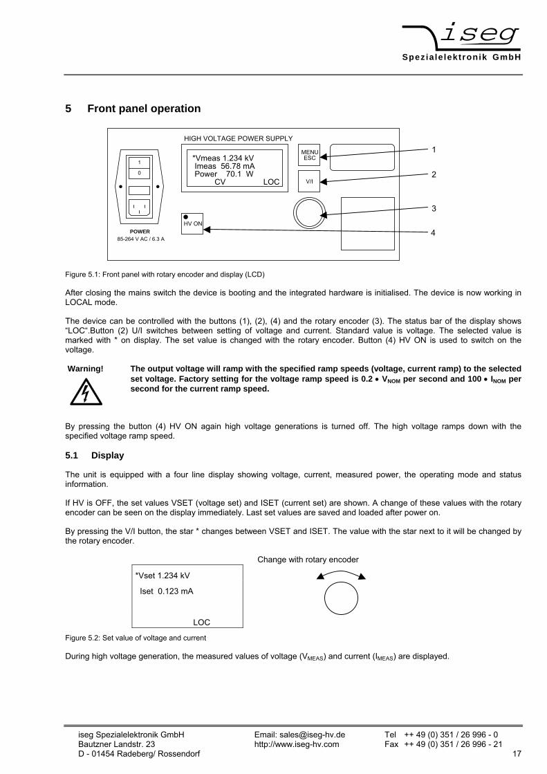
5 Front panel operation
V/I
MENUESC
HV ON
*Vmeas 1.234 kV Imeas 56.78 mA Power 70.1 W CV LOC
HIGH VOLTAGE POWER SUPPLY
1
0
POWER85-264 V AC / 6.3 A
Figure 5.1: Front panel with rotary encoder and display (LCD)
After closing the mains switch the device is booting and the integrated hardware is initialised. The device is now working in LOCAL mode.
The device can be controlled with the buttons (1), (2), (4) and the rotary encoder (3). The status bar of the display shows “LOC“.Button (2) U/I switches between setting of voltage and current. Standard value is voltage. The selected value is marked with * on display. The set value is changed with the rotary encoder. Button (4) HV ON is used to switch on the voltage.
Warning! The output voltage will ramp with the specified ramp speeds (voltage, current ramp) to the selected set voltage. Factory setting for the voltage ramp speed is 0.2 • VNOM per second and 100 • INOM per second for the current ramp speed.
By pressing the button (4) HV ON again high voltage generations is turned off. The high voltage ramps down with the specified voltage ramp speed.
5.1 Display
The unit is equipped with a four line display showing voltage, current, measured power, the operating mode and status information.
If HV is OFF, the set values VSET (voltage set) and ISET (current set) are shown. A change of these values with the rotary encoder can be seen on the display immediately. Last set values are saved and loaded after power on.
By pressing the V/I button, the star * changes between VSET and ISET. The value with the star next to it will be changed by the rotary encoder.
Change with rotary encoder
*Vset 1.234 kV
Iset 0.123 mA
LOC
Figure 5.2: Set value of voltage and current
During high voltage generation, the measured values of voltage (VMEAS) and current (IMEAS) are displayed.
1
2
3
4

Speziale lektronik GmbH
iseg Spezialelektronik GmbH Email: [email protected] Tel ++ 49 (0)351 / 26 996 - 0 Bautzner Landstr. 23 http://www.iseg-hv.com Fax ++ 49 (0)351 / 26 996 - 21 18 D - 01454 Radeberg/ Rossendorf
Change with rotary encoder
*Vmeas 1.234 kV
Imeas 0.123 mA
CV LOC
Figure 5.3: Display during high voltage generation
With a push on the rotary encoder the display switches to the set values for four seconds. If nothing is changed, the display switches to the measurement values again. It also switches back if the rotary encoder is pushed again.
If high voltage is turned off, the display shows measurement values as long as the ramping down is not finished. Four seconds after the ramp down is finished the display switches to the set values again.
5.2 Menu setting
Menu is chosen with the button Menu/ESC on front panel. Menu items are changed with the rotary encoder. The chosen item is indicated with angle brackets (e.g. >Device settings<). With a push on the rotary encoder a menu item is chosen or a set value is accepted. Every level of the menu can be left with the button MENU/ESC. If MENU/ESC is pushed in main menu, the menu will be closed.
Change with rotary encoder
>Set points <
Device settings
Device data
menu
Enter selected menu by pushing the rotary encoder
Figure 5.4: Visualization of the main menu
5.3 Menu structure
Main menu Table 5.1: Main menu
Set points Change of set values Device settings Change the unit preferences ARC-Management Change the ARC preferences Device data Display of unit data Error List Reserved for future use
By pressing the rotary encoder the selected submenu will be called.
Table 5.2: Submenu “Set points“
Vset 0.250 kV Reserved for future use Iset 100.0 mA Reserved for future use Vlim 4.000 kV Change the voltage limit Ilim 200.0 mA Change the current limit Vramp 0.800 kV/s Change the voltage ramp speed Iramp 200.0 mA/s Change the current ramp speed Kill disable Set the Kill-function enable/disable Password Not implemented yet
Speziale lektronik GmbH
iseg Spezialelektronik GmbH Email: [email protected] Tel ++ 49 (0) 351 / 26 996 - 0 Bautzner Landstr. 23 http://www.iseg-hv.com Fax ++ 49 (0) 351 / 26 996 - 21 D - 01454 Radeberg/ Rossendorf 19
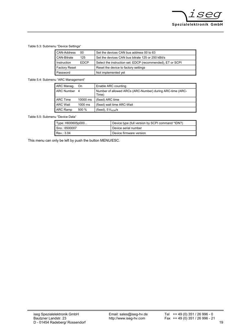
Table 5.3: Submenu “Device Settings“
CAN-Address 00 Set the devices CAN bus address 00 to 63 CAN-Bitrate 125 Set the devices CAN bus bitrate 125 or 250 kBit/s Instruction EDCP Select the instruction set: EDCP (recommended), ET or SCPI Factory Reset Reset the device to factory settings Password Not implemented yet
Table 5.4: Submenu “ARC Management“
ARC Manag. On Enable ARC counting ARC Number 4 Number of allowed ARCs (ARC-Number) during ARC-time (ARC-
Time) ARC Time 10000 ms (fixed) ARC time ARC Wait 1000 ms (fixed) wait time ARC-Wait ARC Ramp 500 % (fixed), 5.VNOM/s
Table 5.5: Submenu “Device Data“
Type: H600605p000... Device type (full version by SCPI command *IDN?) Sno.: 6500007 Device serial number Rev.: 3.04 Device firmware version
This menu can only be left by push the button MENU/ESC.
Speziale lektronik GmbH
iseg Spezialelektronik GmbH Email: [email protected] Tel ++ 49 (0)351 / 26 996 - 0 Bautzner Landstr. 23 http://www.iseg-hv.com Fax ++ 49 (0)351 / 26 996 - 21 20 D - 01454 Radeberg/ Rossendorf
6 Interface control
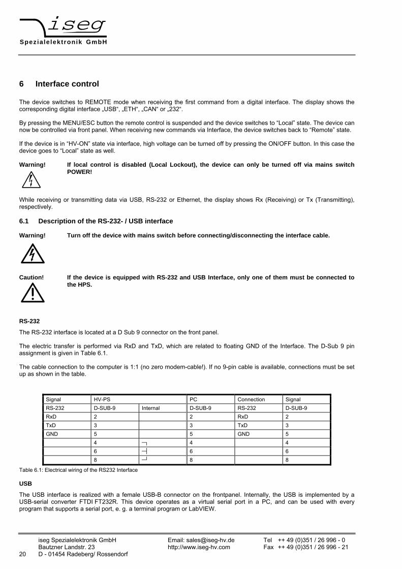
The device switches to REMOTE mode when receiving the first command from a digital interface. The display shows the corresponding digital interface „USB“, „ETH“, „CAN“ or „232“.
By pressing the MENU/ESC button the remote control is suspended and the device switches to “Local” state. The device can now be controlled via front panel. When receiving new commands via Interface, the device switches back to “Remote” state.
If the device is in “HV-ON” state via interface, high voltage can be turned off by pressing the ON/OFF button. In this case the device goes to “Local” state as well.
Warning! If local control is disabled (Local Lockout), the device can only be turned off via mains switch POWER!
While receiving or transmitting data via USB, RS-232 or Ethernet, the display shows Rx (Receiving) or Tx (Transmitting), respectively.
6.1 Description of the RS-232- / USB interface
Warning! Turn off the device with mains switch before connecting/disconnecting the interface cable.
Caution! If the device is equipped with RS-232 and USB Interface, only one of them must be connected to the HPS.
RS-232
The RS-232 interface is located at a D Sub 9 connector on the front panel.
The electric transfer is performed via RxD and TxD, which are related to floating GND of the Interface. The D-Sub 9 pin assignment is given in Table 6.1.
The cable connection to the computer is 1:1 (no zero modem-cable!). If no 9-pin cable is available, connections must be set up as shown in the table.
Signal HV-PS PC Connection Signal RS-232 D-SUB-9 Internal D-SUB-9 RS-232 D-SUB-9 RxD 2 2 RxD 2 TxD 3 3 TxD 3 GND 5 5 GND 5 4 ─┐ 4 4 6 ─┤ 6 6 8 ─┘ 8 8
Table 6.1: Electrical wiring of the RS232 Interface
USB
The USB interface is realized with a female USB-B connector on the frontpanel. Internally, the USB is implemented by a USB-serial converter FTDI FT232R. This device operates as a virtual serial port in a PC, and can be used with every program that supports a serial port, e. g. a terminal program or LabVIEW.

Speziale lektronik GmbH
iseg Spezialelektronik GmbH Email: [email protected] Tel ++ 49 (0) 351 / 26 996 - 0 Bautzner Landstr. 23 http://www.iseg-hv.com Fax ++ 49 (0) 351 / 26 996 - 21 D - 01454 Radeberg/ Rossendorf 21
Programming
The following description applies to both, RS-232 and USB interface.
The (virtual) serial interface is set to 9600 Bit/s, 8 Bit/character, no parity, 1 Stop-Bit.
The data transfer is character oriented, while the synchronization in the direction "Computer to HV PS unit” (Input direction) is established by echoes. The transfer direction “HV-PS to computer“ (Output direction) is free running.
The command transfer uses ASCII characters. Commands are terminated by <CR><LF> ($0D $0A or 13 10).
A new command may be sent immediately after the last answer was completely received (including <CR><LF>). For commands that don't return an answer, the simplest thing is to add *OPC? in EDCP instruction set:
Table 6.2: Programming seriell interface
Befehl (mit Echo) :VOLT 500;:VOLT ON;*OPC?<CR><LF> Antwort 1<CR><LF>
6.2 Description of the CAN interface
Warning! Turn off the device with mains switch before connecting/disconnecting the interface cable.
The connector for the CAN interface (male D-SUB-9) is located at the front panel and has the following pinout:
Table 6.3: Pinout CAN interface
PIN Signal
2 CAN_L (CAN Low)
3 CAN_GND
5 CAN_Shield
7 CAN_H (CAN High)
The CAN interface can be operated at the bitrates 125 or 250 kBit/s. All devices in a CAN network must be configured to the same bitrate. Furthermore, each device must be configured to a unique address in the range 0...63.
The device supports the iseg EDCP CAN command set, which is fully described in the manual
edcp_multi_channel_can.pdf.
The following software solutions for CAN control exists:
• iseg CAN Control
• iseg OPC Server
• iseg HAL (iseg Hardware Abstraction Layer)

Speziale lektronik GmbH
iseg Spezialelektronik GmbH Email: [email protected] Tel ++ 49 (0)351 / 26 996 - 0 Bautzner Landstr. 23 http://www.iseg-hv.com Fax ++ 49 (0)351 / 26 996 - 21 22 D - 01454 Radeberg/ Rossendorf
6.3 Description of the Ethernet interface
Warning! Turn off the device with mains switch before connecting/disconnecting the interface cable.
The 100 MBit/s, full duplex Ethernet interface is connected via a RJ-45 socket at the front panel.
The device can be connected to a switch with a patch cable. If it shall be connected to a PC directly, a crossover cable has to be used. The configuration of the Ethernet interface is done with a web browser or the tools of Lantronix company:
http://www.lantronix.com/support/downloads/?p=XPORT.
Please change only the settings on the network page!
Figure 6.1: Ethernet configuration
Figure 6.2: Lantronix configuration program

Speziale lektronik GmbH
iseg Spezialelektronik GmbH Email: [email protected] Tel ++ 49 (0) 351 / 26 996 - 0 Bautzner Landstr. 23 http://www.iseg-hv.com Fax ++ 49 (0) 351 / 26 996 - 21 D - 01454 Radeberg/ Rossendorf 23
Factory Ethernet settings are shown in the following table:
Table 6.4: Factory Ethernet settings
IP-address 192.168.16.221 Net mask 255.255.255.0 Default Gateway 192.168.16.1 Command port 10001 (fixed)
The connection can be tested with the ping command (Start programs accessories command).
C:\>ping 192.168.16.221 Ping will done for 192.168.16.221 with 32 bytes data: Answer from 192.168.16.221: bytes=32 time=4ms TTL=128 Answer from 192.168.16.221: bytes=32 time=4ms TTL=128 Answer from 192.168.16.221: bytes=32 time=4ms TTL=128 Answer from 192.168.16.221: bytes=32 time=4ms TTL=128 Ping statistic for 192.168.16.221 : Package: sent = 4, received = 4, lost = 0 Time in millisecond: minimum = 1ms, maximum = 4ms, average = 1ms
During communication, the HV unit act as a server, the control PC acts as a client. The following table shows the principle sequence of communication between PC and HV unit.
Table 6.5: Principle sequence of communication between PC and HV unit
Step Function call Computer HV unit HV unit Computer 1 connect() SYN 2 SYN, ACK 3 ACK 4 send() “*IDN?\r\n” 5 recv() “iseg Spezialelektronik GmbH[…]\r\n” 6 closesocket() FIN, ACK 7 FIN, ACK 8 ACK
The first three packages establish a TCP-Connection between Computer and HV unit (three way handshake). Fourth step is the inquiry from PC to HV unit. The command is ASCII coded in data field of the TCP packet. The answer is also ASCII coded send to the PC in step 5. Package No. 6 confirms the receipt of the packet and sends a FIN for termination of connection. Step 7 and 8 are the confirmation of termination of connection from HV unit and PC.
The communication can be monitored with a network sniffer (e. g. Wireshark). Control is done with the instruction sets described later. The preferred command set for Ethernet is “SCPI with EDCP”, as you can build longer Frames which reduces Ethernet Overhead.
Programming
A simple programming example (without error handling) for communication with the HV device over Ethernet is provided. This program was compiled and tested with Microsoft Visual C++ 6.0 on Windows XP.

Speziale lektronik GmbH
iseg Spezialelektronik GmbH Email: [email protected] Tel ++ 49 (0)351 / 26 996 - 0 Bautzner Landstr. 23 http://www.iseg-hv.com Fax ++ 49 (0)351 / 26 996 - 21 24 D - 01454 Radeberg/ Rossendorf
#include <stdio.h> #include <winsock.h>
int main(int argc, char *argv[])
{ WSADATA wsadata; SOCKET sock; SOCKADDR_IN sockaddr_in; int retcode; char cmd[255] = "*IDN?\r\n"; char ans[255] = ""; char buf[255]; char *crlf;
// init sockets (Berkeley style, UNIX compatible) WSAStartup(2, &wsadata);
// create TCP socket sock = socket(AF_INET, SOCK_STREAM, IPPROTO_TCP);
// bind socket to dynamic local port memset(&sockaddr_in, 0, sizeof(sockaddr_in));
sockaddr_in.sin_family = AF_INET; // UDP, TCP sockaddr_in.sin_port = htons(10001); // remote Port sockaddr_in.sin_addr.S_un.S_un_b.s_b1 = 192; // IP address sockaddr_in.sin_addr.S_un.S_un_b.s_b2 = 168; sockaddr_in.sin_addr.S_un.S_un_b.s_b3 = 16; sockaddr_in.sin_addr.S_un.S_un_b.s_b4 = 221;
// connect to server (three way handshake) connect(sock, (SOCKADDR *)&sockaddr_in, sizeof(SOCKADDR_IN));
// send command to server send(sock, cmd, strlen(cmd), 0);
// read answer from server do { retcode = recv(sock, buf, sizeof(ans), 0); If (retcode > 0) { buf[retcode] = 0; strcat(ans, buf); } crlf = strstr(ans, "\r\n"); } while ( (retcode > 0) && (crlf == 0) );
if (crlf > 0) { *crlf = 0; }
// close socket (three way handshake) and clean up closesocket(sock); WSACleanup(); printf("%s\n", ans); getchar(); return 0; }

Speziale lektronik GmbH
iseg Spezialelektronik GmbH Email: [email protected] Tel ++ 49 (0) 351 / 26 996 - 0 Bautzner Landstr. 23 http://www.iseg-hv.com Fax ++ 49 (0) 351 / 26 996 - 21 D - 01454 Radeberg/ Rossendorf 25
7 SCPI command set with EDCP
7.1 Introduction
To use this command set, select “EDCP” in the menu or use the *INSTR command. (EDCP = Enhanced Device Communication Protocol). This command set is based on the iseg EDCP CAN Protocol with Status and Event handling. The Status and Event Status Fields are explained below the SCPI table.
By entering values (e.g. set voltage) it is not necessary to add the corresponding units. The response of the device always includes the unit.
Note! Module is the description of the complete high voltage power supply. It may consist of several high voltage-channels, devices of the series HPS/LPS only have one high voltage channel.
Table 7.1: SCPI command set with EDCP
Common Commands *IDN? Query device identification *CLS Clear all events (module and channel)
*RST Reset device to save values
(Turn HV off with ramp, VSET = 0, ISET = INOM) *LLO Query operation complete status. Answer is "1" after all preceding commands are
executed *GTL Local lockout (disable front panel buttons) *INSTR? Goto local (enable front panel buttons) *INSTR,EDCP Query current instruction set ("EDCP", "SCPI", "ET") SCPI Commands :VOLTage <Voltage>[V] Set Channel Voltage :LIMit <Voltage>[V] Set Voltage Limit :BOUnds <Voltage>[V] Set Channel Voltage Bounds { ON | OFF } Set Channel On / Off (with configured ramp speed) EMCY OFF Shut Channel Emergency Off (without ramp) 1
EMCY CLR Leave state emergency off 2
:CURRent <Current>[A] Set Channel Current :LIMit <Current>[A] Set Current Limit :BOUnds <Current>[A] Set Channel Current Bounds :EVent CLEAR Clear Channel Event Status :MASK <Word> Set Channel Event Mask :MEASure :VOLTage? Query Measured Channel Voltage (V) :CURRent? Query Measured Channel Current (A)
1, 2 By shutting down the high voltage with :VOLT EMCY OFF, the channel stays in state emergency off. To turn on the high voltage again, the state emergency off must be leaved with :VOLT EMCY CLR. Next, the ChannelEventStatus bit EventEmergencyOff has to be cleared e. g. with *CLS.
Speziale lektronik GmbH
iseg Spezialelektronik GmbH Email: [email protected] Tel ++ 49 (0)351 / 26 996 - 0 Bautzner Landstr. 23 http://www.iseg-hv.com Fax ++ 49 (0)351 / 26 996 - 21 26 D - 01454 Radeberg/ Rossendorf
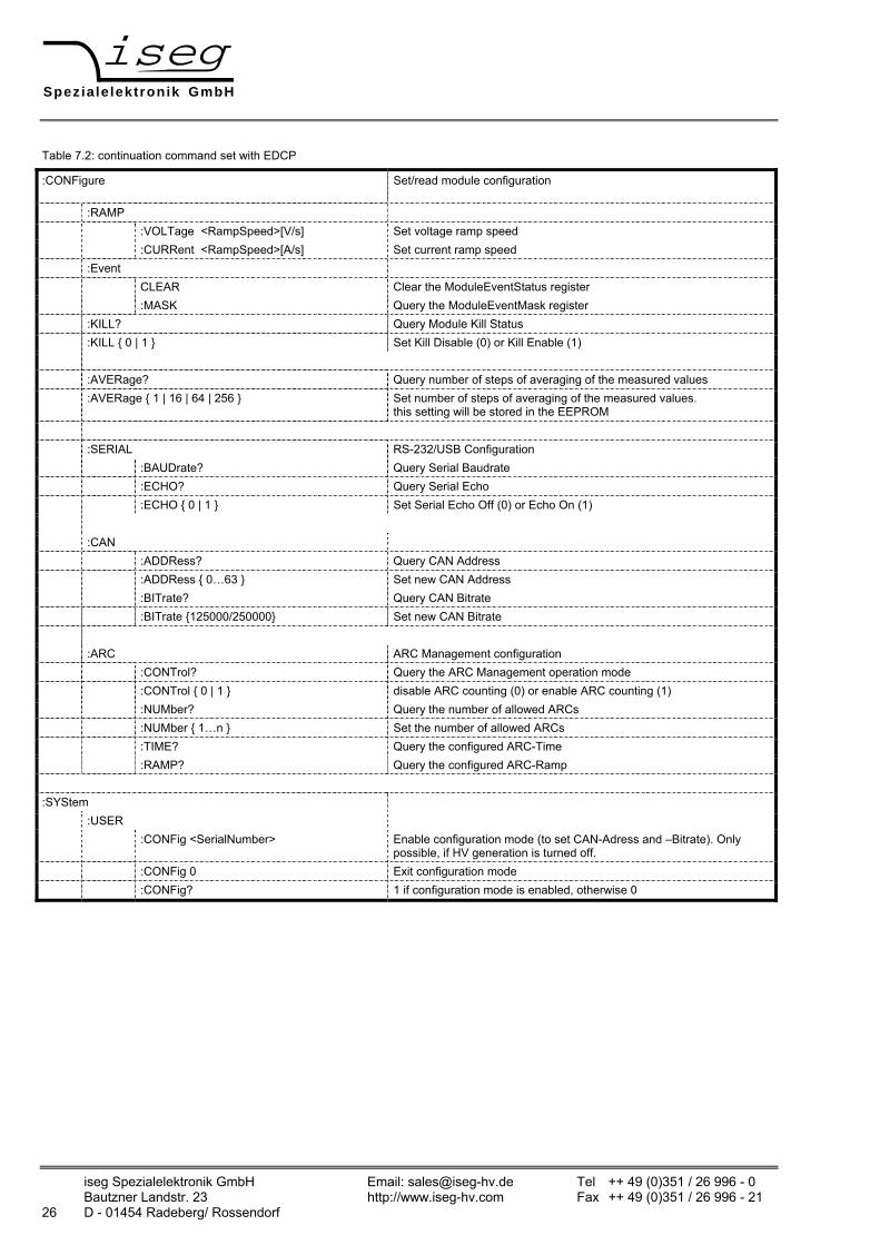
Table 7.2: continuation command set with EDCP
:CONFigure Set/read module configuration
:RAMP :VOLTage <RampSpeed>[V/s] Set voltage ramp speed :CURRent <RampSpeed>[A/s] Set current ramp speed :Event CLEAR Clear the ModuleEventStatus register :MASK Query the ModuleEventMask register :KILL? Query Module Kill Status :KILL { 0 | 1 } Set Kill Disable (0) or Kill Enable (1) :AVERage? Query number of steps of averaging of the measured values :AVERage { 1 | 16 | 64 | 256 } Set number of steps of averaging of the measured values.
this setting will be stored in the EEPROM :SERIAL RS-232/USB Configuration :BAUDrate? Query Serial Baudrate :ECHO? Query Serial Echo :ECHO { 0 | 1 } Set Serial Echo Off (0) or Echo On (1) :CAN :ADDRess? Query CAN Address :ADDRess { 0…63 } Set new CAN Address :BITrate? Query CAN Bitrate :BITrate {125000/250000} Set new CAN Bitrate :ARC ARC Management configuration :CONTrol? Query the ARC Management operation mode :CONTrol { 0 | 1 } disable ARC counting (0) or enable ARC counting (1) :NUMber? Query the number of allowed ARCs :NUMber { 1…n } Set the number of allowed ARCs :TIME? Query the configured ARC-Time :RAMP? Query the configured ARC-Ramp :SYStem :USER :CONFig <SerialNumber> Enable configuration mode (to set CAN-Adress and –Bitrate). Only
possible, if HV generation is turned off. :CONFig 0 Exit configuration mode :CONFig? 1 if configuration mode is enabled, otherwise 0
Speziale lektronik GmbH
iseg Spezialelektronik GmbH Email: [email protected] Tel ++ 49 (0) 351 / 26 996 - 0 Bautzner Landstr. 23 http://www.iseg-hv.com Fax ++ 49 (0) 351 / 26 996 - 21 D - 01454 Radeberg/ Rossendorf 27
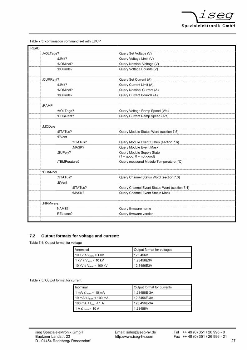
Table 7.3: continuation command set with EDCP
:READ :VOLTage? Query Set Voltage (V) :LIMit? Query Voltage Limit (V) :NOMinal? Query Nominal Voltage (V) :BOUnds? Query Voltage Bounds (V) :CURRent? Query Set Current (A) :LIMit? Query Current Limit (A) :NOMinal? Query Nominal Current (A) :BOUnds? Query Current Bounds (A) :RAMP :VOLTage? Query Voltage Ramp Speed (V/s) :CURRent? Query Current Ramp Speed (A/s) :MODule :STATus? Query Module Status Word (section 7.5) :EVent :STATus? Query Module Event Status (section 7.6) :MASK? Query Module Event Mask :SUPply? Query Module Supply State
(1 = good, 0 = not good) :TEMPerature? Query measured Module Temperature (°C) :CHANnel :STATus? Query Channel Status Word (section 7.3) :EVent :STATus? Query Channel Event Status Word (section 7.4) :MASK? Query Channel Event Status Mask :FIRMware NAME? Query firmware name RELease? Query firmware version
7.2 Output formats for voltage and current: Table 7.4: Output format for voltage
Vnominal Output format for voltages 100 V ≤ Vnom < 1 kV 123.456V 1 kV ≤ Vnom < 10 kV 1.23456E3V 10 kV ≤ Vnom < 100 kV 12.3456E3V
Table 7.5: Output format for current
Inominal Output format for currents 1 mA ≤ Inom < 10 mA 1.23456E-3A 10 mA ≤ Inom < 100 mA 12.3456E-3A 100 mA ≤ Inom < 1 A 123.456E-3A 1 A ≤ Inom < 10 A 1.23456A
Speziale lektronik GmbH
iseg Spezialelektronik GmbH Email: [email protected] Tel ++ 49 (0)351 / 26 996 - 0 Bautzner Landstr. 23 http://www.iseg-hv.com Fax ++ 49 (0)351 / 26 996 - 21 28 D - 01454 Radeberg/ Rossendorf
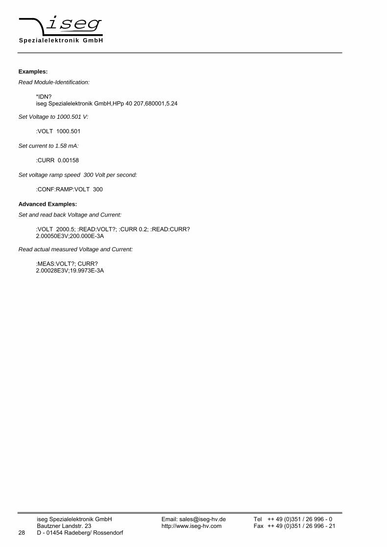
Examples:
Read Module-Identification:
*IDN? iseg Spezialelektronik GmbH,HPp 40 207,680001,5.24
Set Voltage to 1000.501 V:
:VOLT 1000.501
Set current to 1.58 mA:
:CURR 0.00158
Set voltage ramp speed 300 Volt per second:
:CONF:RAMP:VOLT 300
Advanced Examples:
Set and read back Voltage and Current:
:VOLT 2000.5; :READ:VOLT?; :CURR 0.2; :READ:CURR? 2.00050E3V;200.000E-3A
Read actual measured Voltage and Current:
:MEAS:VOLT?; CURR? 2.00028E3V;19.9973E-3A

Speziale lektronik GmbH
iseg Spezialelektronik GmbH Email: [email protected] Tel ++ 49 (0) 351 / 26 996 - 0 Bautzner Landstr. 23 http://www.iseg-hv.com Fax ++ 49 (0) 351 / 26 996 - 21 D - 01454 Radeberg/ Rossendorf 29
7.3 Channel status (read access)
:READ:CHANnel:STATus? Table 7.6: channel status register
Bit15 Bit14 Bit13 Bit12 Bit11 Bit10 Bit9 Bit8
isVoltageLimit isCurrentLimit isTrip IsExtenal -Inhibit
isVoltage-Bounds
isCurrent-Bounds
isArcError res
Bit7 Bit6 Bit5 Bit4 Bit3 Bit2 Bit1 Bit0 isConstant- Voltage
isConstant-Current
isEmergency-Off
isRamping isOn isInputError isArc res
The ChannelStatus register describes the actual status. Depending on the status of the channel the bits will be set or reset.
Table 7.7: Explanation of individual bits of the cannel status Registers
Bit Bit ist 1 Bit ist 0 isVoltageLimit Voltage limit Vmax is exceeded Voltage limit not exceeded isCurrentLimit Current limit Imax is exceeded Current limit not exceeded
isTrip High voltage has been shut down without ramp because voltage or current limit or current set has been exceeded in Kill-Enable
No Trip
isExternalInhibit External Inhibit is active No External Inhibit isVoltageBounds Voltage out of programmed bounds Voltage is within programmed bounds isCurrentBounds Current out of programmed bounds Current is within programmed bounds
isConstantVoltage Voltage control active (evaluation is guaranteed when no ramp is running)
Voltage control not active
isConstantCurrent Current control active (evaluation is guaranteed when no ramp is running)
Current control not active
isEmergencyOff Emergency off without ramp No Emergency Off
isOn High voltage is actively generated or measured voltage is above 60 Volt
High voltage is not actively generated and measured voltage is below 60 Volt
IsRamping Ramp is running No Ramp is running isInputError Input error No Input error res Reserved Reserved
Speziale lektronik GmbH
iseg Spezialelektronik GmbH Email: [email protected] Tel ++ 49 (0)351 / 26 996 - 0 Bautzner Landstr. 23 http://www.iseg-hv.com Fax ++ 49 (0)351 / 26 996 - 21 30 D - 01454 Radeberg/ Rossendorf
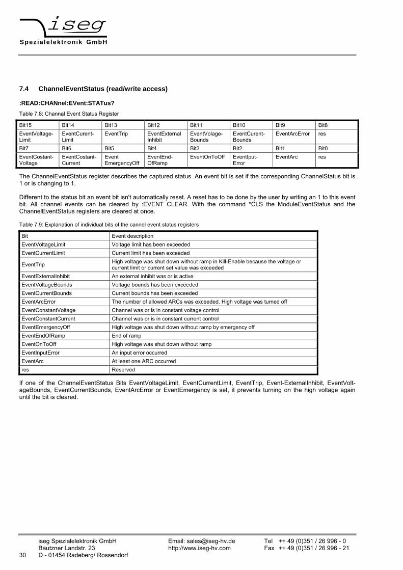
7.4 ChannelEventStatus (read/write access)
:READ:CHANnel:EVent:STATus? Table 7.8: Channal Event Status Register Bit15 Bit14 Bit13 Bit12 Bit11 Bit10 Bit9 Bit8 EventVoltage- Limit
EventCurent-Limit
EventTrip EventExternal Inhibit
EventVolage- Bounds
EventCurent- Bounds
EventArcError res
Bit7 Bit6 Bit5 Bit4 Bit3 Bit2 Bit1 Bit0 EventCostant-Voltage
EventCostant-Current
Event EmergencyOff
EventEnd- OfRamp
EventOnToOff EventIput- Error
EventArc res
The ChannelEventStatus register describes the captured status. An event bit is set if the corresponding ChannelStatus bit is 1 or is changing to 1.
Different to the status bit an event bit isn't automatically reset. A reset has to be done by the user by writing an 1 to this event bit. All channel events can be cleared by :EVENT CLEAR. With the command *CLS the ModuleEventStatus and the ChannelEventStatus registers are cleared at once.
Table 7.9: Explanation of individual bits of the cannel event status registers
Bit Event description EventVoltageLimit Voltage limit has been exceeded EventCurrentLimit Current limit has been exceeded
EventTrip High voltage was shut down without ramp in Kill-Enable because the voltage or current limit or current set value was exceeded
EventExternalInhibit An external inhibit was or is active EventVoltageBounds Voltage bounds has been exceeded EventCurrentBounds Current bounds has been exceeded EventArcError The number of allowed ARCs was exceeded. High voltage was turned off EventConstantVoltage Channel was or is in constant voltage control EventConstantCurrent Channel was or is in constant current control EventEmergencyOff High voltage was shut down without ramp by emergency off EventEndOfRamp End of ramp EventOnToOff High voltage was shut down without ramp EventInputError An input error occurred EventArc At least one ARC occurred res Reserved
If one of the ChannelEventStatus Bits EventVoltageLimit, EventCurrentLimit, EventTrip, Event-ExternalInhibit, EventVolt-ageBounds, EventCurrentBounds, EventArcError or EventEmergency is set, it prevents turning on the high voltage again until the bit is cleared.
Speziale lektronik GmbH
iseg Spezialelektronik GmbH Email: [email protected] Tel ++ 49 (0) 351 / 26 996 - 0 Bautzner Landstr. 23 http://www.iseg-hv.com Fax ++ 49 (0) 351 / 26 996 - 21 D - 01454 Radeberg/ Rossendorf 31
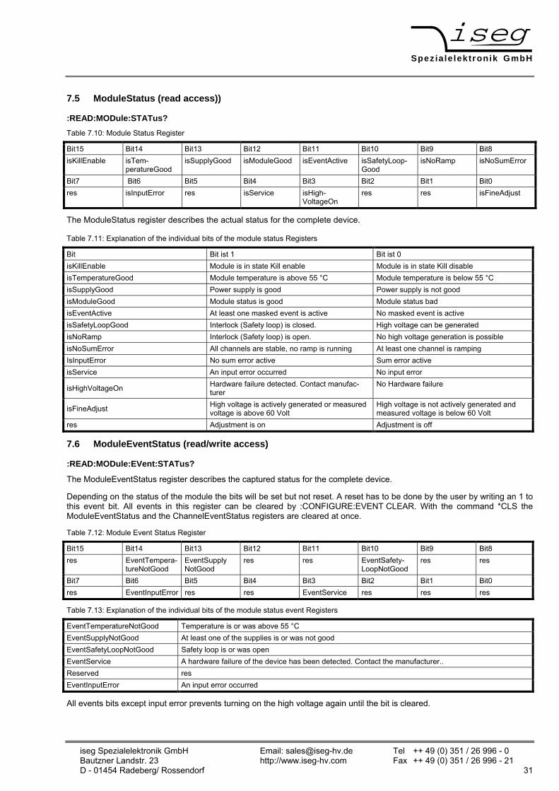
7.5 ModuleStatus (read access))
:READ:MODule:STATus? Table 7.10: Module Status Register Bit15 Bit14 Bit13 Bit12 Bit11 Bit10 Bit9 Bit8 isKillEnable isTem-
peratureGood isSupplyGood isModuleGood isEventActive isSafetyLoop-
Good isNoRamp isNoSumError
Bit7 Bit6 Bit5 Bit4 Bit3 Bit2 Bit1 Bit0 res isInputError res isService isHigh-
VoltageOn res res isFineAdjust
The ModuleStatus register describes the actual status for the complete device.
Table 7.11: Explanation of the individual bits of the module status Registers
Bit Bit ist 1 Bit ist 0 isKillEnable Module is in state Kill enable Module is in state Kill disable isTemperatureGood Module temperature is above 55 °C Module temperature is below 55 °C isSupplyGood Power supply is good Power supply is not good isModuleGood Module status is good Module status bad isEventActive At least one masked event is active No masked event is active isSafetyLoopGood Interlock (Safety loop) is closed. High voltage can be generated isNoRamp Interlock (Safety loop) is open. No high voltage generation is possible isNoSumError All channels are stable, no ramp is running At least one channel is ramping IsInputError No sum error active Sum error active isService An input error occurred No input error
isHighVoltageOn Hardware failure detected. Contact manufac-turer
No Hardware failure
isFineAdjust High voltage is actively generated or measured voltage is above 60 Volt
High voltage is not actively generated and measured voltage is below 60 Volt
res Adjustment is on Adjustment is off
7.6 ModuleEventStatus (read/write access)
:READ:MODule:EVent:STATus?
The ModuleEventStatus register describes the captured status for the complete device.
Depending on the status of the module the bits will be set but not reset. A reset has to be done by the user by writing an 1 to this event bit. All events in this register can be cleared by :CONFIGURE:EVENT CLEAR. With the command *CLS the ModuleEventStatus and the ChannelEventStatus registers are cleared at once.
Table 7.12: Module Event Status Register
Bit15 Bit14 Bit13 Bit12 Bit11 Bit10 Bit9 Bit8 res EventTempera-
tureNotGood EventSupply NotGood
res res EventSafety-LoopNotGood
res res
Bit7 Bit6 Bit5 Bit4 Bit3 Bit2 Bit1 Bit0 res EventInputError res res EventService res res res
Table 7.13: Explanation of the individual bits of the module status event Registers
EventTemperatureNotGood Temperature is or was above 55 °C EventSupplyNotGood At least one of the supplies is or was not good EventSafetyLoopNotGood Safety loop is or was open EventService A hardware failure of the device has been detected. Contact the manufacturer.. Reserved res EventInputError An input error occurred
All events bits except input error prevents turning on the high voltage again until the bit is cleared.

Speziale lektronik GmbH
iseg Spezialelektronik GmbH Email: [email protected] Tel ++ 49 (0)351 / 26 996 - 0 Bautzner Landstr. 23 http://www.iseg-hv.com Fax ++ 49 (0)351 / 26 996 - 21 32 D - 01454 Radeberg/ Rossendorf
8 Further Command Sets
Note! The device is compatible with further command sets (ET command set, SCPI command set old). More Information about this command sets can be requested from iseg Spezialelektronik GmbH. These command sets will not be updated, e.g. parameterization of the ARC management.
9 Error
9.1 Error acknowledgement
With the following options an error event can be reset or acknowledged:
• By pressing the button MENU/ESC at the front panel (section 5.1) or
• Via the digital interfaces with the command *CLS (section 7.1)
9.2 Error messages on the LC-Display Table 9.1: Error messages on the LC-Display
Error messages during operation Display: Explanation: ILK Safety loop (Interlock) is not closed. No high voltage generation possible. TEMP High voltage has been shut down because of over temperature SPLY Auxiliary voltage or DC link voltage exceeds its lower or upper threshold VLIM Voltage limit VLIM exceeded ILIM Current limit ILIM exceeded ARC Predefined number of ARCs exceeded EMCY High voltage has been shut down with Emergency Off TRIP Set current exceeded in mode Kill Enable. High voltage is shut down.
9.3 Further Errors Table 9.2: Further Errors
Unit does not provide output voltage and the fans are not working ⇒ - Check supply voltage and connection
Unit does not provide output voltage but the fans are working. ⇒
- Check supply voltage - Check environmental temperature (TU ≤ 50°C) - Check safety loop
External fuses trip during switch on. ⇒ - Use fuses with slow characteristic (inrush current 25 A)
If these instructions do not lead to a good result, this unit must be checked by an authorised agent or shipped to the factory.
10 Maintenance
For compliance of the specified accuracy of set and monitor signals, the unit has to be recalibrated once a year.
Repair and maintenance may only be performed by trained and authorized personnel.