Embed Size (px)
DESCRIPTION
ENLACES INALAMBRICOS
Citation preview
Fluidmesh 2200 Series User manual
Firmware Version 4.0
Fluidmesh 2200 Series
Copyright © 2005-2007 Fluidmesh Networks, Inc.

2
3
WARNING ONLY QUALIFIED PERSONNEL SHOULD INSTALL THIS UNIT. THE INSTALLATION SHOULD CONFORM TO ALL LOCAL CODES. IN SOME COUNTRIES, A CERTIFIED ELECTRICIAN MAY BE REQUIRED.
CAUTION When open, the apparatus should not be dripping or splashing. Objects filled with liquid should not be placed on the apparatus.
NOTICE TO USERS Copyright © Fluidmesh Networks, Inc. All rights reserved. This manual or the software described herein, in whole or in part, shall not be reproduced, translated or reduced to any machine-readable form without prior written approval from Fluidmesh Networks, Inc. FLUIDMESH NETWORKS, INC. PROVIDES NO WARRANTY WITH REGARD TO THIS MANUAL, THE SOFTWARE OR OTHER INFORMATION CONTAINED HEREIN AND HEREBY EXPRESSLY DISCLAIMS ANY IMPLIED WARRANTIES OF MERCHANTABILITY OR FITNESS FOR ANY PARTICULAR PURPOSE WITH REGARD TO THIS MANUAL, THE SOFTWARE OR SUCH OTHER INFORMATION. IN NO EVENT SHALL FLUIDMESH NETWORKS, INC. BE LIABLE FOR ANY INCIDENTAL, CONSEQUENTIAL OR SPECIAL DAMAGES, WHETHER BASED ON TORT, CONTRACT, OR OTHERWISE, ARISING OUT OF OR IN CONNECTION WITH THIS MANUAL, THE SOFTWARE OR OTHER INFORMATION CONTAINED HEREIN OR THE USE THEREOF. Fluidmesh Networks, Inc. reserves the right to make any modification to this manual or the information contained herein at any time without notice. The software described herein may also be governed by the terms of a separate user license agreement. Fluidmesh is a trademark of Fluidmesh Networks, Inc. Microsoft, Windows, Internet Explorer are registered trademarks of Microsoft Corporation in the United States and/or other countries. Ethernet is a registered trademark of Xerox Corporation. All other brands and product names are trademarks or registered trademarks of their respective owners.
4
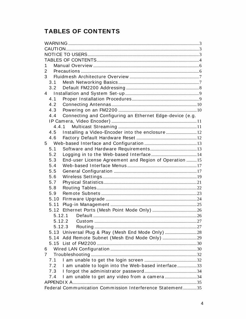
TABLES OF CONTENTS WARNING ...................................................................................................................3 CAUTION.....................................................................................................................3 NOTICE TO USERS..................................................................................................3 TABLES OF CONTENTS..........................................................................................4 1 Manual Overview .............................................................................................6 2 Precautions ........................................................................................................6 3 Fluidmesh Architecture Overview .............................................................7
3.1 Mesh Networking Basics .......................................................................7 3.2 Default FM2200 Addressing ................................................................8
4 Installation and System Set-up.................................................................9 4.1 Proper Installation Procedures ...........................................................9 4.2 Connecting Antennas ...........................................................................10 4.3 Powering on an FM2200 .....................................................................10 4.4 Connecting and Configuring an Ethernet Edge-device (e.g. IP Camera, Video Encoder) ...........................................................................11
4.4.1 Multicast Streaming .....................................................................11 4.5 Installing a Video-Encoder into the enclosure ...........................12 4.6 Factory Default Hardware Reset .....................................................12
5 Web-based Interface and Configuration ..............................................13 5.1 Software and Hardware Requirements.........................................13 5.2 Logging in to the Web-based Interface ........................................14 5.3 End-user License Agreement and Region of Operation .........15 5.4 Web-based Interface Menus .............................................................17 5.5 General Configuration .........................................................................17 5.6 Wireless Settings ...................................................................................19 5.7 Physical Statistics..................................................................................21 5.8 Routing Tables........................................................................................22 5.9 Remote Subnets ....................................................................................23 5.10 Firmware Upgrade ................................................................................24 5.11 Plug-in Management ............................................................................25 5.12 Ethernet Ports (Mesh Point Mode Only) .......................................26
5.12.1 Default ...........................................................................................26 5.12.2 Custom ..........................................................................................27 5.12.3 Routing ..........................................................................................27
5.13 Universal Plug & Play (Mesh End Mode Only) ............................28 5.14 Add Remote Subnet (Mesh End Mode Only) ..............................29 5.15 List of FM2200 ........................................................................................30
6 Wired LAN Configuration ............................................................................30 7 Troubleshooting .............................................................................................32
7.1 I am unable to get the login screen ..............................................32 7.2 I am unable to login into the Web-based interface .................33 7.3 I forgot the administrator password..............................................34 7.4 I am unable to get any video from a camera ............................34
APPENDIX A.............................................................................................................35 Federal Communication Commission Interference Statement............35

5
FCC Radiation Exposure Statement ...........................................................35 Industry Canada ....................................................................................................35 EC Declaration of Conformity ...........................................................................35 APPENDIX B.............................................................................................................37 Contact Information .............................................................................................37

6
1 Manual Overview This manual explains how to install and operate a Fluidmesh 2200 unit. Note that the screenshots shown in this manual are explanatory examples and may be different from the ones that appear when you run the configuration software.
2 Precautions This product is for professional use only. This product has been designed with safety in mind. However, if not used properly, it can cause fires which may lead to serious bodily injuries. To avoid such accidents, make sure that you are properly qualified to install this product. In Case of Breakdown In case of system breakdown, discontinue use and immediately contact your authorized Fluidmesh Networks dealer or Fluidmesh Networks, Inc. directly. In Case of Abnormal Operations If the unit emits smoke or an unusual smell, if water or other foreign matter enters the enclosure, or if your drop the unit or damage the enclosure, power off the unit immediately and contact your authorized Fluidmesh Networks dealer or Fluidmesh Networks, Inc. directly.

7
3 Fluidmesh Architecture Overview This section describes the Fluidmesh mesh networking architecture and the basic functions of the Fluidmesh 2200 (FM2200) unit.
3.1 Mesh Networking Basics Fluidmesh Networks develops wireless networking solutions based on innovative mesh networking architecture which presents unmatched advantages in terms of reliability and flexibility compared to any traditional wireless solution. Using Fluidmesh technology for your network allows you to take advantage of this powerful wireless mesh networking architecture. A sample Wireless Mesh Network (WMN) is shown in Fig. 1. In a wireless mesh network, every FM2200 unit transmits the data packets coming from the devices directly attached to it and also acts as an “intelligent router” able to forward packets coming from other FM2200 units through the optimal path. In a redundant and reliable mesh network, every stream of data packets has multiple available paths to reach the base station and the network forwards the packets through the optimal path at any point in time. The absence of any single point of failure incredibly increases its reliability compared to any other transmission technology, either wireless or wired.
Figure 1. Fluidmesh mesh networking architecture.
8
The FM2200 has two modes of operation:
Mesh point mode Mesh end mode
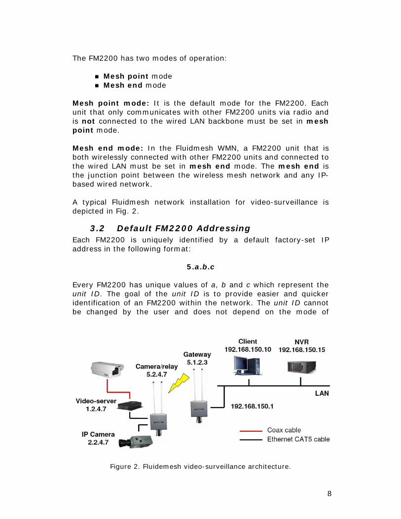
Mesh point mode: It is the default mode for the FM2200. Each unit that only communicates with other FM2200 units via radio and is not connected to the wired LAN backbone must be set in mesh point mode. Mesh end mode: In the Fluidmesh WMN, a FM2200 unit that is both wirelessly connected with other FM2200 units and connected to the wired LAN must be set in mesh end mode. The mesh end is the junction point between the wireless mesh network and any IP-based wired network. A typical Fluidmesh network installation for video-surveillance is depicted in Fig. 2.
3.2 Default FM2200 Addressing Each FM2200 is uniquely identified by a default factory-set IP address in the following format:
5.a.b.c Every FM2200 has unique values of a, b and c which represent the unit ID. The goal of the unit ID is to provide easier and quicker identification of an FM2200 within the network. The unit ID cannot be changed by the user and does not depend on the mode of
Figure 2. Fluidemesh video-surveillance architecture.
9
operation, i.e., it remains unchanged both in mesh point and in mesh end mode. Each FM2200 has two Ethernet ports with a dedicated IP address. The Ethernet IP addresses depend on whether the router is operating in mesh point or mesh end mode. A detailed description of the configuration process of these operating modes can be found in Section 4. Note that the unit ID is very important as it can be exploited to quickly configure the devices, such as cameras, which will be connected to the FM2200. Please refer to Section 4 for details.
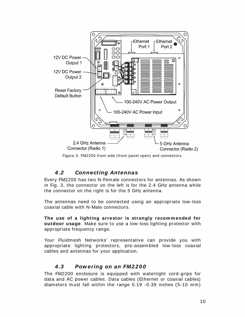
4 Installation and System Set-up The FM2200 is designed for outdoor operations. The waterproof enclosure contains a 50W power supply that is used to power the FM2200 and any other equipment installed inside the enclosure, such as one or more video-servers, Power-over-Ethernet injectors or Ethernet switches. Fig. 3 shows the connectors present on the front side of the FM2200 when the cover is removed.
4.1 Proper Installation Procedures The FM2200 can be installed on a wall or pole using the mounting adapters provided. Both wall brackets and a pole-mounting adapter are supplied with the FM2200 kit. In order to prevent overheating of the system, the FM2200 kit includes a Sunshield. Installing the Sunshield is strongly recommended in case the unit is exposed to direct solar radiation for long periods of time. IMPORTANT: Powering the FM2200 before connecting the antennas to the proper connectors (see Fig. 3) might irreparably damage the unit so always be sure to have the proper antenna attached to the FM2200 connectors.
10
4.2 Connecting Antennas Every FM2200 has two N-Female connectors for antennas. As shown in Fig. 3, the connector on the left is for the 2.4 GHz antenna while the connector on the right is for the 5 GHz antenna. The antennas need to be connected using an appropriate low-loss coaxial cable with N-Male connectors. The use of a lighting arrestor is strongly recommended for outdoor usage. Make sure to use a low-loss lighting protector with appropriate frequency range. Your Fluidmesh Networks’ representative can provide you with appropriate lighting protectors, pre-assembled low-loss coaxial cables and antennas for your application.
4.3 Powering on an FM2200 The FM2200 enclosure is equipped with watertight cord-grips for data and AC power cables. Data cables (Ethernet or coaxial cables) diameters must fall within the range 0.19 -0.39 inches (5-10 mm)
Figure 3. FM2200 front side (front panel open) and connectors.

11
while the AC power cable must be between 0.23 and 0.59 inches (6-15 mm). In order to guarantee proper sealing, make sure that all the cables connected through the watertight cord-grips have the correct diameter.
4.4 Connecting and Configuring an Ethernet Edge-device (e.g. IP Camera, Video Encoder)
The FM2200 unit has two Ethernet ports that can be used to connect Ethernet edge devices, such as IP cameras, video-encoders, DVR, VoIP phone, etc. The Ethernet edge device must be connected to the FM2200 using an Ethernet crossover cable1. By default, each Ethernet ports of the FM2200 is provided with an IP address of class A. Specifically:
IP Address Netmask Ethernet port #1 1.0.0.1 255.0.0.0 Ethernet port #2 2.0.0.1 255.0.0.0
In the default configuration, any Ethernet device connected to the FM2200 should use an IP address of class A which must be set according to the following table:
IP Address Netmask Default Gateway Camera #1 1.a.b.c 255.0.0.0 1.0.0.1 Camera #2 2.a.b.c 255.0.0.0 2.0.0.1
where ‹a, b, c› corresponds to the digits that form the unit ID of the FM2200 to which the camera is attached. The rationale behind the above configuration is to keep the Ethernet edge device configuration process as easy as possible. In fact, to make the network operational, you can simply look at the unit ID of each FM2200 and configure the related Ethernet device according to the procedure described above. No additional configuration is required. Manually setting the IP address of each FM2200 Ethernet port is possible through the Web-based Graphical User Interface (GUI) as discussed in Section 5.10.
4.4.1 Multicast Streaming
To enable multicast video-stream from IP cameras or video-encoder, no multicast group setting is required. Every multicast packet will be forwarded by the mesh point unit towards the closest mesh end unit.
1 Make sure to use a cable manufactured for outdoor usage.

12
4.5 Installing a Video-Encoder into the enclosure
One or more video-encoders can be installed directly within the enclosure. To install a video encoder, use the internal video-server mounting kit provided with the FM2200. The kit contains a movable plate that can be fixed to the enclosure. The movable plate can be placed at different heights based on the size of the video server. You can attach the video-server(s) on the moveable plate using the slots provided. The FM2200 comes with an internal 50W AC-to-DC power supply. The power supply is used both to power the FM2200 as well as other electrical equipment that might be installed inside the enclosure, such as video-servers, Power-over-Ethernet injectors or small Ethernet switches. A copy of the power supply specifications is available with the FM2200 documentation. If you want to use the internal FM2200 power supply for other equipment, make sure to understand the technical details or refer to qualified personnel to perform the operation. Note that the maximum power consumption of the FM2200 is 10 W. The sum of all electrical devices connected to the internal power supply must result in a power consumption less than 40W.
4.6 Factory Default Hardware Reset The FM2200 has a button that allows the user to reset the unit to factory default settings. The location of the button is shown in Fig. 3. To reset the FM2200 to factory default settings, power up the unit and wait approximately two minutes for the unit to boot. Once the unit is up and running, press the reset button and keep it down for 10 seconds. The LEDs will blink when the reset to factory default signal is received. Then release the button but do NOT power off the unit after the LEDs blink. The FM2200 will restore the factory default settings and automatically reboot. After the reset, the unit is restored to the mesh point mode and the administrator’s password is set to:
Username: admin Password: admin
13
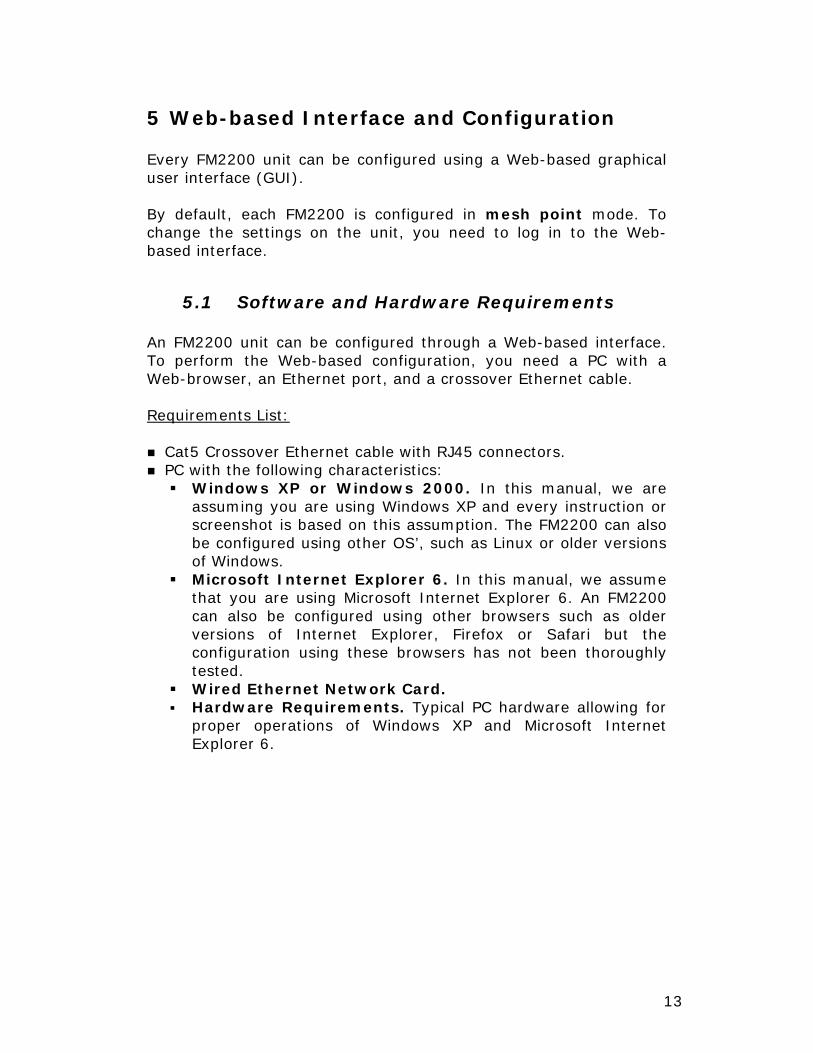
5 Web-based Interface and Configuration Every FM2200 unit can be configured using a Web-based graphical user interface (GUI). By default, each FM2200 is configured in mesh point mode. To change the settings on the unit, you need to log in to the Web-based interface.
5.1 Software and Hardware Requirements An FM2200 unit can be configured through a Web-based interface. To perform the Web-based configuration, you need a PC with a Web-browser, an Ethernet port, and a crossover Ethernet cable. Requirements List:
Cat5 Crossover Ethernet cable with RJ45 connectors. PC with the following characteristics:
Windows XP or Windows 2000. In this manual, we are assuming you are using Windows XP and every instruction or screenshot is based on this assumption. The FM2200 can also be configured using other OS’, such as Linux or older versions of Windows.
Microsoft Internet Explorer 6. In this manual, we assume that you are using Microsoft Internet Explorer 6. An FM2200
can also be configured using other browsers such as older versions of Internet Explorer, Firefox or Safari but the configuration using these browsers has not been thoroughly tested.
Wired Ethernet Network Card. Hardware Requirements. Typical PC hardware allowing for
proper operations of Windows XP and Microsoft Internet Explorer 6.
14
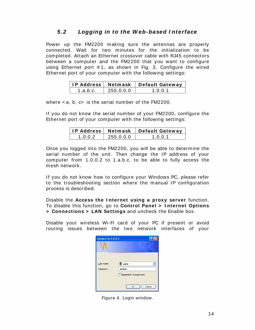
5.2 Logging in to the Web-based Interface Power up the FM2200 making sure the antennas are properly connected. Wait for two minutes for the initialization to be completed. Attach an Ethernet crossover cable with RJ45 connectors between a computer and the FM2200 that you want to configure using Ethernet port #1, as shown in Fig. 3. Configure the wired Ethernet port of your computer with the following settings:
IP Address Netmask Default Gateway 1.a.b.c. 255.0.0.0 1.0.0.1
where <a, b, c> is the serial number of the FM2200. If you do not know the serial number of your FM2200, configure the Ethernet port of your computer with the following settings:
IP Address Netmask Default Gateway 1.0.0.2 255.0.0.0 1.0.0.1
Once you logged into the FM2200, you will be able to determine the serial number of the unit. Then change the IP address of your computer from 1.0.0.2 to 1.a.b.c. to be able to fully access the mesh network. If you do not know how to configure your Windows PC, please refer to the troubleshooting section where the manual IP configuration process is described. Disable the Access the Internet using a proxy server function. To disable this function, go to Control Panel > Internet Options > Connections > LAN Settings and uncheck the Enable box. Disable your wireless Wi-Fi card of your PC if present or avoid routing issues between the two network interfaces of your
Figure 4. Login window.

15
computer. Open a Web-browser such as Internet Explorer and type the following URL:
http://1.0.0.1 Make sure not to omit the initial “http://”. Some browsers might not work without the “http://” prefix preceding the numeric address. A Log In form asking for a user name and a password should appear as shown in Fig. 4. The default settings are:
Username: admin Password: admin
To preserve the security of your system, make sure you change the default password once the entire installation is completed. In case the Log In form does not appear, please refer to the troubleshooting section.
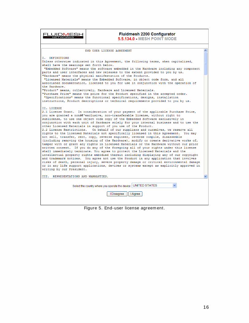
5.3 End-user License Agreement and Region of Operation
The first time you log in, you will be asked to accept the terms of the end-user license agreement and select the country where you will be operating the FM2200 unit (Fig. 5). You must accept the terms of the license agreement in order to activate the device. If you do not wish to accept the terms of the license agreement, please turn off the unit and contact Fluidmesh Networks. Choosing a wrong country/regulatory domain setting may lead to an illegal wireless configuration.
16
Figure 5. End-user license agreement.
17
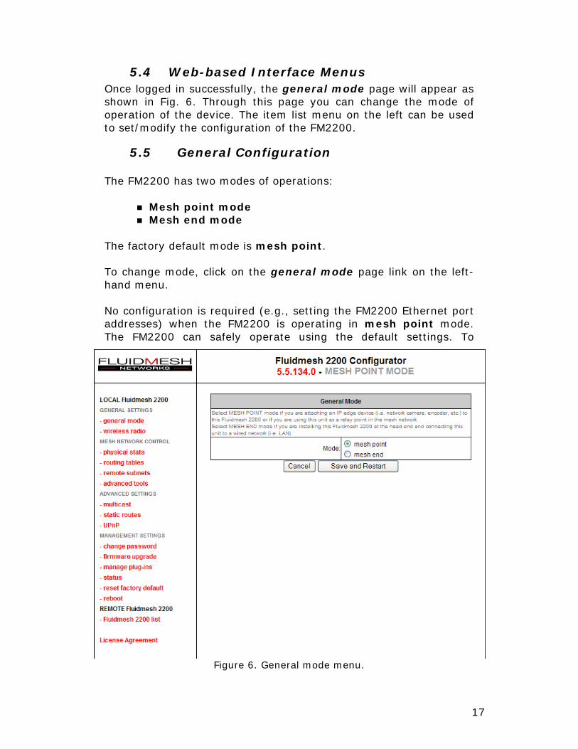
5.4 Web-based Interface Menus Once logged in successfully, the general mode page will appear as shown in Fig. 6. Through this page you can change the mode of operation of the device. The item list menu on the left can be used to set/modify the configuration of the FM2200.
5.5 General Configuration The FM2200 has two modes of operations:
Mesh point mode Mesh end mode
The factory default mode is mesh point. To change mode, click on the general mode page link on the left-hand menu. No configuration is required (e.g., setting the FM2200 Ethernet port addresses) when the FM2200 is operating in mesh point mode. The FM2200 can safely operate using the default settings. To
Figure 6. General mode menu.

18
change the default settings, access the Advanced Settings menu by clicking on the “Ethernet ports” link. Please refer to Section 5.11 for details. When operating in mesh end mode you need to configure the settings of the FM2200 Ethernet port to be connected to the control room LAN. An example is depicted in Fig. 7. Remember to use the new IP address set to configure the FM2200 unit. If you do not know how to configure the LAN settings, contact the local network administrator before changing the settings of the mesh end unit.
Figure 7. General configuration menu. Switching from mesh point mode to mesh end mode.
19
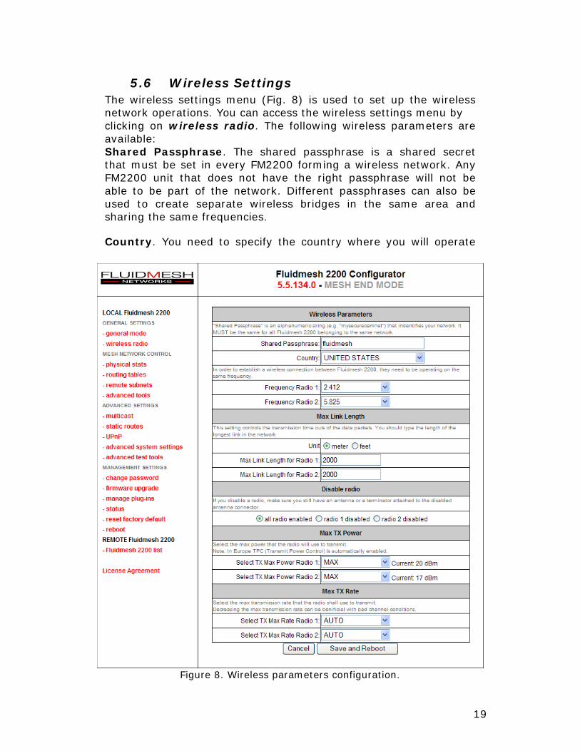
5.6 Wireless Settings The wireless settings menu (Fig. 8) is used to set up the wireless network operations. You can access the wireless settings menu by clicking on wireless radio. The following wireless parameters are available: Shared Passphrase. The shared passphrase is a shared secret that must be set in every FM2200 forming a wireless network. Any FM2200 unit that does not have the right passphrase will not be able to be part of the network. Different passphrases can also be used to create separate wireless bridges in the same area and sharing the same frequencies. Country. You need to specify the country where you will operate
Figure 8. Wireless parameters configuration.
20
the FM2200. Different countries have different telecommunications regulations. Setting the country properly allows you to operate the FM2200 in compliance with national regulations. The available frequencies and other settings related to the RF operation will vary based on the selected country. Choosing the wrong country/regulatory domain setting may lead to an illegal operation of the FM2200. Make sure the country has been properly specified before changing the frequency of the system. Frequency Selectors. Every FM2200 is equipped with a multi-band radio capable of operating on the 2.4 GHz, 4.9 GHz, 5.3 GHz, and 5.8 GHz bands. The radio operates using 20 MHz channels. You can change the frequency band in order to minimize interference with other wireless networks operating in the same area. The frequencies listed on the Frequency Selector are the carrier frequencies. Make sure you pick non-overlapping channels if you need to operate more than one unit in the same area. Maximum Link Length. The maximum distance parameter allows you to tune the transmission time-outs based on the maximum round-trip time in the longest link. You should type the length of the longest link in the network. Disable Radios. These parameters allow you to disable a specific radio in the unit. Disabling the radio does not mean turning off the radio chip. Do not disconnect any of the two antennas to avoid damages to the radio chip. Disabling a radio might be useful to exclude a particular radio in the routing calculations. Maximum Output Power. This setting controls the output power of the radio. By decreasing the output power of a radio you can decrease the overall E.I.R.P. By default, the radio transmission power is set to the maximum available. Note that the maximum transmission power may vary depending on the operating frequency channel of the radio. Transmission Rate Selection. Each FM2200 implements a proprietary optimal rate selection algorithm which is able to adapt to the specific radio channel conditions. However, through this setting, it is possible to force the rate selection algorithm to use a rate which is smaller than or equal to the maximum value specified. This option might be useful with unstable channel conditions.
21
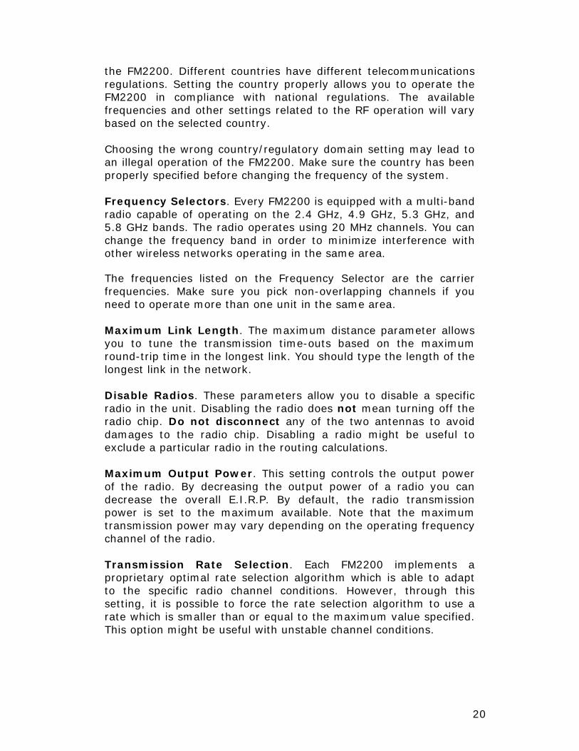
5.7 Physical Statistics The Physical Statistics page (Fig. 9) allows you to check important statistics related to the link level performance and the strength of the received signals. Signal Strength (percentage). This number provides the value of the signal strength detected during the reception of the last packet. Please notice that, on an FM2200, signal strength above 90% is excellent, 80% is good, 70% is fair, and below 60% is weak. Average Signal Strength (percentage). This number provides the average value of the signal strength detected at packet reception. Signal Strength (dBm). This number provides the value of the signal strength detected during the reception of the last packet received, in dBm, assuming the noise floor at -95 dBm. Average Signal Strength (dBm). This number provides the
Figure 9. Physical links statistics.
22
average value of the signal strength detected at packet reception, in dBm, assuming the noise floor at -95 dBm.
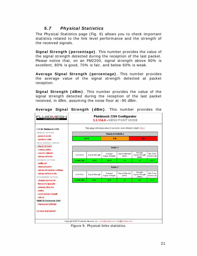
5.8 Routing Tables The routing table is automatically built by each FM2200 unit and reports the paths currently used by every packet generated/relayed by the FM2200 to reach every possible destination in the network. The best path towards a destination is selected according to the Fluidmesh routing metrics. Fig. 10 shows two different tables indicating the paths from the local FM2200 to all the available destinations and vice-versa. The “Hops” value indicates the number of FM2200 units used as relays of packets to reach the destination. If the number of hops is equal to one, there is a direct link between the local FM2200 and the destination unit. The Fluidmesh routing algorithm will select the best path towards the destination irrespective of the actual number of hops.
Figure 10. Routing tables menu.
23
Additionally, the routing tables show which radio frequency is currently used to form a link. Different colors are associated to different radio frequencies or link type as shown in the following table:
Arrow color Radio frequency/Link type RED 2.4 GHz GREY 5 GHz BLACK Wired
The routing table page can be exploited for network planning and troubleshooting.
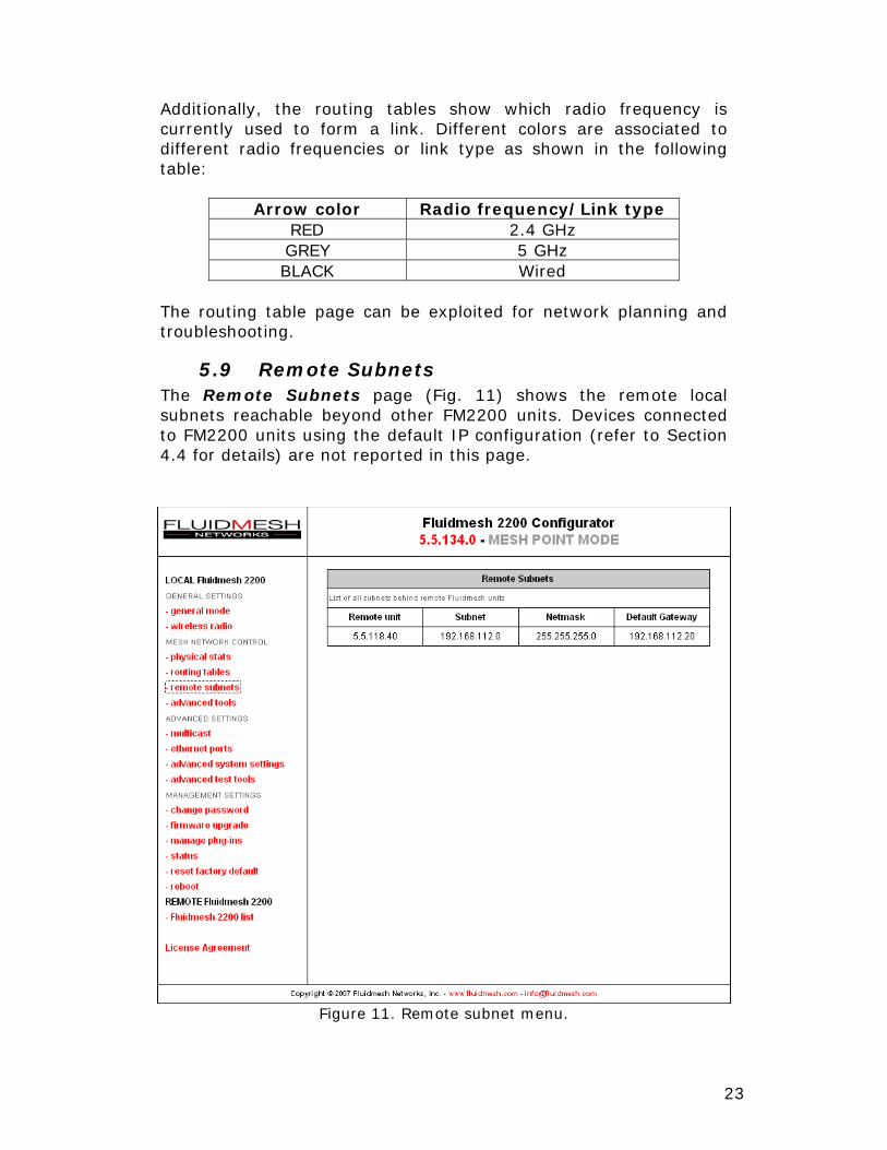
5.9 Remote Subnets The Remote Subnets page (Fig. 11) shows the remote local subnets reachable beyond other FM2200 units. Devices connected to FM2200 units using the default IP configuration (refer to Section 4.4 for details) are not reported in this page.
Figure 11. Remote subnet menu.
24
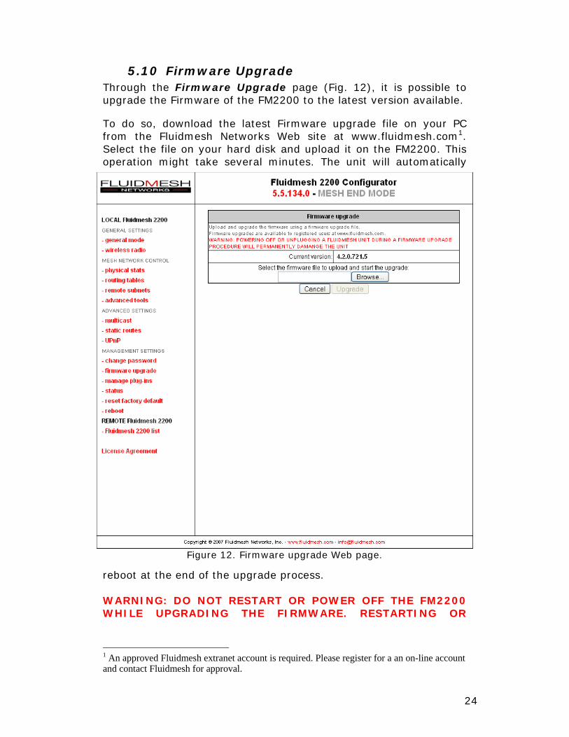
5.10 Firmware Upgrade Through the Firmware Upgrade page (Fig. 12), it is possible to upgrade the Firmware of the FM2200 to the latest version available. To do so, download the latest Firmware upgrade file on your PC from the Fluidmesh Networks Web site at www.fluidmesh.com1. Select the file on your hard disk and upload it on the FM2200. This operation might take several minutes. The unit will automatically
reboot at the end of the upgrade process. WARNING: DO NOT RESTART OR POWER OFF THE FM2200 WHILE UPGRADING THE FIRMWARE. RESTARTING OR
1 An approved Fluidmesh extranet account is required. Please register for a an on-line account and contact Fluidmesh for approval.
Figure 12. Firmware upgrade Web page.

25
POWERING OFF THE FM2200 BEFORE THE UPGRADE IS COMPLETED MIGHT DAMAGE THE UNIT. When the upgrade is completed, check the Firmware Upgrade page in order to make sure that the new Firmware version has been correctly updated. If the Firmware version has not been changed, the upgrade process has failed. Therefore, repeat the upgrading procedure from the beginning.
5.11 Plug-in Management The FM2200 supports several plug-ins which extend the common functionalities of the unit. The Plug-in page (see Fig. 13) shows the installed plug-ins and allows you to add new ones. Please contact Fluidmesh Networks for the complete list of available plug-ins.
Figure 13. Plug-ins management Web page
26
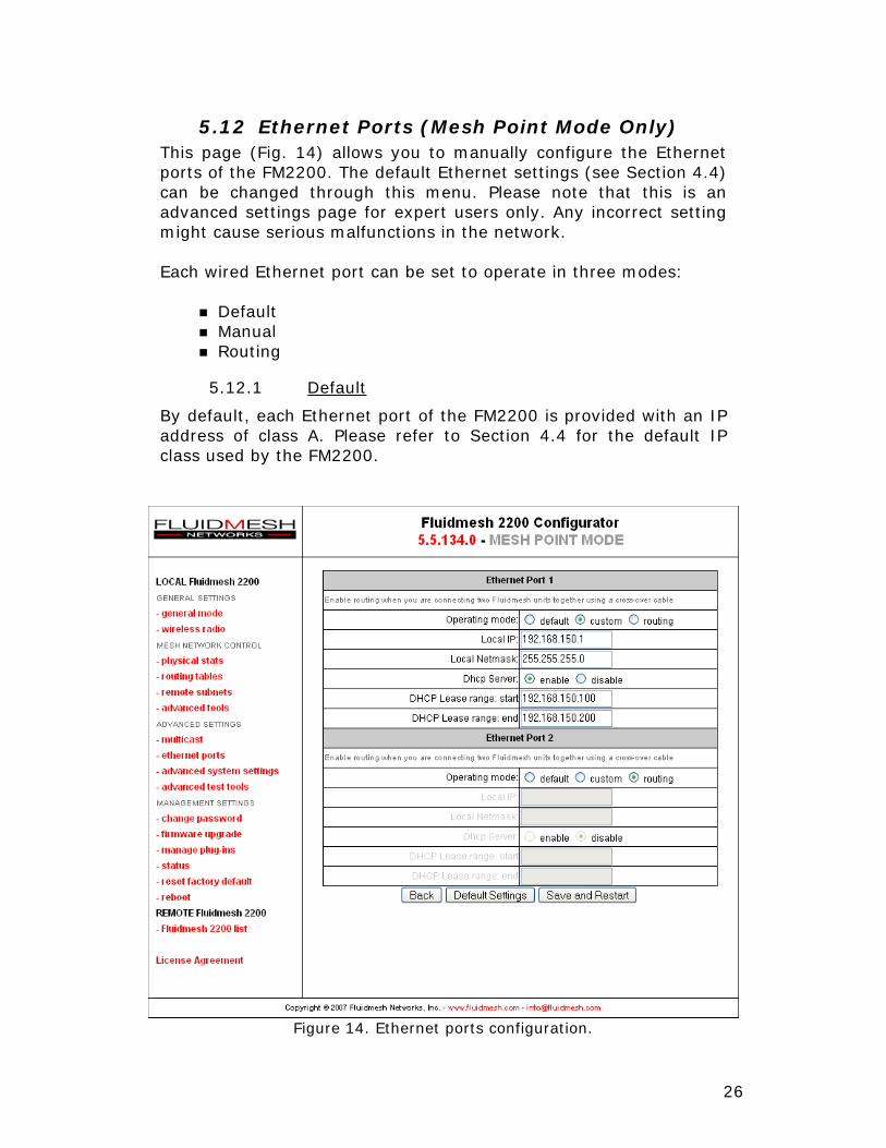
5.12 Ethernet Ports (Mesh Point Mode Only) This page (Fig. 14) allows you to manually configure the Ethernet ports of the FM2200. The default Ethernet settings (see Section 4.4) can be changed through this menu. Please note that this is an advanced settings page for expert users only. Any incorrect setting might cause serious malfunctions in the network. Each wired Ethernet port can be set to operate in three modes:
Default Manual Routing
5.12.1 Default
By default, each Ethernet port of the FM2200 is provided with an IP address of class A. Please refer to Section 4.4 for the default IP class used by the FM2200.
Figure 14. Ethernet ports configuration.
27
5.12.2 Custom
Custom settings can be provided by manually configuring the IP and netmask of every wired Ethernet port. By doing so, it is possible to create a custom VLAN behind every Fluidmesh unit. Additionally, a DHCP Server can be activated on every Ethernet port to dynamically assign IP addresses to Ethernet devices with a DHCP client enabled. Whenever possible, Fluidmesh recommends using only static IP addresses for IP cameras or video-servers/encoders.
5.12.3 Routing
The routing mode enables the Fluidmesh proprietary routing protocol to run on the Ethernet port. This configuration is required whenever multiple FM2200 units are connected to each other using crossover Ethernet cables. The routing mode must be activated on both Fluidmesh units.
28
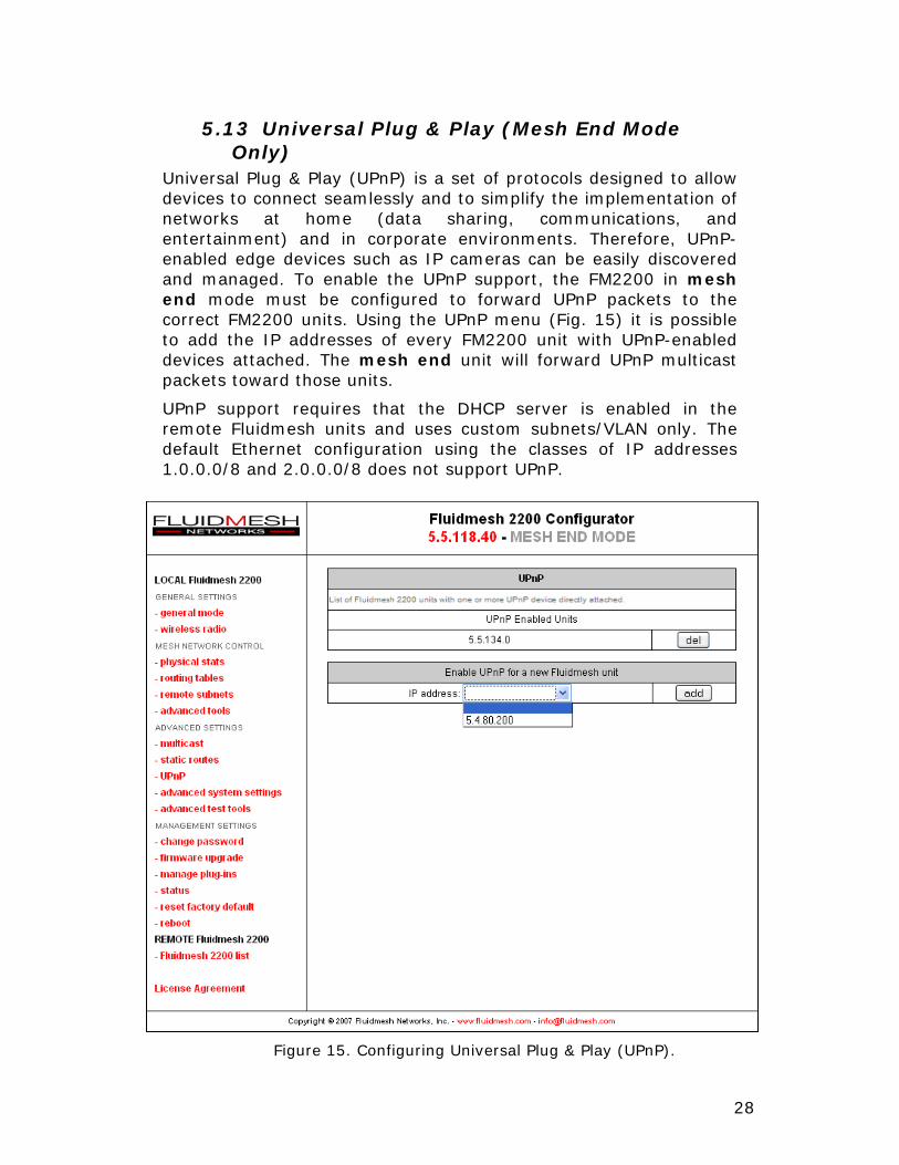
5.13 Universal Plug & Play (Mesh End Mode Only)
Universal Plug & Play (UPnP) is a set of protocols designed to allow devices to connect seamlessly and to simplify the implementation of networks at home (data sharing, communications, and entertainment) and in corporate environments. Therefore, UPnP-enabled edge devices such as IP cameras can be easily discovered and managed. To enable the UPnP support, the FM2200 in mesh end mode must be configured to forward UPnP packets to the correct FM2200 units. Using the UPnP menu (Fig. 15) it is possible to add the IP addresses of every FM2200 unit with UPnP-enabled devices attached. The mesh end unit will forward UPnP multicast packets toward those units.
UPnP support requires that the DHCP server is enabled in the remote Fluidmesh units and uses custom subnets/VLAN only. The default Ethernet configuration using the classes of IP addresses 1.0.0.0/8 and 2.0.0.0/8 does not support UPnP.
Figure 15. Configuring Universal Plug & Play (UPnP).
29
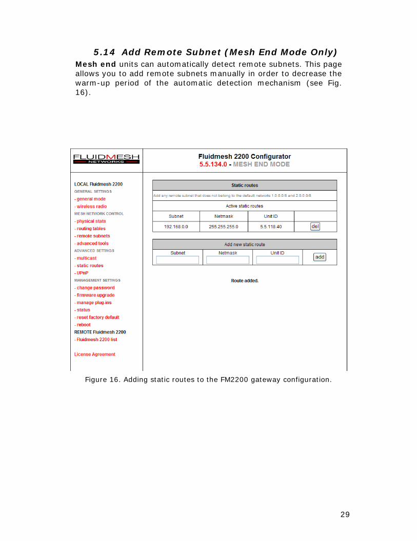
5.14 Add Remote Subnet (Mesh End Mode Only) Mesh end units can automatically detect remote subnets. This page allows you to add remote subnets manually in order to decrease the warm-up period of the automatic detection mechanism (see Fig. 16).
Figure 16. Adding static routes to the FM2200 gateway configuration.
30
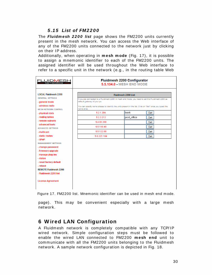
5.15 List of FM2200 The Fluidmesh 2200 list page shows the FM2200 units currently present in the mesh network. You can access the Web interface of any of the FM2200 units connected to the network just by clicking on their IP address. Additionally, when operating in mesh mode (Fig. 17), it is possible to assign a mnemonic identifier to each of the FM2200 units. The assigned identifier will be used throughout the Web interface to refer to a specific unit in the network (e.g., in the routing table Web
page). This may be convenient especially with a large mesh network.
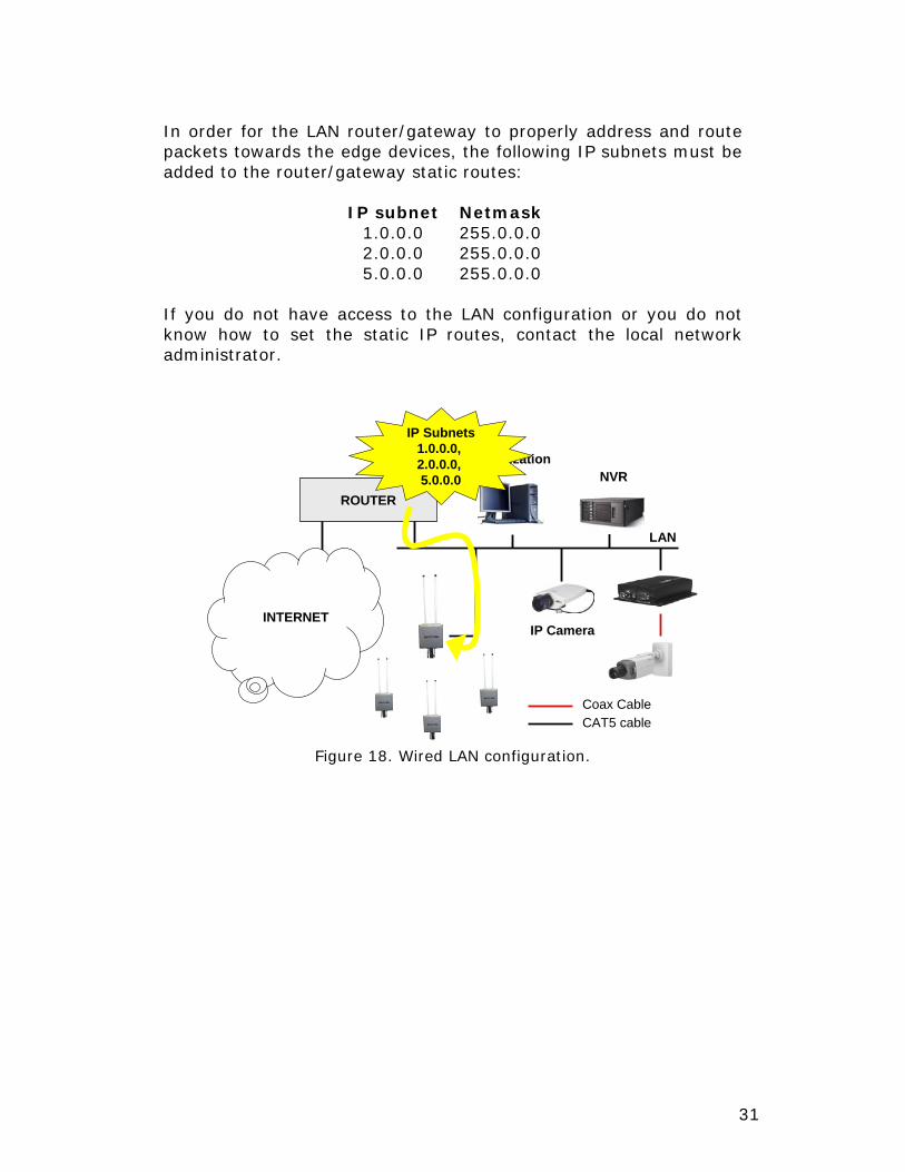
6 Wired LAN Configuration A Fluidmesh network is completely compatible with any TCP/IP wired network. Simple configuration steps must be followed to enable the wired LAN connected to FM2200 mesh end unit to communicate with all the FM2200 units belonging to the Fluidmesh network. A sample network configuration is depicted in Fig. 18.
Figure 17. FM2200 list. Mnemonic identifier can be used in mesh end mode.
31
In order for the LAN router/gateway to properly address and route packets towards the edge devices, the following IP subnets must be added to the router/gateway static routes:
IP subnet Netmask 1.0.0.0 255.0.0.0 2.0.0.0 255.0.0.0 5.0.0.0 255.0.0.0
If you do not have access to the LAN configuration or you do not know how to set the static IP routes, contact the local network administrator.
LAN
NVRVisualization
Coax CableCAT5 cable
IP Camera
ROUTER
INTERNET
IP Subnets1.0.0.0, 2.0.0.0, 5.0.0.0
Figure 18. Wired LAN configuration.
32
7 Troubleshooting The troubleshooting section will allow you to solve the most common problems encountered configuring and installing a FM2200.
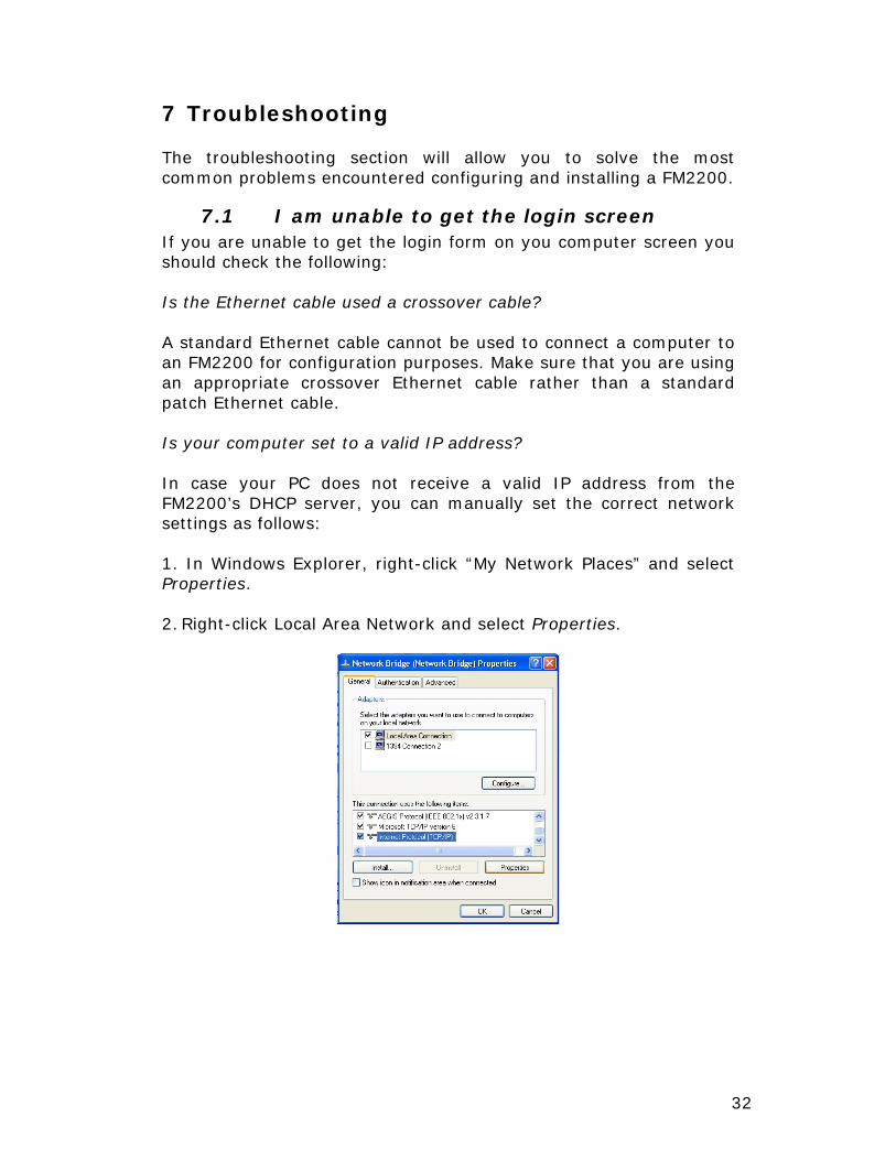
7.1 I am unable to get the login screen If you are unable to get the login form on you computer screen you should check the following: Is the Ethernet cable used a crossover cable? A standard Ethernet cable cannot be used to connect a computer to an FM2200 for configuration purposes. Make sure that you are using an appropriate crossover Ethernet cable rather than a standard patch Ethernet cable. Is your computer set to a valid IP address? In case your PC does not receive a valid IP address from the FM2200’s DHCP server, you can manually set the correct network settings as follows: 1. In Windows Explorer, right-click “My Network Places” and select Properties. 2. Right-click Local Area Network and select Properties.
33
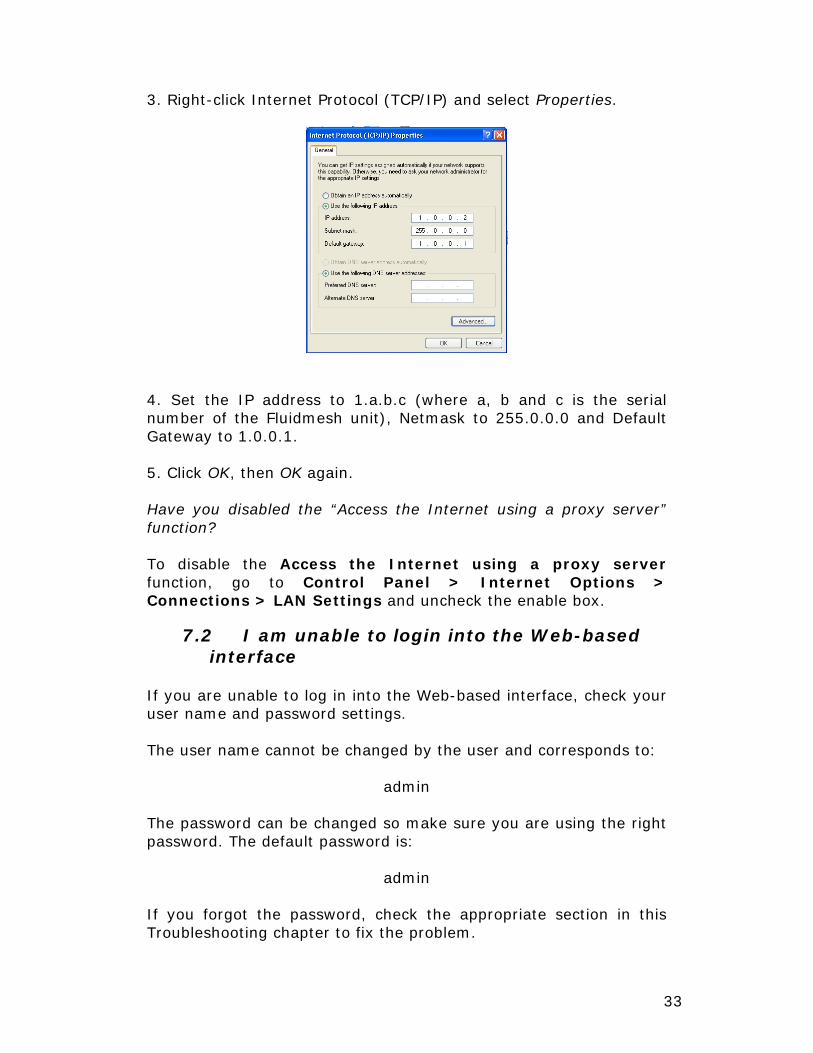
3. Right-click Internet Protocol (TCP/IP) and select Properties.
4. Set the IP address to 1.a.b.c (where a, b and c is the serial number of the Fluidmesh unit), Netmask to 255.0.0.0 and Default Gateway to 1.0.0.1. 5. Click OK, then OK again. Have you disabled the “Access the Internet using a proxy server” function? To disable the Access the Internet using a proxy server function, go to Control Panel > Internet Options > Connections > LAN Settings and uncheck the enable box.
7.2 I am unable to login into the Web-based interface
If you are unable to log in into the Web-based interface, check your user name and password settings. The user name cannot be changed by the user and corresponds to:
admin The password can be changed so make sure you are using the right password. The default password is:
admin If you forgot the password, check the appropriate section in this Troubleshooting chapter to fix the problem.
34
7.3 I forgot the administrator password If you forgot the password and need to access the Web-based interface, you must physically access the unit, open the enclosure in a weather-safe situation and reset to the factory default settings. Please refer to the instructions of Section 4.6.
7.4 I am unable to get any video from a camera
Is the Ethernet cable which connects the camera or the video server to the FM2200 a crossover cable? A standard Ethernet cable cannot be used to connect a camera or a video server to an FM2200. Make sure that you are using an appropriate crossover Ethernet cable rather than a standard patch Ethernet cable. Is the local network properly set-up to forward packets for the IP classes 5.0.0.0/8, 1.0.0.0/8 and 2.0.0.0/8 to the mesh end unit? The LAN to which the FM2200 mesh end and the recording server (NVR or DVR) are connected needs to be configured so that every packet for the class 5.0.0.0/8, 1.0.0.0/8, and 2.0.0.0/8 can be forwarded to the Fluidmesh mesh end unit. Please refer to Section 6 for details. Is the mesh point FM2200 IP address present in the routing table of the FM2200 mesh end? In case the Fluidmesh IP address is not present in the routing table of the mesh end unit, the Fluidmesh unit might be powered-off or out of range.
35
APPENDIX A
Federal Communication Commission Interference Statement
This equipment has been assembled with components that comply with the limits for a Class B digital device, pursuant to Part 15 of the FCC Rules. These limits are designed to provide reasonable protection against harmful interference in a residential installation. This equipment generates, uses and can radiate radio frequency energy and, if not installed and used in accordance with the instructions, may cause harmful interference to radio communications. However, there is no guarantee that interference will not occur in a particular installation. If this equipment does cause harmful interference to radio or television reception, which can be determined by turning the equipment off and on, the user is encouraged to try to correct the interference by one of the following measures: Reorient or relocate the receiving antenna. Increase the separation between the equipment and receiver. Connect the equipment into an outlet on a circuit different from that to which the receiver is connected. Consult the dealer or an experienced radio/TV technician for help. FCC Caution: To assure continued compliance, use only shielded interface cables when connecting to computer or peripheral devices. Any changes or modifications not expressly approved by the party responsible for compliance could void the user’s authority to operate this equipment. This transmitter must not be co-located or operating in conjunction with any other antenna or transmitter.
FCC Radiation Exposure Statement This equipment has been assembled using components that comply with FCC radiation exposure limits set forth for an uncontrolled environment. This equipment should be installed and operated with minimum distance 20 cm between the radiator and your body. This device has been assembled using components that comply with Part 15 of the FCC Rules. Operation is subject to the following two conditions: (1) This device may not cause harmful interference, and (2) this device must accept any interference received, including interference that may cause undesired operation.
Industry Canada
This Class B digital apparatus has been assembled using components that comply with Canadian ICES-003. Cet appareil numérique de la classe B est conforme à la norme NMB-003 du Canada. The use of this device in a system operating either partially or completely outdoors may require the user to obtain a license for the system according to the Canadian regulations.
EC Declaration of Conformity
Fluidmesh Networks, Inc declares under its sole responsibility that Fluidmesh 2200 series with the following Directives:

36
73/23/EEC The Low Voltage Directive and its amending directives 89/336/EEC The Electromagnetic Compatibility Directive and its amending directives 99/5/EC The Radio and Telecommunications Terminal Equipment
Directive and its amending directives has been designed and manufactured to the following specifications: EMC EN 61000-6-1; EN 61000-6-2;
EN 61000-6-3; EN 61000-6-4; EN 489-17
R&TTE EN 300 328-1 V. 1.3.1 EN 300 328-2 V. 1.2.1 EN 301 893-1 V. 1.2.1 EN 300 440-2 V. 1.3.1 Safety EN 60950-1:2001 Caution: This equipment is intended to be used in all EU and EFTA countries. Outdoor use may be restricted to certain frequencies and/or may require a license for operation. Contact local Authority for procedure to follow. Note: As far as the 2.4 Ghz range is concerned, combinations of power levels and antennas resulting in a radiated power level of above 100 mW equivalent isotropic radiated power (EIRP) are considered as not compliant with the above mentioned directive and are not allowed for use within the European community and countries that have adopted the European R&TTE directive 1999/5/EC. For more details on legal combinations of power levels and antennas, contact Fluidmesh Networks, Inc. Belgique Dans le cas d'une utilisation privée, à l'extérieur d'un bâtiment, au-dessus d'un espace public, aucun enregistrement n'est nécessaire pour une distance de moins de 300m. Pour une distance supérieure à 300m un enregistrement auprès de l'IBPT est requise. Pour une utilisation publique à l'extérieur de bâtiments, une licence de l'IBPT est requise. Pour les enregistrements et licences, veuillez contacter l'IBPT. France 2.4 GHz Bande : les fréquences 2457, 2462, 2467, et 2472 MHz sont complétement libres d'utilisation en France (en utilisation intérieur). Pour ce qui est des autres canaux, ils peuvent être soumis à autorisation selon le déparent. L'utilisation en extérieur est soumis à autorisation préalable et très restreint. Vous pouvez contacter l'Autorité de Régulation des Télécommunications (http://www.art-telecom.fr) pour de plus amples renseignements.

37
APPENDIX B
Contact Information Fluidmesh Networks, Inc. Ten-10 Post Office Square 8th Floor Boston, MA 02111 U.S.A. Tel. +1(617) 850-9007 Fax. +1(866) 458-1522 E-mail: [email protected] Web site: www.fluidmesh.com

38


Fluidmesh Networks, Inc.Ten-10 Post Office Square
8th Floor Boston, MA 02111
U.S.A.
Tel. +1(617) 381-4219Fax. +1(866) 458-1522
www.fluidmesh.com