Embed Size (px)
Citation preview
©Copyright Amkus Rescue Systems, Inc. 2016-2017 LAI-001 August 31, 2017 Rev01
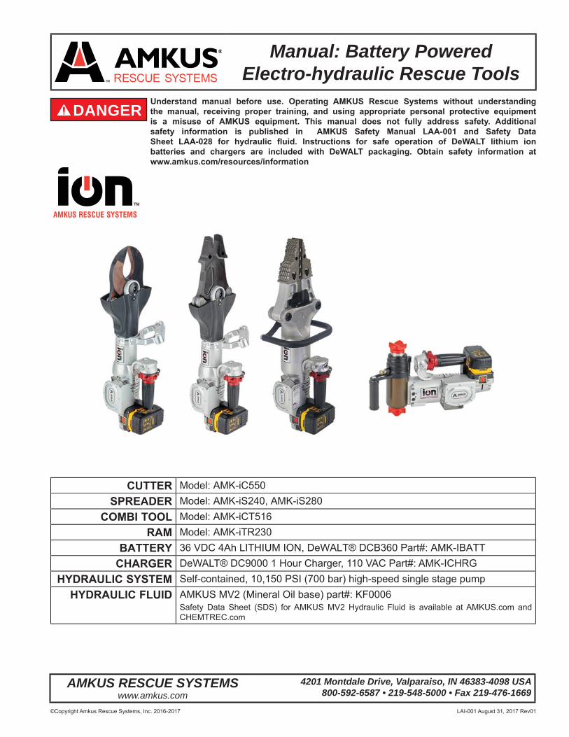
DANGERUnderstand manual before use. Operating AMKUS Rescue Systems without understanding the manual, receiving proper training, and using appropriate personal protective equipment is a misuse of AMKUS equipment. This manual does not fully address safety. Additional safety information is published in AMKUS Safety Manual LAA-001 and Safety Data Sheet LAA-028 for hydraulic fl uid. Instructions for safe operation of DeWALT lithium ion batteries and chargers are included with DeWALT packaging. Obtain safety information at www.amkus.com/resources/information
Manual: Battery Powered Electro-hydraulic Rescue Tools
AMKUS RESCUE SYSTEMSwww.amkus.com
4201 Montdale Drive, Valparaiso, IN 46383-4098 USA800-592-6587 • 219-548-5000 • Fax 219-476-1669
CUTTER Model: AMK-iC550SPREADER Model: AMK-iS240, AMK-iS280
COMBI TOOL Model: AMK-iCT516RAM Model: AMK-iTR230
BATTERY 36 VDC 4Ah LITHIUM ION, DeWALT® DCB360 Part#: AMK-IBATTCHARGER DeWALT® DC9000 1 Hour Charger, 110 VAC Part#: AMK-ICHRG
HYDRAULIC SYSTEM Self-contained, 10,150 PSI (700 bar) high-speed single stage pumpHYDRAULIC FLUID AMKUS MV2 (Mineral Oil base) part#: KF0006
Safety Data Sheet (SDS) for AMKUS MV2 Hydraulic Fluid is available at AMKUS.com and CHEMTREC.com
©Copyright Amkus Rescue Systems, Inc. 2016-2017 LAI-001 August 31, 2017 Rev012
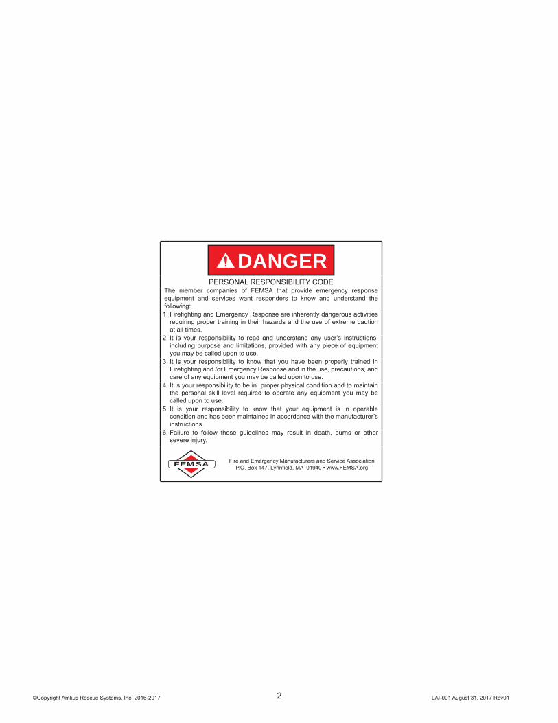
DANGERPERSONAL RESPONSIBILITY CODE
The member companies of FEMSA that provide emergency response equipment and services want responders to know and understand the following:1. Firefi ghting and Emergency Response are inherently dangerous activities
requiring proper training in their hazards and the use of extreme caution at all times.
2. It is your responsibility to read and understand any user’s instructions, including purpose and limitations, provided with any piece of equipment you may be called upon to use.
3. It is your responsibility to know that you have been properly trained in Firefi ghting and /or Emergency Response and in the use, precautions, and care of any equipment you may be called upon to use.
4. It is your responsibility to be in proper physical condition and to maintain the personal skill level required to operate any equipment you may be called upon to use.
5. It is your responsibility to know that your equipment is in operable condition and has been maintained in accordance with the manufacturer’s instructions.
6. Failure to follow these guidelines may result in death, burns or other severe injury.
FEMSA Fire and Emergency Manufacturers and Service AssociationP.O. Box 147, Lynnfi eld, MA 01940 • www.FEMSA.org
©Copyright Amkus Rescue Systems, Inc. 2016-2017 LAI-001 August 31, 2017 Rev013
©Copyright Amkus Rescue Systems, Inc. 2016 LAA-001 April 15, 2016 Rev00
DANGERUnderstand manual before use. Operating AMKUS Rescue Systems without understanding the manual, receiving proper training, and using appropriate personal protective equipment is a misuse of AMKUS equipment. Obtain safety information at www.amkus.com/
This Safety Manual is intended to familiarize rescue workers and maintenance personnel with the safety messages of AMKUS Rescue Systems, including powered rescue tools (rams, cutters, spreaders, combination tools), power units (electric or gasolinedriven), and powered rescue tool components (cable assemblies, hose assemblies, hose reels, etc.). The safety messages in this publication supersede safety information appearing in AMKUS publications prior to April 2016.
This manual is intended for use with manuals published by manufacturers of prime movers (engines, electric motors, and pumps) used in AMKUS power units.
This manual does NOT address operation or servicing of AMKUS Rescue Systems. Only competent rescue tool repair technicians are quali ed to repair AMKUS equipment. This manual should be available to all personnel involved with AMKUS equipment.
SAFETY MANUAL for AMKUS RESCUE SYSTEMS
AMKUS RESCUE SYSTEMSwww.amkus.com
4201 Montdale Drive, Valparaiso, IN 46383-4098 USA800-592-6587 • 630-515-1800 • Fax 630-515-8866
Safety information for AMKUS Electric Rescue Tools is found in document LAA-001, SAFETY MANUAL FOR AMKUS RESCUE SYSTEMS which is intended to be used in conjunction with this operations manual.
©Copyright Amkus Rescue Systems, Inc. 2015-2016 LAA-028 December 15, 2016 Rev01
SAFETY DATA SHEETAccording to OSHA Hazard Communication
Standard, 29 CFR 1910.1200
AMKUS RESCUE SYSTEMSwww.amkus.com
4201 Montdale Drive, Valparaiso, IN 46383-4098 USA800-592-6587 • 219-548-5000 • Fax 219-476-1669
SECTION 1. IDENTIFICATIONDIULF CILUARDYH 2VM SUKMAemaN tcudorP
Manufacturers of suppliers detailsAMKUS RESCUE SYSTEMS, INC.4201 Montdale DriveValparaiso, IN 46383-4098 USA
0005-845-912tseuqeR SDSCustomer ServiceEmergency telephone number
CERTMEHC 0039-424-008noitamrofnI llipS noitamrofnI htlaeH
Recommend use of the chemical and restrictions on uselio ciluardyHesU dednemmoceR
SECTION 2. HAZARDS IDENTIFICATIONGHS Classi cationNot a hazardous substance or mixtureGHS Label element
deriuqer lobmys drazah oNsmargotcip drazaHdrow langis oNdrow langiS
:SDRAZAH LACISYHPstnemetatS drazaH Not classi ed as a physical hazard under GHS criteria. HEALTH HAZARDS: Not classi ed as a health hazard under GHS criteria. ENVIRONMENTAL HAZARDS: Not classi ed as an environmental hazard under GHS criteria.
Precautionary statementsPrevention: No precautionary phrases.Response: No precautionary phrases.Storage: No precautionary phrases.Disposal: No precautionary phrases.
Other hazards which do not result in classi cationProlonged or repeated skin contact without proper cleaning can clog the pores of the skin resulting in disorders such as oil acne/folliculitis.Used oil may contain harmful impurities.High-pressure injection under the skin may cause serious damage including local necrosis.Not classi ed as ammable but will burn.The classi cation of this material is based on OSHA HCS 2012 criteria.Under normal conditions of use or in a foreseeable emergency, this product does not meet the de nition of a hazardous chemical when evaluated according to the OSHA Hazard Communication Standard, 29 CFR 1910.1200.
Safety Data Sheet (SDS) LAA-028 for AMKUS MV2 Hydraulic Fluid is available at AMKUS.com and CHEMTREC.com
©Copyright Amkus Rescue Systems, Inc. 2016-2017 LAI-001 August 31, 2017 Rev014
Table Of Contents1.0 MEANING OF SAFETY SIGNAL WORDS .....................................................................................................................................52.0 SPECIFICATIONS ..........................................................................................................................................................................5 2.1 GENERAL SPECIFICATIONS 2.2 CUTTER SPECIFICATIONS 2.3 SPREADER SPECIFICATIONS 2.4 COMBI TOOL SPECIFICATIONS 2.5 TELESCOPIC RAM SPECIFICATIONS3.0 DESCRIPTION ...............................................................................................................................................................................7 3.1 TOOL COMPONENTS 3.2 SAFETY MARKINGS4.0 SAFETY CONSIDERATIONS.........................................................................................................................................................8 4.1 PROTECTIVE CLOTHING 4.2 TRAINING 4.3 OPERATING CONSIDERATIONS5.0 SET-UP PROCEDURE ...................................................................................................................................................................8 5.1 CHARGE THE BATTERY 5.2 INSTALL THE BATTERY 5.3 POWER SWITCH ON/OFF 5.4 ROTATING HANDLE 5.4.1 HANDLE LIGHTS 5.5 CONTROL VALVE ACTUATOR6.0 OPERATION .................................................................................................................................................................................11 6.1 BATTERY CHARGE STATUS 6.2 WHEN TO CHANGE THE BATTERY 6.3 CUTTING 6.4 SPREADING / SQUEEZING / LIFTING 6.5 TELESCOPING RAM OPERATION7.0 ACCESSORIES ............................................................................................................................................................................14 7.1 RAM EXTENSIONS 7.2 EXTENDED REACH SPREADER TIPS 7.3 CHAIN USE8.0 SAFETY GUARDS .......................................................................................................................................................................169.0 MAINTENANCE ...........................................................................................................................................................................17 9.1 ROUTINE MAINTENANCE 9.1.1 CHECK THE BLADES 9.1.2 HYDRAULIC MAINTENANCE 9.1.3 MOTOR MAINTENANCE 9.1.4 GREASE THE CENTER PIN 9.1.5 HANDLE LIGHT BATTERY REPLACEMENT10.0 TROUBLESHOOTING ...............................................................................................................................................................19 10.1 GENERAL 10.2 TROUBLESHOOTING THE MOTOR 10.3 TROUBLESHOOTING THE HYDRAULICS11.0 INSPECTION, CLEANING, DECONTAMINATION, AND STORAGE ...................................................................... Back Cover12.0 PARTS, SERVICE AND TECHNICAL INFORMATION ............................................................................................. Back Cover
©Copyright Amkus Rescue Systems, Inc. 2016-2017 LAI-001 August 31, 2017 Rev015
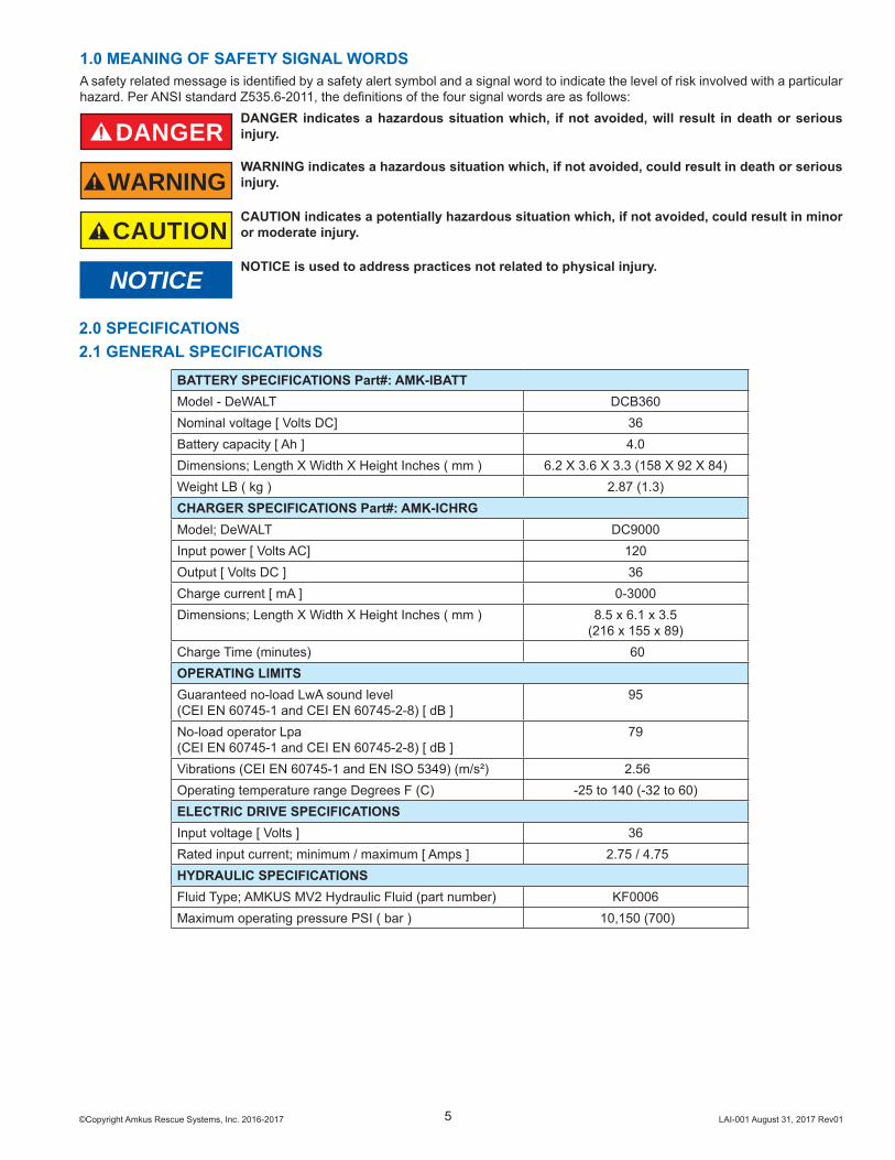
1.0 MEANING OF SAFETY SIGNAL WORDSA safety related message is identifi ed by a safety alert symbol and a signal word to indicate the level of risk involved with a particular hazard. Per ANSI standard Z535.6-2011, the defi nitions of the four signal words are as follows:
DANGERDANGER indicates a hazardous situation which, if not avoided, will result in death or serious injury.
WARNINGWARNING indicates a hazardous situation which, if not avoided, could result in death or serious injury.
CAUTIONCAUTION indicates a potentially hazardous situation which, if not avoided, could result in minor or moderate injury.
NOTICENOTICE is used to address practices not related to physical injury.
2.0 SPECIFICATIONS2.1 GENERAL SPECIFICATIONS
BATTERY SPECIFICATIONS Part#: AMK-IBATTModel - DeWALT DCB360Nominal voltage [ Volts DC] 36Battery capacity [ Ah ] 4.0Dimensions; Length X Width X Height Inches ( mm ) 6.2 X 3.6 X 3.3 (158 X 92 X 84)Weight LB ( kg ) 2.87 (1.3)CHARGER SPECIFICATIONS Part#: AMK-ICHRGModel; DeWALT DC9000Input power [ Volts AC] 120Output [ Volts DC ] 36Charge current [ mA ] 0-3000Dimensions; Length X Width X Height Inches ( mm ) 8.5 x 6.1 x 3.5
(216 x 155 x 89)Charge Time (minutes) 60OPERATING LIMITSGuaranteed no-load LwA sound level (CEI EN 60745-1 and CEI EN 60745-2-8) [ dB ]
95
No-load operator Lpa (CEI EN 60745-1 and CEI EN 60745-2-8) [ dB ]
79
Vibrations (CEI EN 60745-1 and EN ISO 5349) (m/s²) 2.56Operating temperature range Degrees F (C) -25 to 140 (-32 to 60)ELECTRIC DRIVE SPECIFICATIONSInput voltage [ Volts ] 36Rated input current; minimum / maximum [ Amps ] 2.75 / 4.75HYDRAULIC SPECIFICATIONSFluid Type; AMKUS MV2 Hydraulic Fluid (part number) KF0006Maximum operating pressure PSI ( bar ) 10,150 (700)
©Copyright Amkus Rescue Systems, Inc. 2016-2017 LAI-001 August 31, 2017 Rev016
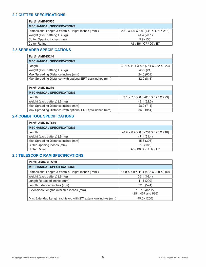
2.2 CUTTER SPECIFICATIONS Part#: AMK-iC550MECHANICAL SPECIFICATIONSDimensions; Length X Width X Height Inches ( mm ) 29.2 X 6.9 X 8.6 (741 X 175 X 218)Weight (excl. battery) LB (kg) 44.4 (20.1)Cutter Opening inches (mm) 5.9 (150)Cutter Rating A6 / B6 / C7 / D7 / E7
2.3 SPREADER SPECIFICATIONS Part#: AMK-iS240MECHANICAL SPECIFICATIONSLength 30.1 X 11.1 X 8.8 (764 X 282 X 223)Weight (excl. battery) LB (kg) 46.2 (21)Max Spreading Distance inches (mm) 24.0 (609)Max Spreading Distance (with optional ERT tips) inches (mm) 32.0 (813)
Part#: AMK-iS280MECHANICAL SPECIFICATIONSLength 32.1 X 7.0 X 8.8 (815 X 177 X 223)Weight (excl. battery) LB (kg) 49.1 (22.3)Max Spreading Distance inches (mm) 28.0 (711)Max Spreading Distance (with optional ERT tips) inches (mm) 36.0 (914)
2.4 COMBI TOOL SPECIFICATIONS Part#: AMK-iCT516MECHANICAL SPECIFICATIONSLength 28.9 X 6.9 X 8.6 (734 X 175 X 218)Weight (excl. battery) LB (kg) 47.1 (21.4)Max Spreading Distance inches (mm) 15.6 (396)Cutter Opening inches (mm) 7.3 (185)Cutter Rating A6 / B6 / C6 / D7 / E7
2.5 TELESCOPIC RAM SPECIFICATIONS Part#: AMK- iTR230MECHANICAL SPECIFICATIONSDimensions; Length X Width X Height Inches ( mm ) 17.0 X 7.9 X 11.4 (432 X 200 X 290)Weight (excl. battery) LB (kg) 36.1 (16.4)Length Retracted inches (mm) 11.4 (290)Length Extended inches (mm) 22.6 (574)Extensions Lengths Available inches (mm) 10, 18 and 27
(254, 457 and 686)Max Extended Length (achieved with 27” extension) inches (mm) 49.6 (1260)
©Copyright Amkus Rescue Systems, Inc. 2016-2017 LAI-001 August 31, 2017 Rev017
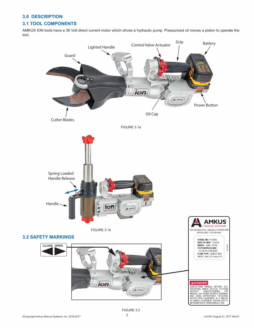
3.0 DESCRIPTION3.1 TOOL COMPONENTSAMKUS ION tools have a 36 Volt direct current motor which drives a hydraulic pump. Pressurized oil moves a piston to operate the tool.
Cutter Blades
GripControl Valve Actuator Battery
Guard
Lighted Handle
Oil Cap
Power Button
FIGURE 3.1a
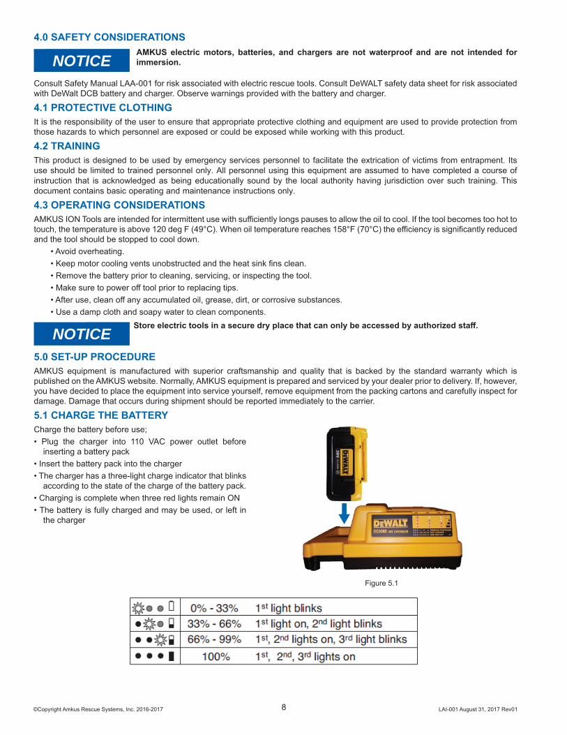
Handle
Spring LoadedHandle Release
FIGURE 3.1b
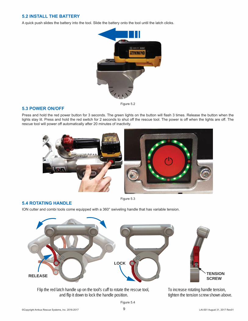
3.2 SAFETY MARKINGSOPENCLOSE
FIGURE 3.2
4201 Montdale Drive, Valparaiso, IN 46383-4098800-592-6587 • 219-548-4000
KE
L000
1
UNDERSTAND MANUAL BEFORE USE. OPERATING AMKUS RESCUE SYSTEMS WITHOUT UNDERSTANDING THE MANUAL, RECEIVING PROPER TRAINING, AND USING APPROPRIATE PERSONAL PROTECTION EQUIPMENT IS A MISUSE OF AMKUS EQUIPMENT. OBTAIN SAFETY INFORMATION AT WWW.AMKUS.COM
DANGER
SERIAL NO: K123456DATE OF MFG: 12/2016MODEL: AMK—IC550SYSTEM PRESSURE: 10,150 PSI (700 BAR)FLUID TYPE: AMKUS MV236VDC, lmin 2.75, lmax 4.75
©Copyright Amkus Rescue Systems, Inc. 2016-2017 LAI-001 August 31, 2017 Rev018
4.0 SAFETY CONSIDERATIONS
NOTICEAMKUS electric motors, batteries, and chargers are not waterproof and are not intended for immersion.
Consult Safety Manual LAA-001 for risk associated with electric rescue tools. Consult DeWALT safety data sheet for risk associated with DeWalt DCB battery and charger. Observe warnings provided with the battery and charger.
4.1 PROTECTIVE CLOTHINGIt is the responsibility of the user to ensure that appropriate protective clothing and equipment are used to provide protection from those hazards to which personnel are exposed or could be exposed while working with this product.
4.2 TRAININGThis product is designed to be used by emergency services personnel to facilitate the extrication of victims from entrapment. Its use should be limited to trained personnel only. All personnel using this equipment are assumed to have completed a course of instruction that is acknowledged as being educationally sound by the local authority having jurisdiction over such training. This document contains basic operating and maintenance instructions only.
4.3 OPERATING CONSIDERATIONSAMKUS ION Tools are intended for intermittent use with suffi ciently longs pauses to allow the oil to cool. If the tool becomes too hot to touch, the temperature is above 120 deg F (49°C). When oil temperature reaches 158°F (70°C) the effi ciency is signifi cantly reduced and the tool should be stopped to cool down.
• Avoid overheating.• Keep motor cooling vents unobstructed and the heat sink fi ns clean.• Remove the battery prior to cleaning, servicing, or inspecting the tool.• Make sure to power off tool prior to replacing tips.• After use, clean off any accumulated oil, grease, dirt, or corrosive substances.• Use a damp cloth and soapy water to clean components.
NOTICEStore electric tools in a secure dry place that can only be accessed by authorized staff .
5.0 SET-UP PROCEDUREAMKUS equipment is manufactured with superior craftsmanship and quality that is backed by the standard warranty which is published on the AMKUS website. Normally, AMKUS equipment is prepared and serviced by your dealer prior to delivery. If, however, you have decided to place the equipment into service yourself, remove equipment from the packing cartons and carefully inspect for damage. Damage that occurs during shipment should be reported immediately to the carrier.
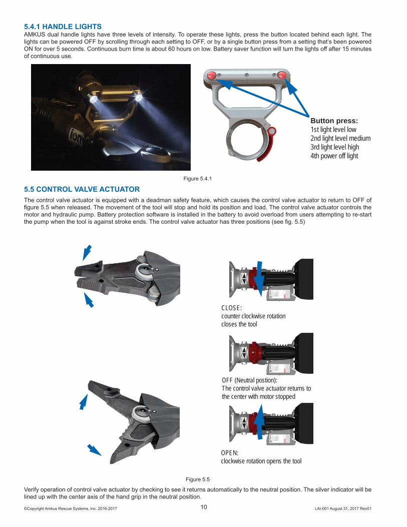
5.1 CHARGE THE BATTERYCharge the battery before use;• Plug the charger into 110 VAC power outlet before
inserting a battery pack• Insert the battery pack into the charger• The charger has a three-light charge indicator that blinks
according to the state of the charge of the battery pack.• Charging is complete when three red lights remain ON• The battery is fully charged and may be used, or left in
the charger
Figure 5.1
©Copyright Amkus Rescue Systems, Inc. 2016-2017 LAI-001 August 31, 2017 Rev019
5.2 INSTALL THE BATTERYA quick push slides the battery into the tool. Slide the battery onto the tool until the latch clicks.
Figure 5.25.3 POWER ON/OFFPress and hold the red power button for 3 seconds. The green lights on the button will fl ash 3 times. Release the button when the lights stay lit. Press and hold the red switch for 2 seconds to shut off the rescue tool. The power is off when the lights are off . The rescue tool will power off automatically after 20 minutes of inactivity.
Figure 5.35.4 ROTATING HANDLEION cutter and combi tools come equipped with a 360° swiveling handle that has variable tension.
RELEASE
LOCK
TENSION SCREW
To increase rotating handle tension, tighten the tension screw shown above.
Flip the red latch handle up on the tool’s cuff to rotate the rescue tool, and flip it down to lock the handle position.
Figure 5.4
©Copyright Amkus Rescue Systems, Inc. 2016-2017 LAI-001 August 31, 2017 Rev0110
5.4.1 HANDLE LIGHTSAMKUS dual handle lights have three levels of intensity. To operate these lights, press the button located behind each light. The lights can be powered OFF by scrolling through each setting to OFF, or by a single button press from a setting that’s been powered ON for over 5 seconds. Continuous burn time is about 60 hours on low. Battery saver function will turn the lights off after 15 minutes of continuous use.
Button press:1st light level low2nd light level medium3rd light level high4th power off light
Figure 5.4.1
5.5 CONTROL VALVE ACTUATORThe control valve actuator is equipped with a deadman safety feature, which causes the control valve actuator to return to OFF of fi gure 5.5 when released. The movement of the tool will stop and hold its position and load. The control valve actuator controls the motor and hydraulic pump. Battery protection software is installed in the battery to avoid overload from users attempting to re-start the pump when the tool is against stroke ends. The control valve actuator has three positions (see fi g. 5.5)
CLOSE: counter clockwise rotation closes the tool
OFF (Neutral postion): The control valve actuator returns to the center with motor stopped
OPEN: clockwise rotation opens the tool
Figure 5.5
Verify operation of control valve actuator by checking to see it returns automatically to the neutral position. The silver indicator will be lined up with the center axis of the hand grip in the neutral position.
©Copyright Amkus Rescue Systems, Inc. 2016-2017 LAI-001 August 31, 2017 Rev0111
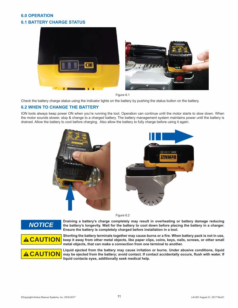
6.0 OPERATION6.1 BATTERY CHARGE STATUS
Figure 6.1
Check the battery charge status using the indicator lights on the battery by pushing the status button on the battery.
6.2 WHEN TO CHANGE THE BATTERYION tools always keep power ON when you’re running the tool. Operation can continue until the motor starts to slow down. When the motor sounds slower, stop & change to a charged battery. The battery management system maintains power until the battery is drained. Allow the battery to cool before charging. Also allow the battery to fully charge before using it again.
Figure 6.2
NOTICEDraining a battery’s charge completely may result in overheating or battery damage reducing the battery’s longevity. Wait for the battery to cool down before placing the battery in a charger. Ensure the battery is completely charged before installation in a tool.
CAUTIONShorting the battery terminals together may cause burns or a fi re. When battery pack is not in use, keep it away from other metal objects, like paper clips, coins, keys, nails, screws, or other small metal objects, that can make a connection from one terminal to another.
CAUTIONLiquid ejected from the battery may cause irritation or burns. Under abusive conditions, liquid may be ejected from the battery; avoid contact. If contact accidentally occurs, fl ush with water. If liquid contacts eyes, additionally seek medical help.
©Copyright Amkus Rescue Systems, Inc. 2016-2017 LAI-001 August 31, 2017 Rev0112
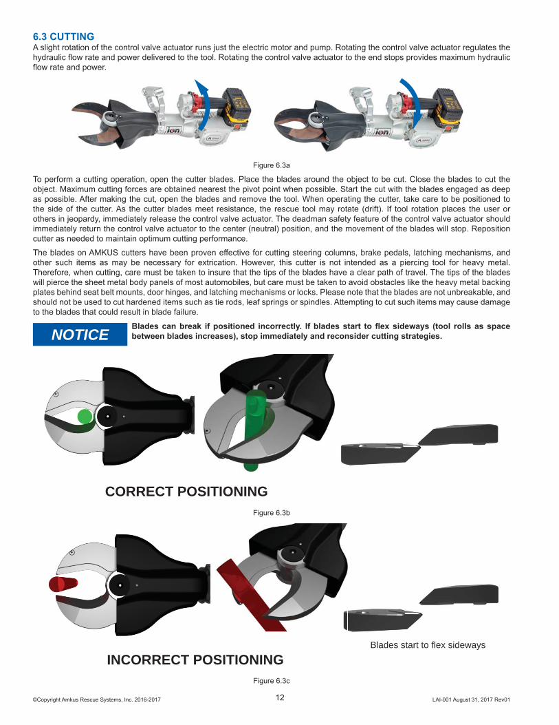
6.3 CUTTINGA slight rotation of the control valve actuator runs just the electric motor and pump. Rotating the control valve actuator regulates the hydraulic fl ow rate and power delivered to the tool. Rotating the control valve actuator to the end stops provides maximum hydraulic fl ow rate and power.
Figure 6.3a
To perform a cutting operation, open the cutter blades. Place the blades around the object to be cut. Close the blades to cut the object. Maximum cutting forces are obtained nearest the pivot point when possible. Start the cut with the blades engaged as deep as possible. After making the cut, open the blades and remove the tool. When operating the cutter, take care to be positioned to the side of the cutter. As the cutter blades meet resistance, the rescue tool may rotate (drift). If tool rotation places the user or others in jeopardy, immediately release the control valve actuator. The deadman safety feature of the control valve actuator should immediately return the control valve actuator to the center (neutral) position, and the movement of the blades will stop. Reposition cutter as needed to maintain optimum cutting performance.The blades on AMKUS cutters have been proven eff ective for cutting steering columns, brake pedals, latching mechanisms, and other such items as may be necessary for extrication. However, this cutter is not intended as a piercing tool for heavy metal. Therefore, when cutting, care must be taken to insure that the tips of the blades have a clear path of travel. The tips of the blades will pierce the sheet metal body panels of most automobiles, but care must be taken to avoid obstacles like the heavy metal backing plates behind seat belt mounts, door hinges, and latching mechanisms or locks. Please note that the blades are not unbreakable, and should not be used to cut hardened items such as tie rods, leaf springs or spindles. Attempting to cut such items may cause damage to the blades that could result in blade failure.
NOTICEBlades can break if positioned incorrectly. If blades start to fl ex sideways (tool rolls as space between blades increases), stop immediately and reconsider cutting strategies.
CORRECT POSITIONINGFigure 6.3b
INCORRECT POSITIONINGBlades start to flex sideways
Figure 6.3c
©Copyright Amkus Rescue Systems, Inc. 2016-2017 LAI-001 August 31, 2017 Rev0113
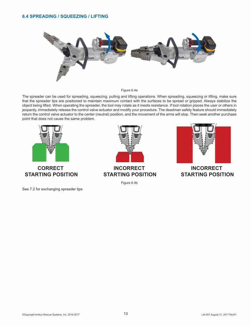
6.4 SPREADING / SQUEEZING / LIFTING
Figure 6.4a
The spreader can be used for spreading, squeezing, pulling and lifting operations. When spreading, squeezing or lifting, make sure that the spreader tips are positioned to maintain maximum contact with the surfaces to be spread or gripped. Always stabilize the object being lifted. When operating the spreader, the tool may rotate as it meets resistance. If tool rotation places the user or others in jeopardy, immediately release the control valve actuator and modify your procedure. The deadman safety feature should immediately return the control valve actuator to the center (neutral) position, and the movement of the arms will stop. Then seek another purchase point that does not cause the same problem.
CORRECT STARTING POSITION
INCORRECT STARTING POSITION
INCORRECT STARTING POSITION
Figure 6.4b
See 7.2 for exchanging spreader tips
©Copyright Amkus Rescue Systems, Inc. 2016-2017 LAI-001 August 31, 2017 Rev0114
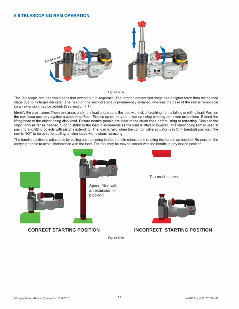
CORRECT STARTING POSITION INCORRECT STARTING POSITION
Too much space
Space filled withan extension or blocking
Figure 6.5b
6.5 TELESCOPING RAM OPERATION
Spring Release
Figure 6.5a
The Telescopic ram has two stages that extend out in sequence. The larger diameter fi rst stage has a higher force than the second stage due to its larger diameter. The head on the second stage is permanently installed, whereas the base of the ram is removable so an extension may be added. (See section 7.1)
Identify the crush zone. These are areas under the load and around the load with risk of crushing from a falling or rolling load. Position the ram base securely against a support surface. Excess space may be taken up using cribbing, or a ram extensions Extend the lifting head to the object being displaced. Ensure nearby people are clear of the crush zone before lifting or retracting. Displace the object only as far as needed. Stop to stabilize the load in increments as the load is lifted or lowered. The telescoping ram is used in pushing and lifting objects with pistons extending. The load is held when the control valve actuator is in OFF (neutral) position. The ram is NOT to be used for pulling tension loads with pistons retracting.
The handle position is adjustable by pulling out the spring loaded handle release and rotating the handle as needed. Re-position the carrying handle to avoid interference with the load. The tool may be moved carried with the handle in any locked position.
©Copyright Amkus Rescue Systems, Inc. 2016-2017 LAI-001 August 31, 2017 Rev0115
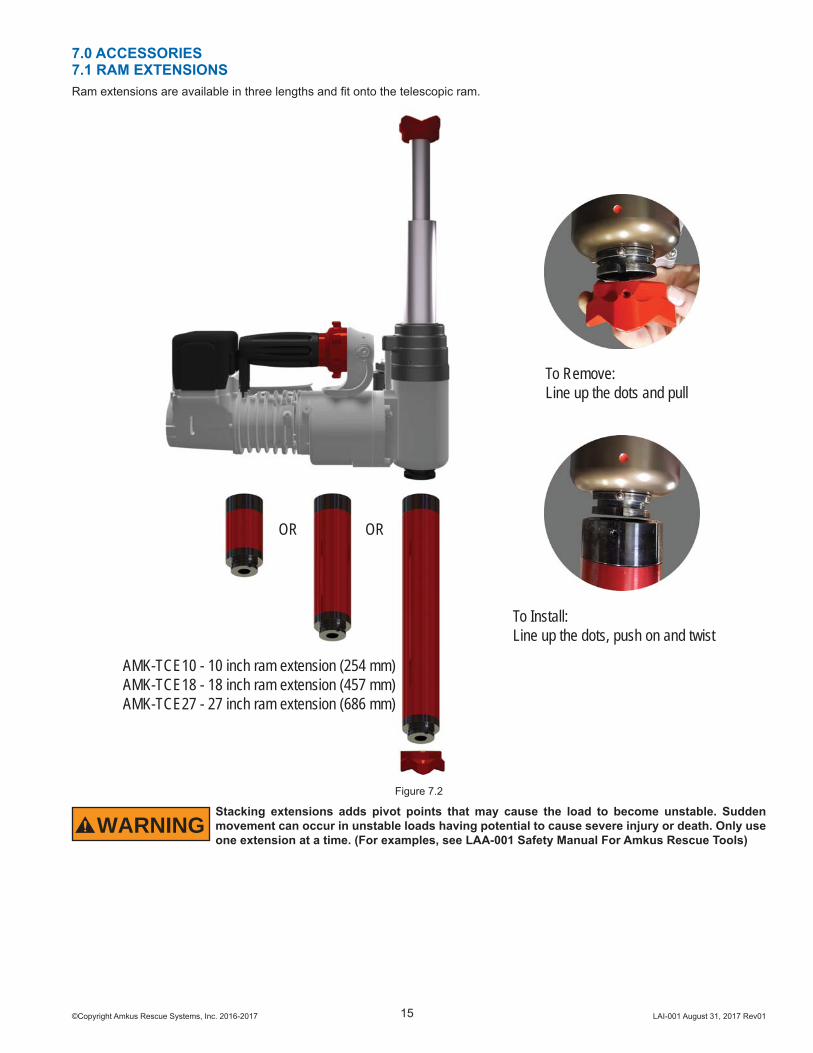
7.0 ACCESSORIES7.1 RAM EXTENSIONSRam extensions are available in three lengths and fi t onto the telescopic ram.
To Remove:Line up the dots and pull
To Install:Line up the dots, push on and twist
AMK-TCE10 - 10 inch ram extension (254 mm)AMK-TCE18 - 18 inch ram extension (457 mm)AMK-TCE27 - 27 inch ram extension (686 mm)
OR OR
Figure 7.2
WARNINGStacking extensions adds pivot points that may cause the load to become unstable. Sudden movement can occur in unstable loads having potential to cause severe injury or death. Only use one extension at a time. (For examples, see LAA-001 Safety Manual For Amkus Rescue Tools)
©Copyright Amkus Rescue Systems, Inc. 2016-2017 LAI-001 August 31, 2017 Rev0116
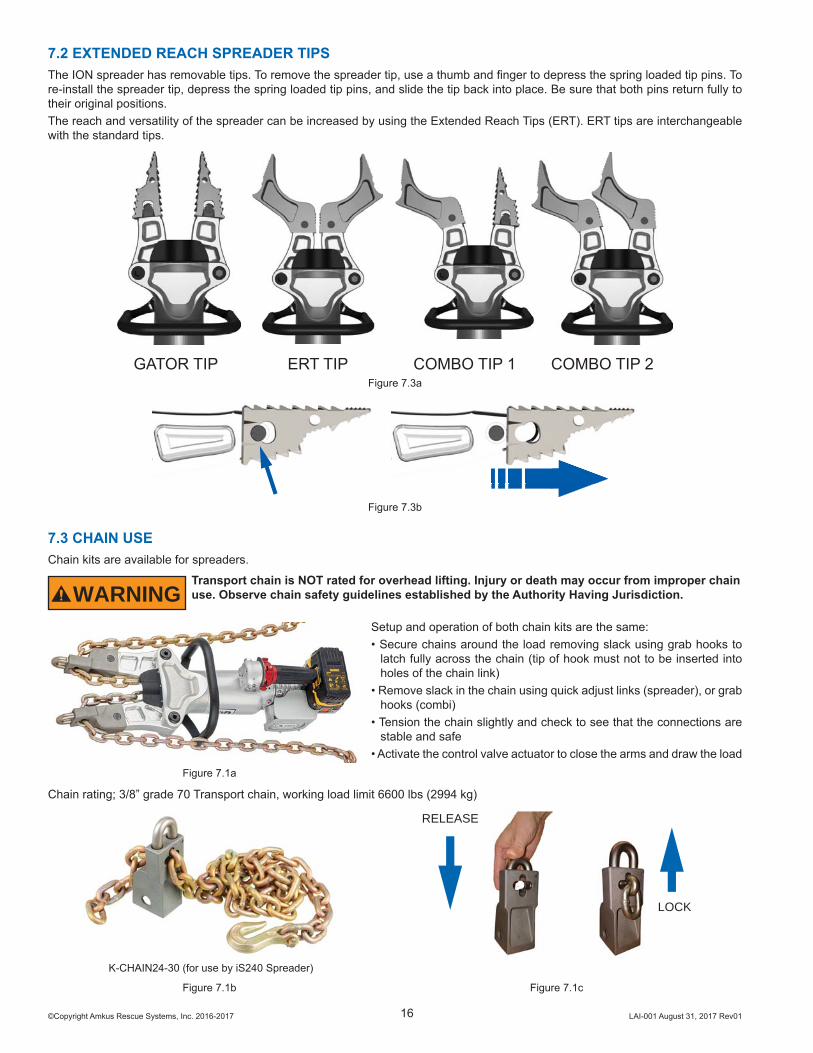
7.2 EXTENDED REACH SPREADER TIPSThe ION spreader has removable tips. To remove the spreader tip, use a thumb and fi nger to depress the spring loaded tip pins. To re-install the spreader tip, depress the spring loaded tip pins, and slide the tip back into place. Be sure that both pins return fully to their original positions. The reach and versatility of the spreader can be increased by using the Extended Reach Tips (ERT). ERT tips are interchangeable with the standard tips.
GATOR TIP ERT TIP COMBO TIP 1 COMBO TIP 2Figure 7.3a
Figure 7.3b
7.3 CHAIN USEChain kits are available for spreaders.
WARNINGTransport chain is NOT rated for overhead lifting. Injury or death may occur from improper chain use. Observe chain safety guidelines established by the Authority Having Jurisdiction.
Setup and operation of both chain kits are the same:• Secure chains around the load removing slack using grab hooks to
latch fully across the chain (tip of hook must not to be inserted into holes of the chain link)
• Remove slack in the chain using quick adjust links (spreader), or grab hooks (combi)
• Tension the chain slightly and check to see that the connections are stable and safe
• Activate the control valve actuator to close the arms and draw the loadFigure 7.1a
Chain rating; 3/8” grade 70 Transport chain, working load limit 6600 lbs (2994 kg)
RELEASE
LOCK
K-CHAIN24-30 (for use by iS240 Spreader)
Figure 7.1b Figure 7.1c
©Copyright Amkus Rescue Systems, Inc. 2016-2017 LAI-001 August 31, 2017 Rev0117
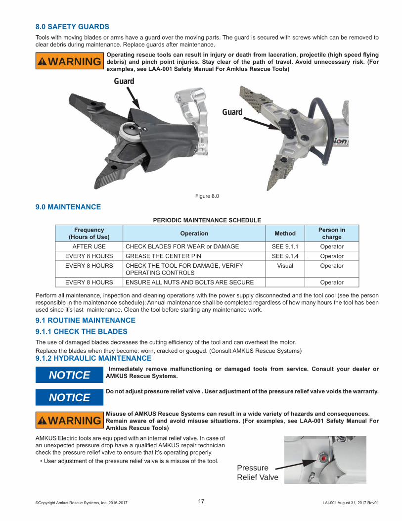
8.0 SAFETY GUARDSTools with moving blades or arms have a guard over the moving parts. The guard is secured with screws which can be removed to clear debris during maintenance. Replace guards after maintenance.
WARNINGOperating rescue tools can result in injury or death from laceration, projectile (high speed fl ying debris) and pinch point injuries. Stay clear of the path of travel. Avoid unnecessary risk. (For examples, see LAA-001 Safety Manual For Amklus Rescue Tools)
Guard
Guard
Figure 8.0
9.0 MAINTENANCEPERIODIC MAINTENANCE SCHEDULE
Frequency(Hours of Use) Operation Method Person in
chargeAFTER USE CHECK BLADES FOR WEAR or DAMAGE SEE 9.1.1 Operator
EVERY 8 HOURS GREASE THE CENTER PIN SEE 9.1.4 OperatorEVERY 8 HOURS CHECK THE TOOL FOR DAMAGE, VERIFY
OPERATING CONTROLSVisual Operator
EVERY 8 HOURS ENSURE ALL NUTS AND BOLTS ARE SECURE Operator
Perform all maintenance, inspection and cleaning operations with the power supply disconnected and the tool cool (see the person responsible in the maintenance schedule); Annual maintenance shall be completed regardless of how many hours the tool has been used since it’s last maintenance. Clean the tool before starting any maintenance work.
9.1 ROUTINE MAINTENANCE9.1.1 CHECK THE BLADESThe use of damaged blades decreases the cutting effi ciency of the tool and can overheat the motor.Replace the blades when they become: worn, cracked or gouged. (Consult AMKUS Rescue Systems)9.1.2 HYDRAULIC MAINTENANCE
NOTICE Immediately remove malfunctioning or damaged tools from service. Consult your dealer or AMKUS Rescue Systems.
NOTICEDo not adjust pressure relief valve . User adjustment of the pressure relief valve voids the warranty.
WARNINGMisuse of AMKUS Rescue Systems can result in a wide variety of hazards and consequences.Remain aware of and avoid misuse situations. (For examples, see LAA-001 Safety Manual For Amklus Rescue Tools)
AMKUS Electric tools are equipped with an internal relief valve. In case of an unexpected pressure drop have a qualifi ed AMKUS repair technician check the pressure relief valve to ensure that it’s operating properly.
• User adjustment of the pressure relief valve is a misuse of the tool.PressureRelief Valve
©Copyright Amkus Rescue Systems, Inc. 2016-2017 LAI-001 August 31, 2017 Rev0118
9.1.3 MOTOR MAINTENANCE• Keep the motor cooling vents clean and unobstructed
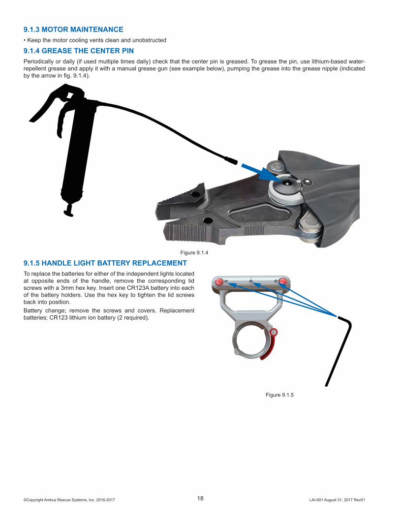
9.1.4 GREASE THE CENTER PINPeriodically or daily (if used multiple times daily) check that the center pin is greased. To grease the pin, use lithium-based water-repellent grease and apply it with a manual grease gun (see example below), pumping the grease into the grease nipple (indicated by the arrow in fi g. 9.1.4).
Figure 9.1.4
9.1.5 HANDLE LIGHT BATTERY REPLACEMENTTo replace the batteries for either of the independent lights located at opposite ends of the handle, remove the corresponding lid screws with a 3mm hex key. Insert one CR123A battery into each of the battery holders. Use the hex key to tighten the lid screws back into position.Battery change; remove the screws and covers. Replacement batteries; CR123 lithium ion battery (2 required).
Figure 9.1.5
©Copyright Amkus Rescue Systems, Inc. 2016-2017 LAI-001 August 31, 2017 Rev0119
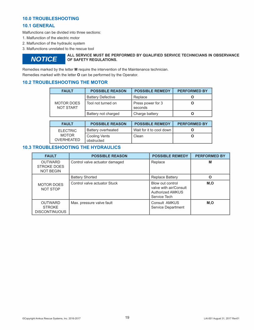
10.3 TROUBLESHOOTING THE HYDRAULICS
FAULT POSSIBLE REASON POSSIBLE REMEDY PERFORMED BYOUTWARD
STROKE DOESNOT BEGIN
Control valve actuator damaged Replace M
MOTOR DOESNOT STOP
Battery Shorted Replace Battery OControl valve actuator Stuck Blow out control
valve with air/Consult Authorized AMKUS Service Tech
M,O
OUTWARDSTROKE
DISCONTINUOUS
Max. pressure valve fault Consult AMKUS Service Department
M,O
10.2 TROUBLESHOOTING THE MOTOR
FAULT POSSIBLE REASON POSSIBLE REMEDY PERFORMED BY
MOTOR DOES NOT START
Battery Defective Replace OTool not turned on Press power for 3
secondsO
Battery not charged Charge battery O
FAULT POSSIBLE REASON POSSIBLE REMEDY PERFORMED BY
ELECTRICMOTOR
OVERHEATED
Battery overheated Wait for it to cool down OCooling Ventsobstructed
Clean O
10.0 TROUBLESHOOTING10.1 GENERALMalfunctions can be divided into three sections:1. Malfunction of the electric motor2. Malfunction of the hydraulic system3. Malfunctions unrelated to the rescue tool
NOTICEALL SERVICE MUST BE PERFORMED BY QUALIFIED SERVICE TECHNICIANS IN OBSERVANCE OF SAFETY REGULATIONS.
Remedies marked by the letter M require the intervention of the Maintenance technician.Remedies marked with the letter O can be performed by the Operator.
©Copyright Amkus Rescue Systems, Inc. 2016-2017 LAI-001 August 31, 2017 Rev01
AMKUS RESCUE SYSTEMSwww.amkus.com
4201 Montdale Drive, Valparaiso, IN 46383-4098 USA800-592-6587 • 219-548-5000 • Fax 219-476-1669
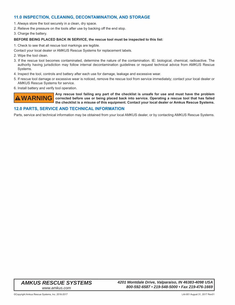
11.0 INSPECTION, CLEANING, DECONTAMINATION, AND STORAGE1. Always store the tool securely in a clean, dry space.2. Relieve the pressure on the tools after use by backing off the end stop.3. Charge the battery.
BEFORE BEING PLACED BACK IN SERVICE, the rescue tool must be inspected to this list:1. Check to see that all rescue tool markings are legible.Contact your local dealer or AMKUS Rescue Systems for replacement labels.2. Wipe the tool clean.3. If the rescue tool becomes contaminated, determine the nature of the contamination. IE: biological, chemical, radioactive. The
authority having jurisdiction may follow internal decontamination guidelines or request technical advice from AMKUS Rescue Systems.
4. Inspect the tool, controls and battery after each use for damage, leakage and excessive wear.5. If rescue tool damage or excessive wear is noticed, remove the rescue tool from service immediately; contact your local dealer or
AMKUS Rescue Systems for service.6. Install battery and verify tool operation.
WARNINGAny rescue tool failing any part of the checklist is unsafe for use and must have the problem corrected before use or being placed back into service. Operating a rescue tool that has failed the checklist is a misuse of this equipment. Contact your local dealer or Amkus Rescue Systems.
12.0 PARTS, SERVICE AND TECHNICAL INFORMATIONParts, service and technical information may be obtained from your local AMKUS dealer, or by contacting AMKUS Rescue Systems.