Embed Size (px)
Citation preview

1
Tele Radio 860Manual
IM-860-001-A3
2 3
860 TX4= Charge connector
Only 12V DC
860 TX1= Yellow LED 12= Yellow LED 2 3= Red/ Green LED 3
1
23
1 2
XStartStart
2
4
6
8
0
1
3
5
7
9
4
Only 12V DC
2 3
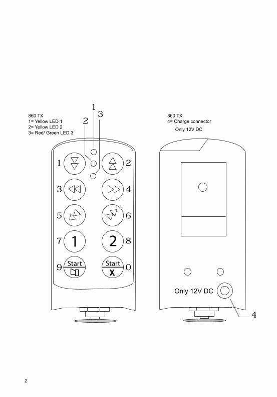
860RX1= Red LED 12= Yellow LED 23= Reset button 4= Green LED 45= Red LED 5 6= Yellow LED 6 7= Function selector switch 8= Green LED 8 9= Red LED 910= Yellow LED 10 11= Radio module12= Green LED 12
45
6
89 10
7
2
3
12
11
1
1 2 3 4 5 6 7 8 9 10 11 12 13 14 15 16 17 18 19 20 21 22 23 24 25 26 27 28 29 30 31 32 33 34 35 36 37 38 39
SR1 SR2
1 2 3 4 5 6 7 8 9 1011 12131415 2221191817 16 20 282726252423 29 30
SR2
SR1
*
* Fuse S1 0,5A cermaic fast (F) for receivers with voltage supply :48, 115 and 230V AC.
160 161
THE SYSTEM’S FUNCTIONS
Frequency:System 860 uses 32 different frequencies, which makes it possible to have several transmitters and recei-vers operating within the same coverage area.
Battery indicatorThe transmitter has a built-in battery indicator that turns red when about 10% of the battery charge remains. Total operating time is about 12 hours. Recharge time is about 2 hours.
Automatic shutdown:Tc conserve battery power, the transmitter has an integrated automatic shutdown function. Possible selections for automatic shutdown are: after 2, 6, or 12 minutes, or no automatic shutdown.
PIN code:Up to 10 individual/personal PIN codes can be programmed into each transmitter.
Logging on/off:The receiver can be programmed to accept up to three different transmitters, where each transmitter has a unique code. For security reasons, only one transmitter can be logged on at a time. In order to log on another transmitter, the current transmitter must log off first.
Function selection:The system includes the ability to program a number of different relay function combinations.
Momentary or latching relay functions:Each function relay can be programmed for a momentary or latching relay function.
Pre-sets:With this function, it is possible to pre-set/prioritize one relay function/button over another. If a pre-set is programmed and two buttons are pressed at the same time, the transmitter prioritizes/pre-sets one of the buttons over the other, which makes it impossible, for example, to activate the up and down buttons together.
The safety relay:The receiver is supplied with two safety relays, which are monitored continuously. Any failure of either safety relay will shut down the receiver.
Built-in safety function when the transmitter is started: 0-position monitoringIf any button is pressed involuntarily when the transmitter is to be started, the transmitter will not start. This is indicated by the red LED. So-called 0-position monitoring.
THE 860TX TRANSMITTER
Illustrations of the transmitter can be found on page 2.10 two-stage push buttons 32 different frequencies, 433.875 - 434.650MHz Stop button Rechargeable battery Radio: PLL Synthesizer Enclosure dimensions: 6.30x2.75x1.38 inches Weight: About 13.4 ounces Enclosure class: IP 54
SEES
FRDE
GB
US
NO
DK
NL
162 163
NO
DK
SENL
ESFR
DE
GB
US
Charging the transmitter:The transmitter is supplied with a rechargeable battery. The LED on the transmitter indicates red or green depending on battery status. Operating time for a fully charged transmitter is about 12 hours with continuous use.
When the battery needs to be recharged, the LED changes color from green to red. At that point about 10% of the battery capacity remains (approximately 1 hour of continuous use).
Note:Battery life increases if you wait for the LED to turn red before recharging. However, the battery should be recharged at least once every other month when not in use.
When recharging, the LED will be red and will change to green when fully charged (after about 2 hours). The transmitter cannot be overcharged.
Charging: 12V DC (500mA) or model TR115V12 battery charger
THE 860RX RECEIVER
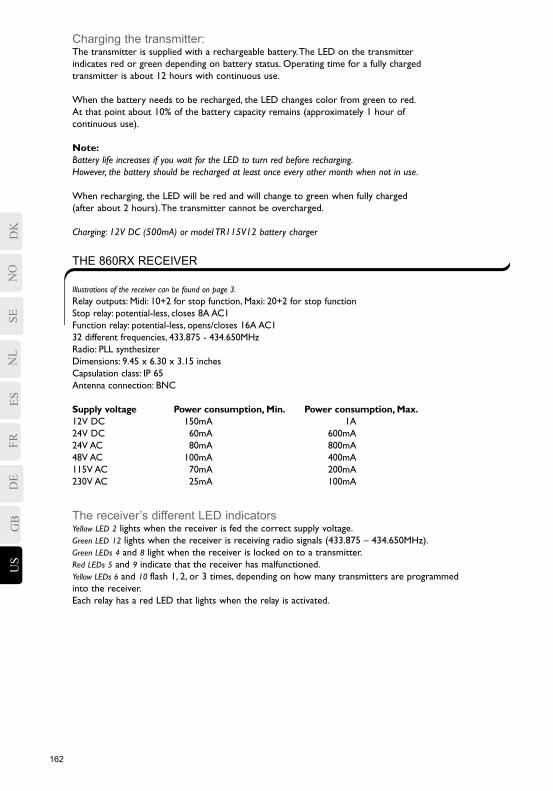
Illustrations of the receiver can be found on page 3.Relay outputs: Midi: 10+2 for stop function, Maxi: 20+2 for stop function Stop relay: potential-less, closes 8A AC1 Function relay: potential-less, opens/closes 16A AC1 32 different frequencies, 433.875 - 434.650MHz Radio: PLL synthesizer Dimensions: 9.45 x 6.30 x 3.15 inches Capsulation class: IP 65 Antenna connection: BNC
Supply voltage Power consumption, Min. Power consumption, Max. 12V DC 150mA 1A 24V DC 60mA 600mA 24V AC 80mA 800mA 48V AC 100mA 400mA 115V AC 70mA 200mA 230V AC 25mA 100mA
The receiver’s different LED indicatorsYellow LED 2 lights when the receiver is fed the correct supply voltage.Green LED 12 lights when the receiver is receiving radio signals (433.875 – 434.650MHz).Green LEDs 4 and 8 light when the receiver is locked on to a transmitter.Red LEDs 5 and 9 indicate that the receiver has malfunctioned.Yellow LEDs 6 and 10 flash 1, 2, or 3 times, depending on how many transmitters are programmed into the receiver.Each relay has a red LED that lights when the relay is activated.
162 163
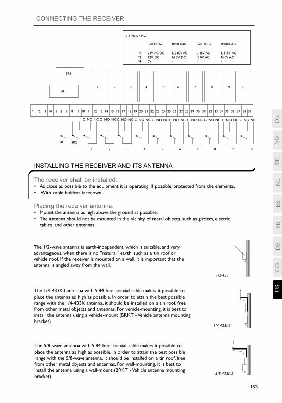
CONNECTING THE RECEIVER
INSTALLING THE RECEIVER AND ITS ANTENNA
The receiver shall be installed:• As close as possible to the equipment it is operating. If possible, protected from the elements.• With cable holders facedown.
Placing the receiver antenna:• Mount the antenna as high above the ground as possible.• The antenna should not be mounted in the vicinity of metal objects, such as girders, electric cables, and other antennas.
The 1/2-wave antenna is earth-independent, which is suitable, and very advantageous, when there is no ”natural” earth, such as a tin roof or vehicle roof. If the receiver is mounted on a wall, it is important that the antenna is angled away from the wall.
The 1/4-433K3 antenna with 9.84 foot coaxial cable makes it possible to place the antenna as high as possible. In order to attain the best possible range with the 1/4-433K antenna, it should be installed on a tin roof, free from other metal objects and antennas. For vehicle-mounting, it is best to install the antenna using a vehicle-mount (BRKT - Vehicle antenna mounting bracket).
The 5/8-wave antenna with 9.84 foot coaxial cable makes it possible to place the antenna as high as possible. In order to attain the best possible range with the 5/8-wave antenna, it should be installed on a tin roof, free from other metal objects and antennas. For wall-mounting, it is best to install the antenna using a wall-mount (BRKT - Vehicle antenna mounting bracket).
1/2-433
1/4-433K3
5/8-433K3
SEES
FRDE
GB
US
NO
DK
NL
C NO NC C NO NCC NO NC C NO NC C NO NC C NO NC C NO NC
*1 *2 *4 6 7 8 9 10 11 1412 13 15 16 17 18 19 20 21 22 23 24 25 27 28 29 30 31 3226
SR2
1 2 3 4 5 6
SR1
1 2 3
C NO NC C NO NC C NO NC
33 34 35 36 37 38 39
7 8 9 10
SR1
SR1
3 5
4 5 6 7 8 9 10
x = Miidi / Maxi 860RX-Ax 860RX-Bx 860RX-Cx 860RX-Dx
*1 24V AC/DC L 230V AC L 48V AC L 115V AC *2 12V DC N 0V DC N 0V AC N 0V AC *4 0V - - -
164 165
NO
DK
SENL
ESFR
DE
GB
US
ON THE RECEIVER:
1) Set switch 2 of the function selection dip switch to the ON position.2) Press the reset button.. Green (4 and 8), red (5 and 9), and yellow (6 and 10) LEDs light.3) Release the reset button. Green (4 and 8) and red (5 and 9) LEDs go out. Yellow (6 and 10) LEDs light. If the red and yellow LEDs flash alternately, this means that 3 transmitters are programmed into the receiver.4) Set switch 2 to the OFF position.5) Set switch 2 to the ON position within 2 seconds. The yellow (6 and 10) LEDs flash and the receiver is deleted.6) Set switch 2 to the OFF position.
DELETING ALL TRANSMITTERS IN THE RECEIVER
1) The stop button must be pulled out.2) Press the start buttons (buttons 9 and 10) at the same time for at least 1 second.3) Release the start buttons.4) To indicate that the transmitter is operational, LED 3 lights green.
STARTING THE TRANSMITTER
1) The stop button must be pulled out.2) Press the start buttons (buttons 9 and 10) at the same time for at least 1 second.3) Release the buttons. Yellow (2) and green (3) LEDs flash.4) Enter the PIN code (4 digits). Green LED (3) lights. If an incorrect PIN code is entered, the transmitter will shut down.
STARTING A TRANSMITTER WITH A PIN CODE:
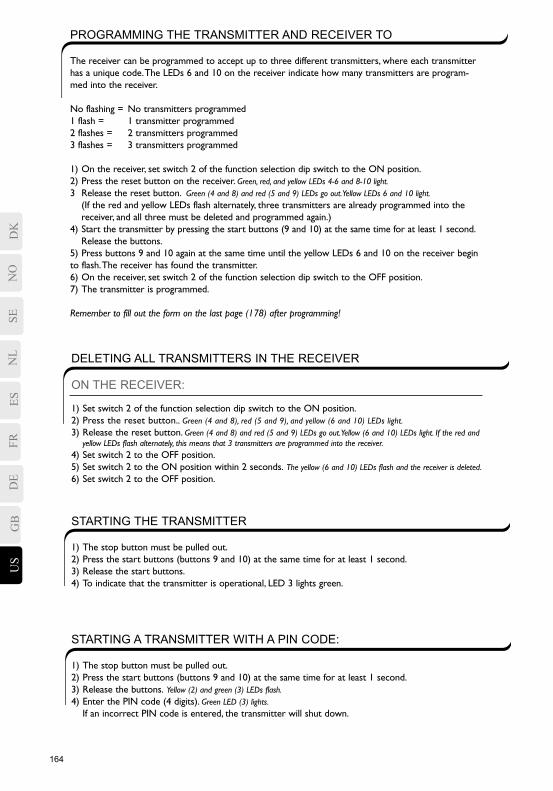
PROGRAMMING THE TRANSMITTER AND RECEIVER TO
The receiver can be programmed to accept up to three different transmitters, where each transmitter has a unique code. The LEDs 6 and 10 on the receiver indicate how many transmitters are program-med into the receiver.
No flashing = No transmitters programmed1 flash = 1 transmitter programmed2 flashes = 2 transmitters programmed3 flashes = 3 transmitters programmed
1) On the receiver, set switch 2 of the function selection dip switch to the ON position.2) Press the reset button on the receiver. Green, red, and yellow LEDs 4-6 and 8-10 light.3 Release the reset button. Green (4 and 8) and red (5 and 9) LEDs go out. Yellow LEDs 6 and 10 light. (If the red and yellow LEDs flash alternately, three transmitters are already programmed into the receiver, and all three must be deleted and programmed again.)4) Start the transmitter by pressing the start buttons (9 and 10) at the same time for at least 1 second. Release the buttons.5) Press buttons 9 and 10 again at the same time until the yellow LEDs 6 and 10 on the receiver begin to flash. The receiver has found the transmitter.6) On the receiver, set switch 2 of the function selection dip switch to the OFF position.7) The transmitter is programmed.
Remember to fill out the form on the last page (178) after programming!
164 165
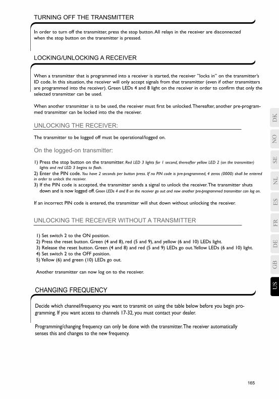
When a transmitter that is programmed into a receiver is started, the receiver ”locks in” on the transmitter’s ID code. In this situation, the receiver will only accept signals from that transmitter (even if other transmitters are programmed into the receiver). Green LEDs 4 and 8 light on the receiver in order to confirm that only the selected transmitter can be used.
When another transmitter is to be used, the receiver must first be unlocked. Thereafter, another pre-program-med transmitter can be locked into the the receiver.
UNLOCKING THE RECEIVER:
The transmitter to be logged off must be operational/logged on.
On the logged-on transmitter:
1) Press the stop button on the transmitter. Red LED 3 lights for 1 second, thereafter yellow LED 2 (on the transmitter) lights and red LED 3 begins to flash.2) Enter the PIN code. You have 2 seconds per button press. If no PIN code is pre-programmed, 4 zeros (0000) shall be entered in order to unlock the receiver.3) If the PIN code is accepted, the transmitter sends a signal to unlock the receiver. The transmitter shuts down and is now logged off. Green LEDs 4 and 8 on the receiver go out and now another pre-programmed transmitter can log on.
If an incorrect PIN code is entered, the transmitter will shut down without unlocking the receiver.
TURNING OFF THE TRANSMITTER
In order to turn off the transmitter, press the stop button. All relays in the receiver are disconnected when the stop button on the transmitter is pressed.
LOCKING/UNLOCKING A RECEIVER
UNLOCKING THE RECEIVER WITHOUT A TRANSMITTER
1) Set switch 2 to the ON position.2) Press the reset button. Green (4 and 8), red (5 and 9), and yellow (6 and 10) LEDs light.3) Release the reset button. Green (4 and 8) and red (5 and 9) LEDs go out. Yellow LEDs (6 and 10) light.4) Set switch 2 to the OFF position.5) Yellow (6) and green (10) LEDs go out.
Another transmitter can now log on to the receiver.
CHANGING FREQUENCY
Decide which channel/frequency you want to transmit on using the table below before you begin pro-gramming. If you want access to channels 17-32, you must contact your dealer.
Programming/changing frequency can only be done with the transmitter. The receiver automatically senses this and changes to the new frequency.
SEES
FRDE
GB
US
NO
DK
NL
166 167
NO
DK
SENL
ESFR
DE
GB
US
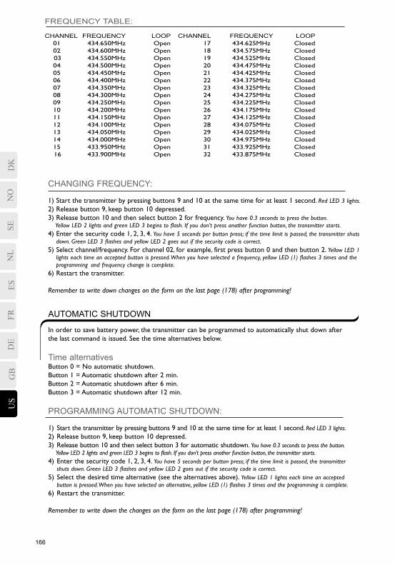
FREQUENCY TABLE:
CHANNEL FREQUENCY LOOP CHANNEL FREQUENCY LOOP 01 434.650MHz Open 17 434.625MHz Closed 02 434.600MHz Open 18 434.575MHz Closed 03 434.550MHz Open 19 434.525MHz Closed 04 434.500MHz Open 20 434.475MHz Closed 05 434.450MHz Open 21 434.425MHz Closed 06 434.400MHz Open 22 434.375MHz Closed 07 434.350MHz Open 23 434.325MHz Closed 08 434.300MHz Open 24 434.275MHz Closed 09 434.250MHz Open 25 434.225MHz Closed 10 434.200MHz Open 26 434.175MHz Closed 11 434.150MHz Open 27 434.125MHz Closed 12 434.100MHz Open 28 434.075MHz Closed 13 434.050MHz Open 29 434.025MHz Closed 14 434.000MHz Open 30 434.975MHz Closed 15 433.950MHz Open 31 433.925MHz Closed 16 433.900MHz Open 32 433.875MHz Closed
CHANGING FREQUENCY:
1) Start the transmitter by pressing buttons 9 and 10 at the same time for at least 1 second. Red LED 3 lights.2) Release button 9, keep button 10 depressed.3) Release button 10 and then select button 2 for frequency. You have 0.3 seconds to press the button. Yellow LED 2 lights and green LED 3 begins to flash. If you don’t press another function button, the transmitter starts.4) Enter the security code 1, 2, 3, 4. You have 5 seconds per button press; if the time limit is passed, the transmitter shuts down. Green LED 3 flashes and yellow LED 2 goes out if the security code is correct.5) Select channel/frequency. For channel 02, for example, first press button 0 and then button 2. Yellow LED 1 lights each time an accepted button is pressed. When you have selected a frequency, yellow LED (1) flashes 3 times and the programming and frequency change is complete.6) Restart the transmitter.
Remember to write down changes on the form on the last page (178) after programming!
AUTOMATIC SHUTDOWN
In order to save battery power, the transmitter can be programmed to automatically shut down after the last command is issued. See the time alternatives below.
Time alternativesButton 0 = No automatic shutdown.Button 1 = Automatic shutdown after 2 min.Button 2 = Automatic shutdown after 6 min.Button 3 = Automatic shutdown after 12 min.
PROGRAMMING AUTOMATIC SHUTDOWN:
1) Start the transmitter by pressing buttons 9 and 10 at the same time for at least 1 second. Red LED 3 lights.2) Release button 9, keep button 10 depressed.3) Release button 10 and then select button 3 for automatic shutdown. You have 0.3 seconds to press the button. Yellow LED 2 lights and green LED 3 begins to flash. If you don’t press another function button, the transmitter starts.4) Enter the security code 1, 2, 3, 4. You have 5 seconds per button press; if the time limit is passed, the transmitter shuts down. Green LED 3 flashes and yellow LED 2 goes out if the security code is correct.5) Select the desired time alternative (see the alternatives above). Yellow LED 1 lights each time an accepted button is pressed. When you have selected an alternative, yellow LED (1) flashes 3 times and the programming is complete.6) Restart the transmitter.
Remember to write down the changes on the form on the last page (178) after programming!
166 167
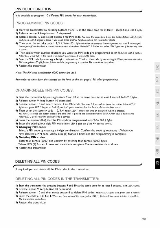
PIN CODE FUNCTION
It is possible to program 10 different PIN codes for each transmitter.
PROGRAMMING PIN CODES:
1) Start the transmitter by pressing buttons 9 and 10 at the same time for at least 1 second. Red LED 3 lights.2) Release button 9, keep button 10 depressed.3) Release button 10 and select button 4 for PIN code. You have 0.3 seconds to press the button. Yellow LED 2 lights and green LED 3 begins to flash. If you don’t press another function button, the transmitter starts.4) Then enter the security code 1, 2, 3, 4. Yellow LED 1 lights each time an accepted button is pressed. You have 5 seconds per button press; if the time limit is passed, the transmitter shuts down. Green LED 3 flashes and yellow LED 2 goes out if the security code is correct.5) Then select which number (button) you want the PIN code pre-programmed to (0-9). Green LED 3 flashes. Yellow LED 2 will light if the number is already programmed with a PIN code.6) Select a PIN code by entering a 4-digit combination. Confirm the code by repeating it. When you have selected a PIN code, yellow LED (1) flashes 3 times and the programming is complete. The transmitter shuts down.7) Restart the transmitter.
Note: The PIN code combination 0000 cannot be used.
Remember to write down the changes on the form on the last page (178) after programming!
DELETING ALL PIN CODES IN THE TRANSMITTER:
1) Start the transmitter by pressing buttons 9 and 10 at the same time for at least 1 second. Red LED 3 lights.2) Release button 9, keep button 10 depressed.3) Release button 10 and then select button 8 to delete PIN codes. Yellow LED 2 lights and green LED 3 flashes.4) Enter the code 7, 1, 0, 4, 2, 1. When you have entered the code, yellow LED (1) flashes 3 times and deletion is complete. The transmitter shuts down.5) Restart the transmitter.
CHANGING/DELETING PIN CODES:
1) Start the transmitter by pressing buttons 9 and 10 at the same time for at least 1 second. Red LED 3 lights.2) Release button 9, keep button 10 depressed.3) Release button 10 and select button 4 for PIN code. You have 0.3 seconds to press the button. Yellow LED 2 lights and green LED 3 begins to flash. If you don’t press another function button, the transmitter starts.4) Then enter the security code 1, 2, 3, 4. Yellow LED 1 lights each time an accepted button is pressed. You have 5 seconds per button press; if the time limit is passed, the transmitter shuts down. Green LED 3 flashes and yellow LED 2 goes out if the security code is correct.5) Press the number (0-9) that the PIN code is programmed into. Yellow LED 2 lights.6) Enter the existing four-digit PIN code. Yellow LED 2 goes out if the PIN code is correct.7) Changing PIN code: Select a PIN code by entering a 4-digit combination. Confirm the code by repeating it. When you have selected a PIN code, yellow LED (1) flashes 3 times and the programming is complete.8) Deleting PIN codes Enter four zeroes (0000) and confirm by entering four zeroes (0000) again. Yellow LED (1) flashes 3 times and deletion is complete. The transmitter shuts down.9) Restart the transmitter.
DELETING ALL PIN CODES
If required, you can delete all the PIN codes in the transmitter.
SEES
FRDE
GB
US
NO
DK
NL
168 169
NO
DK
SENL
ESFR
DE
GB
US
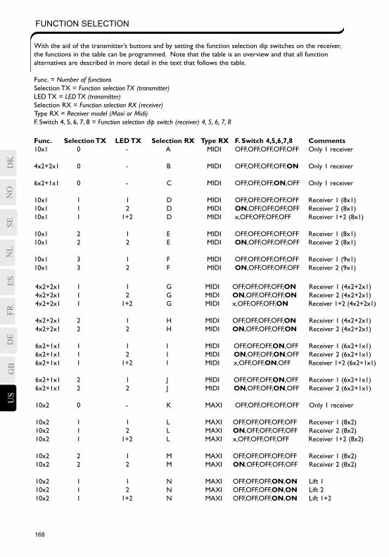
FUNCTION SELECTION
With the aid of the transmitter’s buttons and by setting the function selection dip switches on the receiver, the functions in the table can be programmed. Note that the table is an overview and that all function alternatives are described in more detail in the text that follows the table.
Func. = Number of functionsSelection TX = Function selection TX (transmitter)LED TX = LED TX (transmitter)Selection RX = Function selection RX (receiver)Type RX = Receiver model (Maxi or Midi)F. Switch 4, 5, 6, 7, 8 = Function selection dip switch (receiver) 4, 5, 6, 7, 8
Func. Selection TX LED TX Selection RX Type RX F. Switch 4,5,6,7,8 Comments10x1 0 - A MIDI OFF,OFF,OFF,OFF,OFF Only 1 receiver
4x2+2x1 0 - B MIDI OFF,OFF,OFF,OFF,ON Only 1 receiver
6x2+1x1 0 - C MIDI OFF,OFF,OFF,ON,OFF Only 1 receiver
10x1 1 1 D MIDI OFF,OFF,OFF,OFF,OFF Receiver 1 (8x1)10x1 1 2 D MIDI ON,OFF,OFF,OFF,OFF Receiver 2 (8x1)10x1 1 1+2 D MIDI x,OFF,OFF,OFF,OFF Receiver 1+2 (8x1)
10x1 2 1 E MIDI OFF,OFF,OFF,OFF,OFF Receiver 1 (8x1)10x1 2 2 E MIDI ON,OFF,OFF,OFF,OFF Receiver 2 (8x1)
10x1 3 1 F MIDI OFF,OFF,OFF,OFF,OFF Receiver 1 (9x1)10x1 3 2 F MIDI ON,OFF,OFF,OFF,OFF Receiver 2 (9x1)
4x2+2x1 1 1 G MIDI OFF,OFF,OFF,OFF,ON Receiver 1 (4x2+2x1)4x2+2x1 1 2 G MIDI ON,OFF,OFF,OFF,ON Receiver 2 (4x2+2x1)4x2+2x1 1 1+2 G MIDI x,OFF,OFF,OFF,ON Receiver 1+2 (4x2+2x1)
4x2+2x1 2 1 H MIDI OFF,OFF,OFF,OFF,ON Receiver 1 (4x2+2x1)4x2+2x1 2 2 H MIDI ON,OFF,OFF,OFF,ON Receiver 2 (4x2+2x1)
6x2+1x1 1 1 I MIDI OFF,OFF,OFF,ON,OFF Receiver 1 (6x2+1x1)6x2+1x1 1 2 I MIDI ON,OFF,OFF,ON,OFF Receiver 2 (6x2+1x1)6x2+1x1 1 1+2 I MIDI x,OFF,OFF,ON,OFF Receiver 1+2 (6x2+1x1)
6x2+1x1 2 1 J MIDI OFF,OFF,OFF,ON,OFF Receiver 1 (6x2+1x1)6x2+1x1 2 2 J MIDI ON,OFF,OFF,ON,OFF Receiver 2 (6x2+1x1)
10x2 0 - K MAXI OFF,OFF,OFF,OFF,OFF Only 1 receiver
10x2 1 1 L MAXI OFF,OFF,OFF,OFF,OFF Receiver 1 (8x2)10x2 1 2 L MAXI ON,OFF,OFF,OFF,OFF Receiver 2 (8x2)10x2 1 1+2 L MAXI x,OFF,OFF,OFF,OFF Receiver 1+2 (8x2)
10x2 2 1 M MAXI OFF,OFF,OFF,OFF,OFF Receiver 1 (8x2)10x2 2 2 M MAXI ON,OFF,OFF,OFF,OFF Receiver 2 (8x2)
10x2 1 1 N MAXI OFF,OFF,OFF,ON,ON Lift 110x2 1 2 N MAXI OFF,OFF,OFF,ON,ON Lift 210x2 1 1+2 N MAXI OFF,OFF,OFF,ON,ON Lift 1+2
168 169
FUNCTION SELECTION 0:
It is only possible to control one receiver with function selection 0. The two yellow LEDs are not used.
The transmitter’s function selection 0 is associated with the receiver’s function selection: A, B, C, K
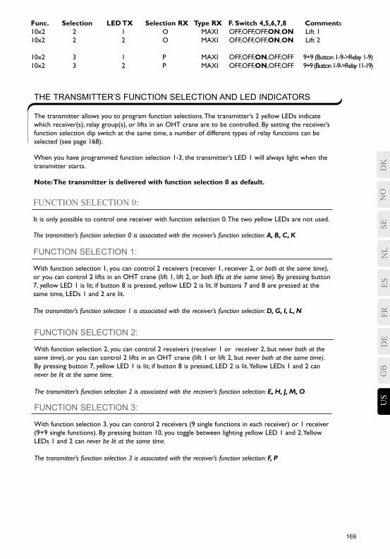
Func. Selection LED TX Selection RX Type RX F. Switch 4,5,6,7,8 Comments10x2 2 1 O MAXI OFF,OFF,OFF,ON,ON Lift 110x2 2 2 O MAXI OFF,OFF,OFF,ON,ON Lift 2
10x2 3 1 P MAXI OFF,OFF,ON,OFF,OFF 9+9 (Button 1-9->Relay 1-9)10x2 3 2 P MAXI OFF,OFF,ON,OFF,OFF 9+9 (Button 1-9->Relay 11-19)
THE TRANSMITTER’S FUNCTION SELECTION AND LED INDICATORS
The transmitter allows you to program function selections. The transmitter’s 2 yellow LEDs indicate which receiver(s), relay group(s), or lifts in an OHT crane are to be controlled. By setting the receiver’s function selection dip switch at the same time, a number of different types of relay functions can be selected (see page 168).
When you have programmed function selection 1-3, the transmitter’s LED 1 will always light when the transmitter starts.
Note: The transmitter is delivered with function selection 0 as default.
FUNCTION SELECTION 1:
With function selection 1, you can control 2 receivers (receiver 1, receiver 2, or both at the same time), or you can control 2 lifts in an OHT crane (lift 1, lift 2, or both lifts at the same time). By pressing button 7, yellow LED 1 is lit; if button 8 is pressed, yellow LED 2 is lit. If buttons 7 and 8 are pressed at the same time, LEDs 1 and 2 are lit.
The transmitter’s function selection 1 is associated with the receiver’s function selection: D, G, I, L, N
FUNCTION SELECTION 3:
With function selection 3, you can control 2 receivers (9 single functions in each receiver) or 1 receiver (9+9 single functions). By pressing button 10, you toggle between lighting yellow LED 1 and 2. Yellow LEDs 1 and 2 can never be lit at the same time.
The transmitter’s function selection 3 is associated with the receiver’s function selection: F, P
FUNCTION SELECTION 2:
With function selection 2, you can control 2 receivers (receiver 1 or receiver 2, but never both at the same time), or you can control 2 lifts in an OHT crane (lift 1 or lift 2, but never both at the same time). By pressing button 7, yellow LED 1 is lit; if button 8 is pressed, LED 2 is lit. Yellow LEDs 1 and 2 can never be lit at the same time.
The transmitter’s function selection 2 is associated with the receiver’s function selection: E, H, J, M, OSE
ESFR
DE
GB
US
NO
DK
NL
170 171
NO
DK
SENL
ESFR
DE
GB
US
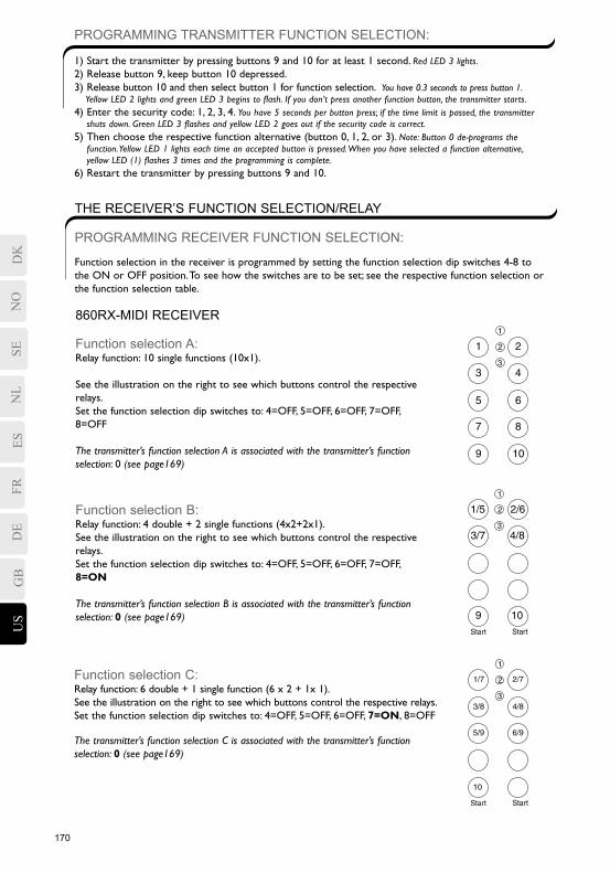
PROGRAMMING TRANSMITTER FUNCTION SELECTION:
1) Start the transmitter by pressing buttons 9 and 10 for at least 1 second. Red LED 3 lights.2) Release button 9, keep button 10 depressed.3) Release button 10 and then select button 1 for function selection. You have 0.3 seconds to press button 1. Yellow LED 2 lights and green LED 3 begins to flash. If you don’t press another function button, the transmitter starts.4) Enter the security code: 1, 2, 3, 4. You have 5 seconds per button press; if the time limit is passed, the transmitter shuts down. Green LED 3 flashes and yellow LED 2 goes out if the security code is correct.5) Then choose the respective function alternative (button 0, 1, 2, or 3). Note: Button 0 de-programs the function. Yellow LED 1 lights each time an accepted button is pressed. When you have selected a function alternative, yellow LED (1) flashes 3 times and the programming is complete.6) Restart the transmitter by pressing buttons 9 and 10.
THE RECEIVER’S FUNCTION SELECTION/RELAY
PROGRAMMING RECEIVER FUNCTION SELECTION:
Function selection in the receiver is programmed by setting the function selection dip switches 4-8 to the ON or OFF position. To see how the switches are to be set; see the respective function selection or the function selection table.
860RX-MIDI RECEIVER
Function selection A:Relay function: 10 single functions (10x1). See the illustration on the right to see which buttons control the respective relays.Set the function selection dip switches to: 4=OFF, 5=OFF, 6=OFF, 7=OFF, 8=OFF
The transmitter’s function selection A is associated with the transmitter’s function selection: 0 (see page169)
Function selection B:Relay function: 4 double + 2 single functions (4x2+2x1). See the illustration on the right to see which buttons control the respective relays.Set the function selection dip switches to: 4=OFF, 5=OFF, 6=OFF, 7=OFF, 8=ON
The transmitter’s function selection B is associated with the transmitter’s function selection: 0 (see page169)
Function selection C:Relay function: 6 double + 1 single function (6 x 2 + 1x 1). See the illustration on the right to see which buttons control the respective relays.Set the function selection dip switches to: 4=OFF, 5=OFF, 6=OFF, 7=ON, 8=OFF
The transmitter’s function selection C is associated with the transmitter’s function selection: 0 (see page169)
170 171
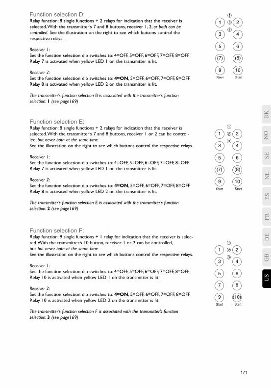
Function selection D:Relay function: 8 single functions + 2 relays for indication that the receiver is selected. With the transmitter’s 7 and 8 buttons, receiver 1, 2, or both can be controlled. See the illustration on the right to see which buttons control the respective relays.
Receiver 1:Set the function selection dip switches to: 4=OFF, 5=OFF, 6=OFF, 7=OFF, 8=OFFRelay 7 is activated when yellow LED 1 on the transmitter is lit.
Receiver 2: Set the function selection dip switches to: 4=ON, 5=OFF, 6=OFF, 7=OFF, 8=OFFRelay 8 is activated when yellow LED 2 on the transmitter is lit.
The transmitter’s function selection B is associated with the transmitter’s function selection: 1 (see page169)
Function selection E:Relay function: 8 single functions + 2 relays for indication that the receiver is selected. With the transmitter’s 7 and 8 buttons, receiver 1 or 2 can be control-led, but never both at the same time.See the illustration on the right to see which buttons control the respective relays.
Receiver 1:Set the function selection dip switches to: 4=OFF, 5=OFF, 6=OFF, 7=OFF, 8=OFFRelay 7 is activated when yellow LED 1 on the transmitter is lit.
Receiver 2: Set the function selection dip switches to: 4=ON, 5=OFF, 6=OFF, 7=OFF, 8=OFFRelay 8 is activated when yellow LED 2 on the transmitter is lit.
The transmitter’s function selection E is associated with the transmitter’s function selection: 2 (see page169)
Function selection F:Relay function: 9 single functions + 1 relay for indication that the receiver is selec-ted. With the transmitter’s 10 button, receiver 1 or 2 can be controlled, but but never both at the same time.See the illustration on the right to see which buttons control the respective relays.
Receiver 1:Set the function selection dip switches to: 4=OFF, 5=OFF, 6=OFF, 7=OFF, 8=OFFRelay 10 is activated when yellow LED 1 on the transmitter is lit.
Receiver 2: Set the function selection dip switches to: 4=ON, 5=OFF, 6=OFF, 7=OFF, 8=OFFRelay 10 is activated when yellow LED 2 on the transmitter is lit.
The transmitter’s function selection F is associated with the transmitter’s function selection: 3 (see page169)
SEES
FRDE
GB
US
NO
DK
NL
172 173
NO
DK
SENL
ESFR
DE
GB
US
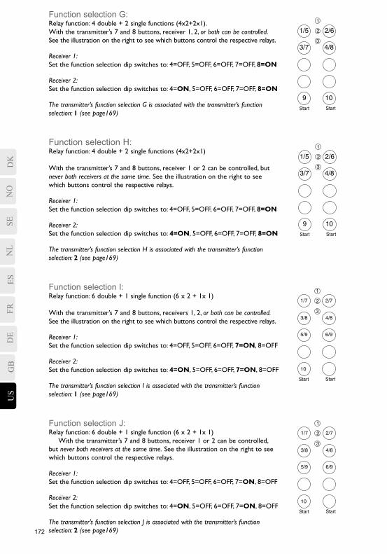
Function selection G:Relay function: 4 double + 2 single functions (4x2+2x1). With the transmitter’s 7 and 8 buttons, receiver 1, 2, or both can be controlled.See the illustration on the right to see which buttons control the respective relays.
Receiver 1:Set the function selection dip switches to: 4=OFF, 5=OFF, 6=OFF, 7=OFF, 8=ON
Receiver 2: Set the function selection dip switches to: 4=ON, 5=OFF, 6=OFF, 7=OFF, 8=ON
The transmitter’s function selection G is associated with the transmitter’s function selection: 1 (see page169)
Function selection H:Relay function: 4 double + 2 single functions (4x2+2x1)
With the transmitter’s 7 and 8 buttons, receiver 1 or 2 can be controlled, but never both receivers at the same time. See the illustration on the right to see which buttons control the respective relays.
Receiver 1:Set the function selection dip switches to: 4=OFF, 5=OFF, 6=OFF, 7=OFF, 8=ON
Receiver 2: Set the function selection dip switches to: 4=ON, 5=OFF, 6=OFF, 7=OFF, 8=ON
The transmitter’s function selection H is associated with the transmitter’s function selection: 2 (see page169)
Function selection I:Relay function: 6 double + 1 single function (6 x 2 + 1x 1) With the transmitter’s 7 and 8 buttons, receivers 1, 2, or both can be controlled.See the illustration on the right to see which buttons control the respective relays.
Receiver 1:Set the function selection dip switches to: 4=OFF, 5=OFF, 6=OFF, 7=ON, 8=OFF
Receiver 2: Set the function selection dip switches to: 4=ON, 5=OFF, 6=OFF, 7=ON, 8=OFF
The transmitter’s function selection I is associated with the transmitter’s function selection: 1 (see page169)
Function selection J:Relay function: 6 double + 1 single function (6 x 2 + 1x 1) With the transmitter’s 7 and 8 buttons, receiver 1 or 2 can be controlled, but never both receivers at the same time. See the illustration on the right to see which buttons control the respective relays.
Receiver 1:Set the function selection dip switches to: 4=OFF, 5=OFF, 6=OFF, 7=ON, 8=OFF
Receiver 2: Set the function selection dip switches to: 4=ON, 5=OFF, 6=OFF, 7=ON, 8=OFF
The transmitter’s function selection J is associated with the transmitter’s function selection: 2 (see page169)
172 173
860RX-MAXI RECEIVER
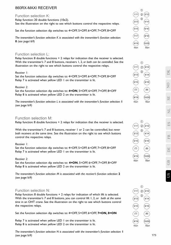
Function selection K:Relay function: 20 double functions (10x2). See the illustration on the right to see which buttons control the respective relays.
Set the function selection dip switches to: 4=OFF, 5=OFF, 6=OFF, 7=OFF, 8=OFF
The transmitter’s function selection K is associated with the transmitter’s function selection: 0 (see page169)
Function selection L:Relay function: 8 double functions + 2 relays for indication that the receiver is selected. With the transmitter’s 7 and 8 buttons, receivers 1, 2, or both can be controlled. See the illustration on the right to see which buttons control the respective relays.
Receiver 1:Set the function selection dip switches to: 4=OFF, 5=OFF, 6=OFF, 7=OFF, 8=OFFRelay 7 is activated when yellow LED 1 on the transmitter is lit.
Receiver 2: Set the function selection dip switches to: 4=ON, 5=OFF, 6=OFF, 7=OFF, 8=OFFRelay 8 is activated when yellow LED 2 on the transmitter is lit.
The transmitter’s function selection L is associated with the transmitter’s function selection: 1 (see page169)
Function selection M:Relay function: 8 double functions + 2 relays for indication that the receiver is selected.
With the transmitter’s 7 and 8 buttons, receiver 1 or 2 can be controlled, but never both receivers at the same time. See the illustration on the right to see which buttons control the respective relays.
Receiver 1:Set the function selection dip switches to: 4=OFF, 5=OFF, 6=OFF, 7=OFF, 8=OFFRelay 7 is activated when yellow LED 1 on the transmitter is lit.
Receiver 2: Set the function selection dip switches to: 4=ON, 5=OFF, 6=OFF, 7=OFF, 8=OFFRelay 8 is activated when yellow LED 2 on the transmitter is lit.
The transmitter’s function selection M is associated with the receiver’s function selection: 2 (see page169)
Function selection N:Relay function: 8 double functions + 2 relays for indication of which lift is selected. With the transmitter’s 7 and 8 buttons, you can control lift 1, 2, or both at the same time in an OHT crane. See the illustration on the right to see which buttons control the respective relays.
Set the function selection dip switches to: 4=OFF, 5=OFF, 6=OFF, 7=ON, 8=ON
Relay 7 is activated when yellow LED 1 on the transmitter is lit.Relay 8 is activated when yellow LED 2 on the transmitter is lit.
The transmitter’s function selection N is associated with the transmitter’s function selection: 1 (see page169)
SEES
FRDE
GB
US
NO
DK
NL
174 175
NO
DK
SENL
ESFR
DE
GB
US
MOMENTARY OR LATCHING RELAY FUNCTIONS
The system is delivered with the momentary function as its default setting. Program as described below if you wish to set a latching function. Momentary function = The relay actuates/is activated only during the time the transmitter button is pressed.
Latching/Toggle function = The relay’s position changes every time the button on the transmitter is pressed, but retains the new position after you release the button.
PROGRAMMING THE LATCHING RELAY FUNCTION: 1) Start the system.2) Set the receiver’s function selection dip switch 1 to the ON position. All relays in the receiver are disconnected and the red LEDs for the respective relays go out.3) Press the buttons on the transmitter that you wish to have a latching/toggle function. The red LED will light for the relays that you have selected to have latching/toggle functions.4) Set the receiver’s function selection dip switch 1 to the OFF position. Latching relay functions are programmed and can now be used.
RESTORE DEFAULT SETTINGS (MOMENTARY):1) Start the system.2) Set the receiver’s function selection dip switch 1 to the ON position. All relays in the receiver are disconnected and the red LEDs for the respective relays go out.3) Set the receiver’s function selection dip switch 1 to the OFF position. All relays have momentary functions.
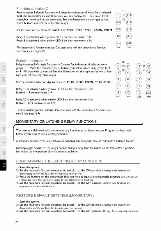
Function selection P:Relay function: 9+9 single functions + 2 relays for indication of selected relay group. With the transmitter’s 10 button, you select which relay group (1-9 or 11-19) you wish to control. See the illustration on the right to see which but-tons control the respective relays.
Set the function selection dip switches to: 4=OFF, 5=OFF, 6=ON, 7=OFF, 8=OFF
Relay 10 is activated when yellow LED 1 on the transmitter is lit.Buttons 1-9 control relays 1-9.
Relay 20 is activated when yellow LED 2 on the transmitter is lit.Buttons 11-19 control relays 1-9.
The transmitter’s function selection P is associated with the transmitter’s function selec-tion: 3 (see page169)
Function selection O:Relay function: 8 double functions + 2 relays for indication of which lift is selected. With the transmitter’s 7 and 8 buttons, you can control lift 1 or 2 in an OHT crane, but never both at the same time. See the illustration on the right to see which buttons control the respective relays.
Set the function selection dip switches to: 4=OFF, 5=OFF, 6=OFF, 7=ON, 8=ON
Relay 7 is activated when yellow LED 1 on the transmitter is lit.Relay 8 is activated when yellow LED 2 on the transmitter is lit.
The transmitter’s function selection O is associated with the transmitter’s function selection: 2 (see page169)
174 175
Setting pre-sets means that it is possible to pre-set/prioritize one relay function/button over another.If a pre-set is programmed and two buttons are pressed at the same time, the transmitter prioritizes/pre-sets one of the buttons over the other, which makes it impossible, for example, to activate the up and down buttons together.
Look through the options and decide which channel/frequency you want to program using the table below before you begin programming.
Note that the alternative OFF, OFF = no pre-set
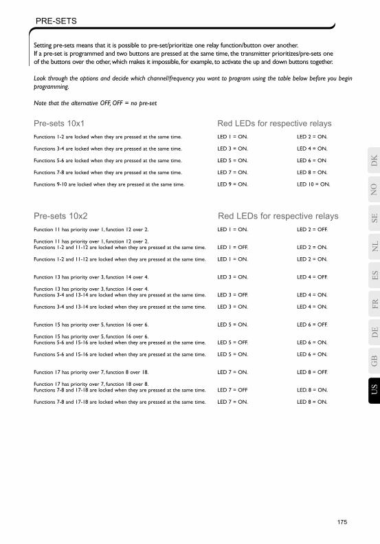
Pre-sets 10x1 Red LEDs for respective relays Functions 1-2 are locked when they are pressed at the same time. LED 1 = ON. LED 2 = ON.
Functions 3-4 are locked when they are pressed at the same time. LED 3 = ON. LED 4 = ON.
Functions 5-6 are locked when they are pressed at the same time. LED 5 = ON. LED 6 = ON
Functions 7-8 are locked when they are pressed at the same time. LED 7 = ON. LED 8 = ON.
Functions 9-10 are locked when they are pressed at the same time. LED 9 = ON. LED 10 = ON.
Pre-sets 10x2 Red LEDs for respective relays Function 11 has priority over 1, function 12 over 2. LED 1 = ON. LED 2 = OFF.
Function 11 has priority over 1, function 12 over 2. Functions 1-2 and 11-12 are locked when they are pressed at the same time. LED 1 = OFF. LED 2 = ON.
Functions 1-2 and 11-12 are locked when they are pressed at the same time. LED 1 = ON. LED 2 = ON.
Function 13 has priority over 3, function 14 over 4. LED 3 = ON. LED 4 = OFF.
Function 13 has priority over 3, function 14 over 4.Functions 3-4 and 13-14 are locked when they are pressed at the same time. LED 3 = OFF. LED 4 = ON.
Functions 3-4 and 13-14 are locked when they are pressed at the same time. LED 3 = ON. LED 4 = ON.
Function 15 has priority over 5, function 16 over 6. LED 5 = ON. LED 6 = OFF.
Function 15 has priority over 5, function 16 over 6.Functions 5-6 and 15-16 are locked when they are pressed at the same time. LED 5 = OFF. LED 6 = ON.
Functions 5-6 and 15-16 are locked when they are pressed at the same time. LED 5 = ON. LED 6 = ON.
Function 17 has priority over 7, function 8 over 18. LED 7 = ON. LED 8 = OFF.
Function 17 has priority over 7, function 18 over 8.Functions 7-8 and 17-18 are locked when they are pressed at the same time. LED 7 = OFF LED. 8 = ON.
Functions 7-8 and 17-18 are locked when they are pressed at the same time. LED 7 = ON. LED 8 = ON.
PRE-SETS
SEES
FRDE
GB
US
NO
DK
NL
176 177
NO
DK
SENL
ESFR
DE
GB
US
PROGRAMMING PRE-SETS:1) Start the system.2) On the receiver: set switch 3 of the function selection dip switch to the ON position. All relays in the receiver are disconnected and the red LEDs for the respective relays go out.3) On the transmitter: program by pressing the buttons (LEDs) that are marked ON in the table; pre-set. Ex. LED 5 = OFF and LED 6=ON, program by pressing button 6 on the transmitter, and the LEDs will then be lit as specified for the desired pre-set alternative. The red LED will light for the relays that you selected.4) On the receiver: set switch 3 to the OFF position. The pre-set is now complete and will be applied.
DELETING PRE-SETS:1) Start the system.2) On the receiver: set switch 3 of the function selection dip switch to the ON position. All relays in the receiver are disconnected and the red LEDs for the respective relays go out.3) On the receiver: set switch 3 of the function selection dip switch to the OFF position. The pre-set is now deleted (no relay is pre-set).
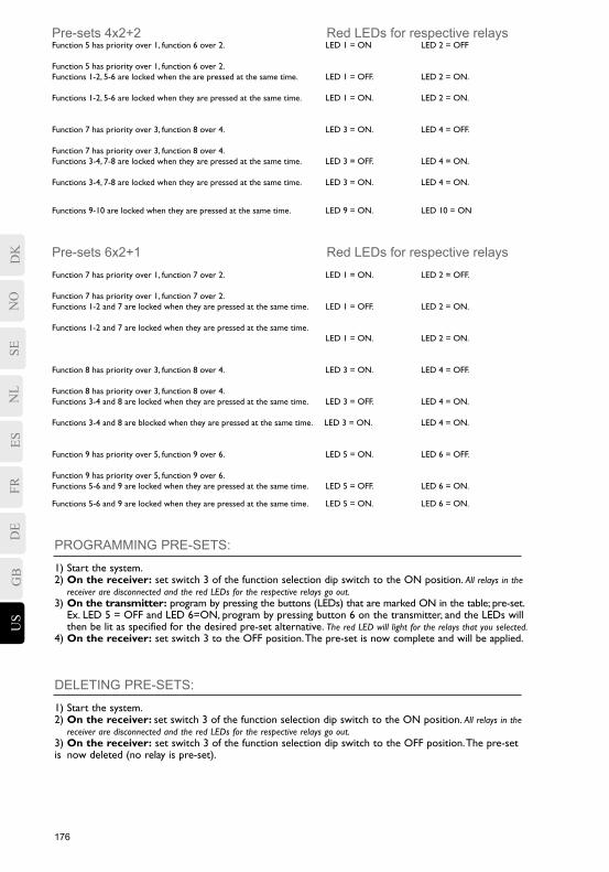
Pre-sets 4x2+2 Red LEDs for respective relaysFunction 5 has priority over 1, function 6 over 2. LED 1 = ON LED 2 = OFF
Function 5 has priority over 1, function 6 over 2.Functions 1-2, 5-6 are locked when the are pressed at the same time. LED 1 = OFF. LED 2 = ON.
Functions 1-2, 5-6 are locked when they are pressed at the same time. LED 1 = ON. LED 2 = ON.
Function 7 has priority over 3, function 8 over 4. LED 3 = ON. LED 4 = OFF. Function 7 has priority over 3, function 8 over 4.Functions 3-4, 7-8 are locked when they are pressed at the same time. LED 3 = OFF. LED 4 = ON.
Functions 3-4, 7-8 are locked when they are pressed at the same time. LED 3 = ON. LED 4 = ON.
Functions 9-10 are locked when they are pressed at the same time. LED 9 = ON. LED 10 = ON
Pre-sets 6x2+1 Red LEDs for respective relaysFunction 7 has priority over 1, function 7 over 2. LED 1 = ON. LED 2 = OFF.
Function 7 has priority over 1, function 7 over 2.Functions 1-2 and 7 are locked when they are pressed at the same time. LED 1 = OFF. LED 2 = ON.
Functions 1-2 and 7 are locked when they are pressed at the same time. LED 1 = ON. LED 2 = ON.
Function 8 has priority over 3, function 8 over 4. LED 3 = ON. LED 4 = OFF.
Function 8 has priority over 3, function 8 over 4.Functions 3-4 and 8 are locked when they are pressed at the same time. LED 3 = OFF. LED 4 = ON.
Functions 3-4 and 8 are blocked when they are pressed at the same time. LED 3 = ON. LED 4 = ON.
Function 9 has priority over 5, function 9 over 6. LED 5 = ON. LED 6 = OFF.
Function 9 has priority over 5, function 9 over 6.Functions 5-6 and 9 are locked when they are pressed at the same time. LED 5 = OFF. LED 6 = ON.
Functions 5-6 and 9 are locked when they are pressed at the same time. LED 5 = ON. LED 6 = ON.
176 177
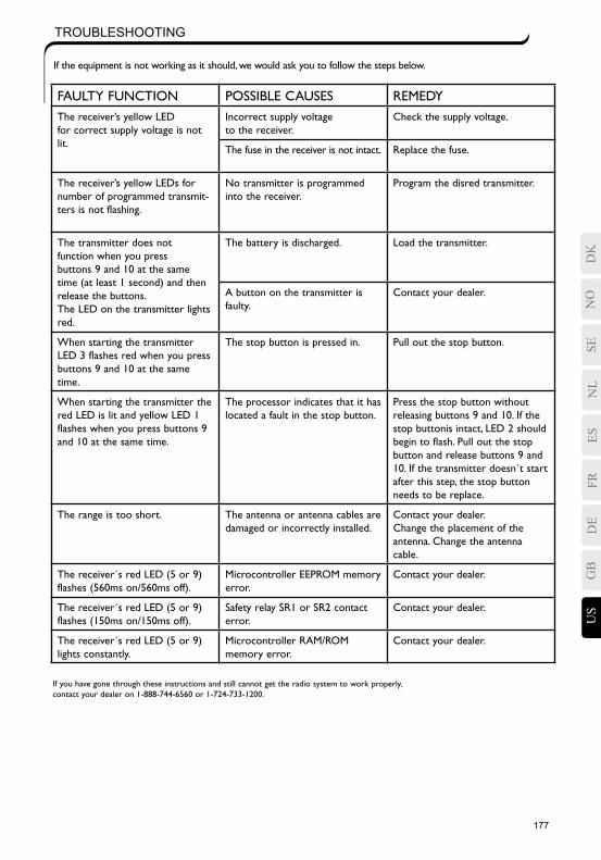
TROUBLESHOOTING
If the equipment is not working as it should, we would ask you to follow the steps below.
FAULTY FUNCTION POSSIBLE CAUSES REMEDYThe receiver’s yellow LED for correct supply voltage is not lit.
Incorrect supply voltage to the receiver.
Check the supply voltage.
The fuse in the receiver is not intact. Replace the fuse.
The receiver’s yellow LEDs for number of programmed transmit-ters is not flashing.
No transmitter is programmed into the receiver.
Program the disred transmitter.
The transmitter does not function when you press buttons 9 and 10 at the same time (at least 1 second) and then release the buttons.The LED on the transmitter lights red.
The battery is discharged. Load the transmitter.
A button on the transmitter is faulty.
Contact your dealer.
When starting the transmitter LED 3 flashes red when you press buttons 9 and 10 at the same time.
The stop button is pressed in. Pull out the stop button.
When starting the transmitter the red LED is lit and yellow LED 1 flashes when you press buttons 9 and 10 at the same time.
The processor indicates that it has located a fault in the stop button.
Press the stop button without releasing buttons 9 and 10. If the stop buttonis intact, LED 2 should begin to flash. Pull out the stop button and release buttons 9 and 10. If the transmitter doesn´t start after this step, the stop button needs to be replace.
The range is too short. The antenna or antenna cables are damaged or incorrectly installed.
Contact your dealer. Change the placement of the antenna. Change the antenna cable.
The receiver´s red LED (5 or 9) flashes (560ms on/560ms off).
Microcontroller EEPROM memory error.
Contact your dealer.
The receiver´s red LED (5 or 9) flashes (150ms on/150ms off).
Safety relay SR1 or SR2 contact error.
Contact your dealer.
The receiver´s red LED (5 or 9) lights constantly.
Microcontroller RAM/ROM memory error.
Contact your dealer.
If you have gone through these instructions and still cannot get the radio system to work properly, contact your dealer on 1-888-744-6560 or 1-724-733-1200.
SEES
FRDE
GB
US
NO
DK
NL
178 179
NO
DK
SENL
ESFR
DE
GB
US
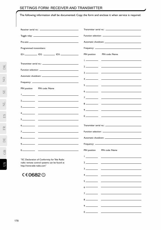
Transmitter serial no.:
Function selection:
Automatic shutdown:
Frequency:
PIN position PIN code /Name
1
2
3
4
5
6
7
8
9
0
Transmitter serial no.:
Function selection:
Automatic shutdown:
Frequency:
PIN position PIN code /Name
1
2
3
4
5
6
7
8
9
0
Receiver serial no.:
Toggle relay:
Pre-sets:
Programmed transmitters:
ID1: ID2: ID3:
Transmitter serial no.:
Function selection:
Automatic shutdown:
Frequency:
PIN position PIN code /Name
1
2
3
4
5
6
7
8
9
0
”EC Declaration of Conformity for Tele Radio radio remote control systems can be found at http://www.tele-radio.com”
SETTINGS FORM: RECEIVER AND TRANSMITTER
The following information shall be documented. Copy the form and enclose it when service is required.
178 179
TELERADIO COMPANY TERMS AND CONDITIONS OF SALE
1. AGREEMENT: The Purchaser grants to TeleRadio and TeleRadio retains a security interest in all equipment shipped pursuant to this contract and the proceeds thereof until the Purchaser shall have made full payment for the equipment. In the event of a failure to make payment on the date when due in accordance with the terms designated, the entire balance shall become due and payable at once. In case of default of payment, TeleRadio shall have the right to enter the premises of purchaser and take possession of the equipment immediately, wherever it may be found, and remove it with or without process of law and may retain all money paid hereunder as liquidated damages and rental for said equipment. While any amounts are payable to TeleRadio, the Purchaser shall not sell, mortgage, pledge or lease said TeleRadio equipment without the prior written permission of TeleRadio.
2. WARRANTIES: Subject to the limitations below, TeleRadio warrants all of its products to be free from material defects in material and workmanship. However, TeleRadio’s liability under such warranty shall be limited to repair or replacement of any product which TeleRadio’s inspection shall disclose to have been defective. This warranty does not apply to any products, which have been subject to abuse, mishandling, or improper use, and does not include field labor of any type. TeleRadio’s quo-tation does not include price provision for performance bond of indemnity. Therefore, the additional cost incurred to provide such a bond shall be added to the total amount of this quote and paid by Purchaser. The warranty period for any equipment shipped hereunder is one (1) year and covers all labor and material manufactured by TeleRadio, provided Purchaser returns them to the factory for repair. Defective items will be repaired or replaced free of charge at TeleRadio’s discretion, during the one- (1) year term of this warranty. Freight and/or postage are not covered by said warranty and will be paid by Purchaser. Any services rendered in the field will be performed at current rates for time and travel at the discretion of TeleRadio and will be paid by the Purchaser. All commercial grade products of TeleRadio carry a warranty period of one (1) year. Batteries, cases, switches, and such other items subject to normal wear and deterioration are not included in this warranty.TeleRadio’s warranty period begins at system receipt after direct shipment to the Purchaser.
IN NO EVENT WILL TELERADIO BE LIABLE FOR INDIRECT, SPECIAL, INCIDENTAL OR CONSEQUENTIAL DAMAGES.EXCEPT AS STATED ABOVE, TELERADIO MAKES NO REPRESENTATIONS OR WARRANTIES, EXPRESSED OR IMPLIED, NO OTHER REPRESENTATION OR WARRANTY IS GIVEN, AND NO AFFIRMATION OF TELERADIO OR ITS REPRESENTATIVES BY WORD OR ACTION SHALL CONSTITUTE A WARRANTY. THERE ARE NO WARRANTIES WHICH EXTEND BEYOND THE ONE (1) YEAR PERIOD DESCRIBED HEREIN. TELERADIO SPECIFICALLY DISCLAIMS, AND PURCHASER HEREBY WAIVES, ANY WARRANTIES OF MERCHANTABILITY OR FITNESS FOR PARTICULAR PURPOSE.
3. PAYMENT: In the event credit is applied for and granted, terms shall be net thirty (30) days. All equipment will be invoiced at time of shipment. In the event any payment is not received according to the terms set forth herein, TeleRadio may, at its discretion, assess interest at the rate of 1 and 1/2 percent per month or the maximum rate allowed by law. The Purchaser also agrees to pay any reasonable and customary legal fees or agency commissions sustained by TeleRadio in pursuit of any payment which is past due.
4. TAXES: The Purchaser agrees to pay any federal excise, state or local taxes, if any.
5. PRODUCT OR PRICE CHANGE: The contract, product specification, and statements concerning products and any publis-hed prices are subject to change without prior notification. The only exceptions are special quotations and purchase orders accepted by TeleRadio.
6. DELIVERY & LIABILITY: TeleRadio shall not be liable for loss or damage of any kind resulting from carrier delay, or inability to deliver on account of Acts of God, fire, labor troubles, accidents, acts of civil or military authorities, fuel, labor or material shortages, or other such conditions beyond TeleRadio’s control. The promised delivery date is the best estimate possible based on current and anticipated factory load. All shipments are made F.O.B. factory dock unless otherwise stated. All trans-portation, when not specified by Purchaser, will be the least expensive surface transportation. Costs of packing for domestic shipment are included in the quoted price. Any special packing may result in additional charges to Purchaser.
7. RETURNS & CANCELLATIONS: Orders placed by Purchaser, and entered upon TeleRadio’s books cannot be canceled or changed except with TeleRadio’s consent and upon terms that will indemnify TeleRadio against all losses. TeleRadio shall not accept returns without a request and authorization issued by it before shipment. All return shipments must be prepaid by the Purchaser and properly packed. TeleRadio shall not be responsible for damages incurred during such shipment.
8. GENERAL: All orders are subject to factory acceptance and shall not be considered a contract unless such order is accep-ted in writing by an authorized executive of Teleradio. Teleradio reserves the right to correct any clerical errors which may occur in quotations. Teleradio shall not be bound by any statements or promises made by any representative of TeleRadio which are not stated in and made a part of this contract. This contract is expressly made subject to the terms and conditions contained herein and will be interpreted accordingly if a conflict arises with Purchaser or its terms of purchase. The parties stipulate to the venue and jurisdiction of the courts located in Allegheny County, Pennsylvania for the resolution of any dispute that may arise hereunder.
TeleRadio Company, 1006 Corporate Lane, Unit C, Murry Corporate Park, Export, PA 15632
SEES
FRDE
GB
US
NO
DK
NL
180
NO
DK
SENL
ESFR
DE
GB
US
APPENDIX
15.19 - TWO PART WARNING STATEMENTTHIS DEVICE COMPLIES WITH PART 15 OF THE FCC RULES. OPERATION IS SUBJECT TO THE FOLLO-WING TWO CONDITIONS: (1) THIS DEVICE MAY NOT CAUSE HARMFUL INTERFERENCE, AND (2) THIS DEVICE MUST ACCEPT ANY INTERFERENCE RECEIVED, INCLUDING INTERFERENCE THAT MAY CAUSE UNDESIRED OPERATION.
15.21 - MODIFICATION STATEMENTNOTE: THE MANUFACTURER IS NOT RESPONSIBLE FOR ANY RADIO OR TV INTERFERENCE CAUSED BY UNAUTHORIZED MODIFICATIONS TO THIS EQUIPMENT. SUCH MODIFICATIONS COULD VOID THE USER´S AUTHORITY TO OPERATE THE EQUIPMENT.