Embed Size (px)
Citation preview

Connect - Contact - Control
1
InhaltRundsteckverbinder für Spezialanwendungen, Baureihe SB 2
Besondere Merkmale 2
Applikationen 2
Baureihenübersicht 2
Kompetenz 2
Normen 2
Technische Daten 3
Bestellschlüssel 4
5-polig + PE Flanschstecker, Kabeldose 4
6-polig Flanschdose, Kabelstecker 5
14-polig Flanschstecker, Kabeldose 5
Montage 6
Werkzeuge Ausdrückwerkzeuge AWZ-A und AWZ-C/H, Crimpzange CWZ-600 6
Montagebohrungen 6
Kontakte Stecker: Crimpkontakte, Dosen: Lötkontakte 7
Deratingkurven 7
Sicherheitshinweise 7
LV-HPC Series
High Power Connectors for industrial trucks
Crimping, Installation and Maintenance Instructions
Manual A84-M.en
Connectors
Instructions for the LV series 2015-06-16 Page 2
Document Revision History:
Date : Version Reason for change Pages: Name
2014-06-30 01 First edition all M. Heim
2015-06-16 02 W-crimping with support
New crimping pliers CWZ-600-1
Add slider LV320/400 version
15
17
19 ff
M.Heim
Contents
Important fundamental information ................................................................. 4
Conventions for these instructions ................................................................. 4
Adherence to the instructions .......................................................................... 6
General and safety information ........................................................................ 7
Liabilities of the OEM, operating company and/or the maintenance staff ........ 7
Intended use ...................................................................................................... 7
Ambient conditions.......................................................................................... 7
Misuse ................................................................................................................ 7
Residual risks and safety measures ................................................................ 8
Electrical hazards............................................................................................ 8
Mechanical hazards ........................................................................................ 8
Other hazards ................................................................................................ 9
Description ........................................................................................................ 9
Label ............................................................................................................... 9
Technical data ................................................................................................. 10
Crimping instructions ..................................................................................... 12
Stripping ....................................................................................................... 12
Crimping and identification ............................................................................ 13
Heat-shrink sleeve .................................................................................... 13
Crimp quality ................................................................................................... 14
Transition resistances between the crimping sleeve and the cable .............. 14
Compression ................................................................................................. 14
Pull-out forces as per DIN EN 61238-1 ......................................................... 14
Crimping instructions for main contacts ......................................................... 15
Crimping pliers for main contacts ............................................................. 16

Instructions for the LV series 2015-06-16 Page 3
Crimping instructions for pilot and auxiliary contacts ..................................... 17
Crimping pliers for pilot and auxiliary contacts .......................................... 17
Installation instructions .................................................................................. 18
Installation of main contacts .......................................................................... 18
Dismantling the main contacts ...................................................................... 24
Installing the pilot and auxiliary contacts ....................................................... 25
Dismantling the pilot and auxiliary contacts ................................................... 26
Extraction tools for pilot and auxiliary contacts ......................................... 26
Installing the air tube adapter ........................................................................ 28
EUW - Electrolyte circulation .................................................................... 29
Dismantling the pilot and air tube adapters ................................................... 29
Installing the handles of different models ...................................................... 31
Maintenance..................................................................................................... 31
Plugging the device and charging connectors .......................................... 32
Main contacts ........................................................................................... 32
Pin and socket housings ........................................................................... 36
Slider ........................................................................................................ 36
Heat-shrink sleeves .................................................................................. 38
Strain relief ............................................................................................... 38
Handle LV (snap-on, screw-in) ................................................................. 39
Pilot contact adapter ................................................................................. 39
Pilot and auxiliary contacts (pin, socket) ................................................... 39
Electrolyte circulation ............................................................................... 40
Keying plug .............................................................................................. 40
Cables ...................................................................................................... 41
Maintenance points ....................................................................................... 41
Ordering the spare parts ............................................................................... 43
Bibliography .................................................................................................... 43
List of spare parts ........................................................................................... 44
Instructions for the LV series 2015-06-16 Page 4
Fundamental conditions
1. Device and charging connectors may be inserted or disconnected only under load-free conditions. This means that the charger must be switched off before inserting or disconnecting to ensure that current is not flowing.
2. Device and charging connectors may be used only if they have been properly installed and are intact.
3. Device and charging connectors may be inserted or disconnected only manually. Other aids that increase the actuation forces (e.g. hammers, levers and screwdrivers) are not allowed.
4. Device and charging connectors may be operated only if they have been completely inserted. Device and charging connectors that can be inserted only with increased forces must be replaced.
5. Keep the device and charging connectors clean and, if required, clean them using compressed air. Contaminations may lead to leakage currents and increased insertion forces.
Legal instructions
Without explicit approval of SCHALTBAU GmbH, the manual may not be, fully or in parts, duplicated electronically or mechanically, distributed, modified, forwarded, translated into other languages or used in any other manner.
SCHALTBAU GmbH is not liable for damages if crimping, installation and maintenance instructions are not followed or followed only partially, if original SCHALTBAU GmbH spare parts are not used or if modified parts are used.
The following symbols are used in this manual to indicate instructions with special significance.
DANGER
This indicates an imminent dangerous situation. If such a situation is not avoided, it may lead to death or severe injuries.
Important fundamental information
Conventions for these instructions

Instructions for the LV series 2015-06-16 Page 5
WARNING
This indicates a potentially dangerous situation. If such a situation is not avoided, it may lead to death or severe injuries.
CAUTION
This indicates a potentially dangerous situation. If such a situation is not avoided, it may lead to minor or moderate injuries.
ATTENTION
This indicates a potentially hazardous situation. If such a situation is not avoided, assemblies, system or objects in its surroundings may get damaged.
NOTE refers to technical features and methods that are executed correctly.
Warning against hazardous electric potential
NOTE refers to technical features and methods that facilitate work or provide information that is of special significance.
NOTE refers to technical features and methods that are not executed in the correct type and manner.

Instructions for the LV series 2015-06-16 Page 6
Device and charging connectors described here are used in industrial trucks with battery-electrical operation or similar battery-electrical applications.
DANGER
Always follow these instructions for the crimping, installation and maintenance of device and charging connectors without fail.
Only experts with adequate technical knowledge may plan and execute the mechanical and electrical installations, transport, set-up and commissioning activities and initiate maintenance and repair measures. This is applicable to the adherence of general set-up and safety regulations for working on high-voltage systems (e.g. DIN, VDE), as well as for the proper usage of approved tools and personal protective equipment. Device connectors must be protected from moisture and dust during installation, operation or storage.
In case of doubts, we recommend that you contact SCHALTBAU GmbH or the industrial truck manufacturer to get support for the installation, commissioning and all the service activities.
Adherence to the instructions
Figures and photos are only for the purpose of orientation. Differences between individual device and charging connectors, between the pin and the socket sides as well as different series are not shown.

Instructions for the LV series 2015-06-16 Page 7
Crimping, installation and maintenance instructions must be read, understood and followed when carrying out all activities.
Read all the safety instructions and follow them with utmost care at all times.
Follow all the prevailing national regulations, all safety, accident prevention and environment protection regulations as well as the recognised technological rules for safe and proper operation.
Check all the existing protective and safety devices regularly for proper functioning.
Only a qualified electrician or a trained person may work on the electrical devices under the guidance and supervision of an experienced qualified electrician in accordance with the electro-technical regulations.
An expert is a person who can assess and execute essential activities and identify possible dangers based on his/her technical education, knowledge, experience and awareness about the prevalent regulations.
Operate the device and charging connectors of the LV series only under the ambient conditions specified in the following technical data.
Repair activities other than those mentioned in this crimping, installation and maintenance manual carried out by untrained personnel.
The connector of the LV series may not be altered or modified; else, the manufacturer’s liability shall become void.
The device and charging connectors may not be operated without rectifying the faults shown by the system or faults determined using any other method as well as defects such as the coding, or without the intended keying plug.
The connector may not be used outside the usage conditions defined for the intended usage, such as voltage, current intensity, ambient conditions, etc.
Inserting or disconnecting the connector using hammers and/or levers and/or screwdrivers or other aids is not permissible.
Device and charging connectors may not be poured over with or contaminated with electrolyte liquids or other liquids.
Operating the connector with damaged main contacts, e.g. after an emergency actuation or after inserting and disconnecting under load, is not permissible.
Never pull or press the cables for inserting or pulling out the connectors, even when a handle is not provided. Directly hold the housing if there is no handle.
General and safety information
Liabilities of the OEM, operating company and/or the
maintenance staff
Intended use
Ambient conditions
Misuse
Instructions for the LV series 2015-06-16 Page 8
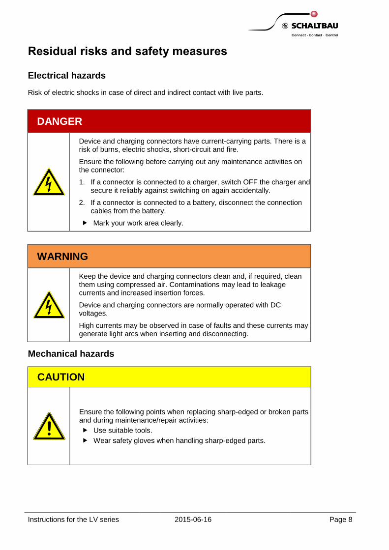
Risk of electric shocks in case of direct and indirect contact with live parts.
Residual risks and safety measures
Electrical hazards
DANGER
Device and charging connectors have current-carrying parts. There is a risk of burns, electric shocks, short-circuit and fire.
Ensure the following before carrying out any maintenance activities on the connector:
1. If a connector is connected to a charger, switch OFF the charger and secure it reliably against switching on again accidentally.
2. If a connector is connected to a battery, disconnect the connection cables from the battery.
Mark your work area clearly.
WARNING
Keep the device and charging connectors clean and, if required, clean them using compressed air. Contaminations may lead to leakage currents and increased insertion forces.
Device and charging connectors are normally operated with DC voltages.
High currents may be observed in case of faults and these currents may generate light arcs when inserting and disconnecting.
Mechanical hazards
CAUTION
Ensure the following points when replacing sharp-edged or broken parts and during maintenance/repair activities:
Use suitable tools.
Wear safety gloves when handling sharp-edged parts.
Instructions for the LV series 2015-06-16 Page 9
Other hazards
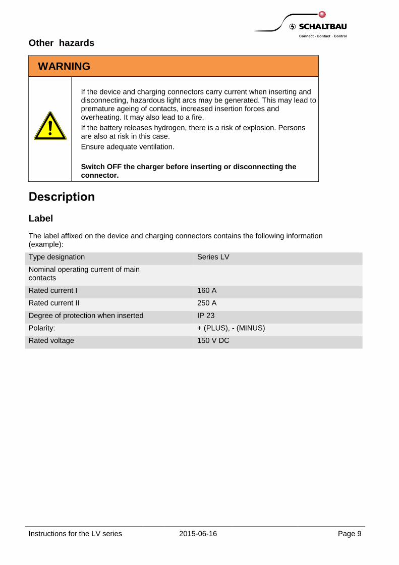
The label affixed on the device and charging connectors contains the following information (example):
Type designation Series LV
Nominal operating current of main contacts
Rated current I 160 A
Rated current II 250 A
Degree of protection when inserted IP 23
Polarity: + (PLUS), - (MINUS)
Rated voltage 150 V DC
WARNING
If the device and charging connectors carry current when inserting and disconnecting, hazardous light arcs may be generated. This may lead to premature ageing of contacts, increased insertion forces and overheating. It may also lead to a fire.
If the battery releases hydrogen, there is a risk of explosion. Persons are also at risk in this case.
Ensure adequate ventilation.
Switch OFF the charger before inserting or disconnecting the connector.
Description
Label

Instructions for the LV series 2015-06-16 Page 10
The latest version of technical data can be downloaded from www.schaltbau-gmbh.com/de/Download/.
Series Standard LV320/400 LV160/250 LV80/120
Nominal operating current *1
Main contacts
Pilot contacts
DIN VDE 0623-589
320 A / 400 A*1
20 A
160 A / 250 A*1
20 A
80 A / 120 A*1
20 A
Rated voltage DIN VDE 0623-589 150 V 150 V 150 V
Code
Nominal operating voltages
Keying plug
DIN VDE 0623-589
24 / 36 / 48 / 72 / 80 / 96 V
Red*1/grey: Wet-cell battery, green: Dry-cell battery, yellow: Vehicle plug
Main contacts
Number
Contact diameter
Wire gauge
16 mm²
25 mm²
35 mm²
50 mm²
70 mm²
95 mm²
DIN VDE 0623-589
2
10 mm
---
---
+ LV RH 50/35*2
*1
2
8.5 mm
---
+ LV RH 50/25*2
+ LV RH 50/35*2
*1
---
---
2
6 mm
+ LV RH 25/16*2+ *
1
*1
---
---
---
---
Pilot contacts
Number
Contact diameter
Wire gauge 2.5 mm²
DIN VDE 0623-589
2
4 mm
2
4 mm
2
2.3 mm
Auxiliary contacts
Number
Contact diameter
Wire gauge 2.5 mm
DIN VDE 0623-589
2
4 mm
2
4 mm
2
2.3 mm
Air tube adapter
Hose connection 6 mm
Hose connection 9 to 10 mm
DIN VDE 0623-589
*5
*5
*5
Crimp connection
Main contacts
Pilot contacts
W-crimping
W-crimping
W-crimping
W-crimping
W-crimping
W-crimping
Degree of protection EN1175-1 IP23*3 IP23*
3 IP23*
3
Temperature range -30 °C to +110 °C*4 -30 °C to +110 °C*
4 -30 °C to +110 °C*
4
Number of connection cycles EN1175-1 > 5000 > 5000 > 5000
Housing
PBT GF30 (free from PBB and
PBDE) integrated interlock
Strain relief
Burning behaviour
UL94
V0
V0
V0
Handle, variants
Snap-on
Screw-in
Handle, colour
Black
Red (emergency-stop identification)
Approvals
* 1 For 400 A, 250 A and 120 A, use the corresponding red keying plug and follow the wire gauges as indicated by the DIN VDE 0623-589 standard. Please take into account the dependency of the nominal operating current on the wire gauge; see (LV320/400), (LV160/250) and (LV80/120)
* 2 Main contact with reducer: Reduction from the wire gauge of the main contact to the wire gauge of the cable
* 3 IPx3 in horizontal installation position
* 4 Please follow the current carrying capacity curves, (LV320/400), (LV160/250) and (LV80/120)
* 5 With an adapter, see below “Adapters for air tube adapter”
Technical data

Instructions for the LV series 2015-06-16 Page 11
Adapter Ordering code Figure Ordering code Figure
Adapter for 6 mm air tubes with wall thickness > 1.5 mm
LV80/160/320 V-S 6/6
Adapter from 6 mm to 9..10 mm
LV80/160/320 V-S 6/10
LV320/400
Main contacts, aux. contacts
LV160/250
Main contacts, aux. contacts
LV80/120
Main contacts, aux. contacts
* High Power Connector, to be used with the red keying plug
Extra air tube adapters
Do you need an adapter for air tubes with greater diameters or deviating wall thickness?
Adapters are available for adapting air tubes with the following inside diameters:
Inside diameter Ø 9 to 10 mm Inside diameter Ø 6 mm and wall thickness > 1.5 mm.

Instructions for the LV series 2015-06-16 Page 12
DANGER
Always follow these instructions for crimping the cables without fail.
Main contacts Cable cross-section mm
2 Dimension L mm (+1)
LV80 LV80 P6/10 10
18 LV80 P6/25 with LV RH-25/16 16
LV80 P6/25 25
LV80 S6/25 with LV RH-25/16 16
LV80 S6/25 25
LV160 LV160 P8.5/50 with LV RH-50/25 25
20
LV160 P8.5/50 with LV RH-50/35 35
LV160 P8.5/50 50
LV160 S8.5/50 with LV RH-50/25 25
LV160 S8.5/50 with LV RH-50/35 35
LV160 S8.5/50 50
LV320 LV320 P10/50 with LV RH-50/35 35 20 LV320 P10/50 50
LV320 P10/70 70
LV320 P10/95 95 25
LV320 S10/50 with LV RH-50/35 35 20 LV320 S10/50 50
LV320 S10/70 70
LV320 S10/95 95 25
Contacts Designation Cable cross-
section mm2
Dimension L mm (±0.5)
LV80 Pilot and auxiliary contacts LV80 SBC-2.50-Ag pin
2.5
7.5
LV80 BBC-2.50-Ag socket
LV160
Pilot contacts SCC-2.50-Ag pin
BCC-2.50-Ag socket
Auxiliary contacts LV160 SBC-2.50-Ag pin
LV160 BBC-2.50-Ag socket
LV320
Pilot contacts SCC-2.50-Ag pin
BCC-2.50-Ag socket
Auxiliary contacts LV320 SCC-2.50-Ag pin
LV320 BCC-2.50-Ag socket
Crimping instructions
Stripping

Instructions for the LV series 2015-06-16 Page 13
Dimensions for crimping Position and dimensions for the heat-shrink sleeve
CAUTION
To ensure that the slider can latch flawlessly, maintain a distance of at least 10 mm between the heat-shrink sleeve and the collar of the contact.
Heat-shrink sleeve
Schaltbau GmbH recommends the use of a flexible, flame-resistant and/or self-extinguishing heat-shrink sleeve based on polyolefin with excellent resistance to acids and alkalis. Temperature range -40 °C to +135 °C
Minimum shrink temperature
+95 C
Test Test procedures Requirement
Dielectric strength IEC 243 and/or IEC 685 P2
20 MV/m
Fire protection properties
Flame-resistant and/or self-extinguishing
Heat-shrink sleeve, shrink rate 2:1
Ø Delivery dimension, minimum D [mm] 19
Ø after complete shrinkage, maximum d [mm] 9.5
Wall thickness WT [mm] 0.8
Crimping and identification

Instructions for the LV series 2015-06-16 Page 14
Cable cross-section mm2 Transition resistance (µΩ)
(Empirical values in new condition)
10 80-90
16 50-60
25 20-40
35 10-30
50 10-20
70 Up to 15
95 Up to 15
Measurement points for the transition resistance
Correct W-crimping is identified by uniformly deformed individual cores
Hexagon crimping with defective compression, individual cores are not deformed in some cases
Tensile stress for cable material - copper: 60 x cable cross-section
Cable cross-section mm2
Pull-out force (N)
10 600
16 960
25 1500
35 2100
50 3000
70 4200
95 5700
Crimp quality
Transition resistances between the crimping sleeve and the cable
Compression
Pull-out forces as per DIN EN 61238-1
No hollow spaces, good core compression

Instructions for the LV series 2015-06-16 Page 15
General information DIN EN 60352-2 – Solderless electrical connections, crimped connections is binding for the crimping of main contacts.
ATTENTION
Adhere to the following points to ensure that the crimped connections are functional at all times:
1. Do not solder stranded wires before crimping.
2. Do not solder a crimped connection after crimping.
Transition resistance In case of a proper W-crimping, the transition resistance at the crimping point in a new cable must be in the range from 10 to 90 μΩ, depending on the cable cross-section (see the table crimping quality – transition resistances). Usable cables Use rubber-insulated cables (arc welding cables as per DIN VDE 0282-6), e.g. H01N2-D. Cables deviating from this must be validated by the OEM/operating company for the respective application. Temperature range, derating curves The temperate range of H01N2-D cables is from -40 °C to + 110 °C taking into account the current-carrying capacity curves (base curves) and the corrected current-carrying capacity curves in the continuous operation range and the derating curves (as per DIN EN 60512-5-2, test 5b). The derating curve with the correction factor 0.8 x In(base curve) is therefore applicable for currents that are supposed to flow continuously and not intermittently, through the main contacts of the device and charging connectors at a simultaneous current load of a maximum of 20 A of pilot contacts without exceeding the upper permissible limit temperature of H01N2-D cable of + 110 °C. Procedure for crimping the main contacts
ATTENTION
SCHALTBAU GmbH requires W-crimping of main contacts. Only the W-crimping with proper deformation of individual cores ensures a gas-tight
connection. The deformation of crimping sleeve and individual cores result in a structure that is insulated (cold weld) by oxygen and is therefore adequately protected from internal corrosion over a long time.
The W-crimping leads to low oxidation during operation and ensures permanent low transition resistances as the basis for low intrinsic heating of crimping points in case of high currents.
When w-crimping the main contacts make sure that the contacts do not become bent out of shape. To this end provide some kind of support for that part of the contact extending beyond the anvil. Make sure it rests firmly on the supporting surface.
All electrical parameters specified by SCHALTBAU GmbH are based on measurements with contacts that were made using the W-crimping.
Crimping instructions for main contacts

Instructions for the LV series 2015-06-16 Page 16
Determining the press clamp size
SCHALTBAU GmbH recommends using the WHPH 10 crimping tool in case of large quantities of hydraulic heads WHK 8S, WHK 8 or WHK 9 of Stocko or comparable devices of other manufacturers. Refer to the following table for the correct pressing clamp size.
Crimping pliers for main contacts
Stocko WHPH 10 or for larger quantities Hydraulic heads WHK 8S, WHK 8 or WHK 9
Crimping pliers: WHPH10
Pressing clamp size (Stocko WHPH 10, WHK 6,WHK 9) for W-crimping
ATTENTION
A maximum of one reducer is permissible per crimping.
Wire gauge mm
2 Reducer Die pair with control mark
Crimping anvil Crimping stamp
10 --- 10 10 – 16
16 LV RH-25/16 25 25 – 35
25 --- 25 25 – 35
LV RH50/25 50 50 – 70
35 --- 35 25 – 35
LV RH50/35 50 50 -70
50 --- 50 50 – 70
LV RH70/50 70 50 – 70
50-70 --- 70 50 – 70
70-95 --- 95 95 – 150

Instructions for the LV series 2015-06-16 Page 17
DIN EN 60352-2 – Solderless electrical connections, crimped connections is binding for the crimping of pilot contacts.
Pilot contacts are crimped in a pressing clamp pair for wire gauge of 2.5 mm².
1. For this purpose, insert the stripped stranded wire into the crimping sleeve until it is visible in the inspection hole.
2. Feed the contact with the inserted stranded wire up to the end stop in the crimping pliers.
3. Then press the pliers together beyond the latching point.
Crimping pliers for pilot and auxiliary contacts
CWZ-600 -1 Crimping pliers CWZ-600-1: Pilot contacts are crimped in a pressing clamp pair for wire gauge of 2.5 mm² of LV series.
Crimping pliers: CWZ-600-1
Crimping instructions for pilot and auxiliary contacts
SCHALTBAU GmbH recommends using the CWZ-600-1 crimping pliers or comparable devices of other manufacturers.
Instructions for the LV series 2015-06-16 Page 18
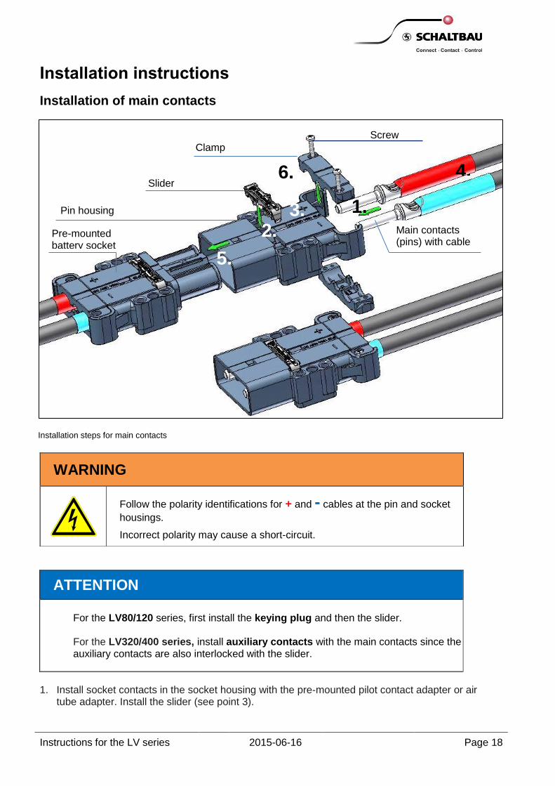
Installation steps for main contacts
ATTENTION
For the LV80/120 series, first install the keying plug and then the slider.
For the LV320/400 series, install auxiliary contacts with the main contacts since the auxiliary contacts are also interlocked with the slider.
1. Install socket contacts in the socket housing with the pre-mounted pilot contact adapter or air
tube adapter. Install the slider (see point 3).
Installation instructions
Installation of main contacts
WARNING
Follow the polarity identifications for + and - cables at the pin and socket
housings.
Incorrect polarity may cause a short-circuit.
Screw
Clamp
Slider
Pin housing
Pre-mounted battery socket
Main contacts (pins) with cable
1. 3. 2.
4.
5.
6.

Instructions for the LV series 2015-06-16 Page 19
2. Push the pin housing on the pre-mounted battery socket. Push the pin contacts with crimped cables – for the LV320/400 series, together with auxiliary contacts, provided these are used – up to the end stop in the contact chamber of the housing.
LV 320/400 correct position main and/or auxiliary contacts before installation of the slider
LV 320/400 wrong position main and/or auxiliary contacts before installation of the slider
Align both main contacts in the housing uniformly to minimise the torsion forces in the cable. In case of short cables, especially ensure that the crimping points are aligned parallel to the resting surface of the cable shoe.
3. The installation of the slider shall be done at room temperature 25 ° C + / - 5 °C. Option 1: One-part slider LV160 S or LV320 S ( Press the slider for fixing the main contacts until it is latched in the housing such that both latching hooks are latched simultaneously as far as possible. (In case of LV80/120, install the keying plug before the slider since it is fixed by the slider.) Option 2: Two-part Slider with a lock (light grey) LV160/250 S or Slider with a lock (black) LV320/400 S The two-piece slider with a lock is made of a base body, “slider”, and a moving part, “lock”. The slider can be assembled only in the unlocked position. Check the correct position before assembling.

Instructions for the LV series 2015-06-16 Page 20
Two-piece slider: View of individual parts LV 160/250 S Slider
Two-piece slider: View of individual parts LV 320/400 S Slider
Slider with a lock in the unlocked condition,
Recess of the lock and the crossbar of the base body are not located above each other (see the arrows)
Slider with a lock in the locked condition,
Recess of the lock and the crossbar of the base body are located above each other (see the arrows) Note: The letter “Z” is visible in the locked condition.
Coding of housing LV320/400 housings:
ATTENTION
In the LV320/400 housings install always the accompanying LV320/400 S Slider with a lock.
Correct installation of LV 160/250 S slider with a lock in LV160/250 housings
False installation of LV 160/250 S slider with a lock in LV320/400 housings
Lock
Slider

Instructions for the LV series 2015-06-16 Page 21
Correct installation of LV320/400 S slider with a lock in LV320/400 housings
Wrong installation of LV 160/250 S slider with a lock in LV320/400 housings
Installation of Slider with a lock: LV 160/250 and LV 320/400
Insert slider in its unlocked position into the housing, push with simultaneous application of force until it locks into the housing
Don´t press the slider in its locked position into the housing! Never press in the slider in center area!
.
Slider assembly with mounting tool
Optional, push the slider with the mounting tool.
Two-sided application of force with mounting tool.
~ 42 mm
Instructions for the LV series 2015-06-16 Page 22
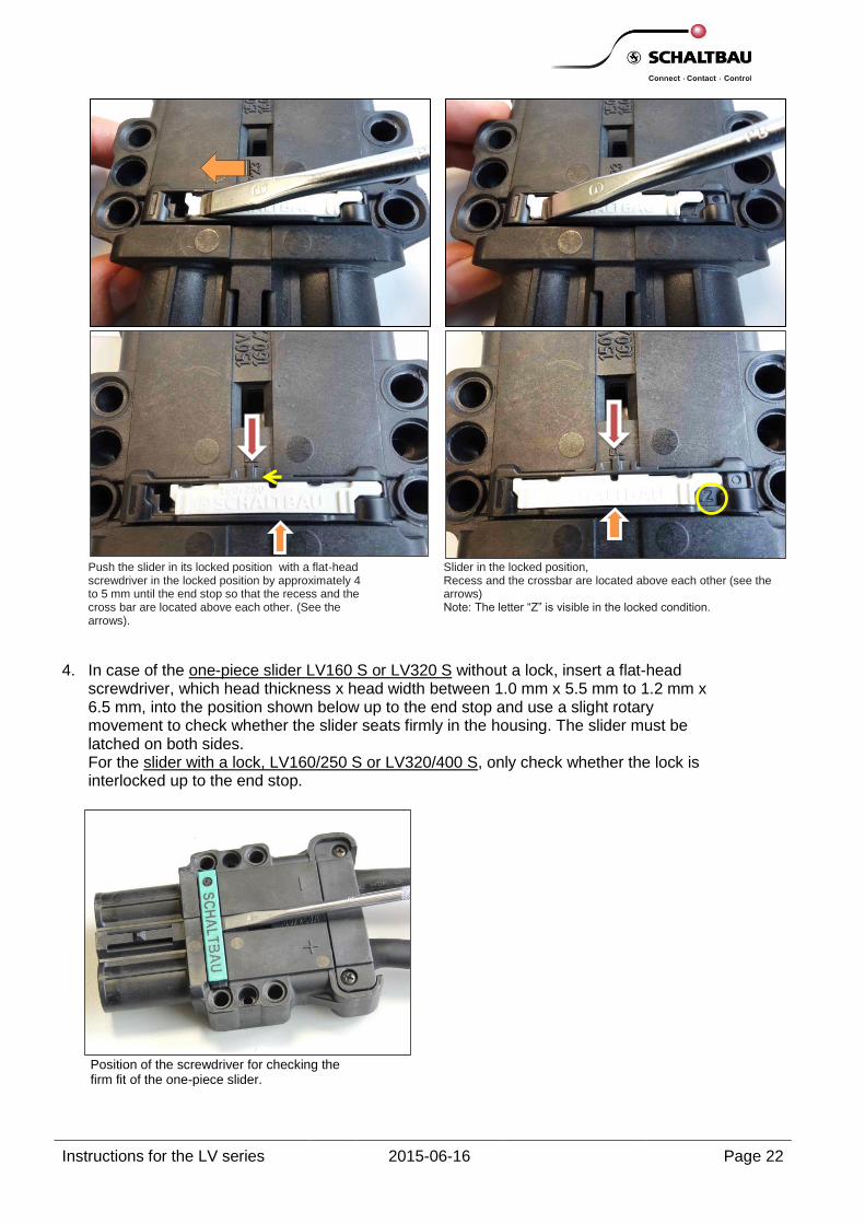
Push the slider in its locked position with a flat-head screwdriver in the locked position by approximately 4 to 5 mm until the end stop so that the recess and the cross bar are located above each other. (See the arrows).
Slider in the locked position, Recess and the crossbar are located above each other (see the arrows) Note: The letter “Z” is visible in the locked condition.
4. In case of the one-piece slider LV160 S or LV320 S without a lock, insert a flat-head
screwdriver, which head thickness x head width between 1.0 mm x 5.5 mm to 1.2 mm x 6.5 mm, into the position shown below up to the end stop and use a slight rotary movement to check whether the slider seats firmly in the housing. The slider must be latched on both sides. For the slider with a lock, LV160/250 S or LV320/400 S, only check whether the lock is interlocked up to the end stop.
Position of the screwdriver for checking the firm fit of the one-piece slider.

Instructions for the LV series 2015-06-16 Page 23
5. Slightly pull cables of contacts - also at cables of auxiliary contacts for LV320/400 series if required - to check whether contacts are correctly fixed.
6. Push the respective housing on the pre-mounted counter housing up to the end stop.
After installing the main contacts, we recommend mating of the connector halves before tightening strain relief screws. This ensures optimum co-axiality of main contacts and enables easy insertion and disconnection of the device and charging connectors.
7. Screw the upper and lower clamps of the strain relief such that all cables are uniformly and reliably secured against pull (see the following images). The tightening torque for screws is 1.5 Nm. Ensure that a suitable cross-recess insert is used.
Uniformly screwed strain relief Non-uniformly screwed strain relief

Instructions for the LV series 2015-06-16 Page 24
Position of the screwdriver for dismantling the the slider.
In case of the slider with a lock, move the lock up to the end stop in the unlocked position before
dismantling. If the lock is not entirely at the unlocked position, the slider may get damaged. When reusing the slider, ensure that there are 4 latching hooks (see chapter “Maintenance of sliders”)
Dismantling the main contacts
The slider must be removed to dismantle the main contacts - even the auxiliary contacts for the LV320/400 series if required. Insert a flat-head screwdriver, which head thickness x head width between 1.0 mm x 5.5 mm to 1.2 mm x 6.5 mm, in the position shown below up to the end stop and use a slight rotary movement to lift the slider slightly from its seat until it unlatches. Reuse the slider only if it is undamaged.

Instructions for the LV series 2015-06-16 Page 25
Installation direction of pilot and auxiliary contacts
For socket contacts, pilot contact adapter is pre-mounted in socket housing.
1. Push pilot contact adapter into connector housing until it latches.
2. After it latches, press the pilot contact adapter against the installation direction to check whether the pilot contact adapter sits firmly.
3. Push pilot contacts / auxiliary contacts (with crimped cables) into the contact chambers of the pilot contact adapter and the housing (auxiliary contacts) till the end stop.
4. Slightly pull at the cables of pilot contacts / auxiliary contacts to check whether the contacts are correctly fixed.
ATTENTION
For LV320/400 series, install auxiliary contacts with the main contacts since the auxiliary contacts are also interlocked with the slider.
Installing the pilot and auxiliary contacts

Instructions for the LV series 2015-06-16 Page 26
WARNING
The connector may not be operated without the pilot contact adapter or without the air tube adapter with a spacer in the socket housing. For the installation location of the connector, ensure that battery acids do not enter the connector as a result of electrolyte circulation.
Extraction tools for pilot and auxiliary contacts
You can refer to the following table for extraction tools to be used depending on contact type and the series.
Series Contacts Tool
LV80
Pilot contacts
LV80 BBC-2.5-Ag
Extraction tool LV80 AWZ-B LV80 SBC-2.5-Ag
Auxiliary contacts
LV80 BBC-2.5-Ag
LV80 SBC-2.5-Ag
LV160
Pilot contacts
BCC-2.5-Ag Extraction tool AWZ-C/H
SCC-2.5-Ag
Auxiliary contacts
LV160 BBC-2.5-Ag Extraction tool LV160 AWZ-B
LV160 SBC-2.5-Ag
LV320
Pilot contacts
BCC-2.5-Ag Extraction tool AWZ-C/H
SCC-2.5-Ag
Auxiliary contacts
LV320 BCC-2.5-Ag Auxiliary contacts are interlocked with the slider LV320 SCC-2.5-Ag
Dismantling the pilot and auxiliary contacts
Instructions for the LV series 2015-06-16 Page 27
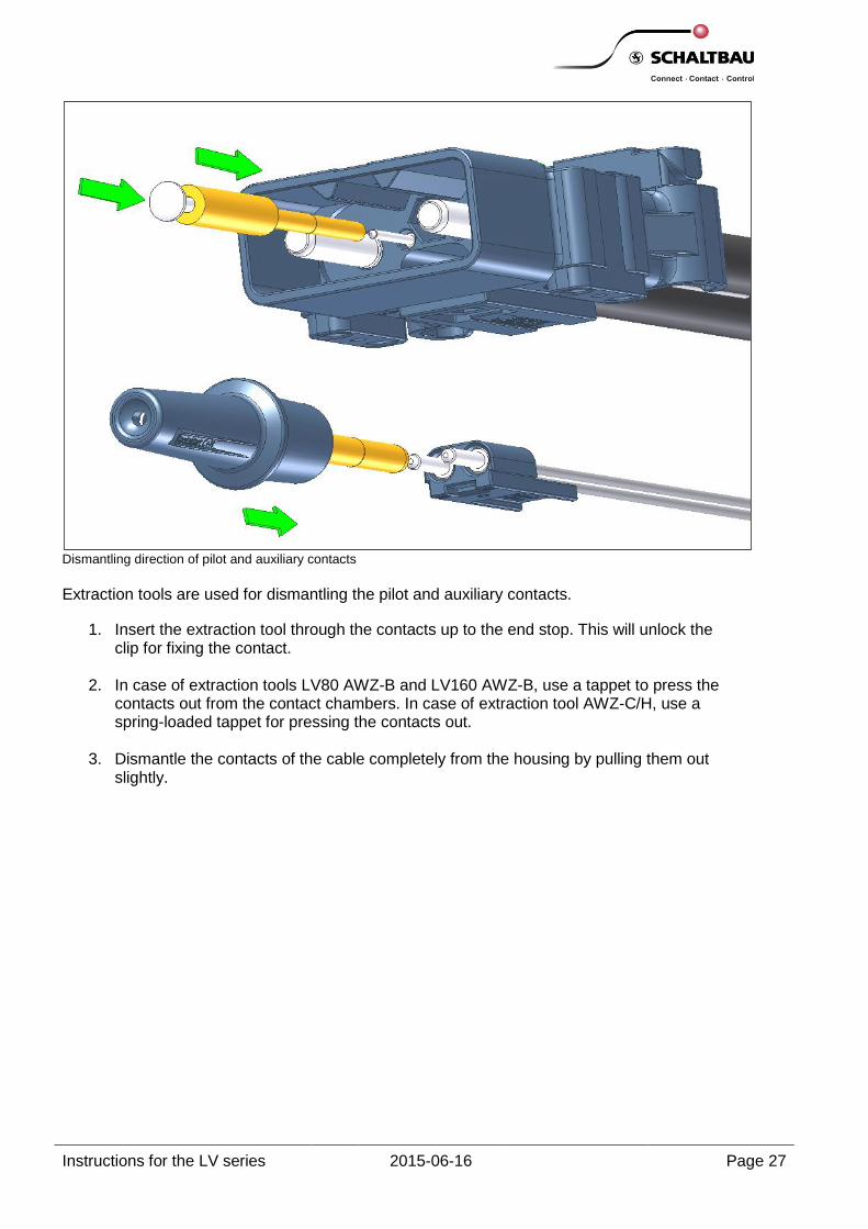
Dismantling direction of pilot and auxiliary contacts
Extraction tools are used for dismantling the pilot and auxiliary contacts.
1. Insert the extraction tool through the contacts up to the end stop. This will unlock the clip for fixing the contact.
2. In case of extraction tools LV80 AWZ-B and LV160 AWZ-B, use a tappet to press the contacts out from the contact chambers. In case of extraction tool AWZ-C/H, use a spring-loaded tappet for pressing the contacts out.
3. Dismantle the contacts of the cable completely from the housing by pulling them out slightly.

Instructions for the LV series 2015-06-16 Page 28
Air tube adapter on the pin side Air tube adapter on the socket side
CAUTION
When using the electrolyte circulation with the air tube adapter, pin and socket housings must be equipped with the air tube adapter. Only then is it ensured that the electrolyte fluid does not reach the connector and reduce the service life of contacts. Pin and socket housing must belong to the same series. Air tube interfaces of old LB series are not compatible with the air tube interfaces of the LV series.
1. Push the air tube (inner Ø 6 mm), wall thickness ≤ 1.5 mm, Shore hardness 73 on the air tube adapter to the maximum possible extent. Use the matching adapter to fix the tubes with larger inner diameters or a larger wall thickness.
2. Push the air tube adapter until it latches in the housing.
3. Then press the air tube adapter against the installation direction to check whether the air tube adapter sits firmly.
4. Insert the spacer in the socket housing up to the end stop.
The connecting piece is an adapter for fixing the air tubes with an inner diameter of: Ø 9 to 10 mm Ø 6 mm and a wall thickness > 1.5 mm
LV80/160/320 V-S 6/6
Adapter for 6 mm air tubes with wall thickness > 1.5 mm
LV80/160/320 V-S 6/10
Adapter from 6 mm to 10 mm
Installing the air tube adapter
The air tube adapter and the spacer are always enclosed with the socket housing.
LV…. DS-L spacer
LV…. LV-P air tube adapter
LV…. LV-S air tube adapter
Instructions for the LV series 2015-06-16 Page 29
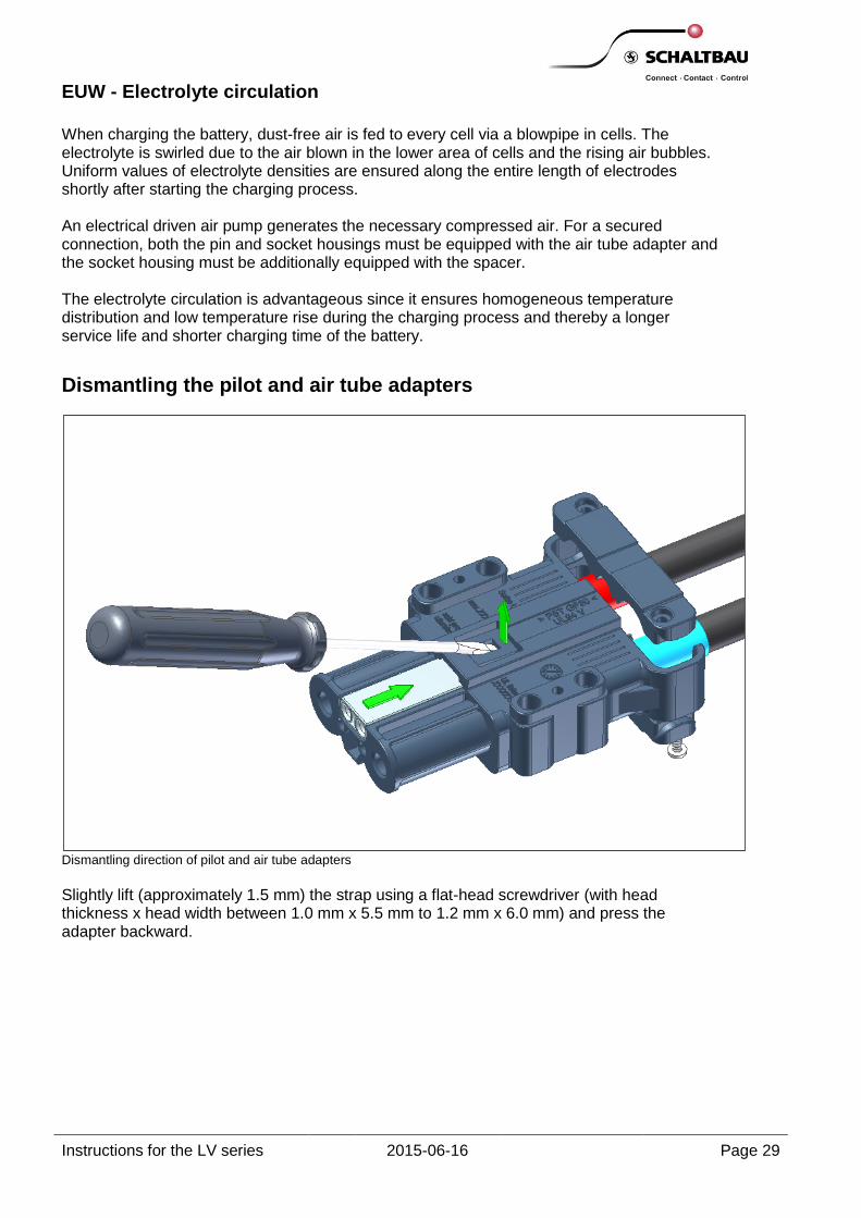
EUW - Electrolyte circulation
When charging the battery, dust-free air is fed to every cell via a blowpipe in cells. The electrolyte is swirled due to the air blown in the lower area of cells and the rising air bubbles. Uniform values of electrolyte densities are ensured along the entire length of electrodes shortly after starting the charging process. An electrical driven air pump generates the necessary compressed air. For a secured connection, both the pin and socket housings must be equipped with the air tube adapter and the socket housing must be additionally equipped with the spacer. The electrolyte circulation is advantageous since it ensures homogeneous temperature distribution and low temperature rise during the charging process and thereby a longer service life and shorter charging time of the battery.
Dismantling direction of pilot and air tube adapters
Slightly lift (approximately 1.5 mm) the strap using a flat-head screwdriver (with head thickness x head width between 1.0 mm x 5.5 mm to 1.2 mm x 6.0 mm) and press the adapter backward.
Dismantling the pilot and air tube adapters
Instructions for the LV series 2015-06-16 Page 30
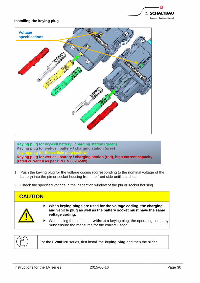
Installing the keying plug
1. Push the keying plug for the voltage coding (corresponding to the nominal voltage of the battery) into the pin or socket housing from the front side until it latches.
2. Check the specified voltage in the inspection window of the pin or socket housing.
CAUTION
When keying plugs are used for the voltage coding, the charging and vehicle plug as well as the battery socket must have the same voltage coding.
When using the connector without a keying plug, the operating company must ensure the measures for the correct usage.
For the LV80/120 series, first install the keying plug and then the slider.
Keying plug for dry-cell battery / charging station (green) Keying plug for wet-cell battery / charging station (grey) Keying plug for the vehicle plug (yellow) Keying plug for wet-cell battery / charging station (red), high current capacity (rated current II as per DIN EN 0623-589)
Voltage
specifications

Instructions for the LV series 2015-06-16 Page 31
LV to H1 handle (black) LV to H2 handle (red) Snap-on
LV to H1-SCH handle (black) LV to H2-SCH handle (red)
Screwable
LV160/320 H3 handle (black) LV160/320 H4 handle (red) Snap-on
Handles (images on the left and right sides) are snap-on. Latch the handle in the provided fixing holes. The snap-on handle without screws may slip from the housing after a forced impact on the connector, e.g. due to falling. The handle must then be latched again into fixing holes. In case of LV160/250 and LV320/400, the handle can also be fixed using two screws. The tightening torque for screws is 0.5 Nm. Alternatively, screwable handles (top-centre image) are also available. The tightening torque for screws is 2.0 Nm.
Information regarding the expertise that is absolutely essential for maintenance is given in section Misuse. Before starting any work on the device and charging connectors, always ensure that these are deenergised. In addition to the primary current circuits, pay attention to the pilot and auxiliary current circuits.
WARNING
After improper handling and additionally at least after every 1000 operating hours, all device and charging connector components and their interface components must be subjected to maintenance and checked for defects during visual inspections and, if required, the parts must be replaced immediately.
Also check the opposite side for the damage (substitute batteries and charging devices).
Keep the device and charging connectors clean and, if required, clean them using compressed air. Contaminations may lead to leakage currents and increased insertion forces.
Installing the handles of different models
Ensure that a suitable cross-recess insert is used.
Maintenance
Instructions for the LV series 2015-06-16 Page 32
WARNING
Before starting work on the device and charging connectors, always adhere to the following safety rules:
Switch off and secure against restarting
Disconnect the battery cables
Ensure that the parts are deenergised (charging device, battery)
Enclose or cover the neighbouring live parts such as pilot and auxiliary contacts.
Pay attention to the electrical polarity at the connection points of charging devices and charging cables. Mix-ups may lead to damage.
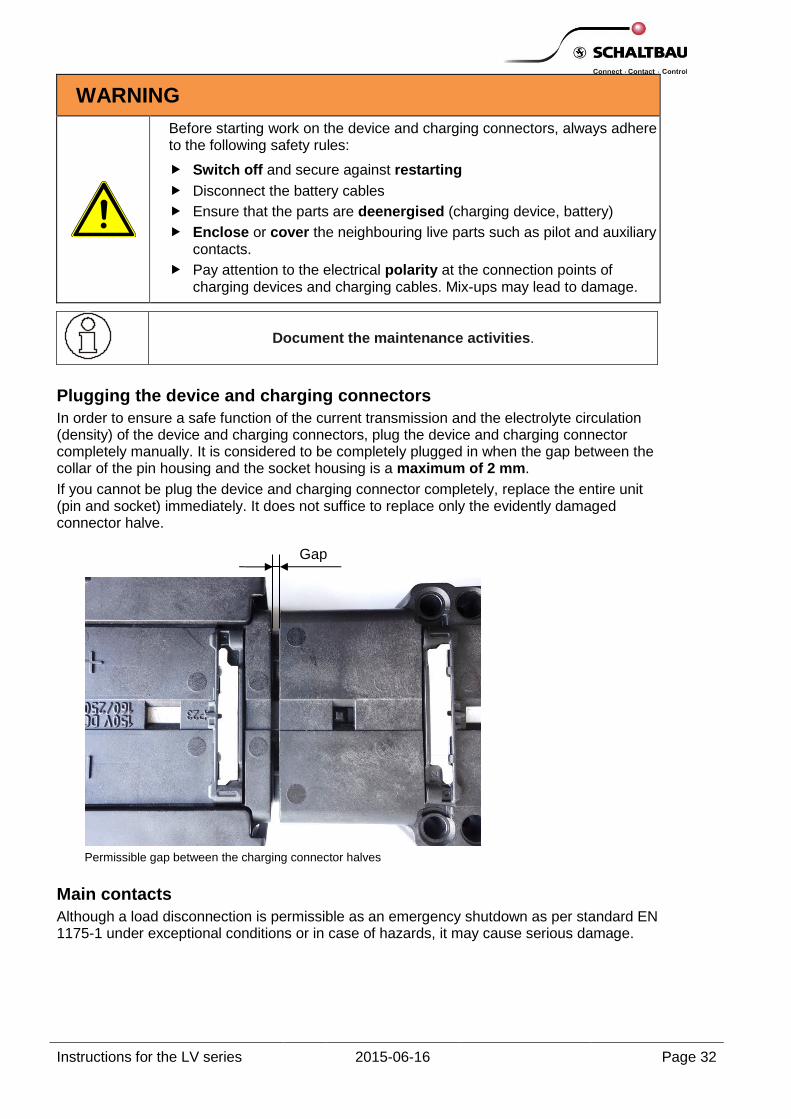
Plugging the device and charging connectors
In order to ensure a safe function of the current transmission and the electrolyte circulation (density) of the device and charging connectors, plug the device and charging connector completely manually. It is considered to be completely plugged in when the gap between the collar of the pin housing and the socket housing is a maximum of 2 mm.
If you cannot be plug the device and charging connector completely, replace the entire unit (pin and socket) immediately. It does not suffice to replace only the evidently damaged connector halve.
Permissible gap between the charging connector halves
Main contacts
Although a load disconnection is permissible as an emergency shutdown as per standard EN 1175-1 under exceptional conditions or in case of hazards, it may cause serious damage.
Document the maintenance activities.
Gap

Instructions for the LV series 2015-06-16 Page 33
Depending on the plugging frequency under emergency shutdown conditions or overload, the material is deposited on or removed from the contacts. Material is deposited in the contact zone. The transition resistance increases constantly and this is associated with undue heating of the device and charging connectors as well as the connected cable.
There is a risk of fire.
It may lead to increased insertion forces or complete plugging may not be possible.
CAUTION
Check the following points at the latest after every improper handling, every plugging and disconnection under load, every emergency shutdown as well as at least after every 1000 operating hours:
1. Plug and/or disconnect the device and charging connectors manually with higher force application.
2. Do not plug both connector halves completely using your hands (see the gap between the collar of the pin housing and the socket housing).
3. Check whether the unit is heated > 65K during operation with respect to the ambient temperature of the housing or cables.
4. Check whether material deposit and/or removal, contamination or discolouration due to dirt, wear and mediums such as acids can be detected during a visual inspection.
5. Move or displace the main contacts by pulling the cables slightly.
6. Check whether the position of the pin and socket contacts in the housing deviates with respect to the drawing. (See the drawing “Position of socket contacts, keying plug” below).
Immediately replace the device and charging connectors that show one of the aforementioned indications.
WARNING
If the device and charging connectors carry current when inserting and disconnecting, hazardous light arcs may be generated. This may lead to premature ageing of contacts, increased insertion forces and overheating. It may also lead to a fire.
If the battery releases hydrogen, there is a risk of explosion. Persons are also at risk in this case.
Ensure adequate ventilation.
Switch OFF the charger before inserting or disconnecting the connector.
Instructions for the LV series 2015-06-16 Page 34
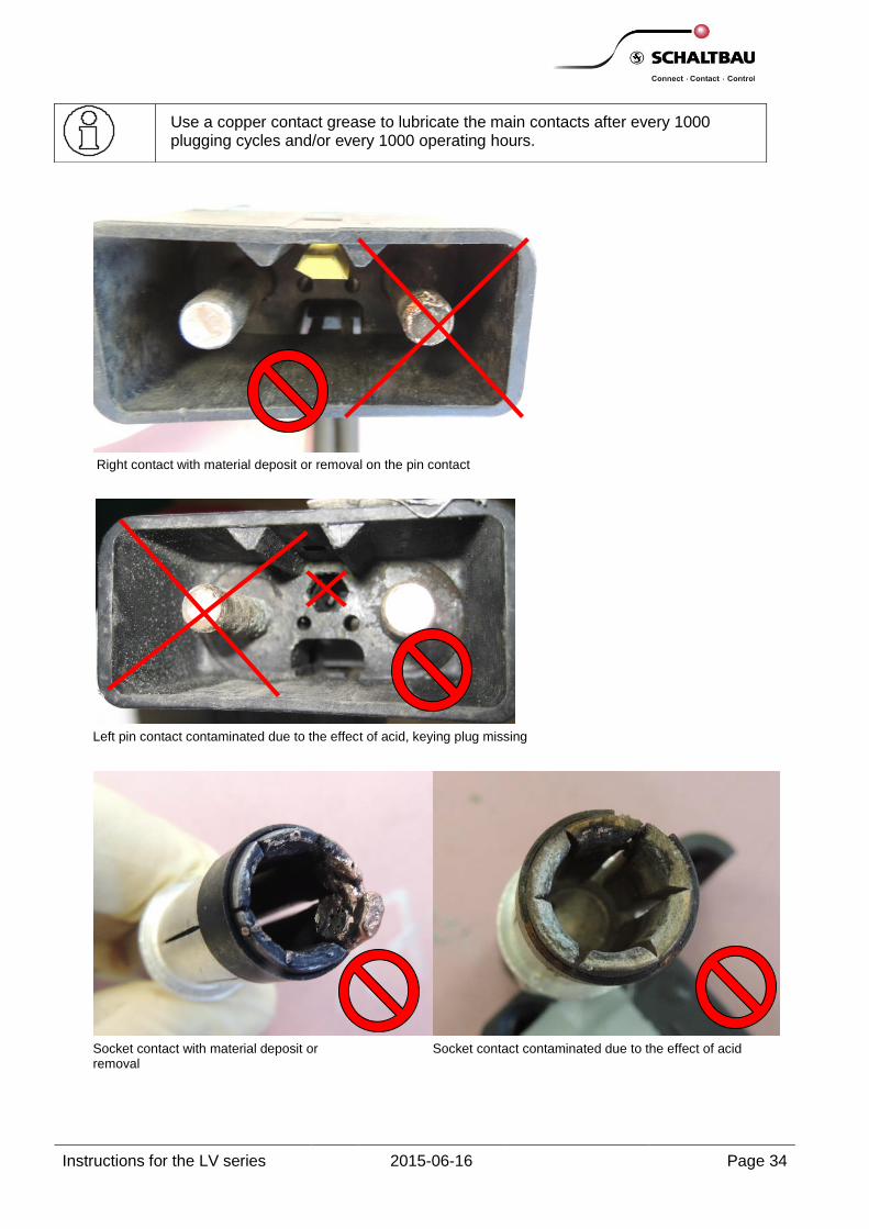
Right contact with material deposit or removal on the pin contact
Left pin contact contaminated due to the effect of acid, keying plug missing
Socket contact with material deposit or removal
Socket contact contaminated due to the effect of acid
Use a copper contact grease to lubricate the main contacts after every 1000 plugging cycles and/or every 1000 operating hours.

Instructions for the LV series 2015-06-16 Page 35
Position of pin contacts, keying plug
Position of socket contacts, keying plug
Series L1 [mm], ± 0.8 L2 [mm], 0/+1.5 L3 [mm], ± 1.55 L4 [mm], ± 2.2 L5 [mm], ± 1
LV80/120 32
2
1.5 26.5 1.5
LV160/250 38 4 40 3
LV320/400 41 10 48.9

Instructions for the LV series 2015-06-16 Page 36
Pin and socket housings
Improper handling of device and charging connectors, e.g. due to forced impact on the floor, may damage the pin and socket housings, especially in the area of strain relief.
CAUTION
Check the following points after every instance of improper handling and at least after every 1000 operating hours:
If the pin and socket housings show broken points, visible cracks or deformations, contamination or discolouration due to dirt, wear and mediums such as acids during the visual inspection, replace the defective components immediately.
Slider
The slider is used to hold the main contacts and ensures that users cannot touch the contacts during operation. Improper handling of device and charging connectors, e.g. due to forced impact on the floor, may lead to broken points, visible cracks and deformations or falling of the slider or change the position of the slider.
CAUTION
Check the following points after every instance of improper handling and at least after every 1000 operating hours:
1. Whether the slider is in the device and charging connectors.
2. Whether the one-piece slider (without a lock) fits firmly in the device and charging connectors. Check the fixing of the slider by slightly lifting at the slider using a flat-head screwdriver with (head thickness x head width between 1.0 mm x 5.5 mm to 1.2 mm x 6.5 mm) (see images 4 and 5). The slider must be latched on both sides.
Optional
For the slider with a lock, check whether the lock is still at the interlocked position. If required, interlock the lock again.
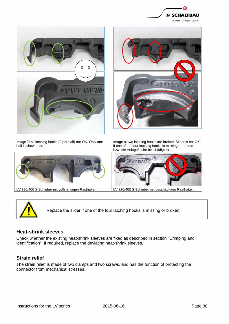
3. If the slider shows broken points, visible cracks or deformations (images 7 and 8), contamination or discolouration due to dirt, wear and mediums such as acids during the visual inspection, replace the defective components immediately.

Instructions for the LV series 2015-06-16 Page 37
Image 1: Slider is in the connector. OK. Image 2: Slider is not in the connector. The
charging connector may not be used.
Image 3: Slider in the locked position. OK. Slider is mounted parallel to the housing.
Image 4: Slider is not parallel to the housing and hence is not in the correct position. Left side of the slider is not latched.
Image 5: Check the fixing of the slider by slightly lifting at the slider using a flat-head screwdriver. Slider must interlock on both sides.
Image 6: Slider with a lock in the locked condition,
Recess and the crossbar are located above each other (see the arrows)
Instructions for the LV series 2015-06-16 Page 38
Image 7: all latching hooks (2 per half) are OK. Only one half is shown here
Image 8: two latching hooks are broken. Slider is not OK if one oft he four latching hooks is missing or broken bzw. die Anlagefläche beschädigt ist.
LV 320/400 S Schieber mit vollständigen Rasthaken LV 320/400 S Schieber mit beschädigten Rasthaken
Heat-shrink sleeves
Check whether the existing heat-shrink sleeves are fixed as described in section "Crimping and identification". If required, replace the deviating heat-shrink sleeves.
Strain relief
The strain relief is made of two clamps and two screws, and has the function of protecting the connector from mechanical stresses.
Replace the slider if one of the four latching hooks is missing or broken.
Instructions for the LV series 2015-06-16 Page 39
Clamp, screws for the clamp
CAUTION
Check the following points after every instance of improper handling and at least after every 1000 operating hours:
1. If the clamps show broken points, visible cracks or deformations,
contamination or discolouration due to dirt, wear and mediums such as acids during the visual inspection, replace the defective components immediately.
2. Tighten the screws of the strain relief with a tightening torque of 1.5 Nm.
Handle LV (snap-on, screw-in)
Improper handling of device and charging connectors, e.g. due to forced impact on the floor, may lead to broken points, visible cracks and deformations in the handle.
After every instance of improper handling as well as at least after every 1000 operating hours, check the handle for defects during visual inspections and, if required, replace it immediately.
Pilot contact adapter and air tube adapter
WARNING
Check whether socket housing includes pilot contact adapter or air tube adapter and spacer. The connector may be operated only if socket housing includes pilot contact adapter or air tube adapter and spacer.
Pilot and auxiliary contacts (pin, socket)
Check whether the pilot or auxiliary contact is latched by slightly pulling at the cables.
Never pull or press the cables for inserting or pulling out the connectors even if a handle is not provided. If the handle is missing, directly hold the housing of the connector.
Instructions for the LV series 2015-06-16 Page 40
Electrolyte circulation
Escaping mediums such as acids (condensate of the battery electrolyte fluid) may affect the current transmission and the insertion and disconnection forces of the charging connector severely and lead to severe heating and sometimes even short circuits.
CAUTION
Check the following points after every instance of improper handling and at least after every 1000 operating hours:
Air tube adapter and spacer (socket housing) Air tube adapter (ping housing) Adapter (air tube adapter)
1. If the aforementioned parts show damaged sealing outline, broken points, visible cracks or deformations, contamination or discolouration due to dirt, wear and mediums such as acids during the visual inspection, replace the defective components immediately.
2. Check whether the connecting tube has the correct quality and dimensions for a safe and leak-tight connection and whether the adapter has been used for the intended purpose.
Keying plug
If the keying plug is not available or if it is broken, it may lead to incorrect plugging and incorrect voltage/current pairing.
WARNING
When using the connector without a keying plug, the operating company must ensure the measures for the correct usage.
CAUTION
Check the following points after every instance of improper handling and at least after every 1000 operating hours:
1. If the keying plugs show damage in the plug area, broken points, visible cracks or deformations, contamination or discolouration due to dirt, wear and mediums/liquids such as acids during the visual inspection, replace the defective components immediately.
2. Check the position and the firm fitting of the keying plug.
3. Check whether the charging and vehicle plugs as well as the battery socket have the correct voltage coding. Replace the incorrect keying plugs immediately.

Instructions for the LV series 2015-06-16 Page 41
Cables
CAUTION
Check the following points after every instance of improper handling and at least after every 1000 operating hours:
If cables show damage or detachment of cable insulation and/or burnt cable insulation during visual inspections, replace defective components immediately.
Checklist for the users of industrial trucks Tests to be conducted Criterion Daily
before commissioning
After an incident
1,2 Completed
1.) Check whether the device and charging connectors can be completely plugged manually.
Gap of a maximum of 2 mm
Yes Yes 1,2
2.) Check whether the main contacts show material deposit
and/or removal, contamination or discolouration due to dirt, wear and mediums such as acids during a visual inspection.
Changes not visible Yes
Yes 1
3.) Check the latching and the position of main contacts and keying plugs.
Adhere to the dimensions specified in the drawing
Yes Yes 1,2
4.) Check whether the pin and socket housings, slider, clamps, handles, pilot adapter, air tube adapter, adapters and keying plugs show broken points, visible cracks and
deformation, contamination or discolouration due to dirt, wear and mediums such as acids during a visual inspection.
Defects not visible, Handle, pilot or air tube adapter latched
Yes Yes 2
5.) Check whether the slider exists and whether it latches. Optional: in case of a slider with a lock, check the
position of the lock of the sliding part.
Latched on both sides, optional lock
interlocked
Yes Yes 2
6.) If the electrolyte circulation is available, check the air tube adapter and spacer (socket housing), air tube adapter (pin housing), adapter (air tube adapter) for damage to the
sealing line, broken points, visible cracks and deformations, contamination or discolouration due to dirt, wear or mediums/liquids such as acids.
Defects not visible Yes Yes 2
7.) Check the insulation of cables (cable sheath) for damage, burnt cracks and detachments during a visual inspection.
Defects not visible Yes Yes 1,2
1 After an emergency shutdown or plugging and disconnecting under load. 2
After improper handling, e.g. forced impact.
Maintenance points
These checklists do not replace the obligation of reading and following the crimping, installation and maintenance instructions. They have been prepared only as an aid for the safe operation and use of industrial trucks as far as device and charging connectors are concerned.
Instructions for the LV series 2015-06-16 Page 42
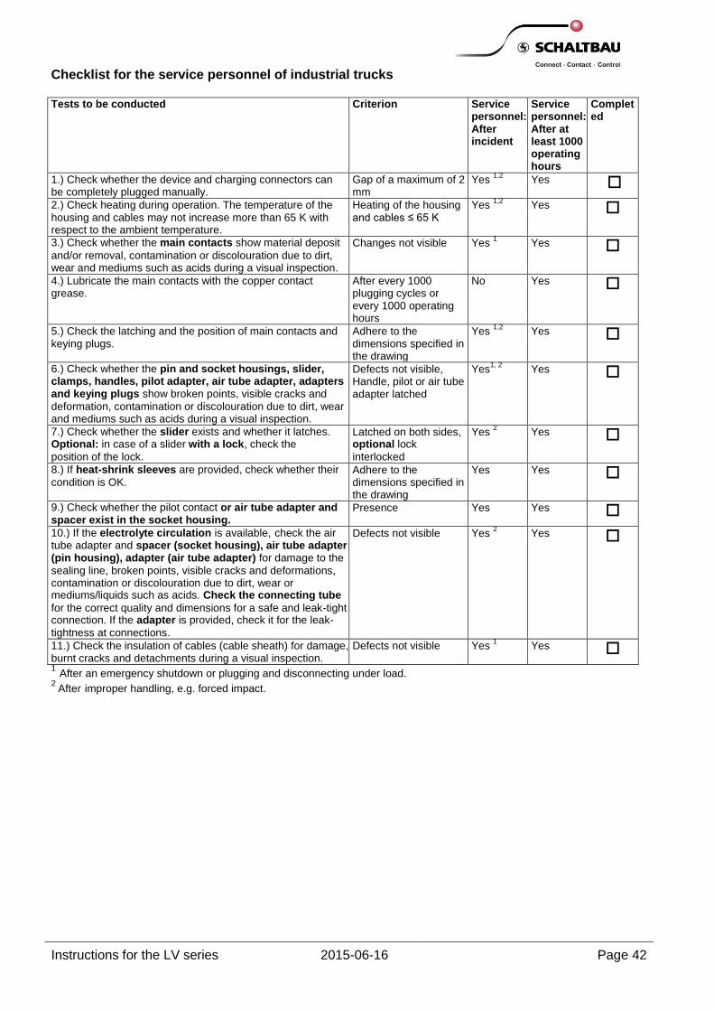
Checklist for the service personnel of industrial trucks Tests to be conducted Criterion Service
personnel: After incident
Service personnel: After at least 1000 operating hours
Completed
1.) Check whether the device and charging connectors can be completely plugged manually.
Gap of a maximum of 2 mm
Yes 1,2
Yes
2.) Check heating during operation. The temperature of the housing and cables may not increase more than 65 K with respect to the ambient temperature.
Heating of the housing and cables ≤ 65 K
Yes 1,2
Yes
3.) Check whether the main contacts show material deposit
and/or removal, contamination or discolouration due to dirt, wear and mediums such as acids during a visual inspection.
Changes not visible Yes 1
Yes
4.) Lubricate the main contacts with the copper contact grease.
After every 1000 plugging cycles or every 1000 operating hours
No Yes
5.) Check the latching and the position of main contacts and keying plugs.
Adhere to the dimensions specified in the drawing
Yes 1,2
Yes
6.) Check whether the pin and socket housings, slider, clamps, handles, pilot adapter, air tube adapter, adapters and keying plugs show broken points, visible cracks and
deformation, contamination or discolouration due to dirt, wear and mediums such as acids during a visual inspection.
Defects not visible, Handle, pilot or air tube adapter latched
Yes1, 2
Yes
7.) Check whether the slider exists and whether it latches. Optional: in case of a slider with a lock, check the
position of the lock.
Latched on both sides, optional lock
interlocked
Yes 2 Yes
8.) If heat-shrink sleeves are provided, check whether their
condition is OK. Adhere to the dimensions specified in the drawing
Yes Yes
9.) Check whether the pilot contact or air tube adapter and spacer exist in the socket housing.
Presence Yes Yes
10.) If the electrolyte circulation is available, check the air tube adapter and spacer (socket housing), air tube adapter (pin housing), adapter (air tube adapter) for damage to the
sealing line, broken points, visible cracks and deformations, contamination or discolouration due to dirt, wear or mediums/liquids such as acids. Check the connecting tube
for the correct quality and dimensions for a safe and leak-tight connection. If the adapter is provided, check it for the leak-
tightness at connections.
Defects not visible Yes 2 Yes
11.) Check the insulation of cables (cable sheath) for damage, burnt cracks and detachments during a visual inspection.
Defects not visible Yes 1 Yes
1 After an emergency shutdown or plugging and disconnecting under load. 2
After improper handling, e.g. forced impact.

Instructions for the LV series 2015-06-16 Page 43
ATTENTION
Use only the designated spare parts from device and charging connector series.
SCHALTBAU GmbH is not liable for damages if crimping, installation and maintenance instructions are not followed or followed only partially or original SCHALTBAU GmbH spare parts are not used or if modified parts are used or connector halves from different series are combined when using the electrolyte circulation.
Air tube interfaces of connector halves of old LB series are not compatible with the air tube interfaces of connector halves of the LV series.
DIN EN 1175-1; VDE 0117-1 / auth. DKE // Sicherheit von Flurförderzeugen - Elektrische Anforderungen - Teil 1: Allgemeine Anforderungen für Flurförderzeuge mit batterieelektrischem Antrieb. - [s.l.] : Beuth, 2011-06. DIN EN 60352-2 / auth. DKE // Teil 2: Crimpverbindungen - Allgemeine Anforderungen, Prüfverfahren und Anwendungshinweise . - [s.l.] : Beuth, 2006-11. DIN EN 60512-5-2 / auth. DKE // Steckverbinder für elektronische Einrichtungen - Mess- und Prüfverfahren - Teil 5-2: Prüfungen der Strombelastbarkeit; Prüfung 5b: Strombelastbarkeit (Derating-Kurve). - [s.l.] : Beuth, 2002-01. DIN EN 61238-1 / auth. DKE // Pressverbinder und Schraubverbinder für Starkstromkabel für Nennspannungen bis einschließlich 36 kV (Um = 42 kV) - Teil 1: Prüfverfahren und Anforderungen. - [s.l.] : Beuth, 2004-03. DIN VDE 0282-6 / auth. DKE // Starkstromleitungen mit vernetzter Isolierhülle für Nennspannungen bis 450/750 V - Teil 6: Lichtbogenschweißleitungen. - [s.l.] : Beuth, Februar 2005. DIN VDE 0623-589 / auth. DKE im DIN und VDE // Geräte-Steckvorrichtungen für Elektro-Flurförderzeuge, Bauformen 80, 160, 320, 640 / 150 V - Teil 589: Anschlussmaße, Werkstoff, Kennzeichnung. - [s.l.] : Beuth, Juni 2011. VdS 2259 / auth. VdS-Schadensverhütung GmbH // VdS-Richtlinie zur Schadenverhütung 2259 „Batterieladeanlagen für Elektrofahrzeuge“. - Köln : VdS-Schadensverhütung GmbH, 2010-12.
Ordering the spare parts
Bibliography

Instructions for the LV series 2015-06-16 Page 44
The latest version of spare parts can be downloaded from www.schaltbau-gmbh.com/de/Download/.
Pos. Designation
Ordering code
Remark
LV320/400 LV160/250 LV80/120
1a
1b
Pin housing
Socket housing
LV320/400 G-P
LV320/400 G-SP
LV320/400 G-SL
LV160/250 G-P
LV160/250 G-SP
LV160/250 G-SL
LV80/120 G-P
LV80/120 G-SP
LV80/120 G-SL
Housing for pin contacts Socket housing with Pos. 10a pre-mounted Socket housing with Pos. 15a enclosed
2 Slider LV320/400 S
LV160/250 S
LV80 S Interlocked main contacts (for LV320, even auxiliary contacts)
3 Clamp LV320 D LV160 D LV 80 D 2x strain relief
4 Screw for clamp
SC 3.5x19
SC 3.5x25
SC 3.5x19
---
SC 3.5x16
---
2x self-tapping screws for strain relief: Wire gauge maximum 50 mm² Wire gauge 75/90 mm²
5 Keying plug
Red Red
Grey Green
Yellow
LV250/400 NrS LV250/400 NrP LV160/320 Ngr LV160/320 Tgn LV160/320 Uge
LV120 NrS LV120 NrP LV80 Ngr LV80 Tgn LV80 Uge
For battery socket, high current, wet For charging station, high current, wet For battery socket/charging, wet For battery socket/charging, dry For vehicle plug
6 Main contact
Socket 95 mm² Socket 70 mm² Socket 50 mm² Socket 25 mm²
LV320 S10/95 LV320 S10/70 LV320 S10/50
---
--- ---
LV160/250 S8.5/50 ---
--- --- ---
LV80/120 S6/25
2x main contacts for battery socket
7 Main contact
Pin 95 mm² Pin 70 mm² Pin 50 mm² Pin 25 mm²
LV320 P10/95 LV320 P10/70 LV320 P10/50
---
--- ---
LV160 P8.5/50 ---
--- --- ---
LV80 P6/25
2x main contacts for charging station/vehicle plug
--- Reducer
Reducer 70/50 Reducer 50/35 Reducer 50/25 Reducer 25/16
LV RH70/50 LV RH50/35
--- ---
--- LV RH50/35 LV RH50/25
---
--- --- ---
LV RH25/16
from 70 mm² to 50 mm² from 50 mm² to 35 mm² from 50 mm² to 25 mm² from 25 mm² to 16 mm²
8
9 Auxiliary contacts
Socket 2.5 mm² Pin 2.5 mm²
LV320 BCC-2.5-Ag LV320 SCC-2.5-Ag
LV160 BBC-2.5-Ag LV160 SBC-2.5-Ag
LV80 BBC-2.5-Ag LV80 SBC-2.5-Ag
2x auxiliary contacts for battery socket 2x auxiliary contacts for charging station/vehicle plug
10a
10b Pilot contact adapter
Socket housing Pin housing
LV160/320 PA-S LV160/320 PA-P
LV80 PA-S LV80 PA-P
Adapter for pilot contacts, sockets Adapter for pilot contacts, pins
11
12 Pilot contacts
Socket 2.5 mm² Pin 2.5 mm²
BCC-2.5-Ag SCC-2.5-Ag
LV80 P-S/S LV80 P-P/S
2x pilot contacts for battery socket 2x pilot contacts for charging station/vehicle plug
13
14 Pilot contact set
Adapter + socket contacts Adapter + pin contacts
LV160/320 P-S/S LV160/320 P-P/S
LV80 P-S/S LV80 P-P/S
Set, consisting of positions 10a, 11 Set, consisting of positions 10b, 12
15a
15b
15c
Air tube adapter Spacer Air tube adapter
Socket housing Socket housing
Pin housing
LV160/320 LV-S LV160/320 DS-L
LV160/320 LV-P
LV80 LV-S LV80 DS-L
LV80 LV-P
For tube with inner Ø 6 mm Fuse of the air tube adapter (Pos. 15a) in socket housing (Pos. 1b) For tube with inner Ø 6 mm ---
--- Adapter Air tube adapter LV80/160/320 V-S 6/6
LV80/160/320 V-S 6/10 for tube diameter 6 mm For tube diameter 9 to 10 mm
16 Handle Black, snap-on
Red, snap-on; black, screwable Red, screwable
LV160/320 H3 LV160/320 H4
LV160/320 H1/S LV160/320 H2/S
LV80 H1 LV80 H2
LV80 H1/S LV80 H2/S
Snap-on on socket / Pin housing Screw-in on socket / Pin housing, including screws
List of spare parts

Instructions for the LV series 2015-06-16 Page 45
Notes

Schaltbau GmbHFor detailed information on our products and services visit our website – or give us a call!
Schaltbau GmbH Hollerithstrasse 5 81829 Munich Germany
Phone +49 89 9 30 05-0 Fax +49 89 9 30 05-350 Internet www.schaltbau-gmbh.com e-Mail [email protected]
Connectors
Connectors manufactured to industry standards
Connectors to suit the special requirements of communications engineering (MIL connectors)
Charging connectors for battery-powered machines and systems
Connectors for railway engineering, including UIC connectors
Special connectors to suit customer requirements
Snap-action switches Snap-action switches with positive opening operation
Snap-action switches with self-cleaning contacts
Enabling switches
Special switches to suit customer requirements
Contactors Single and multi-pole DC contactors
High-voltage AC/DC contactors
Contactors for battery powered vehicles and power supplies
Contactors for railway applications
Terminal bolts and fuse holders
DC emergency disconnect switches
Special contactors to suit customer requirements
Electrics for rolling stock
Equipment for driver's cab
Equipment for passenger use
High-voltage switchgear
High-voltage heaters
High-voltage roof equipment
Equipment for electric brakes
Design and engineering of train electrics to customer requirements
Electrical Components and Systems for Railway Engineering and Industrial Applications
with compliments:
RoHS2011/65/EC
Schaltbau
Qua
lity y
ou can count on
Schaltbau
Qua
lity y
ou can count on
Schaltbau GmbH manufactures in
compliance with RoHS.
The production facilities of Schaltbau GmbH have been IRIS certified since
2008.
Certified to DIN EN ISO 14001
since 2002. For the most recent certificate visit
our website.
Certified to DIN EN ISO 9001
since 1994. For the most recent certificate visit
our website.
Printed in Germany
We reserve the right to make technical alterations without prior notice.
For updated product information visit www.schaltbau-gmbh.com..