Embed Size (px)
Citation preview
7/27/2019 MAN_mod
http://slidepdf.com/reader/full/manmod 1/84
INTRODUCTION TO THE M ANUALThe first edition of the manual was dedicated to the techniques that were utilised in restoring
the rivers Cole and Skerne in the autumn of 1995. It was RRC’s intention that the manual would be regularly expanded to include additional techniques drawn from other notableprojects, particularly those that feature different types of rivers, e.g. in upland areas.
The first of these ‘updates’ is included within this web version. These additional 20 techniques,taken from 15 different projects, begin to increase the range of river types covered by the Manual.
The techniques are presented in 11 separate parts of the manual, each part encompassing a significant activity, or objective, that may typically be included in a restoration project brief,e.g. Part 4: Revetting and supporting river banks.
Each Part comprises examples of techniques that may be useful in achieving the specificobjectives, e.g. Technique 4.1: Spiling revetment.
Experience has shown that river restoration projects are most successful if a clear set of aimsand priorities are established at the outset, and that one of the first outputs is a vision plan forthe future prepared without undue regard to constraints of funding, etc. The plan may then bescaled down to suit what is achievable in the short term, in the knowledge that initial works cansafely be followed up later to achieve the full potential of the site.
Recognising what the full potential of any site may be is far from straightforward. It demandsmuch practical experience, knowledge and sound judgement which few can rightly claim topossess because river restoration is only recently being practised on a significant scale. In thesecircumstances, the sharing of knowledge and experience is of particular importance and willremain so for some years to come.
RRC hope that the manual will assist practitioners to gain an understanding of what has gonebefore them so that each new project benefits from ideas that may be incorporated andimproved upon. Inspiration for new ideas may also occur, thereby furthering the practicalknowledge available.
The importance of river restoration projects should not overshadow the countless opportunities
to incorporate its principles in almost any river management activity. Several techniquesfeatured are equally appropriate to small-scale operations such as creating a ford (Part 8) orcreating an outfall to a river (Part 9). Equally, the principles of river restoration may contributemuch to major flood defence projects so that environmental benefit compliments improvedprotection.
Readers are encouraged to register their interest in receiving updated and additional entries tothe manual by contacting RRC. Similarly, readers are encouraged to contact RRC if they wishto contribute any new technique to future editions. Full contact details for RRC can be foundat www.the RRC.co.uk.
For the Web
0 200m
N
WaterlooStream
New damboards
Mill
COLESHILL
1.3Restoredmeander
5.1 New bifurcation
weir
1.2New channel
R C o l e
M i l l l e a t
D r a
i n
6.1
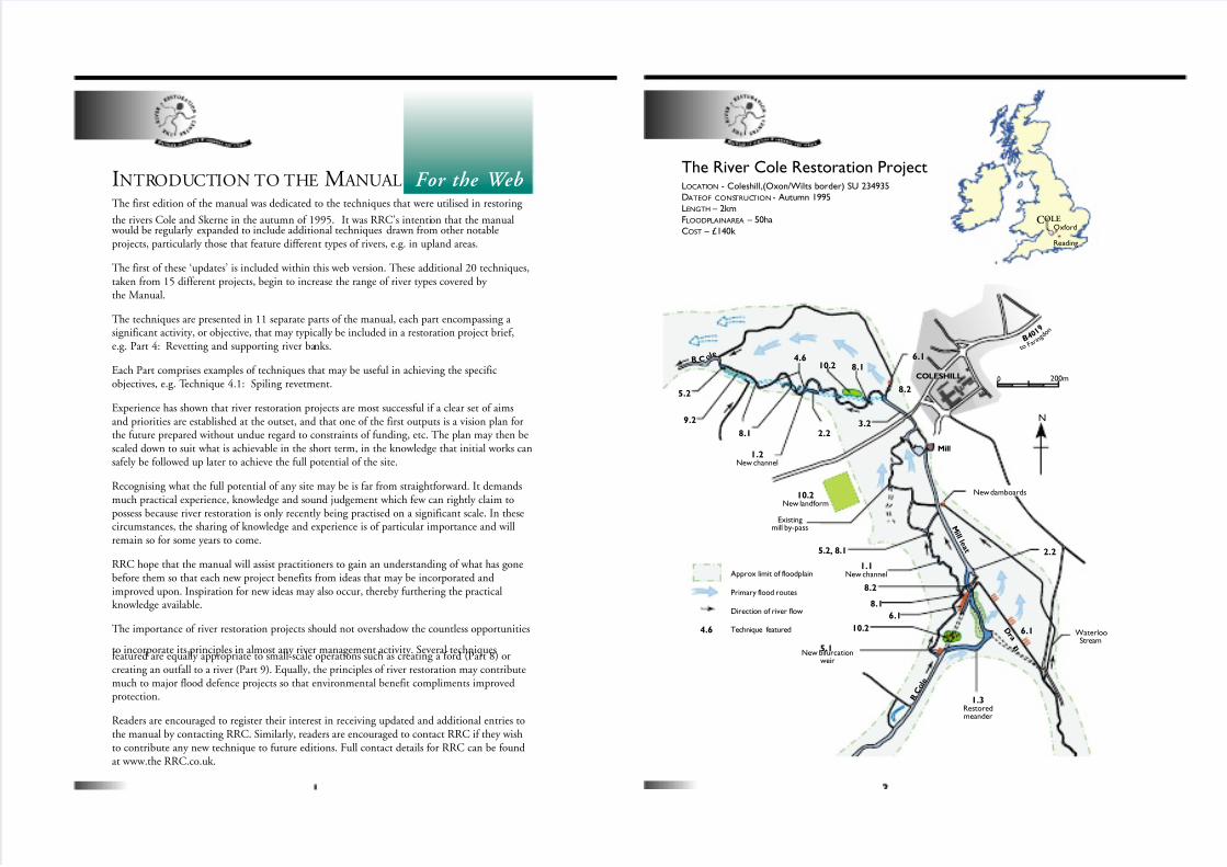
2.25.2, 8.1
10.2New landform
3.2
10.2
2.28.1
9.2
5.2
4.6
8.2
8.1
6.1
8.2
8.1
6.1
10.2
1.1New channelApprox limit of floodplain
Primary flood routes
Direction of river flow
Technique featured
Existingmill by-pass
R C o l e
B 4 0 1 9
t oF a
r i n
g d o n
4.6
The River Cole Restoration ProjectLOCATION - Coleshill,(Oxon/Wilts border) SU 234935DATEOF CONSTRUCTION - Autumn 1995
LENGTH – 2kmFLOODPLAINAREA – 50ha
COST – £140k COLE
Oxford
Reading
7/27/2019 MAN_mod
http://slidepdf.com/reader/full/manmod 2/84
DESCRIPTION OF THE R IVER COLE
AND THE COLE R ESTORATION PROJECTThe river Cole is a tributary of the R.Thames located in the upper part of the catchment. Its headwaters includepart of the large town of Swindon, Wiltshire. The Cole catchment is otherwise rural and is 130km2 in area comprising clay, sand, limestone, and chalk geology. Sediments in the lower reaches, where the river is most modi-fied, are confined to silts and muds. Land use is mixed arable and intensive grassland.
The restoration site is located within 6km of the R.Thames at the village of Coleshill where the floodplain is upto 400m wide and graded at about 1 in 1300. Here the river had been straightened for milling purposes, but morerecently (1970s) further deepened and widened to reduce flooding of arable land.
Restoration works are shown on the accompanying figure. The principle achievement is the creation of a 2kmlong meandering river course that is much smaller in size than the previously enlarged channel. This has restoredmore frequent seasonal flooding to adjacent fields which are now farmed less intensively, supported by CountrysideStewardship.
Full details of the project’s organisation, funding, engineering and scientific monitoring are available from RRC ina variety of formats.
List of techniques featured:
1.1 New meandering channel upstream of mill
1.2 New meandering channel downstream of mill
1.3 Single meander in Mill Leat
2.2 New backwaters in redundant river channels
3 .2 New aquati c l edges
4.6 Short term bank revetments
5.1 Bifurcation weir and spil lway
5.2 Dro p w ei rs in be d
6 .1 Floodpl ain spi llways
8.1 Fords and livestock access
8.2 New c rossings
9.2 New reedbed
10.2 New landforms
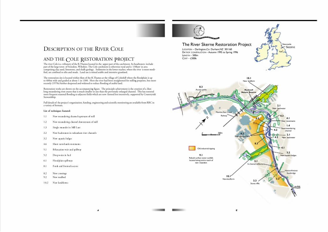
The River Skerne Restoration ProjectLOCATION – Darlington,Co Durham,NZ 301160DATEOF CONSTRUCTION – Autumn 1995 to Spring 1996
LENGTH – 500m
COST – £300k
1.4New meandering
channel
2.1New backwater
2.1New backwater
3.1In channel deflectors
3.2New aquatic ledges
3.3Stone riffle
3.2
4.1New revetments
6.2Reprofiling of land
7.1
4.5
8.3Access paths
9.1Rebuilt surface water outfallslocated along entire reach of
new meanders
10.1New landform
10.1New landform
8.3
4.1
4.3
4.2
4.3
Rockwell
Nature Reserve
Mainline East Coast
Railway
A l b e r t
R o a d
S k e r n e B r i d g
e
to A66R S k e r n
e
Hutton Avenue
footbridge
Old industrial tipping
N
SKERNE
York
Newcastle
0 200m
7/27/2019 MAN_mod
http://slidepdf.com/reader/full/manmod 3/84
DESCRIPTION OF THE R IVER SKERNE
AND THE SKERNE R ESTORATION PROJECTThe River Skerne flows into the R.Tees just south of the town of Darlington, Co. Durham. It has a clay andalluvium based catchment area of 250km2 that includes several small towns, as well as Darlington and a numberof industrial sites that historically polluted the river.
The restoration site is located within a north east suburb of Darlington, Haughton-le-Skerne, where a smalllength of floodplain has survived the historic tipping of industrial waste and urban development that fully occupy it elsewhere. The surviving floodplain is, however, severely disturbed by previous river straightening works andbackfilling, and has many utility services routed through it. The floodplain is less than 1km long, falling at about 1in 1300. Housing and landfill partially encroach onto the floodplain, in places leaving little more than a 100m
width open to public access.
Restoration works are shown on the accompanying figure. The principle achievements are the creation of new meanders on the south side of the old, straight course, and the enhancement of the existing course, both upstreamand downstream of the new meanders, where it proved impossible to re-route the river. A reach of 2 km in all waseither restored or enhanced. Extensive public amenities were incorporated including new paths and landscapeplanting.
Full details of the project’s organisation, funding, engineering and scientific monitoring are available from RRC ina variety of formats.
List of techniques featured:
1.4 New meandering channel
2.1 New backwaters
3.1 In-channel deflectors
3.2 New aquatic ledges
3.3 Stone riffle
4.1 - 4.4 New revetments
4.5 Supporting river banks
6 .2 Re-prof il ing o f l and within meander s
7.1 Floodplain scrapes
8.3 Access paths
9.1 Reb ui lt su rf ac e w at er ou tf all s
10.1 New landforms
1.6 Opening upculverted stream
5.5 Raising river bed levels
3.5 Narrowingover-widened channel
1.5 New meandering channel5.4 Simulated bedrock outcrops8.5 Urban riverside access
3.9 Introducing gravel10.3 Silt removal
4.7 Bank revetment
6.3 Removing floodbanks3.6 Creating a sinuous
low-flow channel
11.1 Diversionof a river valley
3.4 radical re-designto a sinous channel
11.2 Clay lined river
3.8 Creation of on-line bays
7.2 Floodplainwetland mosaic
3.7 Replacingconcrete drain
5.3 Restoringover-deepened bed levels8.4 restoring a ford
1.7 Reconnectingremnant meanders
Bromley
LondonRamsbury
Birmingham
Oxford
Chippenham
Salisbury
Swindon
Doncaster Manchester
Liverpool
Calne
Latimer
Thetford
LouthBethesda
Armagh
New Cumnock
Ayr
Moy
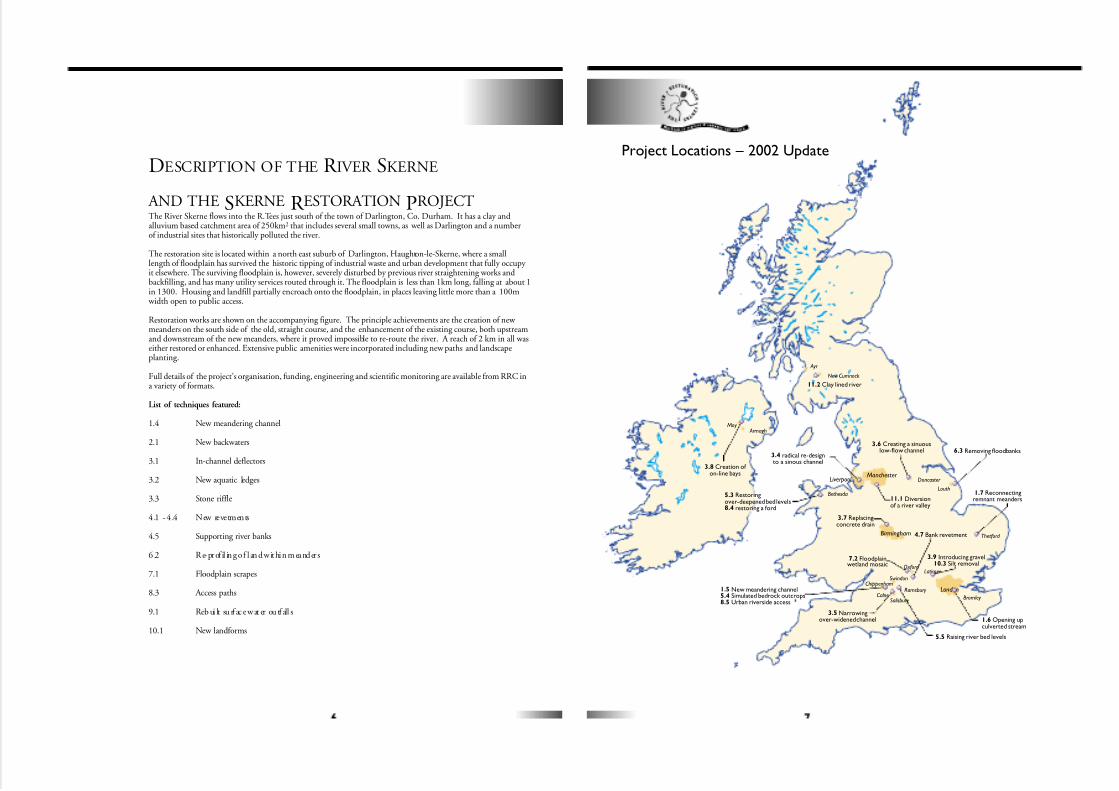
Project Locations – 2002 Update
7/27/2019 MAN_mod
http://slidepdf.com/reader/full/manmod 4/84
LISTING OF THE PROJECTS FEATURED
IN THE 2002 UPDATEThis update of Edition 1, ‘ Restoring the River Cole and River Skerne’, introduces fifteen further projects whererivers have been enhanced, rehabilitated or restored by a variety of organistations and partnerships. Each entry isaccompanied by a contacts list should further information be required.
Project featured: List of techniques featured:
R. Marden, Wi lt s 1 .5 New meandering channe l r ep lacing concre te we ir s5.4 Simulated bedrock outcrops8.5 Urban riverside access
R. Ravensbourne, LB Bromley 1.6 Opening up a culverted stream
R. Little Ouse, Norfolk 1.7 Reconnecting remnant meanders
R. Alt, Merseyside 3.4 Radical re-design from uniform, straight channel to a sinuous,multi-channel river
R . Avon , Wil ts 3 .5 Narrowing of an over-widened channel us ing l ow cost groy nes
R. Dearne, S. Yorkshire 3.6 Creating a sinuous low-flow channel in an over-widened channel
Yardley Brook, Birmingham 3.7 Replacing a concrete drain with a ‘natural’ channel
R. Ta ll , Co. Arma gh 3. 8 Cre at io n o f o n- li ne ba ys
R. Ch es s, Buc ks 3. 9 I ntr od uci ng gra ve l to ina cc es si bl e re ac hes10.3 Cost effective silt removal from an impounded channel
R. Thames, Oxon 4.7 Bank revetment using low steel sheet pil ing and coir rolls
R. Ogwen, Gwynedd 5.3 Restoring and stabilising over-deepened river bed levels8.4 Restoring a ford as a stock and vehicular crossing point
R. Kennet, Wilts 5.5 Rais ing river bed levels
Lon g Ea u, Li nc s 6. 3 Re mov ing a nd s et ti ng b ac k f lo odb anks
R. Thames, Oxon 7.2 F loodplain wetland mosaic
Sugar Brook, Manchester 11.1 Diversion of a river valley
R. Nith, Ayrshire 11.2 Clay lined river
R ESTORING MEANDERS TO
STRAIGHTENED R IVERS
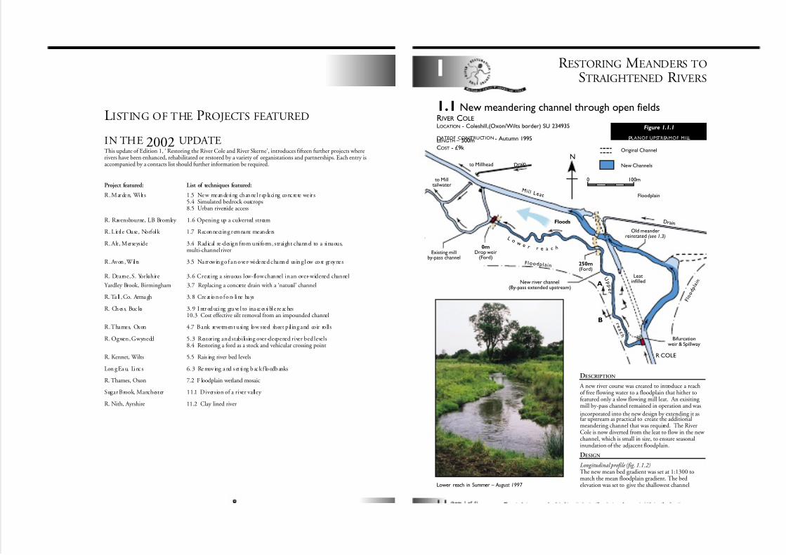
1.1 New meandering channel through open fieldsRIVER COLELOCATION - Coleshill,(Oxon/Wilts border) SU 234935
DATEOF CONSTRUCTION - Autumn 1995LENGTH – 500m
COST - £9k
Floodplain
Existing millby-pass channel
0mDrop weir
(Ford)
250m(Ford)
New river channel(By-pass extended upstream)
to Milltailwater
to Millhead Dr a i n
M i l l L e a t
F lood p l ai n
Leatinfilled
Old meanderreinstated (see 1.3)
Bifurcationweir & Spillway
F l o
o d
p l a
i nA
B
R COLE
D r ai n
L o
w e r r e a c h
U p p
e
r
r e a c h
Floods
0 100m
NNew Channels
Original Channel
DESCRIPTION
A new river course was created to introduce a reachof free flowing water to a floodplain that hither tofeatured only a slow flowing mill leat. An exisiting mill by-pass channel remained in operation and was
incorporated into the new design by extending it asfar upstream as practical to create the additionalmeandering channel that was required. The RiverCole is now diverted from the leat to flow in the new channel, which is small in size, to ensure seasonalinundation of the adjacent floodplain.
DESIGN
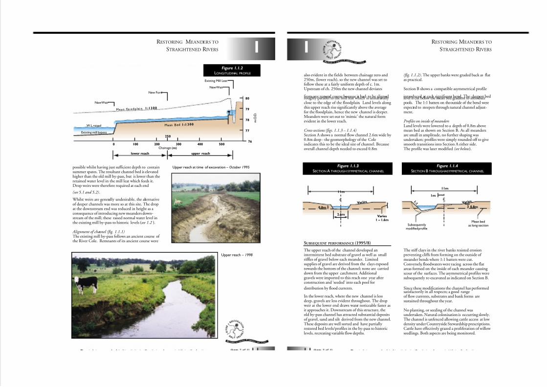
Longitudinal profile (fig. 1.1.2)The new mean bed gradient was set at 1:1300 tomatch the mean floodplain gradient. The bedelevation was set to give the shallowest channelLower reach in Summer – August 1997
1
Figure 1.1.1
PLANOF UPSTREAMOF MILL
7/27/2019 MAN_mod
http://slidepdf.com/reader/full/manmod 5/84
Upper reach – 1998
1
R ESTORING MEANDERS TO
STRAIGHTENED R IVERS
possible whilst having just sufficient depth to containsummer spates. The resultant channel bed is elevatedhigher than the old mill by-pass, but is lower than theretained water level in the mill leat which feeds it.Drop weirs were therefore required at each end
(see 5.1 and 5.2).
Whilst weirs are generally undesirable, the alternativeof deeper channels was more so at this site. The dropat the downstream end was reduced in height as a consequence of introducing new meanders down-stream of the mill; these raised normal water level inthe existing mill by-pass to historic levels (see 1.2 ).
Alignment of channel (fig. 1.1.1)The existing mill by-pass follows an ancient course of the River Cole. Remnants of its ancient course were
0 100
upper reachlower reach
200 300 400 500
Mean Bed 1:1 300
Existing Mill Leat
New Weir
New Ford
New Weir
Mean f lo odp lai n 1:1300
80
79
78
77
76
m . O . D .
W.L.raised
Existing mill bypass
250
Chainage (m)
Figure 1.1.2
LONGITUDINAL PROFILE
Upper reach at time of excavation – October 1995
SUBSEQUENT PERFORMANCE (1995/8)
The upper reach of the channel developed anintermittent bed substrate of gravel as well as smallriffles of gravel below each meander. Limitedsupplies of gravel are derived from the clays exposedtowards the bottom of the channel; none are carrieddown from the upper catchment. Additionalgravels were imported to this reach one year afterconstruction and ‘seeded’ into each pool for
distribution by flood currents.
In the lower reach, where the new channel is lessdeep, gravels are less evident throughout. The drop
weir at the lower end draws water noticeable faster asit approaches it. Downstream of this structure, theold by-pass channel has attracted substantial depositsof gravel, sand and silt derived from the new channel.These deposits are well sorted and have partially restored bed levels/profiles in the by-pass to historiclevels, recreating variable flow depths.
The stiff clays in the river banks resisted erosionpreventing cliffs from forming on the outside of meander bends where 1:1 batters were cut.Conversely, floodwaters were racing across the flatareas formed on the inside of each meander causing scour of the surfaces. The asymmetrical profiles weresubsequently re-excavated as indicated on Section B.
Since these modifications the channel has performedsatisfactorily in all respects; a good rangeof flow currents, substrates and bank forms aresustained throughout the year.
No planting, or seeding of the channel wasundertaken. Natural colonisation is occurring slowly.The channel is unfenced allowing cattle access at low density under Countryside Stewardship prescriptions.Cattle have effectively grazed a proliferation of willow seedlings. Both aspects are being monitored.
also evident in the fields between chainage zero and250m, (lower reach), so the new channel was set tofollow these at a fairly uniform depth of c. 1m.Upstream of ch. 250m the new channel deviates
from any natural course because it had to be alignedroughly parallel to the mill leat which is unnaturally close to the edge of the floodplain. Land levels along this upper reach rise significantly above the averagefor the floodplain, hence the new channel is deeper.Meanders were set out to ‘mimic’ the natural formevident in the lower reach.
Cross-sections (figs. 1.1.3 – 1.1.4)Section A shows a normal flow channel 2.6m wide by 0.8m deep - the geomorphology of the Coleindicates this to be the ideal size of channel. Becauseoverall channel depth needed to exceed 0.8m
(fig. 1.1.2). The upper banks were graded back as flatas practical.
Section B shows a compatible asymmetrical profile
introduced at each significant bend. The deepest bedlevel is cut below the mean bed gradient to introducepools. The 1:1 batters on the outside of the bend wereexpected to steepen through natural channel adjust-ment.
Profiles on inside of meanders Land levels were lowered to a depth of 0.8m abovemean bed as shown on Section B. As all meandersare small in amplitude, no further shaping wasundertaken; profiles were simply rounded off to givesmooth transitions into Section A either side.The profile was later modified (see below ).
R ESTORING MEANDERS TO
STRAIGHTENED R IVERS
1
2.6m
11m
0.8m
Varies1 – 1.6m
Var ie s
Figure 1.1.3
SECTION A THROUGH SYMMETRICAL CHANNEL
11m
1m
0.8m
1 : 1
Subsequentlymodified profile
Mean bedas long section
V a r i e s
Figure 1.1.4
SECTION B THROUGHASYMMETRICAL CHANNEL
7/27/2019 MAN_mod
http://slidepdf.com/reader/full/manmod 6/84
1
R ESTORING MEANDERS TO
STRAIGHTENED R IVERS
The new meandering river course and the restoredmeander in the mill leat (see 1.3) – July 1997
Photo:Environment Agency
R ESTORING MEANDERS TO
STRAIGHTENED R IVERS1
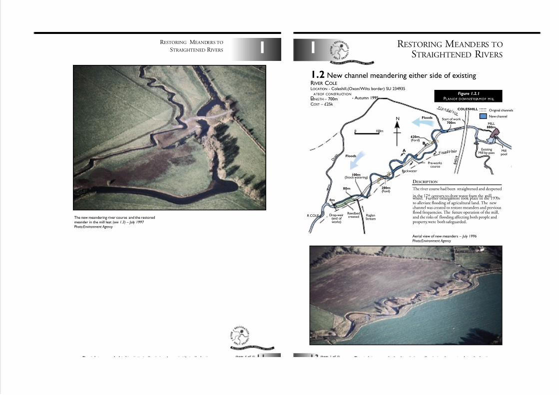
1.2 New channel meandering either side of existingRIVER COLELOCATION - Coleshill,(Oxon/Wilts border) SU 234935
DATEOF CONSTRUCTION
- Autumn 1995LENGTH – 700m
COST – £25k
ExistingMill by-pass
Millpool
MILL880m
B 4 0 1 9
Backwater
Pre-workscourse
Start of work 700m
280m(Ford)
620m(Ford)
ReedbedcreatedDrop-weir
(end of works)
80m
0m
R COLE
A
B
COLESHILL
D r a i n
RaglanStream
F l o odp la in
F l o o d p l a i n
Floods
Floods
100m(Stock watering)
0 100m
NNew channel
Original channels
Aerial view of new meanders – July 1996
Photo:Environment Agency
DESCRIPTION
The river course had been straightened and deepened
in the 17th century to draw water from the mill wheel. Further enlargement took place in the 1970sto alleviate flooding of agricultural land. The new channel was created to restore meanders and previousflood frequencies. The future operation of the mill,and the risks of flooding affecting both people andproperty, were both safeguarded.
Figure 1.2.1
PLANOF DOWNSTREAMOF MILL
7/27/2019 MAN_mod
http://slidepdf.com/reader/full/manmod 7/84
1
R ESTORING MEANDERS TO
STRAIGHTENED R IVERS
DESIGN
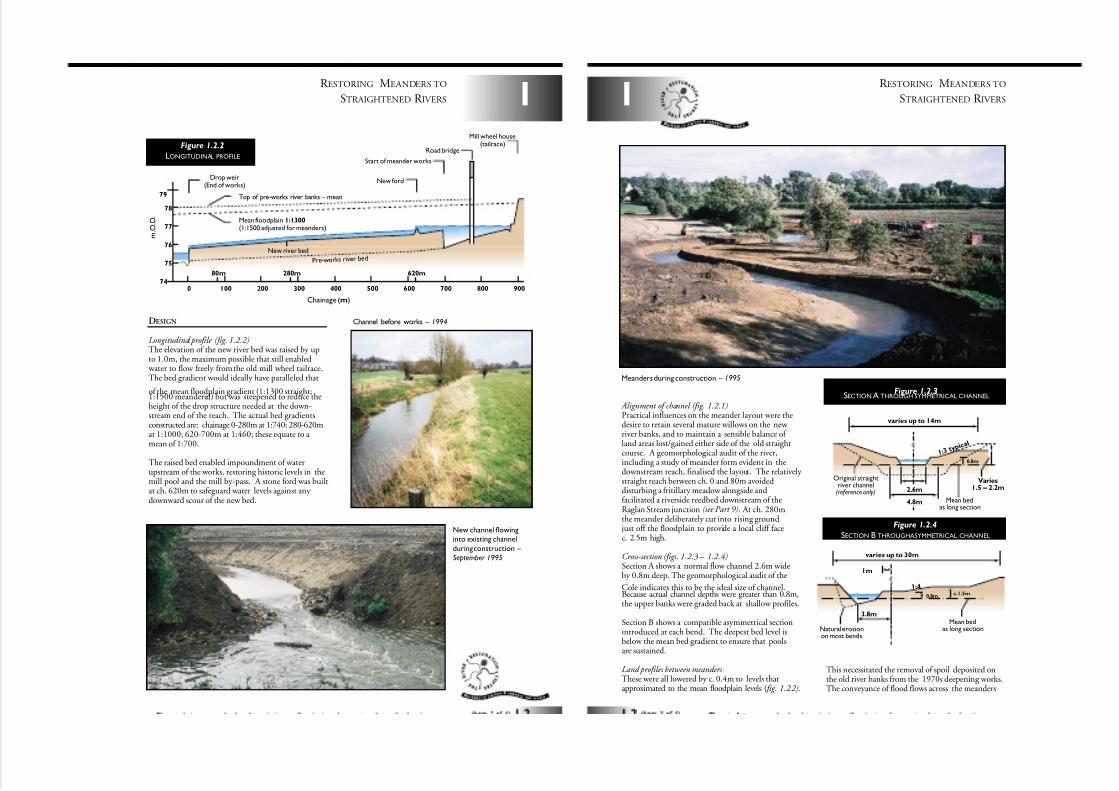
Longitudinal profile (fig. 1.2.2)The elevation of the new river bed was raised by upto 1.0m, the maximum possible that still enabled
water to flow freely from the old mill wheel tailrace.The bed gradient would ideally have paralleled that
of the mean floodplain gradient (1:1300 straight;1:1500 meandered) but was steepened to reduce theheight of the drop structure needed at the down-stream end of the reach. The actual bed gradientsconstructed are: chainage 0-280m at 1:740; 280-620mat 1:1000; 620-700m at 1:460; these equate to a mean of 1:700.
The raised bed enabled impoundment of waterupstream of the works, restoring historic levels in themill pool and the mill by-pass. A stone ford was builtat ch. 620m to safeguard water levels against any downward scour of the new bed.
074
75
76
77
78
79
100 200
280m80m 620m
300 400 500 600 700 800 900
Top of pre-works river banks – mean
Mean floodplain 1:1300(1:1500 adjusted for meanders)
Pre-work s river bed
Drop weir(End of works)
New ford
Start of meander works
Road bridge
Mill wheel house(tailrace)
New river bed
Chainage (m)
m . O . D .
Figure 1.2.2
LONGITUDINAL PROFILE
New channel flowinginto existing channel
during construction –
September 1995
Channel before works – 1994
Alignment of channel (fig. 1.2.1)Practical influences on the meander layout were thedesire to retain several mature willows on the new river banks, and to maintain a sensible balance of land areas lost/gained either side of the old straightcourse. A geomorphological audit of the river,including a study of meander form evident in thedownstream reach, finalised the layout. The relatively straight reach between ch. 0 and 80m avoideddisturbing a fritillary meadow alongside andfacilitated a riverside reedbed downstream of theRaglan Stream junction (see Part 9). At ch. 280mthe meander deliberately cut into rising ground
just off the floodplain to provide a local cliff facec. 2.5m high.
Cross-section (figs. 1.2.3 – 1.2.4)Section A shows a normal flow channel 2.6m wideby 0.8m deep. The geomorphological audit of the
Cole indicates this to be the ideal size of channel.Because actual channel depths were greater than 0.8m,the upper banks were graded back at shallow profiles.
Section B shows a compatible asymmetrical sectionintroduced at each bend. The deepest bed level isbelow the mean bed gradient to ensure that poolsare sustained.
Land profiles between meanders These were all lowered by c. 0.4m to levels thatapproximated to the mean floodplain levels ( fig. 1.2.2).
R ESTORING MEANDERS TO
STRAIGHTENED R IVERS
2.6m
4.8m
0.8m
Varies1.5 – 2.2m
1 : 3t y p i
c a l
varies up to 14m
Original straightriver channel(reference only)
Mean bedas long section
Figure 1.2.3SECTION A THROUGH SYMMETRICAL CHANNEL
Mean bedas long sectionNatural erosion
on most bends
varies up to 30m
1m
0.8m
3.8m
c.1.5m
1 : 4
Figure 1.2.4
SECTION B THROUGHASYMMETRICAL CHANNEL
1
Meanders during construction – 1995
This necessitated the removal of spoil deposited onthe old river banks from the 1970s deepening works.The conveyance of flood flows across the meanders
7/27/2019 MAN_mod
http://slidepdf.com/reader/full/manmod 8/84
1
R ESTORING MEANDERS TO
STRAIGHTENED R IVERS
proved to be important in achieving the necessary hydraulic safeguards during 1 in 100 year floodconditions.
The old straight channel located within these areas
was largely backfilled, although not completely (see Parts 2 and 8 for details of backwaters, fords,stock watering points, etc that were incorporated).
SUBSEQUENT PERFORMANCE 1995/8
Spates of floodwater immediately following comple-tion of the new channel led to rapid and extensivereshaping of the channel. Cliffs were eroded, pools
were scoured and gravel riffles and sandy shoalsdeposited, all creating desirable natural features withinthe reach. Excess sediments built up immediately
downstream of the works, helping to restore a furtherreach of the original over-deep channel. Since theseinitial adjustments, subsequent spates have satisfacto-rily sustained the regime described but at a muchlower rate of change. Intervention has been limited to
further flattening of the profile of the inside of thesouth side bend at ch. 280m. The river is largely unvegetated after two summers, although marginalvegetation is becoming established. A wide rangeof soil types are exposed in the channel and theseaccount for the diversity of features that are now evident.
Diverse new channel – Two years after construction.
– March 1997
Natural cliff formation post works – March 1997
R ESTORING MEANDERS TO
STRAIGHTENED R IVERS1
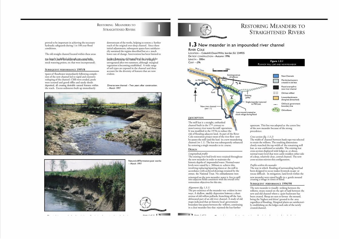
1.3 New meander in an impounded river channelRIVER COLELOCATION – Coleshill,Oxon/Wilts border,SU 234935
DATEOF CONSTRUCTION – Autumn 1996LENGTH – 300m
COST – £9k
DESCRIPTION
The mill leat is a straight, embankedchannel built in the 17th century tostore/convey river water for mill operations.It was modified in the 1970s to reduce therisk of flooding adjacent land. As part of the RiverCole restoration project most of the river flow now by-passes the mill (and the leat) in a new meandering channel (see 1.1). The leat was subsequently enhancedby restoring a single meander to its course.
DESIGN
Longitudinal profile The existing river bed levels were retained throughoutthe new meander in order to maintain thehistoric depths of impounded water. Normal waterlevels were raised by c. 300mm to achieve this,involving replacing/repairing sluices at the mill inaccordance with archived drawings retained by theowner, the National Trust. No embankments were
reinstated on the new meander; water is free to spillinto adjacent fields consistent with the overall riverrestoration objectives for this site.
Alignment (fig. 1.3.1)The pre-existence of the meander was evident in two
ways. A shallow, muddy depression between a shortavenue of old willow pollards, branching off the leat,delineated part of an old river channel. A study of oldmaps indicated that an historic local governmentboundary line passes between the willows, continuing in a clear meander line that rejoined the leat further
upstream. This line was adopted as the centre lineof the new meander because of the strong precedence.
Cross-section (fig. 1.3.2)The width of channel between bank tops was selectedto retain the willows. The resulting dimensionsclosely matched the top width of the remaining millleat, so was confirmed as suitable. The existing leatcross-section displayed wide ledges at, or about,normal water level that were cattle trodden either sideof a deep, relatively clear, central channel. The new cross-section mirrors this configuration.
Profiles within the meander The way in which flooding of surrounding land hadbeen designed to occur makes livestock escape orrescue difficult. In mitigation, land levels within the
new meander were raised locally in a gentle moundcreating a refuge in times of flood.
SUBSEQUENT PERFORMANCE 1996/98
The new meander is visually striking between the willows; swans nested on the spit of land between thenew and old channel where a quiet backwater hasbeen created. Sheep are seen to favour the mound,being the ‘highest and driest’ ground in the area regardless of flooding. Marginal plants are satisfactori-ly establishing on the ledges each side of the newly created channel.
0 100m
N
to Mill By-pass
Ford
Existing avenueof willows
New river channel(see 1.1)
M i l l L e a t
Single meander restoredto Mill Leat
Low mound created asstock refuge during flood
ExistinggulleyA
A
D r ai n
New Channels
Marshy backwaterscreated in old leat
Flood overspill tonew river channel
Old leat infilled
Low embankmentsalong leat (breached)
Old local governmentboundary line
Old willows
Figure 1.3.1
PLANOF MILL LEAT AND NEWMEANDER
7/27/2019 MAN_mod
http://slidepdf.com/reader/full/manmod 9/84
1
R ESTORING MEANDERS TO
STRAIGHTENED R IVERS
Remnant of meander – pre-works
– January 1996
(shallow water held temporarilyafter heavy rain/flooding).
Re-excavated meander
– Autumn 1997
0 3.5 7 11.5 1476
78
80
Ledges cut ator just below water level
Old willows retained(partly pollarded)
Old spoil deposits breachedto allow flood overspill onto
adjacent field (79.30m)
Water levelretained in leat(78.90m)
m . O . D .
Existing bed levelof leat retained (77.40m)
Width (m)
Figure 1.3.2
SECTION OF NEW MEANDERAT A – A
R ESTORING MEANDERS TO
STRAIGHTENED R IVERS1
Figure 1.4.1
PLANOF NEWMEANDERS
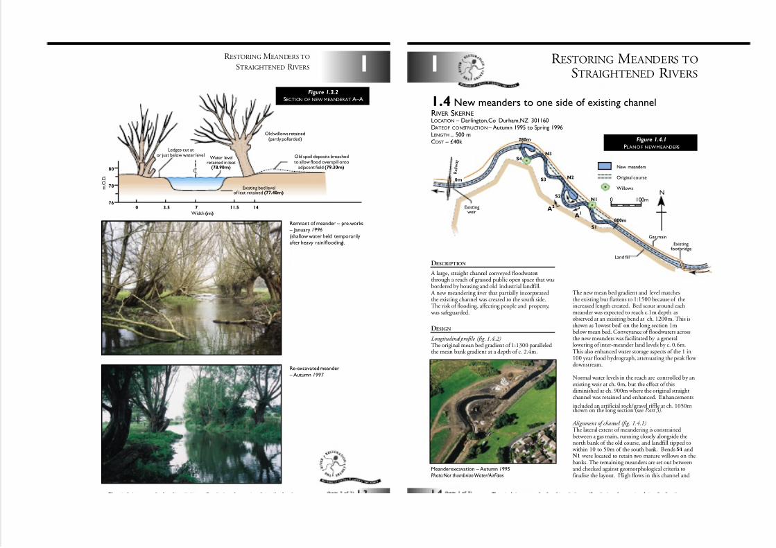
DESCRIPTION
A large, straight channel conveyed floodwatersthrough a reach of grassed public open space that wasbordered by housing and old industrial landfill.
A new meandering river that partially incorporatedthe existing channel was created to the south side.The risk of flooding, affecting people and property,
was safeguarded.
DESIGN
Longitudinal profile (fig. 1.4.2)The original mean bed gradient of 1:1300 paralleledthe mean bank gradient at a depth of c. 2.4m.
N3
N2
S2
S1
S3
S4
Existingweir
Existingfootbridge
Gas main
Land fill
N1
800m
280m
0m
A2
A1
R a
i l w a y
New meanders
Original course
Willows
0 100m
N
1.4 New meanders to one side of existing channelRIVER SKERNELOCATION – Darlington,Co Durham,NZ 301160DATEOF CONSTRUCTION – Autumn 1995 to Spring 1996
LENGTH–
500 mCOST – £40k
Meander excavation – Autumn 1995
Photo:Nor thumbrian Water/AirFotos
The new mean bed gradient and level matchesthe existing but flattens to 1:1500 because of theincreased length created. Bed scour around eachmeander was expected to reach c.1m depth asobserved at an exisiting bend at ch. 1200m. This isshown as ‘lowest bed’ on the long section 1mbelow mean bed. Conveyance of floodwaters acrossthe new meanders was facilitated by a generallowering of inter-meander land levels by c. 0.6m.This also enhanced water storage aspects of the 1 in100 year flood hydrograph, attenuating the peak flow downstream.
Normal water levels in the reach are controlled by anexisting weir at ch. 0m, but the effect of thisdiminished at ch. 900m where the original straightchannel was retained and enhanced. Enhancements
included an artificial rock/gravel riffle at ch. 1050mshown on the long section (see Part 3).
Alignment of channel (fig. 1.4.1)The lateral extent of meandering is constrainedbetween a gas main, running closely alongside thenorth bank of the old course, and landfill tipped to
within 10 to 50m of the south bank. Bends S4 andN1 were located to retain two mature willows on thebanks. The remaining meanders are set out betweenand checked against geomorphological criteria tofinalise the layout. High flows in this channel and
7/27/2019 MAN_mod
http://slidepdf.com/reader/full/manmod 10/84
1
R ESTORING MEANDERS TO
STRAIGHTENED R IVERS
other constraints precluded any possibility of ‘mirror-
ing’ historic meander patterns that were sustained by entirely different hydraulic criteria.
Cross-sections (fig. 1.4.3)Because of continuously varying vertical depthsdescribed for the longitudinal profile, the designneeded to be simplified. Two sections (symmetricaland asymmetrical) were developed based on meandepth (1.8m) and mean top width (18m). Theseapplied to two points only on each meander - inter-mediate profiles required a continuous transitionbetween them. The asymmetrical section allows for1m of scour at each bend described above.
A variation of the pair of sections shown was
developed for bends S1 and S4. A horizontal ledgeat normal water level was incorporated aroundthe inside of each to simulate the effects of naturalshoaling.
Profiles within meanders (see 6.2 and 2.1) As well as the general lowering of land levelsdescribed above, considerable profiling was specifiedto ensure inundation in time of flood was progressivefrom the downstream leg back towards the start of each meander. Similarly, special consideration wasneeded to ensure the safe ‘submergence’ of backwaterfeatures prior to general overbank flow. The safety of
0 200 400 600 800 1000 1200 1400
39
40
41
42
43
m . .
O . D .
Existing New meander Existing
E xis ting mean bank 1:1500 (1:1300 s traigh t )
Mean bed 1:1500
Lo wes t bed
Pro f ile be tween meanders
Existingfootbridge
Existing bed(lowest bed)
New riffleExisting weir
Chainage (m)
5.4m
18m nominal top width at 1.8m depthTransitional profilesat inner meander
1.8m nominal
1m
1m
Varies(2.4m typical) 1
: 1
1: 3 .5 1 : 5
Mean bed(see long section)
Existing ground level
Existingground
level
Varies(0.6m typical)
Section A1 (symmetrical)
Section A2 (asymmetrical)
Setting out points (3 no.)
Figure 1.4.2
LONGITUDINAL PROFILE
Figure 1.4.3
SECTIONTHROUGH NEW MEANDERS
people during rising floods is of particular importanceat this urban location. Exceptionally, land withinbend N1 could not be significantly re-profiled asa high voltage cable passes underneath.
SUBSEQUENT PERFORMANCE 1995/8
The newly meandered channel has proved to bestable under frequently occurring flood conditions.The most vulnerable banks, located where bends areincorporated into the backfilled course, are supported
by revetments (see Part 4 ), but elsewhere theindigenous clays have resisted erosion. Sands, silts andmud have deposited as shoals where eddy currentsarise around the inner margins of bends and the
deeper pools created around the outside appearself-sustaining. Diverse flora and fauna have rapidly colonised the many different features of the new course and local people enjoy relatively safe accessto the waters edge.
Looking downstream
towards large backwater – February 1997
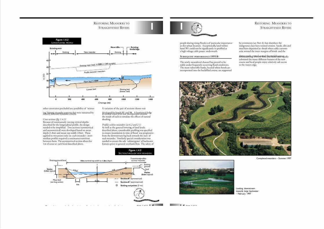
Completed meanders – Summer 1997
R ESTORING MEANDERS TO
STRAIGHTENED R IVERS
1
7/27/2019 MAN_mod
http://slidepdf.com/reader/full/manmod 11/84
R ESTORING MEANDERS TO
STRAIGHTENED R IVERS
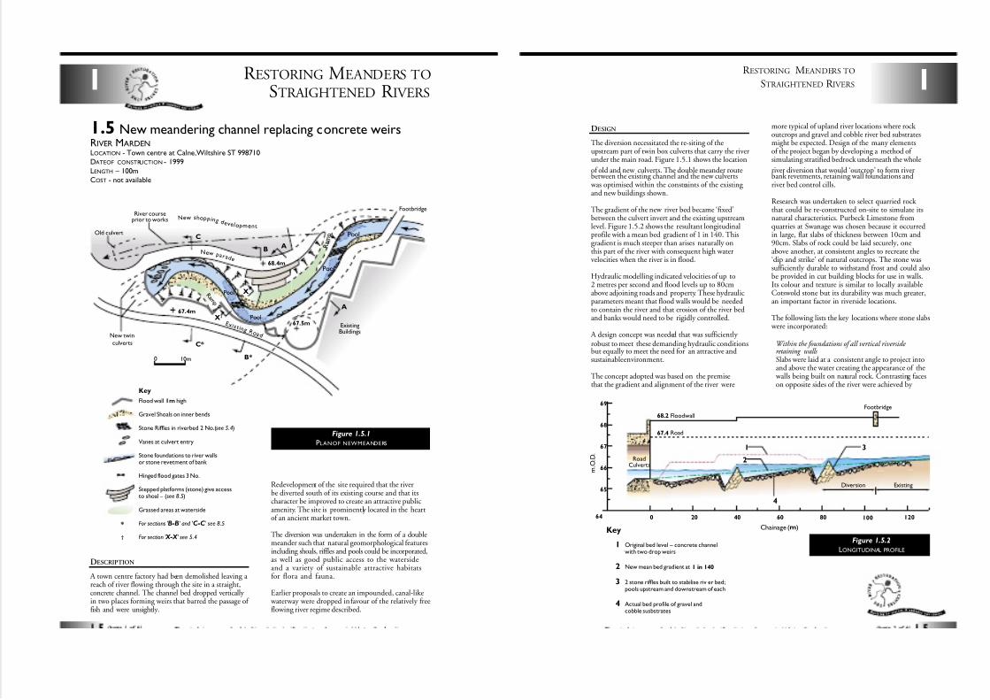
1.5 New meandering channel replacing concrete weirsRIVER MARDENLOCATION - Town centre at Calne,Wiltshire ST 998710
DATEOF CONSTRUCTION - 1999
LENGTH – 100m
COST - not available
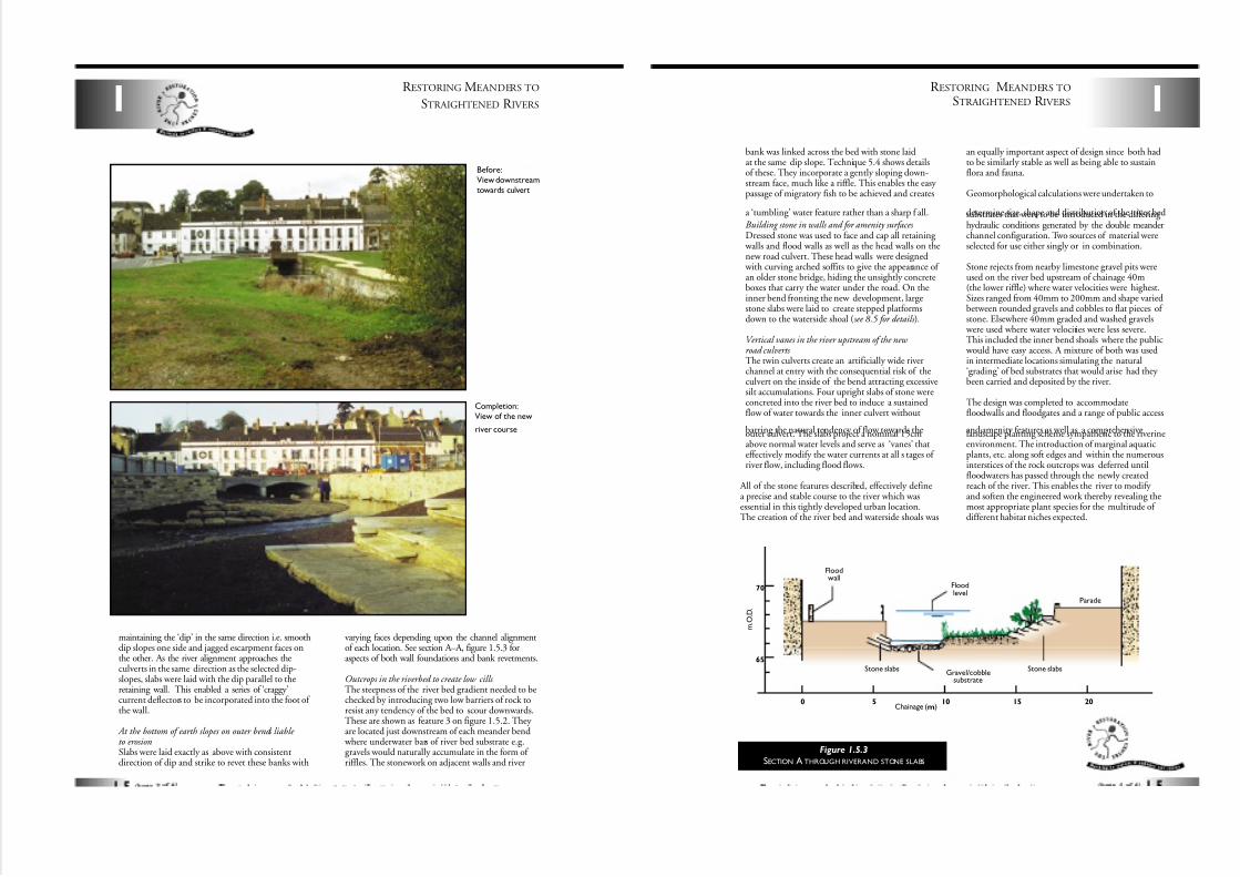
DESCRIPTION
A town centre factory had been demolished leaving a reach of river flowing through the site in a straight,concrete channel. The channel bed dropped vertically in two places forming weirs that barred the passage of fish and were unsightly.
Redevelopment of the site required that the riverbe diverted south of its existing course and that itscharacter be improved to create an attractive publicamenity. The site is prominently located in the heartof an ancient market town.
The diversion was undertaken in the form of a doublemeander such that natural geomorphological featuresincluding shoals, riffles and pools could be incorporated,as well as good public access to the watersideand a variety of sustainable attractive habitatsfor flora and fauna.
Earlier proposals to create an impounded, canal-like waterway were dropped in favour of the relatively freeflowing river regime described.
1
River courseprior to works
Old culvert
ExistingBuildings
R a m p
R a m p
Pool
Pool
Pool
Pool
New twin
culverts
Footbridge
Ne w shop p i n g d e v e l opmen t
Ne w p a r a d e
E x i s t i n g R o a d
0 10m
BA
A
C
C*
X†
X
67.4m
67.5m
B*
68.4m
Key
Flood wall 1m high
Gravel Shoals on inner bends
Stone Riffles in riverbed 2 No.(see 5.4)
Vanes at culvert entry
Stone foundations to river wallsor stone revetment of bank
Hinged flood gates 3 No.
Stepped platforms (stone) give accessto shoal – (see 8.5)
Grassed areas at waterside
For sections 'B-B' and 'C-C' see 8.5
For section ' X-X ' see 5.4
*
†
Figure 1.5.1
PLANOF NEWMEANDERS
1
R ESTORING MEANDERS TO
STRAIGHTENED R IVERS
DESIGN
The diversion necessitated the re-siting of theupstream part of twin box culverts that carry the riverunder the main road. Figure 1.5.1 shows the location
of old and new culverts. The double meander routebetween the existing channel and the new culverts
was optimised within the constraints of the existing and new buildings shown.
The gradient of the new river bed became ‘fixed’between the culvert invert and the existing upstreamlevel. Figure 1.5.2 shows the resultant longitudinalprofile with a mean bed gradient of 1 in 140. Thisgradient is much steeper than arises naturally onthis part of the river with consequent high watervelocities when the river is in flood.
Hydraulic modelling indicated velocities of up to2 metres per second and flood levels up to 80cmabove adjoining roads and property. These hydraulicparameters meant that flood walls would be neededto contain the river and that erosion of the river bedand banks would need to be rigidly controlled.
A design concept was needed that was sufficiently robust to meet these demanding hydraulic conditionsbut equally to meet the need for an attractive andsustainable environment.
The concept adopted was based on the premisethat the gradient and alignment of the river were
more typical of upland river locations where rock outcrops and gravel and cobble river bed substratesmight be expected. Design of the many elementsof the project began by developing a method of simulating stratified bedrock underneath the whole
river diversion that would ‘outcrop’ to form riverbank revetments, retaining wall foundations andriver bed control cills.
Research was undertaken to select quarried rock that could be re-constructed on-site to simulate itsnatural characteristics. Purbeck Limestone fromquarries at Swanage was chosen because it occurredin large, flat slabs of thickness between 10cm and90cm. Slabs of rock could be laid securely, oneabove another, at consistent angles to recreate the‘dip and strike’ of natural outcrops. The stone wassufficiently durable to withstand frost and could alsobe provided in cut building blocks for use in walls.Its colour and texture is similar to locally availableCotswold stone but its durability was much greater,an important factor in riverside locations.
The following lists the key locations where stone slabs were incorporated:
Within the foundations of all vertical riverside retaining walls Slabs were laid at a consistent angle to project intoand above the water creating the appearance of the
walls being built on natural rock. Contrasting faceson opposite sides of the river were achieved by
1
2
3
4
Key
Original bed level – concrete channelwith two drop weirs
New mean bed gradient at 1 in 140
2 stone riffles built to stabilise riv er bed;pools upstream and downstream of each
Actual bed profile of gravel andcobble susbstrates
0 20 40 60 80 100 120
Chainage (m)
64
65
66
67
69
68
1 3
2
4
Footbridge
68.2 Floodwall
67.4 Road
Diversion Existing
RoadCulverts
m . O . D .
Figure 1.5.2
LONGITUDINAL PROFILE
7/27/2019 MAN_mod
http://slidepdf.com/reader/full/manmod 12/84
maintaining the ‘dip’ in the same direction i.e. smoothdip slopes one side and jagged escarpment faces onthe other. As the river alignment approaches theculverts in the same direction as the selected dip-slopes, slabs were laid with the dip parallel to theretaining wall. This enabled a series of ‘craggy’current deflectors to be incorporated into the foot of the wall.
At the bottom of earth slopes on outer bends liable to erosionSlabs were laid exactly as above with consistentdirection of dip and strike to revet these banks with
varying faces depending upon the channel alignmentof each location. See section A–A, figure 1.5.3 foraspects of both wall foundations and bank revetments.
Outcrops in the riverbed to create low cills The steepness of the river bed gradient needed to bechecked by introducing two low barriers of rock toresist any tendency of the bed to scour downwards.These are shown as feature 3 on figure 1.5.2. They are located just downstream of each meander bend
where underwater bars of river bed substrate e.g.gravels would naturally accumulate in the form of riffles. The stonework on adjacent walls and river
R ESTORING MEANDERS TO
STRAIGHTENED R IVERS
1
Before:View downstreamtowards culvert
Completion:View of the new
river course
bank was linked across the bed with stone laidat the same dip slope. Technique 5.4 shows detailsof these. They incorporate a gently sloping down-stream face, much like a riffle. This enables the easy passage of migratory fish to be achieved and creates
a ‘tumbling’ water feature rather than a sharp f all.
Building stone in walls and for amenity surfaces Dressed stone was used to face and cap all retaining
walls and flood walls as well as the head walls on thenew road culvert. These head walls were designed
with curving arched soffits to give the appearance of an older stone bridge, hiding the unsightly concreteboxes that carry the water under the road. On theinner bend fronting the new development, largestone slabs were laid to create stepped platformsdown to the waterside shoal (see 8.5 for details ).
Vertical vanes in the river upstream of the new road culverts The twin culverts create an artificially wide riverchannel at entry with the consequential risk of theculvert on the inside of the bend attracting excessivesilt accumulations. Four upright slabs of stone wereconcreted into the river bed to induce a sustainedflow of water towards the inner culvert without
barring the natural tendency of flow towards theouter culvert. The slabs project a nominal 15cmabove normal water levels and serve as ‘vanes’ thateffectively modify the water currents at all s tages of river flow, including flood flows.
All of the stone features described, effectively definea precise and stable course to the river which wasessential in this tightly developed urban location.The creation of the river bed and waterside shoals was
an equally important aspect of design since both hadto be similarly stable as well as being able to sustainflora and fauna.
Geomorphological calculations were undertaken to
determine size, shape and distribution of the river bedsubstrates that were to be introduced in the differing hydraulic conditions generated by the double meanderchannel configuration. Two sources of material wereselected for use either singly or in combination.
Stone rejects from nearby limestone gravel pits wereused on the river bed upstream of chainage 40m(the lower riffle) where water velocities were highest.Sizes ranged from 40mm to 200mm and shape variedbetween rounded gravels and cobbles to flat pieces of stone. Elsewhere 40mm graded and washed gravels
were used where water velocities were less severe.This included the inner bend shoals where the public
would have easy access. A mixture of both was usedin intermediate locations simulating the natural‘grading’ of bed substrates that would arise had they been carried and deposited by the river.
The design was completed to accommodatefloodwalls and floodgates and a range of public access
and amenity features as well as a comprehensivelandscape planting scheme sympathetic to the riverineenvironment. The introduction of marginal aquaticplants, etc. along soft edges and within the numerousinterstices of the rock outcrops was deferred untilfloodwaters has passed through the newly createdreach of the river. This enables the river to modify and soften the engineered work thereby revealing themost appropriate plant species for the multitude of different habitat niches expected.
1
R ESTORING MEANDERS TO
STRAIGHTENED R IVERS
0 5 10 15 20Chainage (m)
65
70
Parade
Floodwall
Floodlevel
Stone slabsStone slabsGravel/cobble
substrate
m . O . D .
Figure 1.5.3
SECTION A THROUGH RIVERAND STONE SLABS
7/27/2019 MAN_mod
http://slidepdf.com/reader/full/manmod 13/84
R ESTORING MEANDERS TO
STRAIGHTENED R IVERS1
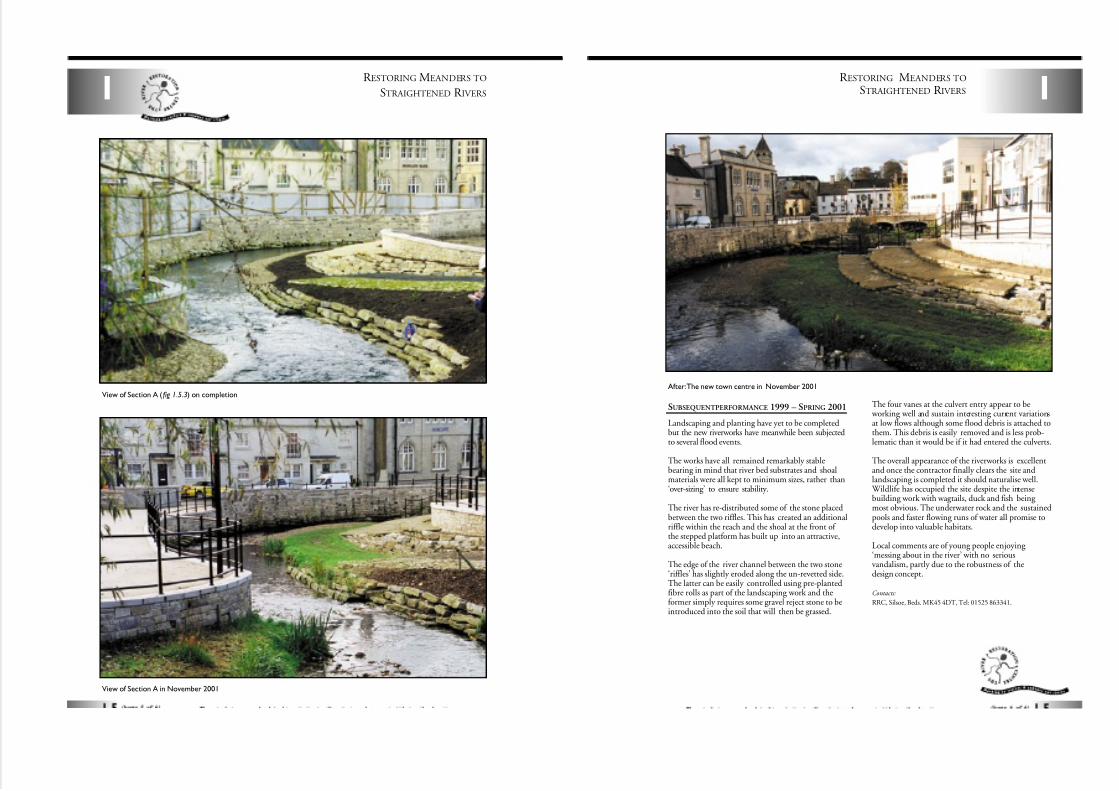
View of Section A in November 2001
View of Section A ( fig 1.5.3) on completion
1
R ESTORING MEANDERS TO
STRAIGHTENED R IVERS
SUBSEQUENT PERFORMANCE 1999 – SPRING 2001
Landscaping and planting have yet to be completedbut the new riverworks have meanwhile been subjectedto several flood events.
The works have all remained remarkably stablebearing in mind that river bed substrates and shoalmaterials were all kept to minimum sizes, rather than‘over-sizing’ to ensure stability.
The river has re-distributed some of the stone placedbetween the two riffles. This has created an additionalriffle within the reach and the shoal at the front of the stepped platform has built up into an attractive,accessible beach.
The edge of the river channel between the two stone‘riffles’ has slightly eroded along the un-revetted side.The latter can be easily controlled using pre-plantedfibre rolls as part of the landscaping work and theformer simply requires some gravel reject stone to beintroduced into the soil that will then be grassed.
The four vanes at the culvert entry appear to be working well and sustain interesting current variationsat low flows although some flood debris is attached tothem. This debris is easily removed and is less prob-lematic than it would be if it had entered the culverts.
The overall appearance of the riverworks is excellentand once the contractor finally clears the site andlandscaping is completed it should naturalise well.
Wildlife has occupied the site despite the intensebuilding work with wagtails, duck and fish being most obvious. The underwater rock and the sustainedpools and faster flowing runs of water all promise todevelop into valuable habitats.
Local comments are of young people enjoying ‘messing about in the river’ with no seriousvandalism, partly due to the robustness of thedesign concept.
Contacts:
RRC, Silsoe, Beds. MK45 4DT, Tel: 01525 863341.
After:The new town centre in November 2001
7/27/2019 MAN_mod
http://slidepdf.com/reader/full/manmod 14/84
R ESTORING MEANDERS TO
STRAIGHTENED R IVERS
1.6 Opening up a culverted streamRIVER RAVENSBOURNELOCATION - Norman Park, Bromley TQ 412674
DATE OF CONSTRUCTION - March to June 2000LENGTH – 300m
COST - £127,000
1
Timber footbridge5m span,1.5m widewith deck at existing
ground level
Low level 'clapper' footbridgewith deck level 700mm above
bed channel.Approach paths in hoggin
at 1:8 gradient
Existing culvertremoved
New inletto existing culvert
Existing culvertto be retained
Native shrubplanting at outlet
Existing culvertto be removed
Native shrubplanting at inlet
New outletto existing culvert
Existing gratingand trash screento be removed
Existing culvert retained.End plugged with concreteand 300mm dia concretepipe inserted to provide
discharge for existingland drain connections,
and flood storage
A
A
B1
B1
B2
B2
N
Figure 1.6.1
PLANOF NEWCHANNEL
DESCRIPTION
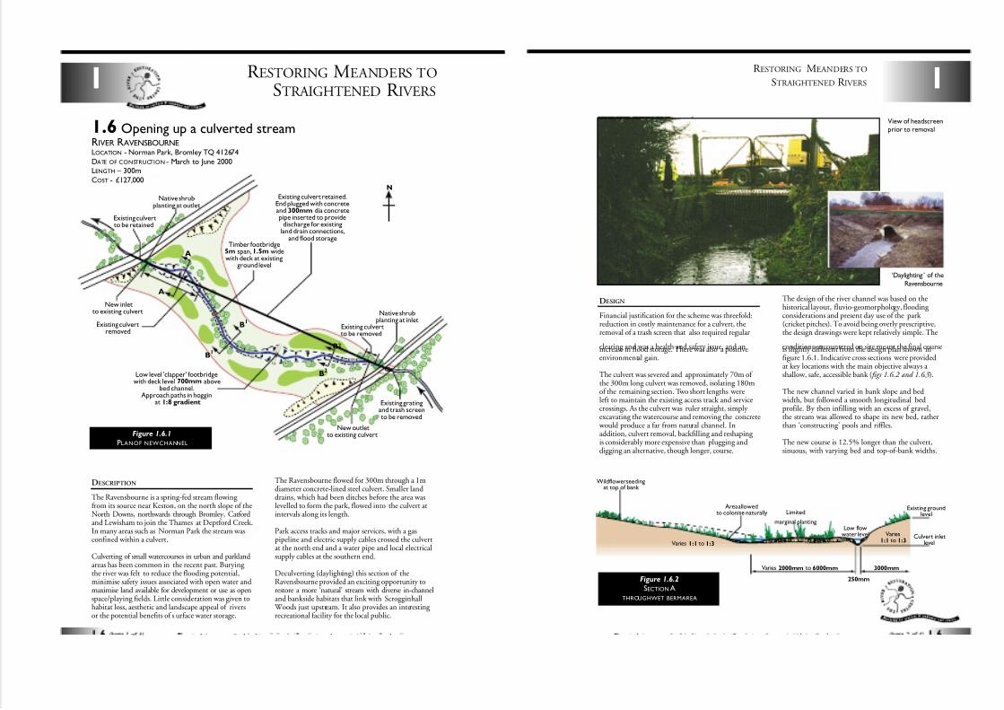
The Ravensbourne is a spring-fed stream flowing from its source near Keston, on the north slope of theNorth Downs, northwards through Bromley, Catfordand Lewisham to join the Thames at Deptford Creek.In many areas such as Norman Park the stream wasconfined within a culvert.
Culverting of small watercourses in urban and parklandareas has been common in the recent past. Burying the river was felt to reduce the flooding potential,minimise safety issues associated with open water andmaximise land available for development or use as openspace/playing fields. Little consideration was given tohabitat loss, aesthetic and landscape appeal of riversor the potential benefits of s urface water storage.
The Ravensbourne flowed for 300m through a 1mdiameter concrete-lined steel culvert. Smaller landdrains, which had been ditches before the area waslevelled to form the park, flowed into the culvert atintervals along its length.
Park access tracks and major services, with a gaspipeline and electric supply cables crossed the culvertat the north end and a water pipe and local electricalsupply cables at the southern end.
Deculverting (daylighting) this section of theRavensbourne provided an exciting opportunity torestore a more ‘natural’ stream with diverse in-channeland bankside habitats that link with Scrogginhall
Woods just upstream. It also provides an interesting recreational facility for the local public.
1
R ESTORING MEANDERS TO
STRAIGHTENED R IVERS
DESIGN
Financial justification for the scheme was threefold:reduction in costly maintenance for a culvert, theremoval of a trash screen that also required regular
clearing and was a health and safety issue, and anincrease in flood storage. There was also a positiveenvironmental gain.
The culvert was severed and approximately 70m of the 300m long culvert was removed, isolating 180mof the remaining section. Two short lengths wereleft to maintain the existing access track and servicecrossings. As the culvert was ruler straight, simply excavating the watercourse and removing the concrete
would produce a far from natural channel. Inaddition, culvert removal, backfilling and reshaping is considerably more expensive than plugging anddigging an alternative, though longer, course.
The design of the river channel was based on thehistorical layout, fluvio-geomorphology, flooding considerations and present day use of the park (cricket pitches). To avoid being overly prescriptive,the design drawings were kept relatively simple. The
conditions encountered on site meant the final courseis slightly different from the design plan shown infigure 1.6.1. Indicative cross sections were providedat key locations with the main objective always a shallow, safe, accessible bank ( figs 1.6.2 and 1.6.3).
The new channel varied in bank slope and bed width, but followed a smooth longitudinal bedprofile. By then infilling with an excess of gravel,the stream was allowed to shape its new bed, ratherthan ‘constructing’ pools and riffles.
The new course is 12.5% longer than the culvert,sinuous, with varying bed and top-of-bank widths.
Area allowedto colonise naturally
Wildflower seedingat top of bank
Low flowwater level
Existing groundlevel
Culvert inletlevel
Limited
marginal planting
Varies 1:1 to 1:3
Varies1:1 to 1:3
Varies 2000mm to 6000mm 3000mm
250mmFigure 1.6.2
SECTION A
THROUGHWET BERMAREA
View of headscreenprior to removal
‘Daylighting ’ of the
Ravensbourne
7/27/2019 MAN_mod
http://slidepdf.com/reader/full/manmod 15/84
R ESTORING MEANDERS TO
STRAIGHTENED R IVERS1
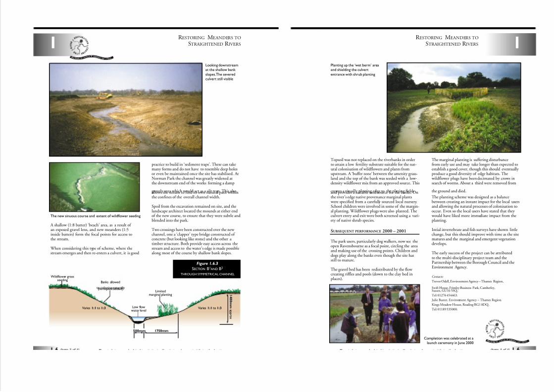
A shallow (1:8 batter) ‘beach’ area, as a result of an exposed gravel lens, and new meanders (1:5inside batters) form the focal points for access tothe stream.
When considering this type of scheme, where thestream emerges and then re-enters a culvert, it is good
practice to build in ‘sediment traps’. These can takemany forms and do not have to resemble deep holesor even be maintained once the site has stabilised. AtNorman Park the channel was greatly widened atthe downstream end of the works forming a damp
gravely area which would act as a silt trap. This alsoallows the stream to find its own natural path withinthe confines of the overall channel width.
Spoil from the excavation remained on site, and thelandscape architect located the mounds at either endof the new course, to ensure that they were subtle andblended into the park.
Two crossings have been constructed over the new channel, one a ‘clapper’ type bridge constructed of concrete (but looking like stone) and the other a timber structure. Both provide easy access across thestream and access to the water’s edge is made possiblealong most of the course by shallow bank slopes.
Banks allowed
to colonise naturally(no topsoil added)
Wildflower grassseeding
Low flowwater level
Limitedmarginal planting
Varies 1:1 to 1:3 Varies 1:1 to 1:3
1750mm500mm
1 4 8 0 mm a p pr ox
Figure 1.6.3
SECTION B1AND B2
THROUGH SYMMETRICAL CHANNEL
The new sinuous course and extent of wildflower seeding
Looking downstreamat the shallow bank
slopes.The severedculvert still visible
Topsoil was not replaced on the riverbanks in orderto attain a low fertility substrate suitable for the nat-ural colonisation of wildflowers and plants fromupstream. A ‘buffer zone’ between the amenity grass-land and the top of the bank was seeded with a low-density wildflower mix from an approved source. This
creates a visually pleasing edge to the playing fieldsand provides a suitable seed source for the banks. Onthe river’s edge native provenance marginal plants
were specified from a carefully sourced local nursery.School children were involved in some of the margin-al planting. Wildflower plugs were also planted. Theculvert entry and exit were both screened using a vari-ety of native shrub species.
SUBSEQUENT PERFORMANCE 2000 – 2001
The park users, particularly dog walkers, now see theopen Ravensbourne as a focal point, circling the area and making use of the crossing points. Children anddogs play along the banks even though the site hasstill to mature.
The gravel bed has been redistributed by the flow creating riffles and pools (down to the clay bed inplaces).
The marginal planting is suffering disturbancefrom early use and may take longer than expected toestablish a good cover, though this should eventually produce a good diversity of edge habitats. The
wildflower plugs have been decimated by crows insearch of worms. About a third were removed from
the ground and died.
The planting scheme was designed as a balancebetween creating an instant impact for the local usersand allowing the natural processes of colonisation tooccur. Even so the local users have stated that they
would have liked more immediate impact from theplanting.
Intial invertebrate and fish surveys have shown littlechange, but this should improve with time as the sitematures and the marginal and emergent vegetationdevelops.
The early success of the project can be attributedto the multi-disciplinary project team and thePartnership between the Borough Council and theEnvironment Agency.
Contacts:
Trevor Odell, Environment Agency – Thames Region,
Swift House, Frimley Business Park, Camberley,Sussex, GU16 5SQ,
Tel: 01276 454463.
Julie Baxter, Environment Agency – Thames Region,
Kings Meadow House, Reading RG1 8DQ,
Tel: 01189 535000.
1
R ESTORING MEANDERS TO
STRAIGHTENED R IVERS
Planting up the ‘wet berm’ areaand shielding the culvert
entrance with shrub planting
Completion was celebrated at alaunch ceremony in June 2000
7/27/2019 MAN_mod
http://slidepdf.com/reader/full/manmod 16/84
R ESTORING MEANDERS TO
STRAIGHTENED R IVERS1
1.7 Reconnecting remnant meandersRIVER LITTLE OUSELOCATION - Thetford,Norfolk TL 870812 – TL 874816
DATE OF CONSTRUCTION - 1994
LENGTH – 900mCOST - £15,000
DESCRIPTION
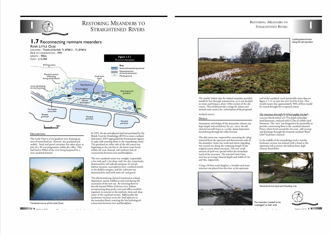
The Little Ouse is a low gradient river draining anarea of mixed land use (forestry, dry grassland andarable). Sand and gravel extraction has taken place aspart of a 30 year programme within the valley. Thishad lead to 900m of the river being bypassed by a new canalised channel.
In 1991, the site and adjacent land was purchased by theBritish Trust for Ornithology (BTO) to create a wetlandbird reserve. BTO approached the Environment Agency to assist with restoring flows to the meandering course.The grassland on either side of the old course wasbeginning to dry out due to the lower water levels
within the new channel, and resultant lack of connectivity between river and floodplain.
The new canalised course was straight, trapezoidal,c.6m wide and 1-2m deep, with 3m dry, steep banksdominated by tall ruderals and grass. In-streamhabitat was poor, macrophytes were confined mainly to the shallow margins, and the substrate wasdominated by sand with some silt and gravel.
The old meandering channel remained as a dampdepression, merely infilled at each end during theexcavation of the new cut. By restoring flows tothe old channel 900m of diverse river habitatincorporating deep pools, runs and riffles would beregained, in contrast to the uniform, slack and deep
water of the canalised section. Additionally, thelandowner was keen to see the land adjacent tothe meanders flood, restoring the lost hydrologicalconnection between river and floodplain.
Riffle
Riffle
Riffle
Floodedgravel pit
Floodedgravel pit
Floodedgravel pit
Pool
Pool
Main flood area
BTO boundary
Maximum extentof flooding
during winter floods
Permeablestone dam
L i t t l e O u s e Straightened
channel(backwater)
Restored meandering channel
Retained sectionof marshy backwater
Marshy ground
Breached bank Semi-improved
grassland
Juncus developingon marshy ground
Small earthbund
Pond
Key
0 100m
Figure 1.7.1
PLAN OF MEANDERS
Canalised course of the Little Ouse
1
R ESTORING MEANDERS TO
STRAIGHTENED R IVERS
The marshy habitat that the isolated meanders provided would be lost through reconnection, so it was decidedto retain and bypass a short 120m section of the oldcourse. This would provide a refuge for plants andanimals and a source for colonisation of the proposed
wetland reserve.
DESIGN
Assessment and design of the restoration scheme waskept simple and carried out ‘by eye’, since the oldchannel was still intact as a reedy, damp depressionmeandering through the valley bottom.
The old course was reopened by excavating the ‘plug’material from the upstream and downstream ends of the meanders. Some tree work and minor regrading
was carried out along the remaining length of theoriginal course where necessary. The very smallamount of spoil was spread within the immediatereach of the excavator. The restored Little Ousenow has an average channel depth and width of 1mand 8m, respectively.
Using a 50 foot reach dragline, a boulder and stonestructure was placed into the river at the upstream
end of the canalised reach (permeable stone dam onfigure 1.7.1), to raise the river level by 0.6m. This
would ensure that approximately 90% of flow wouldbe routed through the re-opened course.
The structure, 6m wide by 10m long by 2m high, was constructed using 1.5 by 1m prefabricatedconcrete blocks below a 0.75m depth of bouldersized limestone, surfaced with 0.25m of cobble sizedlimestone. The ‘weir’ was designed to be permeable toprovide a sweetening flow to the canalised channel.Flows, where levels exceed the 2m crest, will overtopand discharge through the retained canalised ‘floodrelief’ backwater channel.
In the middle of the meandering reach a marshy backwater section was isolated with a bund at theupstream end to protect the habitat from highvelocity flood flows.
Looking downstreamalong the old meanders
The meanders needed to be‘unplugged’ at both ends
Sluice,bund and upstream flooding area
7/27/2019 MAN_mod
http://slidepdf.com/reader/full/manmod 17/84
R ESTORING MEANDERS TO
STRAIGHTENED R IVERS1
SUBSEQUENT PERFORMANCE 1994 – 2000
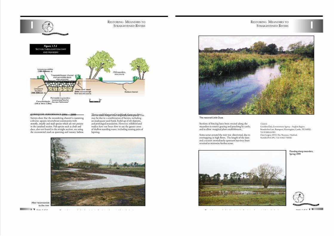
Surveys show that the meandering channel is sustaining a diverse aquatic invertebrate community, withstonefly, mayfly and snail species which are not presentin the canalised section. Fish species such as chub anddace, also not found in the straight section, are using the reconnected reach as spawning and nursery habitat.
The re-establishment of marshland plants on thissite has taken longer than originally anticipated. Thismay be due to a combination of factors, including an inadequate seed-bank, build-up of silt deposits,and prolonged inundation. However, wildfowl and
waders have not been slow to use the greater areasof shallow standing water, including nesting pairs of lapwing.
0 2m
Water level raised0.6m to encourageflow into old course
Shallow channel
Old meanders,new course
Concrete blocks(1m x 1m x 1.5m)
Limestoneboulders
(300–500mm ø)
Limestone cobbles(100–200mm ø)
Permeable to provide a'sweetening' flow forthe new 'backwater'
Trapezoidal bypass channelwith permeable block
weir structure
Figure 1.7.2
SECTION THROUGHSTONE DAM
AND MEANDERS
After reconnectionto the river
Sections of fencing have been erected along themeanders to restrict grazing and poaching by cattle,and to allow marginal plant establishment.
Some scour around the weir was discovered, due toovertopping in high flows. The length of the damand a section immediately upstream has since beenrevetted to minimise further scour.
Contacts:
Geraldine Daly, Environment Agency – Anglian Region,
Bromholme Lane, Brampton, Huntingdon, Cambs, PE18 8NE,
Tel: 01480 414581.
Chris Gregory. BTO, The Nunnery, Thetford,
Norfolk IP24 2PU, Tel: 01842 750050.
1
R ESTORING MEANDERS TO
STRAIGHTENED R IVERS
Flooding along meanders,Spring 1999
The restored Little Ouse
7/27/2019 MAN_mod
http://slidepdf.com/reader/full/manmod 18/84
ENHANCING R EDUNDANT
R IVER CHANNELS2
2.1 Creation of backwatersRIVER SKERNELOCATION - Darlington, Co.Durham NZ 301160
DATE OF CONSTRUCTION - Autumn 1995
COST - £3k
Flat margins createdand planted
Shoals and barsformed naturally
Old straightriver course
Deep water sustained
'Soft' revetments(see Part 4)
DESCRIPTION
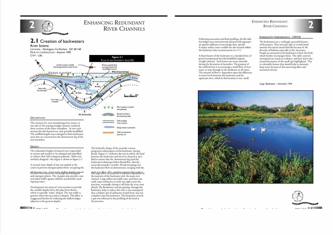
The creation of a new meandering river course, toone side of the existing straight channel, renderedshort sections of the latter redundant. At two suchsections the old channel was only partially backfilled.The unfilled lengths were enlarged to form backwaterareas that are connected to the downstream leg of thenew meanders.
DESIGN
The redundant lengths of channel were trapezoidalin section and needed to be enlarged and reprofiledto achieve their full ecological potential. Both weresimilarly designed - the largest is shown in figure 2.1.
A normal water depth of 2m was needed in thecentre to prevent emergent plants from occupying the
whole water area. Conversely, shallow depths aroundthe sides were needed to encourage both marginaland emergent plants. The margins also provide a nat-ural safety buffer against children accidentally reach-ing deep water.
Development of a series of cross-sections to providethe variable depths led to the plan form shown,
which is typically ‘onion’ shaped. The top width isgreatest where the excavation is deepest. The effect isexaggerated further by widening the shallow ledgesadjacent to the greatest depths.
The hydraulic design of the meander ensuresprogressive submergence of the backwater during floods. Figure 2.1 indicates the way in which the landbetween the backwater and the river channel is pro-filed to ensure that the downstream leg (and thebackwater) submerges before floods flow directly across the meander corridor. Floods sweeping overthe backwater flow on downstream, merging with the
main river flow. The complex currents that result atthis stage affect the patterns of sediment deposition atthe junction of the backwater with the main riverchannel. Large eddies inevitably arise, and these caneasily cause sediments to settle out right across the
junction, eventually closing it off from the river com-pletely. The floodwater currents passing through thebackwater help to reduce this risk; it was anticipatedthat a shallow spit of sediments would form, but notcomplete close the backwater. The formation of sucha spit was reflected in the profiling of the land atthe junction.
42.2m (exist)
N e w
m e a n d
e r
41.9m
41.5m
42.4m (existing)
2m Depth
Old bank r e - p ro f i l e d
Surface water outfalldischarges below water level
Porous gravel lensincorporated intobackfilled course
Naturallyformed spit
Low 'spit'created
Floods
R S k e r n e
0 20m10
N
Figure 2.1
PLAN OF BACKWATERAT BEND N2
2
ENHANCING R EDUNDANT
R IVER CHANNELS
Following excavation and final profiling, the flat shal-low ledges were intermittently planted with appropri-ate species sufficient to encourage their spread.
A major surface water outfall was also located withinthe backwater after reconstruction (see 9.1).
A final feature of the backwater is a simulated lens of gravel incorporated into the backfilled originalstraight channel. Such lenses can occur naturally during the formation of meanders. The purpose of the artificial lens is to encourage a small flow of river
water to seep through to the backwater at all times.The amount of flow is dependent upon the differencein water levels between the backwater and theupstream river, which in this location is very small.
SUBSEQUENT PERFORMANCE - 1995/8
The backwaters are a strikingly successful featureof the project. They not only add to overall visualamenity but attract much bird life because of thediversity of habitats especially at the junctions.People are attracted to the backwater to feed the birds
which further encourages them. The eddy currentsanticipated are much in evidence, and have led to thenatural formation of the small spit highlighted. Thisis a desirable feature that should help to maintaindeep water because of the narrowing effect andincreased velocity.
Large Backwater – November 1996
7/27/2019 MAN_mod
http://slidepdf.com/reader/full/manmod 19/84
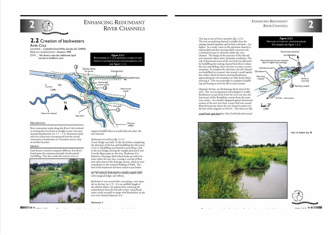
DESCRIPTION
River restoration works along the River Cole involvedre-routing the river from its straight course into new meandering channels (see 1.1 – 1.3). Remnants of theold river course were incorporated into the overallrestoration as backwaters at 3 locations and as a bay at another location.
DESIGN
Each feature created is uniquely different, but all arebased upon the common principle of only partialbackfilling. This also avoids the need to revet or
support backfill where it would otherwise abut thenew channel.
Backwaters on mill leat (fig. 2.2.1) A new bridge was built ‘in the dry’ before completing the diversion of the leat and backfilling the old course(see 8.2). Backfilling was limited to providing a link to the new bridge, leaving the lengths denoted 2 and3 on the figure open to the river. Backwater 2 islinked to a drainage ditch which backs up with river
water when the leat rises, creating a reversal of flow into other parts of the drainage system, which in turncontributes to the seasonal flooding of fields. Thebed of this backwater has been raised to just below
normal water level to sustain a marshy aquatic habi-tat. In contrast, backwater 3 remains as open water with marginal ledges and willows.
Backwater 1 was created after excavating a new mean-der in the leat (see 1.3). It is an unfilled length of the old leat which was enhanced by removing theembankment from the left side so that rising flood-
water could overspill to merge with floodwaters in thenew river channel adjacent to it.
ENHANCING R EDUNDANT
R IVER CHANNELS2
2.2 Creation of backwatersRIVER COLELOCATION – Coleshill,Oxon/Wilts border,SU 234935
DATE OF CONSTRUCTION – Autumn 1995
COST–
No direct costs but additional spoil – carted to landform area
Drainage ditch
Mill Leat
Leat
Overspill
New river channel
Old leat infilledfor access
New courseof leat
New bridgeon new course
3
2
1
New ford
Old Leatinfilled
N
0 20m
1:2000
Figure 2.2.1BACKWATERS AT 1,2 , 3 DELINIATE COURSE OF LEAT
PRIORTO NEWBRIDGEAND NEWMEANDERIN LEAT
(see Figure 1.1.1)
Backwater 1
New bay at start of lower meanders (fig. 2.2.2)The new meandering channel is smaller than theexisting channel upstream and its bed is elevated c. 1mhigher. As a result, water in the upstream channel isimpounded and slow moving which contrasts witha marked increase in velocities within the new channel. The design of the junction of the old andnew channels reflects these hydraulic conditions. Therisk of downward scour of the new bed was alleviatedby backfilling the existing channel bed where it abutsthe new and adding a layer of stone to create a securetransition. To complete the diversion, the old channel
was backfilled in a manner that created a small marshy bay within which the slower moving floodwatersapproaching the new meander can eddy freely beforeentering it. This was preferable to complete backfill-ing and having to revet the fill to resist erosion.
Opposite the bay, an old drainage ditch entered theriver. This was incorporated and enlarged to enablefloodwaters to pass freely from the river out onto thelowest part of the floodplain, remote from the mainriver course. As a further safeguard against downwarderosion of the new river bed, a stone ford was created80m downstream where the new channel crosses overthe line of the original (see Part 8). This ford acts like
a small weir and therefore ‘fixes’ both bed and normal water levels upstream.
2
ENHANCING R EDUNDANT
R IVER CHANNELS
Flood waters diverted
onto floodplain
Stone onriver bed
New bay created
R.Cole – new course
New fordcreated
Old willow
Hawthorn trees
River diverted into new meander(bed 1m higher than existing)
Backfilledcourse
X
0 20m
1:2000
Figure 2.2.2
NEW BAY ATSTARTOF LOWERMEANDERS
(For location see Figure 1.2.1)
View of shallow bay X
7/27/2019 MAN_mod
http://slidepdf.com/reader/full/manmod 20/84
ENHANCING R EDUNDANT
R IVER CHANNELS2
Small backwater A
New backwater
Newbackwater
Backfilledcourse
Partial backfill
310m 380m
Backfilledbank reveted
with coir matting
Bank revetedwith willow hurdles
Floods
A
B0 20m
Figure 2.2.3
BACKWATERS ON LOWER MEANDERSAT CH 310m AND 380m(see Figure 1.1.1)
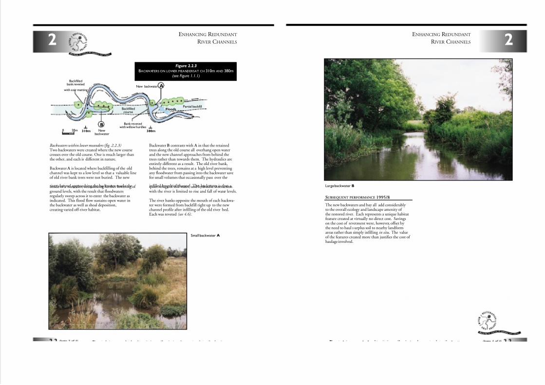
Backwaters within lower meanders (fig. 2.2.3)Two backwaters were created where the new coursecrosses over the old course. One is much larger thanthe other, and each is different in nature.
Backwater A is located where backfilling of the oldchannel was kept to a low level so that a valuable lineof old river bank trees were not buried. The new
river channel approaching the backwater marks theinside of a meander, necessitating further lowering of ground levels, with the result that floodwatersregularly sweep across it to enter the backwater asindicated. This flood flow sustains open water inthe backwater as well as shoal deposition,creating varied off-river habitat.
BackwaterB contrasts with A in that the retainedtrees along the old course all overhang open waterand the new channel approaches from behind thetrees rather than towards them. The hydraulics areentirely different as a result. The old river bank,behind the trees, remains at a high level preventing any floodwater from passing into the backwater savefor small volumes that occasionally pass over the
infilled length of channel. The backwater is thus a quiet refuge of still water, and hydraulic interaction with the river is limited to rise and fall of water levels.
The river banks opposite the mouth of each backwa-ter were formed from backfill right up to the new channel profile after infilling of the old river bed.Each was reveted (see 4.6).
2
ENHANCING R EDUNDANT
R IVER CHANNELS
Large backwater B
SUBSEQUENT PERFORMANCE 1995/8
The new backwaters and bay all add considerably to the overall ecology and landscape amenity of the restored river. Each represents a unique habitatfeature created at virtually no direct cost. Savingson the cost of revetment were, however, offset by the need to haul s urplus soil to nearby landformareas rather than simply infilling in situ. The valueof the features created more than justifies the cost of haulage involved.
7/27/2019 MAN_mod
http://slidepdf.com/reader/full/manmod 21/84
ENHANCING STRAIGHTENED
R IVER CHANNELS3
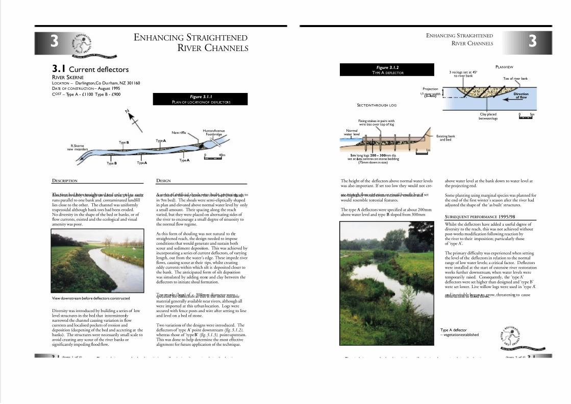
3.1 Current deflectorsRIVER SKERNELOCATION – Darlington,Co Du rham, NZ 301160
DATE OF CONSTRUCTION – August 1995
COST – Type A - £1100 Type B - £900
DESCRIPTION
The river had been straightened and enlarged to carry floodwaters safely through an urban area. A gas mainruns parallel to one bank and contaminated landfilllies close to the other. The channel was uniformly trapezoidal although bank toes had been eroded.No diversity in the shape of the bed or banks, or of flow currents, existed and the ecological and visualamenity was poor.
Diversity was introduced by building a series of low level structures in the bed that intermittently narrowed the channel causing variation in flow currents and localised pockets of erosion anddeposition (deepening of the bed and accreting at thebanks). The structures were necessarily small scale toavoid creating any scour of the river banks orsignificantly impeding flood flow.
DESIGN
A series of artificial shoals were built, projecting up toone third of the way across the river bed (3m shoalsin 9m bed). The shoals were semi-eliptically shapedin plan and elevated above normal water level by only a small amount. Their spacing along the reachvaried, but they were placed on alternating sides of the river to encourage a small degree of sinuosity tothe normal flow regime.
As this form of shoaling was not natural to thestraightened reach, the design needed to imposeconditions that would generate and sustain bothscour and sediment deposition. This was achieved by incorporating a series of current deflectors, of varying length, out from the water’s edge. These impede riverflows, causing scour at their tips, whilst creating eddy currents within which silt is deposited closer tothe bank. The anticipated form of silt deposition
was simulated by adding stone and clay between thedeflectors to initiate shoal formation.
Tree trunks (logs) of c. 300mm diameter werespecified for deflectors as this is the most suitablematerial generally available near rivers, although all
were imported at this urban location. Logs weresecured with fence posts and wire after setting to lineand level on a bed of stone.
Two variations of the designs were introduced. Thedeflectors of ‘type A ’ point downstream (fig. 3.1.2),
whereas those of ‘typeB’ (fig. 3.1.3), point upstream.This was done to help determine the most effectivealignment for future application of the technique.
Figure 3.1.1
PLAN OF LOCATIONOF DEFLECTORS
N
Type BTypeA
Hutton AvenueFootbridgeNew riffle
TypeATypeAType B
R.Skernenew meanders
40m0
View downstream before deflectors constructed
The height of the deflectors above normal water levels was also important. If set too low they would not cre-
ate enough flow variation or visual benefit but if settoo high they would create excessive erosion and would resemble terrestial features.
The type A deflectors were specified at about 200mmabove water level and type B sloped from 300mm
above water level at the bank down to water level atthe projecting end.
Some planting using marginal species was planned forthe end of the first winter’s season after the river hadadjusted the shape of the ‘as built’ structures.
SUBSEQUENT PERFORMANCE 1995/98
Whilst the deflectors have added a useful degree of diversity to the reach, this was not achieved withoutpost-works modification following reaction by the river to their imposition; particularly thoseof ‘type A’.
The primary difficulty was experienced when setting the level of the deflectors in relation to the normalrange of low water levels; a critical factor. Deflectors
were installed at the start of extensive river restoration works further downstream, when water levels weretemporari ly raised. Consequently, the ‘type A’deflectors were set higher than designed and ‘type B’
were set lower. Live willow logs were used in ‘type A’
and inevitably began to grow, threatening to causeobstruction to flood flows.
3
ENHANCING STRAIGHTENED
R IVER CHANNELS
Toe of river bank
Clay placedbetween logs
Directionof flow
3 no.logs set at 45°to river bank
Projection
1/3 river width(3–4m)
0 5m
Fixing stakes in pairs withwire ties over top of log
Existing bank and bed
Normalwater level
5m long logs 200 – 300mm diaset at 6m centres on stone bedding
(75mm down in size)
1m0
Figure 3.1.2
TYPE A DEFLECTOR
SECTIONTHROUGH LOG
PLANVIEW
Type A deflector – vegetation established
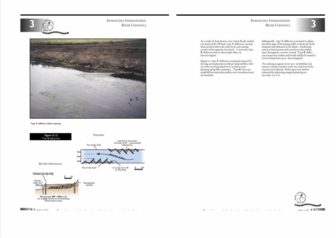
7/27/2019 MAN_mod
http://slidepdf.com/reader/full/manmod 22/84
D i r e c t i o n o f f l o w
Toe of river bank
Toe of river bank 5 no. logs set at 45°to river bank
Logs tied to each otherwith wire at 45° – stone backfill
behind wires
3m
3m
3m
0 5m
Fixing posts in pairs withwire ties over top of log
Existing bank and bed
Normalwater level
5m long logs 200 – 300mm diaset at 4.5m centres on stone bedding
(75mm down in size)
1m0
Figure 3.1.3
TYPE B DEFLECTOR
SECTION THROUGHLOG
PLANVIEW
ENHANCING STRAIGHTENED
R IVER CHANNELS3
Type B deflector before planting
3ENHANCING STRAIGHTENED
R IVER CHANNELS
As a result of these factors, over winter floods washedout much of the fill from ‘type A ’ deflectors, leaving them perched above the water level, and causing erosion of the opposite river bank. Conversely, ‘typeB’ deflectors had no discernible effect onthe river regime.
Repairs to ‘type A ’ deflectors comprised removal of the logs and replacement with pre-planted fibre rollsset at the surviving shoal level, as well as someplanting using fibre mattresses. ‘Type B’ were notmodified but some plant pallets were introduced nearthe bankside.
Subsequently ‘type A ’ deflectors continued to adjustbut show signs of becoming stable at about the levelsdesigned and indicated in the figure. Small poolsexist just downstream and currents are discernibly faster through the narrows created. ‘Type B’ deflec-tors remain less evident and would ideally be raised inlevel to bring them up to those designed.
The technique appears to be very worthwhile, butsuccess is clearly sensitive to the size and level of thestructures introduced. Both types were furtherenhanced by adjoining marginal planting at a later date (see 3.2).
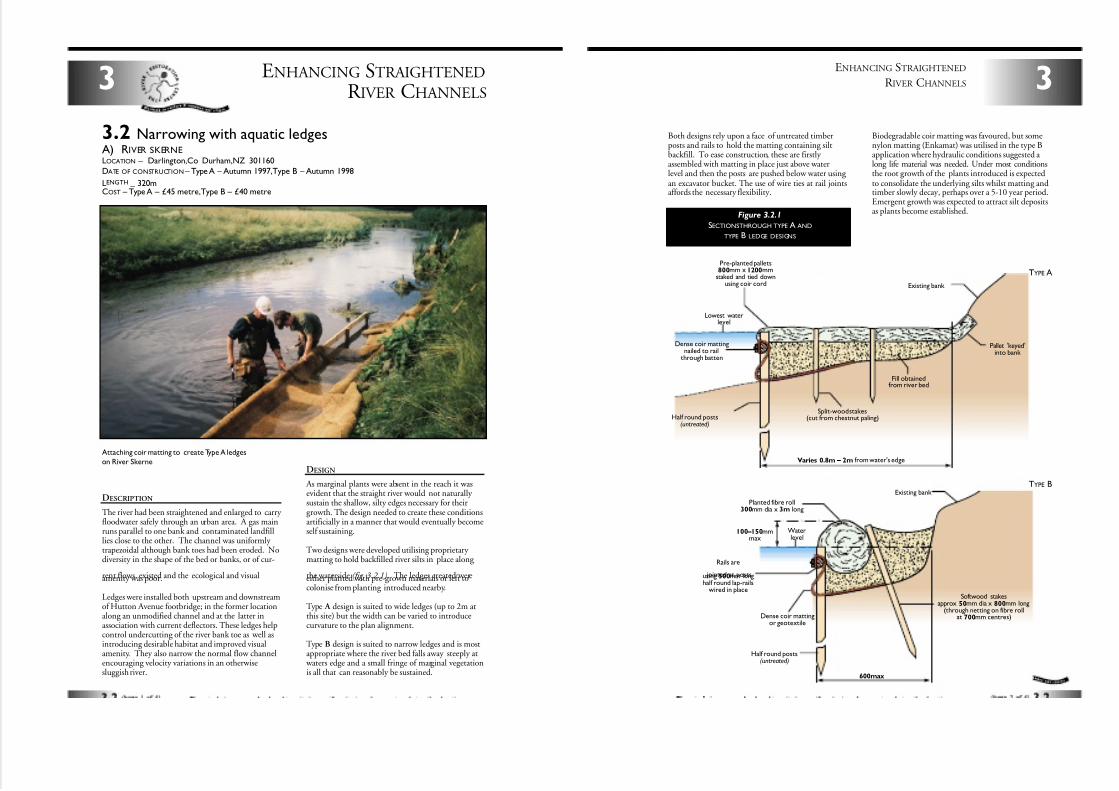
7/27/2019 MAN_mod
http://slidepdf.com/reader/full/manmod 23/84
ENHANCING STRAIGHTENED
R IVER CHANNELS3
3.2 Narrowing with aquatic ledgesA) RIVER SKERNELOCATION – Darlington,Co Durham,NZ 301160
DATE OF CONSTRUCTION – Type A – Autumn 1997,Type B – Autumn 1998
LENGTH–
320mCOST – Type A – £45 metre,Type B – £40 metre
DESCRIPTION
The river had been straightened and enlarged to carry floodwater safely through an urban area. A gas mainruns parallel to one bank and contaminated landfilllies close to the other. The channel was uniformly trapezoidal although bank toes had been eroded. Nodiversity in the shape of the bed or banks, or of cur-
rent flows, existed and the ecological and visualamenity was poor.
Ledges were installed both upstream and downstreamof Hutton Avenue footbridge; in the former locationalong an unmodified channel and at the latter inassociation with current deflectors. These ledges helpcontrol undercutting of the river bank toe as well asintroducing desirable habitat and improved visualamenity. They also narrow the normal flow channelencouraging velocity variations in an otherwisesluggish river.
Attaching coir matting to create Type A ledges
on River SkerneDESIGN
As marginal plants were absent in the reach it wasevident that the straight river would not naturally sustain the shallow, silty edges necessary for theirgrowth. The design needed to create these conditionsartificially in a manner that would eventually becomeself sustaining.
Two designs were developed utilising proprietary matting to hold backfilled river silts in place along
the waterside (fig. 3.2.1). The ledges created wereeither planted with pre-grown materials or left tocolonise from planting introduced nearby.
Type A design is suited to wide ledges (up to 2m atthis site) but the width can be varied to introducecurvature to the plan alignment.
Type B design is suited to narrow ledges and is mostappropriate where the river bed falls away steeply at
waters edge and a small fringe of marginal vegetationis all that can reasonably be sustained.
3
ENHANCING STRAIGHTENED
R IVER CHANNELS
Both designs rely upon a face of untreated timberposts and rails to hold the matting containing siltbackfill. To ease construction, these are firstly assembled with matting in place just above waterlevel and then the posts are pushed below water using an excavator bucket. The use of wire ties at rail jointsaffords the necessary flexibility.
Biodegradable coir matting was favoured, but somenylon matting (Enkamat) was utilised in the type Bapplication where hydraulic conditions suggested a long life material was needed. Under most conditionsthe root growth of the plants introduced is expectedto consolidate the underlying silts whilst matting andtimber slowly decay, perhaps over a 5-10 year period.Emergent growth was expected to attract silt depositsas plants become established.
Figure 3.2.1
SECTIONSTHROUGH TYPE A AND
TYPE B LEDGE DESIGNS
Varies 0.8m – 2m from water's edge
Lowest waterlevel
Dense coir mattingnailed to rail
through batten
Half round posts(untreated)
Split-wood stakes(cut from chestnut paling)
Fill obtainedfrom river bed
Existing bank
Pallet 'keyed'into bank
Pre-planted pallets800mm x 1200mm
staked and tied downusing coir cord
600max
100 – 150mmmax
Waterlevel
Dense coir mattingor geotextile
Half round posts(untreated)
Softwood stakesapprox 50mm dia x 800mm long
(through netting on fibre rollat 700mm centres)
Existing bank
Planted fibre roll300mm dia x 3m long
Rails are
jointed at postsusing 500mm longhalf round lap-rails
wired in place
TYPE A
TYPE B
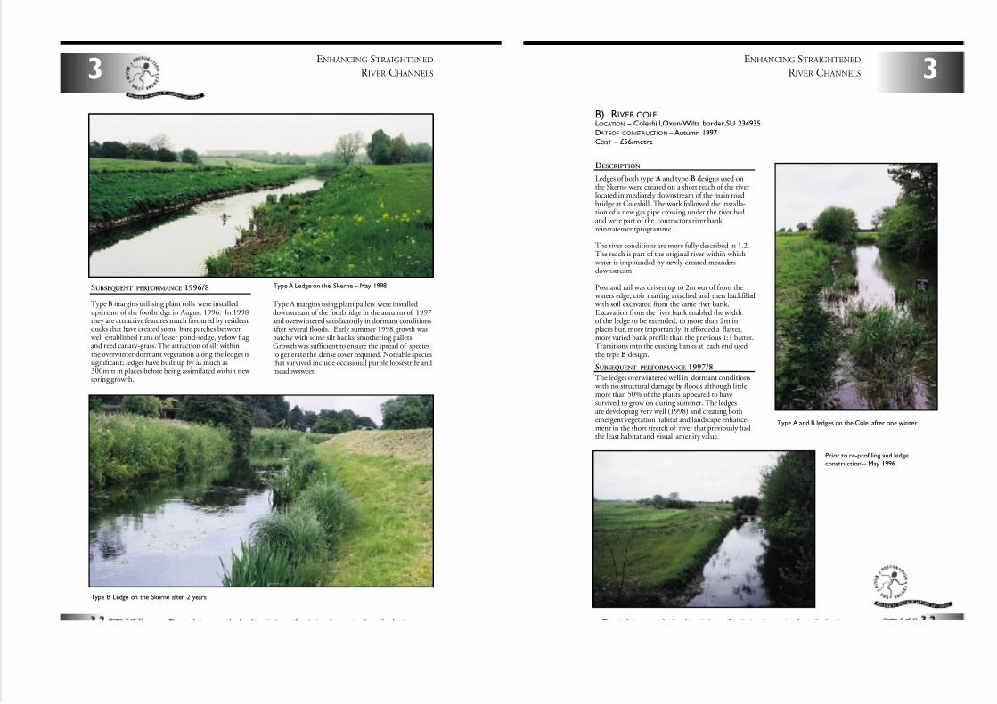
7/27/2019 MAN_mod
http://slidepdf.com/reader/full/manmod 24/84
SUBSEQUENT PERFORMANCE 1996/8
Type B margins utilising plant rolls were installedupstream of the footbridge in August 1996. In 1998they are attractive features much favoured by residentducks that have created some bare patches between
well established runs of lesser pond-sedge, yellow flag and reed canary-grass. The attraction of silt withinthe overwinter dormant vegetation along the ledges issignificant; ledges have built up by as much as300mm in places before being assimilated within new spring growth.
Type A margins using plant pallets were installeddownstream of the footbridge in the autumn of 1997and overwintered satisfactorily in dormant conditionsafter several floods. Early summer 1998 growth waspatchy with some silt banks smothering pallets.Growth was sufficient to ensure the spread of speciesto generate the dense cover required. Noteable speciesthat survived include occasional purple loosestrife andmeadowsweet.
3
Type A Ledge on the Skerne – May 1998
ENHANCING STRAIGHTENED
R IVER CHANNELS
Type B Ledge on the Skerne after 2 years
DESCRIPTION
Ledges of both type A and type B designs used onthe Skerne were created on a short reach of the riverlocated immediately downstream of the main roadbridge at Coleshill. The work followed the installa-tion of a new gas pipe crossing under the river bedand were part of the contractors river bank reinstatement programme.
The river conditions are more fully described in 1.2.The reach is part of the original river within which
water is impounded by newly created meandersdownstream.
Post and rail was driven up to 2m out of from the waters edge, coir matting attached and then backfilled with soil excavated from the same river bank.Excavation from the river bank enabled the widthof the ledge to be extended, to more than 2m inplaces but, more importantly, it afforded a flatter,more varied bank profile than the previous 1:1 batter.Transitions into the existing banks at each end usedthe type B design.
SUBSEQUENT PERFORMANCE 1997/8
The ledges overwintered well in dormant conditions with no structural damage by floods although littlemore than 50% of the plants appeared to havesurvived to grow on during summer. The ledgesare developing very well (1998) and creating bothemergent vegetation habitat and landscape enhance-ment in the short stretch of river that previously hadthe least habitat and visual amenity value.
3
ENHANCING STRAIGHTENED
R IVER CHANNELS
B) RIVER COLELOCATION – Coleshill,Oxon/Wilts border,SU 234935
DATEOF CONSTRUCTION – Autumn 1997COST – £56/metre
Type A and B ledges on the Cole after one winter
Prior to re-profiling and ledgeconstruction – May 1996
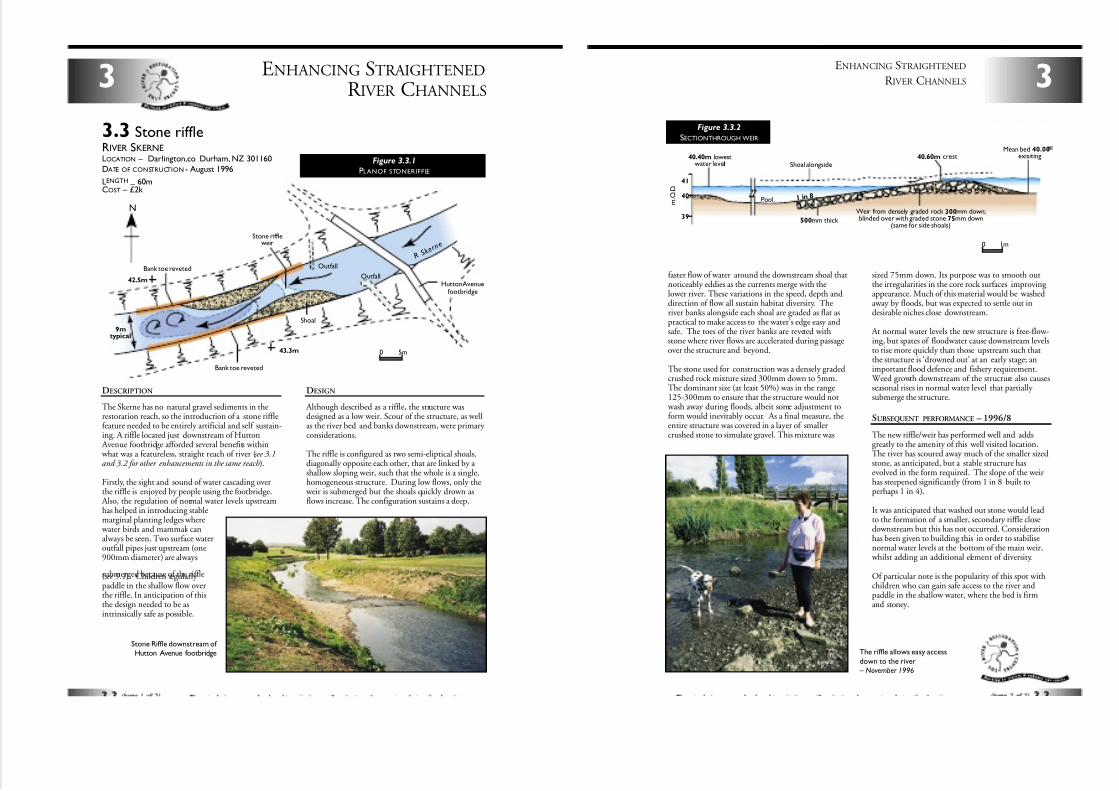
7/27/2019 MAN_mod
http://slidepdf.com/reader/full/manmod 25/84
ENHANCING STRAIGHTENED
R IVER CHANNELS3
3.3 Stone riffleRIVER SKERNELOCATION – Darlington,co Durham, NZ 301160
DATE OF CONSTRUCTION - August 1996
LENGTH–
60mCOST – £2k
DESCRIPTION
The Skerne has no natural gravel sediments in therestoration reach, so the introduction of a stone rifflefeature needed to be entirely artificial and self sustain-ing. A riffle located just downstream of Hutton
Avenue footbridge afforded several benefits within what was a featureless, straight reach of river (see 3.1and 3.2 for other enhancements in the same reach).
Firstly, the sight and sound of water cascading overthe riffle is enjoyed by people using the footbridge.
Also, the regulation of normal water levels upstreamhas helped in introducing stablemarginal planting ledges where
water birds and mammals canalways be seen. Two surface wateroutfall pipes just upstream (one900mm diameter) are always
submerged because of the riffle(see 9.1). Children regularly paddle in the shallow flow overthe riffle. In anticipation of thisthe design needed to be asintrinsically safe as possible.
DESIGN
Although described as a riffle, the structure wasdesigned as a low weir. Scour of the structure, as wellas the river bed and banks downstream, were primary considerations.
The riffle is configured as two semi-eliptical shoals,diagonally opposite each other, that are linked by a shallow sloping weir, such that the whole is a single,homogeneous structure. During low flows, only the
weir is submerged but the shoals quickly drown asflows increase. The configuration sustains a deep,
Stone Riffle downstream of Hutton Avenue footbridge
43.3m
42.5mOutfall
Shoal
Bank toe reveted
Bank toe reveted
Stone riffleweir
Outfall
Hutton Avenuefootbridge
R S k e r
n e
0 5m
9mtypical
N
Figure 3.3.1
PLANOF STONERIFFLE
3
ENHANCING STRAIGHTENED
R IVER CHANNELS
faster flow of water around the downstream shoal thatnoticeably eddies as the currents merge with thelower river. These variations in the speed, depth anddirection of flow all sustain habitat diversity. Theriver banks alongside each shoal are graded as flat aspractical to make access to the water’s edge easy andsafe. The toes of the river banks are reveted withstone where river flows are accelerated during passageover the structure and beyond.
The stone used for construction was a densely gradedcrushed rock mixture sized 300mm down to 5mm.The dominant size (at least 50%) was in the range125-300mm to ensure that the structure would not
wash away during floods, albeit some adjustment toform would inevitably occur. As a final measure, theentire structure was covered in a layer of smallercrushed stone to simulate gravel. This mixture was
sized 75mm down. Its purpose was to smooth outthe irregularities in the core rock surfaces improving appearance. Much of this material would be washedaway by floods, but was expected to settle out indesirable niches close downstream.
At normal water levels the new structure is free-flow-ing, but spates of floodwater cause downstream levelsto rise more quickly than those upstream such thatthe structure is ‘drowned out’ at an early stage; animportant flood defence and fishery requirement.
Weed growth downstream of the structure also causesseasonal rises in normal water level that partially submerge the structure.
SUBSEQUENT PERFORMANCE – 1996/8
The new riffle/weir has performed well and addsgreatly to the amenity of this well visited location.The river has scoured away much of the smaller sizedstone, as anticipated, but a stable structure hasevolved in the form required. The slope of the weirhas steepened significantly (from 1 in 8 built toperhaps 1 in 4).
It was anticipated that washed out stone would leadto the formation of a smaller, secondary riffle closedownstream but this has not occurred. Considerationhas been given to building this in order to stabilisenormal water levels at the bottom of the main weir,
whilst adding an additional element of diversity.
Of particular note is the popularity of this spot withchildren who can gain safe access to the river andpaddle in the shallow water, where the bed is firmand stoney.
41
40
39
40.60m crestMean bed 40.00
exisiting
Weir from densely graded rock 300mm down;blinded over with graded stone 75mm down
(same for side shoals)
40.40m lowestwater level Shoal alongside
500mm thick
Pool 1 in 8
0 1m
m . O . D .
The riffle allows easy access
down to the river – November 1996
Figure 3.3.2
SECTIONTHROUGH WEIR
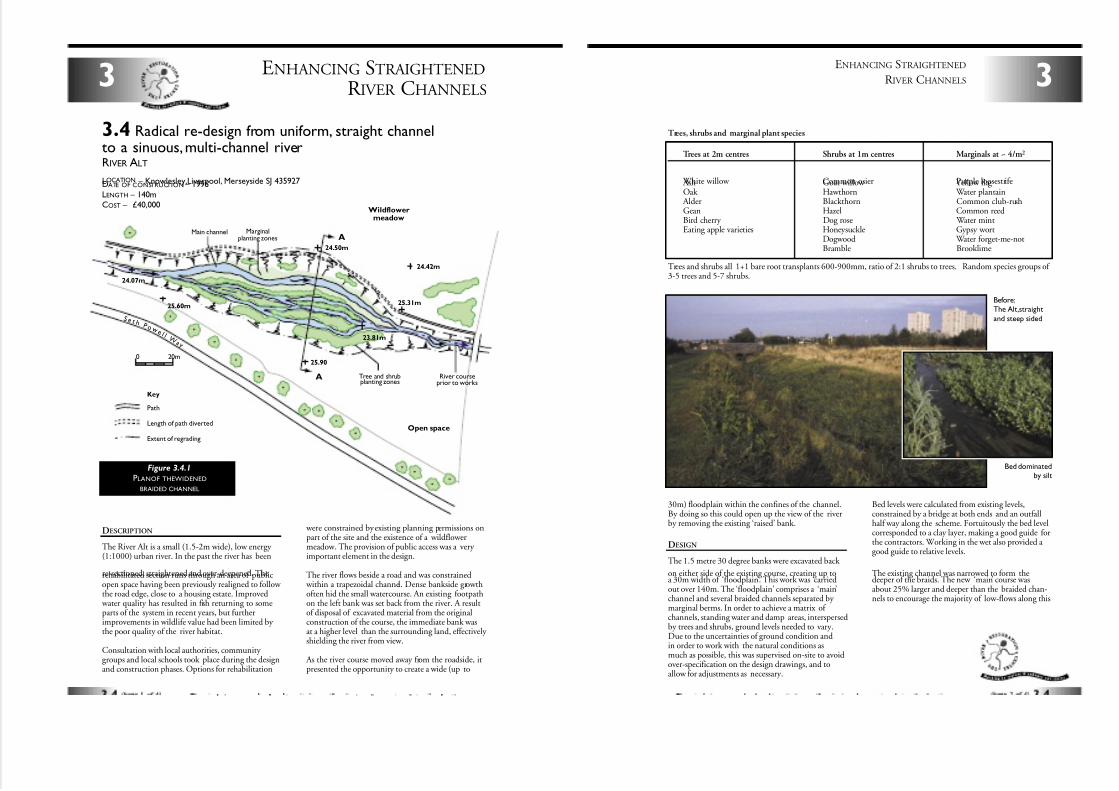
7/27/2019 MAN_mod
http://slidepdf.com/reader/full/manmod 26/84
DESCRIPTION
The River Alt is a small (1.5-2m wide), low energy (1:1000) urban river. In the past the river has been
re-sectioned, straightened and over-deepened. Therehabilitated section runs through an area of publicopen space having been previously realigned to follow the road edge, close to a housing estate. Improved
water quality has resulted in fish returning to someparts of the system in recent years, but furtherimprovements in wildlife value had been limited by the poor quality of the river habitat.
Consultation with local authorities, community groups and local schools took place during the designand construction phases. Options for rehabilitation
were constrained by existing planning permissions onpart of the site and the existence of a wildflowermeadow. The provision of public access was a very important element in the design.
The river flows beside a road and was constrained within a trapezoidal channel. Dense bankside growthoften hid the small watercourse. An existing footpathon the left bank was set back from the river. A resultof disposal of excavated material from the originalconstruction of the course, the immediate bank wasat a higher level than the surrounding land, effectively shielding the river from view.
As the river course moved away from the roadside, itpresented the opportunity to create a wide (up to
ENHANCING STRAIGHTENED
R IVER CHANNELS3
3.4 Radical re-design from uniform, straight channelto a sinuous,multi-channel riverRIVER ALT
LOCATION – Knowlesley,Liverpool, Merseyside SJ 435927DATE OF CONSTRUCTION – 1996
LENGTH – 140mCOST – £40,000
0 20m
Main channel
Open space
Wildflower meadow
Marginalplanting zones
Tree and shrubplanting zones
River courseprior to works
S e t h P o w
e l l W
a y
Key
Path
Length of path diverted
Extent of regrading
A
A
25.31m
25.90
24.50m
25.60m
24.07m
23.81m
24.42m
Figure 3.4.1
PLANOF THEWIDENED
BRAIDED CHANNEL
30m) floodplain within the confines of the channel.By doing so this could open up the view of the riverby removing the existing ‘raised’ bank.
DESIGN
The 1.5 metre 30 degree banks were excavated back
on either side of the existing course, creating up toa 30m width of ‘floodplain’. This work was carriedout over 140m. The ‘floodplain’ comprises a ‘main’channel and several braided channels separated by marginal berms. In order to achieve a matrix of channels, standing water and damp areas, interspersedby trees and shrubs, ground levels needed to vary.Due to the uncertainties of ground condition andin order to work with the natural conditions asmuch as possible, this was supervised on-site to avoidover-specification on the design drawings, and toallow for adjustments as necessary.
Bed levels were calculated from existing levels,constrained by a bridge at both ends and an outfallhalf way along the scheme. Fortuitously the bed levelcorresponded to a clay layer, making a good guide forthe contractors. Working in the wet also provided a good guide to relative levels.
The existing channel was narrowed to form thedeeper of the braids. The new ‘main’ course wasabout 25% larger and deeper than the braided chan-nels to encourage the majority of low-flows along this
3
ENHANCING STRAIGHTENED
R IVER CHANNELS
Trees at 2m centres Shrubs at 1m centres Marginals at ~ 4/m2
White willow Common osier Purple loosestrife Ash Goat willow Yellow flag Oak Hawthorn Water plantain
Alder Blackthorn Common club-rushGean Hazel Common reedBird cherry Dog rose Water mintEating apple varieties Honeysuckle Gypsy wort
Dogwood Water forget-me-notBramble Brooklime
Trees, shrubs and marginal plant species
Trees and shrubs all 1+1 bare root transplants 600-900mm, ratio of 2:1 shrubs to trees. Random species groups of 3-5 trees and 5-7 shrubs.
Before:The Alt,straight
and steep sided
Bed dominatedby silt
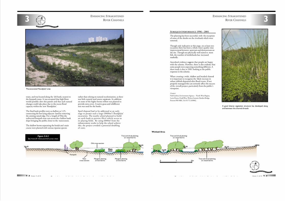
7/27/2019 MAN_mod
http://slidepdf.com/reader/full/manmod 27/84
ENHANCING STRAIGHTENED
R IVER CHANNELS3
route, and was located along the left bank, nearest tothe footpath route. It was accepted that high flows
would possibly alter this pattern and that such naturalchanges could take place due to the excess floodcapacity within the new ‘floodplain’.
The final bank profiles were as shallow as 1:25,connecting the low lying adjacent land by removing the existing raised edge. For a length of 50m theredirected footpath now cuts across the s hallow bank slope bringing the public closer to the watercourse.
The shallow berms separating the braids and maincourse were planted with various riparian species
rather than relying on natural recolonisation, as there was little natural seed source upstream. In additionon some of the higher berms willow was planted toprovide extra cover. A native grass and wildflowermix was used for the banks.
Spoil disposal had to be addressed at an early stage to permit such a large (9000m3) ‘floodplain’excavation. The nearby school planned to buildan earth bank to prevent illicit vehicle access toits playing fields. By using 6000m3 from theenhancement works to help the school achievethis, the project avoided a potential doubling of costs.
25.5524.43
Marginal plantingon low berms
Marginal plantingon low berms
Newcross-section
Mainriver
Tree and shrub plantingon raised berms
Old cross-section
Footpath
Figure 3.4.2
SECTION A THROUGHWETLAND AREA
The excavated ‘floodplain’ area
SUBSEQUENTPERFORMANCE 1996 – 2001
The planting has been successful, with the exceptionof some of the shrubs on the riverbank which wereremoved.
Though only indicative at this stage, on at least twooccasions there has been a whole water quality classimprovement between upstream and downstream onthe site. Though not physically well suited to mostfish, the number of sticklebacks has increasedmarkedly.
Anecdotal evidence suggests that people are happy with the scheme. However, there is also evidence thatsome people were expecting something different. A short study is due in 2001 looking at the publicresponse to the scheme.
When creating a wide, shallow and braided channelit is important to recognise the likely increase inurban rubbish deposited after flood events. If notproperly managed this can seriously affect the successof the overall project, particularly from the public’sviewpoint.
Contact:
Neil Guthrie, Environment Agency – North-West Region,
Lutra House, Dodd Way, Walton Summit, Bamber Bridge,
Preston PR5 8BX, Tel: 01772 339882.
3
ENHANCING STRAIGHTENED
R IVER CHANNELS
25.3224.99
24.00
25.90
Tree and shrub plantingon raised berms
Tree and shrub plantingon raised berms
Wetland Area
0 10m5
A good diverse vegetation structure has developed along
and between the channel threads
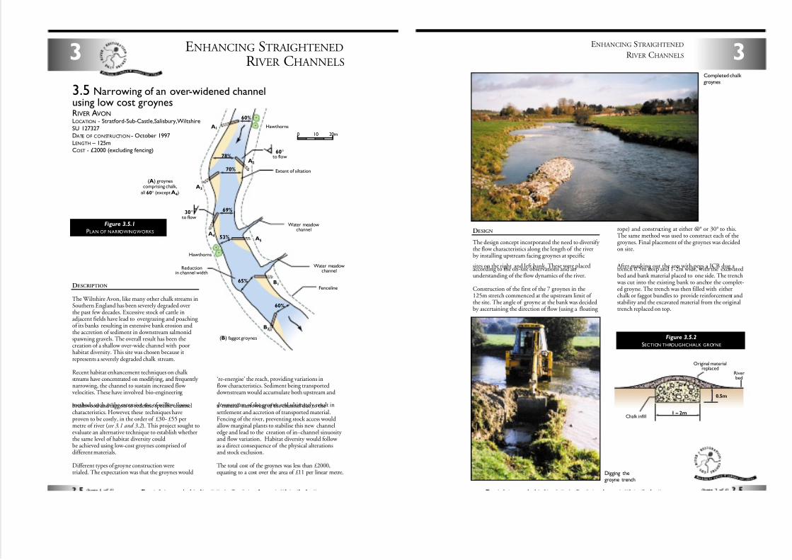
7/27/2019 MAN_mod
http://slidepdf.com/reader/full/manmod 28/84
0 20m10
60%
65%
53%
69%
70%
78%
60%
Water meadowchannel
Reductionin channel width
Water meadowchannel
Fenceline
Extent of siltation
Hawthorns
(A) groynescomprising chalk,
all 60° (except A4)
(B) faggot groynes
Hawthorns
B1
A5
A2
A3
30°to flow
60°to flow
A1
A4
B2
ENHANCING STRAIGHTENED
R IVER CHANNELS3
DESCRIPTION
The Wiltshire Avon, like many other chalk streams inSouthern England has been severely degraded overthe past few decades. Excessive stock of cattle inadjacent fields have lead to overgrazing and poaching of its banks resulting in extensive bank erosion andthe accretion of sediment in downstream salmonidspawning gravels. The overall result has been thecreation of a shallow over-wide channel with poorhabitat diversity. This site was chosen because itrepresents a severely degraded chalk stream.
Recent habitat enhancement techniques on chalk streams have concentrated on modifying, and frequently narrowing, the channel to sustain increased flow velocities. These have involved bio-engineering
methods such as the extensive use of willow, loosebrushwood and faggots to redefine specific channelcharacteristics. However, these techniques haveproven to be costly, in the order of £30- £55 permetre of river (see 3.1 and 3.2 ). This project sought toevaluate an alternative technique to establish whetherthe same level of habitat diversity couldbe achieved using low-cost groynes comprised of different materials.
Different types of groyne construction weretrialed. The expectation was that the groynes would
‘re-energise’ the reach, providing variations inflow characteristics. Sediment being transporteddownstream would accumulate both upstream and
downstream of the groyne and ultimately result ina ‘natural’ narrowing of the channel due to thesettlement and accretion of transported material.Fencing of the river, preventing stock access wouldallow marginal plants to stabilise this new channeledge and lead to the creation of in–channel sinuosity and flow variation. Habitat diversity would follow as a direct consequence of the physical alterationsand stock exclusion.
The total cost of the groynes was less than £2000,equating to a cost over the area of £11 per linear metre.
3.5 Narrowing of an over-widened channelusing low cost groynesRIVER AVONLOCATION - Stratford-Sub-Castle,Salisbury,Wiltshire
SU 127327DATE OF CONSTRUCTION - October 1997
LENGTH – 125mCOST - £2000 (excluding fencing)
Figure 3.5.1
PLAN OF NARROWINGWORKS DESIGN
The design concept incorporated the need to diversify the flow characteristics along the length of the riverby installing upstream facing groynes at specific
sites on the right and left bank. These were placedaccording to the on-site observations and anunderstanding of the flow dynamics of the river.
Construction of the first of the 7 groynes in the125m stretch commenced at the upstream limit of the site. The angle of groyne at the bank was decidedby ascertaining the direction of flow (using a floating
rope) and constructing at either 60° or 30° to this.The same method was used to construct each of thegroynes. Final placement of the groynes was decidedon site.
After marking out the area with pegs a JCB dug a trench 0.5m deep and 1-2m wide, with the excavatedbed and bank material placed to one side. The trench
was cut into the existing bank to anchor the complet-ed groyne. The trench was then filled with eitherchalk or faggot bundles to provide reinforcement andstability and the excavated material from the originaltrench replaced on top.
3
ENHANCING STRAIGHTENED
R IVER CHANNELS
0.5m
1 – 2mChalk infill
Original materialreplaced
Riverbed
Figure 3.5.2
SECTION THROUGHCHALK GROYNE
Digging thegroyne trench
Completed chalk groynes
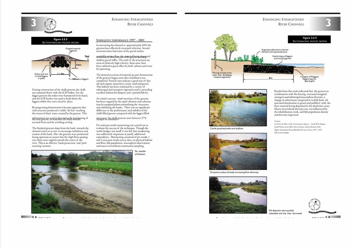
7/27/2019 MAN_mod
http://slidepdf.com/reader/full/manmod 29/84
ENHANCING STRAIGHTENED
R IVER CHANNELS3
During construction of the chalk groynes the chalk was rammed down with the JCB bucket. For thefaggot groynes the stakes were hammered in by hand,and the JCB bucket was used to hold down thefaggots whilst they were wired in place.
By progressing downstream it became apparent thateach structure produced a visible ‘silt line’ marking the extent of slack water created by the groyne. This
information was used to determine the positioning of the next groyne, to maximise the likely benefitaccrued from each by avoiding overlap.
The finished groynes slope from the bank towards thechannel centre so as not to encourage turbulence anderosion of the bank. Also the groynes were positionedfacing upstream to ensure that the high flows passing over them were angled towards the centre of theriver. This is an effective ‘bank protection’ and ‘poolscouring’ measure.
SUBSEQUENT PERFORMANCE 1997 – 2001
In narrowing the channel to approximately 60% thegroynes have effectively increased velocities. Severalstructures have had some of the gravel surface
eroded by winter flow, the material being depositedimmediately downstream of the groyne forming shallow gravel riffles. The ends of the structures areareas of relatively high velocity: these areas havebeen utilised to great effect by both salmon and troutfor spawning.
The desired accretion of material up and downstreamof the groynes began soon after installation wascompleted. Particle sizes indicate a good mix of finesilt and organic material to coarse sand and gravel.This habitat has been colonised by a variety of submerged and emergent vegetation and is providing excellent habitat for lamprey and cyprinid fish fry.
An initial concern, visual intrusion of the groynes,has been negated by the rapid siltation and colonisa-tion by marginal plants naturalising the structuresand stabilising the banks. There was no significantdifference in the performance and stability of thechalk filled groyne compared with the faggot filled
structures: the chalk groynes were however 37%cheaper to construct.
Pre and post-works monitoring was carried out toevaluate the success of the technique. Though the
works budget was small it was felt that monitoring was sufficiently important to justify additionalexpenditure. Monitoring consisted of pre-works, 1and 3 year post-works survey data on physical habitatand flow, fish population, macrophyte observationsand macro-invertebrate community sampling.
0.5m
1 – 2mStakes and wireto hold faggots
in place 9 x 300mm ø faggots
Original materialreplaced
Riverbed
Figure 3.5.3
SECTIONTHROUGH FAGGOT GROYNE
Six months
of siltation
Results from this work indicated that the groynes incombination with the fencing increased marginalemergent and submerged macrophyte diversity, a change in substratum composition (a shift from siltand sand domination to gravel and pebbles), with thefiner material being deposited in the slackwater areas.Macro-invertebrate diversity was not influenced by the rehabilitation work, and fish population density and diversity improved.
Contacts
Lin Davis & Allan Frake, Environment Agency – South West Region,
South Wessex Area Office, Rivers House, Sunrise Business Park ,
Higher Shaftesbury Road, Blandford Forum, Dorset, DT11 8ST,
Tel: 01258 456080.
3
ENHANCING STRAIGHTENED
R IVER CHANNELS
6m3 lengths of 9 faggots
(faggots approx.2m length)
Vegetation allowed to colonisethe bank and exposed groyne
Fencing to keep stock away from developingmarginal vegetation
Gentle slope of faggotsand overlying gravel
Figure 3.5.4
SECTIONALONG FAGGOT GROYNE
Cattle poached,wide and shallow
Groynes in place already increasing flow diversity
Silt deposits were quicklycolonised and the river narrowed
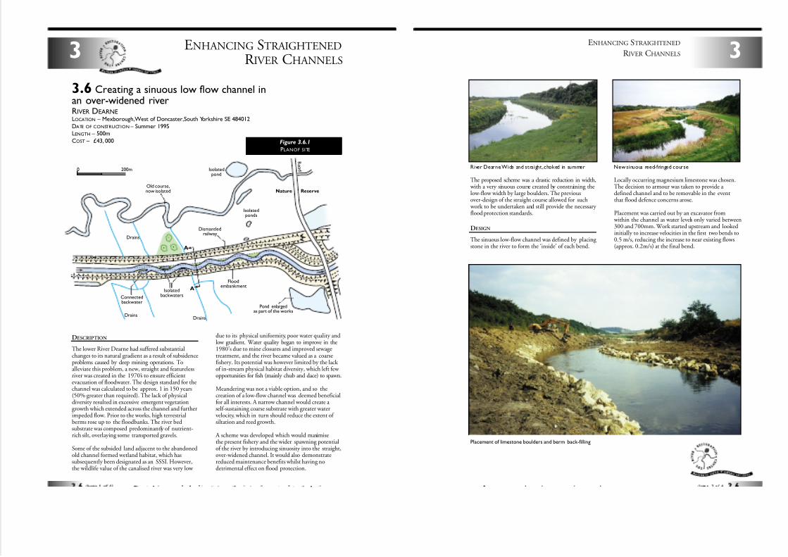
7/27/2019 MAN_mod
http://slidepdf.com/reader/full/manmod 30/84
ENHANCING STRAIGHTENED
R IVER CHANNELS3
3.6 Creating a sinuous low flow channel inan over-widened riverRIVER DEARNELOCATION – Mexborough,West of Doncaster,South Yorkshire SE 484012
DATE OF CONSTRUCTION – Summer 1995LENGTH – 500m
COST – £43, 000
DESCRIPTION
The lower River Dearne had suffered substantialchanges to its natural gradient as a result of subsidenceproblems caused by deep mining operations. Toalleviate this problem, a new, straight and featurelessriver was created in the 1970’s to ensure efficientevacuation of floodwater. The design standard for thechannel was calculated to be approx. 1 in 150 years(50% greater than required). The lack of physicaldiversity resulted in excessive emergent vegetationgrowth which extended across the channel and furtherimpeded flow. Prior to the works, high terrestrialberms rose up to the floodbanks. The river bedsubstrate was composed predominantly of nutrient-rich silt, overlaying some transported gravels.
Some of the subsided land adjacent to the abandonedold channel formed wetland habitat, which hassubsequently been designated as an SSSI. However,the wildlife value of the canalised river was very low
due to its physical uniformity, poor water quality andlow gradient. Water quality began to improve in the1980’s due to mine closures and improved sewagetreatment, and the river became valued as a coarsefishery. Its potential was however limited by the lack of in-stream physical habitat diversity, which left few opportunities for fish (mainly chub and dace) to spawn.
Meandering was not a viable option, and so thecreation of a low-flow channel was deemed beneficialfor all interests. A narrow channel would create a self-sustaining coarse substrate with greater watervelocity, which in turn should reduce the extent of siltation and reed growth.
A scheme was developed which would maximisethe present fishery and the wider spawning potentialof the river by introducing sinuosity into the straight,over-widened channel. It would also demonstratereduced maintenance benefits whilst having nodetrimental effect on flood protection.
Floodembankment
Dismantledrailway
Old course,now isolated
DrainsDrains
Drains
Isolatedbackwaters
Isolatedpond
Isolatedponds
Connectedbackwater
Pond enlargedas part of the works
Nature Reserve
R o a d
A
A
0 200m
Figure 3.6.1
PLANOF SITE
The proposed scheme was a drastic reduction in width, with a very sinuous course created by constraining thelow-flow width by large boulders. The previousover-design of the straight course allowed for such
work to be undertaken and still provide the necessary flood protection standards.
DESIGN
The sinuous low-flow channel was defined by placing stone in the river to form the ‘inside’ of each bend.
Locally occurring magnesium limestone was chosen.The decision to armour was taken to provide a defined channel and to be removable in the eventthat flood defence concerns arose.
Placement was carried out by an excavator from within the channel as water levels only varied between300 and 700mm. Work started upstream and lookedinitially to increase velocities in the first two bends to0.5 m/s, reducing the increase to near existing flows(approx. 0.2m/s) at the final bend.
3
ENHANCING STRAIGHTENED
R IVER CHANNELS
River Dearne.Wide and straight,choked in summer New sinuous reed-fringed course
Placement of limestone boulders and berm back-filling
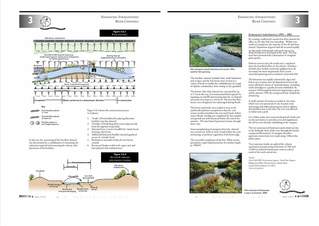
7/27/2019 MAN_mod
http://slidepdf.com/reader/full/manmod 31/84
ENHANCING STRAIGHTENED
R IVER CHANNELS3
In this way the narrowing of the low-flow channel was determined by a combination of estimating thereduction required and measuring the velocity afterplacement of the boulders.
Figure 3.6.2 shows the construction processin 6 phases:
1. ‘Inside’ of bend defined by placing limestoneboulders into the channel;
2. ‘Outside’ of bend shaped by excavating materialfrom the opposite steep bank;
3. Material from 2 used to backfill the ‘inside’ bendforming a low berm;
4. Additional limestone boulder armouring placedon toe of ‘outside’ bend
5. Backwaters excavated within the low bermscreated;
6. Berms and banks seeded with a grass mix andlater planted with standard trees.
Previous channel width
New widthOld railway
embankment
Silt-free bedwith pools developing
Low berm(grass seeded)
Cut and fill
Boulder stonearmouring
Boulder stonearmouring
Floodbank
Deep siltburied
Figure 3.6.3
SECTION A THROUGH
NEW SINUOUS CHANNEL
'Berm' created and compactedbefore backwater created
Old railway embankment
Flood embankment
Backwater
Existing deep silttrapped behind row of boulders
Shortfall of infill material made up bylocally importing from nearby pond enlargement
for habitat enhancement
Key
Stone boulders placed'in' river
Stone boulders placedon bank toe
Numbers appear intext 'design sequence'
Completed Works carried out in a downstream direction In construction
4
3
2
1 6
5
6
1
–
Figure 3.6.2
PLAN OFWORKS
The low-flow channel included three small backwatersand scrapes, and the low berms were created at a variety of levels to enable the establishment of a rangeof riparian communities, from swamp to dry grassland.
The former 10m wide channel was narrowed by upto 5.5m in this way, but maintained flood capacity by equating cut and fill and ensuring that the in-channelstructures were kept to a low level. The new low-flow berms, were designed to be submerged during floods.
The berms and banks were seeded as soon as theearthworks had been completed so that the rootsystem would consolidate the new earth banks before
winter floods. Seeding was completed by late summerand growth was well advanced before the end of theautumn. This also limited potential erosion throughheavy rain.
Some transplanting of emergents from the channel was carried out, both in front of and within the rock armouring, to promote vegetation of the berm edge.
The successful completion of the first 500m sectionprompted a rapid implementation of a similar lengthin 1996/97.
SUBSEQUENT PERFORMANCE 1995 – 2001
By creating a sufficiently narrow low-flow channel theeffect on the silty bed was immediate. Within two
weeks of completion the majority of the silt had beencleared. Deposition of gravel and silt occurred rapidly
on the inside of the bends with pools (up to 2mdeep) having since developed at the apex. The silty areas have promoted the colonisation of marginalplant species.
Fisheries surveys since the works were completedshow the beneficial effect of the scheme. Numbersof chub, dace, barbel, roach and gudgeon have allincreased, but more importantly there is now successful spawning and recruitment of juvenile fish.
The limestone was rapidly colonised by algae andlichen once in place and silt deposition between thestones allowed a variety of waterside plants, including reeds and sedges to quickly become established. By summer 1996 marginal reeds were beginning to grow and by autumn 1996 the reed growth had masked thearmouring.
A small amount of erosion occurred in two areas, which were not protected. In one location rock armouring and willow planting was used to addressthis problem, but in the other the river was allowedto widen into a pool.
Live willow stakes were inserted along both banks andon the new berms to provide cover and supplementthe self-set trees already establishing at the margins.
The two unconnected backwater pools dried out dueto the hydraulic draw of the river through the loosely compacted fill material. To mitigate this effectupstream connections were made using 100mm dia.plastic pipes.
Two years post-works, an audit of the schemereported an annual saving of between £2,500 and£3,000 in reduced maintenance costs as a directresult of the work carried out.
Contact:
Chris Firth OBE, Environment Agency – North East Region,
Ridings Area Office, Phoenix House, Global Road,
Leeds, North Yorkshire, LS11 8PG.
Tel: 0113 244 0191
3
ENHANCING STRAIGHTENED
R IVER CHANNELS
Narrowing increased velocities and created rifflesused for fish spawning
Main channel and backwater5 years on,Summer 2000
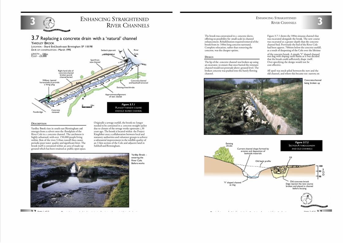
7/27/2019 MAN_mod
http://slidepdf.com/reader/full/manmod 32/84
ENHANCING STRAIGHTENED
R IVER CHANNELS3
DESCRIPTION
Yardley Brook rises in south-east Birmingham andemerges from a culvert onto the floodplain of theRiver Cole in a concrete channel. The catchment ishighly urbanised, with over 150,000 people living
within 2km of the river. Urban run-off thus causesperiodic poor water quality and significant litter. Thebrook itself is contained within an area of made-upground which has been retained as public open space.
Originally a sewage outfall, the brook no longerneeded to be contained in a concrete straight-jacketdue to closure of the sewage works upstream c.30years ago. The brook is located within the ProjectKingfisher area; a collaboration between local andstatutory authorities and volunteer groups to achievea substantial improvement in the wildlife quality of an 11km section of the Cole and adjacent land inSolihull and Birmingham.
Concreteremoved
Spoil fromnew channel
Right hand side of concrete channelbroken up andchannel buried
Setback pipe exit
and stonepitching outfall
Concrete channeland headwall removed
Existing trees/shrubs
Approximate allignmentof new channel
Willows layeredhorizontally to provide
a 'living' plug
River
Cole
Footbridge
A
A
0 10m
3.7 Replacing a concrete drain with a ‘natural’ channelYARDLEY BROOKLOCATION - Shard End,South-east Birmingham SP 118198
DATE OF CONSTRUCTION - March 1995
LENGTH – 100mCOST - £5,000
Figure 3.7.1
PLANOF THENEW COURSE
ANDOLD BURIED CHANNEL
Yardley Brook – entering the
River Cole.Before works
The brook was constrained in a concrete sleeve,offering no possibility for small-scale in-channelenhancement. Rehabilitation required removal of thebrook from its 100m long concrete surround.Complete relocation, rather than removing theconcrete, was the cheaper option.
DESIGN
The lip of the concrete channel was broken up using an excavator, to ensure that once buried the remnantchannel would not protrude above ground level. Thebroken concrete was pushed into the barely flowing channel.
Figure 3.7.1 shows the 100m sinuous channel that was excavated alongside the brook. The new course was excavated at a greater depth than the concretechannel bed. Previously the bed of the River Colehad been approx. 700mm below the concrete outfall,as a result of deepening of the Cole over the lifetime
of the concrete brook. A simple ‘V’ shaped channel was dug with sloping earth banks as it was decidedthat the brook could sufficiently shape itself.Over-specifying the design would not becost-effective.
All spoil was stock-piled between the new and theold channel, and where this became too narrow, on
3
ENHANCING STRAIGHTENED
R IVER CHANNELS
98
99
100
Current channel shape formed byerosion and deposition of
bankside materials
Fill
Old bank profile
'V' shaped channelas dug
Existingshrubs
Old concrete brook Edge nearest the new coursebroken and placed in channel
before burying
m . O .D .
Figure 3.7.2
SECTION A THROUGHNEW
AND OLD CHANNELS
Concrete channel
being broken up
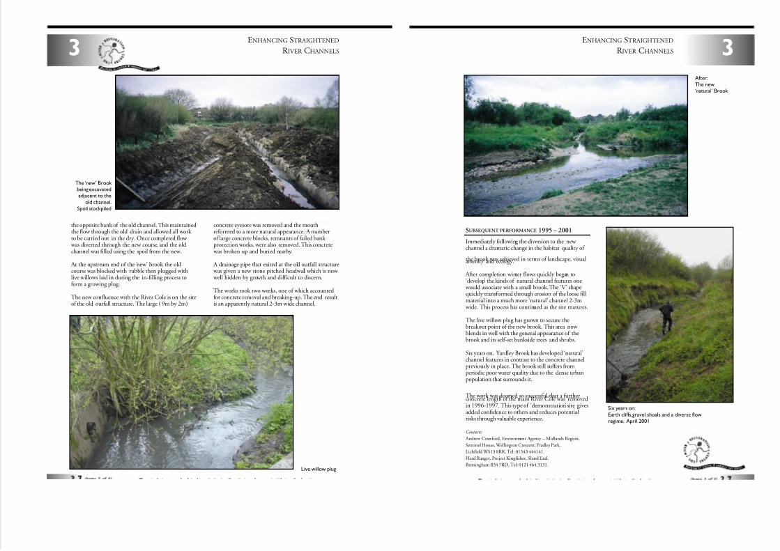
7/27/2019 MAN_mod
http://slidepdf.com/reader/full/manmod 33/84
ENHANCING STRAIGHTENED
R IVER CHANNELS3
the opposite bank of the old channel. This maintainedthe flow through the old drain and allowed all work to be carried out in the dry. Once completed flow
was diverted through the new course, and the oldchannel was filled using the spoil from the new.
At the upstream end of the ‘new’ brook the oldcourse was blocked with rubble then plugged withlive willows laid in during the in-filling process toform a growing plug.
The new confluence with the River Cole is on the siteof the old outfall structure. The large ( 9m by 2m)
concrete eyesore was removed and the mouthreformed to a more natural appearance. A numberof large concrete blocks, remnants of failed bank protection works, were also removed. This concrete
was broken up and buried nearby.
A drainage pipe that exited at the old outfall structure was given a new stone pitched headwall which is now well hidden by growth and difficult to discern.
The works took two weeks, one of which accountedfor concrete removal and breaking-up. The end resultis an apparently natural 2-3m wide channel.
Live willow plug
The ‘new’ Brook being excavatedadjacent to the
old channel.Spoil stockpiled
SUBSEQUENT PERFORMANCE 1995 – 2001
Immediately following the diversion to the new channel a dramatic change in the habitat quality of
the brook was achieved in terms of landscape, visualamenity and ecology.
After completion winter flows quickly began to‘develop’ the kinds of natural channel features one
would associate with a small brook. The ‘V’ shapequickly transformed through erosion of the loose fillmaterial into a much more ‘natural’ channel 2-3m
wide. This process has continued as the site matures.
The live willow plug has grown to secure thebreakout point of the new brook. This area now blends in well with the general appearance of thebrook and its self-set bankside trees and shrubs.
Six years on, Yardley Brook has developed ‘natural’channel features in contrast to the concrete channelpreviously in place. The brook still suffers fromperiodic poor water quality due to the dense urbanpopulation that surrounds it.
The work was deemed so successful that a furtherconcrete length of the main River Cole was removedin 1996-1997. This type of ‘demonstration’ site givesadded confidence to others and reduces potentialrisks through valuable experience.
Contacts:
Andrew Crawford, Environment Agency – Midlands Region,
Sentinel House, Wellington Crescent, Fradley Park,
Lichfield WS13 8RR, Tel: 01543 444141.
Head Ranger, Project Kingfisher, Shard End,
Birmingham B34 7RD, Tel: 0121 464 3131.
3
ENHANCING STRAIGHTENED
R IVER CHANNELS
After:The new‘natural’ Brook
Six years on:
Earth cliffs,gravel shoals and a diverse flowregime. April 2001
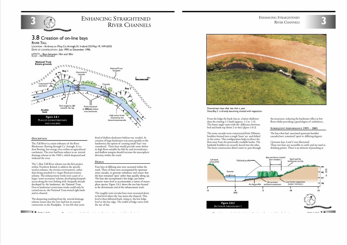
7/27/2019 MAN_mod
http://slidepdf.com/reader/full/manmod 34/84
ENHANCING STRAIGHTENED
R IVER CHANNELS3
DESCRIPTION
The Tall River is a main tributary of the RiverBlackwater, flowing through Co. Armagh. It is a slow flowing, low energy river within an agriculturalcatchment. The river had been subject to an arterialdrainage scheme in the 1960’s, which deepened and
widened the river.
The 1.2km Tall River scheme was the first project within Northern Ireland to address the specificneed to enhance the riverine environment, ratherthan being attached to a larger flood preventionscheme. The enhancement works were a part of a larger ‘water recreation’ scheme, developing footpathaccess along the river linking with footpaths already developed by the landowner, the National Trust.Due to landowner restrictions works could only becarried out on the National Trust owned right bank and in-channel.
The deepening resulting from the arterial drainagescheme meant that the river had lost its naturalconnection to the floodplain. It was felt that some
kind of shallow slackwater habitat was needed. Ascreation of large backwaters was unacceptable to thelandowner, the option of creating small ‘bays’ wasconsidered. These bays would provide some shelterin high flows suitable for fish fry and invertebrates,and shallow margins should increase the macrophytediversity within the reach.
DESIGN
Four bays of differing sizes were excavated within thereach. Three of these were accompanied by upstreamstone cascades, to generate turbulence and ensure thatthe bays remained ‘open’ rather than quickly silting up.The bays also incorporated a low ledge, just below summer water level to accommodate a variety of macro-phyte species. Figure 3.8.1 shows the two bays locatedat the downstream end of the enhancement reach.
The roughly semi-circular bays were excavated downto bed level where the bay meets the channel. Thislevel is then followed back, rising to the low ledgelevel at the bay edge. The width of ledge varies withthe size of bay.
3.8 Creation of on-line baysRIVER TALLLOCATION - Ardress, nr.Moy, Co.Armagh,N. Ireland.OS Map 19, H916555
DATE OF CONSTRUCTION - July 1995 to December 1996
LENGTH – Bays between 10m and 30mCOST - NOTAVAILABLE
Colonisedwet berm
Pools sustainedat 400mm below
river bed levels
High water levelsretained by the
downstream cascade
Cascade
Flow angled at 30°towards the bay
Asymmetriccascade
National TrustfootpathBay 1
Arablefield
National TrustEstate grounds
Bay 2
0 10m
A
A
Figure 3.8.1
PLAN OF DOWNSTREAM BAYS
AND CASCADES
From the ledge the bank rises at a batter shallowerthan the existing 1:1 bank (approx. 1:2 to 1:3).The batter angle varies with the difference betweenbed and bank top (from 2 to 4m) ( figure 3.8.2 ).
The stone cascades were constructed from 500mm+boulders formed into a rough ‘loose’ arc and dishedin the centre. This configuration helps to direct theflow away from the potentially erodable banks. Thebankside boulders are securely keyed into the sides.The loose construction allows water to pass through
the structures, reducing the backwater effect at low flows whilst providing a good degree of turbulence.
SUBSEQUENT PERFORMANCE 1995 – 2001
The bays that had associated upstream bouldercascades have remained ‘open’ to differing degrees.
Upstream bays 3 and 4 (not illustrated)These two bays are accessible to cattle and are used asdrinking points. There is an element of poaching at
3
ENHANCING STRAIGHTENED
R IVER CHANNELS
Spoil used bylandowner on site
2m wet berm created(bur-reed,etc.)Old bank profile
As dug profileSilt acretion
and berm extension
Left bank untouched
Low herby wegetation(water mint,etc.)
Summer
water level
(m)
96
0-5 5 10 15
98
99
97 m
. O . D .
Figure 3.8.2
SECTION A THROUGH BAY 1
Downstream bays after less than a year.Note:Bay 2 is already becoming choked with vegetation
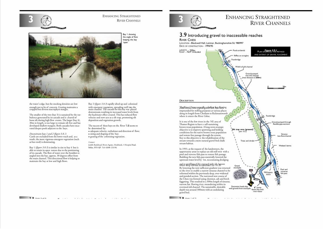
7/27/2019 MAN_mod
http://slidepdf.com/reader/full/manmod 35/84
ENHANCING STRAIGHTENED
R IVER CHANNELS3
the water’s edge, but the stocking densities are low
enough not to be of concern. Grazing maintains a cropped but diverse macrophyte margin.
The smaller of the two (bay 3) is sustained by the tur-bulence generated by its cascade and is cleared of loose silt during high flow events. The larger (bay 4),30m in length, is too large to remain silt free and hasdeveloped shallow margins. Both cascades have exca-vated deeper pools adjacent to the bays.
Downstream bays 1 and 2 (figure 3.8.1)Cattle are excluded from the lower reach and, as a result, the more vigorous emergent vegetation (suchas bur-reed) is dominating.
Bay 1 ( figure 3.8.1) is similar in size to bay 4 but isable to retain its open nature due to the positioning of its cascade. The flow of water over the boulders isangled into the bay, approx. 30 degrees offset fromthe main channel. This directional flow is helping tomaintain the bay at low and high flows.
Bay 2 ( figure 3.8.1) rapidly silted up and colonised
with emergent vegetation, spreading well into themain channel. The cascade for this bay was placeddownstream, resulting in increased water levels fromthe backwater effect created. This has reduced flow velocity and now acts as a silt trap, promoting siltdeposition and vegetation growth.
The success of these bays on the River Tall seems tobe determined by:
• adequate velocity, turbulence and direction of flow;
• sizing and shaping of the bay;
• grazing of the colonising vegetation.
Contact:
Judith Bankhead, Rivers Agency, Hydebank, 4 Hospital Road,
Belfast, BT8 8JP. Tel: 02890 253196.
Bay 1 showingthe angle of flow
keeping the bay‘open’
ENHANCING STRAIGHTENED
R IVER CHANNELS3
DESCRIPTION
The River Chess, naturally a shallow fast flowing chalk stream with a good gravel bed, had beenimpounded for milling purposes at various placesalong its length from Chesham to Rickmansworth
where it enters the River Colne.
It is one of the few rivers in the NE area of Thames Region to have a self-sustaining brown trout population. A long-term strategicobjective is to improve spawning and holding conditions for the native brown trout populationand restore free passage through the system.Key to this objective is the rehabilitation of thestream towards a more natural gravel-bed chalk stream habitat.
In 1993, at the request of the landowners, theopportunity arose to replace an old mill weir with a pool and traverse fish-pass to restore fish passage.Building the new fish-pass essentially lowered theupstream water level by 1m, necessitating dredging
and re-profiling of the exposed wide silt lagoon where deep silt had accumulated (see 10.3).By lowering the weir sufficient gradient was returnedto the river to enable a narrow sinuous channel to bereformed within the previously deep, over-widenedand ponded section. The narrowed new course of the Chess was formed using chestnut, ash and birchfaggoting. This resulted in a 300m length of sinuous,narrow, fast flowing river, meandering within itsoversized old channel. The sustainable, desirabledepth was around 300mm with an undulating gravel bed.
3.9 lntroducing gravel to inaccessible reachesRIVER CHESSLOCATION - Blackwell Hall, Latimer, Buckinghamshire SU 980997
DATE OF CONSTRUCTION - 1994/95
LENGTH – 250mCOST - NOT AVAILABLE
Figure 3.9.1PLAN SHOWING THE METHOD
AND EXTENT OF GRAVEL PLACEMENT
0 30m
Gravel pumped throughflexible pipe sections
Sinuouslow-flow channel
Wetland berms
Pool andtraversefish pass
Mill bypasssluice
Gravelstockpile
Excavator loads skipwith gravels from stockpile 6" pump
feeds skip withriver water
Trees and shrubs
Silt trap area (grassed)(see 10.3)
Footbridge
Footbridge
Gravel pumpedinto the channel
(max distance is 250m)
Width of old channel
Riffles on straights
Pools on bends
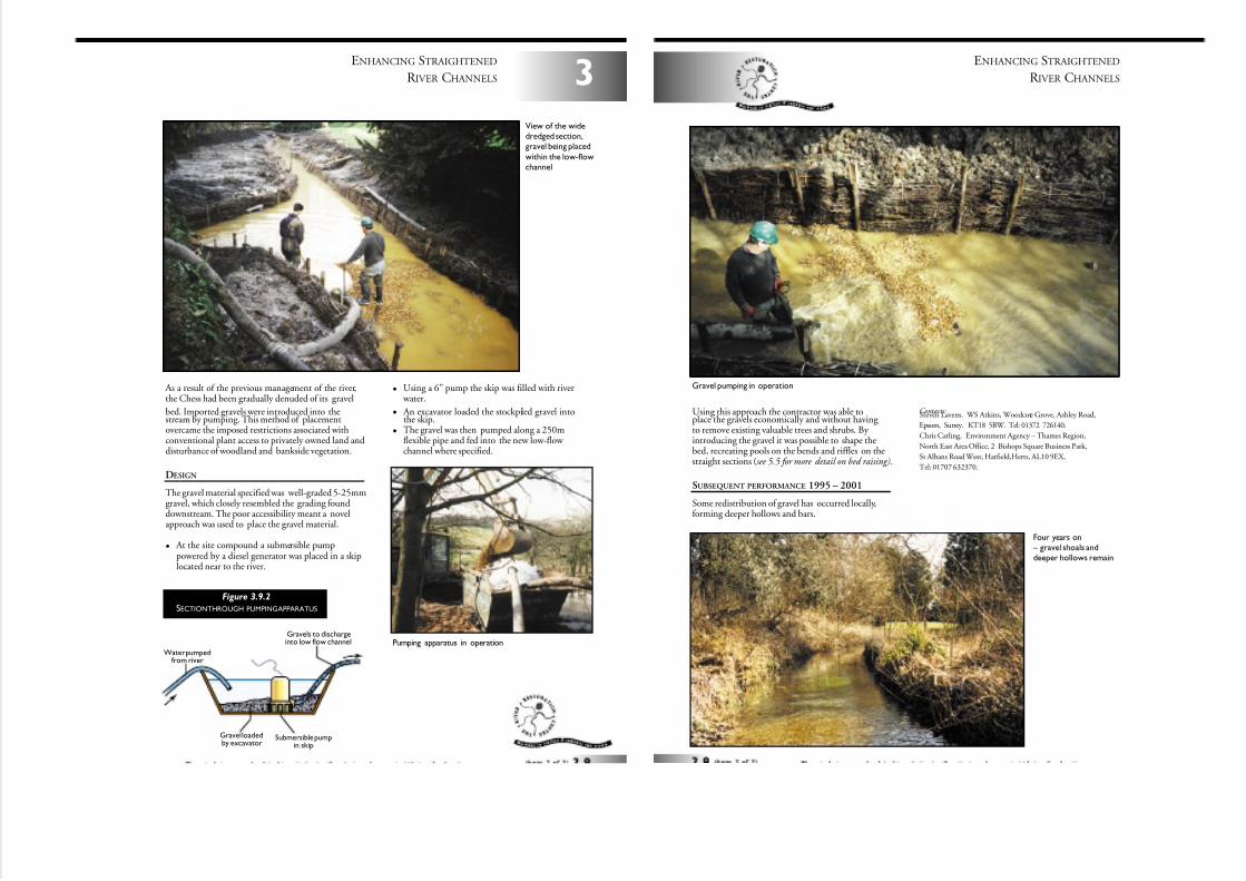
7/27/2019 MAN_mod
http://slidepdf.com/reader/full/manmod 36/84
As a result of the previous management of the river,the Chess had been gradually denuded of its gravel
bed. Imported gravels were introduced into thestream by pumping. This method of placementovercame the imposed restrictions associated withconventional plant access to privately owned land anddisturbance of woodland and bankside vegetation.
DESIGN
The gravel material specified was well-graded 5-25mmgravel, which closely resembled the grading founddownstream. The poor accessibility meant a novelapproach was used to place the gravel material.
• At the site compound a submersible pumppowered by a diesel generator was placed in a skiplocated near to the river.
• Using a 6” pump the skip was filled with river water.
• An excavator loaded the stockpiled gravel intothe skip.
• The gravel was then pumped along a 250mflexible pipe and fed into the new low-flow channel where specified.
3
ENHANCING STRAIGHTENED
R IVER CHANNELS
Gravels to dischargeinto low flow channel
Gravel loadedby excavator
Submersible pumpin skip
Water pumpedfrom river
Figure 3.9.2
SECTIONTHROUGH PUMPINGAPPARATUS
View of the widedredged section,gravel being placed
within the low-flowchannel
Pumping apparatus in operation
Using this approach the contractor was able toplace the gravels economically and without having to remove existing valuable trees and shrubs. By introducing the gravel it was possible to shape thebed, recreating pools on the bends and riffles on thestraight sections (see 5.5 for more detail on bed raising).
SUBSEQUENT PERFORMANCE 1995 – 2001
Some redistribution of gravel has occurred locally,forming deeper hollows and bars.
Contacts:Steven Lavens. WS Atkins, Woodcote Grove, Ashley Road,
Epsom, Surrey. KT18 5BW. Tel: 01372 726140.
Chris Catling. Environment Agency – Thames Region,
North East Area Office, 2 Bishops Square Business Park,
St Albans Road West, Hatfield,Herts, AL10 9EX,
Tel: 01707 632370.
ENHANCING STRAIGHTENED
R IVER CHANNELS
Gravel pumping in operation
Four years on – gravel shoals anddeeper hollows remain
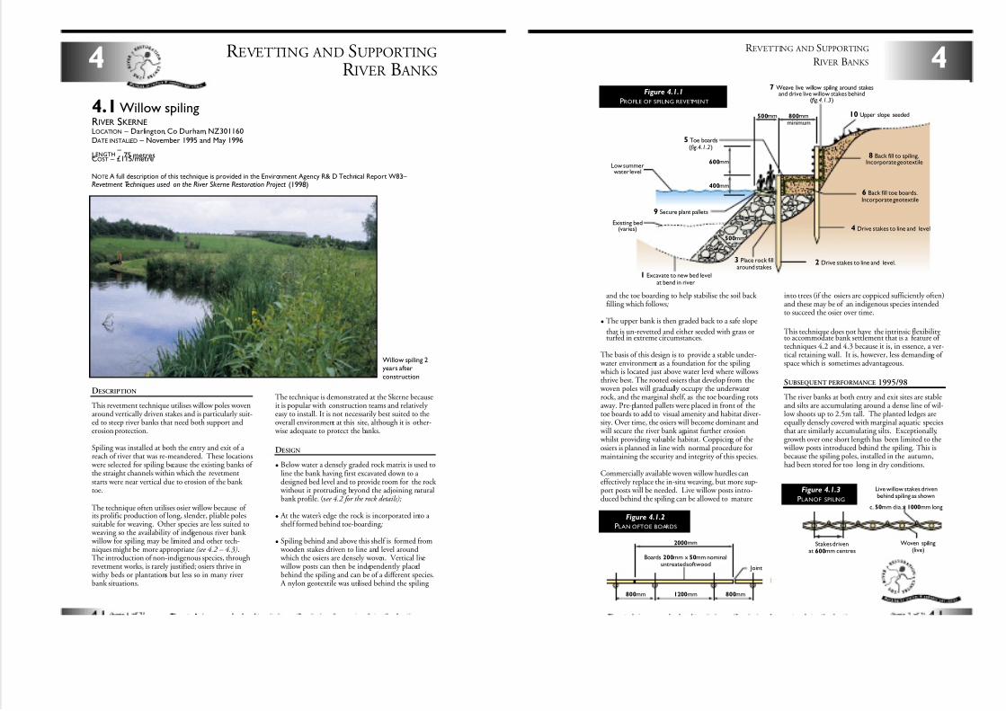
7/27/2019 MAN_mod
http://slidepdf.com/reader/full/manmod 37/84
DESCRIPTION
This revetment technique utilises willow poles wovenaround vertically driven stakes and is particularly suit-ed to steep river banks that need both support anderosion protection.
Spiling was installed at both the entry and exit of a reach of river that was re-meandered. These locations
were selected for spiling because the existing banks of the straight channels within which the revetmentstarts were near vertical due to erosion of the bank toe.
The technique often utilises osier willow because of its prolific production of long, slender, pliable polessuitable for weaving. Other species are less suited to
weaving so the availability of indigenous river bank willow for spiling may be limited and other tech-niques might be more appropriate (see 4.2 – 4.3).The introduction of non-indigenous species, throughrevetment works, is rarely justified; osiers thrive in
withy beds or plantations but less so in many riverbank situations.
R EVETTING AND SUPPORTING
R IVER B ANKS4
4.1Willow spilingRIVER SKERNELOCATION – Darlington, Co Durham, NZ301160DATE INSTALLED – November 1995 and May 1996
LENGTH–
75 metresCOST – £115/metre
NOTE: A full description of this technique is provided in the Environment Agency R& D Technical Report W83: – Revetment Techniques used on the River Skerne Restoration Project (1998)
Willow spiling 2years after
construction
The technique is demonstrated at the Skerne becauseit is popular with construction teams and relatively easy to install. It is not necessarily best suited to theoverall environment at this site, although it is other-
wise adequate to protect the banks.
DESIGN
• Below water a densely graded rock matrix is used toline the bank having first excavated down to a designed bed level and to provide room for the rock
without it protruding beyond the adjoining naturalbank profile. (see 4.2 for the rock details);
• At the water’s edge the rock is incorporated into a shelf formed behind toe-boarding ;
• Spiling behind and above this shelf is formed from wooden stakes driven to line and level around which the osiers are densely woven. Vertical live willow posts can then be independently placedbehind the spiling and can be of a different species.
A nylon geotextile was utilised behind the spiling
and the toe boarding to help stabilise the soil back filling which follows;
• The upper bank is then graded back to a safe slope
that is un-revetted and either seeded with grass orturfed in extreme circumstances.
The basis of this design is to provide a stable under- water environment as a foundation for the spiling which is located just above water level where willowsthrive best. The rooted osiers that develop from the
woven poles will gradually occupy the underwaterrock, and the marginal shelf, as the toe boarding rotsaway. Pre-planted pallets were placed in front of thetoe boards to add to visual amenity and habitat diver-sity. Over time, the osiers will become dominant and
will secure the river bank against further erosion whilst providing valuable habitat. Coppicing of theosiers is planned in line with normal procedure formaintaining the security and integrity of this species.
Commercially available woven willow hurdles caneffectively replace the in-situ weaving, but more sup-port posts will be needed. Live willow posts intro-duced behind the spiling can be allowed to mature
into trees (if the osiers are coppiced sufficiently often)and these may be of an indigenous species intendedto succeed the osier over time.
This technique does not have the intrinsic flexibility to accommodate bank settlement that is a feature of techniques 4.2 and 4.3 because it is, in essence, a ver-tical retaining wall. It is, however, less demanding of space which is sometimes advantageous.
SUBSEQUENT PERFORMANCE 1995/98
The river banks at both entry and exit sites are stableand silts are accumulating around a dense line of wil-low shoots up to 2.5m tall. The planted ledges areequally densely covered with marginal aquatic speciesthat are similarly accumulating silts. Exceptionally,growth over one short length has been limited to the
willow posts introduced behind the spiling. This isbecause the spiling poles, installed in the autumn,had been stored for too long in dry conditions.
800mmminimum
500mm
600mm
400mm
500mm
1 Excavate to new bed levelat bend in river
2 Drive stakes to line and level.3 Place rock fillaround stakes
4 Drive stakes to line and level
5 Toe boards(fig.4.1.2)
6 Back fill toe boards.Incorporate geotextile
7 Weave live willow spiling around stakesand drive live willow stakes behind
(fig.4.1.3)
8 Back fill to spiling.Incorporate geotextile
9 Secure plant pallets
10 Upper slope seeded
Existing bed(varies)
Low summerwater level
4
R EVETTING AND SUPPORTING
R IVER B ANKS
Figure 4.1.1
PROFILE OF SPILING REVETMENT
1200mm
2000mm
800mm800mm
Boards 200mm x 50mm nominaluntreated softwood
Joint
Stakes drivenat 600mm centres
Woven spiling(live)
Live willow stakes drivenbehind spiling as shown
c. 50mm dia.x 1000mm long
Figure 4.1.3
PLANOF SPILING
Figure 4.1.2
PLAN OFTOE BOARDS
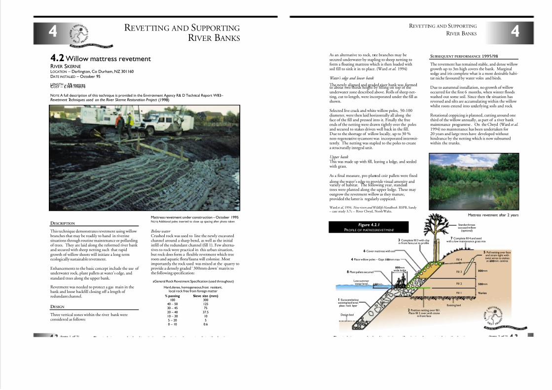
7/27/2019 MAN_mod
http://slidepdf.com/reader/full/manmod 38/84
DESCRIPTION
This technique demonstrates revetment using willow branches that may be readily to hand in riverinesituations through routine maintenance or pollarding of trees. They are laid along the reformed river bank and secured with sheep netting such that rapidgrowth of willow shoots will initiate a long termecologically sustainable revetment.
Enhancements to the basic concept include the use of underwater rock, plant pallets at water’s edge, andstandard trees along the upper bank.
Revetment was needed to protect a gas main in thebank and loose backfill closing off a length of redundant channel.
DESIGN
Three vertical zones within the river bank wereconsidered as follows:
R EVETTING AND SUPPORTING
R IVER B ANKS4
4.2 Willow mattress revetmentRIVER SKERNELOCATION – Darlington, Co Durham, NZ 301160DATE INSTALLED – October 95
LENGTH – 59 metresCOST – £164 /metre
Mattress revetment under construction – October 1995NOTE: Additional poles inserted to close up spacing after photo taken
aGeneral Rock Revetment Specification (used throughout)
Hard,dense, homogeneous,frost resistant,local rock free from foreign matter
% passing
10040 – 5030 – 45
20 – 4010 – 305 – 200 – 10
Sieve size (mm)
30012575
37.5105
0.6
NOTE: A full description of this technique is provided in the Environment Agency R& D Technical Report W83:– Revetment Techniques used on the River Skerne Restoration Project (1998)
Below water Crushed rock was used to line the newly excavatedchannel around a sharp bend, as well as the initialinfill of the redundant channel (fill 1). Few alterna-tives to rock were practical in this urban situation,but rock does form a flexible revetment which treeroots and aquatic flora/fauna will colonise. Mostimportantly, the rock used was mixed at the quarry toprovide a densely graded ‘ 300mm down’ matrix tothe following specification: Fill 3
Fill 4
Fill 2
Fill 1
800mmwide ledge
150mm
500mm
Standard treessucceed willow
(optional)
800mm
500mm
Varies
Existing bed
Low summerwater level
1 Excavate belowexisting bed level,place rock layer
2 Position netting over fill1.Place fill 2 over,with stone
in front face
8 Plant pallets secured
3 Complete fill 3 with clayin front face,cut to profile
6 Cover mattress with soil
7 Complete fill 4 and seedwith a low maintenance grass mix
5 Pull netting over faceand strain tight withtwist wires to stakesat 600mm centres4 Place willow poles – Gaps 100mm max
Design bed
4
R EVETTING AND SUPPORTING
R IVER B ANKS
Figure 4.2.1
PROFILE OF MATRESSREVETMENT
As an alternative to rock, tree branches may besecured underwater by stapling to sheep netting toform a floating mattress which is then loaded withsoil fill to sink it in to place. (Ward et al . 1994)
Water’s edge and lower bank
The newly aligned and graded river bank was formedto about two thirds height by filling on top of theunderwater zone described above. Rolls of sheep net-ting, cut to length, were incorporated under the fill asshown.
Selected live crack and white willow poles, 50-100diameter, were then laid horizontally all along theface of the fill and pressed into it. Finally the freeends of the netting were drawn tightly over the polesand secured to stakes driven well back in the fill.Due to the shortage of willow locally, up to 30 %non-regenerative sycamore was incorporated intermit-tently. The netting was stapled to the poles to createa structurally integral unit.
Upper bank This was made up with fill, leaving a ledge, and seeded
with grass.
As a final measure, pre-planted coir pallets were fixed
along the water’s edge to provide visual amenity andvariety of habitat. The following year, standardtrees were planted along the upper ledge. These may outgrow the revetment willow as they mature,provided the latter is regularly coppiced.
Ward et al , 1994. New rivers and Wildlife Handbook . RSPB, Sandy – case study 3.7c – River Clwyd, North Wales.
Mattress revetment after 2 years
SUBSEQUENT PERFORMANCE 1995/98
The revetment has remained stable, and dense willow growth up to 3m high covers the bank. Marginalsedge and iris complete what is a most desirable habi-tat niche favoured by water voles and birds.
Due to autumnal installation, no growth of willow occurred for the first 6 months, when winter floods
washed out some soil. Since then the situation hasreversed and silts are accumulating within the willow
whilst roots extend into underlying soils and rock.
Rotational coppicing is planned, cutting around onethird of the willow annually, as part of a river bank maintenance programme . On the Clwyd (Ward et al.1994) no maintenance has been undertaken for20 years and large trees have developed withouthindrance by the netting which is now subsumed
within the trunks.
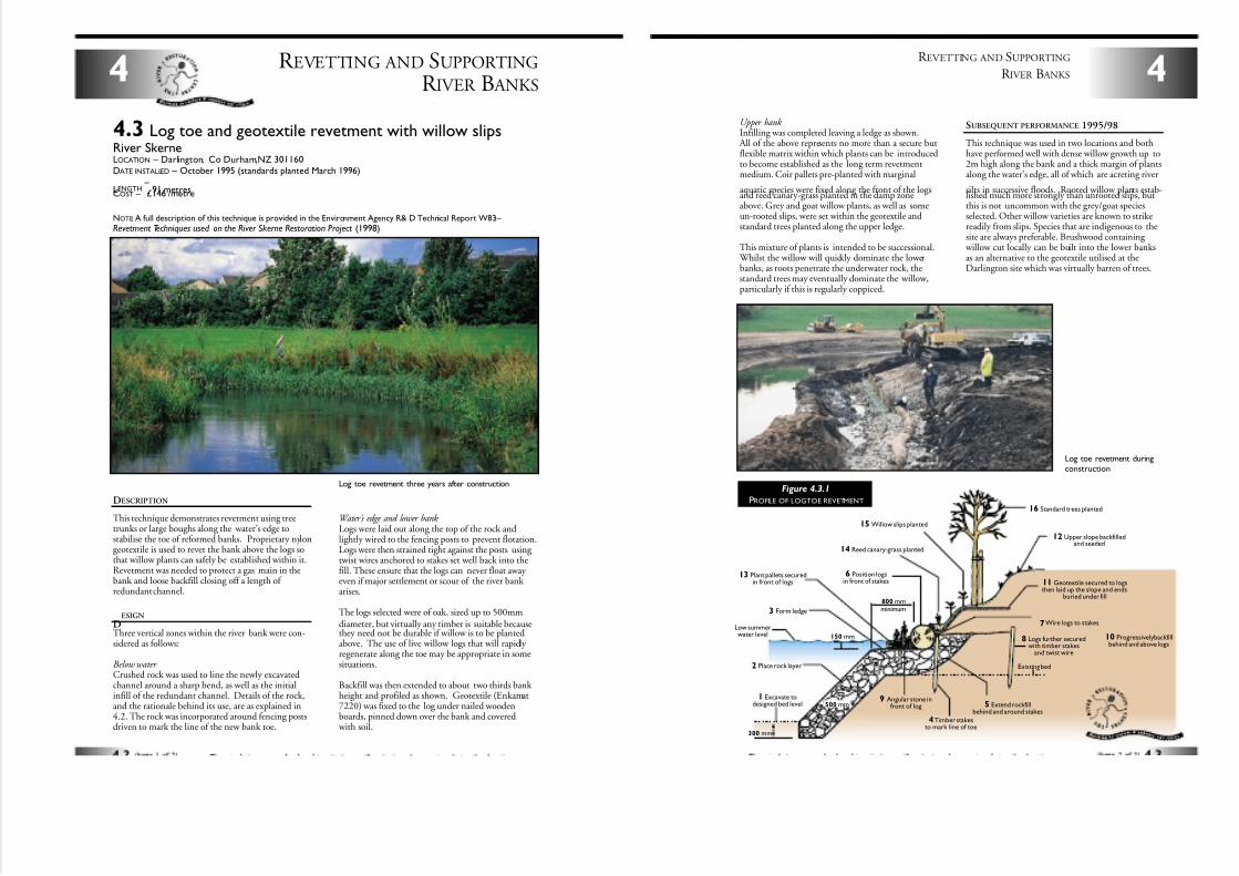
7/27/2019 MAN_mod
http://slidepdf.com/reader/full/manmod 39/84
DESCRIPTION
This technique demonstrates revetment using treetrunks or large boughs along the water’s edge tostabilise the toe of reformed banks. Proprietary nylongeotextile is used to revet the bank above the logs sothat willow plants can safely be established within it.Revetment was needed to protect a gas main in thebank and loose backfill closing off a length of redundant channel.
R EVETTING AND SUPPORTING
R IVER B ANKS4
4.3 Log toe and geotextile revetment with willow slipsRiver SkerneLOCATION – Darlington, Co Durham,NZ 301160DATE INSTALLED – October 1995 (standards planted March 1996)
LENGTH–
91 metresCOST – £146 /metre
Log toe revetment three years after construction
NOTE: A full description of this technique is provided in the Environment Agency R& D Technical Report W83: –
Revetment Techniques used on the River Skerne Restoration Project (1998)
Water’s edge and lower bank Logs were laid out along the top of the rock andlightly wired to the fencing posts to prevent flotation.Logs were then strained tight against the posts using twist wires anchored to stakes set well back into thefill. These ensure that the logs can never float away even if major settlement or scour of the river bank arises.
The logs selected were of oak, sized up to 500mmdiameter, but virtually any timber is suitable becausethey need not be durable if willow is to be plantedabove. The use of live willow logs that will rapidly regenerate along the toe may be appropriate in somesituations.
Backfill was then extended to about two thirds bank height and profiled as shown. Geotextile (Enkamat7220) was fixed to the log under nailed woodenboards, pinned down over the bank and covered
with soil.
DESIGN
Three vertical zones within the river bank were con-sidered as follows:
Below water Crushed rock was used to line the newly excavatedchannel around a sharp bend, as well as the initialinfill of the redundant channel. Details of the rock,and the rationale behind its use, are as explained in4.2. The rock was incorporated around fencing postsdriven to mark the line of the new bank toe.
Low summerwater level
800 mmminimum
150 mm
500 mm
300 mm
1 Excavate todesigned bed level
Existing bed2 Place rock layer
3 Form ledge
4Timber stakesto mark line of toe
5 Extend rockfillbehind and around stakes
7Wire logs to stakes
8 Logs further securedwith timber stakes
and twist wire
10 Progressively backfillbehind and above logs
11 Geotextile secured to logsthen laid up the slope and ends
buried under fill
12 Upper slope backfilledand seeded
16 Standard trees planted
15 Willow slips planted
14 Reed canary-grass planted
13 Plant pallets securedin front of logs
6 Position logsin front of stakes
9 Angular stone infront of log
Upper bank Infilling was completed leaving a ledge as shown.
All of the above represents no more than a secure butflexible matrix within which plants can be introducedto become established as the long term revetmentmedium. Coir pallets pre-planted with marginal
aquatic species were fixed along the front of the logsand reed canary-grass planted in the damp zoneabove. Grey and goat willow plants, as well as someun-rooted slips, were set within the geotextile andstandard trees planted along the upper ledge.
This mixture of plants is intended to be successional. Whilst the willow will quickly dominate the lowerbanks, as roots penetrate the underwater rock, thestandard trees may eventually dominate the willow,particularly if this is regularly coppiced.
4
R EVETTING AND SUPPORTING
R IVER B ANKS
Figure 4.3.1
PROFILE OF LOGTOE REVETMENT
Log toe revetment duringconstruction
SUBSEQUENT PERFORMANCE 1995/98
This technique was used in two locations and bothhave performed well with dense willow growth up to2m high along the bank and a thick margin of plantsalong the water’s edge, all of which are acreting river
silts in successive floods. Rooted willow plants estab-lished much more strongly than unrooted slips, butthis is not uncommon with the grey/goat speciesselected. Other willow varieties are known to strikereadily from slips. Species that are indigenous to thesite are always preferable. Brushwood containing
willow cut locally can be built into the lower banksas an alternative to the geotextile utilised at theDarlington site which was virtually barren of trees.
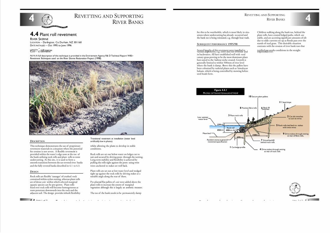
7/27/2019 MAN_mod
http://slidepdf.com/reader/full/manmod 40/84
DESCRIPTION
This technique demonstrates the use of proprietary revetment materials in a situation where the potentialfor erosion is not severe. A flexible revetment isprovided within the water’s edge zone at the toe of the bank utilising rock rolls and plant rolls to resistundercutting. At this site, it is used to form a smooth transition between the un-reveted river banks
and the fully reveted banks described in 4.1 to 4.3.
DESIGN
Rock rolls are flexible ‘sausages’ of crushed rock contained within nylon netting, whereas plant rollsare of dense coir within which selected marginalaquatic species can be pre-grown. Plant rollsfixed over rock rolls will become homogeneous asroots penetrate downwards into the rock and theadjacent soil. The design provides inbuilt flexibility
whilst allowing the plants to develop in stableconditions.
Rock rolls are set out below water on ledges cut tosuit and secured by driving posts through the netting.Long term stability and flexibility is achieved by pulling the rolls tight against the posts using twist
wires anchored to stakes set well back.
Plant rolls are set out at low water level and wedgedtight up against the rock rolls by driving stakes at a suitable angle along the rear of these.
Pre-planted flat pallets of coir were added above theplant rolls to increase the extent of marginalvegetation although this is largely an aesthetic measure.
The toe of the bank needs to be permanently damp
R EVETTING AND SUPPORTING
R IVER B ANKS4
4.4 Plant roll revetmentRIVER SKERNELOCATION – Darlington, Co Durham, NZ 301160
DATE INSTALLED – Oct 1995 to June 1996
LENGTH–
119 metresCOST – £130/metre
Transitonal revetment at installation (water levelartificially low in photo)
NOTE: A full description of this technique is provided in the Environment Agency R& D Technical Report W83: – Revetment Techniques used on the River Skerne Restoration Project (1998)
150mm
450mm
1500mm600mm
1 Cut ledge profile
2 Cut slit trenchesto suit tie wires
3 Place rock rolls
4 Drive stakes through nettingat rear of rock rolls
5 Rock rolls tied back to stakeswith twist wires
8 Position fibre rolls
7 Gravel backfillbehind rock rolls
6 Back filltrenches
11 Seed slope
10 Secure plant pallets
9 Drive stakes through nettingat rear of fibre rolls,
Rock roll400mm dia
Mean bed
Random stone as generalrevetment specification
Low summerwater level
for this to be worthwhile, which is most likely in situ-ations where undercutting has already occurred andthe bank toe is being reinstated, e.g. through boat wash.
SUBSEQUENT PERFORMANCE 1995/98
Several lengths of this revetment were installed invarious alignments, e.g. entry and exit of bends andin backwaters. All have established well with reedcanary-grass proving to be the most dominant plantbest suited to the habitat niche created. Growth isgenerally limited to within 500mm of river level
where the bank is damp. Above this the pallets havebeen colonised by ruderial plants such as himalayanbalsam, which is being controlled by mowing beforeseed heads form.
Children walking along the bank toe, behind theplant rolls, have created ledged paths, which arestable, and are accreting significant amounts of siltdue to eddy currents set up as floods pass over thestands of reed grass. This desirable situationcontrasts with the erosion of river bank toes that
typified pre-works conditions in the straighttrapezoidal river.
4
R EVETTING AND SUPPORTING
R IVER B ANKS
Figure 4.4.1
PROFILE OFTRANSITIONALREVETMENT
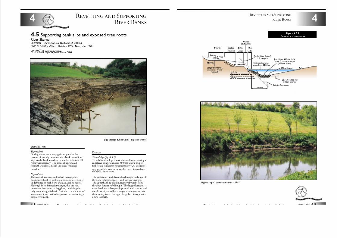
7/27/2019 MAN_mod
http://slidepdf.com/reader/full/manmod 41/84
DESCRIPTION
Slipped slope During works, water seepage from gravel at thebottom of a newly excavated river bank caused it toslip. As the bank was close to bunded industrial fill,repair was necessary. The route of a proposedfootpath was also at risk if this bank remained
unstable.
Exposed roots The roots of a mature willow had been exposedduring river bank re-profiling works and were being undermined by high flows and damaged by people.
Although in no immediate danger, this tree hadbecome an important resting place, providing theonly shade along this bank. Positioned on the apex of a meander, it was decided to protect the roots using a simple revetment.
DESIGN
Slipped slope(fig. 4.5.1)To stabilise this slope it was reformed incorporating a rock layer using stone sized 300mm ‘down’ as speci-fied for use on nearby revetments (see 4.2). Ledges of
varying widths were introduced at metre intervals upthe slope, above water.
The underwater rock layer added weight to the toe of the slope to help support it and was free draining.The upper bank re-profiling removed weight fromthe slope further stabilising it. The ledge closest to
water level was subsequently planted with trees to addvisual amenity as well as a longer term revetment via their root system. The upper ledge later incorporateda new footpath.
R EVETTING AND SUPPORTING
R IVER B ANKS4
4.5 Supporting bank slips and exposed tree rootsRiver SkerneLOCATION – Darlington,Co Durham,NZ 301160
DATE OF CONSTRUCTION – October 1995 / November 1996
LENGTH–
40 metres,9 metresCOST – Bank Slip £3k,Tree Roots £400
Slipped slope during work – September 1995
E x i s t i n g g r o u n d .ap p r o x .
4mmin
39.0m lowest
Lowest bed as dug38.7m approx.
Estimated summerwater level 40.33m
Rock layer 400mm thick Stone as revetment spec
(300mm down)
As dug (face slipped)1:1 steepest
Ledge for machineaccess and future
footpath
4m min Varies
(3mmin)
2.0m
Ledge
Sandy clay
Clay with gravelClaySilty sand
42.50m
Varies(1.0m min)
1.0m
Ledge
1 : 2 s t e e p e s t 1 : 1
1 : 2
1 : 5
41.20m max.
Existing face as dug
4
R EVETTING AND SUPPORTING
R IVER B ANKS
Figure 4.5.1
PROFILE OF SLIPPED SLOPE
Slipped slope 2 years after repair – 1997
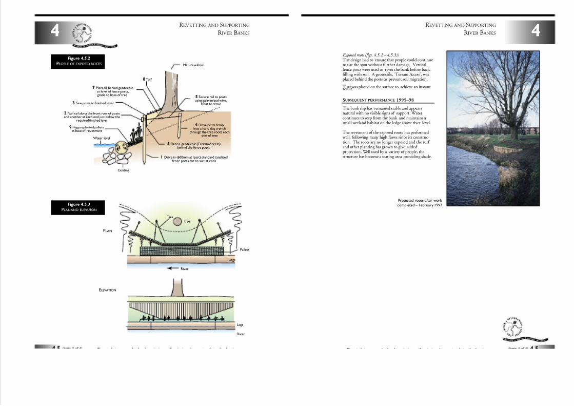
7/27/2019 MAN_mod
http://slidepdf.com/reader/full/manmod 42/84
R EVETTING AND SUPPORTING
R IVER B ANKS4
Ties
Tree
Logs
Logs
Pallets
River
River
Figure 4.5.3
PLANAND ELEVATION
Mature willow
2 Nail rail along the front row of postsand another at each end just below the
required finished level
3 Saw posts to finished level
4 Drive posts firmlyinto a hand dug trench
through the tree roots eachside of tree
5 Secure rail to postsusing galavanised wire,
twist to strain
7 Place fill behind geotextileto level of fence posts,grade to base of tree
8Turf
9 Peg preplanted palletsat base of revetment
6 Place a geotextile (Terram Access)behind the fence posts
1 Drive in (600mm at least) standard tanalisedfence posts,cut to suit at ends
Water level
Existing
Figure 4.5.2
PROFILE OF EXPOSED ROOTS
PLAN
ELEVATION
4
R EVETTING AND SUPPORTING
R IVER B ANKS
Protected roots after work completed – February 1997
Exposed roots (figs. 4.5.2 – 4.5.3))The design had to ensure that people could continueto use the spot without further damage. Verticalfence posts were used to revet the bank before back-filling with soil. A geotextile, ‘Terram Access’, wasplaced behind the posts to prevent soil migration.
Turf was placed on the surface to achieve an instantresult.
SUBSEQUENT PERFORMANCE 1995–98
The bank slip has remained stable and appearsnatural with no visible signs of support. Watercontinues to seep from the bank and maintains a small wetland habitat on the ledge above river level.
The revetment of the exposed roots has performed well, following many high flows since its construc-tion. The roots are no longer exposed and the turf and other planting has grown to give addedprotection. Well used by a variety of people, thestructure has become a seating area providing shade.
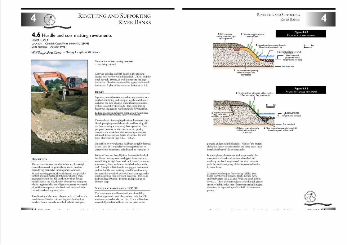
7/27/2019 MAN_mod
http://slidepdf.com/reader/full/manmod 43/84
Coir was installed on both banks at the crossing located mid way between the ford (ch. 280m) and thestock bay (ch. 100m), as well as opposite the largebackwater. Hurdles were installed opposite the smallbackwater. A plan of the reach can be found in 1.2.
DESIGN
A primary consideration was achieving a satisfactory method of infilling and compacting the old channelsuch that the new channel could then be excavated
within reasonably stable soils. The complicating factor was the need to work around a flowing river.
Failure to achieve sufficient compaction would haverequired more robust and costly revetments.
Two methods of managing the river flows were com-bined; pumping round the works and blocking off the flow creating a temporary lake upstream. Thisput great pressure on the contractors to quickly complete the work, but adequate compaction wasachieved. Construction details are similar for bothtypes of revetment (figs. 4.6.1 – 4.6.2).
Once the new river channel had been roughly formed(steps 1 and 2) it was relatively straightforward tocomplete the revetments as indicated by steps 3 to 5.
Points of note are that all joints between individualhurdles or matting were overlapped downstream toavoid lifting in high flows and each run of revetment
was securely fixed within undisturbed soils at eachend. A single willow hurdle was pegged down overeach end of the coir matting for additional security,
but some have washed away (without damage to thecoir) suggesting they were not necessary. The stonebed was sized 100mm -150mm and spread up to300mm deep.
SUBSEQUENT PERFORMANCE 1995/98
The revetments are all secure with no instability and are vegetated, particularly where turfy backfill
was incorporated under the coir. Crack willow hassuccessfully established from the live poles incor-
R EVETTING AND SUPPORTING
R IVER B ANKS4
4.6 Hurdle and coir matting revetmentsRIVER COLELOCATION – Coleshill,Oxon/Wilts border,SU 234935
DATE INSTALLED – Autumn 1995
LENGTH–
Hurdles –
15 metres.Matting 3 lengths of 20 metresCOST – Approx £40/metre
Construction of coir matting revetment – river being released
DESCRIPTION
The revetments were installed where an old, straightchannel is crossed tangentially by a new, smaller,meandering channel at three separate locations.
At each crossing point, the old channel was partially infilled and compacted and the new channel thenexcavated within this fill. As the new river flowedstraight across the old, the risk of scour was not great,
which suggested that only light revetments were need-ed, sufficient to protect the bank and bed until soilsconsolidated and vegetated over.
Two bio-degradable materials were selected to line thenewly formed banks, coir matting and dead willow hurdles. Stone lines the new bed in both examples.
2 New channel excavated throughfill and bank lined with clay
3 Coir matting placed overbank and bed
4 Bed and matting coveredwith stone
5 Fill completed.Matting stretched tight
by filling trench
1 Old river channel partiallyinfilled with spoil and
compacted
New river bed(lined with stone,
tangential to old bed)
Old river bed
0 1m
2 New channel excavated through fill;live willow poles laid on bank
3 New bank lined with dead willow hurdles(2.5m vertical x1.5m horizontal)
5 Hurdles anchoredwith twist wires
and filling completed
1 Old river channel partiallyinfilled with spoil and
compacted
Old river bed
4 New river bed(lined with stone,tangential to old bed)
0 1m
porated underneath the hurdles. None of the materi-als have seriously deteriorated in the three years sinceinstallation but will do so eventually.
In some places, the revetments have proved to bemore secure than the adjacent undisturbed soilresulting in a hard ‘engineered’ line that contrasts
with the subtle sculpting of the unprotected banksby river flows.
Alternative techniques for securing infilled riverbanks elsewhere on the same reach include bays,and backwaters (see 2.2), and fords and stock drinks(see 8.1). These alternatives have created much greateramenity/habitat value than the revetments and might,therefore, be regarded as preferable if circumstancespermit.
4
R EVETTING AND SUPPORTING
R IVER B ANKS
Figure 4.6.1
PROFILE OF COIRREVETMENT
Figure 4.6.2
PROFILE OF HURDLE REVETMENT
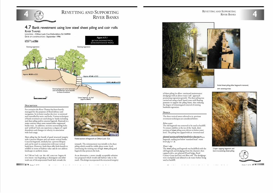
7/27/2019 MAN_mod
http://slidepdf.com/reader/full/manmod 44/84
R EVETTING AND SUPPORTING
R IVER B ANKS4
DESCRIPTION
For centuries the River Thames has been heavily managed for the purposes of flood defence andnavigation. In its lower reaches the river is restrictedand controlled by weirs and locks. Various techniquesof bank revetment are used along its banks including steel sheet piling and/or concrete bagwork. Boatwash is a major concern where more natural softer engineeredbanks exist. In addition, sections surrounding locksand ‘artificial’ lock cuts experience a degree of rapiddrawdown and changes in velocity in association
with lock usage.
Sheet piling has the benefit of good structural integrity with a proven lifespan and can retain vertical banks.Concrete bagwork, similarly, has a proven lifespanand can be used in conjunction with near verticalbank faces. However, both these offer little benefit to
wildlife in terms of habitat value and do not addresslandscape or aesthetic issues.
At C lift on l ock cut the old concr ete bagwo rk reve tment was beginning to disintegrate and allow
wash-out of the unprotected bank back towards the
towpath. The reinstatement was initially to be sheetpiling which would be visible above water level,continuing the existing run of high sheet piling andbagwork that protects the lock.
As an alternative, a more visually acceptable solution was proposed which would add habitat value to thereach. This design incorporated the structural integrity
4.7 Bank revetment using low steel sheet piling and coir rollsRIVER THAMESLOCATION - Clifton Lock Cut,Oxfordshire SU 544944
DATE OF CONSTRUCTION - September 1996
LENGTH – 140mCOST - £45,000
Towpath
0 1m Loose bagwork on bed(approx 30m3)
Approx 47.40 m.O.D.Approx 48.50 m.O.D.
SHWL 46.80 m.O.D.
Existing vegetationExisting vegetation
Typical washout profile
Existing bagwork to be removedand stockpiled for use as backfill
in areas of washout
Figure 4.7.1
SECTION SHOWINGTYPICAL
BANKANDWASHOUT PROFILE
Failed section of bagwork at Clifton Lock Cut
of sheet piling (to allow continued maintenancedredging) with an above-water ‘soft’ approachpromoting vegetation growth. The sheet piling wascarried out using a land based crane with floating pontoon to support the piling frame, thus reducing the degree of trimmingand removal of existing bankside vegetation.
DESIGN
The three vertical zones referred to in previousrevetment techniques are considered below:
Below water The old bagwork was removed to be used as backfill.To ensure stability at the toe of the bank, shortsections of sheet piling were driven to below waterlevel. The piling was capped with an inverted steel
channel section with mesh welded to the top toprevent movement of the above two courses of new bagwork, ending just below ‘standard head’ waterlevel ( fig 4.7.3).
Water’s edge The sheet piling and bagwork was backfilled with theold bagwork and dredgings from the channel, thencapped with a pre-planted (Pond Sedge, ReedCanary-Grass and Iris) coir fibre roll. The dredgings
were stockpiled and allowed to de-water before being used as backfill.
4
R EVETTING AND SUPPORTING
R IVER B ANKS
Initial sheet piling after bagwork removal,
over existing trees
2 layer capping bagwork and
tie-in to existing sheet piling
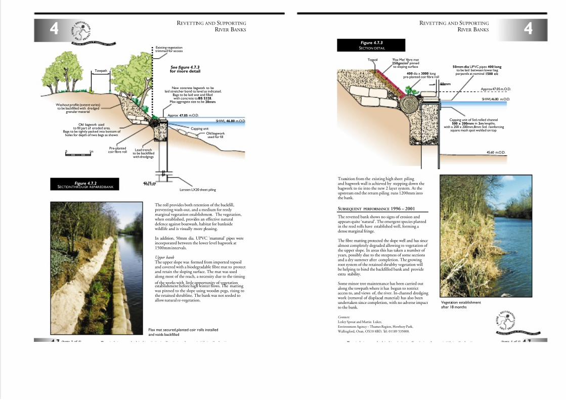
7/27/2019 MAN_mod
http://slidepdf.com/reader/full/manmod 45/84
R EVETTING AND SUPPORTING
R IVER B ANKS4
The roll provides both retention of the backfill,preventing wash-out, and a medium for reedy marginal vegetation establishment. The vegetation,
when established, provides an effective naturaldefence against boatwash, habitat for bankside
wildlife and is visually more pleasing.
In addition, 50mm dia. UPVC ‘mammal’ pipes wereincorporated between the lower level bagwork at1500mm intervals.
Upper bank The upper slope was formed from imported topsoiland covered with a biodegradable fibre mat to protectand retain the sloping surface. The mat was usedalong most of the reach, a necessity due to the timing
of the works with little opportunity of vegetationestablishment before high winter flows. The matting
was pinned to the slope using wooden pegs, rising tothe retained shrubline. The bank was not seeded toallow natural re-vegetation.
Towpath
0 1m
Capping unit
Old bagwork used for fill
New concrete bagwork to belaid stretcher bond to level as indicated.
Bags to be laid wet and filledwith concrete toBS 5328.
Max aggregate size to be 20mm
Approx 47.05 m.O.D.
42.75 mPile toe
SHWL 46.80 m.O.D.
Larssen LX20 sheet piling
Lead trenchto be backfilledwith dredgings
Pre-plantedcoir fibre roll
Existing vegetationtrimmed for access
See figure 4.7.3for more detail
Washout profile (extent varies)to be backfilled with dredged
granular material
Old bagwork usedto fill part of eroded area.
Bags to be tightly packed into bottom of holes for depth of two bags as shown
Figure 4.7.2SECTIONTHROUGH REPAIREDBANK
Flax mat secured,planted coir rolls installed
and voids backfilled
Transition from the existing high sheet piling and bagwork wall is achieved by stepping down thebagwork to tie into the new 2 layer system. At theupstream end the return piling runs 1200mm intothe bank.
SUBSEQUENT PERFORMANCE 1996 – 2001
The revetted bank shows no signs of erosion andappears quite ‘natural’. The emergent species plantedin the reed rolls have established well, forming a dense marginal fringe.
The fibre matting protected the slope well and has sincealmost completely degraded allowing re-vegetation of the upper slope. In areas this has taken a number of years, possibly due to the steepness of some sectionsand a dry summer after completion. The growing root system of the retained shrubby vegetation willbe helping to bind the backfilled bank and provideextra stability.
Some minor tree maintenance has been carried outalong the towpath where it has begun to restrictaccess to, and views of, the river. In-channel dredging
work (removal of displaced material) has also beenundertaken since completion, with no adverse impactto the bank.
Contacts:
Lesley Sproat and Martin Luker,
Environment Agency – Thames Region, Howbery Park,
Wallingford, Oxon, OX10 8BD, Tel: 01189 535000.
4
R EVETTING AND SUPPORTING
R IVER B ANKS
50mm
Capping unit of Std.rolled channel500 x 200mm in 3m lengths,
with a 200 x 200mm,8mm Std. reinforcingsquare mesh spot welded on top
50mm dia UPVC pipes 400 longto be laid between lower bagperpends at nominal 1500 c/c
Approx 47.05 m.O.D.
SHWL46.80 m.O.D.
45.60 m.O.D.
400 dia x 3000 longpre-planted coir fibre roll
'Flax Mat' fibre mat250gm/m2 pinnedto sloping surface
Topsoil
Figure 4.7.3
SECTION DETAIL
Vegetation establishmentafter 18 months
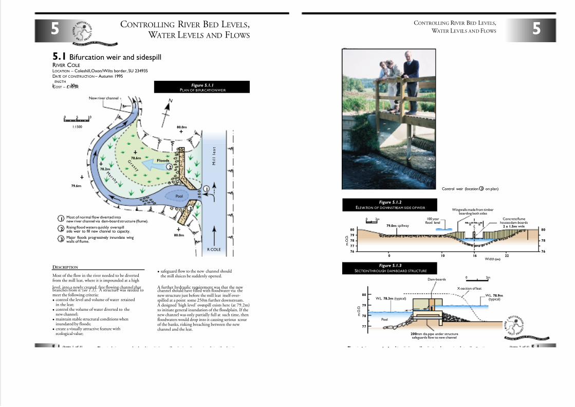
7/27/2019 MAN_mod
http://slidepdf.com/reader/full/manmod 46/84
CONTROLLING R IVER BED LEVELS, W ATER LEVELS AND FLOWS
5
5.1 Bifurcation weir and sidespillRIVER COLELOCATION – Coleshill,Oxon/Wilts border, SU 234935
DATE OF CONSTRUCTION – Autumn 1995
LENGTH
– 30mCOST – £10.5k
DESCRIPTION
Most of the flow in the river needed to be divertedfrom the mill leat, where it is impounded at a high
level, into a newly created, free flowing channel thatbranches from it (see 1.1). A structure was needed tomeet the following criteria:
• control the level and volume of water retainedin the leat;
• control the volume of water diverted to thenew channel;
• maintain stable structural conditions wheninundated by floods;
• create a visually attractive feature withecological value;
• safeguard flow to the new channel shouldthe mill sluices be suddenly opened.
A further hydraulic requirement was that the new channel should have filled with floodwater via thenew structure just before the mill leat itself over-spilled at a point some 250m further downstream.
A designed ‘high level’ overspill exists here (at 79.2m)to initiate general inundation of the floodplain. If thenew channel was only partially full at such time, thenfloodwaters would drop into it causing serious scourof the banks, risking breaching between the new channel and the leat.
80.0m
80.0m
79.6m
78.2m
78.6m
New river channel
Pool
R COLE
M i l l l e a t
FloodsG r a s s y
M a r s h y
Most of normal flow diverted intonew river channel via dam-board structure (flume).
Rising flood waters quickly overspillside weir to fill new channel to capacity.
Major floods progressively innundate wingwalls of flume.
1
1
2
3
2
3
1:1500
0 105
N
Figure 5.1.1PLAN OF BIFURCATIONWEIR
5
CONTROLLING R IVER BED LEVELS,
W ATER LEVELS AND FLOWS
DESIGN
The normal range of summer/winter base flows weirover a pair of damboards housed in a simple concreteflume. The top level at which the boards are set wascritically determined to give precise control over thedivision of low flow between the new channel (90%)
and the mill leat (10%), as well as control of the water level in the latter. A free fall of water over theboards is necessary to achieve this.
The normal water level in the new channel iscontrolled by its longitudinal bed gradient,determined independently (see 1.1), a water leveldifferential of c. 0.6m usually exists across thestructure. The new channel begins as a deep poolleading into a long sweeping bend. The pool is sus-tained by floodwaters passing through the flume.
A rock/gravel riffle was created at the downstream lipof the pool. The pool is lined with rock close to thestructure to safeguard against underscour. Beneaththe flume, a 200mm diameter pipe ensures that atleast a small flow of water continues should the levelin the leat drop below the damboards.
Control weir (location 1 on plan)
80
80
79
78
77
76
79
78
77
200mm dia.pipe under structuresafeguards flow to new channel
W.L. 78.9m(typical)
100 yearflood level
Concrete flumehouses dam-boards
2 x 1.5m wide
Wingwalls made from timberboarding both sides
W.L. 78.3m (typical)
79.0m spillway
Dam-boards
Pool
X-section of leat
80
78
76
0 10 16 22
= =
m . O . D .
m . O . D .
Width (m)
0 2m
0 2m
Figure 5.1.2
ELEVATION OF DOWNSTREAM SIDE OFWEIR
Figure 5.1.3
SECTIONTHROUGH DAM-BOARD STRUCTURE
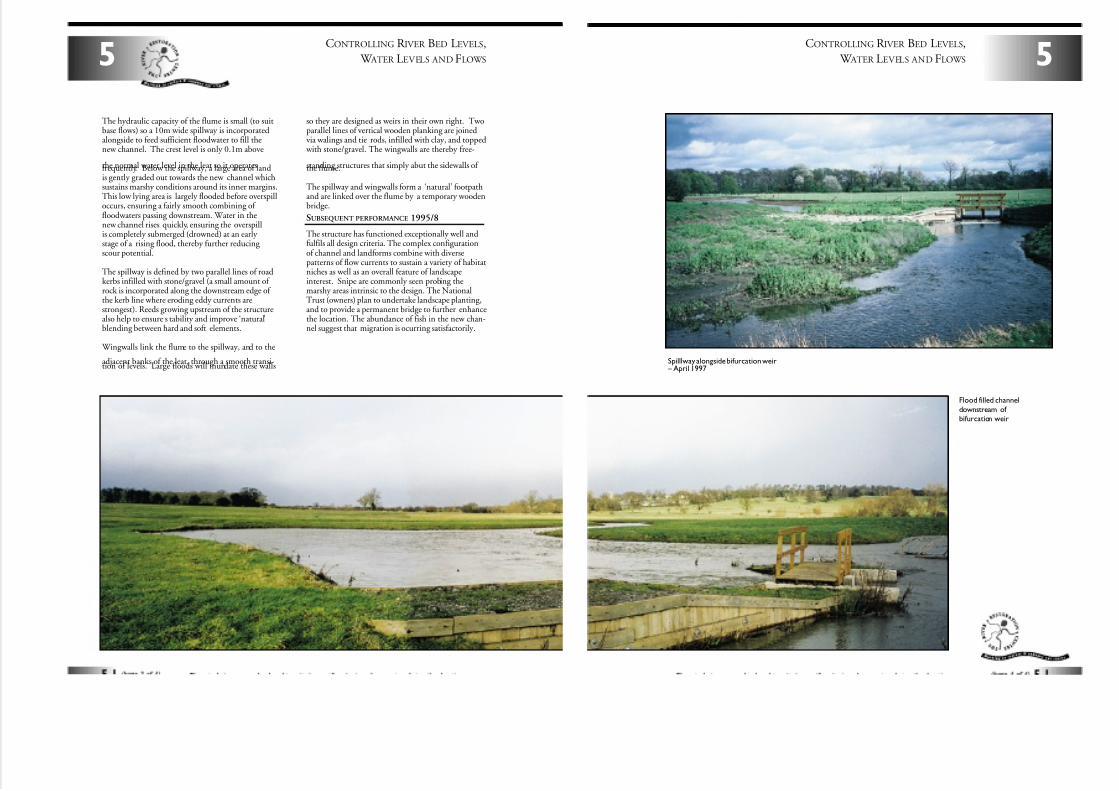
7/27/2019 MAN_mod
http://slidepdf.com/reader/full/manmod 47/84
CONTROLLING R IVER BED LEVELS,
W ATER LEVELS AND FLOWS5
The hydraulic capacity of the flume is small (to suitbase flows) so a 10m wide spillway is incorporatedalongside to feed sufficient floodwater to fill thenew channel. The crest level is only 0.1m above
the normal water level in the leat so it operatesfrequently. Below the spillway, a large area of landis gently graded out towards the new channel whichsustains marshy conditions around its inner margins.This low lying area is largely flooded before overspilloccurs, ensuring a fairly smooth combining of floodwaters passing downstream. Water in thenew channel rises quickly, ensuring the overspillis completely submerged (drowned) at an early stage of a rising flood, thereby further reducing scour potential.
The spillway is defined by two parallel lines of roadkerbs infilled with stone/gravel (a small amount of rock is incorporated along the downstream edge of the kerb line where eroding eddy currents arestrongest). Reeds growing upstream of the structurealso help to ensure s tability and improve ‘natural’blending between hard and soft elements.
Wingwalls link the flume to the spillway, and to the
adjacent banks of the leat, through a smooth transi-tion of levels. Large floods will inundate these walls
so they are designed as weirs in their own right. Twoparallel lines of vertical wooden planking are joinedvia walings and tie rods, infilled with clay, and topped
with stone/gravel. The wingwalls are thereby free-
standing structures that simply abut the sidewalls of the flume.
The spillway and wingwalls form a ‘natural’ footpathand are linked over the flume by a temporary woodenbridge.
SUBSEQUENT PERFORMANCE 1995/8
The structure has functioned exceptionally well andfulfils all design criteria. The complex configurationof channel and landforms combine with diversepatterns of flow currents to sustain a variety of habitatniches as well as an overall feature of landscapeinterest. Snipe are commonly seen probing themarshy areas intrinsic to the design. The NationalTrust (owners) plan to undertake landscape planting,and to provide a permanent bridge to further enhancethe location. The abundance of fish in the new chan-nel suggest that migration is ocurring satisfactorily.
5
CONTROLLING R IVER BED LEVELS,
W ATER LEVELS AND FLOWS
Spilllway alongside bifurcation weir – April 1997
Flood filled channel
downstream of bifurcation weir
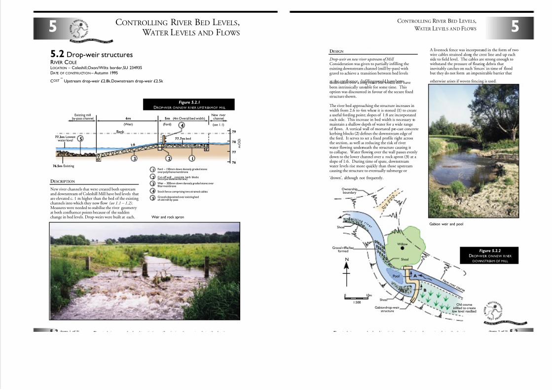
7/27/2019 MAN_mod
http://slidepdf.com/reader/full/manmod 48/84
CONTROLLING R IVER BED LEVELS, W ATER LEVELS AND FLOWS
5
DESCRIPTION
New river channels that were created both upstreamand downstream of Coleshill Mill have bed levels thatare elevated c. 1 m higher than the bed of the existing channels into which they now flow (see 1.1 – 1.2).Measures were needed to stabilise the river geometry at both confluence points because of the suddenchange in bed levels. Drop-weirs were built at each. Weir and rock apron
6m
(Weir)
5m
(Ford)
(4m Overall bed width)New riverchannel
Existing millby-pass channel
(see 1.1)
1
5
4
3 2
77.3m Lowestwater level
76.5m Existing
77.7m bed
79
78
77
76
1 :6 m . O . D .
Bank
5.2 Drop-weir structuresRIVER COLELOCATION – Coleshill,Oxon/Wilts border,SU 234935
DATE OF CONSTRUCTION – Autumn 1995
COST–
Upstream drop-weir £2.8k.Downstream drop-weir £2.5k
Figure 5.2.1
DROP-WEIR ONNEW RIVER UPSTREAMOF MILL
5
3
4
1
2
Ford – 150mm down densely graded stoneover polythene membrane
Cut-off wall –
concrete kerb blocks(incorporates membrane)
Weir – 300mm down densely graded stone overfilter membrane
Stock fence comprising two strained cables
Gravels deposited over existing bedof old mill by-pass
0 10m
1:500
N
Pool A
B
Gabion drop-weirstructure
Shoal
Shoal
Shoal
Ownershipboundary
Gravel riffle/barformed
E x i s t i n g r i v
e r
Willow
N e w r i v e r c o u r s e
Old courseinfilled to create
low level reedbed
D r
y d i t
c h
5
CONTROLLING R IVER BED LEVELS,
W ATER LEVELS AND FLOWS
DESIGN
Drop-weir on new river upstream of Mill Consideration was given to partially infilling theexisting downstream channel (mill by-pass) withgravel to achieve a transition between bed levels
at the confluence. Infilling would have beenundertaken over a long reach but would still havebeen intrinsically unstable for some time. Thisoption was discounted in favour of the secure fixedstructure shown.
The river bed approaching the structure increases in width from 2.6 to 4m where it is stoned (1) to createa useful fording point; slopes of 1:8 are incorporatedeach side. This increase in bed width is necessary tomaintain a shallow depth of water for a wide rangeof flows. A vertical wall of mortared pre-cast concretekerbing blocks (2) defines the downstream edge of the ford. It serves to set a fixed profile right acrossthe section, as well as reducing the risk of river
water flowing underneath the structure causing itto collapse. Water flowing over the wall passes evenly down to the lower channel over a rock apron (3) at a slope of 1:6. During time of spate, downstream
water levels rise more quickly than those upstreamcausing the structure to eventually submerge or
‘drown’, although not frequently.
Figure 5.2.2
DROP-WEIR ONNEW RIVER
DOWNSTREAM OF MILL
Gabion weir and pool
A livestock fence was incorporated in the form of two wire cables strained along the crest line and up eachside to field level. The cables are strong enough to
withstand the pressure of floating debris thatinevitably catches on such ‘fences’ in time of floodbut they do not form an impenitrable barrier that
otherwise arises if woven fencing is used.
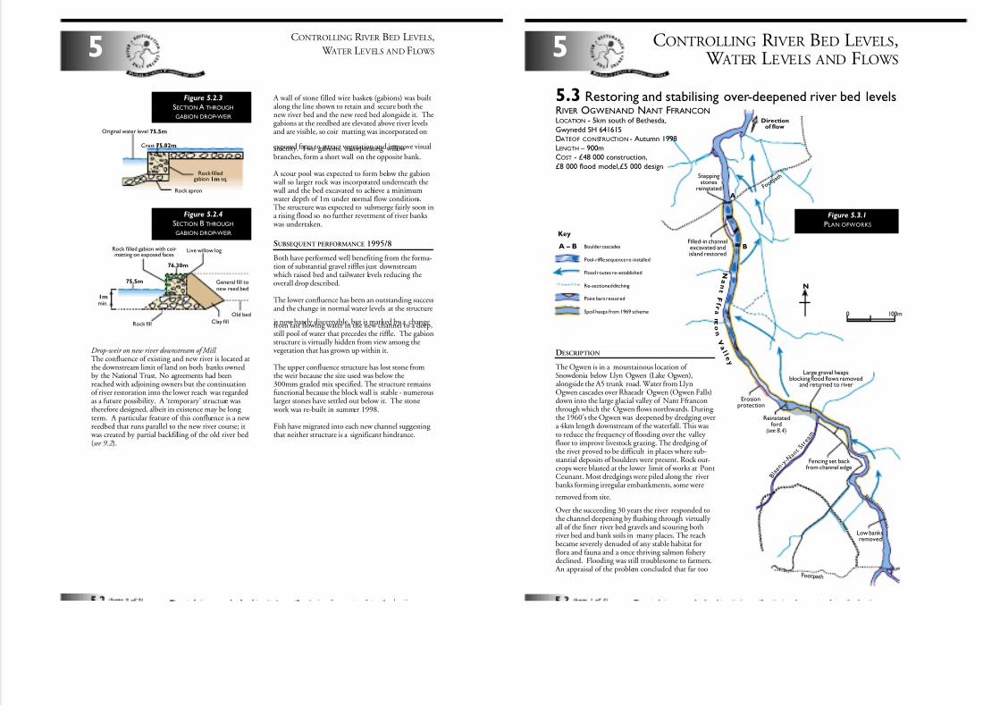
7/27/2019 MAN_mod
http://slidepdf.com/reader/full/manmod 49/84
A wall of stone filled wire baskets (gabions) was builtalong the line shown to retain and secure both thenew river bed and the new reed bed alongside it. Thegabions at the reedbed are elevated above river levelsand are visible, so coir matting was incorporated on
exposed faces to attract vegetation and improve visualamenity. Two gabions, incorporating willow branches, form a short wall on the opposite bank.
A scour pool was expected to form below the gabion wall so larger rock was incorporated underneath the wall and the bed excavated to achieve a minimum water depth of 1m under normal flow conditions.The structure was expected to submerge fairly soon ina rising flood so no further revetment of river banks
was undertaken.
SUBSEQUENT PERFORMANCE 1995/8
Both have performed well benefiting from the forma-tion of substantial gravel riffles just downstream
which raised bed and tailwater levels reducing theoverall drop described.
The lower confluence has been an outstanding successand the change in normal water levels at the structure
is now barely discernable, but is marked by a changefrom fast flowing water in the new channel to a deep,still pool of water that precedes the riffle. The gabionstructure is virtually hidden from view among thevegetation that has grown up within it.
The upper confluence structure has lost stone fromthe weir because the size used was below the300mm graded mix specified. The structure remainsfunctional because the block wall is stable - numerouslarger stones have settled out below it. The stone
work was re-built in summer 1998.
Fish have migrated into each new channel suggesting that neither structure is a significant hindrance.
CONTROLLING R IVER BED LEVELS,
W ATER LEVELS AND FLOWS5
Original water level 75.5m
Crest 75.82m
Rock filledgabion 1m sq.
Rock apron
Figure 5.2.3
SECTION A THROUGH
GABION DROP-WEIR
75.5m
Rock fill
1mmin.
Rock filled gabion with coirmatting on exposed faces
Live willow log
Clay fill
General fill tonew reed bed
Old bed
76.30m
Figure 5.2.4
SECTION B THROUGH
GABION DROP-WEIR
Drop-weir on new river downstream of Mill The confluence of existing and new river is located atthe downstream limit of land on both banks ownedby the National Trust. No agreements had beenreached with adjoining owners but the continuationof river restoration into the lower reach was regardedas a future possibility. A ‘temporary’ structure wastherefore designed, albeit its existence may be long term. A particular feature of this confluence is a new reedbed that runs parallel to the new river course; it
was created by partial backfilling of the old river bed(see 9.2 ).
CONTROLLING R IVER BED LEVELS, W ATER LEVELS AND FLOWS
5
N
Erosionprotection
Directionof flow
Filled-in channelexcavated andisland restored
Steppingstones
reinstated
Reinstatedford
(see 8.4)
Fencing set back from channel edge
Low banksremoved
Large gravel heapsblocking flood flows removed
and returned to river
A
B
N a n t
F f r a
n c
o
n
V a l l e y
F o o t
p a t h
F oot pat h
B l a
e n
- y - N a n
tS t r
e a m
0 100m
5.3 Restoring and stabilising over-deepened river bed levelsRIVER OGWENAND NANT FFRANCONLOCATION - 5km south of Bethesda,
Gwynedd SH 641615DATEOF CONSTRUCTION - Autumn 1998
LENGTH – 900mCOST - £48 000 construction,
£8 000 flood model,£5 000 design
A – B
Key
Boulder cascades
Pool-riffle sequence re-installed
Flood routes re-established
Re-sectioned ditching
Point bars restored
Spoil heaps from 1969 scheme
Figure 5.3.1
PLAN OFWORKS
DESCRIPTION
The Ogwen is in a mountainous location of Snowdonia below Llyn Ogwen (Lake Ogwen),alongside the A5 trunk road. Water from LlynOgwen cascades over Rhaeadr Ogwen (Ogwen Falls)down into the large glacial valley of Nant Ffranconthrough which the Ogwen flows northwards. During the 1960’s the Ogwen was deepened by dredging overa 4km length downstream of the waterfall. This wasto reduce the frequency of flooding over the valley floor to improve livestock grazing. The dredging of the river proved to be difficult in places where sub-stantial deposits of boulders were present. Rock out-crops were blasted at the lower limit of works at PontCeunant. Most dredgings were piled along the riverbanks forming irregular embankments, some were
removed from site.
Over the succeeding 30 years the river responded tothe channel deepening by flushing through virtually all of the finer river bed gravels and scouring bothriver bed and bank soils in many places. The reachbecame severely denuded of any stable habitat forflora and fauna and a once thriving salmon fishery declined. Flooding was still troublesome to farmers.
An appraisal of the problem concluded that far too
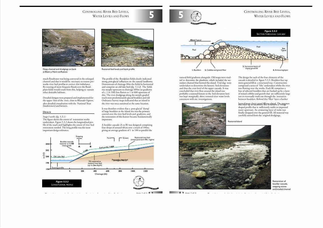
7/27/2019 MAN_mod
http://slidepdf.com/reader/full/manmod 50/84
5
CONTROLLING R IVER BED LEVELS,
W ATER LEVELS AND FLOWS
much floodwater was being conveyed in the enlargedchannel and that it would be necessary to restore pre-
works river bed profiles to correct this imbalance.Re-routing of more frequent floods over the flood-plain fields would result from this, helping to sustainother desirable habitats.
Detailed designs were prepared and implemented forthe upper 1km of the river, close to Rhaeadr Ogwen,after detailed consultation with the National Trust(landowners) and farmers.
DESIGN
Stage I works (fig. 5.3.1)The figure shows the extent of restoration worksundertaken. Figure 5.3.2 shows the longitudinal pro-file of the reach and highlights the extent of river bedrestoration needed. The long profile was the mostimportant design reference.
The profile of the floodplain fields clearly indicatedstrong post-glacial influences on the natural landforms.Downstream of chainage 00m the fields lie horizontaland comprise an old lake bed ( fig. 5.3.2 ). The fieldsrise steeply upstream to chainage 400m (at gradientsof c. 1 in 100) but flatten to 1 in 600 upstream of this. The river dredgings along the steeply gradedreach were predominantly glacial boulders and oldOrdnance Survey maps indicated that an island inthe river was once sustained at the same location.
It was therefore evident that a post-glacial ‘dump’of large boulders at the island site was the primary control over the river bed levels and gradients, andthe restoration of this feature became fundamentally important.
A boulder cascade (A to B) was designed comprising four drops of around 40cm over a reach of 100m,giving an average gradient of 1 in 100 to parallel the
m . O . D .
0 200
A B
400 600 800 1000 1200
Chainage (m)
196
198
200
202
204
006:1eli forpdleiF
StreamFordSteppingstones
Fill required torestore river bed(up to 2m depth)
Pre-works river bed(dredged 1960's)
Restored river bed(mean) pool and riffle regime
Boulder cascaderestored at 1:100
mean grade
Old Lake Bed
Existing profile
1 : 1 0 0
Figure 5.3.2
LONGITUDINAL PROFILE
Deep channel and dredgings on bank at Blaen-y-Nant confluence
Restored bed levels and bank profile
CONTROLLING R IVER BED LEVELS,
W ATER LEVELS AND FLOWS5
natural field gradients alongside. Old maps were stud-ied to determine the planform, which included the sec-ondary channel that formed the island. Trial digs wereundertaken to determine the historic bed elevationsand thus the crest level of the upper cascade. It wasconcluded that river flow around the island wasprobably a seasonal feature so the bed elevation here
was kept marginally above restored river water levelsconsistent with site investigations.
The design for each of the four elements of thecascade is detailed in figure 5.3.3. Boulders face-upmore general fill in a structured way. Constructioncomprised a series of ‘lifts’ undertaken whilst the river
was flowing over the works. Each lift comprises a line of selected boulders that are backed up by a layerof mixed cobbles and gravels that are sufficiently largenot to eventually wash out through the intersticesbetween boulders. Behind this ‘filter’ layer a further
layer of more clayey gravel fill was placed. The structure was built up in successive lifts to achieve a ‘wedge’shaped profile that is sufficiently stable to impound
water upstream. An armouring layer of rocks wasfinally dropped over the general fill. All material wascarefully sorted from the original dredgings.
Pool
Pool
40cmTypical
2m
Typical
3. Successive layers of clayey gravel fill
4.Armouring layer2.Cobbles and gravel filter1.Boulders
Figure 5.3.3
SECTION THROUGHA CASCADE
Restoration of boulder cascade,stepping stones
and braided channel
Restored island
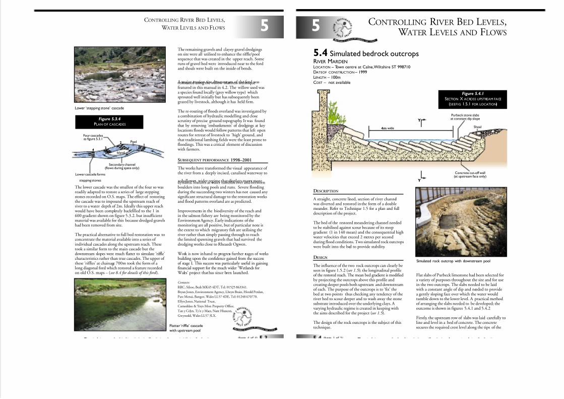
7/27/2019 MAN_mod
http://slidepdf.com/reader/full/manmod 51/84
The lower cascade was the smallest of the four so wasreadily adapted to restore a series of large stepping stones recorded on O.S. maps. The effect of restoring the cascade was to impound the upstream reach of river to a water depth of 2m. Ideally this upper reach
would have been completely backfilled to the 1 in600 gradient shown on figure 5.3.2. but insufficientmaterial was available for this because dredged gravelshad been removed from site.
The practical alternative to full bed restoration was toconcentrate the material available into a series of individual cascades along the upstream reach. Thesetook a similar form to the main cascade but thedownstream slopes were much flatter to simulate ‘riffle’characteristics rather than true cascades. The upper of these ‘riffles’ at chainage 700m took the form of a long diagonal ford which restored a feature recordedon old O.S. maps – (see 8.4 for details of this ford ).
The remaining gravels and clayey gravel dredgingson site were all utilised to enhance the riffle/poolsequence that was created in the upper reach. Someruns of gravel bed were introduced near to the fordand shoals were built on the inside of bends.
A major erosion site downstream of the ford wasreinstated using the willow mattress techniquefeatured in this manual in 4.2. The willow used wasa species found locally (grey willow type) whichsprouted well initially but has subsequently beengrazed by livestock, although it has held firm.
The re-routing of floods overland was investigated by a combination of hydraulic modelling and closescrutiny of precise ground topography. It was foundthat by removing ‘embankments’ of dredgings at key locations floods would follow patterns that left openroutes for retreat of livestock to ‘high’ ground, andthat traditional lambing fields were the least prone tofloodings. This was a critical element of discussion
with farmers.
SUBSEQUENT PERFORMANCE 1998–2001
The works have transformed the visual appearance of the river from a deeply incised, canalised waterway to
a shallower, wider regime that displays many moredynamic features as water tumbles over and betweenboulders into long pools and runs. Severe flooding during the succeeding two winters has not caused any significant structural damage to the restoration worksand flood patterns overland are as predicted.
Improvements in the biodiversity of the reach andin the salmon fishery are being monitored by theEnvironment Agency. Early indications of themonitoring are all positive, but of particular note isthe extent to which migratory fish are utilising theriver rather than simply passing through to reachthe limited spawning gravels that had survived thedredging works close to Rheaedr Ogwen.
Work is now in hand to progress further stages of worksbuilding upon the confidence gained from the successof stage I. This success was particularly useful in gaining financial support for the much wider ‘Wetlands for
Wales’ project that has since been launched.
Contacts:
RRC, Silsoe, Beds MK45 4DT, Tel: 01525 863341.
Bryan Jones, Environment Agency, Llwyn Brain, Ffordd Penlan,
Parc Menai, Bangor, Wales LL57 4DE, Tel: 01248 670770.
Elfyn Jones. National Trust,
Carneddau & Ynys Mon Property Office,
Tan y Celyn, Ty’n y Maes, Nant Ffrancon,
Gwynedd, Wales LL57 3LX.
5
CONTROLLING R IVER BED LEVELS,
W ATER LEVELS AND FLOWS
Pool
Secondary channel(flows during spate only)
Lower cascade forms
stepping stones
Four cascadesas figure 5.3.1
12
34
Island
Figure 5.3.4
PLAN OF CASCADES
Lower ‘stepping stone’ cascade
Flatter ‘riffle’ cascade
with upstream pool
DESCRIPTION
A straight, concrete lined, section of river channel was diverted and restored in the form of a doublemeander. Refer to Technique 1.5 for a plan and fulldescription of the project.
The bed of the restored meandering channel neededto be stabilised against scour because of its steepgradient (1 in 140 mean) and the consequential high
water velocities that exceed 2 metres per secondduring flood conditions. Two simulated rock outcrops
were built into the bed to provide stability.
DESIGN
The influence of the two rock outcrops can clearly beseen in figure 1.5.2 (see 1.5 ); the longitudinal profileof the restored reach. The mean bed gradient is modifiedby projecting the outcrops above this profile andcreating deeper pools both upstream and downstreamof each. The purpose of the outcrops is to ‘fix’ thebed at two points thus checking any tendency of theriver bed to scour deeper and to wash away the stonesubstrate introduced over the underlying clays. A varying hydraulic regime is created in keeping withthe aims described for the project (see 1.5 ).
The design of the rock outcrops is the subject of thistechnique.
Flat slabs of Purbeck limestone had been selected fora variety of purposes throughout the site and for usein the two outcrops. The slabs needed to be laid
with a constant angle of dip and needed to providea gently sloping face over which the water wouldtumble down to the lower level. A practical methodof arranging the slabs needed to be developed; theoutcome is shown in figures 5.4.1 and 5.4.2
Firstly, the upstream row of slabs was laid carefully toline and level in a bed of concrete. The concretesecures the required crest level along the tips of the
CONTROLLING R IVER BED LEVELS, W ATER LEVELS AND FLOWS
5
5.4 Simulated bedrock outcropsRIVER MARDENLOCATION – Town centre at Calne,Wiltshire ST 998710
DATEOF CONSTRUCTION – 1999
LENGTH – 100m
COST – not available
Y
Y
4m wide
Concrete cut-off wall(at upstream face only)
Purbeck stone slabsat constant dip slope
Shoal
Figure 5.4.1
SECTION X ACROSS UPSTREAM FACE
(SEEFIG 1.5.1 FOR LOCATION)
Simulated rock outcrop with downstream pool
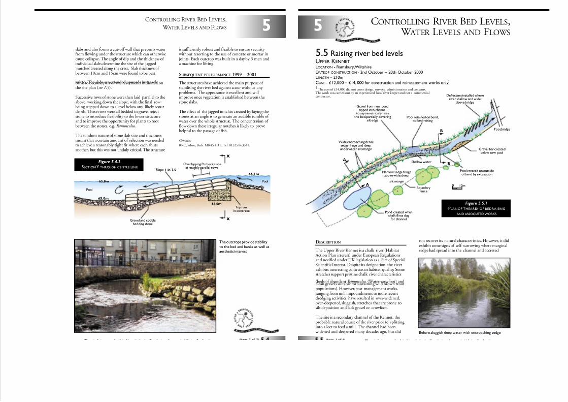
7/27/2019 MAN_mod
http://slidepdf.com/reader/full/manmod 52/84
slabs and also forms a cut-off wall that prevents waterfrom flowing under the structure which can otherwisecause collapse. The angle of dip and the thickness of individual slabs determine the size of the jagged‘notches’ created along the crest. Slab thickness of between 10cm and 15cm were found to be best
suited. The slabs are extended upwards into eachbank to become part of the revetments indicated onthe site plan (see 1.5 ).
Successive rows of stone were then laid parallel to theabove, working down the slope, with the final row being stepped down to a level below any likely scourdepth. These rows were all bedded in gravel rejectstone to introduce flexibility to the lower structureand to improve the opportunity for plants to rootbetween the stones, e.g. Ranunculus .
The random nature of stone slab s ize and thicknessmeant that a certain amount of selection was neededto achieve a reasonably tight fit where each abutsanother, but this was not unduly critical. The structure
is sufficiently robust and flexible to ensure s ecurity without resorting to the use of concrete or mortar in joints. Each outcrop was built in a day by 3 men anda machine for lifting.
SUBSEQUENT PERFORMANCE 1999 – 2001
The structures have achieved the main purpose of stabilising the river bed against scour without any problems. The appearance is excellent and willimprove once vegetation is established between thestone slabs.
The effect of the jagged notches created by laying thestones at an angle is to generate an audible tumble of
water over the whole structure. The concentration of flow down these irregular notches is likely to provehelpful to the passage of fish.
Contacts:
RRC, Silsoe, Beds. MK45 4DT, Tel: 01525 863341.
5
CONTROLLING R IVER BED LEVELS,
W ATER LEVELS AND FLOWS
X
X
Pool
Pool
65.0m
66.1m
65.8m
65.0m
Top rowin concrete
Gravel and cobblebedding stone
Slope 1 in 7.5
Overlapping Purbeck slabsin roughly parallel rows
Figure 5.4.2
SECTION Y THROUGH CENTRE LINE
The outcrops provide stability
to the bed and banks as well asaesthetic interest
CONTROLLING R IVER BED LEVELS, W ATER LEVELS AND FLOWS
5
DESCRIPTION
The Upper River Kennet is a chalk river (Habitat Action Plan interest) under European Regulationsand notified under UK legislation as a Site of SpecialScientific Interest. Despite its designation, the riverexhibits interesting contrasts in habitat quality. Somestretches support pristine chalk river characteristics
(beds of abundant Ranunculus (Water-crowfoot) andclean gravels suitable for sustaining wild brown troutpopulations). However, past management works,ranging from mill impoundments to more recentdredging activities, have resulted in over-widened,over-deepened, sluggish, stretches that are prone tosilt deposition and lack gravel or crowfoot.
The site is a secondary channel of the Kennet, theprobable natural course of the river prior to splitting into a leet to feed a mill. The channel had been
widened and deepened many decades ago, but did
not recover its natural characteristics. However, it didexhibit some signs of self-narrowing where marginalsedge had spread into the channel and accreted
5.5 Raising river bed levelsUPPER KENNETLOCATION - Ramsbury,Wiltshire
DATEOF CONSTRUCTION - 2nd October – 20th October 2000LENGTH – 210m
COST - £12,000 – £14, 000 for construction and reinstatement works only†
A
A
B
B
Pool created on outsideof bend by excavation
Gravel bar createdbelow new pool
Shallow water
Narrow sedge fringeabove wide,deep,
silt margin
Boundaryfence
Pond created whenchalk flints dug
for channel
Pool retained on bend,no bed raising
Deflectors installed whereriver shallow and wide
above bridge
Wide encroaching densesedge fringe and deepunderwater silt margin
Gravel from new pondtipped into channel
to asymmetrically raisethe bed,partially covering
silt edge
Footbridge
0 10m
Figure 5.5.1
PLANOF THEAREA OF BEDRAISING
AND ASSOCIATED WORKS
†The cost of £14,000 did not cover design, surveys, administration and consents.
The work was carried out by an experienced local river keeper and not a commercialcontractor.
Before:sluggish deep water with encroaching sedge

7/27/2019 MAN_mod
http://slidepdf.com/reader/full/manmod 53/84
significant silt shoulders. Despite this development,the channel remained too wide to sustain fast watercurrents and even in mid-channel the bed was subjectto deep silt accretion.
A common approach to achieving self-s ustaining
habitats in enlarged degraded rivers is to narrow the river bed width and thereby concentrate flows within a defined low-flow channel. However, wherethe river also has a history of deepening, this may simply lead to the formation of a very constricted,deep course. To restore a more appropriate width todepth ratio, bed raising may also need to beconsidered (see 1.2 for further discussion on selecting the appropriate cross section).
A 210m stretch upstream of Ramsbury wasre-configured, primarily through raising the bed. Thechannel bed was raised asymmetrically to ensure thatthere was a narrow low-flow course and shallow edgesto encourage marginal vegetation encroachment.
As the Kennet is a chalk stream the predominant flow is derived from groundwater, so major fluctuations in
water level and velocity are much less than in riversfed primarily by surface water. Consequently, a moreflexible approach can be adopted for the location of
gravel materials to raise the bed, as there is less risk of subsequent mass re-distribution.
Detailed flow modelling was a key element todetermine the effects of the works under low-flow and flood conditions, for land drainage consent andto allay potential landowner concerns.
DESIGN
Throughout, bed levels were raised to leave a maximum water depth of 500mm at low water level (based on
the Q90 discharge level - the level at which flowsare exceeded 90% of the time). At this discharge,the margins of the channel would have a depth of <100mm. The Q90 flow was indicative; the desire
was to ensure that under very low flows the bed-width would be constricted to sustain at least some clean
gravel at all times. The maximum depth of 500mm atQ90 was based on a target reference width and depth.
Work was scheduled to commence in early October when river flows are usually at an annual low,approximating to Q90. Prior to undertaking work,stakes were placed in the river to mark this level as a guide to the contractor during the gravel placementprocess. This was especially important since waterlevels would change if silt entrapment measures hadneeded to be installed downstream (on standby butnot needed).
5
CONTROLLING RIVER BED LEVELS, WATER LEVELS AND FLOWS
Approx 2 to 4m
SiltBed raised
to leave 500mmto the Q90 level
Water level (109.43mm moD)(Q90 flow)
High water flow (109.78mm moD)
Silt
Existing sedge
Existing sedge
Excavated material fromadjacent pond tipped on bed
to low flow water levels gradedto form asymmetric channel cross-section
Figure 5.5.2
SECTION A THROUGH RAISED BED
AND MARGINALSHOAL
Gravel placement may influence or be influenced by
fluctuating water levels
CONTROLLING R IVER BED LEVELS,
W ATER LEVELS AND FLOWS5
The material used to shallow the channel depth waschalky and gravel flints. Where possible it is advisableto use material from the immediate area to reflectthe type of bed that would have been present undernatural conditions. Here the gravel fill was excavatedfrom the floodplain by the creation of an adjacent
pond on the right bank. The suitability of thematerial was checked beforehand by the inspectionof machine-excavated trial pits. Infill material waspredominantly a mixture of gravels and flints varying in size from 20 to 10mm, with <5% coarse sand andminimal silt. A few larger flints were also present.
Topsoil and overburden were first stripped andstored before the gravel was dug out and transportedby dumpers to the river bank. Representative crosssections were produced as references for theplacement of material so that a degree of sinuosity
was created under low flow.
The contractor followed the drawings and had theadvantages of both knowing the river stretch well andhaving been involved in the final design. Regularon-site supervision was provided by an experiencedteam member.
The works length can be divided into three sections.
A. Straight with marginal sedge on both sides Cross section A ( fig. 5.5.2 ) is a typical sectionacross this reach. Silt colonised by sedge repre-sents up to half of the total channel width.
Gravel has been used to shallow and narrow theremaining open water channel by up to a half,
with the shallower margins finishing just below the Q90 level. The remaining low-flow channelis raised to within 500mm of the Q90 surface.
B. ‘S’ bend with some marginal sedge The outsides of each bend are enhanced with a pool, the first by retaining existing very deep
Approx 4.75m Approx 3.4m
Silt retainedwith sedges
Excavated materialfrom adjacent pond
graded to formasymmetric channel cross-section
Water level (109.42mm moD)(Q90 flow)
High water flow (109.73mm moD)
Water level (109.42mm AoD)(Q90 flow)
Hard bed removedto form deep pool
Existing sedge Existing sedge and silttranslocated to adjacent pond
Figure 5.5.3
SECTION B THROUGH RAISED BED
AND NEWPOOL
Flinty gravel used to narrow and raise the river bed
New pond with early growth,showing the gravellynature of the floodplain material
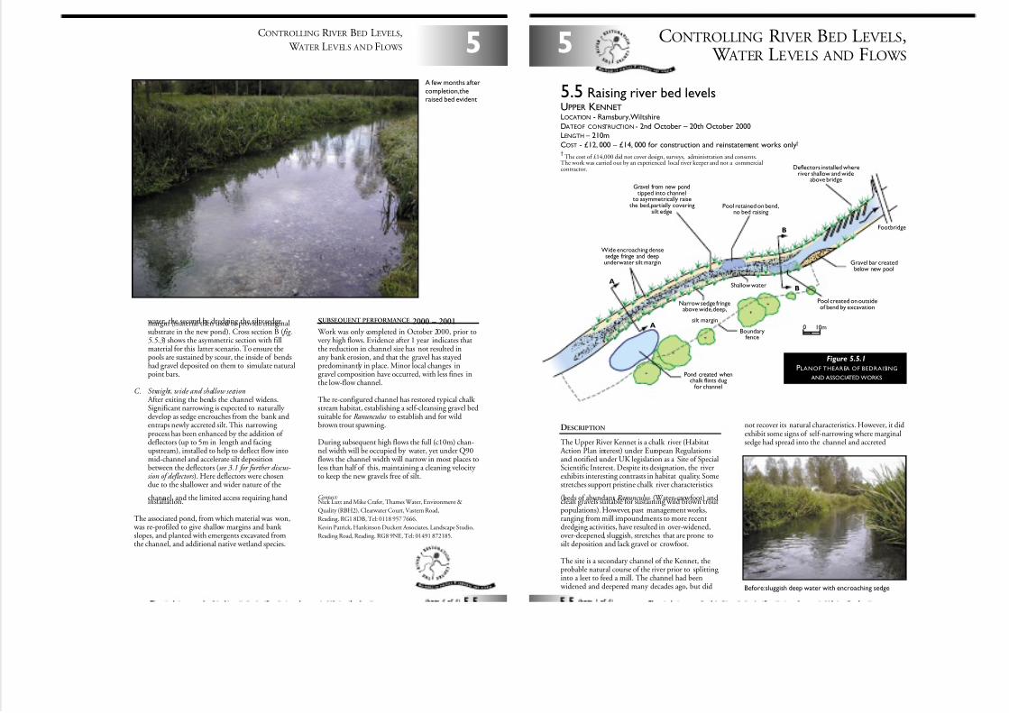
7/27/2019 MAN_mod
http://slidepdf.com/reader/full/manmod 54/84
water, the second by dredging the silty sedgemargin (material then used to provide marginalsubstrate in the new pond). Cross section B ( fig.5.5.3) shows the asymmetric section with fillmaterial for this latter scenario. To ensure thepools are sustained by scour, the inside of bendshad gravel deposited on them to simulate naturalpoint bars.
C. Straight, wide and shallow section After exiting the bends the channel widens.Significant narrowing is expected to naturally develop as sedge encroaches from the bank andentraps newly accreted silt. This narrowing process has been enhanced by the addition of deflectors (up to 5m in length and facing upstream), installed to help to deflect flow intomid-channel and accelerate silt depositionbetween the deflectors (see 3.1 for further discus-sion of deflectors ). Here deflectors were chosendue to the shallower and wider nature of the
channel, and the limited access requiring handinstallation.
The associated pond, from which material was won, was re-profiled to give shallow margins and bank slopes, and planted with emergents excavated fromthe channel, and additional native wetland species.
SUBSEQUENT PERFORMANCE 2000 – 2001
Work was only completed in October 2000, prior tovery high flows. Evidence after 1 year indicates thatthe reduction in channel size has not resulted inany bank erosion, and that the gravel has stayedpredominantly in place. Minor local changes ingravel composition have occurred, with less fines inthe low-flow channel.
The re-configured channel has restored typical chalk stream habitat, establishing a self-cleansing gravel bedsuitable for Ranunculus to establish and for wildbrown trout spawning.
During subsequent high flows the full (c10m) chan-nel width will be occupied by water, yet under Q90flows the channel width will narrow in most places toless than half of this, maintaining a cleaning velocity to keep the new gravels free of silt.
Contact:Nick Lutt and Mike Crafer, Thames Water, Environment &
Quality (RBH2), Clearwater Court, Vastern Road,
Reading. RG1 8DB, Tel: 0118 957 7666.
Kevin Patrick, Hankinson Duckett Associates, Landscape Studio,
Reading Road, Reading. RG8 9NE, Tel: 01491 872185.
5
CONTROLLING R IVER BED LEVELS,
W ATER LEVELS AND FLOWS
A few months after
completion,theraised bed evident
CONTROLLING R IVER BED LEVELS, W ATER LEVELS AND FLOWS
5
DESCRIPTION
The Upper River Kennet is a chalk river (Habitat Action Plan interest) under European Regulationsand notified under UK legislation as a Site of SpecialScientific Interest. Despite its designation, the riverexhibits interesting contrasts in habitat quality. Somestretches support pristine chalk river characteristics
(beds of abundant Ranunculus (Water-crowfoot) andclean gravels suitable for sustaining wild brown troutpopulations). However, past management works,ranging from mill impoundments to more recentdredging activities, have resulted in over-widened,over-deepened, sluggish, stretches that are prone tosilt deposition and lack gravel or crowfoot.
The site is a secondary channel of the Kennet, theprobable natural course of the river prior to splitting into a leet to feed a mill. The channel had been
widened and deepened many decades ago, but did
not recover its natural characteristics. However, it didexhibit some signs of self-narrowing where marginalsedge had spread into the channel and accreted
5.5 Raising river bed levelsUPPER KENNETLOCATION - Ramsbury,Wiltshire
DATEOF CONSTRUCTION - 2nd October – 20th October 2000LENGTH – 210m
COST - £12, 000 – £14, 000 for construction and reinstatement works only†
A
A
B
B
Pool created on outsideof bend by excavation
Gravel bar createdbelow new pool
Shallow water
Narrow sedge fringeabove wide,deep,
silt margin
Boundaryfence
Pond created whenchalk flints dug
for channel
Pool retained on bend,no bed raising
Deflectors installed whereriver shallow and wide
above bridge
Wide encroaching densesedge fringe and deepunderwater silt margin
Gravel from new pondtipped into channel
to asymmetrically raisethe bed,partially covering
silt edge
Footbridge
0 10m
Figure 5.5.1
PLANOF THEAREA OF BEDRAISING
AND ASSOCIATED WORKS
†The cost of £14,000 did not cover design, surveys, administration and consents.
The work was carried out by an experienced local river keeper and not a commercialcontractor.
Before:sluggish deep water with encroaching sedge
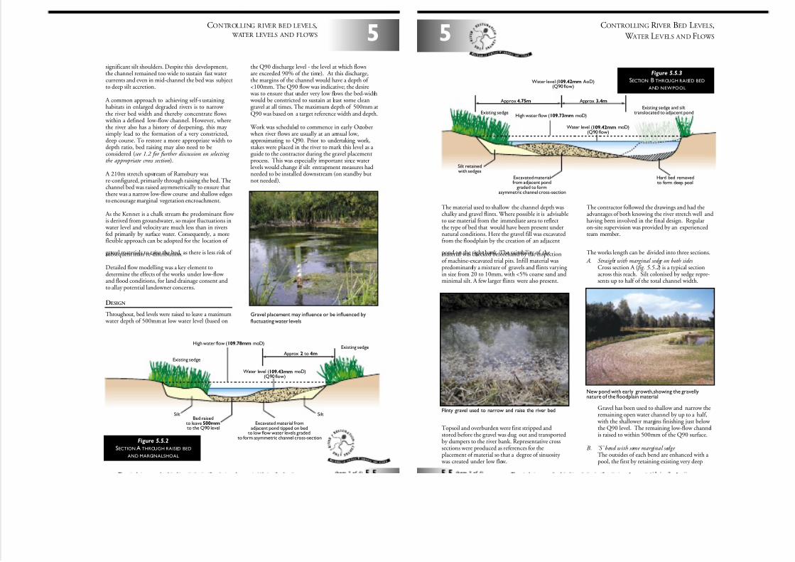
7/27/2019 MAN_mod
http://slidepdf.com/reader/full/manmod 55/84
significant silt shoulders. Despite this development,the channel remained too wide to sustain fast watercurrents and even in mid-channel the bed was subjectto deep silt accretion.
A common approach to achieving self-s ustaining habitats in enlarged degraded rivers is to narrow the river bed width and thereby concentrate flows
within a defined low-flow channel. However, wherethe river also has a history of deepening, this may simply lead to the formation of a very constricted,deep course. To restore a more appropriate width todepth ratio, bed raising may also need to beconsidered (see 1.2 for further discussion on selecting the appropriate cross section).
A 210m stretch upstream of Ramsbury wasre-configured, primarily through raising the bed. Thechannel bed was raised asymmetrically to ensure thatthere was a narrow low-flow course and shallow edgesto encourage marginal vegetation encroachment.
As the Kennet is a chalk stream the predominant flow is derived from groundwater, so major fluctuations in
water level and velocity are much less than in riversfed primarily by surface water. Consequently, a moreflexible approach can be adopted for the location of
gravel materials to raise the bed, as there is less risk of subsequent mass re-distribution.
Detailed flow modelling was a key element todetermine the effects of the works under low-flow and flood conditions, for land drainage consent andto allay potential landowner concerns.
DESIGN
Throughout, bed levels were raised to leave a maximum water depth of 500mm at low water level (based on
the Q90 discharge level - the level at which flowsare exceeded 90% of the time). At this discharge,the margins of the channel would have a depth of <100mm. The Q90 flow was indicative; the desire
was to ensure that under very low flows the bed-width would be constricted to sustain at least some cleangravel at all times. The maximum depth of 500mm atQ90 was based on a target reference width and depth.
Work was scheduled to commence in early October when river flows are usually at an annual low,approximating to Q90. Prior to undertaking work,stakes were placed in the river to mark this level as a guide to the contractor during the gravel placementprocess. This was especially important since waterlevels would change if silt entrapment measures hadneeded to be installed downstream (on standby butnot needed).
5
CONTROLLING RIVER BED LEVELS, WATER LEVELS AND FLOWS
Approx 2 to 4m
SiltBed raised
to leave 500mm
to the Q90 level
Water level (109.43mm moD)(Q90 flow)
High water flow (109.78mm moD)
Silt
Existing sedge
Existing sedge
Excavated material fromadjacent pond tipped on bed
to low flow water levels gradedto form asymmetric channel cross-section
Figure 5.5.2
SECTION A THROUGH RAISED BED
AND MARGINALSHOAL
Gravel placement may influence or be influenced by
fluctuating water levels
CONTROLLING R IVER BED LEVELS,
W ATER LEVELS AND FLOWS5
The material used to shallow the channel depth waschalky and gravel flints. Where possible it is advisableto use material from the immediate area to reflectthe type of bed that would have been present undernatural conditions. Here the gravel fill was excavatedfrom the floodplain by the creation of an adjacent
pond on the right bank. The suitability of thematerial was checked beforehand by the inspectionof machine-excavated trial pits. Infill material waspredominantly a mixture of gravels and flints varying in size from 20 to 10mm, with <5% coarse sand andminimal silt. A few larger flints were also present.
Topsoil and overburden were first stripped andstored before the gravel was dug out and transportedby dumpers to the river bank. Representative crosssections were produced as references for theplacement of material so that a degree of sinuosity
was created under low flow.
The contractor followed the drawings and had theadvantages of both knowing the river stretch well andhaving been involved in the final design. Regularon-site supervision was provided by an experiencedteam member.
The works length can be divided into three sections.
A. Straight with marginal sedge on both sides Cross section A ( fig. 5.5.2 ) is a typical sectionacross this reach. Silt colonised by sedge repre-sents up to half of the total channel width.
Gravel has been used to shallow and narrow theremaining open water channel by up to a half,
with the shallower margins finishing just below the Q90 level. The remaining low-flow channelis raised to within 500mm of the Q90 surface.
B. ‘S’ bend with some marginal sedge The outsides of each bend are enhanced with a pool, the first by retaining existing very deep
Approx 4.75m Approx 3.4m
Silt retainedwith sedges
Excavated materialfrom adjacent pond
graded to formasymmetric channel cross-section
Water level (109.42mm moD)(Q90 flow)
High water flow (109.73mm moD)
Water level (109.42mm AoD)(Q90 flow)
Hard bed removedto form deep pool
Existing sedgeExisting sedge and silt
translocated to adjacent pond
Figure 5.5.3
SECTION B THROUGH RAISED BED
AND NEWPOOL
Flinty gravel used to narrow and raise the river bed
New pond with early growth,showing the gravellynature of the floodplain material
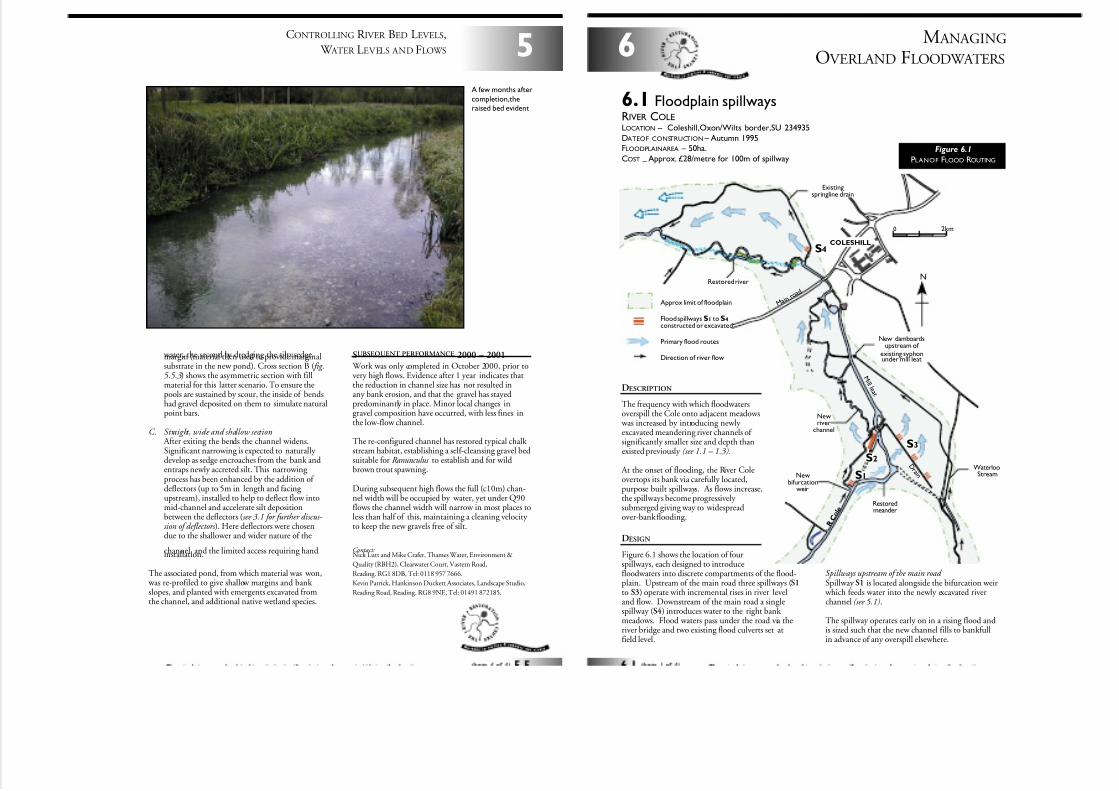
7/27/2019 MAN_mod
http://slidepdf.com/reader/full/manmod 56/84
water, the second by dredging the silty sedgemargin (material then used to provide marginalsubstrate in the new pond). Cross section B ( fig.5.5.3) shows the asymmetric section with fillmaterial for this latter scenario. To ensure thepools are sustained by scour, the inside of bendshad gravel deposited on them to simulate naturalpoint bars.
C. Straight, wide and shallow section After exiting the bends the channel widens.Significant narrowing is expected to naturally develop as sedge encroaches from the bank andentraps newly accreted silt. This narrowing process has been enhanced by the addition of deflectors (up to 5m in length and facing upstream), installed to help to deflect flow intomid-channel and accelerate silt depositionbetween the deflectors (see 3.1 for further discus-sion of deflectors ). Here deflectors were chosendue to the shallower and wider nature of the
channel, and the limited access requiring handinstallation.
The associated pond, from which material was won, was re-profiled to give shallow margins and bank slopes, and planted with emergents excavated fromthe channel, and additional native wetland species.
SUBSEQUENT PERFORMANCE 2000 – 2001
Work was only completed in October 2000, prior tovery high flows. Evidence after 1 year indicates thatthe reduction in channel size has not resulted inany bank erosion, and that the gravel has stayedpredominantly in place. Minor local changes ingravel composition have occurred, with less fines inthe low-flow channel.
The re-configured channel has restored typical chalk stream habitat, establishing a self-cleansing gravel bedsuitable for Ranunculus to establish and for wildbrown trout spawning.
During subsequent high flows the full (c10m) chan-nel width will be occupied by water, yet under Q90flows the channel width will narrow in most places toless than half of this, maintaining a cleaning velocity to keep the new gravels free of silt.
Contact:Nick Lutt and Mike Crafer, Thames Water, Environment &
Quality (RBH2), Clearwater Court, Vastern Road,
Reading. RG1 8DB, Tel: 0118 957 7666.
Kevin Patrick, Hankinson Duckett Associates, Landscape Studio,
Reading Road, Reading. RG8 9NE, Tel: 01491 872185.
5
CONTROLLING R IVER BED LEVELS,
W ATER LEVELS AND FLOWS
A few months after
completion,theraised bed evident
M ANAGING
OVERLAND FLOODWATERS6
6.1 Floodplain spillwaysRIVER COLELOCATION – Coleshill,Oxon/Wilts border,SU 234935
DATEOF CONSTRUCTION – Autumn 1995FLOODPLAINAREA – 50ha.
COST–
Approx. £28/metre for 100m of spillway
0 2km
NRestored river
WaterlooStream
New damboardsupstream of
existing syphonunder mill leat
COLESHILL
Existingspringline drain
Restoredmeander
Newbifurcation
weir
Newriver
channel
R C o l e
M i l l l e a t
D r a i n
S3
S1
S2
S4
Approx limit of floodplain
Flood spillways S1 to S4constructed or excavated
Primary flood routes
Direction of river flow
M a i n r o a
d
DESCRIPTION
The frequency with which floodwatersoverspill the Cole onto adjacent meadows
was increased by introducing newly excavated meandering river channels of significantly smaller size and depth thanexisted previously (see 1.1 – 1.3).
At the onset of flooding, the River Coleovertops its bank via carefully located,purpose built spillways. As flows increase,the spillways become progressively submerged giving way to widespreadover-bank flooding.
DESIGN
Figure 6.1 shows the location of fourspillways, each designed to introducefloodwaters into discrete compartments of the flood-plain. Upstream of the main road three spillways (S1to S3) operate with incremental rises in river leveland flow. Downstream of the main road a singlespillway (S4) introduces water to the right bank meadows. Flood waters pass under the road via theriver bridge and two existing flood culverts set atfield level.
Figure 6.1
PLANOF FLOOD ROUTING
Spillways upstream of the main road Spillway S1 is located alongside the bifurcation weir
which feeds water into the newly excavated riverchannel (see 5.1).
The spillway operates early on in a rising flood andis sized such that the new channel fills to bankfullin advance of any overspill elsewhere.
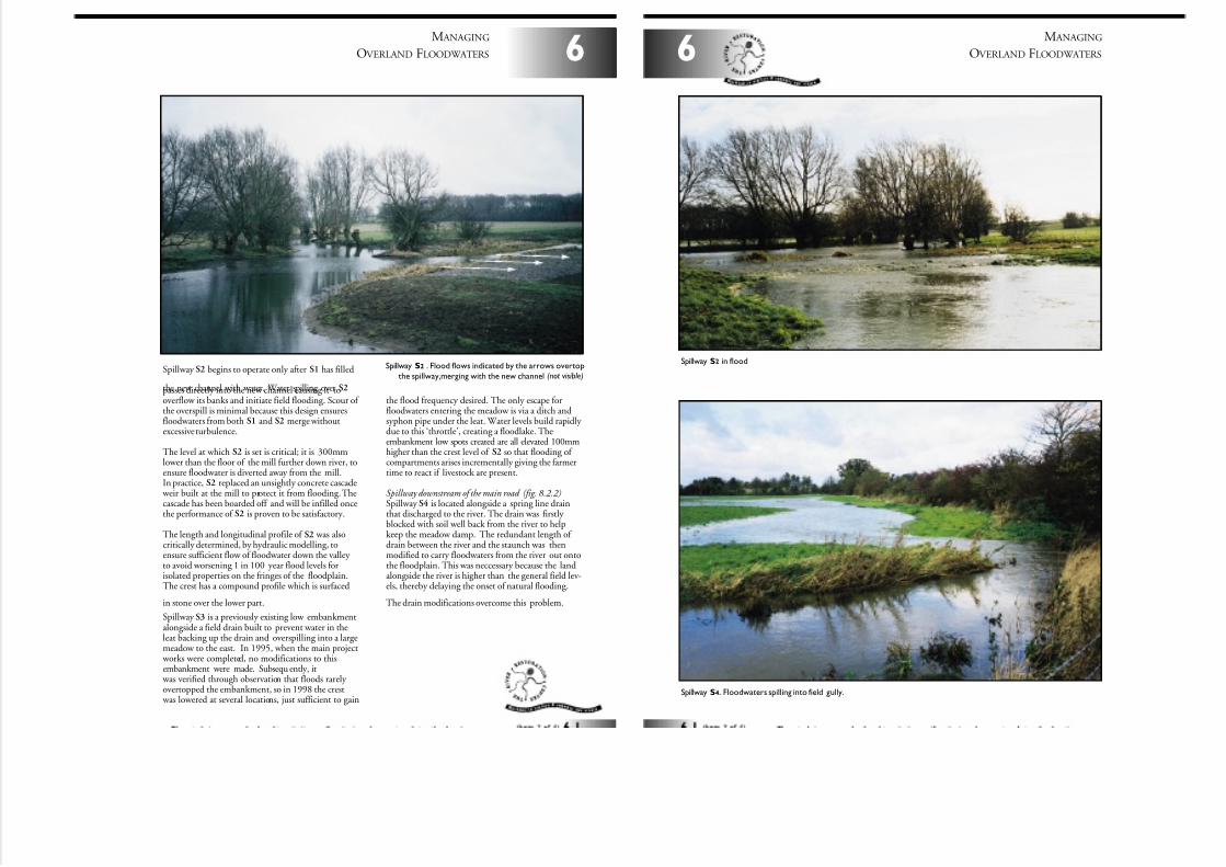
7/27/2019 MAN_mod
http://slidepdf.com/reader/full/manmod 57/84
Spillway S2 begins to operate only after S1 has filled
the new channel with water. Water spilling over S2passes directly into the new channel causing it tooverflow its banks and initiate field flooding. Scour of the overspill is minimal because this design ensuresfloodwaters from both S1 and S2 merge withoutexcessive turbulence.
The level at which S2 is set is critical; it is 300mmlower than the floor of the mill further down river, toensure floodwater is diverted away from the mill.In practice, S2 replaced an unsightly concrete cascade
weir built at the mill to protect it from flooding. Thecascade has been boarded off and will be infilled oncethe performance of S2 is proven to be satisfactory.
The length and longitudinal profile of S2 was alsocritically determined, by hydraulic modelling, toensure sufficient flow of floodwater down the valley to avoid worsening 1 in 100 year flood levels forisolated properties on the fringes of the floodplain.The crest has a compound profile which is surfaced
in stone over the lower part.
Spillway S3 is a previously existing low embankmentalongside a field drain built to prevent water in theleat backing up the drain and overspilling into a largemeadow to the east. In 1995, when the main project
works were completed, no modifications to thisembankment were made. Subsequ ently, it
was verified through observation that floods rarely overtopped the embankment, so in 1998 the crest
was lowered at several locations, just sufficient to gain
6
M ANAGING
OVERLAND FLOODWATERS
Spillway S2 . Flood flows indicated by the arrows overtop
the spillway,merging with the new channel (not visible)
the flood frequency desired. The only escape forfloodwaters entering the meadow is via a ditch andsyphon pipe under the leat. Water levels build rapidly due to this ‘throttle’, creating a floodlake. Theembankment low spots created are all elevated 100mmhigher than the crest level of S2 so that flooding of compartments arises incrementally giving the farmertime to react if livestock are present.
Spillway downstream of the main road (fig. 8.2.2)Spillway S4 is located alongside a spring line drainthat discharged to the river. The drain was firstly blocked with soil well back from the river to helpkeep the meadow damp. The redundant length of drain between the river and the staunch was thenmodified to carry floodwaters from the river out ontothe floodplain. This was neccessary because the landalongside the river is higher than the general field lev-els, thereby delaying the onset of natural flooding.
The drain modifications overcome this problem.
M ANAGING
OVERLAND FLOODWATERS6
Spillway S2 in flood
Spillway S4. Floodwaters spilling into field gully.
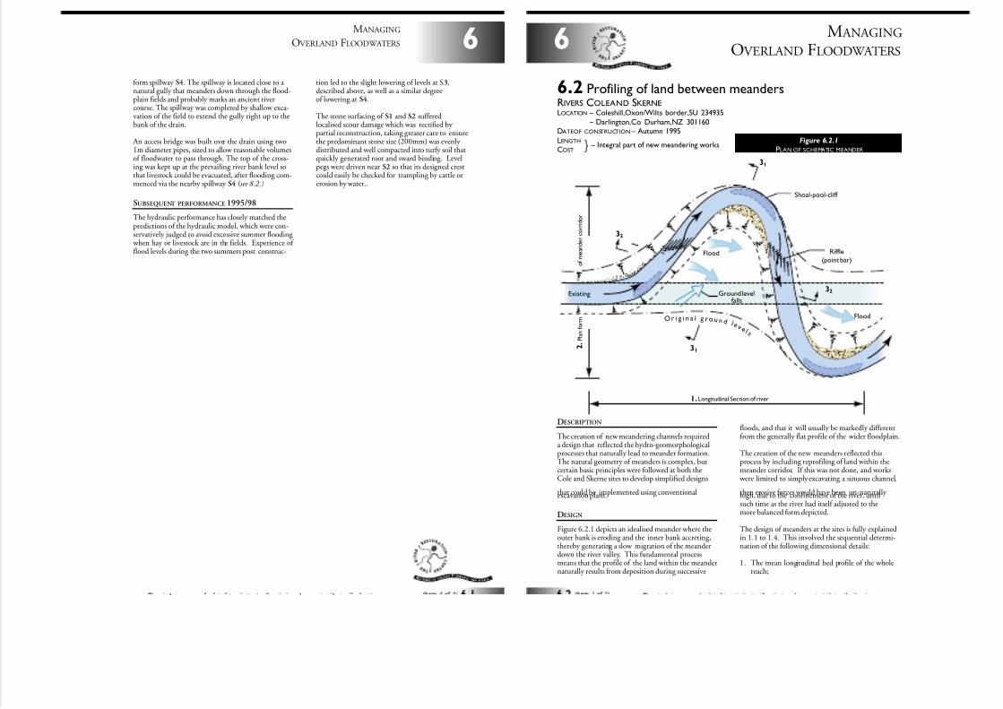
7/27/2019 MAN_mod
http://slidepdf.com/reader/full/manmod 58/84
6
M ANAGING
OVERLAND FLOODWATERS
form spillway S4. The spillway is located close to a natural gully that meanders down through the flood-plain fields and probably marks an ancient rivercourse. The spillway was completed by shallow exca-vation of the field to extend the gully right up to thebank of the drain.
An access bridge was built over the drain using two1m diameter pipes, sized to allow reasonable volumesof floodwater to pass through. The top of the cross-ing was kept up at the prevailing river bank level sothat livestock could be evacuated, after flooding com-menced via the nearby spillway S4 (see 8.2.)
SUBSEQUENT PERFORMANCE 1995/98
The hydraulic performance has closely matched thepredictions of the hydraulic model, which were con-servatively judged to avoid excessive summer flooding
when hay or livestock are in the fields. Experience of flood levels during the two summers post construc-
tion led to the slight lowering of levels at S3,described above, as well as a similar degreeof lowering at S4.
The stone surfacing of S1 and S2 sufferedlocalised scour damage which was rectified by partial reconstruction, taking greater care to ensurethe predominant stone size (200mm) was evenly distributed and well compacted into turfy soil thatquickly generated root and sward binding. Levelpegs were driven near S2 so that its designed crestcould easily be checked for trampling by cattle orerosion by water..
M ANAGING
OVERLAND FLOODWATERS6
DESCRIPTION
The creation of new meandering channels requireda design that reflected the hydro-geomorphologicalprocesses that naturally lead to meander formation.The natural geometry of meanders is complex, butcertain basic principles were followed at both theCole and Skerne sites to develop simplified designs
that could be implemented using conventionalexcavation plant.
DESIGN
Figure 6.2.1 depicts an idealised meander where theouter bank is eroding and the inner bank accreting,thereby generating a slow migration of the meanderdown the river valley. This fundamental processmeans that the profile of the land within the meandernaturally results from deposition during successive
6.2 Profiling of land between meandersRIVERS COLEAND SKERNELOCATION – Coleshill,Oxon/Wilts border,SU 234935
LOCATION – Darlington,Co Durham,NZ 301160DATEOF CONSTRUCTION – Autumn 1995
LENGTH
COST
Shoal-pool-cliff
Ground levelfalls
Riffle
(point bar)
Flood
Flood
O r i g i n a l g r o u n d l e v e l s
Existing
2 .
P l a n f o r m
o f m e a n d e r c o r r i d o r
1. Longitudinal Section of river
32
32
31
31
} – Integral part of new meandering worksFigure 6.2.1
PLAN OF SCHEMATIC MEANDER
floods, and that it will usually be markedly differentfrom the generally flat profile of the wider floodplain.
The creation of the new meanders reflected thisprocess by including reprofiling of land within themeander corridor. If this was not done, and works
were limited to simply excavating a sinuous channel,
then erosive forces would have been un-naturally high, due to the confinement of the river, untilsuch time as the river had itself adjusted to themore balanced form depicted.
The design of meanders at the sites is fully explainedin 1.1 to 1.4. This involved the sequential determi-nation of the following dimensional details:
1. The mean longitudinal bed profile of the wholereach;
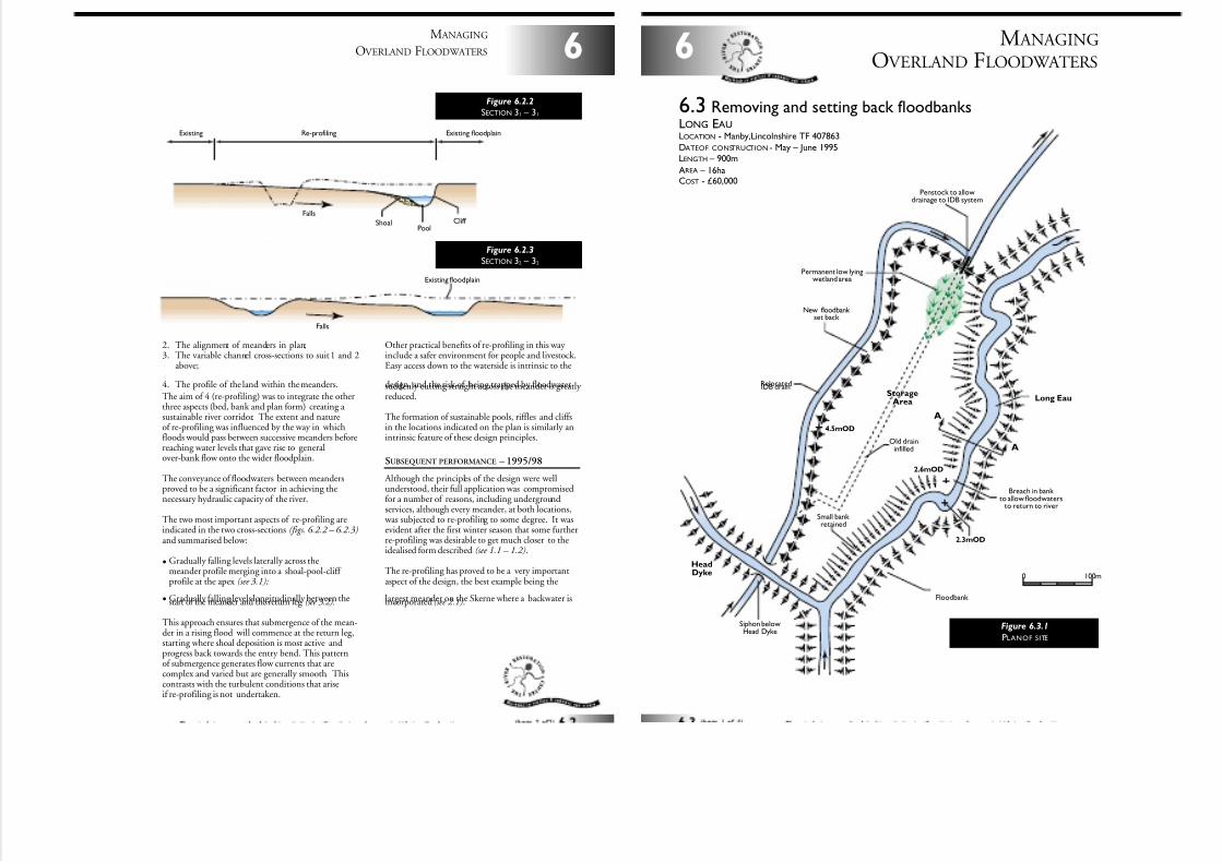
7/27/2019 MAN_mod
http://slidepdf.com/reader/full/manmod 59/84
2. The alignment of meanders in plan;3. The variable channel cross-sections to suit 1 and 2
above;
4. The profile of the land within the meanders.
The aim of 4 (re-profiling) was to integrate the otherthree aspects (bed, bank and plan form) creating a sustainable river corridor. The extent and natureof re-profiling was influenced by the way in whichfloods would pass between successive meanders beforereaching water levels that gave rise to generalover-bank flow onto the wider floodplain.
The conveyance of floodwaters between meandersproved to be a significant factor in achieving thenecessary hydraulic capacity of the river.
The two most important aspects of re-profiling areindicated in the two cross-sections (figs. 6.2.2 – 6.2.3)and summarised below:
• Gradually falling levels laterally across themeander profile merging into a shoal-pool-cliff profile at the apex (see 3.1);
• Gradually falling levels longitudinally between thestart of the meander and the return leg (see 3.2).
This approach ensures that submergence of the mean-der in a rising flood will commence at the return leg,starting where shoal deposition is most active andprogress back towards the entry bend. This patternof submergence generates flow currents that arecomplex and varied but are generally smooth. Thiscontrasts with the turbulent conditions that ariseif re-profiling is not undertaken.
Other practical benefits of re-profiling in this way include a safer environment for people and livestock.Easy access down to the waterside is intrinsic to the
design, and the risk of being trapped by floodwatersuddenly cutting straight across the meander is greatly reduced.
The formation of sustainable pools, riffles and cliffsin the locations indicated on the plan is similarly anintrinsic feature of these design principles.
SUBSEQUENT PERFORMANCE – 1995/98
Although the principles of the design were wellunderstood, their full application was compromisedfor a number of reasons, including undergroundservices, although every meander, at both locations,
was subjected to re-profiling to some degree. It wasevident after the first winter season that some furtherre-profiling was desirable to get much closer to theidealised form described (see 1.1 – 1.2).
The re-profiling has proved to be a very importantaspect of the design, the best example being the
largest meander on the Skerne where a backwater isincorporated (see 2.1).
6
M ANAGING
OVERLAND FLOODWATERS
Re-profiling Existing floodplainExisting
Falls
PoolCliff Shoal
Figure 6.2.2
SECTION 31 – 31
Falls
Existing floodplain
Figure 6.2.3
SECTION 32 – 32
M ANAGING
OVERLAND FLOODWATERS6
6.3 Removing and setting back floodbanksLONG EAULOCATION - Manby,Lincolnshire TF 407863
DATEOF CONSTRUCTION - May – June 1995LENGTH – 900m
AREA – 16haCOST - £60,000
0 100m
StorageArea
HeadDyke
Long Eau
RelocatedIDB drain
Siphon belowHead Dyke
New floodbank set back
Old draininfilled
Penstock to allowdrainage to IDB system
Small bank retained
Breach in bank to allow floodwaters
to return to river
Permanent low lyingwetland area
Floodbank
2.6mOD
2.3mOD
4.5mOD
A
A
Figure 6.3.1
PLANOF SITE
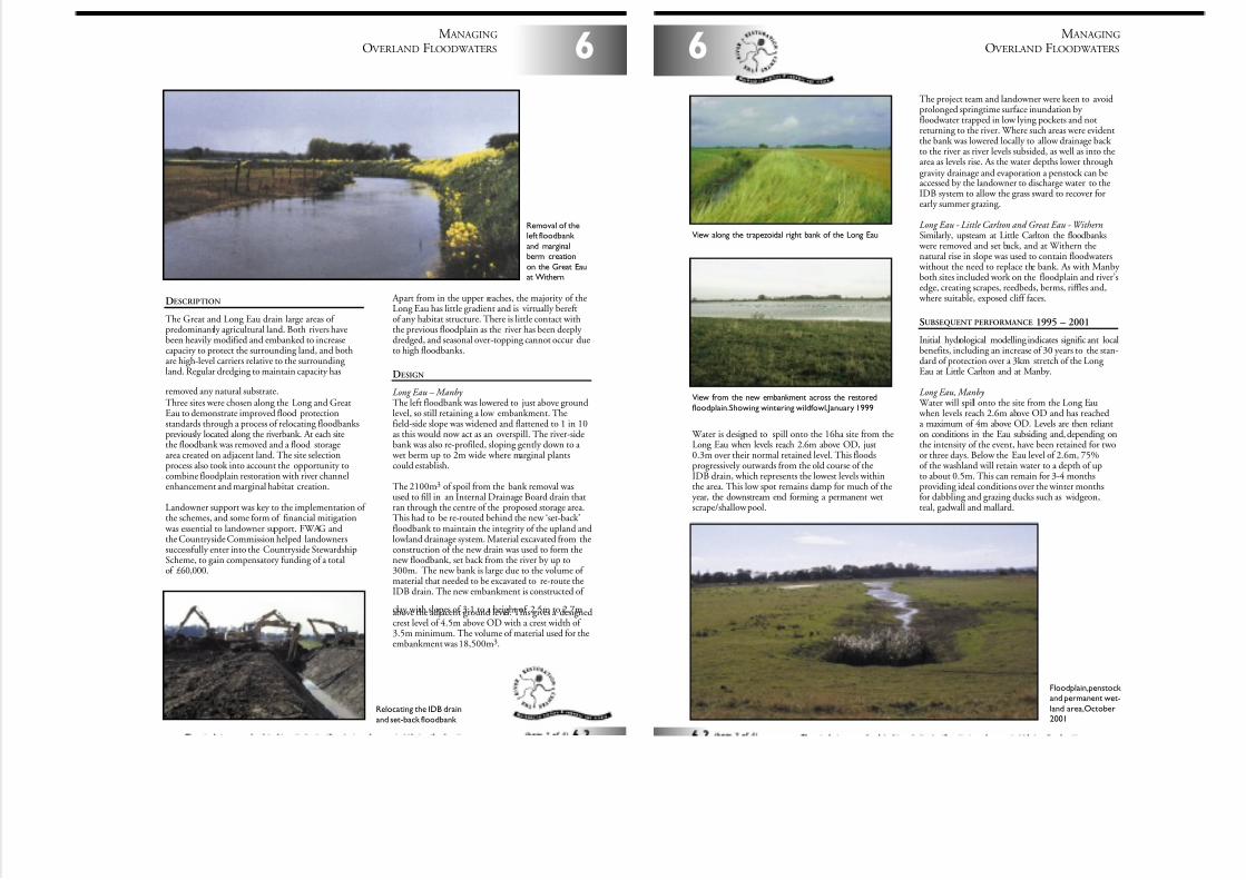
7/27/2019 MAN_mod
http://slidepdf.com/reader/full/manmod 60/84
DESCRIPTION
The Great and Long Eau drain large areas of predominantly agricultural land. Both rivers havebeen heavily modified and embanked to increasecapacity to protect the surrounding land, and bothare high-level carriers relative to the surrounding land. Regular dredging to maintain capacity has
removed any natural substrate.Three sites were chosen along the Long and GreatEau to demonstrate improved flood protectionstandards through a process of relocating floodbankspreviously located along the riverbank. At each sitethe floodbank was removed and a flood storagearea created on adjacent land. The site selectionprocess also took into account the opportunity tocombine floodplain restoration with river channelenhancement and marginal habitat creation.
Landowner support was key to the implementation of the schemes, and some form of financial mitigation
was essential to landowner support. FWAG andthe Countryside Commission helped landownerssuccessfully enter into the Countryside StewardshipScheme, to gain compensatory funding of a totalof £60,000.
Apart from in the upper reaches, the majority of theLong Eau has little gradient and is virtually bereftof any habitat structure. There is little contact withthe previous floodplain as the river has been deeply dredged, and seasonal over-topping cannot occur dueto high floodbanks.
DESIGN
Long Eau – Manby The left floodbank was lowered to just above groundlevel, so still retaining a low embankment. Thefield-side slope was widened and flattened to 1 in 10as this would now act as an overspill. The river-sidebank was also re-profiled, sloping gently down to a
wet berm up to 2m wide where marginal plantscould establish.
The 2100m3 of spoil from the bank removal wasused to fill in an Internal Drainage Board drain thatran through the centre of the proposed storage area.This had to be re-routed behind the new ‘set-back’floodbank to maintain the integrity of the upland andlowland drainage system. Material excavated from theconstruction of the new drain was used to form thenew floodbank, set back from the river by up to300m. The new bank is large due to the volume of material that needed to be excavated to re-route theIDB drain. The new embankment is constructed of
clay with slopes of 3:1 to a height of 2.5m to 2.7mabove the adjacent ground level. This gives a designedcrest level of 4.5m above OD with a crest width of 3.5m minimum. The volume of material used for theembankment was 18,500m3.
6
M ANAGING
OVERLAND FLOODWATERS
Removal of theleft floodbank
and marginalberm creation
on the Great Eauat Withern
Relocating the IDB drain
and set-back floodbank
M ANAGING
OVERLAND FLOODWATERS6
Water is designed to spill onto the 16ha site from theLong Eau when levels reach 2.6m above OD, just0.3m over their normal retained level. This floodsprogressively outwards from the old course of theIDB drain, which represents the lowest levels withinthe area. This low spot remains damp for much of theyear, the downstream end forming a permanent wetscrape/shallow pool.
The project team and landowner were keen to avoidprolonged springtime surface inundation by floodwater trapped in low lying pockets and notreturning to the river. Where such areas were evidentthe bank was lowered locally to allow drainage back to the river as river levels subsided, as well as into thearea as levels rise. As the water depths lower throughgravity drainage and evaporation a penstock can beaccessed by the landowner to discharge water to theIDB system to allow the grass sward to recover forearly summer grazing.
Long Eau - Little Carlton and Great Eau - WithernSimilarly, upsteam at Little Carlton the floodbanks
were removed and set back, and at Withern thenatural rise in slope was used to contain floodwaters
without the need to replace the bank. As with Manby both sites included work on the floodplain and river’sedge, creating scrapes, reedbeds, berms, riffles and,
where suitable, exposed cliff faces.
SUBSEQUENT PERFORMANCE 1995 – 2001
Initial hydrological modelling indicates signific ant localbenefits, including an increase of 30 years to the stan-dard of protection over a 3km stretch of the Long Eau at Little Carlton and at Manby.
Long Eau, Manby Water will spill onto the site from the Long Eau when levels reach 2.6m above OD and has reacheda maximum of 4m above OD. Levels are then relianton conditions in the Eau subsiding and, depending onthe intensity of the event, have been retained for twoor three days. Below the Eau level of 2.6m, 75%of the washland will retain water to a depth of upto about 0.5m. This can remain for 3-4 monthsproviding ideal conditions over the winter monthsfor dabbling and grazing ducks such as widgeon,teal, gadwall and mallard.
View along the trapezoidal right bank of the Long Eau
View from the new embankment across the restored
floodplain.Showing wintering wildfowl,January 1999
Floodplain,penstock and permanent wet-
land area,October2001
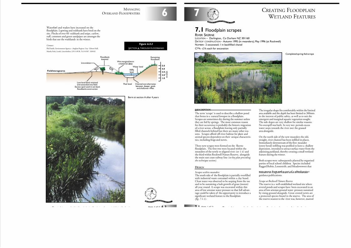
7/27/2019 MAN_mod
http://slidepdf.com/reader/full/manmod 61/84
Waterfowl and waders have increased on thefloodplain. Lapwing and redshank have bred on thesite. Flocks of over 60 redshank and snipe, curlew,ruff, common and green sandpiper are amongst thebirds that use the washlands in the winter.
Contact:
Phil Smith, Environment Agency – Anglian Region, Guy Gibson Hall,
Manby Park, Louth, Lincolnshire, LN11 8UR, Tel: 01507 328102.
6
M ANAGING
OVERLAND FLOODWATERS
Wet marginal bermcreated (1–2m)
Low level bank retainedand extended into field.
Excess spoil used in set-back floodbank construction
Water level
Rifflelevel
Pool level
Floodbank lowered
Live stakes
Remainingfloodbank
Field/storage area
Channel now alternatesbetween deeper poolsand shallower riffles
1.0
3.0
4.0
5.0
2.0 m . O . D .
12
12
Figure 6.3.2
SECTION A THROUGH FLOODBANKS
Berm at section A after 4 years
DESCRIPTION
The term ‘scrape’ is used to describe a shallow pondthat forms in a natural lowspot in a floodplain.Scrapes are sometimes dry during the summer unlessthey are fed by springs. The most common reasonfor their occurrence is probably the historic migrationof a river across a floodplain leaving only partially filled channels behind but there are many other rea-sons. Scrapes afford off-river habitat for plant andanimal species dependent on their unique characteris-tics, including frogs and newts.
Three new scrapes were formed on the Skernefloodplain. The first two were located within themeanders of the newly re-aligned river (see 1.4) andthe third within Rockwell Nature Reserve, alongsidethe main east coast railway line (see key plan preceding the technique section).
DESIGN
Scrapes within meanders The south side of the floodplain is partially overfilled
with industrial waste contained within a clay bund.Clean water was observed to be seeping from the toeand to be sustaining a lush growth of grass (mown)all year round. A scrape was excavated within thisarea of low artesian water pressure so that full advan-tage could be taken of the opportunity to introduce a significant wetland feature to the floodplain(fig. 7.1.1).
CREATING FLOODPLAIN
W ETLAND FEATURES7
7.1 Floodplain scrapesRIVER SKERNELOCATION – Darlington, Co Durham NZ 301160DATEOF CONSTRUCTION – Autumn 1995 (in meanders), May 1996 (at Rockwell)
NUMBER – 2 excavated; 1 in backfilled chanel
COSt– £1k each for excavation
Completed spring-fed scrape
The irregular shape fits comfortably within the limitedarea available and the depth has been limited to 300mmin the interest of public safety, as well as to suit theemergent and marginal aquatic vegetation sought.The side slopes are very shallow for similar reasons.No overspill was built. In very wet periods excess
water seeps towards the river over the grassedarea alongside.
On the north side of the new meanders the old,straight, river channel has been infilled in places.Immediately downstream of the first meander(entry bend) infilling was profiled to leave a shallow depression, intended to attract surface water from theadjoining parkland, thereby creating a small wetlandfeature during the winter.
Both scrapes were subsequently planted by organisedparties of local school children. Species includedRagged Robin, Loosestrife, and Meadowsweet that
were grown from seed as part of a school projectlinked to an English Nature series of freshwaterguidance publications.
Scrape at Rockwell Nature Reserve The reserve is a well-established wetland site whereseveral ponds and scrapes have been excavated in anarea of low artesian ground water pressure sustainedby rising ground alongside. Great crested newts area protected species found in the reserve. The area of the reserve nearest to the river was, however, marred
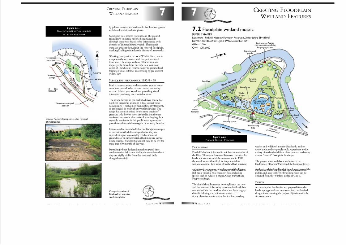
7/27/2019 MAN_mod
http://slidepdf.com/reader/full/manmod 62/84
by piles of dumped soil and rubble that have overgrown with less desirable ruderial plants.
Some piles were cleared from site and the groundtaken down to expose historic floodplain soils,although these were found to be interspersed withdeposits of dumped foundry sand. These sands
were also evident throughout the restored floodplain,marking Darlington’s industrial history of iron works.
Working closely with the local Wildlife Trust, a new scrape was then excavated and the spoil removedfrom site. The scrape is about 50m2 in area andslopes gently down from one side to a maximumdepth of 1m where it returns steeply to ground levelforming a small cliff that is overhung by pre-existent
willow carr.
SUBSEQUENT PERFORMANCE 1995/6 – 98
Both scrapes excavated within artesian ground waterareas have proved to be very successful, sustaining
wetland habitat year round and providing visualinterest to previously unremarkable areas.
The scrape formed in the backfilled river course hasnot been successful, although it does collect wateroccasionally. This has not been sufficiently frequent,or prolonged, to establish any wetland plants. Thescrape has been colonised by the same species of grass and wild flowers sown around it, but they are
weakened as a result of occasional waterlogging. It isarguably a nuisance in this public open space since itprovides no discernible ecological or amenity benefits.
It is reasonable to conclude that for floodplain scrapesto provide worthwhile ecological value they aredependent upon a reasonably reliable source of groundwater or surface water, albeit most are intrin-sically seasonal features that do not have to be wet formore than 6-9 months of the year.
Surprisingly both duck and moorhen spend timeon the artesian fed scrape within the meanders wherethey are highly visible from the new path builtalongside (see 8.4).
7
CREATING FLOOPLAIN
W ETLAND FEATURES
0 10m
N
( b u n d e d
l a n d f i l l )
e d g
e
o f f l o o
d p l a i n
Artesiansprings
R.Skerne
New scrapeexcavated
New conctrete path(see 8.3)
4 2 m
c o n
t o u r
4 3 m c o n t o u r
T o po f new m e a n d e
r i n g r
i v e r
b a n k
4 1. 5 m
4 1 . 4 m
41.2m
41.3m
41.2m
Comparitive view of
Rockwell scrape afterwork completed
View of Rockwell scrape site after removal
of rubble piles
Figure 7.1.1
PLAN OF SCRAPE WITHIN MEANDER
FED BY GROUNDWATER
CREATING FLOODPLAIN
W ETLAND FEATURES
7.2 Floodplain wetland mosaicRIVER THAMESLOCATION - Pinkhill Meadow,Farmoor Reservoir,Oxfordshire SP 439067
DATEOF CONSTRUCTION - JUNE 1990, December 1991AREA – 1.5ha
COST - £112,000
DESCRIPTION
Pinkhill Meadow is located in a 4 hectare meander of the River Thames at Farmoor Reservoir. In a detailedlandscape assessment of the reservoir site in 1988the meadow was identified for its potential for
wetland creation. Few areas of wetland had survived
agricultural improvement in this part of the UpperThames Valley. Approx. 1.5 hectares of the meadow still had a valuable relic meadow flora including species such as Adders Tongue, Great Burnett andPepper-saxifrage.
The aim of the scheme was to compliment the riverand the reservoir habitats by restoring the floodplain
wetland within the meadow which had been largely disturbed during reservoir construction.
A key objective was to restore habitat for breeding
waders and wildfowl, notably Redshank, and tocreate a place where people could experience a widevariety of wetland wildlife at close quarters and enjoy a more “natural” floodplain landscape.
The project was a collaboration between thelandowners (Thames Water) and the National Rivers
Authority, advised by Pond Action. Large parts of theFarmoor wetland complex are open to members of public, and keys to the birdwatching hides can beobtained from the Wardens Lodge at Gate 3.
DESIGN
A concept plan for the site was prepared from thelandscape appraisal and developed into the detaileddesign, incorporating the project objectives with thesite constraints.
7
N
GrazingMeadow
Experimentalponds
Environment Agencyinstrumentation building
for gauging station
WetMeadow
Main pond andGravel island
Waderscrape
Reed pool
Thorney scrub
R e s e r v o i r p e r i m e t e r r o a d
Birdwatchinghide
Mudbank
Reedpool
Gravel area
Reedbed
Reed bed
Towpath
F a r m o o r R e s e r v o i r
R i v e r
T h a m
e s
Publicfootpath
Figure 7.2.1
PLANOF PINKHILL MEADOW
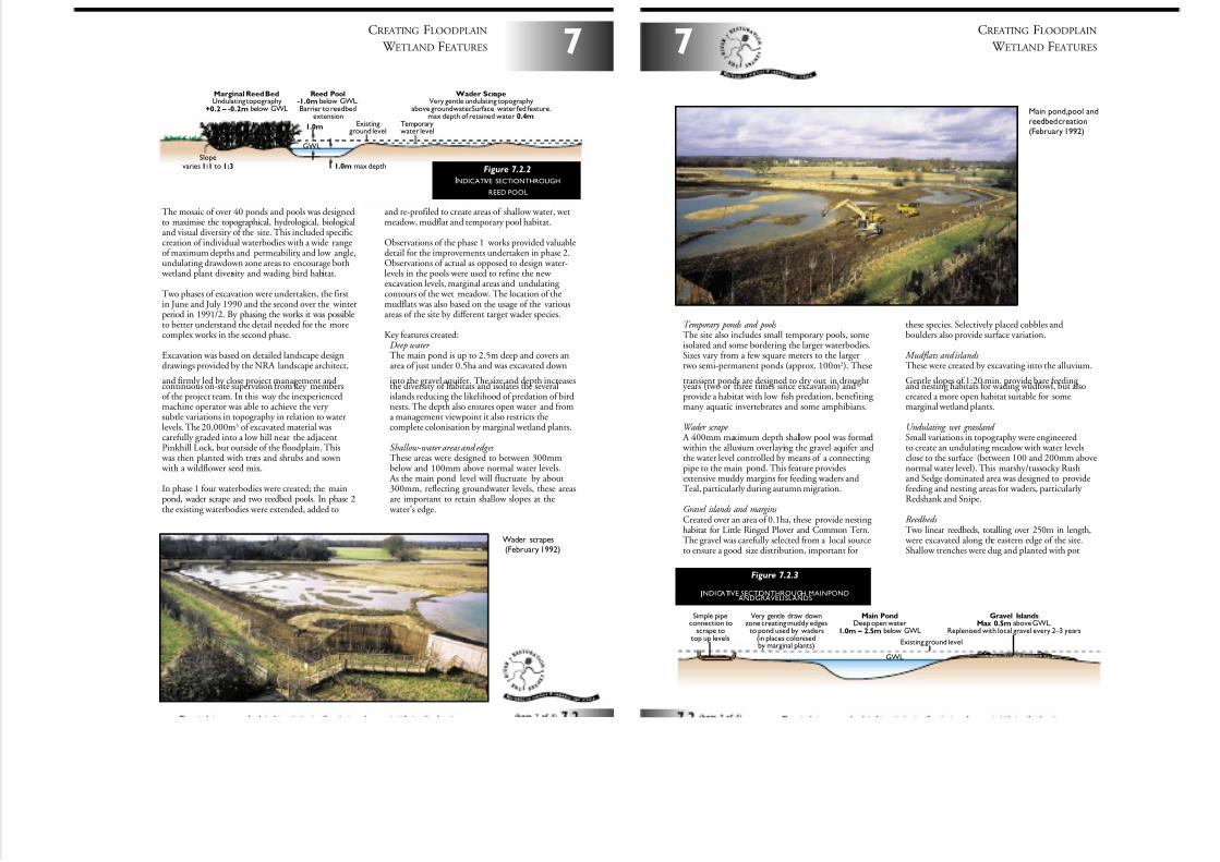
7/27/2019 MAN_mod
http://slidepdf.com/reader/full/manmod 63/84
7
CREATING FLOODPLAIN
W ETLAND FEATURES
The mosaic of over 40 ponds and pools was designedto maximise the topographical, hydrological, biologicaland visual diversity of the site. This included specificcreation of individual waterbodies with a wide rangeof maximum depths and permeability, and low angle,undulating drawdown zone areas to encourage both
wetland plant diversity and wading bird habitat.
Two phases of excavation were undertaken, the firstin June and July 1990 and the second over the winterperiod in 1991/2. By phasing the works it was possibleto better understand the detail needed for the morecomplex works in the second phase.
Excavation was based on detailed landscape designdrawings provided by the NRA landscape architect,
and firmly led by close project management andcontinuous on-site supervision from key membersof the project team. In this way the inexperiencedmachine operator was able to achieve the very subtle variations in topography in relation to waterlevels. The 20,000m3 of excavated material wascarefully graded into a low hill near the adjacentPinkhill Lock, but outside of the floodplain. This
was then planted with trees and shrubs and sown with a wildflower seed mix.
In phase 1 four waterbodies were created; the mainpond, wader scrape and two reedbed pools. In phase 2the existing waterbodies were extended, added to
and re-profiled to create areas of shallow water, wetmeadow, mudflat and temporary pool habitat.
Observations of the phase 1 works provided valuabledetail for the improvements undertaken in phase 2.Observations of actual as opposed to design water-levels in the pools were used to refine the new excavation levels, marginal areas and undulating contours of the wet meadow. The location of themudflats was also based on the usage of the variousareas of the site by different target wader species.
Key features created:Deep water The main pond is up to 2.5m deep and covers anarea of just under 0.5ha and was excavated down
into the gravel aquifer. The size and depth increasesthe diversity of habitats and isolates the severalislands reducing the likelihood of predation of birdnests. The depth also ensures open water and froma management viewpoint it also restricts thecomplete colonisation by marginal wetland plants.
Shallow-water areas and edges These areas were designed to between 300mmbelow and 100mm above normal water levels.
As the main pond level will fluctuate by about300mm, reflecting groundwater levels, these areasare important to retain shallow slopes at the
water’s edge.
1.0m max depth
1.0m Temporarywater level
Existingground level
Slopevaries 1:1 to 1:3
Reed Pool-1.0m below GWL.Barrier to reedbed
extension
Marginal Reed BedUndulating topography
+0.2 – -0.2m below GWL
Wader ScrapeVery gentle undulating topography
above groundwater.Surface water fed feature.max depth of retained water 0.4m
GWL
Figure 7.2.2
INDICATIVE SECTIONTHROUGH
REED POOL
Wader scrapes(February 1992)
Temporary ponds and pools The site also includes small temporary pools, someisolated and some bordering the larger waterbodies.Sizes vary from a few square meters to the largertwo semi-permanent ponds (approx. 100m2). These
transient ponds are designed to dry out in droughtyears (two or three times since excavation) andprovide a habitat with low fish predation, benefiting many aquatic invertebrates and some amphibians.
Wader scrape A 400mm maximum depth shallow pool was formed within the alluvium overlaying the gravel aquifer andthe water level controlled by means of a connecting pipe to the main pond. This feature providesextensive muddy margins for feeding waders andTeal, particularly during autumn migration.
Gravel islands and margins Created over an area of 0.1ha, these provide nesting habitat for Little Ringed Plover and Common Tern.The gravel was carefully selected from a local sourceto ensure a good size distribution, important for
these species. Selectively placed cobbles andboulders also provide surface variation.
Mudflats and islands These were created by excavating into the alluvium.
Gentle slopes of 1:20 min. provide bare feeding and nesting habitats for wading wildfowl, but alsocreated a more open habitat suitable for somemarginal wetland plants.
Undulating wet grassland Small variations in topography were engineeredto create an undulating meadow with water levelsclose to the surface (between 100 and 200mm abovenormal water level). This marshy/tussocky Rushand Sedge dominated area was designed to providefeeding and nesting areas for waders, particularly Redshank and Snipe.
Reedbeds Two linear reedbeds, totalling over 250m in length,
were excavated along the eastern edge of the site.Shallow trenches were dug and planted with pot
CREATING FLOODPLAIN
W ETLAND FEATURES
7
Main pond,pool andreedbed creation(February 1992)
Existing ground level
GWL
Main Pond
Deep open water1.0m – 2.5m below GWL
Gravel Islands
Max 0.5m above GWL.Replenised with local gravel every 2 – 3 years
Very gentle draw downzone creating muddy edges
to pond used by waders(in places colonisedby marginal plants)
Simple pipeconnection to
scrape totop up levels
Figure 7.2.3
INDICATIVE SECTIONTHROUGH MAINPONDANDGRAVELISLANDS
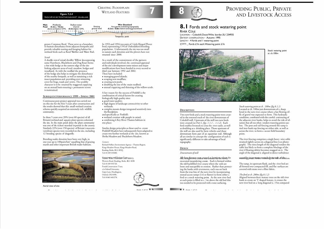
7/27/2019 MAN_mod
http://slidepdf.com/reader/full/manmod 64/84
Existingground level
Temporary pools
Shallow waterchannel
-0.5m below GWL
Mudbanks-0.2m – +0.2m
above and below GWL
Main
Pond
GWL
Wet Grassland
Very gentle undulating topography-0.3m – 0.8m below existing ground level
grown Common Reed. These serve as a boundary to human disturbance from adjacent footpaths andprovide valuable nesting and foraging habitat for
wetland birds such as Reed Warbler and Water Rail.
Scrub A double row of mixed shrubby Willow (incorporating some Hawthorn, Blackthorn and Dog Rose) formsa 4m wide hedge at the eastern edge of the sitelinking adjacent areas of reed, meadow, hedges and
woodland. As with the reedbed the presenceof the hedge also helps to mitigate the disturbanceof the nearby footpath, as well as sustaining a richinsect population and providing over-wintering cover for frogs, toads and newts. The scrubby character is to be retained by staggered coppicing on an annual basis ensuring a permanent screenis maintained.
SUBSEQUENT PERFORMANCE 1999 – SPRING 2001
Continuous post-project appraisal was carried outon this site for the first 5 years after construction andthe results showed that this small wetland creationscheme quickly acquired an extremely rich wildlifecommunity.
In these 5 years over 20% (over 60 species) of allBritain’s wetland and aquatic plant species colonisedthe site. In the main pond alone the plant community
was one of the richest recorded in ponds in the county.Similarly 22% (over 150 species) of Britain’s macroin-vertebrate species were recorded on the site, including 12 breeding species of dragonfly.
Breeding wader densities have been very high, inone year up to 100pairs/km2 equalling that of grazing marsh and other important British wader habitats.
In 1993 and 1994 two pairs of Little Ringed Ploverbred, representing 15% of Oxfordshire’s breeding population . Unfortunately the site was too smallto sustain such densities and the plovers have notreturned since 2000.
As a result of the commitment of the partnersand individuals involved, the continued appraisalof the site’s development some minor and majormodifications have been funded in every second orthird year between 1992 and 2002.These have included:
• managing gravel islands;
• scraping new mudflats;
• creating new pools;
• doubling the size of the main reedbed;
• annual coppicing and thinning of the willow scrub.
A key reason for the success of Pinkhill is thecombination of critical factors for creating biologically high quality sites:
• good water quality;
• high degree of landscape connectivity to other wetlands;
• complex mosaic design integrated sensitively intothe floodplain;
and specifically at Pinkhill;
• wetland creation with people in mind;
• combining 6 Key River Thames habitats inone place;
Similar design principles as those used to createPinkhill Meadow have subsequently been adapted tocreate two further wetlands at the site, known asShrike Meadow and Buckthorn Meadow.
Contacts:
Richard Hellier, Environment Agency – Thames Region,
Kings Meadow House, Kings Meadow Road,
Reading, Berks, RG1 8DQ.
Tel: 01189 535000.
Conservation and Heritage Team,Thames Water, Clearwater Court (RBH2),
Western Road, Reading, Berks, RG1 8DB
Tel: 01189 593720.
Ponds Conservation Trust,
c/o Oxford University,
Gipsy Lane, Headington,
Oxford, OX3 0PB.
Tel: 01865 483278.
7
CREATING FLOODPLAIN
W ETLAND FEATURESFigure 7.2.4
INDICATIVE SECTIONTHROUGHWET GRASSLAND
Aerial view of site
PROVIDING PUBLIC, PRIVATE
AND LIVESTOCK A CCESS8
8.1 Fords and stock watering pointRIVER COLELOCATION – Coleshill,Oxon/Wilts border,SU 234935
DATEOF CONSTRUCTION – Autumn 1995LENGTH – 4 fords and 1 watering point
COSTS–
Fords £1k each.Watering point £1k
Stock watering point
at ch.100m
DESCRIPTION
Two new fords and a stock watering point were creat-ed in the restored reach of the river downstream of Coleshill mill. Upstream of the mill two new fords
were created (see Part 1, figs. 1.1.1 – 1.1.2). Eachford enables livestock to cross the river easily, as wellas doubling as a drinking place. Those upstream of the mill are also used by farm vehicles and thosedownstream form part of an equestrian trail. Althoughall are similar in concept the configuration of each issignificantly different to take advantage of localtopography.
DESIGN
Downstream of mill
All three features were created at locations where theold, straight river course was crossed by the newly excavated meandering course. Each is formed withinthe old backfilled river course where the soils areloose and susceptible to erosion. Rather than protect-ing the banks with revetments, each was set back from the true line of the new river by incorporating stoned access ramps (1:6 or flatter) to form either a ford or a stock watering point. As the new river bedat each point is filled to c. 1m above the old bed thistoo needed to be protected with s tone surfacing.
Stock watering point at ch. 100m (fig.8.1.1)Located at ch. 100m just downstream of a sharpbend in the new river course where a fast flowing rif-fle of gravel was expected to form. This hydrauliccondition, combined with the careful contouring of the adjacent river banks, helps to avoid the risk of sil-tation that all too often renders watering points use-less. The post and rail fencing around the ramp istied into bank top fencing on either side, as well asacross the river, to form a secure field boundary point.
The river fencing comprises a single heavy wire cablestrained tightly across on a diagonal line (s ee photo-graph). The extra length of the diagonal renders thecable less likely to form a complete blockage of theriver if floating debris becomes snagged on it. Theangle of the diagonal is aligned to direct turbulence
caused by its presence towards the mouth of the watering point, further reducing the risk of siltation.
The ramp, its upstream flank, and the river bed areall formed over compacted fill, and flat surfaces arecovered with stone over a filter fabric.
The ford at ch. 280m (fig.8.1.2) Aligned between three mature trees on the old riverbank to create an ‘S’ shaped feature, it crosses thenew river bed on a long diagonal (c. 15m compared
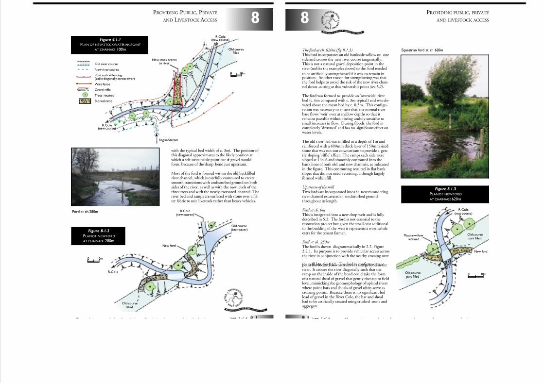
7/27/2019 MAN_mod
http://slidepdf.com/reader/full/manmod 65/84
New ford
Old coursefilled
Old course(backwater)
R.Cole(new course)
R.Cole
0 10m
Figure 8.1.2
PLANOF NEWFORD
AT CHAINAGE 280m
8
PROVIDING PUBLIC, PRIVATE
AND LIVESTOCK A CCESS
Raglan Stream
New stock accessto river
Old coursefilled
R.Cole(new course)
R.Cole(new course)
Old river course
New river course
Post and rail fencing(cable diagonally across river)
Wire fence
Gravel riffle
Trees retained
Stoned ramp
0 10m
Figure 8.1.1
PLAN OF NEW STOCKWATERINGPOINT
AT CHAINAGE 100m
Ford at ch.280m
with the typical bed width of c. 3m). The position of this diagonal approximates to the likely position at
which a self-sustainable point bar of gravel wouldform, because of the sharp bend just upstream.
Most of the ford is formed within the old backfilledriver channel, which is carefully contoured to createsmooth transitions with undisturbed ground on bothsides of the river, as well as with the root levels of thethree trees and with the newly excavated channel. Theriver bed and ramps are surfaced with stone over a fil-ter fabric to suit livestock rather than heavy vehicles.
PROVIDING PUBLIC, PRIVATE
AND LIVESTOCK ACCESS8
The ford at ch. 620m (fig.8.1.3)This ford incorporates an old bankside willow on oneside and crosses the new river course tangentially.This is not a natural gravel deposition point in theriver (unlike the examples above) so the ford needed
to be artificially strengthened if it was to remain inposition. Another reason for strengthening was thatthe ford helps to avoid the risk of the new river chan-nel down-cutting at this vulnerable point (see 1.2).
The ford was formed to provide an ‘overwide’ riverbed (c. 6m compared with c. 3m typical) and was ele-vated above the mean bed by c. 0.3m. This configu-ration was necessary to ensure that the normal riverbase flows ‘weir’ over at shallow depths so that itremains passable without being unduly sensitive tosmall increases in flow. During floods, the ford iscompletely ‘drowned’ and has no significant effect on
water levels.
The old river bed was infilled to a depth of 1m andreinforced with a 400mm thick layer of 150mm sizedstone that was run-out downstream to provide a gen-tly sloping ‘riffle’ effect. The ramps each side weresloped at 1 in 6 and smoothly contoured into thebank lines of both old and new channels, as indicatedin the figure. This contouring resulted in flat bank slopes that did not need revetting, although largely formed within fill.
Upstream of the mill Two fords are incorporated into the new meandering river channel excavated in undisturbed groundthroughout its length.
Ford at ch. 0mThis is integrated into a new drop weir and is fully described in 5.2. The ford is not essential to therestoration project but given the small cost additionalto the building of the weir it represents a worthwhileextra for the tenant farmer.
Ford at ch. 250mThe ford is shown diagrammatically in 2.2, Figure2.2.1. Its purpose is to provide vehicular access acrossthe river in conjunction with the nearby crossing over
the mill leat (see 8.2). The ford is configured as a point bar located downstream of a sharp bend in theriver. It crosses the river diagonally such that theramp on the inside of the bend could take the formof a natural shoal of gravel that gently rises up to fieldlevel, mimicking the geomorphology of upland rivers
where point bars and shoals of gravel often serve ascrossing points. Because there is no significant bedload of gravel in the River Cole, the bar and shoalhad to be artificially created using crushed stone andaggregate.
New ford
Mature willowretained
Old coursepart filled
Old coursepart filled
R.Cole(new course)
0 10m
Equestrian ford at ch 620m
Figure 8.1.3
PLANOF NEWFORD
AT CHAINAGE 620m
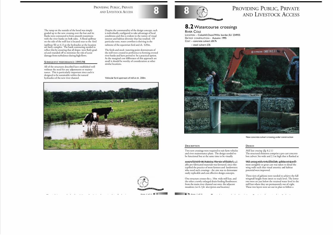
7/27/2019 MAN_mod
http://slidepdf.com/reader/full/manmod 66/84
8
PROVIDING PUBLIC, PRIVATE
AND LIVESTOCK A CCESS
The ramp on the outside of the bend was simply graded up to the new crossing over the leat and itsflanks were contoured to form smooth transitions
with the river banks on both sides. A flood spillway on the side of the mill leat is located near to the ford
(spillway S2 see 6.1) so the hydraulics at the locationare fairly complex. The bank contouring needed toreflect this by ensuring that all slopes were flatly grad-ed and rounded off to minimise the risk of scourdamage from turbulence during high flows.
SUBSEQUENT PERFORMANCE 1995/98
All of the structures described have established well without the need for any adjustments or mainte-nance. This is particularly important since each isdesigned to be sustainable within the naturalhydraulics of the new river channel.
Despite the commonality of the design concept, eachis individually configured to take advantage of localconditions and this is evident in the variety of visualinterest and habitat diversity that has resulted. Of particular note, water crowfoot is thriving in the
tailstone of the equestrian ford and ch. 620m.
The fords and stock watering point downstream of the mill were created in preference to forming revetedriver banks and have proved to be a practical option.
As the marginal cost differences of this approach aresmall it should be worthy of consideration at othersimilar locations.
Vehicular ford upstream of mill at ch. 250m
DESCRIPTION
Two new crossings were required to suit farm vehiclesand river maintenance plant. The design needed tobe functional but at the same time to be visually
acceptable without incurring excessive additionalcosts to achieve this balance. The use of readily avail-able pre-fabricated materials was favoured, since thistypified the practice of most farmers and landowners
who need such crossings - the aim was to demostrateeasily replicable and cost effective design concepts.
One structure crosses the c. 10m wide mill leat, andthe other a newly enlarged drain feeding floodwatersfrom the main river channel out onto the adjacentmeadows (see 6.1 for description and location).
DESIGN
Mill leat crossing (fig. 8.2.1)The structural elements comprise a pre-cast concretebox culvert 3m wide and 2.1m high that is flanked at
each corner with stone filled box gabion wing walls.This arrangement is functionally satisfactory but ismost unsightly so great care was taken to detail the
wing walls such that visual amenity and habitatpotential were improved.
Three tiers of gabions were needed to achieve the full wingwall height from invert to track level. The lowertwo were set just below the retained water level in themill leat where they are permanently out of s ight.These two layers were set out in plan to follow a
PROVIDING PUBLIC, PRIVATE
AND LIVESTOCK A CCESS8
8.2Watercourse crossingsRIVER COLELOCATION – Coleshill,Oxon/Wilts border,SU 234935
DATEOF CONSTRUCTION – Autumn 1995COST – concrete culvert £8.7k
COST – steel culvert £3k
New concrete culvert crossing under construction
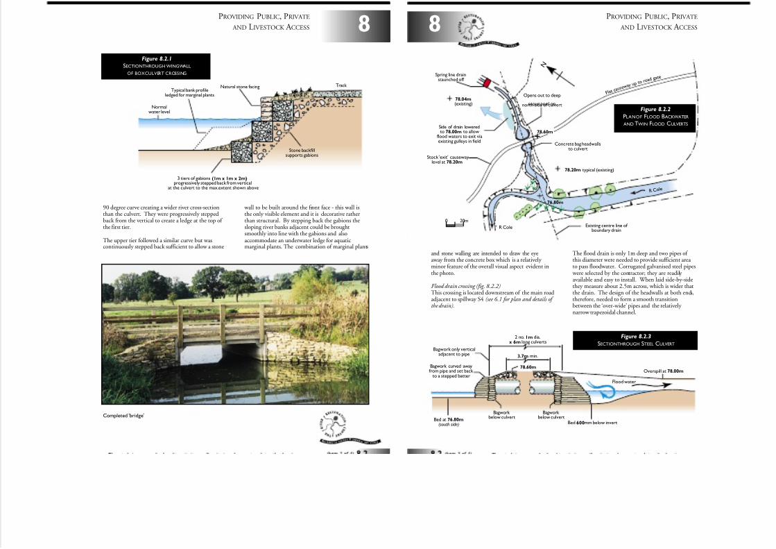
7/27/2019 MAN_mod
http://slidepdf.com/reader/full/manmod 67/84
8
PROVIDING PUBLIC, PRIVATE
AND LIVESTOCK A CCESS
90 degree curve creating a wider river cross-sectionthan the culvert. They were progressively steppedback from the vertical to create a ledge at the top of the first tier.
The upper tier followed a similar curve but wascontinuously stepped back sufficient to allow a stone
wall to be built around the front face - this wall isthe only visible element and it is decorative ratherthan structural. By stepping back the gabions thesloping river banks adjacent could be broughtsmoothly into line with the gabions and alsoaccommodate an underwater ledge for aquaticmarginal plants. The combination of marginal plants
Natural stone facing
Normalwater level
Stone backfillsupports gabions
Track
3 tiers of gabions (1m x 1m x 2m)progressively stepped back from vertical
at the culvert to the max.extent shown above
Typical bank profileledged for marginal plants
Figure 8.2.1
SECTIONTHROUGH WINGWALL
OF BOXCULVERT CROSSING
Completed ‘bridge’
and stone walling are intended to draw the eyeaway from the concrete box which is a relatively minor feature of the overall visual aspect evident inthe photo.
Flood drain crossing (fig. 8.2.2)This crossing is located downstream of the main roadadjacent to spillway S4 (see 6.1 for plan and details of the drain).
The flood drain is only 1m deep and two pipes of this diameter were needed to provide sufficient area to pass floodwater. Corrugated galvanised steel pipes
were selected by the contractor; they are readily available and easy to install. When laid side-by-sidethey measure about 2.5m across, which is wider thatthe drain. The design of the headwalls at both ends,therefore, needed to form a smooth transitionbetween the ‘over-wide’ pipes and the relatively narrow trapezoidal channel.
PROVIDING PUBLIC, PRIVATE
AND LIVESTOCK A CCESS8
2 no. 1m dia.x 6m long culverts
3.7m min.
Bagwork only verticaladjacent to pipe
Bagwork curved awayfrom pipe and set back
to a stepped batter
Bed at 76.80m(south side)
78.60m
Bagwork below culvert
Bed 600mm below invert
Overspill at 78.00m
Bagwork below culvert
Flood water
Figure 8.2.3
SECTIONTHROUGH STEEL CULVERT
Concrete bag headwallsto culvert
Existing centre line of boundary drain
78.20m typical (existing)
76.80m
R C o l e
78.04m(existing)
Spring line drainstaunched off
Side of drain loweredto 78.00m to allow
flood waters to exit viaexisting gulleys in field
Stock 'exit' causewaylevel at 78.20m
R Cole
Opens out to deep
scour pool onnorth side of culvert
F l a tc a u s e w
a y u p t o r o a dg a t e
78.60m
N
0 20m
Figure 8.2.2
PLANOF FLOOD BACKWATER
AND TWIN FLOOD CULVERTS
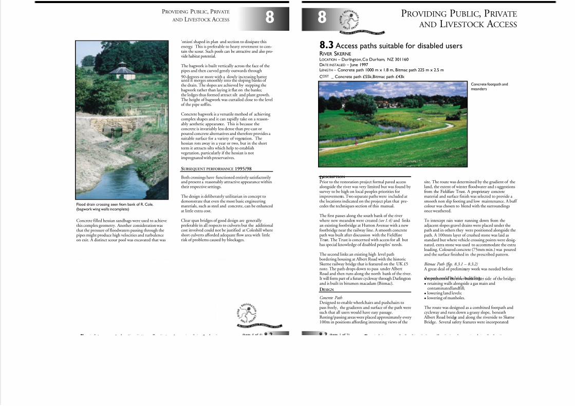
7/27/2019 MAN_mod
http://slidepdf.com/reader/full/manmod 68/84
Concrete filled hessian sandbags were used to achievethis complex geometry . Another consideration wasthat the pressure of floodwaters passing through thepipes might produce high velocities and turbulenceon exit. A distinct scour pool was excavated that was
8
PROVIDING PUBLIC, PRIVATE
AND LIVESTOCK A CCESS
Flood drain crossing seen from bank of R. Cole.(bagwork wing walls incomplete)
‘onion’ shaped in plan and section to dissipate thisenergy. This is preferable to heavy revetment to con-tain the scour. Such pools can be attractive and also pro-vide habitat potential.
The bagwork is built vertically across the face of thepipes and then curved gently outwards through
90 degrees or more with a slowly increasing batteruntil it merges smoothly into the sloping banks of the drain. The slopes are achieved by stepping thebagwork rather than laying it flat on the banks;the ledges thus formed attract silt and plant growth.The height of bagwork was curtailed close to the levelof the pipe soffits.
Concrete bagwork is a versatile method of achieving complex shapes and it can rapidly take on a reason-ably aesthetic appearance. This is because theconcrete is invariably less dense than pre-cast orpoured concrete alternatives and therefore provides a suitable surface for a variety of vegetation. Thehessian rots away in a year or two, but in the shortterm it attracts silts which help to establishvegetation, particularly if the hessian is notimpregnated with preservatives.
SUBSEQUENT PERFORMANCE 1995/98
Both crossings have functioned entirely satisfactorily and present a reasonably attractive appearance withintheir respective settings.
The design is deliberately utilitarian in concept todemonstrate that even the most basic engineering materials, such as steel and concrete, can be enhancedat little extra cost.
Clear span bridges of good design are generally preferable in all respects to culverts but the additionalcost involved could not be justified at Coleshill whereshort culverts afforded adequate flow area with littlerisk of problems caused by blockages.
DESCRIPTION
Prior to the restoration project formal paved accessalongside the river was very limited but was found by survey to be high on local peoples priorities forimprovements. Two separate paths were included atthe locations indicated on the project plan that pre-cedes the techniques section of this manual.
The first passes along the south bank of the river where new meanders were created (see 1.4) and linksan existing footbridge at Hutton Avenue with a new footbridge near the railway line. A smooth concretepath was built after discussion with the FieldfareTrust. The Trust is concerned with access for all buthas special knowledge of disabled peoples’ needs.
The second links an existing high level pathbordering housing at Albert Road with the historicSkerne railway bridge that is featured on the UK £5note. The path drops down to pass under AlbertRoad and then runs along the north bank of the river.It will form part of a future cycleway through Darlingtonand is built in bitumen macadam (Bitmac).
DESIGN
Concrete PathDesigned to enable wheelchairs and pushchairs topass freely, the gradients and surface of the path weresuch that all users would have easy passage.Resting/passing areas were placed approximately every 100m in positions affording interesting views of the
PROVIDING PUBLIC, PRIVATE
AND LIVESTOCK A CCESS8
8.3 Access paths suitable for disabled usersRIVER SKERNELOCATION – Darlington,Co Durham, NZ 301160
DATE INSTALLED – June 1997LENGTH – Concrete path 1000 m x 1.8 m, Bitmac path 225 m x 2.5 m
COST–
Concrete path £55k,Bitmac path £43k
Concrete footpath andmeanders
site. The route was determined by the gradient of theland, the extent of winter floodwater and s uggestionsfrom the Fieldfare Trust. A proprietary concretematerial and surface finish was selected to provide a smooth non slip footing and low maintenance. A buff colour was chosen to blend with the surroundingsonce weathered.
To intercept rain water running down from theadjacent slopes gravel drains were placed under thepath and in others they were positioned alongside thepath. A 100mm layer of crushed stone was laid asstandard but where vehicle crossing points were desig-nated, extra stone was used to accommodate the extra loading. Coloured concrete (75mm min.) was pouredand the surface finished in the prescribed pattern.
Bitmac Path (figs. 8.3.1 – 8.3.2) A great deal of preliminary work was needed before
the path could be laid, including:• revetment of the river bank either side of the bridge;
• retaining walls alongside a gas main andcontaminated landfill;
• lowering land levels;
• lowering of manholes.
The route was designed as a combined footpath andcycleway and runs down a grassy slope, beneath
Albert Road bridge and along the riverside to SkerneBridge. Several safety features were incorporated:
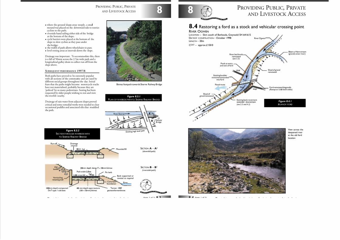
7/27/2019 MAN_mod
http://slidepdf.com/reader/full/manmod 69/84
8
PROVIDING PUBLIC, PRIVATE
AND LIVESTOCK A CCESS
• where the ground slopes away steeply, a smallmound was placed on the downward side to restrictcyclists to the path;
• riverside hand railing either side of the bridgeat the bottom of the slope;
• cycle barriers were placed at the bottom of theslope to slow cyclists as they pass underthe bridge;
• the width of path allows wheelchairs to pass;
• level resting areas at intervals down the slope.
Drainage was important. To accommodate this, thereis a fall of 50mm across the 2.5m wide path and a longitudinal gulley drain to collect run off from theslope above.
SUBSEQUENT PERFORMANCE 1997/8
Both paths have proved to be extremely popular with all sections of the community and are used by different social groups throughout the day. Initialfears that the paths might become motorcycle trackshave not materialised, probably because they are‘policed’ by so many pedestrians. Seating has beenrequested by older people wishing to rest and view the riverlife nearby.
Drainage of rain water from adjacent slopes provedcritical and some remedial works were needed to clearoccassional puddles and associated silts that muddiedthe path.
River SkerneA l b e r t
R o a d A1
B1
B
A
N e wp a t h
E xis ting high le vel pa th
D o w n
toRailwayBridge
40 mm depth open texture(10 – 15mm) bitmac
Pin kerb
River
Bank supported orreveted as required
Mounded fill
20mm depth dense 7 – 10mm bitmac
100mm depth compactedDoT type 1 sub base
Path width 2.5m
Concretefoundation
Vertical logretaining wall
Drainagechannel
Oldlandfill
'Terram 1000'geotextile membrane
1:50 cross fall
Fall
Run-off
Fall
Figure 8.3.2
SECTIONTHROUGH RIVERSIDE RATH
TO SKERNE RAILWAY BRIDGE
Figure 8.3.1
PLAN OF RIVERSIDE PATHTO SKERNE RAILWAY BRIDGE
Bitmac footpath towards Skerne Railway Bridge
SECTION A – A1
(downhill path)
SECTION B – B1
(riversidel path)
PROVIDING PUBLIC, PRIVATE
AND LIVESTOCK A CCESS8
8.4 Restoring a ford as a stock and vehicular crossing pointRIVER OGWENLOCATION – 5km south of Bethesda, Gwynedd SH 641615
DATEOF CONSTRUCTION – October 1998LENGTH – 20m
COST – approx.£150 0
Existing bank revetmentextended downstream(see 5.3 and 4.2)
Existing boulderrevetment extended
into ford
Ford reinstated diagonally(Ramps at 1:10 both sides)Wall
Wall
Flood route
Pool
Pool
Shoal of gravel reinstated
Shoal of gravelreinstated
Blaen-y-Nant stream(gravels enter river)
River Ogwen
31Pools at entry
and exit of ford
River bed levelsreinstated(see 5.3)
Figure 8.4.1
PLANOF FORD
View across thedeepened riverat the old ford
location
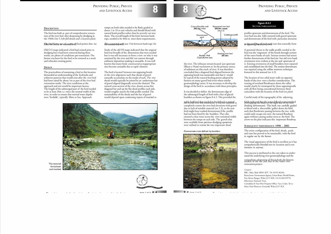
7/27/2019 MAN_mod
http://slidepdf.com/reader/full/manmod 70/84
DESCRIPTION
The ford was built as part of comprehensive restora-tion of the river bed after deepening by dredging inthe 1960s (See 5.3 for full details and a location plan).
The ford forms one of a series of fixed points that sta-bilise the bed at its restored level.
Old O.S maps indicated a ford had existed prior todredging but it had been removed during these
works; see photo of conditions pre-restoration. Thefarmer was keen for the ford to be restored as a stock and vehicular crossing point.
DESIGN
The practicalities of sustaining a ford at this locationdemanded an understanding of the hydraulic andsediment patterns that would exist after the river bedhad been raised by about 1m as part of the river bedrestoration works. The river conditions at theapproach and exit would be important factors.The length of the submerged part of the ford neededto be at least 20m i.e. twice the normal width of theriver, in order to ensure that normal water depths
were ‘fordable’, typically 30cm or less. Approach
ramps on both sides needed to be flatly graded atabout 1 in 10 to suit vehicles and should blend withnatural bank profiles rather than be severely cut intothem. The overall length of the ford, between bank tops, needed to be 40m to meet these requirements.
This compared with just 15m between bank tops forthe natural channel.
Study of the old OS maps indicated that the originalford was broadly of the dimensions that were neededbut it was still necessary to form a view on why it wassustained by the river and did not narrow throughsediment deposition making it unusable. It was wellknown that many fords constructed at inappropriatesites become unusable due to rapid siltation.
The ford is located between two opposing bendsin the river alignment such that shoals of gravelnaturally accumulate on the inside of each. The twoshoals would typically be joined by an underwater barof gravel aligned diagonally across the channel. Thenatural cross-section of the river, drawn across thisdiagonal bar and up the flat shoal profiles each side,
would roughly match the ford profile needed. Thesustainability of the shoals and the bar of gravel
would depend upon continuing inputs of material to
8
PROVIDING PUBLIC, PRIVATE
AND LIVESTOCK A CCESS
The restored
ford,shoalsand riverbed
PROVIDING PUBLIC, PRIVATE
AND LIVESTOCK A CCESS8
the river. The tributary stream located just upstream(Blaen-y-Nant) was known to be the primary sourceof sediment on this reach of river. It was thereforeconcluded that a diagonal ford aligned between theopposing bends was sustainable and that it wouldbe typical of the natural fording points adopted by farmers on many gravel bed rivers where similargeomorphology arises. It was necessary to develop thedesign of the ford in accordance with these principles.
It was decided to define the downstream edge of the submerged length of ford with a line of glacialboulders as shown on figure 8.4.2. This provided the
stable bed level that needed to be defined as part of the overall river bed restoration. It was not possible tocompletely restore the river bed elevations with graveldue to lack of suitable material (see 5.3), so the new ford might have washed downstream if the profilehad not been fixed by the boulders. They alsoensured a clear route across the river remained visiblebetween the ramps on each side. The gravels that
were available from previous dredging operations were utilised to restore the two important shoal
profiles upstream and downstream of the ford. Theriver bed was also fully restored with gravel upstreamand downstream of the ford with particular attention
to the profiling of pools and runs that naturally format opposing bends (see plan).
A potential threat to the stable profile needed at theford was the ‘migration’ of the bends through erosionof the outer banks of each. Serious erosion had arisenfurther downstream of the ford site but old river bank revetments were evident at the site and upstream of it. Existing revetments of small boulders were repairedand consolidated into the ford. The erosion downstream
was repaired using the willow mattress techniquefeatured in this manual (see 4.2 ).
The location of two solid stone walls on oppositebanks of the river were a further consideration. Therouting of overland floodwaters down the valley
would clearly be interrupted by these opposing walls with all flow being concentrated between themcoincident with the location of the ford (see plan).
Careful study of the topography of the adjoining
fields indicated that the natural flood route involvedovertopping the bank on the right side of the ford(looking downstream). This bank was carefully gradedto blend with a discernible ‘gulley’ down the fieldsuch that floodwater passing between the two wallscould easily escape out onto the natural floodway again without causing undue stress at the ford. Thearrow on the plan indicates this important floodway.
SUBSEQUENT PERFORMANCE 1998 – 2001
The entire configuration of the ford, shoals, poolsand runs has proved to be sustainable, with the fordin regular use by the farmer.
The visual appearance of the ford is excellent as it hassympathetically blended into its location and is notintrusive in anyway.
This success is attributed to the care taken to under-stand the underlying river geomorphology and the
sympathetic adaptation of this in both the historiccontext of the site and that of the wider riverrestoration project.
Contacts:
RRC, Silsoe, Beds MK45 4DT, Tel: 01525 863341.
Bryan Jones. Environment Agency, Llwyn Brain, Ffordd Penlan,
Parc Menai, Bangor, Wales LL57 4DE, Tel: 01248 670770.
Elfyn Jones. National Trust,
Carneddau & Ynys Mon Property Office, Tan y Celyn, Ty’n y
Maes, Nant Ffrancon, Gwynedd, Wales LL57 3LX.
Cobble/gravel fill
Boulder Wall(Typically1m size)
Reinstated river bed202.0m mean
(see 5.3)
Exisiting river bed201.0m
Downstreampool
Crest of boulder wall202.2m mean
Figure 8.4.2
SECTION THROUGHFORD
Downstream crest defined by boulders
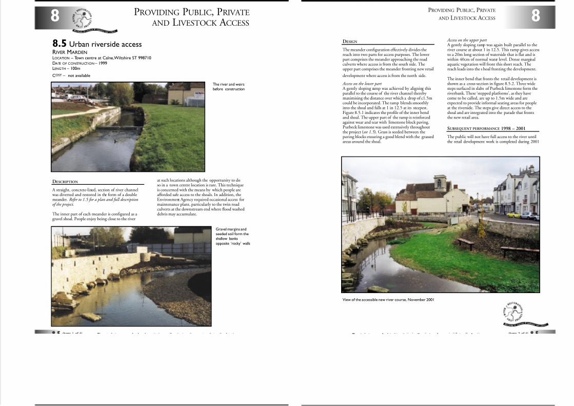
7/27/2019 MAN_mod
http://slidepdf.com/reader/full/manmod 71/84
PROVIDING PUBLIC, PRIVATE
AND LIVESTOCK A CCESS8
8.5 Urban riverside accessRIVER MARDENLOCATION – Town centre at Calne,Wiltshire ST 998710
DATE OF CONSTRUCTION – 1999LENGTH – 100m
COST – not available
DESCRIPTION
A straight, concrete-lined, section of river channel was diverted and restored in the form of a doublemeander. Refer to 1.5 for a plan and full descriptionof the project.
The inner part of each meander is configured as a gravel shoal. People enjoy being close to the river
at such locations although the opportunity to doso in a town centre location is rare. This techniqueis concerned with the means by which people areafforded safe access to the shoals. In addition, theEnvironment Agency required occasional access formaintenance plant, particularly to the twin roadculverts at the downstream end where flood washeddebris may accumulate.
Gravel margins andseeded soil form theshallow banks
opposite ‘rocky’ walls
The river and weirsbefore construction
DESIGN
The meander configuration effectively divides thereach into two parts for access purposes. The lowerpart comprises the meander approaching the roadculverts where access is from the south side. Theupper part comprises the meander fronting new retail
development where access is from the north side.
Access on the lower part A gently sloping ramp was achieved by aligning thisparallel to the course of the river channel thereby maximising the distance over which a drop of c1.5mcould be incorporated. The ramp blends smoothly into the shoal and falls at 1 in 12.5 at its steepest.Figure 8.5.1 indicates the profile of the inner bendand shoal. The upper part of the ramp is reinforcedagainst wear and tear with limestone block paving.Purbeck limestone was used extensively throughoutthe project (see 1.5 ). Grass is seeded between thepaving blocks ensuring a good blend with the grassedareas around the shoal.
Access on the upper part A gently sloping ramp was again built parallel to theriver course at about 1 in 12.5. This ramp gives accessto a 20m long section of waterside that is flat and is
within 40cm of normal water level. Dense marginalaquatic vegetation will front this short reach. Thereach leads into the s hoal fronting the development.
The inner bend that fronts the retail development isshown as a cross-section in figure 8.5.2. Three widesteps surfaced in slabs of Purbeck limestone form theriverbank. These ‘stepped platforms’, as they havecome to be called, are up to 1.5m wide and areexpected to provide informal seating areas for peopleat the riverside. The steps give direct access to theshoal and are integrated into the parade that frontsthe new retail area.
SUBSEQUENT PERFORMANCE 1998 – 2001
The public will not have full access to the river untilthe retail development work is completed during 2001
8
PROVIDING PUBLIC, PRIVATE
AND LIVESTOCK A CCESS
View of the accessible new river course, November 2001
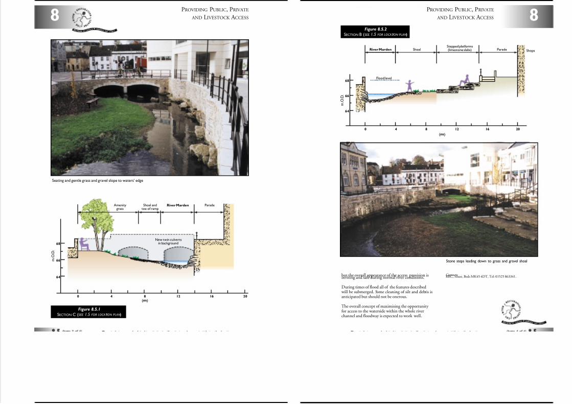
7/27/2019 MAN_mod
http://slidepdf.com/reader/full/manmod 72/84
PROVIDING PUBLIC, PRIVATE
AND LIVESTOCK A CCESS8
Seating and gentle grass and gravel slope to waters’ edge
0 4 8 12 16 20
(m)
64
68
66
Parade
m . O . D .
Shoal andtoe of ramp
New twin culvertsin background
River MardenAmenitygrass
Figure 8.5.1
SECTION C (SEE 1.5 FOR LOCATION PLAN)
8
PROVIDING PUBLIC, PRIVATE
AND LIVESTOCK A CCESS
but the overall appearance of the access provision isinviting and safe during normal river conditions.
During times of flood all of the features described will be submerged. Some cleaning of silt and debris isanticipated but should not be onerous.
The overall concept of maximising the opportunity for access to the waterside within the whole riverchannel and floodway is expected to work well.
Contacts:RRC, Silsoe, Beds MK45 4DT, Tel: 01525 863341.
Stone steps leading down to grass and gravel shoal
0 4 8 12 16 20
(m)
64
68
66
Parade Shops
Flood level
m . O . D .
ShoalStepped platforms(limestone slabs)River Marden
Figure 8.5.2
SECTION B (SEE 1.5 FOR LOCATION PLAN)
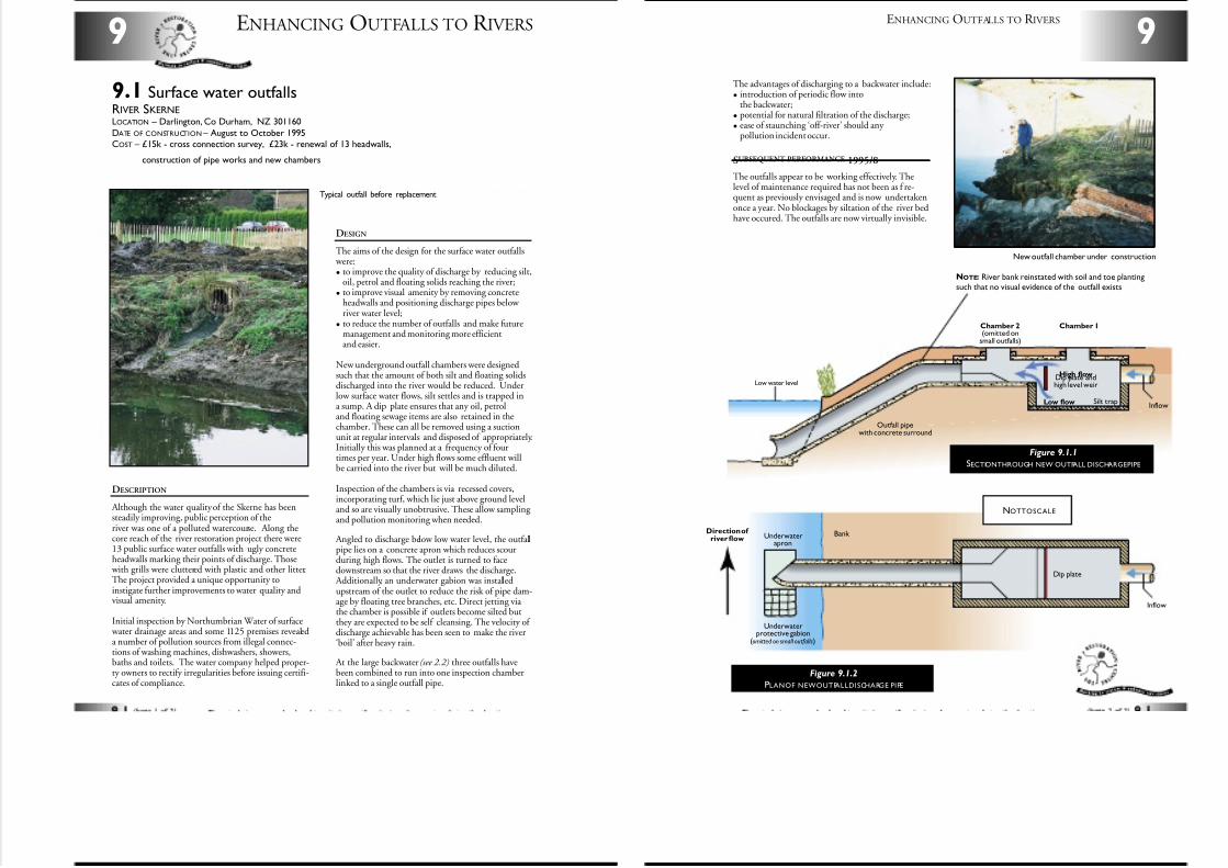
7/27/2019 MAN_mod
http://slidepdf.com/reader/full/manmod 73/84
DESCRIPTION
Although the water quality of the Skerne has beensteadily improving, public perception of theriver was one of a polluted watercourse. Along thecore reach of the river restoration project there were13 public surface water outfalls with ugly concreteheadwalls marking their points of discharge. Those
with grills were cluttered with plastic and other litter.The project provided a unique opportunity toinstigate further improvements to water quality andvisual amenity.
Initial inspection by Northumbrian Water of surface water drainage areas and some 1125 premises revealeda number of pollution sources from illegal connec-tions of washing machines, dishwashers, showers,baths and toilets. The water company helped proper-ty owners to rectify irregularities before issuing certifi-cates of compliance.
ENHANCING OUTFALLS TO R IVERS9
9.1 Surface water outfallsRIVER SKERNELOCATION – Darlington, Co Durham, NZ 301160
DATE OF CONSTRUCTION – August to October 1995COST – £15k - cross connection survey, £23k - renewal of 13 headwalls,
– construction of pipe works and new chambers
Typical outfall before replacement
DESIGN
The aims of the design for the surface water outfalls were:
• to improve the quality of discharge by reducing silt,oil, petrol and floating solids reaching the river;
• to improve visual amenity by removing concreteheadwalls and positioning discharge pipes below river water level;
• to reduce the number of outfalls and make futuremanagement and monitoring more efficientand easier.
New underground outfall chambers were designedsuch that the amount of both silt and floating solidsdischarged into the river would be reduced. Underlow surface water flows, silt settles and is trapped ina sump. A dip plate ensures that any oil, petroland floating sewage items are also retained in thechamber. These can all be removed using a suctionunit at regular intervals and disposed of appropriately.Initially this was planned at a frequency of fourtimes per year. Under high flows some effluent willbe carried into the river but will be much diluted.
Inspection of the chambers is via recessed covers,incorporating turf, which lie just above ground leveland so are visually unobtrusive. These allow sampling and pollution monitoring when needed.
Angled to discharge below low water level, the outfallpipe lies on a concrete apron which reduces scourduring high flows. The outlet is turned to facedownstream so that the river draws the discharge.
Additionally, an underwater gabion was installedupstream of the outlet to reduce the risk of pipe dam-age by floating tree branches, etc. Direct jetting via the chamber is possible if outlets become silted butthey are expected to be self cleansing. The velocity of discharge achievable has been seen to make the river‘boil’ after heavy rain.
At the large backwater (see 2.2) three outfalls havebeen combined to run into one inspection chamberlinked to a single outfall pipe.
Low water level
Underwaterapron
Bank Direction of river flow
Dip plate
Inflow
Inflow
Dip plate andhigh level weir
Underwaterprotective gabion
(omitted on small outfalls)
Low flow
Outfall pipewith concrete surround
Silt trap
High flow
Chamber 1Chamber 2(omitted on
small outfalls)
The advantages of discharging to a backwater include:
• introduction of periodic flow intothe backwater;
• potential for natural filtration of the discharge;
• ease of staunching ‘off-river’ should any pollution incident occur.
SUBSEQUENT PERFORMANCE 1995/8
The outfalls appear to be working effectively. Thelevel of maintenance required has not been as f re-quent as previously envisaged and is now undertakenonce a year. No blockages by siltation of the river bedhave occured. The outfalls are now virtually invisible.
9
ENHANCING OUTFALLS TO R IVERS
Figure 9.1.2
PLANOF NEWOUTFALLDISCHARGE PIPE
Figure 9.1.1
SECTIONTHROUGH NEW OUTFALL DISCHARGEPIPE
New outfall chamber under construction
NOTE: River bank reinstated with soil and toe plantingsuch that no visual evidence of the outfall exists
NOTTOSCALE
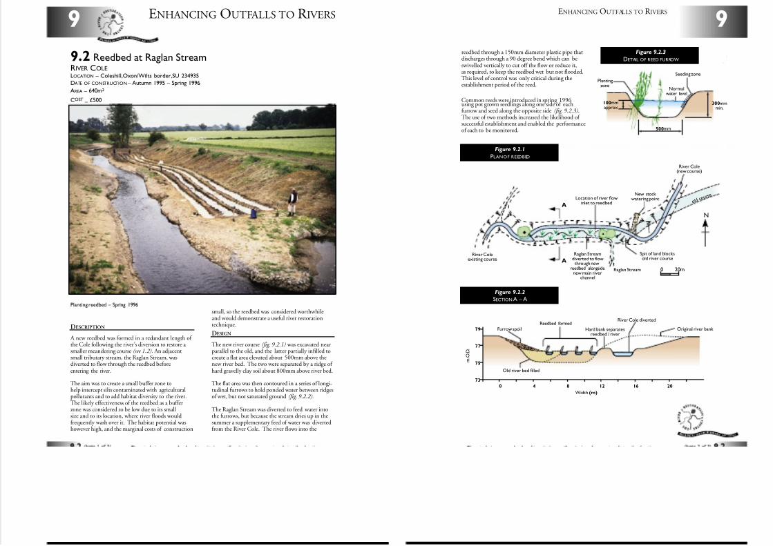
7/27/2019 MAN_mod
http://slidepdf.com/reader/full/manmod 74/84
DESCRIPTION
A new reedbed was formed in a redundant length of the Cole following the river’s diversion to restore a smaller meandering course (see 1.2). An adjacentsmall tributary stream, the Raglan Stream, wasdiverted to flow through the reedbed beforeentering the river.
The aim was to create a small buffer zone tohelp intercept silts contaminated with agriculturalpollutants and to add habitat diversity to the river.The likely effectiveness of the reedbed as a bufferzone was considered to be low due to its smallsize and to its location, where river floods wouldfrequently wash over it. The habitat potential washowever high, and the marginal costs of construction
ENHANCING OUTFALLS TO R IVERS9
9.2 Reedbed at Raglan StreamRIVER COLELOCATION – Coleshill,Oxon/Wilts border,SU 234935
DATE OF CONSTRUCTION – Autumn 1995 – Spring 1996
AREA – 640m2
COST–
£500
Planting reedbed – Spring 1996
small, so the reedbed was considered worthwhileand would demonstrate a useful river restorationtechnique.
DESIGN
The new river course (fig. 9.2.1) was excavated nearparallel to the old, and the latter partially infilled tocreate a flat area elevated about 500mm above thenew river bed. The two were separated by a ridge of hard gravelly clay soil about 800mm above river bed.
The flat area was then contoured in a series of longi-tudinal furrows to hold ponded water between ridgesof wet, but not saturated ground (fig. 9.2.2).
The Raglan Stream was diverted to feed water intothe furrows, but because the stream dries up in thesummer a supplementary feed of water was divertedfrom the River Cole. The river flows into the
9
ENHANCING OUTFALLS TO R IVERS
A
A
N
River Coleexisting course
Raglan Streamdiverted to flowthrough new
reedbed alongsidenew main river
channel
Raglan Stream 0 20m
Spit of land blocksold river course
o l dc o u
r s eNew stock
watering pointLocation of river flowinlet to reedbed
River Cole(new course)
Figure 9.2.1
PLANOF REEDBED
73
0 4 8 12 16 20
75
77
79
Reedbed formed
Hard bank separatesreedbed / river
Old river bed filled
River Cole diverted
Furrow spoil Original river bank
m . O . D .
Width (m)
Figure 9.2.2
SECTION A – A
reedbed through a 150mm diameter plastic pipe thatdischarges through a 90 degree bend which can beswivelled vertically to cut off the flow or reduce it,as required, to keep the reedbed wet but not flooded.This level of control was only critical during theestablishment period of the reed.
Common reeds were introduced in spring 1996using pot grown seedlings along one side of eachfurrow and seed along the opposite side (fig. 9.2.3).The use of two methods increased the likelihood of successful establishment and enabled the performanceof each to be monitored.
Seeding zone
Normalwater level
Plantingzone
100mmapprox
500mm
300mmmin.
Figure 9.2.3
DETAIL OF REED FURROW
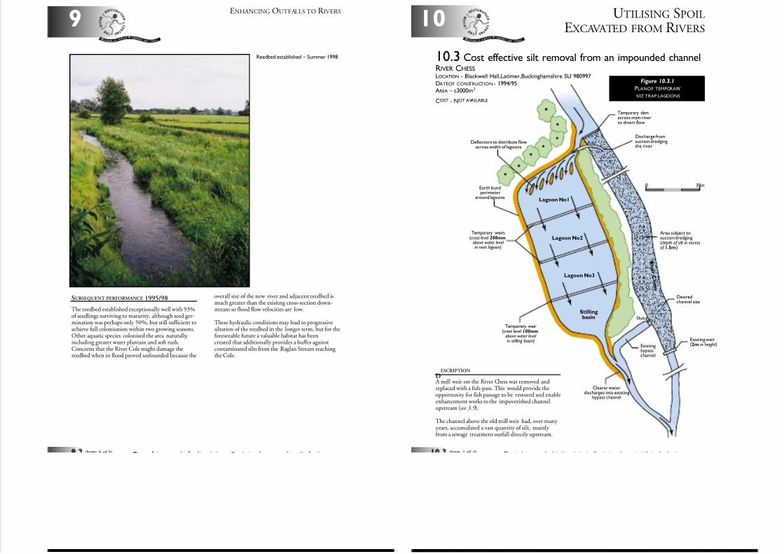
7/27/2019 MAN_mod
http://slidepdf.com/reader/full/manmod 75/84
ENHANCING OUTFALLS TO R IVERS
9
SUBSEQUENT PERFORMANCE 1995/98
The reedbed established exceptionally well with 93%of seedlings surviving to maturity, although seed ger-mination was perhaps only 50%, but still sufficient toachieve full colonisation within two growing seasons.Other aquatic species colonised the area naturally,including greater water plantain and soft rush.Concerns that the River Cole might damage thereedbed when in flood proved unfounded because the
Reedbed established – Summer 1998
overall size of the new river and adjacent reedbed ismuch greater than the exisitng cross-section down-stream so flood flow velocities are low.
These hydraulic conditions may lead to progressivesiltation of the reedbed in the longer term, but for theforeseeable future a valuable habitat has beencreated that additionally provides a buffer againstcontaminated silts from the Raglan Stream reaching the Cole.
0 30m
Temporary weirs(crest level 200mm
above water level in next lagoon)
Earth bundperimeter
around lagoons
Discharge fromsuction dredgingthe river
Area subject tosuction dredging(depth of silt in excessof 1.5m)
Lagoon No1
Lagoon No2
Lagoon No3
R i v e r C
h e s s
Stillingbasin
Existing weir(2m in height)
Desiredchannel size
Existingbypasschannel
Sluice
Temporary damacross main riverto divert flow
Deflectors to distribute flowacross width of lagoons
Temporary weir(crest level 100mm
above water level in stilling basin)
Clearer waterdischarges into existing
bypass channel
UTILISING SPOIL
E XCAVATED FROM R IVERS10
DESCRIPTION
A mill weir on the River Chess was removed andreplaced with a fish-pass. This would provide theopportunity for fish passage to be restored and enableenhancement works to the impoverished channelupstream (see 3.9 ).
The channel above the old mill weir had, over many years, accumulated a vast quantity of silt, mainly from a sewage treatment outfall directly upstream.
10.3 Cost effective silt removal from an impounded channelRIVER CHESSLOCATION - Blackwell Hall,Latimer,Buckinghamshire SU 980997
DATEOF CONSTRUCTION - 1994/95AREA – c3000m2
COST - NOT AVAILABLE
Figure 10.3.1
PLANOF TEMPORARY
SILT TRAP LAGOONS
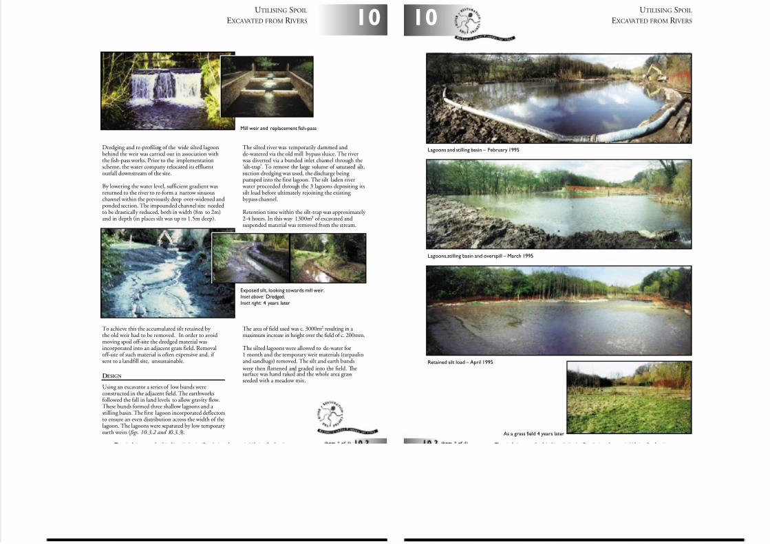
7/27/2019 MAN_mod
http://slidepdf.com/reader/full/manmod 76/84
Dredging and re-profiling of the wide silted lagoonbehind the weir was carried out in association withthe fish-pass works. Prior to the implementationscheme, the water company relocated its effluentoutfall downstream of the site.
By lowering the water level, sufficient gradient wasreturned to the river to re-form a narrow sinuouschannel within the previously deep over-widened andponded section. The impounded channel size neededto be drastically reduced, both in width (8m to 2m)and in depth (in places silt was up to 1.5m deep).
To achieve this the accumulated silt retained by the old weir had to be removed. In order to avoidmoving spoil off-site the dredged material wasincorporated into an adjacent grass field. Removaloff-site of such material is often expensive and, if sent to a landfill site, unsustainable.
DESIGN
Using an excavator a series of low bunds wereconstructed in the adjacent field. The earthworksfollowed the fall in land levels to allow gravity flow.These bunds formed three shallow lagoons and a stilling basin. The first lagoon incorporated deflectorsto ensure an even distribution across the width of thelagoon. The lagoons were separated by low temporary earth weirs ( figs. 10.3.2 and 10.3.3).
The silted river was temporarily dammed andde-watered via the old mill bypass sluice. The river
was diverted via a bunded inlet channel through the‘silt-trap’. To remove the large volume of saturated silt,suction dredging was used, the discharge being pumped into the first lagoon. The silt laden river
water proceeded through the 3 lagoons depositing itssilt load before ultimately rejoining the existing bypass channel.
Retention time within the silt-trap was approximately 2-4 hours. In this way 1300m3 of excavated andsuspended material was removed from the stream.
The area of field used was c. 3000m2 resulting in a maximum increase in height over the field of c. 200mm.
The silted lagoons were allowed to de-water for1 month and the temporary weir materials (tarpaulinand sandbags) removed. The silt and earth bunds
were then flattened and graded into the field. Thesurface was hand raked and the whole area grassseeded with a meadow mix.
Exposed silt, looking towards mill weir.Inset above: Dredged.Inset right: 4 years later
10
UTILISING SPOIL
E XCAVATED FROM R IVERS
Mill weir and replacement fish-pass
UTILISING SPOIL
E XCAVATED FROM R IVERS10
Lagoons and stilling basin – February 1995
Lagoons,stilling basin and overspill – March 1995
Retained silt load – April 1995
As a grass field 4 years later
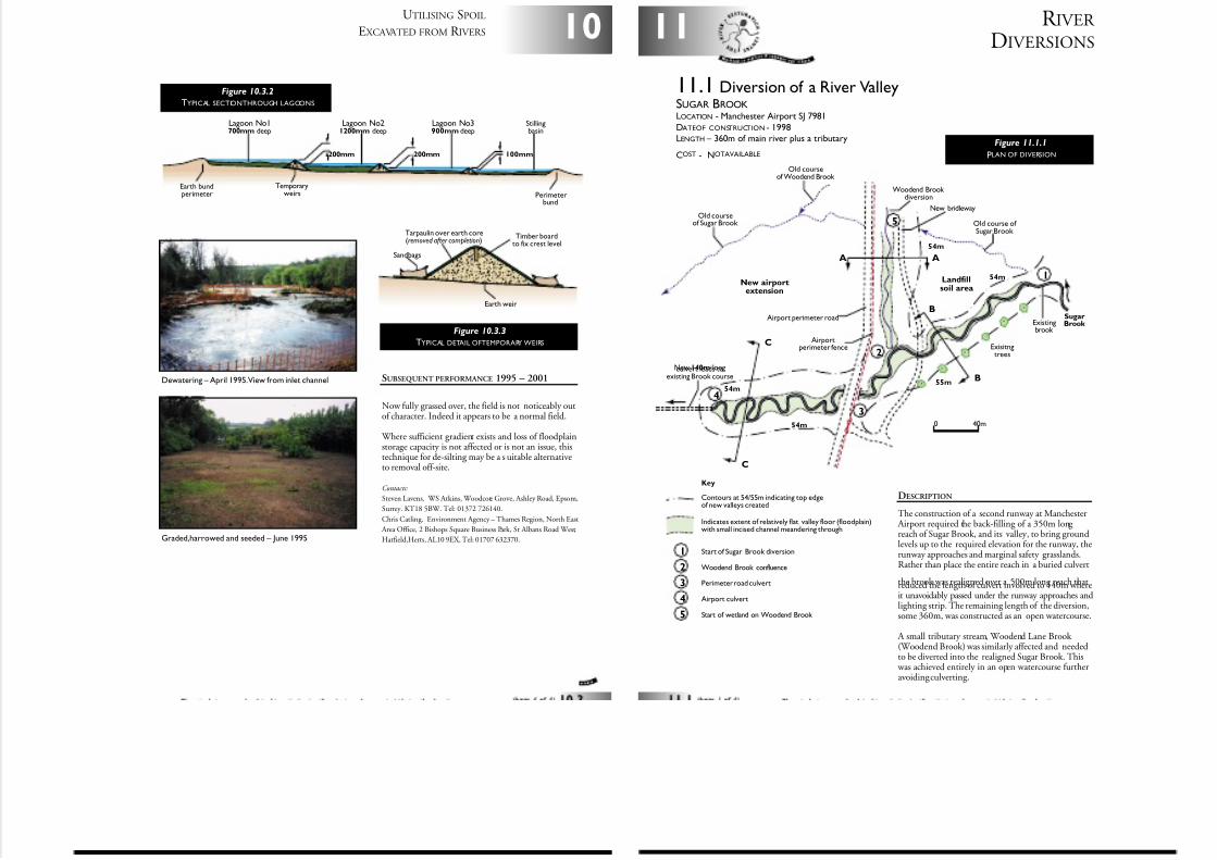
7/27/2019 MAN_mod
http://slidepdf.com/reader/full/manmod 77/84
10
UTILISING SPOIL
E XCAVATED FROM R IVERS
SUBSEQUENT PERFORMANCE 1995 – 2001
Now fully grassed over, the field is not noticeably outof character. Indeed it appears to be a normal field.
Where sufficient gradient exists and loss of floodplainstorage capacity is not affected or is not an issue, thistechnique for de-silting may be a s uitable alternativeto removal off-site.
Contacts:
Steven Lavens. WS Atkins, Woodcote Grove, Ashley Road, Epsom,
Surrey. KT18 5BW. Tel: 01372 726140.
Chris Catling. Environment Agency – Thames Region, North East
Area Office, 2 Bishops Square Business Park, St Albans Road West,
Hatfield,Herts, AL10 9EX, Tel: 01707 632370.Graded,harrowed and seeded – June 1995
Dewatering – April 1995.View from inlet channel
Perimeterbund
Earth bundperimeter
200mm 100mm200mm
Lagoon No1700mm deep
Lagoon No21200mm deep
Lagoon No3900mm deep
Stillingbasin
Temporaryweirs
Figure 10.3.2
TYPICAL SECTIONTHROUGH LAGOONS
Earth weir
Sandbags
Timber boardto fix crest level
Tarpaulin over earth core(removed after completion)
Figure 10.3.3
TYPICAL DETAIL OFTEMPORARY WEIRS
R IVER
DIVERSIONS11
DESCRIPTION
The construction of a second runway at Manchester Airport required the back-filling of a 350m long reach of Sugar Brook, and its valley, to bring groundlevels up to the required elevation for the runway, therunway approaches and marginal safety grasslands.Rather than place the entire reach in a buried culvert
the brook was realigned over a 500m long reach thatreduced the length of culvert involved to 140m whereit unavoidably passed under the runway approaches andlighting strip. The remaining length of the diversion,some 360m, was constructed as an open watercourse.
A small tributary stream, Woodend Lane Brook (Woodend Brook) was similarly affected and neededto be diverted into the realigned Sugar Brook. This
was achieved entirely in an open watercourse furtheravoiding culverting.
11.1 Diversion of a River ValleySUGAR BROOKLOCATION - Manchester Airport SJ 7981
DATEOF CONSTRUCTION - 1998LENGTH – 360m of main river plus a tributary
COST - NOTAVAILABLE
0 40m
Old courseof Sugar Brook
New 140m longculvert leads toexisting Brook course
Old courseof Woodend Brook
Woodend Brook diversion
New bridleway
Landfillsoil area
New airportextension
Old course of Sugar Brook
Exisitngtrees
Airport perimeter road
Airportperimeter fence
Existingbrook
Key
Contours at 54/55m indicating top edgeof new valleys created
Indicates extent of relatively flat valley floor (floodplain)with small incised channel meandering through
Start of Sugar Brook diversion
Woodend Brook confluence
Perimeter road culvert
Airport culvert
Start of wetland on Woodend Brook
A A
B
B
C
C
54m
54m
55m
54m
Sugar Brook
54m
4
3
2
1
2
3
4
5
5
1
Figure 11.1.1
PLAN OF DIVERSION
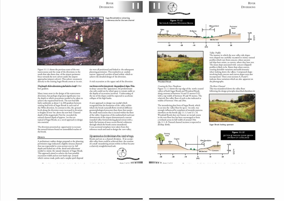
7/27/2019 MAN_mod
http://slidepdf.com/reader/full/manmod 78/84
Figure 11.1.1 shows the previous route of the two watercourses and the route of the diversions to thesouth that take them clear of the airport perimeterfence towards the new culvert under the airportapproaches (airport culvert). This culvert reconnectsdirectly to the existing Sugar Brook course at its exit.
The length of the diversion equalled the length thatit replaced, thus maintaining the same overallbed gradient.
Many issues arose in the design of the watercoursediversions, but perhaps of greatest significance wasthe depth to which excavations needed to be taken toachieve the required bed levels. The new bed fallsfairly uniformly at about 1 in 200 gradient betweenexisting bed levels of Sugar Brook at each end of the 500m diversion. In contrast to this, the groundlevels along the diversion route increased in elevationto heights of over 5m above the new bed. Channeldepth of this magnitude (5m) far exceeded thenatural channel depth of approx. 1m that aretypical of Sugar Brook, so a novel approach to design
was essential.
The diversion presented an opportunity to recreatethe natural features found on unmodified reaches of the brook.
DESIGN
A preliminary outline design prepared at the planning permission stage indicated a slightly sinuous channelthat was trapezoidal in cross-section over its fulldepth and lacked any of the detail and refinementneeded to mimic the natural character of Sugar Brook.This approach aimed to acheive the least possibleexcavation width and set new bank tops around
which various roads, paths and a surplus spoil disposal
site were all positioned and linked to the subsequentplanning permission. This resulted in an unduly narrow ‘approved’ corridor of land within which toachieve the detailed design of the diversion.
A trial excavation at the upper end of the diversion
reach was undertaken to test the outline design. This was shown to be completely inappropiate. Apart fromits deep ‘canyon-like’ appearance, the predominantclay soils could not be relied upon to remain stable atthe depths of excavation involved. Undercutting of the toe of the slopes could be expected to acceleratecollapse of the high banks.
A new approach to design was needed whichrecognised that the formation of the valley within
which the brook naturally flows involved differentgeomorphological processes than those that sustainthe small watercourse that is incised within the floorof the valley. Inspection of the undisturbed reach justdownstream of the airport demonstrated a narrow rounded valley formed during glacial retreat with a fairly flat bottom of more recent fluvial s edimentsthrough which the brook course meandered.Cross-sectional templates were taken from thisreference reach and used to design the new valley.
The approach to detailed design thus involved treat-ing the diversion as a diversion of the valley of SugarBrook and not as a channel diversion. If an accept-able valley form could be achieved then the creationof a small meandering stream within its floor becamea relatively straightforward task.
11
R IVER
DIVERSIONS
Sugar Brook before culverting,a reference site for the new channel
50
-30 -20 -10 0 10
55
20(m)
Fill15m floodplain
Convex
Existingtrees
Concave
55m
50.3m bed
m . O .D .
R IVER
DIVERSIONS11
Creating the New Planforms Figure 11.1.1 shows the top edge of the newly createdvalleys of both Sugar Brook and Woodend Brook along contours of between 54 and 55 metres O.D.
with a top width of between 30 and 50 metres. Therelatively flat valley floor of each is also indicated at
widths of between 10m and 20m.
The meandering plan form of Sugar Brook, whichis cut into the valley floor by up to 1m only, wasstrongly influenced by templates of meander patternselsewhere on the brook ( figs 11.1.3 and 11.1.4 ).
Woodend Brook does not feature an incised coursein the new floor but has been encouraged to forma wetland across its full width of around 10m( fig 11.1.2 ). Natural channel incision is expected todevelop slowly.
Valley Profiles The manner in which the new valley side slopes
were shaped was carefully excavated to mimic naturalprofiles which vary from concave, where ancientsoil slips have arisen, to convex, where they have not.The mean slope associated with concave (slipped)profiles is likely to be flatter than when convex,creating desirable variations and mild sinuosity
when looking down the valleys. Compound slopesinvolving both concave and convex slopes were alsoincorporated. Three cross-sections A, B and Cindicate these variations which are also apparent onthe photographs.
The River Channel This was meandered down the valley floorfollowing the design principles described elsewhere in
Figure 11.1.3
SECTION B THROUGH SUGAR BROOK
UPSTREAM OF CONFLUENCE
Woodend Brook
Sugar Brook looking upstream
50
-30 -20 -10 0 10 20
55
(m)
Perimeterfence
RoadFill
10m wetland
Bridleway54m
1: 10 1 : 4
50.7m bed
m . O .D .
Figure 11.1.2
SECTION A THROUGH WOODEND BROOK
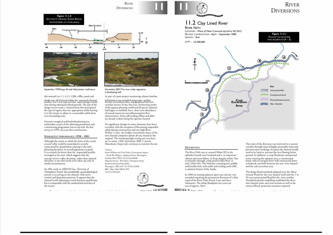
7/27/2019 MAN_mod
http://slidepdf.com/reader/full/manmod 79/84
this manual (see 1.1, 6.2.). Cliffs, riffles, pools and
shoals were all initiated within the excavated channelprofiles, but it was expected that rapid changes wouldarise during subsequent flood periods. The aim of thedesign was to create a channel form that anticipatedthe type of regime that was appropriate whilst leaving it to the stream to adjust to a reasonably stable formover succeeding years.
Extensive marginal and bankside planting wasundertaken as part of the planning permission anda monitoring programme was set up with the firstsurvey in 1999, one year after construction.
SUBSEQUENT PERFORMANCE 1998 – 2001
Although the extent to which the form of the newly created valley could be naturalised is severely constrained by spatial limits relating to the early planning decisions, its overall appearance is good.It is certainly far better than the trapezoidal profilesenvisaged at the start, which suggests that the
concept of river valley diversion, rather than channeldiversion, is one that needs to be taken up early insimilar circumstances.
An MSc study in 2000 ( M Guy, University of Nottingham) found that considerable geomorphologicalactivity is occurring on the channel, with activeerosion and deposition patterns. It appears that thechannel is still adjusting to reach dynamic equilibriumbut is comparable with the undisturbed stretches of the stream.
As part of a post project monitoring scheme baseline
information was compiled using water quality,benthic invertebrate data, topographical and rivercorridor surveys. In the first year, monitoring resultsof the aquatic planting confirmed all species plantedhad begun to establish, but a short term abundanceof annual watercress was influencing low flow characteristics. Some self-seeding willow and alderare already evident along the riparian channel.
No significant changes in water chemistry have beenrecorded, with the exception of fluctuating suspendedsolids during construction and very high flows.
Within 2 years, the benthic invertebrate fauna of thenew channel comprises almost all taxa found in theoriginal. The remaining high scoring rare taxa haveyet to return. ( MSc dissertation 2001 Z. James ).Manchester Airport plc continues to monitor the site.
Contacts:
Karen Williams and Pam Nolan, Environment Agency
– North West Region, Appleton House, Warrington,
Cheshire WA3 7WD, Tel: 01925 840000
Malcolm Hewitt. WS Atkins, Thompson House,
Birchwood Science Park, Risley,
Warrington. WA3 6AT, Tel: 01925 622000
RRC, Silsoe, Beds MK45 4DT,
Tel: 01525 863341.
11
R IVER
DIVERSIONS
50
-40 -30 -20 -10 0 10
55
20(m)
20m floodplain
54m
49.0m bed
m
. O .D .
Compound slope
ConcaveCliff
Figure 11.1.4
SECTION C THROUGH SUGAR BROOK
DOWNSTREAM OF CONFLUENCE
September 1999.Sugar Brook Valley below confluence November 2001.The river valley vegetationis developing well
R IVER
DIVERSIONS11
11.2 Clay Lined RiverRIVER NITHLOCATION - West of New Cumnock,Ayrshire NS 5412
DATEOF CONSTRUCTION - April – September 2000LENGTH – 3km
COST - £3,300,000
Figure 11.2.1
PLANOF KEYFEATURES
AND SEQUENCES (A – E)
DESCRIPTION
The River Nith rises at around 500m OD in theuplands of south-west Scotland and is an important
salmon and trout fishery. It drops sharply within 7kmto meander through a wide grazed valley floor atonly 220m OD. The Nith has a mixed gravel, pebbleand boulder bed, with stable and eroding earth cliffs,a common feature of the banks.
In 2000 an existing adjacent open-cast coal site wasextended requiring the permanent diversion of a 3kmreach of the River Nith, Beoch Lane and threetributaries. The whole floodplain site covers anarea of approx. 3km2.
The route of the diversion was restricted to a narrow corridor through areas of highly permeable strata andprevious mine workings. In places the channel wouldneed to be lined to prevent the river flowing below ground. In addition, to stop floodwater and ground
water entering the opencast area, a containmentbund, with an integral slurry wall constructed downto bedrock, was built between the new river channeland the coal excavation area.
The design flood standards adopted were the Mean Annual Flood for the river channel itself and the 1 in50 year return period flood for the river corridor.Detailed hydraulic modelling established the diver-sion channel route and cross sections as well as theextent of flood protection measures required.
0 500m
N
Beoch Lane CoalExcavation
Area
Key
Untouched Nith
Containment bund
Diverted watercourses
New diversion
E
D
C
B
A
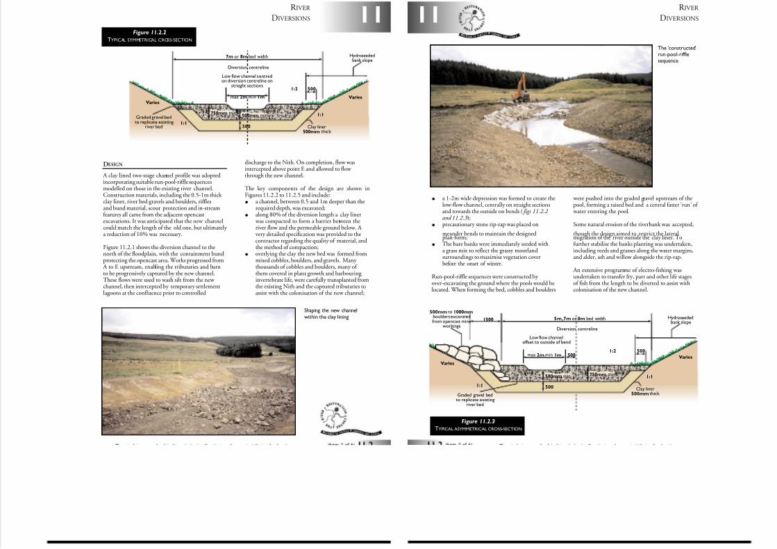
7/27/2019 MAN_mod
http://slidepdf.com/reader/full/manmod 80/84
11
R IVER
DIVERSIONS
DESIGN
A clay lined two-stage channel profile was adoptedincorporating suitable run-pool-riffle sequencesmodelled on those in the existing river channel.Construction materials, including the 0.5-1m thick clay liner, river bed gravels and boulders, rifflesand bund material, scour protection and in-streamfeatures all came from the adjacent opencastexcavations. It was anticipated that the new channelcould match the length of the old one, but ultimately a reduction of 10% was necessary.
Figure 11.2.1 shows the diversion channel to thenorth of the floodplain, with the containment bundprotecting the opencast area. Works progressed from
A to E upstream, enabling the tributaries and burnto be progressively captured by the new channel.These flows were used to wash silt from the new channel, then intercepted by temporary settlementlagoons at the confluence prior to controlled
discharge to the Nith. On completion, flow wasintercepted above point E and allowed to flow through the new channel.
The key components of the design are shown inFigures 11.2.2 to 11.2.5 and include:
• a channel, between 0.5 and 1m deeper than therequired depth, was excavated;
• along 80% of the diversion length a clay liner was compacted to form a barrier between theriver flow and the permeable ground below. A very detailed specification was provided to thecontractor regarding the quality of material, andthe method of compaction;
• overlying the clay the new bed was formed frommixed cobbles, boulders, and gravels. Many thousands of cobbles and boulders, many of them covered in plant growth and harbouring invertebrate life, were carefully transplanted fromthe existing Nith and the captured tributaries toassist with the colonisation of the new channel;
max 2m,min 1m
7m or 8m bed width
500
500
500mm min750mm min
Low flow channel centredon diversion centreline on
straight sections
Graded gravel bedto replicate existing
river bed
VariesVaries
1:1
1:1
1:2
Hydroseededbank slope
Clay liner500mm thick
Diversion centreline
Figure 11.2.2
TYPICAL SYMMETRICAL CROSS-SECTION
Shaping the new channel
within the clay lining
R IVER
DIVERSIONS11
• a 1-2m wide depression was formed to create thelow-flow channel, centrally on straight sectionsand towards the outside on bends ( figs 11.2.2 and 11.2.3);
• precautionary stone rip-rap was placed on
meander bends to maintain the designedplan-form;
• The bare banks were immediately seeded witha grass mix to reflect the grassy moorlandsurroundings to maximise vegetation coverbefore the onset of winter.
Run-pool-riffle sequences were constructed by over-excavating the ground where the pools would belocated. When forming the bed, cobbles and boulders
were pushed into the graded gravel upstream of thepool, forming a raised bed and a central faster ‘run’ of
water entering the pool.
Some natural erosion of the riverbank was accepted,
though the design aimed to restrict the lateralmigration of the river outside the clay liner. Tofurther stabilise the banks planting was undertaken,including reeds and grasses along the water margins,and alder, ash and willow alongside the rip-rap.
An extensive programme of electro-fishing wasundertaken to transfer fry, parr and other life stagesof fish from the length to be diverted to assist withcolonisation of the new channel.
Figure 11.2.3
TYPICAL ASYMMETRICAL CROSS-SECTION
max 2m,min 1m 500
5m,7m or 8m bed width1500
500
500
500mm min 750mm min
Low flow channeloffset to outside of bend
Varies
Varies
1:1
1:1
1:2
500mm to 1000mmboulders excavatedfrom opencast mine
workings
Hydroseededbank slope
Clay liner500mm thick
Diversion centreline
Graded gravel bedto replicate existing
river bed
The ‘constructed’run-pool-rifflesequence
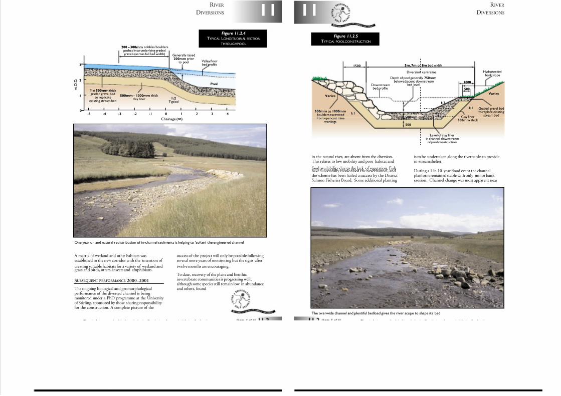
7/27/2019 MAN_mod
http://slidepdf.com/reader/full/manmod 81/84
A matrix of wetland and other habitats wasestablished in the new corridor with the intention of
creating suitable habitats for a variety of wetland andgrassland birds, otters, insects and amphibians.
SUBSEQUENT PERFORMANCE 2000–2001
The ongoing biological and geomorphologicalperformance of the diverted channel is being monitored under a PhD programme at the University of Stirling, sponsored by those sharing responsibility for the construction. A complete picture of the
success of the project will only be possible following several more years of monitoring but the signs after
twelve months are encouraging.
To date, recovery of the plant and benthicinvertebrate communities is progressing well,although some species still remain low in abundanceand others, found
11
R IVER
DIVERSIONS
200 – 300mm cobbles/boulderspushed into underlying gradedgravels (across full bed width)
Min 500mm thick graded gravel bed
to replicateexisting stream bed
Pool
1:2Typical
Generally raised200mm prior
to pool Valley floorbed profile
500mm – 1000mm thick clay liner
0
1
2
3
0-1-2-3-4 4321-5
Chainage (m)
m . O . D .
Figure 11.2.4
TYPICAL LONGITUDINAL SECTION
THROUGHPOOL
One year on and natural redistribution of in-channel sediments is helping to ‘soften’ the engineered channel
R IVER
DIVERSIONS11
in the natural river, are absent from the diversion.This relates to low mobility and poor habitat and
food availability due to the lack of vegetation. Fishhave successfully recolonised the new channel, andthe scheme has been hailed a success by the DistrictSalmon Fisheries Board. Some additional planting
is to be undertaken along the riverbanks to providein-stream shelter.
During a 1 in 10 year flood event the channelplanform remained stable with only minor bank erosion. Channel change was most apparent near
5m,7m or 8m bed width1500
1000
500
500
500mm min
Diversion centreline
Downstreambed profile
VariesVaries
1:1
1:1
1:2
500mm to 1000mmboulders excavatedfrom opencast mine
workings
Depth of pool generally 750mmbelow adjacent downstream
bed level
Level of clay linerin channel downstreamof pool construction
Graded gravel bedto replace existing
stream bed
Hydroseededbank slope
Clay liner500mm thick
Figure 11.2.5
TYPICAL POOLCONSTRUCTION
The overwide channel and plentiful bedload gives the river scope to shape its bed
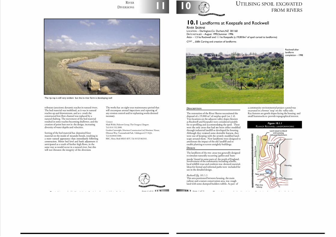
7/27/2019 MAN_mod
http://slidepdf.com/reader/full/manmod 82/84
tributary junctions; dynamic reaches in natural rivers.The bed material was mobilised, as it was in naturalreaches up and downstream, and as a result theconstructed low-flow channel was replaced by a natural thalweg. The movement of the bed materialresulted in some reaches becoming shallower, and thecreation of point bars not in the design, increasing diversity of water depths and velocities.
Sorting of the bed material has deposited finermaterial on the inside of meander bends, resulting ina more natural appearance than immediately following construction. Minor bed level and bank adjustment isanticipated as a result of further high flows, in thesame way as would occur in a natural river, but this
will not threaten the integrity of the diversion.
The works has an eight-year maintenance period that will encompass annual inspections and reporting of any erosion control and/or replanting works deemednecessary.
Contacts
Mark Welsh, Halcrow Group, The Octagon, Glasgow.
Tel: 0141 552 2000.
Gordon Cartwright, Morrison Construction Ltd, Morrison House,
Ellismuir Way, Tummochside Park, Uddington G71 5QA,
Tel: 01698 811000.
RRC, Silsoe, Beds MK45 4DT, Tel: 01525 863341.
11
R IVER
DIVERSIONS
The rip-rap is still very evident but the in-river form is developing well
UTILISING SPOIL EXCAVATED
FROM RIVERS10
DESCRIPTION
The restoration of the River Skerne necessitated thedisposal of c.19,000 m3 of surplus spoil (see 1.4 ).Two locations on the adjacent valley slopes (knownas Rockwell and Keepsafe) were considered suitablefor re-profiling and accommodating the spoil. These
were the only areas that had not been either modifiedthrough industrial landfill or developed for housing.
Although they retained some desirable features, they were out of keeping with the severely modified land-scape around them. New landforms were designed toameliorate the impact of the old landfill and toenable planting to screen unsightly buildings.
DESIGN
The landform of the two areas was generally designedto simulate naturally occurring ‘gullies and hum-
mocks’ found in some parts of the north of England.Involvement of the community including schools,local wildlife trust and residents was deemed essential.Ideas for formal and informal paths were included foruse in the detailed design.
Rockwell (fig. 10.1.1)This area positioned between housing, the mainrailway and a nature conservation area, was roughland with some dumped builders rubble. As part of
Housing
Downhillpath
Main linerailway
Hillock
New pond
High
E x i s t i n g
t r e e s
Land raised to blendwith existing
railway embankment
Rockwell afterlandform
completion – 1998
Figure 10.1.1
PLANOF ROCKWELL LANDFORMWORKS
10.1 Landforms at Keepsafe and RockwellRIVER SKERNELOCATION – Darlington,Co Durham,NZ 301160
DATE INSTALLED – August 1995,Summer 1996AREA – 1.5 ha Rockwell and 1.1 ha Keepsafe (c.19,00 0m3 of spoil carted to landforms)
COST–
£60k Carting and creation of landforms
a community environmental project a pond wasexcavated in a former ‘seep’ on the valley side.Key features are gentle slopes facing the housing andsmall hummocks to provide topographical interest.
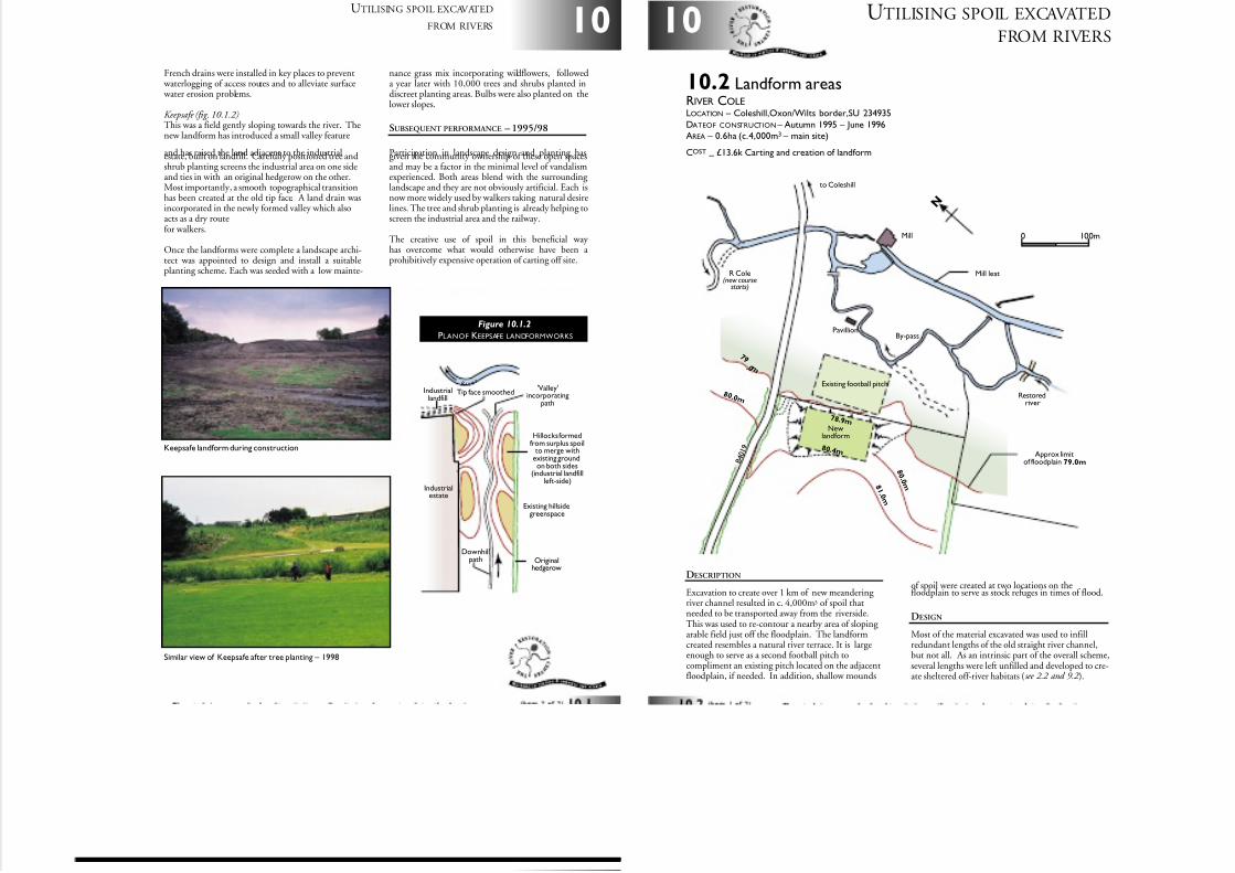
7/27/2019 MAN_mod
http://slidepdf.com/reader/full/manmod 83/84
10
UTILISING SPOIL EXCAVATED
FROM RIVERS
French drains were installed in key places to prevent waterlogging of access routes and to alleviate surface water erosion problems.
Keepsafe (fig. 10.1.2)This was a field gently sloping towards the river. Thenew landform has introduced a small valley feature
and has raised the land adjacent to the industrialestate, built on landfill. Carefully positioned tree andshrub planting screens the industrial area on one sideand ties in with an original hedgerow on the other.Most importantly, a smooth topographical transitionhas been created at the old tip face. A land drain wasincorporated in the newly formed valley which alsoacts as a dry routefor walkers.
Once the landforms were complete a landscape archi-tect was appointed to design and install a suitableplanting scheme. Each was seeded with a low mainte-
nance grass mix incorporating wildflowers, followeda year later with 10,000 trees and shrubs planted indiscreet planting areas. Bulbs were also planted on thelower slopes.
SUBSEQUENT PERFORMANCE – 1995/98
Participation in landscape design and planting hasgiven the community ownership of these open spacesand may be a factor in the minimal level of vandalismexperienced. Both areas blend with the surrounding landscape and they are not obviously artificial. Each isnow more widely used by walkers taking natural desirelines. The tree and shrub planting is already helping toscreen the industrial area and the railway.
The creative use of spoil in this beneficial way has overcome what would otherwise have been a prohibitively expensive operation of carting off site.
Tip face smoothedIndustriallandfill
'Valley'incorporating
path
Existing hillsidegreenspace
Originalhedgerow
Industrialestate
Hillocks formedfrom surplus spoil
to merge withexisting groundon both sides
(industrial landfillleft-side)
Downhillpath
R i v er
Figure 10.1.2
PLANOF KEEPSAFE LANDFORMWORKS
Keepsafe landform during construction
Similar view of Keepsafe after tree planting – 1998
UTILISING SPOIL EXCAVATED
FROM RIVERS10
DESCRIPTION
Excavation to create over 1 km of new meandering river channel resulted in c. 4,000m3 of spoil thatneeded to be transported away from the riverside.This was used to re-contour a nearby area of sloping arable field just off the floodplain. The landformcreated resembles a natural river terrace. It is largeenough to serve as a second football pitch tocompliment an existing pitch located on the adjacentfloodplain, if needed. In addition, shallow mounds
10.2 Landform areasRIVER COLELOCATION – Coleshill,Oxon/Wilts border,SU 234935
DATEOF CONSTRUCTION – Autumn 1995 – June 1996AREA – 0.6ha (c.4,000m3
– main site)
COST–
£13.6k Carting and creation of landform
N
0 100m
Existing football pitch
Newlandform
Pavillion
Mill
7 8 .9 m
8 0 .4 m
Restoredriver
R Cole(new course
starts)
to Coleshill
Approx limitof floodplain 79.0m
By-pass
Mill leat
B 4 0 1 9
8 1 . 0 m
8 0 . 0 m
8 0 . 0 m
7 9 . 0 m
of spoil were created at two locations on thefloodplain to serve as stock refuges in times of flood.
DESIGN
Most of the material excavated was used to infillredundant lengths of the old straight river channel,but not all. As an intrinsic part of the overall scheme,several lengths were left unfilled and developed to cre-ate sheltered off-river habitats (see 2.2 and 9.2 ).
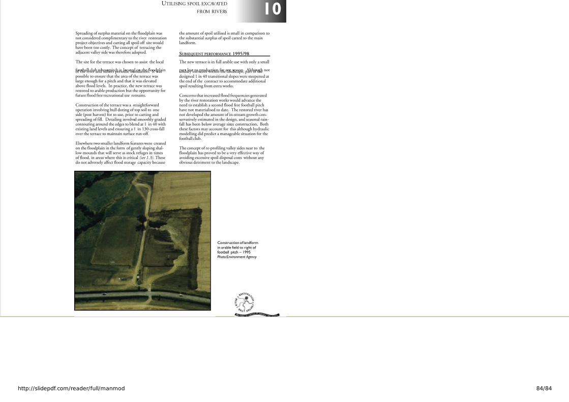
7/27/2019 MAN_mod
http://slidepdf.com/reader/full/manmod 84/84
10UTILISING SPOIL EXCAVATED
FROM RIVERS
Spreading of surplus material on the floodplain wasnot considered complimentary to the river restorationproject objectives and carting all spoil off site wouldhave been too costly. The concept of terracing theadjacent valley side was therefore adopted.
The site for the terrace was chosen to assist the local
football club whose pitch is located on the floodplainof the river and suffers periodic inundation. It waspossible to ensure that the area of the terrace waslarge enough for a pitch and that it was elevatedabove flood levels. In practice, the new terrace wasrestored to arable production but the opportunity forfuture flood free recreational use remains.
Construction of the terrace was a straightforwardoperation involving bull dozing of top soil to oneside (post harvest) for re-use, prior to carting andspreading of fill. Detailing involved smoothly gradedcontouring around the edges to blend at 1 in 40 withexisting land levels and ensuring a 1 in 130 cross-fallover the terrace to maintain surface run-off.
Elsewhere two smaller landform features were createdon the floodplain in the form of gently sloping shal-low mounds that will serve as stock refuges in timesof flood, in areas where this is critical (see 1.3). Thesedo not adversely affect flood storage capacity because
the amount of spoil utilised is small in comparison tothe substantial surplus of spoil carted to the mainlandform.
SUBSEQUENT PERFORMANCE 1995/98
The new terrace is in full arable use with only a small
part lost to production for one season. Although notunduly intrusive within the landscape, part of thedesigned 1 in 40 transitional slopes were steepened atthe end of the contract to accommodate additionalspoil resulting from extra works.
Concerns that increased flood frequencies generatedby the river restoration works would advance theneed to establish a second flood free football pitchhave not materialised to date. The restored river hasnot developed the amount of in-stream growth con-servatively estimated in the design, and seasonal rain-fall has been below average since construction. Boththese factors may account for this although hydraulicmodelling did predict a manageable situation for thefootball club.
The concept of re-profiling valley sides near to thefloodplain has proved to be a very effective way of avoiding excessive spoil disposal costs without any obvious detriment to the landscape.
Construction of landform
in arable field to right of football pitch – 1995Photo:Environment Agency


