Embed Size (px)
DESCRIPTION
Hohner Automazione encoders are high precision position/speed transducers. They are used to sample these quantitieson a revolving axle. The encoder converts the input analog signal to digital signal, so that it can be handled by a computerdevice. The conversion is carried out by a coded wheel, integral with the transducer shaft, read by a photoelectronicalsystem.
Citation preview

hohner Automazione hohne
ENCODER HANDBOOK
MAN_GB 3/97 RMAN_GB 3/97 RMAN_GB 3/97 RMAN_GB 3/97 RMAN_GB 3/97 Reeeeev 1.1v 1.1v 1.1v 1.1v 1.1
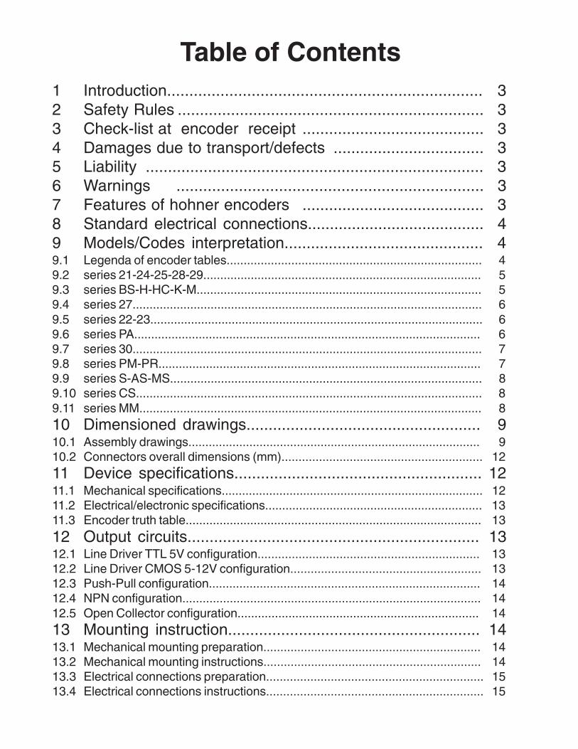
Table of Contents1 Introduction....................................................................... 32 Safety Rules ..................................................................... 33 Check-list at encoder receipt ......................................... 34 Damages due to transport/defects .................................. 35 Liability ............................................................................ 36 Warnings ..................................................................... 37 Features of hohner encoders ......................................... 38 Standard electrical connections........................................ 49 Models/Codes interpretation............................................. 49.1 Legenda of encoder tables........................................................................... 49.2 series 21-24-25-28-29.................................................................................. 59.3 series BS-H-HC-K-M.................................................................................... 59.4 series 27....................................................................................................... 69.5 series 22-23.................................................................................................. 69.6 series PA...................................................................................................... 69.7 series 30....................................................................................................... 79.8 series PM-PR............................................................................................... 79.9 series S-AS-MS............................................................................................ 89.10 series CS...................................................................................................... 89.11 series MM..................................................................................................... 810 Dimensioned drawings..................................................... 910.1 Assembly drawings...................................................................................... 910.2 Connectors overall dimensions (mm)........................................................... 1211 Device specifications........................................................ 1211.1 Mechanical specifications............................................................................. 1211.2 Electrical/electronic specifications................................................................ 1311.3 Encoder truth table....................................................................................... 1312 Output circuits.................................................................. 1312.1 Line Driver TTL 5V configuration................................................................. 1312.2 Line Driver CMOS 5-12V configuration........................................................ 1312.3 Push-Pull configuration................................................................................ 1412.4 NPN configuration........................................................................................ 1412.5 Open Collector configuration....................................................................... 1413 Mounting instruction......................................................... 1413.1 Mechanical mounting preparation................................................................ 1413.2 Mechanical mounting instructions................................................................ 1413.3 Electrical connections preparation................................................................ 1513.4 Electrical connections instructions................................................................ 15

1. IntroductionHohner Automazione encoders are high precision position/speed transducers. They are used to sample these quantitieson a revolving axle. The encoder converts the input analog signal to digital signal, so that it can be handled by a compu-ter device. The conversion is carried out by a coded wheel, integral with the transducer shaft, read by a photoelectronicalsystem.
2. Safety Rules- Hohner encoders are manufactured according to quality standards in the electrical/electronic field.- Leaving the manufacturing plant, they are safe for the operator; to mantain safety, please follow the rules
described in this handbook.- Take care when handling the encoder: as a metal device, it is a blunt instrument.- The encoder must be employed as to be expected. Any alteration in employment could prevent the correct
working.- The encoder must be used within limit values stated in the specifications listed in this handbook.- Our quality standards follow ISO9001 Certification.- Our safety and environmental standards follow CEE directives. The CE marking of our encoders states this
compliance.
3. Check-list at encoder receiptPlease immediately verify that:- goods are those described in the delivery note (number of items, type of material).- the encoder identification number is correct.- there are no damages due to transport and/or defects.
4. Damages due to transport/defects- If there are damages due to transport, please apply to the shipping agency.- If there are defects, please apply directly to Hohner.- In case of return of the goods, please use, if possible, the original package and enclose your name, address and
a description of the defect/s.
5. LiabilityPlease refer to conditions as per contract.
6. Warnings- Any alteration of the encoder, made by personnel not from Hohner or not authorized by Hohner, may prevent the
correct working and the safety guaranteed by the device; it is understood that, in these circumstances, theguarantee ceases and Hohner cannot be held responsible for subsequent damages to anybody/anything.
- The mounting instructions here enclosed are necessary to guarantee the correct and safe working of the device.Any other operation or employment of coupling accessories not recommended by Hohner may reduce the perfectworking order of the encoder.
- Encoders are high precision optoelectronic instruments, equipped with a precise mechanics to guarantee a linearconversion, so they must be handled with care.
- Prevent shocks on the assembly and especially on the encoder shaft. Do not apply an excessive load on theshaft.
7. Features of hohner encoders- The electronic parts are produced in mixed SMT and Micro SMT technology (Surface Mounting Technology).
This advanced technology guarantees a more precise construction and assembly of electronic components,improving reliability and durability.
- To prevent accidental failures, Hohner encoders are provided with electronic protection against short-circuits onsignal lines and polarity inversion on the power supply.

8. Standard electrical connectionsINCREMENTAL ENCODERS ABBREVIATIONS
-V +V A B Aneg.
Bneg.
0 0neg. bn = white bl = blue mr = brown vr = green
CABLE 5POLES bn mr vr gl - - gr - gl = yellow gr = grey ra = pink ro = red
CABLE 8POLES nr bl mr bg vr gl ra vl vl = violet bg = beige nr = black ar = orange
connector9414 Pin1 Pin2 Pin3 Pin4 - - Pin5 - nt = neutral
+ V = postivepower supply
- V = 0 Voltreference
conn. 9415for PR Pin1 Pin2 Pin3 Pin4 Pin5 Pin6 Pin7 Pin8 A = A channel B = B channel 0 = channel
reference
connector9413/15(PRoption H)/16/22
Pin1 Pin2 Pin3 Pin4 Pin5 Pin6 Pin7 Pin8A inverted =complementarychannel A
B inverted =complementarychannel B
0 inverted =complementaryreferencechannel
connector9418/19
PinA
PinB
PinC
PinD
PinE
PinF
PinG
Pin H(9419)
ABSOLUTE ENCODERS
-V +V1bit
2bit
3bit
4bit
5bit
6bit
7bit
8bit
9bit
10bit
11bit
12bit
latch / tristate /reset / preset
up -down
CABLE 14POLES nr bl mr bg vr gl ra vl ar nt bn / ro bn / bl - - gl / vr gl / bn
CABLE 16POLES nr ro mr bg gl vr ra vl gr bl ra / gr ro / bl vr / mr mr / gl bi / gl bn / vr
connector9416 Pin1 Pin2 Pin3 Pin4 Pin5 Pin6 Pin7 Pin8 Pin9 Pin10 Pin11 Pin12 - - - -
connector9413/26/ 28 Pin1 Pin2 Pin3 Pin4 Pin5 Pin6 Pin7 Pin8 Pin9 Pin10 Pin11 Pin12 Pin13 Pin14 Pin15 Pin16
ABSOLUTE MULTITOURN ENCODERS
-V +V1bit
2bit
3bit
4bit
5bit
6bit
7bit
8bit
9bit
10bit
11bit
12bit
13bit
14bit
15bit
connector9444
Pin1 Pin2 Pin3 Pin4 Pin5 Pin6 Pin7 Pin8 Pin9 Pin10 Pin 11 Pin12 Pin13 Pin14 Pin15 Pin16 Pin17
16bit
17bit
18bit
19bit
20bit
21bit
22bit
23bit
24bit
gray/binary
up -down
parityeven
parityodd
latch tristate strobe
Pin18 Pin19 Pin20 Pin21 Pin22 Pin23 Pin24 Pin25 Pin26 Pin38 Pin39 Pin40 Pin41 Pin42 Pin43 Pin 44
ATTENTION: FOR THE ELECTRICAL CONNECTION, ALWAYS REFER TO WHAT IS SPECIFIED ON THEENCODER LABEL, SINCE THERE MAY BE OUT OF STANDARD CONNECTIONS.
9. Models / codes interpretations
9.1 Legenda of encoder tables
LEGGENDA BOARDS
= diameterLATCH
= Input to freeze the output code of the encoder, also in motion, and read thecorrect position. The freeze lasts as long as the latch is activeLD = line-driver circuit
PP = Push-Pull circuit
STROBE
= output to state when the code reading is correct. 1) Static strobe: it’s relatedto the absolute position and lists the positions in wich the output code may notbe correct. Dynamic strobe: at any code change states, with a determinedduration pulse, that the code may not be correct.
OC = open collector circuit
A = A channel
B = B channelPARITY = Check-sum output bit; it is calculated on the sum of 1-bits of the position. It
can be even (check-sum even) or odd (check-sum odd).0 = reference channel
A inverted = complementary channel A
TRISTATE= Input used to temporarily disable the output, forcing it to high impedencestate. It is used, for example, to read outputs from several encodersconcurrently.
B inverted = complementary channel B
0 inverted = complementary referencechannel

9.2 Series.21-24-25-28-29.
MODELS SERIES 21-24-25-28-29
_ _ - 2 1* 2* 3* 4* / ∗∗∗∗
_ _ - 2 1* 2* 3* 4* / ∗∗∗∗SERIES SHAFT OUTPUTS VARIATIONS CONNECTIONS PULSES
21 25 series :5 = 6mm8 = 7mm9 = 5mm
0 = ABO 5/24V NPNA = Open collector
0 = 5P AXIAL CABLE
24 7 = AB 5/24V NPN 2 = 8P AXIAL CABLE
25 5 = A 5/24V NPN 0 = None 1 = 9415 9P AXIAL
28 21 series:1 = 6mm
1B = 3 = 9414 5P AXIAL
29 AB0+AB0 inverted LD-PP 8/24V 4 = 9422 8P AXIAL
24 series:4 = 6mm
2B = R = 5P RADIAL CABLE
AB+AB inverted LD-PP 8/24V 8 = 8P RADIAL CABLE
28 series:8 = 6mm
3B =
A+A inverted LD-PP 8/24V
29 series:9 = 6mm
80 =
AB0+AB0 inverted LD 5V
60 =
AB+AB inverted LD 5V
40 =
A+A inverted LD 5V
9.3 Series BS-H-HC-K-M.
MODELS SERIES BS-H-HC-K-M
_ _ - 1* 2* 3* 4* 5* / ∗∗∗∗
_ _ - 1* 2* 3* 4* 5* / ∗∗∗∗SERIES SHAFT FLANGE OUTPUTS CONNECTIONS VARIATIONS PULSES
BS 1= 10mm H series:1, 2, 3, 4, 6refer todrawing
1= A PP11/30V 0= 9414 Axial 0= None
H 3= 6mm 2= AB PP11/30V 2= 9414 Radial 1= High zero pulse
HC 4= 9,52mm 3= AB+0 inverted PP11/30V 3= Radial cable A= Special connections
K 6= 8mm HC series= 1 4= A+A inverted LD5V 4= 9418 Radial R= PULL-UP for A-B-C outputs
M BS series:0= 10mm1= 15mm6= 6mm7= 7mm
M series= 3 5= AB+AB inverted LD5V 5= 9416 Radial Z= Syncronized zero pulse onlyfor LD output.BS series:
this box isomitted
6= AB0+AB0 inverted LD5V 6= 9418 Axial
7= A+A inverted LD5/12V 7= 9419 Radial 5= 5V power supply for A,B,C +1,2,3 outputs8= AB+AB inverted LD5/12V 8= 9419 Axial
9= AB0+AB0 inverted LD5/12V 9= Axial cable
NOTE(1) The power supply varies from 11to 30 Volt, however the output voltagelevel is fixed at 5Volt(2) The power supply varies from 15to 24 Volt, however the output voltagelevel is fixed at 12Volt
A= A OC11/30V A= 9415 Axial
B= AB OC11/30V B= 9415 Radial
C= AB0 OC11/30V C= 9422 Radial
K=AB0+AB0 inverted LD11/30V(1) E= 9416 Axial
M= A+A inverted PP11/30V M= 9422 Axial
N= AB+AB inverted PP11/30V N= 9413 Axial
P= AB0+AB0 inverted PP11/30V
R= A+A inverted LD15/24V (2)
S=AB+AB inverted LD15/24V (2)
T=AB0+AB0 inverted LD15/24V (2)
hohner Automazione pag 5
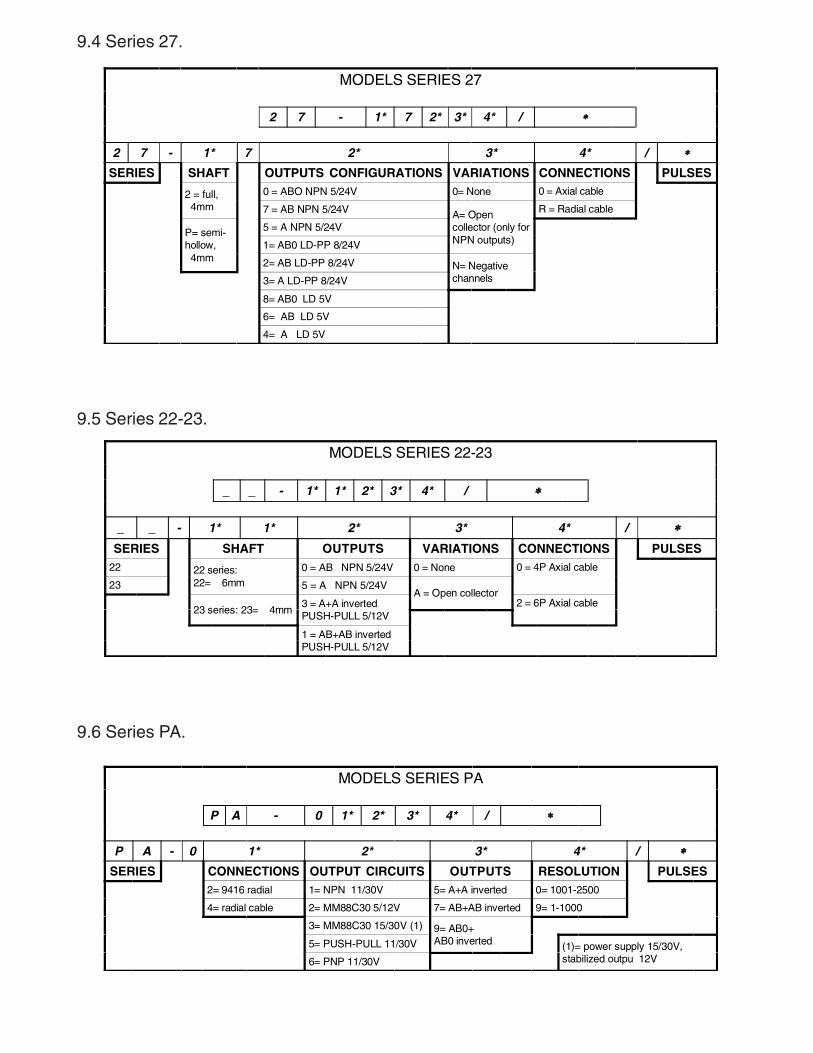
9.4 Series 27.
MODELS SERIES 27
2 7 - 1* 7 2* 3* 4* / ∗∗∗∗
2 7 - 1* 7 2* 3* 4* / ∗∗∗∗
SERIES SHAFT OUTPUTS CONFIGURATIONS VARIATIONS CONNECTIONS PULSES
2 = full, 4mm
0 = ABO NPN 5/24V 0= None 0 = Axial cable
7 = AB NPN 5/24V A= Opencollector (only forNPN outputs)
R = Radial cable
P= semi-hollow, 4mm
5 = A NPN 5/24V
1= AB0 LD-PP 8/24V
2= AB LD-PP 8/24V N= Negativechannels3= A LD-PP 8/24V
8= AB0 LD 5V
6= AB LD 5V
4= A LD 5V
9.5 Series 22-23.
MODELS SERIES 22-23
_ _ - 1* 1* 2* 3* 4* / ∗∗∗∗
_ _ - 1* 1* 2* 3* 4* / ∗∗∗∗SERIES SHAFT OUTPUTS VARIATIONS CONNECTIONS PULSES
22 22 series:22= 6mm
0 = AB NPN 5/24V 0 = None 0 = 4P Axial cable
23 5 = A NPN 5/24VA = Open collector
23 series: 23= 4mm3 = A+A invertedPUSH-PULL 5/12V
2 = 6P Axial cable
1 = AB+AB invertedPUSH-PULL 5/12V
9.6 Series PA.
MODELS SERIES PA
P A - 0 1* 2* 3* 4* / ∗∗∗∗
P A - 0 1* 2* 3* 4* / ∗∗∗∗
SERIES CONNECTIONS OUTPUT CIRCUITS OUTPUTS RESOLUTION PULSES2= 9416 radial 1= NPN 11/30V 5= A+A inverted 0= 1001-2500
4= radial cable 2= MM88C30 5/12V 7= AB+AB inverted 9= 1-1000
3= MM88C30 15/30V (1) 9= AB0+AB0 inverted5= PUSH-PULL 11/30V (1)= power supply 15/30V,
stabilized outpu 12V6= PNP 11/30V
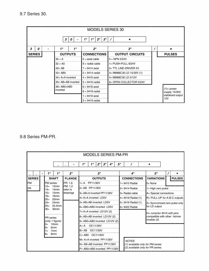
9.7 Series 30.
MODELS SERIES 30
3 0 - 1* 1* 2* 3* / ∗∗∗∗
3 0 - 1* 1* 2* 3* / ∗∗∗∗SERIES OUTPUTS CONNECTIONS OUTPUT CIRCUITS PULSES
30 = A 0 = axial cable 0 = NPN 5/24V
32 = A0 9 = radial cable 1= PUSH-PULL 8/24V
40= AB 7 = 9414 axial 2= TTL LINE-DRIVER 5V
42= AB0 2 = 9414 radial 3= MM88C30 LD 15/30V (1)
34= A+A inverted 4 = 9416 axial 4= MM88C30 LD 5/12V
35= AB+AB inverted 5 = 9416 radial 6= OPEN COLLECTOR 5/24V
36= AB0+AB0inverted
6 = 9418 axial(1)= powersupply 15/30V,stabilized output12V
8 = 9418 radial
1 = 9419 axial
3 = 9419 radial
9.8 Series PM-PR.
MODELS SERIES PM-PR
_ _ - 1* 1* 2* 3* 4* 5* / ∗∗∗∗
_ _ - 1* 1* 2* 3* 4* 5* / ∗∗∗∗SERIES SHAFT FLANGE OUTPUTS CONNECTIONS VARIATIONS PULSES
PM PM series:12= 12mm14= 14mm15= 15mm16= 16mm20= 20mm24= 24mm25= 25,4mm30= 30mm
PR: 1,6PM: 1,2refer todrawings
1= A PP11/30V 1= 9415 Radial 0= None
PR 2= AB PP11/30V 2= 9414 Radial 1= High zero pulse
3= AB+0 inverted PP11/30V 3= Radial cable A= Special connections
4= A+A inverted LD5V 4= 9418 Radial (1) R= PULL-UP for A-B-C outputs
5= AB+AB inverted LD5V 5= 9416 Radial (1) Z= Syncronized zero pulse onlyfor LD output6= AB0+AB0 inverted LD5V 6= 9422 Radial
7= A+A inverted LD12V (2)H= conector 9415 with pinscompatible with other hohnermodels (2)
PR series(only 1 figure):0= 10mm6= 6mm7= 7mm8= 8mm
8= AB+AB inverted LD12V (2)
9= AB0+AB0 inverted LD12V (2)
A= A OC11/30V
B= AB OC11/30V
C= AB0 OC11/30V
M= A+A inverted PP11/30V NOTES(1) available only for PM series(2) available only for PR series.
N= AB+AB inverted PP11/30V
P= AB0+AB0 inverted PP11/30V
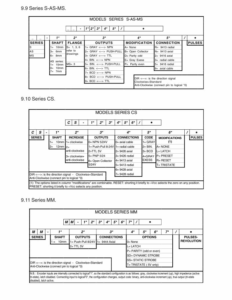
9.9 Series S-AS-MS.
MODELS SERIES S-AS-MS
_ _ - 1* 2* 3* 4* 5* / ∗∗∗∗
_ _ - 1* 2* 3* 4* 5* / ∗∗∗∗SERIES SHAFT FLANGE OUTPUTS MODIFICATION CONNECTION PULSESS 1= 10mm S= 1, 3, 6
refer todrawings
1= GRAY <----> NPN A= None R= 9413 radial
AS 3= 6mm 2= GRAY <---> PUSH-PULL B= Open Collector N= 9413 axial
MS 6= 8mm 3= GRAY <----> TTL D= Parity odd 2= 9416 axial
AS series:1= 15mm0= 10mm7= 7mm
4= BIN. <----> NPN E= Gray Exess 3= radial cable
MS= 3 5= BIN. <----> PUSH-PULL P= Parity even 5= 9416 radial
6= BIN. <----> TTL 9= axial cable
7= BCD <----> NPN
8= BCD <----> PUSH-PULLDIR <--->: is the direction signalClockwise=StandardAnti-Clockwise (connect pin to logical "0)
9= BCD <----> TTL
9.10 Series CS.
MODELS SERIES CS
C S - 1* 2* 3* 4* 5* 6* / ∗∗∗∗
C S - 1* 2* 3* 4* 5* 6* / ∗∗∗∗SERIES SHAFT INCREASE OUTPUTS CONNECTIONS CODE MODIFICATIONS
(1)PULSES
1= 10mm 1= clockwise 0= NPN 5/24V 0= axial cable 1= GRAY
2= 12mm 2=anti-clockwise
1= Push-Pull 8-24V 1= radial cable 2= BIN. A= NONE
2=TTL 5V 2= 9426 axial 3= BCD L= LATCH
3= clockwise+anti-clockwise
5= PNP 5/24 3= 9426 radial 4=GRAYEXESS
P= PRESET
6= Open Collector5/24V
4= 9413 axial R= RESET
5= 9413 radial T= TRISTATE
6= 9428 axial
DIR <--->: is the direction signal - Clockwise=StandardAnti-Clockwise (connect pin to logical "0)
7= 9428 radial
(1): The options listed in column "modifications" are combinable. RESET: shorting it briefly to +Vcc selects the zero on any position.PRESET: shorting it briefly to +Vcc selects any position.
9.11 Series MM.
MODELS SERIES MM
M M - 1* 2* 3* 4* 5* 6* 7* / ∗∗∗∗
M M - 1* 2* 3* 4* 5* 6* 7* / ∗∗∗∗SERIES SHAFT OUTPUTS CONNECTIONS OPTIONS PULSES-
REVOLUTION1 = 10mm 1= Push-Pull 8/24V 1= 9444 Axial 0= None
2= TTL 5V L= LATCH
P= PARITY (odd or even)
SD= DYNAMIC STROBE
DIR <--->: is the direction signal - Clockwise=StandardAnti-Clockwise (connect pin to logical "0)
SS= STATIC STROBE
T= TRISTATE ( 5V only)
N.B.: Encoder inputs are internally connected to logical"1", so the standard configuration is as follows: gray, clockwise increment (up), high impedence (activetri-state), latch disabled. Connecting input to logical"0", the configuration changes, output code: binary, anti-clockwise increment (up), true output (tri-statedisabled), latch active.
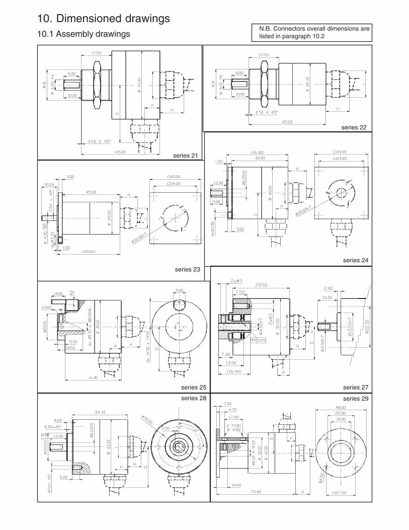
10. Dimensioned drawings10.1 Assembly drawings
series 21
series 22
series 23
series 25 series 27
series 29
series 24
N.B. Connectors overall dimensions arelisted in paragraph 10.2
series 28
.
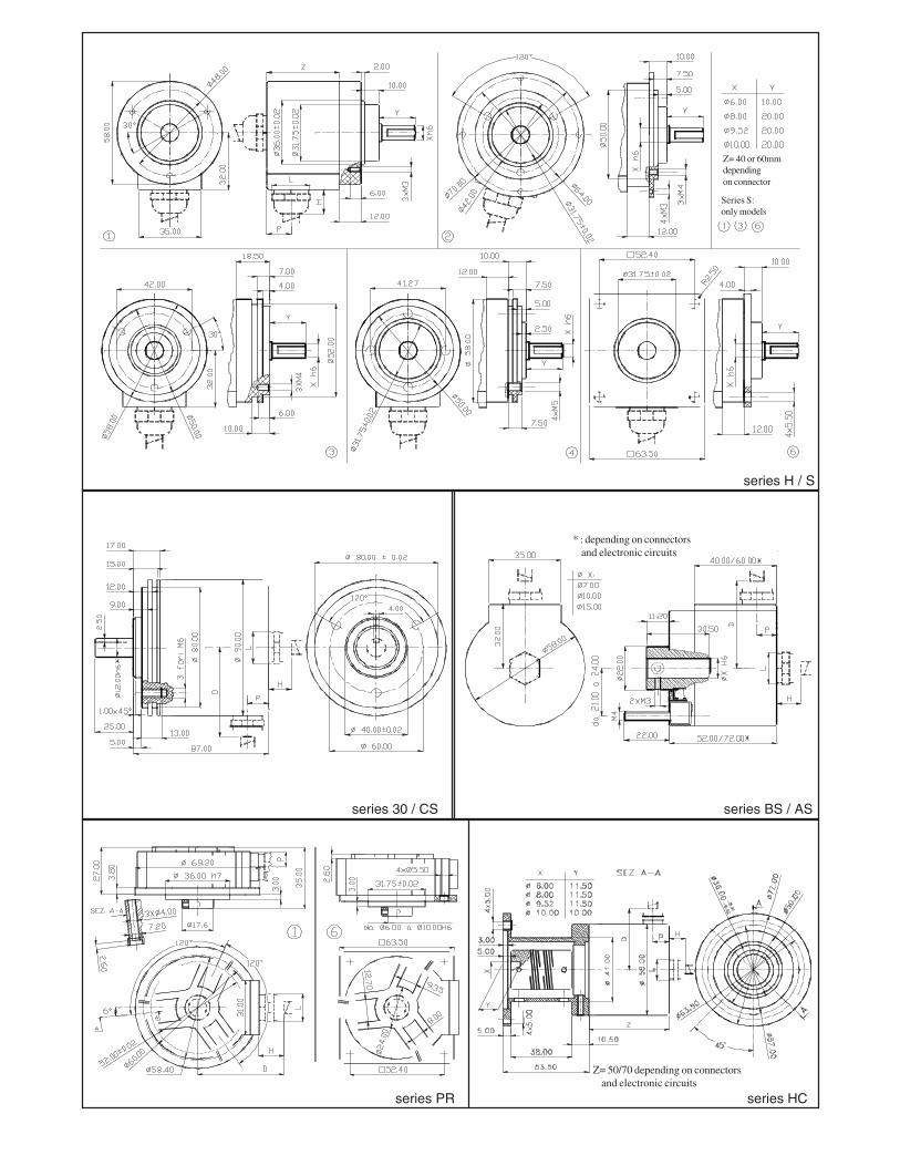
series HC
series BS / AS
series H / S
series PR
series 30 / CS
Z= 40 or 60mmdependingon connector
Series S:only models
* : depending on connectors and electronic circuits
Z= 50/70 depending on connectors and electronic circuits

..
.
.
.. . .
series K series M
series MS series MM
series PM series PA
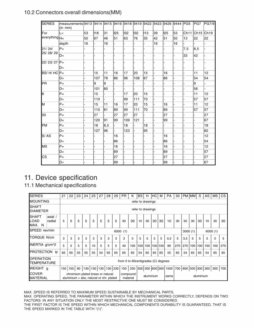
10.2 Connectors overall dimensions(MM)
SERIES measurements(in mm)
9413 9414 9415 9416 9418 9419 9422 9423 9426 9444 PG5 PG7 PG7/9
Foreverything
L= 53 ł18 31 ł25 ł32 ł32 ł13 39 ł25 53 Ch11 Ch15 Ch19
H= 50 67 46 51 63 76 35 42 51 50 13 22 22
depth 16 - 16 - - - - 16 - 16 - - -
21/ 24/25/ 28/ 29
P= - - - - - - - - - - 7,5 8,5 -
D= - - - - - - - - - - 33 42 -
22/ 23/ 27 P= - - - - - - - - - - - - -
D= - - - - - - - - - - - - -
BS/ H/ HC P= - 15 11 16 17 20 15 - 16 - - 11 12
D= - 107 78 86 96 108 67 - 86 - - 54 54
PR P= - 9 9 - - - - - - - - 9 -
D= - 101 80 - - - - - - - - 56 -
K P= - 15 - - 17 20 15 - - - - 11 12
D= - 110 - - 99 111 70 - - - - 57 57
M P= - 15 11 16 17 20 15 - 16 - - 11 12
D= - 110 81 89 99 111 70 - 89 - - 57 57
30 P= - 27 - 27 27 27 - - 27 - - - 27
D= - 120 91 99 109 121 - - 99 - - - 67
PM P= - 18 8,5 - 18 - 18 - - - - - 18
D= - 127 96 - 123 - 95 - - - - - 82
S/ AS P= - - - 16 - - - - 16 - - - 12
D= - - - 86 - - - - 86 - - - 54
MS P= - - - 16 - - - - 16 - - - 12
D= - - - 89 - - - - 89 - - - 57
CS P= - - - 27 - - - - 27 - - - 27
D= - - - 99 - - - - 99 - - - 67
11. Device specification11.1 Mechanical specifications
SERIES 21 22 23 24 25 27 28 29 PR K BS H HC M PA 30 PM MM S AS MS CS
MOUNTING refer to drawings
SHAFTDIAMETER refer to drawings
SHAFTLOADMAX. N
axial /radial 5 5 5 5 5 5 5 5 30 30 10 30 30 30 10 30 50 30 30 10 30 30
SPEED rev/min 6000 (1) 3000 (1) 6000 (1)
TORQUE N/cm 3 3 3 3 3 3 3 3 3 5 5 5 5 5 0,2 5 3,5 5 5 5 5 5
INERTIA g/cm^2 5 5 5 5 10 5 5 5 40 100 100 100 100 100 80 270 270 100 100 100 100 270
PROTECTION ip 65 65 55 55 55 54 65 65 65 65 54 65 65 65 55 65 54 65 65 54 65 65
OPERATIONTEMPERATURE from 0 to 60centigrades (C) degrees
WEIGHT g 150 150 90 130 130 130 130 230 150 250 300 300 600 300 1500 700 800 500 300 300 300 700
COVERMATERIAL
chromium plated brass or naturalaluminium + abs, natural or chr. plated
compoundmaterial
aluminium zama aluminium
MAX. SPEED IS REFERRED TO MAXIMUM SPEED SUSTAINABLE BY MECHANICAL PARTS.MAX. OPERATING SPEED, THE PARAMETER WITHIN WHICH THE INSTRUMENT WORKS CORRECTLY, DEPENDS ON TWOFACTORS: IN ANY SITUATION ONLY THE MOST RESTRICTIVE ONE MUST BE CONSIDERED.THE FIRST FACTOR IS THE SPEED WITHIN WHICH MECHANICAL COMPONENTS DURABILITY IS GUARANTEED, THAT ISTHE SPEED MARKED IN THE TABLE WITH “(1)”.
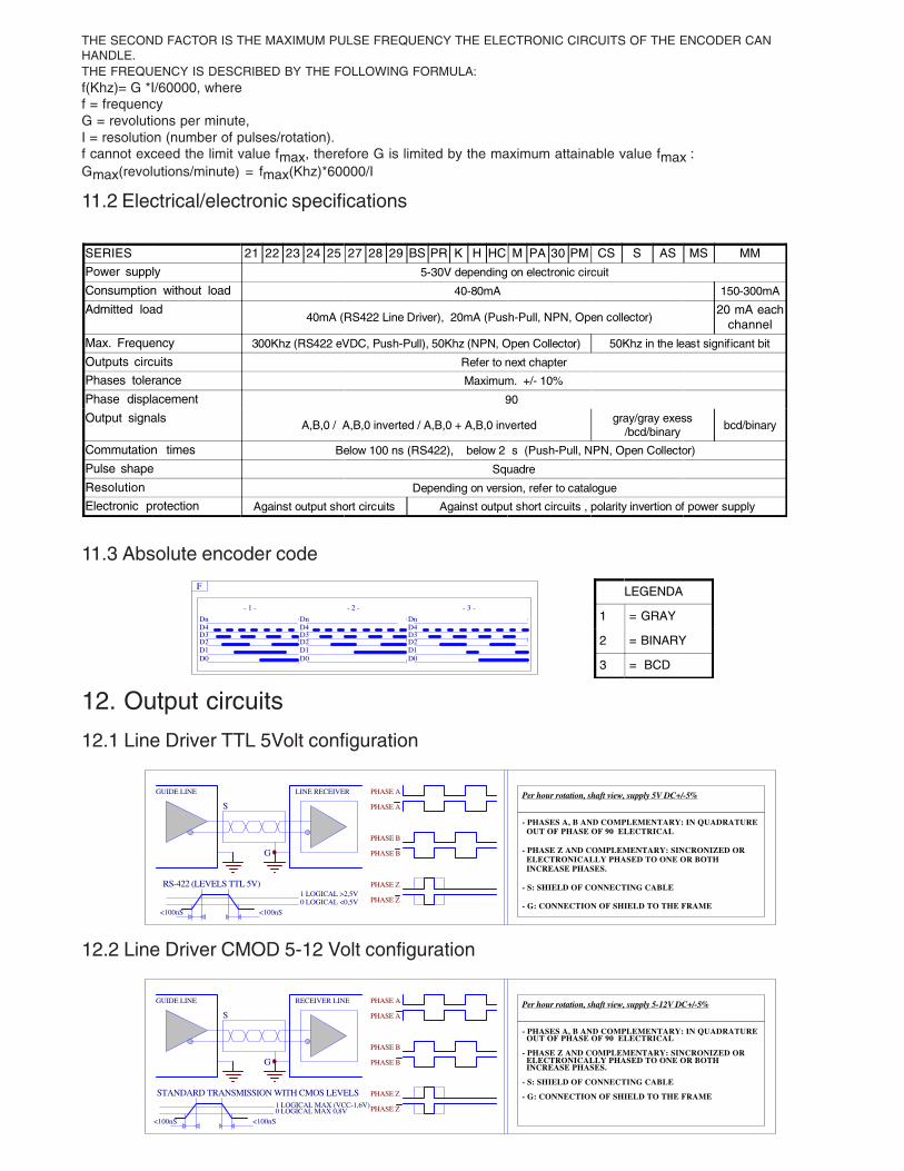
THE SECOND FACTOR IS THE MAXIMUM PULSE FREQUENCY THE ELECTRONIC CIRCUITS OF THE ENCODER CANHANDLE.THE FREQUENCY IS DESCRIBED BY THE FOLLOWING FORMULA:f(Khz)= G *I/60000, wheref = frequencyG = revolutions per minute,I = resolution (number of pulses/rotation).f cannot exceed the limit value fmax, therefore G is limited by the maximum attainable value fmax :Gmax(revolutions/minute) = fmax(Khz)*60000/I
11.2 Electrical/electronic specifications
SERIES 21 22 23 24 25 27 28 29 BS PR K H HC M PA 30 PM CS S AS MS MM
Power supply 5-30V depending on electronic circuit
Consumption without load 40-80mA 150-300mA
Admitted load40mA (RS422 Line Driver), 20mA (Push-Pull, NPN, Open collector)
20 mA eachchannel
Max. Frequency 300Khz (RS422 eVDC, Push-Pull), 50Khz (NPN, Open Collector) 50Khz in the least significant bit
Outputs circuits Refer to next chapter
Phases tolerance Maximum. +/- 10%
Phase displacement 90
Output signals A,B,0 / A,B,0 inverted / A,B,0 + A,B,0 inverted
gray/gray exess/bcd/binary bcd/binary
Commutation times Below 100 ns (RS422), below 2 s (Push-Pull, NPN, Open Collector)
Pulse shape Squadre
Resolution Depending on version, refer to catalogue
Electronic protection Against output short circuits Against output short circuits , polarity invertion of power supply
11.3 Absolute encoder code
F
D0D1D2D3D4Dn
D0D1D2D3D4Dn
D0D1D2D3D4Dn
- 1 - - 2 - - 3 -
LEGENDA
1 = GRAY
2 = BINARY
3 = BCD
12. Output circuits
12.1 Line Driver TTL 5Volt configuration
RS-422 (LEVELS TTL 5V)
S
G
LINE RECEIVERGUIDE LINE
PHASE A
PHASE A
PHASE B
PHASE B
PHASE Z
PHASE Z
- PHASES A, B AND COMPLEMENTARY: IN QUADRATURE OUT OF PHASE OF 90 ELECTRICAL
- PHASE Z AND COMPLEMENTARY: SINCRONIZED OR ELECTRONICALLY PHASED TO ONE OR BOTH INCREASE PHASES.
- S: SHIELD OF CONNECTING CABLE
- G: CONNECTION OF SHIELD TO THE FRAME<100nS <100nS
1 LOGICAL >2,5V0 LOGICAL <0,5V
Per hour rotation, shaft view, supply 5V DC+/-5%
12.2 Line Driver CMOD 5-12 Volt configuration
STANDARD TRANSMISSION WITH CMOS LEVELS
S
G
RECEIVER LINEGUIDE LINE
<100nS <100nS
1 LOGICAL MAX (VCC-1,6V)0 LOGICAL MAX 0,8V
PHASE A
PHASE A
PHASE B
PHASE B
PHASE Z
PHASE Z
- PHASES A, B AND COMPLEMENTARY: IN QUADRATURE OUT OF PHASE OF 90 ELECTRICAL
- PHASE Z AND COMPLEMENTARY: SINCRONIZED OR ELECTRONICALLY PHASED TO ONE OR BOTH INCREASE PHASES.
- S: SHIELD OF CONNECTING CABLE
- G: CONNECTION OF SHIELD TO THE FRAME
Per hour rotation, shaft view, supply 5-12V DC+/-5%

12.3 Push-Pull configuration
BIPOLAR TYPE TRANSMISSION
S
G
RECEIVER
<=2uS <=2uS
VCC
F
F
ENC
TRANSMITTER
(C1)
(C2)
PHASE A
PHASE A
PHASE B
PHASE B
PHASE Z
PHASE Z
- PHASES A, B AND COMPLEMENTARY: IN QUADRATURE OUT OF PHASE OF 90 ELECTRICAL
- PHASE Z AND COMPLEMENTARY: SINCRONIZED OR ELECTRONICALLY PHASED TO ONE OR BOTH INCREASE PHASES.
- S: SHIELD OF CONNECTING CABLE
- G: CONNECTION OF SHIELD TO THE FRAME
- C1: NPN LOAD (CURRENT SINK) C2: PNP LOAD (CURRENT SOURCE)
Per hour rotation, shaft view, supply 8-24V DC +/- 10%
12.4 NPN configuration
BIPOLAR TYPE TRANSMISSION
S
G
RECEIVER PHASE A
PHASE B
PHASE Z
<=2uS <=2uS
VCC
FENC
TRANSMITTER
(C)
RC
PHASE Z
(1)
(2)
- PHASE A,B:IN QUADRATURE OUT OF PHASE OF 90 ELEC
- PHASE Z: ACTIVE HIGH (1) OR LOW (2) SYNCRONIZED TO ONE OF THE INCREASE PHASES
- S: SHIELD OF CONNECTING CABLE
- G: CONNECTION OF SHIELD TO THE FRAME
- (C): NPN LOAD ( CURRENT SINK)
Per hour rotation, shaft view, supply 8-24V DC+/- 10%
12.5 Open Collector configuration
BIPOLAR TYPE TRANSMISSION
S
G
RECEIVER
<=2uS <=2uS
VCC
FENC
TRANSMITTER
(C)
PHASE A
PHASE B
PHASE Z
PHASE Z
(1)
(2)
- PHASE A,B:IN QUADRATURE OUT OF PHASE OF 90 ELEC
- PHASE Z: ACTIVE HIGH (1) OR LOW (2) SYNCRONIZED TO ONE OF THE INCREASE PHASES
- S: SHIELD OF CONNECTING CABLE
- G: CONNECTION OF SHIELD TO THE FRAME
- (C): NPN LOAD ( CURRENT SINK)
Per hour rotation, shaft view, supply 8-24V DC +/- 10%
13. Mounting instruction
13.1 Mechanical assembly preparationIf you are employing adapters for the shafts (joints) and for the encoder (flange coupling), please verify on the encloseddrawings that they are suitable for the encoder series employed.If the adapters are not Hohner products, please make sure that:
-the encoder can be mounted rigidly and reliably-any dis-alignment and/or axis-error of the shafts to be coupled must be within the limits listed for the encoder and/or the eventual joint.
13.2 Mechanical mounting instructionsPlease refer to the assembly drawing at the end of this paragraph.Mount the eventual flange coupling on the encoder.Mount the eventual joint to the axle you are installing the encoder on.Connect the encoder shaft to the axle (eventually through the joint) positioning the encoder so that it can be later fixedon the machine.Mount the body of the encoder on the machine (eventually through the flange coupling or in other way)Verify that all screws are correctly tighten.
Attention:the body of the encoder is usually made, due to lightness requirements, of aluminium or compsites(resins with short fibres), do not apply an excessive torque when tightening a screw in a thread on theencoder body.
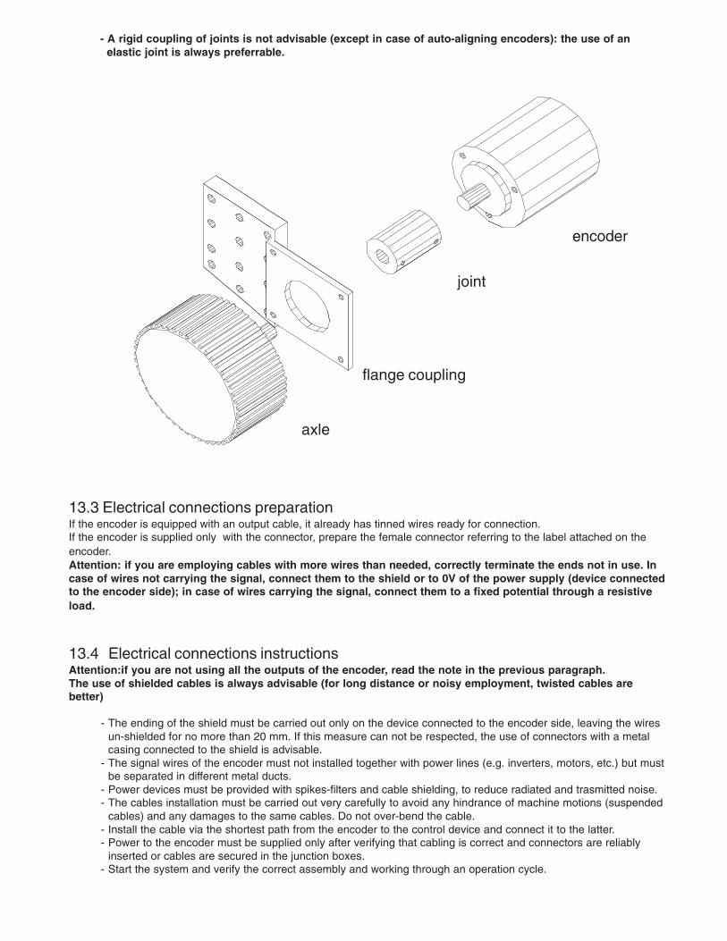
- A rigid coupling of joints is not advisable (except in case of auto-aligning encoders): the use of an elastic joint is always preferrable.
13.3 Electrical connections preparationIf the encoder is equipped with an output cable, it already has tinned wires ready for connection.If the encoder is supplied only with the connector, prepare the female connector referring to the label attached on theencoder.Attention: if you are employing cables with more wires than needed, correctly terminate the ends not in use. Incase of wires not carrying the signal, connect them to the shield or to 0V of the power supply (device connectedto the encoder side); in case of wires carrying the signal, connect them to a fixed potential through a resistiveload.
13.4 Electrical connections instructionsAttention:if you are not using all the outputs of the encoder, read the note in the previous paragraph.The use of shielded cables is always advisable (for long distance or noisy employment, twisted cables arebetter)
- The ending of the shield must be carried out only on the device connected to the encoder side, leaving the wiresun-shielded for no more than 20 mm. If this measure can not be respected, the use of connectors with a metalcasing connected to the shield is advisable.
- The signal wires of the encoder must not installed together with power lines (e.g. inverters, motors, etc.) but mustbe separated in different metal ducts.
- Power devices must be provided with spikes-filters and cable shielding, to reduce radiated and trasmitted noise. - The cables installation must be carried out very carefully to avoid any hindrance of machine motions (suspended
cables) and any damages to the same cables. Do not over-bend the cable. - Install the cable via the shortest path from the encoder to the control device and connect it to the latter. - Power to the encoder must be supplied only after verifying that cabling is correct and connectors are reliably
inserted or cables are secured in the junction boxes. - Start the system and verify the correct assembly and working through an operation cycle.
encoder
flange coupling
joint
axle