Embed Size (px)
Citation preview
MANAGING DYNAMIC NON-UNIFORM
CACHE ARCHITECTURES
Javier Lira Rueda
Department of Computer Architecture
Universitat Politècnica de Catalunya
Advisors:
Carlos Molina
Universitat Rovira i Virgili
Antonio González
Intel Barcelona Research Center
Intel Labs, Universitat Politècnica de Catalunya
A THESIS SUBMITTED IN FULFILLMENTOF THE REQUIREMENTS FOR THE DEGREE OF
Doctor per la Universitat Politècnica de Catalunya

Alguien me dijo una vez:
“No hay nada más bonito que una familia unida”.
Esta tesis se la dedico a mis padres, mi hermana y Eva:
Mi familia.
i

ii
ACKNOWLEDGEMENTS
Mi madre siempre me dice que “es de bien nacido ser agradecido”. Pues a ello voy. En
primer lugar quisiera agradecer precisamente a mis padres y a mi hermana el apoyo
incondicional que me han ofrecido durante la realización de la tesis, y en general
durante toda mi vida. Sois los mejores!
También estoy especialmente agradecido por la supervisión y apoyo que he
recibido por parte de Carlos. Sinceramente, creo que no he podido caer en mejores
manos. Sin duda, él tiene gran parte de culpa de que hoy esté escribiendo estas líneas.
Mención especial también para Antonio, quien me dio la oportunidad de entrar en
el maravilloso mundo de la investigación y de la arquitectura de computadores. Un
mundo realmente fascinante! No me quiero olvidar de Alex, que fue la persona que
me habló por primera vez del doctorado e hizo que me picara el gusanillo de la
investigación.
No quiero olvidarme de la gente que ha hecho que en los días duros de trabajo,
como cuando me rechazan un artículo, petan las simulaciones o no acompaÃsan los
resultados, siempre tenga una sonrisa en la cara y ganas de pasarlo bien. Ellos son
mis compañeros de la sala D6-116, gente del departamento, y sobretodo, la plantilla
al completo de “The Blue Brothers”. Vosotros me hacéis realmente feliz y merecéis ser
nombrados: Demos, Aleksandar, Rakesh, Xavi, Martí, Manu, Ignasi, Gemma, Oscar,
Enric, Niko, Marc, René, Iñigo, Milan, Pedro, Josep Maria, Nehir, Mario, y otros
muchos que seguro que me dejo. Gracias!
La última persona que me queda por agradecer es Eva. Eres la persona más
especial que he conocido nunca. Tu ambición es mi ambición y la que me dio el último
empujoncito para comenzar la tesis, y que hoy esté escribiendo estas líneas. Tu apoyo
en todos los momentos de la tesis ha sido decisivo e incondicional. Gracias por todo y
por estar a mi lado.
iii

iv
ABSTRACT
Researchers from both academia and industry agree that future CMPs will
accommodate large shared on-chip last-level caches. However, the exponential
increase in multicore processor cache sizes accompanied by growing on-chip wire
delays make it difficult to implement traditional caches with a single, uniform access
latency. Non-Uniform Cache Access (NUCA) designs have been proposed to address
this situation. A NUCA cache divides the whole cache memory into smaller banks
that are distributed along the chip and can be accessed independently. Response time
in NUCA caches does not only depend on the latency of the actual bank, but also on
the time required to reach the bank that has the requested data and to send it to the
core. So, the NUCA cache allows those banks that are located next to the cores to have
lower access latencies than the banks that are further away, thus mitigating the effects
of the cache’s internal wires.
These cache architectures have been traditionally classified based on their
placement decisions as static (S-NUCA) or dynamic (D-NUCA). In this thesis, we have
focused on D-NUCA as it exploits the dynamic features that NUCA caches offer, like
data migration. The flexibility that D-NUCA provides, however, raises new challenges
that hardens the management of this kind of cache architectures in CMP systems. We
have identified these new challenges and tackled them from the point of view of the
four NUCA policies: replacement, access, placement and migration.
First, we focus on the challenges introduced by the replacement policy in D-NUCA.
Data migration makes most frequently accessed data blocks to be concentrated on the
banks that are closer to the processors. This creates big differences in the average usage
rate of the NUCA banks, being the banks that are close to the processors the most
accessed banks, while the banks that are further away are not accessed so often. Upon
a replacement in a particular bank of the NUCA cache, the probabilities of the evicted
data block to be reused by the program will differ if its last location in the NUCA
v
cache was a bank that are close to the processors, or not. The decentralized nature of
NUCA, however, prevents a NUCA bank from knowing that other bank is constantly
evicting data blocks that are later being reused. We propose three different techniques
to deal with the replacement policy, being The Auction the most successful one. This is a
framework that allows architects for implementing auction-like replacement policies
in future D-NUCA cache architectures. The Auction spreads replacement decisions
that have been taken in a single bank to the whole NUCA cache. Therefore, this enables
the replacement policy to select the most appropriate victim data block from the whole
NUCA cache.
Then, we deal with the challenges in the access policy. As data blocks can be
mapped in multiple banks within the NUCA cache. Finding the requesting data in
a D-NUCA cache is a difficult task. In addition, data can freely move between these
banks, thus the search scheme must look up all banks where the requesting data block
can be mapped to ascertain if it is in the NUCA cache, or not. We have proposed
HK-NUCA. This is a search scheme that uses home knowledge to effectively reduce the
average number of messages introduced to the on-chip network to satisfy a memory
request.
With regard to the placement policy, this thesis shows the implementation of a
hybrid NUCA cache. We have proposed a novel placement policy that accomodates
both memory technologies, SRAM and eDRAM, in a single NUCA cache. This takes
advantage of the fast SRAM caches to store there the most accessed data blocks, while
other data that have not been accessed, or has been evicted from SRAM banks are
stored in the eDRAM banks.
Finally, in order to deal with the migration policy in D-NUCA caches, we propose
The Migration Prefetcher. This is a technique that anticipates data migrations. This
mechanism recognizes access patterns based on the history, and promotes the potential
follower of the current memory access before the next memory access actually
happens. When The Migration Prefetcher hits on the prediction, the memory access
vi
finishes in few cycles, instead of more than one hundred, that is what it takes when
the data block is in the furthest bank.
Summarizing, in this thesis we propose different techniques to efficiently manage
future D-NUCA cache architectures on CMPs. We demonstrate the effectivity of our
techniques to deal with the challenges introduced by D-NUCA caches. Our techniques
outperform existing solutions in the literature, and are in most cases more energy
efficient.
vii

viii
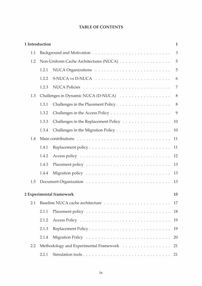
TABLE OF CONTENTS
1 Introduction 1
1.1 Background and Motivation . . . . . . . . . . . . . . . . . . . . . . . . . . 3
1.2 Non-Uniform Cache Architectures (NUCA) . . . . . . . . . . . . . . . . . 5
1.2.1 NUCA Organizations . . . . . . . . . . . . . . . . . . . . . . . . . 5
1.2.2 S-NUCA vs D-NUCA . . . . . . . . . . . . . . . . . . . . . . . . . 6
1.2.3 NUCA Policies . . . . . . . . . . . . . . . . . . . . . . . . . . . . . 7
1.3 Challenges in Dynamic NUCA (D-NUCA) . . . . . . . . . . . . . . . . . 8
1.3.1 Challenges in the Placement Policy . . . . . . . . . . . . . . . . . . 8
1.3.2 Challenges in the Access Policy . . . . . . . . . . . . . . . . . . . . 9
1.3.3 Challenges in the Replacement Policy . . . . . . . . . . . . . . . . 10
1.3.4 Challenges in the Migration Policy . . . . . . . . . . . . . . . . . . 10
1.4 Main contributions . . . . . . . . . . . . . . . . . . . . . . . . . . . . . . . 11
1.4.1 Replacement policy . . . . . . . . . . . . . . . . . . . . . . . . . . . 11
1.4.2 Access policy . . . . . . . . . . . . . . . . . . . . . . . . . . . . . . 12
1.4.3 Placement policy . . . . . . . . . . . . . . . . . . . . . . . . . . . . 13
1.4.4 Migration policy . . . . . . . . . . . . . . . . . . . . . . . . . . . . 13
1.5 Document Organization . . . . . . . . . . . . . . . . . . . . . . . . . . . . 13
2 Experimental framework 15
2.1 Baseline NUCA cache architecture . . . . . . . . . . . . . . . . . . . . . . 17
2.1.1 Placement policy . . . . . . . . . . . . . . . . . . . . . . . . . . . . 18
2.1.2 Access Policy . . . . . . . . . . . . . . . . . . . . . . . . . . . . . . 19
2.1.3 Replacement Policy . . . . . . . . . . . . . . . . . . . . . . . . . . . 19
2.1.4 Migration Policy . . . . . . . . . . . . . . . . . . . . . . . . . . . . 20
2.2 Methodology and Experimental Framework . . . . . . . . . . . . . . . . 21
2.2.1 Simulation tools . . . . . . . . . . . . . . . . . . . . . . . . . . . . . 21
ix
2.2.2 Simulated scenarios . . . . . . . . . . . . . . . . . . . . . . . . . . 23
2.2.3 Experimental methodology . . . . . . . . . . . . . . . . . . . . . . 26
2.2.4 Energy Model . . . . . . . . . . . . . . . . . . . . . . . . . . . . . . 27
3 Replacement policy 29
3.1 Introduction . . . . . . . . . . . . . . . . . . . . . . . . . . . . . . . . . . . 31
3.2 Last Bank . . . . . . . . . . . . . . . . . . . . . . . . . . . . . . . . . . . . . 33
3.2.1 Last Bank Optimizations . . . . . . . . . . . . . . . . . . . . . . . . 35
3.2.2 Results and analysis . . . . . . . . . . . . . . . . . . . . . . . . . . 37
3.2.3 Summary . . . . . . . . . . . . . . . . . . . . . . . . . . . . . . . . 38
3.3 LRU-PEA . . . . . . . . . . . . . . . . . . . . . . . . . . . . . . . . . . . . . 38
3.3.1 Data Eviction Policy . . . . . . . . . . . . . . . . . . . . . . . . . . 39
3.3.2 Data Target Policy . . . . . . . . . . . . . . . . . . . . . . . . . . . 41
3.3.3 Additional Hardware . . . . . . . . . . . . . . . . . . . . . . . . . 44
3.3.4 Results and analysis . . . . . . . . . . . . . . . . . . . . . . . . . . 44
3.4 The Auction . . . . . . . . . . . . . . . . . . . . . . . . . . . . . . . . . . . 49
3.4.1 Roles and components . . . . . . . . . . . . . . . . . . . . . . . . . 49
3.4.2 How The Auction works . . . . . . . . . . . . . . . . . . . . . . . . 51
3.4.3 Hardware Implementation and Overhead . . . . . . . . . . . . . . 52
3.4.4 Implementing an Auction Approach . . . . . . . . . . . . . . . . . 53
3.4.5 Results and analysis . . . . . . . . . . . . . . . . . . . . . . . . . . 56
3.5 Related Work . . . . . . . . . . . . . . . . . . . . . . . . . . . . . . . . . . 62
3.6 Conclusions . . . . . . . . . . . . . . . . . . . . . . . . . . . . . . . . . . . 63
4 Access policy 65
4.1 Introduction . . . . . . . . . . . . . . . . . . . . . . . . . . . . . . . . . . . 67
4.2 Motivation . . . . . . . . . . . . . . . . . . . . . . . . . . . . . . . . . . . . 67
4.2.1 Locating data within the NUCA cache . . . . . . . . . . . . . . . . 69
4.2.2 Exploiting spatial/temporal locality . . . . . . . . . . . . . . . . . 71
x
4.3 HK-NUCA . . . . . . . . . . . . . . . . . . . . . . . . . . . . . . . . . . . . 72
4.3.1 How HK-NUCAworks . . . . . . . . . . . . . . . . . . . . . . . . 73
4.3.2 Managing Home Knowledge . . . . . . . . . . . . . . . . . . . . . 75
4.3.3 Implementing HK-NUCA . . . . . . . . . . . . . . . . . . . . . . . 77
4.4 Results and analysis . . . . . . . . . . . . . . . . . . . . . . . . . . . . . . 77
4.4.1 Performance analysis . . . . . . . . . . . . . . . . . . . . . . . . . . 78
4.4.2 Energy consumption analysis . . . . . . . . . . . . . . . . . . . . . 82
4.5 Related work . . . . . . . . . . . . . . . . . . . . . . . . . . . . . . . . . . . 84
4.6 Conclusions . . . . . . . . . . . . . . . . . . . . . . . . . . . . . . . . . . . 86
5 Placement policy 87
5.1 Introduction . . . . . . . . . . . . . . . . . . . . . . . . . . . . . . . . . . . 89
5.2 SRAM vs eDRAM . . . . . . . . . . . . . . . . . . . . . . . . . . . . . . . . 90
5.3 Implementing a hybrid NUCA cache . . . . . . . . . . . . . . . . . . . . . 92
5.3.1 The two hybrid approaches . . . . . . . . . . . . . . . . . . . . . . 92
5.3.2 Placement policy for heterogeneous bankcluster . . . . . . . . . . 94
5.3.3 Tag Directory Array (TDA) . . . . . . . . . . . . . . . . . . . . . . 96
5.3.4 Performance and power analysis . . . . . . . . . . . . . . . . . . . 98
5.4 Results and analysis . . . . . . . . . . . . . . . . . . . . . . . . . . . . . . 99
5.4.1 Performance Analysis . . . . . . . . . . . . . . . . . . . . . . . . . 101
5.4.2 Power and Area Analysis . . . . . . . . . . . . . . . . . . . . . . . 103
5.4.3 Choosing the best hybrid configuration . . . . . . . . . . . . . . . 104
5.5 Exploiting architectural benefits . . . . . . . . . . . . . . . . . . . . . . . . 106
5.6 Related Work . . . . . . . . . . . . . . . . . . . . . . . . . . . . . . . . . . 107
5.7 Conclusions . . . . . . . . . . . . . . . . . . . . . . . . . . . . . . . . . . . 109
6 Migration policy 111
6.1 Introduction . . . . . . . . . . . . . . . . . . . . . . . . . . . . . . . . . . . 113
6.2 Motivation . . . . . . . . . . . . . . . . . . . . . . . . . . . . . . . . . . . . 114
xi
6.3 The Migration Prefetcher . . . . . . . . . . . . . . . . . . . . . . . . . . . . 116
6.3.1 How the prefetcher works . . . . . . . . . . . . . . . . . . . . . . . 116
6.3.2 Prefetching strategies . . . . . . . . . . . . . . . . . . . . . . . . . 119
6.3.3 Accuracy . . . . . . . . . . . . . . . . . . . . . . . . . . . . . . . . . 121
6.3.4 Lookup in NUCA . . . . . . . . . . . . . . . . . . . . . . . . . . . . 122
6.3.5 Tuning the prefetcher . . . . . . . . . . . . . . . . . . . . . . . . . 123
6.4 Results and analysis . . . . . . . . . . . . . . . . . . . . . . . . . . . . . . 124
6.4.1 Performance Analysis . . . . . . . . . . . . . . . . . . . . . . . . . 125
6.4.2 Energy Consumption Analysis . . . . . . . . . . . . . . . . . . . . 129
6.4.3 Summary . . . . . . . . . . . . . . . . . . . . . . . . . . . . . . . . 131
6.5 Related work . . . . . . . . . . . . . . . . . . . . . . . . . . . . . . . . . . . 131
6.6 Conclusions . . . . . . . . . . . . . . . . . . . . . . . . . . . . . . . . . . . 133
7 Conclusions and future work 135
7.1 Conclusions . . . . . . . . . . . . . . . . . . . . . . . . . . . . . . . . . . . 137
7.2 Future work . . . . . . . . . . . . . . . . . . . . . . . . . . . . . . . . . . . 139
References 140
List of tables 150
List of figures 152
xii
Chapter 1
Introduction
This chapter motivates the introduction of Non-Uniform Cache Architectures (NUCAs) in
chip-multiprocessors. In addition, it describes the new challenges brought by this kind of caches,
and presents the contributions of this thesis.

Introduction 3
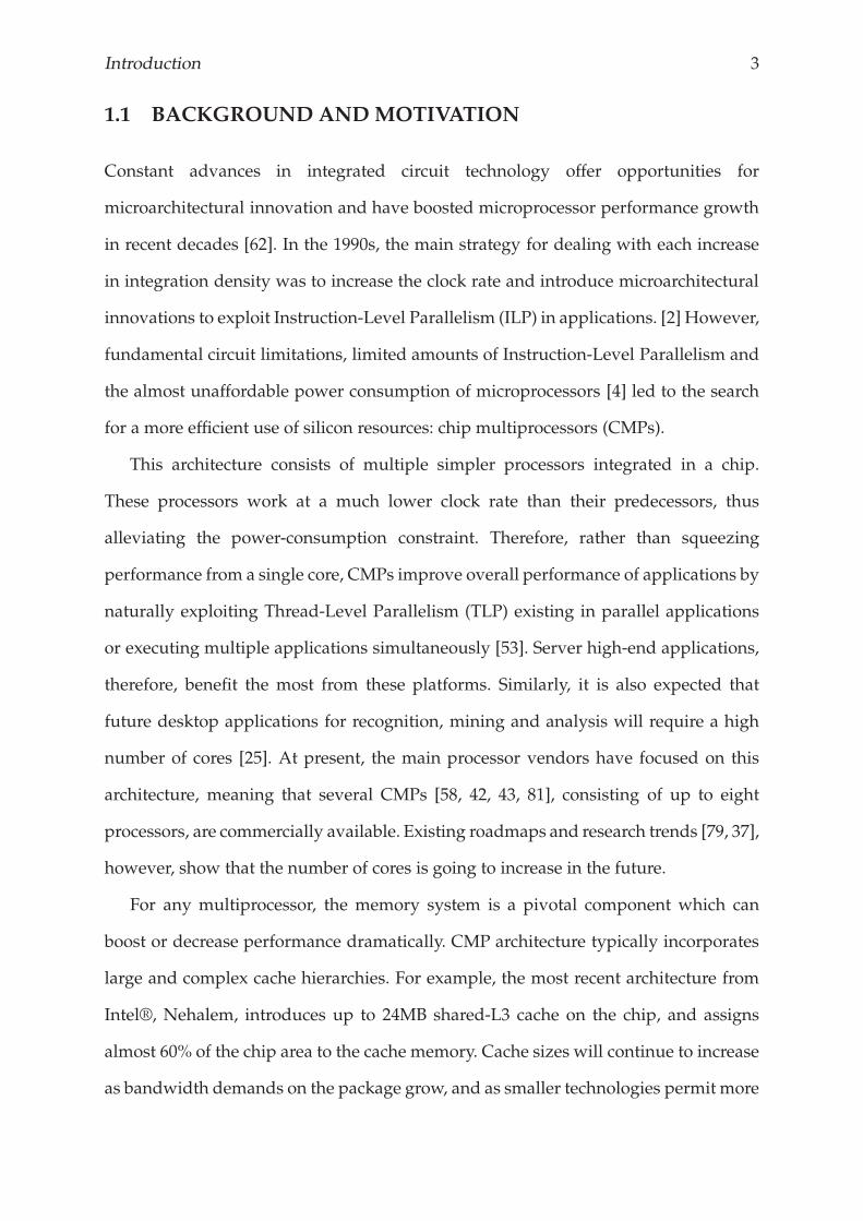
1.1 BACKGROUND ANDMOTIVATION
Constant advances in integrated circuit technology offer opportunities for
microarchitectural innovation and have boosted microprocessor performance growth
in recent decades [62]. In the 1990s, the main strategy for dealing with each increase
in integration density was to increase the clock rate and introduce microarchitectural
innovations to exploit Instruction-Level Parallelism (ILP) in applications. [2] However,
fundamental circuit limitations, limited amounts of Instruction-Level Parallelism and
the almost unaffordable power consumption of microprocessors [4] led to the search
for a more efficient use of silicon resources: chip multiprocessors (CMPs).
This architecture consists of multiple simpler processors integrated in a chip.
These processors work at a much lower clock rate than their predecessors, thus
alleviating the power-consumption constraint. Therefore, rather than squeezing
performance from a single core, CMPs improve overall performance of applications by
naturally exploiting Thread-Level Parallelism (TLP) existing in parallel applications
or executing multiple applications simultaneously [53]. Server high-end applications,
therefore, benefit the most from these platforms. Similarly, it is also expected that
future desktop applications for recognition, mining and analysis will require a high
number of cores [25]. At present, the main processor vendors have focused on this
architecture, meaning that several CMPs [58, 42, 43, 81], consisting of up to eight
processors, are commercially available. Existing roadmaps and research trends [79, 37],
however, show that the number of cores is going to increase in the future.
For any multiprocessor, the memory system is a pivotal component which can
boost or decrease performance dramatically. CMP architecture typically incorporates
large and complex cache hierarchies. For example, the most recent architecture from
Intel®, Nehalem, introduces up to 24MB shared-L3 cache on the chip, and assigns
almost 60% of the chip area to the cache memory. Cache sizes will continue to increase
as bandwidth demands on the package grow, and as smaller technologies permit more
4 Chapter 1.
bits per square milimeter [35]. Researchers from both academia [41] and industry [15]
agree that future CMPs will accommodate large shared on-chip last-level caches.
However, the exponential increase in multicore processor cache sizes accompanied
by growing on-chip wire delays [57] make it difficult to implement traditional caches
with a single and uniform access latency.
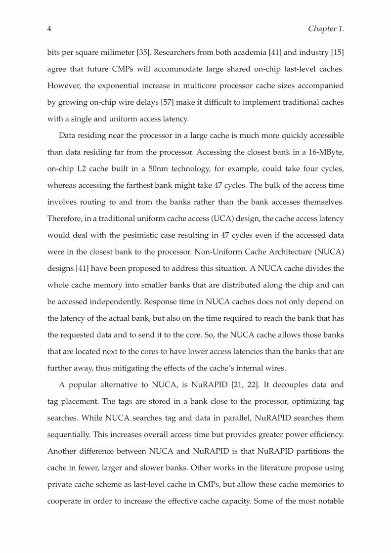
Data residing near the processor in a large cache is much more quickly accessible
than data residing far from the processor. Accessing the closest bank in a 16-MByte,
on-chip L2 cache built in a 50nm technology, for example, could take four cycles,
whereas accessing the farthest bank might take 47 cycles. The bulk of the access time
involves routing to and from the banks rather than the bank accesses themselves.
Therefore, in a traditional uniform cache access (UCA) design, the cache access latency
would deal with the pesimistic case resulting in 47 cycles even if the accessed data
were in the closest bank to the processor. Non-Uniform Cache Architecture (NUCA)
designs [41] have been proposed to address this situation. A NUCA cache divides the
whole cache memory into smaller banks that are distributed along the chip and can
be accessed independently. Response time in NUCA caches does not only depend on
the latency of the actual bank, but also on the time required to reach the bank that has
the requested data and to send it to the core. So, the NUCA cache allows those banks
that are located next to the cores to have lower access latencies than the banks that are
further away, thus mitigating the effects of the cache’s internal wires.
A popular alternative to NUCA, is NuRAPID [21, 22]. It decouples data and
tag placement. The tags are stored in a bank close to the processor, optimizing tag
searches. While NUCA searches tag and data in parallel, NuRAPID searches them
sequentially. This increases overall access time but provides greater power efficiency.
Another difference between NUCA and NuRAPID is that NuRAPID partitions the
cache in fewer, larger and slower banks. Other works in the literature propose using
private cache scheme as last-level cache in CMPs, but allow these cache memories to
cooperate in order to increase the effective cache capacity. Some of the most notable
Introduction 5
of these being cooperative caching [17, 18, 33, 34], victim replication [86], adaptive
selective replication [8] and private/shared cache partitioning scheme [26].
Since their first appearance [41], NUCA caches have been studied and evolved
dealing with the challenges introduced by the improvements in technology, like CMPs
[9, 36]. These works, however, could not exploit the dynamic behaviour of the NUCA
caches on CMPs, and thus, concluded that a simpler static implementation of NUCA
is preferred. Future CMPs will incorporate much larger last-level cache memories on
the chip, and static NUCA approaches that cannot adapt to the application behaviour
will not be convenient in this scenario. In this thesis we propose several techniques to
exploit the dynamic features of NUCA caches for future CMPs.
1.2 NON-UNIFORMCACHE ARCHITECTURES (NUCA)
This thesis proposes several techniques that exploit the non-uniformity provided by
the NUCA caches. This section describes the organization of this kind of cache in the
chip and presents the challenges found with this architecture.
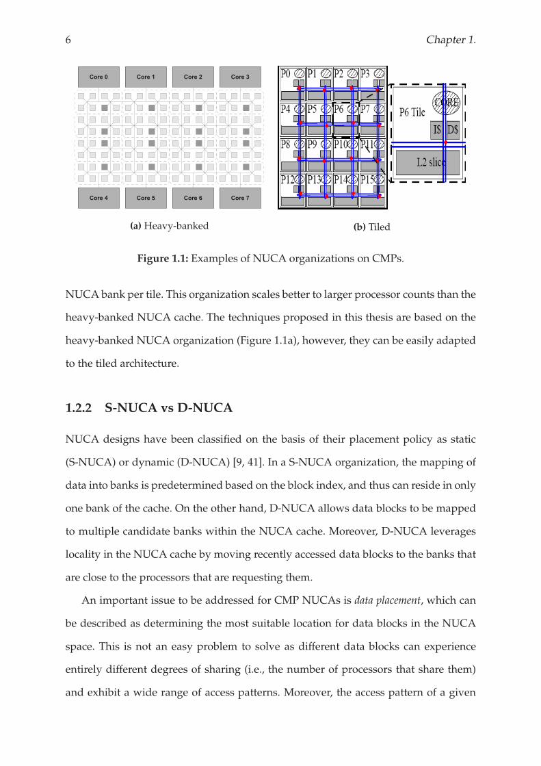
1.2.1 NUCA Organizations
A NUCA cache consists of multple cache banks that work independently from each
other. These are distributed along the chip and interconnected through an on-chip
network. This statement includes lots of possible organizations asNUCA cache. Figure
1.1 shows the two most typical NUCA organizations for CMPs in the literature:
heavy-banked NUCA cache, and the tiled-CMP architecture. The former is usually
located in the center of the chip while the processor cores are in the edges of the shared
cache last-level NUCAcache.Moreover, theNUCA cache in this architecture is splitted
into more, and consequently smaller banks. Cache access latency is smaller with this
organization, however, the challenges in the NUCA cache are harder because there are
more banks to manage. On the other hand, the tiled-CMP architecture implements a
6 Chapter 1.
(a) Heavy-banked (b) Tiled
Figure 1.1: Examples of NUCA organizations on CMPs.
NUCA bank per tile. This organization scales better to larger processor counts than the
heavy-banked NUCA cache. The techniques proposed in this thesis are based on the
heavy-banked NUCA organization (Figure 1.1a), however, they can be easily adapted
to the tiled architecture.
1.2.2 S-NUCA vs D-NUCA
NUCA designs have been classified on the basis of their placement policy as static
(S-NUCA) or dynamic (D-NUCA) [9, 41]. In a S-NUCA organization, the mapping of
data into banks is predetermined based on the block index, and thus can reside in only
one bank of the cache. On the other hand, D-NUCA allows data blocks to be mapped
to multiple candidate banks within the NUCA cache. Moreover, D-NUCA leverages
locality in the NUCA cache by moving recently accessed data blocks to the banks that
are close to the processors that are requesting them.
An important issue to be addressed for CMP NUCAs is data placement, which can
be described as determining the most suitable location for data blocks in the NUCA
space. This is not an easy problem to solve as different data blocks can experience
entirely different degrees of sharing (i.e., the number of processors that share them)
and exhibit a wide range of access patterns. Moreover, the access pattern of a given
Introduction 7
data block can also change during the course of program execution. Therefore a static
placement strategy which fixes the location of each block for the entire application
will perform sub-optimally. D-NUCA, however, allows data to be mapped to multiple
banks within the NUCA cache, and then uses data migration to adapt its placement to
the program behavior as it executes.
D-NUCA promises big benefits by leveraging locality of data in the NUCA cache,
however, none of the previous works in the literature could deal with the challenges
that this configuration introduces. This thesis increases the state-of-art in D-NUCA
management. We deal with the big challenges on D-NUCA and propose techniques
to manage this kind of caches in an efficient way in terms of both performance and
energy consumption.
1.2.3 NUCA Policies
A NUCA cache can be fully characterized by defining the following four policies that
are involved in its behaviour:
• Placement policy: This policy determines where a particular data block can be
mapped in the NUCA cache, as well as its initial location when it arrives from
the off-chip memory.
• Access Policy: This policy determines the search algorithm to follow in order to
find the requested data block in the NUCA cache.
• Replacement Policy: Upon a replacement in a NUCA bank, this policy
determines which data block should be evicted from a particular bank and the
final destination of the evicted data block.
• Migration Policy: Once the data block is in the NUCA cache, the migration
scheme determines its optimal position.
8 Chapter 1.
1.3 CHALLENGES IN DYNAMIC NUCA (D-NUCA)
As previously described, D-NUCA enables data blocks to be mapped in multiple
banks within the NUCA cache, and then uses migration to move these data blocks
to their optimal location. However, the dynamic behaviour and the adaptivity of this
configuration introduce new challenges to the NUCA management. The following
sections present the challenges in D-NUCA classified by the related policy.
1.3.1 Challenges in the Placement Policy
Ideally, a data block would be mapped into any cache bank in order to maximize
placement flexibility. However, the overheads of locating a data block in this scenario
would be too large as each bank would have to be searched, either through a
centralized tag store or by broadcasting the tag to all banks. To address this situation,
NUCA caches implement a set-associative structure along the chip with the cache
banks. Therefore, a data block can only be mapped to a set of banks.
Moreover, advances in technology allows for integrating multiple technologies of
memory into the chip. The most recent processor from IBM®, POWER7, is the first
general-purpose processor that integrates an eDRAM module on the chip [81]. This
could be considered the starting point to integrate more sophisticated hybrid cache
structures on the chip in the near future. In such a case, the placement policy would
be responsible for accomodating multiple technologies in the NUCA cache.
The challenge in the placement policy is to maintain, or even increase, the flexibility
that D-NUCA provides for data to move around the NUCA cache, but keeping
the overheads derived from access and migration policies low. This thesis shows
the implementation of a hybrid NUCA cache. Apart from combining two different
technologies that have different characteristics, this configuration requires to increase
the bank-set associativity in the NUCA cache, and thus increase D-NUCA flexibility
that we mentioned above. We propose a novel placement scheme that accomodates
Introduction 9
both technologies on a single-level of cache and avoids incurring on unaffordable
access overheads that could hurt both performance and energy consumption of the
hybrid scheme.
1.3.2 Challenges in the Access Policy
D-NUCA allows data blocks to be mapped in multiple candidate banks within
the NUCA cache. Because of the migration movements, moreover, data blocks
are constantly changing their location to optimize future accesses. These features
introduce two main challenges on the access scheme: 1) In case of hit in D-NUCA, the
search algorithm may access many NUCA banks before finding the requested data.
If the data is not in the cache, 2) the slowest bank determines the time necessary to
ascertain that the request is a miss.
Prior work shows that implementing a centralized or distributed tag structure
to boost accesses to the NUCA cache in CMP appears to be impractical [9]. Apart
from requiring huge hardware overhead, this tag structure could not be quickly
accessed by all processors due to wire delays, and more importantly, a separate tag
structures would require a complex coherence scheme that updates address location
state with block migrations. Because of that, access schemes in D-NUCA proposed in
the literature follow an algorithmic approach, by accessing the potential locations of
the requested data in parallel, sequentially, or in a particular order.
The biggest challenge in the access policy is to find the requested data block by
introducing the minimum number of messages to the on-chip network. Actually,
several studies have shown the huge performance potential of D-NUCA when using
an oracle as access scheme [9, 36, 41]. In this thesis, we propose an access scheme for
D-NUCA that distributes hints along the NUCA cache. These hints allow our access
scheme to significantly reduce the number of messages introduced to the on-chip
network permemory access, and thus to outperform previously proposed approaches.
10 Chapter 1.
1.3.3 Challenges in the Replacement Policy
D-NUCA provides mechanisms to migrate accessed lines and take them closer to the
core that requested them. Consequently, the most frequently accessed lines are stored
in the banks that are closer to the cores. A replacement in a bank that is close to a
processor, therefore, evicts a line whose probabilities of being accessed farther in the
program aremuch higher than a line from another bank in the NUCAcache.Moreover,
as banks in the NUCA cache work independently of each other, none of the less used
banks can even know that a particular bank is constantly evicting data blocks that are
being reused.
The challenge in the replacement policy is to globalize replacements that happen in
a particular bank, in order to find the most approppriate data to evict from the whole
NUCA cache. Unfortunately, most previous works have ignored the replacement
issue or have adopted a replacement scheme that was originally designed for use
in uniprocessors/uniform-caches. In this thesis, we propose an adaptive replacement
framework that effectively globalizes replacement decisions taken in a particular bank
to the whole NUCA cache.
1.3.4 Challenges in the Migration Policy
Determining the best location for a particular data block is the big challenge in the
migration policy. Data blocks that are accessed by only one processor core tend to
move to the closest bank to the requesting core. However, determining the most
optimal location for a shared data block is not so obvious. Prior research on D-NUCA
has developed two main trends for dealing with data migration: 1) promotion
and 2) optimal position. With promotion [9, 23, 41] the requested data is moved
closer to the processor that initiated the memory request upon a hit in the NUCA
cache. This scheme is especially effective in uniprocessor systems. However, in a
CMP environment, multiple processors accessing shared data results in this data
Introduction 11
“ping-ponging” between NUCA banks. Other migration schemes in the literature
compute the optimal placement for a particular data block by taking into consideration
dynamic parameters such as the usage of data or the processors that are currently
sharing it [31, 39]. These schemes effectively reduce the ping-pong effect at the cost
of significantly increasing complexity. Moreover, these approaches do not provide
minimum access latency for shared data.
A perfect migration policy would move data blocks in such a way that given a hit
in the NUCA cache it will happen in the closest bank to the requesting core. So, the
challenge in the migration policy is to be as close as possible to this situation. In this
thesis, we propose anticipatingmigration movements based on history patterns. Using
our mechanism, D-NUCA takes optimal cache access latency to response memory
requests to data blocks that were far from the requesting core in other case.
1.4 MAIN CONTRIBUTIONS
This thesis proposes several techniques to deal with the challenges introduced by
D-NUCA caches on CMPs. First of all, we studied the behaviour of a D-NUCA
cache on a CMP in terms of performance and energy consumption. We analyzed
the state-of-art of D-NUCA management and identified the main challenges related
to each NUCA policy. Based on these results, we focused on improving D-NUCA
management from the point of view of the four NUCA policies.
The analysis of the NUCA policies has been firstly presented in the 2nd Workshop
on Managed Multi-Core Systems (MMCS’09) [47]. An extended version of this analysis
has also been published in the Proceedings of the XX Jornadas de Paralelismo [50].
1.4.1 Replacement policy
We propose three techniques to deal with the replacement issue in D-NUCA caches.
• We first propose the Last Bank. This introduces an extra bank in the D-NUCA
12 Chapter 1.
that acts as victim cache by catching evicted data blocks from the NUCA cache.
This work has been published in the Proceedings of the 15th International Euro-Par
Conference (Euro-Par’09) [48].
• Then, we propose modifying the traditional LRU replacement policy to deal with
D-NUCA features, like data migration. This results on LRU-PEA, a replacement
policy that prioritizes data blocks stored in the NUCA cache relying on the their
last migration action.
LRU-PEA has been published in the Proceedings of the 27th IEEE International
Conference on Computer Design (ICCD’09) [49].
• Finally, we propose The Auction. This is an adaptive framework to implement
replacement policies for D-NUCA caches. This globalizes replacement decisions
taken in a particular bank to the whole NUCA cache. Using this scheme,
therefore, the replacement policy picks the most approppriate data block to be
evicted, not only from the particular bank where the replacement is happenning,
but from the whole NUCA cache.
The Auction has been published in the Proceedings of the 24th International
Conference on Supercomputing (ICS’10) [51].
1.4.2 Access policy
In order to tackle the challenges with the access scheme in D-NUCA cache memories,
we propose HK-NUCA. This technique provides to the NUCA banks information
about the chunk of data blocks that would be statically mapped in them. By using
this information, HK-NUCA significantly reduces the number of messages required
to satisfy a memory request, and reduces the miss resolution time of the NUCA cache.
HK-NUCA has been published in the Proceedings of the 25th IEEE International
Parallel and Distributed Processing Symposium (IPDPS’11) [52].
Introduction 13
1.4.3 Placement policy
The implementation of a hybrid NUCA cache introduces several challenges to the
NUCA cache. We propose a novel placement scheme that accomodates two different
technologies, SRAM and eDRAM, in a D-NUCA cache. We show that efficiently
managing data placement, our hybrid NUCA cache succeeds in emphasizing the
strengths of each technology, and hiding their drawbacks.
This work has been published in the Proceedings of the 18th Annual International
Conference on High Performance Computing (HiPC’11) [46].
1.4.4 Migration policy
We propose The Migration Prefetcher. This technique recognizes access patterns, and
then, anticipates data migration. Using this mechanism, the D-NUCA cache can take
the optimal response time (i.e. when the data block is stored in the closest bank to the
requesting processor) for satisfying a request for a data which is the farthest bank.
The Migration Prefetcher has been published in the Proceedings of the 20th
International Conference on Parallel Architectures and Compilation Techniques (PACT’11)
[45].
1.5 DOCUMENT ORGANIZATION
The remainder of this dissertation is structured as follows:
• Chapter 2 describes the baseline architecture, as well as the experimental
methodology followed in this thesis.
• Chapter 3 presents the techniques proposed to deal with the issues related with
the replacement policy.
• Chapter 4 describes HK-NUCA, the technique proposed in this thesis to tackle
with the access issues in D-NUCA.
14 Chapter 1.
• Chapter 5 shows the implementation of a hybrid NUCA cache, and describes the
placement policy assumed.
• Chapter 6 presents The Migration Prefetcher.
• Chapter 7 concludes this thesis and outlines the future work.
Chapter 2
Experimental framework
This chapter describes the baseline configuration and the experimental framework used in this
thesis.

Experimental framework 17
This chapter describes the experimental framework and the methodology used
in this thesis. First, Section 2.1 describes the baseline configuration assumed in the
remainder of the thesis, and then, the experimental methodology is described in
Section 2.2.
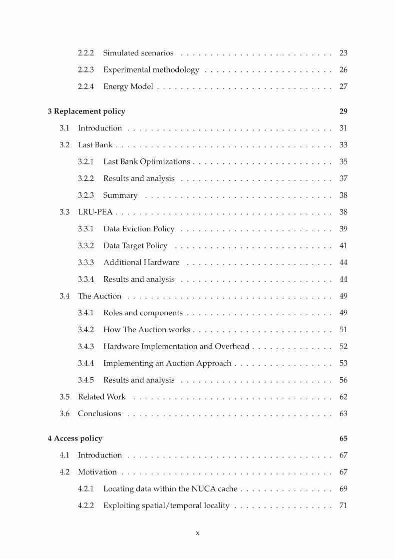
2.1 BASELINE NUCA CACHE ARCHITECTURE
We assume an inclusive totally-shared L2 cache with a Non-Uniform Cache
Architecture (NUCA), derived from the Dynamic NUCA (D-NUCA) design by
Kim et al. [41]. As in the original proposal we partition the address space across cache
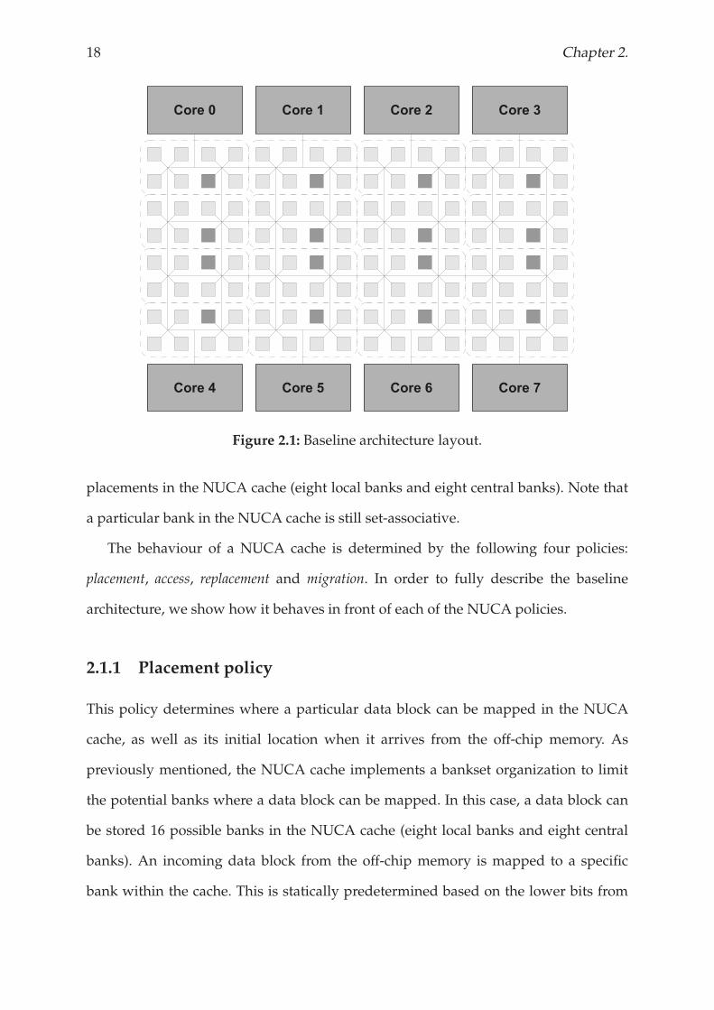
banks which are connected via a 2D mesh interconnection network. As illustrated in
Figure 2.1, the NUCA storage is partitioned into 128 banks. D-NUCA allowsmigration
of data towards the cores that use it the most. This distributes data blocks among the
NUCA banks so data close to the cores is accessed the most often, thus reducing the
access latency for future accesses to the same data.
Ideally, a data block would be mapped into any cache bank in order to maximize
placement flexibility. However, the overheads of locating a data block in this scenario
would be too large as each bank would have to be searched, either through a
centralized tag store or by broadcasting the tag to all banks. Tomitigate this, theNUCA
cache is treated as a set-associative structure, called banksets, with each bank holding
one “way” of the set. Thus, data blocks can be mapped to any bank within a single
bankset. The NUCA banks that make up a bankset are organized into bankclusters
within the cache (the dotted boxes in Figure 2.1). Each bankcluster consists of a
single bank from each bankset. As an example, the darker NUCA banks in Figure
2.1 compose a bankset. As shown in Figure 2.1, we assume a NUCA cache that is
16-way bankset associative, organized in 16 bankclusters. The eight bankclusters that
are located close to the cores compose the local banks, and the other eight in the
center of the NUCA cache are the central banks. Therefore, a data block has 16 possible
18 Chapter 2.
Figure 2.1: Baseline architecture layout.
placements in the NUCA cache (eight local banks and eight central banks). Note that
a particular bank in the NUCA cache is still set-associative.
The behaviour of a NUCA cache is determined by the following four policies:
placement, access, replacement and migration. In order to fully describe the baseline
architecture, we show how it behaves in front of each of the NUCA policies.
2.1.1 Placement policy
This policy determines where a particular data block can be mapped in the NUCA
cache, as well as its initial location when it arrives from the off-chip memory. As
previously mentioned, the NUCA cache implements a bankset organization to limit
the potential banks where a data block can be mapped. In this case, a data block can
be stored 16 possible banks in the NUCA cache (eight local banks and eight central
banks). An incoming data block from the off-chip memory is mapped to a specific
bank within the cache. This is statically predetermined based on the lower bits from
Experimental framework 19
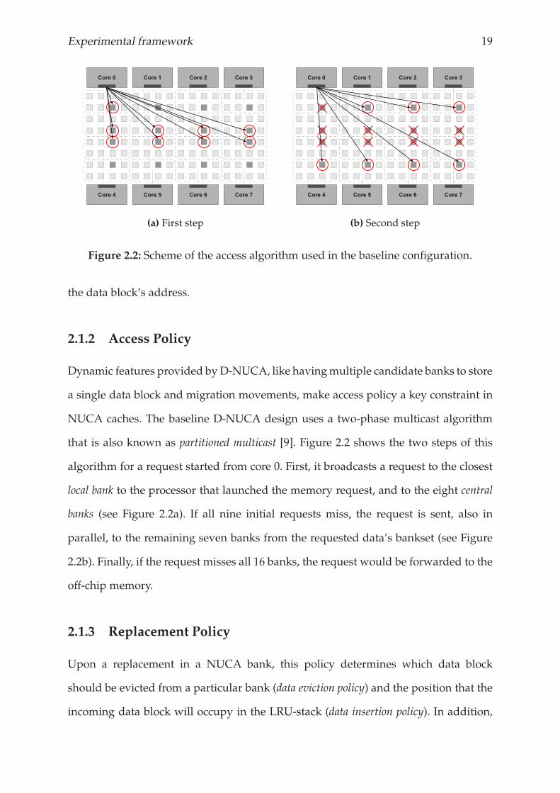
(a) First step (b) Second step
Figure 2.2: Scheme of the access algorithm used in the baseline configuration.
the data block’s address.
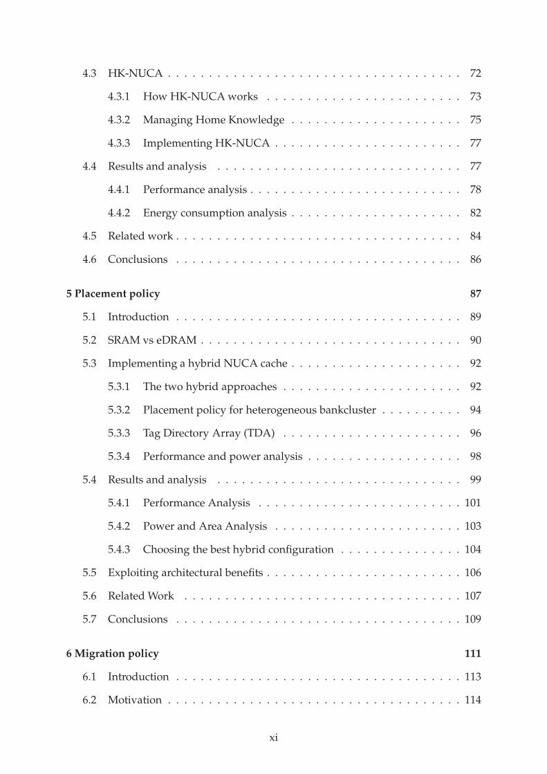
2.1.2 Access Policy
Dynamic features provided byD-NUCA, like havingmultiple candidate banks to store
a single data block and migration movements, make access policy a key constraint in
NUCA caches. The baseline D-NUCA design uses a two-phase multicast algorithm
that is also known as partitioned multicast [9]. Figure 2.2 shows the two steps of this
algorithm for a request started from core 0. First, it broadcasts a request to the closest
local bank to the processor that launched the memory request, and to the eight central
banks (see Figure 2.2a). If all nine initial requests miss, the request is sent, also in
parallel, to the remaining seven banks from the requested data’s bankset (see Figure
2.2b). Finally, if the request misses all 16 banks, the request would be forwarded to the
off-chip memory.
2.1.3 Replacement Policy
Upon a replacement in a NUCA bank, this policy determines which data block
should be evicted from a particular bank (data eviction policy) and the position that the
incoming data block will occupy in the LRU-stack (data insertion policy). In addition,
20 Chapter 2.
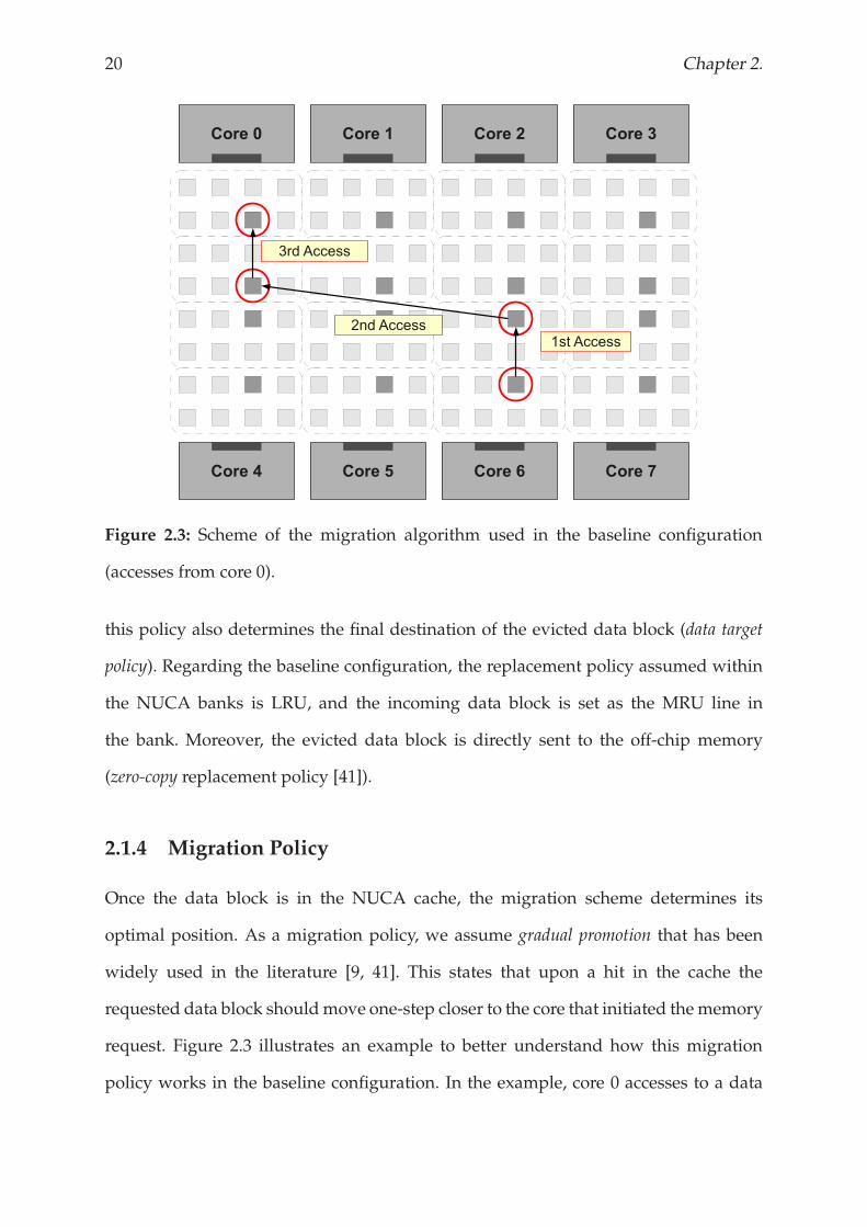
Figure 2.3: Scheme of the migration algorithm used in the baseline configuration
(accesses from core 0).
this policy also determines the final destination of the evicted data block (data target
policy). Regarding the baseline configuration, the replacement policy assumed within
the NUCA banks is LRU, and the incoming data block is set as the MRU line in
the bank. Moreover, the evicted data block is directly sent to the off-chip memory
(zero-copy replacement policy [41]).
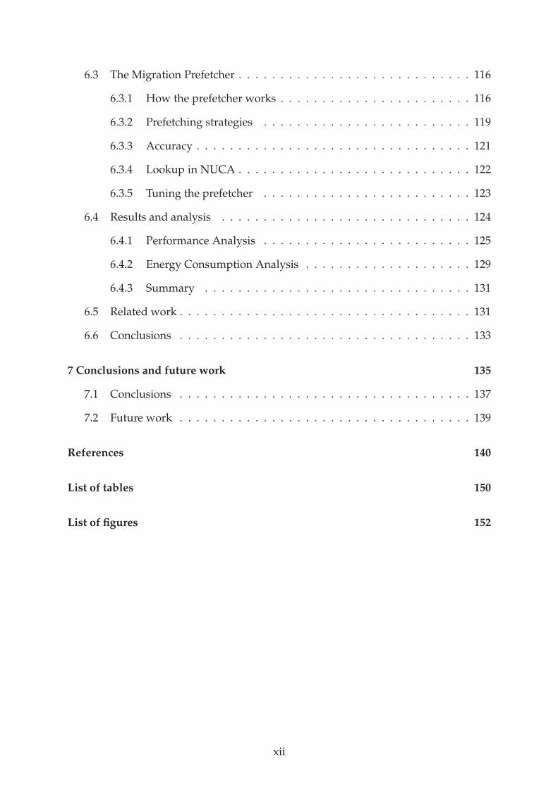
2.1.4 Migration Policy
Once the data block is in the NUCA cache, the migration scheme determines its
optimal position. As a migration policy, we assume gradual promotion that has been
widely used in the literature [9, 41]. This states that upon a hit in the cache the
requested data block shouldmove one-step closer to the core that initiated thememory
request. Figure 2.3 illustrates an example to better understand how this migration
policy works in the baseline configuration. In the example, core 0 accesses to a data
Experimental framework 21
block which is stored in the local bank of the core 6 (this is the most pessimistic
situation). Then, the requested data block moves one-step towards the requesting core,
and thus stays in a central bank near the core 6. After the core 0 accesses to the same
data block for the second time, it leaves core 6 influence area, and arrives to the central
bank of core 0. If the same data is accessed again by the core 0, it promotes towards
the core 0 arriving to the optimal location in terms of access latency for accesses from
the core 0.
2.2 METHODOLOGY AND EXPERIMENTAL FRAMEWORK
2.2.1 Simulation tools
This section presents the simulators that have been used in the studies performed in
this thesis.
Simics
Simics [55] was originally developed by the Sweedish Institute of Computer Science
(SICS), and the spun off to Virtutech for commercial development in 1998. This
company has been recently acquired by Intel Corporation. Simics is a full-system
simulator that simulates processors at the instruction-set level, including the full
supervisor state. It currently supports models for the following architectures:
UltraSPARC, Alpha, x86, x86-64 (Hammer), PowerPC, IPF (Itanium), MIPS, and ARM.
In addition to the ability of simulating target architectures, Simics easily allows
the inclusion of extensions or modules in order to extend its functionalities. Our
simulation environment includes Ruby, that is a Simics extension that provides a
highly-detailed timing simulator for memory systems. Ruby is part of the GEMS
toolset.
22 Chapter 2.
GEMS
General Execution-driven Multiprocessor Simulator (GEMS) [56] is a set of
modules for Simics that enables detailed simulation of multiprocessor systems.
It was developed by the Wisconsin Multifacet Project at the University of
Wisconsin-Madison. GEMS consists of three modules for Simics, but only one of
them (Ruby) participates in the simulation environment assumed in this thesis. The
other modules are Opal and Tourmaline, which provide support for out-of-order
computation and transactional memory, respectively.
Ruby is a timing simulator for multiprocessor memory system. It provides support
for modeling at high-level of detail any memory component, like cache memories,
cache controllers, network-on-chip, memory controllers, or banks of memory. The
flexibility of Ruby, moreover, allows for implementing more sophisticated cache
designs like D-NUCA architectures. Ruby also incorporates other simulators to extend
its functionalities like Garnet [1] andOrion [80]. Garnet provides amore realistic vision
of the on-chip network, whereas Orion is a power simulator.
CACTI
CACTI [83] is an integrated cache access time, cycle time, area, leakage, and dynamic
power model tool. By integrating all of these models in a single tool, users can be
confident that trade-offs between time, power and area are all based on the same
assumptions.
Since 1994, when CACTI was first released, six major versions have been released
introducing new features which deal with the current technology requirements. The
most recent release of CACTI, which is the version 6.0 [64, 65] and was released in
2007, provides support to deal with large cache architectures that are influenced by
wire delays, like NUCA caches. In Chapter 5, we also use CACTI 5.1 [76] to model
cache memories implemented with eDRAM technology.
Experimental framework 23
2.2.2 Simulated scenarios
In order to evaluate every technique proposed in this thesis, we have assumed two
different scenarios: 1) Multi-programmed and 2) Parallel applications. The former
executes a set of eight different SPEC CPU2006 [11] workloads with the reference input
in parallel. The latter simulates the whole set of applications from the PARSEC v2.0
benchmark suite [12] with the simlarge input data sets.
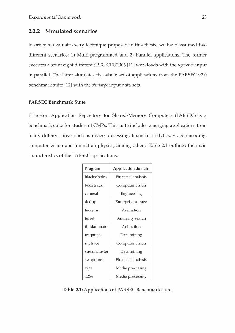
PARSEC Benchmark Suite
Princeton Application Repository for Shared-Memory Computers (PARSEC) is a
benchmark suite for studies of CMPs. This suite includes emerging applications from
many different areas such as image processing, financial analytics, video encoding,
computer vision and animation physics, among others. Table 2.1 outlines the main
characteristics of the PARSEC applications.
Program Application domain
blackscholes Financial analysis
bodytrack Computer vision
canneal Engineering
dedup Enterprise storage
facesim Animation
ferret Similarity search
fluidanimate Animation
freqmine Data mining
raytrace Computer vision
streamcluster Data mining
swaptions Financial analysis
vips Media processing
x264 Media processing
Table 2.1: Applications of PARSEC Benchmark siute.
24 Chapter 2.
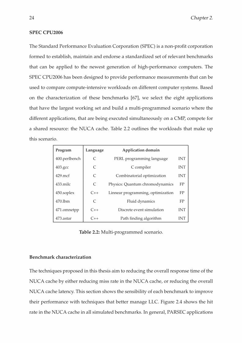
SPEC CPU2006
The Standard Performance Evaluation Corporation (SPEC) is a non-profit corporation
formed to establish, maintain and endorse a standardized set of relevant benchmarks
that can be applied to the newest generation of high-performance computers. The
SPEC CPU2006 has been designed to provide performance measurements that can be
used to compare compute-intensive workloads on different computer systems. Based
on the characterization of these benchmarks [67], we select the eight applications
that have the largest working set and build a multi-programmed scenario where the
different applications, that are being executed simultaneously on a CMP, compete for
a shared resource: the NUCA cache. Table 2.2 outlines the workloads that make up
this scenario.
Program Language Application domain
400.perlbench C PERL programming language INT
403.gcc C C compiler INT
429.mcf C Combinatorial optimization INT
433.milc C Physics: Quantum chromodynamics FP
450.soplex C++ Linnear programming, optimization FP
470.lbm C Fluid dynamics FP
471.omnetpp C++ Discrete event simulation INT
473.astar C++ Path finding algorithm INT
Table 2.2: Multi-programmed scenario.
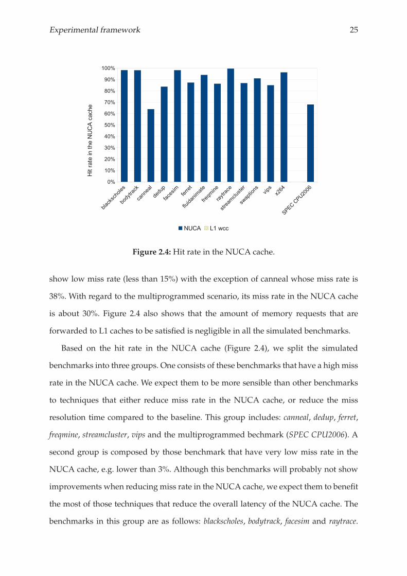
Benchmark characterization
The techniques proposed in this thesis aim to reducing the overall response time of the
NUCA cache by either reducing miss rate in the NUCA cache, or reducing the overall
NUCA cache latency. This section shows the sensibility of each benchmark to improve
their performance with techniques that better manage LLC. Figure 2.4 shows the hit
rate in the NUCA cache in all simulated benchmarks. In general, PARSEC applications
Experimental framework 25
Figure 2.4:Hit rate in the NUCA cache.
show low miss rate (less than 15%) with the exception of canneal whose miss rate is
38%. With regard to the multiprogrammed scenario, its miss rate in the NUCA cache
is about 30%. Figure 2.4 also shows that the amount of memory requests that are
forwarded to L1 caches to be satisfied is negligible in all the simulated benchmarks.
Based on the hit rate in the NUCA cache (Figure 2.4), we split the simulated
benchmarks into three groups. One consists of these benchmarks that have a highmiss
rate in the NUCA cache. We expect them to be more sensible than other benchmarks
to techniques that either reduce miss rate in the NUCA cache, or reduce the miss
resolution time compared to the baseline. This group includes: canneal, dedup, ferret,
freqmine, streamcluster, vips and the multiprogrammed bechmark (SPEC CPU2006). A
second group is composed by those benchmark that have very low miss rate in the
NUCA cache, e.g. lower than 3%. Although this benchmarks will probably not show
improvements when reducing miss rate in the NUCA cache, we expect them to benefit
the most of those techniques that reduce the overall latency of the NUCA cache. The
benchmarks in this group are as follows: blackscholes, bodytrack, facesim and raytrace.
26 Chapter 2.
Finally, the third group includes the other benchmarks (fluidanimate, swaptions and
x264). The hit rate in the NUCA cache of the benchmarks in this group stay in the
middle of the other groups. We expect these benchmarks to obtain some performance
improvements with either techniques that reduce miss rate or reduce the overall
NUCA latency.
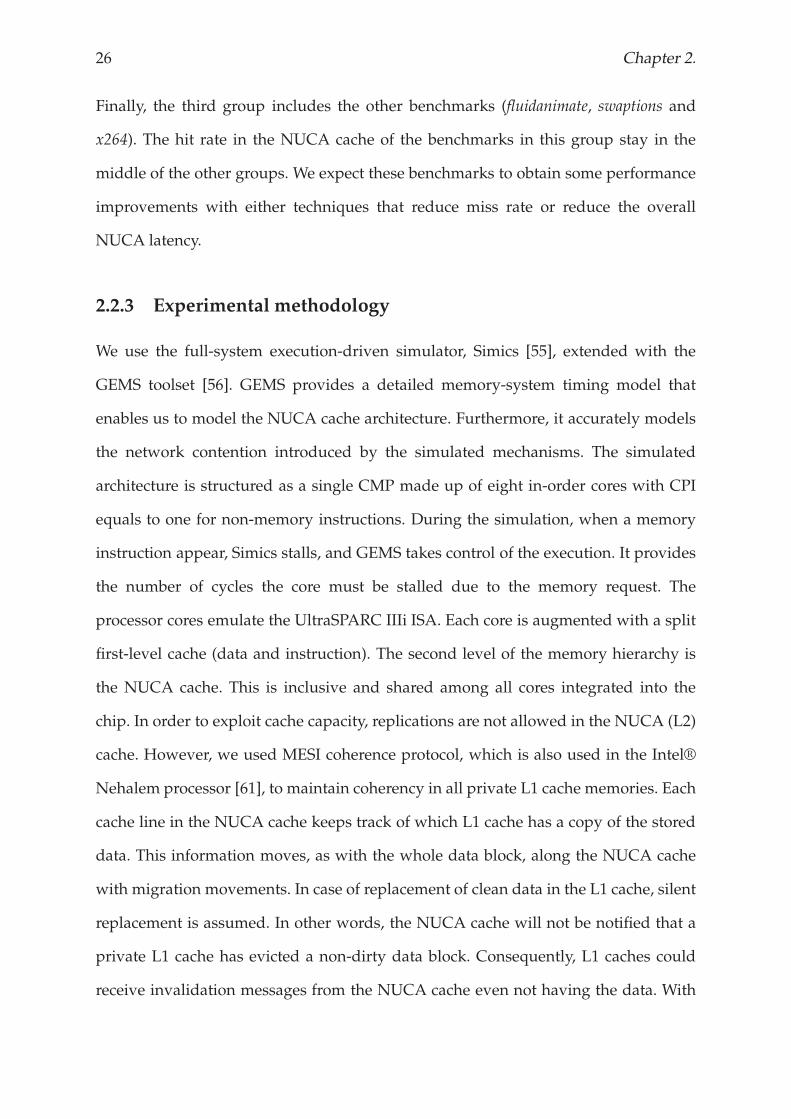
2.2.3 Experimental methodology
We use the full-system execution-driven simulator, Simics [55], extended with the
GEMS toolset [56]. GEMS provides a detailed memory-system timing model that
enables us to model the NUCA cache architecture. Furthermore, it accurately models
the network contention introduced by the simulated mechanisms. The simulated
architecture is structured as a single CMP made up of eight in-order cores with CPI
equals to one for non-memory instructions. During the simulation, when a memory
instruction appear, Simics stalls, and GEMS takes control of the execution. It provides
the number of cycles the core must be stalled due to the memory request. The
processor cores emulate the UltraSPARC IIIi ISA. Each core is augmented with a split
first-level cache (data and instruction). The second level of the memory hierarchy is
the NUCA cache. This is inclusive and shared among all cores integrated into the
chip. In order to exploit cache capacity, replications are not allowed in the NUCA (L2)
cache. However, we used MESI coherence protocol, which is also used in the Intel®
Nehalem processor [61], to maintain coherency in all private L1 cache memories. Each
cache line in the NUCA cache keeps track of which L1 cache has a copy of the stored
data. This information moves, as with the whole data block, along the NUCA cache
with migration movements. In case of replacement of clean data in the L1 cache, silent
replacement is assumed. In other words, the NUCA cache will not be notified that a
private L1 cache has evicted a non-dirty data block. Consequently, L1 caches could
receive invalidation messages from the NUCA cache even not having the data. With
Experimental framework 27
regard to the memory consistency model, we assume sequential consistency.
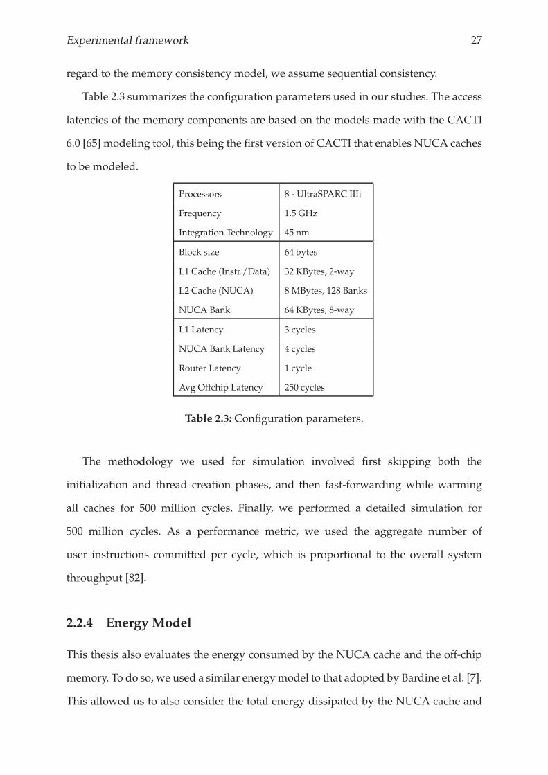
Table 2.3 summarizes the configuration parameters used in our studies. The access
latencies of the memory components are based on the models made with the CACTI
6.0 [65] modeling tool, this being the first version of CACTI that enables NUCA caches
to be modeled.
Processors 8 - UltraSPARC IIIi
Frequency 1.5 GHz
Integration Technology 45 nm
Block size 64 bytes
L1 Cache (Instr./Data) 32 KBytes, 2-way
L2 Cache (NUCA) 8 MBytes, 128 Banks
NUCA Bank 64 KBytes, 8-way
L1 Latency 3 cycles
NUCA Bank Latency 4 cycles
Router Latency 1 cycle
Avg Offchip Latency 250 cycles
Table 2.3: Configuration parameters.
The methodology we used for simulation involved first skipping both the
initialization and thread creation phases, and then fast-forwarding while warming
all caches for 500 million cycles. Finally, we performed a detailed simulation for
500 million cycles. As a performance metric, we used the aggregate number of
user instructions committed per cycle, which is proportional to the overall system
throughput [82].
2.2.4 Energy Model
This thesis also evaluates the energy consumed by the NUCA cache and the off-chip
memory. To do so, we used a similar energymodel to that adopted by Bardine et al. [7].
This allowed us to also consider the total energy dissipated by the NUCA cache and
28 Chapter 2.
the additional energy required to access the off-chip memory. The energy consumed
by the memory system is computed as follows:
Etotal = Estatic + Edynamic
Estatic = ES_noc + ES_banks + ES_mechanism
Edynamic = ED_noc + ED_banks + ED_mechanism + Eoff−chip
We usedmodels provided by CACTI [76, 64] to evaluate static energy consumed by
the memory structures (ES_banks and ES_mechanism). CACTI has been used to evaluate
dynamic energy consumption as well, but GEMS [56] support is required in this case
to ascertain the dynamic behavior in the applications (ED_banks and ED_mechanism).
GEMS also contains an integrated power model based on Orion [80] that we used
to evaluate the static and dynamic power consumed by the on-chip network (ES_noc
and ED_noc). Note that the extra messages introduced by the mechanism that is being
evaluated into the on-chip network are accurately modeled by the simulator. The
energy dissipated by the off-chip memory (Eoff−chip) was determined using theMicron
System Power Calculator [60] assuming a modern DDR3 system (4GB, 8DQs, Vdd:1.5v,
333 MHz). Our evaluation of the off-chip memory focused on the energy dissipated
during active cycles and isolated this from the background energy. This study shows
that the average energy of each access is 550 pJ.
As an energy metric we used the energy consumed per memory access. This
is based on the energy per instruction (EPI) [29] metric which is commonly used
for analysing the energy consumed by the whole processor. This metric works
independently of the amount of time required to process an instruction and is ideal
for throughput performance.
Chapter 3
Replacement policy
The decentralized nature of NUCA prevents the replacement policies proposed in the literature
from being effective for this kind of caches. As banks operate independently from each other,
their replacement decisions are restricted to a single NUCA bank. This chapter presents three
approaches for effectively dealing with replacements in NUCA caches.

Replacement policy 31
3.1 INTRODUCTION
NUCA caches provide mechanisms to migrate accessed lines and take them closer
to the core that requested them. Consequently, the most frequently accessed lines are
stored in the banks that are closer to the cores, which we call hot banks. A replacement
in a hot bank, however, evicts a line whose probabilities of being accessed farther in
the program are much higher than a line from another bank in the NUCA cache.
Moreover, as banks in the NUCA cache work independently of each other, none of the
less used banks can even know that a hot bank is constantly evicting data blocks that are
being reused. Thus, a more sophisticated replacement policy that allows all banks in the
NUCA cache to take part in data-replacement decisions is desirable. Insofar evicted
lines from the hot banks can be relocated to other banks in the NUCA cache, instead
of being evicted from the NUCA cache permanently. Unfortunately, most previous
works have ignored the replacement issue or have adopted a replacement scheme that
was originally designed for use in uniprocessors/uniform-caches.
Kim et al. [41] proposed two replacement policies for NUCA caches in a
uniprocessor environment: zero-copy and one-copy policies. The evicted line in the
NUCA cache, assuming the zero-copy policy, is sent back to the upper level of the
memory hierarchy (the main memory in our studies). If the one-copy policy is adopted,
however, the evicted line is demoted to a more distant bank. This policy gives a second
chance to the evicted lines to stay within the NUCA cache. In order to evaluate these
schemes, we have adapted them for CMP. Our version of the one-copy policy for CMP
gives a second chance to the evicted lines by randomly relocating them to a bank from
the bankset where they can be mapped.
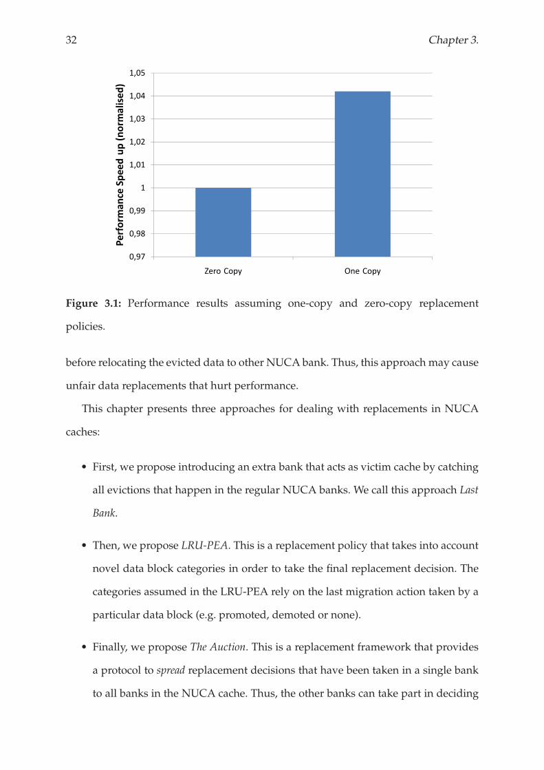
Figure 3.1 shows that, the one-copy replacement policy improves performance
compared to the baseline configuration1. One-copy, however, is considered as a blind
replacement policy, insofar as it does not take into account the current cache state
1The experimental methodology is described in Section 2.2.
32 Chapter 3.
1,04
1,05
sed)
1,03
,
orm
alis
1,02
dup(no
1
1,01
eSpeed
0,99
rmance
0,98
Perfor
0,97
Zero Copy One Copy
Figure 3.1: Performance results assuming one-copy and zero-copy replacement
policies.
before relocating the evicted data to other NUCA bank. Thus, this approach may cause
unfair data replacements that hurt performance.
This chapter presents three approaches for dealing with replacements in NUCA
caches:
• First, we propose introducing an extra bank that acts as victim cache by catching
all evictions that happen in the regular NUCA banks. We call this approach Last
Bank.
• Then, we propose LRU-PEA. This is a replacement policy that takes into account
novel data block categories in order to take the final replacement decision. The
categories assumed in the LRU-PEA rely on the last migration action taken by a
particular data block (e.g. promoted, demoted or none).
• Finally, we propose The Auction. This is a replacement framework that provides
a protocol to spread replacement decisions that have been taken in a single bank
to all banks in the NUCA cache. Thus, the other banks can take part in deciding
Replacement policy 33
which is the most appropriate data to evict within the whole NUCA cache.
The remainder of this chapter is structured as follows. Section 3.2 presents the Last
Bank approach. Section 3.3 describes and analyses the LRU-PEA replacement policy. In
Section 3.4, we describe The Auction framework. Related work is discussed in Section
3.5, and concluding remarks are given in Section 3.6.
3.2 LAST BANK
Cache memories take advantage of the temporal and spatial data locality that
applications usually exhibit. However, the whole working set does not usually fit into
the cache memory, causing capacity and conflict misses. These misses mean that a line
that may be accessed later has to leave the cache prematurely. As a result, evicted lines
that are later reused return to the cache memory in a short period of time. This is more
pronounced in a NUCA cache memory because data movements within the cache
are allowed, so the most recently accessed data blocks are concentrated in few banks
rather than evenly spread over the entire cachememory. Therefore, we propose adding
an extra bank to deal with data blocks that have been evicted from the NUCA cache,
and acts as a victim cache [38]. This extra bank, called Last Bank, provides evicted data
blocks a second chance to come back to the NUCA cache without leaving the chip.
Last Bank, which is as large as a single bank in the NUCA cache, acts as the
last-level cache between the NUCA cache and the off-chip memory. It is physically
located in the center of the chip at about the same distance to all cores. When there
is a hit on Last Bank, the accessed data block leaves the Last Bank and returns to the
corresponding bank in the NUCA cache.
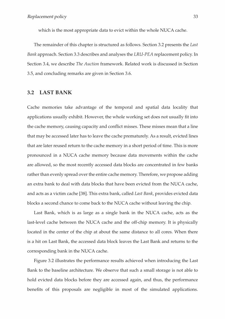
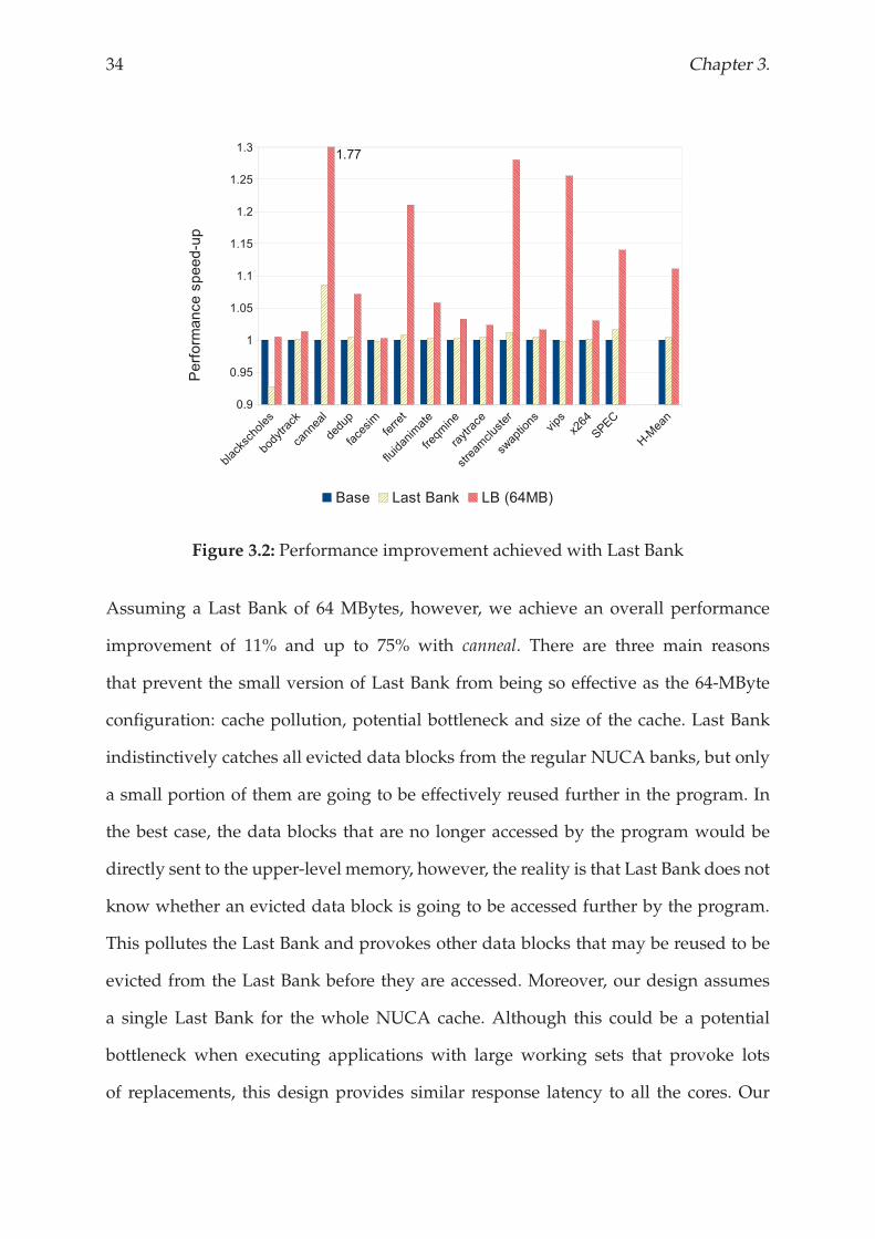
Figure 3.2 illustrates the performance results achieved when introducing the Last
Bank to the baseline architecture. We observe that such a small storage is not able to
hold evicted data blocks before they are accessed again, and thus, the performance
benefits of this proposals are negligible in most of the simulated applications.
34 Chapter 3.
Figure 3.2: Performance improvement achieved with Last Bank
Assuming a Last Bank of 64 MBytes, however, we achieve an overall performance
improvement of 11% and up to 75% with canneal. There are three main reasons
that prevent the small version of Last Bank from being so effective as the 64-MByte
configuration: cache pollution, potential bottleneck and size of the cache. Last Bank
indistinctively catches all evicted data blocks from the regular NUCA banks, but only
a small portion of them are going to be effectively reused further in the program. In
the best case, the data blocks that are no longer accessed by the program would be
directly sent to the upper-level memory, however, the reality is that Last Bank does not
know whether an evicted data block is going to be accessed further by the program.
This pollutes the Last Bank and provokes other data blocks that may be reused to be
evicted from the Last Bank before they are accessed. Moreover, our design assumes
a single Last Bank for the whole NUCA cache. Although this could be a potential
bottleneck when executing applications with large working sets that provoke lots
of replacements, this design provides similar response latency to all the cores. Our
Replacement policy 35
evaluation also shows that a Last Bank of 64 KBytes is not large enough to hold all
evictions from 128 NUCA banks, thus we conclude that the benefits of this approach
are limited by the size of the Last Bank.
3.2.1 Last Bank Optimizations
This section describes two optimizations for the Last Bank approach. They exploit
some of the drawbacks of these mechanism and allows it to achieve higher
performance benefits at low implementation cost.
Selective Last Bank
Last Bank is not large enough to deal with all the evicted data blocks from the entire
NUCA cache. So, Last Bank is polluted with useless data blocks that will not be
accessed again and that provoke the eviction of useful data blocks from Last Bank
before they are accessed. This fact leads us to propose a selection mechanism in Last
Bank called Selective Last Bank. This selection mechanism allows evicted data blocks
to be inserted into Last Bank by way of a filter. The aim is to prevent Last Bank from
becoming polluted with data blocks that are not going to be accessed further by the
program.
Migration movements in D-NUCA cache make most accessed data blocks to
concentrate in the NUCA banks that are close to the cores (local banks). Consequently,
the probabilities of a data block that have been evicted from a local bank to return to
theNUCA cache are much higher than if it were evicted from a central bank. Therefore,
we propose a filter that allows only the evicted data blocks that resided in a local bank
before eviction to be cached.
36 Chapter 3.
(a) (b) (c)
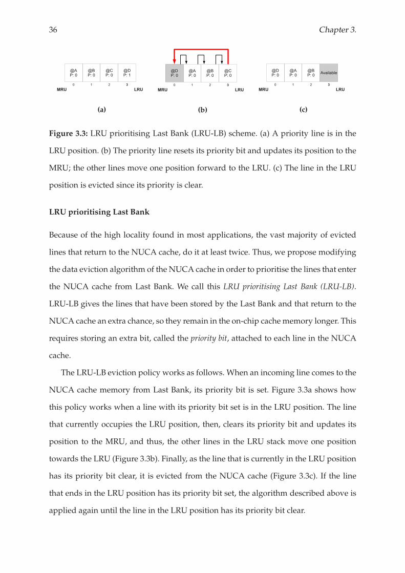
Figure 3.3: LRU prioritising Last Bank (LRU-LB) scheme. (a) A priority line is in the
LRU position. (b) The priority line resets its priority bit and updates its position to the
MRU; the other lines move one position forward to the LRU. (c) The line in the LRU
position is evicted since its priority is clear.
LRU prioritising Last Bank
Because of the high locality found in most applications, the vast majority of evicted
lines that return to the NUCA cache, do it at least twice. Thus, we propose modifying
the data eviction algorithm of the NUCA cache in order to prioritise the lines that enter
the NUCA cache from Last Bank. We call this LRU prioritising Last Bank (LRU-LB).
LRU-LB gives the lines that have been stored by the Last Bank and that return to the
NUCA cache an extra chance, so they remain in the on-chip cachememory longer. This
requires storing an extra bit, called the priority bit, attached to each line in the NUCA
cache.
The LRU-LB eviction policy works as follows. When an incoming line comes to the
NUCA cache memory from Last Bank, its priority bit is set. Figure 3.3a shows how
this policy works when a line with its priority bit set is in the LRU position. The line
that currently occupies the LRU position, then, clears its priority bit and updates its
position to the MRU, and thus, the other lines in the LRU stack move one position
towards the LRU (Figure 3.3b). Finally, as the line that is currently in the LRU position
has its priority bit clear, it is evicted from the NUCA cache (Figure 3.3c). If the line
that ends in the LRU position has its priority bit set, the algorithm described above is
applied again until the line in the LRU position has its priority bit clear.
Replacement policy 37
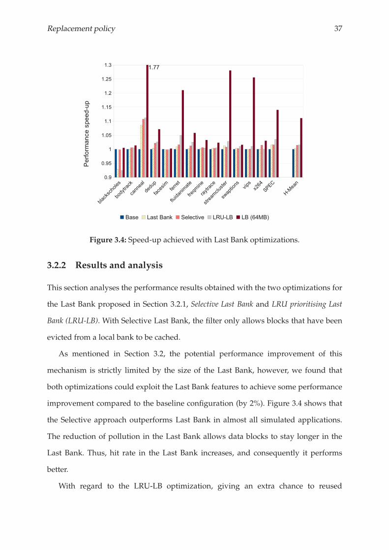
Figure 3.4: Speed-up achieved with Last Bank optimizations.
3.2.2 Results and analysis
This section analyses the performance results obtained with the two optimizations for
the Last Bank proposed in Section 3.2.1, Selective Last Bank and LRU prioritising Last
Bank (LRU-LB). With Selective Last Bank, the filter only allows blocks that have been
evicted from a local bank to be cached.
As mentioned in Section 3.2, the potential performance improvement of this
mechanism is strictly limited by the size of the Last Bank, however, we found that
both optimizations could exploit the Last Bank features to achieve some performance
improvement compared to the baseline configuration (by 2%). Figure 3.4 shows that
the Selective approach outperforms Last Bank in almost all simulated applications.
The reduction of pollution in the Last Bank allows data blocks to stay longer in the
Last Bank. Thus, hit rate in the Last Bank increases, and consequently it performs
better.
With regard to the LRU-LB optimization, giving an extra chance to reused
38 Chapter 3.
addresses before being evicted from the NUCA cache has two direct consequences:
1) if accessed, they are closer to cores, which means lower access latency, and 2) the
number of reused addresses stored in the NUCA cache is higher. This translates into
an overall performance improvement of 2%. Moreover, LRU-LB also outperforms the
regular Last Bank configuration with most of simulated applications.
3.2.3 Summary
In this section we have introduced Last Bank. This is a simple mechanism that acts
as victim cache for the regular NUCA banks. Moreover, we have also presented
two optimizations for the Last Bank that exploit the features of this mechanism,
and then, increases its performance benefits. However, our performance results show
that assuming a small Last Bank (64 KBytes), this mechanism achieves negligible
performance improvements, while a larger (but non-afforable) implementation of 64
MBytes outperforms the baseline configuration by 11%.
Although this mechanism work well with small caches [48], Last Bank requires
non-affordable hardware overheads to get significant benefits when a larger
configuration is assumed. These results discourage us from going on with the Last
Bank approach, so wemove on and propose other replacement techniques that require
similar hardware than the Last Bank, but obtain higher benefits in terms of both
performance and energy consumption.
3.3 LRU-PEA
When an incoming data block enters into the NUCA cache, the placement policy
determines in which NUCA bank it will be placed. Then, the replacement policy
determines (1) which data block must be evicted from the bank to leave space for the
new data (data eviction policy), and (2) which position within the replacement stack the
incoming data will occupy (e.g. MRU or LRU). This decision is known as data insertion
Replacement policy 39
policy. Replacement policies in traditional cache memories are composed by these two
sub-policies, however, D-NUCA incorporates one last decision to determine the final
destination of the evicted data block. We call it data target policy.
In this section we introduce the Least Recently Used with Priority Eviction Approach
(LRU-PEA) replacement policy. This policy focuses on optimizing the performance of
applications on a CMP-NUCA architecture by analyzing data behaviour within the
NUCA cache and trying to keep the most accessed data in cache as long as possible. In
order to describe how this policy works, we describe separately the two sub-policies
that the LRU-PEA modifies: data eviction policy and data target policy. With regard to
data insertion policy, the incoming data block will occupy the MRU position in the
replacement stack.
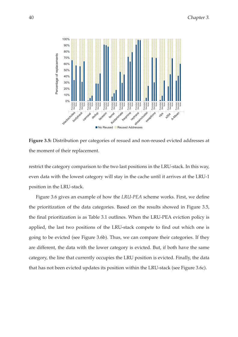
3.3.1 Data Eviction Policy
Being able to apply migration movements within the cache in one of the most
interesting features of NUCA cache memories. This enables recently accessed data
to be stored close to the requesting core in order to optimize access response times for
future accesses. We take advantage of this feature to classify data in the NUCA cache
relying on their last migration action: (1) promoted, (2) demoted, and (3) none. Figure 3.5
shows the percentage of resued and non-reused evicted addresses that belonged to
each of these three categories at the moment of their replacement. We observe that the
probabilities of a data block to return to the NUCA cache are higher if it belongs to the
promoted category than if it does to other category.
Based on this observation, LRU-PEA statically prioritises the previously defined
categories (promoted, demoted and none), and evicts from the NUCA cache the data
block that belongs to the lowest category. Having a static prioritization, however,
could cause the highest-category data to monopolize the NUCA cache, or even cause
a simple data block to stay in the cache forever. In order to avoid these situations, we
40 Chapter 3.
Figure 3.5: Distribution per categories of resued and non-reused evicted addresses at
the moment of their replacement.
restrict the category comparison to the two last positions in the LRU-stack. In this way,
even data with the lowest category will stay in the cache until it arrives at the LRU-1
position in the LRU-stack.
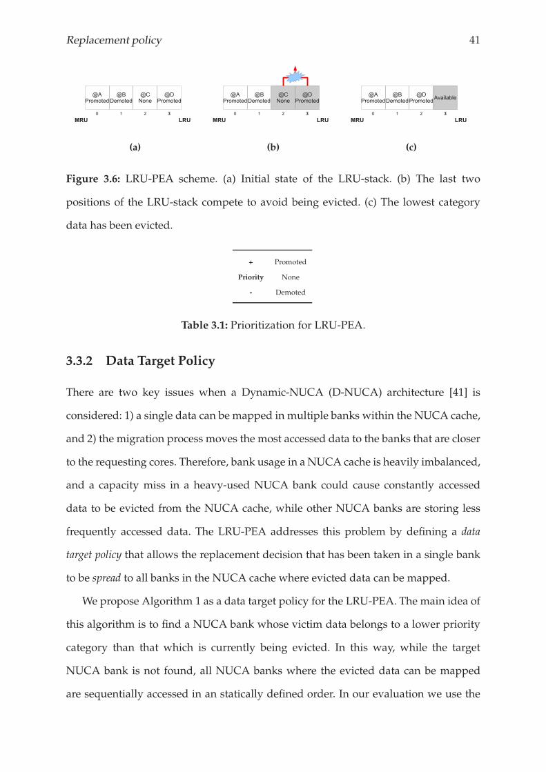
Figure 3.6 gives an example of how the LRU-PEA scheme works. First, we define
the prioritization of the data categories. Based on the results showed in Figure 3.5,
the final prioritization is as Table 3.1 outlines. When the LRU-PEA eviction policy is
applied, the last two positions of the LRU-stack compete to find out which one is
going to be evicted (see Figure 3.6b). Thus, we can compare their categories. If they
are different, the data with the lower category is evicted. But, if both have the same
category, the line that currently occupies the LRU position is evicted. Finally, the data
that has not been evicted updates its position within the LRU-stack (see Figure 3.6c).
Replacement policy 41
(a) (b) (c)
Figure 3.6: LRU-PEA scheme. (a) Initial state of the LRU-stack. (b) The last two
positions of the LRU-stack compete to avoid being evicted. (c) The lowest category
data has been evicted.
+ Promoted
Priority None
- Demoted
Table 3.1: Prioritization for LRU-PEA.
3.3.2 Data Target Policy
There are two key issues when a Dynamic-NUCA (D-NUCA) architecture [41] is
considered: 1) a single data can be mapped in multiple banks within the NUCA cache,
and 2) the migration process moves the most accessed data to the banks that are closer
to the requesting cores. Therefore, bank usage in a NUCA cache is heavily imbalanced,
and a capacity miss in a heavy-used NUCA bank could cause constantly accessed
data to be evicted from the NUCA cache, while other NUCA banks are storing less
frequently accessed data. The LRU-PEA addresses this problem by defining a data
target policy that allows the replacement decision that has been taken in a single bank
to be spread to all banks in the NUCA cache where evicted data can be mapped.
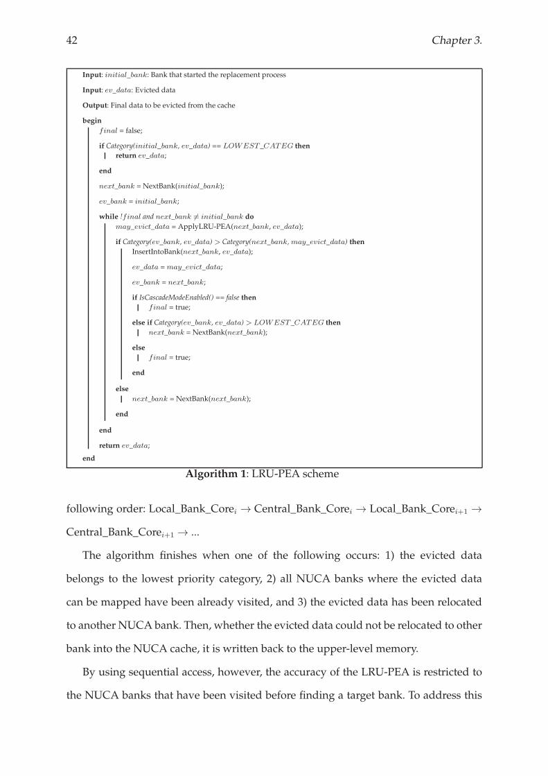
We propose Algorithm 1 as a data target policy for the LRU-PEA. The main idea of
this algorithm is to find a NUCA bank whose victim data belongs to a lower priority
category than that which is currently being evicted. In this way, while the target
NUCA bank is not found, all NUCA banks where the evicted data can be mapped
are sequentially accessed in an statically defined order. In our evaluation we use the
42 Chapter 3.
Input: initial_bank: Bank that started the replacement process
Input: ev_data: Evicted data
Output: Final data to be evicted from the cache
begin
final = false;
if Category(initial_bank, ev_data) == LOWEST_CATEG then
return ev_data;
end
next_bank = NextBank(initial_bank);
ev_bank = initial_bank;
while !final and next_bank 6= initial_bank do
may_evict_data = ApplyLRU-PEA(next_bank, ev_data);
if Category(ev_bank, ev_data) > Category(next_bank,may_evict_data) then
InsertIntoBank(next_bank, ev_data);
ev_data = may_evict_data;
ev_bank = next_bank;
if IsCascadeModeEnabled() == false then
final = true;
else if Category(ev_bank, ev_data) > LOWEST_CATEG then
next_bank = NextBank(next_bank);
else
final = true;
end
else
next_bank = NextBank(next_bank);
end
end
return ev_data;
end
Algorithm 1: LRU-PEA scheme
following order: Local_Bank_Corei → Central_Bank_Corei → Local_Bank_Corei+1 →
Central_Bank_Corei+1 → ...
The algorithm finishes when one of the following occurs: 1) the evicted data
belongs to the lowest priority category, 2) all NUCA banks where the evicted data
can be mapped have been already visited, and 3) the evicted data has been relocated
to another NUCA bank. Then, whether the evicted data could not be relocated to other
bank into the NUCA cache, it is written back to the upper-level memory.
By using sequential access, however, the accuracy of the LRU-PEA is restricted to
the NUCA banks that have been visited before finding a target bank. To address this
Replacement policy 43
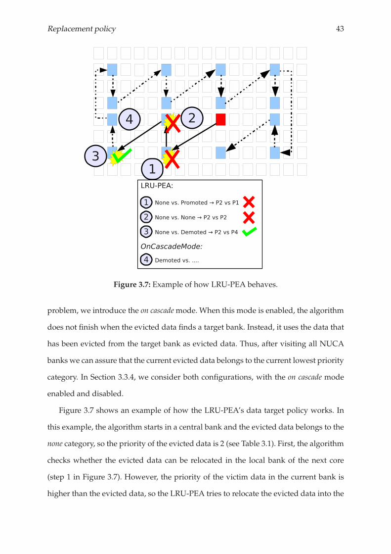
Figure 3.7: Example of how LRU-PEA behaves.
problem, we introduce the on cascademode. When this mode is enabled, the algorithm
does not finish when the evicted data finds a target bank. Instead, it uses the data that
has been evicted from the target bank as evicted data. Thus, after visiting all NUCA
banks we can assure that the current evicted data belongs to the current lowest priority
category. In Section 3.3.4, we consider both configurations, with the on cascade mode
enabled and disabled.
Figure 3.7 shows an example of how the LRU-PEA’s data target policy works. In
this example, the algorithm starts in a central bank and the evicted data belongs to the
none category, so the priority of the evicted data is 2 (see Table 3.1). First, the algorithm
checks whether the evicted data can be relocated in the local bank of the next core
(step 1 in Figure 3.7). However, the priority of the victim data in the current bank is
higher than the evicted data, so the LRU-PEA tries to relocate the evicted data into the
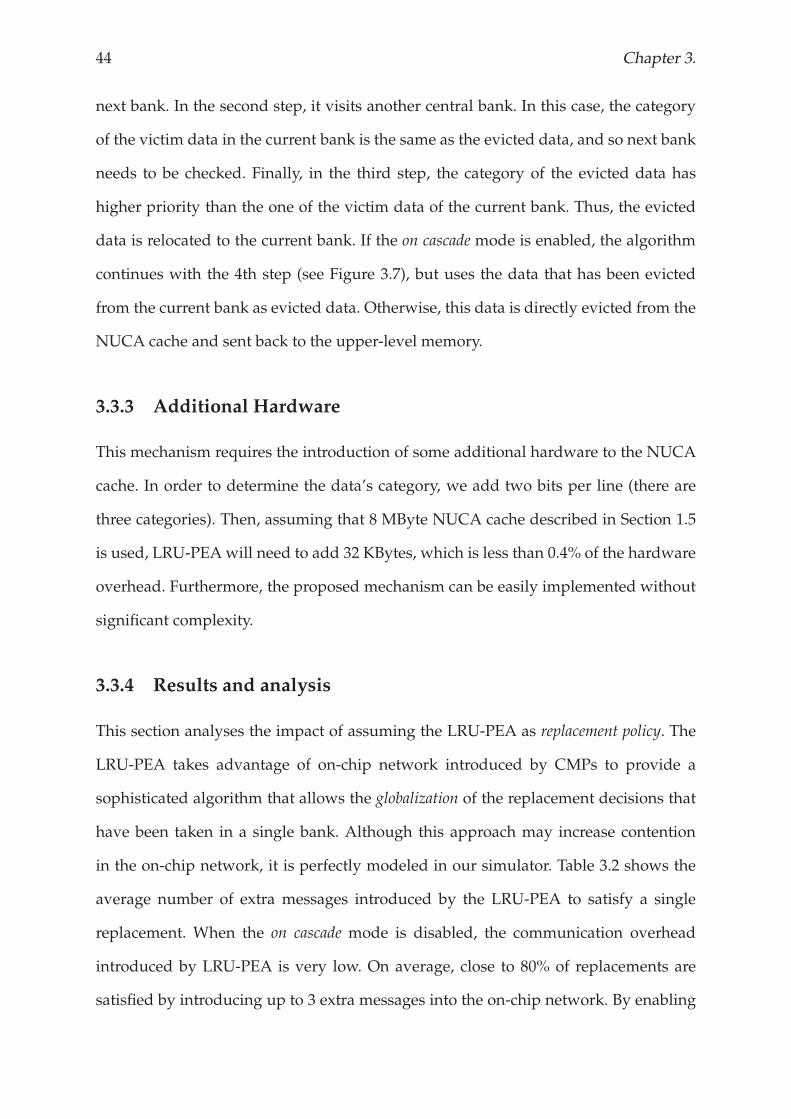
44 Chapter 3.
next bank. In the second step, it visits another central bank. In this case, the category
of the victim data in the current bank is the same as the evicted data, and so next bank
needs to be checked. Finally, in the third step, the category of the evicted data has
higher priority than the one of the victim data of the current bank. Thus, the evicted
data is relocated to the current bank. If the on cascade mode is enabled, the algorithm
continues with the 4th step (see Figure 3.7), but uses the data that has been evicted
from the current bank as evicted data. Otherwise, this data is directly evicted from the
NUCA cache and sent back to the upper-level memory.
3.3.3 Additional Hardware
This mechanism requires the introduction of some additional hardware to the NUCA
cache. In order to determine the data’s category, we add two bits per line (there are
three categories). Then, assuming that 8 MByte NUCA cache described in Section 1.5
is used, LRU-PEAwill need to add 32 KBytes, which is less than 0.4% of the hardware
overhead. Furthermore, the proposed mechanism can be easily implemented without
significant complexity.
3.3.4 Results and analysis
This section analyses the impact of assuming the LRU-PEA as replacement policy. The
LRU-PEA takes advantage of on-chip network introduced by CMPs to provide a
sophisticated algorithm that allows the globalization of the replacement decisions that
have been taken in a single bank. Although this approach may increase contention
in the on-chip network, it is perfectly modeled in our simulator. Table 3.2 shows the
average number of extra messages introduced by the LRU-PEA to satisfy a single
replacement. When the on cascade mode is disabled, the communication overhead
introduced by LRU-PEA is very low. On average, close to 80% of replacements are
satisfied by introducing up to 3 extra messages into the on-chip network. By enabling
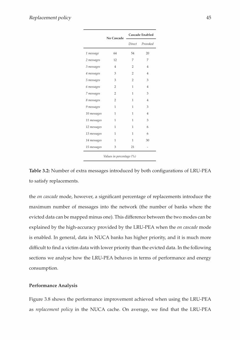
Replacement policy 45
No CascadeCascade Enabled
Direct Provoked
1 message 64 54 20
2 messages 12 7 7
3 messages 4 2 4
4 messages 3 2 4
5 messages 3 2 3
6 messages 2 1 4
7 messages 2 1 3
8 messages 2 1 4
9 messages 1 1 3
10 messages 1 1 4
11 messages 1 1 3
12 messages 1 1 6
13 messages 1 1 6
14 messages 1 1 30
15 messages 3 21 -
Values in percentage (%)
Table 3.2: Number of extra messages introduced by both configurations of LRU-PEA
to satisfy replacements.
the on cascade mode, however, a significant percentage of replacements introduce the
maximum number of messages into the network (the number of banks where the
evicted data can bemappedminus one). This difference between the twomodes can be
explained by the high-accuracy provided by the LRU-PEA when the on cascade mode
is enabled. In general, data in NUCA banks has higher priority, and it is much more
difficult to find a victim data with lower priority than the evicted data. In the following
sections we analyse how the LRU-PEA behaves in terms of performance and energy
consumption.
Performance Analysis
Figure 3.8 shows the performance improvement achieved when using the LRU-PEA
as replacement policy in the NUCA cache. On average, we find that the LRU-PEA
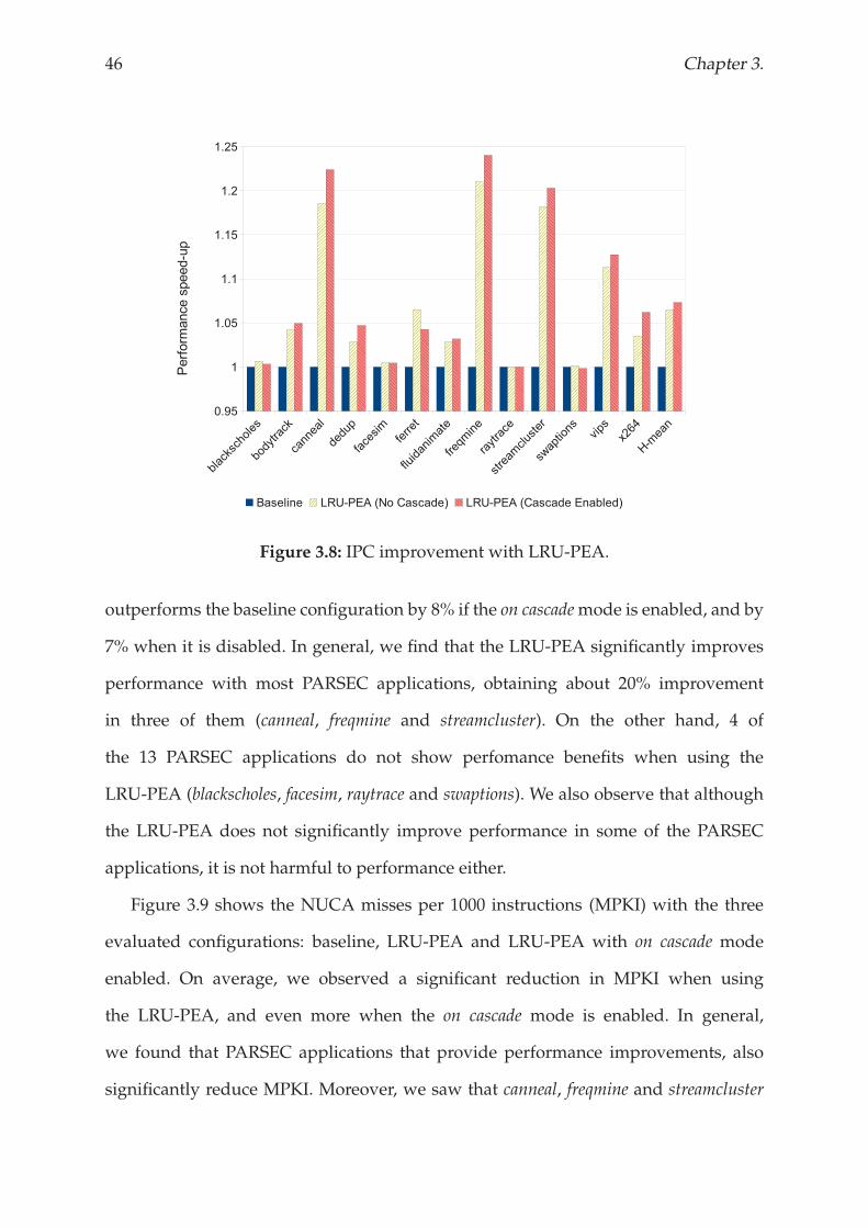
46 Chapter 3.
Figure 3.8: IPC improvement with LRU-PEA.
outperforms the baseline configuration by 8% if the on cascademode is enabled, and by
7% when it is disabled. In general, we find that the LRU-PEA significantly improves
performance with most PARSEC applications, obtaining about 20% improvement
in three of them (canneal, freqmine and streamcluster). On the other hand, 4 of
the 13 PARSEC applications do not show perfomance benefits when using the
LRU-PEA (blackscholes, facesim, raytrace and swaptions). We also observe that although
the LRU-PEA does not significantly improve performance in some of the PARSEC
applications, it is not harmful to performance either.
Figure 3.9 shows the NUCA misses per 1000 instructions (MPKI) with the three
evaluated configurations: baseline, LRU-PEA and LRU-PEA with on cascade mode
enabled. On average, we observed a significant reduction in MPKI when using
the LRU-PEA, and even more when the on cascade mode is enabled. In general,
we found that PARSEC applications that provide performance improvements, also
significantly reduce MPKI. Moreover, we saw that canneal, freqmine and streamcluster
Replacement policy 47
Figure 3.9: Misses per thousand instructions with LRU-PEA.
(the applications that provide the highest performance improvement with LRU-PEA)
also have the highest MPKI. In contrast, applications with an MPKI close to zero do
not usually improve performance when the LRU-PEA is used.
Regarding those applications where the LRU-PEA does not improve performance,
blackscholes and swaptions are financial applications with small working sets, so their
cache requirements are restricted. On the other hand, raytrace and facesim have very
big working sets, but they are computationally intensive and mainly exploit temporal
locality.
Energy Consumption Analysis
The energy consumption is analysed by using the Energy per Instruction (EPI) metric.
Figure 3.10 shows that, on average, the LRU-PEA reduces the energy consumed per
each instruction compared to the baseline architecture by 5% for both configurations
(with and without the on cascade mode enabled). In particular, the LRU-PEA
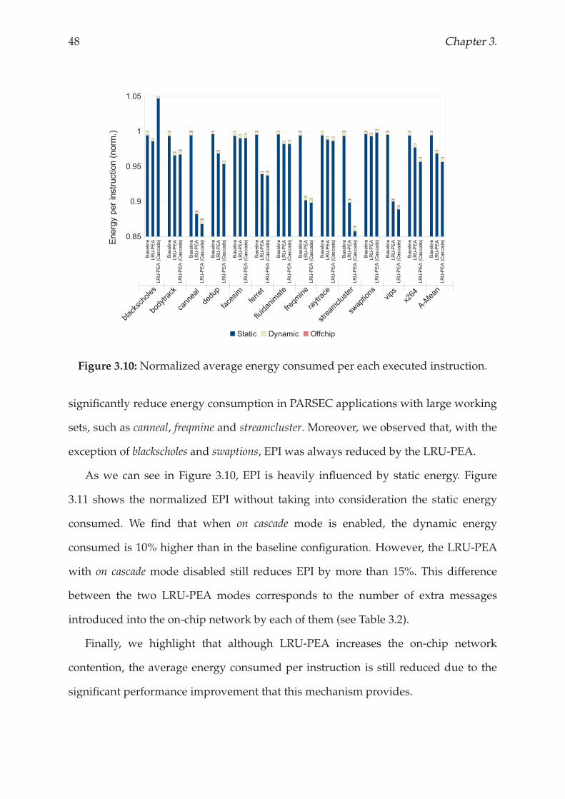
48 Chapter 3.
Figure 3.10:Normalized average energy consumed per each executed instruction.
significantly reduce energy consumption in PARSEC applications with large working
sets, such as canneal, freqmine and streamcluster. Moreover, we observed that, with the
exception of blackscholes and swaptions, EPI was always reduced by the LRU-PEA.
As we can see in Figure 3.10, EPI is heavily influenced by static energy. Figure
3.11 shows the normalized EPI without taking into consideration the static energy
consumed. We find that when on cascade mode is enabled, the dynamic energy
consumed is 10% higher than in the baseline configuration. However, the LRU-PEA
with on cascade mode disabled still reduces EPI by more than 15%. This difference
between the two LRU-PEA modes corresponds to the number of extra messages
introduced into the on-chip network by each of them (see Table 3.2).
Finally, we highlight that although LRU-PEA increases the on-chip network
contention, the average energy consumed per instruction is still reduced due to the
significant performance improvement that this mechanism provides.
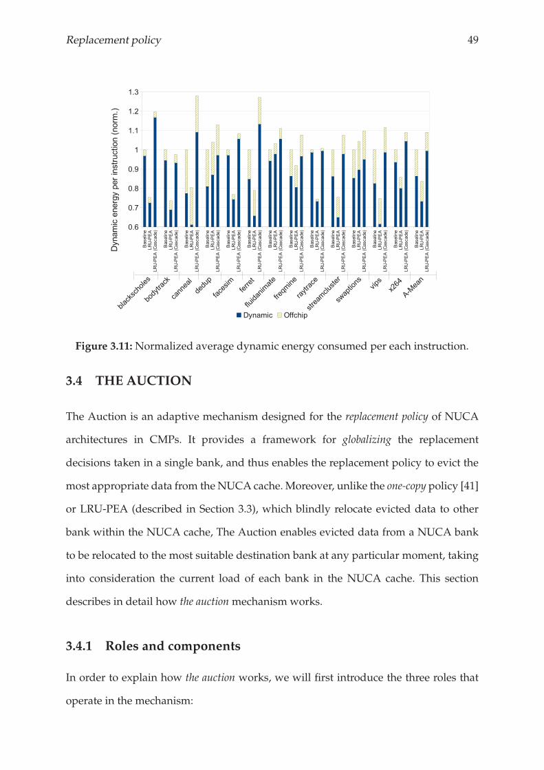
Replacement policy 49
Figure 3.11:Normalized average dynamic energy consumed per each instruction.
3.4 THE AUCTION
The Auction is an adaptive mechanism designed for the replacement policy of NUCA
architectures in CMPs. It provides a framework for globalizing the replacement
decisions taken in a single bank, and thus enables the replacement policy to evict the
most appropriate data from the NUCA cache. Moreover, unlike the one-copy policy [41]
or LRU-PEA (described in Section 3.3), which blindly relocate evicted data to other
bank within the NUCA cache, The Auction enables evicted data from a NUCA bank
to be relocated to the most suitable destination bank at any particular moment, taking
into consideration the current load of each bank in the NUCA cache. This section
describes in detail how the auction mechanism works.
3.4.1 Roles and components
In order to explain how the auction works, we will first introduce the three roles that
operate in the mechanism:
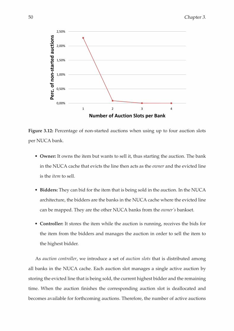
50 Chapter 3.
1,50%
2,00%
2,50%
startedauctions
0,00%
0,50%
1,00%
1 2 3 4
Perc.ofnons
Number of Auction Slots per Bank
Figure 3.12: Percentage of non-started auctions when using up to four auction slots
per NUCA bank.
• Owner: It owns the item but wants to sell it, thus starting the auction. The bank
in the NUCA cache that evicts the line then acts as the owner and the evicted line
is the item to sell.
• Bidders: They can bid for the item that is being sold in the auction. In the NUCA
architecture, the bidders are the banks in the NUCA cache where the evicted line
can be mapped. They are the other NUCA banks from the owner’s bankset.
• Controller: It stores the item while the auction is running, receives the bids for
the item from the bidders and manages the auction in order to sell the item to
the highest bidder.
As auction controller, we introduce a set of auction slots that is distributed among
all banks in the NUCA cache. Each auction slot manages a single active auction by
storing the evicted line that is being sold, the current highest bidder and the remaining
time. When the auction finishes the corresponding auction slot is deallocated and
becomes available for forthcoming auctions. Therefore, the number of active auctions
Replacement policy 51
per NUCA bank is limited by the number of auction slots that it has. Figure 3.12
shows the percentage of auctions that cannot be started because there are no auction
slots available when using up to four auction slots per NUCA bank. We observe that
assuming one auction slot per bank, just 2.3% of evicted lines can not be relocated.
Moreover, we find that using more auction slots per NUCA bank, the percentage
of non-started auctions dramatically decreases. At this point, the challenge is to
determine the optimal number of auction slots that provides high accuracy without
introducing prohibitive hardware overhead. In the remainder of the chapter, we
assume having two auction slots per NUCA bank. This configuration provides a good
trade-off between auction accuracy and hardware requirements.
3.4.2 How The Auction works
Figure 3.13 shows the three steps of the auction. It starts when there is a replacement
in a bank in the NUCA cache and it has at least one auction slot available – otherwise
the auction can not be started and the evicted line is directly sent to the main memory
–. The bank that is replacing data (the owner) moves the evicted line (the item) to the
controller (the corresponding auction slot) and sets the auction deadline (Figure 3.13a).
At the same time, the owner invites the other banks from the bankset (the bidders) to join
the auction and bid for the item. Recall that an addressmaps to a bankset and can reside
within any bank of the bankset. Thus, in our baseline architecture the evicted line can
only be mapped to 16 banks within the whole NUCA cache. When a bidder finds out
that a data block has been evicted from the NUCA cache, it decides whether to bid
for it (Figure 3.13b). If the bidder is interested in getting the evicted data, it notifies the
controller who manages the auction. Otherwise, the bidder ignores the current auction.
Finally, when the auction time expires (Figure 3.13c), the controller determines the
final destination of the evicted data based on the received bids and the implemented
heuristic, and sends it to the winning bidder. Moreover, in order to avoid recursively
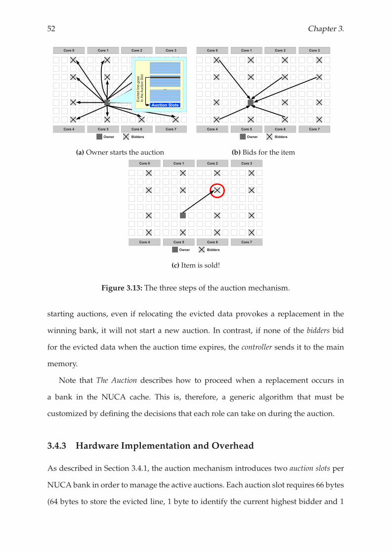
52 Chapter 3.
(a) Owner starts the auction (b) Bids for the item
(c) Item is sold!
Figure 3.13: The three steps of the auction mechanism.
starting auctions, even if relocating the evicted data provokes a replacement in the
winning bank, it will not start a new auction. In contrast, if none of the bidders bid
for the evicted data when the auction time expires, the controller sends it to the main
memory.
Note that The Auction describes how to proceed when a replacement occurs in
a bank in the NUCA cache. This is, therefore, a generic algorithm that must be
customized by defining the decisions that each role can take on during the auction.
3.4.3 Hardware Implementation and Overhead
As described in Section 3.4.1, the auction mechanism introduces two auction slots per
NUCA bank in order to manage the active auctions. Each auction slot requires 66 bytes
(64 bytes to store the evicted line, 1 byte to identify the current highest bidder and 1
Replacement policy 53
byte to determine the remaining time), the hardware overhead of this configuration is
33 KBytes (which is less than 0.4% of the total hardware used by the NUCA cache).
Apart from hardware overheads, the auction also introduces extra messages into the
on-chip network (i.e. messages to join the auction and bids). The impact of introducing
these messages into the network is thoroughly analysed in Section 3.4.5.
3.4.4 Implementing an Auction Approach
The Auction algorithm defines how the owner and the controller behave while an
auction is running, however, it does not define whether a bidder should bid for
the evicted data block or not. The generality of this scheme opens a wide area to
explore in the replacement policy for NUCA caches in which architects may use The
Auction framework to implement smart auction-like replacement policies. This section
describes two examples of auction approaches – bank usage imbalance (AUC-IMB) and
prioritising most accessed data (AUC-ACC) – that enable to determine the quality of data
during the auction, and thus enable bidders to compare the evicted data that is being
sold with their own data.
Providing a significant number of bids per auction to the controller is crucial to
have high auction accuracy (i.e. the goodness of its final decision). Thus, increasing
the number of bits per auction, an auction-like replacement policy will 1) provide
controller more options to determine the most appropriate destination bank for the
evicted data within the NUCA cache, and 2) reduce the number of auctions that finish
without receiving any bid.
Bank Usage Imbalance (AUC-IMB)
There are two key issues when a Dynamic-NUCA (D-NUCA) architecture [41] is
considered: 1) a single data can be mapped in multiple banks within the NUCA cache,
and 2) the migration process moves the most accessed data to the banks that are closer
54 Chapter 3.
to the requesting cores. Therefore, bank usage in a NUCA cache is heavily imbalanced,
and a capacity miss in a heavy-used NUCA bank could cause constantly accessed
data to be evicted from the NUCA cache, while other NUCA banks are storing less
frequently accessed data.
We propose an auction approach that measures the usage rate of each bank. Thus,
least accessed banks could bid for evicted data from banks that are being constantly
accessed. We use the number of capacity replacements in each cache-set of NUCA banks
as our bank usage metric.
This auction approach works as follows: when a replacement occurs in a NUCA
bank, the owner notifies the bidders that the auction has started, and sends them
the current replacement counter. Then, when a bidder receives the message from the
owner, it checks whether its current replacement counter is lower than the counter
attached to the message. If it is lower, the current bank bids for the evicted data by
sending to the controller the bank identifier and its replacement counter. At the same
time, the controller that manages the auction is storing the current winner and its
replacement counter. When a bid arrives to the controller, it checks if the replacement
counter from the bid is lower than the one from the current winner. If so, the incoming
bid becomes the current winner, otherwise the bid is discarded. Finally, when the
auction time expires, controller sends the evicted data to the bidder with the lowest
replacement counter.
Migration movements make most frequently accessed data to be stored in local
banks, thus if the controller receives bids from both types of banks, local and central,
it will always prefer to send the item to the central bank. Then, the controller works
as follows: If the first bid that arrives to the controller comes from a central bank,
the auction finishes and the item is directly sent to the bidder. If the first bidder is a
local bank, however, the controller sets the auction deadline to 20 cycles and waits for
other bids from central banks. We have experimentally observed that even with high
network contention most bids arrive to the controller in 20 cycles from the arrival of
Replacement policy 55
the first bid.
Unfortunately, this approach is not affordable without restricting the number of
bits used by each replacement counter. Therefore, in order to implement this approach,
in addition to restricting the bits dedicated to the replacement counter, we have to
implement a reset system that initializes the replacement counters of other NUCA
banks when one of them arrives at the maximum value. If this is not done, when a
replacement counter overflows, it could not be compared with other counters. Thus,
when a replacement counter arrives at its maximum value, the owner sends the
bidders the reset signal with the message that notifies that an auction has started.
We evaluate this approach by assuming there is an 8-bit replacement counter
per cache-set in all NUCA banks. We have chosen this size on the basis of the
following issues: additional hardware introduced (bits for the replacement counter
and comparators), accuracy obtained, and reset frequency.
Hardware implementation and overheads: This approach requires the
introduction of 8 bits in every cache set and auction slot. Thus, assuming the
baseline architecture described in Section 2.1, this means adding 16.5 KBytes to
the hardware overhead required by The Auction (33 KBytes). Then, this approach
requires introducing 49.5 Kbytes to the 8 MByte NUCA cache, which signifies less
than 0.6% of the hardware overhead. Moreover, it increases the size of both auction
messages, auction invitations and bids, because these messages need to include the
8-bit replacement counter. The auction invitation message sent by the owner also
requires one bit more for the reset signal. We take these overheads into account when
evaluating this approach.
Prioritising most accessed data (AUC-ACC)
This auction approach focuses on keeping the most accessed data in the NUCA cache.
When the bidder receives the auction start notification, it checks whether the evicted
data has been accessed more times than the data that is currently occupying the last
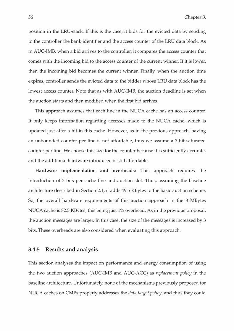
56 Chapter 3.
position in the LRU-stack. If this is the case, it bids for the evicted data by sending
to the controller the bank identifier and the access counter of the LRU data block. As
in AUC-IMB, when a bid arrives to the controller, it compares the access counter that
comes with the incoming bid to the access counter of the current winner. If it is lower,
then the incoming bid becomes the current winner. Finally, when the auction time
expires, controller sends the evicted data to the bidder whose LRU data block has the
lowest access counter. Note that as with AUC-IMB, the auction deadline is set when
the auction starts and then modified when the first bid arrives.
This approach assumes that each line in the NUCA cache has an access counter.
It only keeps information regarding accesses made to the NUCA cache, which is
updated just after a hit in this cache. However, as in the previous approach, having
an unbounded counter per line is not affordable, thus we assume a 3-bit saturated
counter per line. We choose this size for the counter because it is sufficiently accurate,
and the additional hardware introduced is still affordable.
Hardware implementation and overheads: This approach requires the
introduction of 3 bits per cache line and auction slot. Thus, assuming the baseline
architecture described in Section 2.1, it adds 49.5 KBytes to the basic auction scheme.
So, the overall hardware requirements of this auction approach in the 8 MBytes
NUCA cache is 82.5 KBytes, this being just 1% overhead. As in the previous proposal,
the auction messages are larger. In this case, the size of the messages is increased by 3
bits. These overheads are also considered when evaluating this approach.
3.4.5 Results and analysis
This section analyses the impact on performance and energy consumption of using
the two auction approaches (AUC-IMB and AUC-ACC) as replacement policy in the
baseline architecture. Unfortunately, none of the mechanisms previously proposed for
NUCA caches on CMPs properly addresses the data target policy, and thus they could
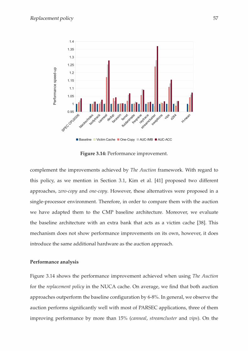
Replacement policy 57
Figure 3.14: Performance improvement.
complement the improvements achieved by The Auction framework. With regard to
this policy, as we mention in Section 3.1, Kim et al. [41] proposed two different
approaches, zero-copy and one-copy. However, these alternatives were proposed in a
single-processor environment. Therefore, in order to compare them with the auction
we have adapted them to the CMP baseline architecture. Moreover, we evaluate
the baseline architecture with an extra bank that acts as a victim cache [38]. This
mechanism does not show performance improvements on its own, however, it does
introduce the same additional hardware as the auction approach.
Performance analysis
Figure 3.14 shows the performance improvement achieved when using The Auction
for the replacement policy in the NUCA cache. On average, we find that both auction
approaches outperform the baseline configuration by 6-8%. In general, we observe the
auction performs significantly well with most of PARSEC applications, three of them
improving performance by more than 15% (canneal, streamcluster and vips). On the
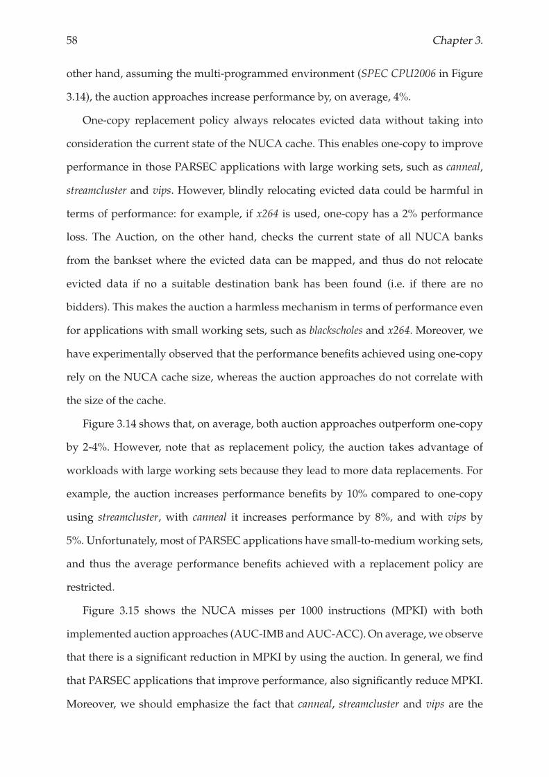
58 Chapter 3.
other hand, assuming the multi-programmed environment (SPEC CPU2006 in Figure
3.14), the auction approaches increase performance by, on average, 4%.
One-copy replacement policy always relocates evicted data without taking into
consideration the current state of the NUCA cache. This enables one-copy to improve
performance in those PARSEC applications with large working sets, such as canneal,
streamcluster and vips. However, blindly relocating evicted data could be harmful in
terms of performance: for example, if x264 is used, one-copy has a 2% performance
loss. The Auction, on the other hand, checks the current state of all NUCA banks
from the bankset where the evicted data can be mapped, and thus do not relocate
evicted data if no a suitable destination bank has been found (i.e. if there are no
bidders). This makes the auction a harmless mechanism in terms of performance even
for applications with small working sets, such as blackscholes and x264. Moreover, we
have experimentally observed that the performance benefits achieved using one-copy
rely on the NUCA cache size, whereas the auction approaches do not correlate with
the size of the cache.
Figure 3.14 shows that, on average, both auction approaches outperform one-copy
by 2-4%. However, note that as replacement policy, the auction takes advantage of
workloads with large working sets because they lead to more data replacements. For
example, the auction increases performance benefits by 10% compared to one-copy
using streamcluster, with canneal it increases performance by 8%, and with vips by
5%. Unfortunately, most of PARSEC applications have small-to-medium working sets,
and thus the average performance benefits achieved with a replacement policy are
restricted.
Figure 3.15 shows the NUCA misses per 1000 instructions (MPKI) with both
implemented auction approaches (AUC-IMB andAUC-ACC).On average, we observe
that there is a significant reduction in MPKI by using the auction. In general, we find
that PARSEC applications that improve performance, also significantly reduce MPKI.
Moreover, we should emphasize the fact that canneal, streamcluster and vips are the
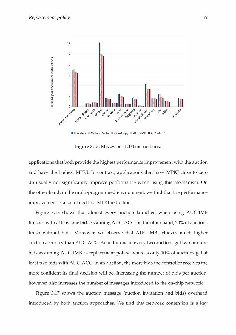
Replacement policy 59
Figure 3.15:Misses per 1000 instructions.
applications that both provide the highest performance improvement with the auction
and have the highest MPKI. In contrast, applications that have MPKI close to zero
do usually not significantly improve performance when using this mechanism. On
the other hand, in the multi-programmed environment, we find that the performance
improvement is also related to a MPKI reduction.
Figure 3.16 shows that almost every auction launched when using AUC-IMB
finishes with at least one bid. AssumingAUC-ACC, on the other hand, 20% of auctions
finish without bids. Moreover, we observe that AUC-IMB achieves much higher
auction accuracy than AUC-ACC. Actually, one in every two auctions get two or more
bids assuming AUC-IMB as replacement policy, whereas only 10% of auctions get at
least two bids with AUC-ACC. In an auction, the more bids the controller receives the
more confident its final decision will be. Increasing the number of bids per auction,
however, also increases the number of messages introduced to the on-chip network.
Figure 3.17 shows the auction message (auction invitation and bids) overhead
introduced by both auction approaches. We find that network contention is a key
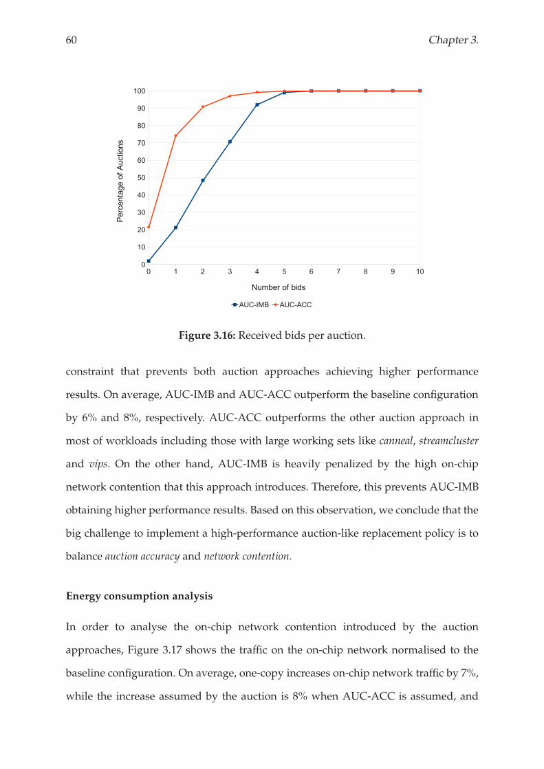
60 Chapter 3.
Figure 3.16: Received bids per auction.
constraint that prevents both auction approaches achieving higher performance
results. On average, AUC-IMB and AUC-ACC outperform the baseline configuration
by 6% and 8%, respectively. AUC-ACC outperforms the other auction approach in
most of workloads including those with large working sets like canneal, streamcluster
and vips. On the other hand, AUC-IMB is heavily penalized by the high on-chip
network contention that this approach introduces. Therefore, this prevents AUC-IMB
obtaining higher performance results. Based on this observation, we conclude that the
big challenge to implement a high-performance auction-like replacement policy is to
balance auction accuracy and network contention.
Energy consumption analysis
In order to analyse the on-chip network contention introduced by the auction
approaches, Figure 3.17 shows the traffic on the on-chip network normalised to the
baseline configuration. On average, one-copy increases on-chip network traffic by 7%,
while the increase assumed by the auction is 8% when AUC-ACC is assumed, and
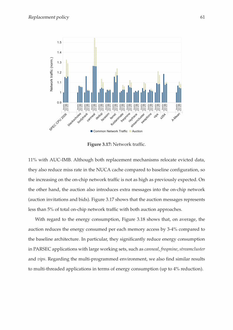
Replacement policy 61
Figure 3.17:Network traffic.
11% with AUC-IMB. Although both replacement mechanisms relocate evicted data,
they also reduce miss rate in the NUCA cache compared to baseline configuration, so
the increasing on the on-chip network traffic is not as high as previously expected. On
the other hand, the auction also introduces extra messages into the on-chip network
(auction invitations and bids). Figure 3.17 shows that the auction messages represents
less than 5% of total on-chip network traffic with both auction approaches.
With regard to the energy consumption, Figure 3.18 shows that, on average, the
auction reduces the energy consumed per each memory access by 3-4% compared to
the baseline architecture. In particular, they significantly reduce energy consumption
in PARSEC applications with large working sets, such as canneal, freqmine, streamcluster
and vips. Regarding the multi-programmed environment, we also find similar results
to multi-threaded applications in terms of energy consumption (up to 4% reduction).
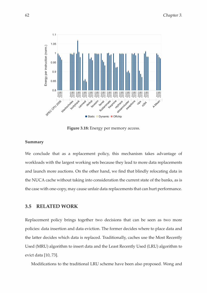
62 Chapter 3.
Figure 3.18: Energy per memory access.
Summary
We conclude that as a replacement policy, this mechanism takes advantage of
workloads with the largest working sets because they lead to more data replacements
and launch more auctions. On the other hand, we find that blindly relocating data in
the NUCA cache without taking into consideration the current state of the banks, as is
the casewith one-copy, may cause unfair data replacements that can hurt performance.
3.5 RELATED WORK
Replacement policy brings together two decisions that can be seen as two more
policies: data insertion and data eviction. The former decides where to place data and
the latter decides which data is replaced. Traditionally, caches use the Most Recently
Used (MRU) algorithm to insert data and the Least Recently Used (LRU) algorithm to
evict data [10, 73].
Modifications to the traditional LRU scheme have been also proposed. Wong and

Replacement policy 63
Bauer [84] modified the standard LRU to maintain data that exhibited higher temporal
locality. Alghazo et al. [5] proposed a mechanism called SF-LRU (Second-Chance
Frequency LRU). This scheme combines both the recentness (LRU) and frequency
(LFU) of blocks to decide which blocks to replace. Dybdahl et al. [27] also proposed
another LRU approach based on frequency of access in shared multiprocessor caches.
Kharbutli and Solihin [40] proposed a counter-based L2 cache replacement. This
approach includes an event counter with each line that is incremented under certain
circumstances. The line can then be evicted when this counter achieves a certain
threshold.
Recently, several papers have revisited data insertion policy. Qureshi et al. [71]
propose Line Distillation, a mechanism that tries to keep frequently accessed data in
a cache line and to evict unused data. This technique is based on the observation that,
generally, data is unlikely to be used in the lowest priority part of the LRU stack.
They also proposed LIP (LRU Insertion Policy), which places data in the LRU position
instead of the MRU position [68].
Dynamic NUCA cache memories incorporate one extra policy, that is data target
policy. This determines the final destination of the evicted data block. Several works
have recently proposed in the literature to efficiently manage NUCA caches [9, 36,
39, 41, 63]. However, none of them properly addresses replacement policy in NUCA
caches for CMPs.
3.6 CONCLUSIONS
The decentralized nature of NUCA prevents replacement policies previously
proposed in the literature from being effective in this kind of caches. As banks operate
independently from each other, their replacement decisions are restricted to a single
NUCA bank. Unfortunately, replacement policy in NUCA-based CMP architectures
has not been properly addressed before. Most of previous works have ignored the
64 Chapter 3.
replacement issue or adopted a replacement scheme that was originally designed for
being used with uniprocessors/uniform-cache memories. This chapter describes three
different approaches for dealingwith replacements in D-NUCA achitectures on CMPs.
We first propose Last Bank. This introduces an extra bank into the NUCA
cache memory that catches evicted data blocks from the other banks. Although this
mechanism work well with small caches [48], Last Bank requires non-affordable
hardware overheads to get significant benefits when a larger configuration is assumed.
Then, we propose LRU-PEA. This is an alternative to the traditional LRU replacement
policy. It aims to make more intelligent replacement decisions by protecting these
cache lines that are more likely to be reused in the near future. We observe that, on
average, the baseline configuration increases its performance benefits by 8% when
using LRU-PEA as replacement policy. Finally, we propose The Auction. This is a
framework that allows architects for implementing auction-like replacement policies
in future D-NUCA cache architectures. The Auction spreads replacement decisions
that have been taken in a single bank to the whole NUCA cache. Therefore, this enables
the replacement policy to select the most appropriate victim data block from the whole
NUCA cache. The implemented auction approaches increase performance benefits by
6-8% and reduce energy consumed by 4% compared to the baseline configuration.
Chapter 4
Access policy
Dynamic features provided by D-NUCA, like placement of data and migration movements,
make access policy a key constraint in NUCA caches. This chapter presents HK-NUCA, which
is an efficient and cost-effective search mechanism to reduce miss latency in the NUCA cache
and the on-chip network contention.

Access policy 67
4.1 INTRODUCTION
Dynamic features provided by D-NUCA, like multiple placement of data and
migration movements, make data search scheme a key constraint in this kind of
architectures. Prior works proposed different techniques to efficiently search data
in the NUCA banks which include access parallelization, prioritisation of most
frequently accessed banks, or prediction of the next bank to access, among others
[3, 41, 72]. In case of miss in the NUCA cache, however, these techniques must access
all banks from the corresponding bankset to ensure that the requested data block is
not in the NUCA cache before forwarding the request to the upper-level memory.
To address this situation, in this thesis we propose HK-NUCA, which is short
for (Home Knows where to find data within the NUCA cache). It uses home knowledge
to ascertain which banks could potentially have the requested data, thus it resolves
memory requests by accessing only to the subset of banks indicated by home. This
makes HK-NUCA significantly reduce on-chip network contention as well as miss
resolution time compared to other techniques previously proposed in the literature.
This translates into a reduction of the dynamic energy consumed by the memory
system of 40%, and an overall performance improvement of 6%.
The remainder of this chapter is structured as follows. Section 4.2 lays out the
motivation for this work by analysing the importance of data search algorithm in
D-NUCA. In Section 4.3, the proposed data search mechanism is described in detail,
followed by the analysis of the results that is presented in Section 4.4. Related work is
discussed in Section 4.5, and concluding remarks are given in Section 4.6.
4.2 MOTIVATION
NUCA designs have been classified on the basis of their placement policy as static
(S-NUCA) or dynamic (D-NUCA) [9, 41]. In an S-NUCA organization, the mapping
of data into banks is predetermined based on the block index, and thus can reside in
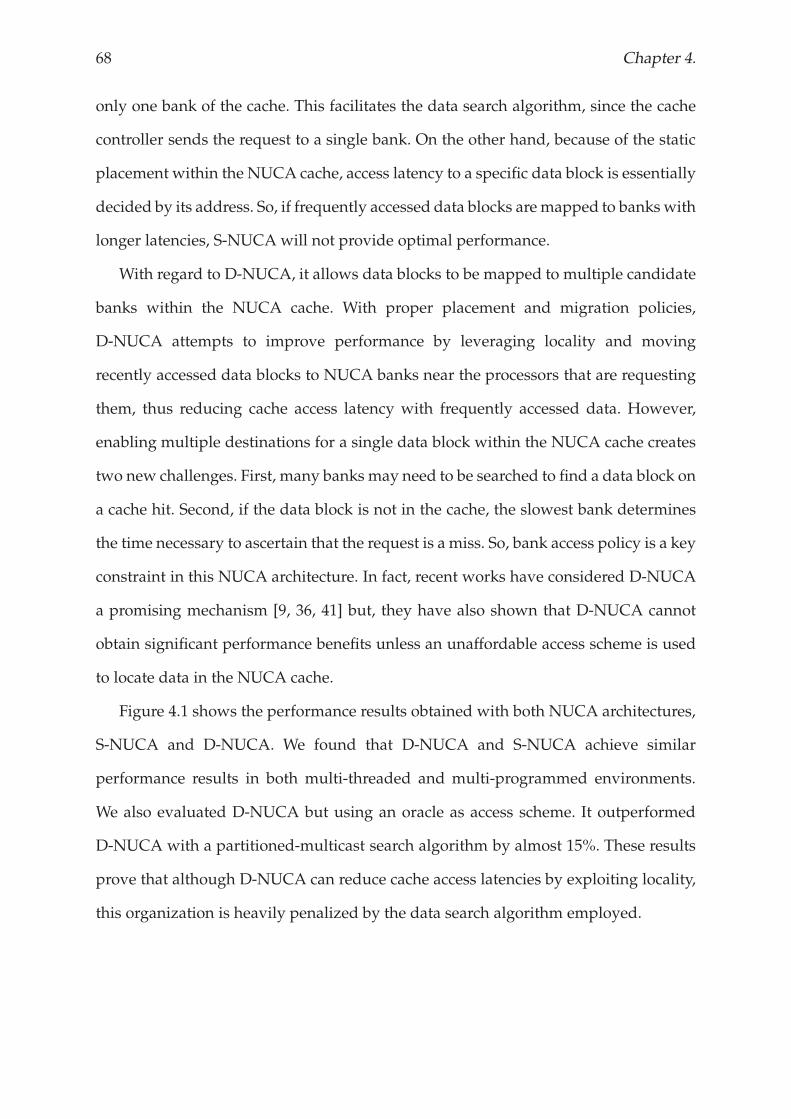
68 Chapter 4.
only one bank of the cache. This facilitates the data search algorithm, since the cache
controller sends the request to a single bank. On the other hand, because of the static
placement within the NUCA cache, access latency to a specific data block is essentially
decided by its address. So, if frequently accessed data blocks are mapped to banks with
longer latencies, S-NUCA will not provide optimal performance.
With regard to D-NUCA, it allows data blocks to be mapped to multiple candidate
banks within the NUCA cache. With proper placement and migration policies,
D-NUCA attempts to improve performance by leveraging locality and moving
recently accessed data blocks to NUCA banks near the processors that are requesting
them, thus reducing cache access latency with frequently accessed data. However,
enabling multiple destinations for a single data block within the NUCA cache creates
two new challenges. First, many banks may need to be searched to find a data block on
a cache hit. Second, if the data block is not in the cache, the slowest bank determines
the time necessary to ascertain that the request is a miss. So, bank access policy is a key
constraint in this NUCA architecture. In fact, recent works have considered D-NUCA
a promising mechanism [9, 36, 41] but, they have also shown that D-NUCA cannot
obtain significant performance benefits unless an unaffordable access scheme is used
to locate data in the NUCA cache.
Figure 4.1 shows the performance results obtained with both NUCA architectures,
S-NUCA and D-NUCA. We found that D-NUCA and S-NUCA achieve similar
performance results in both multi-threaded and multi-programmed environments.
We also evaluated D-NUCA but using an oracle as access scheme. It outperformed
D-NUCA with a partitioned-multicast search algorithm by almost 15%. These results
prove that although D-NUCA can reduce cache access latencies by exploiting locality,
this organization is heavily penalized by the data search algorithm employed.
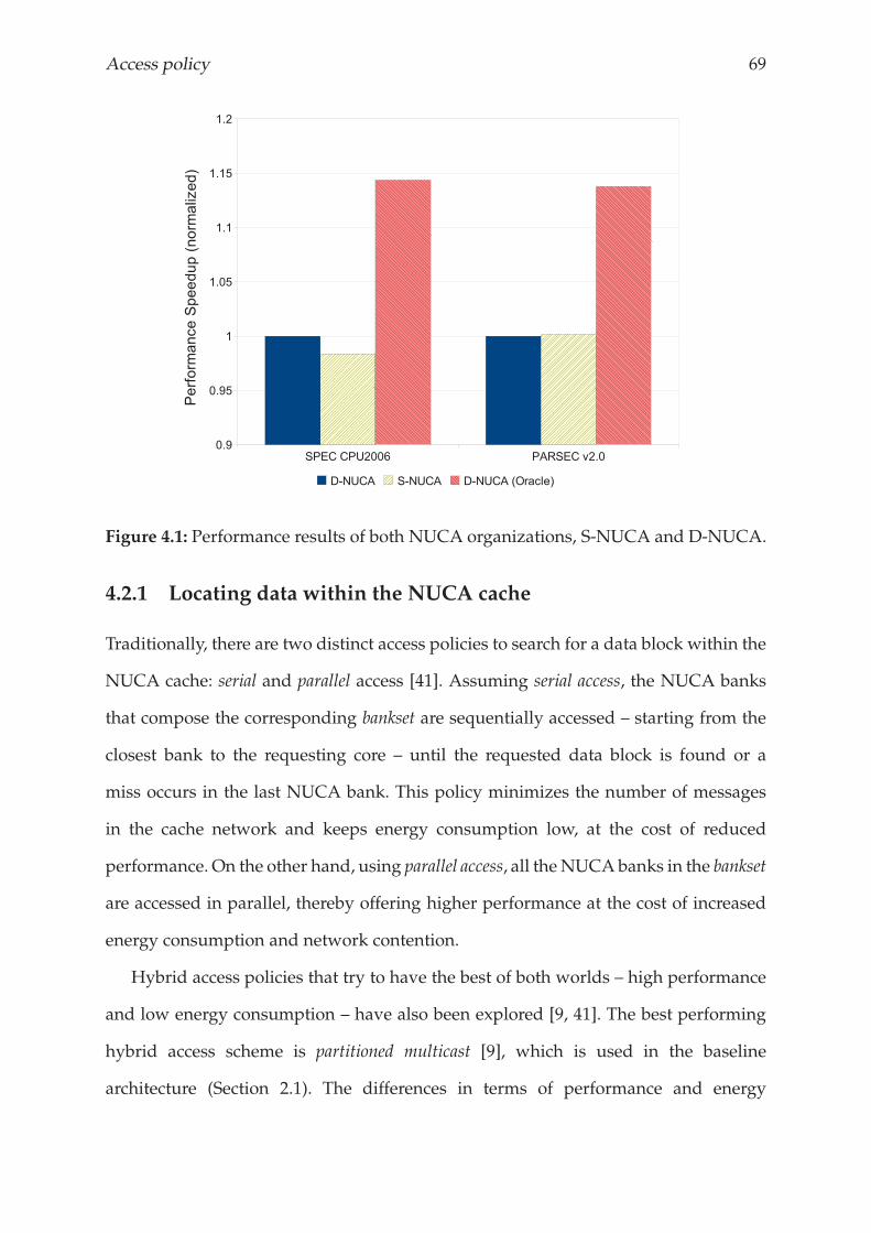
Access policy 69
Figure 4.1: Performance results of both NUCA organizations, S-NUCA and D-NUCA.
4.2.1 Locating data within the NUCA cache
Traditionally, there are two distinct access policies to search for a data block within the
NUCA cache: serial and parallel access [41]. Assuming serial access, the NUCA banks
that compose the corresponding bankset are sequentially accessed – starting from the
closest bank to the requesting core – until the requested data block is found or a
miss occurs in the last NUCA bank. This policy minimizes the number of messages
in the cache network and keeps energy consumption low, at the cost of reduced
performance. On the other hand, using parallel access, all theNUCAbanks in the bankset
are accessed in parallel, thereby offering higher performance at the cost of increased
energy consumption and network contention.
Hybrid access policies that try to have the best of both worlds – high performance
and low energy consumption – have also been explored [9, 41]. The best performing
hybrid access scheme is partitioned multicast [9], which is used in the baseline
architecture (Section 2.1). The differences in terms of performance and energy
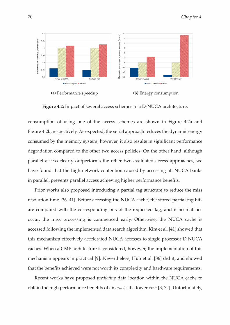
70 Chapter 4.
(a) Performance speedup (b) Energy consumption
Figure 4.2: Impact of several access schemes in a D-NUCA architecture.
consumption of using one of the access schemes are shown in Figure 4.2a and
Figure 4.2b, respectively. As expected, the serial approach reduces the dynamic energy
consumed by the memory system; however, it also results in significant performance
degradation compared to the other two access policies. On the other hand, although
parallel access clearly outperforms the other two evaluated access approaches, we
have found that the high network contention caused by accessing all NUCA banks
in parallel, prevents parallel access achieving higher performance benefits.
Prior works also proposed introducing a partial tag structure to reduce the miss
resolution time [36, 41]. Before accessing the NUCA cache, the stored partial tag bits
are compared with the corresponding bits of the requested tag, and if no matches
occur, the miss processing is commenced early. Otherwise, the NUCA cache is
accessed following the implemented data search algorithm. Kim et al. [41] showed that
this mechanism effectively accelerated NUCA accesses to single-processor D-NUCA
caches. When a CMP architecture is considered, however, the implementation of this
mechanism appears impractical [9]. Nevertheless, Huh et al. [36] did it, and showed
that the benefits achieved were not worth its complexity and hardware requirements.
Recent works have proposed predicting data location within the NUCA cache to
obtain the high performance benefits of an oracle at a lower cost [3, 72]. Unfortunately,
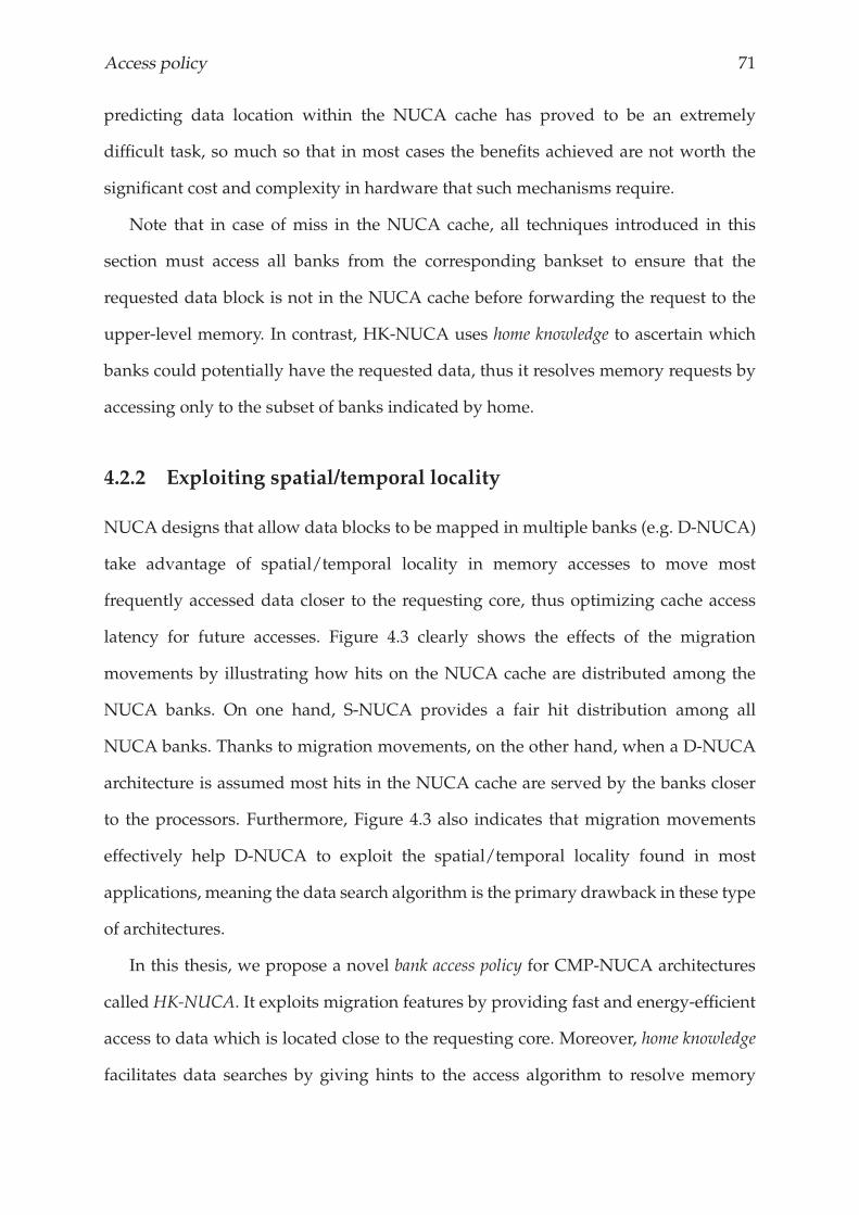
Access policy 71
predicting data location within the NUCA cache has proved to be an extremely
difficult task, so much so that in most cases the benefits achieved are not worth the
significant cost and complexity in hardware that such mechanisms require.
Note that in case of miss in the NUCA cache, all techniques introduced in this
section must access all banks from the corresponding bankset to ensure that the
requested data block is not in the NUCA cache before forwarding the request to the
upper-level memory. In contrast, HK-NUCA uses home knowledge to ascertain which
banks could potentially have the requested data, thus it resolves memory requests by
accessing only to the subset of banks indicated by home.
4.2.2 Exploiting spatial/temporal locality
NUCA designs that allow data blocks to be mapped in multiple banks (e.g. D-NUCA)
take advantage of spatial/temporal locality in memory accesses to move most
frequently accessed data closer to the requesting core, thus optimizing cache access
latency for future accesses. Figure 4.3 clearly shows the effects of the migration
movements by illustrating how hits on the NUCA cache are distributed among the
NUCA banks. On one hand, S-NUCA provides a fair hit distribution among all
NUCA banks. Thanks to migration movements, on the other hand, when a D-NUCA
architecture is assumed most hits in the NUCA cache are served by the banks closer
to the processors. Furthermore, Figure 4.3 also indicates that migration movements
effectively help D-NUCA to exploit the spatial/temporal locality found in most
applications, meaning the data search algorithm is the primary drawback in these type
of architectures.
In this thesis, we propose a novel bank access policy for CMP-NUCA architectures
called HK-NUCA. It exploits migration features by providing fast and energy-efficient
access to data which is located close to the requesting core. Moreover, home knowledge
facilitates data searches by giving hints to the access algorithm to resolve memory
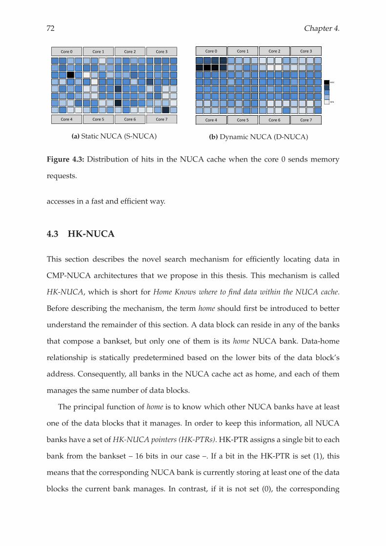
72 Chapter 4.
Core 0 Core 1 Core 2 Core 3
Core 4 Core 5 Core 6 Core 7
(a) Static NUCA (S-NUCA)
Core 0 Core 1 Core 2 Core 3
Core 4 Core 5 Core 6 Core 7
(b) Dynamic NUCA (D-NUCA)
MAX
MIN
Figure 4.3: Distribution of hits in the NUCA cache when the core 0 sends memory
requests.
accesses in a fast and efficient way.
4.3 HK-NUCA
This section describes the novel search mechanism for efficiently locating data in
CMP-NUCA architectures that we propose in this thesis. This mechanism is called
HK-NUCA, which is short for Home Knows where to find data within the NUCA cache.
Before describing the mechanism, the term home should first be introduced to better
understand the remainder of this section. A data block can reside in any of the banks
that compose a bankset, but only one of them is its home NUCA bank. Data-home
relationship is statically predetermined based on the lower bits of the data block’s
address. Consequently, all banks in the NUCA cache act as home, and each of them
manages the same number of data blocks.
The principal function of home is to know which other NUCA banks have at least
one of the data blocks that it manages. In order to keep this information, all NUCA
banks have a set of HK-NUCA pointers (HK-PTRs). HK-PTR assigns a single bit to each
bank from the bankset – 16 bits in our case –. If a bit in the HK-PTR is set (1), this
means that the corresponding NUCA bank is currently storing at least one of the data
blocks the current bank manages. In contrast, if it is not set (0), the corresponding
Access policy 73
Core 0 Core 1 Core 2 Core 3
0 1 2 3
Core 0 Core 1 Core 2 Core 3
8 9 10 11
12 13 14 15
4 5 6 74 5 6 7
Core 4 Core 5 Core 6 Core 7
(a) Fast access
Core 0 Core 1 Core 2 Core 3
0 1 2 3
Core 0 Core 1 Core 2 Core 3
8 9 10 11
12 13 14 15
HK PTR:
0 0 1 0 1 1 0 0 0 0 0 0 1 0 1 0
4 5 6 74 5 6 7
Core 4 Core 5 Core 6 Core 7
(b) Call homeCore 0 Core 1 Core 2 Core 3
0 1 2 3
Core 0 Core 1 Core 2 Core 3
8 9 10 11
12 13 14 15
4 5 6 74 5 6 7
Core 4 Core 5 Core 6 Core 7
(c) Parallel access
Figure 4.4: Scheme of HK-NUCA data search mechanism.
NUCA bank does not have any data blocks from the current home bank. There is a
HK-PTR for each cache-set in the NUCA bank. We find that pointing at the cache-set
level significantly increases the global accuracy of HK-NUCA by reducing the total
amount of 1’s per HK-PTR.
This mechanism, based on the knowledge of home banks, significantly reduces
on-chip network traffic as well as the miss resolution time, and consequently provides
faster and more efficient accesses to the NUCA cache. The following section describes
how HK-NUCA search mechanism works, Section 4.3.2 details HK-PTR management
tasks, and Section 4.3.3 introduces the implementation details.
4.3.1 How HK-NUCA works
After getting a miss in a private first-level cache from any core, the NUCA cache is
probed by means of the bank access policy that we propose in this thesis. HK-NUCA
consists of the following three stages: 1) Fast access, 2) Call home, and 3) Parallel access.
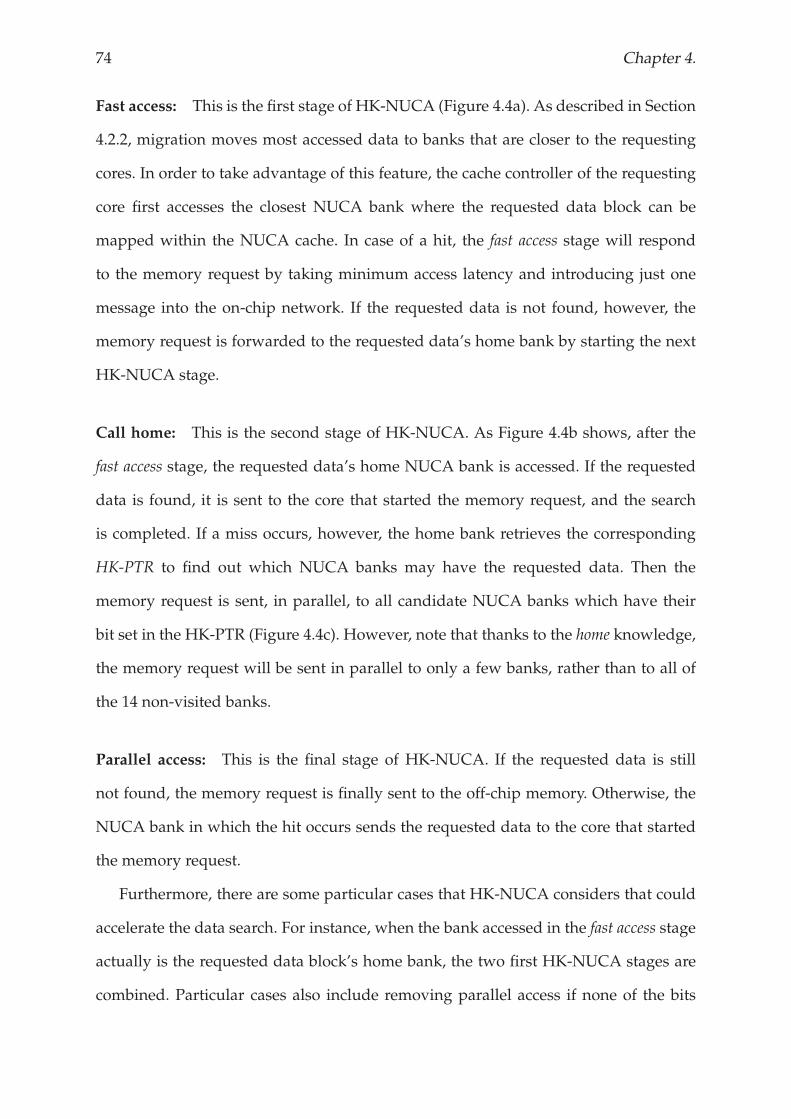
74 Chapter 4.
Fast access: This is the first stage of HK-NUCA (Figure 4.4a). As described in Section
4.2.2, migration moves most accessed data to banks that are closer to the requesting
cores. In order to take advantage of this feature, the cache controller of the requesting
core first accesses the closest NUCA bank where the requested data block can be
mapped within the NUCA cache. In case of a hit, the fast access stage will respond
to the memory request by taking minimum access latency and introducing just one
message into the on-chip network. If the requested data is not found, however, the
memory request is forwarded to the requested data’s home bank by starting the next
HK-NUCA stage.
Call home: This is the second stage of HK-NUCA. As Figure 4.4b shows, after the
fast access stage, the requested data’s home NUCA bank is accessed. If the requested
data is found, it is sent to the core that started the memory request, and the search
is completed. If a miss occurs, however, the home bank retrieves the corresponding
HK-PTR to find out which NUCA banks may have the requested data. Then the
memory request is sent, in parallel, to all candidate NUCA banks which have their
bit set in the HK-PTR (Figure 4.4c). However, note that thanks to the home knowledge,
the memory request will be sent in parallel to only a few banks, rather than to all of
the 14 non-visited banks.
Parallel access: This is the final stage of HK-NUCA. If the requested data is still
not found, the memory request is finally sent to the off-chip memory. Otherwise, the
NUCA bank in which the hit occurs sends the requested data to the core that started
the memory request.
Furthermore, there are some particular cases that HK-NUCA considers that could
accelerate the data search. For instance, when the bank accessed in the fast access stage
actually is the requested data block’s home bank, the two first HK-NUCA stages are
combined. Particular cases also include removing parallel access if none of the bits
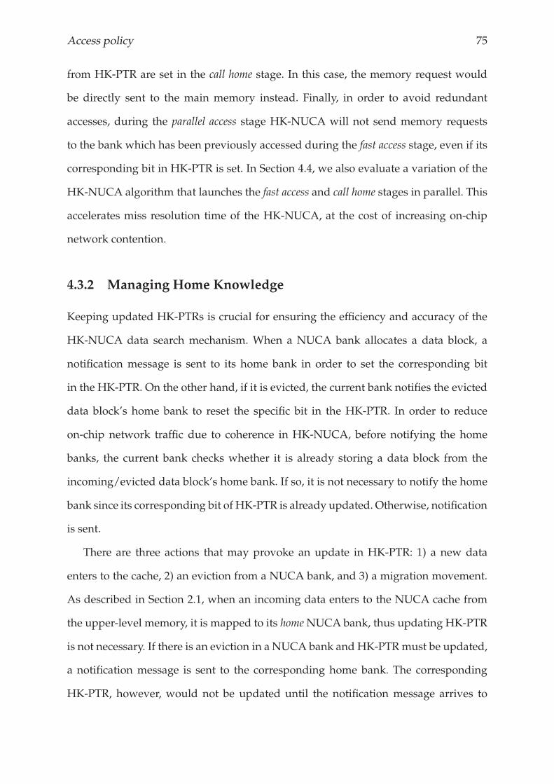
Access policy 75
from HK-PTR are set in the call home stage. In this case, the memory request would
be directly sent to the main memory instead. Finally, in order to avoid redundant
accesses, during the parallel access stage HK-NUCA will not send memory requests
to the bank which has been previously accessed during the fast access stage, even if its
corresponding bit in HK-PTR is set. In Section 4.4, we also evaluate a variation of the
HK-NUCA algorithm that launches the fast access and call home stages in parallel. This
accelerates miss resolution time of the HK-NUCA, at the cost of increasing on-chip
network contention.
4.3.2 Managing Home Knowledge
Keeping updated HK-PTRs is crucial for ensuring the efficiency and accuracy of the
HK-NUCA data search mechanism. When a NUCA bank allocates a data block, a
notification message is sent to its home bank in order to set the corresponding bit
in the HK-PTR. On the other hand, if it is evicted, the current bank notifies the evicted
data block’s home bank to reset the specific bit in the HK-PTR. In order to reduce
on-chip network traffic due to coherence in HK-NUCA, before notifying the home
banks, the current bank checks whether it is already storing a data block from the
incoming/evicted data block’s home bank. If so, it is not necessary to notify the home
bank since its corresponding bit of HK-PTR is already updated. Otherwise, notification
is sent.
There are three actions that may provoke an update in HK-PTR: 1) a new data
enters to the cache, 2) an eviction from a NUCA bank, and 3) a migration movement.
As described in Section 2.1, when an incoming data enters to the NUCA cache from
the upper-level memory, it is mapped to its homeNUCA bank, thus updating HK-PTR
is not necessary. If there is an eviction in a NUCA bank and HK-PTRmust be updated,
a notification message is sent to the corresponding home bank. The corresponding
HK-PTR, however, would not be updated until the notification message arrives to
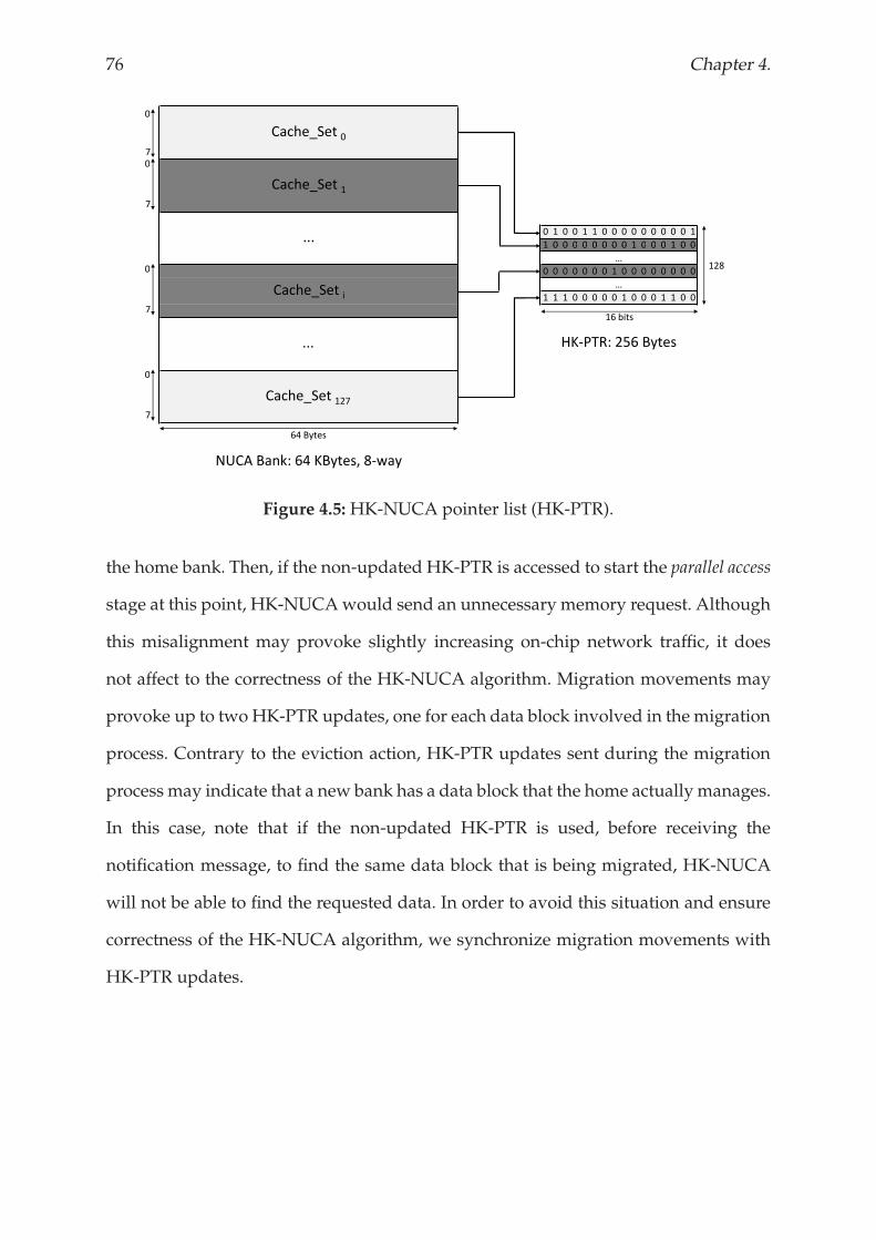
76 Chapter 4.
0 1 0 0 1 1 0 0 0 0 0 0 0 0 0 1
1 0 0 0 0 0 0 0 0 1 0 0 0 1 0 0
0
7
0
7
Cache_Set 0
Cache_Set 1
...1 0 0 0 0 0 0 0 0 1 0 0 0 1 0 0
0 0 0 0 0 0 0 1 0 0 0 0 0 0 0 0
1 1 1 0 0 0 0 0 1 0 0 0 1 1 0 0
NUCA Bank: 64 KBytes, 8 way
…
…
0
7
0
7
Cache_Set i
...
Cache_Set 127
64 Bytes
128
16 bits
HK PTR: 256 Bytes
Figure 4.5:HK-NUCA pointer list (HK-PTR).
the home bank. Then, if the non-updated HK-PTR is accessed to start the parallel access
stage at this point, HK-NUCAwould send an unnecessary memory request. Although
this misalignment may provoke slightly increasing on-chip network traffic, it does
not affect to the correctness of the HK-NUCA algorithm. Migration movements may
provoke up to two HK-PTR updates, one for each data block involved in the migration
process. Contrary to the eviction action, HK-PTR updates sent during the migration
process may indicate that a new bank has a data block that the home actually manages.
In this case, note that if the non-updated HK-PTR is used, before receiving the
notification message, to find the same data block that is being migrated, HK-NUCA
will not be able to find the requested data. In order to avoid this situation and ensure
correctness of the HK-NUCA algorithm, we synchronize migration movements with
HK-PTR updates.
Access policy 77
4.3.3 Implementing HK-NUCA
HK-NUCA requires introducing some additional hardware to implement HK-PTRs.
Figure 4.5 shows that HK-PTR needs 256 bytes per NUCA bank, so assuming that our
8 MByte-NUCA cache consists of 128 banks, the total hardware required by HK-PTRs
is 32 KBytes which is less than 0.4% of hardware overhead. Apart from hardware
overhead due to HK-PTRs, HK-NUCA also introduces some complexity in the NUCA
design (e.g. comparators), but their timing effects are hidden by the critical path.
These implementation overheads (hardware and design complexity), however, are
accurately modeled in our experimental evaluation, therefore the results shown in
Section 4.4 already take these issues into consideration.
Although HK-NUCA is proposed in a heavy-banked NUCA cache, this is not the
only organization it can work with. HK-NUCA, for instance, can be easily adapted
to a 4x4 tiled-CMP architecture – similar to that assumed in some recent works in
the literature [32, 59, 30]–. As with the heavy-banked architecture, the 4x4 tiled-CMP
allows a data block to be mapped in 16 positions within the NUCA cache. In this case,
HK-PTRs are as big as with our baseline, so the extra hardware required would be
the same. Moreover, we believe that the benefits in terms of performance and energy
consumption obtained using HK-NUCA on the tiled architecture would be similar to
that achieved with our baseline because both architectures are D-NUCA designs.
4.4 RESULTS AND ANALYSIS
The primary characteristics of HK-NUCAmake it a promising data search mechanism
that not only boosts performance, but also reduces energy consumption. On one hand,
by taking advantage of migration movements, the fast access stage of HK-NUCA
provides high performance at a minimum cost. Home knowledge, on the other hand,
allows memory requests to be satisfied by only accessing the NUCA banks that
can potentially have the requested data. With that, HK-NUCA significantly reduces
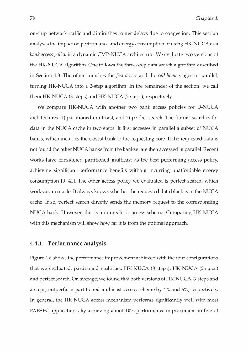
78 Chapter 4.
on-chip network traffic and diminishes router delays due to congestion. This section
analyses the impact on performance and energy consumption of using HK-NUCA as a
bank access policy in a dynamic CMP-NUCA architecture. We evaluate two versions of
the HK-NUCA algorithm. One follows the three-step data search algorithm described
in Section 4.3. The other launches the fast access and the call home stages in parallel,
turning HK-NUCA into a 2-step algorithm. In the remainder of the section, we call
them HK-NUCA (3-steps) and HK-NUCA (2-steps), respectively.
We compare HK-NUCA with another two bank access policies for D-NUCA
architectures: 1) partitioned multicast, and 2) perfect search. The former searches for
data in the NUCA cache in two steps. It first accesses in parallel a subset of NUCA
banks, which includes the closest bank to the requesting core. If the requested data is
not found the other NUCAbanks from the bankset are then accessed in parallel. Recent
works have considered partitioned multicast as the best performing access policy,
achieving significant performance benefits without incurring unaffordable energy
consumption [9, 41]. The other access policy we evaluated is perfect search, which
works as an oracle. It always knows whether the requested data block is in the NUCA
cache. If so, perfect search directly sends the memory request to the corresponding
NUCA bank. However, this is an unrealistic access scheme. Comparing HK-NUCA
with this mechanism will show how far it is from the optimal approach.
4.4.1 Performance analysis
Figure 4.6 shows the performance improvement achieved with the four configurations
that we evaluated: partitioned multicast, HK-NUCA (3-steps), HK-NUCA (2-steps)
and perfect search. On average, we found that both versions of HK-NUCA, 3-steps and
2-steps, outperform partitioned multicast access scheme by 4% and 6%, respectively.
In general, the HK-NUCA access mechanism performs significantly well with most
PARSEC applications, by achieving about 10% performance improvement in five of
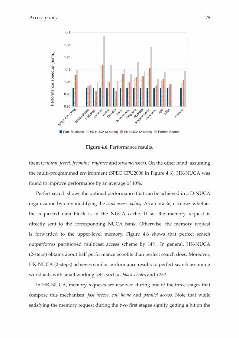
Access policy 79
Figure 4.6: Performance results.
them (canneal, ferret, freqmine, raytrace and streamcluster). On the other hand, assuming
the multi-programmed environment (SPEC CPU2006 in Figure 4.6), HK-NUCA was
found to improve performance by an average of 10%.
Perfect search shows the optimal performance that can be achieved in a D-NUCA
organization by only modifying the bank access policy. As an oracle, it knows whether
the requested data block is in the NUCA cache. If so, the memory request is
directly sent to the corresponding NUCA bank. Otherwise, the memory request
is forwarded to the upper-level memory. Figure 4.6 shows that perfect search
outperforms partitioned multicast access scheme by 14%. In general, HK-NUCA
(2-steps) obtains about half performance benefits than perfect search does. Moreover,
HK-NUCA (2-steps) achieves similar performance results to perfect search assuming
workloads with small working sets, such as blackscholes and x264.
In HK-NUCA, memory requests are resolved during one of the three stages that
compose this mechanism: fast access, call home and parallel access. Note that while
satisfying the memory request during the two first stages signify getting a hit on the
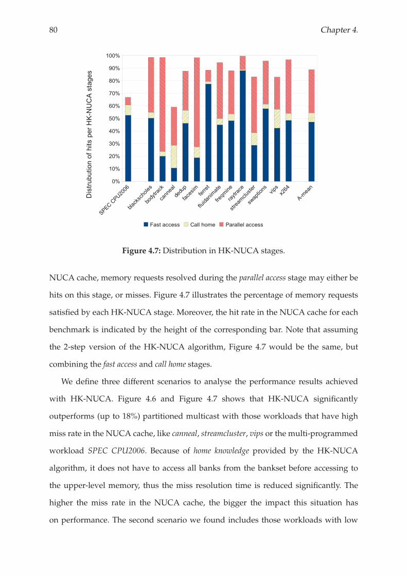
80 Chapter 4.
Figure 4.7: Distribution in HK-NUCA stages.
NUCA cache, memory requests resolved during the parallel access stage may either be
hits on this stage, or misses. Figure 4.7 illustrates the percentage of memory requests
satisfied by each HK-NUCA stage. Moreover, the hit rate in the NUCA cache for each
benchmark is indicated by the height of the corresponding bar. Note that assuming
the 2-step version of the HK-NUCA algorithm, Figure 4.7 would be the same, but
combining the fast access and call home stages.
We define three different scenarios to analyse the performance results achieved
with HK-NUCA. Figure 4.6 and Figure 4.7 shows that HK-NUCA significantly
outperforms (up to 18%) partitioned multicast with those workloads that have high
miss rate in the NUCA cache, like canneal, streamcluster, vips or the multi-programmed
workload SPEC CPU2006. Because of home knowledge provided by the HK-NUCA
algorithm, it does not have to access all banks from the bankset before accessing to
the upper-level memory, thus the miss resolution time is reduced significantly. The
higher the miss rate in the NUCA cache, the bigger the impact this situation has
on performance. The second scenario we found includes those workloads with low
Access policy 81
miss rate in the NUCA cache, but high rate (50% or more) of hits resolved during
the first two stages (fast access and call home): e.g. dedup, raytrace, swaptions, or x264.
Both partitioned multicast and HK-NUCA take similar access latencies to satisfy
memory requests when they hit on the closest NUCA bank. While the former accesses
this bank during its first step, HK-NUCA accesses it during the fast access stage.
Thus, partitioned multicast introduces nine messages to the on-chip network, whereas
HK-NUCA needs just one (or two with the 2-steps version). Therefore, HK-NUCA
reduces on-chip network traffic and diminishes router delays due to congestion which
result to be key factors to outperform (by 5%) partitioned multicast in this scenario.
The third scenario is composed of bodytrack and facesim. In this case, HK-NUCA
achieves 4% performance loss compared to the partitioned multicast scheme. The
principal characteristics of this scenario are, on one hand, very high hit rate in the
NUCA cache (close to 99%) and, on the other hand, most of memory requests resolved
during the parallel access stage. As partitioned multicast sends the memory request to
nine banks in parallel during its first stage, it resolves memory requests faster than
HK-NUCA when the requested data is in the central banks. HK-NUCA, however,
would satisfy these request during the second or the third step of the algorithm,
depending on the version of HK-NUCA assumed. Besides, the whole working set
fits in the NUCA cache, so HK-NUCA can not benefit of the reduction on the miss
resolution time. Fortunately, the trend on the applications for future processors follows
the characteristics of the first scenario: applications with large working set or multiple
applications running simulatenously.
The effectiveness of HK-NUCA relies on the accuracy of the HK-PTRs, in other
words, the number of messages required to resolve a memory request during the
parallel access stage. Table 4.1 shows that, on average, 85% of memory request resolved
during the parallel access stage required up to 5 messages, which is far away from
the most pessimistic situation: 14 messages. We also highlight that the accuracy of
HK-NUCA remains constant with all simulated workloads, although their memory
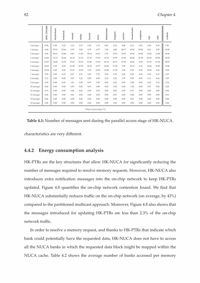
82 Chapter 4.
SPEC
CPU2006
black
scholes
bodytrack
canneal
dedup
facesim
ferret
fluidanim
ate
freqmine
raytrace
streamcluster
swaptions
vips
x264
A-M
ean
0 messages 0.94 0.38 0.22 0.12 0.73 0.22 1.10 0.81 0.32 0.48 0.21 0.52 0.36 0.45 0.41
1 message 4.84 33.01 23.66 2.79 3.58 8.75 6.77 1.85 4.98 28.17 10.00 38.04 4.01 4.55 12.80
2 messages 9.56 39.61 33.86 8.45 11.09 18.14 14.31 3.76 15.16 19.99 18.96 36.90 12.82 13.28 19.68
3 messages 14.49 12.13 25.04 16.34 21.33 21.19 17.92 14.35 19.97 19.69 20.68 16.78 20.63 22.96 19.29
4 messages 18.27 14.60 12.10 21.87 25.93 21.80 17.63 24.19 22.13 15.94 12.05 5.90 21.93 31.54 18.83
5 messages 18.69 0.25 4.04 21.00 20.53 16.18 14.77 22.96 17.38 7.00 10.13 1.26 18.64 18.02 13.06
6 messages 15.24 0.03 0.86 15.51 10.93 9.30 10.93 18.82 11.78 3.44 9.52 0.29 12.64 6.26 8.38
7 messages 9.92 0.00 0.15 8.67 4.31 3.51 7.93 9.92 5.32 2.40 8.20 0.20 6.32 2.15 4.51
8 messages 5.13 0.00 0.05 3.67 1.23 0.83 4.98 2.43 2.03 1.97 5.59 0.09 2.11 0.62 1.97
9 messages 2.09 0.00 0.02 1.21 0.28 0.07 2.50 0.69 0.67 0.87 2.98 0.02 0.47 0.14 0.76
10 messages 0.66 0.00 0.00 0.30 0.06 0.01 0.88 0.18 0.18 0.04 1.22 0.00 0.07 0.02 0.24
11 messages 0.15 0.00 0.00 0.06 0.01 0.00 0.23 0.03 0.05 0.00 0.37 0.00 0.00 0.00 0.06
12 messages 0.02 0.00 0.00 0.01 0.00 0.00 0.04 0.00 0.01 0.00 0.08 0.00 0.00 0.00 0.01
13 messages 0.00 0.00 0.00 0.00 0.00 0.00 0.00 0.00 0.00 0.00 0.01 0.00 0.00 0.00 0.00
14 messages 0.00 0.00 0.00 0.00 0.00 0.00 0.00 0.00 0.00 0.00 0.00 0.00 0.00 0.00 0.00
Values in percentage (%)
Table 4.1:Number of messages sent during the parallel access stage of HK-NUCA.
characteristics are very different.
4.4.2 Energy consumption analysis
HK-PTRs are the key structures that allow HK-NUCA for significantly reducing the
number of messages required to resolve memory requests. However, HK-NUCA also
introduces extra notification messages into the on-chip network to keep HK-PTRs
updated. Figure 4.8 quantifies the on-chip network contention found. We find that
HK-NUCA substantially reduces traffic on the on-chip network (on average, by 43%)
compared to the partitioned multicast approach. Moreover, Figure 4.8 also shows that
the messages introduced for updating HK-PTRs are less than 2.3% of the on-chip
network traffic.
In order to resolve a memory request, and thanks to HK-PTRs that indicate which
bank could potentially have the requested data, HK-NUCA does not have to access
all the NUCA banks in which the requested data block might be mapped within the
NUCA cache. Table 4.2 shows the average number of banks accessed per memory
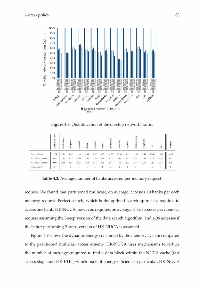
Access policy 83
Figure 4.8: Quantification of the on-chip network traffic.
SPECCPU2006
black
scholes
bodytrack
canneal
dedup
facesim
ferret
fluidanim
ate
freqmine
raytrace
streamcluster
swaptions
vips
x264
A-M
ean
Part. multicast 11.24 9.82 9.49 11.66 9.99 9.87 9.95 10.33 10.06 9.11 11.04 9.53 10.66 10.12 10.03
HK-NUCA (3-steps) 3.67 2.61 3.78 5.53 3.91 4.53 2.49 4.13 3.86 1.51 4.57 2.63 4.09 3.52 3.82
HK-NUCA (2-steps) 4.09 2.95 3.85 5.57 4.03 4.65 3.05 4.51 4.09 2.33 4.71 2.86 4.19 3.77 4.06
Perfect Search 1 1 1 1 1 1 1 1 1 1 1 1 1 1 1
Table 4.2: Average number of banks accessed per memory request.
request. We found that partitioned multicast, on average, accesses 10 banks per each
memory request. Perfect search, which is the optimal search approach, requires to
access one bank. HK-NUCA, however, requires, on average, 3.82 accesses per memory
request assuming the 3-step version of the data search algorithm, and 4.06 accesses if
the better-performing 2-steps version of HK-NUCA is assumed.
Figure 4.9 shows the dynamic energy consumed by the memory system compared
to the partitioned multicast access scheme. HK-NUCA uses mechanisms to reduce
the number of messages required to find a data block within the NUCA cache (fast
access stage and HK-PTRs) which make it energy efficient. In particular, HK-NUCA
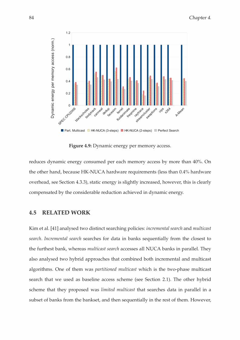
84 Chapter 4.
Figure 4.9: Dynamic energy per memory access.
reduces dynamic energy consumed per each memory access by more than 40%. On
the other hand, because HK-NUCA hardware requirements (less than 0.4% hardware
overhead, see Section 4.3.3), static energy is slightly increased, however, this is clearly
compensated by the considerable reduction achieved in dynamic energy.
4.5 RELATED WORK
Kim et al. [41] analysed two distinct searching policies: incremental search andmulticast
search. Incremental search searches for data in banks sequentially from the closest to
the furthest bank, whereas multicast search accesses all NUCA banks in parallel. They
also analysed two hybrid approaches that combined both incremental and multicast
algorithms. One of them was partitioned multicast which is the two-phase multicast
search that we used as baseline access scheme (see Section 2.1). The other hybrid
scheme that they proposed was limited multicast that searches data in parallel in a
subset of banks from the bankset, and then sequentially in the rest of them. However,
Access policy 85
hybrid approaches that try to keep the best of both worlds are still far from ideal.
One orthogonal way to improve any of the searching algorithms is to introduce tag
information replication along the NUCA cache [30, 36, 39, 72]. Unfortunately, these
approaches lead to increased access time, energy consumption and die area.
A novel bank access approach which predicts the bank in which data are most
likely to be located has been proposed by Akioka et al. [3]. They divided the NUCA
cache into rings to denote a set of banks that exhibit the same access latency and
introduced a Last Access Based (LAB) scheme. This approach first accesses the ring
that satisfied the previous request for the same data. They showed that, compared
with parallel and serial access, LAB reduces energy consumption while maintaining
similar performance. However, an accurate implementation is not addressed in terms
of die area and access time. Ricci et al. [72] also dealed with prediction by identifying
cache bank candidates with high accuracy through Bloom filters. The underlying idea
is to keep approximate information about the contents of banks. Preliminary results
show that compared to a simple D-NUCAapproach the number of messages inside the
cache network decreases while the hit ratio accuracy is maintained. Unfortunately, the
work focuses on demonstrating the potential and an implementation of the approach
is not presented, nor is an analysis of performance or energy consumption.
Recent works have proposed NUCA designs based on S-NUCA, but redefining
placement decisions to be able to locate data in multiple banks within the NUCA
cache [32, 19]. These designs intend to have the best of the two worlds, locality from a
D-NUCA design and the simplicity found in S-NUCA.However, they rely on complex
OS-assisted data placement schemes.
Muralimanohar et al. [63] focused on the network on-chip design to alleviate
the interconnect delay bottleneck. They proposed a NUCA approach that uses two
different physical wires to build NUCA architectures (one of these wires provided
lower latency and the other provided wider bandwidth). Then, they proposed two
different bank searching algorithms (early and aggressive lookup) that benefits from
86 Chapter 4.
this novel interconnection design.
A different approach was introduced by Bolotin et al. [14]. They focused on
implementing low cost mechanism on a Network-on-Chip (NoC) for supporting
efficient NUCA caches. The idea was to build a priority mechanism which
differentiates between short control messages and long data messages. Particularly,
they prioritize short messages that belongs to the access mechanism of a D-NUCA
cache to boost its performance.
4.6 CONCLUSIONS
Although exploiting flexible mapping D-NUCA promises significant benefits, those
benefits are restricted by the access algorithm used. Previous works agree that the
simplest design is probably the best: S-NUCA [9, 36, 41]. However, D-NUCA still
holds promise and it is worth waiting for an efficient access scheme that allows it to
make the promised benefits a reality. This is HK-NUCA. It does not only improve
performance, but also energy consumption. On one hand, by taking advantage of
migration movements, the fast access stage of HK-NUCA provides high-performance
at a minimum cost. Home knowledge, on the other hand, allows memory requests to be
satisfied by only accessing the NUCA banks that could potentially have the requested
data. This means that HK-NUCA significantly reduces on-chip network traffic and
diminishes router delays due to congestion. On average, HK-NUCA outperforms
previous access schemes for D-NUCA caches by 6%, and reduces the dynamic energy
consumed by the memory system by 40%.
Chapter 5
Placement policy
This chapter presents the implementation of a hybrid NUCA cache using two different memory
technologies: SRAM and eDRAM. We propose using a smart placement policy in the hybrid
NUCA cache that enables both technologies to cooperate in order to emphasize their strengths
and hide their drawbacks.

Placement policy 89
5.1 INTRODUCTION
SRAM memories are typically used to implement on-chip cache memories because
they are faster and easier to integrate than other memories, thus they leverage
performance. DRAM memories, however, leverage density. Therefore, this technology
has been traditionally used to implement off-chip memories. Advances in technology
allowed for integrating DRAM-like structures into the chip, called embedded DRAM
(eDRAM). This technology has already been successfully implemented in some GPUs
and other graphic-intensive SoC, like game consoles. The most recent processor from
IBM®, POWER7, is the first general-purpose processor that integrates an eDRAM
module on the chip [81]. POWER7 uses eDRAM technology to implement a shared
32MByte-L3 cache. By using eDRAM instead of SRAM, POWER7 increases access
latency in its third-level cache by few cycles, however, eDRAM provides a roughly
3x density improvement as well as about 3.5x lower energy consumption than an
equivalent SRAM implementation. Besides, this could be considered the starting point
to integrate more sophisticated hybrid cache structures on the chip in the near future.
In this thesis we propose a hybrid NUCA cache that is composed of SRAM banks
and eDRAM banks. We demonstrate, that due to the high locality found in emerging
applications, a high percentage of data that enters to the on-chip last-level cache are
not accessed again before they are replaced. Based on this observation, we propose
a placement scheme where re-accessed data blocks are stored in fast, but costly in
terms of area and power, SRAM banks, while eDRAMbanks store data blocks that just
arrive to the NUCA cache or were demoted from a SRAM bank. The effectiveness of
this architecture is demonstrated further in this chapter. We show that a well-balanced
SRAM / eDRAM NUCA cache can achieve similar performance results than using a
NUCA cache composed of only SRAM banks, but reducing area by 15% and power
consumed by 10%.
The remainder of this chapter is structured as follows. Section 5.2 describes the
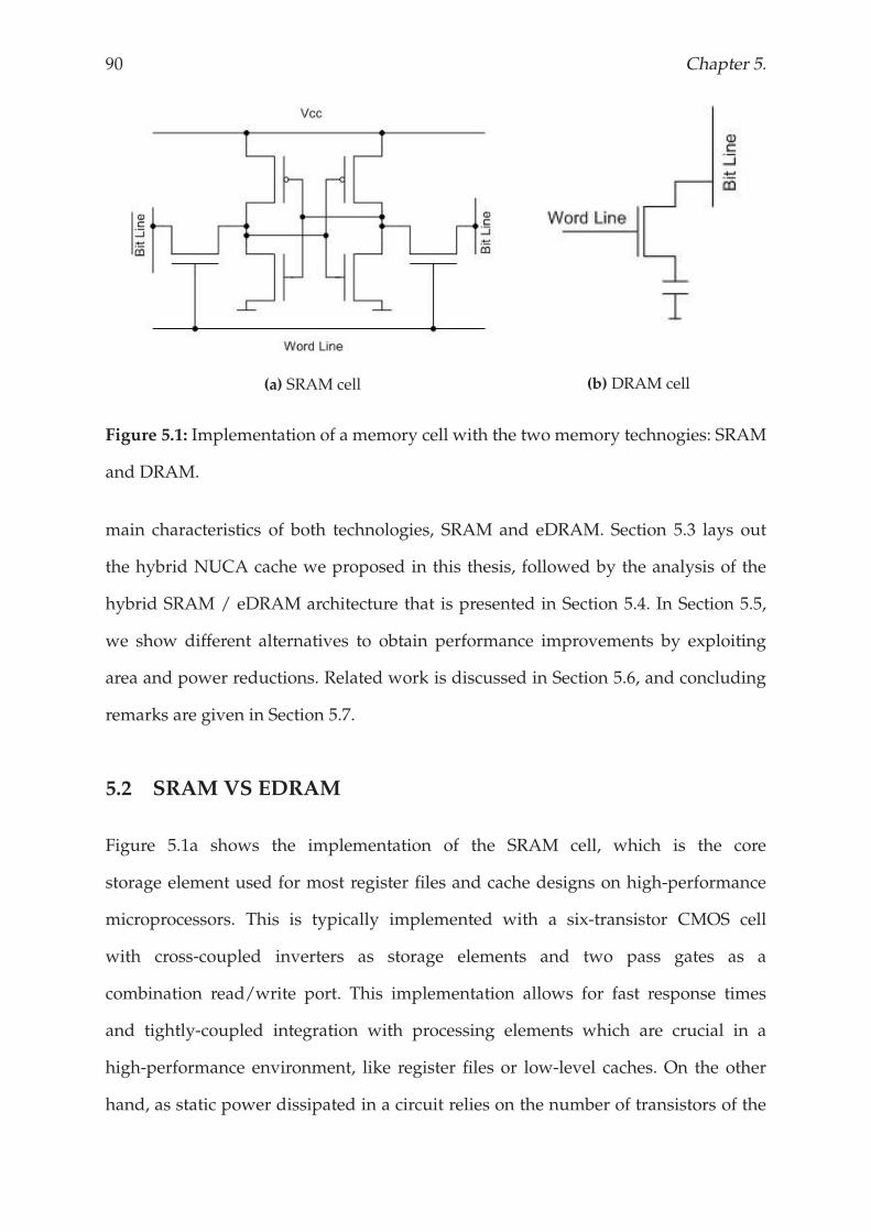
90 Chapter 5.
(a) SRAM cell (b) DRAM cell
Figure 5.1: Implementation of a memory cell with the two memory technogies: SRAM
and DRAM.
main characteristics of both technologies, SRAM and eDRAM. Section 5.3 lays out
the hybrid NUCA cache we proposed in this thesis, followed by the analysis of the
hybrid SRAM / eDRAM architecture that is presented in Section 5.4. In Section 5.5,
we show different alternatives to obtain performance improvements by exploiting
area and power reductions. Related work is discussed in Section 5.6, and concluding
remarks are given in Section 5.7.
5.2 SRAM VS EDRAM
Figure 5.1a shows the implementation of the SRAM cell, which is the core
storage element used for most register files and cache designs on high-performance
microprocessors. This is typically implemented with a six-transistor CMOS cell
with cross-coupled inverters as storage elements and two pass gates as a
combination read/write port. This implementation allows for fast response times
and tightly-coupled integration with processing elements which are crucial in a
high-performance environment, like register files or low-level caches. On the other
hand, as static power dissipated in a circuit relies on the number of transistors of the
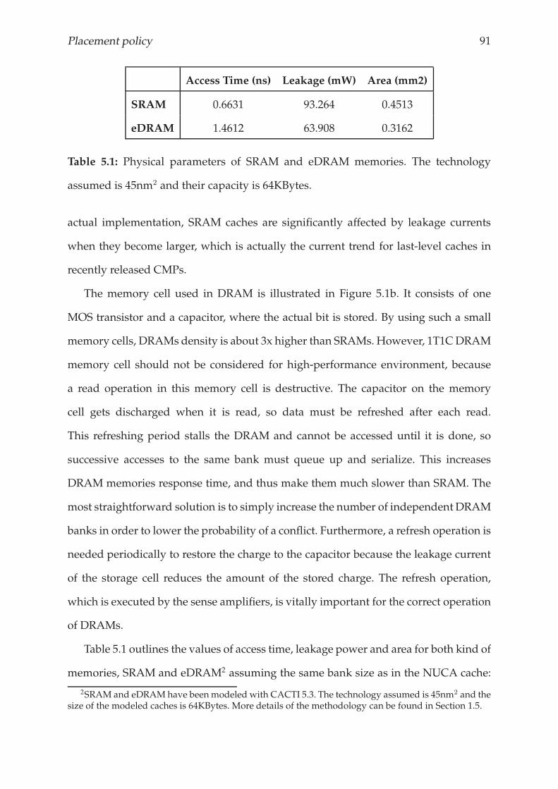
Placement policy 91
Access Time (ns) Leakage (mW) Area (mm2)
SRAM 0.6631 93.264 0.4513
eDRAM 1.4612 63.908 0.3162
Table 5.1: Physical parameters of SRAM and eDRAM memories. The technology
assumed is 45nm2 and their capacity is 64KBytes.
actual implementation, SRAM caches are significantly affected by leakage currents
when they become larger, which is actually the current trend for last-level caches in
recently released CMPs.
The memory cell used in DRAM is illustrated in Figure 5.1b. It consists of one
MOS transistor and a capacitor, where the actual bit is stored. By using such a small
memory cells, DRAMs density is about 3x higher than SRAMs. However, 1T1CDRAM
memory cell should not be considered for high-performance environment, because
a read operation in this memory cell is destructive. The capacitor on the memory
cell gets discharged when it is read, so data must be refreshed after each read.
This refreshing period stalls the DRAM and cannot be accessed until it is done, so
successive accesses to the same bank must queue up and serialize. This increases
DRAM memories response time, and thus make them much slower than SRAM. The
most straightforward solution is to simply increase the number of independent DRAM
banks in order to lower the probability of a conflict. Furthermore, a refresh operation is
needed periodically to restore the charge to the capacitor because the leakage current
of the storage cell reduces the amount of the stored charge. The refresh operation,
which is executed by the sense amplifiers, is vitally important for the correct operation
of DRAMs.
Table 5.1 outlines the values of access time, leakage power and area for both kind of
memories, SRAM and eDRAM2 assuming the same bank size as in the NUCA cache:
2SRAM and eDRAMhave beenmodeled with CACTI 5.3. The technology assumed is 45nm2 and thesize of the modeled caches is 64KBytes. More details of the methodology can be found in Section 1.5.
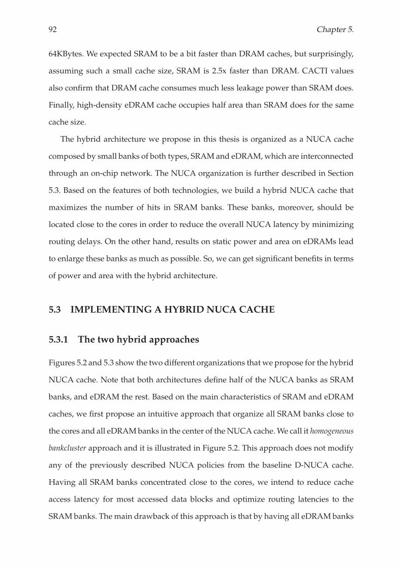
92 Chapter 5.
64KBytes. We expected SRAM to be a bit faster than DRAM caches, but surprisingly,
assuming such a small cache size, SRAM is 2.5x faster than DRAM. CACTI values
also confirm that DRAM cache consumes much less leakage power than SRAM does.
Finally, high-density eDRAM cache occupies half area than SRAM does for the same
cache size.
The hybrid architecture we propose in this thesis is organized as a NUCA cache
composed by small banks of both types, SRAM and eDRAM,which are interconnected
through an on-chip network. The NUCA organization is further described in Section
5.3. Based on the features of both technologies, we build a hybrid NUCA cache that
maximizes the number of hits in SRAM banks. These banks, moreover, should be
located close to the cores in order to reduce the overall NUCA latency by minimizing
routing delays. On the other hand, results on static power and area on eDRAMs lead
to enlarge these banks as much as possible. So, we can get significant benefits in terms
of power and area with the hybrid architecture.
5.3 IMPLEMENTINGA HYBRID NUCA CACHE
5.3.1 The two hybrid approaches
Figures 5.2 and 5.3 show the two different organizations that we propose for the hybrid
NUCA cache. Note that both architectures define half of the NUCA banks as SRAM
banks, and eDRAM the rest. Based on the main characteristics of SRAM and eDRAM
caches, we first propose an intuitive approach that organize all SRAM banks close to
the cores and all eDRAMbanks in the center of the NUCA cache.We call it homogeneous
bankcluster approach and it is illustrated in Figure 5.2. This approach does not modify
any of the previously described NUCA policies from the baseline D-NUCA cache.
Having all SRAM banks concentrated close to the cores, we intend to reduce cache
access latency for most accessed data blocks and optimize routing latencies to the
SRAM banks. The main drawback of this approach is that by having all eDRAMbanks
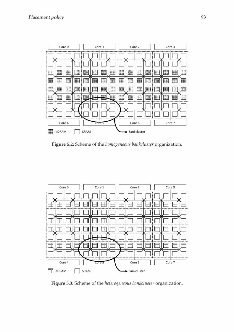
Placement policy 93
Core 0 Core 1 Core 2 Core 3
eDRAM SRAM Bankcluster
Core 4 Core 5 Core 6 Core 7
Figure 5.2: Scheme of the homogeneous bankcluster organization.
Core 0 Core 1 Core 2 Core 3
eDRAM SRAM Bankcluster
Core 4 Core 5 Core 6 Core 7
Figure 5.3: Scheme of the heterogeneous bankcluster organization.
94 Chapter 5.
in the center of the NUCA cache it neglects the effect of the migration movements to
the shared data. Note that when a data block is simultaneously accessed by two or
more cores, it is pulled to different locations by the migration scheme, so it tends to be
in the center banks [9].
Figure 5.3 shows the other organization that we propose. It combines SRAM and
eDRAM banks within a bankcluster, so we call it heterogeneous bankcluster approach.
Compared to the homogeneous bankcluster approach, this organization is not biased to
optimizing access latency to the most frequently accessed data and fairly distributes
the fast SRAM banks among the NUCA cache. However, this organization requires
SRAM and eDRAM banks to cooperate in order to emphasize the strengths of both
technologies and hide their drawbacks.
5.3.2 Placement policy for heterogeneous bankcluster
In general, when a line is requested by a core, it is stored in the cache memory in
order to exploit temporal and spatial locality found in most applications. However,
the higher the cache level, the less locality it finds. Figure 5.4 illustrates the percentage
of lines that are accessed during their lifetime in the NUCA cache. We observe
that a significant amount of data (more than 50%) that are stored in the on-chip
last-level cache memory are not accessed again during their lifetime in the NUCA
cache. It does not mean that they are not accessed at all, but the lower-level cache
satisfied these requests due to the high-locality found in the application. Based on
this observation, we define a smart placement policy for the heterogeneous bankcluster
NUCA organization that works as follows: When a data block enters into the NUCA
cache from the off-chip memory, it is located in one of the eDRAM banks (statically
predetermined based on the lower bits of its address). Then, if it is accessed again the
data block moves to the closest SRAM bank in the bankcluster.
This placement policy assures that SRAM banks store the hottest most frequently
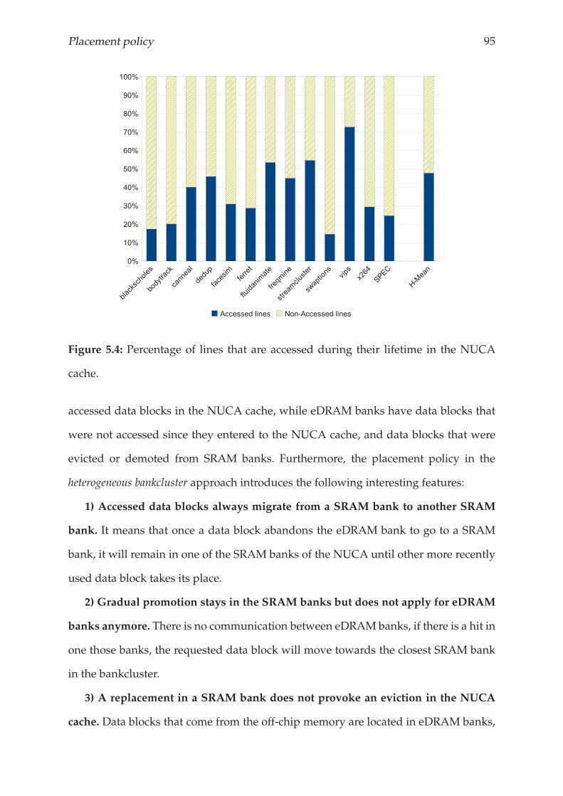
Placement policy 95
Figure 5.4: Percentage of lines that are accessed during their lifetime in the NUCA
cache.
accessed data blocks in the NUCA cache, while eDRAM banks have data blocks that
were not accessed since they entered to the NUCA cache, and data blocks that were
evicted or demoted from SRAM banks. Furthermore, the placement policy in the
heterogeneous bankcluster approach introduces the following interesting features:
1) Accessed data blocks always migrate from a SRAM bank to another SRAM
bank. It means that once a data block abandons the eDRAM bank to go to a SRAM
bank, it will remain in one of the SRAM banks of the NUCA until other more recently
used data block takes its place.
2) Gradual promotion stays in the SRAM banks but does not apply for eDRAM
banks anymore. There is no communication between eDRAM banks, if there is a hit in
one those banks, the requested data block will move towards the closest SRAM bank
in the bankcluster.
3) A replacement in a SRAM bank does not provoke an eviction in the NUCA
cache. Data blocks that come from the off-chip memory are located in eDRAM banks,
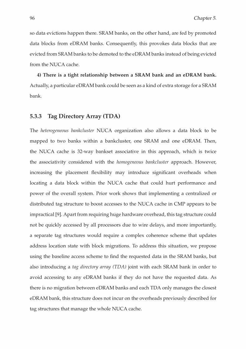
96 Chapter 5.
so data evictions happen there. SRAM banks, on the other hand, are fed by promoted
data blocks from eDRAM banks. Consequently, this provokes data blocks that are
evicted from SRAMbanks to be demoted to the eDRAMbanks instead of being evicted
from the NUCA cache.
4) There is a tight relationship between a SRAM bank and an eDRAM bank.
Actually, a particular eDRAMbank could be seen as a kind of extra storage for a SRAM
bank.
5.3.3 Tag Directory Array (TDA)
The heterogeneous bankcluster NUCA organization also allows a data block to be
mapped to two banks within a bankcluster, one SRAM and one eDRAM. Then,
the NUCA cache is 32-way bankset associative in this approach, which is twice
the associativity considered with the homogeneous bankcluster approach. However,
increasing the placement flexibility may introduce significant overheads when
locating a data block within the NUCA cache that could hurt performance and
power of the overall system. Prior work shows that implementing a centralized or
distributed tag structure to boost accesses to the NUCA cache in CMP appears to be
impractical [9]. Apart from requiring huge hardware overhead, this tag structure could
not be quickly accessed by all processors due to wire delays, and more importantly,
a separate tag structures would require a complex coherence scheme that updates
address location state with block migrations. To address this situation, we propose
using the baseline access scheme to find the requested data in the SRAM banks, but
also introducing a tag directory array (TDA) joint with each SRAM bank in order to
avoid accessing to any eDRAM banks if they do not have the requested data. As
there is no migration between eDRAM banks and each TDA only manages the closest
eDRAM bank, this structure does not incur on the overheads previously described for
tag structures that manage the whole NUCA cache.
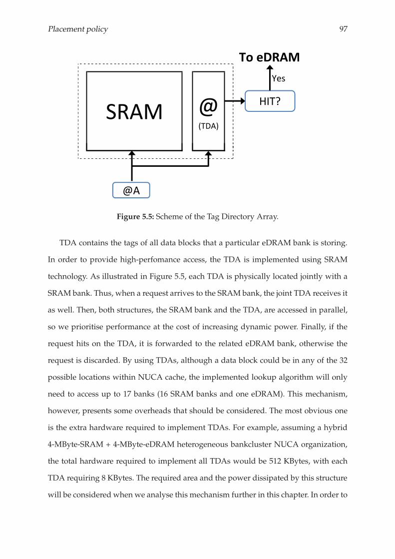
Placement policy 97
SRAM @(TDA)
HIT?
Yes
To eDRAM
@A
Figure 5.5: Scheme of the Tag Directory Array.
TDA contains the tags of all data blocks that a particular eDRAM bank is storing.
In order to provide high-perfomance access, the TDA is implemented using SRAM
technology. As illustrated in Figure 5.5, each TDA is physically located jointly with a
SRAM bank. Thus, when a request arrives to the SRAM bank, the joint TDA receives it
as well. Then, both structures, the SRAM bank and the TDA, are accessed in parallel,
so we prioritise performance at the cost of increasing dynamic power. Finally, if the
request hits on the TDA, it is forwarded to the related eDRAM bank, otherwise the
request is discarded. By using TDAs, although a data block could be in any of the 32
possible locations within NUCA cache, the implemented lookup algorithm will only
need to access up to 17 banks (16 SRAM banks and one eDRAM). This mechanism,
however, presents some overheads that should be considered. The most obvious one
is the extra hardware required to implement TDAs. For example, assuming a hybrid
4-MByte-SRAM + 4-MByte-eDRAM heterogeneous bankcluster NUCA organization,
the total hardware required to implement all TDAs would be 512 KBytes, with each
TDA requiring 8 KBytes. The required area and the power dissipated by this structure
will be considered when we analyse this mechanism further in this chapter. In order to
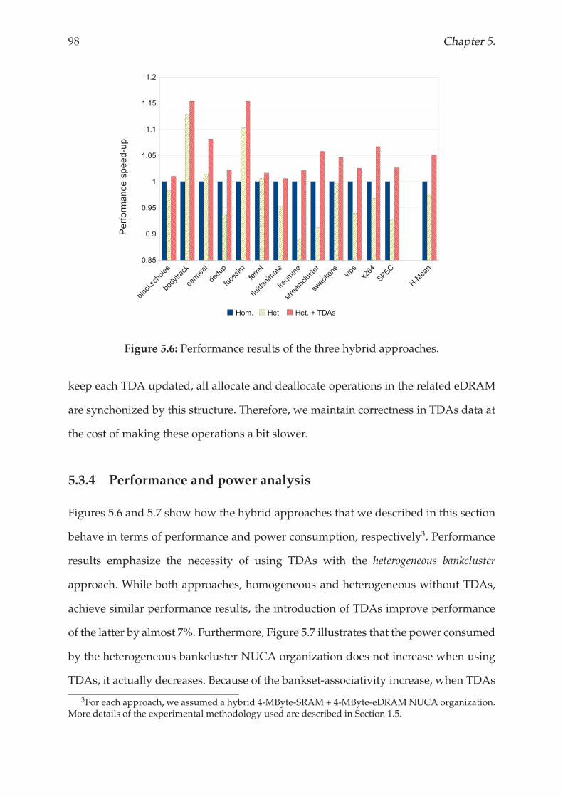
98 Chapter 5.
Figure 5.6: Performance results of the three hybrid approaches.
keep each TDA updated, all allocate and deallocate operations in the related eDRAM
are synchonized by this structure. Therefore, we maintain correctness in TDAs data at
the cost of making these operations a bit slower.
5.3.4 Performance and power analysis
Figures 5.6 and 5.7 show how the hybrid approaches that we described in this section
behave in terms of performance and power consumption, respectively3. Performance
results emphasize the necessity of using TDAs with the heterogeneous bankcluster
approach. While both approaches, homogeneous and heterogeneous without TDAs,
achieve similar performance results, the introduction of TDAs improve performance
of the latter by almost 7%. Furthermore, Figure 5.7 illustrates that the power consumed
by the heterogeneous bankcluster NUCA organization does not increase when using
TDAs, it actually decreases. Because of the bankset-associativity increase, when TDAs
3For each approach, we assumed a hybrid 4-MByte-SRAM+ 4-MByte-eDRAMNUCA organization.More details of the experimental methodology used are described in Section 1.5.
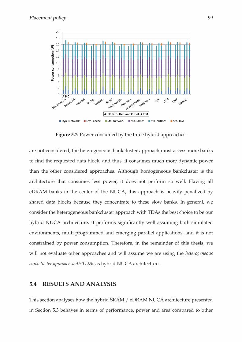
Placement policy 99
8
10
12
14
16
18
20
consumption(W
)
0
2
4
6
Power
A: Hom. B: Het. and C: Het. + TDA
Dyn. Network Dyn. Cache Sta. Network Sta. SRAM Sta. eDRAM Sta. TDA
A B C
Figure 5.7: Power consumed by the three hybrid approaches.
are not considered, the heterogeneous bankcluster approach must access more banks
to find the requested data block, and thus, it consumes much more dynamic power
than the other considered approaches. Although homogeneous bankcluster is the
architecture that consumes less power, it does not perform so well. Having all
eDRAM banks in the center of the NUCA, this approach is heavily penalized by
shared data blocks because they concentrate to these slow banks. In general, we
consider the heterogeneous bankcluster approach with TDAs the best choice to be our
hybrid NUCA architecture. It performs significantly well assuming both simulated
environments, multi-programmed and emerging parallel applications, and it is not
constrained by power consumption. Therefore, in the remainder of this thesis, we
will not evaluate other approaches and will assume we are using the heterogeneous
bankcluster approach with TDAs as hybrid NUCA architecture.
5.4 RESULTS AND ANALYSIS
This section analyses how the hybrid SRAM / eDRAMNUCA architecture presented
in Section 5.3 behaves in terms of performance, power and area compared to other
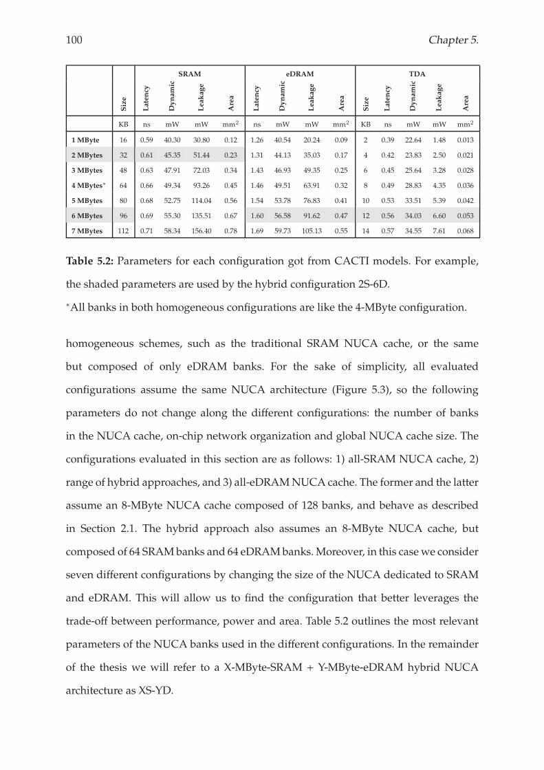
100 Chapter 5.
SRAM eDRAM TDA
Size
Latency
Dynamic
Leakage
Area
Latency
Dynamic
Leakage
Area
Size
Latency
Dynamic
Leakage
Area
KB ns mW mW mm2 ns mW mW mm2 KB ns mW mW mm2
1 MByte 16 0.59 40.30 30.80 0.12 1.26 40.54 20.24 0.09 2 0.39 22.64 1.48 0.013
2 MBytes 32 0.61 45.35 51.44 0.23 1.31 44.13 35.03 0.17 4 0.42 23.83 2.50 0.021
3 MBytes 48 0.63 47.91 72.03 0.34 1.43 46.93 49.35 0.25 6 0.45 25.64 3.28 0.028
4 MBytes∗ 64 0.66 49.34 93.26 0.45 1.46 49.51 63.91 0.32 8 0.49 28.83 4.35 0.036
5 MBytes 80 0.68 52.75 114.04 0.56 1.54 53.78 76.83 0.41 10 0.53 33.51 5.39 0.042
6 MBytes 96 0.69 55.30 135.51 0.67 1.60 56.58 91.62 0.47 12 0.56 34.03 6.60 0.053
7 MBytes 112 0.71 58.34 156.40 0.78 1.69 59.73 105.13 0.55 14 0.57 34.55 7.61 0.068
Table 5.2: Parameters for each configuration got from CACTI models. For example,
the shaded parameters are used by the hybrid configuration 2S-6D.
∗All banks in both homogeneous configurations are like the 4-MByte configuration.
homogeneous schemes, such as the traditional SRAM NUCA cache, or the same
but composed of only eDRAM banks. For the sake of simplicity, all evaluated
configurations assume the same NUCA architecture (Figure 5.3), so the following
parameters do not change along the different configurations: the number of banks
in the NUCA cache, on-chip network organization and global NUCA cache size. The
configurations evaluated in this section are as follows: 1) all-SRAM NUCA cache, 2)
range of hybrid approaches, and 3) all-eDRAMNUCA cache. The former and the latter
assume an 8-MByte NUCA cache composed of 128 banks, and behave as described
in Section 2.1. The hybrid approach also assumes an 8-MByte NUCA cache, but
composed of 64 SRAMbanks and 64 eDRAMbanks.Moreover, in this casewe consider
seven different configurations by changing the size of the NUCA dedicated to SRAM
and eDRAM. This will allow us to find the configuration that better leverages the
trade-off between performance, power and area. Table 5.2 outlines the most relevant
parameters of the NUCA banks used in the different configurations. In the remainder
of the thesis we will refer to a X-MByte-SRAM + Y-MByte-eDRAM hybrid NUCA
architecture as XS-YD.
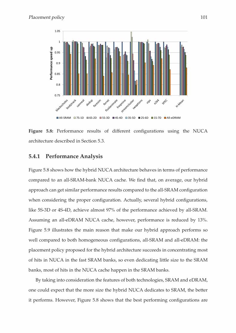
Placement policy 101
0.9
0.95
1
1.05
mance
speedup
0.75
0.8
0.85
Perform
All SRAM 7S 1D 6S 2D 5S 3D 4S 4D 3S 5D 2S 6D 1S 7D All eDRAM
Figure 5.8: Performance results of different configurations using the NUCA
architecture described in Section 5.3.
5.4.1 Performance Analysis
Figure 5.8 shows how the hybrid NUCA architecture behaves in terms of performance
compared to an all-SRAM-bank NUCA cache. We find that, on average, our hybrid
approach can get similar performance results compared to the all-SRAM configuration
when considering the proper configuration. Actually, several hybrid configurations,
like 5S-3D or 4S-4D, achieve almost 97% of the performance achieved by all-SRAM.
Assuming an all-eDRAM NUCA cache, however, performance is reduced by 13%.
Figure 5.9 illustrates the main reason that make our hybrid approach performs so
well compared to both homogeneous configurations, all-SRAM and all-eDRAM: the
placement policy proposed for the hybrid architecture succeeds in concentrating most
of hits in NUCA in the fast SRAM banks, so even dedicating little size to the SRAM
banks, most of hits in the NUCA cache happen in the SRAM banks.
By taking into consideration the features of both technologies, SRAM and eDRAM,
one could expect that the more size the hybrid NUCA dedicates to SRAM, the better
it performs. However, Figure 5.8 shows that the best performing configurations are
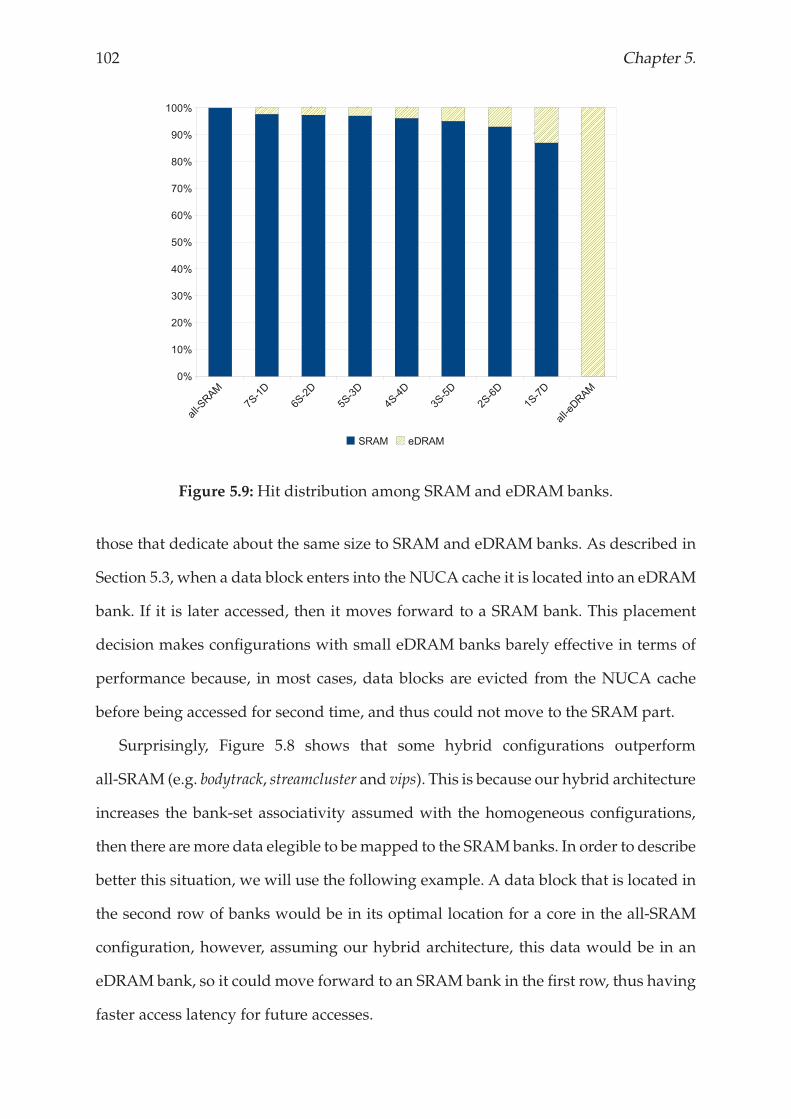
102 Chapter 5.
Figure 5.9:Hit distribution among SRAM and eDRAM banks.
those that dedicate about the same size to SRAM and eDRAM banks. As described in
Section 5.3, when a data block enters into the NUCA cache it is located into an eDRAM
bank. If it is later accessed, then it moves forward to a SRAM bank. This placement
decision makes configurations with small eDRAM banks barely effective in terms of
performance because, in most cases, data blocks are evicted from the NUCA cache
before being accessed for second time, and thus could not move to the SRAM part.
Surprisingly, Figure 5.8 shows that some hybrid configurations outperform
all-SRAM (e.g. bodytrack, streamcluster and vips). This is because our hybrid architecture
increases the bank-set associativity assumed with the homogeneous configurations,
then there aremore data elegible to bemapped to the SRAMbanks. In order to describe
better this situation, we will use the following example. A data block that is located in
the second row of banks would be in its optimal location for a core in the all-SRAM
configuration, however, assuming our hybrid architecture, this data would be in an
eDRAM bank, so it could move forward to an SRAM bank in the first row, thus having
faster access latency for future accesses.
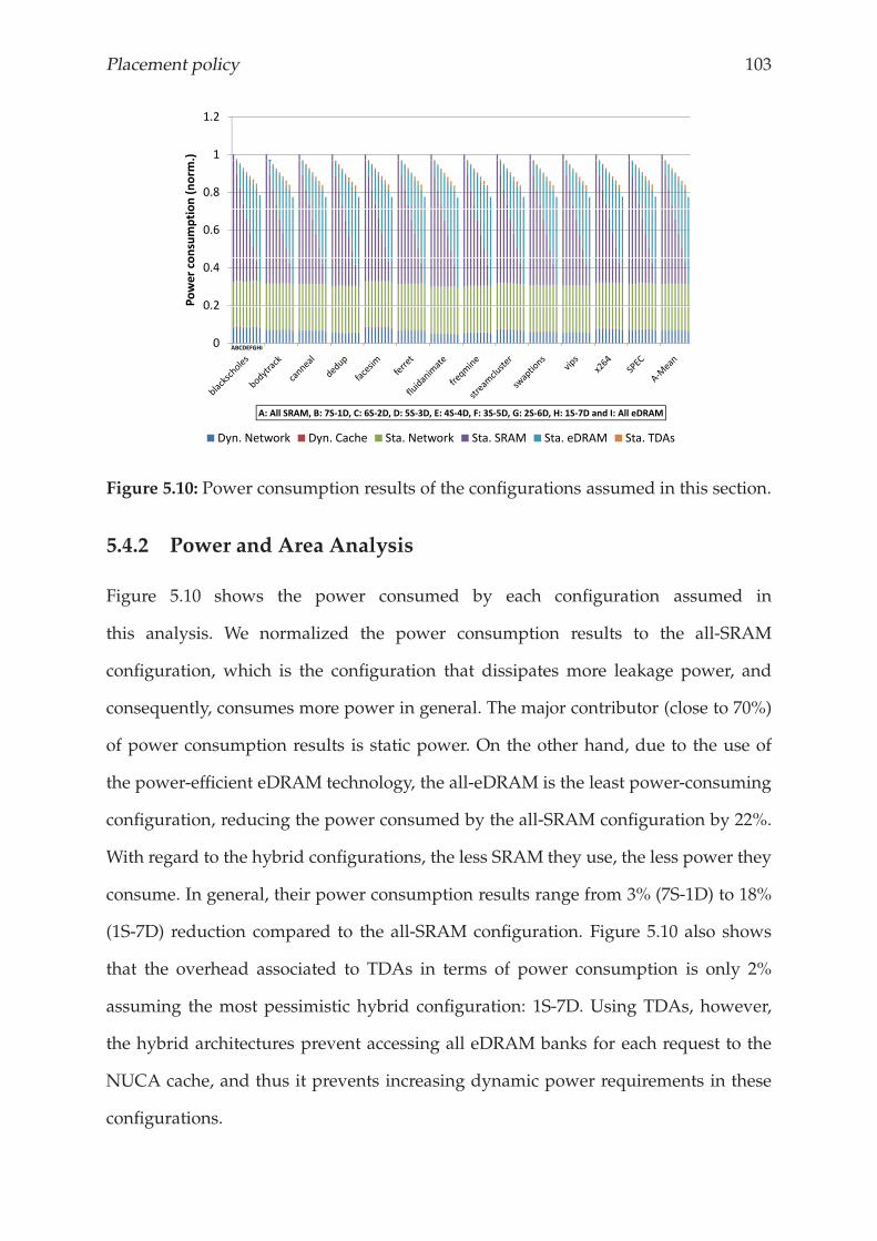
Placement policy 103
1
1.2
.)0.8
on(norm
0.6
onsumptio
0 2
0.4
Powerco
0
0.2
ABCDEFGHI
A: All SRAM, B: 7S 1D, C: 6S 2D, D: 5S 3D, E: 4S 4D, F: 3S 5D, G: 2S 6D, H: 1S 7D and I: All eDRAM
Dyn. Network Dyn. Cache Sta. Network Sta. SRAM Sta. eDRAM Sta. TDAs
Figure 5.10: Power consumption results of the configurations assumed in this section.
5.4.2 Power and Area Analysis
Figure 5.10 shows the power consumed by each configuration assumed in
this analysis. We normalized the power consumption results to the all-SRAM
configuration, which is the configuration that dissipates more leakage power, and
consequently, consumes more power in general. The major contributor (close to 70%)
of power consumption results is static power. On the other hand, due to the use of
the power-efficient eDRAM technology, the all-eDRAM is the least power-consuming
configuration, reducing the power consumed by the all-SRAM configuration by 22%.
With regard to the hybrid configurations, the less SRAM they use, the less power they
consume. In general, their power consumption results range from 3% (7S-1D) to 18%
(1S-7D) reduction compared to the all-SRAM configuration. Figure 5.10 also shows
that the overhead associated to TDAs in terms of power consumption is only 2%
assuming the most pessimistic hybrid configuration: 1S-7D. Using TDAs, however,
the hybrid architectures prevent accessing all eDRAM banks for each request to the
NUCA cache, and thus it prevents increasing dynamic power requirements in these
configurations.
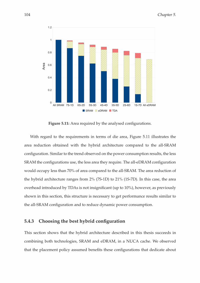
104 Chapter 5.
Figure 5.11: Area required by the analysed configurations.
With regard to the requirements in terms of die area, Figure 5.11 illustrates the
area reduction obtained with the hybrid architecture compared to the all-SRAM
configuration. Similar to the trend observed on the power consumption results, the less
SRAM the configurations use, the less area they require. The all-eDRAM configuration
would occupy less than 70% of area compared to the all-SRAM. The area reduction of
the hybrid architecture ranges from 2% (7S-1D) to 21% (1S-7D). In this case, the area
overhead introduced by TDAs is not insignificant (up to 10%), however, as previously
shown in this section, this structure is necessary to get performance results similar to
the all-SRAM configuration and to reduce dynamic power consumption.
5.4.3 Choosing the best hybrid configuration
This section shows that the hybrid architecture described in this thesis succeeds in
combining both technologies, SRAM and eDRAM, in a NUCA cache. We observed
that the placement policy assumed benefits these configurations that dedicate about
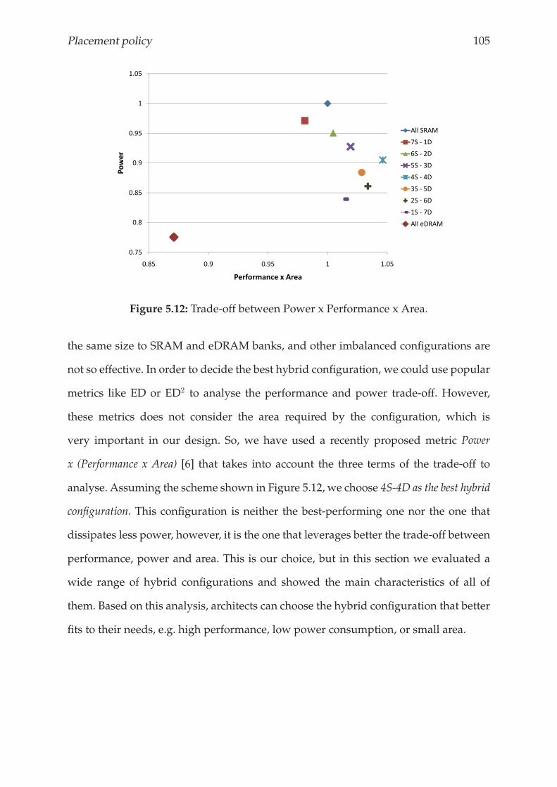
Placement policy 105
1.05
0 95
1
All SRAM
0 9
0.95
wer
All SRAM
7S 1D
6S 2D
0 85
0.9
Pow 5S 3D
4S 4D
3S 5D
0.8
0.852S 6D
1S 7D
All eDRAM
0.75
0.8 All eDRAM
0.85 0.9 0.95 1 1.05
Performance x Area
Figure 5.12: Trade-off between Power x Performance x Area.
the same size to SRAM and eDRAM banks, and other imbalanced configurations are
not so effective. In order to decide the best hybrid configuration, we could use popular
metrics like ED or ED2 to analyse the performance and power trade-off. However,
these metrics does not consider the area required by the configuration, which is
very important in our design. So, we have used a recently proposed metric Power
x (Performance x Area) [6] that takes into account the three terms of the trade-off to
analyse. Assuming the scheme shown in Figure 5.12, we choose 4S-4D as the best hybrid
configuration. This configuration is neither the best-performing one nor the one that
dissipates less power, however, it is the one that leverages better the trade-off between
performance, power and area. This is our choice, but in this section we evaluated a
wide range of hybrid configurations and showed the main characteristics of all of
them. Based on this analysis, architects can choose the hybrid configuration that better
fits to their needs, e.g. high performance, low power consumption, or small area.
106 Chapter 5.
5.5 EXPLOITING ARCHITECTURAL BENEFITS
Section 5.4 shows that a well-balanced configuration of the proposed hybrid NUCA
architecture achieves similar performance results to an architecture composed of
only SRAM banks, but occupies about 15% less area and dissipates 10% less power.
Architects could manage this significant area reduction to either implement smaller
and more power-efficient designs, or re-design architectural structures to improve
overall performance. For example, the most recent architecture from Intel®, Nehalem,
assigns more than 50% of the chip area to the last-level cache memory, thus the area
reduced of using the proposed hybrid architecture as last-level cache in this processor
would be enough to integrate an extra core.
In this section, we evaluate two different scenarios assuming that the remaining
transistors are used to increase the last-level cache memory size. Thus, assuming
the best hybrid configuration, we increase either the size designated to SRAM banks,
or to eDRAM banks. The 15% area reduction allows for integrating up to 1 MByte
extra to the SRAM banks, resulting a 5-MByte-SRAM + 4-MByte-eDRAM hybrid
configuration. On the other hand, assuming eDRAM’s higher density, architects could
manage to re-design the 4S-4D configuration by dedicating up to 6 MBytes to the
eDRAM banks. Both configurations, 5S-4D and 4S-6D, occupy almost the same area
as a NUCA architecture composed of only SRAM banks.
Figure 5.13 illustrates how the extended configurations, 5S-4D and 4S-6D, behave
in terms of performance compared to the all-SRAM. On average, both configurations
outperform the all-SRAM configuration by 4%, and 4S-4D by 10%. However, we
observe that the performance benefits are much higher with memory-intensive
parallel applications, like streamcluster and canneal, and with the multi-programmed
scenario (mix of SPEC CPU2006 applications). Figure 5.13 also shows that most of
workloads achieve higher performance results with the configuration that provide the
largest cache memory (4S-6D), instead of with the one that provides more capacity on
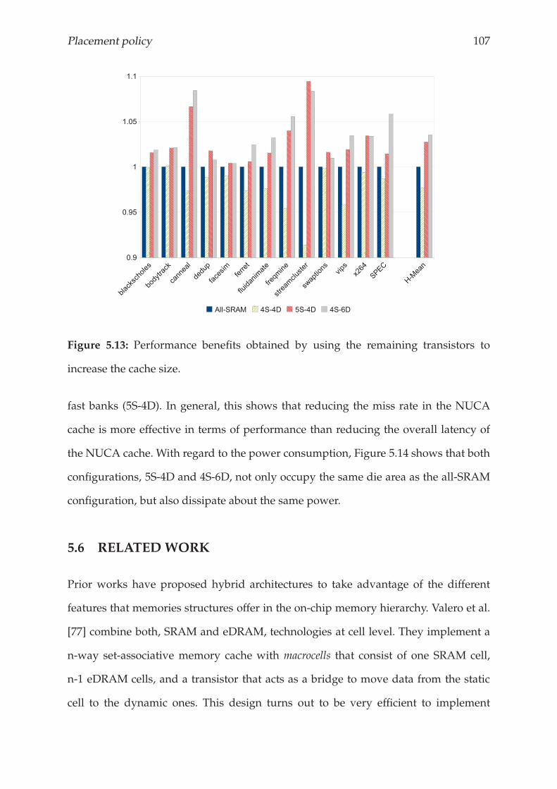
Placement policy 107
Figure 5.13: Performance benefits obtained by using the remaining transistors to
increase the cache size.
fast banks (5S-4D). In general, this shows that reducing the miss rate in the NUCA
cache is more effective in terms of performance than reducing the overall latency of
the NUCA cache. With regard to the power consumption, Figure 5.14 shows that both
configurations, 5S-4D and 4S-6D, not only occupy the same die area as the all-SRAM
configuration, but also dissipate about the same power.
5.6 RELATED WORK
Prior works have proposed hybrid architectures to take advantage of the different
features that memories structures offer in the on-chip memory hierarchy. Valero et al.
[77] combine both, SRAM and eDRAM, technologies at cell level. They implement a
n-way set-associative memory cache with macrocells that consist of one SRAM cell,
n-1 eDRAM cells, and a transistor that acts as a bridge to move data from the static
cell to the dynamic ones. This design turns out to be very efficient to implement
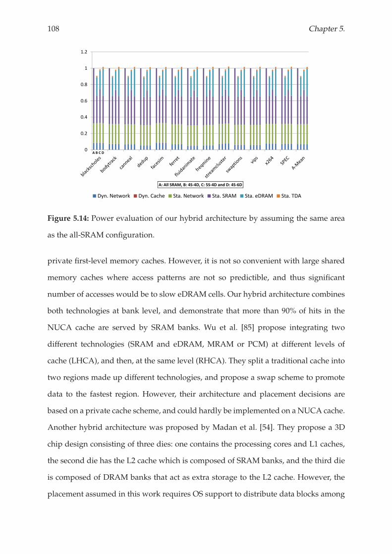
108 Chapter 5.
0 4
0.6
0.8
1
1.2
0
0.2
0.4
A: All SRAM, B: 4S 4D, C: 5S 4D and D: 4S 6D
Dyn. Network Dyn. Cache Sta. Network Sta. SRAM Sta. eDRAM Sta. TDA
A B C D
Figure 5.14: Power evaluation of our hybrid architecture by assuming the same area
as the all-SRAM configuration.
private first-level memory caches. However, it is not so convenient with large shared
memory caches where access patterns are not so predictible, and thus significant
number of accesses would be to slow eDRAM cells. Our hybrid architecture combines
both technologies at bank level, and demonstrate that more than 90% of hits in the
NUCA cache are served by SRAM banks. Wu et al. [85] propose integrating two
different technologies (SRAM and eDRAM, MRAM or PCM) at different levels of
cache (LHCA), and then, at the same level (RHCA). They split a traditional cache into
two regions made up different technologies, and propose a swap scheme to promote
data to the fastest region. However, their architecture and placement decisions are
based on a private cache scheme, and could hardly be implemented on aNUCA cache.
Another hybrid architecture was proposed by Madan et al. [54]. They propose a 3D
chip design consisting of three dies: one contains the processing cores and L1 caches,
the second die has the L2 cache which is composed of SRAM banks, and the third die
is composed of DRAM banks that act as extra storage to the L2 cache. However, the
placement assumed in this work requires OS support to distribute data blocks among
Placement policy 109
the caches, and consequently to find them in the L2 cache.
SRAM and MRAM are also combined to create a L2 hybrid cache in a CMP [74].
This combination tries to solve the problems, in terms of long write latency and high
write energy, which MRAM introduces in isolation. Another combination of memory
technologies has been recently proposed to be included in main memory [70, 69]. In
this hybrid approach, PCM and DRAM are combined in two levels (first level DRAM
and second level PCM) to solve the write endurance problems of the PCM memory
and taking profit of its 4x density compared to DRAM.
5.7 CONCLUSIONS
IBM® have already succeeded in integrating eDRAM technology in the on-chip
memory cache hierarchy of their latest processor, POWER7. This could be considered
the starting point to integrate more sophisticated hybrid cache structures in the near
future. Here, we propose a hybrid cache architecture that combines both technologies
in the same cache level, and make them work cooperatively. Our architecture,
organized as a NUCA cache, uses a smart placement policy that efficiently distributes
data blocks among SRAM and eDRAM banks by emphasizing their strengths and
hiding their drawbacks. We evaluate a wide range of configurations and observe
that a well-balanced hybrid configuration achieves similar performance results to an
architecture composed of only SRAM banks, but occupies about 15% less area and
dissipates 10% less power. Finally, we have analysed different alternatives to take
advantage of the area reduction we got by using the hybrid architecture that lead us
to get performance benefits up to 10%.

110 Chapter 5.
Chapter 6
Migration policy
Existing migration techniques are effective in concentrating the most frequently accessed data
in the NUCA banks with the smallest access latency. However, a significant percentage of hits
in the NUCA cache are still resolved in slower banks. To address this situation, in this chapter,
we propose the Migration Prefetcher. This is a migration technique that moves data to the
optimal banks in advance of being required.

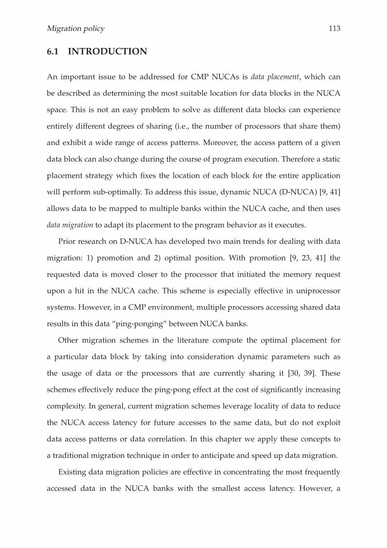
Migration policy 113
6.1 INTRODUCTION
An important issue to be addressed for CMP NUCAs is data placement, which can
be described as determining the most suitable location for data blocks in the NUCA
space. This is not an easy problem to solve as different data blocks can experience
entirely different degrees of sharing (i.e., the number of processors that share them)
and exhibit a wide range of access patterns. Moreover, the access pattern of a given
data block can also change during the course of program execution. Therefore a static
placement strategy which fixes the location of each block for the entire application
will perform sub-optimally. To address this issue, dynamic NUCA (D-NUCA) [9, 41]
allows data to be mapped to multiple banks within the NUCA cache, and then uses
data migration to adapt its placement to the program behavior as it executes.
Prior research on D-NUCA has developed two main trends for dealing with data
migration: 1) promotion and 2) optimal position. With promotion [9, 23, 41] the
requested data is moved closer to the processor that initiated the memory request
upon a hit in the NUCA cache. This scheme is especially effective in uniprocessor
systems. However, in a CMP environment, multiple processors accessing shared data
results in this data “ping-ponging” between NUCA banks.
Other migration schemes in the literature compute the optimal placement for
a particular data block by taking into consideration dynamic parameters such as
the usage of data or the processors that are currently sharing it [30, 39]. These
schemes effectively reduce the ping-pong effect at the cost of significantly increasing
complexity. In general, current migration schemes leverage locality of data to reduce
the NUCA access latency for future accesses to the same data, but do not exploit
data access patterns or data correlation. In this chapter we apply these concepts to
a traditional migration technique in order to anticipate and speed up data migration.
Existing data migration policies are effective in concentrating the most frequently
accessed data in the NUCA banks with the smallest access latency. However, a
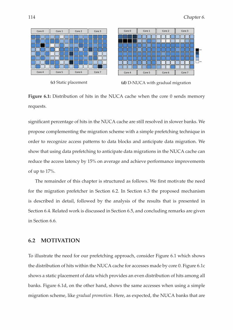
114 Chapter 6.
Core 0 Core 1 Core 2 Core 3
Core 4 Core 5 Core 6 Core 7
(c) Static placement
Core 0 Core 1 Core 2 Core 3
Core 4 Core 5 Core 6 Core 7
(d) D-NUCA with gradual migration
MAX
MIN
Figure 6.1: Distribution of hits in the NUCA cache when the core 0 sends memory
requests.
significant percentage of hits in the NUCA cache are still resolved in slower banks. We
propose complementing the migration scheme with a simple prefetching technique in
order to recognize access patterns to data blocks and anticipate data migration. We
show that using data prefetching to anticipate data migrations in the NUCA cache can
reduce the access latency by 15% on average and achieve performance improvements
of up to 17%.
The remainder of this chapter is structured as follows. We first motivate the need
for the migration prefetcher in Section 6.2. In Section 6.3 the proposed mechanism
is described in detail, followed by the analysis of the results that is presented in
Section 6.4. Relatedwork is discussed in Section 6.5, and concluding remarks are given
in Section 6.6.
6.2 MOTIVATION
To illustrate the need for our prefetching approach, consider Figure 6.1 which shows
the distribution of hits within the NUCA cache for accesses made by core 0. Figure 6.1c
shows a static placement of data which provides an even distribution of hits among all
banks. Figure 6.1d, on the other hand, shows the same accesses when using a simple
migration scheme, like gradual promotion. Here, as expected, the NUCA banks that are
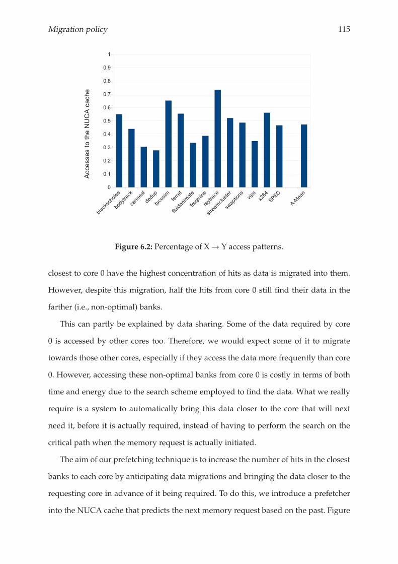
Migration policy 115
Figure 6.2: Percentage of X→ Y access patterns.
closest to core 0 have the highest concentration of hits as data is migrated into them.
However, despite this migration, half the hits from core 0 still find their data in the
farther (i.e., non-optimal) banks.
This can partly be explained by data sharing. Some of the data required by core
0 is accessed by other cores too. Therefore, we would expect some of it to migrate
towards those other cores, especially if they access the data more frequently than core
0. However, accessing these non-optimal banks from core 0 is costly in terms of both
time and energy due to the search scheme employed to find the data. What we really
require is a system to automatically bring this data closer to the core that will next
need it, before it is actually required, instead of having to perform the search on the
critical path when the memory request is actually initiated.
The aim of our prefetching technique is to increase the number of hits in the closest
banks to each core by anticipating data migrations and bringing the data closer to the
requesting core in advance of it being required. To do this, we introduce a prefetcher
into the NUCA cache that predicts the next memory request based on the past. Figure
116 Chapter 6.
6.2 shows the potential for our prefetching strategy using our benchmark applications
described in Section 2.2. Here, for each pair of consecutive memory accesses by a single
core X, Y we show the fraction of accesses to the cache for X where the next access by
the same core is to address Y. In other words, the number of times an access to X is
immediately followed by an access to Y. Figure 6.2 shows that, on average, almost
50% of the accesses exhibit this pattern and that this behavior is present across all
applications, ranging from 30% to 70% of all accesses. We exploit this result in our
prefetcher to predict the next memory address that will be required based on the
current.
6.3 THEMIGRATION PREFETCHER
This section describes our migration prefetcher in detail. The implementation and the
basic concepts of the prefetcher are described in Section 6.3.1. Then, we show several
alternatives to deal with the prefetching strategies, accuracy and the data search
scheme, which are described in Section 6.3.2, 6.3.3 and 6.3.4, respectively. Finally, the
actual prefetcher is presented in Section 6.3.5.
6.3.1 How the prefetcher works
Figure 6.3 shows the NUCA cache including the prefetcher components. There are
eight prefetchers (one per core) that are located in the cache controller, which is the
entrance point to the NUCA from the L1 cache. A prefetcher consists of the prefetcher
slot (PS), which stores the prefetched data, a structure to manage the outstanding
prefetching request and the last request sent from the L1, and the Next Address Table
(NAT), which keeps track of the data access patterns. For each address requested, the
NAT stores the next address to be accessed. In this section, for the sake of simplicity,
we assume that the NAT is unlimited table which avoids address conflicts.
The prefetcher manages memory requests to the NUCA cache and keeps track of
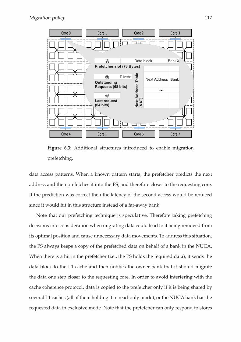
Migration policy 117
Figure 6.3: Additional structures introduced to enable migration
prefetching.
data access patterns. When a known pattern starts, the prefetcher predicts the next
address and then prefetches it into the PS, and therefore closer to the requesting core.
If the prediction was correct then the latency of the second access would be reduced
since it would hit in this structure instead of a far-away bank.
Note that our prefetching technique is speculative. Therefore taking prefetching
decisions into consideration when migrating data could lead to it being removed from
its optimal position and cause unnecessary data movements. To address this situation,
the PS always keeps a copy of the prefetched data on behalf of a bank in the NUCA.
When there is a hit in the prefetcher (i.e., the PS holds the required data), it sends the
data block to the L1 cache and then notifies the owner bank that it should migrate
the data one step closer to the requesting core. In order to avoid interfering with the
cache coherence protocol, data is copied to the prefetcher only if it is being shared by
several L1 caches (all of them holding it in read-only mode), or the NUCA bank has the
requested data in exclusive mode. Note that the prefetcher can only respond to stores
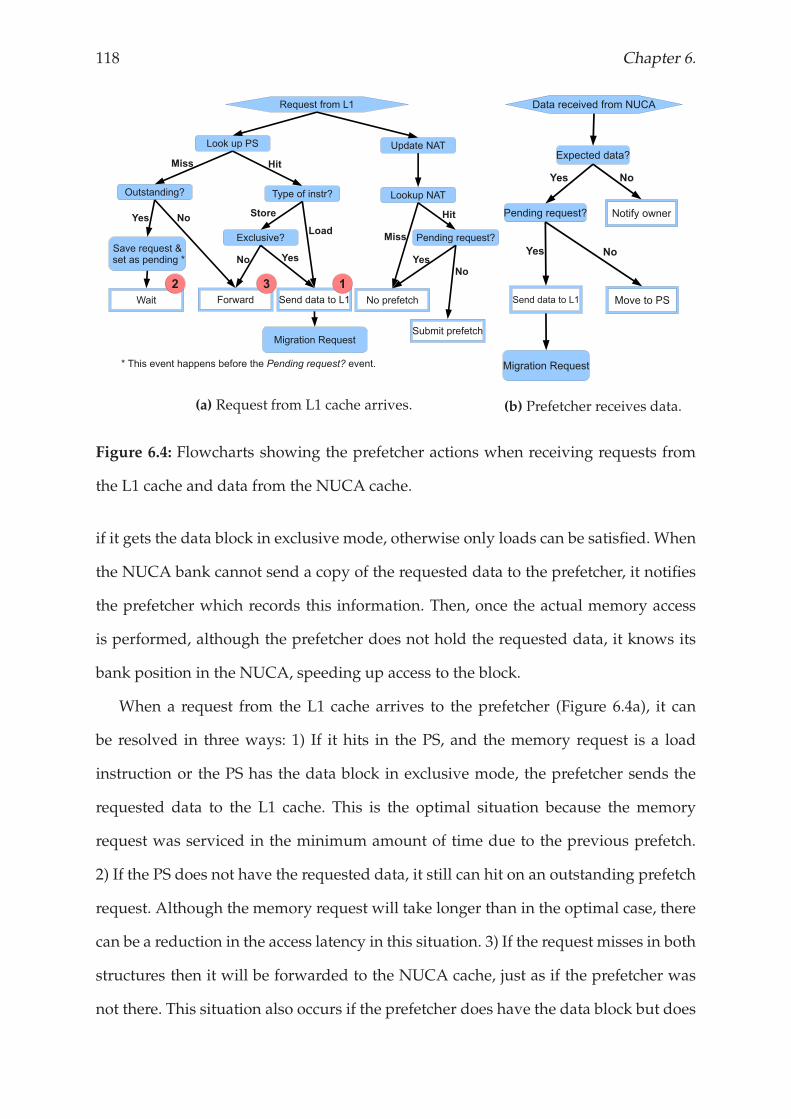
118 Chapter 6.
(a) Request from L1 cache arrives. (b) Prefetcher receives data.
Figure 6.4: Flowcharts showing the prefetcher actions when receiving requests from
the L1 cache and data from the NUCA cache.
if it gets the data block in exclusive mode, otherwise only loads can be satisfied. When
the NUCA bank cannot send a copy of the requested data to the prefetcher, it notifies
the prefetcher which records this information. Then, once the actual memory access
is performed, although the prefetcher does not hold the requested data, it knows its
bank position in the NUCA, speeding up access to the block.
When a request from the L1 cache arrives to the prefetcher (Figure 6.4a), it can
be resolved in three ways: 1) If it hits in the PS, and the memory request is a load
instruction or the PS has the data block in exclusive mode, the prefetcher sends the
requested data to the L1 cache. This is the optimal situation because the memory
request was serviced in the minimum amount of time due to the previous prefetch.
2) If the PS does not have the requested data, it still can hit on an outstanding prefetch
request. Although the memory request will take longer than in the optimal case, there
can be a reduction in the access latency in this situation. 3) If the request misses in both
structures then it will be forwarded to the NUCA cache, just as if the prefetcher was
not there. This situation also occurs if the prefetcher does have the data block but does
Migration policy 119
not satisfy the coherence requirements for it, (e.g., the PS is storing the requested data
in read-only mode and the core wants it in exclusive).
At the same time as checking the PS, the NAT is updated by storing the current
address in the entry for the last request, then updating the last request field with
the current address. If a pattern starting with the address of the current memory
request exists in the NAT then the prefetcher submits a prefetch request and updates
the outstanding request field. Note that if the prefetcher already has an outstanding
prefetch request to the same memory location as the current address, it cannot submit
a new prefetch request. Instead, the prefetcher must wait until the data comes back
from the NUCA cache.
Submitting a prefetch request does not guarantee that the prefetcher gets any data.
For example, the required data may not be in the NUCA cache. In this case, the
prefetcher is notified, leading to case 3) above. Due to this we use only one slot to
keep track of outstanding prefetch requests and this can be overwritten with a new
prefetch request if the data is not found in the cache.
Figure 6.4b illustrates the behavior of the prefetcher when it receives the prefetched
data from the NUCA cache. If the prefetch request is still alive and there is a pending
request, the prefetcher sends the received data to the L1 cache and it notifies the owner
bank to migrate the prefetched data block one-step closer to the requesting core. Note
that if the coherence requirements are not satisfied then the pending memory request
must be forwarded to the NUCA cache. On the other hand, if there is no pending
request then the received data is stored in the PS.
6.3.2 Prefetching strategies
Updating the NAT with the correct addresses is crucial for the prefetch requests to
be useful in the future. In this section we propose including a saturating counter
with each line in the NAT that shows the confidence of the corresponding prediction.

120 Chapter 6.
Figure 6.5: Fraction of prefetch requests that were useful for varying
confidence counter sizes.
When updating the NAT, we first update and check the confidence counter. If the
former address is the same as the new one the confidence counter is increased by one,
otherwise it is decreased by one. If the modified confidence counter is greater than
zero then the NAT will not be updated with the new address, instead keeping the
old address. This strategy prevents the removal of a good prediction by a single miss.
This is important, for example, when executing loops where there is a regular pattern
to memory accesses. The loop will iterate many times but, on the final iteration, the
prediction based on the last memory access will be incorrect. However, this will only
occur once and we want to maintain the old prediction for the next time the loop
is executed. Through the use of the confidence system we can ensure that the old
prediction is not unnecessarily removed.
Figure 6.5 shows the fraction of prefetch requests that ended up being useful as the
size of the confidence counter increases. This shows that implementing a confidence
counter per NAT line effectively increases the rate of useful prefetch requests by 5%
Migration policy 121
on average and up to 10% in the best case. However, we also observe that using
more than one bit to implement the confidence system does not provide benefits,
and can even reduce the performance of the system. This happens because some data
blocks eventually change behavior and are followed by a different memory access.
The greater the saturated counter, the longer the prefetcher takes to catch up with its
current behavior.
Based on this analysis, we implemented a one-bit confidence system in the
prefetcher. The prefetcher includes one extra bit per NAT line to represent the
confidence counter and a comparator to determine whether the NAT line should be
updated. We take these overheads into consideration when computing the prefetcher
latency and energy consumption.
6.3.3 Accuracy
Up to this point we have considered an unlimited NAT. However, this is not feasible
to implement, requiring 258 lines of 58 bits for a 64-bit processor with data blocks of 64
bytes. Therefore, this section analyses the accuracy loss that the prefetcher experiences
if we assume an implementable NAT. Figure 6.6 shows the percentage of prefetch
requests that are submitted using another address’s information, caused by a conflict
in theNAT.We show six configurations that use between 6 and 16 bits from the address
to directly index into the NAT. This figure shows that conflicts on the NAT increase
exponentially as the NAT’s size decreases. For a very small NAT of 64 lines (6 bits),
almost every prefetch uses the wrong information and the prefetcher is practically
useless. However, using bigger tables (12-14 bits) means that only 25% of prefetch
requests use erroneous information. The hardware overhead of using 12 bits to map
addresses to the NAT is 232 KBytes, 29 KBytes per NAT. If we use 14 bits, the total
overhead is almost 1 MByte.
A smarter implementation to reduce the hardware required to implement the
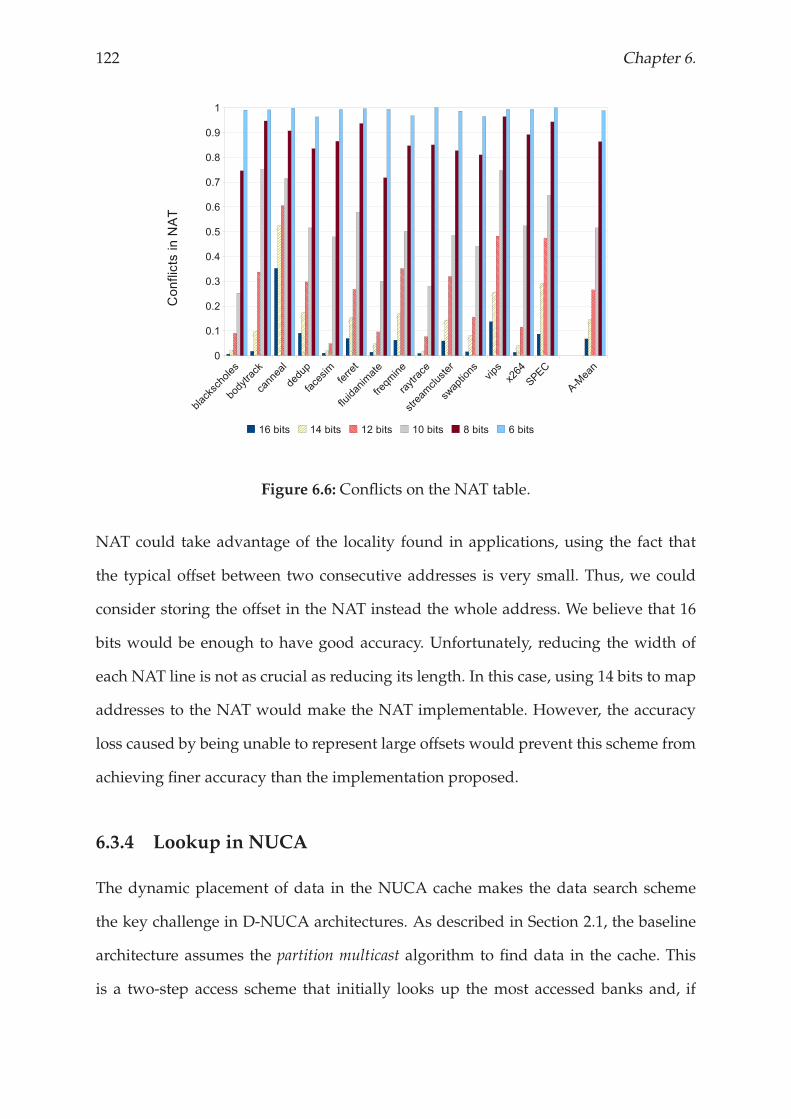
122 Chapter 6.
Figure 6.6: Conflicts on the NAT table.
NAT could take advantage of the locality found in applications, using the fact that
the typical offset between two consecutive addresses is very small. Thus, we could
consider storing the offset in the NAT instead the whole address. We believe that 16
bits would be enough to have good accuracy. Unfortunately, reducing the width of
each NAT line is not as crucial as reducing its length. In this case, using 14 bits to map
addresses to the NAT would make the NAT implementable. However, the accuracy
loss caused by being unable to represent large offsets would prevent this scheme from
achieving finer accuracy than the implementation proposed.
6.3.4 Lookup in NUCA
The dynamic placement of data in the NUCA cache makes the data search scheme
the key challenge in D-NUCA architectures. As described in Section 2.1, the baseline
architecture assumes the partition multicast algorithm to find data in the cache. This
is a two-step access scheme that initially looks up the most accessed banks and, if
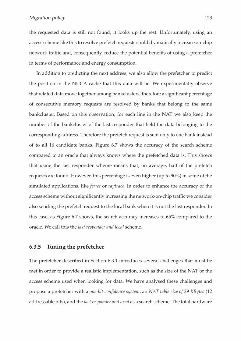
Migration policy 123
the requested data is still not found, it looks up the rest. Unfortunately, using an
access scheme like this to resolve prefetch requests could dramatically increase on-chip
network traffic and, consequently, reduce the potential benefits of using a prefetcher
in terms of performance and energy consumption.
In addition to predicting the next address, we also allow the prefetcher to predict
the position in the NUCA cache that this data will be. We experimentally observe
that related data move together among bankclusters, therefore a significant percentage
of consecutive memory requests are resolved by banks that belong to the same
bankcluster. Based on this observation, for each line in the NAT we also keep the
number of the bankcluster of the last responder that held the data belonging to the
corresponding address. Therefore the prefetch request is sent only to one bank instead
of to all 16 candidate banks. Figure 6.7 shows the accuracy of the search scheme
compared to an oracle that always knows where the prefetched data is. This shows
that using the last responder scheme means that, on average, half of the prefetch
requests are found. However, this percentage is even higher (up to 90%) in some of the
simulated applications, like ferret or raytrace. In order to enhance the accuracy of the
access schemewithout significantly increasing the network-on-chip traffic we consider
also sending the prefetch request to the local bank when it is not the last responder. In
this case, as Figure 6.7 shows, the search accuracy increases to 65% compared to the
oracle. We call this the last responder and local scheme.
6.3.5 Tuning the prefetcher
The prefetcher described in Section 6.3.1 introduces several challenges that must be
met in order to provide a realistic implementation, such as the size of the NAT or the
access scheme used when looking for data. We have analysed these challenges and
propose a prefetcher with a one-bit confidence system, an NAT table size of 29 KBytes (12
addressable bits), and the last responder and local as a search scheme. The total hardware
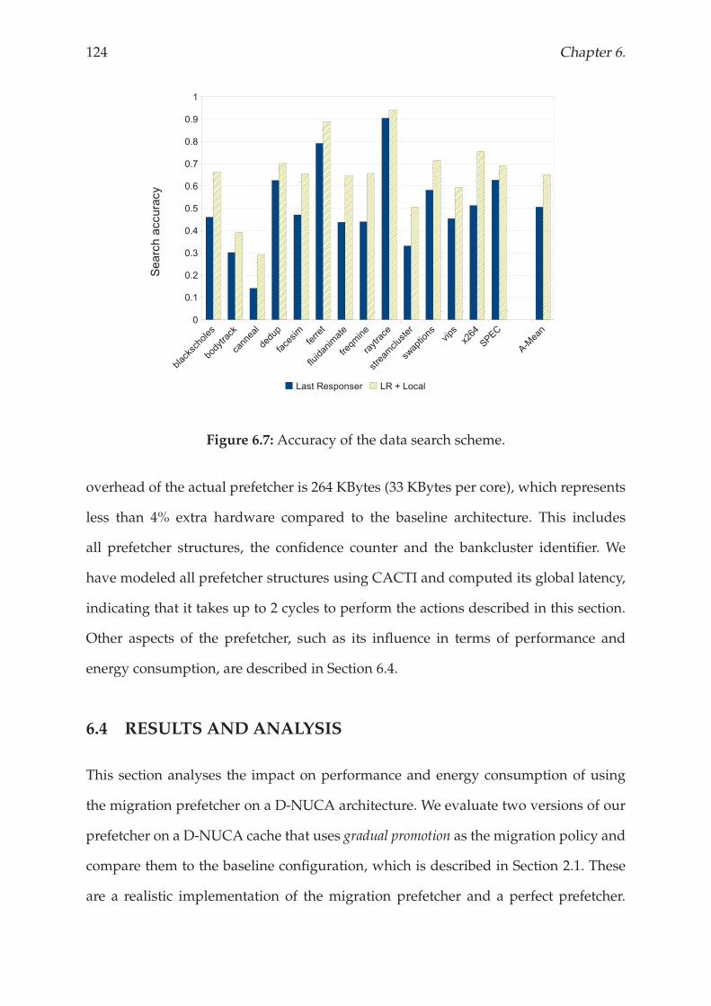
124 Chapter 6.
Figure 6.7: Accuracy of the data search scheme.
overhead of the actual prefetcher is 264 KBytes (33 KBytes per core), which represents
less than 4% extra hardware compared to the baseline architecture. This includes
all prefetcher structures, the confidence counter and the bankcluster identifier. We
have modeled all prefetcher structures using CACTI and computed its global latency,
indicating that it takes up to 2 cycles to perform the actions described in this section.
Other aspects of the prefetcher, such as its influence in terms of performance and
energy consumption, are described in Section 6.4.
6.4 RESULTS AND ANALYSIS
This section analyses the impact on performance and energy consumption of using
the migration prefetcher on a D-NUCA architecture. We evaluate two versions of our
prefetcher on a D-NUCA cache that uses gradual promotion as the migration policy and
compare them to the baseline configuration, which is described in Section 2.1. These
are a realistic implementation of the migration prefetcher and a perfect prefetcher.
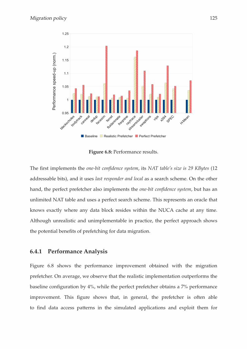
Migration policy 125
Figure 6.8: Performance results.
The first implements the one-bit confidence system, its NAT table’s size is 29 KBytes (12
addressable bits), and it uses last responder and local as a search scheme. On the other
hand, the perfect prefetcher also implements the one-bit confidence system, but has an
unlimited NAT table and uses a perfect search scheme. This represents an oracle that
knows exactly where any data block resides within the NUCA cache at any time.
Although unrealistic and unimplementable in practice, the perfect approach shows
the potential benefits of prefetching for data migration.
6.4.1 Performance Analysis
Figure 6.8 shows the performance improvement obtained with the migration
prefetcher. On average, we observe that the realistic implementation outperforms the
baseline configuration by 4%, while the perfect prefetcher obtains a 7% performance
improvement. This figure shows that, in general, the prefetcher is often able
to find data access patterns in the simulated applications and exploit them for
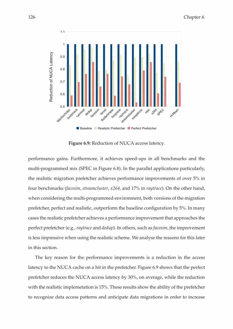
126 Chapter 6.
Figure 6.9: Reduction of NUCA access latency.
performance gains. Furthermore, it achieves speed-ups in all benchmarks and the
multi-programmed mix (SPEC in Figure 6.8). In the parallel applications particularly,
the realistic migration prefetcher achieves performance improvements of over 5% in
four benchmarks (facesim, streamcluster, x264, and 17% in raytrace). On the other hand,
when considering themulti-programmed environment, both versions of themigration
prefetcher, perfect and realistic, outperform the baseline configuration by 5%. In many
cases the realistic prefetcher achieves a performance improvement that approaches the
perfect prefetcher (e.g., raytrace and dedup). In others, such as facesim, the improvement
is less impressive when using the realistic scheme.We analyse the reasons for this later
in this section.
The key reason for the performance improvements is a reduction in the access
latency to the NUCA cache on a hit in the prefetcher. Figure 6.9 shows that the perfect
prefetcher reduces the NUCA access latency by 30%, on average, while the reduction
with the realistic implemetation is 15%. These results show the ability of the prefetcher
to recognize data access patterns and anticipate data migrations in order to increase
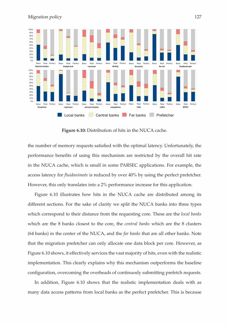
Migration policy 127
Figure 6.10: Distribution of hits in the NUCA cache.
the number of memory requests satisfied with the optimal latency. Unfortunately, the
performance benefits of using this mechanism are restricted by the overall hit rate
in the NUCA cache, which is small in some PARSEC applications. For example, the
access latency for fluidanimate is reduced by over 40% by using the perfect prefetcher.
However, this only translates into a 2% performance increase for this application.
Figure 6.10 illustrates how hits in the NUCA cache are distributed among its
different sections. For the sake of clarity we split the NUCA banks into three types
which correspond to their distance from the requesting core. These are the local banks
which are the 8 banks closest to the core, the central banks which are the 8 clusters
(64 banks) in the center of the NUCA, and the far banks that are all other banks. Note
that the migration prefetcher can only allocate one data block per core. However, as
Figure 6.10 shows, it effectively services the vast majority of hits, evenwith the realistic
implementation. This clearly explains why this mechanism outperforms the baseline
configuration, overcoming the overheads of continuosly submitting prefetch requests.
In addition, Figure 6.10 shows that the realistic implementation deals with as
many data access patterns from local banks as the perfect prefetcher. This is because
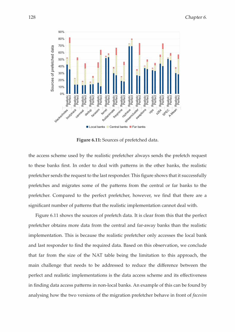
128 Chapter 6.
Figure 6.11: Sources of prefetched data.
the access scheme used by the realistic prefetcher always sends the prefetch request
to these banks first. In order to deal with patterns in the other banks, the realistic
prefetcher sends the request to the last responder. This figure shows that it successfully
prefetches and migrates some of the patterns from the central or far banks to the
prefetcher. Compared to the perfect prefetcher, however, we find that there are a
significant number of patterns that the realistic implementation cannot deal with.
Figure 6.11 shows the sources of prefetch data. It is clear from this that the perfect
prefetcher obtains more data from the central and far-away banks than the realistic
implementation. This is because the realistic prefetcher only accesses the local bank
and last responder to find the required data. Based on this observation, we conclude
that far from the size of the NAT table being the limitation to this approach, the
main challenge that needs to be addressed to reduce the difference between the
perfect and realistic implementations is the data access scheme and its effectiveness
in finding data access patterns in non-local banks. An example of this can be found by
analysing how the two versions of the migration prefetcher behave in front of facesim
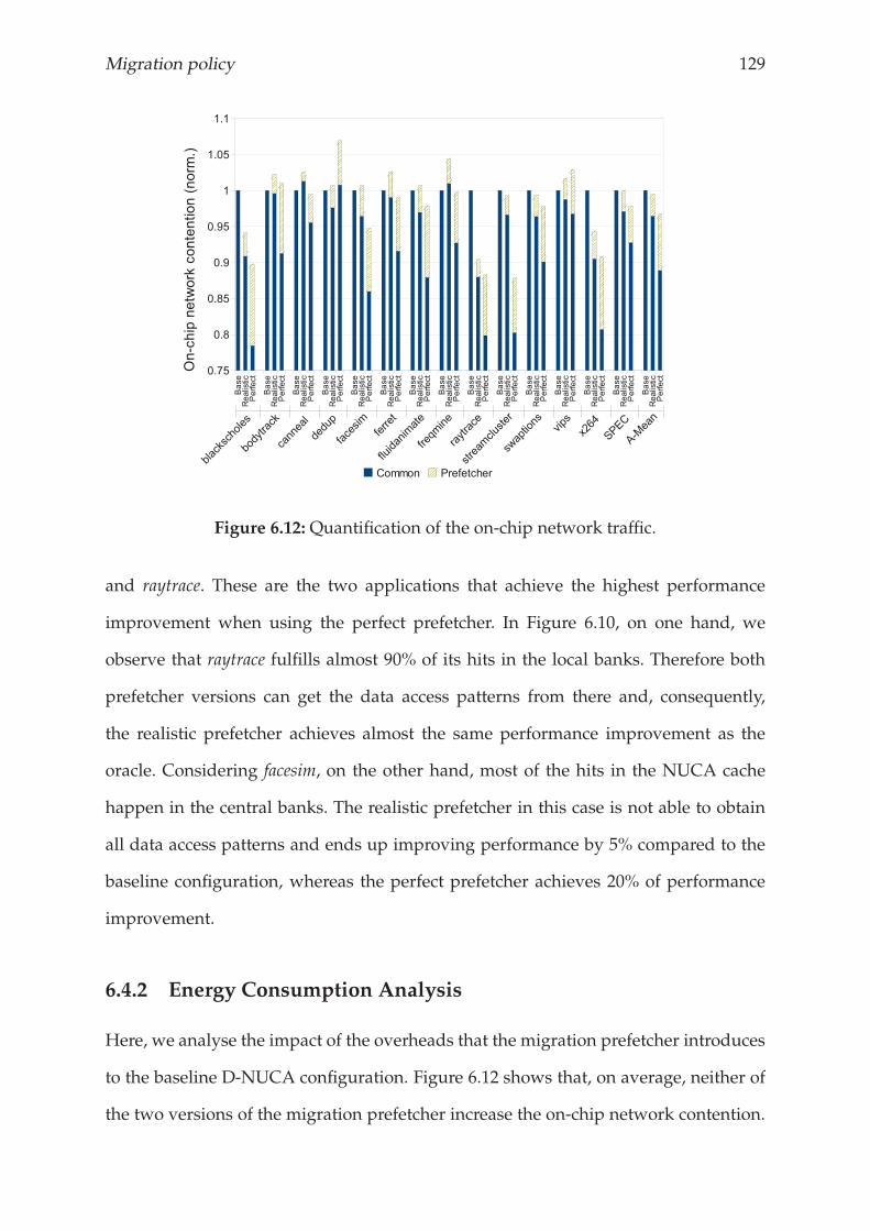
Migration policy 129
Figure 6.12: Quantification of the on-chip network traffic.
and raytrace. These are the two applications that achieve the highest performance
improvement when using the perfect prefetcher. In Figure 6.10, on one hand, we
observe that raytrace fulfills almost 90% of its hits in the local banks. Therefore both
prefetcher versions can get the data access patterns from there and, consequently,
the realistic prefetcher achieves almost the same performance improvement as the
oracle. Considering facesim, on the other hand, most of the hits in the NUCA cache
happen in the central banks. The realistic prefetcher in this case is not able to obtain
all data access patterns and ends up improving performance by 5% compared to the
baseline configuration, whereas the perfect prefetcher achieves 20% of performance
improvement.
6.4.2 Energy Consumption Analysis
Here, we analyse the impact of the overheads that the migration prefetcher introduces
to the baseline D-NUCA configuration. Figure 6.12 shows that, on average, neither of
the two versions of the migration prefetcher increase the on-chip network contention.
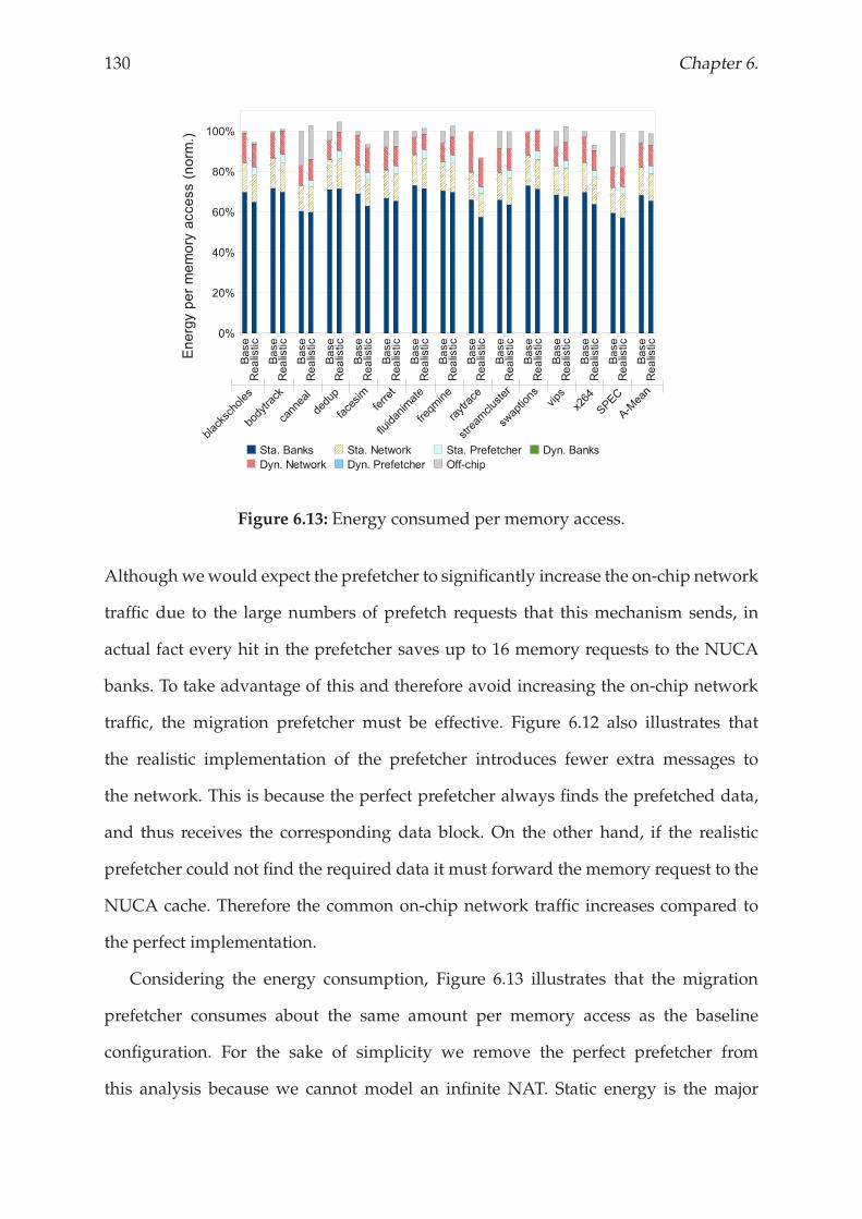
130 Chapter 6.
Figure 6.13: Energy consumed per memory access.
Although wewould expect the prefetcher to significantly increase the on-chip network
traffic due to the large numbers of prefetch requests that this mechanism sends, in
actual fact every hit in the prefetcher saves up to 16 memory requests to the NUCA
banks. To take advantage of this and therefore avoid increasing the on-chip network
traffic, the migration prefetcher must be effective. Figure 6.12 also illustrates that
the realistic implementation of the prefetcher introduces fewer extra messages to
the network. This is because the perfect prefetcher always finds the prefetched data,
and thus receives the corresponding data block. On the other hand, if the realistic
prefetcher could not find the required data it must forward the memory request to the
NUCA cache. Therefore the common on-chip network traffic increases compared to
the perfect implementation.
Considering the energy consumption, Figure 6.13 illustrates that the migration
prefetcher consumes about the same amount per memory access as the baseline
configuration. For the sake of simplicity we remove the perfect prefetcher from
this analysis because we cannot model an infinite NAT. Static energy is the major
Migration policy 131
contributor to the overall energy consumed by caches, and this case is not an
exception. In general, we find that although the migration prefetcher introduces
264 KBytes to implement the required structures, it achieves a significant enough
reduction in dynamic energy consumption in the on-chip network to counterbalance
these overheads. As happens with the on-chip traffic, the amount of energy consumed
by the prefetcher depends on its effectiveness. We can clearly see that the migration
prefetcher achieves the highest reduction in energy consumption per memory access
in applications where it also obtains the highest performance benefits, like facesim,
raytrace or x264.
6.4.3 Summary
This section has analysed the performance and energy consumption of our migration
prefetcher, showing that the realistic implementation achieves an overall speed-up of
4% across all benchmarks, up to 17% in the case of raytrace. Furthermore, an analysis
of the banks that are accessed in each scheme shows that it is able to service significant
numbers of hits from within the prefetcher itself, providing further evidence of the
benefits that this technique can bring.
6.5 RELATED WORK
Prefetching is a well known technique for boosting program performance by moving
data to a nearer cache level to the core before it is required by the execution units of the
processor [16, 78]. Themost relevant approaches to our work are Tagged Prefetching [73]
that tries to capture accesses to consecutive memory lines, Stride Prefetching [20]
that tries to capture accesses at the same distance from one to next and Correlation
Prefetching [66] that tries to identify groups of memory accesses that are related under
a common pattern against time.
Prefetching in a NUCA was first analysed by Beckmann and Wood [9]. They
132 Chapter 6.
evaluated stride-based prefetching between the L2 cache and memory and between
L1 and L2 caches. In this thesis, we apply prefetching in the NUCA cache to move
data that is likely to be accessed close to the requesting core, but at the NUCA level.
This mechanism, therefore, does not provoke replacements with prefetched data.
Migration techniques in D-NUCA have been widely analysed in the literature.
Kim et al. [41] introduced the D-NUCA concept on uniprocessors and proposed a
simple migration mechanism known as gradual promotion. This approach begins with a
hit in the NUCA cache, and moves the requested data one-step closer to the processor
that initiated the memory request. Beckmann and Wood [9] demonstrated that block
migration is less effective for CMPs because 40-60% of hits in commercial workloads
are satisfied in the central banks. In this thesis, we show how prefetching can help
migration to reduce the hit rate in the non-optimal banks.
Eisley et al. [28] proposed a scalable migration technique that tries to allocate
data in free/invalid cache slots instead of sending data off-chip. Kandemir et al. [39]
took a different point of view. They observed that 50% of data fetched from of-chip
memory to a shared L2 NUCA cache was used more heavily by a different core
from the one that originally requested the data. Based on this observation, they
focused on minimizing the number of migrations with a placement mechanism that
tries to place data in an optimal position. In the same vein, Hammoud et al. [30]
predicted the optimal location of data bymonitoring the behavior of programs. Finally,
Chaudhuri [19] proposed a coarse-grained data migration mechanism assisted by the
operating system that monitors access patterns to decide where and when an entire
page of data should be migrated.
A common characteristic of these migration techniques is that they move data to
the optimal position with the cache to reduce the access latency for future accesses to
the same data. In our work, however, we analyse related data to anticipate migrations,
and thus reduce access latency for future accesses not only to the same data, but also to
its followers. Moreover, although in this thesis we analysed this technique with gradual
Migration policy 133
migration, we could implement it in conjunction with any other migration technique
proposed in the literature.
6.6 CONCLUSIONS
Existing data migration policies for NUCA caches succeed in concentrating the
most frequently accessed data in the NUCA banks with the smallest access latency.
However, there is still a significant percentage of hits in the NUCA cache that are
resolved in slower banks.
In order to address this situation, we have proposed a migration prefetcher. This
recognizes data access patterns to the NUCA cache, and then anticipates data
migrations, prefetching a copy of data and holding it close to the core. Using the
migration prefetcher, therefore, the number of hits in the NUCA cache that take the
optimal access latency increases. We find that a perfect prefetcher reduces the NUCA
access latency, on average, by 30%, and improves performance by 7% compared to the
baseline configuration. Assuming a more realistic approach, the migration prefetcher
still achieves an overall latency reduction of 15%, and outperforms the baseline
configuration by 4%, or up to 17% in one application.

134 Chapter 6.
Chapter 7
Conclusions and future work
This chapter summarizes the main conclusions of this thesis and outlines areas for future work.

Conclusions and future work 137
7.1 CONCLUSIONS
The growing influence of wire delays in cache design has meant that access latency
to last-level cache banks are no longer constant. NUCA cache memories address
this situation by allowing banks close to the requesting processor to have smaller
latencies than other banks that are further away. These cache architectures have been
traditionally classified based on their placement decisions as static (S-NUCA) or
dynamic (D-NUCA). In this thesis, we have focused on D-NUCA as it exploits the
dynamic features that NUCA caches offer, like data migration. The flexibility that
D-NUCA provides, however, raises new challenges that hardens the management
of this kind of cache architectures in CMP systems. We have identified these new
challenges and tackled them from the point of view of the four NUCA policies:
replacement, access, placement and migration.
Chapter 3 presents three different techniques that deal with the challenges related
to the replacement policy in a D-NUCA cache: Last Bank, LRU-PEA and The Auction.
Data migration makes most frequently accessed data blocks to be concentrated on the
banks that are closer to the processors. This creates big differences in the average usage
rate of the NUCA banks, being the banks that are close to the processors the most
accessed banks, while the banks that are further away are not accessed so often. Upon
a replacement in a particular bank of the NUCA cache, the probabilities of the evicted
data block to be reused by the programwill differ if its last location in the NUCA cache
was a bank that are close to the processors, or not. The decentralized nature of NUCA,
however, prevents a NUCA bank from knowing that other bank is constantly evicting
data blocks that are later being reused. To address this situation, we first propose
Last Bank. This technique introduces an extra bank in the NUCA cache to deal with
the evicted data from the other banks. Although using this technique is particularly
effective with small NUCA caches, as cache size grows, it cannot reach the potential
benefits. Then, we propose LRU-PEA. This technique classifies data blocks relying on
138 Chapter 7.
their last migration action (promoted, demoted or none), and modifies the traditional
LRU replacement policy to prioritize promoted data over the other categories. We
find that using this technique as replacement policy, we increase performance benefits
by 8% over the baseline configuration. Finally, we propose The Auction. This is a
framework that allows architects for implementing auction-like replacement policies
in future D-NUCA cache architectures. The Auction spreads replacement decisions
that have been taken in a single bank to the whole NUCA cache. Therefore, this enables
the replacement policy to select the most appropriate victim data block from the whole
NUCA cache. The implemented auction approaches increase performance benefits by
6-8% and reduce energy consumed by 4% compared to the baseline configuration.
The challenges in the access policy has been tackled in the Chapter 4. As data blocks
can bemapped in multiple banks within the NUCA cache. Finding the requesting data
in a D-NUCA cache is a difficult task. In addition, data can freely move between these
banks, thus the search scheme must look up all banks where the requesting data block
can be mapped to ascertain if it is in the NUCA cache, or not. We have proposed
HK-NUCA. This is a search scheme that uses home knowledge to effectively reduce the
average number of messages introduced to the on-chip network to satisfy a memory
request. On average, HK-NUCA outperforms previous access schemes for D-NUCA
caches by 6%, and reduces the dynamic energy consumed by the memory system by
40%.
IBM® have already succeeded in integrating eDRAM technology in the on-chip
memory cache hierarchy of their latest processor, POWER7. This could be considered
the starting point to integrate more sophisticated hybrid cache structures in the near
future. Chapter 5 describes the implementation of a hybrid NUCA cache. We have
proposed a novel placement policy that accomodates both memory technologies,
SRAM and eDRAM, in a single NUCA cache. This takes advantage of the fast SRAM
caches to store there the most accessed data blocks, while other data that have not
been accessed, or has been evicted from SRAM banks are stored in the eDRAM
Conclusions and future work 139
banks. We have analysed this placement policy and shown that a well-balanced hybrid
NUCA cache achieves similar performance results as the baseline, but consumes 10%
less power and occupies about 15% less area in the chip. Finally, we have analysed
different alternatives to take advantage of the area reduction we got by using the
hybrid architecture that lead us to get performance benefits up to 10%.
Finally, Chapter 6 presents The Migration Prefetcher, a technique that anticipates
data migrations. This mechanism recognizes access patterns based on the history, and
promotes the potential follower of the current memory access before the next memory
access actually happens. When The Migration Prefetcher hits on the prediction, the
memory access finishes in few cycles, instead of more than one hundred, that is what
it takes when the data block is in the furthest bank. The migration prefetcher achieves
an overall latency reduction of 15%, and outperforms the baseline configuration by up
to 17%.
7.2 FUTURE WORK
Future CMPs will incorporate larger last-level cache memories into the chip. Current
research shows two different paths to deal with future larger cache memories: (1) by
integrating a traditional NUCA cache memory that occupies more die area, or (2)
by stacking multiple multiple dies, which is commonly known as NUCA 3D [13].
Memory can be stacked directly on top of a microprocessor through 3D integration
resulting in significant reduction in wire delay between the processor and the memory.
The stacked dies usually communicate with vertical buses called through-silicon via
(TSV). These buses define the entrance point to the NUCA cache. We believe that the
techniques proposed in this thesis could be easily applicable to this new architecture
with minimum adjustments.
Reducing network traffic on D-NUCA or not increasing it too much has been a
common constraint in all the proposed techniques of this thesis. We consider that
140 Chapter 7.
efficientlymanaging the on-chip network that interconnects all NUCAbanks is crucial.
Network-on-Chip (NoC) has emerged as an emerging topic in CMPs [75]. Introducing
support from the NoC to manage a NUCA architecture will be part of the future work.
For instance, router can assign different priorities for messages introduced by the
NUCApolicies. Then, high-priority messages would be quickly sent, and thus provide
high performance, while low-priority messages would be efficient in terms of energy
consumption.
Another interesting architecture to exploit with NUCA caches are Graphics
Processing Units (GPUs). These are specialized processors that typically integrate
hundreds of cores in a single chip [44]. One of the main challenges in GPUs is to
optimize data locality. In terms of energy consumption, fetching operands actually
costs more than the computing on them [24]. Thus, optimizing data movements to
leverage data locality on GPUs could be a very interesting future work.
Chapter 5 shows the implementation of a SRAM / eDRAM hybrid NUCA cache.
Recent works analysed incorporating other technologies into the chip, like MRAM
or PCM [54]. Integrating a hybrid NUCA cache with these technologies on a NUCA
cache would be a challenging task. As with eDRAM, PCM and MRAM have several
strong features to emphasize, but also have some drawbacks to hide. Therefore,
accomodating novel technologies into the chip could also be considered as part of
our future work.
Managing Dynamic Non-Uniform Cache Architectures 141
REFERENCES
[1] Niket Agarwal, Li-Shiuan Peh, and Niraj Jha. Garnet: A detailed interconnection
network model inside a full-system simulation framework. Technical Report
CE-P08-001, Princeton University, 2008.
[2] V. Agarwal, M. S. Hrishikesh, S. W. Keckler, and D. Burger. Clock rate vs. ipc: The
end of the road for conventional microprocessors. In Procs. of the 27th International
Symposium on Computer Architecture, 2000.
[3] S. Akioka, F. Li, K. Malkowski, P. Raghavan, M. Kandemir, and M. J. Irwin. Ring
data location prediction scheme for non-uniform cache architectures. In Procs. of
the International Conference on Computer Design, 2008.
[4] David H. Albonesi. Editor in chief’s message: Truly "hot" chips–do we still care?
Micro, IEEE, 27(2):4 –5, march-april 2007.
[5] J. Alghazo, A. Akaaboune, and N. Botros. Sf-lru cache replacement algorithm.
In Records of the International Workshop on Memory Technology, Design and Testing,
2004.
[6] O. Azizi, A. Mahesri, B. C. Lee, S. J. Patel, andM. Horowitz. Energy-performance
tradeoffs in processor architecture and circuit design: A marginal cost analysis.
In Procs. of the 37th International Symposium on Computer Architecture, 2010.
[7] A. Bardine, P. Foglia, G. Gabrielli, and C. A. Prete. Analysis of static and dynamic
energy consumption in nuca caches: Initial results. In Procs. of the Workshop on
Memory Performance: Dealing with Applications, Systems and Architecture, 2007.
[8] B. M. Beckmann, M. R. Marty, and D. A. Wood. Asr: Adaptive selective
replication for cmp caches. In Procs. of the 39th Annual IEEE/ACM International
Symposium of Microarchitecture, 2006.
142 References
[9] B. M. Beckmann and D. A. Wood. Managing wire delay in large
chip-multiprocessor caches. In Procs. of the 37th International Symposium on
Microarchitecture, 2004.
[10] L. A. Belady. A study of replacement algorithms for virtual-storage computer.
IMB Systems Journal, 5(2), 1966.
[11] Benchmarks. Spec cpu2006. In http : //www.spec.org/cpu2006, 2006.
[12] C. Bienia, S. Kumar, J. P. Singh, and K. Li. The parsec benchmark suite:
Characterization and architectural implications. In Procs. of the International
Conference on Parallel Architectures and Compilation Techniques, 2008.
[13] B. Black, M. Annavaram, N. Brekelbaum, J. DeVale, L. Jiang, G. H. Loh,
D. McCaule, P. Morrow, D. W. Nelson, D. Pantuso, P. Reed, J. Rupley, S. Shankar,
J. Shen, and C. Webb. Die stacking (3d) microarchitecture. In Procs. of the 39th
Annual IEEE/ACM International Symposium on Microarchitecture, 2006.
[14] E. Bolotin, Z. Guz, I. Cidon, R. Ginosar, and A. Kolodny. The power of priority:
Noc based distributed cache coherency. In Procs. of the 1st International Symposium
on Networks-on-Chip, 2007.
[15] S. Y. Borkar, P. Dubey, K. C. Kahn, D. J. Kuck, H. Mulder, S. S. Pawlowski, and
J. R. Rattner. Platform 2015: Intel processor and platform evolution for the next
decade. Technology@Intel Magazine, 2005.
[16] S. Byna, Y. Chen, and X. H. Sun. Taxonomy of data prefetching for multicore
processors. Journal of Computer Science and Technology, 24(3):Pages 405–417, May
2009.
[17] J. Chang and G. S. Sohi. Cooperative caching for chip multiprocessors. In Procs.
of the 33rd International Symposium on Computer Architecture, 2006.
Managing Dynamic Non-Uniform Cache Architectures 143
[18] J. Chang and G. S. Sohi. Cooperative cache partitioning for chip multiprocessors.
In Procs. of the 21st ACM International Conference on Supercomputing, 2007.
[19] M. Chaudhuri. Pagenuca: Selected policies for page-grain locality management
in large shared chip-multiprocessors. In Procs. of the 15th International Symposium
on High-Performance Computer Architecture, 2009.
[20] T. F. Chen and J. L. Baer. Effective hardware-based data prefetching for
high-performance processors. IEEE Transactions on Computers, 44(5), 1995.
[21] Z. Chishti, M. D. Powell, and T. N. Vijaykumar. Distance associativity for
high-performance energy-efficient non-uniform cache architectures. In Procs. of
the 36th International Symposium on Microarchitecture, 2003.
[22] Z. Chishti, M. D. Powell, and T. N. Vijaykumar. Optimizing replication,
communication, and capacity allocation in cmps. In Procs. of the 32nd International
Symposium on Computer Architecture, 2005.
[23] C. Corwell, C. A. Moritz, and W. Burleson. Improved modeling and data
migration for dynamic non-uniform cache accesses. In Procs. of the 2nd Workshop
on Duplicating, Deconstructing and Debunking, 2003.
[24] W Dally. Power, programmability, and granularity: The challenges of exascale
computing. In Procs. of the 25th IEEE International Parallel and Distributed
Processing Symposium (IPDPS), 2011.
[25] P. Dubey. A platform 2015 workload model: Recognition, mining and synthesis
moves computers to the era of tera. In Intel White Paper, Intel Corporation, 2005.
[26] H. Dybdahl and P. Stenström. An adaptive shared/private nuca cache
partitioning scheme for chip multiprocessors. In Procs. of the 13th International
Symposium on High-Performance Computer Architecture, 2007.
144 References
[27] H. Dybdahl, P. Stenström, and L. Natvig. An lru-based replacement algorithm
augmented with frequency of access in shared chip-multiprocessor caches.
Computer Architecture News, 35, 2007.
[28] N. Eisley, L. S. Peh, and L. Shang. Leveraging on-chip networks for cache
migration in chip multiprocessors. In Procs. of the 17th International Conference
on Parallel Architectures and Compilation Techniques, 2008.
[29] E. Grochowski, R. Ronen, J. Shen, and H. Wang. Best of both latency and
throughput. In Procs. of the 22nd Intl. Conference on Computer Design, 2004.
[30] M. Hammoud, S. Cho, and R. Melhem. Acm: An efficient approach for managing
shared caches in chip multiprocessors. In Procs. of the 4th Intl. Conference on High
Performance and Embedded Architectures, 2009.
[31] M. Hammoud, S. Cho, and R. Melhem. Dynamic cache clustering for chip
multiprocessors. In Procs. of the Intl. Conference on Supercomputing, 2009.
[32] N. Hardavellas, M. Ferdman, B. Falsafi, and A. Ailamaki. Reactive nuca:
Near-optimal block placement and replication in distributed caches. In Procs.
of the 36th International Symposium on Computer Architecture, 2009.
[33] E. Herrero, J. Gonzalez, and R. Canal. Distributed cooperative caching. In
Procs. of the 17th International Conference on Parallel Architectures and Compilation
Techniques, 2008.
[34] E. Herrero, J. Gonzalez, and R. Canal. Elastic cooperative caching: An
autonomous dynamically adaptive memory hierarchy for chip multiprocessors.
In Procs. of the 37th International Symposium on Computer Architecture, 2010.
[35] J. Huh, D. Burger, and S. W. Keckler. Exploring the design space of future cmps.
In Procs. of the 10th Intl. Conf. on Parallel Architectures and Compilation Techniques
(PACT), 2001.
Managing Dynamic Non-Uniform Cache Architectures 145
[36] J. Huh, C. Kim, H. Shafi, L. Zhang, D. Burger, and S. W. Keckler. A nuca substrate
for flexible cmp cache sharing. In Procs. of the 19th ACM International Conference
on Supercomputing, 2005.
[37] Intel. The scc platform overview. In Technical Report, May 2010.
[38] N. P. Jouppi. Improving direct-mapped cache performance by the addition of
a small fully-associative cache and prefetch buffers. In Procs. of the 17th annual
international symposium on Computer Architecture, 1990.
[39] M. Kandemir, F. Li, M. J. Irwin, and S. W. Son. A novel migration-based
nuca design for chip multiprocessors. In Procs. of the International Conference on
Supercomputing, 2008.
[40] M. Kharbutli and Y. Solihin. Counter-based cache replacement algorithms. In
Procs. of the 23rd International Conference on Computer Design, 2005.
[41] C. Kim, D. Burger, and S. W. Keckler. An adaptive, non-uniform cache structure
for wire-delay dominated on-chip caches. In Procs. of the 10th Intl. Conf. on
Architectural Support for Programming Languages and Operating Systems, 2002.
[42] P. Kongetira, K. Aingaran, and K. Olukotun. Niagara: a 32-way multithreaded
sparc processor. In IEEE Micro, March 2005.
[43] H. Q. Le, W. J. Starke, J. S. Fields, F. P. O’Connell, D. Q. Nguyen, B. J. Ronchetti,
W. M. Sauer, E. M. Schwarz, and M. T. Vaden. Ibm power6 microarchitecture.
IBM Journal, November 2007.
[44] E. Lindholm, J. Nickolls, S. Oberman, and J. Montrym. Nvidia tesla: A unified
graphics and computing architecture. Micro, IEEE, 28(2):39 –55, march-april 2008.
[45] J. Lira, T.M. Jones, C. Molina, and A. González. The migration prefetcher:
Anticipating data promotion in dynamic nuca caches. In Procs. of the International
Conference on Parallel Architectures and Compilation Techniques (PACT), 2011.
146 References
[46] J. Lira, C. Molina, D. Brooks, and A. González. Implementing a hybrid sram /
edram nuca architecture. In Procs. of the 18th Annual International Conference on
High Performance Computing (HiPC’11), 2011.
[47] J. Lira, C. Molina, and A. González. Analysis of non-uniform cache architecture
policies for chip-multiprocessors using the parsec benchmark suite. In Procs. of
the 2nd Workshop on Managed Many-Core Systems (MMCS), 2009.
[48] J. Lira, C. Molina, and A. González. Last bank: dealing with address reuse
in non-uniform cache architecture for cmps. In Procs. of the 15th International
Euro-Par Conference (Euro-Par), 2009.
[49] J. Lira, C. Molina, and A. González. Lru-pea: A smart replacement policy
for non-uniform cache architectures on chip multiprocessors. In Procs. of the
International Conference on Computer Design (ICCD), 2009.
[50] J. Lira, C. Molina, and A. González. Performance analysis of non-uniform cache
architecture policies for chip-multiprocessors using the parsec v2.0 benchmark
suite. In Procs. of the XX Jornadas de Paralelismo, 2009.
[51] J. Lira, C. Molina, and A. González. The auction: Optimizing banks usage in
non-uniform cache architectures. In Procs. of the 24th International Conference on
Supercomputing (ICS), 2010.
[52] J. Lira, C. Molina, and A. González. Hk-nuca: Boosting data searches in dynamic
non-uniform cache architectures for chip multiprocessors. In Procs. of the 25th
IEEE International Parallel and Distributed Processing Symposium (IPDPS), 2011.
[53] R. Low. Microprocessor trends: multicore, memory, and power developments.
Embedded Computing Design, September 2005.
[54] N. Madan, L. Zhao, N. Muralimanohar, A. Udipi, R. Balasubramonian, R. Iyer,
S. Makineni, and D. Newell. Optimizing communication and capacity in a
Managing Dynamic Non-Uniform Cache Architectures 147
3d stacked reconfigurable cache hierarchy. In Procs. of the 15th International
Symposium on High-Performance Computer, 2009.
[55] P. S. Magnusson, M. Christensson, J. Eskilson, D. Forsgren, G. Hallberg,
J. Högberg, F. Larsson, A.Moestedt, and B.Werner. Simics: A Full System Simulator
Platform, volume 35-2, pages 50–58. Computer, 2002.
[56] M. M. K. Martin, D. J. Sorin, B. M. Beckmann, M. R. Marty, M. Xu, A. R.
Alameldeen, K. E. Moore, M. D. Hill, and D. A. Wood. Multifacet’s
general execution-driven multiprocessor simulator (gems) toolset. In Computer
Architecture News, 2005.
[57] D. Matzke. Will physical scalability sabotage performance gains? IEEE Computer,
September 1997.
[58] C. McNairy and R. Bhatia. Montecito: A dual-core, dual-thread itanium
processor. IEEE Micro, 25(2), March-April 2005.
[59] J. Merino, V. Puente, and J. A. Gregorio. Sp-nuca: A cost effective dynamic
non-uniform cache architecture. ACM SIGARCH Computer Architecture News,
36(2):64–71, May 2008.
[60] Micron. System power calculator. In http : //www.micron.com/, 2009.
[61] D. Molka, D. Hackenberg, R. Schone, and M. S. Muller. Memory performance
and cache coherency effects on an intel nehalemmultiprocessor system. In Procs.
of the International Conference on Parallel Architectures and Compilation Techniques.
[62] G. E. Moore. The future of integrated electronics. In Fairchild Semiconductor
internal publication, 1964.
[63] N. Muralimanohar and R. Balasubramonian. Interconnect design considerations
for large nuca caches. In Procs. of the 34th International Symposium on Computer
Architecture, 2007.
148 References
[64] N. Muralimanohar, R. Balasubramonian, and N. P. Jouppi. Cacti 6.0: A tool
to understand large caches. Technical report, University of Utah and Hewlett
Packard Laboratories, 2007.
[65] N. Muralimanohar, R. Balasubramonian, and N. P. Jouppi. Optimizing nuca
organizations and wiring alternatives for large caches with cacti 6.0. In Procs.
of the 40th International Symposium on Microarchitecture, 2007.
[66] K. J. Nesbit and J. E. Smith. Data cache prefetching using a global history buffer.
In Procs. of the 10th Intl. Symp. on High-Performance Computer Architecture, 2004.
[67] T. K. Prakash and L. Peng. Performance characterization of spec cpu2006
benchmarks on intel core 2 duo processor. ISAST Transactions on Computers and
Software Engineering, 2(1):36–41, 2008.
[68] M. K. Qureshi, A. Jaleel, and Y. N. Patt. Adaptive insertion policies for
high-performance caching. In Procs. of the 34th International Symposium on
Computer Architecture, 2007.
[69] M. K. Qureshi, J. Karidis, M. Franceschini, V. Srinivasan, L. Lastras, and B. Abali.
Enhancing lifetime and security of phase change memories via start-gap wear
leveling. In Procs. of the 42nd International Symposium on Microarchitecture, 2009.
[70] M. K. Qureshi, V. Srinivasan, and J. A. Rivers. Scalable high-performance main
memory system using phase-change memory technology. In Procs. of the 32th
International Symposium on Computer Architecture, 2009.
[71] M. K. Qureshi, M. A. Suleman, and Y. N. Patt. Line distillation: Increasing cache
capacity by filtering unused words in cache lines. In Procs. of the 13th International
Symposium of High-Performance Computer Architecture, 2007.
[72] R. Ricci, S. Barrus, and R. Balasubramonian. Leveraging bloom filters for smart
Managing Dynamic Non-Uniform Cache Architectures 149
search within nuca caches. In Procs. of the 7th Workshop on Complexity-Effective
Design, 2006.
[73] A. J. Smith. Cache memories. ACM Computing Surveys, 14(3), 1982.
[74] G. Sun, X. Dong, Y. Xie, J. Li, and Y. Chen. A novel 3d stacked mram
cache architecture for cmps. In Procs. of the 15th International Symposium on
High-Performance Computer, 2009.
[75] O. Tayan. Networks-on-chip: Challenges, trends and mechanisms for
enhancements. In Procs. of the International Conference on Information and
Communication Technologies, 2009.
[76] S. Thoziyoor, N. Muralimanohar, J. H. Ahn, and N. P. Jouppi. Cacti 5.1. Technical
report, HP, 2008.
[77] A. Valero, J. Sahuquillo, S. Petit, V. Lorente, R. Canal, P. Lopez, and J. Duato. An
hybrid edram/sram macrocell to implement first-level data caches. In Procs. of
the 42nd International Symposium on Microarchitecture, 2009.
[78] S. VanderWiel and D. J. Lilja. A survey of data prefetching techniques. In Procs.
of the 23rd International Symposium on Computer Architecture, 1996.
[79] S. Vangal, J. Howard, G. Ruhl, S. Dighe, H. Wilson, J. Tschanz, D. Finnan, P. Iyer,
A. Singh, T. Jacob, S. Jain, S. Venkataraman, Y. Hoskote, and N. Borkar. An
80-tile 1.28tflops network-on-chip in 65nm cmos. In Procs. of the IEEE International
Solid-State Circuits Conference, 2007.
[80] H. S. Wang, X. Zhu, L. S. Peh, and S. Malik. Orion: A power-performance
simulator for interconnection networks. In Procs. of the 35th International
Symposium on Microarchitecture, 2002.
[81] D. Wendel, R. Kalla, R. Cargoni, J. Clables, J. Friedrich, R. Frech, J. Kahle,
B. Sinharoy, W. Starke, S. Taylor, S. Weitzel, S. G. Chu, S. Islam, and V. Zyuban.
150 References
The implementation of power7: A highly parallel and scalable multi-core
high-end server processor. In Procs. of the IEEE International Solid-State Circuits
Conference (ISSCC), 2010.
[82] T. F. Wenisch, R. E. Wunderlich, M. Ferdman, A. Ailamaki, B. Falsafi, and J. C.
Hoe. Simflex: Statistical sampling of computer system simulation. IEEE Micro,
26(4):18–31, 2006.
[83] S.Wilton andN. P. Jouppi. CACTI: An Enhanced Cache Access and Cycle TimeModel,
volume 31-5, pages 677–688. IEEE Journal of Solid-State Circuits, 1996.
[84] W. Wong and J. Baer. Modified lru policies for improving second-level cache
behavior. In Procs. of the 6th International Symposium on High-Performance Computer
Architecture, 2000.
[85] X. Wu, J. Li, L. Zhang, E. Speight, R. Rajamony, and Y. Xie. Hybrid cache
architecture with disparate memory technologies. In Procs. of the 32th International
Symposium on Computer Architecture, 2009.
[86] M. Zhang and K. Asanovic. Victim replication: Maximizing capacity while
hiding wire delay in tiled chip multiprocessors. In Procs. of the 32nd International
Symposium on Computer Architecture, 2005.
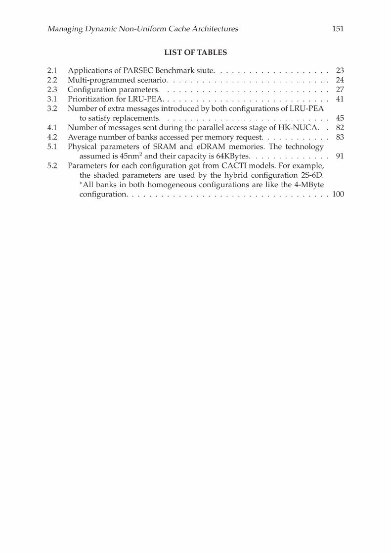
Managing Dynamic Non-Uniform Cache Architectures 151
LIST OF TABLES
2.1 Applications of PARSEC Benchmark siute. . . . . . . . . . . . . . . . . . . . 232.2 Multi-programmed scenario. . . . . . . . . . . . . . . . . . . . . . . . . . . . 242.3 Configuration parameters. . . . . . . . . . . . . . . . . . . . . . . . . . . . . 273.1 Prioritization for LRU-PEA. . . . . . . . . . . . . . . . . . . . . . . . . . . . . 413.2 Number of extra messages introduced by both configurations of LRU-PEA
to satisfy replacements. . . . . . . . . . . . . . . . . . . . . . . . . . . . . 454.1 Number of messages sent during the parallel access stage of HK-NUCA. . 824.2 Average number of banks accessed per memory request. . . . . . . . . . . . 835.1 Physical parameters of SRAM and eDRAM memories. The technology
assumed is 45nm2 and their capacity is 64KBytes. . . . . . . . . . . . . . 915.2 Parameters for each configuration got from CACTI models. For example,
the shaded parameters are used by the hybrid configuration 2S-6D.∗All banks in both homogeneous configurations are like the 4-MByteconfiguration. . . . . . . . . . . . . . . . . . . . . . . . . . . . . . . . . . . 100

152 List of Tables
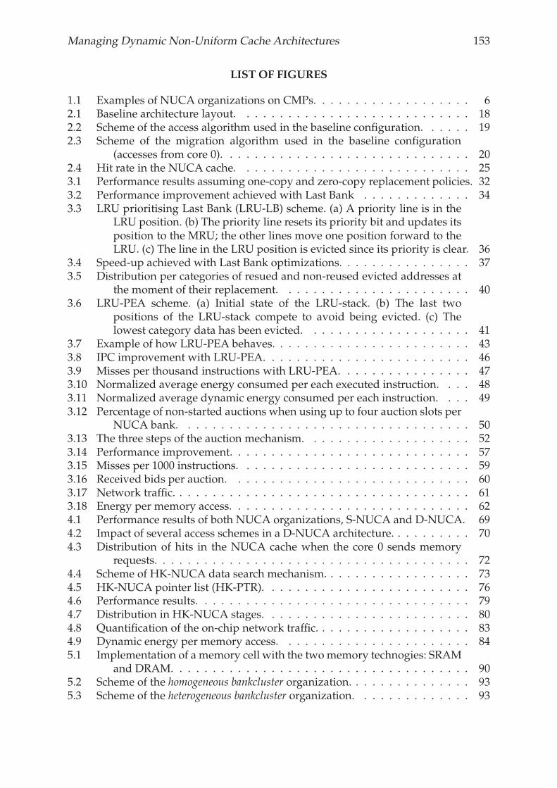
Managing Dynamic Non-Uniform Cache Architectures 153
LIST OF FIGURES
1.1 Examples of NUCA organizations on CMPs. . . . . . . . . . . . . . . . . . . 62.1 Baseline architecture layout. . . . . . . . . . . . . . . . . . . . . . . . . . . . 182.2 Scheme of the access algorithm used in the baseline configuration. . . . . . 192.3 Scheme of the migration algorithm used in the baseline configuration
(accesses from core 0). . . . . . . . . . . . . . . . . . . . . . . . . . . . . . 202.4 Hit rate in the NUCA cache. . . . . . . . . . . . . . . . . . . . . . . . . . . . 253.1 Performance results assuming one-copy and zero-copy replacement policies. 323.2 Performance improvement achieved with Last Bank . . . . . . . . . . . . . 343.3 LRU prioritising Last Bank (LRU-LB) scheme. (a) A priority line is in the
LRU position. (b) The priority line resets its priority bit and updates itsposition to the MRU; the other lines move one position forward to theLRU. (c) The line in the LRU position is evicted since its priority is clear. 36
3.4 Speed-up achieved with Last Bank optimizations. . . . . . . . . . . . . . . . 373.5 Distribution per categories of resued and non-reused evicted addresses at
the moment of their replacement. . . . . . . . . . . . . . . . . . . . . . . 403.6 LRU-PEA scheme. (a) Initial state of the LRU-stack. (b) The last two
positions of the LRU-stack compete to avoid being evicted. (c) Thelowest category data has been evicted. . . . . . . . . . . . . . . . . . . . 41
3.7 Example of how LRU-PEA behaves. . . . . . . . . . . . . . . . . . . . . . . . 433.8 IPC improvement with LRU-PEA. . . . . . . . . . . . . . . . . . . . . . . . . 463.9 Misses per thousand instructions with LRU-PEA. . . . . . . . . . . . . . . . 473.10 Normalized average energy consumed per each executed instruction. . . . 483.11 Normalized average dynamic energy consumed per each instruction. . . . 493.12 Percentage of non-started auctions when using up to four auction slots per
NUCA bank. . . . . . . . . . . . . . . . . . . . . . . . . . . . . . . . . . . 503.13 The three steps of the auction mechanism. . . . . . . . . . . . . . . . . . . . 523.14 Performance improvement. . . . . . . . . . . . . . . . . . . . . . . . . . . . . 573.15 Misses per 1000 instructions. . . . . . . . . . . . . . . . . . . . . . . . . . . . 593.16 Received bids per auction. . . . . . . . . . . . . . . . . . . . . . . . . . . . . 603.17 Network traffic. . . . . . . . . . . . . . . . . . . . . . . . . . . . . . . . . . . . 613.18 Energy per memory access. . . . . . . . . . . . . . . . . . . . . . . . . . . . . 624.1 Performance results of both NUCA organizations, S-NUCA and D-NUCA. 694.2 Impact of several access schemes in a D-NUCA architecture. . . . . . . . . . 704.3 Distribution of hits in the NUCA cache when the core 0 sends memory
requests. . . . . . . . . . . . . . . . . . . . . . . . . . . . . . . . . . . . . . 724.4 Scheme of HK-NUCA data search mechanism. . . . . . . . . . . . . . . . . . 734.5 HK-NUCA pointer list (HK-PTR). . . . . . . . . . . . . . . . . . . . . . . . . 764.6 Performance results. . . . . . . . . . . . . . . . . . . . . . . . . . . . . . . . . 794.7 Distribution in HK-NUCA stages. . . . . . . . . . . . . . . . . . . . . . . . . 804.8 Quantification of the on-chip network traffic. . . . . . . . . . . . . . . . . . . 834.9 Dynamic energy per memory access. . . . . . . . . . . . . . . . . . . . . . . 845.1 Implementation of a memory cell with the twomemory technogies: SRAM
and DRAM. . . . . . . . . . . . . . . . . . . . . . . . . . . . . . . . . . . . 905.2 Scheme of the homogeneous bankcluster organization. . . . . . . . . . . . . . . 935.3 Scheme of the heterogeneous bankcluster organization. . . . . . . . . . . . . . 93
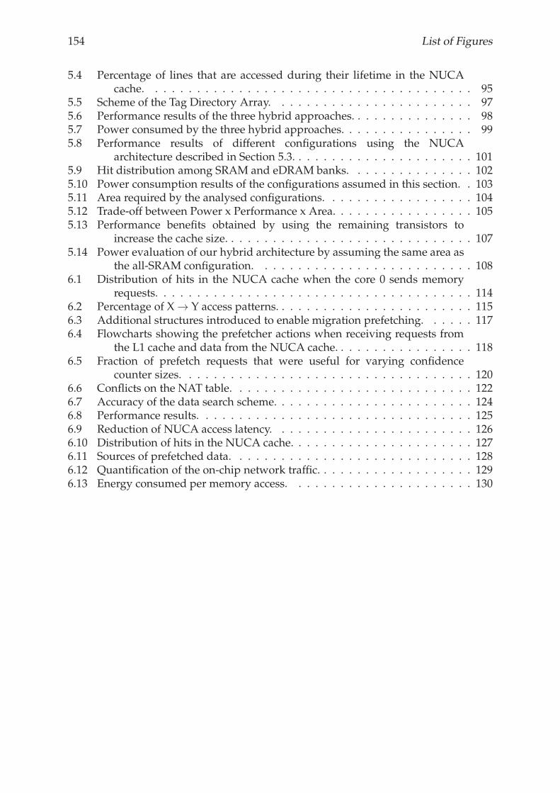
154 List of Figures
5.4 Percentage of lines that are accessed during their lifetime in the NUCAcache. . . . . . . . . . . . . . . . . . . . . . . . . . . . . . . . . . . . . . . 95
5.5 Scheme of the Tag Directory Array. . . . . . . . . . . . . . . . . . . . . . . . 975.6 Performance results of the three hybrid approaches. . . . . . . . . . . . . . . 985.7 Power consumed by the three hybrid approaches. . . . . . . . . . . . . . . . 995.8 Performance results of different configurations using the NUCA
architecture described in Section 5.3. . . . . . . . . . . . . . . . . . . . . . 1015.9 Hit distribution among SRAM and eDRAM banks. . . . . . . . . . . . . . . 1025.10 Power consumption results of the configurations assumed in this section. . 1035.11 Area required by the analysed configurations. . . . . . . . . . . . . . . . . . 1045.12 Trade-off between Power x Performance x Area. . . . . . . . . . . . . . . . . 1055.13 Performance benefits obtained by using the remaining transistors to
increase the cache size. . . . . . . . . . . . . . . . . . . . . . . . . . . . . . 1075.14 Power evaluation of our hybrid architecture by assuming the same area as
the all-SRAM configuration. . . . . . . . . . . . . . . . . . . . . . . . . . 1086.1 Distribution of hits in the NUCA cache when the core 0 sends memory
requests. . . . . . . . . . . . . . . . . . . . . . . . . . . . . . . . . . . . . . 1146.2 Percentage of X → Y access patterns. . . . . . . . . . . . . . . . . . . . . . . . 1156.3 Additional structures introduced to enable migration prefetching. . . . . . 1176.4 Flowcharts showing the prefetcher actions when receiving requests from
the L1 cache and data from the NUCA cache. . . . . . . . . . . . . . . . . 1186.5 Fraction of prefetch requests that were useful for varying confidence
counter sizes. . . . . . . . . . . . . . . . . . . . . . . . . . . . . . . . . . . 1206.6 Conflicts on the NAT table. . . . . . . . . . . . . . . . . . . . . . . . . . . . . 1226.7 Accuracy of the data search scheme. . . . . . . . . . . . . . . . . . . . . . . . 1246.8 Performance results. . . . . . . . . . . . . . . . . . . . . . . . . . . . . . . . . 1256.9 Reduction of NUCA access latency. . . . . . . . . . . . . . . . . . . . . . . . 1266.10 Distribution of hits in the NUCA cache. . . . . . . . . . . . . . . . . . . . . . 1276.11 Sources of prefetched data. . . . . . . . . . . . . . . . . . . . . . . . . . . . . 1286.12 Quantification of the on-chip network traffic. . . . . . . . . . . . . . . . . . . 1296.13 Energy consumed per memory access. . . . . . . . . . . . . . . . . . . . . . 130