Embed Size (px)
Citation preview
Making a Micrometer Vernier Sextant.
This article shows you how to build your own micrometer vernier sextant, also known as a 'Drum Sextant'. The actual accuracy of your sextant is up to you as you make it, but the precision is to 0.2 minutes of arc. The precision is more than adequate for navigation - this sextant is not a toy. Once you've finished making the sextant, assuming reasonable accuracy during manufacture, you will have a sextant at least as good as the one used by Captain Cook in the Endeavour when he sailed round the globe. Making this sturdy sextant will be an achievement that will give you satisfaction for years. That's enough of the advertising, I'll get on with it now.
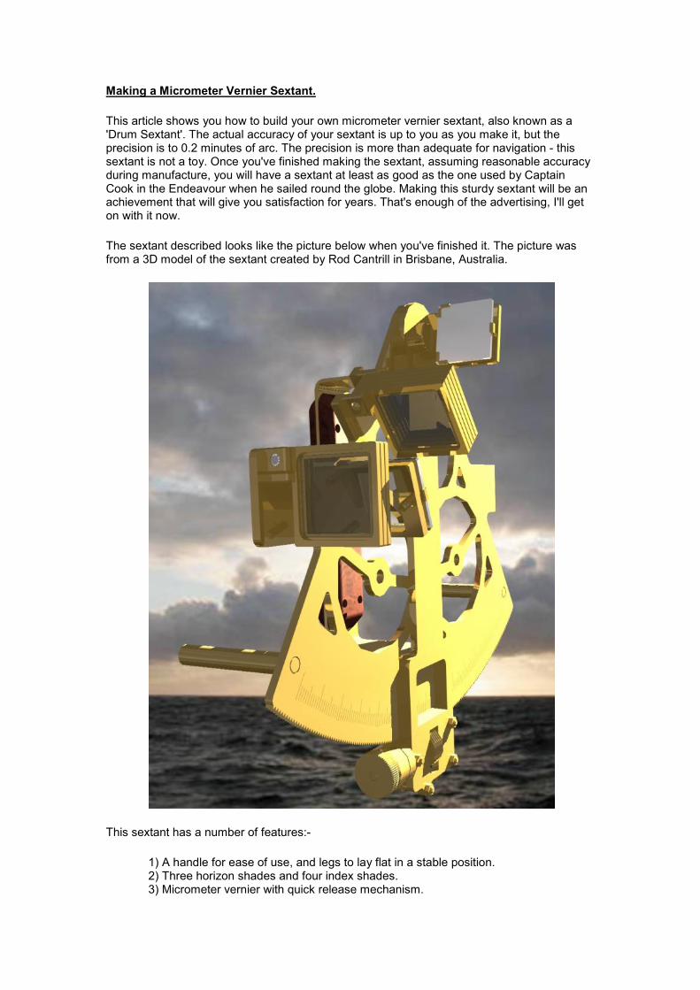
The sextant described looks like the picture below when you've finished it. The picture was from a 3D model of the sextant created by Rod Cantrill in Brisbane, Australia.
This sextant has a number of features:-
1) A handle for ease of use, and legs to lay flat in a stable position. 2) Three horizon shades and four index shades. 3) Micrometer vernier with quick release mechanism.

4) Stainless steel mirrors for corrosion resistance and reduced refraction error. 5) Sturdy brass design. 6) Index error may be completely corrected out. 7) Vernier precision to 0.2 arc seconds - greater precision if you wish! 8) The sextant costs the same as a very cheap plastic Ebbco sextant.
There is no telescope designed for this sextant, just somewhere to put one. I do not profess to be sufficiently knowledgeable in optics to be able to design one, so I leave this for you to design and implement. I recommend a 3x magnification, 30mm objective telescope. Commercial sextants have magnifications of 3x to 7x, while high quality cheap monoculars available in camera shops give a magnification of 8x and up. The choice is yours.
This article is split into a number of sections, as below:-
1) How the Sextant works 2) Skill level required. 3) Tools Required 4) Units used in this design 5) Raw Materials 6) Parts List 7) Making the Sextant 8) Special Tools 9) CAD drawings 10) Cutting Layout 11) And Finally.. (Legal stuff etc.) 12) Progress
1) How the Sextant Works
This sextant works in exactly the same way as all the older sextants. Light from the sun bounces off the index mirror, to the horizon mirror and then to the eye. The index arm is rotated until the bottom edge of the apparent image of the sun reflected by the horizon mirror is lined up with the horizon. The angle is then read off the sextant dial. (For a more full explanation of how a sextant works see http://www.tecepe.com.br/nav/sextantflash.html).
First off:-
What is a Micrometer Vernier Sextant, and how does it differ from a normal sextant?
Think of a sextant with a normal vernier to read the minutes of arc at the bottom of the index arm. Now cut gear teeth along the bottom of the arc of the sextant and add a threaded wheel like a worm wheel perpendicular to the teeth. This is the 'micrometer' section of the name. If the teeth are accurately cut, and the worm wheel is accurately threaded, you will be able to finely adjust the micrometer wheel and directly read off the minutes of arc from engravings on the micrometer handle. If a vernier is then added close to the micrometer wheel, it's comparatively easy to make a micrometer vernier.
How does the micrometer work?
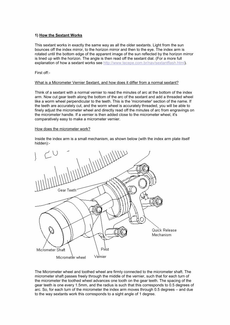
Inside the index arm is a small mechanism, as shown below (with the index arm plate itself hidden):-
The Micrometer wheel and toothed wheel are firmly connected to the micrometer shaft. The micrometer shaft passes freely through the middle of the vernier, such that for each turn of the micrometer the toothed wheel advances one tooth on the gear teeth. The spacing of the gear teeth is one every 1.5mm, and the radius is such that this corresponds to 0.5 degrees of arc. So, for each turn of the micrometer the index arm moves through 0.5 degrees – and due to the way sextants work this corresponds to a sight angle of 1 degree.
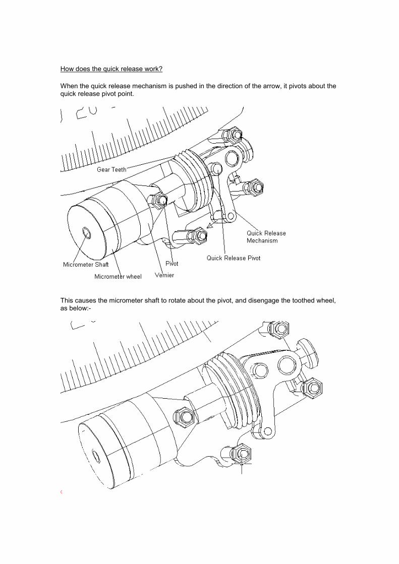
How does the quick release work?
When the quick release mechanism is pushed in the direction of the arrow, it pivots about the quick release pivot point.
This causes the micrometer shaft to rotate about the pivot, and disengage the toothed wheel, as below:-
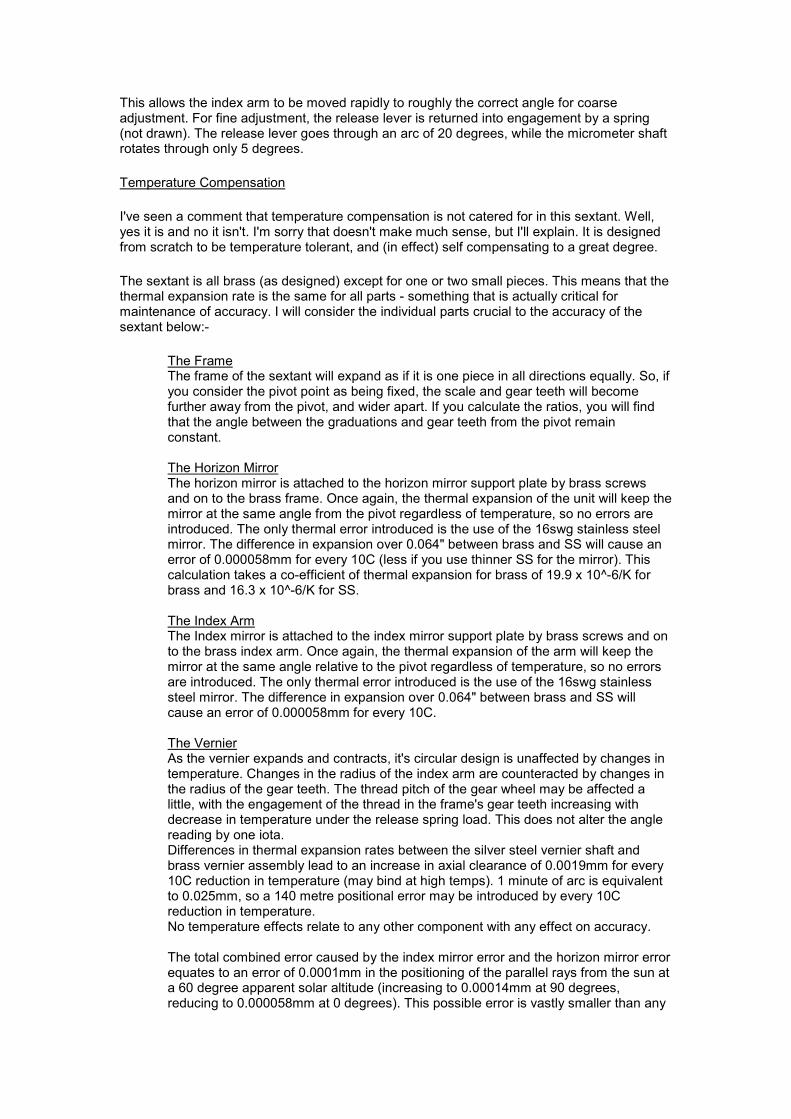
This allows the index arm to be moved rapidly to roughly the correct angle for coarse adjustment. For fine adjustment, the release lever is returned into engagement by a spring (not drawn). The release lever goes through an arc of 20 degrees, while the micrometer shaft rotates through only 5 degrees.
Temperature Compensation
I've seen a comment that temperature compensation is not catered for in this sextant. Well, yes it is and no it isn't. I'm sorry that doesn't make much sense, but I'll explain. It is designed from scratch to be temperature tolerant, and (in effect) self compensating to a great degree.
The sextant is all brass (as designed) except for one or two small pieces. This means that the thermal expansion rate is the same for all parts - something that is actually critical for maintenance of accuracy. I will consider the individual parts crucial to the accuracy of the sextant below:-
The FrameThe frame of the sextant will expand as if it is one piece in all directions equally. So, if you consider the pivot point as being fixed, the scale and gear teeth will become further away from the pivot, and wider apart. If you calculate the ratios, you will find that the angle between the graduations and gear teeth from the pivot remain constant. The Horizon MirrorThe horizon mirror is attached to the horizon mirror support plate by brass screws and on to the brass frame. Once again, the thermal expansion of the unit will keep the mirror at the same angle from the pivot regardless of temperature, so no errors are introduced. The only thermal error introduced is the use of the 16swg stainless steel mirror. The difference in expansion over 0.064" between brass and SS will cause an error of 0.000058mm for every 10C (less if you use thinner SS for the mirror). This calculation takes a co-efficient of thermal expansion for brass of 19.9 x 10^-6/K for brass and 16.3 x 10^-6/K for SS. The Index ArmThe Index mirror is attached to the index mirror support plate by brass screws and on to the brass index arm. Once again, the thermal expansion of the arm will keep the mirror at the same angle relative to the pivot regardless of temperature, so no errors are introduced. The only thermal error introduced is the use of the 16swg stainless steel mirror. The difference in expansion over 0.064" between brass and SS will cause an error of 0.000058mm for every 10C. The VernierAs the vernier expands and contracts, it's circular design is unaffected by changes in temperature. Changes in the radius of the index arm are counteracted by changes in the radius of the gear teeth. The thread pitch of the gear wheel may be affected a little, with the engagement of the thread in the frame's gear teeth increasing with decrease in temperature under the release spring load. This does not alter the angle reading by one iota. Differences in thermal expansion rates between the silver steel vernier shaft and brass vernier assembly lead to an increase in axial clearance of 0.0019mm for every 10C reduction in temperature (may bind at high temps). 1 minute of arc is equivalent to 0.025mm, so a 140 metre positional error may be introduced by every 10C reduction in temperature. No temperature effects relate to any other component with any effect on accuracy. The total combined error caused by the index mirror error and the horizon mirror error equates to an error of 0.0001mm in the positioning of the parallel rays from the sun at a 60 degree apparent solar altitude (increasing to 0.00014mm at 90 degrees, reducing to 0.000058mm at 0 degrees). This possible error is vastly smaller than any

machining accuracy you could hope for during manufacture of the sextant, so temperature considerations from this source may be ignored. If you are really concerned about temperature induced error, I suggest you take the following precautions:-
1) Make the vernier shaft from brass. 2) Zero the sextant in the climate that you expect to use it in. 3) Every time you take a reading, ensure that there is no end slop on the vernier shaft.
(The last precaution is for the terminally cautious..!) By taking these precautions any small sextant error due to temperature should have been eliminated.
And that's it. It's not too difficult is it?

2) Skill Level Required
This sextant is ideally tackled by a person with a reasonable level of mechanical ability and a fair level of metalworking experience. Having said that, given time and persistence, someone without any experience should be able to make it.
3) Tools Required
Here's the rub. To make an accurate metal sextant, you need accurate metalworking tools.
This sextant is designed to be made with a metalworking lathe, mill and rotary table. The actual lathe size can be as small as a watchmaker's lathe, allowing a bar of 25mm diameter to be turned. The milling is designed to be carried out with one 6mm diameter cutter and, optionally, one 3mm cutter. The smallest throat depth you need on the mill is about 25mm, so a very small mill could be used too. A bigger mill, obviously, would be better. You'll need a rotary table of at least 150mm (6") diameter, and a lump of timber/ ply to go under it.
The list of tools you need is:-
1) Lathe + lathe tools 2) Gears for lathe to cut a 1.5mm pitch thread OR M20x1.5 fine die. 3) Milling machine, milling head or adapter + 6mm end/slot mill. A 3mm mill is nice. 4) Rotary table 5) Gear cutter. I've drawn one up where it's used, so don't panic! 6) M3, M4 and M6 coarse taps, dies and tapping drills. HSS is preferred, as they tend to cut better threads. 7) Engraving cutters. I've drawn up two different ones that you can make. 8) 3.9 & 5.9mm dia drills and 4/6mm reamers. I've drawn up home-made reamers that are suitable. 9) A range of files, some needle and some normal sized. 10) Hacksaw & piercing saw. 11) A range of drills. 2, 4, 6 and 7mm being the minimum, a 14mm drill can be used if you've got one handy. 12) Glass cutter. 13) Metal Polish & Lacquer. 14) Range of metalworking layout & marking tools. 15) Blow Lamp/ Blow Torch powerful enough to melt silver solder. 16) Medium or fine straight knurl. 17) 6mm diameter HSS toolbit, or hardened Silver Steel. 18) A face mill would be nice, but the end mill and/or filing will enable the job to be done without one.
What lathe & mill do I use?
A combined mill/lathe with a 300mm swing over the bed and 175mm mill throat capacity. (If you're interested it's a Warco WMT300.) My rotary table is 6" in diameter with an MT2 central taper for which I've made a number of fixtures to help me machine the sextant. To be honest, the lathe is almost too big for this little sextant. Holding a 3mm diameter bar in a 127mm (5") chuck is ridiculous. I have only one milling collet, hence the use of 6mm shanks wherever possible.
If you don't have a lathe or mill, and can't afford one, but do have the time to make a machine shop from scrap materials then I'd suggest that you look at the series of books at http://www.lindsaybks.com/dgjp/djgbk/series/index.html. It wasn't the way I went, but I have made a furnace similar to the one shown in the first book. A nice bit of kit really, and surprisingly easy to use.

4) A note on the units used for this design.
I have designed this sextant in the UK, where units are in a bit of a muddle. Most full size engineering is conducted in millimetres. The drawings are in millimetres (unless stated otherwise). However most of the general population use inches for rough dimensions, and model engineering suppliers are well and truly wedded to inches as their preferred dimensions. Unfortunately, the only people prepared to sell materials in the small quantities for this sextant are model engineering suppliers. That's why you will see some utterly ridiculous thicknesses specified (eg the frame is 3.2512mm, because that's the metric equivalent of 10swg plate).
If you wish to work in inches, remember to divide the millimetre dimension by 25.4. In most cases, you can substitute the nearest sensible inch dimension for the metric one. However, DO NOT, UNDER ANY CIRCUMSTANCES CHANGE THE TOOTH PITCH OR RADIUS OF THE GEAR TEETH. Sorry I shouted, but I must make it plain that the tooth pitch and radius is VITAL to the operation of this sextant. If you wish to use a different thread pitch you'll need to redesign the sextant yourself. The thread and radius of the sextant body are inextricably linked - it must be sized so that:-
Radius = 360 x Thread Pitch / 3.141592654
Note:- If working in inches the pitch is the distance between crests NOT the number of crests per inch - so for 20 TPI the pitch is 0.05".
5) Raw Materials
Brass
The majority of raw materials used within this sextant are brass of one sort or another.
For the main frame of the sextant, I have specified Compo Brass. This is a free machining variant used by engravers. As the graduations on the sextant are engraved, I chose the type preferred by engravers. In the UK, it's given the designation CZ121, which will be of no use to anyone sourcing it outside the UK whatsoever.. [Sorry!] Compo brass appears to be about 20% more expensive than normal brass.
If you wish to use aluminium, then go ahead. As far as I can tell 6082-T6 is stronger and it is certainly lighter than brass – but it will show local damage more easily and will need to be anodised for marine use. The best alloy for marine use is 5086 (won't need anodising except to keep it shiny), but I fear that you are unlikely to get it in small quantities. 5086 in the O condition is of similar strength to annealed brass, but it is softer, so will mark more easily. In the hardened (H8) condition it is still workable, is almost as strong as 6082-T6, and could be used.
If aluminium is OK for you, who am I to gainsay your choice? There are many very expensive aluminium sextants (the Astra IIIB, Tamaya Spica & Jupiter to name but three), so you'll be in good company. However, to maintain the accuracy of the sextant over a wide range of temperatures, please use the aluminium for as much of the sextant as you can. This way most of the self compensating temperature effects will be maintained.
Silver Steel
I have specified silver steel in a few places. In North America, the equivalent is called 'drill rod' – I don't know about elsewhere. For the micrometer shaft I have simply specified it because I think the strength and stiffness of steel is required, and didn't want to buy a stainless steel rod as it's not dual use (for reamers..). The use of brass in the vernier shaft would totally eliminate the biggest potential source to temperature induced errors in the sextant. You can experiment yourself at very little expense if you wish! In the case of the locating pegs and shade pivots I specified silver steel as it has a close manufacturing tolerance (can be used with no further machining) and it can be soldered, while SS can't. Brass would be suitable here – but in the UK it isn't readily available in metric sizes.
Glass Shades.
Here I had no choice at all. I was limited by what was available, and I think you will be too. My shades (when they finally arrived after 6 weeks wait) turned out to be 2.5mm thick No. 3 welding shades, which meant that I only had room for two horizon shades without a slight redesign - not a great problem as many 'real' sextants only have two shades here too.
Timber.
You don't need timber at all. I just wanted to have a nice traditional hardwood handle. A turned brass handle would be good too – and softwood would be equally good.
Mirrors
The mirrors I have specified are stainless steel. If you can, try to get electro-polished stainless steel. This will save you a huge amount of time when it comes to polishing the mirrors as ordinary SS sheet has numerous tiny ripples making for a blurred image (been there, it took me 6 hours of polishing with a bench grinder to get an acceptable finish - not much fun!). If

you can, choose a 316 type stainless steel. The type I bought was 304S11 (UK designation for a low carbon sheet), and it has a slightly less 'silvery' luster to the reflections than you get from 316 stainless. Not of vital importance, but worth trying to get. If you wish to, you could use surface mirrored glass (to avoid refraction errors), or even a semi-transparent mirror for the horizon mirror. If you choose to get one of these, it will probably take some searching to find a source. I have to thank Redgie Joy for a link to http://www.sciplus.com/singleItem.cfm?terms=9528&cartLogFrom=Search where it appears that such mirrors may be available.
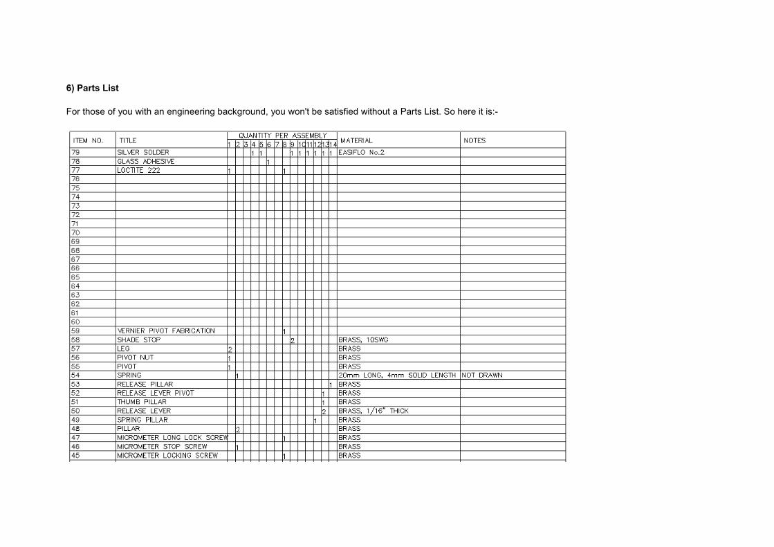
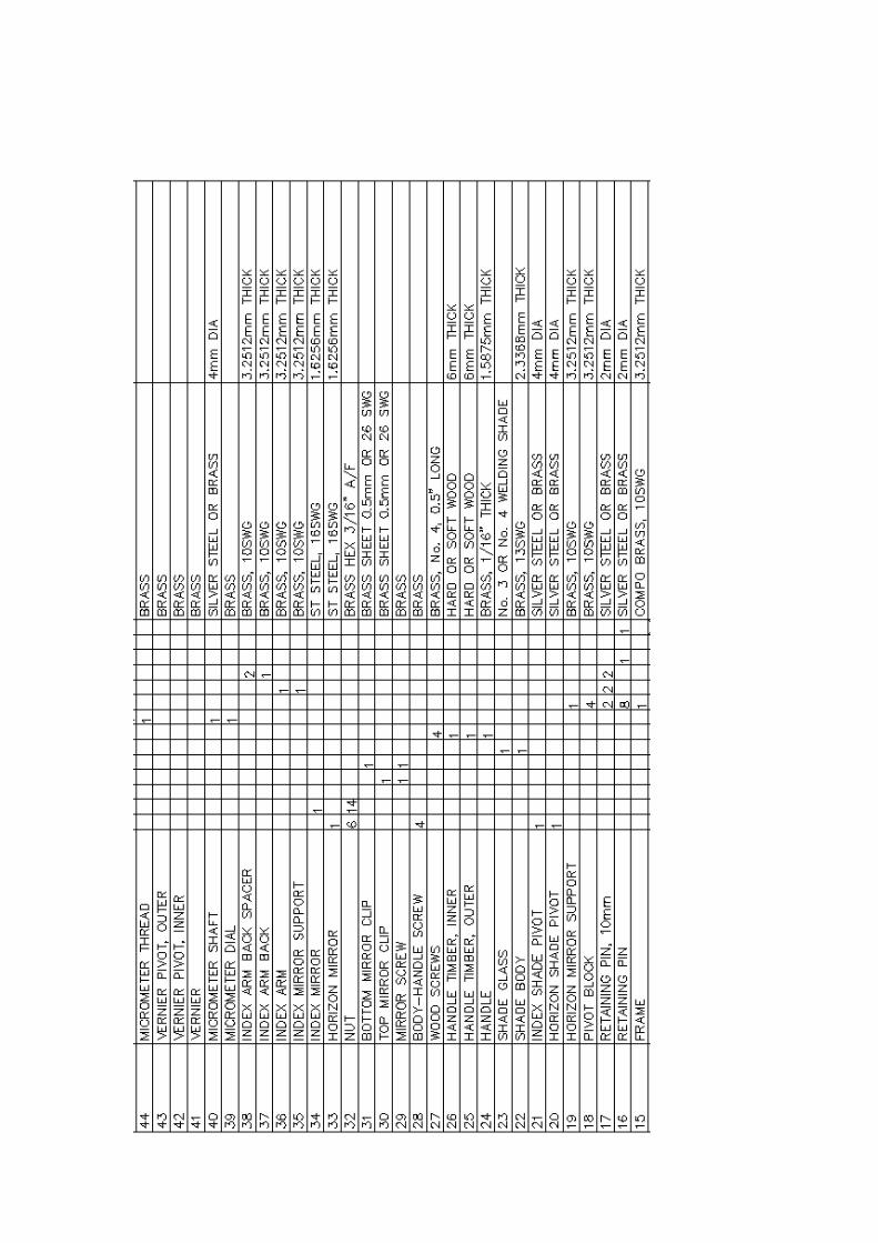
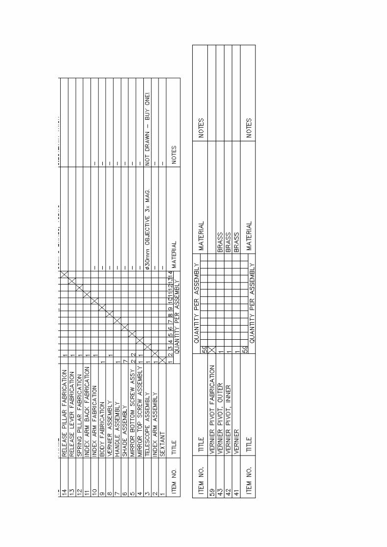
6) Parts List
For those of you with an engineering background, you won't be satisfied without a Parts List. So here it is:-
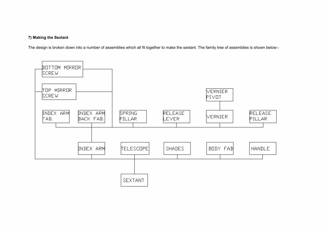
7) Making the Sextant
The design is broken down into a number of assemblies which all fit together to make the sextant. The family tree of assemblies is shown below:-
The following notes apply to the drawings:-
In the drawings I have specified Silver Solder (melting temperature 660C or above). On reflection, I was probably over specifying this. Ordinary soft solder (melting temp around 170C) is strong enough, has adequate corrosion resistance, is more readily available, and is cheaper. Use it, if you wish, with my blessing.
A few words of advice.. Many of the parts are TINY. I suggest you avoid sneezing when handling them, otherwise you will never see them again! Yes, I have done that. I completely lost one of Item 31, Bottom Mirror Clip, much to my irritation! Parting off small items on the lathe can also lead to low flying brass. A loose cloth tied up behind the lathe can catch many pieces that would otherwise be lost for ever. When you've completed the parts, it would be a good idea to keep them safe in a pot until they are needed. I use an old take away food container, which is big enough to hold all the parts except the frame and index arm.
I think it's best to start with the simpler assemblies and work up from there. If nothing else, it'll help build confidence for the more complex parts later on. As a result, the design is broken down into the assemblies, as listed below:-
7.1) Mirror Top Screw Assembly (Item 4) 7.2) Mirror Bottom Screw Assembly (Item 5) 7.3) Release Pillar Fabrication (Item 14) 7.4) Spring Pillar Fabrication (Item 12) 7.5) Release Lever Fabrication (Item 13)

7.6) Shade Assembly (Item 6) 7.7) Handle Assembly (Item 7) 7.8) Vernier Pivot Fabrication (Item 59) 7.9) Vernier Assembly (Item 8) 7.10) Index Arm Fabrication (Item 10) 7.11) Index Arm Back Fabrication (Item 11) 7.12) Index Arm Assembly (Item 2) 7.13) Body Fabrication (Item 9) 7.14) Telescope (Item 3) 7.15) Sextant Assembly (Item 1)
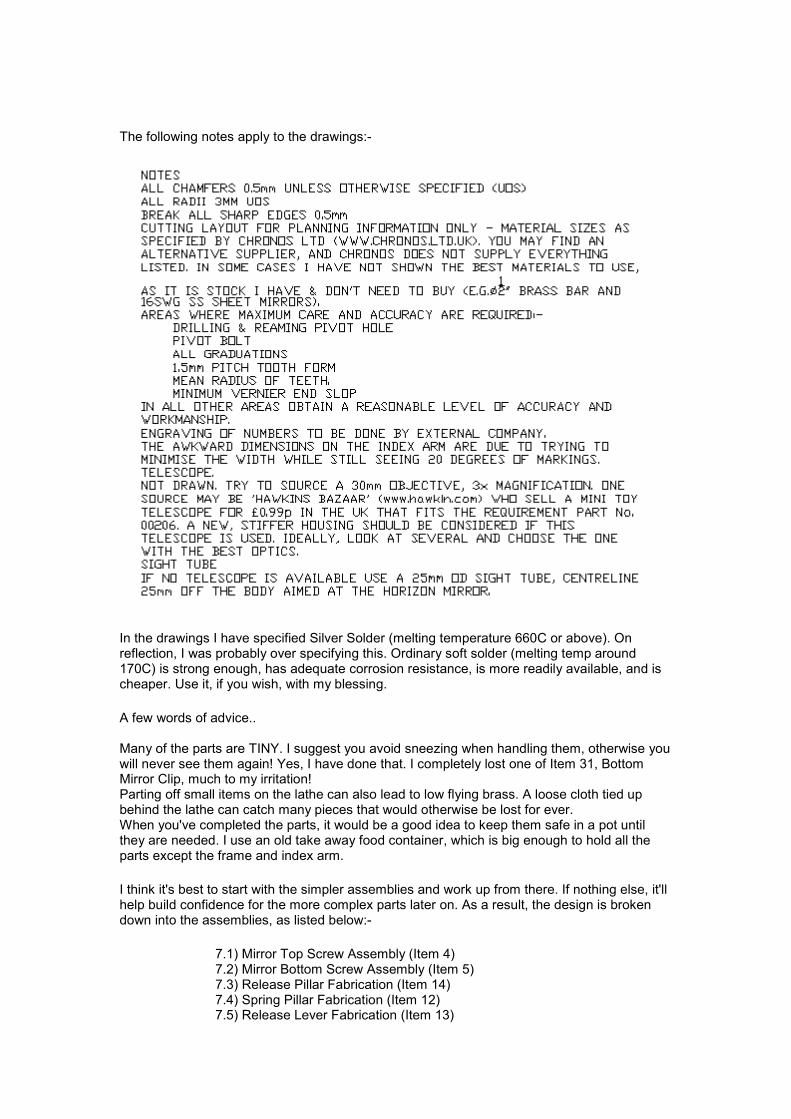
7.1) Item 4, Mirror Top Screw Assembly
Two top mirror assemblies are needed, looking as below:-
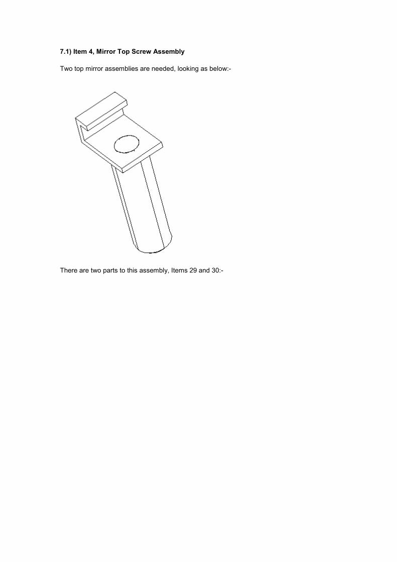
There are two parts to this assembly, Items 29 and 30:-
It's best to make item 30 first. Then turn down the 2mm dia spigot on item 29, reducing the diameter until it just fits in the hole drilled in item 30. When making Item 29, I actually made the 10.17 dimension a rather easier 10.5mm.
Once drilled, solder the two together using silver solder (item 79)
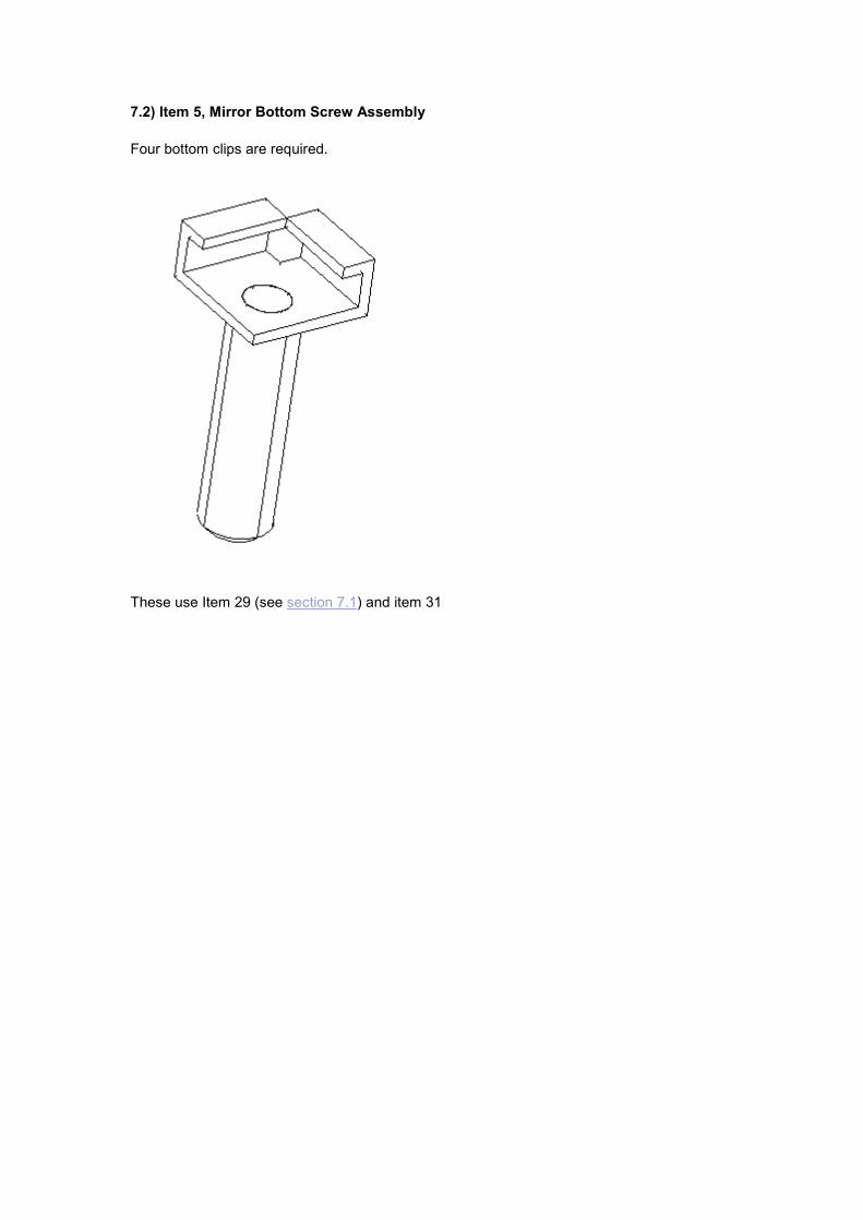
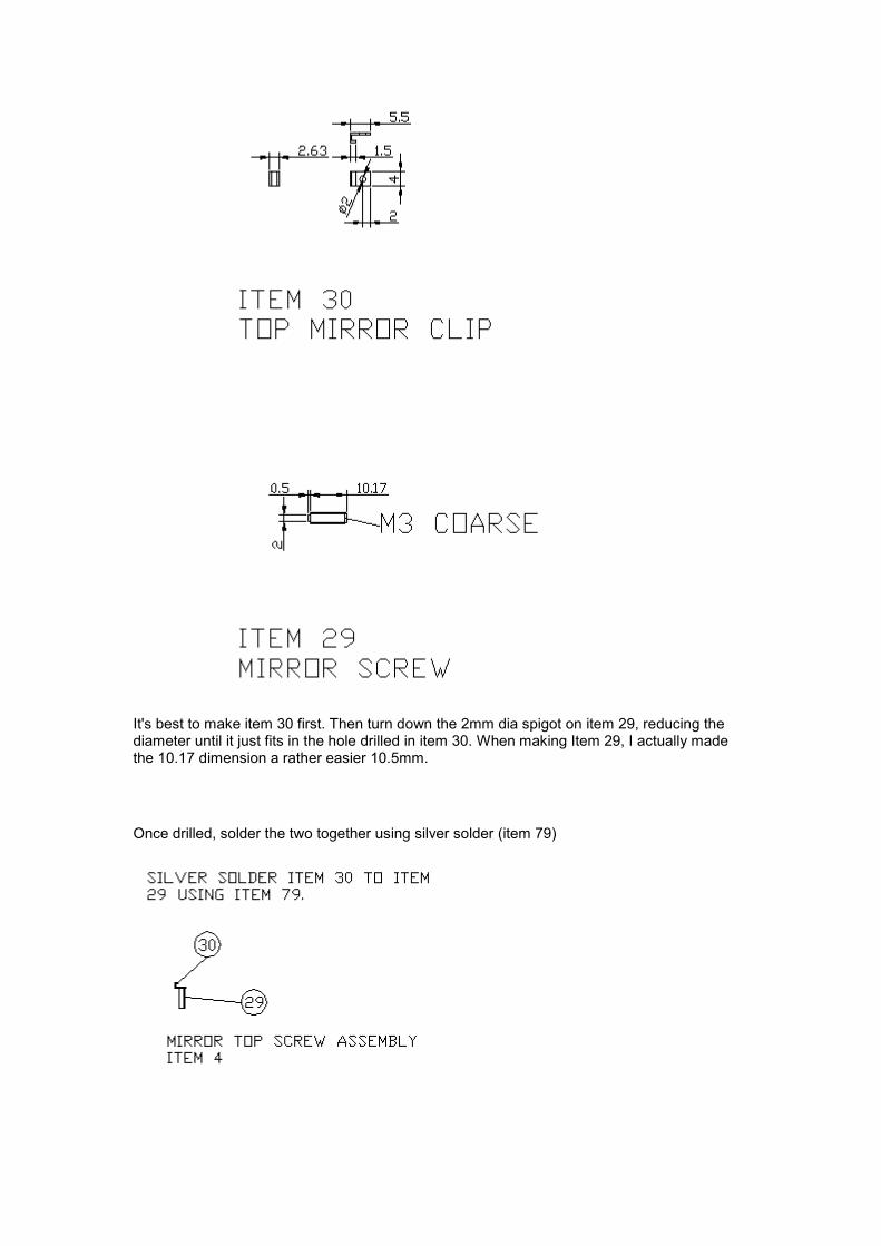
7.2) Item 5, Mirror Bottom Screw Assembly
Four bottom clips are required.
These use Item 29 (see section 7.1) and item 31
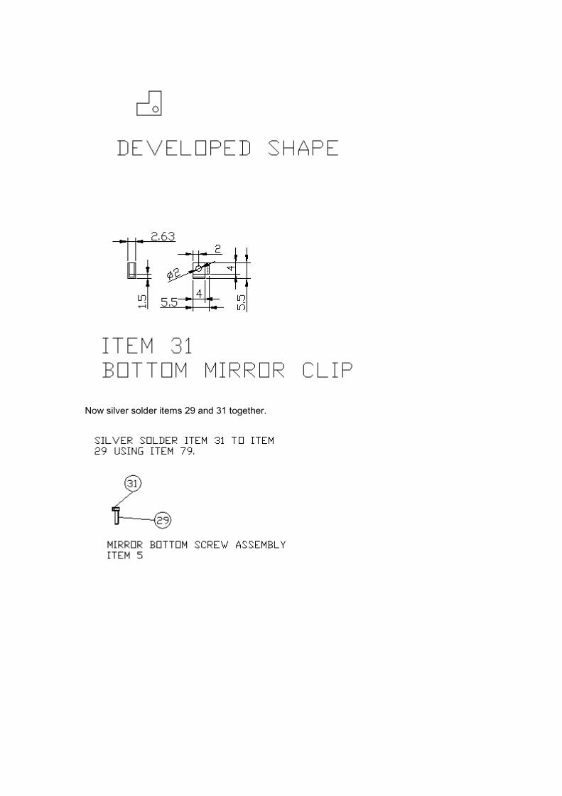
Now silver solder items 29 and 31 together.
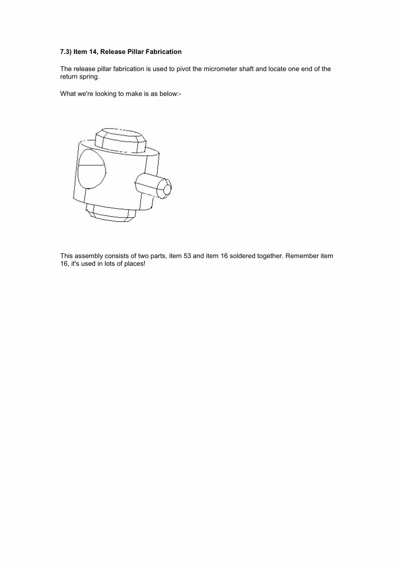
7.3) Item 14, Release Pillar Fabrication
The release pillar fabrication is used to pivot the micrometer shaft and locate one end of the return spring.
What we're looking to make is as below:-
This assembly consists of two parts, item 53 and item 16 soldered together. Remember item 16, it's used in lots of places!
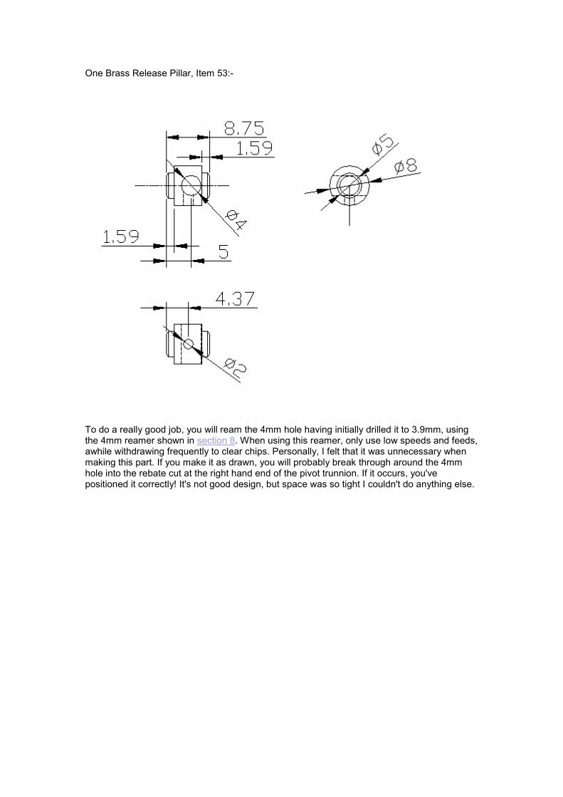
One Brass Release Pillar, Item 53:-
To do a really good job, you will ream the 4mm hole having initially drilled it to 3.9mm, using the 4mm reamer shown in section 8. When using this reamer, only use low speeds and feeds, awhile withdrawing frequently to clear chips. Personally, I felt that it was unnecessary when making this part. If you make it as drawn, you will probably break through around the 4mm hole into the rebate cut at the right hand end of the pivot trunnion. If it occurs, you've positioned it correctly! It's not good design, but space was so tight I couldn't do anything else.
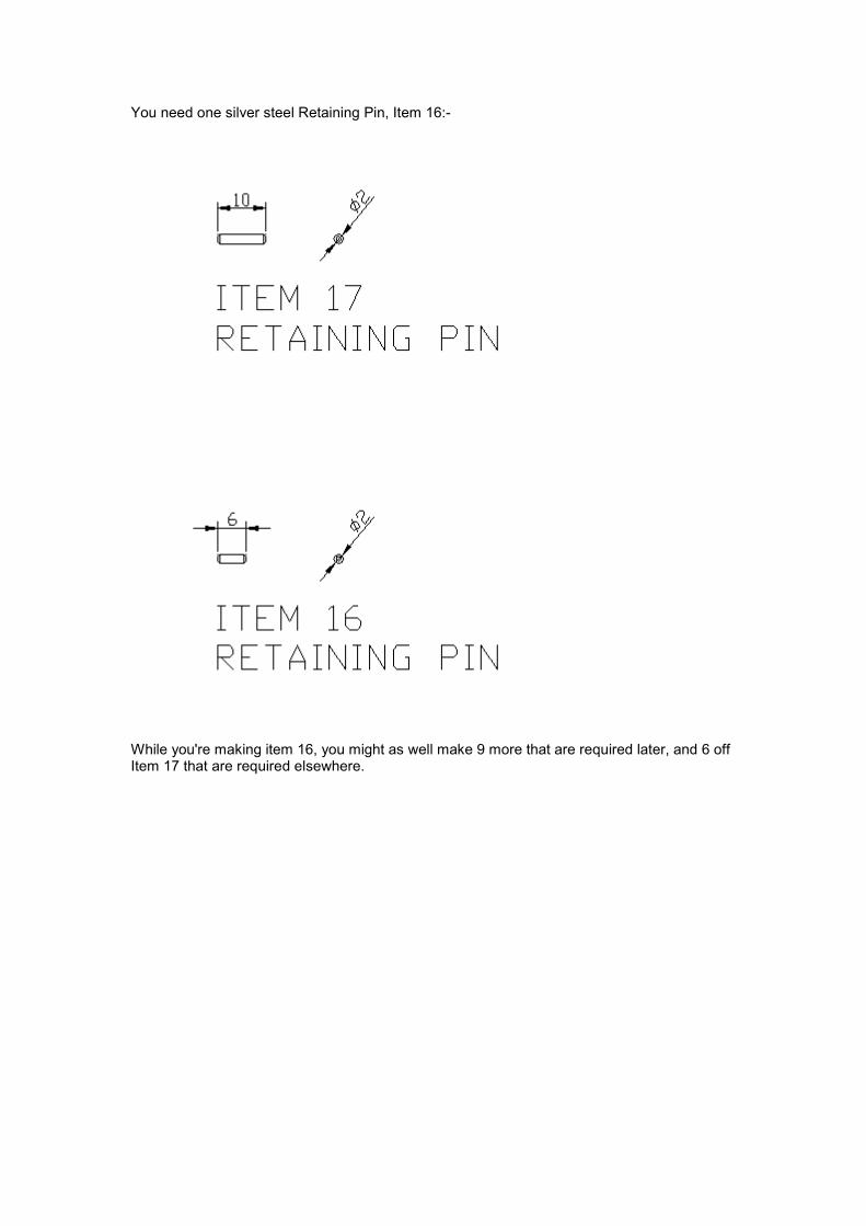
You need one silver steel Retaining Pin, Item 16:-
While you're making item 16, you might as well make 9 more that are required later, and 6 off Item 17 that are required elsewhere.
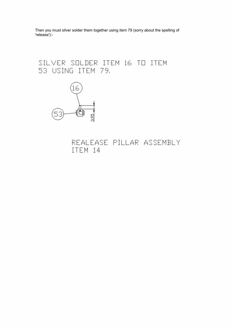
Then you must silver solder them together using item 79 (sorry about the spelling of 'release'):-
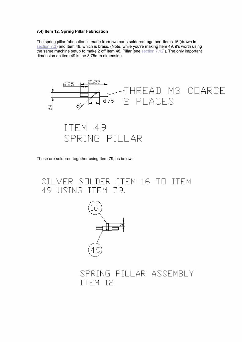
7.4) Item 12, Spring Pillar Fabrication
The spring pillar fabrication is made from two parts soldered together, Items 16 (drawn in section 7.3) and Item 49, which is brass. (Note, while you're making Item 49, it's worth using the same machine setup to make 2 off Item 48, Pillar [see section 7.12]). The only important dimension on item 49 is the 8.75mm dimension.
These are soldered together using Item 79, as below:-
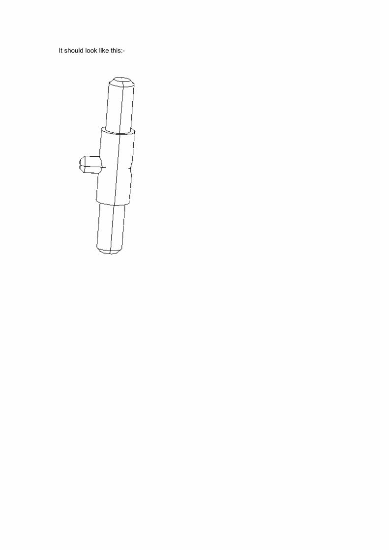
It should look like this:-
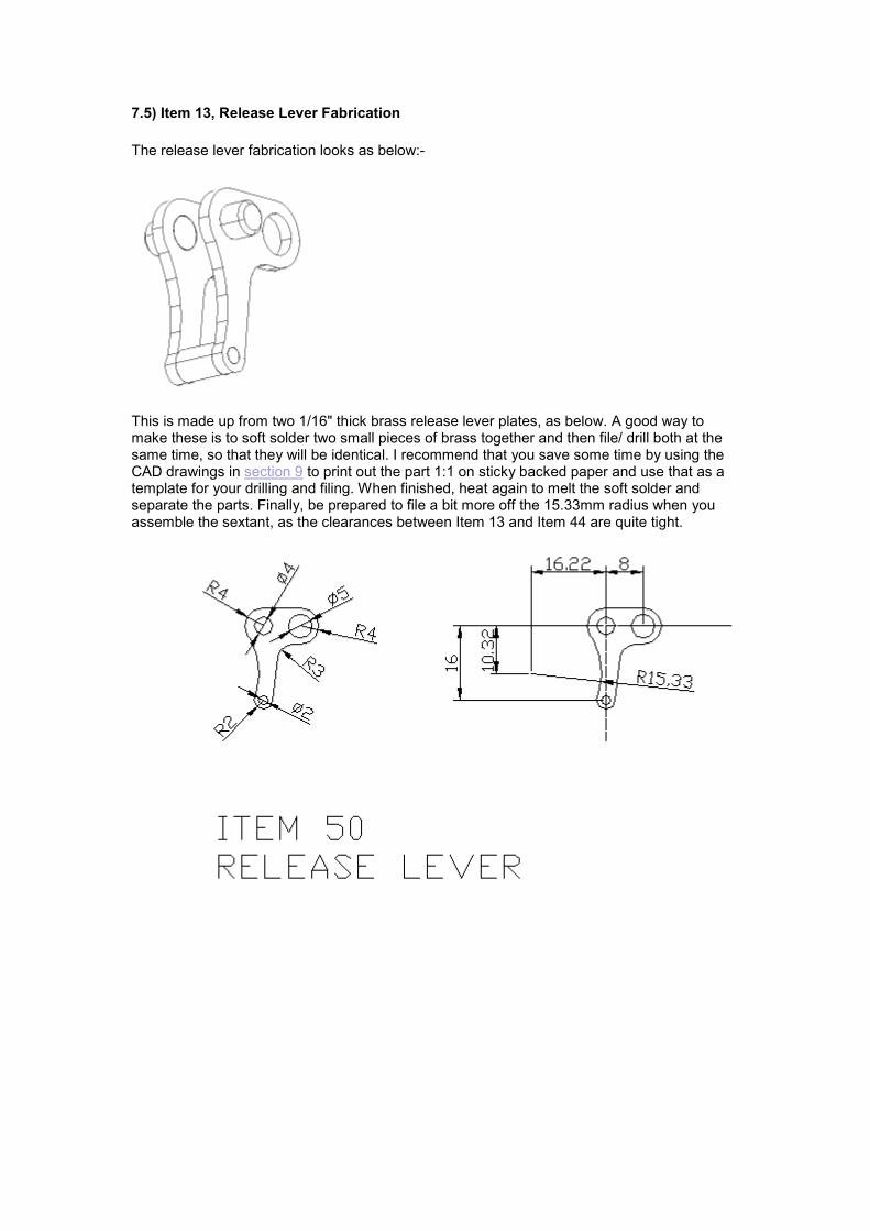
7.5) Item 13, Release Lever Fabrication
The release lever fabrication looks as below:-
This is made up from two 1/16" thick brass release lever plates, as below. A good way to make these is to soft solder two small pieces of brass together and then file/ drill both at the same time, so that they will be identical. I recommend that you save some time by using the CAD drawings in section 9 to print out the part 1:1 on sticky backed paper and use that as a template for your drilling and filing. When finished, heat again to melt the soft solder and separate the parts. Finally, be prepared to file a bit more off the 15.33mm radius when you assemble the sextant, as the clearances between Item 13 and Item 44 are quite tight.
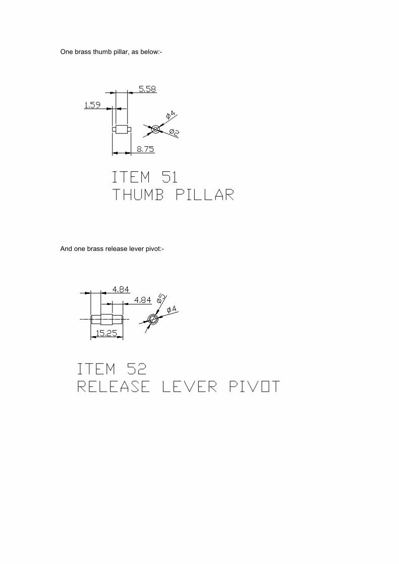
One brass thumb pillar, as below:-
And one brass release lever pivot:-
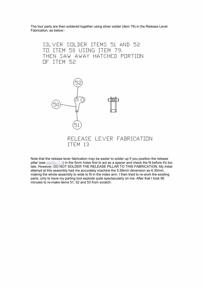
The four parts are then soldered together using silver solder (item 79) in the Release Lever Fabrication, as below:-
Note that the release lever fabrication may be easier to solder up if you position the release pillar (see section 7.3) in the 5mm holes first to act as a spacer and check the fit before it's too late. However, DO NOT SOLDER THE RELEASE PILLAR TO THIS FABRICATION. My initial attempt at this assembly had me accurately machine the 5.58mm dimension as 6.30mm, making the whole assembly to wide to fit in the index arm. I then tried to re-work the existing parts, only to have my parting tool explode quite spectacularly on me. After that I took 90 minutes to re-make items 51, 52 and 53 from scratch.
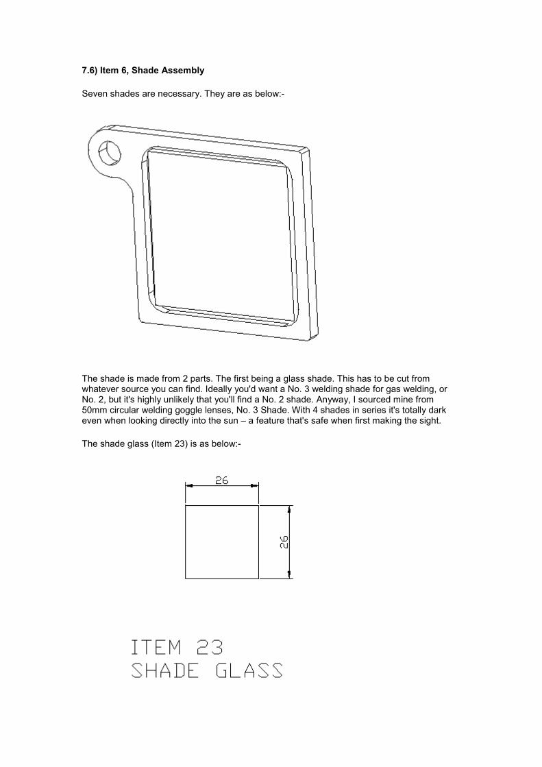
7.6) Item 6, Shade Assembly
Seven shades are necessary. They are as below:-
The shade is made from 2 parts. The first being a glass shade. This has to be cut from whatever source you can find. Ideally you'd want a No. 3 welding shade for gas welding, or No. 2, but it's highly unlikely that you'll find a No. 2 shade. Anyway, I sourced mine from 50mm circular welding goggle lenses, No. 3 Shade. With 4 shades in series it's totally dark even when looking directly into the sun – a feature that's safe when first making the sight.
The shade glass (Item 23) is as below:-
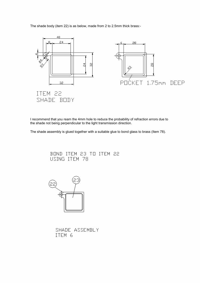
The shade body (item 22) is as below, made from 2 to 2.5mm thick brass:-
I recommend that you ream the 4mm hole to reduce the probability of refraction errors due to the shade not being perpendicular to the light transmission direction.
The shade assembly is glued together with a suitable glue to bond glass to brass (Item 78).

When I designed the sextant I measured up my No. 10 welding lens, and found it was 1.75mm thick - the pocket depth on item 22. This seemed fine, until I found that the No. 3 welding shade I ordered came to 2.5mm thick. This is causing me some problems, as I don't have the equipment to grind glass back by 0.75mm. This means that I would have to bond the shade glass in so that it stands proud of the frame by 0.75mm. This extra width to the shade means that I would have to reduce the number of horizon shades from 3 to 2 and the number of index shades from 4 to 3, as there is no room for the number designed. It's beginning to sound like time for a small redesign.
On further reflection, I will change the design and use the thicker brass that is used for the sextant frame. This is 3.2515mm thick, but the change means that I'll have to change the detail around the shades. This will affect the frame, shade body, shade pivot bars and shade stops (items 15, 20-22 and 58). There is sufficient spare material in a 12" square piece of brass used for the sextant frame to be able to do this without any extra cost. Which means I have one piece of 6" square x 12 swg brass spare now. If you want a copy of the revised drawing, contact me at the e-mail address specified in section 11. I'm leaving the original design up until I finish the sextant, but will continue to update the text with comments if I have them.
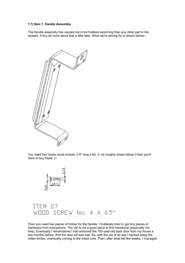
7.7) Item 7, Handle Assembly
The handle assembly has caused me more fruitless searching than any other part in the sextant. A tiny bit more about that a little later. What we're aiming for is shown below:-
You need four brass wood screws, 0.5" long x No. 4, as roughly drawn below (I fear you'll have to buy these..):-
Then you need two pieces of timber for the handle. I fruitlessly tried to get tiny pieces of hardwood from everywhere. The UK is not a good place to find hardwood (especially not free). Eventually I remembered I had removed the 105-year-old back door from my house a few months before. And the door sill was oak. So, with the aid of an axe I hacked away the rotten timber, eventually coming to the intact core. Then, after what felt like weeks, I managed
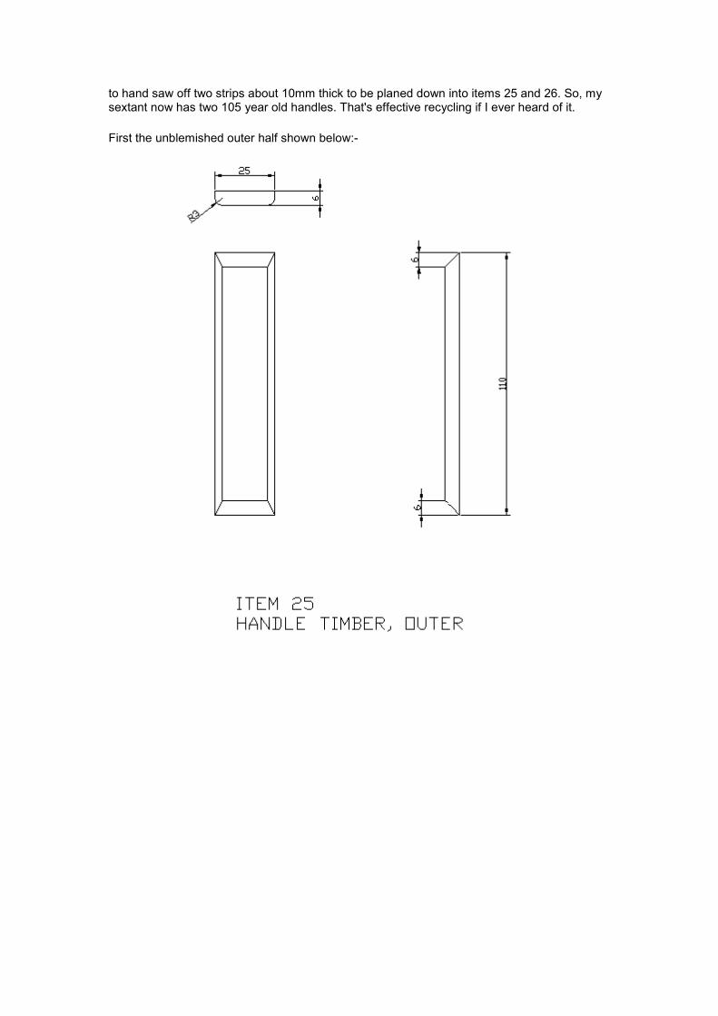
to hand saw off two strips about 10mm thick to be planed down into items 25 and 26. So, my sextant now has two 105 year old handles. That's effective recycling if I ever heard of it.
First the unblemished outer half shown below:-
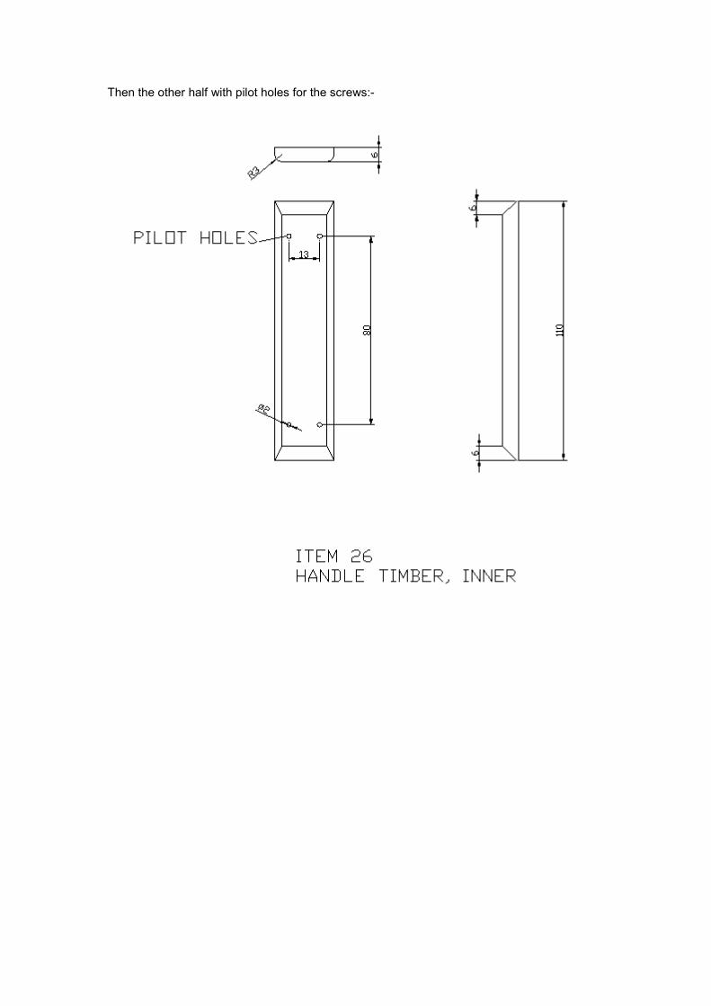
Then the other half with pilot holes for the screws:-
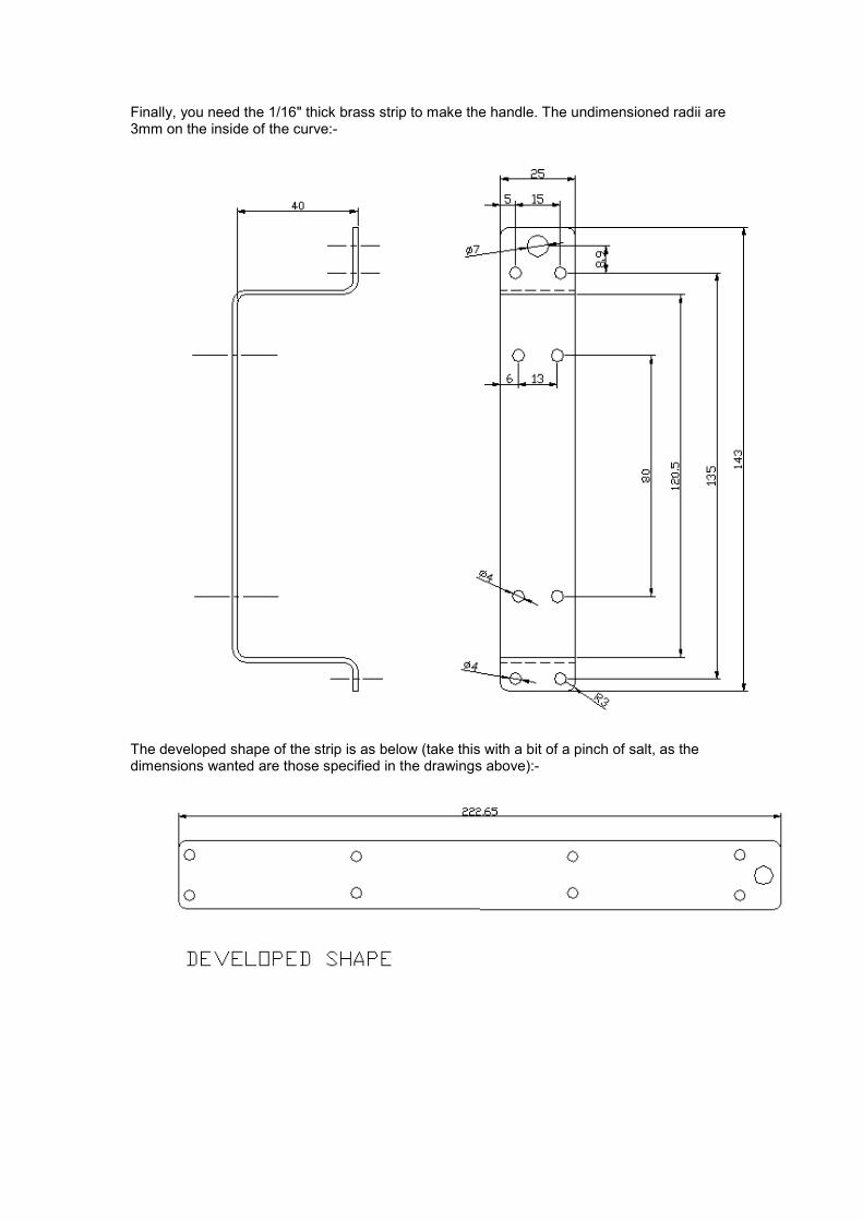
Finally, you need the 1/16" thick brass strip to make the handle. The undimensioned radii are 3mm on the inside of the curve:-
The developed shape of the strip is as below (take this with a bit of a pinch of salt, as the dimensions wanted are those specified in the drawings above):-
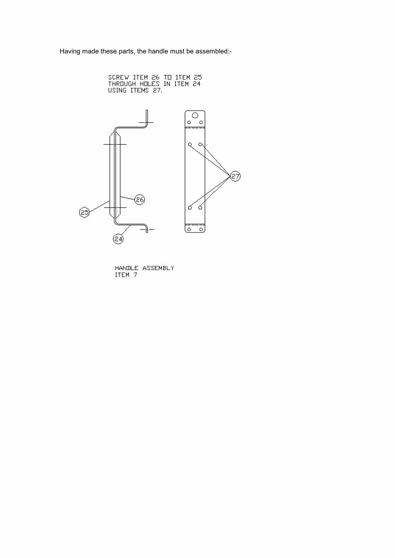
Having made these parts, the handle must be assembled:-
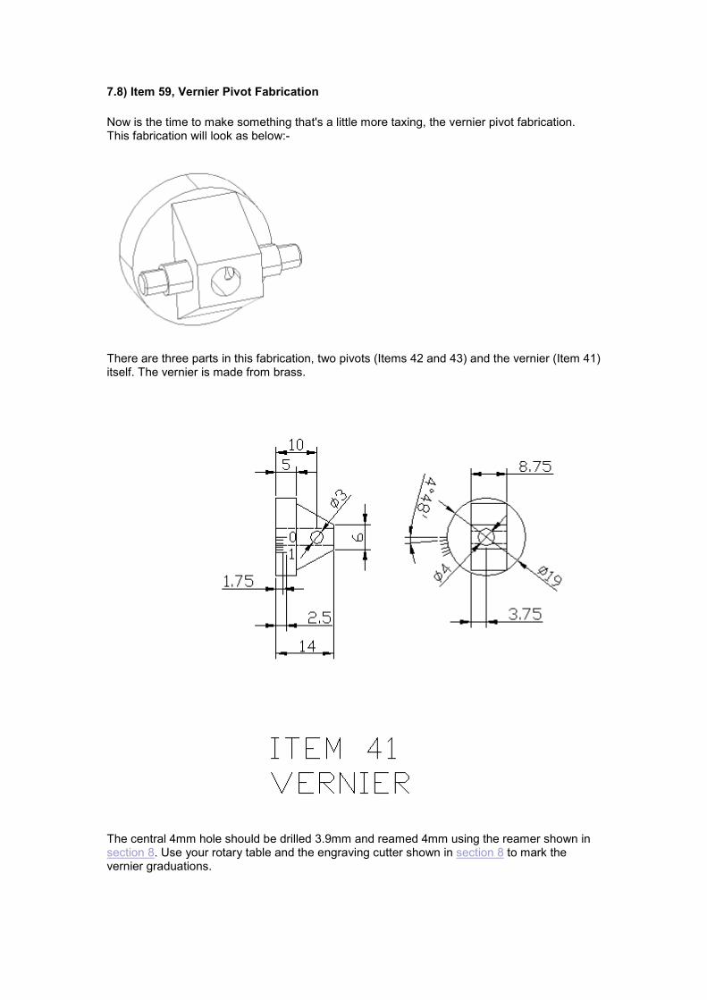
7.8) Item 59, Vernier Pivot Fabrication
Now is the time to make something that's a little more taxing, the vernier pivot fabrication. This fabrication will look as below:-
There are three parts in this fabrication, two pivots (Items 42 and 43) and the vernier (Item 41) itself. The vernier is made from brass.
The central 4mm hole should be drilled 3.9mm and reamed 4mm using the reamer shown in section 8. Use your rotary table and the engraving cutter shown in section 8 to mark the vernier graduations.
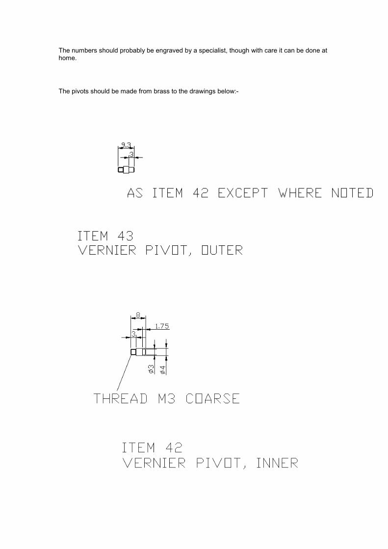
The numbers should probably be engraved by a specialist, though with care it can be done at home.
The pivots should be made from brass to the drawings below:-
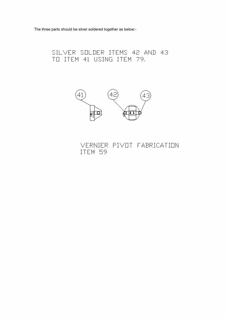
The three parts should be silver soldered together as below:-
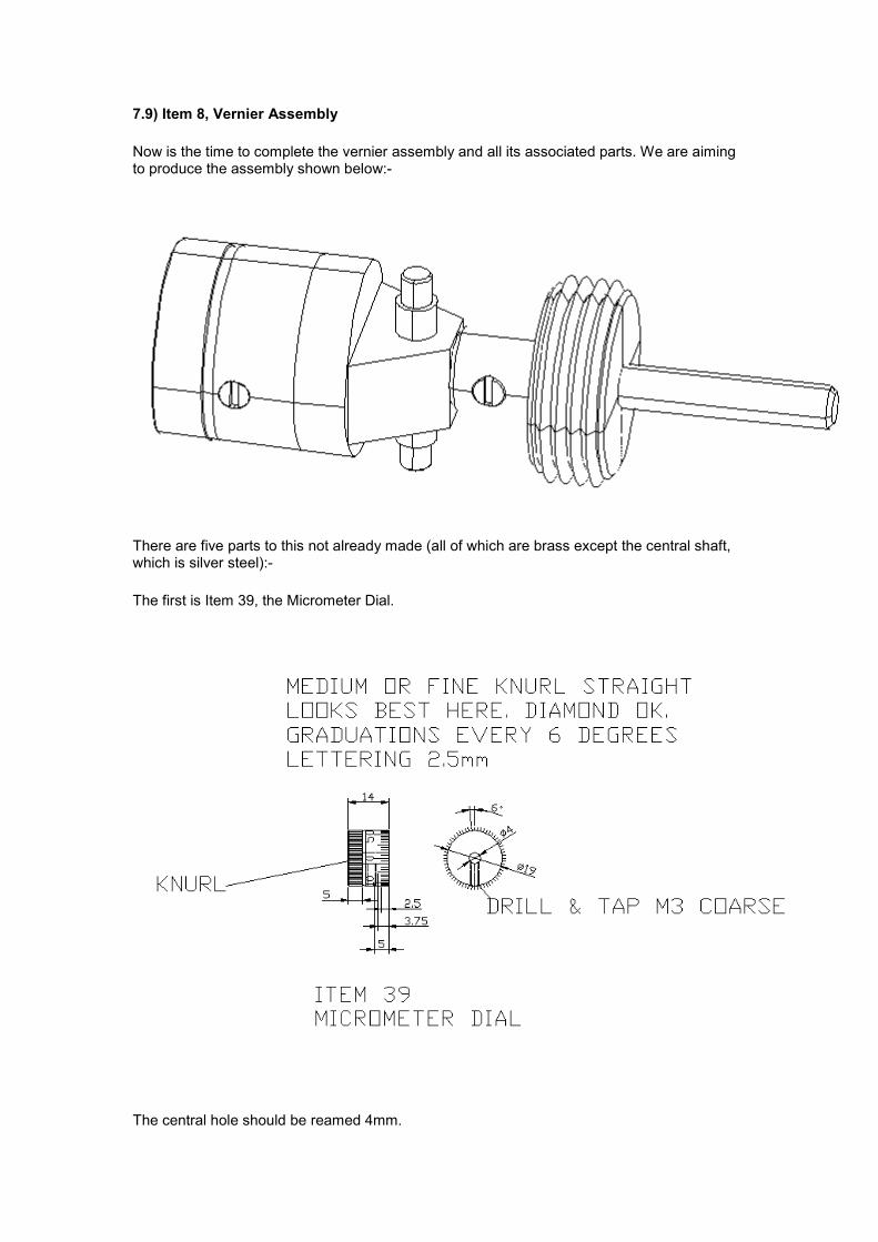
7.9) Item 8, Vernier Assembly
Now is the time to complete the vernier assembly and all its associated parts. We are aiming to produce the assembly shown below:-
There are five parts to this not already made (all of which are brass except the central shaft, which is silver steel):-
The first is Item 39, the Micrometer Dial.
The central hole should be reamed 4mm.
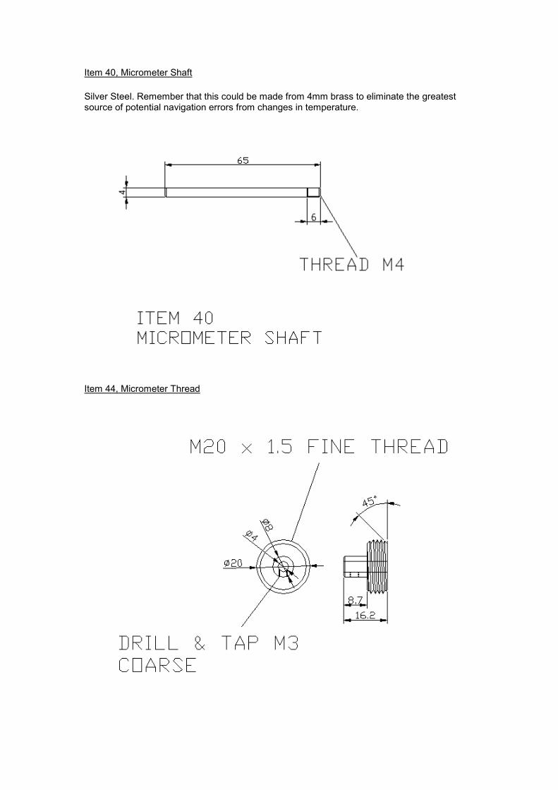
Item 40, Micrometer Shaft
Silver Steel. Remember that this could be made from 4mm brass to eliminate the greatest source of potential navigation errors from changes in temperature.
Item 44, Micrometer Thread
This part can be threaded using either a single point tool on the lathe or by using an M20 x 1.5 fine die. The former choice takes longer, but will be better in this application as you have more control over the thread form. Added to which, if you haven't got a die, it'll be an expensive purchase to do just one job. The central hole should be reamed 4mm.
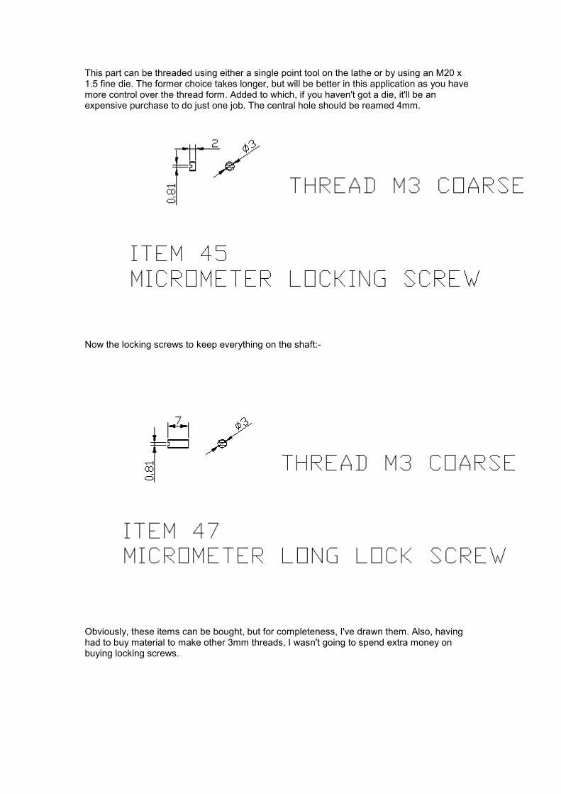
Now the locking screws to keep everything on the shaft:-
Obviously, these items can be bought, but for completeness, I've drawn them. Also, having had to buy material to make other 3mm threads, I wasn't going to spend extra money on buying locking screws.
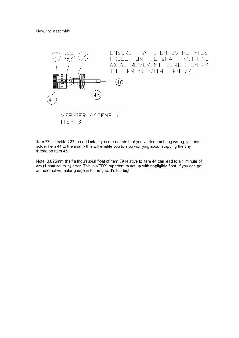
Now, the assembly
Item 77 is Loctite 222 thread lock. If you are certain that you've done nothing wrong, you can solder Item 44 to the shaft - this will enable you to stop worrying about stripping the tiny thread on Item 45.
Note: 0.025mm (half a thou') axial float of item 39 relative to item 44 can lead to a 1 minute of arc (1 nautical mile) error. This is VERY important to set up with negligible float. If you can get an automotive feeler gauge in to the gap, it's too big!
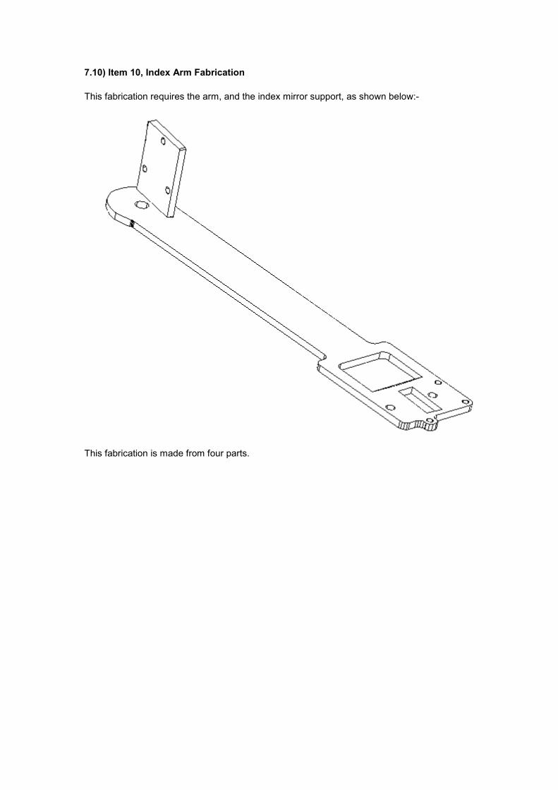
7.10) Item 10, Index Arm Fabrication
This fabrication requires the arm, and the index mirror support, as shown below:-
This fabrication is made from four parts.
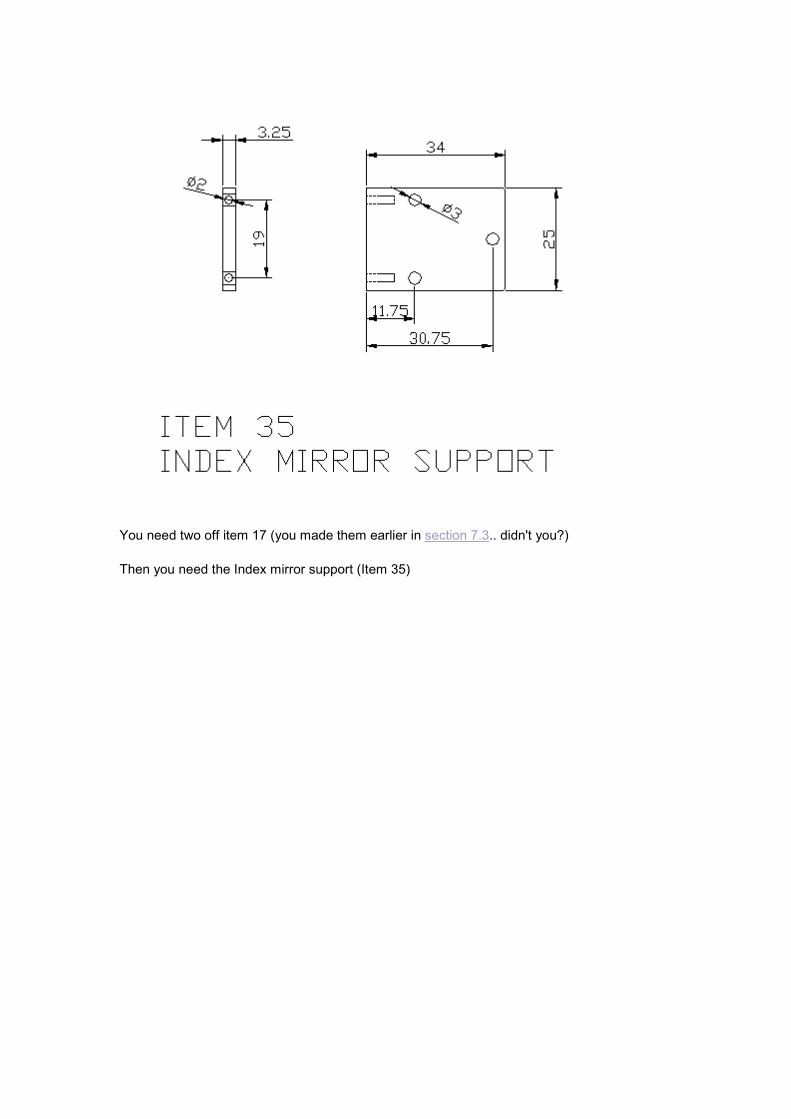
You need two off item 17 (you made them earlier in section 7.3.. didn't you?)
Then you need the Index mirror support (Item 35)
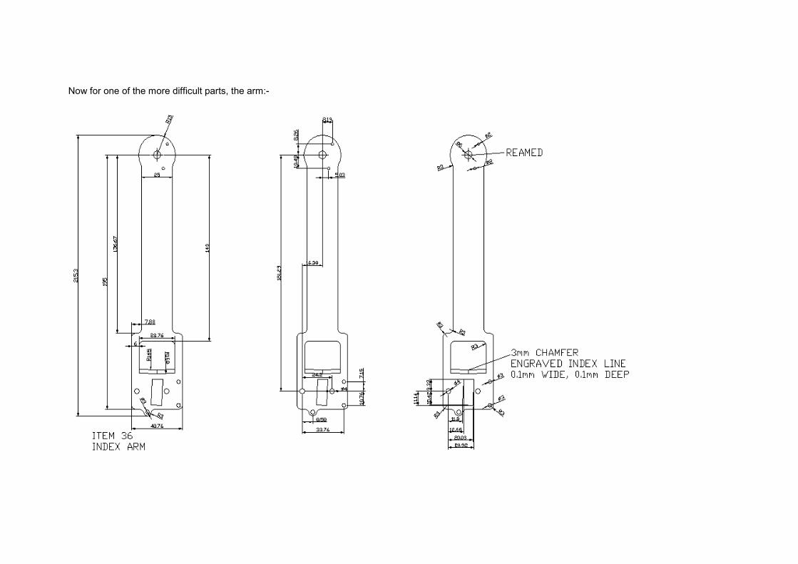
Now for one of the more difficult parts, the arm:-
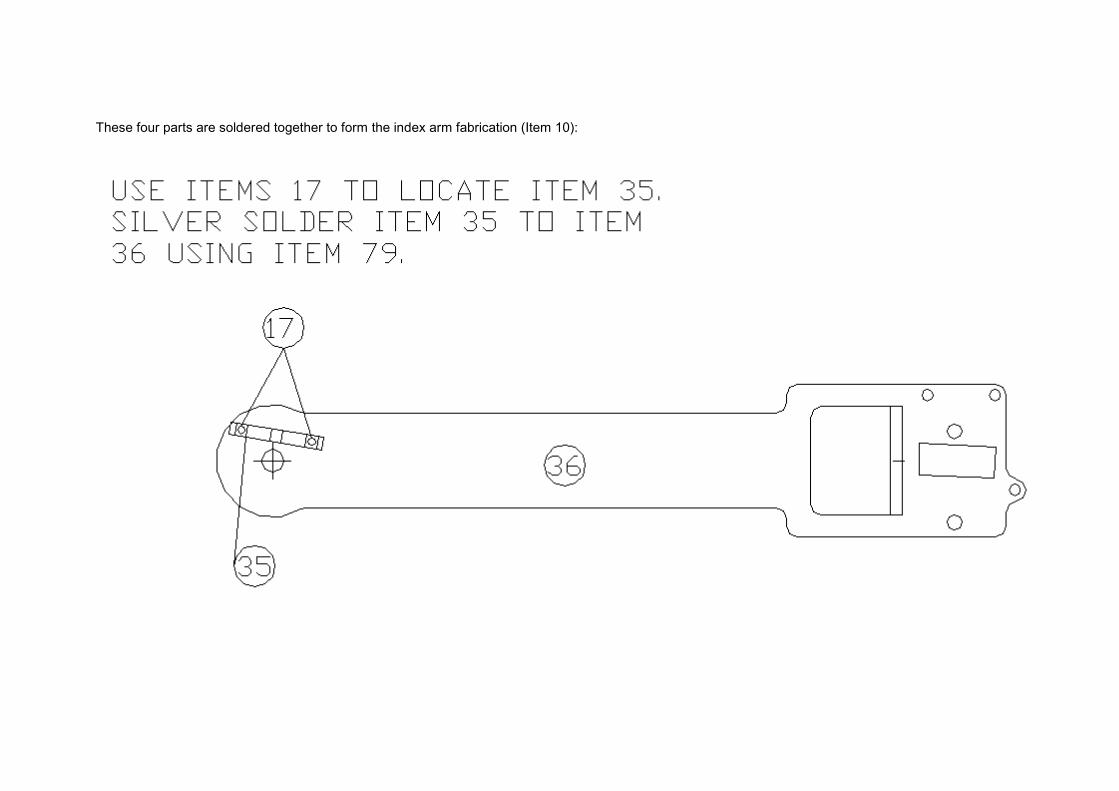
These four parts are soldered together to form the index arm fabrication (Item 10):
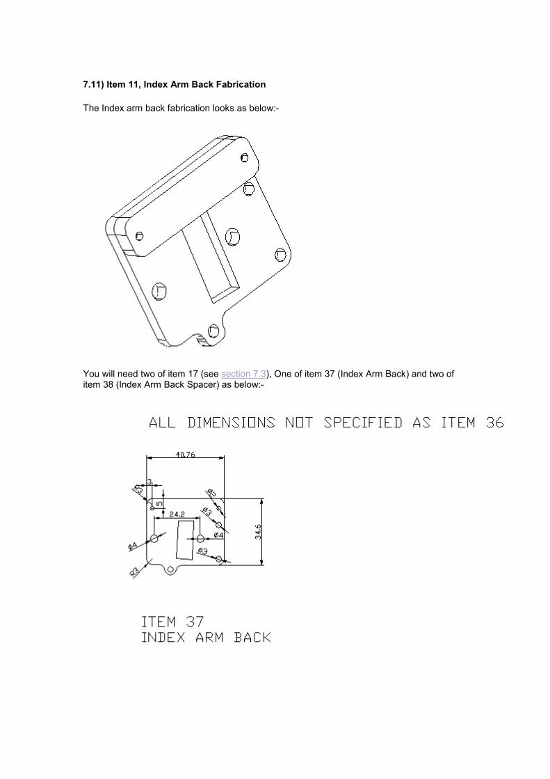
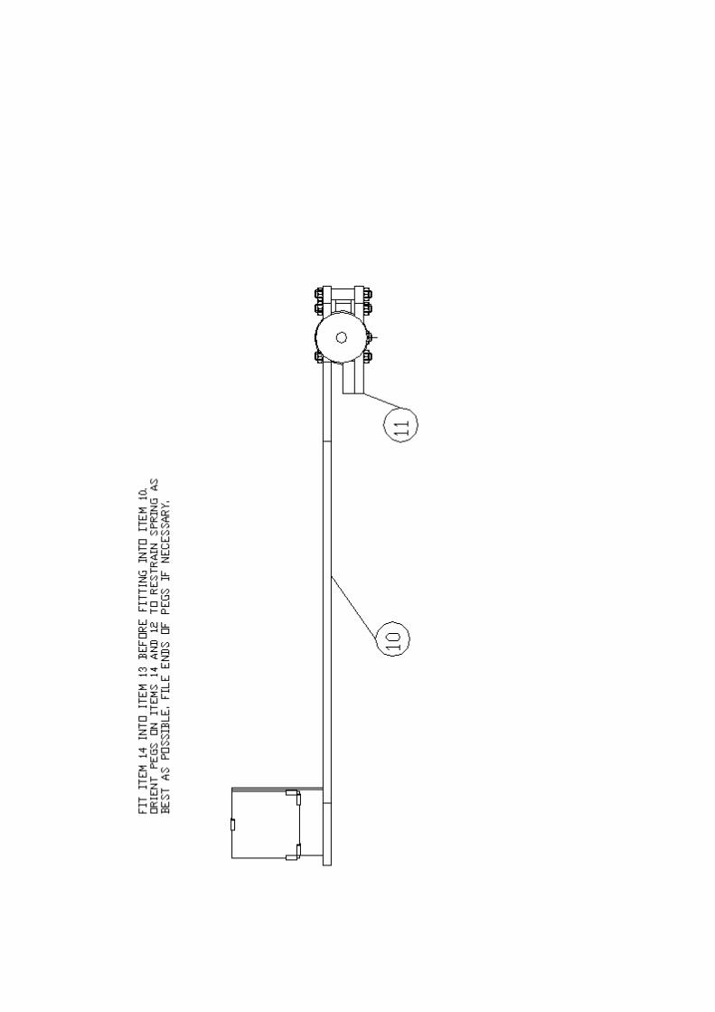
7.11) Item 11, Index Arm Back Fabrication
The Index arm back fabrication looks as below:-
You will need two of item 17 (see section 7.3), One of item 37 (Index Arm Back) and two of item 38 (Index Arm Back Spacer) as below:-
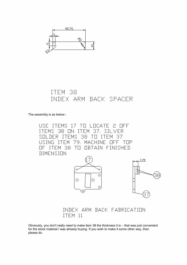
The assembly is as below:-
Obviously, you don't really need to make item 38 the thickness it is – that was just convenient for the stock material I was already buying. If you wish to make it some other way, then please do.
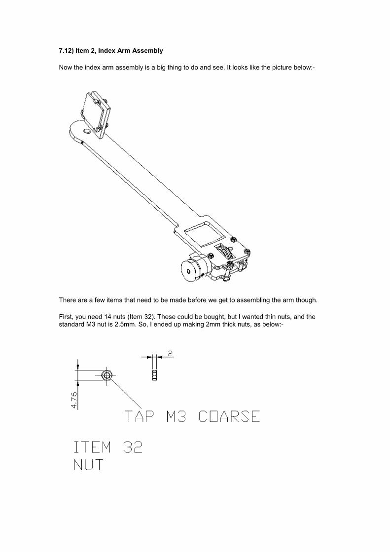
7.12) Item 2, Index Arm Assembly
Now the index arm assembly is a big thing to do and see. It looks like the picture below:-
There are a few items that need to be made before we get to assembling the arm though.
First, you need 14 nuts (Item 32). These could be bought, but I wanted thin nuts, and the standard M3 nut is 2.5mm. So, I ended up making 2mm thick nuts, as below:-
While you're at it you may as well make a further 6 nuts that are required for the main sextant assembly. In actual fact, I was able to get 5mm A/F stock myself rather than the imperial specified, very satisfactory.
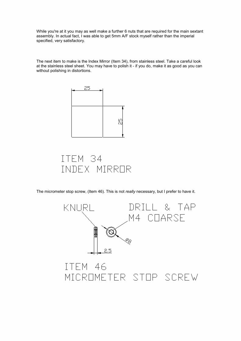
The next item to make is the Index Mirror (Item 34), from stainless steel. Take a careful look at the stainless steel sheet. You may have to polish it - if you do, make it as good as you can without polishing in distortions.
The micrometer stop screw, (Item 46). This is not really necessary, but I prefer to have it.
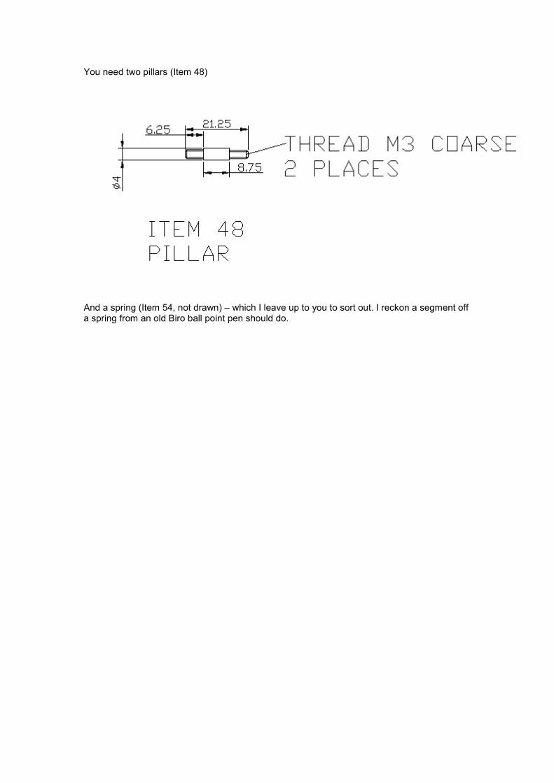
You need two pillars (Item 48)
And a spring (Item 54, not drawn) – which I leave up to you to sort out. I reckon a segment off a spring from an old Biro ball point pen should do.
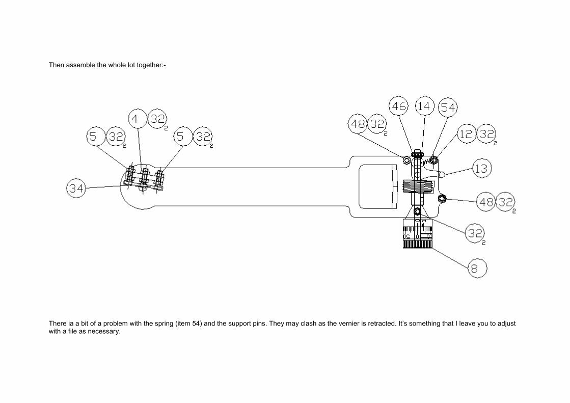
Then assemble the whole lot together:-
There ia a bit of a problem with the spring (item 54) and the support pins. They may clash as the vernier is retracted. It’s something that I leave you to adjustwith a file as necessary.
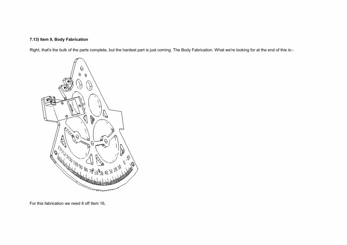
7.13) Item 9, Body Fabrication
Right, that's the bulk of the parts complete, but the hardest part is just coming. The Body Fabrication. What we're looking for at the end of this is:-
For this fabrication we need 8 off Item 16,
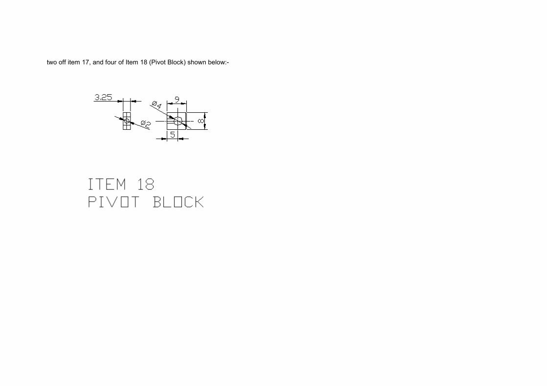
two off item 17, and four of Item 18 (Pivot Block) shown below:-
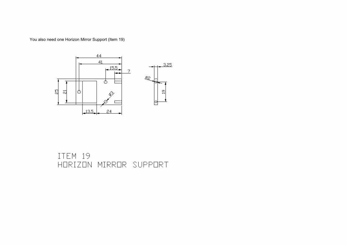
You also need one Horizon Mirror Support (Item 19)
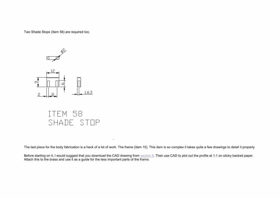
Two Shade Stops (Item 58) are required too,
.
The last piece for the body fabrication is a heck of a lot of work. The frame (Item 15). This item is so complex it takes quite a few drawings to detail it properly
Before starting on it, I would suggest that you download the CAD drawing from section 9. Then use CAD to plot out the profile at 1:1 on sticky backed paper.Attach this to the brass and use it as a guide for the less important parts of the frame.
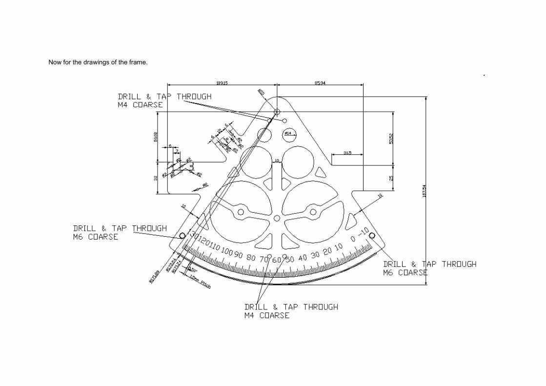
Now for the drawings of the frame.
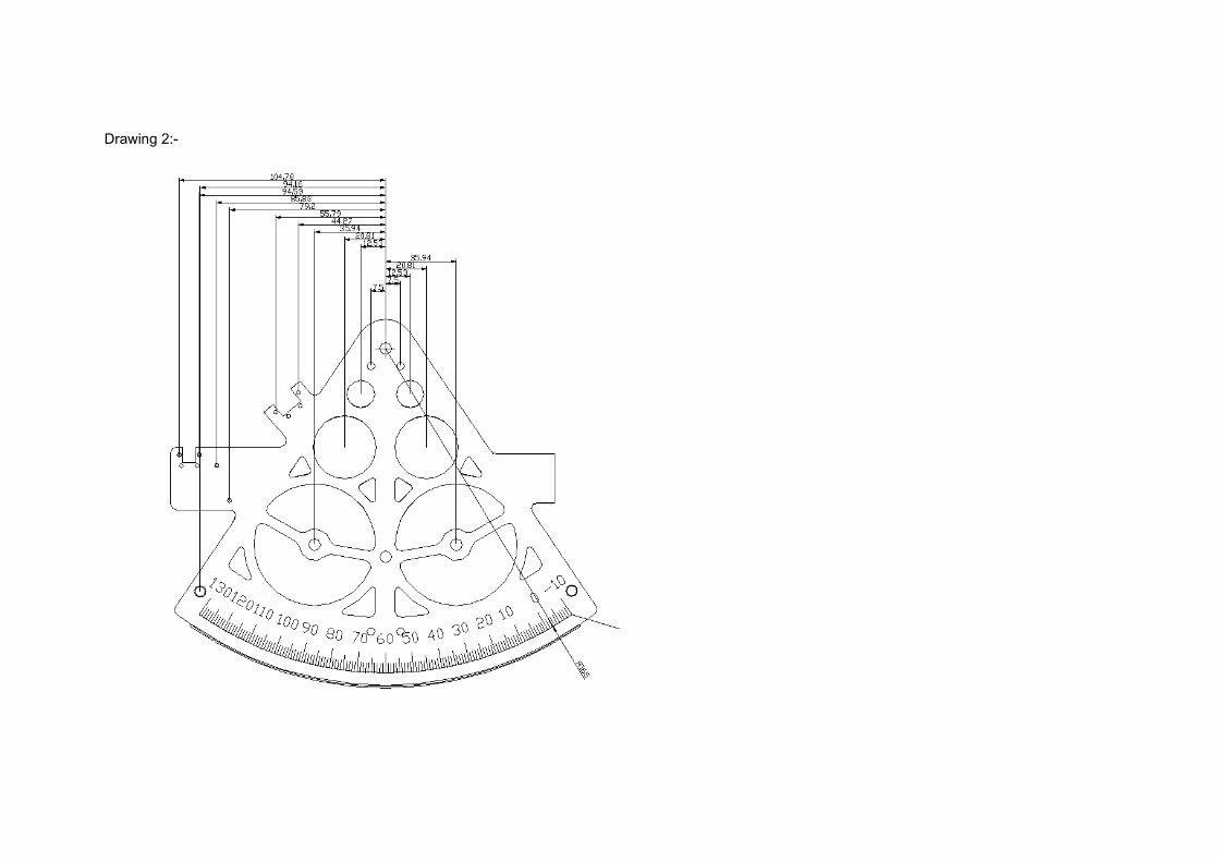
Drawing 2:-
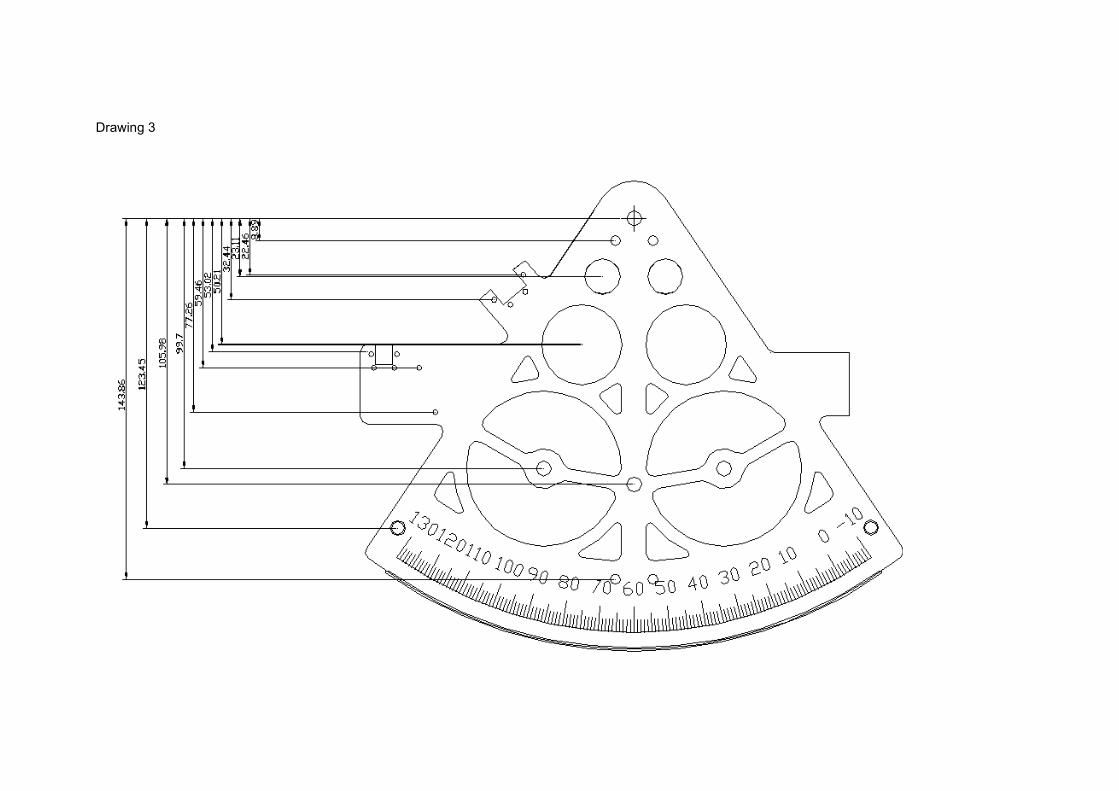
Drawing 3
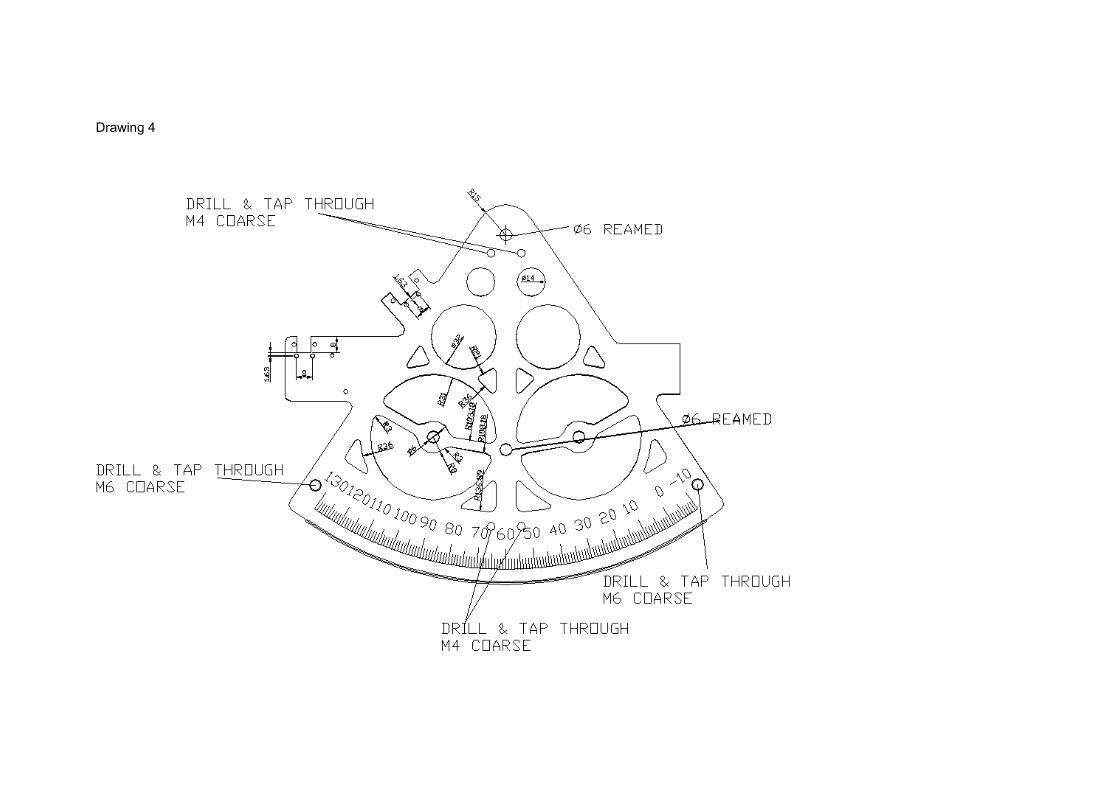
Drawing 4

The following notes apply:-
Cut the gear teeth at the bottom of the arc with the gear cutter shown in section 8.
The gear teeth MUST be cut on the rotary table at exactly 0.5 degrees apart. Ensure that you turn the table the same way all the time and take up backlash inthe mechanism in the same way before each tooth. The entire accuracy of the sextant depends this operation.
Cut the scale graduations with the engraving cutter in section 8.
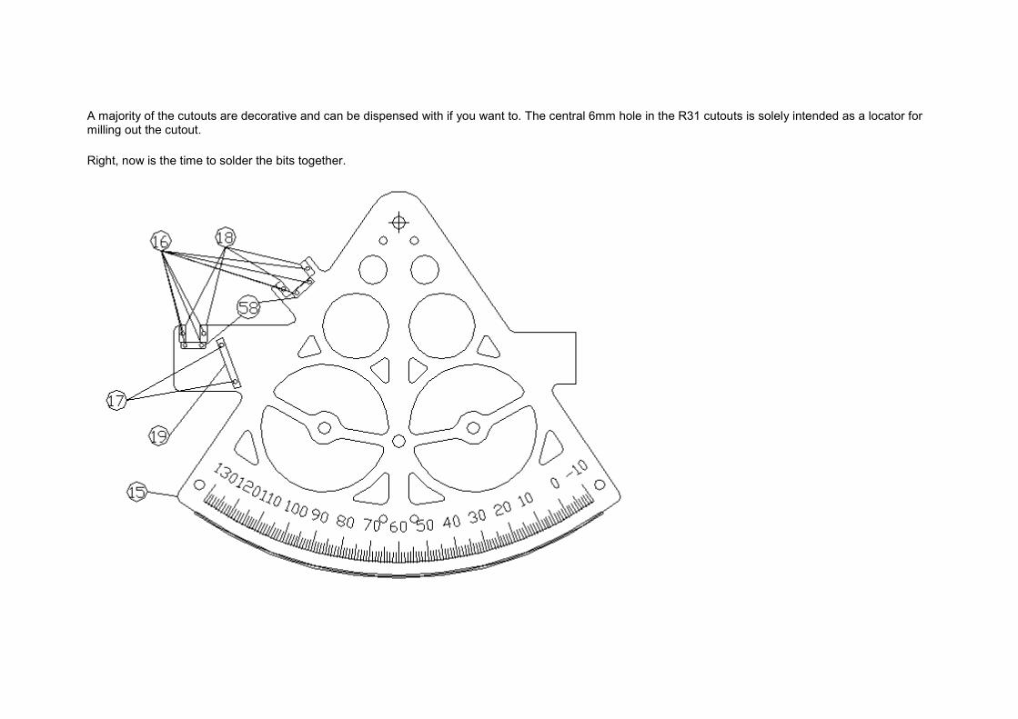
A majority of the cutouts are decorative and can be dispensed with if you want to. The central 6mm hole in the R31 cutouts is solely intended as a locator formilling out the cutout.
Right, now is the time to solder the bits together.
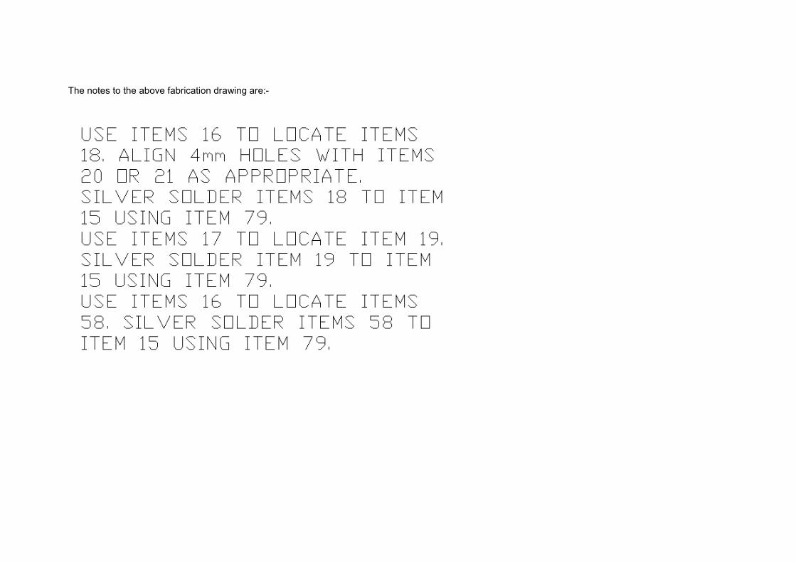
The notes to the above fabrication drawing are:-

7.14) Item 3, Telescope
I can't design a telescope.
That doesn't mean I haven't tried.
Somehow, I just can't work it out. Turning the image the right way up is what stymied my design effort. I've had to resort to buying a toy telescope. I shall be measuring the lens positions, and making a new and firmer housing. It feels like a real failure on my part, not being able to design something as simple as a telescope. I think I need to creep into a corner and sob my misery into my cuff.. No, on second thoughts, that'd be feeble.
The centreline of the telescope is to be 25mm from the surface of the frame, pointing at the horizon mirror. Make sure that the index arm doesn't foul with the telescope support. I think a 3x magnification, 30mm objective lens is a good size to go for.
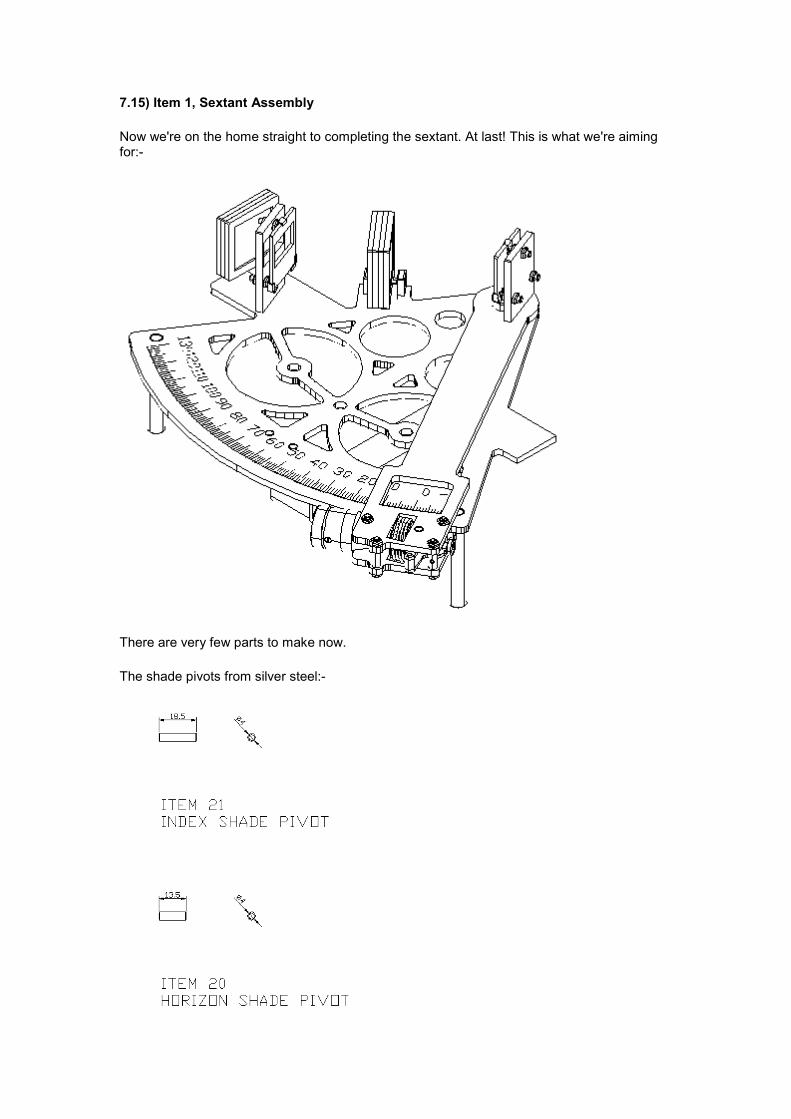
7.15) Item 1, Sextant Assembly
Now we're on the home straight to completing the sextant. At last! This is what we're aiming for:-
There are very few parts to make now.
The shade pivots from silver steel:-
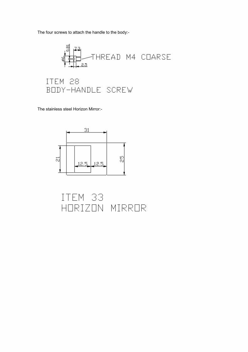
The four screws to attach the handle to the body:-
The stainless steel Horizon Mirror:-
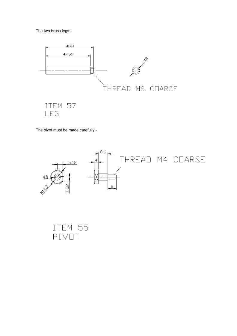
The two brass legs:-
The pivot must be made carefully:-
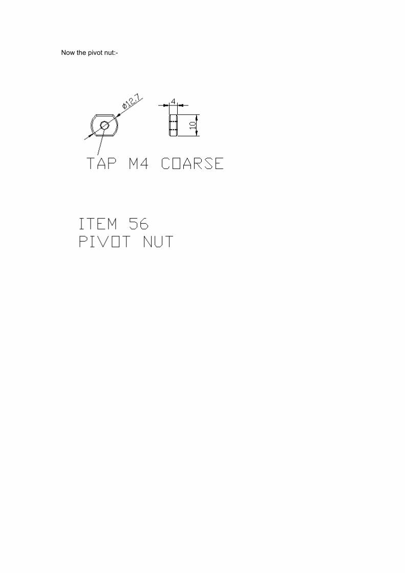
Now the pivot nut:-
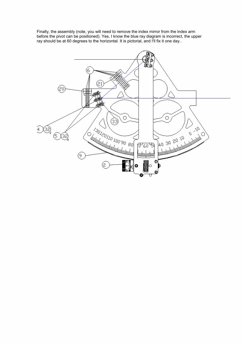
Finally, the assembly (note, you will need to remove the index mirror from the index arm before the pivot can be positioned). Yes, I know the blue ray diagram is incorrect, the upper ray should be at 60 degrees to the horizontal. It is pictorial, and I'll fix it one day..
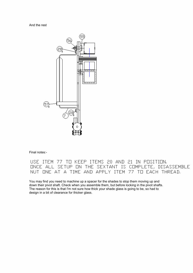
And the rest
Final notes:-
You may find you need to machine up a spacer for the shades to stop them moving up and down their pivot shaft. Check when you assemble them, but before locking in the pivot shafts. The reason for this is that I'm not sure how thick your shade glass is going to be, so had to design in a bit of clearance for thicker glass.
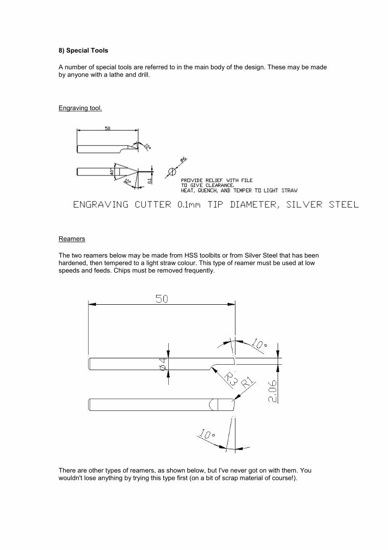
8) Special Tools
A number of special tools are referred to in the main body of the design. These may be made by anyone with a lathe and drill.
Engraving tool.
Reamers
The two reamers below may be made from HSS toolbits or from Silver Steel that has been hardened, then tempered to a light straw colour. This type of reamer must be used at low speeds and feeds. Chips must be removed frequently.
There are other types of reamers, as shown below, but I've never got on with them. You wouldn't lose anything by trying this type first (on a bit of scrap material of course!).
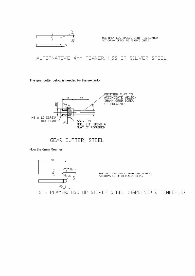
The gear cutter below is needed for the sextant:-
Now the 6mm Reamer
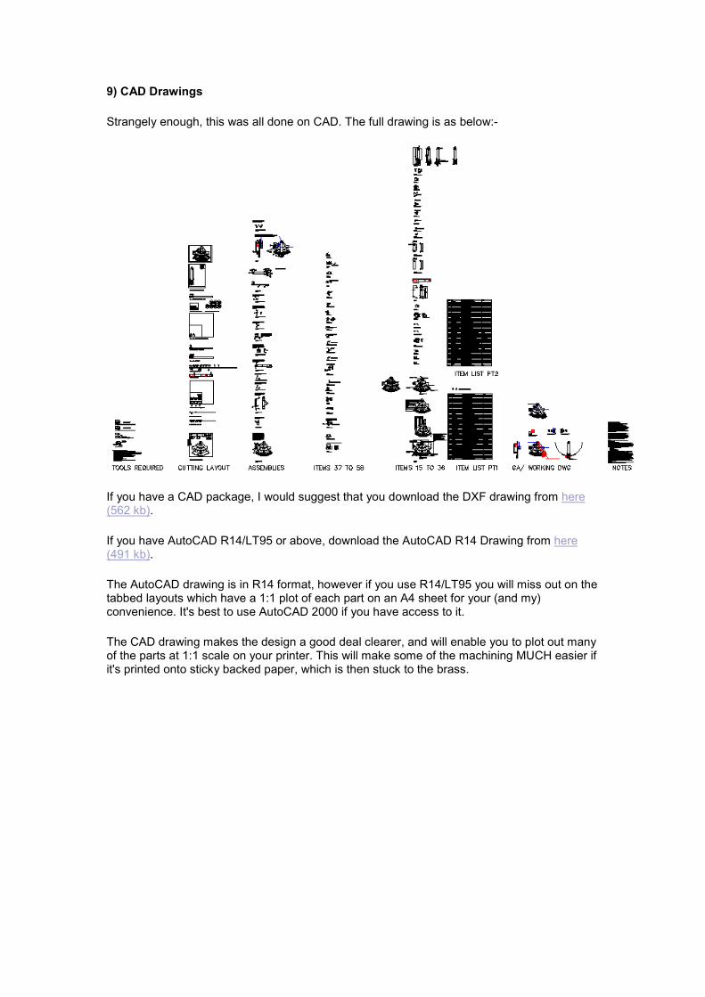
9) CAD Drawings
Strangely enough, this was all done on CAD. The full drawing is as below:-
If you have a CAD package, I would suggest that you download the DXF drawing from here (562 kb).
If you have AutoCAD R14/LT95 or above, download the AutoCAD R14 Drawing from here (491 kb).
The AutoCAD drawing is in R14 format, however if you use R14/LT95 you will miss out on the tabbed layouts which have a 1:1 plot of each part on an A4 sheet for your (and my) convenience. It's best to use AutoCAD 2000 if you have access to it.
The CAD drawing makes the design a good deal clearer, and will enable you to plot out many of the parts at 1:1 scale on your printer. This will make some of the machining MUCH easier if it's printed onto sticky backed paper, which is then stuck to the brass.
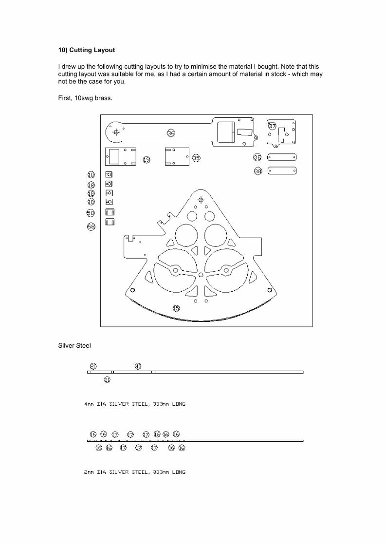
10) Cutting Layout
I drew up the following cutting layouts to try to minimise the material I bought. Note that this cutting layout was suitable for me, as I had a certain amount of material in stock - which may not be the case for you.
First, 10swg brass.
Silver Steel
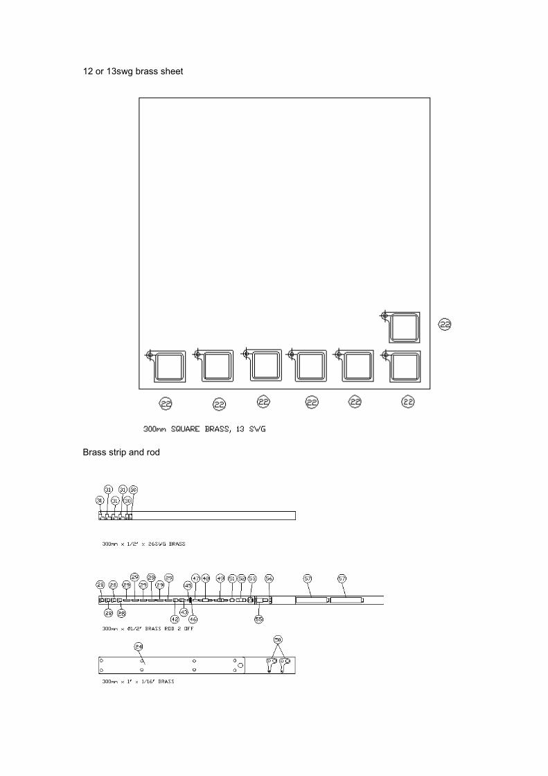
12 or 13swg brass sheet
Brass strip and rod
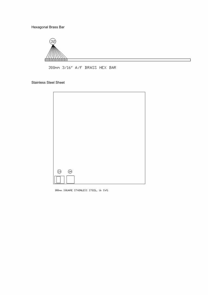
Hexagonal Brass Bar
Stainless Steel Sheet
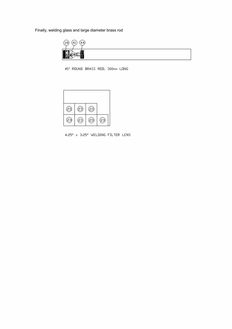
Finally, welding glass and large diameter brass rod
11) And Finally...
All you have to do now is.. Calibration, error correction and use.
Calibration and Error Correction
Calibration and error correction is not something I will go into in great detail, as there are plenty of publications that go into this, not least of which is the 'Instruments for Celestial Navigation' chapter [No. 16] of Bowditch 'The American Practical Navigator'. There are two types of error, Non adjustable Errors and Adjustable Errors. These are discussed below:-
Non-Adjustable Errors
These errors are almost entirely down to the accuracy of your manufacturing, so can be virtually eliminated with careful manufacturing procedure.
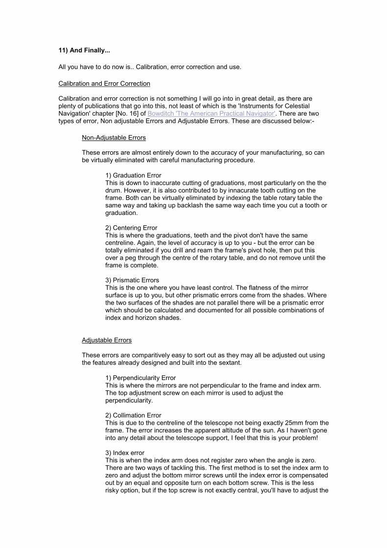
1) Graduation Error This is down to inaccurate cutting of graduations, most particularly on the the drum. However, it is also contributed to by innacurate tooth cutting on the frame. Both can be virtually eliminated by indexing the table rotary table the same way and taking up backlash the same way each time you cut a tooth or graduation. 2) Centering Error This is where the graduations, teeth and the pivot don't have the same centreline. Again, the level of accuracy is up to you - but the error can be totally eliminated if you drill and ream the frame's pivot hole, then put this over a peg through the centre of the rotary table, and do not remove until the frame is complete. 3) Prismatic Errors This is the one where you have least control. The flatness of the mirror surface is up to you, but other prismatic errors come from the shades. Where the two surfaces of the shades are not parallel there will be a prismatic error which should be calculated and documented for all possible combinations of index and horizon shades.
Adjustable Errors
These errors are comparitively easy to sort out as they may all be adjusted out using the features already designed and built into the sextant.
1) Perpendicularity Error This is where the mirrors are not perpendicular to the frame and index arm. The top adjustment screw on each mirror is used to adjust the perpendicularity. 2) Collimation Error This is due to the centreline of the telescope not being exactly 25mm from the frame. The error increases the apparent altitude of the sun. As I haven't gone into any detail about the telescope support, I feel that this is your problem! 3) Index error This is when the index arm does not register zero when the angle is zero. There are two ways of tackling this. The first method is to set the index arm to zero and adjust the bottom mirror screws until the index error is compensated out by an equal and opposite turn on each bottom screw. This is the less risky option, but if the top screw is not exactly central, you'll have to adjust the
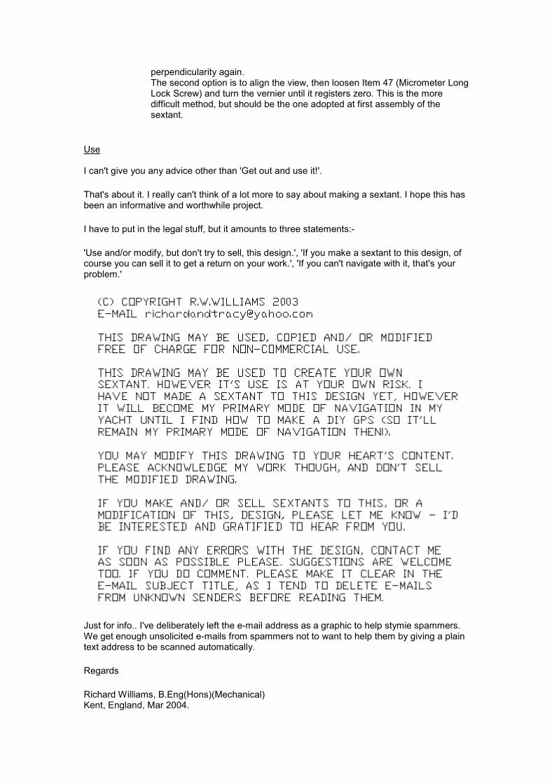
perpendicularity again. The second option is to align the view, then loosen Item 47 (Micrometer Long Lock Screw) and turn the vernier until it registers zero. This is the more difficult method, but should be the one adopted at first assembly of the sextant.
Use
I can't give you any advice other than 'Get out and use it!'.
That's about it. I really can't think of a lot more to say about making a sextant. I hope this has been an informative and worthwhile project.
I have to put in the legal stuff, but it amounts to three statements:-
'Use and/or modify, but don't try to sell, this design.', 'If you make a sextant to this design, of course you can sell it to get a return on your work.', 'If you can't navigate with it, that's your problem.'
Just for info.. I've deliberately left the e-mail address as a graphic to help stymie spammers. We get enough unsolicited e-mails from spammers not to want to help them by giving a plain text address to be scanned automatically.
Regards
Richard Williams, B.Eng(Hons)(Mechanical) Kent, England, Mar 2004.
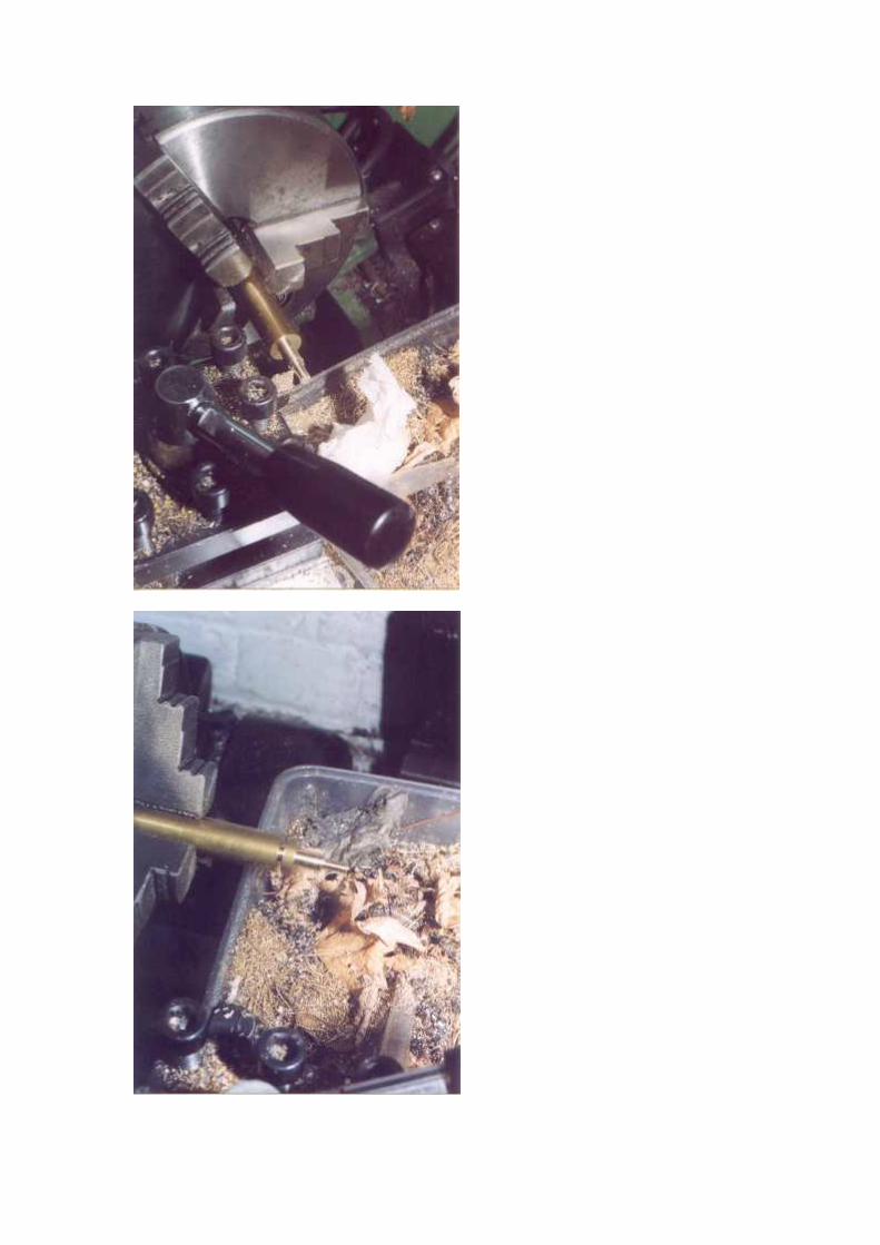
12) Progress
Right. How far have I actually got? Not very far really. So far I've been concentrating on doing the fiddly little bits, while working up my nerve to attack some of the bigger milling jobs. Anyway, the photos below show what progress I've made to Mid Dec 2003 (when I took the photos). I'll add more photos when I've finished the film I've got in my camera. And, yes, I do have a very low tech, entirely mechanical, SLR film camera - but I didn't make it myself! (I can't do optics, remember?)
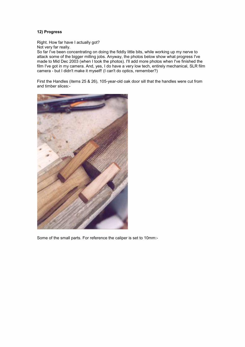
First the Handles (items 25 & 26), 105-year-old oak door sill that the handles were cut from and timber slices:-
Some of the small parts. For reference the caliper is set to 10mm:-
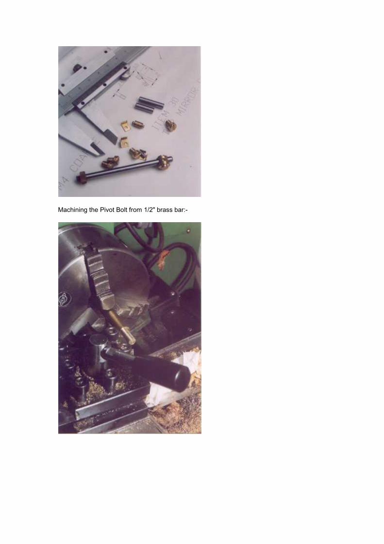
Machining the Pivot Bolt from 1/2" brass bar:-