Embed Size (px)
Citation preview
AUTOMOTIVE ENGINEERING
AUTOMOTIVE WORKSHOP
AUTO 109
NOTES
Vassiliades Andreas
AUTO 109 - Automotive Workshop 1
LENGTH MEASURING INSTRUMENTS
- Vernier scale
- Caliper
- Micrometer
- Slip Gauges
- Dial Indicator / gauges
- Surface Roughness
AUTO 109 - Automotive Workshop 2
Vernier scale
A vernier scale lets one read more precisely from an evenly divided straight or circular measurement scale. It is fitted with a sliding secondary scale that is used to indicate where the measurement lies when it is in-between two of the marks on the main scale.
It was invented in its modern form in 1631 by the French mathematician Pierre Vernier (1580–1637). In some languages, this device is called a nonius, which is the latin name of the Portuguese astronomer and mathematician Pedro Nunes (1492–1578) who invented the principle.
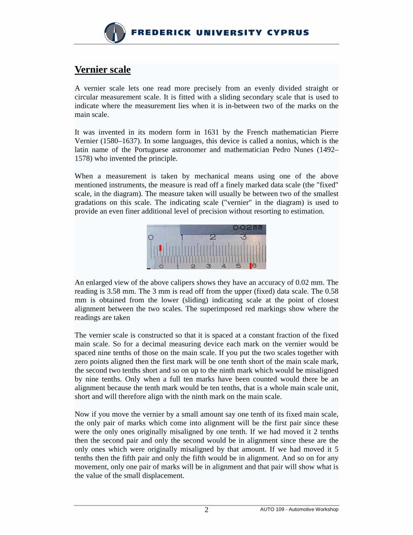
When a measurement is taken by mechanical means using one of the above mentioned instruments, the measure is read off a finely marked data scale (the "fixed" scale, in the diagram). The measure taken will usually be between two of the smallest gradations on this scale. The indicating scale ("vernier" in the diagram) is used to provide an even finer additional level of precision without resorting to estimation.
An enlarged view of the above calipers shows they have an accuracy of 0.02 mm. The reading is 3.58 mm. The 3 mm is read off from the upper (fixed) data scale. The 0.58 mm is obtained from the lower (sliding) indicating scale at the point of closest alignment between the two scales. The superimposed red markings show where the readings are taken
The vernier scale is constructed so that it is spaced at a constant fraction of the fixed main scale. So for a decimal measuring device each mark on the vernier would be spaced nine tenths of those on the main scale. If you put the two scales together with zero points aligned then the first mark will be one tenth short of the main scale mark, the second two tenths short and so on up to the ninth mark which would be misaligned by nine tenths. Only when a full ten marks have been counted would there be an alignment because the tenth mark would be ten tenths, that is a whole main scale unit, short and will therefore align with the ninth mark on the main scale.
Now if you move the vernier by a small amount say one tenth of its fixed main scale, the only pair of marks which come into alignment will be the first pair since these were the only ones originally misaligned by one tenth. If we had moved it 2 tenths then the second pair and only the second would be in alignment since these are the only ones which were originally misaligned by that amount. If we had moved it 5 tenths then the fifth pair and only the fifth would be in alignment. And so on for any movement, only one pair of marks will be in alignment and that pair will show what is the value of the small displacement.
AUTO 109 - Automotive Workshop 3
Caliper
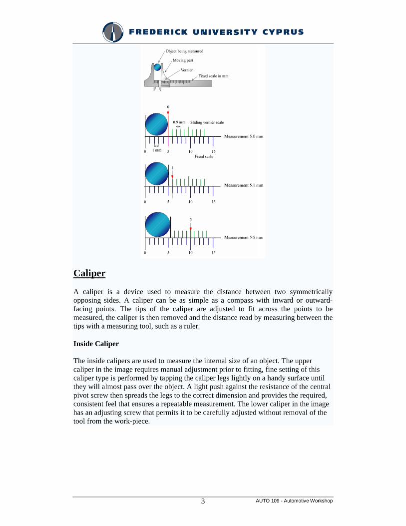
A caliper is a device used to measure the distance between two symmetrically opposing sides. A caliper can be as simple as a compass with inward or outward-facing points. The tips of the caliper are adjusted to fit across the points to be measured, the caliper is then removed and the distance read by measuring between the tips with a measuring tool, such as a ruler.
Inside Caliper
The inside calipers are used to measure the internal size of an object. The upper caliper in the image requires manual adjustment prior to fitting, fine setting of this caliper type is performed by tapping the caliper legs lightly on a handy surface until they will almost pass over the object. A light push against the resistance of the central pivot screw then spreads the legs to the correct dimension and provides the required, consistent feel that ensures a repeatable measurement. The lower caliper in the image has an adjusting screw that permits it to be carefully adjusted without removal of the tool from the work-piece.
AUTO 109 - Automotive Workshop 4
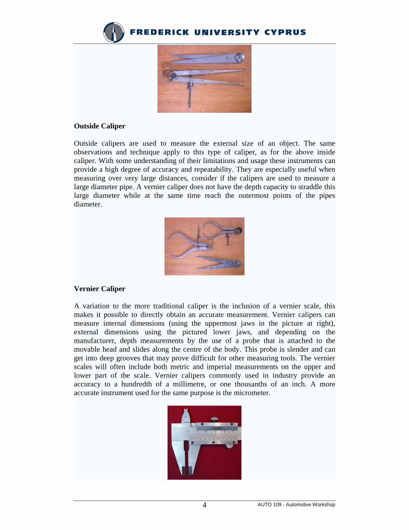
Outside Caliper
Outside calipers are used to measure the external size of an object. The same observations and technique apply to this type of caliper, as for the above inside caliper. With some understanding of their limitations and usage these instruments can provide a high degree of accuracy and repeatability. They are especially useful when measuring over very large distances, consider if the calipers are used to measure a large diameter pipe. A vernier caliper does not have the depth capacity to straddle this large diameter while at the same time reach the outermost points of the pipes diameter.
Vernier Caliper
A variation to the more traditional caliper is the inclusion of a vernier scale, this makes it possible to directly obtain an accurate measurement. Vernier calipers can measure internal dimensions (using the uppermost jaws in the picture at right), external dimensions using the pictured lower jaws, and depending on the manufacturer, depth measurements by the use of a probe that is attached to the movable head and slides along the centre of the body. This probe is slender and can get into deep grooves that may prove difficult for other measuring tools. The vernier scales will often include both metric and imperial measurements on the upper and lower part of the scale. Vernier calipers commonly used in industry provide an accuracy to a hundredth of a millimetre, or one thousanths of an inch. A more accurate instrument used for the same purpose is the micrometer.
AUTO 109 - Automotive Workshop 5
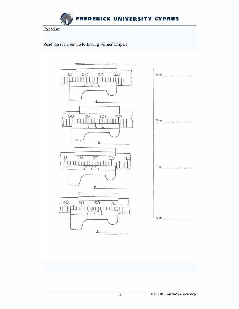
Exercise:
Read the scale on the following vernier calipers
AUTO 109 - Automotive Workshop 6
Dial Caliper
A further refinement to the vernier caliper is the dial caliper. In this instrument, a small gear rack drives a pointer on a circular dial. Typically, the pointer rotates once every inch, tenth of an inch, or 10 millimetres, allowing for a very accurate and direct reading without the need to interpolate a vernier scale (although one still needs to add the basic inches or tens of millimeters value read from the slide of the caliper). The dial is usually arranged to be rotatable beneath the pointer, allowing for easy "differential" measurements (the measuring of the difference in size between two objects, or the setting of the dial using a master object and subsequently being able to read directly the plus-or-minus variance in size of subsequent objects relative to the master object).
Digital Caliper
A refinement now popular is the replacement of the analog dial with an electronic digital display. This version of the caliper finally allows simply reading the value directly from a single display. Many digital calipers can also be switched between metric and English units and all provide for zeroing the display at any point along the slide, allowing the same sort of differential measurements as with the dial caliper but without the need to read numbers that may be upside down. Digital calipers may also contain some sort of "reading hold" feature, allowing the reading of dimensions even in very awkward locations where the display cannot be directly seen.
Micrometer
A micrometer is a widely used device in mechanical engineering for precisely measuring thickness of blocks, outer and inner diameters of shafts and depths of slots. Appearing frequently in metrology, the study of measurement, micrometers have several advantages over other types of measuring instruments like the Vernier caliper - they are easy to use and their readouts are consistent.
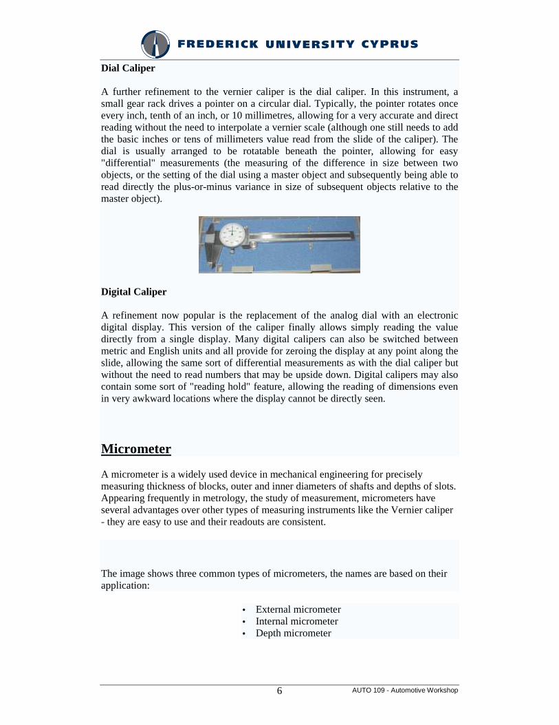
The image shows three common types of micrometers, the names are based on their application:
• External micrometer • Internal micrometer • Depth micrometer
AUTO 109 - Automotive Workshop 7
An external micrometer is typically used to measure wires, spheres, shafts and blocks. An internal micrometer is used to measure the opening of holes, and a depth micrometer typically measures depths of slots and steps.
The precision of a micrometer is achieved by a using a fine pitch screw mechanism.
An additional interesting feature of micrometers is the inclusion of a spring-loaded twisting handle. Normally, one could use the mechanical advantage of the screw to force the micrometer to squeeze the material, giving an inaccurate measurement. However, by attaching a handle that will ratchet at a certain torque, the micrometer will not continue to advance once sufficient resistance is encountered.
Reading an inch-system micrometer
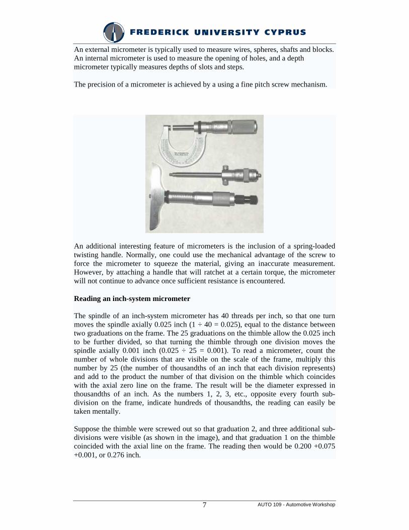
The spindle of an inch-system micrometer has 40 threads per inch, so that one turn moves the spindle axially 0.025 inch (1 ÷ 40 = 0.025), equal to the distance between two graduations on the frame. The 25 graduations on the thimble allow the 0.025 inch to be further divided, so that turning the thimble through one division moves the spindle axially 0.001 inch (0.025 ÷ 25 = 0.001). To read a micrometer, count the number of whole divisions that are visible on the scale of the frame, multiply this number by 25 (the number of thousandths of an inch that each division represents) and add to the product the number of that division on the thimble which coincides with the axial zero line on the frame. The result will be the diameter expressed in thousandths of an inch. As the numbers 1, 2, 3, etc., opposite every fourth sub-division on the frame, indicate hundreds of thousandths, the reading can easily be taken mentally.
Suppose the thimble were screwed out so that graduation 2, and three additional sub-divisions were visible (as shown in the image), and that graduation 1 on the thimble coincided with the axial line on the frame. The reading then would be 0.200 +0.075 +0.001, or 0.276 inch.
AUTO 109 - Automotive Workshop 8
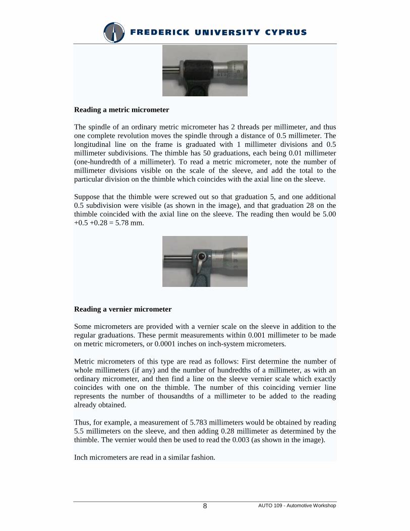
Reading a metric micrometer
The spindle of an ordinary metric micrometer has 2 threads per millimeter, and thus one complete revolution moves the spindle through a distance of 0.5 millimeter. The longitudinal line on the frame is graduated with 1 millimeter divisions and 0.5 millimeter subdivisions. The thimble has 50 graduations, each being 0.01 millimeter (one-hundredth of a millimeter). To read a metric micrometer, note the number of millimeter divisions visible on the scale of the sleeve, and add the total to the particular division on the thimble which coincides with the axial line on the sleeve.
Suppose that the thimble were screwed out so that graduation 5, and one additional 0.5 subdivision were visible (as shown in the image), and that graduation 28 on the thimble coincided with the axial line on the sleeve. The reading then would be 5.00 +0.5 +0.28 = 5.78 mm.
Reading a vernier micrometer
Some micrometers are provided with a vernier scale on the sleeve in addition to the regular graduations. These permit measurements within 0.001 millimeter to be made on metric micrometers, or 0.0001 inches on inch-system micrometers.
Metric micrometers of this type are read as follows: First determine the number of whole millimeters (if any) and the number of hundredths of a millimeter, as with an ordinary micrometer, and then find a line on the sleeve vernier scale which exactly coincides with one on the thimble. The number of this coinciding vernier line represents the number of thousandths of a millimeter to be added to the reading already obtained.
Thus, for example, a measurement of 5.783 millimeters would be obtained by reading 5.5 millimeters on the sleeve, and then adding 0.28 millimeter as determined by the thimble. The vernier would then be used to read the 0.003 (as shown in the image).
Inch micrometers are read in a similar fashion.
AUTO 109 - Automotive Workshop 9
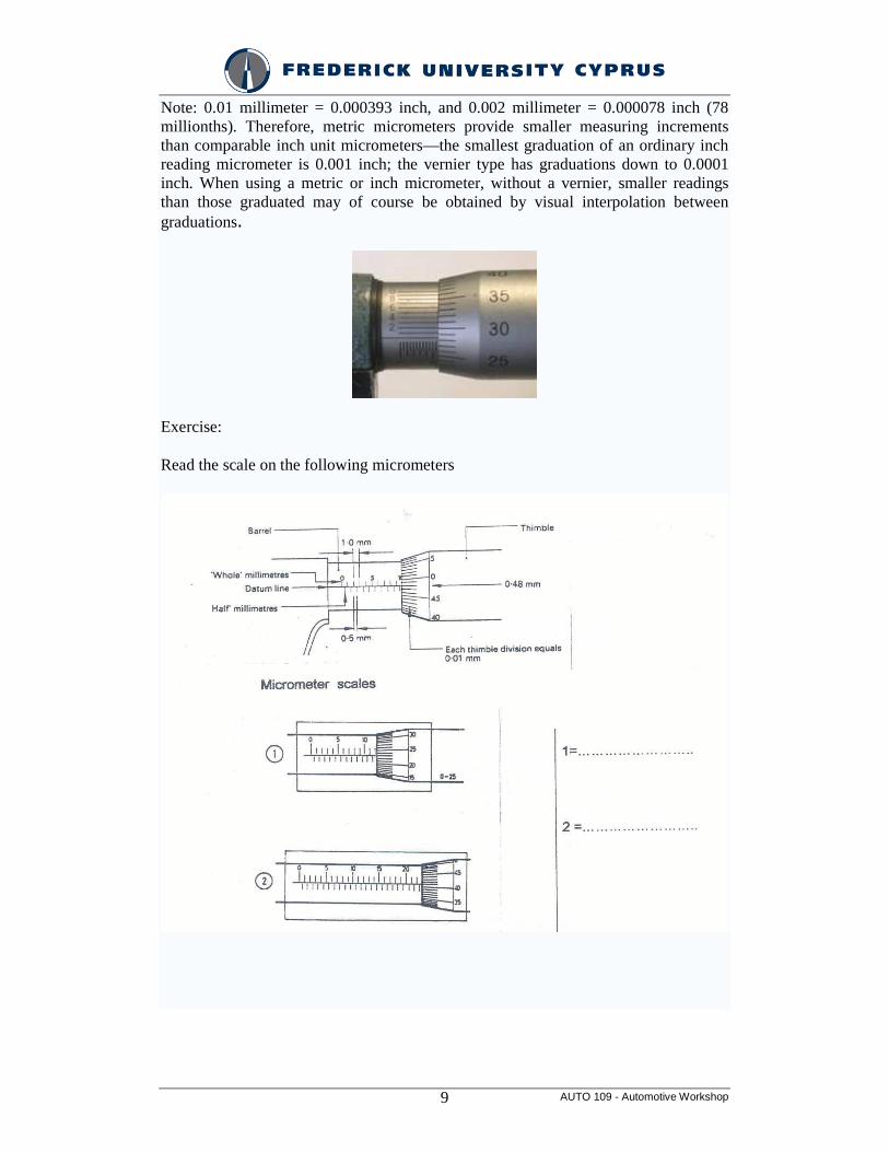
Note: 0.01 millimeter = 0.000393 inch, and 0.002 millimeter = 0.000078 inch (78 millionths). Therefore, metric micrometers provide smaller measuring increments than comparable inch unit micrometers—the smallest graduation of an ordinary inch reading micrometer is 0.001 inch; the vernier type has graduations down to 0.0001 inch. When using a metric or inch micrometer, without a vernier, smaller readings than those graduated may of course be obtained by visual interpolation between graduations.
Exercise:
Read the scale on the following micrometers
AUTO 109 - Automotive Workshop 10
Slip Gauges
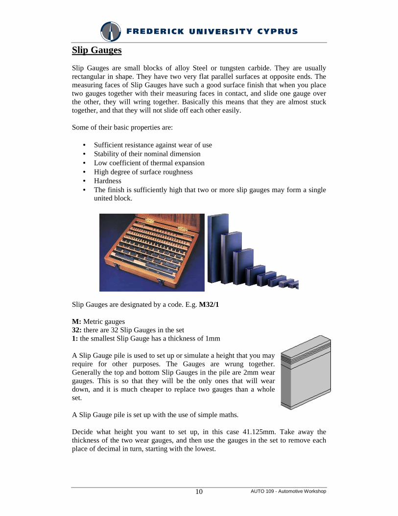
Slip Gauges are small blocks of alloy Steel or tungsten carbide. They are usually rectangular in shape. They have two very flat parallel surfaces at opposite ends. The measuring faces of Slip Gauges have such a good surface finish that when you place two gauges together with their measuring faces in contact, and slide one gauge over the other, they will wring together. Basically this means that they are almost stuck together, and that they will not slide off each other easily.
Some of their basic properties are:
• Sufficient resistance against wear of use • Stability of their nominal dimension • Low coefficient of thermal expansion • High degree of surface roughness • Hardness • The finish is sufficiently high that two or more slip gauges may form a single
united block.
Slip Gauges are designated by a code. E.g. M32/1
M: Metric gauges 32: there are 32 Slip Gauges in the set 1: the smallest Slip Gauge has a thickness of 1mm
A Slip Gauge pile is used to set up or simulate a height that you may require for other purposes. The Gauges are wrung together. Generally the top and bottom Slip Gauges in the pile are 2mm wear gauges. This is so that they will be the only ones that will wear down, and it is much cheaper to replace two gauges than a whole set.
A Slip Gauge pile is set up with the use of simple maths.
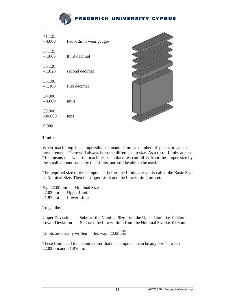
Decide what height you want to set up, in this case 41.125mm. Take away the thickness of the two wear gauges, and then use the gauges in the set to remove each place of decimal in turn, starting with the lowest.
AUTO 109 - Automotive Workshop 11
.
41.125 - 4.000 ______ 37.125 - 1.005 _______ 36.120 - 1.020 _______ 35.100 - 1.100 _______ 34.000 - 4.000 _______ 30.000 -30.000 _______ 0.000
two x 2mm wear gauges third decimal second decimal first decimal units tens
Limits
When machining it is impossible to manufacture a number of pieces to an exact measurement. There will always be some difference in size. As a result Limits are set. This means that what the machinist manufactures can differ from the proper size by the small amount stated by the Limits, and still be able to be used.
The required size of the component, before the Limits are set, is called the Basic Size or Nominal Size. Then the Upper Limit and the Lower Limit are set.
E.g. 22.00mm ---- Nominal Size 22.02mm ---- Upper Limit 21.97mm ---- Lower Limit
To get the:
Upper Deviation ---- Subtract the Nominal Size from the Upper Limit. i.e. 0.02mm Lower Deviation ---- Subtract the Lower Limit from the Nominal Size i.e. 0.03mm
Limits are usually written in this way: 22.00
These Limits tell the manufacturer that the component can be any size between 22.02mm and 21.97mm.
AUTO 109 - Automotive Workshop 12
Tolerance
The Tolerance is the difference between the Upper Limit and the Lower Limit.
i.e. 0.05mm
The Tolerance is the total amount by which the size of the component can differ from the Nominal Size.
A Tolerance is said to be Bilateral if it is spread over both sides of the Nominal Size. The above example is an example of a Bilateral Tolerance.
A Tolerance is said to be Unilateral if it is only on one side of the Nominal Size. E.g. 22.00
These Limits tell the manufacturer that the component can be any size between 22.00mm and 22.02mm.
They are available in various grades depending on their intended use.
• reference (AAA) — high tolerance (± 0.00005mm or 0.000002") • calibration (AA) — (tolerance +0.00010mm to -0.00005mm) • inspection (A) — (tolerance +0.00015mm to -0.0005mm) • workshop (B) — low tolerance (tolerance +0.00025mm to -0.00015mm)
Dial Indicator/gauges
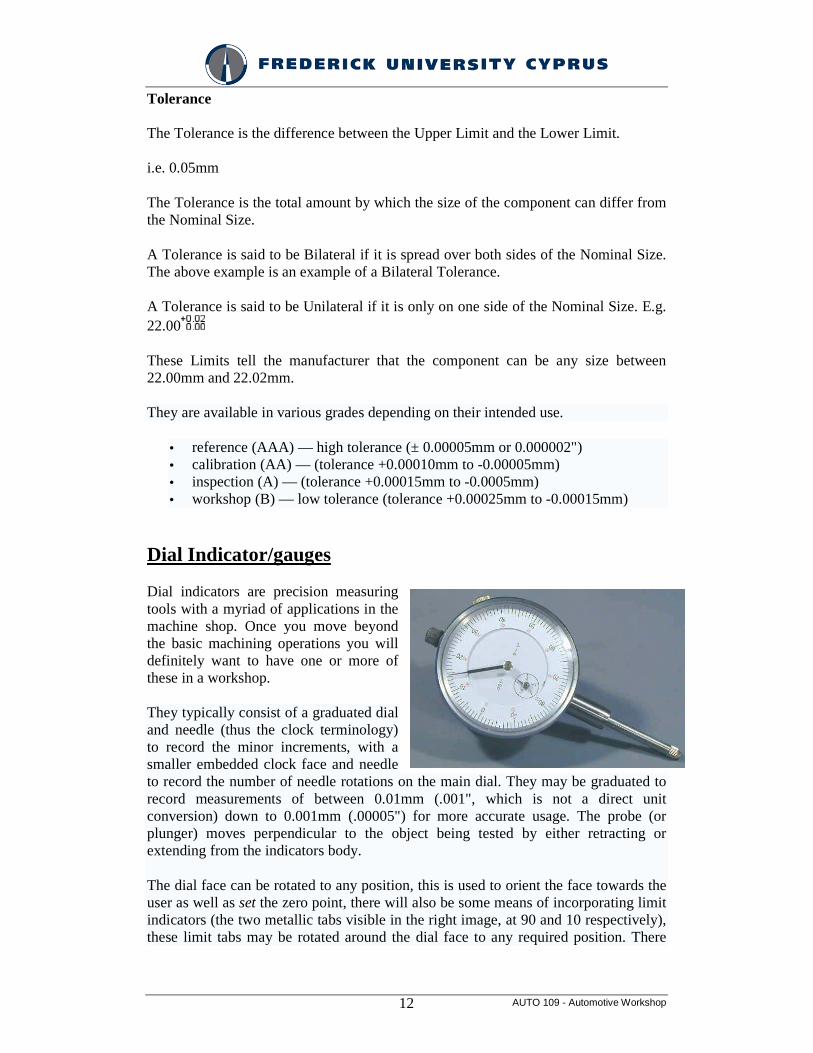
Dial indicators are precision measuring tools with a myriad of applications in the machine shop. Once you move beyond the basic machining operations you will definitely want to have one or more of these in a workshop.
They typically consist of a graduated dial and needle (thus the clock terminology) to record the minor increments, with a smaller embedded clock face and needle to record the number of needle rotations on the main dial. They may be graduated to record measurements of between 0.01mm (.001", which is not a direct unit conversion) down to 0.001mm (.00005") for more accurate usage. The probe (or plunger) moves perpendicular to the object being tested by either retracting or extending from the indicators body.
The dial face can be rotated to any position, this is used to orient the face towards the user as well as set the zero point, there will also be some means of incorporating limit indicators (the two metallic tabs visible in the right image, at 90 and 10 respectively), these limit tabs may be rotated around the dial face to any required position. There
AUTO 109 - Automotive Workshop 13
may also be a lever arm available that will allow the indicator's probe to be retracted easily.
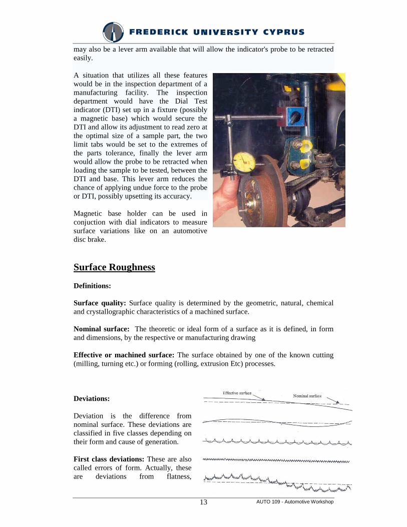
A situation that utilizes all these features would be in the inspection department of a manufacturing facility. The inspection department would have the Dial Test indicator (DTI) set up in a fixture (possibly a magnetic base) which would secure the DTI and allow its adjustment to read zero at the optimal size of a sample part, the two limit tabs would be set to the extremes of the parts tolerance, finally the lever arm would allow the probe to be retracted when loading the sample to be tested, between the DTI and base. This lever arm reduces the chance of applying undue force to the probe or DTI, possibly upsetting its accuracy.
Magnetic base holder can be used in conjuction with dial indicators to measure surface variations like on an automotive disc brake.
Surface Roughness
Definitions:
Surface quality: Surface quality is determined by the geometric, natural, chemical and crystallographic characteristics of a machined surface.
Nominal surface: The theoretic or ideal form of a surface as it is defined, in form and dimensions, by the respective or manufacturing drawing
Effective or machined surface: The surface obtained by one of the known cutting (milling, turning etc.) or forming (rolling, extrusion Etc) processes.
Deviations:
Deviation is the difference from nominal surface. These deviations are classified in five classes depending on their form and cause of generation.
First class deviations: These are also called errors of form. Actually, these are deviations from flatness,
AUTO 109 - Automotive Workshop 14
perpendicularity, parallelism, cylindricity, etc. Their appearance is due to serious deformations of machine tools (e.g. slides), cutting tools or work pieces. Also, a wrong holding either of the tool or the work piece may lead to this type of deviations.
Second class deviations: They have form of waviness due to eccentricity of the tool (milling machine), the work piece (lathe) or due to vibrations during the machining process.
Third class deviations: These are flutes generated during the machining process due to the form of the cutting tools and the cutting conditions.
Fourth class deviations: These are micro-geometric deviations due to the wear of the cutting tool.
Fifth and upper class deviations: These are also deviations of micro-geometric form and are due to changes of crystals taking place in the superficial layer of the surface.
So roughness is the irregularities in the surface texture, which are inherent in the production process but excluding waviness and errors of form. Irregularities are the peaks and valleys on machined surfaces. It is important to appreciate them since they affect the conditions of fit between mating components and the fluid flow through pipes. Also they affect the corrosion resistance of a material and in the appearance of a product.
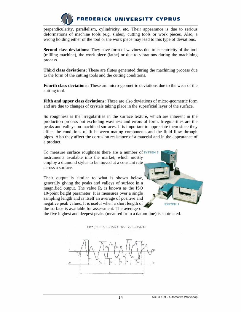
To measure surface roughness there are a number of instruments available into the market, which mostly employ a diamond stylus to be moved at a constant rate across a surface.
Their output is similar to what is shown below, generally giving the peaks and valleys of surface in a magnified output. The value Rz is known as the ISO 10-point height parameter. It is measures over a single sampling length and is itself an average of positive and negative peak values. It is useful when a short length of the surface is available for assessment. The average of the five highest and deepest peaks (meaured from a datum line) is subtracted.

AUTO 109 - Automotive Workshop 15
Surfaces below were obtain by cutting or deformation and their roughness is classified according to standard DIN 3141. (From left to right: quality increases)

AUTO 109 - Automotive Workshop 16
TOLERANCES
- Definitions
- Classes of fit
- Methods of tolerancing
- Exercise
Classes of fit and Toleranced dimensioning Accuracy of fit
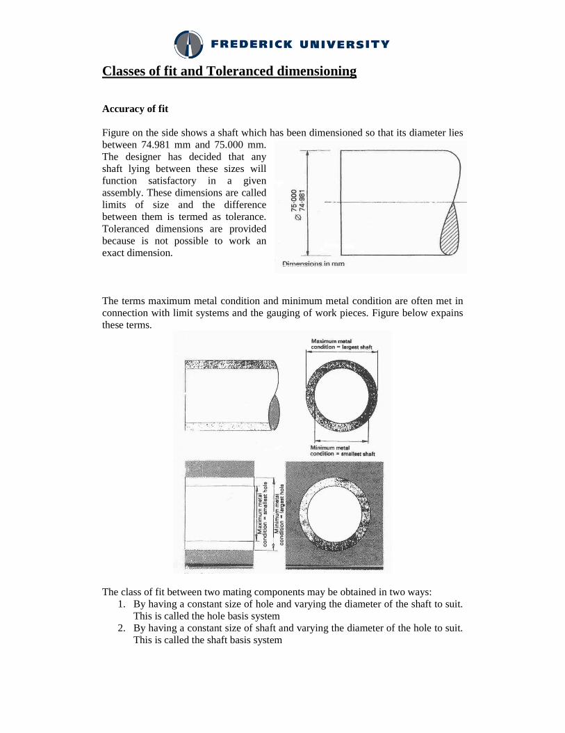
Figure on the side shows a shaft which has been dimensioned so that its diameter lies between 74.981 mm and 75.000 mm. The designer has decided that any shaft lying between these sizes will function satisfactory in a given assembly. These dimensions are called limits of size and the difference between them is termed as tolerance. Toleranced dimensions are provided because is not possible to work an exact dimension.
The terms maximum metal condition and minimum metal condition are often met in connection with limit systems and the gauging of work pieces. Figure below expains these terms.
The class of fit between two mating components may be obtained in two ways: 1. By having a constant size of hole and varying the diameter of the shaft to suit.
This is called the hole basis system 2. By having a constant size of shaft and varying the diameter of the hole to suit.
This is called the shaft basis system
AUTO 109 - Automotive Workshop 18
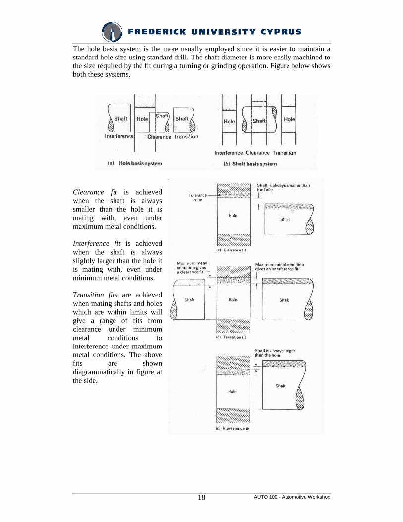
The hole basis system is the more usually employed since it is easier to maintain a standard hole size using standard drill. The shaft diameter is more easily machined to the size required by the fit during a turning or grinding operation. Figure below shows both these systems.
Clearance fit is achieved when the shaft is always smaller than the hole it is mating with, even under maximum metal conditions.
Interference fit is achieved when the shaft is always slightly larger than the hole it is mating with, even under minimum metal conditions.
Transition fits are achieved when mating shafts and holes which are within limits will give a range of fits from clearance under minimum metal conditions to interference under maximum metal conditions. The above fits are shown diagrammatically in figure at the side.
AUTO 109 - Automotive Workshop 19
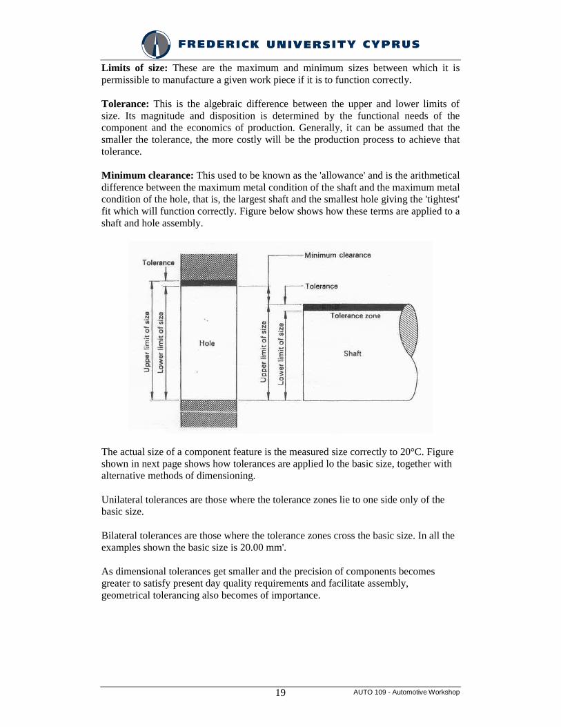
Limits of size: These are the maximum and minimum sizes between which it is permissible to manufacture a given work piece if it is to function correctly.
Tolerance: This is the algebraic difference between the upper and lower limits of size. Its magnitude and disposition is determined by the functional needs of the component and the economics of production. Generally, it can be assumed that the smaller the tolerance, the more costly will be the production process to achieve that tolerance.
Minimum clearance: This used to be known as the 'allowance' and is the arithmetical difference between the maximum metal condition of the shaft and the maximum metal condition of the hole, that is, the largest shaft and the smallest hole giving the 'tightest' fit which will function correctly. Figure below shows how these terms are applied to a shaft and hole assembly.
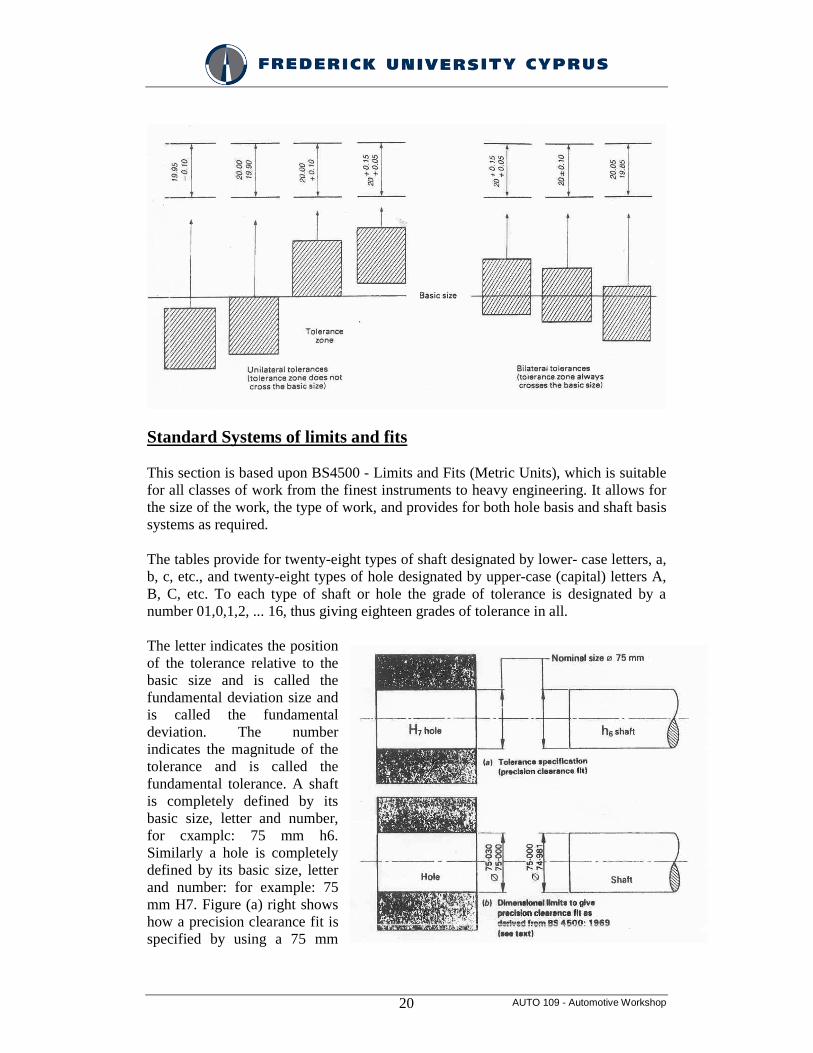
The actual size of a component feature is the measured size correctly to 20°C. Figure shown in next page shows how tolerances are applied lo the basic size, together with alternative methods of dimensioning.
Unilateral tolerances are those where the tolerance zones lie to one side only of the basic size.
Bilateral tolerances are those where the tolerance zones cross the basic size. In all the examples shown the basic size is 20.00 mm'.
As dimensional tolerances get smaller and the precision of components becomes greater to satisfy present day quality requirements and facilitate assembly, geometrical tolerancing also becomes of importance.
AUTO 109 - Automotive Workshop 20
Standard Systems of limits and fits
This section is based upon BS4500 - Limits and Fits (Metric Units), which is suitable for all classes of work from the finest instruments to heavy engineering. It allows for the size of the work, the type of work, and provides for both hole basis and shaft basis systems as required.
The tables provide for twenty-eight types of shaft designated by lower- case letters, a, b, c, etc., and twenty-eight types of hole designated by upper-case (capital) letters A, B, C, etc. To each type of shaft or hole the grade of tolerance is designated by a number 01,0,1,2, ... 16, thus giving eighteen grades of tolerance in all.
The letter indicates the position of the tolerance relative to the basic size and is called the fundamental deviation size and is called the fundamental deviation. The number indicates the magnitude of the tolerance and is called the fundamental tolerance. A shaft is completely defined by its basic size, letter and number, for cxamplc: 75 mm h6. Similarly a hole is completely defined by its basic size, letter and number: for example: 75 mm H7. Figure (a) right shows how a precision clearance fit is specified by using a 75 mm
AUTO 109 - Automotive Workshop 21
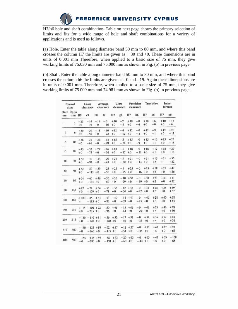
H7/h6 hole and shaft combination. Table on next page shows the primary selection of limits and fits for a wide range of hole and shaft combinations for a variety of applications and is used as follows.
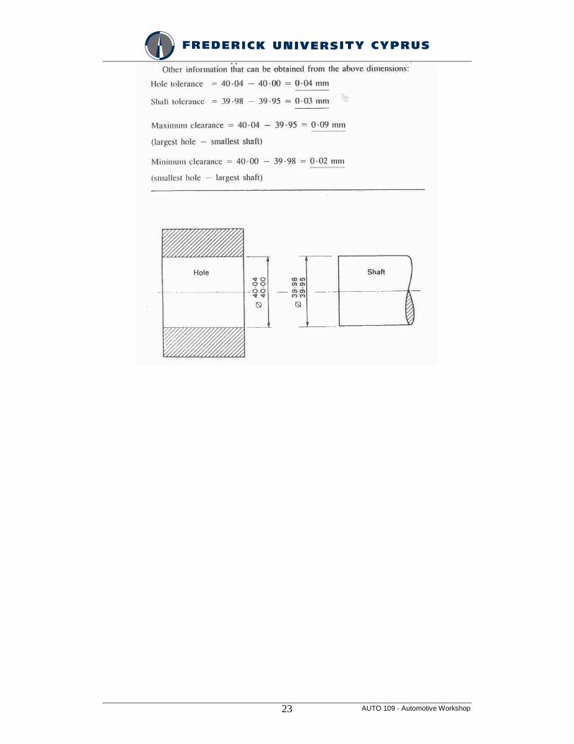
(a) Hole. Enter the table along diameter band 50 mm to 80 mm, and where this band crosses the column H7 the limits are given as + 30 and +0. These dimensions are in units of 0.001 mm Therefore, when applied to a basic size of 75 mm, they give working limits of 75.030 mm and 75.000 mm as shown in Fig. (b) in previous page.
(b) Shaft. Enter the table along diameter band 50 mm to 80 mm, and where this band crosses the column h6 the limits are given as - 0 and - 19. Again these dimensions are in units of 0.001 mm. Therefore, when applied to a basic size of 75 mm, they give working limits of 75.000 mm and 74.981 mm as shown in Fig. (b) in previous page.
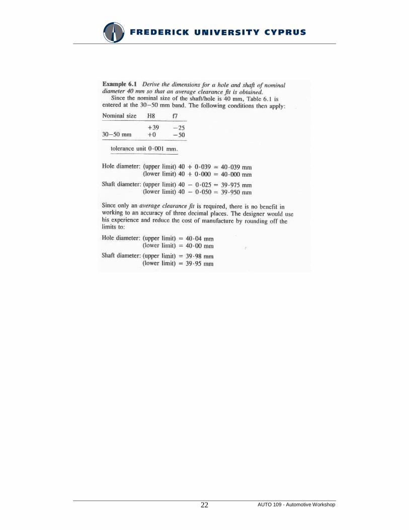
AUTO 109 - Automotive Workshop 22
AUTO 109 - Automotive Workshop 23
AUTO 109 - Automotive Workshop 24
ENGINE
1)
- Engine Checks
- Cylinder Head
2)
- Engine Block
- Lubricating System
3)
- Oil Consumption
- Cooling System
4)
- Intake System
- Exhaust System
AUTO 109 - Automotive Workshop 25
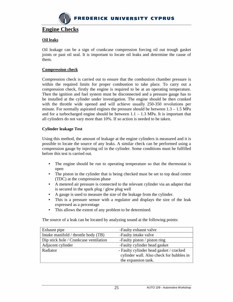
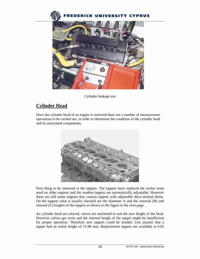
Engine Checks Oil leaks Oil leakage can be a sign of crankcase compression forcing oil out trough gasket joints or past oil seal. It is important to locate oil leaks and determine the cause of them. Compression check Compression check is carried out to ensure that the combustion chamber pressure is within the required limits for proper combustion to take place. To carry out a compression check, firstly the engine is required to be at an operating temperature. Then the ignition and fuel system must be disconnected and a pressure gauge has to be installed at the cylinder under investigation. The engine should be then cranked with the throttle wide opened and will achieve usually 250-350 revolutions per minute. For normally aspirated engines the pressure should be between 1.3 – 1.5 MPa and for a turbocharged engine should be between 1.1 – 1.3 MPa. It is important that all cylinders do not vary more than 10%. If so action is needed to be taken. Cylinder leakage Test Using this method, the amount of leakage at the engine cylinders is measured and it is possible to locate the source of any leaks. A similar check can be performed using a compression gauge by injecting oil in the cylinder. Some conditions must be fulfilled before this test is carried out.
• The engine should be run to operating temperature so that the thermostat is open
• The piston in the cylinder that is being checked must be set to top dead centre (TDC) at the compression phase
• A metered air pressure is connected to the relevant cylinder via an adapter that is secured in the spark plug / glow plug well
• A gauge is used to measure the size of the leakage from the cylinder. • This is a pressure sensor with a regulator and displays the size of the leak
expressed as a percentage • This allows the extent of any problem to be determined.
The source of a leak can be located by analyzing sound at the following points: Exhaust pipe -Faulty exhaust valve Intake manifold / throttle body (TB) -Faulty intake valve Dip stick hole / Crankcase ventilation -Faulty piston / piston ring Adjacent cylinder -Faulty cylinder head gasket Radiator - Faulty cylinder head gasket / cracked cylinder wall. Also check for bubbles in the expansion tank.
AUTO 109 - Automotive Workshop 26
Cylinder leakage test
Cylinder Head Once the cylinder head of an engine is removed there are a number of measurement operations to be carried out, in order to determine the condition of the cylinder head and its associated components.
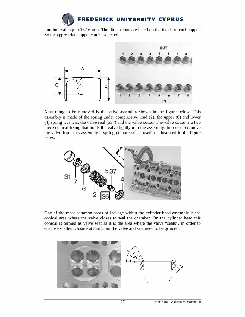
First thing to be removed is the tappets. The tappets have replaced the rocker arms used on older engines and the modern tappets are automatically adjustable. However there are still some engines that contain tappets with adjustable discs termed shims. On the tappets what is usually checked are the diameter A and the external (B) and internal (C) heights of the tappets as shown in the figure in the next page. As cylinder head are refaced, valves are machined to suit the new height of the head. However valves get worn and the internal height of the tappet might be insufficient for proper operation. Therefore new tappets could be needed. Lets assume that a tappet had an initial height of 15.96 mm. Replacement tappets are available at 0.02
AUTO 109 - Automotive Workshop 27
mm intervals up to 16.16 mm. The dimensions are listed on the inside of each tappet. So the appropriate tappet can be selected.
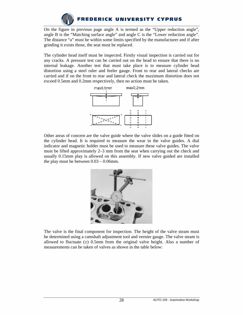
Next thing to be removed is the valve assembly shown in the figure below. This assembly is made of the spring under compressive load (2), the upper (6) and lower (4) spring washers, the valve seal (537) and the valve cotter. The valve cotter is a two piece conical fixing that holds the valve tightly into the assembly. In order to remove the valve from this assembly a spring compressor is used as illustrated in the figure below.
One of the most common areas of leakage within the cylinder head assembly is the conical area where the valve closes to seal the chamber. On the cylinder head this conical is termed as valve seat as it is the area where the valve “seats”. In order to ensure excellent closure at that point the valve and seat need to be grinded.
AUTO 109 - Automotive Workshop 28
On the figure in previous page angle A is termed as the “Upper reduction angle”, angle B is the “Matching surface angle” and angle C is the “Lower reduction angle”. The distance “a” must be within some limits specified by the manufacturer and if after grinding it exists those, the seat must be replaced. The cylinder head itself must be inspected. Firstly visual inspection is carried out for any cracks. A pressure test can be carried out on the head to ensure that there is no internal leakage. Another test that must take place is to measure cylinder head distortion using a steel ruler and feeler gauge. Front to rear and lateral checks are carried and if on the front to rear and lateral check the maximum distortion does not exceed 0.5mm and 0.2mm respectively, then no action must be taken.
Other areas of concern are the valve guide where the valve slides on a guide fitted on the cylinder head. It is required to measure the wear in the valve guides. A dial indicator and magnetic holder must be used to measure these valve guides. The valve must be lifted approximately 2–3 mm from the seat when carrying out the check and usually 0.15mm play is allowed on this assembly. If new valve guided are installed the play must be between 0.03 – 0.06mm.
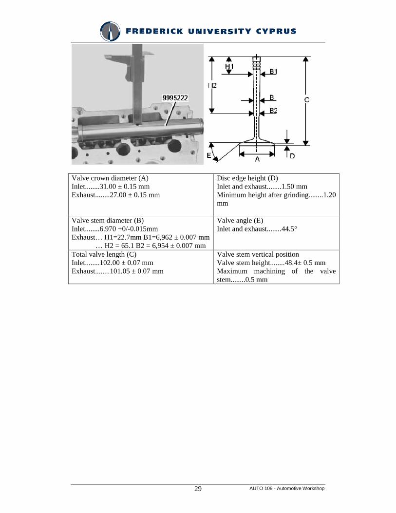
The valve is the final component for inspection. The height of the valve steam must be determined using a camshaft adjustment tool and vernier gauge. The valve steam is allowed to fluctuate (±) 0.5mm from the original valve height. Also a number of measurements can be taken of valves as shown in the table below:
AUTO 109 - Automotive Workshop 29
Valve crown diameter (A) Inlet........31.00 ± 0.15 mm Exhaust........27.00 ± 0.15 mm
Disc edge height (D) Inlet and exhaust........1.50 mm Minimum height after grinding........1.20 mm
Valve stem diameter (B) Inlet........6.970 +0/-0.015mm Exhaust… H1=22.7mm B1=6,962 ± 0.007 mm … H2 = 65.1 B2 = 6,954 ± 0.007 mm
Valve angle (E) Inlet and exhaust........44.5°
Total valve length (C) Inlet........102.00 ± 0.07 mm Exhaust........101.05 ± 0.07 mm
Valve stem vertical position Valve stem height........48.4± 0.5 mm Maximum machining of the valve stem........0.5 mm
AUTO 109 - Automotive Workshop 30
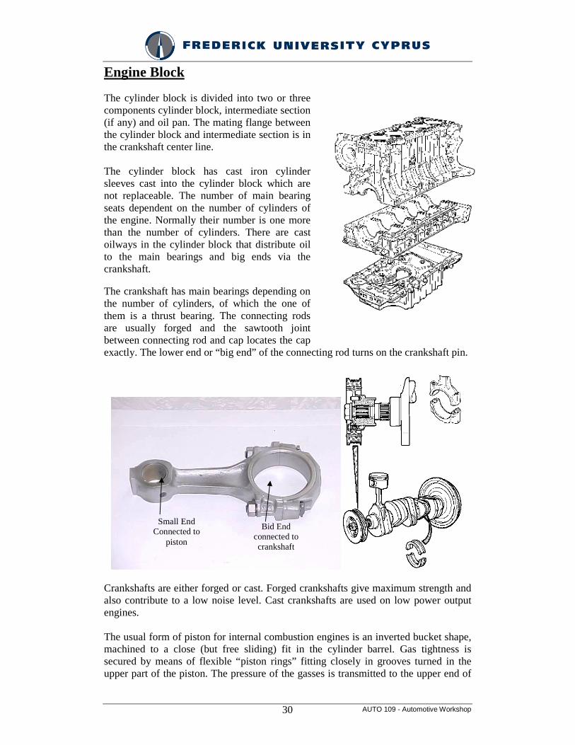
Engine Block The cylinder block is divided into two or three components cylinder block, intermediate section (if any) and oil pan. The mating flange between the cylinder block and intermediate section is in the crankshaft center line. The cylinder block has cast iron cylinder sleeves cast into the cylinder block which are not replaceable. The number of main bearing seats dependent on the number of cylinders of the engine. Normally their number is one more than the number of cylinders. There are cast oilways in the cylinder block that distribute oil to the main bearings and big ends via the crankshaft. The crankshaft has main bearings depending on the number of cylinders, of which the one of them is a thrust bearing. The connecting rods are usually forged and the sawtooth joint between connecting rod and cap locates the cap exactly. The lower end or “big end” of the connecting rod turns on the crankshaft pin.
Crankshafts are either forged or cast. Forged crankshafts give maximum strength and also contribute to a low noise level. Cast crankshafts are used on low power output engines. The usual form of piston for internal combustion engines is an inverted bucket shape, machined to a close (but free sliding) fit in the cylinder barrel. Gas tightness is secured by means of flexible “piston rings” fitting closely in grooves turned in the upper part of the piston. The pressure of the gasses is transmitted to the upper end of
Small End Connected to
piston
Bid End connected to crankshaft
AUTO 109 - Automotive Workshop 31
the connecting rod through the “gudgeon pin” on which the “small end” of the connecting rod is free to swing.
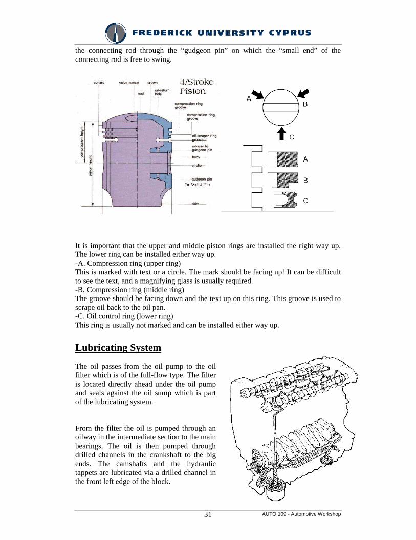
It is important that the upper and middle piston rings are installed the right way up. The lower ring can be installed either way up. -A. Compression ring (upper ring) This is marked with text or a circle. The mark should be facing up! It can be difficult to see the text, and a magnifying glass is usually required. -B. Compression ring (middle ring) The groove should be facing down and the text up on this ring. This groove is used to scrape oil back to the oil pan. -C. Oil control ring (lower ring) This ring is usually not marked and can be installed either way up.
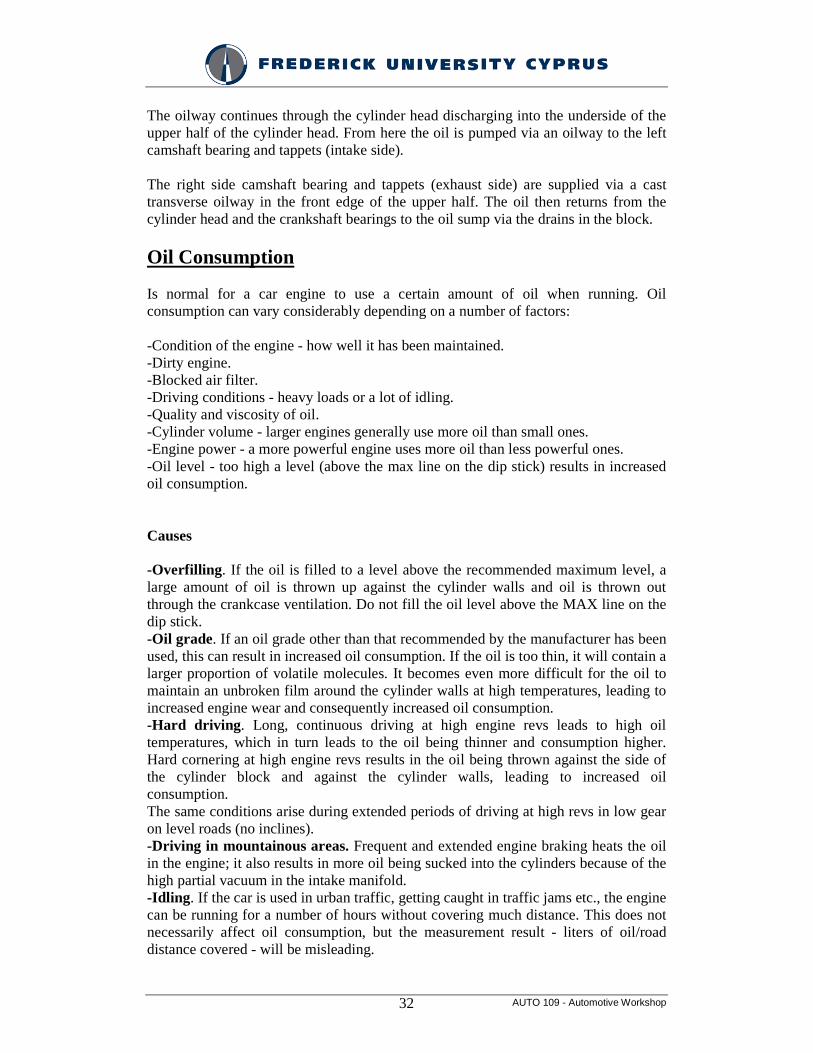
Lubricating System The oil passes from the oil pump to the oil filter which is of the full-flow type. The filter is located directly ahead under the oil pump and seals against the oil sump which is part of the lubricating system. From the filter the oil is pumped through an oilway in the intermediate section to the main bearings. The oil is then pumped through drilled channels in the crankshaft to the big ends. The camshafts and the hydraulic tappets are lubricated via a drilled channel in the front left edge of the block.
AUTO 109 - Automotive Workshop 32
The oilway continues through the cylinder head discharging into the underside of the upper half of the cylinder head. From here the oil is pumped via an oilway to the left camshaft bearing and tappets (intake side). The right side camshaft bearing and tappets (exhaust side) are supplied via a cast transverse oilway in the front edge of the upper half. The oil then returns from the cylinder head and the crankshaft bearings to the oil sump via the drains in the block.
Oil Consumption Is normal for a car engine to use a certain amount of oil when running. Oil consumption can vary considerably depending on a number of factors: -Condition of the engine - how well it has been maintained. -Dirty engine. -Blocked air filter. -Driving conditions - heavy loads or a lot of idling. -Quality and viscosity of oil. -Cylinder volume - larger engines generally use more oil than small ones. -Engine power - a more powerful engine uses more oil than less powerful ones. -Oil level - too high a level (above the max line on the dip stick) results in increased oil consumption. Causes -Overfilling. If the oil is filled to a level above the recommended maximum level, a large amount of oil is thrown up against the cylinder walls and oil is thrown out through the crankcase ventilation. Do not fill the oil level above the MAX line on the dip stick. -Oil grade. If an oil grade other than that recommended by the manufacturer has been used, this can result in increased oil consumption. If the oil is too thin, it will contain a larger proportion of volatile molecules. It becomes even more difficult for the oil to maintain an unbroken film around the cylinder walls at high temperatures, leading to increased engine wear and consequently increased oil consumption. -Hard driving. Long, continuous driving at high engine revs leads to high oil temperatures, which in turn leads to the oil being thinner and consumption higher. Hard cornering at high engine revs results in the oil being thrown against the side of the cylinder block and against the cylinder walls, leading to increased oil consumption. The same conditions arise during extended periods of driving at high revs in low gear on level roads (no inclines). -Driving in mountainous areas. Frequent and extended engine braking heats the oil in the engine; it also results in more oil being sucked into the cylinders because of the high partial vacuum in the intake manifold. -Idling. If the car is used in urban traffic, getting caught in traffic jams etc., the engine can be running for a number of hours without covering much distance. This does not necessarily affect oil consumption, but the measurement result - liters of oil/road distance covered - will be misleading.
AUTO 109 - Automotive Workshop 33
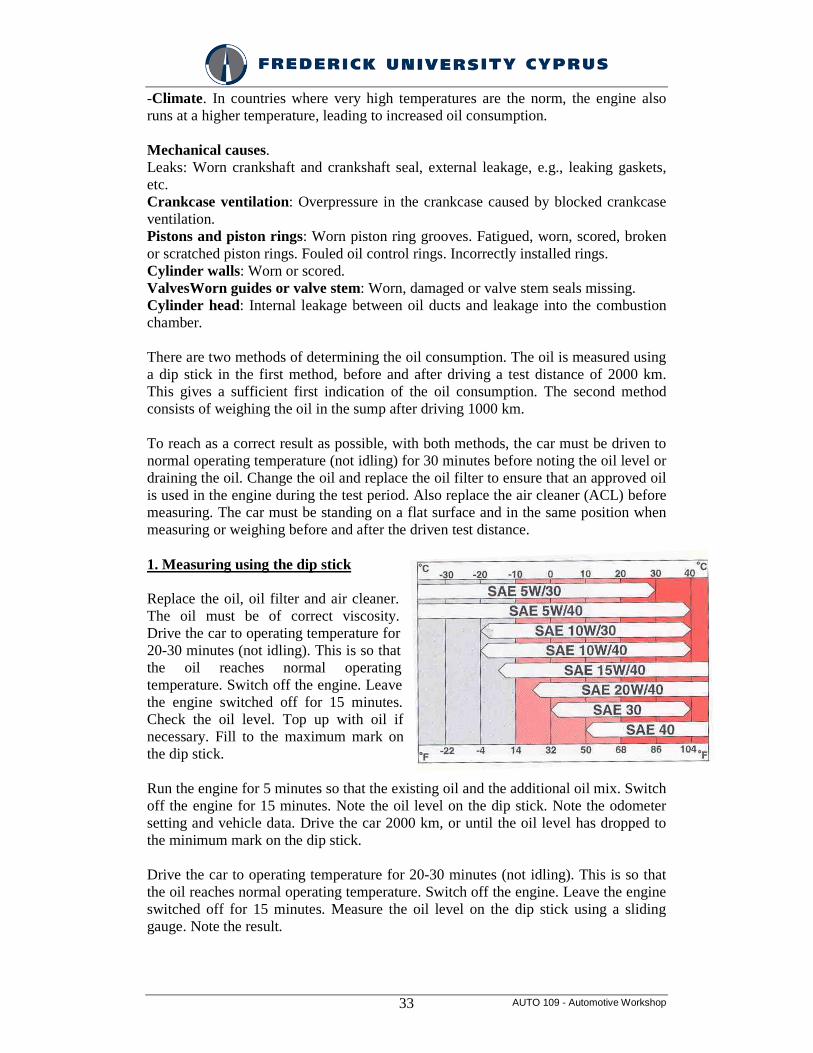
-Climate. In countries where very high temperatures are the norm, the engine also runs at a higher temperature, leading to increased oil consumption. Mechanical causes. Leaks: Worn crankshaft and crankshaft seal, external leakage, e.g., leaking gaskets, etc. Crankcase ventilation: Overpressure in the crankcase caused by blocked crankcase ventilation. Pistons and piston rings: Worn piston ring grooves. Fatigued, worn, scored, broken or scratched piston rings. Fouled oil control rings. Incorrectly installed rings. Cylinder walls: Worn or scored. ValvesWorn guides or valve stem: Worn, damaged or valve stem seals missing. Cylinder head: Internal leakage between oil ducts and leakage into the combustion chamber. There are two methods of determining the oil consumption. The oil is measured using a dip stick in the first method, before and after driving a test distance of 2000 km. This gives a sufficient first indication of the oil consumption. The second method consists of weighing the oil in the sump after driving 1000 km. To reach as a correct result as possible, with both methods, the car must be driven to normal operating temperature (not idling) for 30 minutes before noting the oil level or draining the oil. Change the oil and replace the oil filter to ensure that an approved oil is used in the engine during the test period. Also replace the air cleaner (ACL) before measuring. The car must be standing on a flat surface and in the same position when measuring or weighing before and after the driven test distance. 1. Measuring using the dip stick Replace the oil, oil filter and air cleaner. The oil must be of correct viscosity. Drive the car to operating temperature for 20-30 minutes (not idling). This is so that the oil reaches normal operating temperature. Switch off the engine. Leave the engine switched off for 15 minutes. Check the oil level. Top up with oil if necessary. Fill to the maximum mark on the dip stick. Run the engine for 5 minutes so that the existing oil and the additional oil mix. Switch off the engine for 15 minutes. Note the oil level on the dip stick. Note the odometer setting and vehicle data. Drive the car 2000 km, or until the oil level has dropped to the minimum mark on the dip stick. Drive the car to operating temperature for 20-30 minutes (not idling). This is so that the oil reaches normal operating temperature. Switch off the engine. Leave the engine switched off for 15 minutes. Measure the oil level on the dip stick using a sliding gauge. Note the result.
AUTO 109 - Automotive Workshop 34
2. Weighing Drive the car to operating temperature for 20-30 minutes (not idling). This is so that the oil reaches operating temperature. Drain the oil from the oil trough for 15 minutes. A large amount of oil is collected in the cylinder head when the car is running. This factor, together with the design of the splash guard in the sump, means that it takes a long time for the oil to drain out of the engine. The oil must not be reused. Replace the oil filter and air cleaner. Fill with the specified amount of approved engine oil. Drive the car to operating temperature for 20-30 minutes (not idling). This is so that the oil reaches normal operating temperature and the oil filter fills. Carefully weigh an empty clean container (± 1 gram). Drain the oil from the oil trough into the container for 15 minutes. Carefully weigh the container and oil. Fill the engine with the weighed oil. Ensure that as much oil as possible leaves the container. Weigh the empty container. The container may weigh more than it did the first time due to the remaining oil film. The difference in weight is taken from the weighed oil weight. Note the oil weight odometer setting and vehicle data. Drive the car 1000 km, or until the oil level has dropped to the minimum mark on the dip stick. Ensure that the engine is at normal operating temperature. Drive to normal operating temperature if necessary for 20–30 minutes (not idling). Carefully weigh an empty clean container (± 1 gram). Drain the oil from the oil trough into the container for 15 minutes. Carefully weigh the oil and container. Deduct the weight of the container. If abnormal oil consumption is discovered when measuring, the engine needs to be remedied as follows. Corrective action for high oil consumption Conditions If the engine consumes more than 0.4 litres of oil every 1000 km, the following checks must be carried out to check whether the oil consumption problem is in the cylinder head, crankcase ventilation or piston ring and sleeve surface. Check Remove the intake manifold. Check to see if there is an oil film or drops of oil in the cylinder head intake passage and/or oil on the valve stem and top of the valve crown. Conclusions If there is not an abnormally large amount of oil in the intake passage and valves and the oil consumption gradually, from being acceptable, begins to quickly increase, or consumption is between 0.30-0.80 litres per 1000 km, the problem is in the piston, piston ring or cylinder sleeve surface.
AUTO 109 - Automotive Workshop 35
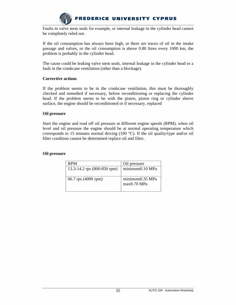
Faults in valve stem seals for example, or internal leakage in the cylinder head cannot be completely ruled out. If the oil consumption has always been high, or there are traces of oil in the intake passage and valves, or the oil consumption is above 0.80 litres every 1000 km, the problem is probably in the cylinder head. The cause could be leaking valve stem seals, internal leakage in the cylinder head or a fault in the crankcase ventilation (other than a blockage). Corrective actions If the problem seems to be in the crankcase ventilation, this must be thoroughly checked and remedied if necessary, before reconditioning or replacing the cylinder head. If the problem seems to be with the piston, piston ring or cylinder sleeve surface, the engine should be reconditioned or if necessary, replaced Oil pressure Start the engine and read off oil pressure at different engine speeds (RPM), when oil level and oil pressure the engine should be at normal operating temperature which corresponds to 15 minutes normal driving (100 °C). If the oil quality/type and/or oil filter condition cannot be determined replace oil and filter. Oil pressure
RPM Oil pressure 13.3-14.2 rps (800-850 rpm) minimum0.10 MPa
66.7 rps (4000 rpm) minimum0.35 MPa
max0.70 MPa
AUTO 109 - Automotive Workshop 36
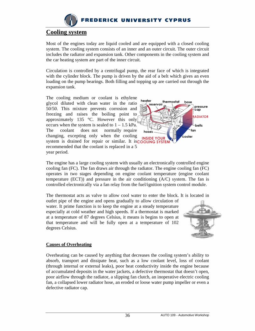
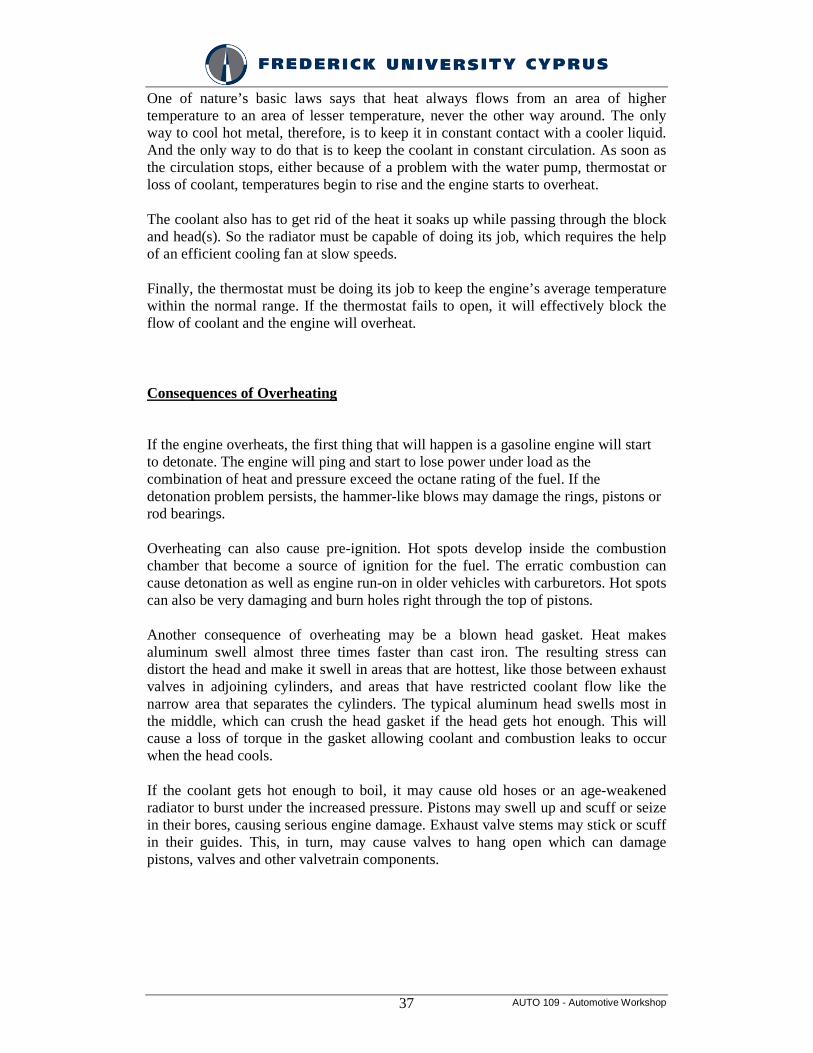
Cooling system Most of the engines today are liquid cooled and are equipped with a closed cooling system. The cooling system consists of an inner and an outer circuit. The outer circuit includes the radiator and expansion tank. Other components in the cooling system and the car heating system are part of the inner circuit. Circulation is controlled by a centrifugal pump, the rear face of which is integrated with the cylinder block. The pump is driven by the aid of a belt which gives an even loading on the pump bearings. Both filling and topping up are carried out through the expansion tank. The cooling medium or coolant is ethylene glycol diluted with clean water in the ratio 50/50. This mixture prevents corrosion and freezing and raises the boiling point to approximately 135 °C. However this only occurs when the system is sealed to 1 – 1.5 kPa. The coolant does not normally require changing, excepting only when the cooling system is drained for repair or similar. It is recommended that the coolant is replaced in a 5 year period. The engine has a large cooling system with usually an electronically controlled engine cooling fan (FC). The fan draws air through the radiator. The engine cooling fan (FC) operates in two stages depending on engine coolant temperature (engine coolant temperature (ECT)) and pressure in the air conditioning (A/C) system. The fan is controlled electronically via a fan relay from the fuel/ignition system control module. The thermostat acts as valve to allow cool water to enter the block. It is located in outlet pipe of the engine and opens gradually to allow circulation of water. It prime function is to keep the engine at a steady temperature especially at cold weather and high speeds. If a thermostat is marked at a temperature of 87 degrees Celsius, it means is begins to open at that temperature and will be fully open at a temperature of 102 degrees Celsius.
Causes of Overheating
Overheating can be caused by anything that decreases the cooling system’s ability to absorb, transport and dissipate heat, such as a low coolant level, loss of coolant (through internal or external leaks), poor heat conductivity inside the engine because of accumulated deposits in the water jackets, a defective thermostat that doesn’t open, poor airflow through the radiator, a slipping fan clutch, an inoperative electric cooling fan, a collapsed lower radiator hose, an eroded or loose water pump impeller or even a defective radiator cap.
AUTO 109 - Automotive Workshop 37
One of nature’s basic laws says that heat always flows from an area of higher temperature to an area of lesser temperature, never the other way around. The only way to cool hot metal, therefore, is to keep it in constant contact with a cooler liquid. And the only way to do that is to keep the coolant in constant circulation. As soon as the circulation stops, either because of a problem with the water pump, thermostat or loss of coolant, temperatures begin to rise and the engine starts to overheat.
The coolant also has to get rid of the heat it soaks up while passing through the block and head(s). So the radiator must be capable of doing its job, which requires the help of an efficient cooling fan at slow speeds.
Finally, the thermostat must be doing its job to keep the engine’s average temperature within the normal range. If the thermostat fails to open, it will effectively block the flow of coolant and the engine will overheat.
Consequences of Overheating
If the engine overheats, the first thing that will happen is a gasoline engine will start to detonate. The engine will ping and start to lose power under load as the combination of heat and pressure exceed the octane rating of the fuel. If the detonation problem persists, the hammer-like blows may damage the rings, pistons or rod bearings.
Overheating can also cause pre-ignition. Hot spots develop inside the combustion chamber that become a source of ignition for the fuel. The erratic combustion can cause detonation as well as engine run-on in older vehicles with carburetors. Hot spots can also be very damaging and burn holes right through the top of pistons.
Another consequence of overheating may be a blown head gasket. Heat makes aluminum swell almost three times faster than cast iron. The resulting stress can distort the head and make it swell in areas that are hottest, like those between exhaust valves in adjoining cylinders, and areas that have restricted coolant flow like the narrow area that separates the cylinders. The typical aluminum head swells most in the middle, which can crush the head gasket if the head gets hot enough. This will cause a loss of torque in the gasket allowing coolant and combustion leaks to occur when the head cools.
If the coolant gets hot enough to boil, it may cause old hoses or an age-weakened radiator to burst under the increased pressure. Pistons may swell up and scuff or seize in their bores, causing serious engine damage. Exhaust valve stems may stick or scuff in their guides. This, in turn, may cause valves to hang open which can damage pistons, valves and other valvetrain components.
AUTO 109 - Automotive Workshop 38
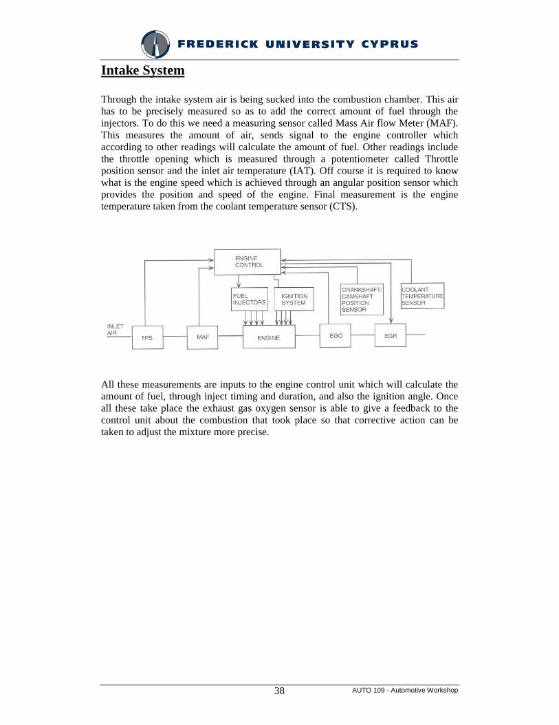
Intake System Through the intake system air is being sucked into the combustion chamber. This air has to be precisely measured so as to add the correct amount of fuel through the injectors. To do this we need a measuring sensor called Mass Air flow Meter (MAF). This measures the amount of air, sends signal to the engine controller which according to other readings will calculate the amount of fuel. Other readings include the throttle opening which is measured through a potentiometer called Throttle position sensor and the inlet air temperature (IAT). Off course it is required to know what is the engine speed which is achieved through an angular position sensor which provides the position and speed of the engine. Final measurement is the engine temperature taken from the coolant temperature sensor (CTS). All these measurements are inputs to the engine control unit which will calculate the amount of fuel, through inject timing and duration, and also the ignition angle. Once all these take place the exhaust gas oxygen sensor is able to give a feedback to the control unit about the combustion that took place so that corrective action can be taken to adjust the mixture more precise.
AUTO 109 - Automotive Workshop 39
Exhaust System Pollutants
The engine exhaust consists of the products of combustion of the air and gasoline mixture. Gasoline is a mixture of chemical compounds that are called hydrocarbons. This name is derived from the chemical formation of the various gasoline compounds, each of which is a chemical union of hydrogen (H) and carbon (C) in various proportions. Gasoline also contains natural impurities as well as chemicals added by the refiner. All of these can produce undesirable exhaust elements.
During the combustion process, the carbon and hydrogen combine with oxygen from the air, releasing heat energy and forming various chemical compounds. If the combustion were perfect, the exhaust gases would consist only of carbon dioxide (CO2) and water (H2O), neither of which is considered harmful to human health in the atmosphere. In fact, both are present in a human's breath.
Unfortunately, the combustion of the SI engine is not perfect. In addition to the CO2 and H2O, the exhaust contains amounts of carbon monoxide (CO), oxides of nitrogen (chemical unions of nitrogen and oxygen that are denoted NO.), unburned hydrocarbons (HC), oxides of sulfur, and other compounds. Some of the exhaust constitUents are considered harmful and have come under the control of the federal government. The exhaust emissions controlled by government standards are CO, HC, and NOx
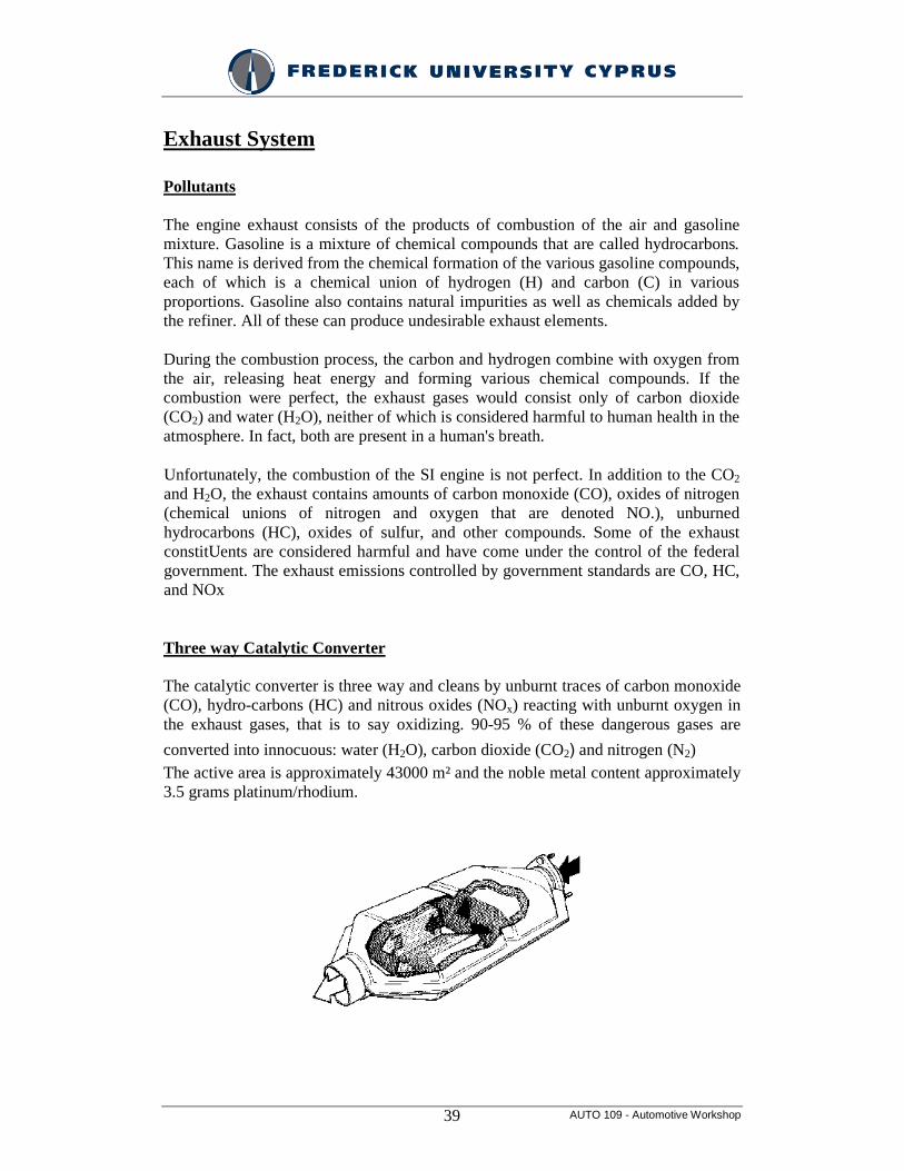
Three way Catalytic Converter The catalytic converter is three way and cleans by unburnt traces of carbon monoxide (CO), hydro-carbons (HC) and nitrous oxides (NOx) reacting with unburnt oxygen in the exhaust gases, that is to say oxidizing. 90-95 % of these dangerous gases are
converted into innocuous: water (H2O), carbon dioxide (CO2) and nitrogen (N2) The active area is approximately 43000 m² and the noble metal content approximately 3.5 grams platinum/rhodium.
AUTO 109 - Automotive Workshop 40
Effect of Air/Fuel ratio on performance
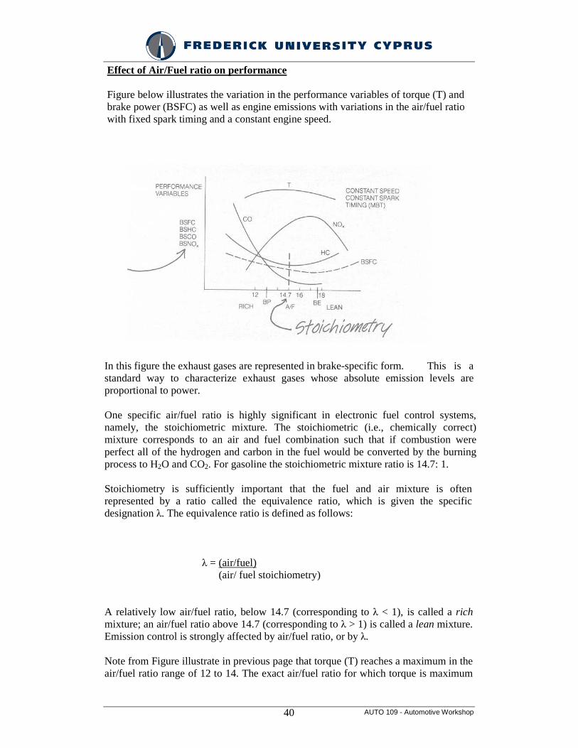
Figure below illustrates the variation in the performance variables of torque (T) and brake power (BSFC) as well as engine emissions with variations in the air/fuel ratio with fixed spark timing and a constant engine speed.
In this figure the exhaust gases are represented in brake-specific form. This is a standard way to characterize exhaust gases whose absolute emission levels are proportional to power.
One specific air/fuel ratio is highly significant in electronic fuel control systems, namely, the stoichiometric mixture. The stoichiometric (i.e., chemically correct) mixture corresponds to an air and fuel combination such that if combustion were perfect all of the hydrogen and carbon in the fuel would be converted by the burning process to H2O and CO2. For gasoline the stoichiometric mixture ratio is 14.7: 1.
Stoichiometry is sufficiently important that the fuel and air mixture is often represented by a ratio called the equivalence ratio, which is given the specific designation λ. The equivalence ratio is defined as follows:
λ = (air/fuel) (air/ fuel stoichiometry)
A relatively low air/fuel ratio, below 14.7 (corresponding to λ < 1), is called a rich mixture; an air/fuel ratio above 14.7 (corresponding to λ > 1) is called a lean mixture. Emission control is strongly affected by air/fuel ratio, or by λ.
Note from Figure illustrate in previous page that torque (T) reaches a maximum in the air/fuel ratio range of 12 to 14. The exact air/fuel ratio for which torque is maximum
AUTO 109 - Automotive Workshop 41
depends on the engine configuration, engine speed, and ignition timing.
Also note that the CO and unburned hydrocarbons tend to decrease sharply with increasing air/fuel ratios, as one might expect because there is relatively more oxygen available for combustion with lean mixtures than with rich mixtures.
Unfortunately for the purposes of controlling exhaust emissions, the NOx exhaust concentration increases with increasing air/fuel ratios. That is, there is no air/fuel ratio that simultaneously minimizes all regulated exhaust gases. However, by adding another control variable, the undesirable exhaust gas emission of NOx can be significantly reduced while maintaining a relatively high level of torque. This new control variable, exhaust gas recirculation (EGR), consists of recirculating a precisely controlled amount of exhaust gas into the intake.