Embed Size (px)
Citation preview

Next-Generation Production Environment Sensors
Series
ZN-PD-SAAir Particle Sensor
ZN-THX21-SAThermo-Humidity Station
ZN-DPX21-SADifferential Pressure Station
Make your entire production environment visibleMulti-point monitoring of environmental data and central control
Thermo-Humidity Station
Air Particle Sensor
Dust measurement type
Air Particle Sensor
Particle measurement type
Differential Pressure Station
Authorized Distributor:
In the interest of product improvement, specifications are subject to change without notice.
Cat. No. E411-E1-02Printed in Japan0513 (0611) (TA)
© OMRON Corporation 2011 All Rights Reserved.
OMRON Corporation Industrial Automation Company
OMRON ELECTRONICS LLCOne Commerce Drive Schaumburg,IL 60173-5302 U.S.A.Tel: (1) 847-843-7900/Fax: (1) 847-843-7787
Contact: www.ia.omron.comTokyo, JAPAN
OMRON ASIA PACIFIC PTE. LTD.No. 438A Alexandra Road # 05-05/08 (Lobby 2), Alexandra Technopark, Singapore 119967Tel: (65) 6835-3011/Fax: (65) 6835-2711
OMRON (CHINA) CO., LTD.Room 2211, Bank of China Tower, 200 Yin Cheng Zhong Road, PuDong New Area, Shanghai, 200120, ChinaTel: (86) 21-5037-2222/Fax: (86) 21-5037-2200
Regional HeadquartersOMRON EUROPE B.V.Sensor Business UnitCarl-Benz-Str. 4, D-71154 Nufringen, GermanyTel: (49) 7032-811-0/Fax: (49) 7032-811-199
Terms and Conditions AgreementRead and understand this catalog.
Please read and understand this catalog before purchasing the products. Please consult your OMRON representative if you have any questions or comments.
Warranties.
(a) Exclusive Warranty. Omron’s exclusive warranty is that the Products will be free from defects in materials and workmanship for a period of twelve months from the date of sale by Omron (or such other period expressed in writing by Omron). Omron disclaims all other warranties, express or implied.
(b) Limitations. OMRON MAKES NO WARRANTY OR REPRESENTATION, EXPRESS OR IMPLIED, ABOUT NON-INFRINGEMENT, MERCHANTABILITY OR FITNESS FOR A PARTICULAR PURPOSE OF THE PRODUCTS. BUYER ACKNOWLEDGES THAT IT ALONE HAS DETERMINED THAT THE PRODUCTS WILL SUITABLY MEET THE REQUIREMENTS OF THEIR INTENDED USE.
Omron further disclaims all warranties and responsibility of any type for claims or expenses based on infringement by the Products or otherwise of any intellectual property right. (c) Buyer Remedy. Omron’s sole obligation hereunder shall be, at Omron’s election, to (i) replace (in the form originally shipped with Buyer responsible for labor charges for removal or replacement thereof) the non-complying Product, (ii) repair the non-complying Product, or (iii) repay or credit Buyer an amount equal to the purchase price of the non-complying Product; provided that in no event shall Omron be responsible for warranty, repair, indemnity or any other claims or expenses regarding the Products unless Omron’s analysis confirms that the Products were properly handled, stored, installed and maintained and not subject to contamination, abuse, misuse or inappropriate modification. Return of any Products by Buyer must be approved in writing by Omron before shipment. Omron Companies shall not be liable for the suitability or unsuitability or the results from the use of Products in combination with any electrical or electronic components, circuits, system assemblies or any other materials or substances or environments. Any advice, recommendations or information given orally or in writing, are not to be construed as an amendment or addition to the above warranty.
See http://www.omron.com/global/ or contact your Omron representative for published information.
Limitation on Liability; Etc.
OMRON COMPANIES SHALL NOT BE LIABLE FOR SPECIAL, INDIRECT, INCIDENTAL, OR CONSEQUENTIAL DAMAGES, LOSS OF PROFITS OR PRODUCTION OR COMMERCIAL LOSS IN ANY WAY CONNECTED WITH THE PRODUCTS, WHETHER SUCH CLAIM IS BASED IN CONTRACT, WARRANTY, NEGLIGENCE OR STRICT LIABILITY.
Further, in no event shall liability of Omron Companies exceed the individual price of the Product on which liability is asserted.
Suitability of Use.
Omron Companies shall not be responsible for conformity with any standards, codes or regulations which apply to the combination of the Product in the Buyer’s application or use of the Product. At Buyer’s request, Omron will provide applicable third party certification documents identifying ratings and limitations of use which apply to the Product. This information by itself is not sufficient for a complete determination of the suitability of the Product in combination with the end product, machine, system, or other application or use. Buyer shall be solely responsible for determining appropriateness of the particular Product with respect to Buyer’s application, product or system. Buyer shall take application responsibility in all cases.
NEVER USE THE PRODUCT FOR AN APPLICATION INVOLVING SERIOUS RISK TO LIFE OR PROPERTY OR IN LARGE QUANTITIES WITHOUT ENSURING THAT THE SYSTEM AS A WHOLE HAS BEEN DESIGNED TO ADDRESS THE RISKS, AND THAT THE OMRON PRODUCT(S) IS PROPERLY RATED AND INSTALLED FOR THE INTENDED USE WITHIN THE OVERALL EQUIPMENT OR SYSTEM.
Programmable Products.
Omron Companies shall not be responsible for the user’s programming of a programmable Product, or any consequence thereof.
Performance Data.
Data presented in Omron Company websites, catalogs and other materials is provided as a guide for the user in determining suitability and does not constitute a warranty. It may represent the result of Omron’s test conditions, and the user must correlate it to actual application requirements. Actual performance is subject to the Omron’s Warranty and Limitations of Liability.
Change in Specifications.
Product specifications and accessories may be changed at any time based on improvements and other reasons. It is our practice to change part numbers when published ratings or features are changed, or when significant construction changes are made. However, some specifications of the Product may be changed without any notice. When in doubt, special part numbers may be assigned to fix or establish key specifications for your application. Please consult with your Omron’s representative at any time to confirm actual specifications of purchased Product.
Errors and Omissions.
Information presented by Omron Companies has been checked and is believed to be accurate; however, no responsibility is assumed for clerical, typographical or proofreading errors or omissions.
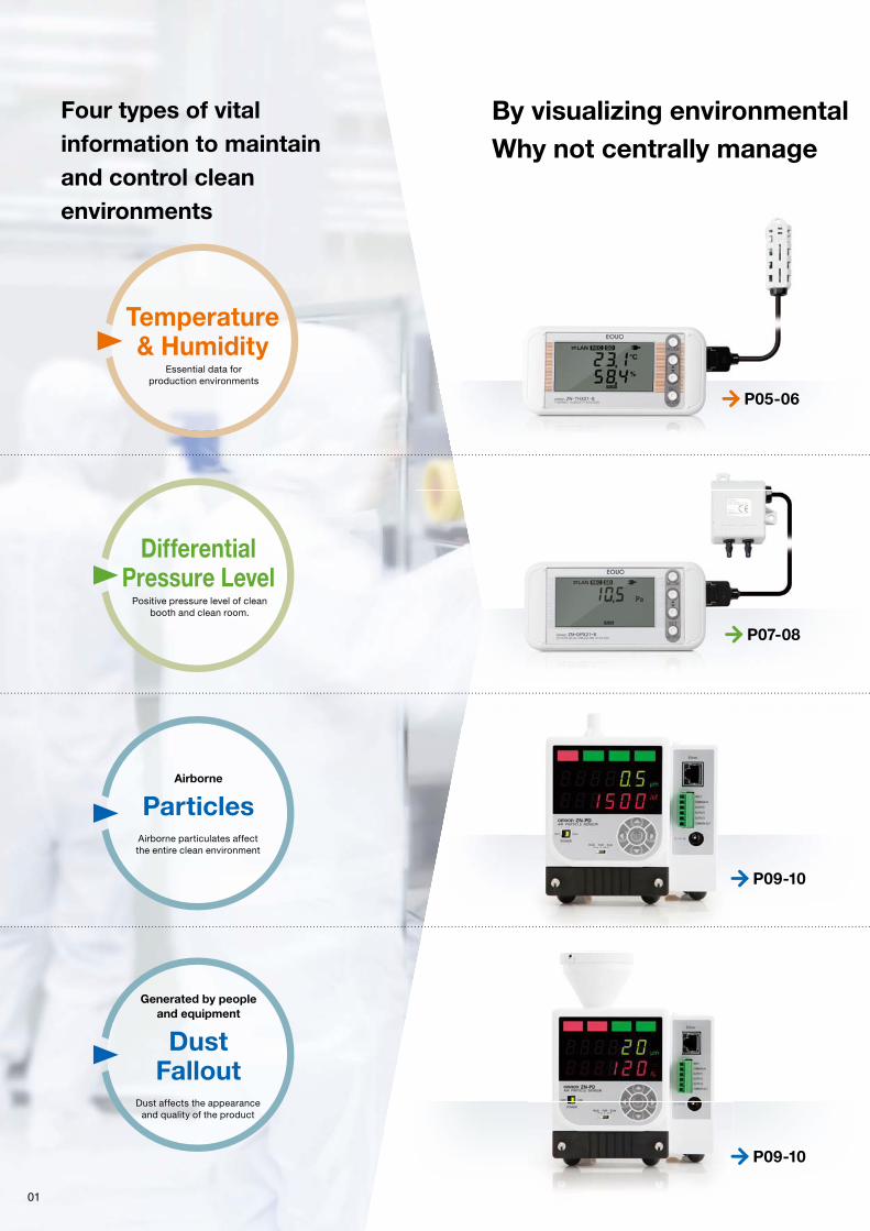
By visualizing environmental Why not centrally manage
Essential data for production environments
Airborne particulates affect the entire clean environment
Temperature& Humidity
Positive pressure level of clean booth and clean room.
DifferentialPressure Level
Airborne
Particles
Dust affects the appearance and quality of the product
Generated by peopleand equipment
DustFallout
01
P05-06
P07-08
P09-10
P09-10
Four types of vital information to maintain and control clean environments

by PC
by PLC
P11
Environmental Visualization Software
ZN-SW11-S
Clearly visualize multiple types of environmental information
Environmental changes can be tracked over time and by distribution
Easy network connection through Ethernet. Centralized management of measured data is possible immediately after installation, achieving low-cost operation. Also, data can be logged automatically at all times, reducing man-hours for measurement and labor costs. Easy-to-use GUI allows you to visualize the entire clean environment.
Option
New Ver.
Customers can construct their own unique production environment monitoring and control systems.
Recommendation: SYSMAC CS/CJ Series Ethernet unit
Note: Some conditions and limitations apply to PLC connection. Be sure to contact the OMRON Sales Department for details.
Centralized data management through a LAN network.
conditions, it’s easier to maintain and control clean environments.your measured data to improve quality and save energy?
Precision measurement of temperature and humidity
along manufacturing lines and around equipment.
Thermo-Humidity Station
02
-25 to 60°C (Accuracy: ±0.3°C) 0% to 99% (Accuracy: ±2.5%)
ZN-THX21-SA (Station)ZN-THS11-S (Sensor head)
Precision measurement of differential pressure
between inside and outside of clean room or booth.
Differential Pressure Station
-500 to 500 Pa (Accuracy: Within ±3%∗ of indicated value)
ZN-DPX21-SA (Station)ZN-DPS11-S (Sensor head)
Continuously and accurately measures
airborne particle count.
Air Particle Sensor
Particle measurementtype
0.3 µm
ZN-PD03-SA
0.5 µm 1.0 µm
Directly measures falling dust that threatens
product quality.
Air Particle Sensor
Dust measurement type
5 (10) µm 50 µm
ZN-PD50-SA
20 (30) µm
∗ Zero point accuracy: ±0.2 Pa
∗ At 25°C, 10% to 85%

–0.3 Pa
+0.6 Pa
24HThr
24HFri
24HSat
24HSun
24HMon
Air conditioning OFFAir conditioningON
Air conditioning suddenly goes into operation
Delivery of items
03 04
Free installation available for any purpose at any place.Continuous local and multi-point monitoring.
Measurement data obtained can help to make all kinds of improve ments.
Multi-point monitoring ofairborne particles,
temperature, and humidityinside clean room
Particlemeasurement type
Continuous monitoring ofdust generated by machines
Dust measurement type
Continuous monitoring ofdifferential pressure
in clean booth
Differential PressureStation
Continuous monitoring ofdust in clean booth
Dust measurement type
Centralized management ofproduction environments
Environmental Visualization SoftwareWave Inspire ES
Maintains the cleanliness of clean environments with heat-emitting equipment
Problem Measurement ImprovementResult
The product deficiency caused with the foreign matter is not eliminated though the clean booth is set.
Differential Pressure Station
Particle measurement type
Wave Inspire ES
[Correlation diagram between differential pressure level and particle volume.]
Thermo-Humidity Station
30%
Powerconsumption
of plant total
Continuous monitoring oftemperature and humidity in clean room
Thermo-HumidityStation
Example of total manufacturing environment visualization
Quality Achieving energy saving through continuous visualization of clean state
Differential Pressure Station
Particle measurement type
Wave Inspire ES
Example of total manufacturing environment visualization
Energyconservation
Differential pressureParticle volume Pparticle volume
Measures airborne particles and differential pressure at the same time!
Continuous monitoring of temperature and humidity + particles + differential pressure!
0 –1.0 Pa
–0.5 Pa
0 Pa
0.5 Pa
1.0 Pa
5000
10000
15000
20000 Abnormal conditionsexceeding control value
Before decreasingsize of booth entrance
After decreasing sizeof booth entrance
Problem Measurement ImprovementResult
Clean room air conditioners consume an enormous amount of electricity, and should be turned off when facility is not in operation.However, they cannot be turned off due to concerns about product quality.
[Air conditioning operation status and changes in particle volume]
0
5000
10000
15000
20000
Majorreduction
in electricity consumptionof air conditioning
Major reductionin particle volume
contributes tominimizing
product defects
The heat-emitting equipment added to the production site made inside of the booth become a negative pressure.
Real-time monitoring of environmental information whenair conditioners are operating, stopped, and during unexpected deliveriesCorrelation between differential pressure
level and particle volume revealed!
Positive pressurerestored by modifying the booth entrance
As fluctuations in air intake and outtake are aconcern, differential pressure level will be continuously monitored henceforth
Air conditioning is off at night and duringholidays when facility is not in operation.
With continuous moni-toring of environment, air conditioning can be turned on at the time of need and as much as needed.
Presenceof airborne
particles exceededthe designatedcontrol value
confirmed, butcause unclear

Thermo-Humidity Station
Temperature and humidity are essential data for quality control on the manufacturing floor.Constantly visualize the changes in temperature and humidity at multiple points.
ZN-THS11-S (Sensor head: 1.5 m type)
Temperature& Humidity
DifferentialPressure Level Particles Dust
Environmental Visualization Software Specifications
Big and legible!
Start recording with a single push of a button.
SD Card slot
LAN port
Large and easily viewable LCD display with two rows and five characters in each row.
DC cable/AC adaptor terminal
Sensor head slot
Alarm output terminal
On the reverse side, there are two types of holes; for wall-hanging and for fixing.Magnets are also available (sold separately).
Easy to hang on wall as well
Highly variable
Unparalleled measurement accuracy
Precision measurement ensures a temperature resolution of 0.1°C and humidity accuracy of plus/minus 2.5%. This enables more precise control of temperature and humidity, which contributes to improvement in product quality.
The station has an alarm output. Unusual temperature and humidity are made visible, enabling you to make a quick response and to make it easy to systemize manufacturing lines.
Built-in hybrid logging engine
Data can be logged to the unit (SD Card) while communicating with PC (or PLC) via LAN. Even in the event of network error, the unit will continue to record data. Production technology divisions can centrally control management via network while manufacturing floors can localize control using SD cards.
Alarm output for immediate response when troubleoccurs
With back-up using commercially available AAA batteries, operation continues even during sudden power outage
With built-in battery backup, LAN communication and logging operation won’t stop even in the event of power outage or sudden disconnection.
Simple, user-friendly PC software is included as a standard feature (Station Utility: Setup tool, logging tool, and SD Viewer ES).Unit setup and data logging are possible via LAN network.Also, logged data can easily be displayed in the waveform graph.
∗ In network mode, operation continues for approximately two hours on batteries alone. However, battery life will vary depending on the measurement environment, battery type, or battery performance.
A Certificate of Calibration can be issued upon request. (It is necessary to ship the product back to OMRON.)To obtain a Certificate of Calibration at time of purchase, please select a type that includes a Certificate of Calibration.As the sensor head and station are digitally connected, this calibration service is available only for the sensor head.
05 06
SD Card
slot
Thermo-humidity
Error Alert!
Indicator light
Setting example:
Temperaturemeasurement
accuracy
Temperatureresolution
±0.3°C
0.1°C
Humiditymeasurement
accuracy
±2.5%(at 25°C,
10% to 85%)(at 25°C)
When temperature exceeds threshold value, the indicator light turns on
Temperature& Humidity
Bundled with simple, user-friendly PC software
Batch setup of multiple units
To view waveform graphs in real time, and display measured values on a floor plan of the site, it is necessary to install Wave Inspire ES environmental visualization software.
Automatic file output at regular intervals
Intermittent data files can be integrated to display in the waveform graph.
● Traceability Chart
Calibration service also available
Setup Logging Data display
Availablepublications
Precision measurement of temperature and humidity around production lines and equipment.
Thermo-Humidity Station
-25 to 60°C (Accuracy: ±0.3°C) 0% to 99% (Accuracy: ±2.5%)
0 to 60°C (Accuracy: ±0.3°C) 20% to 85% (Accuracy: ±2.5%)
ZN-THX21-SA (Station)
Thermo-Humidity Station is used at the following places...
Precision measurement contributes to control severe temperature and humidity in the processing equipment.
The Station contributes to heat emission control of various types of servers in data centers.
Heat emission control in various types of processing equipment
Temperature and humidity control in data centers
ZN-THS17-S (Sensor head: Anchored type)
Manganese batteries cannot be used.
∗ At 25°C, 10% to 85%
● Calibration Certificate
● Inspection Result

Temperature and humidity are essential data for quality control on the manufacturing floor.Constantly visualize the changes in temperature and humidity at multiple points.
Temperature& Humidity
DifferentialPressure Level Particles Dust
Environmental Visualization Software Specifications
Big and legible!
Start recording with a single push of a button.
SD Card slot
LAN port
Large and easily viewable LCD display with two rows and five characters in each row.
DC cable/AC adaptor terminal
Sensor head slot
Alarm output terminal
On the reverse side, there are two types of holes; for wall-hanging and for fixing.Magnets are also available (sold separately).
Easy to hang on wall as well
With back-up using commercially available AAA batteries, operation continues even during sudden power outage
With built-in battery backup, LAN communication and logging operation won’t stop even in the event of power outage or sudden disconnection.
Simple, user-friendly PC software* is available as a standard feature (Station Utility: Setup tool, logging tool, and SD Viewer ES).Unit setup and data logging are possible via LAN network.Also, logged data can easily be displayed in the waveform graph.* Download the PC Software Station Utility from the following OMRON website (http://www.fa.omron.co.jp/station-u-e) .
∗ In network mode, operation continues for approximately two hours on batteries alone. However, battery life will vary depending on the measurement environment, battery type, or battery performance.
A Certificate of Calibration can be issued upon request. (It is necessary to ship the product back to OMRON.)To obtain a Certificate of Calibration at time of purchase, please select a type that includes a Certificate of Calibration.As the sensor head and station are digitally connected, this calibration service is available only for the sensor head.
06
Bundled with simple, user-friendly PC software
Batch setup of multiple units
To view waveform graphs in real time, and display measured values on a floor plan of the site, it is necessary to install Wave Inspire ES environmental visualization software.
Automatic file output at regular intervals
Intermittent data files can be integrated to display in the waveform graph.
● Traceability Chart
Calibration service also available
Setup Logging Data display
Availablepublications
Thermo-Humidity Station is used at the following places...
Precision measurement contributes to control severe temperature and humidity in the processing equipment.
The Station contributes to heat emission control of various types of servers in data centers.
Heat emission control in various types of processing equipment
Temperature and humidity control in data centers
Manganese batteries cannot be used.
● Calibration Certificate
● Inspection Result
∗ The calibration service does not include repairs or adjustments.

SD Card
slotslot
Indicator light
Precision measurement of differential pressure inside and outside of clean room or booth.Clearly visualize differential pressure shifts at all times.
ZN-DPS11-S (Sensor head: 1.5 m type)
ZN-DPS15-S (Sensor head: 10 m type)
∗ Zero point accuracy: ±0.2 Pa
Temperature& Humidity
DifferentialPressure Level Particles Dust
Environmental Visualization Software Specifications
Ultra wide-range precision measurement
This ensures a range of minus 500 to plus 500 Pa and diffential pressure accuracy of plus/minus 3%. With more accurate differential pressure control, clean room environments can be effectively main-tained.
Built-in alarm output makes the station an effective part of all kinds of control systems.
Built-in hybrid logging engine
Simple visualization software included as a standard.
Simple, user-friendly PC software is included as a standard feature (Station Utility: Setup tool, logging tool, and SD Viewer ES). Unit setup and data logging can be possible via LAN network. Also, logged data can be easily displayed in a waveform graph.
With back-up using commercially available AAA batteries, operation continues even during sudden power outageWith built-in battery backup feature, LAN transmission and logging operation won’t stop even in the event of power outage or sudden disconnection.
∗ In network mode, operation continues for approximately two hours on batteries alone. However, battery life will vary depending on the measurement environment, battery type, or battery performance.
A Certificate of Calibration can be issued upon request. (It is necessary to ship the product back to OMRON.)To obtain a Certificate of Calibration at time of purchase, please select a type that includes a Certificate of Calibration.As the sensor head and station are digitally connected, this calibration service is available only for the sensor head.
07 08
Monitor an invasion offoreign matter
DifferentialPressure Level
Calibration service also available
Precision measurement of differential pressure inside and outside of clean room or booth.
Differential Pressure Station
–500 to 500 Pa (Accuracy: Within ±3%∗ of indicated value)
ZN-DPX21-SA (Station)
Differential Pressure Station
Contributes to control of positive pressure due to fluctuations in air intake and outtake in the booth and clogging of FFU filters
Effective for control of positive pressure level in air shower and interlock control after air shower is finished
Positive pressure control in large-scale clean booths
Control of differential pressure in air shower rooms
Easily construct a wide range of control systems
Measurementrange
-500 Pato of indicated value
+500 Pa
Measurementaccuracy
Within ±3%∗
Positive pressure level in a clean booth is easily checked using this Differential Pressure Station.
Insert a tube into differential pressure sensor head.
Start using immediately upon purchase.Dedicated tube included.
With head mounted outside the booth, the hi-side of the tube is inserted in the booth (positive pressure side).
Compact head size makes it easy to mount and measure at any time.
Differential pressure levels inside and outside of the booth are displayed.
Simply turn on and start measuring right away.
2 Install1 Prepare 3 Measure
● Positive pressure level alert for clean environments● Automatic control of air conditioning level based on differential pressure level
Alarm output
if the differential
pressure is
less than the
standard.∗ Zero pointaccuracy: ±0.2 Pa
Manganese batteries cannot be used.
[Air conditioning systems for clean environments]
● Display of differential pressure trouble alerts● Optimal eco-friendly air conditioning level in response to differential pressure level
Data can be logged to the unit (SD Card) while communicating with PC (or PLC) via LAN. Even in the event of network failure, the unit will continue to record data. Production technology divisions can centrally control management via network while manufacturing floors can localize control using SD cards.
Big and legible!
Start recording with a single push of a button.
SD Card slot
LAN port
Large and easily viewable LCD display with two rows and five characters in each row.
DC cable/AC adaptor terminal
Sensor head slot
Alarm output terminal
On the reverse side, there are two types of holes; for wall-hanging and for fixing.Magnets are also available (sold separately).
Easy to hang on wall as well
Thermo-Humidity Station is used at the following places...
Availablepublications
● CalibrationCertificate
● Inspection Result
● Traceability Chart

∗ The calibration service does not include repairs or adjustments.
Precision measurement of differential pressure inside and outside of clean room or booth.Clearly visualize differential pressure shifts at all times.
Temperature& Humidity
DifferentialPressure Level Particles Dust
Environmental Visualization Software Specifications
Simple visualization software available as a standard.
Simple, user-friendly PC software* is available as a standard feature (Station Utility: Setup tool, logging tool, and SD Viewer ES). Unit setup and data logging can be possible via LAN network. Also, logged data can be easily displayed in a waveform graph.
With back-up using commercially available AAA batteries, operation continues even during sudden power outageWith built-in battery backup feature, LAN transmission and logging operation won’t stop even in the event of power outage or sudden disconnection.∗ In network mode, operation continues for
approximately two hours on batteries alone. However, battery life will vary depending on the measurement environment, battery type, or battery performance.
A Certificate of Calibration can be issued upon request. (It is necessary to ship the product back to OMRON.)To obtain a Certificate of Calibration at time of purchase, please select a type that includes a Certificate of Calibration.As the sensor head and station are digitally connected, this calibration service is available only for the sensor head.
08
Calibration service also available
Contributes to control of positive pressure due to fluctuations in air intake and outtake in the booth and clogging of FFU filters
Effective for control of positive pressure level in air shower and interlock control after air shower is finished
Positive pressure control in large-scale clean booths
Control of differential pressure in air shower rooms
Positive pressure level in a clean booth is easily checked using this Differential Pressure Station.
Insert a tube into differential pressure sensor head.
Start using immediately upon purchase.Dedicated tube included.
With head mounted outside the booth, the hi-side of the tube is inserted in the booth (positive pressure side).
Compact head size makes it easy to mount and measure at any time.
Differential pressure levels inside and outside of the booth are displayed.
Simply turn on and start measuring right away.
2 Install1 Prepare 3 Measure
Manganese batteries cannot be used.
Big and legible!
Start recording with a single push of a button.
SD Card slot
LAN port
Large and easily viewable LCD display with two rows and five characters in each row.
DC cable/AC adaptor terminal
Sensor head slot
Alarm output terminal
On the reverse side, there are two types of holes; for wall-hanging and for fixing.Magnets are also available (sold separately).
Easy to hang on wall as well
Thermo-Humidity Station is used at the following places...
Availablepublications
● Calibration Certificate
● Inspection Result
● Traceability Chart
* Download the PC Software Station Utility from the following OMRON website (http://www.fa.omron.co.jp/station-u-e).

09
5 (10) µm 20 (30) µm 50 µm
Air Particle Sensor
Dust measurement type
0.3 µm 0.5 µm 1.0 µm
Air Particle Sensor
Particle measurement type
Particles
Highly accurate measurementcomparable to particle counters
Funnel-shaped intake and powerful suction fan efficiently capture falling dust. Large diameter dust is trapped by a built-in filter. Moreover, trapped dust can be collected using two-sided tape attached inside of the pull-out trap box. The dust can then be analyzed under microscope to identify the source.
Compact design and reduced maintenance costs
The Sensor is small enough to fit in the palm of your hand, which makes it easy to mount on a wall or other convenient locations. Maintenance costs are also reduced because the product does not use an external pump that would normally require frequent replacement.
Particles are counted by irradiating the incoming airflow with a laser and detecting the scattering light from the particles.
Easily detachable filter
Trap box
∗ The larger the size, the more dust it traps. Some types of dust may penetrate the trap box.
One unit for measuring dust falloutand identifying dust sources
Compact size
AirborneDust
Falloutgenerated by human body
and equipment
Continuously and accurately measures airborne particles. Directly measures falling dust that threatens product quality.
Particle measurement type Dust measurement type
Air Particle Sensor
ZN-PD03-SA ZN-PD50-SA
A high power suction fan and the internal structure designed to rectify airflow ensure a suction rate of 2.83 /min .∗1 Accuracy is close to purpose-specific particle counters thanks to laser optics design technology that Omron has cultivated with high precision displacement sensors .∗2
∗1 Suction rate detected by particle measuring sensor. Suction rate for dust measuring sensors is 6.0 /min.
∗2 Use the Sensor in a class 1,000 or higher environment. The influence of measurement error will be too large in a class 100 or lower environment. To manage absolute quantities, use a particle counter (a measuring instrument), and use the Sensor to monitor trends.

Temperature display
Humidity display
Wide range of interfaces allow for extension
Inputs and outputs include trigger input, alarm output x 2, and error output, which can be used for a variety of purposes including dust level setting, alarm output, timed measurement, and so forth.
A Certificate of Calibration can be issued upon request. (It is necessary to ship the product back to OMRON.)To obtain a Certificate of Calibration at time of purchase, please select a type that includes a Certificate of Calibration.
10
Calibration Certificate
Inspection Result
Traceability Chart
Calibration service also available
Integrated airborne particle sensor and thermo-humidity sensor also available. Achieve your ideal temperature and humidity measurement.
Installation is easy since it can be mounted to DIN rail.You can measure anywhere.
Simply turn on and start measuring right away.
Adjustment of particle diameter setting is simple
Triggers can be input to initiate monitoring when necessary and alarms can be output at desired control levels.
Trigger inputAlarm output x 2Error output
Input/Outputterminals
Dust control for secondary battery manufacturing equipment (Dust)
Clean room management in FPD plant (Particles)
Monitoring sources of foreign substance in automobile painting process (microparticles)∗ It cannot be used in explosion-proof painting booths.
∗ If the dust created inside the Sensor is a problem, use a ZN9-PT@-S Exhaust Tube (sold separately).
Thermo-Humidity Station is used at the following places...
Temperature Humidity Simple dew point
Air Thermo Sensor
Temperature and humiditymeasurement type
∗ There are limitations on the particle sensors that can be connected to the Air Thermo Sensor. Please refer to the “Specifications / Performance” information. The dew point can be handily calculated by using the measured values for temperature and humidity.
Temperature, humidity and simple dew point can be easily displayed when connected to an Air Particle Sensor∗. And, the unit delivers the highest class of sensing performance. You will benefit from wide measurement ranges and highly accurate humidity measuring.
ZN-TH11-S
0
2
4
6
8
10
12
14
0 12:00 13:00 14:00 15:00 16:00 17:00 18:00
200
400
600
800
1000
1200 Dust (20 µm) Particles (0.5 µm)
Par
ticle
s vo
lum
e
Dus
t vo
lum
e
Airborne particles and dust fallout are not correlated due to differences in their behavior.Therefore, it is necessary to measure both of them separately and accurately.Putting the particle type on the wall of the room, and the dust type in the vicinity of product processing equipment, is recommended.
Temperature& Humidity Particles Dust Specifications
Environmental Visualization Software
Dust fallout and airborne particles detract from product quality.Continuously monitor these two factors to minimize their effects.
Availablepublications
DifferentialPressure Level
∗ When a ZN-PD@@-S-series particle sensor is received for the calibration service, parts with a limited service life will be replaced and adjusted before the sensor is returned.However, it may be determined that the sensor is not repairable due to internal contamination, board corrosion, or other reasons. If inspection shows that the sensor is not repairable, only a certificate for the inspection results will be issued.(The same fee as for repairs will apply.)

Pop-up message if alarms occur
402-M3
Mounting Screw Holes
56.8
117.2
MODE Key
Item Selection Key (Up)
Item Selection Key (Down)
REC/STOP/SET Key
24.6
0.7
SD Card Slot Alarm Output TerminalLAN Port
Sensor Head Connector
DC cable AC Adaptor Terminal
Reset Switch
60
6 Dia.
3.5 Dia.
48.6
49.4
4060
Screw Hook Holes
Mounting Screw Holes2-M3 Hole Depth 4
85.9
44.3
59
3 1621.3
28.2
21.8
3.5 Dia. Mounting Hole
1115
11
52.73
16
3.5 Dia. Mounting Hole
21
16.7
Vinyl Insulated Round Cable 3.4 Dia.Standard Length 1.5 m
10.8
2.4
7.4
70
4530
.58
1800±50
Screw Hook Holes
12
Centralized management of environmental information using software visualizing the workplace environment.Find solutions to workplace problems by verifying data trends.
Real-time analysis ofmeasured data
Trends by location, time and date are available at a glance. The maximum, minimum and average number of par-ticles in a set period of time can also be displayed.
An alarm will sound when levels exceed the set control values. The spot where the trouble has occurred can be identified by a quick glance.
Selected data transferredto Excel
The necessary data items can be selected from amongst large volumes of logged data to convert to Excel-readable CSV files.
Mapping of sensor locationsand measurement results
11
Scale setting for each particle size
Maximum, minimum and average
2 types of indications
Environmental Visualization Software
ZN-SW11-SZN SW11 S
Scale setting for each measured factorDisplay of maximums, minimums and averagesSimultaneously viewing of multiple windows
Centralized management of manufacturing floor environmental information
Centralized managementof measured data
Diverse data measured by sensors and stations can be logged collectively. Measurement data can be viewed as a list, or measured values can be digitally represented on a map.
Alarm judgment displayCSV outputMicrosoft Excel transfer function
OPTION
Thermo-HumidityStation
DifferentialPressure Station
Air Particle SensorParticle
measurement type
Air Particle SensorDust
measurement type
Specifications
Ordering Information
Thermo-Humidity Station
External Dimensions
Main unitAppearance Item
Sensor head1.5 m type
Sensor headAnchored type
ZN-THS11-S
ZN-THS11C-S∗
ZN-THS17-S
ZN-THS17C-S∗
ZN-THX21-SA
Model
SpecificationsSensor head
Item Model ZN-THS 17-S (Sensor head: Anchored type)
Station
∗ Please choose this form when you buy with the calibration certificate. Contents of Certificate of Calibration Set: Calibration Certificate, Inspection Result, and Traceability Chart
Measurement range
Measurement precision
Resolution
Zero point
Span
Resolution
Temper-ature
Relative humidity
Accessories
Weight (packaged)
ZN-THX21-SA (Unit: mm)
ZN-THS17-S (Unit: mm)
ZN9-ACP01-S (Unit: mm)
Environmental Visualization Software
Temperature& Humidity
DifferentialPressure Level Particles Dust
Environmental Visualization Software Specifications
Accessories (Order separately)
DC cable (2 m)(ZN9-ED01-S comes with ZN-THX21-SA)
Appearance Item
Mounting Magnet ∗1
AC Adaptor for ZN- X-SAPower supply voltage: 100 to 240 VAC/50 to 60 HzOperating temperature range: 0 to 40°C
Environmental Visualization SoftwareWave Inspire ES ∗2 ∗3 ∗4
ZN9-EM01-S
ZN-SW11-S
ZN9-ED01-S
ZN9-ED02-S
ZN9-ACP01-S
Straight type
Right angle type
PSE, CE, UL STD/A-type plug
Model
Calibration serviceSubject to calibration Content
Calibration Certificate, Inspection ResultTraceability chart
Calibration Certificate, Inspection ResultTraceability chart
ZN-THS11-CAL
ZN-THS17-CAL
Model
Sensor headAnchored type
∗1 When the magnet is used, the vibration resistance becomes 55 Hz or less. (Two logger installation screws are attached.)∗2 System requirements OS: Windows XP / Windows Vista / Windows 7 (64 Bit not supported) CPU: compatible Intel processors, 1 GHz or higher. Memory: 1 GB or more (2 GB or more recommended)∗3 The compliant version is Ver2.1.0 or later∗4 The maximum number of connectable sensors is 95. (When one PC is connected with a leased line network . The sampling period is set to 10 minutes.) The number of possible sensor connections changes by a sampling period, connected number of PC or PLC, and the network load situation.
∗ If a Certificate of Calibration is required after you purchase the sensor head, use the above model number to order one. ∗ As the sensor head and station are digitally connected, only the sensor head is subject to calibration.∗ It is necessary to ship the product back to OMRON in Japan.
Tolerance class IT16 applies to the dimensions unless otherwise specified.
Sensor head1.5 m type
±0.3°C (at 25°C)
0.1°C
±2.5% (at 25°C , 10 to 85%)
0.1%
Approx. 300 g
ZN-THS 11-S (Sensor head: 1.5 m type)
−25 to +60°C
0% to 99%
0 to 60°C
20% to 85%
Instruction sheetMounting screw (M3 x 8) x 1
Instruction sheetMounting screw (M3 x 8) x 1
Caps to secure cable
StationItem Model ZN-THX21-SA
Sensor that can be connected
Display
Measurement interval
Calculation function
Operating mode
Recording mode
Alarm signal output
Communications interface
Communications protocol
Internal storage device
External storage device
Power supply voltage
Battery life ∗9
Operating temperature range
Operating humidity range
Weight (packaged)
Accessories
ZN-THS11-S (Unit: mm)
∗1 Power saving mode. The indicator is always OFF in default setting. (Turns ON with button operation.) Network communications with host devices cannot be made.
∗2 This mode makes one-to-one network connection with Air Particle Sensor (ZN-PD -S ) and enables logging of the particle count value and thermal data simultaneously to the SD card. Network communications with host devices cannot be made.
∗3 Automatically writes data to the SD card when reaching the upper limit of the internal memory and keeps recording until the capacity limit of the SD card. If the SD card is not inserted when the internal memory reaches the upper limit, recording stops. (Data can be output to the SD card by pressing the button after inserting the SD card.)
∗4 This mode always records the latest measured values for the upper limit of the internal memory. (When the measured values exceed the upper limit of the internal memory, the data items will be deleted beginning with the oldest data item.)
∗5 An alarm is shown when exceeding the upper limit value or lower limit value that has been set in threshold setting mode.
∗6 Air particle sensor connection mode is excluded.∗7 An OMRON HMC-SD291 SD Memory Card or an SDHC Class 4 or higher memory card is recommended.∗8 Nickel hydride battery and alkaline battery can be used. Manganese batteries cannot be used.∗9 Battery life differs depending on measurement environment, sampling, operating mode, battery type or
performance.∗10 System Requirements for Enclosed PC Software (Station Utility: Setup Tool, Logging Tool, and SD Viewer ES)
OS: Windows XP / Windows Vista / Windows 7 (64 Bit not supported)CPU: compatible Intel processors, 1 GHz or higher.Memory: 1 GB or more (2 GB or more recommended)
∗11 The connector is type XW4B-02B1-H1, made by OMRON.
∗ The number of sensors that you can connect to the ZN-SW11-S Environmental Visualization Software will depend on your operating conditions.
• As performance may deteriorate through the adhesion of impurities or contaminants in the environment on the sensor surface, calibration is recommended once a year.
• When ZN-THS1 -S is exposed over a long period of time at a high humidity of 80% or higher, the humidity measurement value may be offset. In that case, expose the product at room temperature and humidity for 24 hours prior to use.
• When ZN-THS1 -S is transferred rapidly between the places where temperature difference is large, condensation may occur on the sensor surface. In that case, the ZN-THS1 -S may not work properly. When the product becomes wet due to condensation, allow the product to dry in dry, room temperature environment before use.
• When using the ZN-THS1 -S under conditions with temperature of -20°C or less or with humidity of 90% or more, acceleration of sensor deterioration may occur.
• To avoid deterioration of sensor, avoid storing the product under high temperature and high humidity for a long period of time.
• Please don’t use the product in the environment to which organic chemistry material disperses.
Thermo-Humidity Sensor Head (ZN-THS -S)
LCD 7-segment 5-digit 2-step display, auxiliary information indicator display
10 s, 20 s, 30 s, 1 min, 2 min, 5 min, 10 min, 20 min, 30 min, 1 h
Instantaneous value, maximum value, minimum value, average value
Network connection mode, sleep mode ∗1
air particle sensor (ZN-PD -S ) connection mode ∗2
Continue ∗3, ring ∗4
Output to photocoupler (External power supply: 12 to 24 VDC,Load current: Max. 45 mA) Alarm hold setting is possible. ∗5
Ethernet (10BASE-T, 100BASE-TX)
Socket (TCP), original protocol
Internal memory: Approx. 8,500 data items ∗6
SD card with SDHC support ∗7 (measured value saving, set value saving and reading)
DC input: 24 VDC ±10%Battery: 2 AAA batteries ∗8
Approx. 1 year ∗9 (sleep mode)Approx. 2 hours ∗9 (Network connection mode, air particle sensor (ZN-PD -SA) connection mode)Measurement interval of 10 minutes (with 2 AAA nickel metal hydride batteries, with SD card not inserted)
0 to 60°C
20% to 85% (no condensation)
Approx. 500 g
Instruction Sheet, Startup Guide, DC cable (straight type), Ferrite core, CD-ROM ∗10, Alarm output connector ∗11

402-M3
Mounting Screw Holes
56.8
117.2
MODE Key
Item Selection Key (Up)
Item Selection Key (Down)
REC/STOP/SET Key
24.6
0.7
SD Card Slot Alarm Output TerminalLAN Port
Sensor Head Connector
DC cable AC Adaptor Terminal
Reset Switch
60
6 Dia.
3.5 Dia.
48.6
49.4
40
60
Screw Hook Holes
Mounting Screw Holes
2-M3 Hole Depth 4
85.9
44.3
59
3
1621.3
28.2
21.8
3.5 Dia. Mounting Hole
11
15
11
52.73
16
3.5 Dia. Mounting Hole
21
16.7
Vinyl Insulated Round Cable 3.4 Dia.
Standard Length 1.5 m
10.8
2.4
7.4
70
45
30.5
8
1800±50
Screw Hook Holes
12
Specifications
Ordering Information
Thermo-Humidity Station
External Dimensions
Main unitAppearance Item
Sensor head
1.5 m type
Sensor head
Anchored type
ZN-THS11-S
ZN-THS11C-S∗
ZN-THS17-S
ZN-THS17C-S∗
ZN-THX21-SA
Model
SpecificationsSensor head
Item Model ZN-THS 17-S (Sensor head: Anchored type)
Station
∗ Please choose this form when you buy with the calibration certificate.
Contents of Certificate of Calibration Set: Calibration Certificate, Inspection Result, and Traceability Chart
Measurement range
Measurement precision
Resolution
Zero point
Span
Resolution
Temper-
ature
Relative
humidity
Accessories
Weight (packaged)
ZN-THX21-SA (Unit: mm)
ZN-THS17-S (Unit: mm)
ZN9-ACP01-S (Unit: mm)
Temperature& Humidity
DifferentialPressure Level Particles Dust
Environmental Visualization Software Specifications
Accessories (Order separately)
DC cable (2 m)
(ZN9-ED01-S comes with ZN-THX21-SA)
Appearance Item
Mounting Magnet ∗1
AC Adaptor for ZN- X-SA
Power supply voltage: 100 to 240 VAC/50 to 60 Hz
Operating temperature range: 0 to 40°C
Environmental Visualization Software
Wave Inspire ES ∗2 ∗3 ∗4
ZN9-EM01-S
ZN-SW11-S
ZN9-ED01-S
ZN9-ED02-S
ZN9-ACP01-S
Straight type
Right angle type
PSE, CE, UL STD/
A-type plug
Model
Calibration serviceSubject to calibration Content
Calibration Certificate, Inspection Result
Traceability chart
Calibration Certificate, Inspection Result
Traceability chart
ZN-THS11-CAL
ZN-THS17-CAL
Model
Sensor head
Anchored type
∗1 When the magnet is used, the vibration resistance becomes 55 Hz or less. (Two logger installation screws are
attached.)
∗2 System requirements OS: Microsoft Windows 7 (32 bit/64 bit)/Microsoft Windows 10 (32 bit/64 bit)
CPU: compatible Intel processors, 1 GHz or higher. Memory: 1 GB or more (2 GB or more recommended)
∗3 The compliant version is Ver. 2.2.1 or later
∗4 The maximum number of connectable sensors is 95.
(When one PC is connected with a leased line network . The sampling period is set to 10 minutes.)
The number of possible sensor connections changes by a sampling period, connected number of
PC or PLC, and the network load situation.
∗ If a Certificate of Calibration is required after you purchase the sensor head, use the above model number to order one.
∗ As the sensor head and station are digitally connected, only the sensor head is subject to calibration.
∗ It is necessary to ship the product back to OMRON in Japan.
∗ The calibration service does not include repairs or adjustments.
Tolerance class IT16 applies to the dimensions unless otherwise specified.
Sensor head
1.5 m type
±0.3°C (at 25°C)
0.1°C
±2.5% (at 25°C, 10 to 85%)
0.1%
Approx. 300 g
ZN-THS 11-S (Sensor head: 1.5 m type)
−25 to +60°C
0% to 99%
0 to 60°C
20% to 85%
Instruction sheetMounting screw (M3 x 8) x 1
Instruction sheetMounting screw (M3 x 8) x 1
Caps to secure cable
StationItem Model ZN-THX21-SA
Sensor that can be connected
Display
Measurement interval
Calculation function
Operating mode
Recording mode
Alarm signal output
Communications interface
Communications protocol
Internal storage device
External storage device
Power supply voltage
Battery life ∗9
Operating temperature range
Operating humidity range
Weight (packaged)
Accessories
ZN-THS11-S (Unit: mm)
∗1 Power saving mode. The indicator is always OFF in default setting. (Turns ON with button operation.) Network communications with host devices cannot be made.
∗2 This mode makes one-to-one network connection with Air Particle Sensor (ZN-PD -S ) and enables logging of the particle count value and thermal data simultaneously to the SD card. Network communications with host devices cannot be made.
∗3 Automatically writes data to the SD card when reaching the upper limit of the internal memory and keeps recording until the capacity limit of the SD card. If the SD card is not inserted when the internal memory reaches the upper limit, recording stops. (Data can be output to the SD card by pressing the button after inserting the SD card.)
∗4 This mode always records the latest measured values for the upper limit of the internal memory. (When the measured values exceed the upper limit of the internal memory, the data items will be deleted beginning with the oldest data item.)
∗5 An alarm is shown when exceeding the upper limit value or lower limit value that has been set in threshold setting mode.∗6 Air particle sensor connection mode is excluded.∗7 If you use an SD card from another manufacturer, be sure to use an industrial SD card (with SLC-type flash
memory) with high reliability and endurance. Please use an SD/SDHC Class 4 or higher card. (SDXC cards cannot be used.)Please note that you must confirm the operation of the SD card from another manufacturer yourself.
∗8 Nickel hydride battery and alkaline battery can be used. Manganese batteries cannot be used.∗9 Battery life differs depending on measurement environment, sampling, operating mode, battery type or performance.∗10 The connector is type XW4B-02B1-H1, made by OMRON.
• As performance may deteriorate through the adhesion of impurities or contaminants in the environment on the sensor surface, calibration is recommended once a year.
• When ZN-THS1 -S is exposed over a long period of time at a high humidity of 80% or higher, the humidity measurement value may be offset. In that case, expose the product at room temperature and humidity for 24 hours prior to use.
• When ZN-THS1 -S is transferred rapidly between the places where temperature difference is large, condensation may occur on the sensor surface. In that case, the ZN-THS1 -S may not work properly. When the product becomes wet due to condensation, allow the product to dry in dry, room temperature environment before use.
• When using the ZN-THS1 -S under conditions with temperature of -20°C or less or with humidity of 90% or more, acceleration of sensor deterioration may occur.
• To avoid deterioration of sensor, avoid storing the product under high temperature and high humidity for a long period of time.
• Please don’t use the product in the environment to which organic chemistry material disperses.
Thermo-Humidity Sensor Head (ZN-THS -S)
LCD 7-segment 5-digit 2-step display, auxiliary information indicator display
10 s, 20 s, 30 s, 1 min, 2 min, 5 min, 10 min, 20 min, 30 min, 1 h
Instantaneous value, maximum value, minimum value, average value
Network connection mode, sleep mode ∗1
air particle sensor (ZN-PD -S ) connection mode ∗2
Continue ∗3, ring ∗4
Output to photocoupler (External power supply: 12 to 24 VDC,
Load current: Max. 45 mA) Alarm hold setting is possible. ∗5
Ethernet (10BASE-T, 100BASE-TX)
Socket (TCP), original protocol
Internal memory: Approx. 8,500 data items ∗6
SD card (measured value saving/set value saving and reading), Recommended
SD card: HMC-SD291 (2GB) and HMC-SD491 (4GB) (manufactured by OMRON) ∗7
DC input: 24 VDC ±10%
Battery: 2 AAA batteries ∗8
Approx. 1 year ∗9 (sleep mode)
Approx. 2 hours ∗9 (Network connection mode, air particle sensor
(ZN-PD -SA) connection mode)
Measurement interval of 10 minutes (with 2 AAA nickel metal hydride
batteries, with SD card not inserted)
0 to 60°C
20% to 85% (no condensation)
Approx. 500 g
Instruction Sheet, Startup Guide, DC cable (straight type), Ferrite core,
Alarm output connector ∗10

26±
0.2
32±0.22-M3
Mounting Screw Hole 59.6
44.4
32
26
10.5
10.5
2-3.5 Dia.MountingHole
16.7
21
5.2 Dia.3.5 Dia.
Vinyl Insulated Round Cable 3.4 Dia.
Standard Length 1.5 mPressure Inlet on Low Pressure Side
Pressure Inlet on High Pressure Side
2.7
22.5
15.8
13.9
8.7
12.6
402-M3
Mounting Screw Holes
Screw Hook Holes
56.8
117.2
MODE Key
Item Selection Key (Up)
Item Selection Key (Down)
REC/STOP∙SET Key
24.6
0.7
SD Card Slot Alarm Output TewrminalLAN Port
Sensor Head Connector
DC cable/AC Adaptor Terminal
Reset Switch
60
6 Dia.
3.5 Dia.
48.6
49.4
40
60
Screw Hook Holes
Mounting Screw Holes
2-M3 Hole Depth
70
45
30.5
8
1800±50
ZN9-ACP01-S (Unit: mm)
13
Ordering Information
Specifications Differential Pressure Station
External Dimensions
Main unitAppearance Item
Sensor head
1.5 m type
ZN-DPS11-S
ZN-DPS11C-S∗
ZN-DPS15-S
ZN-DPS15C-S∗
ZN-DPX21-SA
Model
SpecificationsSensor head
Item Type ZN-DPS11-S ZN-DPS15-S
∗ Please choose this form when you buy with the calibration certificate.
Contents of Certificate of Calibration Set: Calibration Certificate, Inspection Result, and Traceability Chart
Differential
pressure
Temperature
effect
Operating temperature range
Applicable gas type
Cable length
Weight (packaged)
Accessories
Measurement range
Measurement precision
Resolution
Zero point
Span
ZN-DPX21-SA (Unit: mm) ZN-DPS11-S (Unit: mm)
-500 to 500 Pa
3%±0.2 Pa of the measured value (at 23°C, 966 mbar)∗
0.1 Pa
No effects (lower than measurement resolution)
Less than 0.5% of the specified value/10°C
0 to 50°C
Air, nitrogen
Approx. 500 g
Instruction Sheet, air tube 1 m x 2,mounting screw (M3 x 6) x 2
Station
1.5 m 10 m
Sensor head
10 m type
Station
Accessories (Order separately)
DC cable (2 m)
(ZN9-ED01-S comes with ZN-DPX21-SA)
Appearance Item
Mounting Magnet ∗1
AC Adaptor for ZN- X-SA
Power supply voltage: 100 to 240 VAC/50 to 60 Hz
Operating temperature range: 0 to 40°C
Environmental Visualization Software
Wave Inspire ES ∗2 ∗3 ∗4
ZN9-EM01-S
ZN-SW11-S
ZN9-ED01-S
ZN9-ED02-S
ZN9-ACP01-S
Straight type
Right angle type
PSE, CE, UL STD/
A-type plug
Model
∗1 When the magnet is used, the vibration resistance becomes 55 Hz or less. (Two logger installation screws are
attached.)
∗2 System requirements OS: Microsoft Windows 7 (32 bit/64 bit)/Microsoft Windows 10 (32 bit/64 bit)
CPU: compatible Intel processors, 1 GHz or higher. Memory: 1 GB or more (2 GB or more recommended)
∗3 The compliant version is Ver. 2.2.1 or more
∗4 The maximum number of connectable sensors is 95.
(When one PC is connected with a leased line network . The sampling period is set to 10 minutes.)
The number of possible sensor connections changes by a sampling period, connected number of
PC or PLC, and the network load situation.
Calibration serviceSubject to calibration Content
Calibration Certificate, Inspection Result
Traceability chart
Calibration Certificate, Inspection Result
Traceability chart
ZN-DPS11-CAL
ZN-DPS15-CAL
Model
Sensor head
10 m type
∗ If a Certificate of Calibration is required after you purchase the sensor head, use the above model number to order one.
∗ As the sensor head and station are digitally connected, only the sensor head is subject to calibration. Remove the tube.
∗ It is necessary to ship the product back to OMRON in Japan.
∗ The calibration service does not include repairs or adjustments.
Sensor head
1.5 m type
∗ For the precision under a rated environment, an offset less than 0.1 Pa/year may occur.
∗ The accessories tube inside diameter is 4 mm, and the outside diameter is 6 mm.
Item Model ZN-DPX21-SA
Sensor that can be connected
Display
Measurement interval
Calculation function
Operating mode
Recording mode
Alarm signal output
Communications interface
Communications protocol
Internal storage device
External storage device
Power supply voltage
Battery life ∗9
Operating temperature range
Operating humidity range
Weight (packaged)
Accessories
Fine differential pressure sensor head (ZN-DPS1 -S)
LCD 7-segment 5-digit 2-step display, auxiliary information indicator display
10 s, 20 s, 30 s, 1 min, 2 min, 5 min, 10 min, 20 min, 30 min, 1 h
Instantaneous value, maximum value, minimum value, average value
Network connection mode, sleep mode ∗1
air particle sensor (ZN-PD -S ) connection mode ∗2
Continue ∗3, ring ∗4
Output to photocoupler (External power supply: 12 to 24 VDC,
Load current: Max. 45 mA) Alarm hold setting is possible. ∗5
Ethernet (10BASE-T, 100BASE-TX)
Socket (TCP), original protocol
Internal memory: Approx. 8,500 data items ∗6
SD card (measured value saving/set value saving and reading), Recommended
SD card: HMC-SD291 (2GB) and HMC-SD491 (4GB) (manufactured by OMRON) ∗7
DC input: 24 VDC±10%
Battery: 2 AAA batteries ∗8
Approx. 1 year ∗9 (sleep mode)
Approx. 2 hours∗9 (Network connection mode, air particle sensor
(ZN-PD -SA) connection mode)
Measurement interval of 10 minutes with 2 AAA nickel metal hydride
batteries, with SD card not inserted)
0 to 60°C
20% to 85% (no condensation)
Approx. 500 g
Instruction Sheet, Startup Guide, DC cable (straight type), Ferrite core,
Alarm output connector ∗10
∗1 Power saving mode. The indicator is always OFF in default setting. (Turns ON with button
operation.) Network communications with host devices cannot be made.
*2 This mode makes a one-to-one network connection with Air Particle Sensor (ZN-PD -S )
and enables logging of the particle count value and differential pressure data simultaneously to
the SD card. Network communications with host devices cannot be made.
*3 Automatically writes data to the SD card when reaching the upper limit of the internal memory
and keeps recording until the capacity limit of the SD card. If the SD card is not inserted when
the internal memory reaches the upper limit, recording stops. (Data can be output to the SD card
by pressing the button after inserting the SD card.)
*4 This mode always records the latest measured values for the upper limit of the internal memory.
(When the measured values exceed the upper limit of the internal memory, the data items will be
deleted beginning with the oldest data item.)
*5 An alarm is shown when exceeding the upper limit value or lower limit value that has been set in
threshold setting mode.
*6 Air particle sensor connection mode is excluded.
*7 If you use an SD card from another manufacturer, be sure to use an industrial SD card (with
SLC-type flash memory) with high reliability and endurance. Please use an SD/SDHC Class 4 or
higher card. (SDXC cards cannot be used.)
Please note that you must confirm the operation of the SD card from another manufacturer
yourself.
*8 Nickel hydride battery and alkaline battery can be used. Manganese batteries cannot be used.
*9 Battery life differs depending on measurement environment, sampling, operating mode, battery
type, or performance.
*10 The connector is type XW4B-02B1-H1, made by OMRON.
Tolerance class IT16 applies to the dimensions unless otherwise specified.

Air Outlet (10 Dia.)
LAN Port
30
120
90.7
68 2610.7
85.761
(30.7)
(14
)
85
120 90.7
68 2610.7
85.761
(30.7)
(14
)
85
30.7
30 57.9 Dia.
30.7
18
110
7.4
110
43.3
7.4
Air Outlet (10 Dia.)
Input/OutputTerminal
DC cable/ AC Adaptor Terminal
LAN Port
Input/OutputTerminal
DC cable/ AC Adaptor Terminal
67.5
±0.2
52.73
67.5
38.9
12
3.9
16
76.41
4 D
ia.
28.1
32.2
30.2
3
3
MountingScrew Holes
13.1
11
2.4 356
Standard Length 1 m
3.5 Dia.MountingHole
2-3.5 Dia. Mounting Hole
2-M3
Air Intake (10 Dia.) Air Intake
14
Ordering Information
External Dimensions
SensorSpecifications
ZN-TH11-S (Unit: mm)
Air Particle Sensor
Temperature& Humidity
DifferentialPressure Level Particles Dust
Environmental Visualization Software Specifications
Specifications Air Particle Sensor
Calibration serviceSubject to calibration Content
Calibration Certificate, Inspection Results (0.3 μm
and 0.5 μm inspection data), and Traceability Chart
Calibration Certificate, Inspection Result (0.3 μm
inspection data), Traceability chartZN9-PD03C-S
ZN9-PD03F-S
ZN9-PD50C-S
ZN9-TH11C-S
Model
Air Particle Sensor
Particle measurement
type
Calibration Certificate, Inspection Result
Traceability chart
Air Particle Sensor
Dust measurement type
Calibration Certificate, Inspection Result,
Traceability chartAir Thermo Sensor
If a Certificate of Calibration is required after you purchase the sensor head, use the above model number to order one.It is necessary to ship the product back to OMRON in Japan.
Appearance Item (Measured particle diameter)
Air Particle Sensor
Particle measurement type
0.3, 0.5, or 1.0 μm min.
Air Particle Sensor
Dust measurement type
5 μm (10 μm), 20 μm (30 μm), 50 μm min.
Model
ZN-TH11-S
ZN-PD03-SA
ZN-PD03C-SA∗1
ZN-PD03F-SA∗1∗2
ZN-PD50-SA
ZN-PD50C-SA∗1
Air Thermo Sensor
For temperature / humidity measurement
Air Thermo Sensor
Item
Item
Particle measurement type (ZN-PD03-SA) Dust measurement type (ZN-PD50-SA)
90° sideways light-scattering method
Semiconductor laser
Photocoupler output (Status outputs linked with clean levels)
Photocoupler input
Ethernet (10BASE-T, 100BASE-TX)
Socket (TCP), original protocol
Real-time mode (by second) / Cycle mode (by set cycle) / Trigger mode (by trigger)
DC 18 V – 25 VAC Adaptor: 100 to 240 V / 50 to 60 Hz ∗2
1A MAX
Storage: -15 to 50°C(with no icing or condensation)
Operating and storage: 35% to 85% (with no icing or condensation)
20 MΩ min. at 500 VDC
1,000 VAC, 50/60 Hz for 1 min
110 to 55 Hz, 0.3 mm double amplitude, 50 min
ABS
IP20
DIN track mount / Self standing
Approx. 1.7 kg
0.3, 0.5, or 1.0 μm min.
0 to 100,000 particles/cf
(Recommended application environment: Class 1,000 to 100,000)
More than 2.8 Liter/min
5 μm (10 μm), 20μm (30 μm), 50 μm min. ∗1
0 to 50,000 particles/cf
More than 6.0 Liter/min
Operating: 0 to 35°C Operating: 0 to 40°C
Air-intake tube(Tubing ID: 10 dia., Length 1 m) ×1
Air filter ×1Funnel ×1
Measurement method
Light source
Measured particle diameter
Counting efficiency
Particle concentration
Sample flow rate
Status outputs (2 outputs)
System error status output
Trigger Input
Communications interface
Communications protocol
Indicators
Measure Mode
Current consumption
Ambient temperaturerange
Ambient humidity range
Insulation resistance
Withstand voltage
Vibration resistance
Materials
Degree of protection
Installation method
Weight (Packed state)
Accessories
Power supply voltage
ZN-TH11-S
12 to 24 VDC ±10% Ripple (p-p): 10% max.
40 mA max.
-25 to 60°C
±0.3°C(at 25°C)
0.1°C
0% to 99%
±2.5% (at 25°C, 10% to 85%)
0.1%
Alarm LED on the body
Threshold can be set for temperature, humidity or dew point.
10 s
Range
Measurement accuracy
Resolution
Range
Measurement accuracy
Resolution
Supply voltage
Current consumption
Temperature
Humidity
Indicator
Alarm threshold
Data update cycle
Clean Level: 4 steps display according to clean level (adjustable)7-segment main display (red): Measurement value (For particle count, the three type displays are selectable; particles/cf, particles/liter and particles/measurement timeWith ZN-TH11-S; temperature, humidity and dew point)7-segment sub-display (green): Threshold particle diameter,With ZN-TH11-S; t (temperature), rh (humidity), dp (dew point)
Accessories (Order separately)
PC Software
<Air Particle Sensor>
ModelAppearance Item
Change filter set for Particle measurement type ZN9-PF1-S
ZN9-ED01-SStraight type
ZN9-ED02-SRight angle type
<Air Thermo Sensor>
ModelAppearance Item
Connection cable for air particle sensor (With RJ-45 connectors at both ends, length: 0.1 m)
Connection cable for air particle sensor (With RJ-45 connectors at both ends, length: 2 m)
Connection cable for external device (With a RJ-45 connector at one end, length: 2 m)
ZN9-TL01-S
ZN9-TL20-S
ZN9-TC20-S
ModelAppearance Item
Wave Inspire ES ZN-SW11-S
∗ System requirements OS: Microsoft Windows 7 (32 bit/64 bit)/Microsoft Windows 10 (32 bit/64 bit)
CPU: compatible Intel processors, 1 GHz or higher.
Memory: 1 GB or more (2 GB or more recommended)
The maximum number of connectable sensors is 95.
(When one PC is connected with a leased line network . The sampling period is set to 10 minutes.)
The number of possible sensor connections changes by a sampling period, connected number of
PC or PLC, and the network load situation.
Please choose this form when you buy with the calibration certificate.
Shape Item (Applicable Standards)
AC adaptor (PSE)
AC adaptor (CCC)
AC adaptor (KC)
AC adaptor (CE)
AC adaptor (UL)
ZN9-ACP02-PSE
ZN9-ACP02-CCC
ZN9-ACP02-KC
ZN9-ACP02-CE
ZN9-ACP02-UL
ModelRated Voltage
DC cable (2 m)
(ZN9-ED02-S comes with ZN-PD -SA)
Instruction Sheet, DC cable
Connection cable (Type ZN9-TL ) is needed to connect with ZN-PD-S. After ZN-TH11-S is kept in high humidity environment (more than 80%) for a long time, humidity measurement values might shift (approx +3% with 60 hrs).In that case, the ZN-TH11-S needs to be kept in room temperature and humidity for more than 1 day.
∗1 ( ) is selectable.∗2 AC adaptor is not bundled.
ZN-PD50-SA (Unit: mm)ZN-PD03-SA (Unit: mm)
ZN9-PT4-SExhaust tube (4 m)
ZN9-PT8-SExhaust tube (8 m)
ZN9-PC1-SFilter for cleaning
Change funnel for Dust measurement type ZN9-PG1-S
Change filter set for Dust measurement type ZN9-PF2-S
Tolerance class IT16 applies to the dimensions unless otherwise specified.
100 to 125 VAC
100 to 240 VAC
100 to 240 VAC
100 to 240 VAC
100 to 125 VAC
Error of ±30% max. with a standard measuring instrument for 0.3 μm reference particles
Error of ±35% max. with a standard measuring instrument for 0.5 μm reference particles
∗ When a ZN-PD@@-S-series particle sensor is received for the calibration service, parts with a limited service life will be replaced and adjusted before the sensor is returned.However, it may be determined that the sensor is not repairable due to internal contamination, board corrosion, or other reasons. If inspection shows that the sensor is not repairable, only a certificate for the inspection results will be issued. (The same fee as for repairs will apply.)
∗1 Contents of Certificate of Calibration Set: Calibration Certificate, Inspection Result (ZN-PD03C-SA: 0.3 μm
inspection data, ZN-PD50C-SA: 5 μm inspection data), and Traceability Chart
∗2 For the ZN-PD03F-SA, both 0.3 μm and 0.5 μm inspection data will be given in the Inspection Results.

Authorized Distributor:
In the interest of product improvement, specifications are subject to change without notice.
Cat. No. E411-E1-02Printed in Japan0513 (0611) (TA)
© OMRON Corporation 2011 All Rights Reserved.
OMRON Corporation Industrial Automation Company
OMRON ELECTRONICS LLCOne Commerce Drive Schaumburg,IL 60173-5302 U.S.A.Tel: (1) 847-843-7900/Fax: (1) 847-843-7787
Contact: www.ia.omron.comTokyo, JAPAN
OMRON ASIA PACIFIC PTE. LTD.No. 438A Alexandra Road # 05-05/08 (Lobby 2), Alexandra Technopark, Singapore 119967Tel: (65) 6835-3011/Fax: (65) 6835-2711
OMRON (CHINA) CO., LTD.Room 2211, Bank of China Tower, 200 Yin Cheng Zhong Road, PuDong New Area, Shanghai, 200120, ChinaTel: (86) 21-5037-2222/Fax: (86) 21-5037-2200
Regional HeadquartersOMRON EUROPE B.V.Sensor Business UnitCarl-Benz-Str. 4, D-71154 Nufringen, GermanyTel: (49) 7032-811-0/Fax: (49) 7032-811-199
Read and Understand this Catalog
Please read and understand this catalog before purchasing the product. Please consult your OMRON representative if you have any questions or comments.
Warranty and Limitations of Liability
WARRANTY
OMRON's exclusive warranty is that the products are free from defects in materials and workmanship for a period of one year (or other period if specified) from date of sale by OMRON.
OMRON MAKES NO WARRANTY OR REPRESENTATION, EXPRESS OR IMPLIED, REGARDING NON-INFRINGEMENT, MERCHANTABILITY, OR FITNESS FOR PARTICULAR PURPOSE OF THE PRODUCTS. ANY BUYER OR USER ACKNOWLEDGES THAT THE BUYER OR USER ALONE HAS DETERMINED THAT THE PRODUCTS WILL SUITABLY MEET THE REQUIREMENTS OF THEIR INTENDED USE. OMRON DISCLAIMS ALL OTHER WARRANTIES, EXPRESS OR IMPLIED.
LIMITATIONS OF LIABILITY
OMRON SHALL NOT BE RESPONSIBLE FOR SPECIAL, INDIRECT, OR CONSEQUENTIAL DAMAGES, LOSS OF PROFITS OR COMMERCIAL LOSS IN ANY WAY CONNECTED WITH THE PRODUCTS, WHETHER SUCH CLAIM IS BASED ON CONTRACT, WARRANTY, NEGLIGENCE, OR STRICT LIABILITY.
In no event shall the responsibility of OMRON for any act exceed the individual price of the product on which liability is asserted.
IN NO EVENT SHALL OMRON BE RESPONSIBLE FOR WARRANTY, REPAIR, OR OTHER CLAIMS REGARDING THE PRODUCTS UNLESS OMRON'S ANALYSIS CONFIRMS THAT THE PRODUCTS WERE PROPERLY HANDLED, STORED, INSTALLED, AND MAINTAINED AND NOT SUBJECT TO CONTAMINATION, ABUSE, MISUSE, OR INAPPROPRIATE MODIFICATION OR REPAIR.
∗ EQUO is trademark of OMRON Corporation in Japan and other countries.∗ Microsoft and Windows are registered trademarks of Microsoft Corporation in the United States and other countries.
Application Considerations
SUITABILITY FOR USE
OMRON shall not be responsible for conformity with any standards, codes, or regulations that apply to the combination of products in the customer's application or use of the products.
At the customer's request, OMRON will provide applicable third party certification documents identifying ratings and limitations of use that apply to the products. This information by itself is not sufficient for a complete determination of the suitability of the products in combination with the end product, machine, system, or other application or use.
The following are some examples of applications for which particular attention must be given. This is not intended to be an exhaustive list of all possible uses of the products, nor is it intended to imply that the uses listed may be suitable for the products:
• Outdoor use, uses involving potential chemical contamination or electrical interference, or conditions or uses not described in this catalog.
• Nuclear energy control systems, combustion systems, railroad systems, aviation systems, medical equipment, amusement machines, vehicles, safety equipment, and installations subject to separate industry or government regulations.
• Systems, machines, and equipment that could present a risk to life or property.
Please know and observe all prohibitions of use applicable to the products.
NEVER USE THE PRODUCTS FOR AN APPLICATION INVOLVING SERIOUS RISK TO LIFE OR PROPERTY WITHOUT ENSURING THAT THE SYSTEM AS A WHOLE HAS BEEN DESIGNED TO ADDRESS THE RISKS, AND THAT THE OMRON PRODUCTS ARE PROPERLY RATED AND INSTALLED FOR THE INTENDED USE WITHIN THE OVERALL EQUIPMENT OR SYSTEM.
PROGRAMMABLE PRODUCTS
OMRON shall not be responsible for the user's programming of a programmable product, or any consequence thereof.
Disclaimers
CHANGE IN SPECIFICATIONS
Product specifications and accessories may be changed at any time based on improvements and other reasons.
It is our practice to change model numbers when published ratings or features are changed, or when significant construction changes are made. However, some specifications of the products may be changed without any notice. When in doubt, special model numbers may be assigned to fix or establish key specifications for your application on your request. Please consult with your OMRON representative at any time to confirm actual specifications of purchased products.
DIMENSIONS AND WEIGHTS
Dimensions and weights are nominal and are not to be used for manufacturing purposes, even when tolerances are shown.
PERFORMANCE DATA
Performance data given in this catalog is provided as a guide for the user in determining suitability and does not constitute a warranty. It may represent the result of OMRON’s test conditions, and the users must correlate it to actual application requirements. Actual performance is subject to the OMRON Warranty and Limitations of Liability.
ERRORS AND OMISSIONS
The information in this document has been carefully checked and is believed to be accurate; however, no responsibility is assumed for clerical, typographical, or proofreading errors, or omissions.
CSM_13_2_0119