Embed Size (px)
Citation preview

Maintenance Manual
Edition 03/2011 CSCAM CO. LTD. CNC Division
HX2.0 SYSTEM
SN. MTB-20110130EN
This maintenance manual documents the CNC processing system named HX2.0. This manual is addressed not only to the user and the operator of the system, but also to its maintenance personnel.

b
Ordering Information
CSCAM co.,Ltd
Headquarter : 1235-10 Ok-dong, Gwangsan-gu, Gwangju, Korea(Pyungdong Industrial complex) TEL: +82-62-946-1900 FAX: +82-62-946-1901 Internet: http//www.cscam.co.kr CNC division: #3, 4th Floor, WoolimLionsValley 311-3, Sandaewon-dong, Joongwon-gu, Sungnam city, GyengGi-Do, 462-120, Korea TEL : +82-31-737-2910 FAX: +82-31-737-2911
_______________________________________________________________________________
All right, in particular the right to reproduce, distribute or translate this documentation, are reserved
to CSCAM co., even in case of patent and industrial rights applications. No part of this
documentations may be reproduced, processed, duplicated or distributed by means of electronic
systems in any form whatsoever without the prior written consent of CSCAM co. subject to errors
and technical changes. March, 2011

c
Overview
The HX2.0 system, CNC controlling system is based HX series. HX series perform
high speed and precision. And open system use. HX series is applicable to any kind of
machine tool by the open CNC concept, and ensures the minimal shape-error
performance and the maximal speed by the look-ahead algorithm to guarantee precise
profile accuracy.
Technical Specification
• User customized screen is easily composed with HMI Editor.
• Possible to user application software with PC-based open architecture
• Internal software PLC available
• High speed/accuracy control – feed forward/look ahead control
• High accuracy control – backlash and pitch error compensation
• Graphical tool path checking/Path monitoring on the machining
• Full synchronization control for multi-axes is supported for a gantry axis & a twin
table
• Various program formats such as G Code, DWG, and DXF
• Minimum configuration unit : 0.001mm, 0.001deg, 0,0001inch
• Max. 32 axes (PLC 16 axes included)
• Axis commands, X, Y, Z, A, B, C, U, V, and W are simultaneously interpolated
• Rapid/cutting feed command
• feed per min or feed per revolution command
• 3 profiles of accel./decel. such as S shape, linear, and exponential
• 2 types of accel./decel. such as after-interpolation, before-interpolation
• Linear, arc, helical interpolation.
• 16 of work coordinates, Custom macro program, chamfer or corner, tool dia.
Compensation, reserved cyclic code, mirroring, Scaling, rotation codes are
supported.
• Servo data graphical display and PLC timing chart display
• Real time path viewing.
• Tool interference check
• High speed and accurate machining with looking ahead 100 blocks
• Backlash compensation , Pitch error compensation
• Static friction compensation
• Single block, Optional stop, Optional block skip, Handle interrupt, Background
editing, Dry run, Machine lock, Program restart, Skip/multi-skip, Inverse running,
Tool retract/return, Automatic normal axis control
• File copy through Ethernet

d
Rating-Rated power value Condition • Voltage : 230V~, 50/60Hz, 2A
Environmental Condition • Operating Temperature : 0°C~50°C (32°F~122°F)
• Storage Temperature : -20°C~60°C (-4°F~140°F)
• Relative Humidity : 10%~50% (non-condensing)
Instruction for use
This section describes the safety precautions related to the use of CNC units. It is
essential that these precautions be observed by users to ensure the safe operation of
machines equipped with a CNC unit (all descriptions in this section assume this
configuration). Note that some precautions are related only to specific functions, and thus
may not be applicable to certain CNC units.
Users must also observe the safety precautions related to the machine, as described
in the relevant manual supplied by the machine tool builder. Before attempting to operate
the machine or create a program to control the operation of the machine, the operator
must become fully familiar with the contents of this manual and relevant manual supplied
by the machine tool builder.
1. DEFINITION OF WARNING, CAUTION, AND NOTE
This manual includes safety precautions for protecting the user and preventing damage
to the machine. Precautions are classified into Warning and Caution according to their
bearing on safety. Also, supplementary information is described as a Note. Read the
Warning, Caution, and Note thoroughly before attempting to use the machine.
1.1 WARNING
Applied when there is a danger of the user being injured or when there is a danger of
both the user being injured and the equipment being damaged if the approved
procedure is not observed.
1.2 CAUTION
Applied when there is a danger of the equipment being damaged, if the approved
procedure is not observed.
1.3 NOTE
The Note is used to indicate supplementary information other than Warning and
Caution.
2. GENERAL WARNINGS AND CAUTIONS WARNING
1. Never attempt to machine a workpiece without first checking the operation of the

e
machine. Before starting a production run, ensure that the machine is operating
correctly by performing a trial run using, for example, the single block, feedrate
override, or machine lock function or by operating the machine with neither a tool nor
workpiece mounted. Failure to confirm the correct operation of the machine may
result in the machine behaving unexpectedly, possibly causing damage to the
workpiece and/or machine itself, or injury to the user.
2. Before operating the machine, thoroughly check the entered data. Operating the
machine with incorrectly specified data may result in the machine behaving
unexpectedly, possibly causing damage to the workpiece and/or machine itself, or
injury to the user.
3. Ensure that the specified feedrate is appropriate for the intended operation.
Generally, for each machine, there is a maximum allowable feedrate. The appropriate
feedrate varies with the intended operation. Refer to the manual provided with the
machine to determine the maximum allowable feedrate. If a machine is run at other
than the correct speed, it may behave unexpectedly, possibly causing damage to the
workpiece and/or machine itself, or injury to the user.
4. When using a tool compensation function, thoroughly check the direction and
amount of compensation. Operating the machine with incorrectly specified data may
result in the machine behaving unexpectedly, possibly causing damage to the
workpiece and/or machine itself, or injury to the user.
5. The parameters for the CNC and PMC are factory–set. Usually, there is not need
to change them. When, however, there is not alternative other than to change a
parameter, ensure that you fully understand the function of the parameter before
making any change. Failure to set a parameter correctly may result in the machine
behaving unexpectedly, possibly causing damage to the workpiece and/or machine
itself, or injury to the user.
6. Immediately after switching on the power, do not touch any of the keys on the
MDI panel until the position display or alarm screen appears on the CNC unit. Some
of the keys on the MDI panel are dedicated to maintenance or other special
operations. Pressing any of these keys may place the CNC unit in other than its
normal state. Starting the machine in this state may cause it to behave unexpectedly.
7. The operator‟s manual and programming manual supplied with a CNC unit
provide an overall description of the machine‟s functions, including any optional
functions. Note that the optional functions will vary from one machine model to
another. Therefore, some functions described in the manuals may not actually be
available for a particular model. Check the specification of the machine if in doubt.
8. Some functions may have been implemented at the request of the machine–tool
builder. When using such functions, refer to the manual supplied by the machine–tool

f
builder for details of their use and any related cautions.
Programs, parameters, and macro variables are stored in nonvolatile memory in the
CNC unit. Usually, they are retained even if the power is turned off. Such data may be
deleted inadvertently, however, or it may prove necessary to delete all data from
nonvolatile memory as part of error recovery. To guard against the occurrence of the
above, and assure quick restoration of deleted data, backup all vital data, and keep the
backup copy in a safe place.
3. WARNINGS AND CAUTIONS RELATED TO PROGRAMMING
This section covers the major safety precautions related to programming. Before
attempting to perform programming, read the supplied operator‟s manual and
programming manual carefully such that you are fully familiar with their contents.
WARNING
1. Coordinate system setting
If a coordinate system is established incorrectly, the machine may behave
unexpectedly as a result of the program issuing an otherwise valid move command.
Such an unexpected operation may damage the tool, the machine itself, the
workpiece, or cause injury to the user.
2. Positioning by nonlinear interpolation
When performing positioning by nonlinear interpolation (positioning by nonlinear
movement between the start and end points), the tool path must be carefully
confirmed before performing programming. Positioning involves rapid traverse. If the
tool collides with the workpiece, it may damage the tool, the machine itself, the
workpiece, or cause injury to the user.
3. Function involving a rotation axis
When programming polar coordinate interpolation or normal–direction (perpendicular)
control, pay careful attention to the speed of the rotation axis. Incorrect programming
may result in the rotation axis speed becoming excessively high, such that centrifugal
force causes the chuck to lose its grip on the workpiece if the latter is not mounted
securely. Such mishap is likely to damage the tool, the machine itself, the workpiece,
or cause injury to the user.
4. Inch/metric conversion
Switching between inch and metric inputs does not convert the measurement units of
data such as the workpiece origin offset, parameter, and current position. Before
starting the machine, therefore, determine which measurement units are being used.
Attempting to perform an operation with invalid data specified may damage the tool,
the machine itself, the workpiece, or cause injury to the user.
5. Constant surface speed control

g
When an axis subject to constant surface speed control approaches the origin of the
workpiece coordinate system, the spindle speed may become excessively high.
Therefore, it is necessary to specify a maximum allowable speed. Specifying the
maximum allowable speed incorrectly may damage the tool, the machine itself, the
workpiece, or cause injury to the user.
6. Stroke check
After switching on the power, perform a manual reference position return as required.
Stroke check is not possible before manual reference position return is performed.
Note that when stroke check is disabled, an alarm is not issued even if a stroke limit is
exceeded, possibly damaging the tool, the machine itself, the workpiece, or causing
injury to the user.
7. Tool post interference check
A tool post interference check is performed based on the tool data specified during
automatic operation. If the tool specification does not match the tool actually being
used, the interference check cannot be made correctly, possibly damaging the tool or
the machine itself, or causing injury to the user. After switching on the power, or after
selecting a tool post manually, always start automatic operation and specify the tool
number of the tool to be used.
8. Absolute/incremental mode
If a program created with absolute values is run in incremental mode, or vice versa,
the machine may behave unexpectedly.
9. Plane selection
If an incorrect plane is specified for circular interpolation, helical interpolation, or a
canned cycle, the machine may behave unexpectedly. Refer to the descriptions of the
respective functions for details.
10. Torque limit skip
Before attempting a torque limit skip, apply the torque limit. If a torque limit skip is
specified without the torque limit actually being applied, a move command will be
executed without performing a skip.
11. Programmable mirror image
Note that programmed operations vary considerably when a programmable mirror
image is enabled.
12. Compensation function
If a command based on the machine coordinate system or a reference position return
command is issued in compensation function mode, compensation is temporarily
canceled, resulting in the unexpected behavior of the machine. Before issuing any of
the above commands, therefore, always cancel compensation function
mode.

h
4. WARNINGS AND CAUTIONS RELATED TO HANDLING
This section presents safety precautions related to the handling of machine tools. Before
attempting to operate your machine, read the supplied operator‟s manual and
programming manual carefully, such that you are fully familiar with their contents.
WARNING
1. Manual operation
When operating the machine manually, determine the current position of the tool and
workpiece, and ensure that the movement axis, direction, and feedrate have been
specified correctly. Incorrect operation of the machine may damage the tool, the
machine itself, the workpiece, or cause injury to the operator.
2. Manual reference position return
After switching on the power, perform manual reference position return as required. If
the machine is operated without first performing manual reference position return, it
may behave unexpectedly. Stroke check is not possible before manual reference
position return is performed. An unexpected operation of the machine may damage
the tool, the machine itself, the workpiece, or cause injury to the user.
3. Manual numeric command
When issuing a manual numeric command, determine the current position of the tool
and workpiece, and ensure that the movement axis, direction, and command have
been specified correctly, and that the entered values are valid. Attempting to operate
the machine with an invalid command specified may damage the tool, the machine
itself, the workpiece, or cause injury to the operator.
4. Manual handle feed
In manual handle feed, rotating the handle with a large scale factor, such as 100,
applied causes the tool and table to move rapidly. Careless handling may damage the
tool and/or machine, or cause injury to the user.
5. Disabled override
If override is disabled (according to the specification in a macro variable) during
threading, rigid tapping, or other tapping, the speed cannot be predicted, possibly
damaging the tool, the machine itself, the workpiece, or causing injury to the operator.
6. Origin/preset operation
Basically, never attempt an origin/preset operation when the machine is operating
under the
control of a program. Otherwise, the machine may behave unexpectedly, possibly
damaging the
tool, the machine itself, the tool, or causing injury to the user.
7. Workpiece coordinate system shift

i
Manual intervention, machine lock, or mirror imaging may shift the workpiece
coordinate system. Before attempting to operate the machine under the control of a
program, confirm the coordinate system carefully. If the machine is operated under
the control of a program without making allowances for any shift in the workpiece
coordinate system, the machine may behave unexpectedly, possibly damaging the
tool, the machine itself, the workpiece, or causing injury to the operator.
8. Software operator’s panel and menu switches
Using the software operator‟s panel and menu switches, in combination with the MDI
panel, it is possible to specify operations not supported by the machine operator‟s
panel, such as mode change, override value change, and jog feed commands. Note,
however, that if the MDI panel keys are operated inadvertently, the machine may
behave unexpectedly, possibly damaging the tool, the machine itself, the workpiece,
or causing injury to the user.
9. Manual intervention
If manual intervention is performed during programmed operation of the machine, the
tool path may vary when the machine is restarted. Before restarting the machine after
manual intervention, therefore, confirm the settings of the manual absolute switches,
parameters, and absolute/incremental command mode.
10. Feed hold, override, and single block
The feed hold, feedrate override, and single block functions can be disabled using
custom macro system variable #3004. Be careful when operating the machine in this
case.
11. Dry run
Usually, a dry run is used to confirm the operation of the machine. During a dry run,
the machine operates at dry run speed, which differs from the corresponding
programmed feedrate. Note that the dry run speed may sometimes be higher than the
programmed feed rate.
12. Cutter and tool nose radius compensation in MDI mode
Pay careful attention to a tool path specified by a command in MDI mode, because
cutter or tool nose radius compensation is not applied. When a command is entered
from the MDI to interrupt in automatic operation in cutter or tool nose radius
compensation mode, pay particular attention to the tool path when automatic
operation is subsequently resumed. Refer to the descriptions of the corresponding
functions for details.
13. Program editing
If the machine is stopped, after which the machining program is edited (modification,
insertion, or deletion), the machine may behave unexpectedly if machining is resumed
under the control of that program. Basically, do not modify, insert, or delete

j
commands from a machining program while it is in use.
5. WARNINGS RELATED TO DAILY MAINTENANCE WARNING
1. Memory backup battery replacement
Only those personnel who have received approved safety and maintenance training
may perform this work. When replacing the batteries, be careful not to touch the high–
voltage circuits (marked and fitted with an insulating cover). Touching the uncovered
high–voltage circuits presents an extremely dangerous electric shock hazard.
NOTE
The CNC uses batteries to preserve the contents of its memory, because it must
retain data such as programs, offsets, and parameters even while external power is
not applied. If the battery voltage drops, a low battery voltage alarm is displayed on
the machine operator‟s panel or screen. When a low battery voltage alarm is
displayed, replace the batteries within a week. Otherwise, the contents of the CNC‟s
memory will be lost. Refer to the maintenance section of the operator‟s manual or
programming manual for details of the battery replacement procedure.
2. Absolute pulse coder battery replacement
Only those personnel who have received approved safety and maintenance training
may perform this work. When replacing the batteries, be careful not to touch the high–
voltage circuits (marked and fitted with an insulating cover). Touching the uncovered
high–voltage circuits presents an extremely dangerous electric shock hazard.
NOTE
The absolute pulse coder uses batteries to preserve its absolute position. If the
battery voltage drops, a low battery voltage alarm is displayed on the machine
operator‟s panel or screen. When a low battery voltage alarm is displayed, replace the
batteries within a week. Otherwise, the absolute position data held by the pulse coder
will be lost. i series for details of the battery
replacement procedure.
3. Fuse replacement
Before replacing a blown fuse, however, it is necessary to locate and remove the
cause of the blown fuse.
For this reason, only those personnel who have received approved safety and
maintenance training may perform this work. When replacing a fuse with the cabinet
open, be careful not to touch the high–voltage circuits (marked and fitted with an
insulating cover). Touching an uncovered high–voltage circuit presents an extremely
dangerous electric shock hazard.

i
Table of Contents
1. HX 2.0 system H/W......................................................................................................... 1
1. HX2.0 ......................................................................................................................... 2
1.1 MDI .......................................................................................................................... 3
1.1.1 MDI Frame ................................................................................................................................. 3
1.1.2 Base Operation panel ................................................................................................................ 5
1.1.2.1 USB ......................................................................................................................................... 6
1.1.2.2 Emergency Stop Switch .......................................................................................................... 6
1.1.2.3 MDI main ................................................................................................................................. 7
1.2 NC Unit .................................................................................................................... 8
1.2.1 LCD ............................................................................................................................................ 8
1.2.2 Mainboard .................................................................................................................................. 9
1.2.3 CPU cooler ............................................................................................................................... 10
1.2.4 Power supply ............................................................................................................................ 10
1.2.5 Storage device ....................................................................................................................... 12
1.2.6. Cable ....................................................................................................................................... 12
1.3 AIB ..................................................................................................................... 16
1.4 EtherCAT I/O ......................................................................................................... 18
2 HX SYSTEM S/W ...................................................................................................... 19
2.1 HX SYSTEM S/W Structure .................................................................................. 19
2.1.1 Process Block Diagram ...................................................................................................... 19
2.2 Windows NT Installation (OS) ............................................................................. 20
2.3 Service Pack and Internet Explorer Installation ................................................ 23
2.4 RTX 4.2 Installation .............................................................................................. 25
2.5 Control Panel Setting .......................................................................................... 29
2.6 HX System S/W Installation ................................................................................ 30
2.7 Additional Setting ................................................................................................ 34
2.8 HX Created Folder ................................................................................................ 36
2.9 Additional Setting for Auto Logon ...................................................................... 38
2.10 Password Setup ................................................................................................. 40
2.11 Battery Backup Memory .................................................................................... 41
3 PLC ................................................................................................................................. 43
3.1 HX PLC EDITOR Installation ................................................................................ 43
3.1.1 HX PLC EDITOR Installation ................................................................................................... 43
3.2 Using HX PLC EDITOR ......................................................................................... 44

ii
3.2.1 Running HX PLC EDITOR ....................................................................................................... 44
3.2.2 PROJECT Management Screen .............................................................................................. 44
3.2.3 Open Ladder File ..................................................................................................................... 45
3.2.4 Open Symbol File ..................................................................................................................... 47
3.2.5 Create and Open Project File................................................................................................... 47
3.2.6 Ladder (#la) Creation using Library(#lb) File ........................................................................... 48
3.2.7 Ladder Editing .......................................................................................................................... 49
3.2.8 Edit Configuration and Functions ............................................................................................. 54
3.3 HX PLC Specification & Commands ................................................................... 58
3.3.1 Ladder Program Execution Sequence ..................................................................................... 58
3.3.2 ADDRESS ................................................................................................................................ 60
3.3.3 HX PLC Commands ................................................................................................................. 62
3.4 HX PLC MESSAGE File Creation ....................................................................... 117
3.4.1 HX PLC MESSAGE ................................................................................................................ 117
3.4.2 ALARM MESSAGE (PLCAlmDt.txt) ........................................................................................ 118
3.4.3 WARNING MESSAGE (PLCOpDt.txt) .................................................................................... 119
4 Internal Signal ............................................................................................................. 120
4.1 G Signal .............................................................................................................. 120
4.2 F Signal ............................................................................................................... 132
4.3 PLC Signal Index ................................................................................................ 141
4.4 Internal Signal Description ............................................................................... 152
4.4.1 READT SIGNAL ..................................................................................................................... 152
4.4.2 Operation Mode Selection ...................................................................................................... 153
4.4.3 RESET/EMG-STOP ............................................................................................................... 155
4.4.4 JOG/STEP Function ............................................................................................................... 157
4.4.5 MPG(Handle) Function .......................................................................................................... 160
4.4.6 Zero Return Function ............................................................................................................. 161
4.4.7 Manual #1, 2, 3, 4 Zero Feed Function .......................................................................... 166
4.4.8 AUTO Mode Operation Function ............................................................................................ 167
4.4.9 Feed Speed OVERRIDE ........................................................................................................ 169
4.4.10 AUTO Mode Operation Test ................................................................................................. 172
4.4.12 M/S/T CODE Function ......................................................................................................... 174
4.4.13 Spindle Function .................................................................................................................. 176
4.4.14 NC PROGRAM Status Signal .............................................................................................. 184
4.4.15 OVER TRAVEL .................................................................................................................... 184
4.4.16 ALARM & WARNING ........................................................................................................... 185
4.4.17 Axis INTERLOCK Signal ...................................................................................................... 186
4.4.18 Axis Control OFF Signal ....................................................................................................... 186

iii
4.4.19 Servo OFF Signal ................................................................................................................. 186
4.4.20 MIRROR IMAGE .................................................................................................................. 187
4.4.21 SOFT LIMIT Release Function ............................................................................................ 187
4.4.22 Axis Position Output Function .............................................................................................. 187
4.4.23 MEMORY Protection KEY Signal ......................................................................................... 188
4.4.24 POWER OFF Signal ............................................................................................................ 188
4.4.25 SKIP Function ...................................................................................................................... 189
4.4.26 Tool Measurement Function (AUTO Measurement) ............................................................ 190
4.4.27 Tool Compensation Measurement Function (Manual Measurement) .................................. 192
4.4.28 Reverse Operation Function ................................................................................................ 194
4.4.29 TOOL RETRACT / RECOVER Function .............................................................................. 196
4.4.30 Servo Synchronization Control Function .............................................................................. 198
4.4.31 MULTI–Z / Spindle Axis Function ......................................................................................... 200
4.4.32 PLC Axis Control Function ................................................................................................... 204
4.4.33 TWIN TABLE Control Function............................................................................................. 208
4.4.34 CHOPPING Function ............................................................................................................ 211
4.4.35 Z GAP TRACE Function....................................................................................................... 212
4.4.36 Feeding Speed Output Function .......................................................................................... 213
4.4.37 FUNCTION KEY Signal Output Function ............................................................................. 213
4.4.38 Screen Switching Function ................................................................................................... 214
4.4.39 PUNCH PRESS Control Function ........................................................................................ 215
5 Parameter .................................................................................................................... 218
5.1 Parameter Setup ................................................................................................. 218
5.1.1 Axis Parameter Setup ............................................................................................................ 221
5.1.2 System Parameter Setup ....................................................................................................... 228
5.1.3 Other Parameter Setup .......................................................................................................... 230
5.2 Program Parameter ............................................................................................ 231
5.2.1 General Setup ........................................................................................................................ 231
5.2.2 If Modular Coordinate is Applied Under Rotation Axis ........................................................... 236
(0: No 1:Yes).................................................................................................................................... 236
5.2.3 Non-Buffering M Code ........................................................................................................... 236
5.2.4 2, 3, 4 Origin Setup .............................................................................................................. 237
5.2.5 Default Setup ......................................................................................................................... 238
5.2.7 Scale Setup ............................................................................................................................ 244
5.2.8 Single-direction Positioning Overrun Feed Rate .................................................................... 245
5.2.9 Automatic Corner Override Setup (Related with Compensation) .......................................... 246
5.2.10 Work-piece Coordinate System Setpoint in Each Axis ........................................................ 249
5.2.11 Automatic Cutter Offset ........................................................................................................ 250

iv
5.2.12 T-code Setup ..................................................................................................................... 254
5.2.13 Multiple Threading Cycle ...................................................................................................... 256
5.3 User Parameter ................................................................................................... 258
5.3.1 System ................................................................................................................................... 258
5.3.2 DNC ........................................................................................................................................ 260
5.3.3 TPG-related Setup ................................................................................................................. 263
5.4 Machining Parameter ......................................................................................... 270
5.4.1 Auto Acceleration / Deceleration Setup .................................................................................. 270
5.4.2 Pre-interpolation Acceleration / Deceleration Setup .............................................................. 272
5.4.3 Corner Speed Control ............................................................................................................ 274
5.4.4 High-speed Machining Function Setup .................................................................................. 277
5.4.5 Manual Function Setup .......................................................................................................... 283
5.4.6 Automatic Function Setup ...................................................................................................... 290
5.4.7 Spindle Function Setup .......................................................................................................... 293
5.4.8 Soft Limit Function Setup ....................................................................................................... 296
5.4.9 External Deceleration Function .............................................................................................. 298
5.4.10 Complementary Code Function ........................................................................................... 299
5.4.11 Machining Function Setup .................................................................................................... 300
5.5 System Parameter .............................................................................................. 309
5.5.1 Hardware Setup ..................................................................................................................... 309
5.5.2 Software Setup ........................................................................................................................ 311
5.5.3 Axis Setup .............................................................................................................................. 314
5.5.4 Coordinate Mark Function ...................................................................................................... 316
5.5.5 Cutter Management Setup (N.A)............................................................................................ 317
5.6 Macro Parameter ................................................................................................ 319
5.6.1 Macro Program ...................................................................................................................... 319
5.6.2 Macro Variable ....................................................................................................................... 321
5.6.3 Macro Call G Code / M Code ................................................................................................. 322
5.7 Axis Parameter .................................................................................................... 323
5.7.1 Servo & Spindle Common Parameter .................................................................................... 323
5.7.2 Servo Axis Setup .................................................................................................................... 324
5.7.3 Spindle Axis Setup ................................................................................................................. 337
5.8 I/O Setup Parameter ........................................................................................... 349
5.8.1 PLC Setup .............................................................................................................................. 349
5.8.2 Communication Setup ............................................................................................................ 351
5.9 Special Function Parameter .............................................................................. 355
5.9.1 Z Gap Trace Function ............................................................................................................ 355
5.9.2 Feed Speed Output Function ................................................................................................. 361

v
5.9.3 Punch Press Control Function ............................................................................................... 363
5.9.4 Lapping Control Function .................................................................................................... 368
5.10 HMI Parameter .................................................................................................. 369
5.10.1 HMI Setup ............................................................................................................................ 369
5.10.2 Axis Mark Setup ................................................................................................................... 371
5.10.3 Font Setup ............................................................................................................................ 374
5.11 Setup-related Parameter .................................................................................. 375
5.11.1 Coordinate System ............................................................................................................... 375
5.11.2 Compensation & Offset ........................................................................................................ 379
5.12 Status Information ............................................................................................ 383
5.12.1 IPR Information .................................................................................................................... 383
5.12.2 S/W Module Information ....................................................................................................... 384
5.12.3 Version Information .............................................................................................................. 385
5.12.4 Axis Information .................................................................................................................... 387
5.12.5 Machine Information ............................................................................................................. 388
5.12.6 NC Program Execution-related Information ...................................................................... 393
5.12.7 Machine Information ............................................................................................................. 395
5.12.8 NC Program Execution-related Information ......................................................................... 397
5.12.9 Z Gap Trace ......................................................................................................................... 400
5.12.10 System S Parameter .......................................................................................................... 401
5.12.11 Program S Parameter ........................................................................................................ 403
5.12.12 STR Parameter .................................................................................................................. 408
6 Warning Alarm List ..................................................................................................... 410
6.1 Warning / Status List .......................................................................................... 410
6.1.1 System-related Warning / Status ........................................................................................... 410
6.1.2 Program-related Warning / Status .......................................................................................... 413
6.1.3 IPO/POS-related Warning / Status ......................................................................................... 425
6.2 Alarm List ............................................................................................................ 427
6.2.1 System-related Alarm ............................................................................................................. 427
6.2.2 Program-related Warning / Status .......................................................................................... 430
6.2.3 Control-related Alarm ............................................................................................................. 442

1
1. HX 2.0 system H/W
Figure 1. HX2.0 system configuration

2
1. HX2.0
Figure 2. Composition of HX2.0
Figure 3. MDI main BOARD CONNECTION DIGRAM

3
1.1 MDI
Figure 4. Element of MDI
1.1.1 MDI Frame
Figure 5. MDI Frame outline

4
Membrane switch
- English, Number key
- Function Key(Fn)
- Button : Ready, Rapid, CW/CCW …
- I/O : Start, Stop, EMG
Metal dome switch
- FPCB circuit used
Figure 6. FPCB Circuit

5
1.1.2 Base Operation panel
Table 1. HX2.0 MDI X map
Address Name Address Name
X100.00 EMERGENCY STOP X100.10 EDIT
X100.01 START X100.11 AUTO
X100.02 STOP X100.12 MDI
X100.03 X100.13 JOG
X100.04 X100.14 MPG
X100.05 X100.15 ZRN
X100.06 X100.16 MST LOCK
X100.07 X100.17 MACHINE LOCK
X100.08 SPINDLE OVERRIDE 1 X100.18 AUX1
X100.09 SPINDLE OVERRIDE 2 X100.19 AUX2
X100.0A SPINDLE OVERRIDE 3 X100.1A AUX3
X100.0B SPINDLE OVERRIDE 4 X100.1B AUX4
X100.0C FEED OVERRIDE 1 X100.1C X JOG
X100.0D FEED OVERRIDE 2 X100.1D Y JOG
X100.0E FEED OVERRIDE 3 X100.1E Z JOG
X100.OF FEED OVERRIDE 4 X100.1F 4 JOG
X101.00 - JOG X101.10 Z.LOCK
X101.01 RAPID X101.11 DRN
X101.02 5 JOG X101.12 RAPID +
X101.03 6 JOG X101.13 RAPID 100%
X101.04 + JOG X101.14 RAPID -
X101.05 a X101.15 SBK
X101.06 b X101.16 RESET
X101.07 e X101.17
X101.08 c X101.18
X101.09 d X101.19
X101.0A f X101.1A
X101.0B READY X101.1B
X101.0C ZERO X101.1C
X101.0D SPINDLE CCW X101.1D
X101.0E SPINDLE STOP X101.1E
X101.OF SPINDLE CW X101.1F

6
1.1.2.1 USB
Figure 7. USB Circuit
1.1.2.2 Emergency Stop Switch
If you press Emergency Stop button on the machine operator‟s panel, the machine movement stops in a
moment. This button is locked when it is pressed. Although it varies with the machine tool builder, the button
can usually be unlocked by twisting it.
EMERGENCY STOP interrupts the current to the motor. Causes of trouble must be removed before the
button is released.
Figure 8. emergency stop switch
7
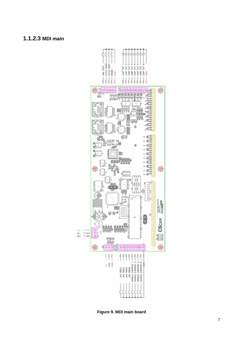
1.1.2.3 MDI main
Figure 9. MDI main board

8
1.2 NC Unit
Figure 10. NC Unit
1.2.1 LCD
Figure 11. LCD module
12.1 inch with XGA(1024X768)
3.3 V power supply
1 Channel LVDS interface
Single CCFL(Bottom side/Horizontal Direction)

9
1.2.2 Mainboard
Figure 12. Main control board
Socket P for Intel® Core™2 Duo / Celeron®
DDR2 1024MGbyte
IrDA, 1394, Digital I/O (4-in/4-out)
ICH8M, Winbond W83627EHG 1x IDE, 1x FDD, 1x KB, 1x Mouse, 1x RS-232, 1x RS232/422/485,
2x SATA II
SSD : CF socket (solder side) Display Interface : Supports CRT and 24-bit dual channel LVDS,
optional DVI
170mm x 170mm (6.7" x 6.7")
Max.Power Requirement : +5V: 4.15A +12V: 2.43A +3.3V: 1.06A
Operating Temperature : 0°C~60°C (32°F~140°F)
Storage Temperature : -20°C~80°C (-4°F~176°F)
Relative Humidity : 10%~90% (non-condensing)
Figure 13. Main board real connectors

10
1.2.3 CPU cooler
Bearing Type Two ball
Dimensions(DxWxH mm) 50x50x26
Fan Speed(RPM) 6000
Life Expectance(hrs) 40,000
1.2.4 Power supply
Figure 14. Power supply
Power supply – single 40mm TC Fan
82(W) X 150(L) X 43(H)mm
Voltage : 230V~, 50/60Hz, 2A

11
Output
Voltage +3.3V +5V +12V 1 -12V +5VsB
Electric current 10A 10A 9.5A 0.3A 2A
Combined power 500W
Total 120W
Number of connector
20 pin main connector 1 unit
+12V 4pin connector 1 unit
PATA(peripheral device) connector 2 unit
Serial ATA2 connector 1 unit
FDD connector 1 unit

12
1.2.5 Storage device
Figure 15. SSD 2.5 inch
22pin SATA2 Interface
Capacity : 4GB ~ 64GB
Performance : 100MB/s for Read, 80MB/s for Write(max)
Low power consumption
Low working temperature
1.2.6. Cable
Table 2. Cable standard
. Name standard
1 LVDS cable 12.1' 20P+20P 500mm
2 INVERTER CABLE 12.1' 3P+4P 500mm
3 USB
4. LAN CAT5e (STP) Standard LAN cable
5. PS/2

13
Figure 16. LVDS connector
Table 3. LAN cable technical details
Item Unit PVC/LSZH
Conductor resistance Ohms/100m 9.38
Conductor resistance unbalance
% 5
Electrostatic capacity nF/100m 5.6
Electrostatic capacity unbalance
pF/100m 330
Characteristic impedance
Ohms 100+-10%
Propagation delay ns/100m 538@100MHz
deviation of Propagation delay
ns 45
Propagation velocity % 67
Category temperature ℃/℉ -20~60/-40~140

14
range
Storage temperature ℃/℉ -20~80/-4~176
Radius 4xOuter Diameter
Type of package 300m/305m Reelex
Gross weight lb/kft(kg/km) 17(25)
Conductor diameter, material
24AWG, Solid Copper
Material and diameter of insulator outside
inch(mm) 0.035(0.90)Φ, HDPE
Material and diameter of cable outside
inch(mm) 0.189(4.8)Φ, PVC or
LSZH(Low Smoke Zero
Halogen)
Physical properties/plenum
UL 444/CMX-UL1581, IEC332-1/CM-UL1685, IEC332-3/CMR-
UL1666/LSZH-IEC61034, IEC60754
Electrical properties TIA/EIA-568-B.2/ISO11801 "Performance specifications for 4-Pair
100 Ohm Category 5E/D Cabling
Figure 17. Inverter cable

15
Figure 18 keyboard cable

16
1.3 AIB
Figure 19. AIB
• Product Name : Analog Axis Interface Board
• Input Voltage : 230V~, 50/60Hz, 2A
• Output Voltage : +5V, +12V, -12V
• DAC: +10V~-10V
• 엔코다 입력 : RS422(AM26LS32)
• I/O 입출력 +24VDC, NPN TYPE:
• 제품 사이즈 : (L)200mm ×(W)60mm ×(H)200mm

17
Figure 20. AIB Power
Figure 21. AIB-top layout

18
1.4 EtherCAT I/O

19
2 HX SYSTEM S/W
2.1 HX SYSTEM S/W Structure
2.1.1 Process Block Diagram
TURBO-HX Series System Architecture
Basic
MMI
MMI
Data
Alarm Process
ASF Function
or Thread
Map Manager Function
File Access Thread
System Interface Library
Operating System
Main CNC CPU H/W
PLC
Executor
Task
IPR
Task
IPO
Task
POS
Task
G
F
P
M
S X Y T
C R D
B
Shared Memory (CNC Map Data)
I/O Interface (CAN) SERCOS
Peripheral H/W Machine Logic & Sensor Servo/Spindle Drives
Hard Real Time Task Soft Real Time Task
PLC Inst.
Key in Process

20
2.2 Windows NT Installation (OS)
Please Follow the sequence below STRICTLY.
Sequence – Windows NT 4.0 -> Service Pack 4 -> MS
Explorer 4.01 -> RTX 4.2
(1) Insert Windows NT Workstation 4.0 CD and start the booting process. Before the
booting, go to Bios Setup and set it up to have CD ROM booted up first.
(2) While Windows NT is being installed, the basic installation files are read.
(3) After answering to the several basic questions about End User License Agreement,
select a drive and directory (folder) to be installed. In case a hard disk is new, “Create
Partition” message will pop up. There are two kinds; NTFS Type and FAT Type. In
case FAT Type is selected, C Drive will be created by automatically allocating 2GB
(Either FAT or NTFS can be selected. However, the drive set by NTFS can not be
accessed under Windows 95/98)
(4) If the drive and folder are set as shown above, the installation is automatically done.
Since then, just follow NT instructions.
During the installation, please set the Administrator Password to „hx (small letter)‟ for
Auto Logon. If you forgot to set the password during the installation of Window NT, please
set the password as follows after the installation:
(Password Setting Manually)
(1) Select [Start] -> [Program] -> [Administration Tools (Public)] -> [User Manager]

21
Program
Add Document Setup Find
Command Prompt
Window NT Explorer Administration Tools (Public) Serome Dataman Pro Startup
LG HomeLine-II
Disk Administrator
Backup User Manager System Performance Monitor Remote Access Manager Event Viewer
Windows NT Diagnosis
(2) Double click [Administrator]
User Manager
User Policy Option Help
User Name Full Name Description
Takes care of…
Backs up…
Cheon-Gi Park
Cheon-Gi Park
Cheon-Gi Park
Group Description
Takes care of computer / domain in overall
Backs up the file after passing through file security
Guest access right to computer / domain
Shares directory and print
Supports file copy from domain
General User

22
(3) Fill out Password and Confirm Password blanks with “hx (small letter)” and close User
Manager page. Then, log on again. Check if the new password is properly set.
User Registration Information
User Name Confirm
Full Name Cancel
Description: Built-in account for computer / domain management Help
Password
Confirm Password
Change password at the next logon
Can not change password
No time limit for use of password
Do not use account
Lock account
Group Profile Dial-in
If safely logged on to NT, the installation of Service Pack 4 starts.

23
2.3 Service Pack and Internet Explorer Installation
Once Service Pack 4 is executed, the service pack can easily be installed. Just follow the
instruction and press [OK] buttons. If the installation is finished, the installation of Internet
Explorer 4 starts. As shown above, just follow the simple instruction. If the installation up
to IE 4 is safely finished, the graphic card setting begins.
Select Control Panel -> Display or click the right button of the mouse and select
Registration Information. Then, Display Registration Information page will appear <The
figure on the left>:
Display Registration Information Wallpaper ScreenSaver Color Web Plus Setup Color Display Resolution Low High 1152X864 Pixels
Font Refresh Rate Small Font 75Hz All Display List Test Type Confirm Cancel
Type of Display Type of Adaptor Cancel Change Search Driver Information Manufactured by Version
Current File Adaptor Information Type of Chip Type of DAC Memory Size
Adaptor String: Unusable Bios Information: Unusable
Select Set and click Type of Display. Then, current graphic card information will appear.
Then, select [Change] button <The figure on the right>.

24
Change Display Please select Adaptor Manufacturer and Model. If there is an installation disk which was included with display adaptor, please press [Have Disk].
Manufacturer Display Have Disk
Confirm Cancel
Change Display page will pop up. Then, click Have Disk button and select a graphic card
drive folder. The graphic card drive will be installed.

25
2.4 RTX 4.2 Installation
Once Setup.exe is executed, the installation begins. A welcome message will appear
(Figure above). Then, click Next button.
A page in which the user information is entered will pop up (Figure on the left bottom).
Enter correct Customer ID (Customer ID: 32171)

26
Cheon-Gi Park Dept. of CNC Development, Technology Institute
Cheon-Gi Park Dept. of CNC Development, Technology Institute
Then, a page which confirms the input will pop up (figure on the right above). Check the
information and click Yes button.
Then, a page which asks the detail of installation will appear (see the figure below). Just
click Next button only and move to the next page.
It‟s a page which confirms License. Click Yes and move to the next page.
It‟s a page in which license key is entered (see the figure below). Please enter License
Key correctly.
(License Key: x_HYX=QMFb)

27
A page which sets RTX SDK will appear. Just click Next button only and move to the next
page.
The following warning message will pop up. Click Yes to continue the process.
A page which confirms the installation components will appear. If Next button is clicked,
the installation starts.

28
If the system is rebooted after the installation, RTX 4.2 installation will be finished.

29
2.5 Control Panel Setting
In Display Registration Information page, set ScreenSaver to N/A.
Boot the system and go to Control Panel.
Select SYSTEM in Control Panel. Then, Click Performance on top and [Change] button in
Virtual Memory. Then, the size of virtual memory can be adjusted. Set Initial Size and
Maximum Size under Paging File Size of Selected Drive to 200 and 300 respectively and
click Set and then Confirm button. Once Control Panel is closed, “Reboot System” message
will pop up. Then, reboot the system.

30
Control Panel File Edit View Go To Add Back Forward Top Cut
Copy Paste Address Control Panel Control Panel Display Mouse Multimedia
Modem Quick Search
Service Sound System Internet Telecommunication
System Registration Information General Performance Environment Start / End Hardware Profile User Profile Application Program Performance Please select Performance Improvement on
Foreground program Improvement: None Maximum Virtual Memory Total paging file size in all disk volumes 120MB
Change Confirm Cancel
Virtual Memory Drive [Volume Name] Paging File Size Confirm [Operating System] Cancel [Development] Help Paging File Size of Drive Selected Drive: [Operating System] Space Available: Initial Size Maximum Size Setup Total Paging File Size in All Drives Minimum: Recommended: Current: Registry Size Current: Maximum:
2.6 HX System S/W Installation
Insert DISK1 into the floppy drive and execute Setup.exe.
While Installshield activates, “Preparing..” message will pop up. Once the process is
completed, move to the next page. A welcome message dialog box will pop up. Once Next
button is clicked, it moves to the next page. (If CANCEL is clicked, in all dialog boxes, the
installation will be cancelled)
Welcome HX (Turbo Center) Installation
Initiating HX (Turbo Center) Installation Program…

31
“Select HX Installation Folder” dialog box will pop up. The default value is built-in to the
system. In order to change it into another name, click Browse button and select the folder
you want. Once selection is completed, click Next button. [Notice: When a folder to be
installed is selected, there should be no blank spaces. Ex: HX2.0.0 (O) vs. HX 2.0.0 (X)]
Select HX (Turbo Center) Installation
Folder
Please select a folder in which HX (Turbo Center) will be installed.
Operating System
“Select Program Folder” dialog box will pop up. The folder under „START – PROGRAM‟ is
named. The default value is built-in to the system. In order to change it into another name,
just enter the name you want. Once selection is completed, click Next button.
Select Program Folder
Please select a folder which will be registered in Startup Program.
Administration Tools (Public)
Serome Dataman Pro
Startup Program

32
Internet Friend
E-Tran 98
Installation begins.
Once the installation is completed, the registered folder will appear. Then, [Setup] page
will pop up in the end.
File Edit View Go To Add Help
Back Forward Top Cut Copy Paste
Address

33
Select an icon for detail information Remove HX
In Setup page, “Installation Completed” dialog box is found. [Yes] and [No] buttons are
also seen under the message „System has changed. Please restart the computer.‟ Select
[Yes] and click Finish button.
Installation Completed
The installation of HX (Turbo Center) has been completed.
Please reboot the system.
Please click [Finish] button.
Window is restarted (Please remove the disk from the floppy drive)
Installation is completed.
▶ Additional Setting by Type
The machine can have a different resource (datafile, bitmap, etc.) by manufacturer.
Then, the related files which are provided in ServicePack should be additionally installed.
Ex) If syslogo.exe in Washing under Gas of ServicePack is executed and the zip file is
opened in a related folder, the system will be booted with the logo image (For more
information, refer to „PleaseRead.txt‟)

34
2.7 Additional Setting
After TURBO-HX CNC S/W is installed, the equipment can not be operated immediately.
In order to operate the equipment, the files required for the operation should be added as
follows:
(1) Click [View] menu and select [Folder Option]
(2) Select [View] in Folder Option page and see [Advanced Setup]
(3) Check [Hide Registered File Format Extension]
(4) Check [Mark All Files] under [Hidden File]. Then, click [Confirm] to close the
Folder Option page (If it‟s already checked, just leave it as it is).
View Go To Add Tool Bar Status Bar Explorer Bar Webpage Type Large Icon Small Icon Lightly Detail Current Folder User Definition Icon Array Refresh Option
General View File Format View Folder All folders can be created in a same format. Like Current Folder Reset All Folders Advanced Setup Display file attributes in details Display the network drive connection button in tool bar Hide the registered file format extension Files hidden Display all files Do not display hidden files and system files Do not display hidden files Use large character name Restoration Confirm Cancel Apply
Then, continue the process in Explorer page as follows:

35
(1) Select PLC folder under HX folder in HDD. Put three files in this folder: (TLADDER.ini
TURBOHX1.fun TURBOHX1.ini). Put two files with „#la‟ and „#sy‟ as extension
(regardless of file name). Besides, put PLCAlmDT.txt and PLCOpDt.txt. (The five files
above are saved in the sealed HX CNC Program Installation CD)
(2) Go to System folder under HX folder. Install a separate file with „h2p‟ as extension
(regardless of file name) (This file is also saved in the sealed HX CNC Program
Installation CD)
(3) Then, execute SramClear_Sercos.exe in HX folder for initialization.
(4) If completed, execute CNCHX.exe in HX folder.
Once a file is being executed, “Loading..” message will pop up.
If a finished message appears, TURBO-HX CNC page will show up.
(If an error occurs during the loading process, write down the error message and contact
the Dept. of Customer Support)
If things have been properly executed until now, the equipment can be operated now.

36
2.8 HX Created Folder
HX Backup
Bmp
Data
Help/Screen
NC/Macro
PLC
System
TURBO-HX CNC is structured as above. Each folder can be stated as follows:
HX Main Folder
TURBO-HX CNC execution file-related DLL files exist.
There are 4 kinds of execution files as follows:
CNCHX.exe: A program which activates HX system
Double click the program or register it in Startup to make it auto-
started at booting
CNCHX32.exe: A program which activates HX system in which the main memory is
32Mbyte
Under the system in which the main memory is 36Mbyte, make sure
that this file is registered in Startup.
SramClear_Sercos.exe: A program which initializes Battery Backup S-RAM
RTXALL.BAT: It removes the residual processes while HX system is not properly
closed. If HX system is not properly shut down, this program must be executed. If
this file is not available, you should take the trouble to turn off and on the system.
HX Internal Folder (Sub Folder)
Backup Folder – rtss file which is necessary for the execution of CNC program
exists (*.rtss)
Bmp Folder – Several Bitmap files which are used in CNC program exist (*.bmp)
Data Folder – CNC program-related data files exist (*.txt). In the inside of data
folder, besides, a sub folder called Parameter exists in which parameter status and
diagnosis format-related data exist.
Help Folder – HELP file (*.html) and related image files which are used in CNC
program exist.

37
Help/Screen Folder – HELP file can be created against the page added by a user.
NC Folder – As a folder in which the process program is stored, it‟s automatically
connected with “NC DIR” while CNC program is on.
NC/Macro Folder – A system macro program (9000.NC~9029.NC) file exists. If the
macro program is called in a program, this program will be executed.
PLC Folder – A folder in which PLC related files that are used in CNC exist
If no file exists in this folder, CNC program does not operate normally.
The two files with „#la‟ and „#sy‟ as extension are loaded at an early
stage of execution. In case several files with the same extension as
shown above exist, a file which is earlier alphabetically will be read
first. Besides, Korean file name is prior to the file name in English.
(Tladder.ini Turbohx1.fun Turbohx1.ini and two files with „#la‟ and
„#sy‟ as extension) PLC alarm and warning message file can be added
(PLCAlmDT.txt 와 PLCOpDt.txt ).
System Folder – A folder in which the files which are related with the system that
operates CNC program exist
The files in this folder are automatically updated when the
program is closed (If a file does not exist, a new file is created).
However, if the file with „h2p‟ as extension does not exist when HX
is first executed, the program can not be operated normally. A file
which separately handles the files with „h2p‟ as extension should
be installed (parameter file)
◆. PDAx_OO.hxs exists in Sercos folder in System folder. This files stores Sercos
related set values by axis.
◆. At the execution of CNC program, „*.h2p‟ files (parameter files) in System folder
is loaded in the beginning.
In case several files with the same extension as shown above exist, a file which is
earlier alphabetically will be read first. Besides, Korean file name is prior to the file
name in English.
If no file exists, a file is automatically created under the name of „default.h2p‟ when
the program is closed.

38
2.9 Additional Setting for Auto Logon
In order to make Auto Logon activated, the system should be secured with password
protection. If it‟s not secured with password (Just press [Enter] and Log on), Auto Logon
is executed just once at an early stage.
If there is no password, please refer to Password Setting in 2.2 Window NT Installation.
In order to network with other computers with LanCard, DefaultDomainName must be set
additionally. Otherwise, DefaultUserName and DefaultPassword only should be set.
(Both items should also be set if LanCard is used)
First select START – RUN, and enter “regedit.”
Program Add Document Setup Find Help Run Park Cheon-Gi Log Off Shut Down Startup
Run Please enter Program, Folder, Document, or Internet Resource to open. Open: Execute in different memory area Confirm Cancel Browse
Registry editing window is opened. Then, select
HKEY_LOCAL_MACHINE\SOFTWARE\Microsoft\Windows NT\CurrentVersion\Winlogon.
If LanCard is first installed after Service
Pack 4 is installed, a network error
occurs. In this case, make a copy of
srv.sys in „WINNT\system32 \drivers‟ and
insert it to the same folder with HX
system.

39
My Computer
Registry Editor
Registry Edit View Help Name Data
(Basic Value) (N/A)
Park Cheon-Gi
■ If any item mentioned below does not exist, it should be added.
■ In order to add an item, select String Value of New under Edit menu.
■ Then, enter domain name in DefaultDomainName. (It‟s like TURBO_CHUNGWON in
case of Cheongwon Office of Turbotek. If it‟s used in Local only, just leave it
empty.)
■ Enter user name in DefaultUserName. (It‟s administrator in case LAN is not used)
■ Enter password in DefaultPassword. (It‟s hx in case LAN is not used)
■ In order to use AutoLogon, enter 1 to AutoAdminLogon. In order not to use it,
enter 0.
■ Then, close the registry editor and log on again.
40
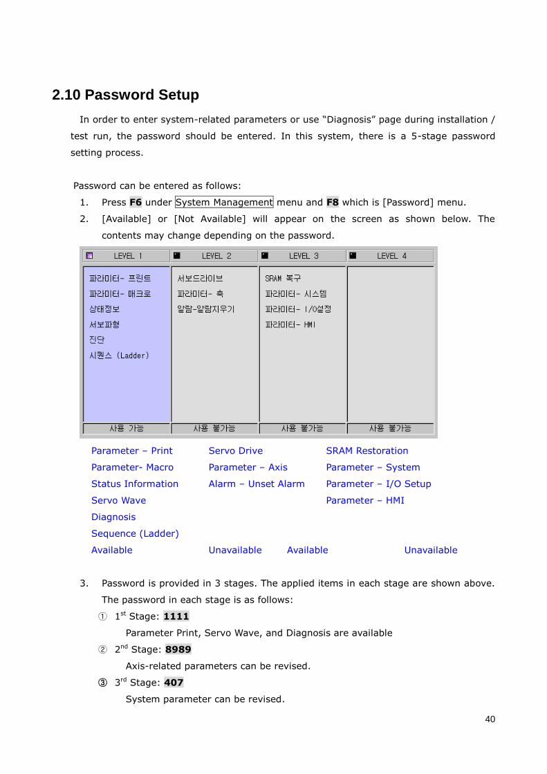
2.10 Password Setup
In order to enter system-related parameters or use “Diagnosis” page during installation /
test run, the password should be entered. In this system, there is a 5-stage password
setting process.
Password can be entered as follows:
1. Press F6 under System Management menu and F8 which is [Password] menu.
2. [Available] or [Not Available] will appear on the screen as shown below. The
contents may change depending on the password.
Parameter – Print Servo Drive SRAM Restoration
Parameter- Macro Parameter – Axis Parameter – System
Status Information Alarm – Unset Alarm Parameter – I/O Setup
Servo Wave Parameter – HMI
Diagnosis
Sequence (Ladder)
Available Unavailable Available Unavailable
3. Password is provided in 3 stages. The applied items in each stage are shown above.
The password in each stage is as follows:
① 1st Stage: 1111
Parameter Print, Servo Wave, and Diagnosis are available
② 2nd Stage: 8989
Axis-related parameters can be revised.
③ 3rd Stage: 407
System parameter can be revised.

41
2.11 Battery Backup Memory
Use of Battery Backup Memory
Under HX system, the system operation-related data are saved using the battery backup
SRAM in NC Interface Card. The information such as internal timer (T map), internal
counter (C map), internal relay (R map), internal data (D map), global macro variables
(#200-#699), machine coordinate in each axis, and the program selected under AUTO
mode is stored in SRAM. This kind of information is restored in „*.h2b‟ file under system
folder whenever HX system is shut down.
If SRAM will be used or not can be set when HX system is installed. In case SRAM is not
used (PI[1415] parameter = 1), the data are stored in „*.h2b‟ file under system folder.
In case SRAM is not used, the data such as T, C, R, D, and global macro variables
(#200-#699) will be saved in „*.h2b‟ file under system folder by an interval set by PI[1416]
parameter.
Program User Process 1 Process 2 System Macro Axis I/O Setup Special Function HMI
Hardware Setup
Select Key Panel
Key Use COM Port No.
If SRAM is used (0: Used, 1: Not Used)
If SRAM is not used, save it in file system by an interval
Restoration of Battery Backup Memory
In case the data stored are damaged under the mode in which the battery backup
memory is used, the previous data should be restored due to the replacement of NC
Interface Card, or the same data are used to mass-production machine, „SRAM Restoration‟
function which is provided by HX system can be used.
The operation is as follows:
(1) Enter password (1004) to make „SRAM Restoration‟ menu appear on the screen.
(2) Check if PI[1415] „IF SRAM IS USED‟ is set to „1‟ USED.
(3) Have the normal „*.h2b‟ ready

42
(4) Make EMG-STOP state using EMP-STOP switch
(5) Make a copy of the „*h2b‟ file to /system folder under HX system
(6) Press „SRAM Restoration‟ menu.
Main PG Tool
Ongoing PG
Parameter – Print Servo Drive SRAM Restoration
Parameter- Macro Parameter – Axis Parameter – System
Status Information Alarm – Unset Alarm Parameter – I/O Setup
Servo Wave Parameter – HMI
Diagnosis
Sequence (Ladder)
Available Unavailable Available Unavailable
Alarm Hide Screen SRAM Restoration Status Information
Servo Wave Diagnosis Password
SRAM Restoration Menu

43
3 PLC
3.1 HX PLC EDITOR Installation
3.1.1 HX PLC EDITOR Installation
(1) Download the compressed HX PLC Editor file and decompress it to an arbitrary folder.
(2) In Data subfolder, Turbohx1.ini, Turbohx1.fun, and Tladder.ini files are created. Also, the FX
version configuration files, such as Fxladder.ini, FxPlus.fun, and FxPlus.ini, are created as well. FX
version configuration files are used for the editing of FX system ladder file that the file extension is
*.fxl.

44
3.2 Using HX PLC EDITOR
3.2.1 Running HX PLC EDITOR (1) Run HxEditor.exe.
(2) The following screen is displayed.
3.2.2 PROJECT Management Screen (1) If you use HX PLC editor for the first time, no file is shown in the Project window. Basically, the file
information registered to Project is stored to Default.pws file in the folder where HXEditor.exe is
located.
(2) PLC Library Files
: Ladder library file that has the extension of .#lb can be registered. Library file is the ladder file
written in module unit. For example, End1.#lb is a module that only contains „END1‟ command. In
the property information, the file storage path information is contained.
(3) PLC Ladder Files
: Registers the ladder file that has the extension of .#la. Ladder file using the library can create a
new ladder by orderly selecting the desired library files using the Merge function of utility (Alt+u).
After selecting a ladder from Project window, you can perform additional tasks.

45
3.2.3 Open Ladder File 1) Open a New File
(1) Select New File menu item from File menu to select a file type.(Ladder file, Library file, and FX
ladder file)
(2) Ladder1 Ladder window is opened and the toolbar is activated.
(3) By clicking on the toolbar icon or using F1 ~ F8 keys, you can edit the ladder diagram.
Project Window
Ladder/Library Editing

46
2) Open existing ladder file or library file
(1) Double click on a desired ladder file from PLC Ladder Files menu in the left Project window. Or
select Open from File menu. File Selection dialog is displayed.
(2) Select a file with .#la extension. (Symbol file (*.#sy) is automatically created and saved.)
[CAUTION]
(1) Be sure to use different name for Library file (#lb) and ladder (#la) file. If they are the same,
the contents of the symbol file will be altered when creating a ladder file using Merge function.
(2) Symbol file (*.#sy) for the Library file (#lb) and Ladder (#la) file is automatically created and
saved.

47
3.2.4 Open Symbol File (1) By selecting Symbol File Edit menu item from Utility menu, you can edit a desired symbol file. (Use
of new editor is also possible.)
(2) By selecting Symbol File Edit from the pop-up menu shown by right mouse clicking on Project
Workspace, you can edit a desired symbol file.
3.2.5 Create and Open Project File (1) Create and Open / Save Project functions are provided by right mouse clicking on the left Project
window. Ladder files with various names per equipment type can be created and managed in
Projects.
(2) To create a new Project, enter a new name in the Project Selection window.

48
3.2.6 Ladder (#la) Creation using Library(#lb) File
: Select Merge function from Utility menu item of File menu.
1) Using a Dialog Window
(1) Select Merge from Utility menu item of File menu.
(2) The following dialog is displayed.
2) Usage
1) Select a desired module from the Library List window on the right. Ladder file is constructed
according to the selection order.
(2) “<<Select” Button: Modules selected from the list window are orderly registered to the left library
composition window.
(3) “Up” Button: Bring the selected module to the top of the library composition window.
(4) “Down” Button: Bring the selected module to the bottom of the library composition window.
(5) “Delete” Button: Deletes the selected module from the library composition window.
(6) “Select” button of the Ladder Filename selection section: PLC Ladder File selection window is
displayed. Enter a desired name here or select an existing name by pressing the Select menu.
(7) “Merge” Button: Ladder file is created and automatically registered to the project list.
Library list window
Library contents window
Ladder Filename Selection

49
3.2.7 Ladder Editing 1) Use of Toolbar and FunctionKey
(1) Click on a position where you wish to enter an element.
(2) Rectangular cursor moves toward the selected position.
(3) Click on an element to enter from the toolbar.
(4) For a horizontal or vertical line, it is directly drawn on the screen. And for the rest of the elements,
dialog box is displayed for you to enter the required information. When you pres Enter key or
click on OK button, defined element is entered to the selected position.
(5) When selecting an element from the toolbar, place the cursor on an element and press the left
mouse button.
1.1) RD Symbol (F1 Key)
-> Input symbol.
1.2) RDN Symbol (F2 Key)
-> Input highlighting symbol.
1.3) WR Symbol (F3 Key)
-> Output symbol.
1.4) WRN Symbol (F4 Key)
-> Output highlighting symbol.
1.5) Function Symbol (F5 Key)
> Function command input symbol. Only one function command is allowed for a LUNG.
1.6) Horizontal Line Symbol (F6 Key)
-> Horizontal line symbol.
1.7) Delete Symbol (F7 Key)
-> Place the cursor box to an basic element or function command and press F7 key or click on the corresponding symbol from the Toolbar to delete it. (However, vertical line can only be deleted when pressing Shift + F8 key.)
1.8) Left Vertical Line Symbol (F8 Key)
-> Draws a vertical line upward on the left of the current cursor position. -> To delete a left vertical line, press Shift+F8.
1.9) New Line Insertion (F9 Key)
-> Inserts a new blank line right below the current cursor position.

50
2) Basic Command and Function Command Input Method
2.1) Basic Command Input Method (Common to RD, RDN, WR, and WRN)
Since HX PLC is a 32-bit PLC, it can express 32bits per address.
The bit value expression next to “.” follows the hexadecimal notation.
32 bit values are counted from 0 to 31.
Example 1) 7th bit that has the address of X20 : X20.07(O), X20.7(X)
Example 2) 9th bit that has the address of X20 : X20.09(O), X20. 9(X)
Example 3) 11th bit that has the address of X20 : X20.0B(O), X20. B(X)
Example 4) 15th bit that has the address of X20 : X20.0F(O), X20. F(X)
Example 5) 31st bit that has the address of X20 : X20.1F(O), X20. F(X)
Proc. #1. When you select one from RD, RDN, WR, or WRN command using mouse or keyboard, the
following Basic Command Properties dialog is shown.
Proc. #2. Enter the address. (Mandatory)
If you are only entering the address, enter the address and press Enter key, and if you are adding a
name or comments, move the cursor to the corresponding position using Tab key or mouse.
Proc. #3. Enter the name (symbol). (Only when required. Hangul can be used.)
Since about 6 ~ 8 letters can be expressed on the screen although the number of symbols for a name
is limited to 30 letters, it is recommended to use a name that does not exceed 8 letters.
Proc. #4. Enter the Relay comments. (Only when required. Hangul can be used.)
Make sure the comments for the address (Relay) does not exceed 30 letters.
Proc. #5. Enter the Coil comments.
(Hangul can be used. Enter it only when it is used as the output coil. X, F are not required).
Proc. #6. Click on OK button or press Enter key.

51
2.2) Function Command Input Method
(1) When you press F5 key, the following Function Command Properties dialog is shown.
(2) Select a function command.
A. Using keyboard: Enter the first letter of the function command to select and click on the down
arrow „‟. The function commands starting with the entered letter are searched. Select a
desired function command and then, press Enter key.
B. Using mouse: When you select “” from the command edit box, the whole alphabetized
function command list is shown. Select a desired function command and then, press Enter
key or click on OK button.
(3) Enter the operand of the function command shown in the screen.
The following diagram shows the procedure for entering the operand after selecting SUB36
ADDB command. When you double click on an operand or click on an operand and press Enter
key, Operand Input dialog is displayed.
A. Input of the first operand.

52
B. Input of the second operand.

53
C. Input of the third operand.
D. Ladder screen upon completion of operand input.

54
3.2.8 Edit Configuration and Functions
1) Grid Setting
Function) Selects the grid show option and sets the number of grid columns.
Default value is 9 and up to 20 columns can be set. (Although it can be extended, but cannot
be shrunken)
[CAUTION] The cursor box does not move below the vertical count set during the editing. To
increase the vertical count, use Line Insert toolbar symbol.
2) Ladder Display Setting
When you select symbol from the toolbar, the following Screen Display Mode setting dialog is
displayed.
You can select the combination of comments to be displayed on the screen.

55
3) Editing Function
3.1) Insert Line Function (F9)
Increases the gap between the ladder rung and rung. It is frequently used during editing
work.
3.2) Delete Line Function
Reduces the gap between the ladder rung and rung.
3.3) Current Rung Deletion ( Rung Delete : Shift + Del )
Deletes the Rung where the current cursor is located.
3.4) Cut function (CUT : Ctrl + X )
Cut function in rung units. It is only applied to the completed rungs.
Select the starting and ending rung number to cut.
3.5) Copy function (COPY : Ctrl + C )
Copy function in rung units. It is only applied to the completed rungs.
Select the starting and ending rung number to copy.
3.6) Paste Function (PASTE : Ctrl + V )
Cut function in rung units. It is only applied to the completed rungs.
3.7) Row Shift (Ctrl + G)
When you select the Row Shift function, the following Shift dialog is displayed. Enter the Rung or Step
number to search and then, press Enter key to move the cursor to the corresponding position.

56
3.8) Search Function (Ctrl + F)
When you select Search function, the following Search dialog is displayed. If you press
Enter key after entering a desired address or function command, the cursor moves to the corresponding
position. If you wish to continue to search, press F11 key.
3.9) Replace Function (Ctrl + E)
If you select the Replace function, the following Replace dialog is displayed. Enter both the old
address and new address and then, press Enter key to perform replacement operation.
3.10) Shift Substitution Function (Ctrl + H)
Shift Substitution function changes the address group from the selected starting address to the ending
address to another address group format in a batch. When you select this function, the following Shift
Substitution dialog is displayed. Enter the starting address and ending address to be substituted as
well as the new starting address.

57
3.11) Printing Function
(1) When you select Print from File menu, the following Print Options dialog is displayed for you to
select the printing contents.
(2) Edge List option prints the symbols used in the ladder diagram in a report format.
(3) Ladder option prints the diagram in the ladder screen.
(4) Show Print Dialog option determines to show Print dialog during printing.
(5) When you do not check Show Print Dialog option, all pages are printed. (Partial printing of the
selected page(s) is disabled.)
[CAUTION] This option is used to disable Print dialog functions in case of Print dialog failure in
Windows 95/98.
3.12) Print Preview Function
Provides the screen preview prior to the actual printing.
[CAUTION] It may take some time to print a large sized file.

58
3.3 HX PLC Specification & Commands
3.3.1 Ladder Program Execution Sequence 1) Ladder Program Overview
PROGRAM OF LEVEL 1
END 1
PROGRAM OF LEVEL 2
END 2
SUBROUTINE PROGRAM
[ Fig.1 ] Ladder Program Structure
PLC Ladder Program is basically composed of LEVEL-1 and LEVEL-2. After LEVEL-2,
Subroutine Program can be used.
In the program composition, END1 and END2 command must exist.
LEVEL-1 is a high-speed sequence and should be used to process the high-speed sequence
such as short pulse signal. Routine function that should be performed with a certain interval
and functions that should be handled immediately should be programmed here. In these
signals, the input processing signal that has the significant effect on the system such as the
Emergency Stop, Feed Hold, and/or Tool Change, is included. LEVEL-1 coding should be
written to allow fast processing within a short period of time. Although it is possible, it is
recommended not to use Subroutine Call.
LEVEL-2 is a routine for processing other sequences than LEVEL 1. LEVEL-2 processing is
made in groups of 6000 steps.
The overall processing time of the program can be checked from the system.
600 steps
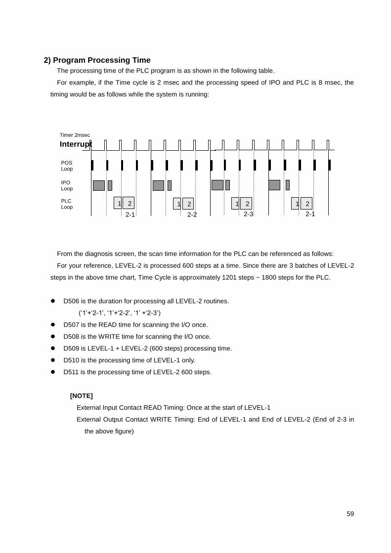
59
2) Program Processing Time
The processing time of the PLC program is as shown in the following table.
For example, if the Time cycle is 2 msec and the processing speed of IPO and PLC is 8 msec, the
timing would be as follows while the system is running:
From the diagnosis screen, the scan time information for the PLC can be referenced as follows:
For your reference, LEVEL-2 is processed 600 steps at a time. Since there are 3 batches of LEVEL-2
steps in the above time chart, Time Cycle is approximately 1201 steps ~ 1800 steps for the PLC.
D506 is the duration for processing all LEVEL-2 routines.
(„1‟+„2-1‟, „1‟+„2-2‟, „1‟ +„2-3‟)
D507 is the READ time for scanning the I/O once.
D508 is the WRITE time for scanning the I/O once.
D509 is LEVEL-1 + LEVEL-2 (600 steps) processing time.
D510 is the processing time of LEVEL-1 only.
D511 is the processing time of LEVEL-2 600 steps.
[NOTE]
External Input Contact READ Timing: Once at the start of LEVEL-1
External Output Contact WRITE Timing: End of LEVEL-1 and End of LEVEL-2 (End of 2-3 in
the above figure)
Timer 2msec
Interrupt
PLC Loop
POS Loop
IPO Loop
1 2 1 2 1 2 1 2
2-1 2-2 2-3 2-1

60
3.3.2 ADDRESS 1) Address Structure
Address is the number for representing the location of signals such as the machine-side I/O signal,
CNC I/O signal, internal Relay, Timer, Counter and Data Table.
[ Fig.2 ] PLC Related Address
PLC External Data
X : External Input
Y : External Output
PLC Internal Data
T : Timer
C : Counter
R : Internal Relay
D : Internal Data (Integer type)
Interface Data between PLC and CNC (PLC-based)
G : Internal signal from PLC to CNC (PLC CNC)
F : Internal signal from CNC to PLC (CNC PLC)
Securely maintained
(1) TIMER
(2) COUNTER
(3) DATA TABLE
INTERNAL RELAY
P L C Machine Related
Signal CNC Related
Signal
G X
F
R
Y
T,
C,
D

61
2) External I/O Signal (Input: X, Output: Y)
Basically, X enables Read and Y enables Read/Write operation.
When accessing X or Y address, it can be accessed in 32 bit or 1 bit units. For a 32 bit unit, the
address is incremented by 1.
For HX system, internal X address may be used when using the Soft OP.
Variable Name Unit Capacity Size (Byte)
X 256(8192 Points) 1 Kbyte
Y 256(8192 Points) 1 Kbyte
3) Internal Data (Timer:T, Counter:C, Data:D)
T, C, and D are all 32 bit Read/Write operation and basic Address increment is done in 32 bit units.
Variable Name Unit Capacity Size (Byte)
T 512 4 Kbyte
C 512 4 Kbyte
D 4096 16 Kbyte
4) Internal Relay (R)
For accessing the R Address, it can be accessed in 32 bit units or 1 Bit unit. For a 32 bit unit, the
address is incremented by 1.
R Address is divided into the front volatile area (R0.00~1023.1F) and rear non-volatile area
(R1024.00~R2047.1F) around the half of the size. Volatile area is always reset to 0 during booting.
Variable Name Unit Capacity Size (Byte)
R 2048 (65536 Points) 8 Kbyte
5) Internal System I/O Signal (Input:F, Output:G)
F and G Address is the interface signal between PLC and CNC and those addresses are predefined.
When viewed based on the PLC, F address becomes a READ signal from CNC and G address
becomes a WRITE signal to CNC.
For accessing the G and F Address, it can be accessed in 32 bit units or 1 Bit unit. For a 32 bit unit,
the address is incremented by 1.
Variable Name Unit Capacity Size (Byte) Location
G Common 1000 (32000 Points) 4000 byte NOTE: System Memory Size = 40 Kbyte (4 X 2 X 4+ 8) F Common 1000 (32000 Points) 4000 byte

62
3.3.3 HX PLC Commands 1) Address Expression Format
Address expression is composed of the address name, address number and bit number as shown in
the following format. In other words, address is used for all signals. But, bit number may not be used (for
T, C, and D)
(Ex) F 35.02 Address Name
Address Number
Bit Number
2) Command Types
There are the basic and function commands in HX PLC commands.
2.1) Basic Commands
There are 12 types of basic commands that performs the bit operation such as AND or OR and they
are frequently used for designing the sequence program.
2.2) Function Commands
27 types of function commands are used to program the maneuvering machine operation that are
difficult to program only with the basic commands.
3) Storage of the Logical Operation Result (Stack Register)
Result of the logical operation is temporarily stored to the stack register during each operation. Stack
Register is composed of 1Bit + 31Bit (Total of 32 bits) as shown below.
When you use the storage command (RDS) that temporarily memorizes the result during the previous
operation, the bit values are shifted to the left as shown above. Also, when you use the recalling function
(ANDS) of the retracted signals, they are shifted to the right. The last retracted signal is recalled the first.
Address Name Address Number. Bit Number
SR31 SR30 SR5 SR4 SR3 SR2 SR1 SR0
Result of the current
operation is stored. Stack Register (Temporarily stores
the result of the previous operation)

63
No. HX-PLC
Command
PLC Conv. Code (Hex)
Description
1 RD 01h Sets ST0 by reading the logic status of the specified signal.
2 RDN 02h Sets ST0 by reversely reading the logic status of the specified
signal.
3 WR 1Eh Outputs the logical operation result (ST0 status) to the specified address.
4 WRN 1Fh Outputs the logical operation result (ST0 status) reversely to
the specified address.
5 AND 03h Performs the logical multiplication.
6 ANDN 04h Performs the logical multiplication by reversing the logical status of the specified signal.
7 OR 05h Performs the logical sum.
8 ORN 06h Performs the logical sum by reversing the logical status of the specified signal.
9 RDS 07h Shifts the contents of the stack register to the left by 1 bit and
sets the status of the specified address signal to ST0.
10 RDNS 08h Shifts the contents of the stack register to the left by 1 bit and sets the reversed status of the specified address signal to ST0.
11 ANDS 14h Sets the logical multiplication of ST0 and ST1 to ST1 and shifts the contents of the stack register to the right by 1 bit.
12 ORS 15h Sets the logical sum of ST0 and ST1 to ST1 and shifts the contents of the stack register to the right by 1 bit.

64
4) Basic Command Format
Command: Address Name Address Number . Bit Number
(ANDS and ORS command is used alone.)
(NOTE1) In [Fig.] and [Table],
①, ②, ③… represents the a contact while , , ... represents the b contact.
+ refers to the logical sum, and
* refers to the logical multiplication.
(NOTE2) In [Fig.] and [Table],
SR0 refers to the 0 bit of the stack register,
SR1 refers to the 1st bit,
SR2 refers to the 2nd
bit,
…
SR31 refers to the 31st bit, respectively.

65
5) Basic Commands
5.1) RD ( READ )
Reads the logic status (1 or 0) of the specified address signal and writes to SR0.
It is used when starting the coding from A contact.
Example
[ Fig. 4.1 ] RD Ladder Diagram
[ Table 4.1 ] RD Operation Procedure
No. Command
Address Remark
SR3 SR2 SR1 SR0
1 RD X00.01
①
2 WR Y00.01 W1
Output
①
5.2) RDN ( READ NOT )
Reversely reads the logic status of the specified address signal and writes to SR0.
It is used when starting the coding from B contact.
Example
[ Fig. 4.2 ] RDN Ladder Diagram
[ Table 4.2 ] RDN Operation Procedure
No Command
Address Remark
SR3 SR2 SR1 SR0
1 RDN X1.02
2 WR Y3.01 W1
Output
X01.0 Y00.0
W
1
①
W
1

66
5.3) WR ( WRITE )
Outputs the logical operation result, the status of SR0 (1 or 0) to the specified address.
One logical operation result can be used for more than 2 addresses.
Example
[ 그림 4.3 ] WR Ladder Diagram
[ Table 4.3 ] WR Operation Procedure
No. Comm
and Address Remark
SR3 SR2 SR1 SR0
1 RD X1.00
①
2 ANDN Y3.02
①*
3 WR Y2.00 W1
Output
①*
4 WR Y3.01 W2
Output
①*
5.4) WRN ( WRITE NOT )
Reverse the status of SR0 (1 or 0) and outputs it to the specified address.
Example
[ Fig. 4.4 ] WRN Ladder Diagram
[ Table 4.4 ] WRN Operation Procedure
No. Command
Address Remark
SR3 SR2 SR1 SR0
1 RD X1.01
①
2 ANDN X1.06
①*
3 WRN G3.01 W1
Output
①*
①
① W
1

67
5.5) AND ( AND )
Performs the logical multiplication of the logic status of the specified address signal and SR0 and
writes the result to SR0.
Example
[ Fig. 4.5 ] AND Ladder Diagram
[ Table 4.5 ] AND Operation Procedure
No. Comm
and Address Remark
SR3 SR2 SR1 SR0
1 RD X2.02
①
2 AND X3.02
①*②
3 OR Y1.03
①*②+③
4 WR Y2.03 W1
Output
①*②+③
5.6) ANDN ( AND NOT )
Performs the logical multiplication of the reversed logic status of the specified address signal and SR0
and writes the result to SR0.
Example
[ Fig. 4.6 ] ANDN Ladder Diagram
[ Table 4.6 ] ANDN Operation Procedure
No. Comm
and Address Remark
SR3 SR2 SR1 SR0
1 RDN X3.04
2 AND X2.06
*②
3 ANDN Y3.01
*②*
4 WR G2.01 W1
Output
*②*
① ②
③
②

68
5.7) OR ( OR )
Performs the logical sum of the logic status of the specified address signal and SR0 and writes the
result to SR0.
Example
[ Fig. 4.7 ] OR Ladder Diagram
[ Table 4.7 ] OR Operation Procedure
No. Command
Address Remark
SR3 SR2 SR1 SR0
1 RDN X0.06
2 OR Y2.07
+②
3 WR G1.01 W1
Output
+②
5.8) ORN ( OR NOT )
Performs the logical sum of the reversed logic status of the specified address signal and SR0 and
writes the result to SR0.
Example
[ Fig. 4.8 ] ORN Ladder Diagram
[ Table 4.8 ] ORN Operation Procedure
No. Command
Address Remark
SR3 SR2 SR1 SR0
1 RDN X0.03
2 ORN G2.01
+
3 WR G12.01 W1
Output
+
②

69
5.9) RDS ( READ STACK )
Shifts the contents of the stack register to the left by 1 bit and writes the logic status of the specified
address signal to SR0.
It is used when the specified signal is A contact.
Example
[ Fig. 4.9 ] RDS Ladder Diagram
[ Table 4.9 ] RDS Operation Procedure
No. Command
Address Remark
SR1 SR0
1 RD X2.01
①
2 AND Y1.07
①*②
3 RDS Y3.01
①*② ③
4 AND X1.01
①*② ③*④
5 ORS
①*②+③*④
6 WR G2.01 W1
Output
①*②+③*④
①
③ ④
②

70
5.10) RDNS ( READ NOT STACK )
Shifts the contents of the stack register to the right by 1 bit, and writes the reversed logic status of the
specified address signal to SR0.
It is used when the specified signal is B contact.
Example
[ Fig. 4.10 ] RDS Ladder Diagram
[ Table 4.10 ] RDS Operation Procedure
No. Command
Address Remark
SR1 SR0
1 RD X1.01
①
2 AND
N Y3.04
①*
3 RDN
S X1.07
①*
4 AND Y3.05
①* *④
5 ORS
①*+*④
6 RDN
S R2.01
①*+*④
s7 AND
N R3.04
①*+*④ *
8 ORS
①*+*④+*
9 WR Y1.03 W1
Output
①*+*④+*
①
④

71
5.11) ANDS ( AND STACK )
Writes the result of the logical multiplication of SR0 and SR1 in the stack register to SR1 and shifts the
contents of the stack register to the right by 1 bit.
Example
[ Fig. 4.11 ] RDNS Ladder Diagram
[ Table 4.11 ] RDNS Operation Procedure
No. Command
Address
SR3 SR2 SR0
1 RD X1.06
①
2 ANDN X2.02
①*
3 RDNS X2.06
①*
4 ANDN Y2.01
①* *
5 ORS
①*+*
6 RDS X2.04
①*+* ⑤
7 ANDN Y3.06
①*+* ⑤*
8 RDS R1.05
①*+* ⑤* ⑦
9 ANDN R6.04
①*+* ⑤* ⑦*
10 ORS
①*+* ⑤*+⑦*
11 ANDS
(①*+*)
*(⑤*+⑦*) 12 WR Y2.03
5.12) ORS ( OR STACK )
Writes the result of the logical sum of SR0 and SR1 in the stack register to SR1 and shifts the
contents of the stack register to the right by 1 bit.
Example
Refer to [ Fig. 4.11 ] and [ Table 4.11 ].
①
⑤
⑦

72
6) PLC Function Command
(Format) Function Command Code OP1 OP2 OP3 , …..
Note) The number of operands may vary by the function command.
Command
Code
Command
No. of
Var. Var. Type
No. of
Input
No. of Output
Description Remark
1 END1 0 0 0 LEVEL-1 program ended
2 END2 0 0 0 LEVEL-2 program ended
3
4
5
6
7
8 ANDMV 3 AAR 1 0 Data transmission after the logical multiplication.
Variation
9
10
11
12 TMRA 2 RA 2 1 Timer processing
13
14 DCNV 2 RR 4 1 Data conversion
15
16
17
18
19
20
21
22
23
24
25
26 ROTB 4 ARRR 5 1 Binary rotation control
27
28 ORMV 3 AAR 1 0 Data transmission after the logical sum.
29
31
32
33
34 DSCHB 4 RRRR 2 1 Binary data search
35 XMOVB 4 RRRR 3 1 Binary index expression data transmission
36 ADDB 3 AAR 2 1 Binary addition Variation
37 SUBB 3 AAR 2 1 Binary subtraction Variation
38 MULB 3 AAR 2 1 Binary multiplication Variation
39 DIVB 3 AAR 2 1 Binary division Variation
40
41
42
43
44
Comma Comman No. Var. Type No. No. Description Remark

73
nd Code
d of Var.
of Input
of Outp
ut
47 MOVB 2 AR 1 0 Binary data transmission
48
49
50
51
52
53
54
55 CTRA 2 RA 4 1 Counter processing Variation
56 COINA 2 AA 1 1 Coincidence determination
57
58
59
60
61
62
63
64
65 CALL 1 R 1 0 Subroutine call
66
67
68 JMPB 1 R 1 0 JUMP
69 LBL 1 R 0 0 LABEL
70
71 SP 1 R 0 0 Start of subroutine
72 SPE 0 0 0 End of subroutine
73
74 INV 1 R 1 1 Bit reversal
75 EQU 2 AA 1 1 EQUAL
76 GT 2 AA 1 1 GREATER THEN
77 LT 2 AA 1 1 LESS THEN
78 SFR 2 AA 1 1 SHIFT RIGHT
79 SFL 2 AA 1 1 SHIFT LEFT
Note) Variable (Operand) Format Description
A : Integer or address
N : Integer
R : Address ( X,Y,G,F,R,T,C,D,A,K)
D: Integer or address type is determined by the format operand.
E: Format operand 0 : Integer, 1:Address
B: Format operand 1 : BYTE, 2:WORD(2bytes), 4: DOUBLE WORD(4bytes)
C: Format operand Composite of A and B
(The 4th (leftmost) digit of the 4 decimal digits is in A format, 1
st (rightmost) digit is in B format)
Ex) 0004 : Integer and 4 bytes operation
Address and 2 bytes operation

74
6.1) END1 ( SUB 1: Ending of LEVEL-1 Sequence Program )
[ Command: SUB 1 END1 ]
(Function)
This command is always used in the sequence program and specified at the end of the LEVEL-1
SEQUENCE. If there is no LEVEL-1 SEQUENCE, it must be placed in the beginning of the LEVEL-2
SEQUENCE.
(Format)
END1
(Ladder)
6.2) END2 ( SUB 2: End of LEVEL-2 Sequence Program )
[ Command: SUB 2 END2 ]
(Function)
This command is always used in the sequence program and specified at the end of the LEVEL-2
SEQUENCE. It must be present for the program execution.
(Format)
END2
(Ladder)
END1
(SUB 1)
END2
(SUB 2)

75
6.3) ANDMV ( SUB 8: Transmission after the Logical Multiplication )
[ Command: SUB 8 ANDMV ]
(Function)
This command outputs the result of the logical multiplication after masking the bit of the required data
part, to the specified address when there are various types of data mixed in the input signal address
(X Address).
(Format)
ANDMV OP1 OP2 OP3
OP1 Input data operand
OP2 Logical multiplication data operand
OP3 Address where the result of logical multiplication of OP1 and OP2.
ANDMV OP1 OP2 OP3
Address Address Address
Address Constant Address
Constant Address Address
Constant Constant Address
(Permitted Address)
Operand Address ( O : Permitted X : Not-Permitted) Integer
X Y R G F D T C INT
OP1 O O O O O O O O O
OP2 O O O O O O O O O
OP3 X O O O X O O O X
(Ladder)
(Description)
1) Controlling condition
Execution command: ACT
ACT = 0 : Does not execute ANDMV command.
ACT = 1 : Executes ANDMV command.
2) #1 Operand (OP1) : Input data operand
Constant value range : -2147483648 ~ 2147483647
3) #2 Operand (OP2) : Logical multiplication data operand
Constant value range : -2147483648 ~ 2147483647
ANDMV
(SUB 8)
OP1 ACT
OP2 OP3

76
4) #3 Operand (OP3) : Output address
Executed only when ACT is 1.
Stores the result of the logical operation of #1 and #2 operand.
(Example of ANDMV)
The ladder diagram shown above is written to output the result of the logical multiplication of
the lower 8 bits of data of 32-bit address X2 data among the input contacts, to address R2.
For OP2, the logical multiplication data operand, X, Y, R, G, F, D, T, C and integer can be used,
and in this example, integer is used. If you use „H‟ for the logical multiplication data input in
PLC EDITOR, you can input a hexadecimal value. (If you do not specify „H‟, it becomes an
integer data.)
In the above example, „HFF‟ was used for the logical multiplication of the lower 8 bits. If you
want to perform the logical multiplication on the 16th and 17
th bit, enter H30000.

77
6.4) TMRA ( SUB 12 : Timer Processing )
[ Command: SUB 12 TMRA ]
(Function)
Performs the ON Delay Timer and PRESET Timer functions.
(Format)
TMRA OP1 OP2
OP1 Timer number setting address ( Contents is the elapsed value of the timer.)
OP2 Timer setting register.
(Permitted Address)
Operand Address ( O : Permitted X : Not permitted) Integer
X Y R G F D T C INT
OP1 X X X X X X O X X
OP2 X X X X X O X X O
(Ladder)
(Description)
1) Controlling condition
a) Timer type setting : TYPE
TYPE = 0 : OFF Delay Timer
TYPE = 1 : ON Delay Timer
b) Execution instruction: ACT
ACT = 0 : Decoded result output is OFF.
ACT = 1 : Decoded result output is ON.
2) #1 Operand (OP1) : Timer number setting address
a) Only T address can be used.
b) Usage: Set the t address number. The contents of T address number becomes the elapsed
value when the timer starts.
3) #2 Operand (OP2) : Timer setting value address
a) Constant value range : 0 ~ 231
-1 ( 1 ~ 2147483647 )
b) D address, R address and integer can be used.
TMRA
(SUB 12)
OP1 OP2
ACT
TYPE
W

78
c) When address is set, it can be used for the variable timer and when an integer is used, it
becomes the fixed timer.
d) Timer can be set in 1/1000 sec. And it is processed in about 8 msec unit.
4) Result output : W
a) For OFF Delay Timer, if ACT=1, output W=1 and if the elapsed value reaches the preset value,
output W=0.
b) For ON Delay Timer, if ACT=1, output W=0 and if the elapse value reaches the preset value,
output W=1.
[ Table 4.11 ] TIMER Operation Procedure
No. Com
mand Address Remark
SR1 SR0
1 RD TYPE
TIMER Type
2 RDS ACT
TIMER Type Input signal
3 TMR OP1 OP2 TIMER
TIMER Type Input signal
4 WR W W Output
TIMER Type W
TIMER TYPE = 0 (OFF Delay TIMER)
Input signal (SR0) = ON(1) : TIMER is activated.
Input signal (SR0) = OFF(0): TIMER is not activated and OFF is outputted.
Once turned ON(a) while the input signal is OFF(0), the output is turned ON. As the current
value reaches the preset value, the output is turned OFF and the timer is reset.
[ Fig. 5.19 ] Output of OFF TIMER
TIMER TYPE = 1 (ON Delay TIMER)
Input Sig.
Output Sig.
OP2 OP2

79
Input signal (SR0) = ON(1) : TIMER is activated.
Input signal (SR0) = OFF(0): TIMER is not activated and OFF is outputted.
While the input signal is ON, if the current value is increased to the preset value of the timer, the
output (SR0 of Stack Register) is turned ON and OFF is outputted until it reaches the preset value. If the
input is OFF, the output is turned OFF and the timer is reset. Also, the current value is reset to 0.
[ Fig. 5.18 ] Output of ON DELAY TIMER
If the input signal becomes OFF before the current value reaches the preset value, the timer is reset
and the current value is reset to 0.
The input signal is ignored when the output is ON by the input signal.
For the address number of OP1, [T<timer number>] must be instructed and for OP2, the timer setting
value. This setting value is entered in 1/1000 second. Therefore, since the setting value range is 0∼
231
-1 if the second operand is a constant, 0∼[(231
-1)/1000] second can be used.
Input Sig.
Output Sig.
OP2

80
6.5) DCNV ( SUB 14: DATA Conversion)
[ Command: SUB 14 DCNV ]
(Function)
Converts a binary code to a BCD code.
(Format)
DCNV OP1 OP2
OP1 Input data address
OP2 Output address of the converted result.
(Permitted Addrees)
Operand Address ( O : Permitted X : Not Permitted ) Integer
X Y R G F D T C INT
OP1 O O O O O O X X O
OP2 X O O O X O X X X
(Ladder)
(Description)
1) Controlling condition
a) DATA Size Setting: BYT
BYT = 0 : Data is 2-BYTE (16 Bit)
BYT = 1 : Data is 4-BYTE (32 Bit)
b) Conversion format : CNV
CNV = 0 : Converts the binary code to a BCD code.
CNV = 1 : Converts the BCD code to a binary code.
c) Reset: RST
RST = 0 : Resetting is disabled.
RST = 1 : Error output W is reset.
W
DCNV
(SUB14)
OP1 BYT
CNV
RST
ACT
OP2

81
d) Execution instruction: ACT
ACT = 0 : No data conversion.
ACT = 1 : Data conversion is performed.
2) Result output : W
W = 0 : Normal
W = 1 : Conversion error
If there exists a binary data where BDC data is required or if the result of BCD data conversion from a
binary data exceeds the predefined data length, W = 1.

82
6.6) ROTB ( SUB 26 : Rotation Control Processing )
[ Command: SUB 26 ROTB ]
(Function)
It is used for the control of the rotating body such as the tool lathe, ATC, and rotating table, and
returns the determination of the close rotation direction, number of steps between the current position
and target position, target value and one step prior position and the number of steps to the one prior
step.
(Format)
ROTB OP1 OP2 OP3 OP4
OP1 Number of division of the rotating body
OP2 Current position address
OP3 Target position address
OP4 Operation result output address
(Permitted Address)
Operand Address ( O : Permitted X : Not Permitted ) Integer
X Y R G F D T C INT
OP1 O O O O O O X X O
OP2 O O O O O O X X X
OP3 O O O O O O X X X
OP4 X O O O X O X X X
(Ladder)
(Description)
1) Controlling condition
a) Starting number of the rotating body : RN0
RN0
DIR
POS
INC
ACT
W
ROTB
(SUB26) OP1
OP2 OP3 OP4

83
RN0 = 0 : The position number of the rotating body is a continuous number starting from 0.
RN0 = 1 : The position number of the rotating body is a continuous number starting from 1.
b) Determination of the close rotation direction : DIR
DIR = 0 : No determination. Rotation direction is FORWARD direction.
DIR = 1 : Close rotation direction is determined. Refer to (6) for the definition of the rotation
direction.
c) Setting of the operation condition : POS
POS = 0 : Finds out the target position.
POS = 1 : Finds out the one prior step of the target position.
d) Setting of position or number of steps. :INC
INC = 0 : Finds out the position number.
(When finding out the position number of one prior step of the target position, set INC = 0 and
POS=1)
INC = 1 : Finds out the number of steps.
(When finding out the difference between the current position and the target position, set INC =
1 and POS=0)
e) Execution instruction: ACT
ACT = 0 : Does not run ROT command. No change on output W.
ACT = 1 : Runs ROT command.
Normally, ACT=0 is used and ACT=1 is used only when the operation result is required.
2) #1 Operand (OP1) : Number of divisions of the rotating body.
Sets the number of divisions of the rotating body.
Constant value range : 1 ~ 9999
3) #2 Operand (OP2) : Current position address
Sets the address where the current position is stored.
4) #3 Operand (OP3) : Target position address
Sets the address where the target position is stored.
For example, it can be an address where T code is stored as the CNC output.
5) #4 Operand (OP4) : Operation result output address
Finds out the number of steps to be rotated, Number of steps to one prior step, or one prior step
position of the target position.
6) Result output : W
The close rotation direction is outputted to W.
W = 0 : Rotation direction is FORWARD (Direction where the index of the rotating body is
incremented.)
W = 1 : Rotation direction is REVERSE (Direction where the index of the rotating body is
decremented.)

84
(Usage)
The following is an example of ladder diagram that the close rotation is required for 8 rotating bodies
and the deceleration is required at the one prior step of the target position.
Since RN0 and DIR = 1, the close rotation direction is determined by the continuous number that the
rotating body position number starts from 1, and since POS=1 and INC=0, the position number of the
one prior step of the target position is calculated.
ROTB is activated if there are no T code start signal (TF) F61.0 and Forward/Reverse rotation
instruction on the rotating body.
The target position is instructed by OP3 address of F62, and the current position of the rotating body
is inputted as address X2. The operation result of one prior step position is outputted to address
R62.
COINA command is used for the detection of the deceleration position and the preset position
determination.

85
6.7) ORMV ( SUB 28: Transmission after the Logical sum )
[ Command: SUB 28 ORMV ]
(Function)
Outputs the result of the logical sum of the input data to the specified address.
(Format)
ORMV OP1 OP2 OP3
OP1 Input data operand
OP2 Logical sum target operand
OP3 Address where the result of the logical sum of OP1 and OP2 is stored.
Command OP1 OP2 OP3
ORMV Address Address Address
Address Constant Address
Constant Address Address
Constant Constant Address
(Permitted Address)
Operand Address ( O : Permitted X : Not Permitted ) Integer
X Y R G F D T C INT
OP1 O O O O O O O O O
OP2 O O O O O O O O O
OP3 X O O O X O O O X
(Ladder)
(Description)
1) Controlling condition
a) Execution command: ACT
ACT = 0 : No execution of ANDMV command.
ACT = 1 : ANDMV command is executed.
2) #1 Operand (OP1) : Input data operand
Constant value range : -2147483648 ~ 2147483647
3) #2 Operand (OP2) : Logical sum data operand
ORMV
(SUB28)
OP1 ACT
OP2 OP3

86
Constant value range: -2147483648 ~ 2147483647
4) #3 Operand (OP3) : Output address
Stores the result of the logical sum of #1 and #2 operand.
(Example of ORMV)
Above ladder diagram is written to output the result of the logical sum of the lower 5th bit and the 32-
bit data of address X2 among the input contacts to address R2.
For OP2, the logical sum data operand, X, Y, R, G, F, D, T, C, and integer can be used, and in
this example, integer is used. If you use „H‟ for the logical multiplication data input in PLC
EDITOR, you can input a hexadecimal value. (If you do not specify „H‟, it becomes an integer
data.)
In the above example, „H10‟ was used for the logical sum of the lower 5th bit.

87
6.8) DSCHB ( SUB 34 : Binary Data Table Search )
[ Command: SUB 34 DSCHB ]
(Function)
Searches the data within a data table.
It searches the data of the search data address from the data table (D-address) and outputs the
coinciding table number to the output address.
(Format)
DSCHB OP1 OP2 OP3 OP4 OP5
OP1 Size setting of the data table
OP2 Leading address setting of the data table.
OP3 Search data setting
OP4 Search result output address
(Permitted Address)
Operand Address ( O : Permitted X : Not Permitted ) Integer
X Y R G F D T C INT
OP1 O O O O O O X O X
OP2 O O O O O O X O X
OP3 O O O O O O X O X
OP4 X O O O X O X O X
(Ladder)
(Description)
1) Controlling condition
a) Reset: RST
RST = 0 : Resetting disabled.
RST = 1 : Resetting enabled. Output (W) becomes 0.
b) Execution instruction: ACT
ACT = 0 : No execution of DSCHB command. No change on output W.
ACT = 1 : DSCHB command is executed.
W
DSCHB
(SUB 34)
OP1 RST
ACT
OP2 OP3 OP4

88
2) #1 Operand (OP1) : Data size setting of the data table
Sets the length of the data table.
If the last of the data table is n starting from the lead 0, n+1 is set as the number of data in the data
table.
3) #2 Operand (OP2) : Leading address setting of the data table
Sets the leading address of the data table.
Set value becomes the leading D address of the data table.
4) #3 Operand (OP3) : Search data address setting
It is the address where the data to search is set.
5) #4 Operand (OP4) : Search result output address
Upon data detection, the table number where the searched data is contained is outputted to the
predefined address.
The searched table number is in 0 ~ n.
6) Result output : W
W = 0 : Search data exists within the data table.
W = 1 : No search data exists within the data table.
(Example of DSCHB)
On the next page, an example of ladder diagram that uses DSCHB command to search the port
number corresponding to the tool number during the random tool change, is provided.
Number of random type ATC port + 1 is set to address D99 and the leading address of the data
table is set to D100. For example, if D99 = „11‟ and D100 = „10‟, the leading address of the data
table becomes D10 and the tool numbers stored in the port are memorized in the order that #1 port
is D11, #2 port is D12 and so on.
DSCHB command is executed by T code start signal (TF) F61.0 to search T code number data
(address F62) starting from address D10. If the search data exists, the corresponding port number
is outputted to address R100. Otherwise, the output address R101.1 becomes „1‟.

89

90
6.9) XMOVB ( SUB 35: Binary Index Expression Data Transmission )
[ Command: SUB 35 XMOVB ]
(Function)
This command is also related to the data table as in the same format as DSCHB command. It reads or
replaces the contents(data) of the data table. Data table means D address here.
(Format)
XMOVB OP1 OP2 OP3 OP4
OP1 Storage of the number of data in the data table (SIZE)
OP2 Leading address setting of the data table.
OP3 I/O data storage address
OP4 Storage number address within the table.
(Permitted Address)
Operand Address ( O : Permitted X : Not Permitted ) Integer
X Y R G F D T C INT
OP1 O O O O O O X X X
OP2 O O O O O O X X X
OP3 O O O O O O X X X
OP4 X O O O X O X X X
:
Conversion Table
(OP1=n+1)
0
1
2
3
:
n
Input or Output Data (OP3)
Number within table where the
input/output data is contained)

91
(Ladder)
(Description)
1) Controlling condition
a) READ, WRITE Setting: RW
RW = 0 : Reads data from the data table.
RW = 1 : Writes data to the data table.
b) Reset: RST
RST = 0 : Resetting disabled.
RST = 1 : Resetting enabled. Output (W) becomes 0.
c) Execution instruction: ACT
ACT = 0 : No execution of XMOVB command. No change on output W.
ACT = 1 : XMOVB command is executed.
2) #1 Operand (OP1) : Storage of the number of data in the table.
Sets the data table length.
If the last of the data table is n starting from the lead 0, n+1 is set as the number of data in the data
table.
3) #2 Operand (OP2) : Leading address of the data table
Sets the leading address of the data table.
Set value becomes the leading D address of the data table.
4) #3 Operand (OP3) : I/O data storage address
It is either the address that holds the data to be stored to the data table or the address where the
data read from the data table is to be stored.
If SR2(3rd
bit of the Stack Register) is 0, OP2+OP4 address value is stored to OP3 address.
If SR2 is 1, OP3 value is stored to the output address of OP2+OP4.
5) #4 Operand (OP4) : Number storage address within the table
It is the address where the number is stored within the table.
If it is set to a larger number than OP1 value, W=1(ERROR ) is outputted.
6) Result output : W
W = 0 : No ERROR
W = 1 : ERROR (The specified table number exceeds the data table size).
W
XMOVB
(SUB35) OP1 RW
ACT
OP2 OP3 OP4
RST

92
[Example of XMOVEB]
If D99 = „5‟ and D100 = „10‟
data table is composed of D10 ~ D14 with D10 (value of D100) as the leading address.
Example 1] If R31 = „3‟ and R100.00 =‟0‟,
Since R100.00 = ‟0‟, data of D(OP2+‟R31‟), D13 data, is stored to R30 which is OP3.
Example 2] If R30 = „100‟ and R100.00 =‟1‟,
Since R100.00= ‟1‟, OP3 R30 data is stored to D(OP2+R31‟), address D13.
Example 3] If R31 = „10‟ and R100.00 =‟0‟,
Since D(OP2+‟R31‟), address D20, exceeds the data table range (D10~D14), R101.01
becomes HIGH. It should be processed as an alarm.
Table
numb
er is
store
d to
R31
DATA Table Lead
(OP2=D100=‟10‟)
:
R31=‟3‟
Conv. Table (OP1=n)
0
1
2
3
:
n
Input or Output Data (OP3)
Number within a table where the input
or output data is contained. (OP4)
R
1
0
0
.
0
1
=
‟
1
‟
R
1
0
0
.
0
0
=
‟
0
‟
D
9
9
=
N
+
1
D
1
0 D
1
1
D
1
0
+
N
R
3
0
I/
O
D
A
T
A

93
6.10) ADDB ( SUB 36 : Binary Addition )
[ Command: SUB 36 ADDB ]
(Function)
Performs the addition of the BINARY type data.
(Format)
ADDB OP1 OP2 OP3
OP1 피가수 data operand
OP2 Addend data operand
OP3 Addition result output address
(Permitted Address)
Operand Address ( O : Permitted X : Not Permitted ) Integer
X Y R G F D T C INT
OP1 O O O O O O X O O
OP2 O O O O O O X O O
OP3 X O O O X O X O X
Command OP1 OP2 OP3
ADDB Address Address Address
Address Constant Address
Constant Address Address
Constant Constant Address
(Ladder)
A + B = C
(Description)
1) Controlling condition
a) Reset: RST
RST = 0 : Resetting disabled.
RST = 1 : Resetting enabled. Output (W) becomes 0.
b) Execution instruction: ACT
ACT = 0 : ADDB command is not executed. No change on output W.
W
ADDB
(SUB 36)
OP1
RST
ACT
OP2 OP3

94
ACT = 1 : ADDB command is executed.
2) #1 Operand(OP1) : augend data operand.
augend data operand.
3) #2 Operand(OP2) : addend data operand.
Addend data operand.
4) #3 Operand(OP3) : Addition result output address
Sets the address where the addition result is outputted.
5) Result output : W
W = 0 : Normal operation
W = 1 : Abnormal operation. If the addition result exceeds the predefined data length, W=1.

95
6.11) SUBB ( SUB 37 : Binary Subtraction )
[ Command: SUB 37 SUBB ]
(Function)
Performs an BINARY type data subtraction.
(Format)
SUBB OP1 OP2 OP3
OP1 Minuend data operand
OP2 Subtrahend data operand
OP3 Subtraction result output address
(Permitted Address)
Operand Address ( O : Permitted X : Not Permitted ) Integer
X Y R G F D T C INT
OP1 O O O O O O X O O
OP2 O O O O O O X O O
OP3 X O O O X O X O X
Command OP1 OP2 OP3
SUBB Address Address Address
Address Constant Address
Constant Address Address
Constant Constant Address
(Ladder)
A - B = C
(Description)
1) Controlling condition
a) Reset: RST
RST = 0 : Resetting disabled.
RST = 1 : Resetting enabled. Output (W) becomes 0.
b) Execution instruction : ACT
ACT = 0 : SUBB command is not executed. No change on output (W).
W
SUBB
(SUB 37)
OP1 RST
ACT
OP2 OP3

96
ACT = 1 : SUBB command is executed.
2) #1 Operand(OP1) : Minuend data operand
Minuend data operand.
3) #2 Operand(OP2) : Subtrahend data operand
Subtrahend data operand.
4) #3 Operand(OP3) : Subtraction result output address
Sets the address where the subtraction result is outputted.
5) Result output : W
W = 0 : Normal operation
W = 1 : Abnormal operation. If the subtraction result exceeds the predefined data length, W=1.

97
6.12) MULB ( SUB 38 : Binary Multiplication )
[ Command: SUB 38 MULB ]
(Function)
Performs the BINARY type data multiplication.
(Format)
MULB OP1 OP2 OP3
OP1 Multiplicand data operand
OP2 Multiplier data operand
OP3 Multiplication result output address
(Permitted Address)
Operand Address ( O : Permitted X : Not Permitted ) Integer
X Y R G F D T C INT
OP1 O O O O O O X O O
OP2 O O O O O O X O O
OP3 X O O O X O X O X
Command OP1 OP2 OP3
MULB Address Address Address
Address Constant Address
Constant Address Address
Constant Constant Address
(Ladder)
A X B = C
(Description)
1) Controlling condition
a) Reset: RST
RST = 0 : Resetting disabled.
RST = 1 : Resetting enabled. Output (W) becomes 0.
b) Execution instruction : ACT
ACT = 0 : MULB command is not executed. No change on output (W).
ACT = 1 : MULB command is executed.
W
MULB
(SUB 38)
OP1 RST
ACT
OP2 OP3

98
2) #1 Operand(OP1) : Multiplicand data operand.
Multiplicand data operand.
3) #2 Operand(OP2) : Multiplier data operand
Multiplier data operand.
4) #3 Operand(OP3) : Multiplication result output address
Sets the address where the multiplication result is outputted.
5) Result output: W
W = 0 : Normal operation
W = 1 : Abnormal operation. If the multiplication result exceeds the predefined data length, W=1.

99
6.13) DIVB ( SUB 39 : Binary Division )
[ Command: SUB 39 DIVB ]
(Function)
Performs the binary data division.
(Format)
DIVB OP1 OP2 OP3
OP1 Dividend data operand
OP2 Divisor data operand
OP3 Division result output address
(Permitted Address)
Operand Address ( O : Permitted X : Not Permitted ) Integer
X Y R G F D T C INT
OP1 O O O O O O X O O
OP2 O O O O O O X O O
OP3 X O O O X O X O X
Command OP1 OP2 OP3
DIVB Address Address Address
Address Constant Address
Constant Address Address
Constant Constant Address
(Ladder)
A / B = C
(Description)
1) Controlling condition
a) Reset: RST
RST = 0 : Resetting disabled.
RST = 1 : Resetting enabled. Output (W) becomes 0.
b) Execution instruction : ACT
ACT = 0 : DIVB command is not executed. No change on output (W).
W
DIVB
(
S
U
B
3
9
)
OP1 RST
ACT
OP2 OP3

100
ACT = 1 : DIVB command is executed.
2) #1 Operand(OP1) : Dividend data operand
Dividend data operand.
3) #2 Operand(OP2) : Divisor data operand
Divisor data operand.
4) #3 Operand(OP3) : Division result output address
Sets the address where the division result is outputted.
5) Result output: W
W = 0 : Normal operation
W = 1 : Abnormal operation. If the division result exceeds the predefined data length, W=1.

101
6.14) MOVB ( SUB 47 : Data Transmission )
[ Command: SUB 47 MOVB ]
(Function)
Sends the value of Operand 1 to the address of Operand 2.
(Format)
MOVB OP1 OP2
OP1 Input data operand
OP2 Output data address
(Permitted Address)
Operand Address ( O : Permitted X : Not Permitted ) Integer
X Y R G F D T C INT
OP1 O O O O O O X O O
OP2 X O O O X O X O X
(Ladder)
(Description)
1) Controlling condition
a) Execution instruction : ACT
ACT=0 : MOVB command is not executed.
ACT=1 : MOVB command is executed.
2) #1 Operand(OP1) : Input data operand
Sets the data to be sent.
3) #2 Operand(OP2) : Output data address
It is the address where the data of #1 Operand is to be stored.
MOVB
(SUB 47)
OP1 ACT
OP2

102
6.15) CTRA ( SUB 55 : Counter)
[ Command: SUB 55 CTRA ]
(Function)
It performs the ring counter function as well as the up-down counter function. General use of the
counter is numeric integration.
However, the counter in the maneuvering machine is used for various purposes.
The numeric data (preset value, integrating value) of this counter is integer type.
(Format)
CTRA OP1 OP2
OP1 COUNTER register address
OP2 COUNTER PRESET value
(Permitted Address)
Operand Address ( O : Permitted X : Not Permitted ) Integer
X Y R G F D T C INT
OP1 X X X X X X X O X
OP2 X X X X X O X X O
(Ladder)
(Description)
1) Controlling condition
a) Initial value setting : CN0
CN0 = 0 : Integrating Value of the counter starts from 0. 0,1,2,3, ….,N
CN0 = 0 1 : Integrating Value of the counter starts from 1. 1,2,3, ….,N (0 is not used.)
b) Up-down counter setting : UPDOWN
UPDOWN = 0 : UP counter, Initial value of the Integrating Value becomes 0 or 1 depending
W
CTRA (SUB 55)
OP1 CN0
UPDOWN
RST
ACT
OP2

103
on CN0.
UPDOWN = 1 : DOWN counter. Initial value of Integrating Value becomes the preset value.
c) Reset: RST
RST = 0 : Resetting disabled.
RST = 1 : Resetting enabled. Output (W) becomes 0 and Integrating Value is reset to the initial
value.
d) Count signal : ACT
ACT=0 : Counting is disabled. No change on the output.
ACT=1 : Counting is activated only when the ACT value is changed from 0 to 1.
2) #1 Operand(OP1) : Counter number
Only C address can be used.
3) #2 Operand(OP2) : Counter preset value (= counter control data address)
Sets the leading address of the counter control data.
Only D address and Integer type can be used.
Constant value range: 1 ~ 2147483647
Preset value : 8
Initial value : 1
4) Result output: W
If the preset value is reached by OP2, W=1.
Example of Counter Usage)
Count the number of machining and if it reaches the predefined value, signal is outputted.
Counter is used to remember the position of the rotating body.
1
2
3
4 5
6
7
8

104
6.16) COINA ( SUB 56 : Coincidence Determination)
[ Command: SUB 56 COINA ] : Same as DEC command of FX.
(Function)
Determines if the values of two operands coincide.
(Format)
COINA OP1 OP2
OP1 Comparison target operand1
OP2 Comparison target operand2
Command OP1 OP2
COINA Address Address
Address Constant
Constant Address
(Permitted Address)
Operand Address ( O : Permitted X : Not Permitted ) Integer
X Y R G F D T C INT
OP1 O O O O O O O O O
OP2 O O O O O O O O O
(Ladder)
(Description)
1) Controlling condition
ACT=0 : Coincidence Determination result output (W) is disabled (OFF).
ACT=1 : Coincidence Determination processing is performed.
2) #1 Operand : Coincidence comparison target operand1
For an address, the comparison target is the value of the address number and for an integer, the
value itself becomes the comparison target.
3) #2 Operand : Coincidence comparison target operand2
For an address, the comparison target is the value of the address number and for an integer, the
value itself becomes the comparison target.
4) Result output: W
If the values of #1 Operand and #2 Operand are the same, 1, otherwise, 0 is outputted.
COINA
(SUB56)
OP1 ACT
OP2
W

105
6.17) CALL ( SUB 65 : Subroutine Call )
[ Command: SUB65 CALL ]
(Function)
Performs the function that calls the subroutine.
Runs the sequence program between SP command starting with S address number and SPE
command.
(Format)
CALL OP1
OP1 Subroutine index address
(Permitted Address)
Operand Address ( O : Permitted X : Not Permitted ) Integer
X Y R G F D T C INT
OP1 X X X X X X X X X
(Ladder)
(Description)
1) Controlling condition
a) Execution instruction : ACT
ACT = 0 : CALL command is not executed.
ACT = 1 : CALL command is executed.
2) #1 Operand(OP1) : Subroutine index address
Only S address can be used.
CALL
(SUB 65)
ACT OP1

106
6.18) JMPB ( SUB 68 : Jump Processing )
[ Command: SUB68 JMPB ]
(Function)
Jumps to LABEL command that starts with L address number.
(Format)
JMPB OP1
OP1 Label index address
(Permitted Address)
Operand Address ( O : Permitted X : Not Permitted ) Integer
X Y R G F D T C INT
OP1 X X X X X X X X X
(Ladder)
(Description)
1) Controlling condition
a) Execution instruction : ACT
ACT = 0 : JMPB command is not executed.
ACT = 1 : JMPB command is executed.
2) #1 Operand(OP1) : Label index address
Only L address can be used.
JMPB
(SUB 68)
ACT OP1

107
6.19) LBL ( SUB 69 : Label Display )
[ Command: SUB69 LBL ]
(기능)
Shows the label that starts with L address number.
(Format)
LBL OP1
OP1 Label index address
(Permitted Address)
Operand Address ( O : Permitted X : Not Permitted ) Integer
X Y R G F D T C INT
OP1 X X X X X X X X X
(Ladder)
(Description)
1) #1 Operand(OP1) : Label index address
Only L address can be used.
LBL
(SUB 69)
OP1

108
6.20) SP ( SUB 71 : Subroutine Start )
[ Command: SUB71 SP ]
(Function)
Shows the subroutine start of S address number.
(Format)
SP OP1
OP1 Subroutine index address
(Permitted Address)
Operand Address ( O : Permitted X : Not Permitted ) Integer
X Y R G F D T C INT
OP1 X X X X X X X X X
(Ladder)
(Description)
1) #1 Operand(OP1) : Subroutine index address
Only S address can be used.
SP
(SUB 71)
OP1

109
6.21) SPE ( SUB 72 : Subroutine End )
[ Command: SUB 72 SPE ]
(Function)
This command is used along with SP command and cannot be used alone.
It marks the end of subroutine.
(Format)
SPE
(Ladder)
SPE
(S
U
B
72
)

110
6.22) INV ( SUB 74 : Bit Reversal Processing )
[ Command: SUB74 INV ]
(Function)
Reverses the bit value of the target address.
(Format)
INV OP1
OP1 Bit reversal target address
(Permitted Address)
Operand Address ( O : Permitted X : Not Permitted ) Integer
X Y R G F D T C INT
OP1 O O O O O X X X X
(Ladder)
(Description)
1) Controlling condition
a) Execution instruction : ACT
ACT = 0 : INV command is not executed. Note) Previous result of W is maintained.
ACT = 1 : INV command is executed.
2) #1 Operand(OP1) : Bit of the reversal target address
Ex] R10.00 refers to the 1st bit of Address R10. Note) R10 is equal to R10.00.
3) Result output: W
W = 0 : If the corresponding bit of OP1 is HIGH, W becomes 0.
W = 1 : If the corresponding bit of OP1 is LOW, W becomes 1.
INV
(SUB 74)
ACT OP1
W

111
6.23) EQU ( SUB 75: Comparison )
[ Command: SUB 75 EQU ]
(Function)
Compares Operand1 and Operand2.
(Format)
EQU OP1 OP2
OP1 Comparison target operand1
OP2 Comparison target operand2
Command OP1 OP2
EQU Address Address
Address Constant
Constant Address
Constant Constant
(Permitted Address)
Operand Address ( O : Permitted X : Not Permitted ) Integer
X Y R G F D T C INT
OP1 O O O O O O O O O
OP2 O O O O O O O O O
(Ladder)
(Description)
1) Controlling condition
a) Execution instruction : ACT
ACT = 0 : EQU command is not executed. Note) Previous result of W is maintained.
ACT = 1 : EQU command is executed.
2) #1 Operand(OP1) : Comparison target Operand1
3) #2 Operand(OP2) : Comparison target Operand2
4) Result output : W
W = 0 : If the values of OP1 and OP2 are not the same, W becomes 0.
W = 1 : If the values of OP1 and OP2 are the same, W becomes 1.
EQU
(SUB75)
OP1 ACT OP2
W

112
6.24) GT ( SUB 76: GREATER THEN )
[ Command: SUB 76 GT ]
(Function)
Compares Operand1 and Operand2.
(Format)
GT OP1 OP2
OP1 Comparison target Operand1
OP2 Comparison target Operand2
Command OP1 OP2
GT Address Address
Address Constant
Constant Address
Constant Constant
(Permitted Address)
Operand Address ( O : Permitted X : Not Permitted ) Integer
X Y R G F D T C INT
OP1 O O O O O O O O O
OP2 O O O O O O O O O
(Ladder)
(Description)
1) Controlling condition
a) Execution instruction : ACT
ACT = 0 : GT command is not executed. Note) Previous result of W is maintained.
ACT = 1 : GT command is executed.
2) #1 Operand(OP1) : Comparison target operand1
3) #2 Operand(OP2) : Comparison target operand2
4) Result output : W
W = 0 : If OP1 <= OP2, W becomes 0.
W = 1 : If OP1 > OP2, W becomes 1.
GT
(SUB76)
OP1 ACT OP2
W

113
6.25) LT ( SUB 77: LESS THEN )
[ Command: SUB 77 LT ]
(Function)
Compares Operand1 and Operand2.
(Format)
LT OP1 OP2
OP1 Comparison target Operand1
OP2 Comparison target Operand2
Command OP1 OP2
LT Address Address
Address Constant
Constant Address
Constant Constant
(Permitted Address)
Operand Address ( O : Permitted X : Not Permitted ) Integer
X Y R G F D T C INT
OP1 O O O O O O O O O
OP2 O O O O O O O O O
(Ladder)
(Description)
1) Controlling condition
a) Execution instruction : ACT
ACT = 0 : LT command is not executed. Note) Previous result of W is maintained.
ACT = 1 : LT command is executed.
2) #1 Operand(OP1) : Comparison target operand1
3) #2 Operand(OP2) : Comparison target operand2
4) Result output : W
W = 0 : If OP1 >= OP2, W becomes 0.
W = 1 : If OP1 < OP2, W becomes 1.
LT
(SUB77)
OP1 ACT OP2
W
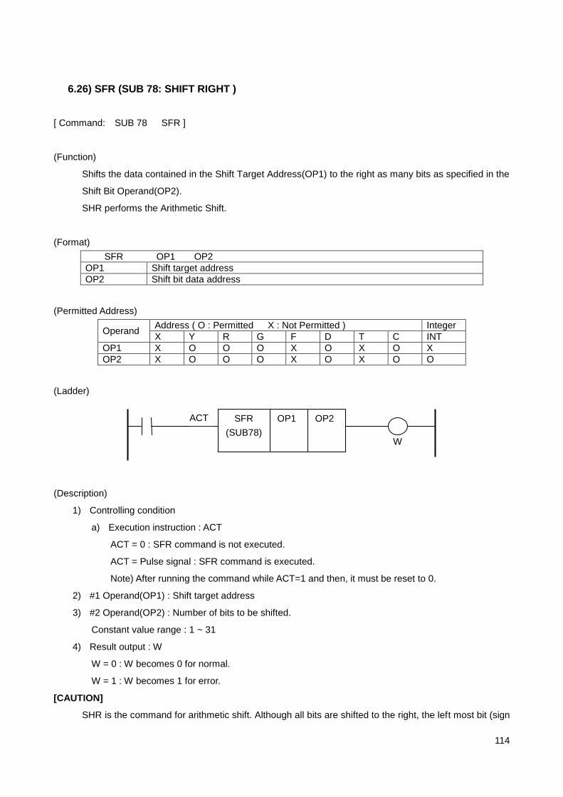
114
6.26) SFR (SUB 78: SHIFT RIGHT )
[ Command: SUB 78 SFR ]
(Function)
Shifts the data contained in the Shift Target Address(OP1) to the right as many bits as specified in the
Shift Bit Operand(OP2).
SHR performs the Arithmetic Shift.
(Format)
SFR OP1 OP2
OP1 Shift target address
OP2 Shift bit data address
(Permitted Address)
Operand Address ( O : Permitted X : Not Permitted ) Integer
X Y R G F D T C INT
OP1 X O O O X O X O X
OP2 X O O O X O X O O
(Ladder)
(Description)
1) Controlling condition
a) Execution instruction : ACT
ACT = 0 : SFR command is not executed.
ACT = Pulse signal : SFR command is executed.
Note) After running the command while ACT=1 and then, it must be reset to 0.
2) #1 Operand(OP1) : Shift target address
3) #2 Operand(OP2) : Number of bits to be shifted.
Constant value range : 1 ~ 31
4) Result output : W
W = 0 : W becomes 0 for normal.
W = 1 : W becomes 1 for error.
[CAUTION]
SHR is the command for arithmetic shift. Although all bits are shifted to the right, the left most bit (sign
SFR
(SUB78)
OP1 ACT OP2
W

115
bit) is maintained.
Example 1] 1000***00 1100***00,
Example 2] 1100***00 1110***00,
Example 3] 0100***00 0010***00

116
6.27) SFL ( SUB 79: SHIFT LEFT )
[ Command: SUB 79 SFL ]
(Function)
Shifts the data contained in the Shift Target Address(OP1) to the left as many bits as specified in the
Shift Bit Operand(OP2).
(Format)
SFL OP1 OP2
OP1 Shift target address
OP2 Shift bit data address
(Permitted Address)
Operand Address ( O : Permitted X : Not Permitted ) Integer
X Y R G F D T C INT
OP1 X O O O X O X O X
OP2 X O O O X O X O O
(Ladder)
(Description)
1) Controlling condition
a) Execution instruction : ACT
ACT = 0 : SFL command is not executed.
ACT = Pulse signal : SFL command is executed.
Note) After running the command while ACT=1 and then, it must be reset to 0.
2) #1 Operand(OP1) : Shift target address
3) #2 Operand(OP2) : Number of bits to be shifted.
Constant value range : 1 ~ 31
4) Result output : W
W = 0 : W becomes 0 for normal.
W = 1 : W becomes 1 for error.
SFL
(SUB79)
OP1 ACT OP2
W

117
3.4 HX PLC MESSAGE File Creation
3.4.1 HX PLC MESSAGE For alarms and warnings detected by PLC, they can be notified to CNC using G MAP. For this, the
PLC programmer has to write the alarm or warning message data file corresponding to G MAP and
store them to PLC folder within HX system folder.
These files are displayed to notify to the user that alarm or warning has occurred. Particularly for the
alarm that are critical to the safety such as OVER TRAVEL, special action such as inputting the
emergency signal to CNC is required.
Category G MAP Area MESSAGE DATA FILE
ALARM G900.00 ~ G949.1F PLCAlmDt.txt
WARNING G950.00 ~ G999.1F PLCOpDt.txt

118
3.4.2 ALARM MESSAGE (PLCAlmDt.txt)
ALARM MESSAGE is written to G900 ~ G949 addresses when writing PLC.
ALARM MESSAGE is prepared to notify the cause of the problem to the operator in case of the
machine problem occurrence such as the EMERGENCY-STOP or OVER TRAVEL.
ALARM MESSAGE can be recorded to the alarm list.
ALARM MESSAGE is written to PLCAlmDt.txt file for the screen display.
ALARM MESSAGE is displayed blinking on the upper part of the screen with white writing on
red background.
[Example]
Contents Description
# count „ # ‟ refers to the comments.
2 Precisely enter the number of alarm messages.
# code bit msg Address + contact bit (0~31) + alarm contents memorization status (1/0)
900 0 0 Emergency stop Ex1] 900(Blank) 0(Blank) 0(Blank) Emergency stop “G900.00 is set to HIGH, the alarm is displayed on the screen, but the PLC alarm contents is not recorded.
900 1 1 X AXIS OVER TRAVEL
Ex2] 900(Blank) 1(Blank) 1(Blank) X AXIS OVER TRAVEL “G900.01 is set to HIGH, the alarm is displayed on the screen, and the PLC alarm contents is also recorded.
-1 Use „-1‟ to mark the end of file.
Example)
# count 5 # code bit msg 900 0 0 Emergency stop. 900 9 1 X-Axis (Loading-r) + O.T. 900 10 1 Y-Axis (Loading-r) - O.T. 900 11 1 Z-Axis (Unloading-r) + O.T. 900 29 1 Short on air pressure. -1

119
3.4.3 WARNING MESSAGE (PLCOpDt.txt)
WARNING MESSAGE is written to G950 ~ G999 addresses when writing PLC.
WARNING MESSAGE is prepared notify the mishandling of the machine or current machine
status without any critical problem on the machine operation such as „Returning to the origin‟
and „Origin return is not completed‟ to the operator.
WARNING MESSAGE cannot be recorded to the alarm list.
WARNING MESSAGE is written to PLCOpDt.txt file for the screen display.
WARNING MESSAGE is displayed blinking on the bottom screen with black writing on yellow
background.
[Example]
Contents Description
# count „ # ‟ refers to the comments.
2 Precisely enter the number of warning messages.
# code bit msg Address + contact bit (0~31) + Warning Contents
950 00 Returning to origin. Ex 1] 950(Blank) 0(Blank) Returning to origin. If “G950.00 is set to HIGH, the warning is displayed on the
screen.
950 01 Origin return is not completed.
Ex2] 950(Blank) 1(Blank) Origin return is not completed. If “G950.01 is set to HIGH, the alarm is displayed on the screen.
-1 Use „-1‟ to mark the end of file.
Example)
# count 2 # code bit msg 950 0 Origin return is not completed. 950 1 Returning to origin. -1

120
4 Internal Signal
4.1 G Signal
No.
07 06 05 04 03 02 01 00
0F 0E 0D 0C 0B 0A 09 08
17 16 15 14 13 12 11 10
1F 1E 1D 1C 1B 1A 19 18
G0000
PLCRUN
NC Mode Setting Group
G0001
EDIT STEP MPG JOG ZRN DNC MDI AUTO
G0002
OVC MLK AUXL MABS DRN OPS SBK
32-Axis Extension Consideration
G0003
MLK8 MLK7 MLK6 MLK5 MLK4 MLK3 MLK2 MLK1
MLK16 MLK15 MLK14 MLK13 MLK12 MLK11 MLK10 MLK9
MLK24 MLK23 MLK22 MLK21 MLK20 MLK19 MLK18 MLK17
MLK32 MLK31 MLK30 MLK29 MLK28 MLK27 MLK26 MLK25
G0004
SKIP4 SKIP3 SKIP2 SKIP1
G0005
KLOCK
G0006
BDT8 BDT7 BDT6 BDT5 BDT4 BDT3 BDT2 BDT1
BDT9

121
No.
07 06 05 04 03 02 01 00
0F 0E 0D 0C 0B 0A 09 08
17 16 15 14 13 12 11 10
1F 1E 1D 1C 1B 1A 19 18
RESET (Emergency Stop) Group
G0008
ESP SVRS ERS
PWOFF
NC Control Signal Group
G0009
SP ST
Manual Operation Mode Group
G0011
PJ8 PJ7 PJ6 PJ5 PJ4 PJ3 PJ2 PJ1
PJ16 PJ15 PJ14 PJ13 PJ12 PJ11 PJ10 PJ9
PJ24 PJ23 PJ22 PJ21 PJ20 PJ19 PJ18 PJ17
PJ32 PJ31 PJ30 PJ29 PJ28 PJ27 PJ26 PJ25
G0012
NJ8 NJ7 NJ6 NJ5 NJ4 NJ3 NJ2 NJ1
NJ16 NJ15 NJ14 NJ13 NJ12 NJ11 NJ10 NJ9
NJ24 NJ23 NJ22 NJ21 NJ20 NJ19 NJ18 NJ17
NJ32 NJ31 NJ30 NJ29 NJ28 NJ27 NJ26 NJ25
G0013
RT MP2 MP1
G0014
MANF4 MANF3 MANF2 MANF1 MANF0
G0015
SDIST4 SDIST3 SDIST2 SDIST1 SDIST0

122
No.
07 06 05 04 03 02 01 00
0F 0E 0D 0C 0B 0A 09 08
17 16 15 14 13 12 11 10
1F 1E 1D 1C 1B 1A 19 18
G0017
MPGA8 MPGA7 MPGA6 MPGA5 MPGA4 MPGA3 MPGA2 MPGA1
MPGA16 MPGA15 MPGA14 MPGA13 MPGA12 MPGA11 MPGA10 MPGA9
MPGA24 MPGA23 MPGA22 MPGA21 MPGA20 MPGA19 MPGA18 MPGA17
MPGA32 MPGA31 MPGA30 MPGA29 MPGA28 MPGA27 MPGA26 MPGA25
G0018
MPGB8 MPGB7 MPGB6 MPGB5 MPGB4 MPGB3 MPGB2 MPGB1
MPGB16 MPGB15 MPGB14 MPGB13 MPGB12 MPGB11 MPGB10 MPGB9
MPGB24 MPGB23 MPGB22 MPGB21 MPGB20 MPGB19 MPGB18 MPGB17
MPGB32 MPGB31 MPGB30 MPGB29 MPGB28 MPGB27 MPGB26 MPGB25
G0019
MPGC8 MPGC7 MPGC6 MPGC5 MPGC4 MPGC3 MPGC2 MPGC1
MPGC16 MPGC15 MPGC14 MPGC13 MPGC12 MPGC11 MPGC10 MPGC9
MPGC24 MPGC23 MPGC22 MPGC21 MPGC20 MPGC19 MPGC18 MPGC17
MPGC32 MPGC31 MPGC30 MPGC29 MPGC28 MPGC27 MPGC26 MPGC25
G0021
MPGINTA8
MPGINTA7
MPGINTA6
MPGINTA5
MPGINTA4
MPGINTA3
MPGINTA2
MPGINTA1
MPGINTA16
MPGINTA15
MPGINTA14
MPGINTA13
MPGINTA12
MPGINTA11
MPGINTA10
MPGINTA9
MPGINTA24
MPGINTA23
MPGINTA22
MPGINTA21
MPGINTA20
MPGINTA19
MPGINTA18
MPGINTA17
MPGINTA32
MPGINTA31
MPGINTA30
MPGINTA29
MPGINTA28
MPGINTA27
MPGINTA26
MPGINTA25
G0022
MPGINTB8
MPGINTB7
MPGINTB6
MPGINTB5
MPGINTB4
MPGINTB3
MPGINTB2
MPGINTB1
MPGINTB16
MPGINTB15
MPGINTB14
MPGINTB13
MPGINTB12
MPGINTB11
MPGINTB10
MPGINTB9
MPGINTB24
MPGINTB23
MPGINTB22
MPGINTB21
MPGINTB20
MPGINTB19
MPGINTB18
MPGINTB17
MPGINTB32
MPGINTB31
MPGINTB30
MPGINTB29
MPGINTB28
MPGINTB27
MPGINTB26
MPGINTB25
G0023
MPGINTC8
MPGINTC7
MPGINTC6
MPGINTC5
MPGINTC4
MPGINTC3
MPGINTC2
MPGINTC1
MPGINTC16
MPGINTC15
MPGINTC14
MPGINTC13
MPGINTC12
MPGINTC11
MPGINTC10
MPGINTC9
MPGINTC24
MPGINTC23
MPGINTC22
MPGINTC21
MPGINTC20
MPGINTC19
MPGINTC18
MPGINTC17
MPGINTC32
MPGINTC31
MPGINTC30
MPGINTC29
MPGINTC28
MPGINTC27
MPGINTC26
MPGINTC25
Zero Return Function Group
G0025
DEC8 DEC7 DEC6 DEC5 DEC4 DEC3 DEC2 DEC1
DEC16 DEC15 DEC14 DEC13 DEC12 DEC11 DEC10 DEC9
DEC24 DEC23 DEC22 DEC21 DEC20 DEC19 DEC18 DEC17

123
DEC32 DEC31 DEC30 DEC29 DEC28 DEC27 DEC26 DEC25

124
No.
07 06 05 04 03 02 01 00
0F 0E 0D 0C 0B 0A 09 08
17 16 15 14 13 12 11 10
1F 1E 1D 1C 1B 1A 19 18
G0028
ZST8 ZST7 ZST6 ZST5 ZST4 ZST3 ZST2 ZST1
ZST16 ZST15 ZST14 ZST13 ZST12 ZST11 ZST10 ZST9
ZST24 ZST23 ZST22 ZST21 ZST20 ZST19 ZST18 ZST17
ZST32 ZST31 ZST30 ZST29 ZST28 ZST27 ZST26 ZST25
G0029
ZST208 ZST207 ZST206 ZST205 ZST204 ZST203 ZST202 ZST201
ZST216 ZST215 ZST214 ZST213 ZST212 ZST211 ZST210 ZST209
ZST224 ZST223 ZST222 ZST221 ZST220 ZST219 ZST218 ZST217
ZST232 ZST231 ZST230 ZST229 ZST228 ZST227 ZST226 ZST225
G0030
ZST308 ZST307 ZST306 ZST305 ZST304 ZST303 ZST302 ZST301
ZST316 ZST315 ZST314 ZST313 ZST312 ZST311 ZST310 ZST309
ZST324 ZST323 ZST322 ZST321 ZST320 ZST319 ZST318 ZST317
ZST332 ZST331 ZST330 ZST329 ZST328 ZST327 ZST326 ZST325
G0031
ZST408 ZST407 ZST406 ZST405 ZST404 ZST403 ZST402 ZST401
ZST416 ZST415 ZST414 ZST413 ZST412 ZST411 ZST410 ZST409
ZST424 ZST423 ZST422 ZST421 ZST420 ZST419 ZST418 ZST417
ZST432 ZST431 ZST430 ZST429 ZST428 ZST427 ZST426 ZST425
External Manipulation Signal Group
G0036
RTOVR4 RTOVR3 RTOVR2 RTOVR1 RTOVR0
G0037
FDOVR4 FDOVR3 FDOVR2 FDOVR1 FDOVR0
G0038
SPOVR4 SPOVR3 SPOVR2 SPOVR1 SPOVR0

125
No.
07 06 05 04 03 02 01 00
0F 0E 0D 0C 0B 0A 09 08
17 16 15 14 13 12 11 10
1F 1E 1D 1C 1B 1A 19 18
G0039
NIT PIT
RVS
G0040
PIT8 PIT7 PIT6 PIT5 PIT4 PIT3 PIT2 PIT1
PIT16 PIT15 PIT14 PIT13 PIT12 PIT11 PIT10 PIT9
PIT24 PIT23 PIT22 PIT21 PIT20 PIT19 PIT18 PIT17
PIT32 PIT31 PIT30 PIT29 PIT28 PIT27 PIT26 PIT25
G0041
NIT8 NIT7 NIT6 NIT5 NIT4 NIT3 NIT2 NIT1
NIT16 NIT15 NIT14 NIT13 NIT12 NIT11 NIT10 NIT9
NIT24 NIT23 NIT22 NIT21 NIT20 NIT19 NIT18 NIT17
NIT32 NIT31 NIT30 NIT29 NIT28 NIT27 NIT26 NIT25
G0043
CLOFF8 CLOFF7 CLOFF6 CLOFF5 CLOFF4 CLOFF3 CLOFF2 CLOFF1
CLOFF16 CLOFF15 CLOFF14 CLOFF13 CLOFF12 CLOFF11 CLOFF10 CLOFF9
CLOFF24 CLOFF23 CLOFF22 CLOFF21 CLOFF20 CLOFF19 CLOFF18 CLOFF17
CLOFF32 CLOFF31 CLOFF30 CLOFF29 CLOFF28 CLOFF27 CLOFF26 CLOFF25
G0044
SVOFF8 SVOFF7 SVOFF6 SVOFF5 SVOFF4 SVOFF3 SVOFF2 SVOFF1
SVOFF16 SVOFF15 SVOFF14 SVOFF13 SVOFF12 SVOFF11 SVOFF10 SVOFF9
SVOFF24 SVOFF23 SVOFF22 SVOFF21 SVOFF20 SVOFF19 SVOFF18 SVOFF17
SVOFF32 SVOFF31 SVOFF30 SVOFF29 SVOFF28 SVOFF27 SVOFF26 SVOFF25
G0045
MIR8 MIR7 MIR6 MIR5 MIR4 MIR3 MIR2 MIR1
MIR16 MIR15 MIR14 MIR13 MIR12 MIR11 MIR10 MIR9
MIR24 MIR23 MIR22 MIR21 MIR20 MIR19 MIR18 MIR17
MIR32 MIR31 MIR30 MIR29 MIR28 MIR27 MIR26 MIR25
G0046
TPRS

126
No.
07 06 05 04 03 02 01 00
0F 0E 0D 0C 0B 0A 09 08
17 16 15 14 13 12 11 10
1F 1E 1D 1C 1B 1A 19 18
G0047
PSLDS8 PSLDS7 PSLDS6 PSLDS5 PSLDS4 PSLDS3 PSLDS2 PSLDS1
PSLDS16 PSLDS15 PSLDS14 PSLDS13 PSLDS12 PSLDS11 PSLDS10 PSLDS9
PSLDS24 PSLDS23 PSLDS22 PSLDS21 PSLDS20 PSLDS19 PSLDS18 PSLDS17
PSLDS32 PSLDS31 PSLDS30 PSLDS29 PSLDS28 PSLDS27 PSLDS26 PSLDS25
G0048
NSLDS8 NSLDS7 NSLDS6 NSLDS5 NSLDS4 NSLDS3 NSLDS2 NSLDS1
NSLDS16 NSLDS15 NSLDS14 NSLDS13 NSLDS12 NSLDS11 NSLDS10 NSLDS9
NSLDS24 NSLDS23 NSLDS22 NSLDS21 NSLDS20 NSLDS19 NSLDS18 NSLDS17
NSLDS32 NSLDS31 NSLDS30 NSLDS29 NSLDS28 NSLDS27 NSLDS26 NSLDS25
G0049
EDECP8 EDECP7 EDECP6 EDECP5 EDECP4 EDECP3 EDECP2 EDECP1
EDECP16 EDECP15 EDECP14 EDECP13 EDECP12 EDECP11 EDECP10 EDECP9
EDECP24 EDECP23 EDECP22 EDECP21 EDECP20 EDECP19 EDECP18 EDECP17
EDECP32 EDECP31 EDECP30 EDECP29 EDECP28 EDECP27 EDECP26 EDECP25
G0050
EDECN8 EDECN7 EDECN6 EDECN5 EDECN4 EDECN3 EDECN2 EDECN1
EDECN16 EDECN15 EDECN14 EDECN13 EDECN12 EDECN11 EDECN10 EDECN9
EDECN24 EDECN23 EDECN22 EDECN21 EDECN20 EDECN19 EDECN18 EDECN17
EDECN32 EDECN31 EDECN30 EDECN29 EDECN28 EDECN27 EDECN26 EDECN25
Axis Setting Group
G0052
SPNO5 SPNO4 SPNO3 SPNO2 SPNO1 SPNO0
G0053
ZNO5 ZNO4 ZNO3 ZNO2 ZNO1 ZNO0
M Function Group
G0056
MFIN

127
No.
07 06 05 04 03 02 01 00
0F 0E 0D 0C 0B 0A 09 08
17 16 15 14 13 12 11 10
1F 1E 1D 1C 1B 1A 19 18
S Function Group
G0064
GR4 GR3 GR2 GR1 SFIN
GRST
G0065
SPRPM4 SPRPM3 SPRPM2 SPRPM1 SPRPM0
G0066
DSPOS DSOR DSPCCW DSPCW DSSTP
SPOS SZAR SAR SOR SPCCW SPCW SSTP
G0067
SSC
T Function Group
G0075
TFIN
G0079
TLRTN TLESC
G0080
TSDC TCDCN TCDCP TDCDIS
TLRTN TLESC

128
No.
07 06 05 04 03 02 01 00
0F 0E 0D 0C 0B 0A 09 08
17 16 15 14 13 12 11 10
1F 1E 1D 1C 1B 1A 19 18
G0081
TMP7 TMP6 TMP5 TMP4 TMP3 TMP2 TMP1 TMP0
TMP15 TMP14 TMP13 TMP12 TMP11 TMP10 TMP9 TMP8
G0082
TG1D7 TG1D6 TG1D5 TG1D4 TG1D3 TG1D2 TG1D1 TG1D0
TG1D15 TG1D14 TG1D13 TG1D12 TG1D11 TG1D10 TG1D9 TG1D8
G0083
TG2D7 TG2D6 TG2D5 TG2D4 TG2D3 TG2D2 TG2D1 TG2D0
TG2D15 TG2D14 TG2D13 TG2D12 TG2D11 TG2D10 TG2D9 TG2D8
G0090
CHPSP CHPST
CHPOVR
3 CHPOVR
2 CHPOVR
1 CHPOVR
0
Synchronization Control Group
G0103
TWNCTRL8
TWNCTRL7
TWNCTRL6
TWNCTRL5
TWNCTRL4
TWNCTRL3
TWNCTRL2
TWNCTRL1
TWNCTRL16
TWNCTRL15
TWNCTRL14
TWNCTRL13
TWNCTRL12
TWNCTRL11
TWNCTRL10
TWNCTRL9
TWNCTRL24
TWNCTRL23
TWNCTRL22
TWNCTRL21
TWNCTRL20
TWNCTRL19
TWNCTRL18
TWNCTRL17
TWNCTRL32
TWNCTRL31
TWNCTRL30
TWNCTRL29
TWNCTRL28
TWNCTRL27
TWNCTRL26
TWNCTRL25
Custom Macro
G0115
UI007 UI006 UI005 UI004 UI003 UI002 UI001 UI000
UI015 UI014 UI013 UI012 UI011 UI010 UI009 UI008
UI023 UI022 UI021 UI020 UI019 UI018 UI017 UI016
UI031 UI030 UI029 UI028 UI027 UI026 UI025 UI024
G0116
UI107 UI106 UI105 UI104 UI103 UI102 UI101 UI100
UI115 UI114 UI113 UI112 UI111 UI110 UI109 UI108
UI123 UI122 UI121 UI120 UI119 UI118 UI117 UI116
UI131 UI130 UI129 UI128 UI127 UI126 UI125 UI124

129
No.
07 06 05 04 03 02 01 00
0F 0E 0D 0C 0B 0A 09 08
17 16 15 14 13 12 11 10
1F 1E 1D 1C 1B 1A 19 18
G0117
UI207 UI206 UI205 UI204 UI203 UI202 UI201 UI200
UI215 UI214 UI213 UI212 UI211 UI210 UI209 UI208
UI223 UI222 UI221 UI220 UI219 UI218 UI217 UI216
UI231 UI230 UI229 UI228 UI227 UI226 UI225 UI224
G0118
UI307 UI306 UI305 UI304 UI303 UI302 UI301 UI300
UI315 UI314 UI313 UI312 UI311 UI310 UI309 UI308
UI323 UI322 UI321 UI320 UI319 UI318 UI317 UI316
UI331 UI330 UI329 UI328 UI327 UI326 UI325 UI324
PLC Control-Axis Group
G0120
PX_ST8 PX_ST7 PX_ST6 PX_ST5 PX_ST4 PX_ST3 PX_ST2 PX_ST1
PX_ST16 PX_ST15 PX_ST14 PX_ST13 PX_ST12 PX_ST11 PX_ST10 PX_ST9
PX_ST24 PX_ST23 PX_ST22 PX_ST21 PX_ST20 PX_ST19 PX_ST18 PX_ST17
PX_ST32 PX_ST31 PX_ST30 PX_ST29 PX_ST28 PX_ST27 PX_ST26 PX_ST25
G0121
PX_CAN8 PX_CAN7 PX_CAN6 PX_CAN5 PX_CAN4 PX_CAN3 PX_CAN2 PX_CAN1
PX_CAN16
PX_CAN15
PX_CAN14
PX_CAN13
PX_CAN12
PX_CAN11
PX_CAN10
PX_CAN9
PX_CAN24
PX_CAN23
PX_CAN22
PX_CAN21
PX_CAN20
PX_CAN19
PX_CAN18
PX_CAN17
PX_CAN32
PX_CAN31
PX_CAN30
PX_CAN29
PX_CAN28
PX_CAN27
PX_CAN26
PX_CAN25
G0123
PX_MF8 PX_MF7 PX_MF6 PX_MF5 PX_MF4 PX_MF3 PX_MF2 PX_MF1
PX_MF16 PX_MF15 PX_MF14 PX_MF13 PX_MF12 PX_MF11 PX_MF10 PX_MF9
PX_MF24 PX_MF23 PX_MF22 PX_MF21 PX_MF20 PX_MF19 PX_MF18 PX_MF17
PX_MF32 PX_MF31 PX_MF30 PX_MF29 PX_MF28 PX_MF27 PX_MF26 PX_MF25
G0124
PX_MO8 PX_MO7 PX_MO6 PX_MO5 PX_MO4 PX_MO3 PX_MO2 PX_MO1
PX_MO16 PX_MO15 PX_MO14 PX_MO13 PX_MO12 PX_MO11 PX_MO10 PX_MO9
PX_MO24 PX_MO23 PX_MO22 PX_MO21 PX_MO20 PX_MO19 PX_MO18 PX_MO17
PX_MO32 PX_MO31 PX_MO30 PX_MO29 PX_MO28 PX_MO27 PX_MO26 PX_MO25
G0125
PX_INPS8
PX_INPS7
PX_INPS6
PX_INPS5
PX_INPS4
PX_INPS3
PX_INPS2
PX_INPS1
PX_INPS16
PX_INPS15
PX_INPS14
PX_INPS13
PX_INPS12
PX_INPS11
PX_INPS10
PX_INPS9
PX_INPS24
PX_INPS23
PX_INPS22
PX_INPS21
PX_INPS20
PX_INPS19
PX_INPS18
PX_INPS17

130
PX_INPS32
PX_INPS31
PX_INPS30
PX_INPS29
PX_INPS28
PX_INPS27
PX_INPS26
PX_INPS25

131
No.
07 06 05 04 03 02 01 00
0F 0E 0D 0C 0B 0A 09 08
17 16 15 14 13 12 11 10
1F 1E 1D 1C 1B 1A 19 18
G0131
PX_BLK1
G0132
PX_FO1
PX_BLK2 : G0133, PX_BLK3 : G0135, … , PX_BLK32 : G0193 ( PX_BLK(n) : G(0129 + 2n) )
PX_FO2 : G0134, PX_BLK3 : G0136, … , PX_BLK32 : G0194 ( PX_BLK(n) : G(0130 + 2n) )
N refers to the axis number.
If you select #5 axis as the PLC axis, PX_BLK5 becomes G0139 and PX_FO5 becomes G0140.
Special Control Group
Z Gap Trace
G0200
ZGTRC4 ZGTRC3 ZGTRC2 ZGTRC1
ZGFAR4 ZGFAR3 ZGFAR2 ZGFAR1
Punch Press
G0201
PPMF PPMM PPFW PPFS
PPMTC PPMP2 PPMP1
NPFIN PPFIN PPE
Screen Information Group
G3004
SCR7 SCR6 SCR5 SCR4 SCR3 SCR2 SCR1 SCR0
G3005
STRANS

132
4.2 F Signal
No.
07 06 05 04 03 02 01 00
0F 0E 0D 0C 0B 0A 09 08
17 16 15 14 13 12 11 10
1F 1E 1D 1C 1B 1A 19 18
Preparation Completion Group
F0000
SA MA
NC Mode Setting Group
F0001
EDITL STEPL MPGL JOGL ZRNL DNCL MDIL AUTOL
F0002
F0003
F0004
RESET (Emergency Stop) Group
F0006
RSTK RST
NC Control Group
F0007
SCST

133
No.
07 06 05 04 03 02 01 00
0F 0E 0D 0C 0B 0A 09 08
17 16 15 14 13 12 11 10
1F 1E 1D 1C 1B 1A 19 18
NC Status Group
F0008
OP SPL STL
Zero Return Function Group
F0016
ZR8 ZR7 ZR6 ZR5 ZR4 ZR3 ZR2 ZR1
ZR16 ZR15 ZR14 ZR13 ZR12 ZR11 ZR10 ZR9
ZR24 ZR23 ZR22 ZR21 ZR20 ZR19 ZR18 ZR17
ZR32 ZR31 ZR30 ZR29 ZR28 ZR27 ZR26 ZR25
F0017
ZF8 ZF7 ZF6 ZF5 ZF4 ZF3 ZF2 ZF1
ZF16 ZF15 ZF14 ZF13 ZF12 ZF11 ZF10 ZF9
ZF24 ZF23 ZF22 ZF21 ZF20 ZF19 ZF18 ZF17
ZF32 ZF31 ZF30 ZF29 ZF28 ZF27 ZF26 ZF25
F0018
ZP8 ZP7 ZP6 ZP5 ZP4 ZP3 ZP2 ZP1
ZP16 ZP15 ZP14 ZP13 ZP12 ZP11 ZP10 ZP9
ZP24 ZP23 ZP22 ZP21 ZP20 ZP19 ZP18 ZP17
ZP32 ZP31 ZP30 ZP29 ZP28 ZP27 ZP26 ZP25
F0019
ZP208 ZP207 ZP206 ZP205 ZP204 ZP203 ZP202 ZP201
ZP216 ZP215 ZP214 ZP213 ZP212 ZP211 ZP210 ZP209
ZP224 ZP223 ZP222 ZP221 ZP220 ZP219 ZP218 ZP217
ZP232 ZP231 ZP230 ZP229 ZP228 ZP227 ZP226 ZP225
F0020
ZP308 ZP307 ZP306 ZP305 ZP304 ZP303 ZP302 ZP301
ZP316 ZP315 ZP314 ZP313 ZP312 ZP311 ZP310 ZP309
ZP324 ZP323 ZP322 ZP321 ZP320 ZP319 ZP318 ZP317
ZP332 ZP331 ZP330 ZP329 ZP328 ZP327 ZP326 ZP325
F0021
ZP408 ZP407 ZP406 ZP405 ZP404 ZP403 ZP402 ZP401
ZP416 ZP415 ZP414 ZP413 ZP412 ZP411 ZP410 ZP409
ZP424 ZP423 ZP422 ZP421 ZP420 ZP419 ZP418 ZP417
ZP432 ZP431 ZP430 ZP429 ZP428 ZP427 ZP426 ZP425

134
No.
07 06 05 04 03 02 01 00
0F 0E 0D 0C 0B 0A 09 08
17 16 15 14 13 12 11 10
1F 1E 1D 1C 1B 1A 19 18
F0022
ZDSP8 ZDSP7 ZDSP6 ZDSP5 ZDSP4 ZDSP3 ZDSP2 ZDSP1
ZDSP16 ZDSP15 ZDSP14 ZDSP13 ZDSP12 ZDSP11 ZDSP10 ZDSP9
ZDSP24 ZDSP23 ZDSP22 ZDSP21 ZDSP20 ZDSP19 ZDSP18 ZDSP17
ZDSP32 ZDSP31 ZDSP30 ZDSP29 ZDSP28 ZDSP27 ZDSP26 ZDSP25
External Manipulation Signal Group
F0028
SVRDY8 SVRDY 7 SVRDY 6 SVRDY 5 SVRDY 4 SVRDY 3 SVRDY 2 SVRDY 1
SVRDY16 SVRDY15 SVRDY
14 SVRDY
13 SVRDY
12 SVRDY
11 SVRDY10 SVRDY 9
SVRDY24 SVRDY
23 SVRDY
22 SVRDY
21 SVRDY
20 SVRDY
19 SVRDY
18 SVRDY
17
SVRDY 32
SVRDY 31
SVRDY 30
SVRDY 29
SVRDY 28
SVRDY 27
SVRDY 26
SVRDY 25
F0029
MIRL8 MIRL7 MIRL6 MIRL5 MIRL4 MIRL3 MIRL2 MIRL1
MIRL16 MIRL15 MIRL14 MIRL13 MIRL12 MIRL11 MIRL10 MIRL9
MIRL24 MIRL23 MIRL22 MIRL21 MIRL20 MIRL19 MIRL18 MIRL17
MIRL32 MIRL31 MIRL30 MIRL29 MIRL28 MIRL27 MIRL26 MIRL25
F0030
RVSL
Axis-Setting Group
F0033
SPNOL5 SPNOL4 SPNOL3 SPNOL2 SPNOL1 SPNOL0
F0034
ZNOL5 ZNOL4 ZNOL3 ZNOL2 ZNOL1 ZNOL0
M Function Group
F0037
MDEN MF
DM30 DM02 DM01 DM00

135
No.
07 06 05 04 03 02 01 00
0F 0E 0D 0C 0B 0A 09 08
17 16 15 14 13 12 11 10
1F 1E 1D 1C 1B 1A 19 18
F0038
M7 M6 M5 M4 M3 M2 M1 M0
M15 M14 M13 M12 M11 M10 M9 M8
M23 M22 M21 M20 M19 M18 M17 M16
M31 M30 M29 M28 M27 M26 M25 M24
S Function Group
F0045
SDEN SF
F0046
S7 S6 S5 S4 S3 S2 S1 S0
S15 S14 S13 S12 S11 S10 S9 S8
S23 S22 S21 S20 S19 S18 S17 S16
S31 S30 S29 S28 S27 S26 S25 S24
F0047
SRPMB7 SRPMB6 SRPMB5 SRPMB4 SRPMB3 SRPMB2 SRPMB1 SRPMB0
SRPMB15
SRPMB14
SRPMB13
SRPMB12
SRPMB11
SRPMB10
SRPMB9 SRPMB8
SRPMB23
SRPMB22
SRPMB21
SRPMB20
SRPMB19
SRPMB18
SRPMB17
SRPMB16
SRPMB31
SRPMB30
SRPMB29
SRPMB28
SRPMB27
SRPMB26
SRPMB25
SRPMB24
F0048
SPOSST SZARST SARST SORST SPCCWS
T SPCWST SSTPST
F0049
GRSFT GRS4 GRS3 GRS2 GRS1
F0050
SSCL

136
No.
07 06 05 04 03 02 01 00
0F 0E 0D 0C 0B 0A 09 08
17 16 15 14 13 12 11 10
1F 1E 1D 1C 1B 1A 19 18
T Function Group
F0061
TDEN TF
F0062
T7 T6 T5 T4 T3 T2 T1 T0
T15 T14 T13 T12 T11 T10 T9 T8
T23 T22 T21 T20 T19 T18 T17 T16
T31 T30 T29 T28 T27 T26 T25 T24
F0064
TLRTNL TLESCL TLMODL
F0065
TGDC TDCNAK TDCFIN
TCTP3 TCTP2 TCTP1 TSTP3 TSTP2 TSTP1
TALN TALT TPALN TPALT
F0066
TTP7 TTP6 TTP5 TTP4 TTP3 TTP2 TTP1 TTP0
TTP15 TTP14 TTP13 TTP12 TTP11 TTP10 TTP9 TTP8
F0067
TSP7 TSP6 TSP5 TSP4 TSP3 TSP2 TSP1 TSP0
TSP15 TSP14 TSP13 TSP12 TSP11 TSP10 TSP9 TSP8
F0068
TCP7 TCP6 TCP5 TCP4 TCP3 TCP2 TCP1 TCP0
TCP15 TCP14 TCP13 TCP12 TCP11 TCP10 TCP9 TCP8

137
No.
07 06 05 04 03 02 01 00
0F 0E 0D 0C 0B 0A 09 08
17 16 15 14 13 12 11 10
1F 1E 1D 1C 1B 1A 19 18
F0075
CHPL
NC Internal Information Group
F0084
MV8 MV7 MV6 MV5 MV4 MV3 MV2 MV1
MV16 MV15 MV14 MV13 MV12 MV11 MV10 MV9
MV24 MV23 MV22 MV21 MV20 MV19 MV18 MV17
MV32 MV31 MV30 MV29 MV28 MV27 MV26 MV25
F0085
PMV8 PMV7 PMV6 PMV5 PMV4 PMV3 PMV2 PMV1
PMV16 PMV15 PMV14 PMV13 PMV12 PMV11 PMV10 PMV9
PMV24 PMV23 PMV22 PMV21 PMV20 PMV19 PMV18 PMV17
PMV32 PMV31 PMV30 PMV29 PMV28 PMV27 PMV26 PMV25
F0086
NMV8 NMV7 NMV6 NMV5 NMV4 NMV3 NMV2 NMV1
NMV16 NMV15 NMV14 NMV13 NMV12 NMV11 NMV10 NMV9
NMV24 NMV23 NMV22 NMV21 NMV20 NMV19 NMV18 NMV17
NMV32 NMV31 NMV30 NMV29 NMV28 NMV27 NMV26 NMV25
F0087
INP8 INP7 INP6 INP5 INP4 INP3 INP2 INP1
INP16 INP15 INP14 INP13 INP12 INP11 INP10 INP9
INP24 INP23 INP22 INP21 INP20 INP19 INP18 INP17
INP32 INP31 INP30 INP29 INP28 INP27 INP26 INP25
F0090
PASL8 PASL7 PASL6 PASL5 PASL4 PASL3 PASL2 PASL1
PASL16 PASL15 PASL14 PASL13 PASL12 PASL11 PASL10 PASL9
PASL24 PASL23 PASL22 PASL21 PASL20 PASL19 PASL18 PASL17
PASL32 PASL31 PASL30 PASL29 PASL28 PASL27 PASL26 PASL25
F0091
CASL8 CASL7 CASL6 CASL5 CASL4 CASL3 CASL2 CASL1
CASL16 CASL15 CASL14 CASL13 CASL12 CASL11 CASL10 CASL9
CASL24 CASL23 CASL22 CASL21 CASL20 CASL19 CASL18 CASL17
CASL32 CASL31 CASL30 CASL29 CASL28 CASL27 CASL26 CASL25

138
No.
07 06 05 04 03 02 01 00
0F 0E 0D 0C 0B 0A 09 08
17 16 15 14 13 12 11 10
1F 1E 1D 1C 1B 1A 19 18
F0092
NASL8 NASL7 NASL6 NASL5 NASL4 NASL3 NASL2 NASL1
NASL16 NASL15 NASL14 NASL13 NASL12 NASL11 NASL10 NASL9
NASL24 NASL23 NASL22 NASL21 NASL20 NASL19 NASL18 NASL17
NASL32 NASL31 NASL30 NASL29 NASL28 NASL27 NASL26 NASL25
F0099
RTAP THRD CSS CP PTP
HSM
Custom Macro
F0105
UO007 UO006 UO005 UO004 UO003 UO002 UO001 UO000
UO015 UO014 UO013 UO012 UO011 UO010 UO009 UO008
UO023 UO022 UO021 UO020 UO019 UO018 UO017 UO016
UO031 UO030 UO029 UO028 UO027 UO026 UO025 UO024
F0106
UO107 UO106 UO105 UO104 UO103 UO102 UO101 UO100
UO115 UO114 UO113 UO112 UO111 UO110 UO109 UO108
UO123 UO122 UO121 UO120 UO119 UO118 UO117 UO116
UO131 UO130 UO129 UO128 UO127 UO126 UO125 UO124
F0107
UO207 UO206 UO205 UO204 UO203 UO202 UO201 UO200
UO215 UO214 UO213 UO212 UO211 UO210 UO209 UO208
UO223 UO222 UO221 UO220 UO219 UO218 UO217 UO216
UO231 UO230 UO229 UO228 UO227 UO226 UO225 UO224
F0108
UO307 UO306 UO305 UO304 UO303 UO302 UO301 UO300
UO315 UO314 UO313 UO312 UO311 UO310 UO309 UO308
UO323 UO322 UO321 UO320 UO319 UO318 UO317 UO316
UO331 UO330 UO329 UO328 UO327 UO326 UO325 UO324

139
No.
07 06 05 04 03 02 01 00
0F 0E 0D 0C 0B 0A 09 08
17 16 15 14 13 12 11 10
1F 1E 1D 1C 1B 1A 19 18
PLC Control-Axis Group
F0110
PX_FIN8 PX_FIN7 PX_FIN6 PX_FIN5 PX_FIN4 PX_FIN3 PX_FIN2 PX_FIN1
PX_FIN16 PX_FIN15 PX_FIN14 PX_FIN13 PX_FIN12 PX_FIN11 PX_FIN10 PX_FIN9
PX_FIN24 PX_FIN23 PX_FIN22 PX_FIN21 PX_FIN20 PX_FIN19 PX_FIN18 PX_FIN17
PX_FIN32 PX_FIN31 PX_FIN30 PX_FIN29 PX_FIN28 PX_FIN27 PX_FIN26 PX_FIN25
F0111
PX_NAK8 PX_NAK7 PX_NAK6 PX_NAK5 PX_NAK4 PX_NAK3 PX_NAK2 PX_NAK1
PX_NAK16
PX_NAK15
PX_NAK14
PX_NAK13
PX_NAK12
PX_NAK11
PX_NAK10
PX_NAK9
PX_NAK24
PX_NAK23
PX_NAK22
PX_NAK21
PX_NAK20
PX_NAK19
PX_NAK18
PX_NAK17
PX_NAK32
PX_NAK31
PX_NAK30
PX_NAK29
PX_NAK28
PX_NAK27
PX_NAK26
PX_NAK25
F0121
PX_POS1
PX_POS2 : F0123, PX_POS3 : F0125, … , PX_POS32 : F0183 ( PX_POS(n) : F(0119 + 2n) )
N refers to the axis number.
If you set #5 axis as the PLC axis, PX_BPOS5 becomes F0129.

140
No.
07 06 05 04 03 02 01 00
0F 0E 0D 0C 0B 0A 09 08
17 16 15 14 13 12 11 10
1F 1E 1D 1C 1B 1A 19 18
Special Control Group
Z Gap Trace / Feed Speed Output
F0200
ZGTRCL4 ZGTRCL3 ZGTRCL2 ZGTRCL1
MVCF
F0201
MVFO7 MVFO6 MVFO5 MVFO4 MVFO3 MVFO2 MVFO1 MVFO0
MVFO15 MVFO14 MVFO13 MVFO12 MVFO11 MVFO10 MVFO9 MVFO8
MVFO23 MVFO22 MVFO21 MVFO20 MVFO19 MVFO18 MVFO17 MVFO16
MVFO31 MVFO30 MVFO29 MVFO28 MVFO27 MVFO26 MVFO25 MVFO24
Punch Press
F0202
NPF PPF
Key Group
F3000
KEY7 KEY6 KEY5 KEY4 KEY3 KEY2 KEY1 KEY0
KEY15 KEY14 KEY13 KEY12 KEY11 KEY10 KEY9 KEY8
KEY23 KEY22 KEY21 KEY20 KEY19 KEY18 KEY17 KEY16
KEY31 KEY30 KEY29 KEY28 KEY27 KEY26 KEY25 KEY24
F3001
KEY39 KEY38 KEY37 KEY36 KEY35 KEY34 KEY33 KEY32
KEY47 KEY46 KEY45 KEY44 KEY43 KEY42 KEY41 KEY40
KEY55 KEY54 KEY53 KEY52 KEY51 KEY50 KEY49 KEY48
KEY63 KEY62 KEY61 KEY60 KEY59 KEY58 KEY57 KEY56
Screen Information Group
F3004
SCRL7 SCRL6 SCRL5 SCRL4 SCRL3 SCRL2 SCRL1 SCRL0
F3005
SCFIN

141
4.3 PLC Signal Index
No Func. PLC -> CNC PLC <- CNC
Description Symbol G MAP Symbol F MAP
1 READ
Y
PLCRUN
G0.00 PLC is in normal operation.
MA F0.00
ON if there is no problem on CNC. On if the self-diagnosis is successfully completed after powering on the controller. Off, when any error is found in the controller such as CPU or memory error.
SA F0.01 ON when there is no problem on Servo/Spindle side. During EM-STOP, Servo OFF, Servo Alarm.
2
NC Mode Settin
g (Defau
lt)
CNC Operation Mode (Interlock to G/F Map)
AUTO G1.00 AUTOL F1.10 AUTO Mode Selection/Confirmation Signal
MDI G1.01 MDIL F1.11 MDI(Manual Data Input) Mode Selection/Confirmation Signal
DNC G1.02 DNCL F1.12 DNC Mode Selection/Confirmation Signal
ZRN G1.03 ZRNL F1.13 Zero Return Mode Selection/Confirmation Signal
JOG G1.04 JOGL F1.14 JOG Mode Selection/Confirmation Signal
MPG G1.05 MPGL F1.15 HAND WHEEL(MPG) Mode Selection/Confirmation Signal
STEP G1.06 STEPL F1.16 STEP Mode Selection/Confirmation Signal
EDIT G1.07 EDITL F1.17 EDIT Mode Selection/Confirmation Signal
3
NC Mode Settin
g (Complement
ary)
SBK G2.00 Single Block
OPS G2.01 Optional Block Stop
DRN G2.02 Dry Run
MABS G2.03 Manual Absolute Mode
AUXL G2.04 Multi-Step Optional Block Skip
MLK G2.06 All Axis Machine Lock
MLK1 ~ MLK32
G3.00~ G3.1F
Per Axis Machine Lock
BDT1 ~ BDT9
G6.00~ G6.08
M/S/T Code Lock (Auxiliary Function Lock : AFL)
OVC G2.07 Override Cancel
KLOCK G5.00 Memory Protection, Key/Edit Protection
SKIP1 ~ SKIP4
G4.00~ G4.03
Multi-Step SKIP Signal
4
Reset
EMG-STOP
ERS G8.00 RST F6.00
External Reset Instruction/Status Signal (Initializes NC State.)
RSTK F6.01 Reset key on MDI board is ON
SVRS G8.01 Servo Alarm Reset.
ESP G8.02 Emergency-Stop Signal
PWOFF G8.08 POWER OFF Signal
5
NC Contro
l Signal
ST G9.00 Cycle Start
SP G9.02 Feed Hold (Feed Stop)
SCST F7.00 Scheduling Function Cycle Start Signal
6 NC
State
STL F8.00 AUTO Mode Operation in progress.
SPL F8.01 AUTO Mode Operation in Idle.
OP F8.02 AUTO Mode Operation in progress.

142
No Func. PLC -> CNC PLC <- CNC
Description Symbol G MAP Symbol F MAP
7
Manual
Operation
Mode
PJ1 ~ PJ32
G11.00~ G11.1F
JOG Feeding in + Direction (32-Axis)
NJ1 ~ NJ32
G12.00~ G12.1F
JOG Feeding in – Direction (32-Axis)
RT G13.04 Rapid JOG Feeding ON/OFF
MANF0 ~ MANF4
G14.00~ G14.04
Manual Feed Speed Table Index (Refer to Parameter)
SDIST0 ~ SDIST4
G15.00~ G15.04
Step Feed Dist. Table Index (Refer to Parameter)
MP1, MP2
G13.00 G13.01
MPG Multiplier (X1, X10, X100)
MPGA1 ~ MPGA32
G17.00~ G17.1F
Manual Feeding Axis Selection by the #1 MPG
MPGB1 ~ MPGB32
G18.00~ G18.1F
Manual Feeding Axis Selection by the #2 MPG
MPGC1 ~ MPGC32
G19.00~ G19.1F
Manual Feeding Axis Selection by the #3 MPG
MPGINTA1~MPGINTA32
G21.00~ G21.1F
Manual Feeding Axis Selection by the #1 MPG Interrupt
MPGINTB1~MPGINTB32
G22.00~ G22.1F
Manual Feeding Axis Selection by the #2 MPG Interrupt
MPGINTC1~MPGINTC32
G23.00~ G23.1F
Manual Feeding Axis Selection by the #3 MPG Interrupt
8
Zero Return Functi
on
DEC1~ DEC32
G25.00~ G25.1F
Zero Return Decel. Dog Switch Recognition Signal
ZR1~ ZR32
F16.00~ F16.1F
Zero Return in progress.
ZF1~ ZF32
F17.00~ F17.1F
Zero Return Completion Signal (Maintained as High after the Zero Return)
ZP1~ ZP32
F18.00~ F18.1F
Signal within the #1 Zero Return segment Signal within the
Zero Return segment (Off, when moving out of Zero position segment. This signal works even if Zero Return is not performed.
ZP201~ ZP232
F19.00~ F19.1F
Signal within the #2 Zero Return segment
ZP301 ~ ZP332
F20.00~ F20.1F
Signal within the #3 Zero Return segment
ZP401 ~ ZP432
F21.00~ F21.1F
Signal within the #4 Zero Return segment
ZST1 ~ ZST32
G28.00~ G28.1F
#1 Zero Return Start Signal
ZST201 ~ ZST232
G29.00~ G29.1F
#2 Zero Return Start Signal
ZST301 ~ ZST332
G30.00~ G30.1F
#3 Zero Return Start Signal
ZST401 ~ ZST432
G31.00~ G31.1F
#4 Zero Return Start Signal

143
ZDSP1 ~ ZDSP32
F22.00~ F22.1F
No Zero Return Area Signal

144
No
Func. PLC -> CNC PLC <- CNC
Description Symbol G MAP Symbol F MAP
9
External
Control
Signal
PIT G39.00 Interlock for all axis in + direction
PIT1 ~ PIT32
G40.00~ G40.1F
Per Axis Interlock in + direction
NIT G39.01 Interlock for all axis in - direction
NIT1 ~NIT32
G41.00~ G41.1F
Per Axis Interlock in - direction
CLOFF1~ CLOFF32
G43.00~ G43.1F
Servo OFF the corresponding axis and ignores all instruction and alarm, but Encoder Feed Back.
SVOFF1~ SVOFF32
G44.00~ G44.1F
Servo OFF the corresponding axis (SA signal [F0.01] is maintained)
SVRDY1~ SVRDY32
F28.00~F28.1F
Per Axis Servo READY State
MIR1 ~ MIR32
G45.00~ G45.1F
Mirror Image Signal Axis Feed Direction by AUTO, MDI operation is opposite of instruction.
MIRL1 ~ MIRL32
F29.00~F29.1F
Mirror Image Confirmation Signal
RTOVR0 ~ RTOVR4
G36.00~ G36.04
Rapid Feed Override Mapping to system table of 32 Override Factors
FDOVR0 ~ FDOVR4
G37.00~ G37.04
Feed Override, Mapping to system table of 32 Override Factors
SPOVR0 ~ SPOVR4
G38.00~ G38.04
Spindle Override, Mapping to system table of 32 Override Factors
RVS G39.08 RVSL F30.08 Reverse Operation Start Signal / Reverse Operation in
Progress Signal
TPRS G46.00 Input Compensation Input Mode Selection Signal
PSLDS1~ PSLDS32
G47.00~ G47.1F
Soft Limit Off in + Direction
NSLDS1~ NSLDS32
G48.00~ G48.1F
Soft Limit Off in – Direction
EDECP1~ EDECP32
G49.00~ G49.1F
External Deceleration in + Direction
EDECN1~ EDECN32
G49.00~ G49.1F
External Deceleration in – Direction
10
Axis Settin
g Group
SPNO0 ~ SPNO5
G52.00~ G52.05
SPNOL0~ SPNOL5
F33.00~ F33.05
Main Spindle Setting/Confirmation Signal
ZNO0 ~ ZNO5
G53.00~ G53.05
ZNOL0 ~ ZNOL5
F34.00~ F34.05
Main Z Axis Setting/Confirmation Signal
11
M Functi
on
M0 ~ M31
F38.00~ F38.0F
M Code Data (Binary Data)
MF F37.00 General M Code Strobe signal

145
MDEN F37.01 General M Code Distribute Finish signal
MFIN G56.00 M Code Finish
DM00,DM01 DM02,DM30
F37.08~ F37.0B
Special M Code Signal (M00, M01, M02, M30)

146
No
Func. PLC -> CNC PLC <- CNC
Description Symbol G MAP Symbol F MAP
12
S & Spindl
e Functi
on
S0 ~ S31 F46.00~ F46.1F
S Code Data (Binary Data)
SF F45.00 S Code Strobe signal
SDEN F45.01 S Code Distribute Finish signal
SFIN G64.00 S Code Finish (Spindle analog output is valid)
SRPMB0 ~ SRPMB31
F47.00~ F47.1F
Speed Instruction Voltage Output from NC to Spindle Drive (For Digital Input) Binary Data
GR1 ~ GR4
G64.04~ G64.07
Gear Selection Signal (4steps)
GRS1 ~ GRS4
F49.00~ F49.03
Used for Gear Switching using M Code
GRST G64.08 Rotation in Spindle Gear Change RPM Instruction
GRSFT F49.04 Spindle Gear Change Permission Signal
SPRPM0 ~ SPRPM4
G65.00~ G65.03
Manual Operation Spindle RPM Index
SSTP G66.10 Spindle Stop Instructed - Normal Spindle if Spindle Control
Contact (CW,CCW,position mode) is controlled by PLC.
SPCW G66.11 Spindle CW Instructed
SPCCW G66.12 Spindle CCW Instructed
SOR G66.13 Spindle Orientation
SAR G66.14 Spindle Speed Reached
SZAR G66.15 Zero Speed Reached
SPOS G66.16 Spindle Position Control Mode
DSSTP G66.00 Spindle Stop Signal - Servo motor spindle - Digital spindle If spindle control signal (CW,CCW,position mode) is controlled by CNC.
DSPCW G66.01 Spindle CW Signal
DSPCCW
G66.02 Spindle CCW Signal
DSOR G66.03 Spindle Orientation Signal
DSPOS G66.06 Spindle Position Mode Signal
SSTPST F48.00 Spindle Stop State Signal
- Spindle Status Output
(CNC PLC)
SPCWST F48.01 Spindle CW State Signal
SPCCWST
F48.02 Spindle CCW State Signal
SORST F48.03 Spindle Orientation State Signal
SARST F48.04 Spindle Speed Reached State Signal
SZARST F48.05 Zero Speed Reached State Signal
SPOSST F48.06 Spindle Position Mode State Signal
SSC G67.00 Spindle SS Control Mode Controls the spindle with normal Rot. Axis.
SSCL F50.00 Spindle SS Control Mode in Progress
14 T
Function
T0 ~ T31 F62 T Code Data (Binary Data)
TF F61.00 T Code Strobe signal
TDEN F61.01 T Code Distribute Finish signal
TFIN G75.00 T Code Finish
TRMODL F64.00 Tool Retract/Recover Mode Signal
TLESC G79.10 TRESCL F64.01 - Tool Retract / Recover Signal
TLRTN G79.11 TRRTNL F64.02 - Tool Retract Mode/Retract in Progress/Tool Recover in Progress Confirmation Signal
15 Chopp CHPST G90.00 Chopping Start/Stop Signal
CHPSP G90.01 Chopping Pause Signal

147
-ing CHPOVR0~ CHPOVR3
G90.08~ G90.0B
Chopping Override Signal
CHPL F75.00 Chopping in Progress Signal

148
No
Func. PLC -> CNC PLC <- CNC
Description Symbol G MAP Symbol F MAP
16 NC
Internal Info.
MV1~ MV32
F84.00~ F84.1F
Axis Feeding in Progress
PMV1~ PMV32
F85.00~ F85.1F
Feeding in Progress on + Axis
NMV1~ NMV32
F86.00~ F86.1F
Feeding in Progress on - Axis
INP1~ INP32
F87.00~ F87.1F
In Position State
PASL F90.00~ F90.1F
+ Direction Position signal Axis Position Output Function. - Axis position state is
outputted to PLC for a certain area (Parameter setting area)
CASL F91.00~ F91.1F
Center Position Signal
NASL F92.00~ F92.1F
- Direction Position Signal
PTP/CP F99.00/ F99.01
Rapid Feeding / Cutting Feeding in progress signal
CSS F99.03 Constant Control of Main Speed is Progress Signal
RTAP F99.06 TAP CYCLE in Progress
THRD F99.05 Screw Cutting in Progress
HSM F99.10 Fast Machining in Progress
17 Synch. Contro
l
TWNCTRL1~TWNCTRL32
G103.00~ G103.1F
TWIN TABLE Input Signal
18
Custom
Macro Func.
UI000 ~ UI031
G115.00~ G115.1F
32 contacts for G115 address is used as #7000
~ #7031 of custom macro. (32bit data of G115 is used for #7032 )
Custom Macro Output
UI100 ~ UI131
G116.00~ G116.1F
G116 is used for changing the tool number value in the system screen as #7033.
UI200 ~ UI231
G117.00~ G117.1F
Can be used in Address units, not contact units. G117 is used as #7034.
UI300 ~ UI331
G118.00~ G118.1F
Can be used in Address units, not contact units. G118 is used as #7035
UO000 ~ UO031
F105.00~ G105.1F
32 contacts for F105 address is used as #7500 ~ #7531 of custom macro. (32bit data of F105is used for #7532)
CustomMacro Input
UO100 ~ UO131
F106.00~ G106.1F
F106 is used for changing the tool number value in the system screen as #7521.
UO200 ~ UO231
F107.00~ G107.1F
Can be used in Address units, not contact units. F107 is used as #7534.
UO300 ~ UO331
F108.00~ G108.1F
Can be used in Address units, not contact units. F108 is used as #7535.

149
No
Func. PLC -> CNC PLC <- CNC
Description Symbol G MAP Symbol F MAP
19
P L C
Axis Contro
l
PX_ST1~ PX_ST32
G120.00~ G120.1F
PLC Axis Feeding Start Signal
PX_CAN1~ PX_CAN32
G121.00~ G121.1F
PLC Axis Feeding Cancel Signal
PX_MF1~ PX_MF32
G123.00~ G123.1F
PLC Axis Feeding Speed Selection Signal
PX_MO1~ PX_MO32
G124.00~ G124.1F
PLC Axis Override Selection Signal
PX_BLK1~ PX_BLK32
G131~ G193
PLC Axis Instruction BLOCK
PX_FO1~ PX_FO32
G132~ G194
PLC Axis Feeding Speed or Override Instruction - If Corresponding Axis bit of PX_MF[G123] is „1‟ Feeding Speed - If Corresponding Axis bit of PX_MO[G124] is „1‟ Override
PX_NAK1~ PX_NAK32
F111.00~ F111.1F
Error During Feeding Signal (NC is unable to control PLC axis)
PX_POS1~ PX_POS32
F121~ F183
Current Position of PLC Axis
PX_FIN1~ PX_FIN32
F110.00~ F110.1F
PLC Axis Feeding Done FIN - Speed Type: Speed Reached Signal - Index/Position Type: Feeding done to the instructed
position Signal
20
Special
Control
ZGTRC1~ ZGTRC4
G200.00~ G200.03
Z GAP Trace Signal
ZGFAR1~ ZGFAR4
G200.08~ G200.0B
Z GAP Trace Sensor Out of Scope Signal
ZGTRCL1~ZGTRCL4
F200.00~ F200.03
Z GAP Trace in Progress Signal
MVCF F200.18 Constant Feed Speed Segment Output Signal
MVFO F201 Feed Speed Output (Feed Speed on the setting axis is
outputted to PLC.)
PPFW, PPFS
G201.09, G201.08
Press Operation Standby Signal, Press Operation Skip Signal
Press Aux. Signal
PPMM, PPMF
G201.0E, G201.0F
Manual Press Mode Selection Signal, Manual Press Operation Start Signal
Manual Press Signal
PPMP1, PPMP2
G201.10, G201.11
Multiple Machining Selection Signal
PPMTC G201.13 Tool Change Position Selection Signal (MDI Tool Change)
PPE, PPFIN, NPFIN
G201.18 G201.19 G201.1A
Press Operation Stop Signal Press Operation Done Signal Continuous Press Operation Done Signal
Sensor Signal
PPF F202.00 Press Operation Start Signal

150
NPF F202.01 Continuous Press Operation Start Signal

151
No
Func. PLC -> CNC PLC <- CNC
Description Symbol G MAP Symbol F MAP
21
Screen
/KEY Info.
SCR0~ SCR7
G3004.00G3004.07
Screen Change Number
STRANS G3005.00
Screen Change Start Signal
SCRL0~ SCRL7
F3004.00F3004.07
Current Screen Number
SCFIN F3005.00
Screen Change Done Signal
KEY0~ KEY63
F3000.00F3001.1F
KEY Input Signal [F1 ~ F10 are F3000.00~F3000.09]
22 PLC
Alarm
PLCAL0 ~
G900.00 ~ G949.1F
PLC USER ALARM Message (PLCAlmDt.txt)
PLCOP0~
G950.00 ~ G999.1F
PLC USER Operating Message (PLCOpDt.txt)

152
4.4 Internal Signal Description
4.4.1 READT SIGNAL
1) PLC Run Signal PLCRUN [G0.00]
[Function] Notifies that PLC is in normal operation.
[Action] Checks if PLCRUN is „HIGH‟ in CNC during booting.
[CAUTION] If G0.00 is „LOW‟, “PLC Not Ready” alarm is generated in the system.
2) Controller Ready Signal MA [F0.00]
[Function] Notifies that the controller is in normal condition.
[Output Condition]
HIGH LOW
When engaged in normal booting after powering on the controller.
When error occurred on the controller itself.
3) Servo Ready Signal SA [F0.01]
[Function] Notifies that servo device is in normal operation.
[Output Condition]
HIGH LOW
When the self-diagnosis is successful on the servo side after powering on the controller (Servo READY)
When the servo alarm is reset.
Power blockage of the controller When servo alarm is detected. Emergency-stop.
[Application] If SA signal is LOW, it means that some or whole servo position control is not properly
working.
[Note] If SVOFF([G44.00~G44.1F]) signal is set to HIGH from PLC, SA is maintained as HIGH
unless there is any special LOW condition.
4) Per Axis Serco READY Signal SVRDY [F28.00~F28.1F]
[Function] 1. Notifies that the Per Axis Servo Device is in normal operation.
2. Notifies that Per Axis Servo Position Control is in progress.
3. Used as BRAKE ON/OFF signal for the axis that requires the BRAKE.
[Output Condition]
HIGH LOW
When the self-diagnosis is successful on the servo side after powering on the controller (Servo READY)
When the servo alarm is reset.
Power blockage of the controller When servo alarm is detected. Emergency-stop.
When SVOFF signal is set to HIGH from PLC.

153
4.4.2 Operation Mode Selection 1) Operation Mode Selection [G1.00~G1.07]
[Function] Inputs the mode signal to select from PLC.
[Action]
Mode Table
EDIT STEP MPG JOG ZRN DNC MDI AUT
O MODE
G1.07
G1.06
G1.05
G1.04
G1.03
G1.02
G1.01
G1.00
0 0 0 0 0 0 0 1 AUTO AUTO Operatio
n 0 0 0 0 0 0 1 0 MDI
0 0 0 0 0 1 0 0 DNC
0 0 0 0 1 0 0 0 ZRN Manual
Operation
0 0 0 1 0 0 0 0 JOG
0 0 1 0 0 0 0 0 MPG
0 1 0 0 0 0 0 0 STEP
1 0 0 0 0 0 0 0 EDIT
[CAUTION] If each mode differs from the above table, the previous mode is maintained within CNC.
Switching Relationship between Modes
Selected Mode
Current Mode
AUTO [G1.00]
MDI [G1.01]
DNC [G1.02]
ZRN [G1.03]
JOG [G1.04]
MPG [G1.05]
STEP [G1.06]
EDIT [G1.07]
AUTOL [F1.10] - 2 2 1 1 1 1 1
MDIL [F1.11] 2 - 2 1 1 1 1 1
DNCL [F1.12] 2 2 - 1 1 1 1 1
ZRNL [F1.13] 1 1 1 - 1 1 1 1
JOGL [F1.14] 1 1 1 1 - 1 1 1
MPGL [F1.15] 1 1 1 1 1 - 1 1
STEPL [F1.16] 1 1 1 1 1 1 - 1
EDITL [F1.17] 1 1 1 1 1 1 1 -
[1 : Instant Mode Change 2 : Change after ending the BLOCK]
1. If the mode is changed among the AUTO Operation modes (AUTO, MDI, and DNC), mode is
changed within CNC after completing the instructed Axis Feeding block.
2. If the mode is changed from AUTO Operation mode (AUTO, MDI, or DNC) to one of the
Manual modes (ZRN, JOG, MPG, or STEP) or EDIT mode, it is changed within CNC after the
Axis Feeding is stopped.

154
2) Control Mode Confirmation Signal [F1.10~F1.17]
[Function] Notifies the current CNC mode status.
[Action]
Mode Change (CNC)
Mode Confirmation
Mode Selection

155
4.4.3 RESET/EMG-STOP 1) External RESET Signal ERS [G8.00]
[Function] Resets the controller.
[Action] 1. Operation procedure when ERS signal is HIGH
Any moving control axis is decelerated and stopped.
After stopping, Reset instruction is given and during resetting, the signal RST[F6.0]
is set to HIGH.
2. If ERS becomes HIGH during M/S/T function execution, STROBE signal is reset.
[Application]
ALARM RESET
When using M02(30) instruction, set this signal to HIGH to reset the controller.
2) RESET in Progress Signal RST [F6.00]
[Function] Notifies that the controller is being reset.
[Output Condition]
HIGH LOW
When ERS[G8.00] is HIGH When ESP[G8.02] is HIGH
In about 500msec after the HIGH conditions are reset.
[Application] When resetting is required for Sequence or I/O device on the machine side at the same
time as the controller reset.
3) MDI RESET KEY Signal RSTK [F6.01] – Mainly for Short Key and IBM Key Type
[Function] Notifies PLC that MDI RESET KEY is pressed.
[Action] When MDI RESET KEY is used for CNC RESET, RSTK[F6.01] signal and ERS[G8.00]
signal must be directly connected.
RSTK(F6.01)
ERS(G8.00)
RST(F6.00)
500msec

156
4) External RESET KEY Signal RSTK [F6.01] – Mainly for Full Key Type
[Function] Notifies CNC that the external RESET KEY is pressed.
[Action] 1. If the external RESET KEY is used for CNC RESET, the external RESET KEY signal and
ERS [G8.00] signal must be directly connected.
2. When using Full Key Type MDI, external RESET Key must be used and Resetting
must be processed in the following method.
5) Servo DRIVE RESET Signal SVRS [G8.01]
[Function] Servo DRIVE RESET
[Action] 1. It is used when forcedly resetting the Servo DRIVE or Servo Drive Alarm.
2. When using SVRS[G8.01] signal, also, set ERS[G8.00] signal to HIGH.
( It is only possible when there is an external Alarm Reset terminal on the Servo DRIVE.)
6) Emergency Stop Signal ESP [G8.02]
[Function] Emergency stopping of the controller.
[Action] 1. Operation procedure when ESP is HIGH
Any moving control axis is immediately stopped.
After stopping, RESET is performed and RST becomes HIGH.
2. CNC status when ESP signal is HIGH,
SA Signal becomes LOW (No Servo Position Control operation)
The amount of move during the emergency stop is followed up.
Zero Return is not required after the emergency stop reset.
AUTO/Manual operation is not possible.
[Application]
Connects to the EMG-STOP SWITCH
Connects to O.T (OVER TRAVEL) SWITCH Signal
Ext. RESET KEY (X Contact)
ERS(G8.00)
RST(F6.00)
500msec

157
4.4.4 JOG/STEP Function
Selection Type JOG Feeding STEP Feeding
Feed Axis Selection PJ, NJ
Feed Direction Selection
Feed Amount Selection SDIST
Feed Speed Selection MANF
1) Feed Axis Direction Selection Signal PJ, NJ [G11.00~G11.1F, G12.00~G12.1F]
[Function] Selects the Feed Axis and direction.
[Action] When PJ and NJ are set to HIGH, if the feeding is possible, Feeding operation is engaged.
1. JOG Feeding
: Feeding continues while the signal is HIGH.
2. STEP Feeding
: Feeding is engaged as much as set to STEP Feed Distance Table
(SDIST[G15.00~15.04] used) of „Machining 1 Parameter‟. To feed again, the signal must
be switched to LOW, and then, HIGH again.
JOG MODE
PJ1
#1 Axis Feeding
STEP MODE
PJ1
#1 Axis Feeding

158
2) Manual Feed Speed Selection Signal MANF [G14.00~G14.4]
[Function] JOG Feeding /STEP Feeding Speed Selection Signal
Manual FEED TABLE
Index MANF4 G14.04
MANF3 G14.03
MANF2 G14.02
MANF1 G14.01
MANF0 G14.00
#1 0 0 0 0 0
#2 0 0 0 0 1
#3 0 0 0 1 0
#32 1 1 1 1 1
When the Manual Feed Speed Selection signal is inputted,
CNC feeds the axis by reading the feed speed corres-
ponding to the index value from „Machining 1 Parameter‟.
[Note] 1. For AUTO Mode operation, it is used as the DRY RUN Feed Speed.
2. The manual feed speed of the rotating axis is determined by {manual feed speed parameter}
* {manual feed speed magnitude parameter for the straight axis of the rotating axis
(Machining 1)}.
3) Manual Rapid Feeding Selection Signal RT [G13.04]
[Function] Selection of Fast JOG Feeding
[Note] Even if RT signal is inputted, feeding is made by {Fast JOG Magnitude Parameter prior to
Zero Return (Machining 1)}*{Rapid Feed Speed Parameter (Machining 2)} until Zero
Return is completed.

159
4) STEP Feed Amount Selection Signal SDIST [G15.00~G15.04]
[Function] Selects the feed amount per step
[Action]
STEP Feed Amount TABLE
Index SDIST4 G15.04
SDIST3 G15.03
SDIST2 G15.02
SDIST1 G15.01
SDIST0 G15.00
#1 0 0 0 0 0
#2 0 0 0 0 1
#3 0 0 0 1 0
#32 1 1 1 1 1
When the Step Feed Amount Selection signal is inputted, CNC feeds the axis by reading the feed
distance corresponding to the index value from the parameter (Machining 1).

160
4.4.5 MPG(Handle) Function 1) MPG Feed Axis Selection Signal MPGA, MPGB, MPGC
[G17.00~G17.1F, G18.00~G18.1F, G19.00~G19.1F]
[Function] Selects an axis to feed with MPG. Up to 3 MPGs can be attached.
[Action]
MPGA #1 MPG Axis Selection Signal : G17.00~G17.1F
MPGB #2 MPG Axis Selection Signal : G18.00~G18.1F
MPGC #3 MPG Axis Selection Signal : G19.00~G19.1F
2) MPG Feed Amount Selection Signal MP1, MP2
[G13.00~G13.01]
[Function] Selects the MPG feed amount.
[Action]
MP1 MP2 MPG MULTIPLIER
0 0 Minimum setting unit *1
1 0 Minimum setting unit *10
0 1 Minimum setting unit *100
1 1 None
[Note] The minimum setting unit must be set for each axis in „Machining 1 Parameter‟.
3) MPG Interrupt Feed Axis Selection Signal MPGINTA, MPGINTB, MPGINTC
[G21.00~G21.1F, G22.00~G22.1F, G23.00~G23.1F]
[Function] Selects an axis to feed when using MPG Interrupt function in AUTO Mode operation. Up
to 3 MPGs can be attached.
[Action]
MPGINTA #1 MPG Interrupt Axis Selection Signal : G21.00~G21.1F
MPGINTB #2 MPG Interrupt Axis Selection Signal : G22.00~G22.1F
MPGINTC #3 MPG Interrupt Axis Selection Signal : G23.00~G23.1F

161
4.4.6 Zero Return Function Signal Type Signal Name
Mode Selection Signal ZRN [G1.03]
Axis Selection Signal PJ,NJ [G11.00~G11.1F,G12.00~G12.1F]
Override Signal FDOVR [G37.00~G37.04]
Deceleration Signal DEC [G25.00~G25.1F]
Zero Return in Progress Signal ZR [F16.00~F16.1F]
Zero Return Done Signal ZF [F17.00~F17.1F]
#1 Zero Position Signal ZP [F18.00~F18.1F]
No Zero Return Area Signal ZDSP [F22.00~F22.1F]
1) Zero Return Operation
① Select ZRN Mode [G1.03].
② Set the Axis/Direction selection signal PJ/NJ to
HIGH, to feed the axis in Zero Return Rapid
Feed Speed („Machining 1 Parameter‟) (FEED
OVERRIDE is applied). The Axis Direction
Selection signal must indicate the same
direction as that of Zero Return Rapid Feed
Speed. Otherwise, it becomes JOG Feeding.
③ When the Limit Switch installed to the machine is
passed by, it decelerates to Zero Return
Intermediate Speed („Machining 1 Parameter‟).
④ Again, when the Limit Switch installed to the
machine is passed by, it stops at the C-Phase
position after feeding in Zero Return Low Speed („Machining 1 Parameter‟).
⑤ When there is found any GRID SHIFT after finding C-Phase, it is fed to GRIDE SHIFT FEED
(„Machining 1 Parameter‟).
⑥ Upon completion of GRIDE SHIFT, it checks for IN POSITION and outputs ZF signal.
⑦ Also, if the axis is placed within #1 Zero Scope („Machining 1 Parameter‟) at the same time with the ZF
ZRN [G]
PJ/NJ [G]
DEC [G]
ZF [F]
Feed Speed
C-Phase Detection
ZR [F]

162
signal output, ZP signal is outputted.
2) No Zero Return Area Signal ZDSP [F22.00~F22.1F]
If the current position is within No ZRN Area („Machining 1 Parameter‟) during ZRN Return,
ZDSP[F22.00 ~F22.1F] signal is changed to HIGH. In this case, it is necessary for PLC to block the Zero
Return instruction from entering CNC. This signal is outputted using the current machine position stored
in the memory within CNC even if the Zero Return is not completed.
[CAUTION] When the axis is fed or the internal memory (NC I/F Card) is replaced while the CNC is
powered OFF, incorrect signal may be generated.

163
3) Zero Return Direction
The Zero Return methods based on the ZRN Return Direction Setting parameter are as follows:
RAPID FEED
MIDDLE FEED
LOW FEED (C PHASE)
CASE1) R, M, L = +, +, +
CASE2) R, M, L = +, -, -
CASE3) R, M, L = +, +, -
CASE4) R, M, L = +, -, +
DOG
DOG
DOG
DOG

164
4) Zero Return Operation with ABSOLUTE ENCODER
① Select ZRN Mode [G1.03].
② When the Zero DOG signal is not used, {Zero Dog Signal (Zero Return Decel. Signal) Usage}
parameter („Machining 1 Parameter‟) must be set to „Not Used‟. Set the Axis/Direction selection
signal PJ/NJ [G11, G12] to HIGH, to feed the axis in Zero Return Rapid Feed Speed („Machining 1
Parameter‟) and stop at C-Phase position. The Axis Direction Selection signal must indicate the
same direction as that of Zero Return Rapid Feed Speed. Otherwise, it becomes JOG Feeding.
③ When using the Zero DOG Signal, if the LIMIT SWITCH installed to the machine is passed by, it is
fed in Zero Return Middle Speed (PARAMETER). Again, when the Limit Switch installed to the
machine is passed by, it stops at the C-Phase position after feeding in Zero Return Low Speed
(„Machining 1 Parameter‟).
④ Next procedures are the same as INCREMENTAL ENCODER.
[CAUTION] When using ABSOLUTE ENCODER, if you change {Zero Return Rapid Speed}, {Zero
Return Low Speed}, or {GRID SHIFT Distance} parameter (Machining 1), Zero Return must be
performed again.
5) Zero Return without Zero DOG Signal
If {Zero DOG Signal (Zero Return Decel. Signal) Usage} parameter (Machining 1) is set to „Not Used‟
and the JOG signal is given toward the Zero Direction (Zero Return Rapid Feed Speed Direction) in
Zero Mode, single revolution signal (C-phase signal) is detected and set to the Zero or it is set to the
Zero when using the Arbitrary Position Zero Setting function.
6) Arbitrary Position Zero Setting function
If {Arbitrary Position Zero Setting function} parameter (Machining 1) is set to „Use‟ and the JOG
signal is given toward the Zero Direction (Zero Return Rapid Feed Speed Direction) in Zero Mode, the
current position is set to the Zero without the detection of single revolution signal (C-phase signal). If it
is set to use the Zero DOG signal, the feed speed changes from Rapid Speed Primary
Deceleration, feeding stops at the point where the Zero DOG signal changes and it is set as the Zero.
① When using the position type Servo or STEP motor, use this Arbitrary Position Zero Setting
function if there is no external encoder.
② Even when using the Arbitrary Position Zero Setting function, BACKLASH compensation is
made in the C-phase detected speed direction, or if there exist the GRID SHIFT, in the opposite
direction of GRID SHIFT.
[CAUTION] Keep in mind the followings when using the BACKLASH compensation.
1. When using the Zero Dog signal and there is no GRID SHIFT, make sure the primary
deceleration direction and C-phase detected speed direction are the same.
2. When the Zero Dog signal is not used and there is no GRID SHIFT, make the Axis Feed

165
direction right before the Zero Direction (Zero Return Rapid Feed Speed Direction) JOG
signal is given coincide with the C=phase detected speed direction of parameter.
Otherwise, the BACKLASH compensation is started normally after the axis feeding is
made toward the C-phase detected speed direction.

166
4.4.7 Manual #1, 2, 3, 4 Zero Feed Function
Signal Type Signal Name
Mode Selection Signal ZRN [G1.03]
Manual Feed Speed Signal MANF [G14.00~G14.4]
#1 Zero Feed Start Signal ZST [G28.00~G28.1F]
#2 Zero Feed Start Signal ZST2 [G29.00~G29.1F]
#3 Zero Feed Start Signal ZST3 [G30.00~G30.1F]
#4 Zero Feed Start Signal ZST4 [G31.00~G31.1F]
#1 Zero Position Signal ZP [F18.00~F18.1F]
#2 Zero Position Signal ZP2 [F19.00~F19.1F]
#3 Zero Position Signal ZP3 [F20.00~F20.1F]
#4 Zero Position Signal ZP4 [F21.00~F21.1F]
1) Zero Feed Operation
① Select ZRN Mode [G1.03].
② Set one of #1 ~ #4 Zero Feed Start signals of the axis to feed to HIGH, to feed the axis in
Manual Feed Speed.
③ If the axis is placed within the corresponding Zero Scope („Machining 1 Parameter‟) after the
completion of axis feeding, the corresponding Zero Position Signal ZP[F18] is generated.
④ It is the same for #2 ~ #4 Zeros and the corresponding Zero Position Signal ZP2~4[F19~21] is
generated.

167
4.4.8 AUTO Mode Operation Function 1) Auto Operation Start Signal ST [G9.00]
[Function] Starts the AUTO/MDI Operation
[Action] 1. It starts when the ST signal becomes LOW.
AUTO Operation in Progress Signal OP[F8.02] is HIGH
AUTO Operation Start Signal STL[F8.00] is HIGH
AUTO Operation in Idle Signal SPL[F8.01] is LOW
AUTO Operation Start
2. ST Signal is ignored in the following cases:
AUTO Operation has already been engaged.
AUTO Operation in Idle Signal SP[G9.02] is HIGH
Emergency Stop Signal ESP[G8.02] is HIGH
External RESET Signal ERS[G8.00] is HIGH
ALARM is generated
3. AUTO Operation is stopped in the following cases:
When SP[G9.02] becomes HIGH
When ESP[G8.02] becomes HIGH
When RESET is instructed.
When the execution of 1 block is completed in SINGLE BLOCK mode.
When an alarm that the AUTO Operation is stopped is generated
When it is not the AUTO Operation
2) AUTO Operation in Idle Signal SP [G9.02]
[Function] Stops the AUTO Operation, Limits the AUTO Operation Start
[Action] 1. It is engaged when SP[G9.02] signal becomes HIGH
Stops AUTO Operation
Limits AUTO Operation Start Signal
2. It stops after moving to the stoppable position:
For TAP CYCLE machining, it stops after returning to R point or INIT point.
For the screw cutting, it stops after executing one block that has no subsequent
screw cutting.

168
3) SINGLE BLOCK Signal SBK [G2.00]
[Function] Selects the SINGLE BLOCK operation.
[Action] 1. It operates when SBK is HIGH.
ST should be set to HIGH in order to run the next block after completing the current
block and stopping the feed during AUTO Mode operation.
If you engage in AUTO Mode operation while SBK is HIGH, the machine stops after
executing one block.
2. It stops after moving to the stoppable position:
For the fixed cycle, it stops after moving to the stoppable position. The operation
may differ depending on the type of fixed cycle.
4) AUTO Mode Status Output Signal OP[F8.02], SPL[F8.01], STL[F8.00]
[Function] Notifies the AUTO Mode operation status.
[Action] 1. RESET State: PROGRAM is exited and AUTO Mode operation is stopped.
2. AUTO Mode operation Stop State: SINGLE BLOCK STOP
3. AUTO Mode operation Idling State: FEED HOLD STOP
4. AUTO Mode operation in Progress State: AUTO Mode operation is currently in
progress. DWELL or OPTIONAL BLOCK STOP
AUTO operation in Progress Signal
OP [F8.02]
AUTO operation in Idle Signal
SPL [F8.01]
AUTO operation Starting State STL [F8.00]
RESET State 0 0 0
AUTO operation Stop State
1 0 0
AUTO operation Idle State
1 1 0
AUTO operation in Progress State
1 0 1
5) MANUAL ABSOLUTE Signal MABS [G2.03]
[Function] Notifies CNC that MANUAL ABSOLUTE instruction is given.
[Action] Connect the MANUAL ABSOLUTE KEY signal of the control panel from PLC
to MABS signal [G2.03].

169
4.4.9 Feed Speed OVERRIDE 1) Rapid Feed Speed OVERRIDE RTOVR [G36.00~G36.04]
[Function] Overrides the Rapid Feed Speed.
Rapid Feed Speed OVERRIDE TABLE
Index RTOVR4 RTOVR3 RTOVR2 RTOVR1 RTOVR0
#1 0 0 0 0 0
#2 0 0 0 0 1
#3 0 0 0 1 0
#32 1 1 1 1 1
Upon reception of the Rapid Feed Speed OVERRIDE signal, CNC starts to feed the
axis by reading the Feed Speed Magnitude (%) corresponding to the INDEX value
from the parameter (Machining 2) and reflecting the override to the Rapid Feed Speed
(Machining 2 Parameter) of the corresponding axis.

170
2) Cutting Feed Speed OVERRIDE FDOVR [G37.00~G37.04]
[Function] Overrides the Cutting Feed Speed.
Cutting Feed Speed OVERRIDE TABLE
Index
FDOVR4 FDOVR3 FDOVR2 FDOVR1 FDOVR0
#1 0 0 0 0 0
#2 0 0 0 0 1
#3 0 0 0 1 0
#32 1 1 1 1 1
Upon reception of the Cutting Feed Speed OVERRIDE signal, CNC starts to feed the
axis by reading the Feed Speed Magnitude (%) corresponding to the INDEX value from
the parameter (Machining 2) and reflecting the override to the Rapid Feed Speed
(Machining 2 Parameter) of the corresponding axis.
[Action] The OVERRIDE signal is ignored in the following cases:
1. If OVERRIDE CANCEL signal OVC[G2.07] is HIGH
2. When the cutting is in progress in the fixed TAP CYCLE.
3. In TAPPING Mode (G63 Code)
4. When the Screw Cutting is in progress.

171
3) OVERRIDE CANCEL Signal OVC [G2.07]
[Function] Cancel the OVERRIDE.
[Action] When OVC signal is instructed, OVERRIDE is fully ignored.

172
4.4.10 AUTO Mode Operation Test 1) DRY RUN Signal DRN [G2.02]
[Function] Selects the DRY RUN.
[Action] 1. Feed Speed of DRY RUN
Rapid Feeding Cutting Feeding
Selected Manual Feed Speed value * Selected Manual Feed Speed value
(*) It can be set to Rapid Feeding by the „Machining 2 Parameter‟
2. DRY RUN in the Fixed CYCLE
DRY RUN signal is ignored during the fixed Screw and TAP CYCLE Cutting.
2) All Axis MACHINE LOCK Signal MLK [G2.06] and Per Axis MACHINE
LOCK Signal MLK32,[G3.00~G3.1F]
[Function] Used for prohibiting a certain axis operation and program check.
[Action] It is operational when MLK becomes HIGH.
1. For Manual/AUTO operation, the corresponding axis feed is stopped and the screen
display is changed.
2. Machine Lock cannot be released during AUTO Mode operation.
3) Auxiliary LOCK Signal AUXL [G2.04]
[Function] Stops the instructed M/S/T function.
[Action] It is operational when AUXL is HIGH.
1. Stops the code signal and STROBE signal (MF[37.00],SF[F45.00],TF[F61.00]) output.
2. If AUXL becomes HIGH during the auxiliary function processing, the currently processing
auxiliary function is completed and then, it is locked.
3. For M00, M01, M02, or M30, the Auxiliary Function LOCK signal is ignored.
4. For M98 or M99 that is only operational within the controller, the Auxiliary Function LOCK
signal is ignored.
5. However, S code signal output and the spindle drive output for the spindle instructed
speed are performed as usual.

173
4.4.11 OPTIONAL BLOCK SKIP/STOP
1) OPTIONAL BLOCK SKIP Signal BDT [G6.00~G6.08]
[Function] Selects if the OPTIONAL BLOCK will be skipped or not for the block that can be skipped.
Instruction PROGRAM
OPTIONAL BLOCK STOP
/ or /1 /2 /3 /4 /5 /6 /7 /8 /9
BDT1 BDT2 BDT3 BDT4 BDT5 BDT6 BDT7 BDT8 BDT9
[Action] When „/‟ or „/n‟ is found in the instruction program, if the corresponding signal is HIGH from
comparing with BDK signal, that block is skipped.
2) OPTIONAL BLOCK STOP Signal OPS [G2.01]
[Function] Selects the Stop status of the block where OPTIONAL BLOCK STOP is possible.
[Action] If OPTIONAL BLOCK STOP KEY is switched ON from PLC, OPS signal is given to CNC
and if M01 is instructed, MFIN signal processing is made to wait until CYCLE START
button is pressed.

174
4.4.12 M/S/T CODE Function 1) M/S/T CODE Function Signal
ADDRESS CODE Signal STROBE Signal
Distribution Done Signal
Done Signal
M M[F38.00~38.1F] MF[F37.00] MDEN[F37.01] MFIN[G56.00]
S S[F46.00~46.1F] SF[F45.00] SDEN[F45.01] SFIN[G64.00]
T T[F62.00~62.1F] TF[F61.00] TDEN[F61.01] TFIN[G75.00]
[Function] Outputs the M/S/T CODE value instructed by the program to PLC.
[Action] M/S/T CODE signal is maintained until the next M/S/T CODE is instructed regardless of
RESET.
2) M/S/T STROBE Signal
[Function] Instructs PLC to run M/S/T CODE.
[Action] It is maintained until Done signal is given.
3) M/S/T Distribution Done Signal
[Function] Notifies that the Axis Feeding is completed.
[Action] 1. If the Axis Feeding instruction is not found on the same block, the distribution signal is
changed to HIGH immediately.
2. This signal is referenced when M/S/T Code processing is required after completing
the axis feeding in PLC.
4) M/S/T Done Signal
[Function] Notifies that M/S/T CODE processing is completed.
M/S/T Instruction (CNC)
Code Signal [F]
Strobe Signal [F]
Distribution Signal [F]
PLC Operation (PLC)
Axis Feeding (CNC)
Done Signal [G]

175
5) Special M CODE Signal
[Function] Notifies PLC that the special M CODE is instructed.
[Action] Outputs additional DECODE signal besides CODE signal for M00, M01, M02, and M30 code.
This signal is changed to HIGH or LOW at the same time with STROBE signal.
M CODE Signal
M00 M01 M02 M30
DM00[F37.08] DM01[F37.09] DM02[F37.0A] DM30[F37.0B]

176
4.4.13 Spindle Function 1) Spindle OVERRIDE
1.1) Spindle RPM Instruction in Manual Operation Mode SPRPM [G65.00~G65.04]
[Function] Instructs the spindle RPM in Manual Operation Mode.
Spindle RPM in Manual Operation Mode TABLE
Index SPRPM4 [G65.04]
SPRPM3 [G65.03]
SPRPM2 [G65.02]
SPRPM1 [G65.01]
SPRPM0 [G65.00]
#1 0 0 0 0 0
#2 0 0 0 0 1
#3 0 0 0 1 0
#32 1 1 1 1 1
To instruct the spindle rotation when using the Spindle RPM Instruction switch in Manual
Operation, set the spindle RPM instruction status in Manual operation from „Machining 2
Parameter‟ to „1‟ and enter a desired RPM value to Manual Operation Spindle RPM table.
Then, hand over the table index corresponding to the desired RPM as SPRPM
[G65.00~G65.04] signal to CNC from PLC, to have the spindle rotated at the given RPM.
When you set the Manual Operation Spindle RPM Instruction status to „0‟, The RPM
instructed from AUTO operation is maintained.

177
1.2) AUTO Operation Spindle OVERRIDE [G38.00 ~ G38.04]
[Function] AUTO Operation Spindle OVERRIDE Input
Auto Operation Spindle OVERRIDE TABLE
Index SPOVR4 SPOVR3 SPOVR2 SPOVR1 SPOVR0
#1 0 0 0 0 0
#2 0 0 0 0 1
#3 0 0 0 1 0
#32 1 1 1 1 1
When the Spindle Override Signal is given in AUTO Mode operation, CNC starts to
rotate the spindle by reading the Spindle Override (%) corresponding to the INDEX
value from Machining 2 Parameter and then reflecting the override to the program
instructed PRM.

178
2) Spindle Status Input Signal
Signal Type Signal Name
Spindle Stopped SSTP [G66.10]
Spindle in Forward Operation SPCW [G66.11]
Spindle in Reverse Operation SPCCW [G66.12]
Spindle ORIENTATION State SOR [G66.13]
Spindle SPEED AGREE State SAR [G66.14]
Spindle ZERO SPEED State SZAR [G66.15]
Spindle POSITION Mode State SPOS [G66.16]
[Function] Notifies the Spindle status to CNC after giving the spindle related contact instruction from
PLC.
[Action] 1. When controlling the spindle direction, mode or orientation by the PLC contact, the
processing result of M03, M04, M05, or M19 is notified to CNC When using a
general spindle
2. When using the spindle that does not have the encoder, make sure you use SAR or
SZAR signal. (Not required when there is an encoder). Also use SSTP, SPCW, or
SPCCW signal.
[CAUTION] When giving the POSITION Mode (Position Control Mode) or ORIENTATION instruction
to spindle, set SSTP signal to HIGH and then input the relevant signal.
3) Spindle Instruction Signal
Signal Type Signal Name
Spindle Stop Instruction DSSTP [G66.00]
Spindle Forward Rotation Instruction DSPCW [G66.01]
Spindle Reverse Rotation Instruction DSPCCW [G66.02]
Spindle ORIENTATION Instruction DSOR [G66.03]
Spindle POSITION Mode Instruction DSPOS [G66.06]
[Function] Gives the spindle related instructions to CNC.
[Action] 1. When controlling the spindle direction, mode or orientation by CNC, the spindle related
instruction such as M03, M04, M05, or M19 is given to CNC When using the
DIGITAL spindle or Servo MOTOR spindle
2. If you are controlling the spindle by the PLC contact, when the drive does not support
the Spindle ORIENTATION function, Change the spindle to Position mode and set
DSOR signal to HIGH to enable the Spindle ORIENTATION through CNC.
[CAUTION] When giving the POSITION Mode (Position Control Mode) or ORIENTATION instruction
to spindle, set SSTP signal to HIGH and then input the relevant signal.

179
4) Spindle Status Signal (Output)
Signal Type Signal Name
Spindle Stopped SSTPST [F48.00]
Spindle Forward Rotation in Progress SPCWST [F48.01]
Spindle Reverse Rotation in Progress SPCCWST [F48.02]
Spindle ORIENTATION State SORST [F48.03]
Spindle SPEED AGREE State SARST [F48.04]
Spindle ZERO SPEED State SZARST [F48.05]
Spindle POSITION Mode State SPOSST [F48.06]
[Function] Notifies the spindle status to PLC
[Action] 1. When controlling the spindle direction, mode or orientation by CNC, it notifies the spindle
status to PLC.
2. SARST or SZARST signal is outputted to PLC if the spindle encoder is installed
regardless of the PLC contact spindle controlling or CNC spindle controlling.
M03 Processing Time Chart of General Spindle
M03 Processing Time Chart of DIGITAL, Servo MOTOR Spindle
M03 [F]
MF [F]
DSPCW [G]
Main Axis Forward Rotation
SPCWST [F]
MFIN [G]
M03 [F]
MF [F]
SPCW [G]
Main Axis Forward Rotation
SPCWST [F]
MFIN [G]
Drive CW Contact [Y]

180
Position Control Mode Time Chart of General Spindle
Position Control Mode Time Chart of DIGITAL, Servo MOTOR Spindle
Orientation Time Chart of General Spindle
M** [F]
MF [F]
SPOS [G]
Main Axis Forward Rotation
SPOSST [F]
MFIN [G]
Drive Position Switching Contact [Y]
(Tap Mode, Aceel/Decel Zero)
Signal Maintained
M** [F]
MF [F]
DSPOS [G]
Main Axis Position Control
SPOSST [F]
MFIN [G]
Signal Maintained
M** [F]
M** [F]
MF [F]
SOR [G]
Orientation Done [X]
SORST [F]
MFIN [G]
OrientationContact [Y]
Signal Maintained

181
Orientation Time Chart of General Spindle
(No ORIENTATION CARD)
Orientation Time Chart of DIGITAL, Servo MOTOR Spindle
M** [F]
MF [F]
DSOR [G]
Main Axis Orientation
SORST [F]
MFIN [G]
Signal Maintained
MF [F]
DSOR [G]
Main Axis Orientation
SORST [F]
MFIN [G]
Drive Position Mode Contact [Y]
(Tap Mode, Accel/Decel Zero)
Signal Maintained

182
5) Spindle Gear Selection Signal GRS [F49.00~F49.03]
Gear Select GRS4
[F49.03] GRS3
[F49.02] GRS2 [F49.01] GRS1 [F49.00]
1 0 0 0 1
2 0 0 1 0
3 0 1 0 0
4 1 0 0 0
[Function] Shifts to the appropriate gear for the instructed RPM and notifies it to PLC.
[Action] When S CODE is instructed, it notifies PLC of the appropriate gear selection for the
instructed RPM. The maximum gear shift steps are 4.
6) Spindle Gear Confirmation Signal GR [G64.04~G64.07]
Gear Select GR4
[G64.07] GR3
[G64.06] GR2 [G64.05] GR1 [G64.04]
1 0 0 0 1
2 0 0 1 0
3 0 1 0 0
4 1 0 0 0
[Function] Notifies CNC of the current gear step status
[Action] Even if the gear is changed manually, the current gear step status must be given to CNC.
7) Spindle Gear CHANGE RPM Rotation Signal GRST [G64.08]
[Function] Instructs CNC to rotate in Gear CHANGE RPM.
[Action] When GRST is set to HIGH, the spindle engages in low speed rotation with the RPM
inputted to the parameter corresponding to the spindle axis number among „Axis
Parameters‟.

183
8) Spindle Gear CHANGE Permit Signal GRSFT [F49.04]
[Function] Notifies PLC that the gear can be shifted.
[Action] When GRST[G64.08] is set to HIGH, GRSFT[F49.04] becomes HIGH after the spindle
engages in low-speed rotation with the parameter specified RPM.
TIME CHART for S CODE Gear CHANGE
9) Spindle Control During RIGID TAP
If RIGID TAP Mode Change M CODE instruction is given to PLC, PLC changes the spindle to
Position Control Mode (POS [G66.06]). And after then, unless there are other conditions like RIGID
TAP Mode Release M CODE or RESET, the Position Control Mode signal is maintained.
10) Spindle Control During FINE BORING
When M19 instruction is given to PLC, PLC performs the ORIENTATION on the spindle. And after
then, unless there are other conditions like M03, M04 CODE or RESET, the ORIENTATION signal is
maintained.
S Code [F]
SF [F]
MGR [F]
GRST [G]
Main Axis Low-Speed Rotation
GRSFT [F]
Gear Shift [Y]
SFIN [G]
GR [G]

184
11) Spindle SS Control
Signal Type Signal Name
Spindle SS Mode SSC[G67.00]
Spindle SS Mode in Progress SSCL[F50.00]
Controlling of the spindle as the normal CNC rotating axis is called SS controlling. To change the
spindle to SS Control Mode, change the spindle mode to Position Control Mode and set the SSC
signal to HIGH, to change to SS Mode and SSCL signal is generated from NC. When the spindle
mode is changed to SS Control Mode, all the spindle instruction signals (G66.0~G66.1F) are ignored
and the spindles are treated as same as the normal rotation CNC control axis. Especially, SS Control
Mode cannot be cancelled by RESET or EMERGENCY signal but SSC signal.
4.4.14 NC PROGRAM Status Signal
Signal Type Signal Name
Axis Feeding in Progress Signal MV [F84.00~F84.1F]
+ Axis Feeding in Progress Signal PMV [F85.00~F85.1F]
- Axis Feeding in Progress Signal NMV [F86.00~F86.1F]
INPOSITION State Signal INP [F87.00~F87.1F]
Rapid Feeding in Progress Signal PTP [F99.00]
Cutting Feeding in Progress Signal CP [F99.01]
Main Axis Constant Control in Progress Signal
CSS [F99.03]
Screw Machining in Progress Signal THRD [F99.05]
RIGID TAPPING in Progress Signal RTAP [F99.06]
High-Speed Machining in Progress Signal HSM [F99.10]
[Function] Notifies the current program status to PLC.
4.4.15 OVER TRAVEL
There is no special signal prepared between CNC and PLC in relation to OVER TRAVEL. Thus,
control to have the Emergency signal given to CNC after detecting the LIMIT SWITCH (OT SWITCH)
signal from PLC. Also, register an appropriate PLC alarm message for screen display.

185
4.4.16 ALARM & WARNING 1) CNC ALARM & WARNING
Category LEVEL CNC Action Contents
ALARM
1 Axis Feeding Stop, Servo
OFF ALARM MESSAGE
SERCOS ALARM Follow-Up Tolerance ALARM
Servo ALARM
2 Axis Feeding Stop ALARM MESSAGE
Servo NOT READY SOFT LIMIT ALARM
3 ALARM MESSAGE IN POSITION DELAY ALARM
Spindle AGREE DELAY ALARM
WARN -ING
WARNING MESSAGE WARNING or System Operation
Info.
CNC takes some necessary actions for the detected alarm as shown in the above table. When
some additional actions are required for the alarm from PLC, make use of the detailed alarm signals
generated to F MAP.
2) PLC ALARM & WARNING
Using G MAP, the alarms and warnings detected by PLC can be notified to CNC. At this moment,
PLC programmer should write the alarm or warning message data file corresponding to G MAP and
save it to PLC folder within the HX system folder. This file is used to notify the occurrence of an ALARM
or WARNING through the screen display. Particularly for the safety related alarms such as the OVER
TRAVEL, some additional actions must be done such as sending the EMERGENCY signal to CNC.
Category G MAP Area MESSAGE DATA FILE
ALARM G900~G949 PLCAlmDt.txt
WARNING G950~G999 PLCOpDt.txt

186
[Example]
Contents Description
# count 2 # code bit msg 900 0 0 Emergency Stop State 900 1 1 X AXIS OVER TRAVEL
-1
„ # ‟ represents the comment. Specifies the number of alarm or warning message
registrations. Address + Contact Bit (0~31) + Alarm Contents Storage
Status (1/0) Ex 1] 900(Blank) 0(Blank) 0(Blank) Emergency Stop State
When “G900.00 is set to HIGH, the alarm is displayed on screen but PLC Alarm Contents is not saved. Ex 2] 900(Blank) 1(Blank) 1(Blank) X AXIS OVER TRAVEL
When “G900.01 is set to HIGH, the alarm is displayed on screen and PLC Alarm Contents is also saved. Use „-1‟ to indicate the end of file.
4.4.17 Axis INTERLOCK Signal 1) ± Direction All Axis INTERLOCK Signal ( + Direction: PIT [G39.00], - Direction: NIT [G39.01] )
[Function] Prohibits the feeding of all axis in + or – directionh.
[Action] When this signal becomes HIGH, the + or – direction feed instruction on all axis is ignored.
2) ± Direction Per Axis INTERLOCK Signal (+ Direction: PIT1~31 [G40.0~G40.1F], - Direction:
NIT1~31 [G41.00~G41.1F] )
[Function] Prohibits the axis feeding of each axis in + or – direction.
[Action] When this signal becomes HIGH, the + or – direction feed instruction on each axis is ignored.
4.4.18 Axis Control OFF Signal 1) Axis Control OFF Signal CLOFF [G43.00~G43.1F]
[Function] Turns OFF the axis control function of the selected axis.
[Action] Turns the Servo OFF of the selected axis and ignores all instructions and alarms.
However, even when CLOFF is HIGH, the Encoder Feed Back is still operational.
4.4.19 Servo OFF Signal 1) Servo OFF Signal SVOFF [G44.00~G441F]
[Function] Turns the Servo OFF of the selected axis.
[Action] 1. it is used for the axis that requires the breaking after feeding (Such as Servo TURRET).
2. When the signal becomes HIGH, Servo is turned OFF and unless there is another
condition, SA [F0.01] signal is maintained.

187
4.4.20 MIRROR IMAGE 1) MIRROR IMAGE Signal MIR [G45.00~G45.1F]
[Function] MIRROR IMAGE Signal
[Action] When MIR signal is given, MIRROR IMAGE is performed on the corresponding axis.
2) MIRROR IMAGE Confirmation Signal MIRL [F29.00~F29.1F]
[Function] MIRROR IMAGE Confirmation Signal
[Action] Notifies that the MIRROR IMAGE is being performed on the corresponding axis, to PLC.
4.4.21 SOFT LIMIT Release Function 1) + Direction SOFT LIMIT Release Signal PSLDS [G47.00~G47.1F]
[Function] + Direction SOFT LIMIT Release Signal
[Action] When PSLDS signal is given, + direction SOFT LIMIT is released on the corresponding axis.
2) – Direction SOFT LIMIT Release Signal NSLDS [G48.00~G48.1F]
[Function] - Direction SOFT LIMIT Release Signal
[Action] When NSLDS signal is given, - direction SOFT LIMIT is released on the corresponding axis.
4.4.22 Axis Position Output Function It outputs the axis position status for a certain area (Parameter setting area) to PLC.
1) Axis Position Output Signal
Signal Type Signal Name
+ Direction Position Signal PASL [F90.00~F90.1F]
Center Position Signal CASL [F91.00~F91.1F]
- Direction Position Signal NASL [F92.00~F92.1F]
NASL
HHHIG
H
CASL PASL
+ Direction

188
4.4.23 MEMORY Protection KEY Signal 1) MEMORY Protection KEY Signal KLOCK [G5.00]
[Function] MEMORY Protection KEY Signal
[Action] When the signal becomes HIGH, the PROGRAM editing is limited.
4.4.24 POWER OFF Signal 1) POWER OFF Signal PWOFF [G8.08]
[Function] POWER OFF Signal
[Action] PWOFF signal is used to turn off the system using the POWER OFF SWITCH of the
external control panel. If PWOFF [G8.08] becomes HIGH on PLC using the POWER OFF
SWITCH of MDI panel, PWOFF signal is sent to CNC, exiting the software and the
operating system and readying the system for safe power off.
[CAUTION] PWOFF[G8.08] signal must be given after checking if it is not in EMERGENCY state.

189
4.4.25 SKIP Function 1) SKIP Function
SKIP Function stops the feeding instruction for the block where G31.1(G31), G31.2, G31.3, or G31.4
is instructed (remaining amount of feeding is cancelled) when SKIP signal becomes HIGH for that block,
and if there is any auxiliary function (M,S,T CODE) instruction, it makes the system to wait for the
completion and then, proceed to the next block. The position where the SKIP signal is generated is
stored to the system variable (32 axis: #6319~#6350) and can be read later time using the macro. Also,
the feeding condition after the SKIP, is determined by whether the instruction for the next block is an
absolute instruction or incremental instruction. In case of the absolute instruction, the axis is moved to
the absolute position instructed and for the incremental instruction, it is moved by the offset from the
position where SKIP occurred.
2) SKIP Function Signal
Signal Type Signal Name
SKIP Signal (SKIP1 ~ SKIP4) SKIP [G4.00~G4.03]
2.1) SKIP Signal SKIP1~SKIP4
[Function] SKIP Signal
[Action] 1. When SKIP signal becomes HIGH, the feeding instruction on the corresponding axis is
exited.
2. G Code corresponding to each SKIP signal is as follows:
3) SKIP Function Application
Multiple machining conditions can be correlated to the SKIP signal for the grinding machine.
As shown by the following example, feeding can be made through varying from F1000 to 10
depending on the SKIP signal from the current position to X100.0 position.
N100 G31.1 X100.0 F1000 (Machining Condition 1)
N101 G31.2 X100.0 F500 (Machining Condition 2 – Processed Upon SKIP1 Occurrence)
N102 G31.3 X100.0 F100 (Machining Condition 3 – Processed Upon SKIP2 Occurrence)
N103 G31.4 X100.0 F10 (Machining Condition 4 – Processed Upon SKIP3 Occurrence)
SKIP Signal G CODE
SKIP1 G31.1(G31)
SKIP2 G31.2
SKIP3 G31.3
SKIP4 G31.4

190
4.4.26 Tool Measurement Function (AUTO Measurement) 1) AUTO TOOL MEASUREMENT FUNCTION
If the tool measurement device is equipped on a certain position on the machine, this function
automatically measures the tool compensation and makes the necessary compensation. If the tool is
fed to a certain position using NC program, new tool compensation value is calculated from the
difference between the actual instructed position and the position where this AUTO TOOL
MEASUREMENT Signal is generated.
2) AUTO TOOL MEASUREMENT
2.1) AUTO TOOL MEASUREMENT SIGNAL SKIP1~SKIP4 [G4.00~G4.03]
[Function] AUTO Tool Measurement Signal
[Action] 1. When SKIP signal becomes HIGH, the feeding instruction on the corresponding block is
exited and the tool measurement is performed. The position information where the
SKIP signal is generated is stored to the system variable (32 axis: #6319~#6350).
2. G Code corresponding to each SKIP signal is as follows:
Milling: G37.1(G37,G37.2,G37.3,G37.4) – Instruction on one axis among X,Y, or Z axis.
Lathe : G37.1(G37,G37.2,G37.3,G37.4) - Z axis instruction
G36.1(G36,G36.2,G36.3,G36.4) - X axis instruction
SKIP Signal G CODE
SKIP1 G36.1(G36), G37.1(G37)
SKIP2 G36.2, G37.2
SKIP3 G36.3 G37.3
SKIP4 G36.4 G37.4

191
2.2) Axis Feeding Type During AUTO TOOL MEASUREMENT
Initially, rapid feeding is applied for the first part of the block and for the decelerating segment where is
set by the „User Parameter‟, feeding is made by the measured speed of the parameter to where the
measurement signal (SKIP signal) becomes ON or instructed position + e area.
Rapid feeding is made for segment (a).
Starting from segment (b), it is fed in low speed set in the parameter until the measurement signal is
detected.
When the measurement signal is detected from the area other than segment (c) and (d), an alarm is
generated.
When the measurement signal is not detected until it moves out of the segment (d), an alarm is
generated.
2.3) AUTO TOOL COMPENSATION CALCULATION
Compensation = Current Compensation + ( Position where the Meas. Signal becomes ON –
Instructed Measurement Position )

192
4.4.27 Tool Compensation Measurement Function (Manual
Measurement) 1) Manual Tool Compensation Measurement Function
Tool compensation can be measured manually other than AUTO Tool Measurement. And after
setting all the tool compensation values, Z Axis Target Object Coordinate System can be set.
2) Manual Tool Compensation Measurement Signal
Signal Type Signal Name
Manual Tool Compensation Measurement Mode
TPRS [G46.00]
Axis + Direction INTERLOCK Signal PIT [G40.00~G40.1F]
Axis – Direction INTERLOCK Signal NIT [G41.00~G41.1F]
2.1) Manual Tool Compensation Measurement Mode Signal TPRS [G46.0]
[Function] Manual Tool Compensation Measurement Mode Selection Signal
[Action] When TPRS signal becomes HIGH, CNC device displays the Tool Compensation
Measurement screen.
2.2) Axis INTERLOCK Signal PIT[G40], NIT[G41]
[Function] Notifies CNC that the SENSOR and the tool has been contacted.
[Action] PLC changes PIT[G40] or NIT[G41] signal from LOW to HIGH upon reception of the signal
that is generated when SENSOR and the tool come in contact. In this case, CNC stops
the axis feeding and measures the tool compensation.

193
3) Manual Tool Compensation Measurement Sequence
[Sets the measurement distance of the „User Parameter‟ for each axis.]
Xp : Standard measurement distance to +X feed direction contact surface
Xm : Standard measurement distance to -X feed direction contact surface
Zp : Standard measurement distance to +Z feed direction contact surface
Zm : Standard measurement distance to -Z feed direction contact surface
Xt : X Axis Machine Coordinate values when the measurement tool is contacted with –X feed
contact surface (Parameter, Macro variable)
Zt : Z Axis Machine Coordinate values when the measurement tool is contacted with –Z feed
contact surface (Parameter, Macro variable)
1. Select Manual Operation Mode (MPG or JOG).
2. Turn on the switch of the machine control panel to notify CNC of the Tool Compensation
Measurement.
3. PLC changes TPRS [G46.00] signal to HIGH.
4. CNC controller automatically displays the Tool Shape Compensation Screen.
5. Select a tool for measuring the tool compensation. The cursor is automatically placed on the offset
number (0-12 = coincides with the tool number) corresponding to the current tool number. (Operator
can move it to a desired position.)
6. Take the tool near the sensor and contact it using MPG feeding or JOG feeding. When the tool

194
contacts the sensor, PIT or NIT signal is switched from LOW to HIGH on the PLC side.
7. CNC stops the axis feeding, set the difference between the machine coordinate values and the
standard measurement distance („User Parameter‟ Xp, Xm Zp, Zm value) as the shape
compensation to the Tool Compensation MEMORY and set the Tool Wear-Out Compensation to 0.
4) Z Axis Target Object Coordinate System SHIFT Amount Setting [Lathe System]
1. If the tool attached to the turret is used to machine other object with all the tool offsets are set for an
arbitrary material on the TURRET type lathe system, Z Shift value can be obtained from the
distance from the standard material to the current object. (The distance from the standard
measurement position to the object surface should be directly calculated and set as the object
coordinate system SHIFT amount.)
2. Arbitrary tool selection.
3. Surface cutting
4. When FUNCTION(F8) key is pressed, the calculated value is automatically entered to Z OFFSET.
4.4.28 Reverse Operation Function 1) Reverse Operation Control Signal
Signal Type Signal Name
Reverse Operation ON/OFF Signal RVS [G39.08]
Reverse Operation in Progress Signal RVSL [F30.08]
1.1) Reverse Operation ON/OFF Signal RVS [G39.08]
[Function] Reverse or Forward Operation Signal during AUTO Mode operation
[Action] 1. If RVS signal is changed to HIGH during AUTO Mode operation, the machine completes
the processing of the current block and stops. When CYCLE START signal is
given again, it resumes in the Reverse Operation as much as specified by the
Reverse Operation Buffer Size „System Parameter‟ (Maximum 50).
3. If RVS signal is changed to LOW during Reverse Operation, the machine completes the processing
of the current block and stops. When CYCLE START signal is given again, it resumes in the Forward
Operation
[NOTE] 1. To perform the Reverse Operation or the Forward Operation immediately without
Compensation = Position where PIT or NIT becomes HIGH – Standard Meas. Position

195
completing the current block processing, instruct Feed Hold signal and set RVS signal to
HIGH or LOW after checking the Feed Hold stopping.
2. To have the operation started right after changing the RVS signal to HIGH or LOW,
instruct Cycle Start signal in a few seconds after checking Feed Hold or Single Block
Stop in PLC.
3. FEED HOLD, SINGLE BLOCK, and DRY RUN functions are all valid during Reverse
Operation.
4. Program Feeding Speed is applied to the Reverse Feeding.
6. Although the output for M/S/T CODE can be made during the Reverse Operation, the
application time of M/S/T CODE may differ from that of the Forward Operation.
7. It can be used prior to the M/S/T CODE block or process the M/S/T code block reached
during the Reverse Operation skipped using RVSL [F30.08] signal from PLC.
8. Reverse Operation is available only for G00, G01, or G02/G03 codes.
1.2) Reverse Operation in Progress Signal RVSL [F30.08]
[Function] Reverse Operation in Progress Confirmation Signal
[Action] It becomes HIGH when RVS is used as HIGH for Reverse Operation and vice versa, it
becomes LOW when RVS is used as LOW for Forward Operation.

196
4.4.29 TOOL RETRACT / RECOVER Function 1) TOOL RETRACT / RECOVER Control Signal
Signal Type Signal Name
Tool Retract Signal TLESC [G79.10]
Tool Recover Signal TLRTN [G79.11]
Tool Retract/Recover Mode Signal TLMODL [F64.08]
Tool Retract in Progress Signal TLESCL [F64.09]
Tool Recover in Progress Signal TLRTNL [F64.0A]
TOOL RETRACT/RECOVER function is used to change the tool during machining or measure the
machined product. If TRESC signal is instructed during AUTO Mode operation, the axis feeding is
stopped. Up to 10 points are automatically memorized internally to NC while retracting the axis to the
required position by changing to the Manual Mode. If TRRTN signal is instructed after changing back
to AUTO Mode upon completion of tool change or object measurement, the machine sequentially
returns to its original position where the Tool Retract was started and the axis feeding is stopped. NC
now waits for the signal such as Cycle Start.
[CAUTION] When you retract the axis in manual mode after changing the Tool Retract signal to HIGH,
you need to use Tool Retract/Recover Mode signal TRMODL [F64.08] in PLC to select
only one axis, not two at the same time. Axis selection switching position is automatically
memorized internally to NC.
1.1) Tool Retract Signal TLESC [G79.10]
[Function] Tool Retract Start Signal in AUTO Mode operation.
[Action] Processing of the current block is stopped and the mode is changed to Tool Retract mode.
[Note] Pulse type signal must be used.
1.2) Tool Recover Signal TLRTN [G79/11]
[Function] Tool Recover Start Signal
[Action] Returns to the position where the Tool Retract was started.
[Note] Pulse type signal must be used.
1.3) Tool Retract/Recover Mode Signal TLMODL [F64.08]
[Function] Tool Retract/Recover Mode Confirmation Signal
[Action] This signal is the confirmation signal that tells that Tool Retract/Recover mode is currently
engaged, and is maintained to HIGH until the process from Tool Retract to Tool
Recover is completed.

197
1.4) Tool Retract in Progress Signal TLESCL [F64.09]
[Function] Tool Retract in Progress Signal
[Action] It tells Tool Retract is currently in progress and is maintained to HIGH until TRRTN signal
[G79/11] is instructed.
1.5) Tool Recover in Progress Signal TLRTNL [F64.0A]
[Function] Tool Recover in Progress Signal
[Action] It tells Tool Recover is currently in progress and is maintained to HIGH until the Recover
process is completed after TLRTN signal [G79.11] is instructed.
TLESC [G]
TLMODE [F]
TLESCL [F]
TLRTN [G]
TLRTNL [F]
Tool Retract
Tool Recover

198
4.4.30 Servo Synchronization Control Function 1) Servo Synch. Control Function
This function is used when it is necessary to control a single axis using two or more motors in a large
capacity equipment and involves the concepts of the MASTER axis and SLAVE axis. There can be only
one MASTER axis and multiple SLAVE axis may be used. Particularly, when using the Servo Synch.
Control, the Synch. Tolerance can be compensated between the MASTER and SLAVE axis.
2) Servo Synch. Control Parameter Setting
To use the Servo Synch. Control, MASTER axis must be assigned to one of the axes of CNC or PLC
and the SLAVE axis cannot be assigned to CNC or PLC axis. The relevant parameters („axis
parameters‟) are as follows:
MASTER Axis Number Setting [PS 32] : Set on the Slave axis
Synch. Tolerance Compensation Gain [PS 309] : Set on the Slave axis
Allowable Synch. Tolerance Range [PS 326] : Set on the Slave axis
[CAUTION] MASTER Axis Number must be set lower than the SLAVE Axis Number.
Particularly, if the synchronization tolerance is larger than the allowable synchronization
tolerance range set during the axis feeding, {Synchronization Tolerance Alarm } is generated and
the axis Servo is turned OFF to prevent the machine damage.
Also, when the rotation directions of the MASTER axis and the SLAVE axis are opposite, if you
set the axis rotation direction to opposite during + instruction (Encoder direction polarity and
speed instruction polarity setting parameter change), synchronization tolerance compensation
control can be obtained between the master and slave axis.
Master Slave
Opposite Direction Rotation
Master Slave
Same Direction Rotation
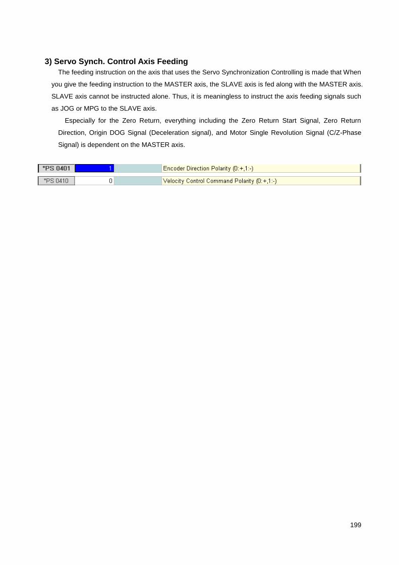
199
3) Servo Synch. Control Axis Feeding
The feeding instruction on the axis that uses the Servo Synchronization Controlling is made that When
you give the feeding instruction to the MASTER axis, the SLAVE axis is fed along with the MASTER axis.
SLAVE axis cannot be instructed alone. Thus, it is meaningless to instruct the axis feeding signals such
as JOG or MPG to the SLAVE axis.
Especially for the Zero Return, everything including the Zero Return Start Signal, Zero Return
Direction, Origin DOG Signal (Deceleration signal), and Motor Single Revolution Signal (C/Z-Phase
Signal) is dependent on the MASTER axis.

200
4.4.31 MULTI–Z / Spindle Axis Function 1) MULTI–Z Axis Function
This function selects one of more than two Z axis as the MAIN Z axis from the machine that has more
than two Z axis. When using this function, the program instruction can only be given to the MAIN Z axis
in AUTO Mode operation and in Manual operation, all Z axis can be fed regardless of the MAIN Z axis
status.
1.1) MULTI–Z Axis Control Parameter
To use MULTI-Z axis, all Z axis should be set as Z axis in „System Parameter‟. If Z axis is the
simultaneous control axis, {Simultaneous Control Axis Selection} parameter should be set. And then, set
the initial Main Z axis number during booting to {MAIN Z Axis Setting} parameter.
CNC Control Axis Setting [PP73 ~ 104]
Simultaneous Control Axis Selection [PP106 ~ 137]
MAIN Z Axis Setting [PP143]
1.2) MULTI–Z Axis Control Signal
Signal Type Signal Name
MAIN Z Axis Selection Signal ZNO [G53.00~G53.05]
MAIN Z Axis Status Signal ZNOL [F34.00~F34.05]
1.2.1) MAIN Z Axis Selection Signal ZNO [G53.00~G53.05]
[Function] MAIN Z Axis Selection Signal
[Action] 1. Enter the axis number to select as the MAIN Z axis in decimal unit to CNC.
[Ex] When selecting #3 axis as the MAIN Z axis, set G53.1 and G53.0 to HIGH.
2. When changing the MAIN Z axis, you should check if Z axis switching is completed
in CNC using MZNO signal.

201
1.2.2) MAIN Z Axis Status Signal ZNOL [F34.00~F34.05]
[Function] MAIN Z Axis Status Signal
[Action] Notifies PLC of the number of the currently selected MAIN Z axis in decimal number.
2) MULTI–Spindle Axis Control Function
This function selects one spindle as the main spindle axis from the machine that has more than
two spindle axis and rotates it. With this function, multiple spindles can be controlled sequentially and
rotated at the same time. In this case, all PLC initiated spindle control signals and S CODE, M03, M04,
M05 instruction and the spindle status signal output of CNC are only related to the control of the main
spindle.
2.1) MULTI–Spindle Axis Control Parameter
To use MULTI Spindle axis, all spindle axis should be set as the spindle axis in „System Parameter‟.
And then, set the initial main spindle axis number during booting to „System Parameter‟.
CNC Control Axis Setting [PP73 ~ 104]
MAIN Spindle Axis Setting [PP140]
2.2) MULTI–Spindle Axis Control Signal
Signal Type Signal Name
MAIN Spindle Axis Selection Signal SPNO [G52.00~G52.05]
MAIN Spindle Axis Status Signal SPNOL [F33.00~F33.05]

202
2.2.1) MAIN Spindle Axis Selection Signal SPNO [G52.00~G52.05]
[Function] MAIN Spindle Axis Selection Signal
[Action] 1. Enter the number of the spindle axis to select as the main spindle axis to CNC in decimal
unit.
[Ex] When selecting #5 axis as the main spindle axis, set G52.02 and G52.00 to HIGH.
2. When switching the main spindle axis, you must check if the spindle switching is
completed in CNC using SPNOLsignal.
2.2.2) MAIN Spindle Axis Status Signal SPNOL [F33.00~F33.05]
[Function] MAIN Spindle Axis Status Signal
[Action] Notifies PLC of the number of the currently selected main spindle axis in decimal number.
2.3) MULTI–Spindle Axis RPM Instruction Method
2.3.1) Speed Instruction Mode
N1 M~~ ………………….. 1.
N2 S1000 M03 ………….. 2.
N3 M++ ………………….. 3.
N4 S2000 M04 ………….. 4.
( M~~ : M Code that selects #5 axis as the main spindle)
( M++ : M Code that selects #6 axis as the main spindle)
1. When M~~ code is instructed, PLC inputs 5 to SPNO[G52] and checks if the spindle is selected
using SPNOL[F33] signal.
2. When S1000 M03 is instructed, PLC inputs the spindle control signal to CNC and checks the
Spindle Agree signal.
3. When M++ code is instructed, PLC selects #6 axis as the main spindle using the method
explained in the above step #1. However, in order to rotate #5 spindle axis at the same time as
#6 spindle axis, the drive contact status related to #5 spindle axis must be maintained.
4. When S2000 M04 is instructed, PLC performs the same operation as explained in the above
step #2.
5. Upon completion of the above procedures, #5 spindle axis rotates in the speed of
1000RPM(forward rotation), and #6 axis rotates in the speed of 2000RPM(reverse rotation).
6. The spindle override is applied only to the currently selected main spindle and when an arbitrary
spindle is switched from the main spindle to the sub spindle, the previous spindle override is
maintained.
2.3.2) Position Instruction Mode
Only the main spindle can be controlled by the position instruction mode. In addition, the CNC

203
Spindle Orientation is only supported by the main spindle.

204
4.4.32 PLC Axis Control Function 1) PLC Control Axis
PLC control axis represents the axis that can be fed by the PLC instruction and the axis feed
instruction cannot be made using G Code in the program. To use an axis as the PLC control axis,
„System Parameter‟ must be set. PLC control axis functions are categorized into position type, index
type (turret, magazine, index axis and so on), and speed type (conveyor, PLC control spindle and so on)
can be selected depending on the need. PLC control axis can receive the instruction regardless of the
operation mode and the manual feeding (JOG, MPG, STEP, and ZRN) can be used. However, be
careful not to have both the feeding instruction by the PLC axis control signal and the manual feeding
instructions entered to NC at the same time.
2) PLC Axis Control Signal Signal Type Signal Name
Feeding Start Signal PX_ST [G120.00~G120.1F]
Cancel Instruction Signal PX_CAN [G121.00~G121.1F]
Feeding Speed Selection Signal PX_MF [G123.00~G123.1F]
Override Selection Signal PX_MO [G124.00~G124.1F]
INPOSITION CHECK SKIP Signal PX_INPS [G125.00~G125.1F]
Feed Amount Instruction Signal PX_BLK [G131, G131, ~ … G193]
Feeding Speed Instruction Signal PX_FO [G132, G134, ~ … G194]
Feeding Done Signal PX_FIN [F110.00~ F110.1F]
Feeding Error Signal PX_NAK [F111.00~ F111.1F]
Current Feed Amount State Signal PX_POS [F121, F123 ~ … F183]
2.1) Feeding Start Signal PX_ST [G120.00~G120.1F]
[Function] Axis Feeding Start Signal
[Action] 1. When PX_ST switches from LOW→HIGH, the axis is fed to the PX_BLK instructed
position.
2. For index type, the axis is moved by the shortest path.
3. When the breaking is required such as the turret, change the Servo OFF signal to LOW
before this signal is generated and perform the BRAKE OFF operation.
4. It is maintained to HIGH until the Feeding Done Signal PX_FIN becomes HIGH.
5. The PLC Axis feeding number signal can be made as G120.00~G120.1F for #1 ~
#32axis.

205
2.2) Cancel Instruction Signal PX_CAN [G121.00~G121.1F]
[Function] Cancel instruction signal
[Action] When PX_CAN signal is instructed in the Position Type and Index Type PLC Axis Control,
all instructions are cancelled and PX_NAK signal is switched to HIGH.(Same operation
as RESET)
2.3) Feed Speed Selection Signal PX_MF [G123.00~G123.1F]
Override Selection Signal PX_MO [G123.00~G123.1F]
[Function] Feeding Speed / Override Selection Signal
[Action]
PX_MF signal is HIGH
When PX_MF is LOW in the position type and index type PLC axis, it is fed in the Rapid
Feeding Speed and the Rapid Feeding OVERRIDE is cancelled. In contrast, if PX_MF is
HIGH, it is fed in the speed of PX_FO.
PX_MO Signal is HIGH
For the position type and index type PLC axis, the feeding speed is determined by the
Rapid Feeding Speed * PX_FO(%) * 0.01 and for the speed type, the rotation speed
becomes PX_BLK * PX_FO(%) * 0.01. The input range of PX_FO is 0~250%.
[CAUTION] Only one of PX_MF and PX_MO should be HIGH.
2.4) INPOSITION CHECK SKIP Signal PX_INPS [G125.00~G125.1F]
[Function] INPOSITION CHECK SKIP Signal
[Action] When PX_ST and PX_INPS signal are set to HIGH simultaneously on the index type PLC axis,
PX_FIN signal is given out without INPOSITION CHECK after the axis feeding. This
function is used to prevent the single rotation that occurs as PX_FIN is outputted after the
complete stop of the axis whenever each instruction is ended if the continuous rotation
instruction is given to the index type PLC axis.
[CAUTION] When using PX_INPS signal, BRAKE or SHIFT FIN operation should be performed after
checking if INPOSITION DONE signal, INP [F87.0~F87.1F], is HIGH.
Axis Feeding
PX_ST
PX_FIN
PX_INPS

206
2.5) Feed Amount Instruction Signal PX_BLK [G131 ~ G193]
[Function] Axis Feed Amount Signal
[Action] Inputs the axis feed amount as an absolute instruction value. The range of the instruction
value will be ±232-1
– 1.
Control unit is based on the standard control unit setting value of PLC axis in „System
Parameter‟.
Index Type : Input index number (index count = parameter setting value )
Position Type : Input ± position/angle (Actual length = Input value * parameter control
unit )
Speed Type : Input ±RPM
PX_BLK1 [G131], PX_BLK2 [G133], ….
PX_BLK32 [G193] (PX_BLK(n) [G131 +2(n-1)])
2.6) Feeding Done Signal PX_FIN [F110.00~F110.1F]
[Function] Axis Feeding Done Signal
[Action] 1. Speed Reached Signal in case of Speed Type
2. When the Braking operation is required such as Turret, Servo OFF signal should be set
to HIGH after checking this signal and performing BRAKE ON operation. (Be careful
since the axis position may not be coincided if the timing differs for BRAKE ON and
Servo OFF operation.)
3. If the axis feeding is stopped by the external condition such as RESET during the axis
feeding, PX_NAK signal is changed to HIGH at the same time PX_FIN signal becomes
HIGH.
4. When PX_ST signal becomes LOW after completing the feeding, PX_FIN signal is also
changed to LOW.
2.7) Feeding Error Signal PX_NAK [F111.00~F111.1F]
[Function] Outputs whether the error occurs by the external conditions such as RESET or PX_CAN signal
during the axis feeding.
[Action] Once an error is occurred, it is maintained to HIGH until the normal axis feeding is resumed with
new feeding start signal PX_ST is given. (It is maintained even in case of RESET)

207
2.8) Current Feed Amount Status Signal PX_POS [F121 ~ F183]
[Function] Outputs the axis feeding position to PLC.
[Action] Current RPM is outputted in case of the Speed Type
PX_POS1 [G131], PX_POS2 [G133], …. PX_POS32 [G193] (PX_POS(n) [G131 +2(n-1)])
PLC Axis Control TIME CHART
PX_BLK [G]
PX_ST [G]
PX_FIN [F]
PX_POS [F]
Axis Feeding (CNC)
PX_BLK [G]

208
4.4.33 TWIN TABLE Control Function 1) TWIN TABLE Control
This function controls the table to move simultaneously or individually for the machine that involves
more than two tables. For this function, the master axis number should be entered to the slave axis of
the TWIN TABLE „System Parameter‟. This TWIN TABLE control supports the normal, individual and
Synchronous Operations are supported.
2) TWIN TABLE Control Signal TWNCTRL[G103.00~G103.1F]
[Function] TWIN TABLE Control Signal
[Action] Select from the normal, individual or Synchronous Operation through the combination of
signals.
Operation TWNCTRL-MASTER
TWNCTRL-SLAVE
Normal Operation LOW LOW
Individual Operation
MASTER Alone LOW LOW
SLAVE Alone LOW HIGH
Synchronous Operation HIGH HIGH
X
Z
Y V

209
3) Normal Operation
[Condition] When an M Code for normal operation is instructed, Set all the TWNCTRL [G103] bits
corresponding to the MASTER Axis number and SLAVE Axis number to LOW in PLC.
[Action] MASTER Axis is fed by the axis name set as MASTER in NC program as well as the axis
name set as SLAVE. For normal operation, it is the same as when TWIN TABLE Control
is not used and MASTER and SLAVE axis can engage in individual or simultaneous
feeding.
4) Individual (Single) Operation
Individual operation is used when the machining is performed on a single TABLE for a small amount
of work.
When the feeding instruction is given in form of the MASTER axis name in the program, MASTER or
SLAVE axis can be fed individually.
4.1) SLAVE Only Operation
[Condition] When M Code for SLAVE Only operation is instructed, TWNCTRL [G103] bits
corresponding to the MASTER axis number and SLAVE axis number are set to LOW
and HIGH in PLC, respectively.
[Action] When the instruction is made in terms of the axis name set as MASTER in the program, only the
SALVE axis is fed, but not the MASTER axis.
4.2) MASTER Only Operation
[Condition] Conditions for the MASTER Only operation are the same as normal operation.
[Action] MASTER Only operation engages in the same operation as normal operation.
Master Axis Instruction Master Axis Feeding
Slave Axis Instruction Slave Axis Feeding
Master Axis Instruction Slave Axis Feeding
Master Axis Instruction Master Axis Feeding
Slave Axis Instruction Slave Axis Feeding

210
5) Synchronous Operation
Synchronous Operation is used only when the machining is performed on TWO tables.
Synchronous operation gives the simultaneous instruction to the servomotors corresponding to
MASTER and SLAVE axis by the MASTER axis feeding instruction. After all, no alarm is generated for
the synchronization compensation and difference upon the position difference.
[Condition] When M Code for Synchronous operation is instructed, all TWNCTRL [G103] bits
corresponding to the MASTER axis number and SLAVE axis number are set to HIGH in
PLC.
[Action] When the instruction is made in terms of the axis name set as MASTER in the program, both the
MASTER and SALVE axis are simultaneously fed.
6) Manual Zero Return during TWIN TABLE Controlling
For the axis that uses the TWIN TABLE Control, Zero Return Start Signal follows the above
operation method, but, the Origin DOG signal and C-Phase signal are detected for individual axis.
Master Axis Instruction Master Axis Feeding
Slave Axis Feeding

211
4.4.34 CHOPPING Function
Signal Type Signal Name
CHOPPING Start Signal CHPST[G90.00]
CHOPPING Pause Signal CHPSP[G90.01]
CHOPPING Override Signal CHPOVR[G90.08~G90.0B]
CHOPPING in Progress Signal CHPL[F75.00]
1) CHOPPING Start Signal CHPST[G90.00]
[Function] CHOPPING Start Signal
[Action] When CHPST becomes HIGH, repetitive operation is engaged from Bottom Dead Center Top
Dead Center Bottom Dead Center after the Rapid Feeding to R point set in the
Parameter. And when CHPST becomes LOW, the chopping mode is completed after
feeding from Bottom Dead Center R point.
2) CHOPPING Pause Signal CHPSP[G90.01]
[Function] CHOPPING Pause Signal
[Action] When CHPST becomes HIGH during chopping, the chopping is paused temporarily after feeding
to R point. Chopping is resumed when CHPSP becomes LOW.

212
4.4.35 Z GAP TRACE Function 1) Z GAP TRACE
Z GAP TRACE Control function controls the distance between the nozzle (or tool) and the machining
object by adding a distance measuring device to Z axis, so that it is consistently maintained. It helps to
improve the problem of the steel plate laser cutter that the focus of the laser is dispersed as the distance
between the nozzle and the object varies. Z GAP TRACE function can be applied to up to 4 axes. It can
be applied to not just Z axis, but also all straight axis except the spindle.
2) Z GAP TRACE Control Signal
Signal Type Signal Name
Z Gap Trace Start Signal ZGTRC [G200.00~G200.03] Out of Z GAP Trace Sensor Measurement Range
Signal ZGFAR [G200.08~G200.0B]
Z Gap Trace In Progress Signal ZGTRCL [F200.00~F200.03]
When ZGTRC signal becomes HIGH, the axis is fed to the position where ZGFAR signal becomes
LOW in the speed specified by the parameter and Z Gap Trace is started. In this case, ZGTRCL signal
is changed to HIGH to notify PLC that Z Gap Trace is in progress. Alternately, Z Gap Trace can be
started after feeding the axis to the specified machine position by the parameter without using ZGFAR
signal.
Z GAP TRACE TIME CHART
Nozzle
Distance Measuring Device
Z Axis
Target Object
ZGTRC [G]
Z Gap Trace ON
ZGTRCL [F]
Feeding to Sensor Position
ZGFAR [G]
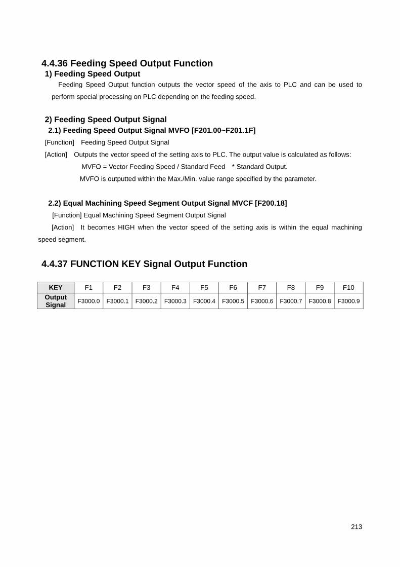
213
4.4.36 Feeding Speed Output Function 1) Feeding Speed Output
Feeding Speed Output function outputs the vector speed of the axis to PLC and can be used to
perform special processing on PLC depending on the feeding speed.
2) Feeding Speed Output Signal
2.1) Feeding Speed Output Signal MVFO [F201.00~F201.1F]
[Function] Feeding Speed Output Signal
[Action] Outputs the vector speed of the setting axis to PLC. The output value is calculated as follows:
MVFO = Vector Feeding Speed / Standard Feed * Standard Output.
MVFO is outputted within the Max./Min. value range specified by the parameter.
2.2) Equal Machining Speed Segment Output Signal MVCF [F200.18]
[Function] Equal Machining Speed Segment Output Signal
[Action] It becomes HIGH when the vector speed of the setting axis is within the equal machining
speed segment.
4.4.37 FUNCTION KEY Signal Output Function
KEY F1 F2 F3 F4 F5 F6 F7 F8 F9 F10
Output Signal
F3000.0 F3000.1 F3000.2 F3000.3 F3000.4 F3000.5 F3000.6 F3000.7 F3000.8 F3000.9

214
4.4.38 Screen Switching Function Screen Switching function is used to forcedly change the PLC screen.
1) Screen Switching Function Control Signal
Signal Type Signal Name
Screen Switching Number SCR0~SCR7 [G3004.00~G3004.07]
Screen Switching Start Number STRANS [G3005.00]
Screen Switching Done Signal SCFIN [F3005.00]
Current Screen Number SCRL0~SCRL7 [F3004.00~F3004.07]
Screen Switching TIME CHART
SCR [G]
STRANS [G]
SCFIN [F]
Screen Switch

215
4.4.39 PUNCH PRESS Control Function 1) Punch Press Control Related Signal
Signal Type Signal Name
Press Operation Start Signal PPF[F202.00]
Continuous Press Operation Signal NPF[F202.01]
Press Operation Skip Signal PPFS[G201.08]
Press Operation Standby Signal PPFW[G201.09]
Manual Press Mode Selection Signal PPMM[G201.0E]
Manual Press Operation Start Signal PPMF[G201.0F]
Multiple Machining Selection Signal PPMP1,PPMP2[G201.10~G201.11] Tool Change Position Selection Signal PPMTC[G201.13]
Press Operation Stop Signal PPE[G201.18]
Press Operation Done Signal PPFIN[G201.19]
Continuous Press Operation Done Signal NPFIN[G201.1A]
2) Press Mode Operation
Upon completion of axis feeding, CNC gives out PPF(Press Operation Start Signal) ad PLC starts the
Press Operation using this signal. When PPE(Press Operation Stop Signal) becomes HIGH, PSF
becomes LOW and PLC stops the Press Operation. Also, when PPFIN becomes HIGH, the next block is
processed. OPSDT2 is the time delay setting value for PPF becoming LOW. Depending on the OPSDT1
setting, PPF signal can be outputted before the axis feeding is completed.
Axis Feeding
PPF
PPE
PPFIN
OPSDT2 OPSDT1

216
3) Continuous Press Mode (Nibling Mode) Operation
In continuous press operation, PPF and NPF signals are changed to HIGH simultaneously after the
time delay of OPSDT4 at the initial position determination. PLC starts the press machine using this
signal and CNC processes the next block from when NSFIN becomes HIGH. When PPE becomes HIGH
at the last block, PPF becomes LOW (Same for NSF). PLC stops the Press Operation using this signal.
The block length for the continuous press operation is limited by the allowable position determination
time Ts(=Tt-Tp) (Tt refers to the time required for one press operation, Tp refers to the punching time)
and the maximum allowable block length is set to the parameter (if the setting value is exceeded, an
alarm is generated). Through OPSDT5 setting value, the time delay for the next block processing can be
defined and the moment when PPF becomes LOW can be delayed by OPSDT6.
4) Press Operation SKIP Function When PPFS signal becomes HIGH, PPF is not outputted after the axis feeding (without the Press
Operation) and the next block is processed after the delay of OPSDT3. Particularly when PPFS signal
becomes HIGH during Continuous Press Mode operation, PPF and NPF signal are changed to LOW by
PPE signal and the press operation is also skipped. In contrast, if PPFS signal becomes LOW during
Continuous Press Mode operation, the current block is taken and processed as the initial position
determining block of the continuous press operation.
Axis Feeding
이송 PPF
PPE
OPSDT4
NPF
NPFIN
Tt
Tp Ts
Initial Position Determination
OPSDT5
OPSDT6
Final Position Determination
Axis Feeding
이송 PSSKIP(PFL)
PSE(PE) OPSDT2

217
5) Press Operation Standby Function
If PPFW signal is HIGH, CNC waits to give out PPF signal until PPFW signal becomes LOW after the
axis feeding is completed.
6) Manual Press Function
1) Manual Press Mode Selection Signal PPMM
When PPMM signal is LOW, it is in Press Mode and when HIGH, it is in the Continuous Press
Mode.
2) Manual Press Operation Start Signal PPMF
This function performs the punching using the external control switch, not by program. When
PPMF signal is given, the output operation of PPF varies depending on PPMM signal.
While PPMM is LOW (Press Mode), if PPMF is HIGH, PPF is given out and if PPE is
HIGH,PPF becomes LOW after the delay of OPSDT2 time.
While PPMM is HIGH (Continuous Press Mode), if PPMF is HIGH, PPF is given out and if
PPMF is LOW, PPF also becomes LOW. However, if PPF and STL are HIGH, and PPFS is also
HIGH (PPFW signal is invalidated), PPMF signal is ignored.
7) Multiple Machining
The Multiple Machining Mode is determined as follows:
PPMP1 PPMP2 Mode
0 0 MULTI 3
1 0 MULTI 1
0 1 MULTI 2
8) Tool Change Position Selection Function
When T code is instructed while PPMTC is HIGH in MDI mode, T code is changed to move the
specified station to the tool change position and sent to PLC.

218
5 Parameter
5.1 Parameter Setup
[Notice] Please make sure that motor or hydraulic equipment won‟t be operated before the parameter is properly set for safety.
There are two kinds of parameter setup; setup in HX system and setup in parameter editor.
Once it‟s set, the parameter is saved as a file (.h2p). In case it‟s set by the parameter editor, it should be
copied to \system directory. The parameter setup page is as follows:
Program User Machining #1 Machining #2 System Macro Axis I/O Setup Special Function HMI
No. Value Unit Comment
General Setup
(개 생략) Number of Target Machining Units
(개 생략) Number of Machining Units
How to Apply Cutter Compensation Value (0: Diameter, 1: Radius)
X-axis Commend Method (0: Diameter, 1: Radius)
Decimal Point Check (0: Yes, 1: No)
90° Chamfering (0: I,J,K Command, 1: C Command)
How to Pause (0: Time, 1: Revolution)
Cutter Compensation Type (0: Indirectly, 1: Directly)
Internal Arc Cutting Speed Minimum Rate
Block Selection at Reset (0: Maintain, 1: Startup Block, 2: Call Block)
Statement No. Search (0: Yes, 1: No)
Radius Permissible Errors

219
Minimum Command Unit (Basic: 0.001), Will be Applied at the Inspection of
Decimal
Cylindrical Interpolation Rotation Axis (0: X, 1:Y, 2: Z)
If Modular Coordinate is Applied under Rotation Axis (0: No, 1: Yes)
X Axis
Y Axis
Axis No.
Axis Level
Control Method
Type of Axis Type of Equipment
1 X X, Y, Z
At the Same Time
Linear Axis
Gear Ratio 1:1, Ball Screw Pitch : 10
2 Y Linear Axis Gear Ratio 1:1, Ball Screw Pitch : 10
3 Z Linear Axis Gear Ratio 1:1, Ball Screw Pitch : 10
4 Turret PLC Control
Axis Rotation Axis Gear Ratio 1:10, Number of Cutters: 8
5 Spindle Ordinary Spindle
Gear Ratio 2:1, External Encoder, No Gear Shifting
For the parameter setup of the machine above, please select axis parameter first and then set [PS1
Axis Type Setup] parameter as shown below. Once it‟s set, reboot the system. Then, a parameter
setup page is displayed.
1) X-axis Selection
Program User Machining #1 Machining #2 System Macro Axis I/O Setup Special Function HMI
Axis #1
No. Value Unit Comment
Servo & Spindle Common Parameter
Set Type of Axis (0: Unused, 1: Servo, 2: Spindle)
Set Axis Port No.
Interface Method between CNC and Drive (0: SERCOS, 1: Analog)
2) Y-axis Selection

220
Program User Machining #1 Machining #2 System Macro Axis I/O Setup Special Function HMI
Axis #2
No. Value Unit Comment
Servo & Spindle Common Parameter
Set Type of Axis (0: Unused, 1: Servo, 2: Spindle)
Set Axis Port No.
Interface Method between CNC and Drive (0: SERCOS, 1: Analog)
3) Z-axis Selection
Program User Machining #1 Machining #2 System Macro Axis I/O Setup Special Function HMI
Axis #3
No. Value Unit Comment
Servo & Spindle Common Parameter
Set Type of Axis (0: Unused, 1: Servo, 2: Spindle)
Set Axis Port No.
Interface Method between CNC and Drive (0: SERCOS, 1: Analog)
4) Turret-axis Selection
Program User Machining #1 Machining #2 System Macro Axis I/O Setup Special Function HMI
Axis #4
No. Value Unit Comment
Servo & Spindle Common Parameter
Set Type of Axis (0: Unused, 1: Servo, 2: Spindle)
Set Axis Port No.
Interface Method between CNC and Drive (0: SERCOS, 1: Analog)
5) Spindle-axis Selection

221
Program User Machining #1 Machining #2 System Macro Axis I/O Setup Special Function HMI
Axis #5
No. Value Unit Comment
Servo & Spindle Common Parameter
Set Type of Axis (0: Unused, 1: Servo, 2: Spindle)
Set Axis Port No.
Interface Method between CNC and Drive (0: SERCOS, 1: Analog)
5.1.1 Axis Parameter Setup
[Notice] 1. If Gain is set too high [servo:PS306, PS312, spindle:PS174~, PS183~], motor congestion could occur. 2. If the speed command polar setup [servo:PS410, spindle:PS290] is not properly done, motor
congestion could occur.
1) Example of X, Y, Z-axis Setup

222
Servo & Spindle Common Parameter
Set Type of Axis (0: Unused, 1: Servo, 2: Spindle)
Set Axis Port No.
Interface Method between CNC and Drive (0: SERCOS, 1: Analog)
Servo Axis Setup
Set Type of Axis Feed (1: Linear (V), 2: Rotation (V), 3: Linear (P), 4: Rotation (P))
If Drive Return-to-Origin is Used (0: No, 1: Yes)
Set Synchronous Control Master-axis No.
Backlash Rate
Friction Compensation Value
Pitch Error Compensation Null Setup (0: Compensated, 1: Non-compensated)
Pitch Error Input Interval
Pitch Error Table Index against Origin
Number of Teeth of Machine Gear
Number of Teeth of Motor Gear
Travel per Ball Screw Rotation
Encoder (0: Used, 1: Unused)
Encoder Type (0: Incremental, 1: Absolute)

223
Encoder Pulse Output (0: Linear, 1: Modular)
Encoder Resolution (Resolution after Subdivision)
Positional Servo Control Resolution
Open Loop Control (0: Close Loop, 1: Open Loop)
Position Control P Gain
Synchronous Error Compensation Gain of Synchronous Control
Feed Forward Gain
Tracking Error Allowable Range
Synchronous Error Allowable Range of Synchronous Control
Maximum Value of Speed Command
D/A Converter Resolution, Velocity Data Scale
Encoder C-phase Polarity
Encoder Direction
Servo Ready Polarity
Servo Alarm Polarity
Speed Command Polarity
Servo On Polarity
Servo Reset Polarity
If Encoder Phase Alarm is Detected
If Encoder C-phase Alarm is Detected
The figure above shows how to set X axis to Axis #1 range. Y axis and Z axis can also be set to Axis #2
and Axis #3 respectively by the same method. The difference is that if Y axis and Z axis use Port #2 and
Port #3 respectively for [PS2 Axis Port No.] setup, they should be set to #2 and #3 accordingly. Besides,
Gain [PS306, PS312] and Polarity [PS400~415] parameter should be properly set based on the system
features.

224
2) Turret-axis Setup
Servo & Spindle Common Parameter
Set Type of Axis (0: Unused, 1: Servo, 2: Spindle)
Set Axis Port No.
Interface Method between CNC and Drive (0: SERCOS, 1: Analog)
Servo Axis Setup
Set Type of Axis Feed (1: Linear (V), 2: Rotation (V), 3: Linear (P), 4: Rotation (P))
If Drive Return-to-Origin is Used (0: No, 1: Yes)
Set Synchronous Control Master-axis No.
Backlash Rate
Friction Compensation Value
Pitch Error Compensation Null Setup (0: Compensated, 1: Non-compensated)
Pitch Error Input Interval
Pitch Error Table Index against Origin

225
Positional Servo Out-of-Step Compensation Function
Positional Servo Residual Pulse Compensation Function
Number of Teeth of Machine Gear
Number of Teeth of Motor Gear
Travel per Ball Screw Rotation
Encoder (0: Used, 1: Unused)
Encoder Type (0: Incremental, 1: Absolute)
Encoder Pulse Output (0: Linear, 1: Modular)
Encoder Resolution (Resolution after Subdivision)
Positional Servo Control Resolution
Open Loop Control (0: Close Loop, 1: Open Loop)
Position Control P Gain
Synchronous Error Compensation Gain of Synchronous Control
Feed Forward Gain
Tracking Error Allowable Range
Synchronous Error Allowable Range of Synchronous Control
Maximum Value of Speed Command
D/A Converter Resolution, Velocity Data Scale
Encoder C-phase Polarity
Encoder Direction
Servo Ready Polarity
Servo Alarm Polarity
Speed Command Polarity
Servo On Polarity
Servo Reset Polarity
If Encoder Phase Alarm is Detected
If Encoder C-phase Alarm is Detected
The figure above shows how to set Turret axis to Axis #4 range. Gain [PS306, PS312] and Polarity
[PS400~415] parameter should be properly set based on the system features.

226
3) Spindle-axis Setup
Servo & Spindle Common Parameter
Set Type of Axis (0: Unused, 1: Servo, 2: Spindle)
Set Axis Port No.
Interface Method between CNC and Drive (0: SERCOS, 1: Analog)
Servo Axis Setup
Type of Motor / Drive (1: General Spindle, 2: Digital, 3: Servo Motor)
Backlash Rate in Each Gear Shift (#1)
Backlash Rate in Each Gear Shift (#2)
Number of Shifting Gear
Number of Teeth of Spindle Motor in Each Gear Shift (#1)
Number of Teeth of Spindle Motor in Each Gear Shift (#2)
Number of Teeth of Spindle Machine in Each Gear Shift (#1)
Number of Teeth of Spindle Machine in Each Gear Shift (#2)

227
Spindle Revolution (10V) in Each Gear Shift (#1)
Spindle Revolution (10V) in Each Gear Shift (#2)
Maximum Spindle Revolution in Each Gear Shift (#1)
Maximum Spindle Revolution in Each Gear Shift (#2)
Spindle Revolution at Gear Shifting
Encoder Connection Method (0: None, 1: Direction Connection with Spindle Motor, 2:
External)
Encoder Pulse Output (0: Linear, 1: Modular)
Encoder Resolution (Resolution after Subdivision)
Spindle Rotation Speed Agree Range
Spindle Rotation Speed Zero Speed Agree Range
Spindle Orientation Speed
Spindle Orientation Direction (0:+, 1:-)
Spindle Orientation Offset
Position Mode P Gain in Each Gear Shift (#1)
Position Mode P gain in Each Gear Shift (#2)
Position Mode Feed Forward Gain in Each Gear Shift (#1)
Position Mode Feed Forward Gain in Each Gear Shift (#2)
Tracking Error Allowable Range
Maximum Value of Speed Command
Encoder C-phase Polarity
Encoder Direction
Servo Ready Polarity
Servo Alarm Polarity
Speed Command Polarity
Servo On Polarity
Servo Reset Polarity
If Encoder Phase Alarm is Detected (0: Yes, 1: No)
If Encoder C-phase Alarm is Detected (0: Yes, 1: No)
The figure above shows how to set Spindle axis to Axis #5 range. Gain [PS174~, PS183~] and Polarity
[PS280~295] parameter should be properly set based on the system features.

228
5.1.2 System Parameter Setup
Even though each axis (X, Y, Z, Turret, or Spindle) is set to Axis (1 – 5) range, CNC still doesn‟t
recognize each axis as X, Y, Z, Turret, or Spindle. Instead, it recognizes each axis as Axis 1, Axis 2,
Axis 3, Axis 4, and Axis 5. Therefore, the process that each axis is recognized as X, Y, Z, Turret, and
Spindle in system parameter range is necessary. The setup process is shown below. Besides, X, Y, and
Z axes are needed to be set as synchronous control axes. In case of turret axis, above all, it needs to be
set to index type PCL control axis and the basic control unit of PLC control axis to 8. Besides, a proper
value should be entered to H/W and S/W setup part based on the system features.
H/W Setup
Select Key Panel

229
RS232C Key-used COM Port No. (0: Unused, 1: COM1, 2:COM2)
NC CARD TYPE
If SRAM is used (0: No, 1: Yes)
In case SRAM is not used, Interval of Storage in File System
S/W Setup
Maximum Number of Event Log Registration Files
Event Log File No. in Registration
System Sampling Time
Position Control Sampling Time
Backward Buffer Size
Axis Setup
CNC-axis Setup (Axis 1)
CNC-axis Setup (Axis 2)
CNC-axis Setup (Axis 3)
CNC-axis Setup (Axis 4)
CNC-axis Setup (Axis 5)
Select Synchronous Control Axis (Interpolation Axis) (0: Asynchronous, 1: Synchronous) (Axis 1)
Select Synchronous Control Axis (Interpolation Axis) (0: Asynchronous, 1: Synchronous) (Axis 2)
Select Synchronous Control Axis (Interpolation Axis) (0: Asynchronous, 1: Synchronous) (Axis 3)
Select Synchronous Control Axis (Interpolation Axis) (0: Asynchronous, 1: Synchronous) (Axis 4)
Select Synchronous Control Axis (Interpolation Axis) (0: Asynchronous, 1: Synchronous) (Axis 5)
Main Spindle No.
Main Z-axis No.
Set Master-axis No. of Slave-axis in Twin Table Control (Axis 1)
Set Master-axis No. of Slave-axis in Twin Table Control (Axis 2)
Set Master-axis No. of Slave-axis in Twin Table Control (Axis 3)
Set Master-axis No. of Slave-axis in Twin Table Control (Axis 4)
Set Master-axis No. of Slave-axis in Twin Table Control (Axis 5)
Select PLC Axis (0: Unused, 1: Index Type, 2: Positional, 3: Speed Type) (Axis 1)
Select PLC Axis (0: Unused, 1: Index Type, 2: Positional, 3: Speed Type) (Axis 2)
Select PLC Axis (0: Unused, 1: Index Type, 2: Positional, 3: Speed Type) (Axis 3)
Select PLC Axis (0: Unused, 1: Index Type, 2: Positional, 3: Speed Type) (Axis 4)
Select PLC Axis (0: Unused, 1: Index Type, 2: Positional, 3: Speed Type) (Axis 5)
Basic Control Unit in PLC Axis (Axis 1)
Basic Control Unit in PLC Axis (Axis 2)
Basic Control Unit in PLC Axis (Axis 3)
Basic Control Unit in PLC Axis (Axis 4)
Basic Control Unit in PLC Axis (Axis 5)

230
5.1.3 Other Parameter Setup
Machining #1/ Machining #2 Parameter
Acceleration / Deceleration Time Constant, MANUAL Operation, AUTO Operation, and Machining
Performance parameters are set.
I/O Setup Parameter
SERCOS communication parameter and I/O Configuration parameter are set.
Program Parameter
Machining program, cycle program, and compensation-related parameters are set.
User Parameter
DNC and TPG-related parameters are set.
HMI Parameter
HMI page parameter is set.
* Relationship between Parameter and System Macro
Type of Parameter Option for System Macro Example
PA 1000 PA[1] = #1001
PI 3000 PI[200] = #3200
SV 4000 SV[11] = #4011
SN 6000 SN[100] = #6100
PU 9000 PU[11] = #9011
PM 20000 PM[1011] = #21011
PP - -
PS - -
For more parameter setup information, refer to the parameter description and H/W-related information.

231
5.2 Program Parameter
[Notice] _* -type parameter is a parameter which is applied during system reboot
5.2.1 General Setup
PA 1431 2431
Number of Target Machining Units
[Definition] R_NSPTN
[Interval] 0 / 99999
[Unit] Unit(s)
[Description] A parameter which makes the message pop up if the number of target units is achieved
The message pops up if the number of machining units exceeds the parameter setpoint
In case of „0,‟ the number of target units will not be examined
[Application] Common
SN 101 6101
Number of Machining Units
[Definition] R_CUTCNT
[Interval] 0
[Unit] Unit(s)
[Description] A parameter which shows the number of units machined
It automatically increases if M30 or M02 is met in the inside of CNC
In the setup, it can be entered as 0
It‟s used to make the message pop up with regard to the number of target machining
units parameter
[Application] Common
PI 72 3072
How to Apply Cutter Compensation Value
[Definition] R_RCOMP
[Interval] 0 / 1
[Description] 0: Diameter, 1: Radius
[Application] Common

232
PI 73 3073
X-axis Command Method
[Definition] R_XCMD
[Interval] 0 / 1
[Description] A parameter which informs if X-axis commanded in NC program is diameter or radius (not
related with screen display)
(0: Diameter, 1: Radius)
It‟s applied in lathe type only
[Application] Lathe
PI 76 3076
Decimal Point Check
[Definition] R_CHKDECPT
[Interval] 0 / 1
[Unit] -
[Description] 0: Checks Decimal Point (In there is a decimal, it‟s commanded by mm. If there isn‟t, it‟s
commanded by um)
1: Does not Check Decimal Point (by mm, always)
In case of „0,‟ the minimum command unit of PI[170] is applied
[Application] Common
PI 170 3170
Minimum Command Unit
[Definition] R_MIN_CMM
[Interval] 0 / 0.999
[Unit] mm
[Description] A parameter which sets the minimum unit by which the command value is applied in case
there is Decimal Point Check (PI 76)
For example, if „1‟ is commanded while the minimum command unit is 0.001, the
command value is 0.001mm; or
if „1‟ is commanded while the minimum command unit is 0.1, the command value is
0.1mm
[Application] Common

233
PI 82 3082
90° Chamfering
[Definition] R_CHFCMD
[Interval] 0 / 1
[Unit] -
[Description] A parameter which sets the chamfering method between the right-angled line and the line
block
0:I, J, K Command, 1:C Command (In case C-axis is not used)
[Application] Lathe
PI 120 3120
How to Pause
[Definition] R_DWELL
[Interval] 0 / 1
[Unit] -
[Description] A parameter which sets if the data which are commanded to X or P in G04 (Pause)
function are used as Time or Revolution
If this parameter is set to „1‟ under feed-per-revolution state, it‟s applied as Revolution. In
other cases, on the contrary, it‟s applied as Time.
(0: Time, 1: Revolution)
[Application] Common
PI 128 3128
Cutter Compensation Type
[Definition] R_COMPTYPE
[Interval] 0 / 1
[Unit] -
[Description] Feed type setting at the start and end part of cutting compensation
(0: Indirect Feed (Type 2), 1: Direct Feed (Type 1))
G42
Workpiece
Type 2
G42
Workpiece
Type 1

234
PI 172 3172
Cutter Interference Check during Cutter Compensation
[Definition] R_INTER_CHECK
[Interval] 0 / 1
[Description] A parameter which sets if the cutter interference will be checked or not during cutter
compensation
(0: No, 1: Yes)
“F_8220A Cutter Interference Occurred (Compensation is Too High)”
[Application] Common
PI 133 3133
Block Selection at Reset
[Definition] R_RST_SBLK
[Interval] 0 / 2
[Description] A parameter which sets if it should be initialized as the program startup block when
RESET is entered
(0: Maintain as current block, 1: Initialize as main program startup block, 2: Initialize as
the current block of main program)
In order to resume the program, it should be set to „0.‟
For CF> 0 Current Block Maintain status, „Maintain PI[177] Workpiece Coordinate System‟
parameter should be set to „Maintain‟ status.
[Application] Common
PI 134 3134
Statement No. Search
[Definition] R_SRCH_LABEL
[Interval] 0 / 1
[Description] The program statement number (N__) storage buffer is limited up to 1,000
This buffer is necessary in a program which changes the program sequence using GOTO
or others
In case there is N__ command in more than 1,000 blocks, an alarm goes off
A parameter which sets if the statement No. will be searched or not
A large CAM program often does not have GOTO with statement number and has more
than 1,000 statement numbers. Therefore, the parameter should be set to „1.‟
(0: Yes, 1:No)
[Application] Common

235
PI 151 3151
Radius Permissible Errors
[Definition] R_ARCTOL
[Interval] 0.001 / 3, 0.0001 / 0.1
[Unit] mm, inch
[Description] A parameter which sets the radius permissible errors at the start and end point when an
arc is commanded
If this value is high, the accuracy at the end of arc decreases
[Application] Common
PI 171 3171
Recreate Arc Center When An Arc Alarm Goes Off
[Definition] R_ARCCEN_GEN
[Interval] 0, 1
[Description] A parameter which sets if the arc center will be recreated with no arc alarm in case the
radius permissible error range is exceeded at the start and end pint when I, J, or K arc is
commanded
(0: Alarm goes off, 1: Recreate arc center)
[Application] Common
PI 155 3155
Cylindrical Interpolation Rotation Axis
[Definition] R_CYLROTAX
[Interval] 0 / 2
[Unit] -
[Description] An axis that maps rotation axis during circular interpolation in cylindrical interpolation
mode
The axes are X, Y, and Z. Having the rotation axis mapped in the axis selected, the
circular interpolation is executed
For example, if the rotation axis is mapped in X axis and it‟s XY plane (G17) status, the
horizontal line becomes rotation axis while the vertical line becomes Y axis. However, in
case the plane is ZX (G18), the horizontal line becomes Z axis while the vertical line
becomes rotation axis. If the plane is YZ (G19), on the contrary, the circular interpolation
can not be enabled with the rotation axis commanded (0:X, 1:Y, 2:Z)
[Application] Common

236
5.2.2 If Modular Coordinate is Applied Under Rotation Axis
(0: No 1:Yes)
PI 156 / 164 3156 / 3164
If Modular is Applied Under Rotation Axis (Unused)
[Definition] R_ROT_MOD
[Interval] 0 / 1
[Unit] -
[Description] Unused parameter
Uses modular coordinate display function setup (PP 447 ~ PP 478)
[Application] Turning Grinder and Turning Center
5.2.3 Non-Buffering M Code
PI 165 / 169 3165 / 3169
Non-Buffering M Code
[Definition] R_EOM_MCODE
[Interval] 0 / 9999
[Unit] -
[Description] A parameter which enters M code No. which does axis feed completion inspection
Once M code No. is commanded, the axis feed completion inspection is conducted after
M code execution
(It‟s used to update the position value after Z gap trace or manual intervention)
Default value is 0. In this case, it‟s ignored
[Application] Common

237
5.2.4 2, 3, 4 Origin Setup
PM 2097 / 2128 22097 / 22128
Origin 2 Position
[Definition] OZRN2POS
[Interval] -99999.9999/99999.9999
[Unit] mm, inch, deg
PM 2129 / 2160 22129 / 22160
Origin 3 Position
[Definition] OZRN3POS
[Interval] -99999.9999/99999.9999
[Unit] mm, inch, deg
PM 2161 / 2192 22161 / 22192
Origin 4 Position
[Definition] OZRN4POS
[Interval] -99999.9999/99999.9999
[Unit] mm, inch, deg

238
5.2.5 Default Setup
PI 144 3144
Default Setup Modal Feed
[Definition] R_DFT 1GRP
[Interval] 0 / 1
[Unit] -
[Description] A parameter which selects G code which will be applied to default modal when it‟s
transferred without G code command (G00, G01)
(0: Rapid Feed (G00), 1: Cutting Feed (G01))
[Application] Common
PI 145 3145
Default Setup Modal Plane
[Definition] R_DFTPLN
[Interval] 0 / 2
[Unit] -
[Description] A parameter which selects G code which will be applied to default modal when it‟s
transferred without G code command (G17, G18, G19)
(0: Rapid Feed (G00), 1: Cutting Feed (G01))
(0:XY(G17), 1:ZX(G18), 2:YZ(G19))
In case of lathe type, it should be set to „1.‟ It will be applied at reset
[Application] Common
PI 146 3146
Default Setup Modal Absolute / Incremental
[제 목] R_DFTAI
[Interval] 0 / 1
[Unit] -
[Description] A parameter which selects G code which will be applied to default modal when there is no
G code command (G90, G91)
(0: Absolute (G90), 1: Incremental (G91))
[Application] Common

239
PI 147 3147
Default Setup Modal Inch / Metric
[Definition] R_DFTINM
[Interval] 0 / 1
[Description] A parameter which selects G code which will be applied to default modal when there is no
G code command (G20, G21)
When G code is commanded, this parameter value changes
(0:Metric(G21), 1:Inch(G20))
[Application] Common
PI 148 3148
Default Setup Modal Forbidden Area Inspection
[Definition] R_DFTSTR
[Interval] 0 / 1
[Description] A parameter which selects G code which will be applied to default modal when there is no
G code command (G22, G23)
When G code is commanded, this parameter value changes
(0:Stroke on(G22), 1:Stroke off(G23))
[Application] Common
PI 150 3150
Default Setup Modal Coordinate System Rotation
[Definition] R_DFTROT
[Interval] 0 / 1
[Description] A parameter which selects G code which will be applied to default modal when there is no
G code command (G68, G69) in case of milling
(0: Cancel (G69), 1: Apply (G68))
[Application] Common
PI 117 3117
Coordinate System Rotation Angle
[Definition] R_ROTANG
[Interval] -999.999 / 999.999
[Unit] degree
[Description] A basic parameter which is used when there is no rotation angle command at the rotation
command in the coordinate system
[Application] Common

240
5.2.6 Cycle Setup
PI 51 3051
Rough Cycle Infeed (D)
[Definition] R_G71G72D
[Interval] 0 / 99.999, 0 / 9.9999
[Unit] mm, inch
[Description] A parameter which is used as default when G71 U_ or G72 U_ is not commanded
In case there is a command in NC program, the parameter value changes as well
[Application] Lathe
PI 52 3052
Rough Cycle Retreat Distance
[Definition] R_G71G72R
[Interval] 0 / 9.999, 0 / 0.9999
[Unit] mm, inch
[Description] A parameter which is used as default when G71 U_ or G72 U_ is not commanded
In case there is a command in NC program, the parameter value changes as well
Refer to <Figure> in PI51 above
[Application] Lathe
PI 53 3053
Imitation Cycle X Removal Rate (XR)
[Definition] R_G73XR
D
R

241
[Interval] -99.999 / 99.999, -9.9999 / 9.9999
[Unit] mm, inch
[Description] A parameter which is used as default when G73 U_ is not commanded
In case there is a command in NC program, the parameter value changes as well
[Application] Lathe
PI 54 3054
Imitation Cycle Z Removal Rate (ZR)
[Definition] R_G73ZR
[Interval] -99.999 / 99.999, -9.9999 / 9.9999
[Unit] mm, inch
[Description] A parameter which is used as default when G73 W_ is not commanded
In case there is a command in a program, the parameter value changes as well
Refer to Refer to <Figure> PI51 above
[Application] Lathe
XR
Z
R

242
PI 55 3055
Number of Imitation Cycle Repetition
[Definition] R_G73RPCNT
[Interval] 1 / 99
[Unit] -
[Description] A parameter which is used as default when G73 R_ is not commanded
In case there is a command in NC program, the parameter value changes as well
[Application] Lathe
PI 56 3056
Drill Cycle Retreat Distance
[Definition] R_HMDRRTR
[Interval] 0 / 99.999, 0 / 9.9999
[Unit] mm, inch
[Description] A parameter which is used as default when G74 R_ or G75 R_ is not commanded
In case there is a command in NC program, the parameter value changes as well
[Application] Lathe
PI 70 3070
Axis 1 Shift Direction of Fine Boring Cycle
[Definition] R_G76SFT1
[Interval] -1 / 1
[Description]
[Application] Milling
PI 71 3071
Axis 2 Shift Direction of Fine Boring Cycle
R
Shift Direction

243
[Definition] R_G76SFT2
[Interval] -1 / 1
[Description] Refer to <Figure> in PI 71 above
[Application] Milling
PI 129 3129
Peck Drill Cycle Allowance Rate
[Definition] R_PECK_TOL
[Interval] 0 / 99.999, 0 / 9.9999
[Unit] mm, inch
[Description] Allowance rate parameter during peck drill cycle or high-speed peck drill cycle
[Application] Common
d
Peck Drill Cycle
d
High-Speed Peck Drill Cycle

244
5.2.7 Scale Setup
PI 149 3149
Modal Scale in Scale Setup
[Definition] R_DFTSCALE
[Interval] 0 / 1
[Unit] -
[Description] A parameter which selects G code which will be applied to default modal when there is no
G code command (G50, G51) in case of milling
(0: Cancel (G50), 1: Apply (G51))
[Application] Common
PI 108 / 116 3108 / 3116
Scale Setup
[Definition] R_SCALE
[Interval] -9999 / 9999
[Description] A parameter which is applied to 9 axes (X,Y,Z,A,B,C,U,V,W) and used when there is no
scale command
In case of a negative number, the mirror image function is also enabled
[Application] Common

245
5.2.8 Single-direction Positioning Overrun Feed Rate
PI 61 / 69 3061 / 3069
Single-direction Positioning Overrun Feed Rate (O)
[Definition] R_SNGDIRPOS
[Interval] -99.999 / 99.999, -9.9999 / 9.9999
[Unit] mm, inch
[Description] Applied to 9 axes (X,Y,Z,A,B,C,U,V,W)
[Application] Milling
+ O
- O

246
5.2.9 Automatic Corner Override Setup (Related with Compensation)
PI 124 3124
Start Field of Automatic Corner Override Setup
[Definition] R_G62STR
[Interval] 0 / 999.999, 0 / 99.9999
[Unit] mm, inch
[Description] Sets the override range (Ls) of start block which forms a corner when an automatic corner
override is commanded
[Application] Milling
PI 125 3125
End Field of Automatic Corner Override Setup
[Definition] R_G62END
[Interval] 0 / 999.999, 0 / 99.9999
[Unit] mm, inch
[Description] Sets the override range (Le) of end block which forms a corner when an automatic corner
override is commanded
Refer to <Figure> in PI124
[Application] Milling
PI 126 3126
Automatic Corner Override Setup Magnifying Rate
[Definition] R_G62OVR
[Interval] 10 / 100
[Unit] %
[Description] A magnification which will be applied to feed speed during Automatic Corner Override
field
Automatic Corner Override Feed Speed = Current Command Feed Speed x Magnifying Rate x 0.01
[Application] Milling
Le
Ls
Feed

247
PI 130 3130
Automatic Corner Override Setup Slip Angle
[Definition] R_G62_ANG
[Interval] 2 / 178
[Unit] Degree
[Description] Enters the corner maximum angle which sets the automatic corner override application
block
In case 0-2 is entered, 178 is applied
[Application] Milling
PI 131 3131
Automatic Corner Override Setup Type
[Definition] R_G62_TYPE
[Interval] 0 / 1
[Unit] -
[Description] A parameter which is applied to reduce the cutter load during internal machining at the
compensation
In case Always Apply is set, however, the automatic corner override is applied based on
the corner angle in each block
(0: Applied in internal corner only at the compensation, 1: always applied)
[Application] Milling
PI 153 3153
Automatic Corner Override Speed
[Definition] R_AOVRFEED
[Interval] 0 / 99999.999, 0 / 9999.9999
[Unit] mm/min, in/min
[Description] A speed is directly entered in the automatic corner override deceleration interval
In case the value is „0,‟ PI[126] override is applied
If it‟s above 1, the speed in the corner deceleration interval is applied
In case the command speed is lower than the value above, it‟s transferred by the
command speed
[Application] Milling

248
PI 132 3132
Inner Arc Cutting Speed Minimum Rate
[Definition] R_MDR
[Interval] 0.01 / 1.00
[Unit] %
[Description] The inner arc cutting speed is determined by Rc/Rp*F during arc feed in the
compensation
In case Rc/Rp is less than the minimum deceleration rate, it‟s limited to the value which is
set in the minimum deceleration rate
Actual Feed = Minimum Deceleration Rate*F
[Application] Milling
Path Programmed
Cutter Centered
Path

249
5.2.10 Work-piece Coordinate System Setpoint in Each Axis
PI 174 3174
If Work-piece Coordinate System Setpoint in Each Axis is Used or Not
[Definition] R_PWORK_USE
[Interval] 0 / 1
[Unit] -
[Description] A parameter which sets if the work-piece coordinate system setpoint input parameter in
the axes (X,Y,Z,A,B,C,U,V,W) (PI[156~164]) is used or not
In case this parameter is „1‟ (Work-piece coordinate system setpoint is used)
[Application] Common
PI 156 / 164 3156 / 3164
Work-piece Coordinate Setpoint in an Origin
[Definition] R_PWORK_POS
[Interval] -99999.999 / 99999.999, -9999.9999 / 9999.9999
[Unit] mm, inch
[Description] A parameter which enters the work-piece coordinate system setpoint in the origin of the
axes (X,Y,Z,A,B,C,U,V,W) (PI[156~164]) is used
(Enter the coordinate value of current position in an origin)
At reset, it‟s set to the basic work-piece coordinate system when the work-piece
coordinate is cancelled (PI [77]) or not set (G50(92)X_ (Y_) Z_, T code) yet
In case the work-piece coordinate system is changed by commanding G50 X_ Z_, G92
X_ Z_, or G54 ~ G59, the coordinate system which is commanded in the program is valid
[Application] Common

250
5.2.11 Automatic Cutter Offset
PI 119 3119
Select Automatic Cutter Offset Setup Method
[Definition] R_GEOOFF_REL
[Interval] 0 / 1
[Description] A parameter which sets if the absolute position will be entered based on the coordinate
system when geometry offset value is entered using automatic cutter compensation
function (Tool Presetter) or if the relative position against each base will be entered as the
geometry offset value
(0: Based on the absolute coordinate, the geometry offset value is entered
1: The relative position against each automatic cutter base is entered as the geometry
offset value)
[Application] Common

251
PI 121 / 123 3121 / 3123
Distance (X, Y, and Z) between Center of Automatic Cutter Offset Device and Center of Reference in Automatic Coordinate System
[Definition] R_MEA_SHIFT_XYZP
[Interval] -99999.999 / 99999.999, -9999.9999 / 9999.9999
[Unit] mm, inch
[Description] Distance parameter between the center of automatic cutter offset device and the
reference of a certain automatic cutter compensation
(In case of X-axis of lathe, it should be entered in consideration of the distance with the
center of spindle)
+ X
(Origin)
+Z
CUTTER
Shift X Distance Shift Z Distance
Reference of A Certain Automatic Cutter Compensation
[Application] Lathe

252
PI 135 / 137 3135 / 3137
Automatic Cutter Offset‟s Positive Measurement Base Distance X, Y, Z
[Definition] R_MEA_REF_XYZP
[Interval] -99999.999 / 99999.999, -9999.9999 / 9999.9999
[Unit] mm, inch
[Description] Base distance parameter from the automatic cutter offset to X,Y, and Z‟s positive feed
direction contact point
+ X
(Origin)
+Z
Off X
-X +X CUTTER
-X Feed Direction Contact Point Xt Off Z
-Z Feed Direction Contact Point
-Z
Zt
+Z
[Application] Common
PI 138 / 140 3138 / 3140
Automatic Cutter Offset‟s Negative Measurement Base Distance X, Y, Z
[Definition] R_MEA_REF_XYZM
[Interval] -99999.999 / 99999.999, -9999.9999 / 9999.9999
[Unit] mm, inch
[Description] Base distance parameter from the automatic cutter offset to X,Y, and Z‟s negative feed
direction contact point
Refer to <Figure> in PI 135 / 137 above
[Application] Common

253
PI 141 3141
Automatic Cutter Offset‟s Deceleration Cutter Start Length
[Definition] R_ATDSL
[Interval] 0 / 99.999, 0 / 9.9999
[Unit] mm, inch
[Description] A parameter (r) of deceleration applied interval for the measurement of the automatic
cutter length
Rapid Fp Measurement Command Position
(a) (b) (c) (d)
Start Point Deceleration err err
r
[Application] Common
PI 142 3142
Automatic Cutter Measurement Detectable Interval in Automatic Cutter Offset
[Definition] R_ATMER
[Interval] 0 / 99.999, 0 / 9.9999
[Unit] mm, inch
[Description] Automatic cutter length measurement detectable interval parameter
Refer to <Figure> in PI 141 above
[Application] Common
PI 143 3143
Automatic Cutter Offset‟s Auto Cutter Deceleration
[Definition] R_ATDF
[Interval] 0.001 / 999.999, 0.0001 / 99.9999
[Unit] mm/min, inch/min
[Description] Automatic cutter length measurement deceleration parameter (Fp)
Refer to <Figure> in PI 141 above
[Application] Common

254
5.2.12 T-code Setup
PI 78 3078
Cutter Offset Application Method
[Definition] R_SELOFFMD
[Interval] 0 / 1
[Unit] -
[Description] 0: Geometry offset is conducted as SHIFT function
1: Geometry offset is conducted as cutter feed
Geometry offset is conducted as SHIFT function
(70,50) (70,100)->(70,90) After N5 block execution, the ф60 coordinate value has changed to (70,90) There is no axis feed
Geometry offset is conducted as
cutter feed
1 (70,100) (70,50) (70,100) 2
During N5 block execution, Transfer X axis by 5mm and Z axis by -10mm. The current position stay the same (70,100)
[Application] Lathe
PI 80 3080
Number of Cutter Command Digits
[Definition] R_TDIG
[Interval] 0 / 1
[Unit] -
[Description] If the cipher is incorrect, “Invalid Cutter Offset No.” alarm occurs
(0: 4-digit command, 1: 2-digit command)
[Application] Lathe

255
PI 81 3081
2-digit Cutter Command Method
[Definition] R_TOFFCMD
[Interval] 0 / 1
[Unit] -
[Description] Applied to 2-digit command only
(0: R02 is commanded to T0202, 1: T02 is commanded to T0200)
[Application] Lathe
PI 118 3118
Set Offset Value CANCEL (Yes or No)
[Definition] R_GEOOFFCAN
[Interval] 0 / 1
[Description] A parameter which sets if the offset value will be cancelled or maintained while the
geometry offset is cancelled by Txx00
(0: Cancelled, 1: Not cancelled)
[Application] Lathe

256
5.2.13 Multiple Threading Cycle
PI 57 3057
Number of Finishing Processes in Multiple Threading Cycle
[Definition] R_G76RPCNTF
[Interval] 1 / 99
[Unit] -
[Description] A parameter which is used as default when G76 P_ is not commanded
The parameter value changes if there is a command in the program
[Application] Lathe
PI 58 3058
Angle of Cutter Insert End in Multiple Threading Cycle
[Definition] R_G76ANGTTP
[Interval] 0, 29, 30, 55, 60, 80
[Unit] Degree
[Description] A parameter which is used as default when G76 P_ is not commanded
The parameter value changes if there is a command in the program
[Application] Lathe
PI 59 3059
Minimum Infeed of Multiple Threading Cycle
[Definition] R_G76MCTDPT
[Interval] 0 / 9.999, 0 / 0.9999
[Unit] mm, inch
[Description] A parameter which is used as default when G76 Q_ is not commanded
The parameter value changes if there is a command in NC program
[Application] Lathe

257
PI 60 3060
Finishing Allowance in Multiple Threading Cycle
[Definition] R_G76FALW
[Interval] 0 / 9.999, 0 / 0.9999
[Unit] mm, inch
[Description] A parameter which is used as default when G76 R_ is not commanded
The parameter value changes if there is a command in NC program
[Application] Lathe

258
5.3 User Parameter
5.3.1 System
PA 3 1003
Delete MDI Buffer at Reset (Yes or No)
[Definition] M_MDIBC
[Interval] 0 / 1
[Unit] -
[Description] A parameter which sets if NC code which is edited in MDI mode should be deleted from
the buffer or not at reset
If „0 (Auto Delete)‟ is entered, NC code which is entered when RESET is pressed or the
program is closed is deleted
If „1 (No Delete)‟ is entered, it won‟t be deleted even though RESET is pressed (it will be
deleted only if a power is switched off and on or F7 (Delete All) is enabled
0: Auto Delete
1: No Delete
[Application] Common
PI 176 3176
MDI Input Window Use (Yes or No)
[Definition]
[Interval] 0 / 1
[Unit] -
[Description] If MDI input window is used or not
[Application] Common

259
PA 323 1323
Page Conversion at the Mode Conversion (Yes or No)
[Definition] M_MODESCR
[Interval] 0 / 1
[Description] A parameter which sets if the page is converted or not when the mode is converted
In case the page changes at the time of mode conversion, the types of modes are as
follows: AUTO, MDI, DNC, EDIT, and MANUAL
0: Yes
1: No
[Application] Common

260
5.3.2 DNC
PP 2
Communication Port
[Definition] M_DNCPTN
[Interval] 0 / 1
[Unit] -
[Description] A parameter which selects a communication port for the use of DNC
There are two kinds of port: COM1 and COM2
0: COM1
1: COM2
[Application] Common
PI 1 / 2 3001 / 3002
Baudrate
[Definition] M_BRT
[Interval] 1200, 2400, 4800, 9600, 19200
[Unit] BPS
[Description] Baudrate is directly entered
[Application] Common
PI 3 / 4 3003 / 3004
Parity Bit
[Definition] M_PBIT
[Interval] 0 / 2
[Unit] BIT
[Description] Select None, Odd, or Even for parity bit
0: None
1: Odd
2: Even
[Application] Common

261
PI 5 / 6 3005 / 3006
Data Bit
[Definition] M_DBIT
[Interval] 7 / 8
[Unit] BIT
[Description] Enters data bit
[Application] Common
PI 7 / 8 3007 / 3008
Stop Bit
[Definition] M_SBIT
[Interval] 1 / 2
[Unit] BIT
[Description] Enters stop bit
[Application] Common
PI 9 / 10 3009 / 3010
EOT Code
[Definition] M_EOT
[Interval] 0 / 3
[Unit] -
[Description] Enters EOT code
0: None
1: 0x03
2: 0x04
3: 0x14
[Application] Common

262
PI 11 3011
Administrator Check Procedure at Client Access (Yes or No) (0: Omit, 1: Check)
[Definition]
[Interval] 0 / 1
[Unit] -
[Description] 0: No
1: Yes
[Application] Common
PI 12 3012
Set Receive Socket to Auto Receive Standby At Booting
[Definition]
[Interval] 0 / 1
[Unit] -
[Description] If a receive socket should be set to Auto receive standby for TCP/IP-based DNC
operation or not
0: No
1: Yes
[Application] Common
PI 13 3013
Send Machine Status to Client on a Regular Basis (Yes or No)
[Definition]
[Interval] 0 / 1
[Unit] -
[Description] A parameter which sets if the machine status information will be sent or not during
TCP/IP-based DNC operation
0: No
1: Yes
[Application] Common

263
5.3.3 TPG-related Setup
*PP 20
TPG Application Type (0: Milling, 1: Lathe, 2:NCT, 3:Point)
[Definition] M_TPGTYPE
[Interval] 0 / 3
[Unit] -
[Description] Sets basic TPG application type (0: milling, 1: lathe, 2:NCT, 3:Point)
PA 360
Change TPG X-axis Direction (0: Not Applied, 1: Applied)
[Interval] 0 / 1
[Description] Changes X-axis direction
*PP 20
Change TPG Y-axis Direction (0: Not Applied, 1: Applied)
[Interval] 0 / 1
[Description] Changes X-axis direction
PA 363 1363
Initial View Direction in TPG Screen
[Interval] 0 / 9
[Description] Sets the initial view direction in TPG display pages; Cutter Path View and Cutter Path
Check
The input value is defined by the direction of view
Input No. VIEW Direction
0 Triangle 0°
1 Triangle 90°
2 Triangle 180°
3 Triangle 270°
4 XY Plane
5 XZ Plane
6 YX Plane
7 YZ Plane
8 ZX Plane
9 ZY Plane
[Application] Common

264
PA 364 / 373 1364 / 1373
Set View Direction of TPG Mark
[Definition] M_VIEWDIR
[Interval] 0 / 10
[Description] Sets view direction in TPG mark page
With regard to 10 view direction items, 0 through 10 can be entered
The values entered are orderly applied at View Direction Setup
The view directions are marked in TPG mark page
[Application] Common
PA 407 1407
Real TPG Path Trace Mark (Yes or No)
[Definition] M_RTPG_TRACER
[Interval] 0 / 1
[Description] A parameter which sets if the path trace will be marked or not in Real TPG
The path trace mark is a pointer which makes it possible to check current path
As the related parameters, there are „path trace mark width (PA[411]),‟ „path trace mark
height (PA[412])‟, and „path trace mark color (PA[413])‟
0: No
1: Yes
[Application] Common
PA 408 1408
Real TPG Path Trace Mark (Yes or No)
[Definition] M_RTPG_TRACERMARK
[Interval] 0 / 1
[Description] A parameter which sets if the path trace will be marked or not in Real TPG
The path trace mark is a pointer which makes it possible to check current path
As the related parameters, there are „path trace mark radius (PA[414])‟ and „path trace
mark color (PA[415])‟
0: No
1: Yes
[Application] Common

265
PA 409 1409
Real TPG Page Display Mode
[Definition] M_RTPG_MODE
[Interval] 0 / 1
[Unit] -
[Description] A parameter which selects Real TPG page display mode
In case of „0,‟ the feed path is displayed by line based on the current position
In case of „1,‟ the whole path is once viewed with PREVIEW when the cutter path page is
viewed, and the current path is displayed on the figure
[Application] Common
PA 410 1410
Test TPG Path Trace Mark (Yes or No)
[Definition] M_TTPG_TRACER
[Interval] 0 / 1
[Unit] -
[Description] A parameter which sets if the path trace mark will be displayed or not in Test TPG (cutter
path check page) which checks the file path in EDIT WINDOW
The path trace mark is a pointer which makes it possible to check the current path
As the related parameters, there are „path trace mark width (PA[411]),‟ „path trace mark
height (PA[412])‟ and „path trace mark color (PA[413])‟
0: No
1: Yes
[Application] Common
PA 411 1411
Path Trace Mark Width
[Definition] M_TRACER_W
[Interval] 0 / 20
[Unit] pixel
[Description] Path trace mark width size input parameter
This value should not exceed the half of trace mark height
In case of „0,‟ the default is 10
[Application] Common

266
PA 412 1412
Path Trace Mark Height
[Definition] M_TRACER_H
[Interval] 0 / 50
[Unit] -
[Description] Path trace mark height size input parameter
In case of „0,‟ the default is 20
[Application] Common
PA 413 1413
Path Trace Mark Color
[Definition] M_TRACER_COL
[Interval] 0 / 4
[Unit] -
[Description] Path trace mark color setup parameter
In case of „0,‟ the default is red
0: Green
1: Blue
2: Red
3: Purple
4: Sky Blue
[Application] Common
PA 414 1414
Path Trace Mark Radius
[Definition] M_TRACERMARK_R
[Interval] 0 / 10
[Unit] pixel
[Description] Path trace mark radius input parameter
In case of „0,‟ the default is 2
[Application] Common

267
PA 415 1415
Path Trace Mark Color
[Definition] M_TRACERMARK_COL
[Interval] 0 / 4
[Description] Path trace mark color setup parameter
In case of „0,‟ the default is green
0: Red
1: Blue
2: Green
3: Purple
4: Sky Blue
[Application] Common
PA 416 1416
Real TPG Preview Hold Application M Code
[Definition] M_TPGM01
[Interval] 0 / 1
[Description] In case of infinite loop in which M99 or GOTO is commanded to the main program under
Real TPG cutter path preview status (PA409 is 1), PREVIEW is infinitely enabled, which
in turn causes a problem. In this case, M Code at the end of the infinite loop is inserted to
make the path check preview conducted just once
(Application ex: In case the main program is infinite loop type
In case it‟s not infinite loop type just like lathe, it‟s set to „0‟)
[Application] Common
PA 417 1417
Select XC Plane on TPG
[Definition] M_TPGCAXIS
[Interval] -1 / 1
[Description] Sets the display method in which the rotation axis (C axis) is mapped to Y axis in TPG
display page
Because the current X position is radius and C value is angle, it can be converted into the
position on XY plane.
A parameter which sets if this function should be enabled in TPG
0: XY plane
1: XC plane
-1: -XC plane

268
[Application] Common
PA 440 1440
TPG BMP Creation Type
[Definition] M_TPGBMP
[Interval] 0 / 1
[Unit] -
[Description] A parameter which sets if TPG page should stored in block and white or in color (bmp file)
The default is 0
0: Block and white
1: Color
PA 441 1441
NCT TPG Punch Hole Radius (Default=10)
[Definition] M_TPGNCTRAD
[Interval] 0 / 100
[Unit] mm
[Description] Enters the radius of hole to be punched when TPG is used in NCT
In case of 0, 10 is recognized as default
[Application] Common
PA 442 1442
G00 Path Mark in TPG (Yes or No)
[Definition] M_TPGG00
[Interval] 0 / 1
[Description] G00 (yellow dotted line) mark setup parameter during the path park in TPG page
0: Yes, 1: No
In case of 1 (No), G00 cutter path is not marked
[Application] Common

269
*PA 443 1443
Select Real TPG Page Type
[Definition] M_TPGSIZE
[Interval] 0 / 1
[Unit]
[Description] A parameter which selects Real TPG page type
The page shape is applied after power off
0: The block display window is positioned on the right side
1: The block display window is positioned on the left bottom
[Application] Common
PA 444 1444
Real TPG Basic Shape Program No.
[Definition]
[Interval] 0 / 8999
[Unit]
[Description] A parameter which sets the program No. against the basic shape in case PREVIEW is
enabled in Real TPG page
The NC program should be in the basic NC_ folder
If not, it should be ignored
0: Draw Basic Shape is not enabled
0 ~ 8999: Program No. against basic shape at PREVIEW SETUP (xxxx.nc)
[Application] Common
PA 447 1447
Scale Display Function on Graphic Display Window (Yes or No)
[Description] Sets is scale display function is enabled or not in View Cutter Path (Real TPG) page or
Cutter Path Check (Test TPG) page
The scale display is usually used if the equipment is machined in X or Y plane
In case of 3D display, the scale on Z axis is not considered
[Application] X,Y table type machine

270
5.4 Machining Parameter
5.4.1 Auto Acceleration / Deceleration Setup
PM 525 / 556 20525 / 20556
Spindle (Speed-type PLC Control Axis) Acceleration / Deceleration Time Constant Setup
[Definition] OVELTC
[Interval] 0/9999
[Unit] msec
[Description] 1. Enters time required for spindle (speed-type PLC control axis) to reach the maximum
Rpm
2. In case a servo motor is used as spindle or applied to SERCOS spindle
In case of general spindle, use acceleration / deceleration of spindle drive
PM 561 / 592 20561 / 20592
Rapid (Manual) Feed Acceleration / Deceleration Time Constant Setup
[Definition] OG00TC
[Interval] 0/9999
[Unit] msec
[Description] 1. Enters acceleration / deceleration time required for each axis to reach the rapid
(manual) feed speed setpoint
2. Enters rapid (manual) feed acceleration / deceleration time constant in spindle
positioning mode
3. Enters rapid (manual) feed acceleration / deceleration time constant in spindle SS
control mode
4. In case of rapid (manual) feed acceleration / deceleration, linear deceleration is used
Time (msec)
Rap
id F
eed
Sp
eed
OG00TC

271
PM 598 20598
Cutting Feed Acceleration / Deceleration Type
[Definition] OG1ADTP
[Interval] 0/2
[Description] OADCC
0: Linear Acceleration / Deceleration
1: S-shape Acceleration / Deceleration
2: Exponent-type Acceleration / Deceleration
PM 599 20599
Cutting Feed Acceleration / Deceleration Time Constant
[Definition] OG1ADTS
[Interval] 0/9999
[Unit] msec
[Description] Enters acceleration / deceleration time required to reach the cutting feed speed command
value
The setpoint is adjusted within 20 – 50 depending on the machine status
[Notice] If OADCCTS is set high, the machine is smoothly transferred
However, the machining error increases in a corner and an arc in proportion to
OADCCTS setpoint and command feed speed
Therefore, an attention is required

272
5.4.2 Pre-interpolation Acceleration / Deceleration Setup
PM 605 20605
Pre-interpolation Acceleration / Deceleration Use (Yes or No)
[Definition] OBAD
[Interval] 0/1
[Description] OBAD
0: Yes
1: No
In case the pre-interpolation acceleration / deceleration is selected, G01 and G02/03
blocks which are commanded by the feed per minute are applied
In other cases, it‟s converted into general auto acceleration / deceleration (post-
interpolation acceleration / deceleration)
PM 608 20608
Pre-interpolation Acceleration / Deceleration Time Constant
[Definition] OBADTS
[Interval] 0/9999
[Unit] msec
[Description] Enters acceleration / deceleration time required to reach the base speed (1000mm/min)
PM 611 20611
Post-interpolation of Pre-interpolation Acceleration / Deceleration Time Constant
[Definition] OBADATS
[Interval] 0/9999
[Unit] msec
[Description] It‟s set when the acceleration / deceleration is enabled again after the pre-interpolation
acceleration / deceleration is conducted
It‟s usually set to „0‟
PM 614 20614

273
Pre-interpolation Acceleration / Deceleration Minimum Speed
[Definition] OBADMINF
[Interval] 0/999.9
[Unit] mm/min, inch/min
[Description] If the feed speed is commanded below the setpoint, it‟s limited to OBADMINF
It must be set to over 0
PM 617 20617
Pre-interpolation Acceleration / Deceleration Vector Error Allowable Value
[Definition] OBADVER
[Interval] 0/999
[Unit] mm/min, inch/min
[Description] The allowable speed change rate in the corner of block
If it‟s set to „0,‟ it‟s automatically and internally calculated from OBADTS setpoint

274
5.4.3 Corner Speed Control
PM 660 20660
Conner Speed Control Mode Setup
[Definition] OEFMOD
[Interval] 0/2
[Description] OEFMOD
0: Unused
1: Angle mode
2: Speed gap mode
The corner speed control function improves the curvature problem in the corner of the
machine in which the acceleration / deceleration time should be set high
Two modes can be selected
This function is not enabled during pre-interpolation acceleration / deceleration and high-
speed processing
It‟s only enabled during post-interpolation acceleration / deceleration
Angle Mode
In case the angle by the block commanded is smaller than OEFAWANG value, the speed at
the corner is slowed down up to the OEFAWDFD setpoint and the next block feed is initiated
As a result, a sharp corner can be obtained depending on OEFAWDFD setpoint
(Command Block Type) (Speed Profile)
Speed Gap Mode
In case the speed gap of each axis at the end point of the previous block and the start pint of
new block is larger than OEFAWFD setpoint, the speed is slowed down up to the OEFAWDFD
setpoint and the next block feed is initiated
Like Angle Mode, a sharp corner can be obtained depending on OEFAWDFD setpoint
[Reference] 1. Under Angle Mode, it‟s enabled in the plane currently selected only
2. The blocks with the corner speed control are limited to G01, G02/03, and G31
3. It‟s not enabled during high-speed machining mode
OEFAWDFD
OEFAWANG

275
[Notice] In case the corner speed control function is used, the [Auto Acceleration / Deceleration
Type During Cutting Feed] parameter (PM 598) must be set to Linear Acceleration /
Deceleration

276
PM 661 20661
Allowable Angle Setup (Angle Mode)
[Definition] OEFAWANG
[Interval] 0.000/180.000
[Unit] deg
PM 662 20662
Allowable Speed Gap Setup (Speed Gap Mode)
[Definition] OEFAWFD
[Interval] 0.000/9999.999
[Unit] mm/min, inch/min
[Description] [Allowable Speed Gap] of rotation axis is set to OEFAWFD * OEFRMUL
Unit: deg/min
PM 663 20663
Deceleration Speed Setup
[Definition] OEFAWDFD
[Interval] 0.000/9999.999
[Unit] mm/min, inch/min
[Description] [Deceleration Speed] of rotation axis is set to OEFAWDFD * OEFRMUL
Unit: deg/min
PM 664 20664
Speed Magnification of Rotation Axis Against Linear Axis (Speed Gap Mode)
[Definition] OEFRMUL
[Interval] 0.000/99.999
[Description] 1. [Allowable Speed Gap] of rotation axis is set to OEFAWFD * OEFRMUL
Unit: deg/min
2. [Deceleration Speed] of rotation axis is set to OEFAWDFD * OEFRMUL
Unit: deg/min

277
5.4.4 High-speed Machining Function Setup
PM 680 20680
Select High-speed Machining Type
[Definition] OHSSEL
[Interval] 0/2
[Description] OHSSEL
0: High-speed Machining Type 1
1: High-speed Machining Type 2
2: High-speed Machining Type 3
High-speed Machining Type 1: High-speed machining is enabled by reading the block only
which is included in the minimum distance that can be decelerated by the machine
Linear block only can be processed
High-speed Machining Type 2: High-speed machining is enabled by reading 100 blocks at
maximum
Linear block and circular block can be processed
High-speed Machining Type 3: The feed override application function is compensated to Type
2 function
PM 701 20701
High-speed Machining Pre-interpolation Acceleration / Deceleration Time Constant
[Definition] OHSADTS
[Interval] 0/9999
[Unit] msec
[Description] 1. Enters acceleration / deceleration time required to reach the base speed
(1000mm/min.)
2. In general, the value (25 through 45) is set
PM 704 20704
High-speed Machining Post-interpolation Acceleration / Deceleration Time Constant (Type 2)
[Definition] OHSADTS2
[Interval] 0/9999
[Unit] msec
[Description] 1. Acceleration / deceleration is reapplied to the speed profile which was processed in the
high-speed controller
If this function is used, Jerk compensation effect can be obtained together with smooth
machining result. However, be advised that the machining shape can be distorted against

278
the command value in proportion to the time constant
1. In general, it‟s set to 20

279
PM 710 20710
High-speed Machining Maximum Cutting Speed
[Definition] OHSMAXF
[Interval] 0.0/99999.9
[Unit] mm/min, inch/min
[Description] If the feed speed is commanded over the setpoint, it‟s limited to OHSMAXF
PM 711 20711
High-speed Machining Minimum Cutting Speed
[Definition] OHSMINF
[Interval] 0/999.9
[Unit] mm/min, inch/min
[Description] 1. If the feed speed is commanded below the setpoint, it‟s limited to OHSMINF
It must be set to over 0
2. In general, it‟s set to the value (50 ~ 200 mm/min)
PM 720 20720
High-speed Machining Vector Error Allowance Value
[Definition] OHSVECER
[Interval] 0/999
[Unit] mm/min , inch/min
[Description] The allowable speed change rate in the corner of block
If it‟s set to „0,‟ it‟s automatically and internally calculated from OHSADTS setpoint

280
PM 721 20721
High-speed Machining Shape Error Allowance Value (Type 1)
[Definition] OHSPTHER
[Interval] 0.0000/99.9999
[Unit] mm, inch
[Description] Enters the shape error allowable value which occurs at the corner machining
If the input value is very low, the cutting speed at the corner becomes OHSMINF setpoint
PM 725 20725
High-speed Machining Leading Interpolation Factor
[Definition] OHSRGFAC
[Interval] 0/999
[Description] 1. The high-speed machining leading interpolation factor has a great influence on the
machining illumination
If a high value is set, the machining illumination is usually improved while the machining
speed falls down
In case of high-speed machining Type 1, the preview distance becomes as twice large as
the setpoint
Under high-speed machining Type 2, it represents the smoothing amount of speed profile
as shown in figure below
In case of acceleration or deceleration under the sampling below, smoothing can be
processed
The setpoint represents the number of sampling
2. In general, OHSRGFAC is set to 3
OHSPTHER Command Path
Machining Path

281
PM 729 20729
Use of Cutting Speed Control Function by Radius of Curvature at High-speed Machining (Yes or No) (Type 2)
[Definition] OHSRLMT
[Interval] 0, 1
[Description] OHSRLMT
0: No
1: Yes
At the high-speed machining, the radius of curvature which is consisted of microblocks
decreases the cutting load by controlling the cutting speed at a small curve and circular
block
The allowable acceleration speed is calculated by OHSRLMTR and OHSRLMTF
PM 730 20730
Maximum Block Length for the Application of Cutting Speed Control Function by Radius of Curvature at High-speed Machining (Type 2)
[Definition] OHSRLMTL
[Interval] 0.0000/99.9999
[Unit] mm, inch
[Description] 1. The speed control function is applied on the consecutive microblocks which are shorter
than the setpoint
2. In case of circular block, it‟s not influenced by the setpoint
OHSRGFAC

282
3. If it‟s set to „0,‟ it‟s set to 1.0mm
PM 731 20731
Base Radius for Speed Control Function by Radius of Curvature at High-speed Machining (Type 2)
[Definition] OHSRLMTR
[Interval] 0.0000/999.9999
[Unit] mm, inch
[Description] If it‟s set to „0,‟ the allowable acceleration is calculated from OHSVECER
PM 732 20732
Machining Speed based on Cutting Speed Control Function by Curvature at High-speed Machining (Type 2)
[Definition] OHSRLMTF
[Interval] 0.0/99999.9
[Unit] mm/min, inch/min
[Description] If it‟s set to „0,‟ the allowable acceleration is calculated from OHSVECER
PM 735 20735
Select High-speed Machining Speed
[Definition] OHSFSEL
[Interval] 0/1
[Description] OHSFSEL
0: Command Speed
1: Maximum High-speed Machining Speed
PM 740 20740
Process of Rapid Feed (G00) Block during High-speed Machining
[Definition] OHSG00
[Interval] 0/1
[Description] OHSG00
0: High-speed machining (Interpolation mode)
1: General machining
OHSRLMTR
OHSRLMTF

283
5.4.5 Manual Function Setup
PM 1160 / 1191 21160 /
21191
Manual Feed Speed Table
[Definition] OMANF
[Interval] 0.0/99999.9
[Unit] mm/min, inch/min
[Description] 1. With regard to the rotation axis, it‟s set to OMANF*OROTAXMP
Unit: deg/min
CNC reads the table value using the table index value which is entered to G14.0~G14.4
through PLC
2. The manual feed speed is used by Jog Feed, Step Feed, Dry Run, and Manual Origin
(Origin 1, 2, 3, 4) Feed
PM 1192 21192
Manual Feed Speed Magnification on Linear Axis of Rotation Axis
[Definition] OROTMM
[Interval] 0.0/99.0
[Description] In case of rotation axis or spindle positioning mode, the manual feed speed setpoint is
OMANF × OROTMM
1) JOG Mode Setup
PM 1398 21398
Rapid JOG Magnification Before Returning to Origin
[Definition] OBZRPDMP
[Interval] 0/100
[Unit] %
[Description] In case of rapid JOG feed before manually returning to origin, the actual feed speed (Fa)
is = (Rapid Feed Speed) × (Rapid Feed Override) × OBZRPDMP

284
2) MPG Mode Setup
PM 1509 / 1511 21509 / 21511
MPG Pulse Input Polarity Setup
[Definition] OMPGDIR
[Interval] 0/1
[Description] OMPGDIR
0: +
1: -
PM 1512 / 1543 21512 / 21543
MPG Feed Basic Control Unit
[Definition] OMPGUNT
[Interval] 0.0000/9.9999
[Unit] mm, inch, deg
[Description] MPG feed rate by 1 pulse is decided based on (OMPGUNT) × (MPG Magnification)
PM 1547 / 1578 21547 / 21578
MPG Feed Maximum Speed
[Definition] OMPGMF
[Interval] 0.0/99999.9
[Unit] mm/min, inch/min, deg/min
[Description] MPG feed speed is limited to the setpoint
If OMPGMF is set to „0,‟ there will be no limit
3) STEP Mode Setup
PM 1623 / 1654
21623 / 21654
Step Feed Distance Table
[Definition] OSTEPDST
[Interval] 0.0000/99999.9999
[Unit] mm, inch
[Description] 1. With regard to the rotation axis, it‟s set to OSTEPDST *OROTAXMP
Unit: deg
2. CNC reads the table value using the table index value which is entered to
G15.0~G15.4 through PLC

285
PM 1655 21655
Step Feed Distance Magnification Setup on Linear Axis of Rotation Axis
[Definition] OROTSM
[Interval] 0.0/99.9
[Description] In case of rotation axis or spindle positioning mode, the step feed distance setpoint is
OSTEPDST × OROTSM
4) ZRN Mode Setup
PM 1741 / 1772
21741 / 21772
Random Origin Positioning Function
[Definition] OZRNOB
[Interval] 0,1
[Description] OZRNOB
0: Not Used
1: Used
If the origin-direction (rapid feed speed return-to-origin direction) JOG signal is entered
from Origin Mode, the current position is set to the origin without detecting one-rotation
signal (C(Z)-phase signal)
If the origin Dog signal is set to be used, the feed is hold and set to the origin when the
origin Dog signal changes after Rapid 1st Deceleration Feed
Even when the random origin positioning function is used, the backlash is compensated
to the C-phase detection speed direction or to the counter direction of Grid Shift in case
there is Grid Shift
[Notice] In case of Backlash compensation, the followings should be considered:
In case Origin Dog is used without Grid Shift, 1st deceleration speed direction and C-
phase detection speed direction must be the same in a parameter
In case Origin Dog is not used and there is no Grid Shift, the axis feed direction right
before the origin direction (rapid feed speed return-to-origin direction) JOG signal is
entered in Origin Mode should be the same with C-phase detection speed direction
If they are not the same, the backlash compensation is normally initiated after the axis is
transferred to C-phase detection speed direction

286
PM 1773 / 1804
21773 / 21804
Use of Origin Dog Signal (Return-to-Origin Deceleration Signal) (Yes or No)
[Definition] OZRNDOG
[Interval] 0,1
[Description] OZRNOB
0: Yes
1: No
If Origin Dog signal will not be used and the origin direction (rapid feed speed return-to-
origin direction) Jog signal is entered in Origin mode, 1-rotation signal (C-phase signal) is
detected and set to the origin; or
If the random origin positioning function is used, it‟s directly set to an origin
PM 1805 / 1836
21805 / 21836
Return-to-Origin Forbidden Area
[Definition] OZRNRTC
[Interval] -99999.9/99999.9
[Unit] mm, inch, deg
[Description] If the axis is within the area, the return-to-origin forbidden area signal of F22.0~F22.1F
becomes high
PM 1887 / 1918
21887 / 21918
Rapid Return-to-Origin Feed Speed
[Definition] OZRNHF
[Interval] -99999.9/99999.9
[Unit] mm/min, inch/min, deg/min
[Description] 1. If (-) speed is entered, the return-to-origin direction is set to (-) direction
2. It should be the same with the return-to-origin start JOG signal direction
[Notice] It must be set to the value either larger or smaller than 0 even when absolute encoder is
used
It should be the same with return-to-origin start JOG signal direction as well
OZRNRTC Origin Return Direction
F Map LOW F Map HIGH

287
PM 1919 / 1950 21919 / 21950
The 1st Return-to-Origin Deceleration Feed Speed
[Definition] OZRNMF
[Interval] -9999.9/9999.9
[Unit] mm/min, inch/min, deg/min
[Description] In case (-) speed is entered, the 1st return-to-origin deceleration direction is set to
negative (-)
PM 1951 / 1982 21951 / 21982
The 2nd
Return-to-Origin Deceleration Feed Speed (C-phase Detection Speed)
[Definition] OZRNLF
[Interval] -999.9/999.9
[Unit] mm/min, inch/min, deg/min
[Description] In case (-) speed is entered, the 2nd
return-to-origin deceleration direction is set to
negative (-)
[Notice] If the value changes while the absolute encoder is used, the return-to-origin should be
enabled again
PM 1983 / 2014 21983 / 22014
Grid Shift Feed Speed
[Definition] OGSHFTF
[Interval] 0.0/99999.9
[Unit] mm/min, inch/min, deg/min
PM 2015 / 2046 22015 / 22046
Grid Shift Distance
[Definition] OGSHFTS
[Interval] -999.9999/999.9999
[Unit] mm, inch, deg
[Notice] If the value changes while the absolute encoder is used, the return-to-origin should be
enabled again

288
PM 2047 / 2078 22047 / 22078
Maximum Allowable Axis Feed Rate at C-phase Detection
[Definition] OZRCMR
[Interval] 0.0/999.9
[Unit] mm, deg
[Description] Enters the maximum allowable axis feed rate up to C-phase detection starting from the
2nd
deceleration
An alarm goes off unless C-phase is detected within OZRCMR
If it‟s set to „0,‟ it‟s recognized as set infinitely
Therefore, an alarm does not occur
PM 2097 / 2128 22097 / 22128
Origin 2 Position
[Definition] OZRN2POS
[Interval] -99999.9999/99999.9999
[Unit] mm, inch, deg
PM 2129 / 2160 22129 / 22160
Origin 3 Position
[Definition] OZRN3POS
[Interval] -99999.9999/99999.9999
[Unit] mm, inch, deg
PM 2161 / 2192 22161 / 22192
Origin 4 Position
[Definition] OZRN4POS
[Interval] -99999.9999/99999.9999
[Unit] mm, inch, deg
PM 2193 / 2256 22193 / 22256
Origin 1 Position Recognition Range
[Definition] OZRN1RG
[Interval] -99.9999/99.9999
[Unit] mm, inch, deg
[Description] 1. It‟s should be set in order of minimum value / maximum value
2. The value higher than ±0.0001 must be set

289
PM 2257 / 2320 22257 / 22320
Origin 2 Position Recognition Range
[Definition] OZRN2RG
[Interval] -99.9999/99.9999
[Unit] mm, inch, deg
[Description] 1. It‟s should be set in order of minimum value / maximum value
2. The value higher than ±0.0001 must be set
PM 2321 / 2184 22321 / 22184
Origin 3 Position Recognition Range
[Definition] OZRN3RG
[Interval] -99.9999/99.9999
[Unit] mm, inch, deg
[Description] 1. It‟s should be set in order of minimum value / maximum value
2. The value higher than ±0.0001 must be set
PM 2385 / 2448 22385 / 22448
Origin 4 Position Recognition Range
[Definition] OZRN4RG
[Interval] -99.9999/99.9999
[Unit] mm, inch, deg
[Description] 1. It‟s should be set in order of minimum value / maximum value
2. The value higher than ±0.0001 must be set

290
5.4.6 Automatic Function Setup
1) Rapid Feed
PM 2759 / 2790 22759 / 22790
Rapid Feed Speed Setup
[Definition] OG00F
[Interval] 0.0/99999.9
[Unit] mm/min, inch/min , deg/min
[Description] The setpoint is used as the feed speed of G00 block and rapid Jog
PM 2791 / 2822 22791 / 22822
Rapid Feed Override Table
[Definition] ORPDOV
[Interval] 0/100
[Unit] %
[Description] CNC reads the table value using the table index value which is entered to G36.0~G36.4
through PLC
PM 2828 22828
Feed Speed of Rapid Feed (G00) Block in Dry Run Mode
[Definition] OG00DRY
[Interval] 0/1
[Description] ORPDDRY
0: Feed by manual feed speed selected value
1: Feed by rapid feed speed

291
2) Cutting Feed
PM 2870 22870
Maximum Cutting Feed Speed Setup
[Definition] OG1HGHF
[Interval] 0.0/99999.9
[Unit] mm/min. inch/min
[Description] In case the cutting speed is commanded by exceeding the maximum cutting feed speed,
the cutting speed is limited to the maximum value and an alarm goes off
PM 2871 22871
Minimum Cutting Feed Speed Setup
[Definition] OG1LOWF
[Interval] 0.0/99999.9
[Unit] mm/min. inch/min
[Description] 1. Only when the cutting speed is not commanded in Feed-per-Minute mode
2. Transferred to OG1LOWF unless the cutting speed is commanded in Feed-per-Minute
mode
PM 2872 22872
Maximum Rotation Axis Cutting Feed Speed Setup
[Definition] ORG1HGHF
[Interval] 0.0/99999.9
[Unit] deg/min
[Description] If the cutting feed of rotation axis exceeds the maximum speed, an alarm goes off and the
axis feed stops.
PM 2874 22874
NC Operation Setup when Maximum Cutting Feed Speed is Exceeded
[Definition] OG1FOVOP
[Interval] 0/1
[Description] OG1FOVOP
0: Speed limit + send alert message
1: Speed limit
PM 2889 22889

292
Cutting Feed Speed Override Change Time
[Definition] OFOVRT
[Interval] 0/9999
[Unit] msec
[Description] If the cutting feed override changes, it‟s applied step by step
During the instant change from 0% to 100%, it reaches to 100% after OFOVRT time has
passed
As a usual, it‟s set to „0‟
PM 2891 / 2922 22891 / 22922
Cutting Feed Speed Override Table
[Definition] OFOV
[Interval] 0/200
[Unit] %
[Description] CNC reads the table value using the table index value which is entered to G37.0~G37.4
through PLC
3) Additional Setup
PM 2928 / 2959 22928 / 22959
In Position Range
[Definition] OINPOS
[Interval] 0.0001/9.9999
[Unit] mm, inch, deg

293
5.4.7 Spindle Function Setup
PM 3242 23242
Spindle Override Change Time
[Definition] OSPDOVRT
[Interval] 0/9999
[Unit] msec
[Description] If the spindle override changes, it‟s applied step by step
During the instant change from 0% to 100%, it reaches to 100% after OSPDOVRT time
has passed
As a usual, it‟s set to „0‟
PM 3244 / 3275 23244 / 23275
Spindle Override Table
[Definition] OSPDOV
[Interval] 0/200
[Unit] %
[Description] CNC reads the table value using the table index value which is entered to G38.0~G38.4
through PLC
PM 3276 23276
Spindle Revolution Command in Manual Operation (Yes or No)
[Definition] OMRPMDS
[Interval] 0/1
[Description] OMRPMDS
0: No
1: Yes
In case there is no spindle RPM command switch during MANUAL operation, this
parameter is set to „0‟
In this case, the command revolution of AUTO operation is kept during MANUAL
operation

294
PM 3277 / 3308 23277 / 23308
Spindle Revolution Table in Manual Operation
[Definition] OMANRPM
[Interval] 0/99999
[Unit] rpm
[Description] CNC reads the table value using the table index value which is entered to G65.0~G65.4
through PLC
PM 3313 23313
Spindle Axis No. Using SS Control
[Definition] OSPSSNO
[Interval] 0/32
[Description] SS control is a special control function which uses spindle as a general rotation axis. It
enters axis No. of spindle to which SS control function will be applied
PM 3316 23316
Spindle Axis Labels during SS Control
[Definition] OSPSSNM
[Interval] 0/9
[Description] x(1), y(2), z(3), a(4), b(5), c(6), u(7), v(8), w(9), unused axis (0)
PM 3319 23319
Automatic Return to Origin during SS Control (Yes or No)
[Definition] OSPSSZRN
[Interval] 0/1
[Description] OSPSSZRN
0: No
1: Yes
If OSPSSZRN is set to „1,‟ feed command is enabled after automatic returning to the
origin at the positioning block which is first met after spindle is converted to SS control
mode.

295
PM 3359 23359
Base Axis during Constant Surface Speed Control
[Definition] OG96RFX
[Interval] 1/9
[Description] 1. x(1), y(2), z(3), a(4), b(5), c(6), u(7), v(8), w(9)
2. In general, X axis is used in lathe.
PM 3360 23360
Maximum Spindle Revolution during Constant Surface Speed Control
[Definition] OG96HRPM
[Interval] 0/99999
[Unit] rpm
PM 3361 23361
Minimum Spindle Revolution during Constant Surface Speed Control
[Definition] OG96LRPM
[Interval] 0/99999
[Unit] rpm
PM 3365 23365
Spindle Orientation M Code
[Definition] OSPDM19
[Interval] 0/999
[Description] Sets spindle orientation command M code
It must be set in a machine in which rigid tap is used
[Notice] Should not be overlapped with special M codes such as M00 M01 M02 M03 M04 M05
M30

296
5.4.8 Soft Limit Function Setup
PM 3378 / 3409 23378 / 23409
Use of Soft Limit (Yes or No)
[Definition] OSFLDS
[Interval] 0/1
[Description] OSFLDS
0: Yes
1: No
PM 3410 / 3473 23410 / 23473
Soft Limit Area
[Definition] OSFTLRNG
[Interval] -99999.99/99999.99
[Unit] mm, inch, deg
[Description] Sets minimum value / maximum value in turn
PM 3474 23474
Use of G22 Feed Forbidden Area (Yes or No)
[Definition] OG22DS
[Interval] 0/1
[Unit]
[Description] OG22DS
0: Yes
1: No
PM 3475 23475
G22 Feed Forbidden Area Inside / Outside Setup
[Definition] OG22SIDE
[Interval] 0/1
[Description] OG22SIDE
0: Inside
1: Outside

297
PM 3476 / 3481
23476 / 23481
G22 Feed Forbidden Area Range in X, Y, and Z Axis
[Definition] OG22RNG
[Interval] -99999.99/99999.99
[Unit] mm, inch
[Description] Sets minimum value / maximum value in turn
PM 3482 23482
Use of Feed #3 Forbidden Area (Yes or No)
[Definition] OLMT3DS
[Interval] 0/1
[Description] 0: Yes
1: No
PM 3483 / 3488 23483 / 23488
Feed #3 Forbidden Area Range in X, Y, and Z Axis
[Definition] OLMT3RNG
[Interval] -99999.99/99999.99
[Unit] mm, inch
[Description] Sets minimum value / maximum value in turn
PM 3489 / 3552 23489 / 23552
Axis Positioning Range
[Definition] OASLRNG
[Interval] -99999.99/99999.99
[Unit] mm, inch, deg
[Description] 1. Sets minimum value / maximum value in turn
2. Depending on axial position, it‟s outputted with PLC to (+) direction external angle
(F90.0~90.1F), center (F91.0~90.1F), and (-) direction (F92.0~F92.1F)

298
5.4.9 External Deceleration Function
PM 3652/3683 23652/23683
External Deceleration Function Setup (+ Direction)
[Definition] OEDECP
[Interval] 0/2
[Description] OEDECP
0: Unused
1: Applied to rapid (manual) feed block
2: Applied to rapid (manual) feed / cutting feed block
PM 3684/3715 23684/23715
External Deceleration Function Setup (- Direction)
[Definition] OEDECN
[Interval] 0/2
[Description] OEDECN
0: Unused
1: Applied to rapid (manual) feed block
2: Applied to rapid (manual) feed / cutting feed block
PM 3716 23716
Cutting Speed at External Deceleration
[Definition] OEDECG1F
[Interval] 0.0/99999.9
[Unit] mm/min, inch/min
PM 3717/3748 23717/23748
Rapid (Manual) Feed Speed at External Deceleration
[Definition] OEDECG0F
[Interval] 0.0/99999.9
[Unit] mm/min, inch/min, deg/min

299
5.4.10 Complementary Code Function
PM 4399 24399
Use of Multi M Code Function (Yes or No)
[Definition] OMULTM
[Interval] 0/1
[Description] OMULTM (0: No, 1: Yes)

300
5.4.11 Machining Function Setup
1) Circular Machining Function
PM 4425 24425
Circular Machining Deceleration / Acceleration Time Constant
[Definition] OCIRTS
[Interval] 0/9999
[Unit] msec
[Description] Separately sets time constant for acceleration / deceleration during circular machining
If it‟s set to „0,‟ the time constant same with cutting feed is set
The type of acceleration / deceleration is the same with cutting feed
[Notice] Except special cases, it must be set to „0‟
PM 4428 24428
Circular Machining Allowable Interpolation Errors
[Definition] OCIRAER
[Interval] 0.000/99.9999
[Unit] mm, inch
[Description] Enters interpolation errors which are allowed during the interpolation against circular
machining block
If it‟s set to „0,‟ it‟s recognized as 0.001
PM 4430 24430
Use of Circular Machining Speed Limit Function (Yes or No)
[Definition] OCIRVL
[Interval] 0/1
[Description] OCIRVL
0: No
1: Yes

301
PM 4433 24433
Circular Machining Speed Limit Function-applied Arc Radius
[Definition] OCIRVLR
[Interval] 0.000/9999.9999
[Unit] mm, inch
[Description] Enters the radius of arc to which the circular machining speed limit function will be applied
PM 4434 24434
Circular Machining Maximum Speed Limit Cutting Speed
[Definition] OCIRVLMV
[Interval] 0.0/9999.9
[Unit] mm/min, inch/min
[Description] Limits up to OCIRVLMV against the arc with less than the radius which is
entered to OCIRVLR
The cutting speed against the radius of arc is calculated as follows:
PM 4435 24435
Circular Machining Minimum Speed Limit Cutting Speed
[Definition] OCIRVLLV
[Interval] 0.0/9999.9
[Unit] mm/min, inch/min
[Description] Cutting speed should be higher than OCIRVLLV in case circular machining speed limit
function is used
a = OCIRVLMV2 / OCIRVLR
F = ( a * Radius of Command Arc) 1/2

302
2) Thread Function
PM 4539 24539
Angle during Incomplete Threading
[Definition] OTRDRANG
[Interval] 0.0/90.0
[Unit] deg
PM 4540 24540
Length of Incomplete Thread
[Definition] OTRDRLEN
[Interval] 0.0/9.9
[Unit] Pitch
[Description] Multiple of thread pitch
3) Rigid Tap Function
PM 4560 24560
Spindle and Z-axis Acceleration / Deceleration Type in Rigid Tap
[Definition] ORGDADTP
[Interval] 0/ 2
[Description] ORGDADCC
0: Linear acceleration / deceleration
1: S-shaped acceleration / deceleration
2: Exponential acceleration / deceleration
PM 4561/4564 24561/24564
Spindle and Z-axis Acceleration / Deceleration Time at Gear Shift in Rigid Tap
[Definition] ORGDTS
[Interval] 0/9999
[Unit] msec

303
PM 4565/4568 24565/24568
Retreat Spindle and Z-axis Acceleration / Deceleration Time at Gear Shift in Rigid Tap
[Definition] ORGDRTS
[Interval] 0/9999
[Unit] msec
PM 4569/4572 24569/24572
Maximum Spindle Revolution at Gear Shift in Rigid Tap
[Definition] ORGDMRPM
[Interval] 0/99999
[Unit] rpm
PM 4577 24577
Retreat Override in Rigid Tap
[Definition] ORGDOV
[Interval] 0/200
[Unit] %
PM 4578 24578
In-position Range in Rigid Tap
[Definition] ORGDIP
[Interval] 0.000/9.999
[Unit] mm, inch
[Description] Decided as In Position if the pitch error is lower than ORGDIP
PM 4579 24579
Pitch Error Allowable Range in Rigid Tapping
[Definition] ORGDMPER
[Interval] 0.0000/9.9999
[Unit] mm, inch
[Description] An alarm goes off if the range is exceeded

304
PM 4581/4584 24581/24584
Spindle Backlash Compensation at Gear Shift in Rigid Tapping
[Definition] ORGDBK
[Interval] 0.0000/9.9999
[Unit] deg
PM 4589 24589
Z-axis Position Gain in Rigid Tapping
[Definition] ORGDZKP
[Interval] 0.00/9999.99
[Reference] Refer to how to set axis parameter position gain
PM 4590/4593 24590/24593
Spindle Position Gain at Gear Shift in Rigid Tapping
[Definition] ORGDSKP
[Interval] 0.00/9999.99
[Reference] Refer to how to set axis parameter position gain
PM 4595 24595
Z-axis Feed Forward Gain in Rigid Tapping
[Definition] ORGDZFF
[Interval] 0.00/9999.99
[Reference] Refer to how to set axis parameter feed forward gain
PM 4596/4599 24596/24599
Spindle Feed Forward Gain at Gear Shift in Rigid Tapping
[Definition] ORGDSFF
[Interval] 0.00/9999.99
[Reference] Refer to how to set axis parameter feed forward gain

305
PM 4600/4603 24600/24603
Synchronous Error Compensation Gain at Gear Shift in Rigid Tapping
[Definition] ORGDSYKP
[Interval] 0.00/9999.99
4) Polar Coordinate Interpolation Function
PM 4623 24623
Linear Axis at Polar Coordinate Interpolation
[Definition] OPOLRLX
[Interval] 0/9
[Description] x(1), y(2), z(3), a(4), b(5), c(6), u(7), v(8), w(9)
PM 4624 24624
Rotation Axis at Polar Coordinate Interpolation
[Definition] OPOLRRX
[Interval] 0/9
[Description] x(1), y(2), z(3), a(4), b(5), c(6), u(7), v(8), w(9)
PM 4627 24627
Allowable Feed Speed of Rotation Axis Setup at Polar Coordinate Interpolation
[Definition] OPOLMRF
[Interval] 0.0/99999.9
[Unit] deg/min
[Description] An alarm goes off if the allowable speed is exceeded
5) Chopping Function
PM 4636 24636
Chopping Control Axis
[Definition] OCHPAX
[Interval] 0/32

306
PM 4638 24638
Chopping R Center
[Definition] OCHPRP
[Interval] -99999.9999/99999.9999
[Unit] mm, inch
PM 4639 24639
Chopping Top Dead Center
[Definition] OCHPHP
[Interval] -99999.9999/99999.9999
[Unit] mm, inch
PM 4640 24640
Chopping Bottom Dead Center
[Definition] OCHPLP
[Interval] -99999.9999/99999.9999
[Unit] mm, inch
PM 4642 24642
Chopping Speed
[Definition] OCHPVEL
[Interval] 0.0/99999.9
[Unit] mm/min, inch/min
PM 4644/4659 24644/24659
Chopping Override
[Definition] OCHPOVR
[Interval] 0.0/250.0
[Unit] %
PM 4662 24662
Chopping In-position Range
[Definition] OCHPINP
[Interval] 0.0/250.0
[Unit] mm, inch

307
6) Skip Function
PM 4680/4683 24680/24683
Use of High-speed Skip Signal (Yes or No)
[Definition] OHSKIP
[Interval] 0/1
[Description] OHSKIP
0: No
1: Yes
A signal which is equivalent to the skip signal (G4.00 – G03) which is entered in PLC
A high-speed signal can be entered because it‟s directly connected through a contact
point which is separately available in CNC
If this signal is used, a quicker skip function can be implemented
PM 4684/4687 24684/24687
High-speed Skip Signal Address Setup
[Definition] OHSKIPIO
[Interval] 0/7
7) Automatic Cutter Compensation
PM 4695/4698 24695/24698
Use of High-speed Automatic Cutter Compensation Signal (Yes or No)
[Definition] OHATC
[Interval] 0/1
[Description] OHATC
0: No
1: Yes
A signal which is equivalent to the skip signal (G4.00 – G03) which is entered in PLC
A high-speed signal can be entered because it‟s directly connected through a contact
point which is separately available in CNC
If this signal is used, cutter can be compensated more precisely

308
PM 4699/4702 24699/24702
High-speed Automatic Cutter Compensation Signal Address Setup
[Definition] OHSKIPIO
[Interval] 0/7

309
5.5 System Parameter
5.5.1 Hardware Setup
PA 322 1322
Select Key Panel
[Definition] M_KEYTP
[Interval] 0 / 2
[Unit] -
[Description] In case NC unit key panel is used,
If it‟s provided by vertical key conversion method with SHIFT key, it‟s Short Key;
If a whole panel is mapped with a single key, it‟s IBM Key
In case an ordinary OA key board is connected, just use IBM Key
If ESC key is used as CANCEL in IBM key, it‟s Full Key
Under Full Key mode, use an external RESET switch for RESET key
0: Short Key
1: IBM Key, 2:Full Key
[Application] Common
PP 5*
RS232C Key-used COM Port No.
[Definition] M_RS232KEY
[Interval] 0 / 2
[Unit] -
[Description] Enter port No. when MDI Key is used for RS232C
If not used, an ordinary PC key is applied
0: None
1: COM1
2: COM2
[Application] Common

310
PP 1410*
NC Card Type
[Definition] ONCCDTP
[Interval] 0/20
[Description] 0: SERCOS Type, 1: Analog Type, 2: Modex Type, 3: Lite Board Type
PP 1415*
Use of SRAM (Yes or No)
[Definition] OSRAM
[Interval] 0/1
[Description] OSRAM
0: No
1: Yes
If OSRAM is set to „1,‟ important system data, T, C, R, D, SN, and macro variables are
stored in SRAM
If OSRAM is set to „0,‟ they are stored in file system
PP 1416*
Storage Time Interval in File System When SRAM is Not Used
[Definition] OFBTIME
[Interval] 0/99999
[Unit] msec
[Description] In case FlashDisk is not used, however, this value should not be set

311
5.5.2 Software Setup
PP 21*
Maximum Number of Event Log Registration Files
[Interval] 0 / 999
[Description]
The maximum number of event log registration files
Enters the number of files which are to be used in registering various event from the system (file
size: 20KB) to text files.
In order to use event log function, please enter 2 or higher number in terms of the number of
files
The event log file is automatically created in system folder EvLogxxx.txt
Registers about 200-line (20KB) long event per file and newly create next-numbered file.
The types of events to be registered are as follows:
(1) Processing program path and name,
(2) Spindle operation (CW, CCW, STOP, Orientation),
(3) Cycle Start On/Off,
(4) Reset/Emergency State,
(5) Change feedrate override,
(6) Change spindle Override,
(7) Convert mode,
(8) Replace cutter,
(9) Carry out M code (Clamp operation, …),
(10) Change work-piece coordinate system offset value,
(11) Power On/Off,
(12) System alarm & machine alarm on / off
[Application] Common
PP 22*
Event Log Registered File No.
[Interval] 0 / 999
[Description] A parameter which informs the event log registered file No. (EvLog???.txt)
This parameter is automatically updated inside from 0 up to the number set in PP[21]
EvLogxxx.txt file with the same No. with this parameter is the log file which is created the
most recently
This parameter does not need to be changed
[Application] Common

312
PP 50*
System Sampling Time
[Definition] OIPOST
[Interval] 2, 4, 8
[Unit] msec
[Description] Must set to multiple of position control sampling time
PP 51*
Position Control Sampling Time
[Definition] OPOSST
[Interval] 1, 2, 4
[Unit] msec
[Description] Set to 4msec while SERCOS I/O Module is used
PP 55*
Reverse Operation Buffer Size
[Definition] OAFHDBUF
[Interval] 1/999
[Description] The setpoint is the number of blocks that can be reversed during reverse operation
Set to less than 50 during reverse operation
[Notice] Set to „0‟ during high-speed processing or when reverse operation is not selected
PA 5 1005
Use of G Code Interpreter Setup (Yes or No)
[Definition] M_AUTOIPR_USE
[Interval] 0 / 1
[Description] A parameter which sets if G code interpreter is used or not under Auto Mode
In case of 0, Auto Operation is run using the previous G code interpreter
In case of 1, Auto Operation is run by external program
[Application] Common
PP 23* 2004.08.13.
Number of Production Management DB Record Days Setup
[Interval] 0 / 999

313
[Description] A parameter which sets the size of database which is created in HX and IX for the
production management mark of SoftManager
The number of DB record days is set by date
[Application] Common

314
5.5.3 Axis Setup
PP 73 / 104*
CNC Control Axis Setup
[Definition] OCNCAX
[Interval] 0/10
[Description] x(1), y(2), z(3), a(4), b(5), c(6), u(7), v(8), w(9), spindle(10), unused axis (0)
PP 106 / 137*
Select Synchronous Control Axis (Select Synchronous Interpolation Axis)
[Definition] OSYNAX
[Interval] 0/1
[Description] OSYNSL
0: Asynchronous control axis
1: Synchronous control axis
In general, X, Y, and Z lathes in machining center select X and Z
PP 140*
Main Spindle Axis No.
[Definition] OMSIDX
[Interval] 0/32
[Description] Must set to „0‟ under a system in which spindle is not used
PP 143*
Main Z-axis No.
[Definition] OMZIDX
[Interval] 0/32
[Description] Must set to „0‟ under a system in which Z axis is not used
PP 237/268*
Master Axis No. in Slave Axis which is Under Twin Table Control Setup
[Definition] OTWSYN
[Interval] 0/32

315
PP 319 / 350*
Select PLC Axis
[Definition] OPLCAX
[Interval] 0/2
[Description] OPLCAX
0: CNC control axis, unused axis
1: Index-type PLC control axis
2: Position-type PLC control axis
3: Speed-type PLC control axis #1 (PLC spindle)
4: Speed-type PLC control axis #2 (PLC spindle)
In case of Speed-type PLC control axis #2, the command made in PLC is not cancelled
even at reset
It can be used in order to control external equipment with analog signal in PLC
For this use, set [PS 21 parameter] to 1 (general spindle)
PP 351 / 382*
Basic Control Unit of PLC Axis
[Definition] OPLCUNT
[Interval] 0.0000/999999.9999
[Unit] number, mm, inch, deg
[Description] Index-type: Number of indexes
Position-type: Basic control length (angle)
Speed-type: No need to be set

316
5.5.4 Coordinate Mark Function
PP 447 / 478*
Modular Coordinate Mark Function Setup
[Definition] OMDRCD
[Interval] 0.0/999999.9
[Unit] mm, inch, deg
[Description] In case of rotation axis, it can be used to have the coordinate marked within 0 – 360 deg
In above case, enter 360.0 to the axis
If not used, enter 0.0
If XXX.X is entered in linear axis, the coordinate is marked within 0.0 – XXX.X

317
5.5.5 Cutter Management Setup (N.A)
PP 543*
Cutter Replacement Method Setup
[Definition] OTMTP
[Interval] 0/4
[Description] OTMTP
0: CNC cutter replacement function not used
1: Replacement of random cutter with listening port
2: Replacement of sequence cutter with listening port
3: Replacement of random cutter with no listening port
4: Replacement of sequence cutter with no listening port
PP 544*
Number of Total Cutters
[Definition] OTMMN
[Interval] 0/999
PP 545*
Cutter Life Span Pre-alarm Setup (Machining Time Method)
[Definition] OTMTLTPA
[Interval] 0/999
[Unit] (Min)
[Description] In case the current cutter‟s life span is lower than OTMTLTPA setpoint after all spare
cutters are used, pre-alarm goes off by PLC
PP 546*
Cutter Life Span Pre-alarm Setup (Number of Machining Method)
[Definition] OTMTLNPA
[Interval] 0/999
[Unit] Count
[Description] In case the current cutter‟s life span is lower than OTMTLNPA setpoint after all spare
cutters are used, pre-alarm goes off by PLC

318
PP 547*
Cutter Replacement M Code
[Definition] OTMTCM
[Interval] 0/999
[Description] Sets M code which is used at cutter replacement
[Notice] Should not overlapped with special M codes such as M00 M01 M02 M03 M04 M05 M30
PP 548*
Number of Machining Count M Code
[Definition] OTMMCM
[Interval] 0/999
[Description] Sets M code which counts the number of machining in cutter life span management
[Notice] Should not overlapped with special M codes such as M00 M01 M02 M03 M04 M05 M30
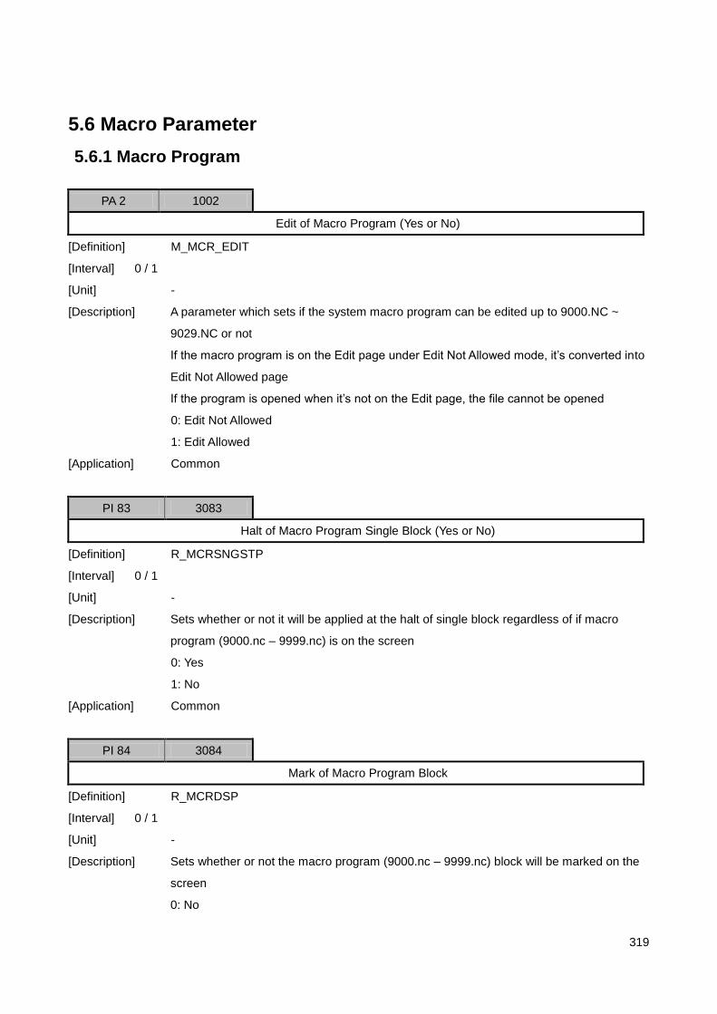
319
5.6 Macro Parameter
5.6.1 Macro Program
PA 2 1002
Edit of Macro Program (Yes or No)
[Definition] M_MCR_EDIT
[Interval] 0 / 1
[Unit] -
[Description] A parameter which sets if the system macro program can be edited up to 9000.NC ~
9029.NC or not
If the macro program is on the Edit page under Edit Not Allowed mode, it‟s converted into
Edit Not Allowed page
If the program is opened when it‟s not on the Edit page, the file cannot be opened
0: Edit Not Allowed
1: Edit Allowed
[Application] Common
PI 83 3083
Halt of Macro Program Single Block (Yes or No)
[Definition] R_MCRSNGSTP
[Interval] 0 / 1
[Unit] -
[Description] Sets whether or not it will be applied at the halt of single block regardless of if macro
program (9000.nc – 9999.nc) is on the screen
0: Yes
1: No
[Application] Common
PI 84 3084
Mark of Macro Program Block
[Definition] R_MCRDSP
[Interval] 0 / 1
[Unit] -
[Description] Sets whether or not the macro program (9000.nc – 9999.nc) block will be marked on the
screen
0: No

320
1: Yes
[Application] Common
PI 105 3105
Macro Program Call T Code
[Definition] R_TMCRPG
[Interval] 9000 / 9009
[Unit] -
[Description] A parameter which enters No. of macro program (9000.nc – 9009.nc) which is called
when T code is commanded
If it‟s „0,‟ No. 9000 macro program is called
[Application] Lathe not included
PI 106 3106
Whether or Not There is Macro Call When T Code is Called
[Definition] R_TMD (T Code Mode)
[Interval] 0 / 1
[Unit] -
[Description] A parameter which sets whether or not macro program (9000.nc – 9009.nc) is called
when T code is commanded
0: No
1: Yes
[Application] Lathe not included

321
5.6.2 Macro Variable
PI 74 3074
Initialization of Global Macro Variable at Reset
[Definition] R_GMCRCLR
[Interval] 0 / 1
[Description]
Applied to global macro #100 through #199
Decides if the macro value will be set to „0‟ when RESET or EMG STOP is pressed
0: Yes
N: No
[Application] Common

322
5.6.3 Macro Call G Code / M Code
PI 85 / 94 3085 / 3094
Macro Program Call G Code
[Definition] R_MCRG
[Interval] 0 / 255.9
[Unit] -
[Description] A parameter which enters G Code No. to call macro program (9010.nc – 9019.nc) with G
Code
G Code calls the programs (from 9010 to 9019 in order)
Among G code, 0, 1, 2, and 3 will be ignored (can be set to one digit below decimal point)
[Application] Common
PI 95 / 104 3095 / 3104
Macro Program Call M Code
[Definition] R_MCRM
[Interval] 0 / 255
[Unit] -
[Description] A parameter which enters M Code No. to call macro program (9020.nc – 9029.nc) with M
Code
M Code calls the programs (from 9020 to 9029 in order)
Among M code, 0 and 30 will be ignored
[Application] Common

323
5.7 Axis Parameter
5.7.1 Servo & Spindle Common Parameter
PS 1*
Axis Type Setup
[Definition] SAXISTP
[Interval] 0/2
[Description] SAXISTP
0: Unused axis
1: Servo axis
2: Spindle axis
1. Sets the unused axis to „0‟
2. Sets servo axis in servo axis setup range and spindle axis in spindle axis setup range
3. Sets speed-type PLC axis to spindle axis
PS 2*
Axis Port No. Setup
[Definition] SAXDVID
[Interval] 0/32
[Description] 1. Matches axis No. and axis port No. as much as possible
2. The axis port in use can change by changing axis port No.
PS 3*
Interface Method between CNC and Drive
[Definition] SSRVINTF
[Interval] 0/1
[Description] SSRVINTF
0: SERCOS Interface
1: Analog Interface

324
5.7.2 Servo Axis Setup
1) Control Axis Setup
PS 21*
Axis Feed Type Setup
[Definition] SVMTNTP
[Interval] 0/4
[Description] SMTNTP
0: Unused
1: Linear axis (When speed-type servo is used)
2: Rotation axis (When speed-type servo is used)
3: Linear axis (When position-type servo is used)
4: Rotation axis (When position-type servo is used)
PS 25*
Use of Return to Drive Origin (Yes or No)
[Definition] SVDZRN
[Interval] 0/1
[Description] SMTNTP
0: No
1: Yes
It‟s set when return-to-drive origin function is used in SERCOS Drive
PS 32*
Synchronous Control Master Axis No. Setup
[Definition] SVPMSYN
[Interval] 0/32
[Notice] Master axis No. must be earlier than Slave axis No.

325
2) Error Compensation Setup
PS 44*
Backlash Rate
[Definition] SVBCKLSH
[Interval] 0.0000/9.9999
[Unit] mm, inch, deg
[Description] The backlash compensation is applied after return-to-origin is completed
For more information, refer to “return-to-origin parameter setup”
PS 47
Friction Compensation Value
[Definition] SVSTICCP
[Interval] 0.000/9.999
[Unit] Voltage, Velocity Data Scale
[Description] The friction compensation value which is set to the following type depending on feed
direction compensates the friction after being added to control ouput value
[Notice] Be informed that it‟s immediately applied when the parameter changes
(+) Direction Feed
(-) Direction Feed
+SVSTICC
P
-SVSTICCP

326
PS 53*
Pitch Error Compensation Void Setup
[Definition] SVPITDS
[Interval] 0/1
[Description] OPITDS
0: Pitch Error Compensated
1: Pitch Error Not Compensated
A pitch error compensation method is as follows:
Index ….. 102 103 104 105 106 107 …..
Compensation Rate
….. 0.003 0.002 0.001 0.002 0.003 0.002 …..
The compensation value is calculated based on the following formula:
PS 57*
Pitch Error Input Interval
[Definition] SVPITDST
[Interval] 0.0000/99.9999
[Unit] mm, inch, deg
PS 58*
Pitch Error Table Index Correspondent to Origin
[Definition] SVPITZRN
[Interval] 0/200
Compensation
Rate
Origin
(+) Direction
Input Interval
Compensation Rate = Command Value – Actual Measurement Value

327
PS 59/258*
Pitch Error Table
[Definition] SVPIT
[Interval] -9.9999/9.9999
[Unit] mm, inch, deg
PS 259*
Position-type Servo Out-of-step Compensation Function
[Definition] SVPSROC
[Interval] 0/9999
[Unit] msec
[Description] In case a position-type servo (including step motor) is stepped out, the compensation is
made in SVPSROC after the feel is completed as a part of compensating the stepped-out
rate automatically.
This function is used only when an encoder exists
Sets it to „0‟ to disable this function
PS 260*
Position-type Servo Residual Pulse Compensation Function
[Definition] SVPSRMPL
[Interval] 0/99999
[Unit] pps
[Description] In case the timing is not matched between upper controller and pulse generator in a
position-type servo (including step motor), a minute residual pulse can be observed
SVPSRMPL is the pulse rate when this residual pulse is compensated
In general, it‟s set to the value of the position-type servo control resolution
[Notice] It must be set when a position-type servo is used

328
3) Gear Ratio Setup
PS 269*
Number of Machine Gear Teeth
[Definition] SVMGR
[Interval] 0/9999
PS 270*
Number of Motor Gear Teeth
[Definition] SVSGR
[Interval] 0/9999
PS 271*
Travel per Ball Screw Revolution
[Definition] SVBSPIT
[Interval] 0.0000/999.9999
[Unit] mm, inch
4) Encoder Setup
PS 279*
Use of Encoder (Yes or No)
[Definition] SVENCATP
[Interval] 0/1
[Description] SVENCATP
0: Yes
1: No
[Notice] No Encoder can be set only when a position-type servo is used

329
PS 280*
Encoder Type
[Definition] SVENKD
[Interval] 0/1
[Description] SVENKD
0: Incremental Encoder
1: Absolute Encoder
PS 282*
Encoder Pulse Output Method
[Definition] SVENPW
[Interval] 0/1
[Description] SVENPW
0: Linear method
1: Modular method
PS 284*
Encoder Resolution (Resolution after Multiplying)
[Definition] SVENCRS
[Interval] 0/99999999
[Unit] Pulse
5) Position-type Servo Setup
PS 290*
Position-type Servo Control Resolution
[Definition] SVPSRES
[Interval] 0/99999999
[Unit] Pulse

330
6) Position Controller Setup
PS 305*
Open Loop Control
[Definition] SVOPCON
[Interval] 0/1
[Unit]
[Description] SVOPCON
0: Close Loop Control
1: Open Loop Control
It‟s for machine assembly test
It should always be OFF except special cases
PS 306
Position Control P Gain
[Definition] SVPOSKP
[Interval] 0.00/999.99
[Description]
[Speed-type Servo]
Machine Rigidity Example CKp [1/sec]
High High-precision machining tool 50 ~ 70
Average General machining tool 30 ~ 50
Low Timing belt / chain drive machine 10 ~ 30
Based on the table above, the position control P gain is decided as follows:
[Notice] Be informed that it‟s immediately applied when the parameter changes
[Position-type Servo]
In case of position-type servo, SVPOSKP is pulse rate gain (%)
It will have the following features. The value over 100% must be set
(Pulse Rate Gain : 100%) (Pulse Rate Gain : 125%)
SVPOSKP = CKp * [(POS Sampling Time * 2500)/Motor Max RPM]

331
PS 309
Synchronous Error Compensation Gain
[Definition] SVSYNCKP
[Interval] 0.00/999.99
[Description] In general, it‟s set lower than the position control P gain
[Notice] Be informed that it‟s immediately applied when the parameter changes
PS 312
Feed Forward Gain
[Definition] SVFFKP
[Interval] 0.00/9999.99
[Description] In order to enhance the response in servo system (CKf(%)), the feed forward gain is
calculated as follows:
SVPOSKP and CKp are used to set the position gain
If CKp is set to high, the response gets quicker
However, overshoot or machine noise gets worse as well
In general, CKf is set to 30%
[Notice] Be informed that it‟s immediately applied when the parameter changes
PS 325*
Tracking Error Allowable Range
[Definition] SVOVRUN
[Interval] 0/99.9
[Unit] mm , inch, deg
[Description] If a tracking error occurs by exceeding the setpoint range, an alarm goes off and all axes
servo-off
SVFFKP = 1000*[(2500/ Motor Max RPM) – ((1-0.01*CKf)*SVPOSKP)
/ (POS Sampling Time *CKp)]

332
PS 326*
Synchronous Error Allowable Range
[Definition] SVSYNCER
[Interval] 0.000/9.999
[Unit] mm , inch, deg
[Description] If a tracking error occurs by exceeding the setpoint range, an alarm goes off and all axes
servo-off
PS 328*
Maximum Speed Command Value
[Definition] SVMAXVLC
[Interval] 0/99999999
[Description] 1. Analog speed-type servo: Sets to 2(D/A Converter Bit – 1)
– 1
2. Analog position-type servo: Sets to maximum output pulse rate (pps)
PS 339*
D/A Converter Resolution, Velocity Data Scale
[Definition] SVDABIT
[Interval] D/A Converter Resolution : (8), 12, (14,16,24,32)
Velocity Data Scale : 0/99999999
[Unit] Bit, 1/RPM
[Description] In case of analog interface, SERCOS I/O Module is set to 12bit and Universal I/O Module
to 16bit.

333
7) I/O Polarity Setup
PS 400*
Encoder C-phase Polarity
[Definition] SVCPHSP
[Interval] 0/1
[Description] SVCPHSP
0: + Polarity
1: - Polarity
PS 401*
Encoder Direction
[Definition] SVENCDIR
[Interval] 0/1
[Description] SENCDIR
0: + Direction
1: - Direction
PS 405*
Servo Ready Polarity
[Definition] SVSRDYP
[Interval] 0/1
[Description] SVSRDYP
0: + Polarity
1: - Polarity
PS 407*
Servo Alarm Polarity
[Definition] SVSALP
[Interval] 0/1
[Description] SVSALP
0: + Polarity
1: - Polarity

334
PS 410*
Speed Command Polarity
[Definition] SVVLCMP
[Interval] 0/1
[Description] SVSRDYP
0: + Polarity
1: - Polarity
1. In case of motor congestion during a test run, the polarity is set to the CCW
2. When the axis feed direction is changed to the CCW, both encoder direction and speed
command polarity should be set to the CCW
PS 413*
Servo On Polarity
[Definition] SVSONP
[Interval] 0/1
[Description] SVSONP
0: + Polarity
1: - Polarity
PS 415*
Servo Reset Polarity
[Definition] SVRSTP
[Interval] 0/1
[Description] SVRSTP
0: + Polarity
1: - Polarity

335
8) Diagnosis Function Setup
PS 420*
Encoder Phase Alarm Detection (Yes or No)
[Definition] SVPHSAL
[Interval] 0/1
[Description] SVPHSAL
0: Yes
1: No
Phase Error is called against encoder A phase and B phase rule
Then, Encoder Phase Alarm goes off
Because the encoder pulse signal is ignored when phase error occurs, the continuous
phase error may cause a big problem in feedback
In turn, it could be a fatal blow on safety
Therefore, SVPHSAL must be set to „0‟
PS 422*
Number of Phase Error Accumulations which are Regarded as Encoder Phase Alarm
[Definition] SVPHSAN
[Interval] 0/9
[Description] More than SVPHSAN phase errors occur, it‟s regarded as Encoder Phase Alarm
For the safety, set it to „1‟
If SVPHSAN is set to „0,‟ the default value is recognized as „3‟
PS 423*
NC Operation Setup at Encoder Phase Alarm
[Definition] SVPHSOP
[Interval] 0/2
[Description] SVPHSOP
0: Sends alarm message only
1: Halts deceleration
2: Servo OFF
For the safety, SVPHSOP should be set to „2‟ except for special cases

336
PS 425*
Encoder C-phase Alarm Detection (Yes or No)
[Definition] SVCPHSAL
[Interval] 0/1
[Description] SVCPHSAL
0: Yes
1: No
Encoder C-phase alarm goes off when the position in which encoder C-phase signal is
detected is not constant
Encoder C-phase alarm usually occurs when encoder resolution parameter is incorrectly
set or due to layout error or noise
In other words, the encoder C-phase alarm means that the machine origin and machine
position differ from the actuality. Therefore, SVCPHSAL must be set to „0‟
For reference, the encoder C-phase alarm is detected only after return-to-origin is
completed
PS 428*
NC Operation Setup at Encoder C-phase Alarm
[Definition] SVCPHSOP
[Interval] 0/2
[Description] SVCPHSOP
0: Sends alarm message only
1: Halts deceleration
2: Servo OFF
For the safety, SVPHSOP should be set to „2‟ except for special cases
PS 431*
Servo Ready Alarm-regarded Signal Input Delay Time
[Definition] SVSRALT
[Interval] 0/9999
[Unit] msec
[Description] If Servo Ready signal is not entered for SVSRALT after Servo ON signal, Servo Ready
alarm goes off

337
5.7.3 Spindle Axis Setup
1) Control Axis Setup
PS 21*
Motor / Drive Type
[Definition] SPMTNTP
[Interval] 0/5
[Description] SMTNTP
0: Unused axis
1: General spindle
2: PLC junction control method spindle
3: Servo motor
2) Error Compensation Setup
PS 33/36*
Backlash Rate in Each Gear Shift
[Definition] SPBCKLSH
[Interval] 0.000/9.999
[Unit] deg
3) Gear Ratio Setup
PS 47*
Gear Shift
[Definition] SPGRNUM
[Interval] 0/4
[Description] In case there is no gear shift, it‟s set to Low Gear
PS 48 / 51*
Number of Spindle Motor Gear Teeth in Each Gear Shift
[Definition] SPSGR
[Interval] 0/9999

338
PS 52/55*
Number of Spindle Machine Teeth in Each Gear Shift
[Definition] SPMGR
[Interval] 0/999
PS 61 / 64*
Number of 10V Spindle Revolution in Each Gear Shift
[Definition] SPG10RPM
[Interval] 0/99999
[Unit] rpm
[Description] The setpoint is not based on the spindle motor
It must be set based on cutter
PS 65/68*
Maximum Number of Spindle Revolution in Each Gear Shift
[Definition] SPGMRPM
[Interval] 0/99999
[Unit] rpm
[Description] The setpoint is not based on the spindle motor
It must be set based on cutter
PS 69*
Number of Spindle Revolution at Gear Shifting
[Definition] SPGCRPM
[Interval] 0/999
[Unit] rpm

339
4) Encoder Setup
PS 86*
Encoder Locking Method
[Definition] SPENCATP
[Interval] 0/2
[Description] SPENCATP
0: No encoder
1: Spindle motor direct-coupled encoder
2: External encoder
PS 88*
Encoder Pulse Output Method
[Definition] SPENPW
[Interval] 0/1
[Description] SPENPW
0: Linear method
1: Modular method
PS 93
Encoder Resolution (Resolution after Multiplying)
[Definition] SPENCRS
[Interval] 0/99999999
[Unit] Pulse

340
5) Spindle Function Setup
PS 109
Spindle Rotation Speed Allowable Range
[Definition] SPAGR
[Interval] 0.0/100.0
[Unit] %
PS 110
Spindle Zero Speed Allowable Range
[Definition] SPZAGR
[Interval] 0.0/99.9
[Unit] Rpm
PS 121
Spindle Orientation Speed
[Definition] SPORNF
[Interval] 0/999
[Unit] rpm
PS 122
Spindle Orientation Direction
[Definition] SPORNDIR
[Interval] 0/1
[Unit] OORNPLT
0: + Direction
1: - Direction
PS 123
Spindle Orientation Offset
[Definition] SPORNOS
[Interval] -180.000/180.000
[Unit] deg

341
6) Position Controller Setup
PS 174/177
Position Mode P Gain in Each Gear Shift
[Definition] SPPOSKP
[Interval] 0.00/99999.99
[Reference] Refer to Servo Axis Position Gain Setup Method
[Notice] Be informed that it‟s immediately applied when the parameter changes
PS 183 / 186
Position Mode Feed Forward Gain in Each Gear Shift
[Definition] SPFFKP
[Interval] 0.00/99999.99
[Reference] Refer to Servo Axis Feed Forward Gain Setup Method
[Notice] Be informed that it‟s immediately applied when the parameter changes
PS 194*
Tracking Error Allowable Range
[Definition] SPOVRUN
[Interval] 0.0/999.9
[Unit] deg
[Description] If a tracking error occurs by exceeding the position mode setpoint range, an alarm goes
off and all axes servo-off
PS 196*
Maximum Speed Command Value
[Definition] SPMAXVLC
[Interval] 0/99999999
[Description] Analog speed-type servo: Sets to 2(D/A Converter Bit – 1)
– 1

342
PS 207*
D/A Converter Resolution, Velocity Data Scale
[Definition] SPDABIT
[Interval] D/A Converter Resolution : (8), 12, (14,16,24,32)
Velocity Data Scale : 0/99999999
[Unit] Bit, 1/RPM
[Description] In case of analog interface, SERCOS I/O Module is set to 12bit and Universal I/O Module
to 16bit.

343
PS 211
Input Voltage Offset Compensation Method
[Definition] SPOSVTP
[Interval] 0/1
[Description] SPOSVTP
0: Single offset method
1: Multiple offset method
[Single offset method]
Compensates the voltage offset by shifting voltage amount which is outputted to the
spindle drive (+/- direction) and using the inputted voltage offset
[Multiple offset method]
The voltage offset can be set against + / - direction up to 10 points
The compensation input method is as follows:
Param. ….. PS226 PS225 PS224 PS214 PS215 PS216 …..
Compensation ….. 0.03 -0.005 0.01 0.01 0.03 0.02 …..
-0 V +0 V
Compensation
+Voltage
Input Interval
-Voltage
+V
+RPM
Voltage Offset

344
PS 212
Input Voltage Offset (In Case of Single Offset Method)
[Definition] SPOSV
[Interval] -9.999/9.999
[Unit] Voltage
[Notice] Be informed that it‟s immediately applied when the parameter changes
PS 213
Voltage Offset Input Interval (In Case of Multiple Offset Method)
[Definition] SPOSVMG
[Interval] 0.0/99999.9
[Unit] Rpm
PS 214/223
CW Direction Input Voltage Offset (In Case of Multiple Offset Method)
[Definition] SPOSVMP
[Interval] -9.999/9.999
[Unit] Voltage
[Notice] Be informed that it‟s immediately applied when the parameter changes
PS 224/233
CCW Direction Input Voltage Offset (In Case of Multiple Offset Method)
[Definition] SPOSVMN
[Interval] -9.999/9.999
[Unit] Voltage
[Method] Be informed that it‟s immediately applied when the parameter changes

345
7) I/O Polarity Setup
PS 280*
Encoder C-phase Polarity
[Definition] SPCPHSP
[Interval] 0/1
[Description] SPCPHSP
0: + Polarity
1: - Polarity
PS 281*
Encoder Direction
[Definition] SPENCDIR
[Interval] 0/1
[Description] SPNCDIR
0: + Direction
1: - Direction
PS 285*
Servo Ready Polarity
[Interval] 0/1
[Description] SPSRDYP
0: + Polarity
1: - Polarity
PS 287*
Servo Alarm Polarity
[Definition] SPSALP
[Interval] 0/1
[Description] SPSALP
0: + Polarity
1: - Polarity

346
PS 290*
Speed Command Polarity
[Definition] SPVLCMP
[Interval] 0/1
[Description] SPSRDYP
0: + Polarity
1: - Polarity
1. In case of motor congestion during a test run, the polarity is set to the CCW
2. When the axis feed direction is changed to the CCW, both encoder direction and speed
command polarity should be set to the CCW
PS 293*
Servo On Polarity
[Definition] SPSONP
[Interval] 0/1
[Description] SPSONP
0: + Polarity
1: - Polarity
PS 295*
Servo Reset Polarity
[Definition] SPRSTP
[Interval] 0/1
[Description] SPRSTP
0: + Polarity
1: - Polarity

347
8) Diagnosis Function Setup
PS 300*
Encoder Phase Alarm Detection (Yes or No)
[Definition] SPPHSAL
[Interval] 0/1
[Description] SPPHSAL
0: Yes
1: No
Phase Error is called against encoder A phase and B phase rule
Then, Encoder Phase Alarm goes off
Because the encoder pulse signal is ignored when phase error occurs, the continuous
phase error may cause a big problem in feedback
In turn, it could be a fatal blow on safety
Therefore, SVPHSAL must be set to „0‟
PS 302*
Number of Phase Error Accumulations which are Regarded as Encoder Phase Alarm
[Definition] SPPHSAN
[Interval] 0/9
[Description] More than SVPHSAN phase errors occur, it‟s regarded as Encoder Phase Alarm
For the safety, set it to „1‟
If SVPHSAN is set to „0,‟ the default value is recognized as „3‟
PS 303*
NC Operation Setup at Encoder Phase Alarm
[Definition] SPPHSOP
[Interval] 0/2
[Description] SPPHSOP
0: Sends alarm message only
1: Halts deceleration
2: Servo OFF
For the safety, SVPHSOP should be set to „2‟ except for special cases

348
PS 311*
Servo Ready Alarm-regarded Signal Input Delay Time
[Definition] SPSRALT
[Interval] 0/9999
[Unit] msec
[Description] If Servo Ready signal is not entered for SVSRALT after Servo ON signal, Servo Ready
alarm goes off

349
5.8 I/O Setup Parameter
5.8.1 PLC Setup
1) PLC Setup
PP 1605*
Number of Level #2 Processes per Sampling
[Definition] OSTEP2
[Interval] 0/99999
[Unit] Step
[Description] Enters the number of steps per sampling for Level #2 Ladder program
It it‟s set to „0,‟ 600 steps are processed per sampling
2) I/O Configuration
I/O Configuration Table
I/O Group No. I/O Type (OOITY)
X/Y Joint Start Address (OOISAD)
X/Y Joint Count (OOINUM)
1
2
3
4
5
6
7
8

350
PP 1610/1617*
I/O Type
[Definition] OOITY
[Interval] 0/8
[Description] OSOITY
0: Unused
1: SERCOS I/O
2: CAN I/O
3: NC Board I/O
4: SERCOS Servo Drive I/O
5: S/W Operation Panel I/O
PP 1618/1625*
X/Y Joint Start Address
[Definition] OOISAD
[Interval] 0/255
PP 1626/1633*
X/Y Joint Count
[Definition] OOINUM
[Interval] 0/255
[Unit] X32 Point
[Description] Enters the total number of joints of I/O Group
Be aware that 32 joint points are the minimum
1. In case two 64-point CAN I/Os are used, it should be set to „4‟
2. In case three 4-point SERCOS Drives are used, it should be set to „3‟

351
5.8.2 Communication Setup
1) SERCOS Communication Setup
PP 1710*
Use of SERCOS Monitoring (Yes or No)
[Definition] OSSDBG
[Interval] 0/10
[Description] As a communication monitoring parameter, it must be set to „0‟ except for special cases
PP 1715*
Data Interface
[Definition] OSSDI
[Interval] 0, 1
[Description] OSSDI
0: 8Bit / 1: 16Bit
PP 1716*
Baud Rate
[Definition] OSSBRATE
[Interval] 0/999999
PP 1720*
Optical Cable Luminosity Adjustment
[Definition] OSSBIM
[Interval] 0/9
PP 1721*
Number of Slave Modules
[Definition] OSSSNUM
[Interval] 0/36
[Description] Number of Slave Modules = Number of I/O Modules + Number of Sercos Drives

352
PP 1733/1736*
I/O Module ID
[Definition] OSSIOID
[Interval] 0/4
[Description] I/O Modules are supported up to 4 units
Unused I/O module is set to „0‟
PP 1737/1740*
I/O Module Type
[Definition] OSSIOTP
[Interval] 0/30
[Description]
H/W Type Setpoint
SERCOS I/O Module (Ver 1.0 ~1.5)
0 : Incremental Encoder Interface
1 : Absolute Encoder Interface
SERCOS I/O Module (Ver 1.6)
5 : Incremental Encoder Interface
6 : Absolute Encoder Interface
Universal I/O Module 10
PP 1753/1756*
Communication Time
[Definition] OSSCMT
[Interval] 0/80000
[Unit] usec
PP 1757/1760*
AT Time
[Definition] OSSATT
[Interval] 0/8000
[Unit] usec

353
PP 1761/1764*
POS of MDT
[Definition] OSSPMDT
[Interval] 1/128
PP 1765/1768*
Length of All MDT
[Definition] OSSLMDT
[Interval] 2/4096
PP 1769/1772*
MDT Time
[Definition] OSSMDT
[Interval] 0/8000
[Unit] usec
PP 1773/1776*
End Time of MDT
[Definition] OSSEMDT
[Interval] 0/8000
[Unit] usec
PP 1777/1780*
AT Length
[Definition] OSSATL
[Interval] 0/64
PP 1781/1784*
MDT Length
[Definition] OSSMDTL
[Interval] 0, 2048

354
PP 1793/1796*
Number of Speed-type Servo Modules (In Case of Universal I/O)
[Definition] OSSVSN
[Interval] 0/8
PP 1797/1800*
Number of Position-type Servo Modules (In Case of Universal I/O)
[Definition] OSSPSN
[Interval] 0/8
PP 1801/1804*
Number of Input I/O Joint Modules (In Case of Universal I/O)
[Definition] OSSIION
[Interval] 0/8
PP 1805/1808*
Number of Output I/O Joint Modules (In Case of Universal I/O)
[Definition] OSSOION
[Interval] 0/8

355
5.9 Special Function Parameter
5.9.1 Z Gap Trace Function
PM 7005* 27005
Use of Z Gap Trace Function (Yes or No)
[Definition] OZGMD
[Interval] 0/2
[Description] OZGMD
0: No
1: Yes
[Notice] In case a parameter changes, it‟s applied after the system is rebooted
PM 7007* 27007
A/D Board Type
[Definition] OZGADTP
[Interval] 0/9
[Unit] OZGADTP
0: Unused
1: Internal A/D
2: Advantech PCI-1731
3: Advantech PCL-816
[Notice] In case a parameter changes, it‟s applied after the system is rebooted
PM 7012/7015* 27012/27015
Select Z Gap Trace Axis
[Definition] OZGAX
[Interval] 0/32
[Description] In order to use Z Gap Trace function, enter axis No. (up to 4 axes)
[Notice] In case a parameter changes, it‟s applied after the system is rebooted
PM 7024/7031 27024/27031
Z Gap Trace Control Range
[Definition] OZGRNG
[Interval] -99999.9999/99999.9999
[Unit] mm, inch
[Description] 1. Enters minimum / maximum orderly

356
2. If the control range is exceeded during Z Gap Trace, an alarm goes off and the axis
travel halts
PM 7040/7043 27040/27043
Z Gap Trace Command Position
[Definition] OZGCP
[Interval] -9999.9999/9999.9999
[Unit] mm, inch
PM 7052/7055 27052/27055
How to Feed to Z Gap Trace Sensor Detection Area
[Definition] OZGSPM
[Interval] 0/1
[Description] OZGIPM
0: Transfer to parameter setpoint position
1: Use the sensor‟s detection area OFF signal (ZGFAR)
In case an axis is off from the sensor measurement range when Z gap trace is started,
select the method to transfer the axis to the area within the sensor measurement range
PM 7056/7059 27056/27059
Z Gap Trace Sensor Detection Position Setup
[Definition] OZGSP
[Interval] -99999.9999/99999.9999
[Unit] mm, inch
[Description] It‟s applied when OZGSPM setpoint is „0‟
PM 7060/7063 27060/27063
Amount of Shift after Being Transferred to Z Gap Trace Sensor Detection Area
Nozzle Measurement Position (Sensor Position)
OZGCP (+ Direction)

357
[Definition] OZGSPSF
[Interval] -99.9999/99.9999
[Unit] mm, inch
[Description] 1. It‟s applied when OZGSPM setpoint is „0‟
2. In case the amount of shift is detected, Z Gap Trace is started after the axis is shifted
to the position in which ZGFAR signal gets high
PM 7064/7068 27064/27068
Feed Speed to Z Gap Trace Sensor Detection Area
[Definition] OZGSPF
[Interval] -99999.9/99999.9
[Unit] mm/min, inch/min
[Description] The axis can be transferred to the CCW depending on the polarity of sensor output signal
If it‟s transferred to the CCW, the setpoint sign should be reversely set
PM 7068/7071 27068/27071
Delay After Being Transferred to Z Gap Trace Sensor Detection Area
[Definition] OZGSPDT
[Interval] 0/9999
[Unit] msec
[Description] Sets the time delay until the positioning starts to the command position after being
transferred to the sensor detection area
PM 7076/7079 27076/27079
Feed Speed at Positioning to Z Gap Trace Command Position
[Definition] OZGIPF
[Interval] -99999.9/99999.9
[Unit] mm/min, inch/min
[Description] The axis can be transferred to the CCW depending on the polarity of sensor output signal
If it‟s transferred to the CCW, the setpoint sign should be reversely set
PM 7080/7083 27080/27083
IN-position Range After Being Positioned to Z Gap Trace Command Position
[Definition] OZGIPINP
[Interval] 0/9.9999
[Unit] mm, inch

358
PM 7088/7091 27040/27043
Z Gap Trace Control Gain
[Definition] OZGGAIN
[Interval] -999.9/999.9
[Unit] %
[Description] The axis cannot be converged depending on the polarity of sensor output signal
If it‟s not converged, the sign should be reversely set
PM 7100/7103* 27100/27103
Z Gap Trace Sensor Output Type Setup
[Definition] OZGSTP
[Interval] 0/1
[Description] OZGSTP
0: Linear output
1: Non-linear output
PM 7104/7107 27104/27107
Distance from Z Gap Trace Sensor Output Singal OV (In Case of Linear Output)
[Definition] OZGS0VD
[Interval] 0/999.9999
[Unit] mm, inch
[Description] In case the sensor output signal is OV, the distance between nozzle (cutter) and an object
is entered
PM 7108/7111 27108/27111
Distance per 1V Z Gap Trace Sensor Output Singal (In Case of Linear Output)
[Definition] OZGS1VD
[Interval] -999.9999/999.9999
[Unit] mm, inch
PM 7116/7119 27116/27119
Index Included in Z Gap Trace Sensor Output Signal OV (In Case of Non-linear Output)
[Definition] OZGS0VIX
[Interval] 0/20
PM 7120/7123 27120/27123
Input Interval Against Z Gap Trace Sensor Output Signal (In Case of Non-linear Output)

359
[Definition] OZGSVG
[Interval] 0.0000/99.9999
[Unit] Voltage
PM 7124/7207 27124/27207
Distance Table Against Z Gap Trace Sensor Output Signal (In Case of Non-linear Output)
[Definition] OZGSTB
[Interval] -9999.9999/9999.9999
[Unit] mm, inch
PM 7233/7236 27233/27236
Noise Filter1 Time Constant
[Definition] OZGFTS
[Interval] 0/999
[Unit] msec
[Description] Noise Filter1 is used when a noise is often observed in feedback signal from sensor
In case the filtering time constant is set to high, the filtering becomes more effective, but Z
Gap Trace function becomes worse
PM 7237/7240 27237/27240
Singal Allowable Change Width of Noise Filter2
[Definition] OZGFNKR
[Interval] 0.0000/9.9999
[Unit] voltage/sample
[Description] Sensor signal allowable change width per sampling is entered in Noise Filter2, which in
turn can remove the noise that instantly pops up
PM 7241/7244 27241/27244
Maximum Number of Noise Removal Sampling of Noise Filter2

360
[Definition] OZGFNKN
[Interval] 0/999
[Unit] sample
[Description] In case the sensor signal change width from Noise Filter2 is larger than OZGFNKR, the
noise which instantly pops up can be removed
In case the sensor signal change width is larger than OZGFNKR in the continuous
sampling, however, the previous signal is kept until the number of samplings in
OZGFNKN. After that, it‟s regarded as a normal signal
In case the noise is removed under OZGFNKR, at least more than 1 should be set to
OZGFNKN

361
5.9.2 Feed Speed Output Function
PM 7289/7291 27289/27291
Select Axis at Feed Speed Output
[Definition] OMFOAX
[Interval] 0/32
[Description] Calculates the vector speed against the axis set to OMFOAX and outputs it with
F201.0~F201.1F
PM 7295 27295
Base Feed at Feed Speed Output
[Definition] OMFORF
[Interval] 0/99999.9
[Unit] mm/min, inch/min
[Description] If it‟s set to „0,‟ the command feed is set to the base feed
PM 7296 27296
Base Output at Feed Speed Output
[Definition] OMFORO
[Interval] 0/9999999
MFOMAX
MFOMIN
MFORO
MFORF Feed
Output

362
PM 7297 27297
Maximum Output Value at Feed Speed Output
[Definition] OMFOMAX
[Interval] 0/9999999
PM 7298 27298
Minimum Output Value at Feed Speed Output
[Definition] OMFOMIN
[Interval] 0/9999999
PM 7299 27299
Uniform Interval Signal Output Range at Feed Speed Output
[Definition] OMFCFR
[Interval] 0/100
[Unit] %
[Description] In case the difference between the command speed and the actual speed in terms of feed
speed is within the setpoint, F200.24 signal gets high

363
5.9.3 Punch Press Control Function
Punch Press Control Function
PM 7305* 27305
Use of Punch Press Function (Yes or No)
[Definition] OPPCMD
[Interval] 0/1
[Description] OPPCMD
0: No
1: Yes
PM 7308 27308
Use of Rapid Feed Speed / Acceleration and Deceleration Time Variable Control (Yes or No)
[Definition] OPPG0CTL
[Interval] 0/1
[Description] OPPG0CTL
0: No
1: Yes
If OPPG0CTL is set to „0,‟ the general rapid feed speed and acceleration / deceleration
time constant are applied
If OPPG0CTL is set to „1,‟ the rapid feed speed and the acceleration / deceleration time
constant become variable and controlled depending on the length of block
The speed and acceleration / deceleration time constant which are applied depending on
the length of each block are decided as follows by the setpoint in OPPG0X(Y)F and
OPPG0X(Y)T:
Length of Block (S) Rapid Feed Speed Rapid Feed Time
Constant
0 ≤ S < OPPG0RD(#1) OPPG0X(Y)F(#1) OPPG0X(Y)T(#1)
OPPG0RD(#1) ≤ S < OPPG0RD(#2) OPPG0X(Y)F(#2) OPPG0X(Y)T(#2)
OPPG0RD(#2) ≤ S < OPPG0RD(#3) OPPG0X(Y)F(#3) OPPG0X(Y)T(#3)
OPPG0RD(#3) ≤ S < OPPG0RD(#4) OPPG0X(Y)F(#4) OPPG0X(Y)T(#4)
OPPG0RD(#4) ≤ S < OPPG0RD(#5) OPPG0X(Y)F(#5) OPPG0X(Y)T(#5)
OPPG0RD(#5) ≤ S < OPPG0RD(#6) OPPG0X(Y)F(#6) OPPG0X(Y)T(#6)
OPPG0RD(#6) ≤ S < OPPG0RD(#7) OPPG0X(Y)F(#7) OPPG0X(Y)T(#7)
OPPG0RD(#7) ≤ S OPPG0X(Y)F(#8) OPPG0X(Y)T(#8)

364
PM 7321/7327 27321/27327
Base Length in Each Phase of Rapid Feed Block
[Definition] OPPG0RD
[Interval] 0.000/9999999.999
[Unit] mm, inch
PM 7328/7335 27328/27335
Feed in Each Phase of X-axis Rapid Feed Block
[Definition] OPPG0XF
[Interval] 0.000/99999.9
[Unit] mm/min, inch/min
PM 7336/7343 27336/27343
Acceleration / Deceleration Time in Each Phase of X-axis Rapid Feed Block
[Definition] OPPG0XT
[Interval] 0/9999
[Unit] msec
PM 7344/7351 27344/27351
Feed in Each Phase of Y-axis Rapid Feed Block
[Definition] OPPG0YF
[Interval] 0.000/99999.9
[Unit] mm/min, inch/min
PM 7352/7359 27352/27359
Acceleration / Deceleration Time in Each Phase of Y-axis Rapid Feed Block
[Definition] OPPG0YT
[Interval] 0/9999
[Unit] msec
PM 7374/7381 27374/27381
PPF Signal Output Time (Before X-axis Feed is Completed) Setup
[Definition] OPPXDT1
[Interval] 0/9999
[Unit] msec

365
PM 7382/7389 27382/27389
PPF Signal Output Time (Before Y-axis Feed is Completed) Setup
[Definition] OPPYDT1
[Interval] 0/9999
[Unit] msec
PM 7390 27390
PPF Signal Output Time (Before C-axis Feed is Completed) Setup
[Definition] OPPCDT1
[Interval] 0/9999
[Unit] msec
PM 7391 27391
Delay Time (for PPF Signal to Become Low by PPE Signal) Setup
[Definition] OPPDT2
[Interval] 0/9999
[Unit] msec
PM 7392 27392
Delay Time (to Move to Next Block When PPFS Signal is High) Setup
[Definition] OPPDT3
[Interval] 0/9999
[Unit] msec
PM 7393 27393
Delay Time (between Positioning and PPF Signal Output in Nibbling Mode) Setup
[Definition] OPPDT4
[Interval] 0/9999
[Unit] msec
PM 7394 27394
Delay Time (between NPFIN Signal and Next Block in Nibbling Mode) Setup
[Definition] OPPDT5
[Interval] 0/9999
[Unit] msec
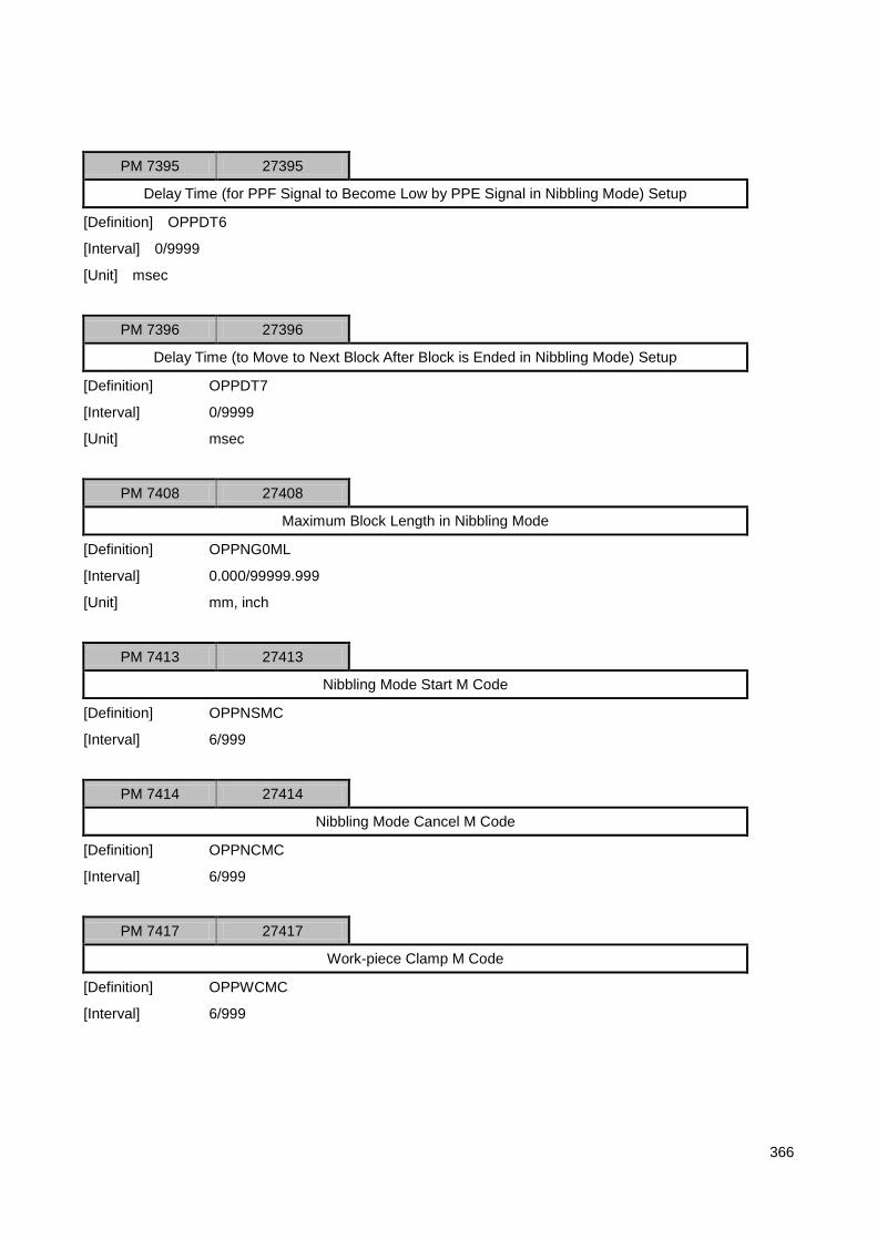
366
PM 7395 27395
Delay Time (for PPF Signal to Become Low by PPE Signal in Nibbling Mode) Setup
[Definition] OPPDT6
[Interval] 0/9999
[Unit] msec
PM 7396 27396
Delay Time (to Move to Next Block After Block is Ended in Nibbling Mode) Setup
[Definition] OPPDT7
[Interval] 0/9999
[Unit] msec
PM 7408 27408
Maximum Block Length in Nibbling Mode
[Definition] OPPNG0ML
[Interval] 0.000/99999.999
[Unit] mm, inch
PM 7413 27413
Nibbling Mode Start M Code
[Definition] OPPNSMC
[Interval] 6/999
PM 7414 27414
Nibbling Mode Cancel M Code
[Definition] OPPNCMC
[Interval] 6/999
PM 7417 27417
Work-piece Clamp M Code
[Definition] OPPWCMC
[Interval] 6/999

367
PM 7418 27418
Work-piece Unclamp M Code
[Definition] OPPWUMC
[Interval] 6/999

368
5.9.4 Lapping Control Function
Lapping Control Function
PM 7438* 27438
Use of Lapping Control Function (Yes or No)
[Interval] 0/1
[Description] OLAPMD
0: No
1: Yes
PM 7441* 27441
Lapping Rotation Axis Setup
[Interval] 0/2
[Description] A(1), B(2)
PM 7445 27445
Lapping Cutter Head‟s X(Y)-axis Direction Offset
[Interval] -999.9999/999.9999
[Unit] mm, inch
[Description]
OLAPTHX = + LenH
OLAPTHZ = - LenV
PM 7446 27446
Lapping Cutter Head‟s Z-axis Direction Offset
[Definition] OLAPTHZ
[Interval] -999.9999/999.9999
[Unit] mm, inch
X(Y)
Z
LenV
LenH

369
5.10 HMI Parameter
5.10.1 HMI Setup
PA 328 1328
Use of [Alt+X] (Yes or No)
[Definition] M_ALTX
[Interval] 0 / 1
[Unit] -
[Description] 0: Yes
1: No
[Application] Common
PP 1*
Use of SOFT OP (Yes or No)
[Definition] M_SOFTOP
[Interval] 0 / 1
[Unit] -
[Description] A parameter which sets if the S/W which is implemented from OP panel is used or not
In order to use SOFT OP, the resolution must be higher than 800 x 600
0: No
1: Yes
[Application] Common
PP 3 / 4*
SOFT OP Screen Size
[Definition] M_SOPSIZE
[Interval] 1 / 9999
[Unit] -
[Description] Sets the size of screen when SOFT OP is used
The two values are applied to Width x Length
If it‟s set to „0,‟ 800 x 600 is applied
[Application] Common

370
PP 1900*
Main Screen Size (0: 640*480, 1: 800*600)
[Definition]
[Interval] 0 / 1
[Unit] -
[Description] Sets the main screen size
[Application] Common
STR* caMachine
System Name
[Description] Stores the system name which will be marked on system booting logo
The string should be 30 long at maximum (30 letters for English and 15 letters for Korean)
The system name has a format of “System Name”+”Version.txt”
ex) HX-MC 2.1(01.10.8)
[Application] Common
PP 20*
TPG-applied System Type
[Definition] M_MACH_TYPE
[Interval] 0 / 2
[Unit] -
[Description] A parameter which enters the type of current system
The system type can be mostly categorized into three: Lathe Type, Milling Type, and NCT
Type
0 stands for Milling Type, 1 for Lathe Type, and 2 for NCT Type
The graphic processing can differ depending on this parameter
[Application] Common

371
5.10.2 Axis Mark Setup
PA 406* 1406
Use of Automatic Axis Mark (Yes or No)
[Definition] M_AUTOAXIS
[Interval] 0 / 1
[Description] Sets if the page will be automatically linked or fixed depending on axis setup
If it‟s set to „0,‟ it‟s automatically interlocked based on the axis setup
If it‟s set to „1,‟ the axes from 1 to 10 are only supported
The axes are more than 5, the coordinate setup screen should be added
If it‟s set to „1‟ or the axis setup is over 10, the screen is displayed based on the axis mark
information defined in Axis.txt
In case a user wants to configure the axis display page differently, see Axis architecture and make
Axis.txt
[Application] Common
PA 330 1330
Axis Screen Display FORMAT
[Definition] M_AXISFMT
[Interval] -
[Description] Enters format for the number of digits that stand for axis
If it‟s set to „0,‟ the default is 10.3
If 10.3 is entered, for example, it‟s stated as “±xxxxx.xxx” on the screen (10digits in total,
three digits below the decimal points)
This setup is basically based on mm unit system
In case of inch unit system, the maximum number of digits is the same with one digit
longer below the decimal point
[Application] Common
PA 329 1329
Diameter / Radius Mark Setup
[Definition] M_DIARAD
[Interval] 0 / 1
[Description] A parameter which sets if the coordinate axis is marked with diameter or radius
In case of lathe, this parameter is set to „1‟
X-axis among PA [331~362] is set to „1‟
0: Radius

372
1: Diameter
[Application] Common
PA 331 / 362 1331 / 1362
Application of Diameter / Radius Mark by Axis (Yes or No)
[Definition] M_CANDIARAD
[Interval] 0 / 1
[Description] Sets the axis to which the method which is set at diameter / radius mark setup parameter
is applied
The axis which is set to „1‟ means the axis to which diameter / radius parameter setup is applied
The axis which is set to „0‟ means the axis which has no influence from the diameter / radius mark setup
parameter
It‟s marked as radius
[Application] Common
PA 0 1000
Inch/Metric Mark Unit System
[Definition] M_ DSPUN
[Interval] 0 / 1
[Description] A parameter which sets if the unit system which is applied to the length information on the
screen is inch unit system or metric unit system
In case the unit system has changed to inch system, „Application of Inch / Metric by Axis
(Yes or No)‟ should be set (PA[374 ~ 405] among HMI parameters) because a degree unit
system not an inch unit system is marked in rotation axis
0: Metric
1: Inch
[Application] Common
PA 374 / 405 1374 / 1405
Inch / Metric Mark by Axis (Yes or No)
[Definition] M_INCHMET
[Interval] 0 / 1
[Description] Sets the axis to which the method which is set at diameter / radius mark setup parameter
is applied
The axis which is set to „1‟ means the axis to which inch / metric parameter setup is applied
The axis which is set to „0‟ means the degree axis which has no influence from the inch / metric
parameter

373
It‟s marked as radius
[Application] Common
STR* caAxis
Axis Labels (Max. 2 character )
[Description] Area in which the labels against the axes are stored
32 axes are allocated
The string is 2 long (2 letters for English and 1 letter for Korean at maximum)
[Application] Common
PA 418/439 1418/1439
Coordinate Mark by Axis (Yes or No)
[Definition]
[Interval] 0 / 1
[Unit] -
[Description] A parameter which sets if the coordinate of axis (up to 32 axes) is marked or not
It‟s basically marked if the axis is set
Against the axis to which 1 is set, however, it‟s not marked
In case of the axis which is continuously processed to a unilateral direction, the maximum
digits (10 digits) are exceeded
In this case, the number of digits on the screen cannot be aligned
Therefore, the axis should be set to „1‟

374
5.10.3 Font Setup
PP 6 / 12*
Text Font Width
[Definition] M_FONTW
[Interval] 5 / 50
[Unit] -
[Description] Enters the font width
The font types are from 0 through 5 (5 is not used at present)
In case the input value is 0, the default size is used with the size 0:6, 1:10, 2:16, and 3:35
[Application] Common
PP 13 / 19*
Text Font Height
[Definition] M_FONTH
[Interval] 5 / 50
[Unit] -
[Description] Enters font height
The font types are from 0 through 5 (5 is not used at present)
In case the input value is 0, the default size is used with the size 0:12, 1:20, 2:33, and
3:70
[Application] Common

375
5.11 Setup-related Parameter
5.11.1 Coordinate System
PA 1368 / 1376 2368 / 2376
Shift of Work-piece Coordinate System
[Definition] R_WKSFT
[Interval] -99999.999 / 99999.999, -9999.9999 / 9999.9999
[Unit] mm, inch
[Description] 9 axes such as X,Y,Z,A,B,C,U,V, and W
[Application] Lathe / Milling
Machine Coordinate System
Relative Coordinate
System
Work-piece Coordinate System
Shift Work-piece Coordinate System
Relative Coordinate
System Offset
G54 – G59
Work-piece Coordinate
System Offset
Shift of Work-piece
Coordinate System
Input Relative Position
Machine Position
(X,Y,Z)
Current Position
(X,Y,Z)
Relative Position
(X,Y,Z)
Shift Current Position
(X,Y,Z)

376
PA 1377 / 1385 2377 / 2385
G54 Work-piece Coordinate System by Each Axis
[Definition] R_WKCDG54
[Interval] -99999.999 / 99999.999, -9999.9999 / 9999.9999
[Unit] mm, inch
[Description] 9 axes such as X,Y,Z,A,B,C,U,V, and W
Refer to the figure of work-piece coordinate system shift
[Application] Common
PA 1386 / 1394 2386 / 2394
G55 Work-piece Coordinate System by Each Axis
[Definition] R_WKCDG55
[Interval] -99999.999 / 99999.999, -9999.9999 / 9999.9999
[Unit] mm, inch
[Description] 9 axes such as X,Y,Z,A,B,C,U,V, and W
Refer to the figure of work-piece coordinate system shift
[Application] Common
PA 1395 / 1403 2395 / 2403
G56 Work-piece Coordinate System by Each Axis
[Definition] R_WKCDG56
[Interval] -99999.999 / 99999.999, -9999.9999 / 9999.9999
[Unit] mm, inch
[Description] 9 axes such as X,Y,Z,A,B,C,U,V, and W
Refer to the figure of work-piece coordinate system shift
[Application] Common
PA 1404 / 1412 2404 / 2412
G57 Work-piece Coordinate System by Each Axis
[Definition] R_WKCDG57
[Interval] -99999.999 / 99999.999, -9999.9999 / 9999.9999
[Unit] mm, inch
[Description] 9 axes such as X,Y,Z,A,B,C,U,V, and W
Refer to the figure of work-piece coordinate system shift
[Application] Common

377
PA 1413 / 1421 2413 / 2421
G58 Work-piece Coordinate System by Each Axis
[Definition] R_WKCDG58
[Interval] -99999.999 / 99999.999, -9999.9999 / 9999.9999
[Unit] mm, inch
[Description] 9 axes such as X,Y,Z,A,B,C,U,V, and W
Refer to the figure of work-piece coordinate system shift
[Application] Common
PA 1422 / 1430 2422 / 2430
G59 Work-piece Coordinate System by Each Axis
[Definition] R_WKCDG59
[Interval] -99999.999 / 99999.999, -9999.999 / 9999.999
[Unit] mm, inch
[Description] 9 axes such as X,Y,Z,A,B,C,U,V, and W
Refer to the figure of work-piece coordinate system shift
[Application] Lathe / Milling
PA 1432 2432
Use of Work-piece Coordinate System Shift (Yes or No)
[Definition] R_USEWKSFT
[Interval] 0 / 1
[Unit] -
[Description] 0: No, 1:Yes
[Application] Common

378
PA 1433 / 1441 2433 / 2441
Input Relative Position
[Definition] R_INRELPOS
[Interval] -99999.999 / 99999.999, -9999.9999 / 9999.9999
[Unit] mm, inch
[Description] 9 axes such as X,Y,Z,A,B,C,U,V, and W
In order to locate the relative position between base cutter and the other cutter when the
work-piece coordinate system is set using the base cutter, random coordinate system
(relative coordinate system) can be set
Refer to the figure of work-piece coordinate system shift
[Application] Common
PI 77 3077
Maintain Work-piece Coordinate System
[Definition] R_OFFCAN
[Interval] 0 / 1
[Unit] -
[Description] A parameter of maintaining work-piece coordinate system at reset
0: Maintain
1: Cancel
In order to use Resume Program, it should be set to „Maintain‟
[Application] Common

379
5.11.2 Compensation & Offset
PA 600 1600
Tool Nose Type
[Definition] R_NSTP
[Interval] 0 / 9
[Unit] -
[Description] Enters tool nose type No. by tool offset No. as shown in the figure below:
[Application] Lathe
PA 664 / 727 1664 / 1727
Tool Nose Radius
[Definition] R_NSRD
[Interval] 0 / 99.999, 0 / 9.9999
[Unit] mm, inch
[Description] Enters tool nose radius by tool offset No.
[Application] Lathe
PA 728 / 791 1728 / 1791
X-axis Geometry Offset Compensation (GX)
[Definition] R_XTOST
[Interval] -99999.999 / 99999.999, -9999.9999, 9999.9999
[Unit] mm, inch
[Description] Enters X-axis cutter offset compensation
[Application] Lathe
0,9
1
3
2
4
5
6
7
8

380
PA 792 / 855 1792 / 1855
Y-axis Geometry Offset Compensation (GY)
[Definition] R_YTOST
[Interval] -99999.999 / 99999.999, -9999.9999, 9999.9999
[Unit] mm, inch
[Description] Enters Y-axis cutter offset compensation
[Application] Lathe
PA 856 / 919 1856 / 1919
Z-axis Geometry Offset Compensation (GZ)
[Definition] R_ZTOST
[Interval] -99999.999 / 99999.999, -9999.9999, 9999.9999
[Unit] mm, inch
[Description] Enters Z-axis cutter offset compensation
[Application] Lathe
PA 920 / 983 1920 / 1983
X-axis Cutter Wear-out Compensation (WX)
[Definition] R_XTWR
[Interval] -99.999 / 99.999, -9.9999 / 9.9999
[Unit] mm, inch
[Description] Enters X-axis cutter wear-out compensation
[Application] Lathe
PA 984 / 1047 1984 / 2047
Y-axis Cutter Wear-out Compensation (WY)
[Definition] R_YTWR
[Interval] -99.999 / 99.999, -9.9999 / 9.9999
[Unit] mm, inch
[Description] Enters Y-axis cutter wear-out compensation
[Application] Lathe

381
PA 1048 / 1111 2048 / 2111
Z-axis Cutter Wear-out Compensation (WZ)
[Definition] R_ZTWR
[Interval] -99.999 / 99.999, -9.9999 / 9.9999
[Unit] mm, inch
[Description] Enters Z-axis cutter wear-out compensation
[Application] Lathe
PA 1112 / 1239 2112 / 2239
Cutter Diameter Compensation (D)
[Definition] R_TDAOST
[Interval] -999.999 / 999.999, -99.9999 / 99.9999
[Unit] mm, inch
[Description] Enters compensation by compensation address to use it at cutter diameter compensation
[Application] Common
PA 1240 / 1367 2240 / 2367
Cuter Height Compensation (H)
[Definition] R_THTOST
[Interval] -999.999 / 999.999, -99.9999 / 99.9999
[Unit] mm, inch
[Description] Enters compensation by compensation address to use it at cutter height compensation
[Application] Milling
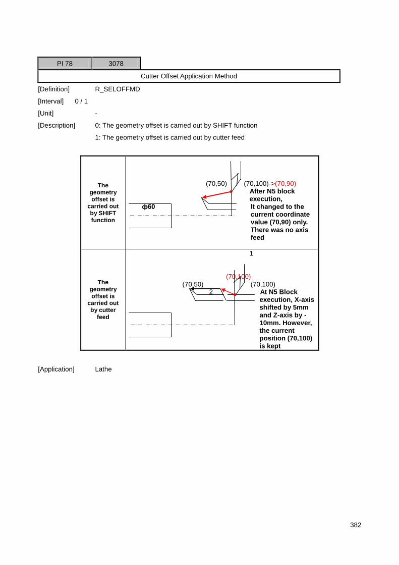
382
PI 78 3078
Cutter Offset Application Method
[Definition] R_SELOFFMD
[Interval] 0 / 1
[Unit] -
[Description] 0: The geometry offset is carried out by SHIFT function
1: The geometry offset is carried out by cutter feed
The geometry offset is
carried out by SHIFT function
(70,50) (70,100)->(70,90) After N5 block
execution, ф60 It changed to the
current coordinate value (70,90) only. There was no axis feed
The geometry offset is
carried out by cutter
feed
1 (70,100) (70,50) (70,100) 2 At N5 Block
execution, X-axis shifted by 5mm and Z-axis by -10mm. However, the current position (70,100) is kept
[Application] Lathe

383
5.12 Status Information
5.12.1 IPR Information
SV 11 4011
IPR Operation (Yes or No)
[Definition] R_IPRRUN
[Interval] 0 / 1
[Unit] -
[Description] A parameter which informs the status if the code interpreter is operated after auto cycle
start is executed
(0: NO, 1: Yes)
[Application] Common
SV 12 4012
IPR HEART BEAT
[Definition] R_HEARTBEAT
[Interval] 0 / 1
[Unit] -
[Description] A parameter which informs the status if a code interpreter can be operable
If the value continuously changes, it‟s a normal status
If the value does not change, it‟s an abnormal status
Under abnormal status, an alarm “Code Interpreter Is Not Be Enabled” goes off
[Application] Common
SV 15 4015
Wait EOM (Yes or No)
[Definition] R_WEOM
[Interval] 0 / 1
[Unit] -
[Description] A parameter which informs the status in which a code interpreter waits until the motor
stops
In case it‟s set to „1,‟ it‟s not proceeded to the next bock
In case it‟s set to „0,‟ it‟s proceeded
0: No / 1: Yes
[Application] Common

384
SV 16 4016
AF Use
[Definition] R_BFULL
[Interval] 0 / 100
[Unit] -
[Description] A parameter which states AF use
AF is a buffer in which the information between a code interpreter and path generator is
shared
The use is included within 0 – 100
In case the use is 100, the operation speed of code interpreter is faster than path
generator (machine drive) and then slowing down
In case the use is less than 100, it‟s the state that the code interpreter runs fast
[Application] Common
5.12.2 S/W Module Information
SV 20 4020
IPO RUN State
[Description] OIPORUN
0: IPO Idle
1: IPO Run
SV 21 4021
IPO Heart Bit
SV 22 4022
POS Heart Bit
SV 23 4023
PLC Heart Bit
SV 30 4030
Timer

385
5.12.3 Version Information
SV 3 4003
HMI Version
[Description] The system version is stated in the format of x.x
„x.‟ means reorganization while „.x‟ means upgrading
[Application] Common
SV 4 4004
HMI Beta Version
[Description] It used when it‟s released as test version before being released as official version
The type is the same with HMI version above
[Application] Common
SV 13 4013
IPR Version
[Description] The version No is stated in the format of x.x
„x.‟ means reorganization while „.x‟ means upgrading
SV 17 4017
IPR Beta Version
[Description] It used when it‟s released as test version before being released as official version
The type is the same with IPR version above
[Application] Common
SV 24 4024
IPO Version
SV 25 4025
POS Version
SV 26 4026
PLC Version
SV 27 4027

386
PLC Ladder Version
SV 28 4028
H/W Version
SV 29 4029
H/W ROM Version

387
5.12.4 Axis Information
SV 41 / 50 4041 / 4050
Actual Axis No. of CNC Control Axis
[Definition] OCNCAXNO
[Interval] 0/32

388
5.12.5 Machine Information
SV 51 / 82 4051 / 4082
Offset from Machine Coordinate System to Work-piece Coordinate System
[Definition] OWCRDOS
[Interval] 0.0000/99999.9999
[Unit] mm, inch, deg
SV 83 / 114 4083 / 4114
Current Position (Absolute Coordinate) based on Work-piece Coordinate System
[Definition] OWCPOS
[Interval] 0.0000/99999.9999
[Unit] mm, inch, deg
SV 115 / 146 4115 / 4146
Relative Coordinate
[Definition] ORELPOS
[Interval] 0.0000/99999.9999
[Unit] mm, inch, deg
SV 215 / 246 4215 / 4246
Handle Interrupt
[Definition] OHIINT
[Interval] 0.0000/99999.9999
[Unit] mm, inch, deg
SV 247 / 278 4247 / 4278
Residual Distance
[Definition] ORDIST
[Interval] 0.0000/99999.9999
[Unit] mm, inch, deg
SV 379 / 410 4379 / 4410
Servo Position Deviation (Tracking Error)
[Definition] OFLWER
[Interval] -99.999/99.999
[Unit] mm, inch, deg

389
SV 411 / 442 4411 / 4442
Synchronous Position Deviation (Synchronous Error)
[Definition] OSYNCER
[Interval] -99.999/99.999
[Unit] mm, inch, deg
SV 443 4443
Pitch Error at Rigid Tapping
[Definition] ORGDPER
[Interval] -99.999/99.999
[Unit] mm, inch
SV 542 4542
C-phase (Yes or No)
[Definition] OCPHSST
[Interval] 0h/FFFFFFFFh
[Unit] Bit
[Description] OCPHSST
0: No
1: Yes
SV 543 / 574 4543 / 4574
C-phase Pulse
[Definition] OCPHS
[Interval] 0/999999
[Unit] Pulse
SV 675 4675
Feed Override
[Definition] OFOVST
[Interval] 0/200
[Unit] %
SV 676 4676
Rapid Override
[Definition] ORFOVST

390
[Interval] 0/100
[Unit] %
SV 681 4681
Spindle Override
[Definition] OSPDOVST
[Interval] 0/200
[Unit] %
SV 721 4721
Feed Speed Commanded (F Command Value)
[Definition] OFCMD
[Interval] 0.0/99999.9
[Unit] mm/min, inch/min
SV 722 4722
Vector Feed Speed Commanded (Override, Acceleration / Deceleration Considered)
[Definition] OCVECF
[Interval] 0.0/99999.9
[Unit] mm/min, inch/min

391
SV 755 / 786 4755 / 4786
Actual Feed Speed
[Definition] OAF
[Interval] 0.0/99999.9
[Unit] mm/min, inch/min, deg/min
SV 787 4787
Actual Vector Feed Speed
[Definition] OAVECF
[Interval] 0.0/99999.9
[Unit] mm/min, inch/min, deg/min
SV 792 4792
Spindle Command Speed (S Command Value)
[Definition] OSCMD
[Interval] 0/99999
[Unit] rpm
SV 793 4793
Spindle Command Speed (Override Considered)
[Definition] OCSPRPM
[Interval] 0/99999
[Unit] rpm
SV 794 4794
Actual Spindle Speed (Override Considered)
[Definition] OASPRPM
[Interval] 0/99999
[Unit] rpm

392
SV 800 4800
Dwell Count
[Definition] ODWCNT
[Interval] 0/9999
[Unit] msec
SV 805/807 4805/4807
MPG Input Pulse
[Definition] OMPGCNT
[Interval] -99999999/99999999
[Unit] pulse
SV 820/851 4829/4851
Servo Control Output Value (Speed Command Value)
[Definition] OSDCTRLV
[Interval] -99999999/99999999

393
5.12.6 NC Program Execution-related Information
SV 866 4866
EOM
[Definition] OEOM
[Interval] 0/1
SV 867 4867
Error Block Number at IPR Interpretation
[Definition] OERBLKNO
[Interval] 0/999999
SV 873 4873
Block Number of MDI Program Currently in Operation
[Definition] OCMBLKNO
[Interval] 0/999999
SV 874 4874
Block Seek Address of MDI Program Currently in Operation
[Definition] OCMBLKSA
[Interval] 0/999999
SV 876 4876
Type of Block Currently in Operation
[Definition] OCBLKMTB
[Interval] 0/99
SV 881 4881
No. of Cutter Currently in Use
[Definition] OTNO
[Interval] 0/999

394
SV 882 4882
Cutter Compensation Offset No.
[Definition] OTROS
[Interval] 0/999
SV 883 4883
Cutter Length Compensation Offset No.
[Definition] OTLOS
[Interval] 0/999
SV 887 / 918 4887/ 4918
Current Coordinate of Cutter Path Inspection
[Definition] OTPGPOS
[Interval] -99999.9999/99999.9999
[Unit] mm, inch, deg

395
5.12.7 Machine Information
SN 205 / 236 6205 / 6236
Command Machine Position
[Definition] OMCPOS
[Interval] -99999.9999/99999.9999
[Unit] mm, inch, deg
SN 237 / 268 6237 / 6268
Actual Machine Position
[Definition] OMCRPOS
[Interval] -99999.9999/99999.9999
[Unit] mm, inch, deg
SN 269 / 300 6269 / 6300
Actual Absolute Machine Position
[Definition] OMCARPOS
[Interval] -9999999.9999/9999999.9999
[Unit] mm, inch, deg
SN 319 / 350 6319 / 6350
Machine Position Value with Skip Signal
[Definition] OSKPPOS
[Interval] -99999.9999/99999.9999
[Unit] mm, inch, deg
SN 451 / 482 6451 / 6482
Encoder Value
[Definition] OEC
[Interval] 0/999999999999
[Unit] Pulse
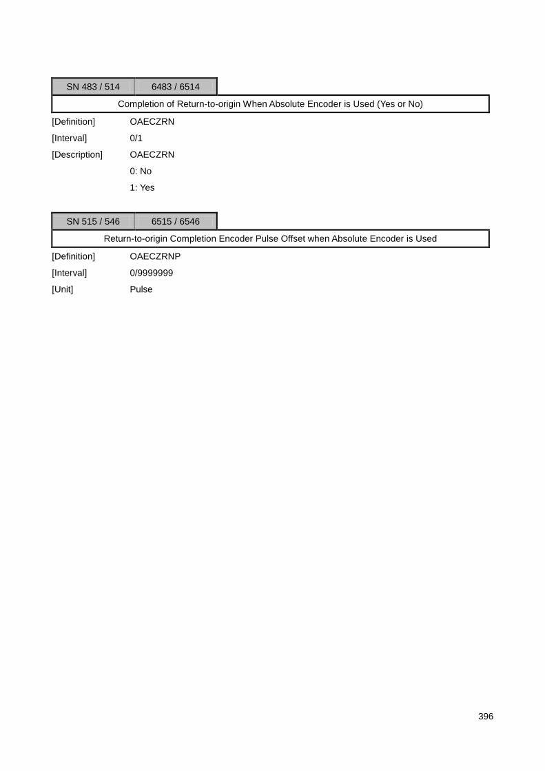
396
SN 483 / 514 6483 / 6514
Completion of Return-to-origin When Absolute Encoder is Used (Yes or No)
[Definition] OAECZRN
[Interval] 0/1
[Description] OAECZRN
0: No
1: Yes
SN 515 / 546 6515 / 6546
Return-to-origin Completion Encoder Pulse Offset when Absolute Encoder is Used
[Definition] OAECZRNP
[Interval] 0/9999999
[Unit] Pulse

397
5.12.8 NC Program Execution-related Information
SN 714 6714
Main Program Block No.
[Definition] OMBLKNO
[Interval] 0/999999
SN 715 6715
Main Program Block Seek Address
[Definition] OMBLKSA
[Interval] 0/999999
SN 716 6716
Block No. of Program Currently in Use
[Definition] OCBLKNO
[Interval] 0/999999
SN 717 6717
Block Seek Address of Program Currently in Use
[Definition] OCBLKSA
[Interval] 0/999999
SN 718 / 749 6718 / 6749
G Code Modal Value
[Definition] OMDLG
[Interval] 0.0/99.9
SN 752 6752
Number of Main Program Repetition
[Definition] OMLOOPN
[Interval] 0/999

398
SN 753 / 762 6753 / 6762
Program Restart Sequence Information (Return Block Number for Restart)
[Definition] ORETBLK
[Interval] 0/999999
SN 763 / 772 6763 / 6772
Program Restart Sequence Information (Return Seek Address for Restart)
[Definition] ORETSEEK
[Interval] 0/999999
SN 773 / 782 6773 / 6782
Program Restart Sequence Information (Loop Block Number for Restart)
[Definition] OLOOPBLK
[Interval] 0/999999
SN 783 / 792 6783 / 6792
Program Restart Sequence Information (Loop Seek Address for Restart)
[Definition] OLOOPSA
[Interval] 0/999999
SN 793/ 802 6793/ 6802
Number of Searches of „Start Program Restart Subprogram‟
[Definition] ORECNT
[Interval] 0/999999
SN 803 6803
Modal Feed
[Definition] OSNF
[Interval] 0/99999

399
SN 804 6804
Modal S Code
[Definition] OSNSCODE
[Interval] 0/99999
SN 805 6805
Modal M Code
[Definition] OSNSM
[Interval] 0/99

400
5.12.9 Z Gap Trace
SV 1500/1503 5500/5503
Z Gap Trace Control Position
[Definition] OZGPOS
[Interval] -99999.9999/99999.9999
[Unit] mm, inch
SV 1504/1507 5504/5507
Z Gap Trace Control Error
[Definition] OZGERR
[Interval] -9999.9999/9999.9999
[Unit] mm, inch

401
5.12.10 System S Parameter
SV 2 4002
If Program is in Storage (Yes or No)
[Definition] M_PROGSAVE
[Interval] 0 / 1
[Unit] -
[Description] A parameter which sets if a program is in storage in EDIT
0: No
1: Yes
[Application] Common
SN 0 6000
Operation Time
[Definition] M_OPERTIME
[Interval] -
[Unit] HH:MM:SS
[Description] Serial No. for operation time
States the total time from POWER ON to current position
If it exceeds 20,000 hours, it‟s automatically initialized to „0‟ (about 2 years)
[Application] Common
SN 1 6001
Cutting Time
[Definition] M_CUTTIME
[Interval] -
[Unit] HH:MM:SS
[Description] Serial No. for cutting time
States the total time from Cycle Start to current position
[Application] Common

402
SN 2 6002
Total Cutting Time
[Definition] M_TCUTTIME
[Interval] -
[Unit] HH:MM:SS
[Description] Serial No. for1` total cutting time
If it exceeds 20,000 hours, it‟s automatically initialized to „0‟ (about 2 years)
[Application] Common

403
5.12.11 Program S Parameter
SV 10 4010
System Alarm for Macro Program
[Definition] R_MCRALM
[Interval] 0 / 1
[Unit] -
[Description] A parameter to set a system alarm (“Macro Program Alarm”) during macro program
preparation
If „1‟ is entered to #4010 during macro program operation, the alarm message occurs
0: No
1: Yes
[Application] Common
SV 11 4011
IPR Run (Yes or No)
[Definition] R_IPRRUN
[Interval] 0 / 1
[Unit] -
[Description] A parameter which informs if a code interpreter is run after the auto cycle start is activated
0: No
1: Yes
[Application] Common
SV 12 4012
IPR HEART BEAT
[Definition] R_HEARTBEAT
[Interval] 0 / 1
[Unit] -
[Description] A parameter which informs the status if a code interpreter can be operable
If the value continuously changes, it‟s a normal status
If the value does not change, it‟s an abnormal status
Under abnormal status, an alarm “Code Interpreter Is Not Be Enabled” goes off
[Application] Common
SV 14 4014

404
Program Information Interface Method
[Definition] R_PTYPE
[Interval] 0 / 2
[Unit] -
[Description] A parameter for a code interpreter to interface NC program information
It‟s used in the inside of system only
AUTO operation is run by File Access while MDI operation is run by Direct Access and
DNC operation by DNC Access
(0:File Access, 1:DNC Access, 2:Direct Access)
[Application] Common
SV 15 4015
Wait EOM (Yes or No)
[Definition] R_WEOM
[Interval] 0 / 1
[Unit] -
[Description] A parameter which informs the status in which a code interpreter waits until the motor
stops
In case it‟s set to „1,‟ it‟s not proceeded to the next bock
In case it‟s set to „0,‟ it‟s proceeded
0: No
1: Yes
[Application] Common
SV 16 4016
AF Use
[Definition] R_BFULL
[Interval] 0 / 100
[Unit] -
[Description] A parameter which states AF use
AF is a buffer in which the information between a code interpreter and path generator is
shared
The use is included within 0 – 100
In case the use is 100, the operation speed of code interpreter is faster than path
generator (machine drive) and then slowing down
In case the use is less than 100, it‟s the state that the code interpreter runs fast
[Application] Common

405
SV 18 4018
TPG (Yes or No)
[Definition] R_TPG
[Interval] 0 / 1
[Unit] -
[Description] Informs if it‟s TPG or not
This parameter can be used as system macro variable in NC program
0: No
1: Yes
[Application] Common
SN 100 6100
If Power is Failed during Auto Operation (Yes or No)
[Definition] R_RUNEND
[Interval] 0 / 1
[Unit] -
[Description] Under AUTO mode, it‟s set to „1‟ when a cycle is started in the system
Decides if power is failed during the operation by the information above
It‟s used when the program is restarted with the flag which is prepared for the end of run
by the power failure
0: Power failure during non-AUTO operation
1: Power failure during AUTO operation
[Application] Common
SN 101 6101
Cutting Count
[Definition] R_CUTCNT
[Interval] 0
[Unit]
[Description] A parameter which states the cutting counts until now
It automatically increases if it meets M30 or M02 in CNC
It can be entered to „0‟
It‟s used to create a message with regard to the target cutting count parameter
[Application] Common

406
SN 102 / 111 6102 / 6111
Store Work-piece Coordinate Basic Offset
[Definition] R_COORDOFF
[Interval] -99999.999 / 99999.999
[Unit] mm / inch
[Description] It‟s used to store work-piece coordinate system basic offset to maintain the work-piece
coordinate system
Offset is applied when the system is booted or converted into MDI mode
[Application] Common
SN 112 / 121 6112 / 6121
Store Work-piece Coordinate System Shift Offset
[Definition] R_COORDSFT
[Interval] -99999.999 / 99999.999
[Unit] mm / inch
[Description] It‟s used to store work-piece coordinate system shift offset to maintain the work-piece
coordinate system
Offset is applied when the system is booted or converted into MDI mode
[Application] Common
SN 122 / 131 6122 / 6131
Store Cutter Length Offset
[Definition] R_TLENOFF
[Interval] -99999.999 / 99999.999
[Unit] mm / inch
[Description] It‟s used to store cutter length offset to maintain the work-piece coordinate system
Offset is applied when the system is booted or converted into MDI mode
[Application] Common

407
SN 132 / 141 6132 / 6141
Local Coordinate System Offset
[Definition] R_LOCALOFF
[Interval] -99999.999 / 99999.999
[Unit] mm / inch
[Description] It‟s used to store local coordinate system offset to maintain the work-piece coordinate
system
Offset is applied when the system is booted or converted into MDI mode
[Application] Common
SN 142 / 151 6142 / 6151
Lathe Geometric Offset
[Definition] R_GEOOFF
[Interval] -99999.999 / 99999.999
[Unit] mm / inch
[Description] It‟s used to store lathe geometric offset to maintain the work-piece coordinate system
Offset is applied when the system is booted or converted into MDI mode
[Application] Common
SN 152 / 161 6152 / 6161
Lathe Wear-out Offset
[Definition] R_WEAROFF
[Interval] -99999.999 / 99999.999
[Unit] mm / inch
[Description] It‟s used to store lathe wear-out offset to maintain the work-piece coordinate system
Offset is applied when the system is booted or converted into MDI mode
[Application] Common

408
5.12.12 STR Parameter
STR caSysPath
Directory in Which A System Execution File Exists
[Description] Directory which controls the system operation data files
[Application] Common
STR caPLCFile
PLC Program Name
[Description] PLC program name which is selected when a system is booted
[Application] Common
STR caMapFile
MAP File Name
[Description] MAP file name which is selected when a system is booted
[Application] Common
STR caAxis
Axis Labels
[Description] Area in which the labels against the axes are stored
32 axes are allocated
The string is 30 long (30 letters for English and 15 letters for Korean at maximum)
[Application] Common
STR caMachine
System Name
[Description] Stores the system name which will be marked on system booting logo
The string should be 30 long at maximum (30 letters for English and 15 letters for Korean)
[Application] Common

409
STR caNCPath
Directory in which NC Program File by Channel Exists
[Description] Basic directory which stores NC program
The inputted directory is run as basic directory in the program
[Application] Common
STR caErrProg
NC Program Interpretation Error Program Name
[Description] Program name when an error in NC program interpretation occurs
[Application] Common
STR caMainProg
Selected Main Program Name
STR caSubProg
Subprogram (Called in AUTO Mode) Name
STR caMDIProg
Subprogram (Called in MDI Mode) Name
STR caSeqProg
Program Name When Subprogram is Called

410
6 Warning Alarm List
6.1 Warning / Status List
6.1.1 System-related Warning / Status
F_91000 Invalid Input Value
[Description] In case an invalid value is entered at the time of input of a parameter or each set value
[Solution] Refer to the description and enter the correct value.
F_91001 INPUT Not Allowed
[Description] In case it‟s tried to change a parameter under the setup in which it can not be entered
[Solution] Enter RESET or PASSWORD and make the setup in which it can be entered. Then, it
should be entered.
F_92000 Can Not be Selected During Auto Operation
[Description] In case it‟s tried to select [Process Program] during AUTO operation
[Solution] Enter RESET and stop the AUTO operation. Then, select the program.
F_92001 Incorrect Password
[Description] In case an incorrect password is entered
[Solution] Refer to the user manual and enter a correct password.
F_92002 Call Program Can Not be Selected
[Description] A message that warns the program which has called a sub program to block the problem
of resuming the program not to be edited
[Solution] A program should not be edited.
A program can be edited only when the START Program of Program Resume is Select
Program.
F_92003 Communication Parity Alarm
[Description] The parity bit which is set in a parameter when DNC file is received or sent is not
observed in the data.
[Solution] Set the parity bit of CNC system and that of the counterpart‟s communication system
at the same level
In case the alarm goes off occasionally or after more than 10 bytes are transmitted, it may
be caused by the communication noise. Therefore, the cable should be shortened as

411
much as possible and Baudrate should be lowered.
In case of the system in which a problem is continuously detected, H/W repair of the
communication port is requested.
F_92004 Communication F_RAME Alarm
[Description] While DNC file is sent or received, the Baudrate of CNC system and that of the
counterpart‟s communication system differ to each other.
[Solution] Set the Baudrate of CNC system and that of the counterpart‟s communication system at
the same level
F_92005 Communication OVERRUN Alarm
[Description] While DNC file is sent or received, another data are entered even though the data
entered aren‟t lost.
[Solution] Communicate after operating CNC system and the counterpart‟s communication system
in turn
Lower the Baudrate
Turn off the power and connect the cable. Then, turn on the power and execute the
system
F_92006 Communication Protocol Alarm
[Description] Even though STOP signal is sent while DNC file is sent or received, the data keep being
entered.
[Solution] Set F_low Control of the counterpart‟s communication equipment to Xon / XoF_F_
Set the same parity bit for both CNC system and the counterpart‟s communication
equipment
Check the operation with output in case of CNC system and with input in case of the
counterpart‟s communication equipment
F_92007 Communication Parameter Alarm
[Description] The communication parameter exceeds its limits when DNC file is sent or received
[Solution] Refer to the manual and set the parameter within its limit
F_92008 Communication Port OPEN Alarm
[Description] When DNC file is sent or received, the communication port is not opened.
[Solution] Turns off and on the system
Check if COM1 and COM2 communication ports are installed in Windows NT

412
F_92009 Communication Port Alarm
[Description] A communication port error occurs when DNC file is sent or received
[Solution] Turn off and on the system
Check if other application programs are run well in Window NT and shut them off.
F_92010 File Open Alarm
[Description] A file for DNC operation is not opened when DNC file is sent or received
[Solution] Check if the file exists in Window NT and can be opened using the window explorer.
Check if other application programs get access to the file in Window NT and shut them off.
F_92011 Macro Editing Not Allowed
[Description] In case it‟s tried to open a macro program under the state that it can not be editable
[Solution] In order to make the macro editing enable, the system should be properly reset.
F_92012 Scheduling Mode
[Description] A message which shows that the mode under which the scheduling programs can be
consecutively processed is ON
F_92013 A Program Selected During Operation Can Not Be Changed
[Description] A main program and sub program which are selected during AUTO operation can not be
deleted and revised.
[Solution] Can be revised after the operation

413
6.1.2 Program-related Warning / Status
F_93000 LEX MAIN TABLE Improperly Configured
[Description] In case the system NC code analysis software is improperly configured
This alarm goes off when the incorrectly configured command is made
This alarm doesn‟t go off after the stabilization is completed. In case it‟s under
development, however, the alarm may go off. (LEX one of NC program commands)
F_93001 Undefined Character Exists
[Description] In case a character which is not supported in NC program is commanded
[Solution] Check the program and revise into a correct character command
F_93002 Number Exceeds Maximum Buffer Size
[Description] In case the number commanded in NC program exceeds 12 digits (including decimal
points, excluding symbols)
The maximum is set against the system instability by OverF_low.
[Solution] Have the number command within 12 digits
F_93003 The Number of LEX Tokens Exceeds Maximum Buffer Size
[Description] In case there are too many commands in a single block of NC program
The maximum commands are limited to 256 words. If this maximum is exceeded,
therefore, this alarm goes off. (LEX is one of NC program commands)
[Solution] Divide the alarmed block into several ones and then make a command
F_93004 Decimal Point is More Than One
[Description] In case the decimal point is more than one when the number which has the decimal point
in NC program is commanded
[Solution] Check the program and have the decimal point single
F_93005 The Parentheses are Not Matched Correctly
[Description] In case the parentheses are not properly matched when the number in NC program is
commanded
[Solution] Check the program and make the parentheses be matched correctly
F_93006 A Character Unusable in Mathematical Expression Exists
[Description] In case a character which should not be used in the mathematical expression in NC

414
program is commanded
For example, IF_, GOTO, G, M, S, and T can not be used in a mathematical formula.
[Solution] Check the program and have the command usable in a mathematical expression
F_93007 Incorrect Grammar
[Description] In case a incorrect grammar is commanded while commanding +, - ,*, /, cos, or sin from
the numerical formula in NC program (ex: 1 + * 10, cos*100)
[Solution] Check the program and correct the command
F_93008 Unallowable Macro Variable
[Description] In case the range of the macro variable which is commanded in NC program is incorrect
[Solution] The range of macro variable command should be commanded within the range specified
in the table below:
Macro No. MAP Description How Many
0 / 99 ML Local user macro variable - program 100
100 / 199 MGV Global user macro variable – non-storing program
100
200 / 699 MGN Global user macro variable – storing program 500
1000 / 2999 PA System macro variable 2,000
3000 / 3499 PI System macro variable 500
4000 / 5999 SV System macro variable 2,000
6000 / 6999 SN System macro variable 1,000
7000 / 7035 G System macro variable 36
7500 / 7535 F_ System macro variable 36
8000 / 8095 PM No. 234 Point 96
9000 / 10999 PU System macro variable 2,000
20000 / 29999 PM System macro variable 10,000
F_93009 TANGENT Calculation Error
[Description] In case -90 or 90 is commanded when Tangent is commanded in NC program
[Solution] Correct the wrong command and try again the operation
F_93010 SQUARE ROOT Calculation Error
[Description] In case a negative number is used in Square Root calculation in NC program
[Solution] Correct the wrong command and try again the operation
F_93011 Denominator Can Not Be Zero
[Description] In case zero is used as denominator when the numerical formula is commanded in NC
program

415
[Solution] Correct the wrong command and try again the operation
F_93012 Incorrect Grammar
[Description] In case the grammar commanded in NC program is incorrect
[Solution] Correct the wrong command and try again the operation
F_93013 YACC MAIN TABLE Improperly Configured
[Description] In case the system NC code analysis software is improperly configured
This alarm goes off when the incorrectly configured command is made
This alarm doesn‟t go off after the stabilization is completed. In case it‟s under
development, however, the alarm may go off. (YACC is a unit of NC program command
group, ex: IF_ _ GOTO _)
F_93014 The Number of YACC Tokens Exceeds Maximum Buffer Size
[Description] In case there are too many command groups in a single block of NC program
The maximum command groups are limited to 128. If this maximum is exceeded,
therefore, an alarm goes off. (YACC is a unit of NC program command group, ex: IF_ _
GOTO _)
[Solution] Divide the alarmed block into several ones and then make a command
F_93015 IPR Semaphores Can Not be Opened
[Description] In case HX system is damaged or OS or H/W system is unstable
This alarm goes off when IPR fails to open semaphores for interlock to carry out the internal process
It doesn‟t go off under the normal condition
[Solution] If the alarm goes off during the normal operation, turns off and on the power
Reinstall HX system 3
Reinstall OS
Check H/W (hard disk, memory, and main board) and replace the defect parts with new
ones
F_93016 Program End Without M02 or M30
[Description] In case the program end without M02 or M30 under AUTO mode in NC program
For your reference, it can be without M02 or M30 under MDI mode
[Solution] Add M02 or M30 at the last block of NC program
F_93017 Command Allowed At the Beginning of Block Only
[Description] In case the optional block skip in NC program is not commanded at the beginning of block

416
[Solution] Correct the optional block skip (/) to the beginning of block
F_93018 A Same Block Statement No. Exists
[Description] In case the same statement No. exists in NC program
A statement No. in a program should be unique
[Solution] Correct the statement No. not to be redundant
F_93019 The Number of Statement No. Exceeds Maximum Buffer Size
[Description] In case there are too many statement numbers that are commanded in NC program
Under the HX system, the statement numbers can be commanded up to 1000 by a program
[Solution] Remove an unnecessary statement No. or divide the program into sub programs and
reprepare it
F_93020 The Next Block Can Not Be Found
[Description] In case the next block can not be found in NC program
In case the next block is not found when GOTO or the other command is made
[Solution] Check if the statement No. is matched or the command is correct
F_93021 Incorrect Grammar to Call Subprogram
[Description] In case an incorrect grammar is used to call subprogram
[Solution] Refer to the program manual and call the subprogram with a correct grammar
F_93022 Subprogram is Called Too Often
[Description] In case a subprogram is consecutively called in NC program too often
Under HX system, it can be called up to 10 times including the main program
[Solution] Correct Subprogram Call Program and make sure that the subprogram is called up to 9
times.
F_93023 Program Already Called
[Description] In case the subprogram which has already been called is recalled
[Solution] Correct and make sure that the already called program is not called again
F_93024 No M99 is Found in Subprogram
[Description] In case M99 command is not observed in a subprogram
In a subprogram, M99 should exist to return to a prior program.
[Solution] Command M99 at the end of subprogram or any desired end position

417
F_93025 Incorrect M99 Grammar
[Description] In case a grammar is incorrect when M99 is commanded in the main program
[Solution] Refer to the program manual and make a command with a correct grammar on M99
F_93026 Too Many Loops
[Description] In case there are too many WHILE loops commanded in NC program
Under the HX system, they are supported up to 500
[Solution] Set the maximum WHILE Loop commands to 500
F_93027 No Start Found in Loop
[Description] In case END command exists without WHILE command in NC program
[Solution] Make sure that the number of WHILE commands and that of END commands are the
same. Besides, START and END of the connection should be clearly matched in the form
of frame
F_93028 Improper Loop Connection
[Description] In case several WHILE and END commands in NC program are improperly connected
[Solution] Make sure that the number of WHILE commands and that of END commands are the
same. Besides, START and END of the connection should be clearly matched in the form
of frame
F_93029 M Command Limits are Exceeded in a Single Block
[Description] In case the maximum number of M code commands which can be commanded in a single
block in NC program is exceeded
Under the HX system, they are supported up to 10
[Solution] Correct M code commands to less than 10
F_93030 Non-used G Code
[Description] In case G code which is not supported in NC program is commanded
[Solution] Refer to the program manual and have the correct G code command
F_93031 Commands Can Not be Made at the Same Time in a Single Block
[Description] In case more than one G code which uses X, Y, Z addresses among the one-shot G
codes is commanded in a single block
Only one G code is allowed in a single block above

418
[Solution] Refer to the program manual
In case of one-shot G code, have the command made after dividing the block into two
F_93100 Center of Arc Can Not be Found
[Description] In case R command in which the center of arc can not be found in NC program is made
In case R is shorter than a half of the distance between the start point and end point of the arc
An alarm may go off even though the distance is almost same. Then, the permissible errors can be
entered and adjusted by a parameter (PI 151 “permissible errors, radius of an arc)
[Solution] A slight error can be permitted with the adjustment of parameter.
Refer to the program manual and make sure that R command of radius of an arc is
correct
F_93101 Cycle Code Path Can Not be Created
[Description] In case the repetitive machining can not be done due to the inaccuracy between infeed
rate and infeed repetition in the cycle code command; or
In case the start / end point of configuration definition is the same with the start / end
point of cycle machining
[Solution] Refer to the program manual and correct the cycle code command
F_93102 Cycle Code Taper Rate is Too High
[Description] In case the cycle code taper is commanded larger than the actual cycle machining feed
rate
An alarm goes off due to the taper configuration which gets off the cycle feed path
[Solution] Either adjust the taper rate or the cycle feed path
F_93103 A Command Cannot be Made Within Cycle Configuration Block
[Description] In case the cycle is commanded again within the configuration definition block when the
cycle code is commanded;
the change of block position (ex: GOTO) is commanded in this block; or
a code which will not be in the configuration definition block is commanded
[Solution] Refer to the program manual and correct the command
F_93104 A Problem Found in Command on Cycle Configuration Block
[Description] In case there is a problem in Start / End command against the configuration definition
block by P and Q when the cycle code is commanded
[Solution] Refer to the program manual and check the command on the cycle code configuration
definition block. Then, correct the problem

419
F_93106 Invalid Tool Offset No.
[Description] In case the tool offset No. which is commanded in the program gets off the command
range
Under the HX system, it‟s supported up to 64 in case of rack and 128 in case of milling.
[Solution] Refer to the program manual and correct the offset number
F_93107 A Pointer Position of Program File Not Found
[Description] In case a file cannot be read when it‟s tried to read a block in NC program
In case either file or hard disk is damaged
[Solution] Check NC files with the other editor and solve the problem
In case the file is damaged, it should be recreated.
F_93108 Cannot be Read in Program File
[Description] In case a file cannot be read when it‟s tried to read a block in NC program
In case either file or hard disk is damaged
[Solution] Check NC files with the other editor and solve the problem
In case the file is damaged, it should be recreated.
F_93109 No Selected Program Found
[Description] In case the program file which is selected in HX system program doesn‟t exist
In case the previous file is either deleted or damaged
[Solution] Check if the program file exists
If it doesn‟t, a file should be added. If it does, check if the file is damaged and then solve the problem
F_93110 PACCESS Semaphores Can Not be Opened
[Description] In case HX system is damaged or OS or H/W system is unstable
This alarm goes off when IPR fails to open semaphores for interlock to carry out the internal process
It doesn‟t go off under the normal condition
[Solution] If the alarm goes off during the normal operation, turns off and on the power
Reinstall HX system
Reinstall OS
Check H/W (hard disk, memory, and main board) and replace the defect parts with new
ones
F_93111 Characters in a Single Block Limited Up to 300
[Description] The number of characters which can be commanded in NC program as a single block is

420
limited up to 300.
[Solution] Divide the program block into several blocks and then make a command
F_93112 Incorrect Arc Center Position
[Description] In case a command is made when an arc is not formed between the center point and the
start and end points
In case the distance between the start point and the center point is not the same with that
between the end point and the center point
The permissible errors against the difference above can be adjusted by a parameter (PI 151
“permissible errors, radius of an arc)
[Solution] A slight error can be permitted with the adjustment of parameter.
Refer to the program manual and make sure that the arc is properly commanded
F_93113 Chamfering and Rounding are Applied under Cutting Feed Command Only
[Description] In case Chamfering or Rounding is ordered when a command other than cutting feed
command is made
[Solution] Remove Chamfering or Rounding command when a command other than cutting feed
command is made
F_93114 Redundant Chamfering and Rounding Command
[Description] In case a command is repeated in a single block
Chamfering or rounding is made only once in a single block
[Solution] Refer to the program manual and make sure that chamfering or rounding is not repeated
F_93115 Single Axis Command Only Allowed in Chamfering or Rounding
[Description] In case a travel more than one axis is commanded against the command which can be
made at a single axis (I, J, K, C, R) travel
[Solution] In order to use chamfering or rounding functions at the travel of several axes, C
command or R command should be made.
Refer to the program manual and make a proper correction
F_93116 Chamfering and Rounding Command Value is Larger Than Feed Rate
[Description] In case chamfering and rounding value is larger than the feed rate
In this case, the chamfering and rounding can not be computed
[Solution] Refer to the program manual and make a correction by comparing the feed rate with the
chamfering / rounding value

421
F_93117 Cannot Get Next Block Information During Chamfering and Rounding
[Description] In case the next position information can not be obtained even though the position
information on the next block should be acquired in case of chamfering and rounding
If a program block process is changed when it‟s tried to get the next block position information or there is
no lineal feed command within the three blocks below the current block, the accurate next block cannot
be obtained.
[Solution] Adjust the program to make the lineal feed command come within the consecutive next
three blocks
F_93018 An Arc Cannot Come to Next Block During Chamfering and Rounding
[Description] In case an arc is commanded on the next block when it‟s tried to get the information on
the next block in order to perform Chamfering and Rounding
The lineal feed command should exist in the next block
[Solution] Adjust the program to make the lineal feed command come within the consecutive next
blocks
F_93119 Rounding Not Allowed At the Same Linear Feed
[Description] In case a next block travel is made on the same line, Rounding cannot be performed
[Solution] Adjust the program to make sure that the consecutive next blocks are not on the same
line
F_93120 Linear Transfer Only Allowed for Start and End of Calibration
[Description] At the start and end block of tool alarm definition, the linear feed such as rapid transfer or
cutting feed can only be commanded.
[Solution] Refer to the program manual and correct the command properly
F_93121 No Feed Command Found at the End Block of Cycle Configuration
[Description] At the end of cycle configuration block, the feed commands such as rapid transfer, cutting
feed, and circular interpolation should exist.
[Solution] Refer to the program manual and correct the command properly
F_93122 Axis Command Not Related with Plane is Found During Chamfering and Rounding
[Description] In case an axis command which is not related with the current set plane exists in
chamfering and rounding

422
Because the chamfering and rounding are performed on a plane, the plane-related axes should only be
commanded.
[Solution] Correct the program with the plane axis command
F_93123 The Maximum IJK Command in a Single Block is Exceeded When Macro is Called
[Description] In case I,J, K is used too much as macro parameter when Custom Macro is called (Max.
32)
[Solution] Reduce IJK commands
F_93124 Modal Macro Cannot be Called in Subprogram
[Description] Impossible to call modal custom macro (G66) in a subprogram
[Solution] Use another macro
F_93125 Multi Call of Modal Macro Exceeds The Limits
[Description] In case the maximum number of multi calls of modal macro (G66) is exceeded
The maximum number is 10 including the main program
[Solution] Reduce the maximum number of multi calls to 9
F_93126 Non-used M Code
[Description] In case M code which is not supported in NC program is commanded
[Solution] Make a correct command with M Code available
There is a directory called SYSTEM under the directory which has system executable file
(cncHX.exe). m.dat text file exists in this directory. If it‟s not found, M Code inspection will
not be carried out. In order to skip M code inspection, just delete the file. In order to make
M Code which is just commanded available, just enter the M Code number to m.dat file.
F_93127 Pitch Cannot be Computed During Rigid Tapping
[Description] In case a pitch cannot be computed during the rigid tapping
Either the spindle rate is 0 under RPM spindle command and MMPR feed command or it‟s the MPM
spindle command and MMPM feed command
[Solution] Refer to the program manual and correct the command
F_93128 String Exceeds Maximum Buffer Size
[Description] In case the consecutive string exceeds the maximum size of internal buffer
The maximum number of command-allowed consecutive string is 100.

423
[Solution] Make the number of string lower than 100
F_93129 Incorrect String Configuration Grammar
[Description] In case the end of string cannot be recognized
[Solution] Correct the end part in accordance with the string configuration grammar
F_93130 Target Process Amount is Reached
[Description] In case the setpoint which is set by a parameter (PA 1431 “Target Process Amount”) is
reached
The function to check the target process amount
[Solution] Check the process quantity and continue the next process
F_93131 User Halt of Macro Program
[Description] In case 1 is added to #4010 during macro program
It‟s used to ring the alarm in the macro program
[Solution] A user has to make a decision on its own and take a proper action because it‟s the
function problem of macro program.
F_93200 Multiple Threading Cycle Path Cannot be Created
[Description] In case infeed rate or infeed direction / angle is inaccurate during multiple threading cycle
[Solution] Refer to the program manual and correct the command
F_93204 Cannot be Commanded During Polar Coordinate Interpolation
[Description] G01, G02, and G03 only can be commanded during G112 polar coordinate interpolation
[Solution] Refer to the program manual and correct the command
F_93205 Cannot Pass Through Origin During Polar Coordinate Interpolation
[Description] In case the transfer command passes through the origin during G112 polar coordinate
interpolation
[Solution] Revise the program to make the transfer command not pass through the origin
F_93206 Grammatical Error at Cylindrical Interpolation Command
[Description] In case a grammatical error is observed when G107 cylindrical interpolation is
commanded
[Solution] Refer to the program manual and correct the cylindrical interpolation grammar just like
G107C_.

424
F_93207 Cannot be Commanded During Cylindrical Interpolation
[Description] G01, G02, and G03 only can be commanded during G107 cylindrical interpolation
[Solution] Refer to the program manual and correct the command
F_93208 Constant Cutting Speed Control Mode During Polar Coordinate and Cylindrical Interpolations
[Description] A feed per minute should be commanded during the polar coordinate interpolation and
the cylindrical interpolation
[Solution] Refer to the program manual and correct the command
F_93210 Not an Origin
[Description] In case the result after the inspection command (G27) is not the origin after returning to
the origin
[Solution] Correct the problem

425
6.1.3 IPO/POS-related Warning / Status
1) General Warning
95003 Not Allowed to Convert into AUTO Mode
[Description] Not allowed to convert into AUTO mode during DNC mode operation
[Solution] Try again after DNC mode operation is completed.
95004 Not Allowed to Convert into DNC Mode
[Description] Not allowed to convert into DNC mode during AUTO mode operation
[Solution] Try again after AUTO mode operation is completed.
95005 Not Allowed to Convert into MDI Mode
[Description] 1. Not allowed to convert into MDI mode unless the block execution is completed.
2. Not allowed to convert into MDI mode during high-speed machining
[Solution] 1. Try again after the block execution is completed.
2. Try again after the high-speed machining is completed.
95010 CCW (Counter Clockwise) Operation Selected
[Description] CCW (Counter Clockwise) operation status
95011 CCW (Counter Clockwise) Operation Completed
[Description] CCW (Counter Clockwise) operation is completed.
95020 Cutting Speed Not Commanded
[Description] In case there is no speed command during cutting feed when the feed per revolution is
commanded
[Solution] Make a cutting feed command
95021 Spindle Speed Not Commanded
[Description] In case there is no spindle speed command when the feed per revolution is commanded
[Solution] Make a spindle speed command
95023 Maximum Cutting Speed Limited
[Description] In case the cutting speed command exceeds the parameter setpoint
[Solution] 1. Adjust the cutting speed command
2. Check the parameter (PM2870, 2872, 2874) setpoint

426
2) Axis-control Warning
95105 Auto-returning to Origin
[Description] Auto-returning to the origin under AUTO mode
The same format from Axis #2 through Axis #32
- Axis #2 (95200~95231),
- Axis #3 (95300~85331),
:
- Axis #32 (98200~98231)

427
6.2 Alarm List
6.2.1 System-related Alarm
F_80000 Failed to Create Shared Memory
[Description] In case a shared memory is not created
This alarm can go off when a power is on when a system is unstable. However, this kind of situation
hardly occurs. Normally, this alarm goes off when a problem is found in RAM or the size is insufficient.
[Solution] Turn off and on HX system
Check H/W RAM size. If RAM is 32M or below, run cncHX32.exe
Increase RAM size
Replace RAM
Replace a main board
F_80001 Failed to Execute RTSS Process
[Description] In case Hard Real Time S/W is not implemented
In case a problem is found in Windows NT4.0, RTX4.2, or Hard Real Time S/W
[Solution] Turn off and on HX system
Reinstall HX S/W
Remove RTX4.2 and reinstall it
Back up the data in hard disk and format the hard disk / reinstall all software programs
Replace a main board
F_80002 Failed to Save MAP File
[Description] In case data can not be stored in hard disk
In case either the hard disk is defective or its size is insufficient
[Solution] Turn off and on HX system
Check the current memory state of hard disk and increase the size if necessary
Replace a hard disk
Replace a main board
F_80004 Decoder Not Enabled
[Description] In case a problem is detected while monitoring the software (IPR) which decodes NC
code among Hard Real Time Part (RTX4.2) software programs in SoF_t Real Time Part
(Windows NT4.0)
[Solution] Turn off and on HX system
Reinstall HX software

428
Remove RTX4.2 and reinstall it
Back up the data in hard disk and format the hard disk / reinstall all software programs
Replace a main board
F_80005 Path Generator Not Enabled
[Description] In case a path generator (IPO) which creates a path for motor transfer among Hard Real
Time Part (RTX4.2) software programs in SoF_t Real Time Part (Windows NT4.0) is not
enabled
[Solution] Turn off and on HX system
Reinstall HX software
Remove RTX4.2 and reinstall it
Back up the data in hard disk and format the hard disk / reinstall all software programs
Replace a main board
F_80006 PLC Not Enabled
[Description] In case PLC analyzing software among Hard Real Time Part (RTX4.2) software programs
in SoF_t Real Time Part (Windows NT4.0) is not enabled
[Solution] Turn off and on HX system
Reinstall HX software
Remove RTX4.2 and reinstall it
Back up the data in hard disk and format the hard disk / reinstall all software programs
Replace a main board
F_80007 Control Software Not Enabled
[Description] In case the control software (POS) such as SERCOS communication among Hard Real
Time Part (RTX4.2) software programs in SoF_t Real Time Part (Windows NT4.0) is not
enabled
[Solution] Turn off and on HX system
Reinstall HX software
Remove RTX4.2 and reinstall it
Back up the data in hard disk and format the hard disk / reinstall all software programs
Replace a main board
F_80008 RS232 Key Communication Error
[Description] In case a communication problem is detected during key input with RS232
Either a communication parameter could be incorrect or a communication cable could be defective
[Solution] Correct the communication parameter

429
Check the communication cable and replace it with new one
Check the communication port and replace it with new one

430
6.2.2 Program-related Warning / Status
F_82000 LEX MAIN TABLE Improperly Configured
[Description] In case the system NC code analysis software is improperly configured
This alarm goes off when the incorrectly configured command is made
This alarm doesn‟t go off after the stabilization is completed. In case it‟s under
development, however, the alarm may go off. (LEX one of NC program commands)
F_82001 Undefined Character Found
[Description] In case a character which is not supported in NC program is commanded
[Solution] Check the program and make a command with an accurate character
F_82002 Number Exceeds Maximum Buffer Size
[Description] In case the number commanded in NC program exceeds 12 digits (including decimal
points, excluding symbols)
The maximum is set against the system instability by OverF_low.
[Solution] Have the number command within 12 digits
F_82003 The Number of LEX Tokens Exceeds Maximum Buffer Size
[Description] In case there are too many commands in a single block of NC program
The maximum commands are limited to 256 words. If this maximum is exceeded,
therefore, this alarm goes off. (LEX is one of NC program commands)
[Solution] Divide the alarmed block into several ones and then make a command
F_82004 Decimal Point is More Than One
[Description] In case the decimal point is more than one when the number which has the decimal point
in NC program is commanded
[Solution] Check the program and have the decimal point single
F_82005 The Parentheses are Not Matched Correctly
[Description] In case the parentheses are not properly matched when the number in NC program is
commanded
[Solution] Check the program and make the parentheses be matched correctly
F_82006 A Character Unusable in Mathematical Expression Exists
[Description] In case a character which should not be used in the mathematical expression in NC

431
program is commanded
For example, IF_, GOTO, G, M, S, and T can not be used in a mathematical formula.
[Solution] Check the program and have the command usable in a mathematical expression
F_82007 Incorrect Grammar
[Description] In case a incorrect grammar is commanded while commanding +, - ,*, /, cos, or sin from
the numerical formula in NC program (ex: 1 + * 10, cos*100)
[Solution] Check the program and correct the command
F_82008 Unallowable Macro Variable
[Description] In case the range of the macro variable which is commanded in NC program is incorrect
[Solution] The range of macro variable command should be commanded within the range specified
in the table below:
Macro No. MAP Description How Many
0 / 99 ML Local user macro variable - program 100
100 / 199 MGV Global user macro variable – non-storing program
100
200 / 699 MGN Global user macro variable – storing program 500
1000 / 2999 PA System macro variable 2000
3000 / 3499 PI System macro variable 500
4000 / 5999 SV System macro variable 2000
6000 / 6999 SN System macro variable 1000
7000 / 7035 G System macro variable 36
7500 / 7535 F_ System macro variable 36
8000 / 8095 PM No. 234 Point 96
9000 / 10999 PU System macro variable 2000
20000 / 29999 PM System macro variable 10000
F_82009 TANGENT Calculation Error
[Description] In case -90 or 90 is commanded when Tangent is commanded in NC program
[Solution] Correct the wrong command and try again the operation
F_82010 SQUARE ROOT Calculation Error
[Description] In case a negative number is used in Square Root calculation in NC program
[Solution] Correct the wrong command and try again the operation
F_82011 Denominator Can Not Be Zero
[Description] In case zero is used as denominator when the numerical formula is commanded in NC
program

432
[Solution] Correct the wrong command and try again the operation
F_82012 Incorrect Grammar
[Description] In case the grammar commanded in NC program is incorrect
[Solution] Correct the wrong command and try again the operation
F_82013 Incorrect YACC MAIN TABLE Configuration
[Description] In case the system NC code analysis software is improperly configured
This alarm goes off when the incorrectly configured command is made
(YACC is a unit of NC program command group, ex: IF_ _ GOTO _)
F_82014 The Number of YACC Tokens Exceeds Maximum Buffer Size
[Description] In case there are too many command groups in a single block of NC program
The maximum command groups are limited to 128. If this maximum is exceeded,
therefore, an alarm goes off. (YACC is a unit of NC program command group, ex: IF_ _
GOTO _)
[Solution] Divide the alarmed block into several ones and then make a command
F_82015 IPR Semaphores Can Not be Opened
[Description] In case HX system is damaged or OS or H/W system is unstable
This alarm goes off when IPR fails to open semaphores for interlock to carry out the internal process
It doesn‟t go off under the normal condition
[Solution] If the alarm goes off during the normal operation, turns off and on the power
Reinstall HX system 3
Reinstall OS
Check H/W (hard disk, memory, and main board) and replace the defect parts with new
ones
F_82016 Shut Down Without M02 or M30
[Description] In case it‟s shut down without M02 or M30 under AUTO mode in NC program
For your reference, it can be shut down without M02 or M30 under MDI mode
[Solution] Add M02 or M30 at the last block of NC program
F_82017 Command Allowed at the Beginning of Block Only
[Description] In case the optional block skip in NC program is not commanded at the beginning of block
[Solution] Correct the optional block skip (/) to the beginning of block

433
F_82018 A Same Block Exists
[Description] In case the same statement No. exists in NC program
A statement No. in a program should be unique
[Solution] Correct the statement No. not to be redundant
F_82019 The Number of Statement No. Exceeds Maximum Buffer Size
[Description] In case there are too many statement numbers that are commanded in NC program
Under the HX system, the statement numbers can be commanded up to 1000 by a program
[Solution] Remove an unnecessary statement No. or divide the program into sub programs and
reprepare it
F_82020 The Next Block Can Not be Found
[Description] In case the next block can not be found in NC program
In case the next block is not found when GOTO or the other command is made
[Solution] Check if the statement No. is matched or the command is correct
F_82021 Incorrect Grammar to Call Subprogram
[Description] In case an incorrect grammar is used to call subprogram
[Solution] Refer to the program manual and call the subprogram with a correct grammar
F_82022 Subprogram is Called Too Often
[Description] In case a subprogram is consecutively called in NC program too often
Under HX system, it can be called up to 10 times including the main program
[Solution] Correct Subprogram Call Program and make sure that the subprogram is called up to 9
times.
F_82023 Program Already Called
[Description] In case the subprogram which has already been called is recalled
[Solution] Correct and make sure that the already called program is not called again
F_82024 No M99 is Found in Subprogram
[Description] In case M99 command is not observed in a subprogram
In a subprogram, M99 should exist to return to a prior program.
[Solution] Command M99 at the end of subprogram or any desired end position
F_82025 Incorrect M99 Grammar

434
[Description] In case a grammar is incorrect when M99 is commanded in the main program
[Solution] Refer to the program manual and make a command with a correct grammar on M99
F_82026 Too Many Loops
[Description] In case there are too many WHILE loops commanded in NC program
Under the HX system, they are supported up to 500
[Solution] Set the maximum WHILE Loop commands to 500
F_82027 No Start Found in Loop
[Description] In case END command exists without WHILE command in NC program
[Solution] Make sure that the number of WHILE commands and that of END commands are the
same. Besides, START and END of the connection should be clearly matched in the form
of frame
F_82028 Improper Loop Connection
[Description] In case several WHILE and END commands in NC program are improperly connected
[Solution] Make sure that the number of WHILE commands and that of END commands are the
same. Besides, START and END of the connection should be clearly matched in the form
of frame
F_82029 M Command Limits are Exceeded in a Single Block
[Description] In case the maximum number of M code commands which can be commanded in a single
block in NC program is exceeded
Under the HX system, they are supported up to 10
[Solution] Correct M code commands to less than 10
F_82030 Non-used G Code
[Description] In case G code which is not supported in NC program is commanded
[Solution] Refer to the program manual and have the correct G code command
F_82031 Commands Can Not be Made at the Same Time in a Single Block
[Description] In case more than one G code which uses X, Y, Z addresses among the one-shot G
codes is commanded in a single block
Only one G code is allowed in a single block above
[Solution] Refer to the program manual
In case of one-shot G code, have the command made after dividing the block into two

435
F_82100 Center of Arc Can Not be Found
[Description] In case R command in which the center of arc can not be found in NC program is made
In case R is shorter than a half of the distance between the start point and end point of the arc
An alarm may go off even though the distance is almost same. Then, the permissible errors can be
entered and adjusted by a parameter (PI 151 “permissible errors, radius of an arc)
[Solution] A slight error can be permitted with the adjustment of parameter.
Refer to the program manual and make sure that R command of radius of an arc is
correct
F_82101 Cycle Code Path Can Not be Created
[Description] In case the repetitive machining can not be done due to the inaccuracy between infeed
rate and infeed repetition in the cycle code command; or
In case the start / end point of configuration definition is the same with the start / end
point of cycle machining
[Solution] Refer to the program manual and correct the cycle code command
F_82102 Cycle Code Taper Rate is Too High
[Description] In case the cycle code taper is commanded larger than the actual cycle machining feed
rate
An alarm goes off due to the taper configuration which gets off the cycle feed path
[Solution] Either adjust the taper rate or the cycle feed path
F_82103 A Command Cannot be Made Within Cycle Configuration Block
[Description] In case the cycle is commanded again within the configuration definition block when the
cycle code is commanded;
the change of block position (ex: GOTO) is commanded in this block; or
a code which will not be in the configuration definition block is commanded
[Solution] Refer to the program manual and correct the command
F_82104 A Problem Found in Command on Cycle Configuration Block
[Description] In case there is a problem in Start / End command against the configuration definition
block by P and Q when the cycle code is commanded
[Solution] Refer to the program manual and check the command on the cycle code configuration
definition block. Then, correct the problem
F_82106 Invalid Tool Offset No.
[Description] In case the tool offset No. which is commanded in the program gets off the command

436
range
Under the HX system, it‟s supported up to 64 in case of rack and 128 in case of milling.
[Solution] Refer to the program manual and correct the offset number
F_82107 A Pointer Position of Program File Not Found
[Description] In case a file cannot be read when it‟s tried to read a block in NC program
In case either file or hard disk is damaged
[Solution] Check NC files with the other editor and solve the problem
In case the file is damaged, it should be recreated.
F_82108 Cannot be Read in Program File
[Description] In case a file cannot be read when it‟s tried to read a block in NC program
In case either file or hard disk is damaged
[Solution] Check NC files with the other editor and solve the problem
In case the file is damaged, it should be recreated.
F_82109 No Selected Program Found
[Description] In case the program file which is selected in HX system program doesn‟t exist
In case the previous file is either deleted or damaged
[Solution] Check if the program file exists
If it doesn‟t, a file should be added. If it does, check if the file is damaged and then solve the problem
F_82110 PACCESS Semaphores Can Not be Opened
[Description] In case HX system is damaged or OS or H/W system is unstable
This alarm goes off when IPR fails to open semaphores for interlock to carry out the internal process
It doesn‟t go off under the normal condition
[Solution] If the alarm goes off during the normal operation, turns off and on the power
Reinstall HX system
Reinstall OS
Check H/W (hard disk, memory, and main board) and replace the defect parts with new
ones
F_82111 Characters in a Single Block Limited Up to 300
[Description] The number of characters which can be commanded in NC program as a single block is
limited up to 300.
[Solution] Divide the program block into several blocks and then make a command

437
F_82112 Incorrect Arc Center Position
[Description] In case a command is made when an arc is not formed between the center point and the
start and end points
In case the distance between the start point and the center point is not the same with that
between the end point and the center point
The permissible errors against the difference above can be adjusted by a parameter (PI 151
“permissible errors, radius of an arc)
[Solution] A slight error can be permitted with the adjustment of parameter.
Refer to the program manual and make sure that the arc is properly commanded
F_82113 Subprogram Cannot be Called under MDI Mode
[Description] In case M98 subprogram is called under MDI mode
Under MDI mode, a subprogram cannot be called
However, a macro subprogram can be called
[Solution] Remove Subprogram Call Command and enter an order in MDI EDIT.
F_82114 Chamfering and Rounding are Applied under Cutting Feed Command Only
[Description] In case Chamfering or Rounding is ordered when a command other than cutting feed
command is made
[Solution] Remove Chamfering or Rounding command when a command other than cutting feed
command is made
F_82115 Redundant Chamfering and Rounding Command
[Description] In case a command is repeated in a single block
Chamfering or rounding is made only once in a single block
[Solution] Refer to the program manual and make sure that chamfering or rounding is not repeated
F_82116 Single Axis Command Only Allowed in Chamfering or Rounding
[Description] In case a travel more than one axis is commanded against the command which can be
made at a single axis (I, J, K, C, R) travel
[Solution] In order to use chamfering or rounding functions at the travel of several axes, C
command or R command should be made.
Refer to the program manual and make a proper correction
F_82117 Chamfering and Rounding Command Value is Larger Than Feed Rate
[Description] In case chamfering and rounding value is larger than the feed rate

438
In this case, the chamfering and rounding can not be computed
[Solution] Refer to the program manual and make a correction by comparing the feed rate with the
chamfering / rounding value
F_82018 Cannot Get Next Block Information During Chamfering and Rounding
[Description] In case the next position information can not be obtained even though the position
information on the next block should be acquired in case of chamfering and rounding
If a program block process is changed when it‟s tried to get the next block position information or there is
no lineal feed command within the three blocks below the current block, the accurate next block cannot
be obtained.
[Solution] Adjust the program to make the lineal feed command come within the consecutive next
three blocks
F_82119 An Arc Cannot Come to Next Block During Chamfering and Rounding
[Description] In case an arc is commanded on the next block when it‟s tried to get the information on
the next block in order to perform Chamfering and Rounding
The lineal feed command should exist in the next block
[Solution] Adjust the program to make the lineal feed command come within the consecutive next
blocks
F_82120 Rounding Not Allowed at the Same Linear Feed
[Description] In case a next block travel is made on the same line, Rounding cannot be performed
[Solution] Adjust the program to make sure that the consecutive next blocks are not on the same
line
F_82121 Linear Transfer Only Allowed for Start and End of Calibration
[Description] At the start and end block of tool alarm definition, the linear feed such as rapid transfer or
cutting feed can only be commanded.
[Solution] Refer to the program manual and correct the command properly
F_82122 No Feed Command Found at the End Block of Cycle Configuration
[Description] At the end of cycle configuration block, the feed commands such as rapid transfer, cutting
feed, and circular interpolation should exist.
[Solution] Refer to the program manual and correct the command properly
F_82123 Axis Command Not Related with Plane is Found During Chamfering and Rounding
[Description] In case an axis command which is not related with the current set plane exists in

439
chamfering and rounding
Because the chamfering and rounding are performed on a plane, the plane-related axes should only be
commanded.
[Solution] Correct the program with the plane axis command
F_82124 The Maximum IJK Command in a Single Block is Exceeded When Macro is Called
[Description] In case IKJ is used too much as macro parameter when Custom Macro is called
[Solution] Reduce IJK commands
F_82125 Modal Macro Cannot be Called in Subprogram
[Description] Impossible to call modal custom macro (G66) in a subprogram
[Solution] Use another macro
F_82126 Multi Call of Modal Macro Exceeds The Limits
[Description] In case the maximum number of multi calls of modal macro (G66) is exceeded
The maximum number is 10 including the main program
[Solution] Reduce the maximum number of multi calls to 9
F_82127 Non-used M Code
[Description] In case M code which is not supported in NC program is commanded
[Solution] Make a correct command with M Code available
There is a directory called SYSTEM under the directory which has system executable file
(cncHX.exe). m.dat text file exists in this directory. If it‟s not found, M Code inspection will
not be carried out. In order to skip M code inspection, just delete the file. In order to make
M Code which is just commanded available, just enter the M Code number to m.dat file.
F_82128 Pitch Cannot be Computed During Rigid Tapping
[Description] In case a pitch cannot be computed during the rigid tapping
Either the spindle rate is 0 under RPM spindle command and MMPR feed command or it‟s the MPM
spindle command and MMPM feed command
[Solution] Refer to the program manual and correct the command
F_82129 String Exceeds Maximum Buffer Size
[Description] In case the consecutive string exceeds the maximum size of internal buffer
The maximum number of command-allowed consecutive string is 100.
[Solution] Make the number of string lower than 100

440
F_82130 Incorrect String Configuration Grammar
[Description] In case the end of string cannot be recognized
[Solution] Correct the end part in accordance with the string configuration grammar
F_82131 User Halt of Macro Program
[Description] In case 1 is added to #4010 during macro program
It‟s used to ring the alarm in the macro program
[Solution] A user has to make a decision on its own and take a proper action because it‟s the
function problem of macro program.
F_82200 Multiple Threading Cycle Path Cannot be Created
[Description] In case infeed rate or infeed direction / angle is inaccurate during multiple threading cycle
[Solution] Refer to the program manual and correct the command
F_82201 DNC Communication Parameter Cannot be Applied
[Description] In case a problem occurs when Baudrate (PI 1 / 2), Parity Bit (PI 3 / 4), Data Bit (PI 5 / 6),
Stop Bit (PI 7 / 8), and EOT Code (PI 9 / 10) are applied for DNC communication
[Solution] Check if the parameter is valid and available
F_82202 Branch Command Cannot be Enabled During DNC Operation
[Description] The branch command (GOTO) cannot be used during DNC operation
[Solution] Remove the branch command in DNC program
F_82203 Communication Error Found During DNC Operation
[Description] In case a communication problem is detected during DNC operation
[Solution] Check the cable and the connection
F_82204 Cannot be Commanded During Polar Coordinate Interpolation
[Description] G01, G02, and G03 only can be commanded during G112 polar coordinate interpolation
[Solution] Refer to the program manual and correct the command
F_82205 Cannot Pass Through Origin During Polar Coordinate Interpolation
[Description] In case the transfer command passes through the origin during G112 polar coordinate
interpolation
[Solution] Revise the program to make the transfer command not pass through the origin

441
F_82206 Grammatical Error at Cylindrical Interpolation Command
[Description] In case a grammatical error is observed when G107 cylindrical interpolation is
commanded
[Solution] Refer to the program manual and correct the cylindrical interpolation grammar just like
G107C_.
F_82207 Cannot be Commanded During Cylindrical Interpolation
[Description] G01, G02, and G03 only can be commanded during G107 cylindrical interpolation
[Solution] Refer to the program manual and correct the command
F_82209 Not an Origin
[Description] In case the result after the inspection command (G27) is not the origin after returning to
the origin
[Solution] Correct the problem

442
6.2.3 Control-related Alarm
i. General Alarm
F_84000 PLC Not Responded
[Description] In case PLC is not enabled
[Solution] Check the followings and rerun the system:
1. Check the system installation state
2. Check if PLC Ladder file exists in \PLC directory
3. Check if PLC Run Bit of G0.0 is High
F_84001 IPR Not Responded
[Description] In case IPR (code interpreter) is not properly run
[Solution] Check the followings and rerun the system:
1. Check the system installation state
2. Check IPR version
F_84004 Control Parameter Error
[Description] In case a control parameter cannot be properly entered
[Solution] Check the parameter and rerun the system
F_84011 Machine Lock Will Not be Cancelled During AUTO Operation
[Description] Machine lock is not cancelled during AUTO operation (OP is High during AUTO operation)
[Solution] For the cancellation, do the reset.
F_84022 Tool Measurement Alarm
[Description] A problem is detected during tool measurement
[Solution] Check the followings:
1. Check NC program
2. Check if SKIP signal is normally operated
3. Check the parameter (PI142) setpoint
F_84024 Rigid Tap In-position Check Alarm.
[Description] In case a delay is observed during In-position Check
[Solution] Check servo or change Rigid Tap In-position Range setup parameter (PM4578)
F_84025 Pitch Error During Rigid Tapping

443
[Description] In case a pitch error exceeds the parameter setpoint during rigid tapping
[Solution] Check the followings:
1. Check servo state
2. Check parameter (PM4579) setpoint
F_84027 A Command In Which Polar Coordinate Interpolation Cannot be Done
[Description] In case a command which passes through the center (an origin of work-piece coordinate
system) in the polar coordinate interpolation is made
[Solution] Check NC program
84028 The Feed Speed of Rotation Axis Exceeded The Limit During Polar Coordinate
Interpolation
[Description] In case the feed speed exceeds the parameter (PM4627) setpoint
[Solution] 1. Correct the machining program
2. Check the parameter (PM4627)
84110 H/W Initialization Alarm
[Description] In case a problem occurs during H/W initialization
[Solution] Check the followings:
1. Check H/W status
2. Check H/W-related parameter setpoint
F_84114 SERCOS Initialization Alarm
[Description] In case a problem is detected during SERCOS communication initialization
[Solution] Check SECOS Cable inspection or slave module status and rerun the system
F_84116 SERCOS Ring Alarm
[Description] In case a problem is detected in SERCOS Ring connection
[Solution] Check SECOS Cable and rerun the system
F_84117 SERCOS MST Alarm
[Description] In case a problem is detected in SERCOS MST signal
[Solution] Check SECOS Cable and rerun the system
F_84118 SERCOS AT Alarm
[Description] In case a problem is detected in SERCOS Slave
[Solution] Check SECOS Cable inspection or slave module status and rerun the system

444
F_84120 SERCOS Parameter Up-Loading F_ailed
[Description] In case an error occurs while SERCOS communication-related parameter is uploaded
[Solution] Check SERCOS communication-related parameter and rerun the system
F_84121 SERCOS Parameter Down-Loading F_ailed
[Description] In case an error occurs while SERCOS communication-related parameter is downloaded
[Solution] Check SERCOS communication-related parameter and rerun the system
F_84125 SERCOS Procedure Command Error
[Description] In case SERCOS Procedure Command error occurs
[Solution] Check SERCOS communication status and rerun the system
2) Axis-control Alarm
F_84200 Servo Not Ready
[Description] In case a problem is detected in SERVO READY signal
[Solution] Check the followings:
1. Check servo condition
2. Check the cable connection
3. Check the polar parameter (PS 405-servo, PS 285-spindle) of SERVO
F_84205 Tracking Error
[Description] In case the tracking error range which is set by the parameter (PS325) is exceeded
In this case, CNC Servo OF_F_ all servos
[Solution] 1. Check parameter (PS325) setpoint
2. Check servo condition and do the reset
F_84206 Synchronous Error
[Description] In case the synchronous error range which is set by the parameter (PS326) is exceeded
In this case, CNC Servo OF_F_ all servos
[Solution] 1. Check parameter (PS326) setpoint
2. Check servo condition and do the reset
F_84207 In-position Check Alarm
[Description] In case a delay is observed during In-position Check
[Solution] Check servo or In-position Range setup parameter (PM 2928~)

445
F_84208 Spindle Agree Alarm
[Description] In case a delay is observed during Spindle Agree Check
[Solution] Check servo or Spindle Agree Range setup parameter (PS 109)
F_84209 Encoder Open Alarm
[Description] In case an encoder is disconnected
It‟s checked when Lite Type and HX-Modex H/W are used
[Solution] Check the encoder wiring
F_84210 Encoder Phase Alarm
[Description] In case a problem is detected in encoder signal
[Solution] Check the followings:
1. Check encoder
2. Check cable connection
3. Check noise problem
F_84211 Encoder C Phase Alarm
[Description] In case a problem is detected in encoder C-phase signal
[Solution] Check the followings:
1. Check encoder
2. Check cable connection
3. Check noise problem
4. Check encode resolution-related parameter (PS93)
F_84213 The Maximum Motor Revolution Rate at C-phase Detection is Exceeded
[Description] In case a problem is observed in C-phase detection during return-to-origin operation
[Solution] 1. Check parameter (PM2047~ ) setpoint
2. Check encoder C-phase wiring condition
3. Check origin dog-sensor position
F_84217 Axis Runs Outside Soft Limit Range
[Description] In case an axis-feed command exceeds the soft limit range
[Solution] 1. Check parameter (PM3410~) setpoint
2. Convert into MANUAL mode and move it within the soft limit range.
F_84218 Axis Runs Outside G22 Internal Range
[Description] In case an axis-feed command exceeds G22 internal range

446
[Solution] 1. Check parameter (PM3476~) setpoint
2. Convert into MANUAL mode and move it within G22 range.
F_84219 Axis Runs Outside G22 External Range
[Description] In case an axis-feed command exceeds G22 external range
[Solution] 1. Check parameter (PM3476~) setpoint
2. Convert into MANUAL mode and move it to the outside of G22 external range

447
F_84220 Axis Runs Outsides No.3 Feed Range
[Description] In case an axis-feed command exceeds No.3 feed range
[Solution] 1. Check parameter (PM3483~) setpoint
2. Convert into MANUAL mode and move it to the outside of No.3 feed range
F_84312 SERVO Alarm
[Description] In case an alarm goes off in servo
[Solution] 1. Check servo condition
2. Check cable connection
3. Check the polar parameter (PS 407-servo, PS 287-spindle) of servo alarm
3) Special Alarm
F_90600 Z Gap Trace A/D Board Error
[Description] In case a problem is detected in A/D Board
[Solution] Check A/D Board status and parameter (PM 7007)
F_90601 Exceeds Z Gap Trace Control Range (#1)
F_90602 Exceeds Z Gap Trace Control Range (#2)
F_90603 Exceeds Z Gap Trace Control Range (#3)
F_90604 Exceeds Z Gap Trace Control Range (#4)
[Description] In case Z Gap Trace control range is exceeded
[Solution] Check Z Gap Trace setup parameter (PM 7024~)
F_90605 Z Gap Trace In-Position Alarm (#1)
F_90606 Z Gap Trace In-Position Alarm (#2)
F_90607 Z Gap Trace In-Position Alarm (#3)
F_90608 Z Gap Trace In-Position Alarm (#4)
[Description] In case a delay is observed in In-Position Check during Z Gap Trace
[Solution] Check Z Gap Trace setup parameter (PM 7080)
The same format from Axis #2 through Axis #32
- Axis #2 (84400~84531),
- Axis #3 (84600~84731),
:
- Axis #32 (90400~90531)

448
F_90613 The Block Commanded in Nibbling Mode Exceeds The Maximum Length
[Description] In case the block length commanded in nibbling mode exceeds the parameter setpoint
[Solution] Check NC program and parameter (PM 7408)
F_90617 Chopping In-Position Alarm
[Description] In case a delay is observed in In-Position Check under chopping mode
[Solution] Check chopping mode setup parameter (PM 4662)