Embed Size (px)
Citation preview
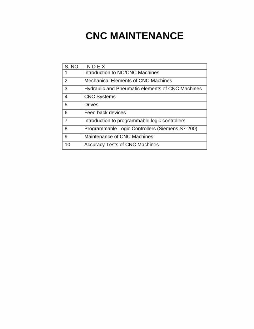
CNC MAINTENANCE
S. NO. I N D E X 1 Introduction to NC/CNC Machines 2 Mechanical Elements of CNC Machines 3 Hydraulic and Pneumatic elements of CNC Machines 4 CNC Systems 5 Drives 6 Feed back devices 7 Introduction to programmable logic controllers 8 Programmable Logic Controllers (Siemens S7-200) 9 Maintenance of CNC Machines 10 Accuracy Tests of CNC Machines
NC/CNC MACHINES, CONTROL SYSTEM FEATURES MAJOR PARTS OF CNC SYSTEM, ADVANTAGES OF
CNC MACHINES
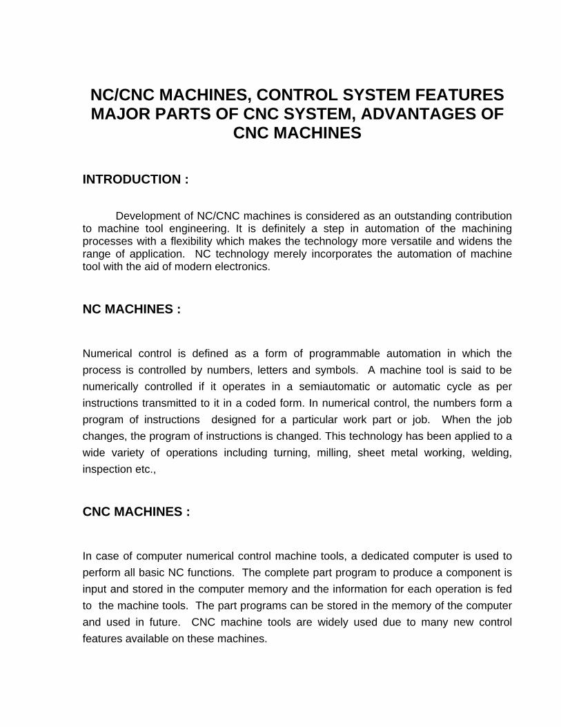
INTRODUCTION : Development of NC/CNC machines is considered as an outstanding contribution to machine tool engineering. It is definitely a step in automation of the machining processes with a flexibility which makes the technology more versatile and widens the range of application. NC technology merely incorporates the automation of machine tool with the aid of modern electronics.
NC MACHINES :
Numerical control is defined as a form of programmable automation in which the process is controlled by numbers, letters and symbols. A machine tool is said to be numerically controlled if it operates in a semiautomatic or automatic cycle as per instructions transmitted to it in a coded form. In numerical control, the numbers form a program of instructions designed for a particular work part or job. When the job changes, the program of instructions is changed. This technology has been applied to a wide variety of operations including turning, milling, sheet metal working, welding, inspection etc.,
CNC MACHINES :
In case of computer numerical control machine tools, a dedicated computer is used to perform all basic NC functions. The complete part program to produce a component is input and stored in the computer memory and the information for each operation is fed to the machine tools. The part programs can be stored in the memory of the computer and used in future. CNC machine tools are widely used due to many new control features available on these machines.
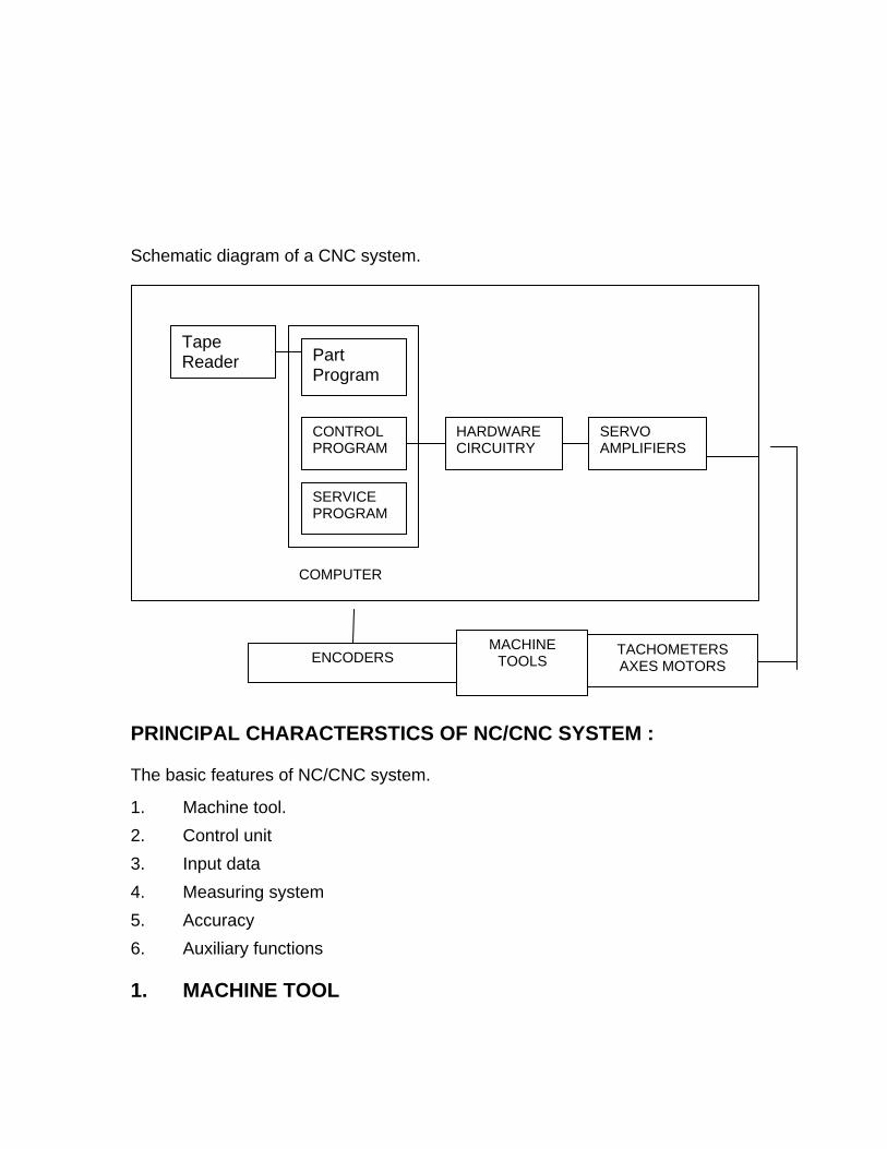
Schematic diagram of a CNC system.
Tape Reader Part
Program
CONTROL PROGRAM
HARDWARE CIRCUITRY
SERVO AMPLIFIERS
SERVICE PROGRAM
COMPUTER
ENCODERS MACHINE
TOOLS TACHOMETERS AXES MOTORS
PRINCIPAL CHARACTERSTICS OF NC/CNC SYSTEM : The basic features of NC/CNC system.
1. Machine tool. 2. Control unit 3. Input data 4. Measuring system 5. Accuracy 6. Auxiliary functions 1. MACHINE TOOL
The major information is the type of machine (i.e. Vertical milling machine, Horizontal milling machine etc., ) and it must be followed by additional information such as. Number of machine axes Maximum allowable travelling dimensions of each axis. Maximum spindle power Range of speeds and feeds. Constant possibilities. Static Dynamic characteistics. 2. MACHINE CONTROL UNIT Basic information includes Number of motion control channels.
Type of control structure - Analog or Digital
Type of system - Point to point, Straight line, Continuous path, contouring.
Type of interpolation - Linear, Circular, Parabolic or Combination of these.
Maximum feed rate. 3. INPUT DATA Input data includes information about the control medium, information about
computer programs should also be given. Knowledge of the following must be provided.
Control medium: perforated tape, magnatic tape, etc.
Capability of manual handling of input data
Type of dimensional programming: Absolute, Incremental or both etc.,
Number of digits in each dimensional word etc.,
Input resolution
Information about programming methods and languages
List of Preparatory (G) & Miscellaneous (M) functions
Tool changing codes
Speed and Feed range codes
Tape reader type - Mechanical or photo electric etc.,
Tape code - ISO, EIA

Recommended order of words in a block & number of digits in each word
Use of algebric signs.
4. MEASURING SYSTEM
Features of the measuring system
Method of coupling the measuring element
Absolute or Incremental measurement
Type of element - Encoder, Resolver, Inductosyn etc.,
5. ACCURACY Positioning accuracy : Difference between required and actual position of machine slide.
Contour accuracy : Gain in a contouring system
Repeatability : Difference between accuracy on repeating the Operation.
6. AUXILIARY INFORMATION Floating Zero, Zero offsets, Fixed Zero
Backlash take-up circuit.
Compensation capabilities for length and radius of tool
Provision for mirror images, scaling etc.,
NC/CNC SYSTEM CLASSIFICATION :
a) Based on feed back control
b) Based on control system features.
a) Classification based on Feed back control system Based on feed back control, the NC/CNC systems are classified as Open loop & Closed loop control systems. i) Open loop control system
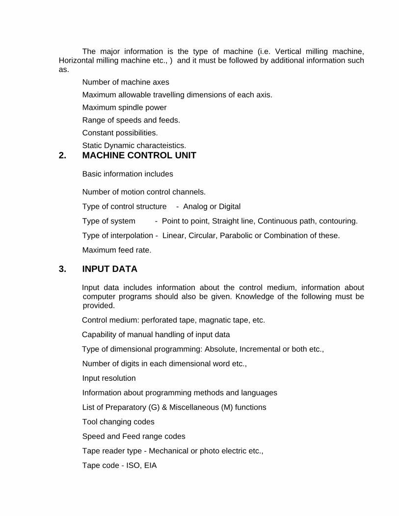
Machine tool control in which there is no provision to compare the actual positon of the cutting tool or work piece with the input command value are called open loop systems. In open loop system the actual displacement of the slide may vary with change in external condition and due to wear of the components of the drive mechanism. Open loop systems are less expensive than closed loop systems due to the absence of monitoring devices and their maintenance is not complicated. Block diagram of an open loop system :
MACHINE CONTROL UNIT
MOTOR MACHINE SLIDE
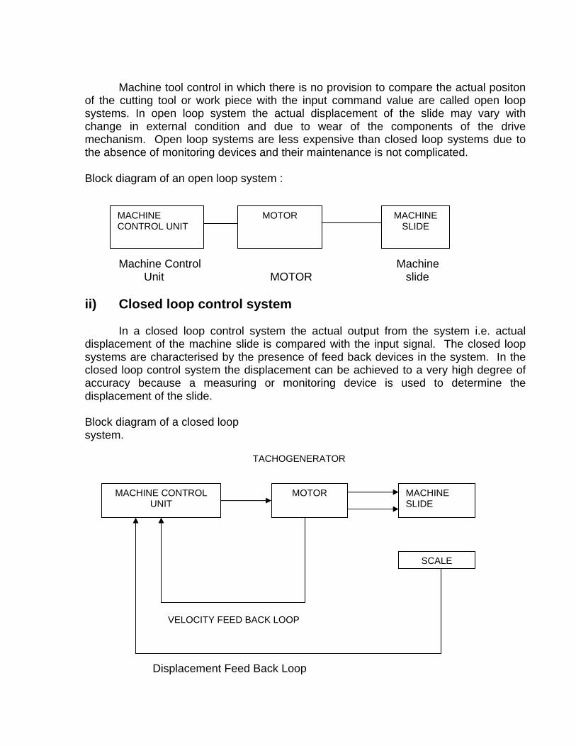
Machine Control Machine Unit MOTOR slide ii) Closed loop control system In a closed loop control system the actual output from the system i.e. actual displacement of the machine slide is compared with the input signal. The closed loop systems are characterised by the presence of feed back devices in the system. In the closed loop control system the displacement can be achieved to a very high degree of accuracy because a measuring or monitoring device is used to determine the displacement of the slide. Block diagram of a closed loop system.
Displacement Feed Back Loop
MACHINE CONTROL UNIT
MOTOR MACHINE SLIDE
SCALE
TACHOGENERATOR
VELOCITY FEED BACK LOOP
b) CLASSIFICATION BASED ON CONTROL SYSTEM FEATURE Based on control system feature, the NC/CNC control systems are classified as . 1) Point to point control system 2) Straight line control system 3) Continuous path / contouring control system 1) Point to point control system In point to point control system, control requires to position the machine tool slides to the pre determined coordinate point. The tool moves to the predetermined position in the shortest possible time. This control system is suitable for the drilling, boring, tapping, punching and jig boring machines. 2) Straight line control system In straight line control system, in addition to point to point control, control to machine along a straight line at controlled feed rate is provided. This is suitable for straight line milling and turning operations. 3) Continuous path / contouring control system In contouring control, several axes can be simultaneously controlled. This enables machining of various contours / profiles. MAIN ELEMENTS OF CNC MACHINES To enable electronic automation with high rate of metal removal at optimum cutting conditions, maintaining high repetitive accuracies with utmost safety to the operator and the machine, CNC machines are specially designed. The main elements of CNC machines are :
i) Machine structure ii) Guide ways iii) Spindle bearings & mounting iv) Drive units v) Mech. Power transmission vi) Position feed back elements / systems vii) Additional accessories / equipment viii) Control software ix) Chip removal system x) Safety features i) Machine structure Structures are designed to withstand static, dynamic & thermal loads providing high stiffness, rigidity & damping properties. The material used is generally mechanite
cast iron / special casting with nickel & copper elements. Welded structures also in wide usage. ii) Guide ways Guide ways are designed to reduce/ eliminate friction, providing high, precision. This is achieved through aerostatic / hydrostatic guide ways, tycoway bearing. LM guide ways and the surfaces of counter guides coated with PTFE (Poly Tetra Ethylene) etc. iii) Spindle bearings & mounting Designed for high accuracies, stiffness, stability and to minimise torsional strain providing high rpm range. iv) Drive units AC/ DC servo motors and drive systems with infinitely variable speed and high response are used.
v) Mech. Power transmission Specially designed with minimum gear transmission and isolated to reduce thermal effects. etc. Sliding friction is converted to rolling friction by re-circulating ball screws with nuts arrangement etc. providing precision movement eliminating backlash, stick-slip etc. vi) Position feedback elements / systems Linear / rotary transducers, tacho generators etc., are provided for precise control of the movements of the machine slides etc., vii) Additional accessories / equipment Level of automation depends on the accessories/equipment and further enhance the optimum utilization of the CNC machine. The equipments such as Automatic tool changer, Automatic attachment changers, Work changers, Electronic probes, Tool monitoring system etc. viii) Control software Automation level & optimum utilization of the CNC machine depends on features provided in the control system. Such as Simultaneous control of no. of axes. Compensation functions, Mirror image, Scaling etc.
ix) Chip removal system Efficient chip removal system eliminates thermal effects & thus improves the quality of cutting and the job being machined. x) Safety Suitable covers for guide-ways etc., and electronic interlocks for the safety of the operating personnel and machine are provided. ADVANTAGES OF CNC MACHINE Flexibility Small batch size Reduced work-in-process inventory Reduced tooling Reduced lead time Reliable operation Repetitive quality Reduced scrap rate Optimum machine utilization Increased operational safety Reduction in manufacturing costs Short response time to implement design changes.
COORDINATE SYSTEM
Coordinate is the relative positioin of a point with reference to the datum point generally denoted by zero point and there are mainly two types of coordinate systems that may be employed by a control system to position the tool or cutter in relation to the work piece.
1. Cartesian Coordinate system
2. Polar Coordinate system
Each have their application and may be used independently or mixed according to the features present with in the component.
1. CARTESIAN CO-ORDINATE SYSTEM
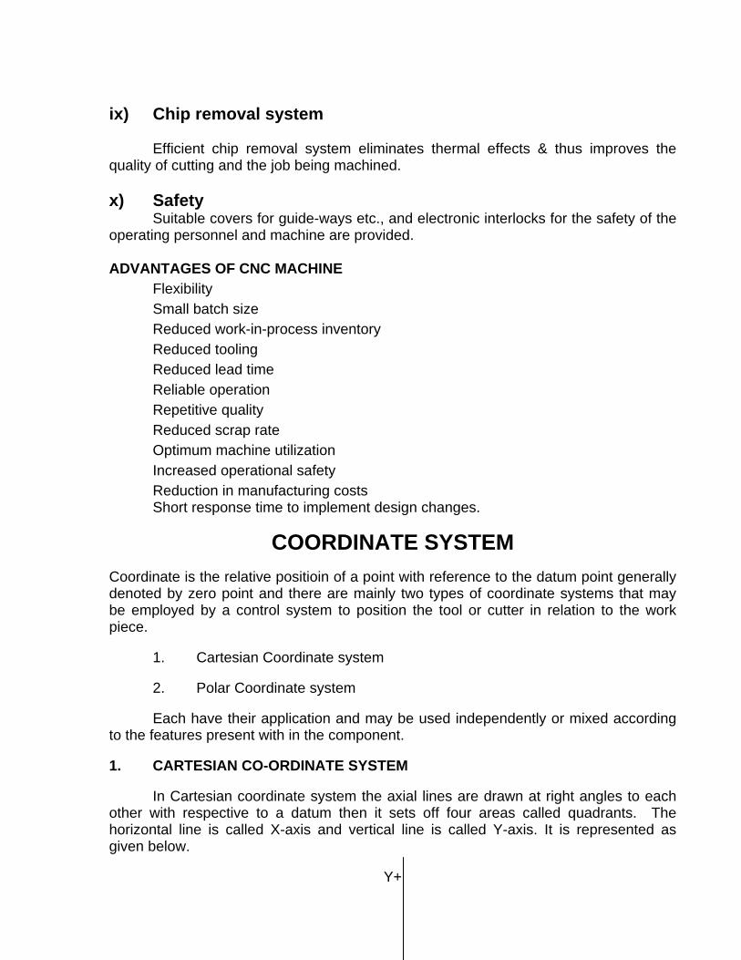
In Cartesian coordinate system the axial lines are drawn at right angles to each other with respective to a datum then it sets off four areas called quadrants. The horizontal line is called X-axis and vertical line is called Y-axis. It is represented as given below.
Y+

(-,+) QUADRANT I (+,+) QUADRANT II
X- X+
(-,-) QUADRANT III (+,-) QUADRANT IV
Y-
1. If the point lies in quadrant-I, both X and Y coordinate are positive sign.
2. If the point lies in quadrant-II, X is negative sign and Y is positive sign.
3. If the point lies in quadrant III, both X and Y coordinates are negative sign.
4. If the point lies in quadrant IV, X is positive and Y is negative sign.
In Cartesian coordinate system point is defined by its distance from its perpendicular axis and sign.
+Q Y+ 30
20
10
X- 0 X+
40 30 20 10 10 20 30 40
10
20
+R 30 +S
Y-

POINT X CO-ORDINATE Y CO-ORDINATE
P +10 +20
Q -40 +30
R -30 -30
S +30 -20
POLAR COORDINATE SYSTEM
In Polar coordinate system the point is represented by a radius (distance from zero point) and angle (Angle from horizontal axis).
Y+
200
P
X+
300
R
Y- POINT RADIUS ANGLE P 30 45 deg. Q 50 110 deg R 40 210 deg.
In CNC Programming, control systems will accept the both coordinate system but In CNC Programming, control systems will accept the both coordinate system but depends on the component features some times Cartesian system is more convenient and in some cases polar is more convenient.
In this Cartesian is more convenient
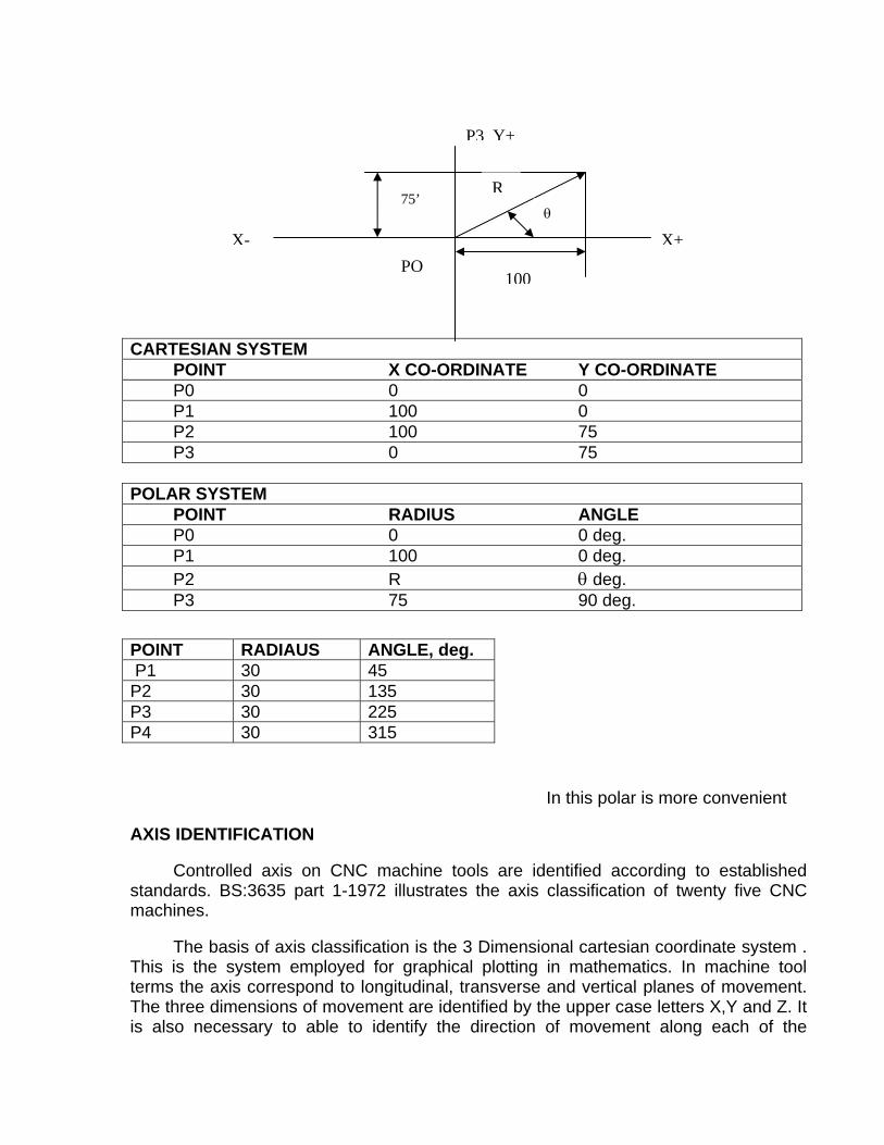
P3 Y+
CARTESIAN SYSTEM POINT X CO-ORDINATE Y CO-ORDINATE P0 0 0 P1 100 0 P2 100 75 P3 0 75 POLAR SYSTEM POINT RADIUS ANGLE P0 0 0 deg. P1 100 0 deg. P2 R θ deg. P3 75 90 deg.
POINT RADIAUS ANGLE, deg. P1 30 45 P2 30 135 P3 30 225 P4 30 315
In this polar is more convenient
AXIS IDENTIFICATION
Controlled axis on CNC machine tools are identified according to established standards. BS:3635 part 1-1972 illustrates the axis classification of twenty five CNC machines.
The basis of axis classification is the 3 Dimensional cartesian coordinate system . This is the system employed for graphical plotting in mathematics. In machine tool terms the axis correspond to longitudinal, transverse and vertical planes of movement. The three dimensions of movement are identified by the upper case letters X,Y and Z. It is also necessary to able to identify the direction of movement along each of the
R75’
θ
X- X+PO
100
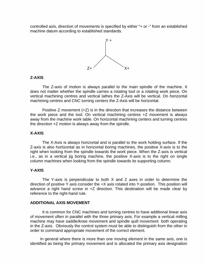
controlled axis, direction of movements is specified by either “+ or -” from an established machine datum according to established standards.
Y +
Z+ X+
Z-AXIS
The Z-axis of motion is always parallel to the main spindle of the machine. It does not matter whether the spindle carries a rotating tool or a rotating work piece. On vertical machining centres and vertical lathes the Z-Axis will be vertical. On horizontal machining centres and CNC turning centers the Z-Axis will be horizontal.
Positive Z movement (+Z) is in the direction that increases the distance between the work piece and the tool. On vertical machining centres +Z movement is always away from the machine work table. On horizontal machining centers and turning centres the direction +Z motion is always away from the spindle.
X-AXIS
The X-Axis is always horizontal and is parallel to the work holding surface. If the Z-axis is also hortizontal as in horizontal boring machines, the positive X-axis is to the right when looking from the spindle towards the work piece. When the Z-axis is vertical i.e., as in a vertical jig boring machine, the positive X-axis is to the right on single column machines when looking from the spindle towards its supporting column.
Y-AXIS
The Y-axis is perpendicular to both X and Z axes in order to determine the direction of positive Y axis consider the +X axis rotated into Y-position. This position will advance a right hand screw in +Z direction. This destination will be made clear by reference to the right-hand rule.
ADDITIONAL AXIS MOVEMENT
It is common for CNC machines and turning centres to have additional linear axis of movement often in parallel with the three primary axis. For example a vertical milling machine may have saddle/knee movement and spindle quill movement both operating in the Z-axis. Obviously the control system must be able to distinguish from the other in order to command appropriate movement of the correct element.
In general where there is more than one moving element in the same axis, one is identified as being the primary movement and is allocated the primary axis designation

X,Y or Z. Secondary movement in the same axis are then designated by the upper case letters, U,V,W corresponding to motion in the X, Y, and Z axis respectively.
It is also possible for rotary movements to be provided as part of the original machine in the form of built-in rotary tables. These rotary axis movements are identified by the upper case letters A, B and C which correspond to rotary movements about the X, Y and Z axis respectively. Clock wise rotation is designated as positive movement and counter clockwise rotation as negative movement, positive (clock wise) rotation identified by looking in the +X,+ Y and +Z direction respectively.
METHOD OF LISTING THE COORDINATES OF POINTS IN NC/CNC SYSTEM
Two types of coordinate systems are used to define and control the position of the tool in relatioin to the workpiece. Each system has its own application and the two coordinate systems may be used independent or may be mixed within a CNC part program according to the machining requirements of the component.
The coordinate data input systems used are
1) Absolute coordinate data input system
2) Incremental coordinate data input system
ABSOLUTE CO-ORDINATE DATA INPUT SYSTEM
In the absolute system the coordinate points are always referred with reference to the same datum.
The datum positions in the X-axis, Y-axis and Z-axis are defined by the user/programmer before starting the operation on the machine.
INCREMENTAL COORDINATE DATA INPUT SYSTEM
In the incremental system the coordinate of axis point are calculated with reference to previous point i.e., the point at which the cutting tool is positioned is taken as datum point for calculating the coordinate of the next point to which movement is to be made.
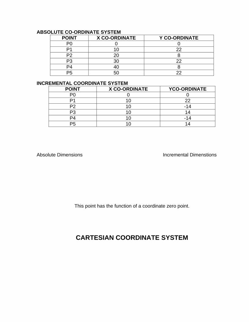
ABSOLUTE CO-ORDINATE SYSTEM POINT X CO-ORDINATE Y CO-ORDINATE
P0 0 0 P1 10 22 P2 20 8 P3 30 22 P4 40 8 P5 50 22
INCREMENTAL COORDINATE SYSTEM POINT X CO-ORDINATE YCO-ORDINATE
P0 0 0 P1 10 22 P2 10 -14 P3 10 14 P4 10 -14 P5 10 14
Absolute Dimensions Incremental Dimenstions
This point has the function of a coordinate zero point.
CARTESIAN COORDINATE SYSTEM

AXES
THE RIGHT HAND RULE
a) Relationship between Axes
b) Relationship between positive linerar and rotary axes.

AXES
MACHINING CENTRES
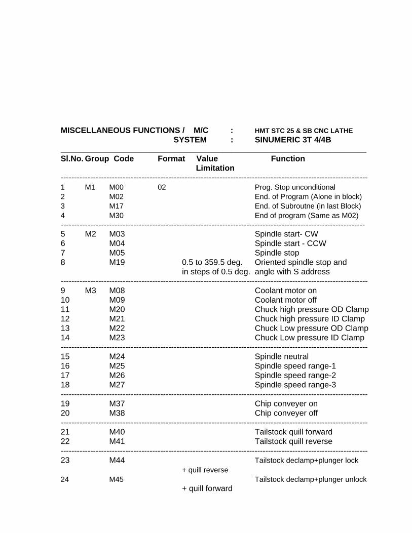
MISCELLANEOUS FUNCTIONS / M/C : HMT STC 25 & SB CNC LATHE SYSTEM : SINUMERIC 3T 4/4B ____________________________________________________________________ Sl.No. Group Code Format Value Function Limitation ------------------------------------------------------------------------------------------------------------------ 1 M1 M00 02 Prog. Stop unconditional 2 M02 End. of Program (Alone in block) 3 M17 End. of Subroutne (in last Block) 4 M30 End of program (Same as M02) ----------------------------------------------------------------------------------------------------------------- 5 M2 M03 Spindle start- CW 6 M04 Spindle start - CCW 7 M05 Spindle stop 8 M19 0.5 to 359.5 deg. Oriented spindle stop and in steps of 0.5 deg. angle with S address ------------------------------------------------------------------------------------------------------------------ 9 M3 M08 Coolant motor on 10 M09 Coolant motor off 11 M20 Chuck high pressure OD Clamp 12 M21 Chuck high pressure ID Clamp 13 M22 Chuck Low pressure OD Clamp 14 M23 Chuck Low pressure ID Clamp ------------------------------------------------------------------------------------------------------------------ 15 M24 Spindle neutral 16 M25 Spindle speed range-1 17 M26 Spindle speed range-2 18 M27 Spindle speed range-3 ------------------------------------------------------------------------------------------------------------------ 19 M37 Chip conveyer on 20 M38 Chip conveyer off ------------------------------------------------------------------------------------------------------------------ 21 M40 Tailstock quill forward 22 M41 Tailstock quill reverse ------------------------------------------------------------------------------------------------------------------ 23 M44 Tailstock declamp+plunger lock + quill reverse 24 M45 Tailstock declamp+plunger unlock + quill forward
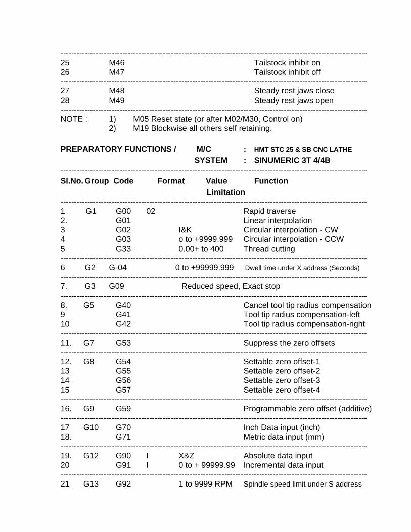
------------------------------------------------------------------------------------------------------------------ 25 M46 Tailstock inhibit on 26 M47 Tailstock inhibit off ------------------------------------------------------------------------------------------------------------------ 27 M48 Steady rest jaws close 28 M49 Steady rest jaws open ------------------------------------------------------------------------------------------------------------------ NOTE : 1) M05 Reset state (or after M02/M30, Control on)
2) M19 Blockwise all others self retaining.
PREPARATORY FUNCTIONS / M/C : HMT STC 25 & SB CNC LATHE SYSTEM : SINUMERIC 3T 4/4B ------------------------------------------------------------------------------------------------------------------ Sl.No. Group Code Format Value Function Limitation ------------------------------------------------------------------------------------------------------------------ 1 G1 G00 02 Rapid traverse 2. G01 Linear interpolation 3 G02 I&K Circular interpolation - CW 4 G03 o to +9999.999 Circular interpolation - CCW 5 G33 0.00+ to 400 Thread cutting ------------------------------------------------------------------------------------------------------------------ 6 G2 G-04 0 to +99999.999 Dwell time under X address (Seconds) ------------------------------------------------------------------------------------------------------------------ 7. G3 G09 Reduced speed, Exact stop ------------------------------------------------------------------------------------------------------------------ 8. G5 G40 Cancel tool tip radius compensation 9 G41 Tool tip radius compensation-left 10 G42 Tool tip radius compensation-right ------------------------------------------------------------------------------------------------------------------ 11. G7 G53 Suppress the zero offsets ------------------------------------------------------------------------------------------------------------------ 12. G8 G54 Settable zero offset-1 13 G55 Settable zero offset-2 14 G56 Settable zero offset-3 15 G57 Settable zero offset-4 ------------------------------------------------------------------------------------------------------------------ 16. G9 G59 Programmable zero offset (additive) ------------------------------------------------------------------------------------------------------------------ 17 G10 G70 Inch Data input (inch) 18. G71 Metric data input (mm) ------------------------------------------------------------------------------------------------------------------ 19. G12 G90 I X&Z Absolute data input 20 G91 I 0 to + 99999.99 Incremental data input ------------------------------------------------------------------------------------------------------------------ 21 G13 G92 1 to 9999 RPM Spindle speed limit under S address
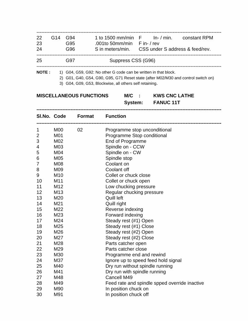
------------------------------------------------------------------------------------------------------------------ 22 G14 G94 1 to 1500 mm/min F In- / min. constant RPM 23 G95 .001to 50mm/min F in- / rev 24 G96 S in meters/min. CSS under S address & feed/rev. ------------------------------------------------------------------------------------------------------------------ 25 G97 Suppress CSS (G96) ------------------------------------------------------------------------------------------------------------------ NOTE : 1) G04, G59, G92: No other G code can be written in that block. 2) G01, G40, G54, G90, G95, G71 Reset state (after M02/M30 and control switch on) 3) G04, G09, G53, Blockwise, all others self retaining. MISCELLANEOUS FUNCTIONS M/C : KWS CNC LATHE System: FANUC 11T ------------------------------------------------------------------------------------------------------------------ Sl.No. Code Format Function ------------------------------------------------------------------------------------------------------------------ 1 M00 02 Programme stop unconditional 2 M01 Programme Stop conditional 3 M02 End of Programme 4 M03 Spindle on - CCW 5 M04 Spindle on - CW 6 M05 Spindle stop 7 M08 Coolant on 8 M09 Coolant off 9 M10 Collet or chuck close 10 M11 Collet or chuck open 11 M12 Low chucking pressure 12 M13 Regular chucking pressure 13 M20 Quill left 14 M21 Quill right 15 M22 Reverse indexing 16 M23 Forward indexing 17 M24 Steady rest (#1) Open 18 M25 Steady rest (#1) Close 19 M26 Steady rest (#2) Open 20 M27 Steady rest (#2) Close 21 M28 Parts catcher open 22 M29 Parts catcher close 23 M30 Programme end and rewind 24 M37 Ignore up to speed feed hold signal 25 M40 Dry run without spindle running 26 M41 Dry run with spindle running 27 M48 Cancell M49 28 M49 Feed rate and spindle spped override inactive 29 M90 In position chuck on 30 M91 In position chuck off
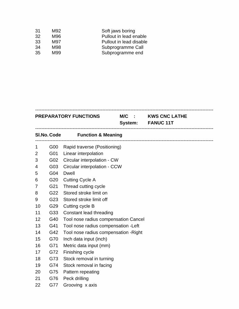
31 M92 Soft jaws boring 32 M96 Pullout in lead enable 33 M97 Pullout in lead disable 34 M98 Subprogramme Call 35 M99 Subprogramme end ------------------------------------------------------------------------------------------------------------------ PREPARATORY FUNCTIONS M/C : KWS CNC LATHE System: FANUC 11T ------------------------------------------------------------------------------------------------------------------ Sl.No. Code Function & Meaning ------------------------------------------------------------------------------------------------------------------ 1 G00 Rapid traverse (Positioning) 2 G01 Linear interpolation 3 G02 Circular interpolation - CW 4 G03 Circular interpolation - CCW 5 G04 Dwell 6 G20 Cutting Cycle A 7 G21 Thread cutting cycle 8 G22 Stored stroke limit on 9 G23 Stored stroke limit off 10 G29 Cutting cycle B 11 G33 Constant lead threading 12 G40 Tool nose radius compensation Cancel 13 G41 Tool nose radius compensation -Left 14 G42 Tool nose radius compensation -Right 15 G70 Inch data input (inch) 16 G71 Metric data input (mm) 17 G72 Finishing cycle 18 G73 Stock removal in turning 19 G74 Stock removal in facing 20 G75 Pattern repeating 21 G76 Peck drilling 22 G77 Grooving x axis
23 G78 Thread cutting cycle 24 G90 Absolute data input 25 G91 Incremental data input 26 G92 Position preset 27 G94 Feed in mm per minute/inch per minute 28 G95 Feed in mm / inch per revolutions 29 G96 Constant surface feed on 30 G97 Constant surface feed off
MECHANICAL ELEMENTS OF
CNC MACHINES
BASIC MECHANICAL ELEMENTS OF CNC MACHINE
INTRODUCTION:
Automation of production process brought forth by Introduction of Computerised Numerical Control technology has demanded considerable improvement in the performance of machine tool. Hence a significant change has been noticed in the constructional features and in use of various mechanical elements in the machine. Some of the special elements used such as : A. Machine Structure. b. Guide ways. c. Feed Drives. d. Spindle and spindle bearings.
MACHINE STRUCTURE
The machine structure is the load carrying and supporting member of the machine tool. All the motors, drive mechanisms and other functional assemblies of machine tool are aligned to each other and rigidly fixed to the machine structure. The machine structure is subjected to static and dynamic forces. It is essential that the structure does not deform or vibrate beyond the permissible limits under the action of these forces. All the parts of the machine must remain in correct relative relationship to maintain the geometric accuracy regardless of magnitude and direction of these forces. The machine structure configuration is also influenced by the requirements of the manufacture, assembly and operation. The basic design factors involved in the design of a machine structure are: STATIC LOAD
The static load of a machine tool results from the weights of slides and the job, and the forces due to cutting. To keep deformation of the structure within the permissible limits due to static loading, the structure should have adequate stiffness and proper structural configuration. Generally there are two basic configurations used in machine tools as shown in Fig:1
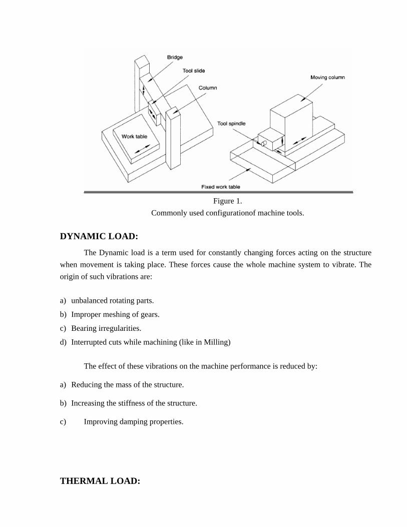
Figure 1.
Commonly used configurationof machine tools.
DYNAMIC LOAD:
The Dynamic load is a term used for constantly changing forces acting on the structure when movement is taking place. These forces cause the whole machine system to vibrate. The origin of such vibrations are: a) unbalanced rotating parts.
b) Improper meshing of gears.
c) Bearing irregularities.
d) Interrupted cuts while machining (like in Milling)
The effect of these vibrations on the machine performance is reduced by:
a) Reducing the mass of the structure.
b) Increasing the stiffness of the structure.
c) Improving damping properties. THERMAL LOAD:
In a machine tool there are a number of local heat sources, which cause the thermal gradients within the machine. some of these sources are :-
a) electric motor
b) Friction in mechanical drives and gear boxes.
c) Friction bearings and guide ways.
d) Machining process.
e) Temperature of surrounding objects. These heat sources cause localised deformation resulting in considerable inaccuracies in machine performance. Following steps are generally taken to reduce the thermal deformation:
a) External mounting of drives i.e. motors and gearboxes.
b) Dissipation of frictional heat from bearings and guide ways by proper lubrication system.
c) Dissipation of heat generated from the machining process by proper coolant system and swarf removal system.
d) Thermo - symmetric design of the structure. GUIDEWAYS:
Guide ways are mainly used in machine tools to
1) Control the direction or line of action of the carriage or the table on which a tool or a work is held.
2) To absorb all the static and dynamic forces.
The shape and size of the work produced on a machine tool also depends on geometric and kinematic accuracies of the guide ways.
When the machining is taking place, the rate of transitional movement (feed rate) can be as low as 20 mm/min. during positioning. The feed rate can be as high as 30m/min. for fine machined surfaces and for accurate positioning, the movement must be smooth and continuous, and free from any jerky movement.
The following points should be considered while designing the guide ways. 1. Rigidity. 2. Damping capability.
3. Geometric and kinematic accuracy. 4. Velocity of the slide. 5. Friction characteristics. 6. Wear resistance. 7. Provision for adjustment of play. 8. Position in relation to work area.
9. Protection against swarf and damage.
TYPES OF GUIDE WAYS
Guide ways are mainly two types as per their contacting characteristics.
1. Friction Guide ways: The relation between moving part (Guide) and stationary part (Guide way) contacting directly each other.
2. Anti Friction Linear Motion Guide ways: Here the contact between guide and guide way may be separated by the third element i.e. Ball, Roller or hydraulic oil film in case of Hydro dynamic or hydrostatic guide way systems.
FRICTION GUIDE WAYS
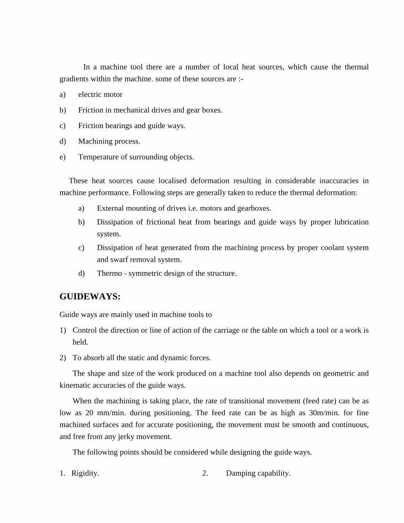
Friction guide ways are almost suitable for conventional machine tools, as their manufacturing cost is low and good damping properties. Friction guide ways are operate under conditions of sliding friction and do not have a constant co efficient of friction. The relation diagram of co efficient of friction and the slide velocity as shown in Fig No:2
Figure 2
Relation of coefficient of friction and slide velocity for friction guideways The friction co efficient is very high at the starting and as the speed of the slide increases it rapidly falls and further remains almost constant. Therefore to start the movement, the force to overcome friction has to be correspondingly high. This force results in the drive mechanisms, such as a screw being elastically deformed. As the speed increases the friction decreases and a
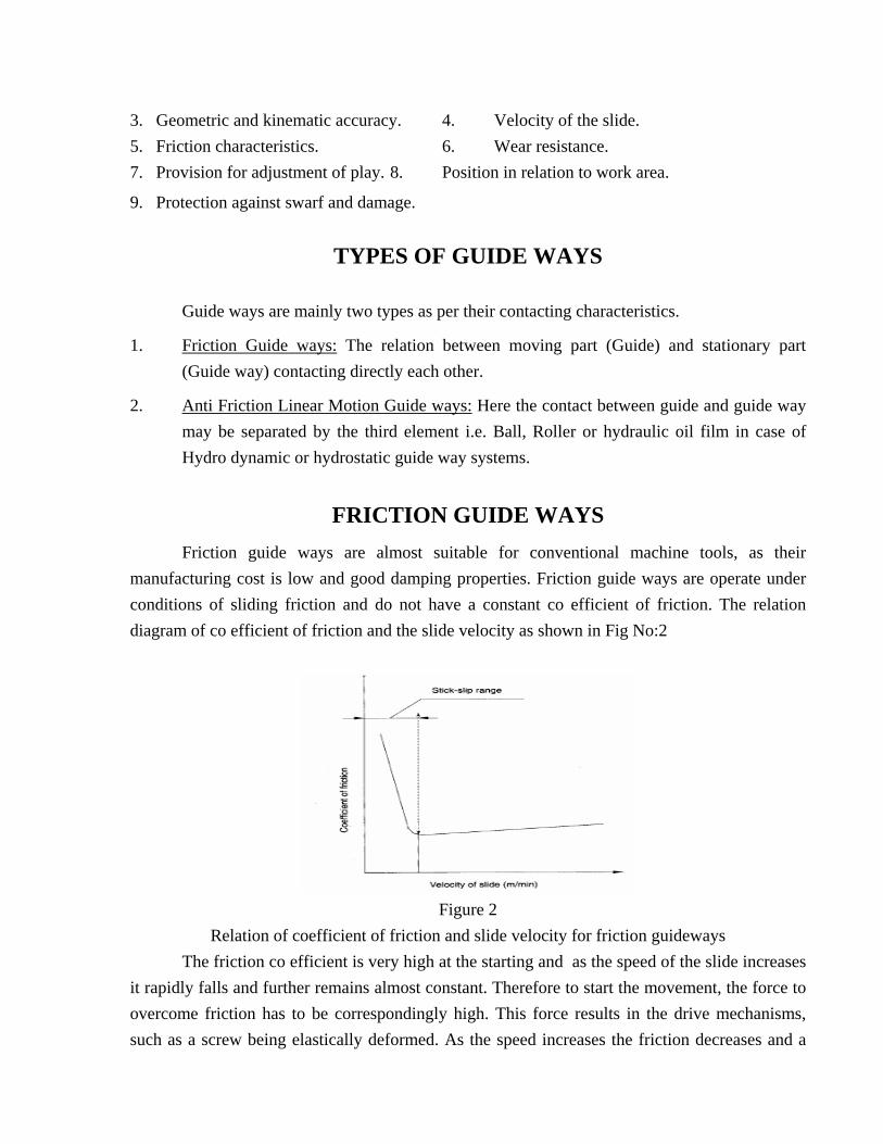
greater amount of movement than that intended of the slide results. There is a possibility of this cycle of events repeating, resulting in errors in positioning and jerky motion. This phenomenon is called as stick slip phenomenon. To reduce the possibility of stick slip there should be a minimum but a constant friction between the surfaces in contact. This is achieved in friction guide ways using strips of material such as PTFE or TURCITE lining at the guide way interface. Coating of PTFE or TURCITE or any other anti friction material can be carried out on VEE, FLAT as well as on DOVETAIL guide ways shown in Fig No.3.
Fig No.3. Cross section of coated guideways
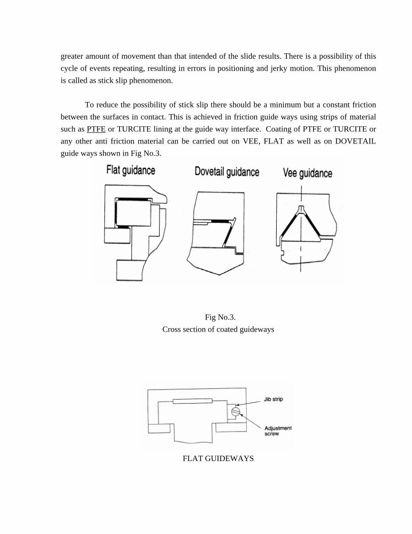
FLAT GUIDEWAYS
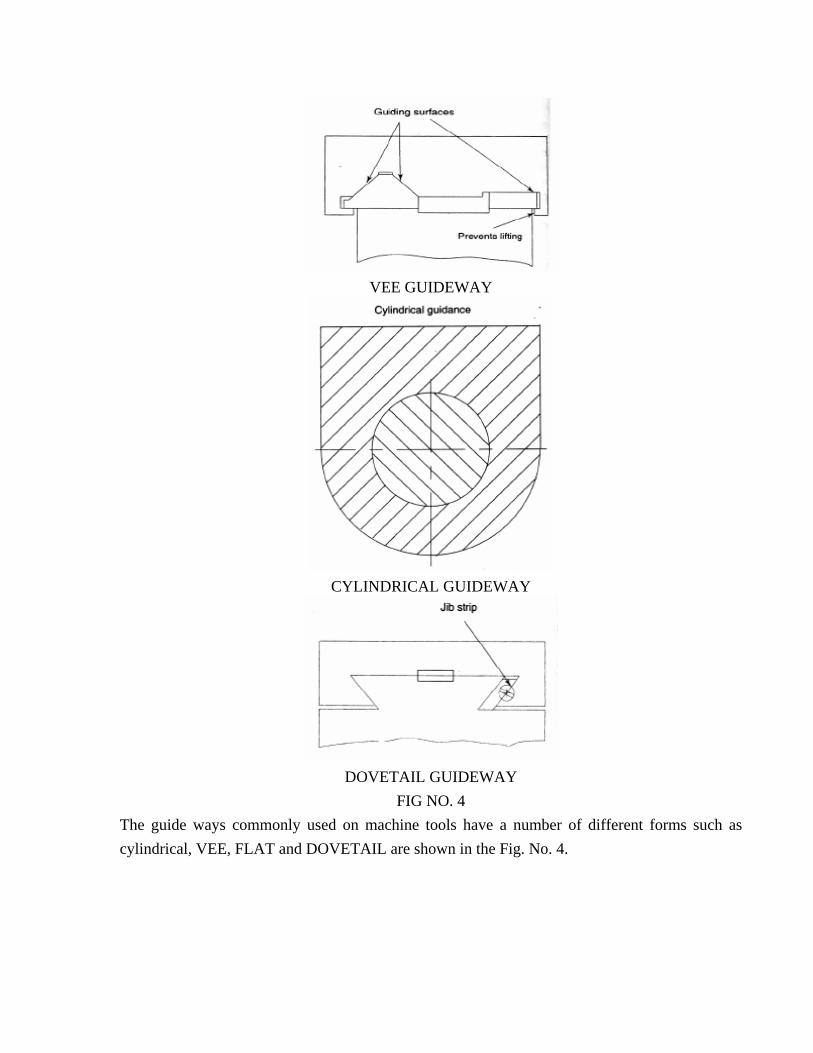
VEE GUIDEWAY
CYLINDRICAL GUIDEWAY
DOVETAIL GUIDEWAY
FIG NO. 4 The guide ways commonly used on machine tools have a number of different forms such as cylindrical, VEE, FLAT and DOVETAIL are shown in the Fig. No. 4.
ANTI FRICTION LINEAR MOTION GUIDE WAYS
Metal to Metal contact has a relatively High co efficient of Friction and results in tough wear, heat generation and an increase in the power required to move the slide. To eliminate this limitation anti friction linear motion guide ways are used on the CNC machine tools to: 1) Reduce the amount of wear
2) Improve the smoothness of the movement.
3) Reduce the friction
4) Reduce the heat generation Anti friction guide ways use rolling elements in between the moving and the stationary
elements of the machine. They provide the following advantages when compared with friction guides:
1) Low frictional resistance
2) No stick-slip
3) Ease of assembly
4) Commercially available in ready to fit condition
5) High load carrying capacity
6) Heavier pre loading possibility
7) High traverse speeds. The main disadvantage of these guide ways compared to friction guide ways is its lower
damping capacity.
The manufacturers of machine tools use several options for anti friction linear motion guide ways like:
1) Re circulating ball bushing
2) Linear bearings with balls and rollers such as re circulating LM guides
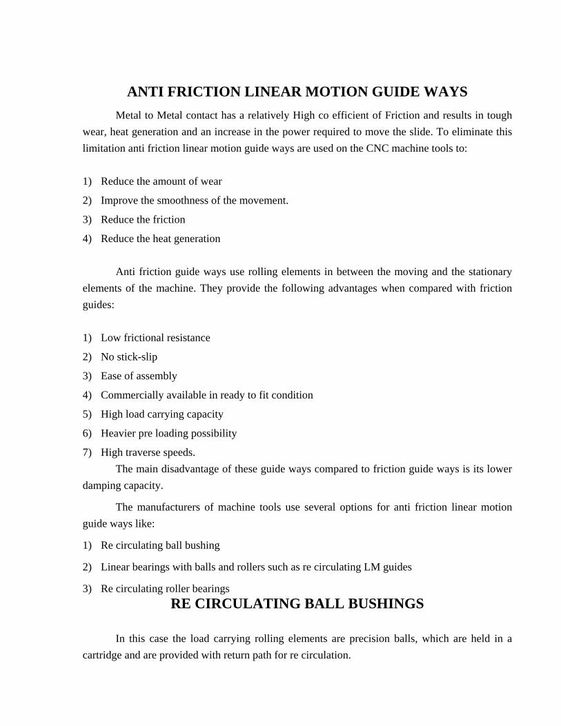
3) Re circulating roller bearings RE CIRCULATING BALL BUSHINGS
In this case the load carrying rolling elements are precision balls, which are held in a cartridge and are provided with return path for re circulation.
Re circulating ball bushes are two types: open type and close type.
Ball bushings offer very low friction and can be used without clearance unlike in the case of conventional sliding type guide way, which needs working clearance between sliding members for proper lubrication and functioning. The constructional features of ball bushings are shown in the Fig No.5.
FIG NO.5 FIG. NO.5 Closed type ball bushing Open type ball bushing
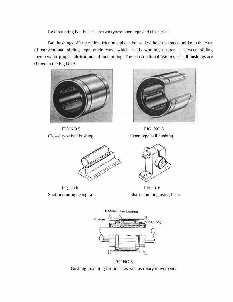
Fig. no.6 Fig no. 6 Shaft mounting using rail Shaft mounting using black
FIG NO.6
Bushing mounting for linear as well as rotary movements
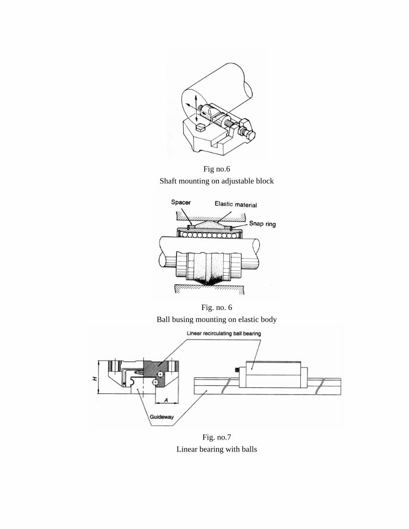
Fig no.6
Shaft mounting on adjustable block
Fig. no. 6
Ball busing mounting on elastic body
Fig. no.7
Linear bearing with balls
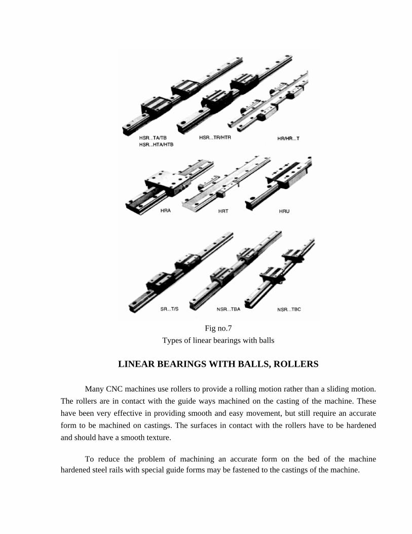
Fig no.7
Types of linear bearings with balls
LINEAR BEARINGS WITH BALLS, ROLLERS Many CNC machines use rollers to provide a rolling motion rather than a sliding motion. The rollers are in contact with the guide ways machined on the casting of the machine. These have been very effective in providing smooth and easy movement, but still require an accurate form to be machined on castings. The surfaces in contact with the rollers have to be hardened and should have a smooth texture.
To reduce the problem of machining an accurate form on the bed of the machine hardened steel rails with special guide forms may be fastened to the castings of the machine.
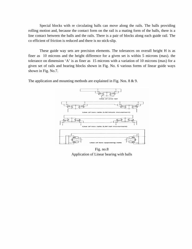
Special blocks with re circulating balls can move along the rails. The balls providing rolling motion and, because the contact form on the rail is a mating form of the balls, there is a line contact between the balls and the rails. There is a pair of blocks along each guide rail. The co efficient of friction is reduced and there is no stick-slip. These guide way sets are precision elements. The tolerances on overall height H is as finer as 10 microns and the height difference for a given set is within 5 microns (max). the tolerance on dimension ‘A’ is as finer as 15 microns with a variation of 10 microns (max) for a given set of rails and bearing blocks shown in Fig. No. 6 various forms of linear guide ways shown in Fig. No.7. The application and mounting methods are explained in Fig. Nos. 8 & 9.
Fig. no.8
Application of Linear bearing with balls
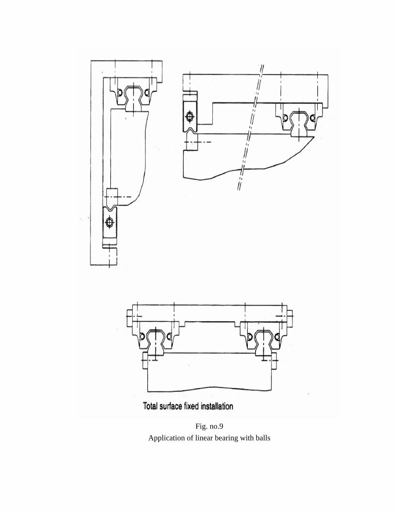
Fig. no.9
Application of linear bearing with balls
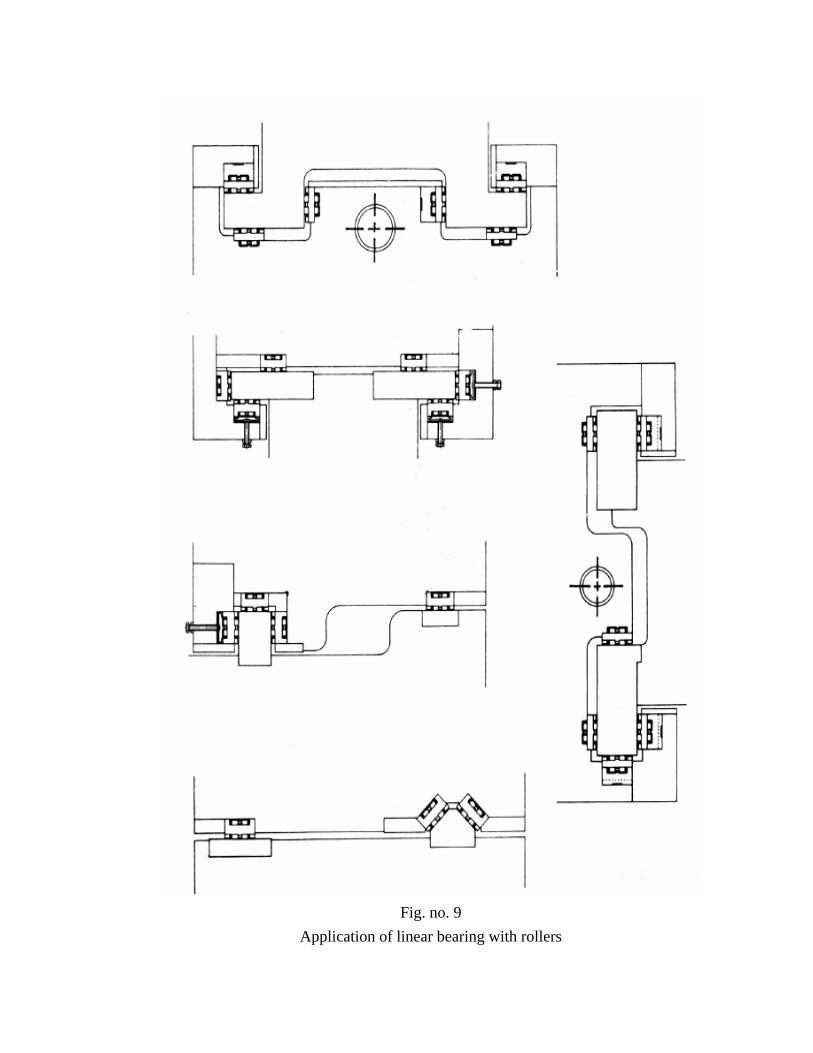
Fig. no. 9
Application of linear bearing with rollers
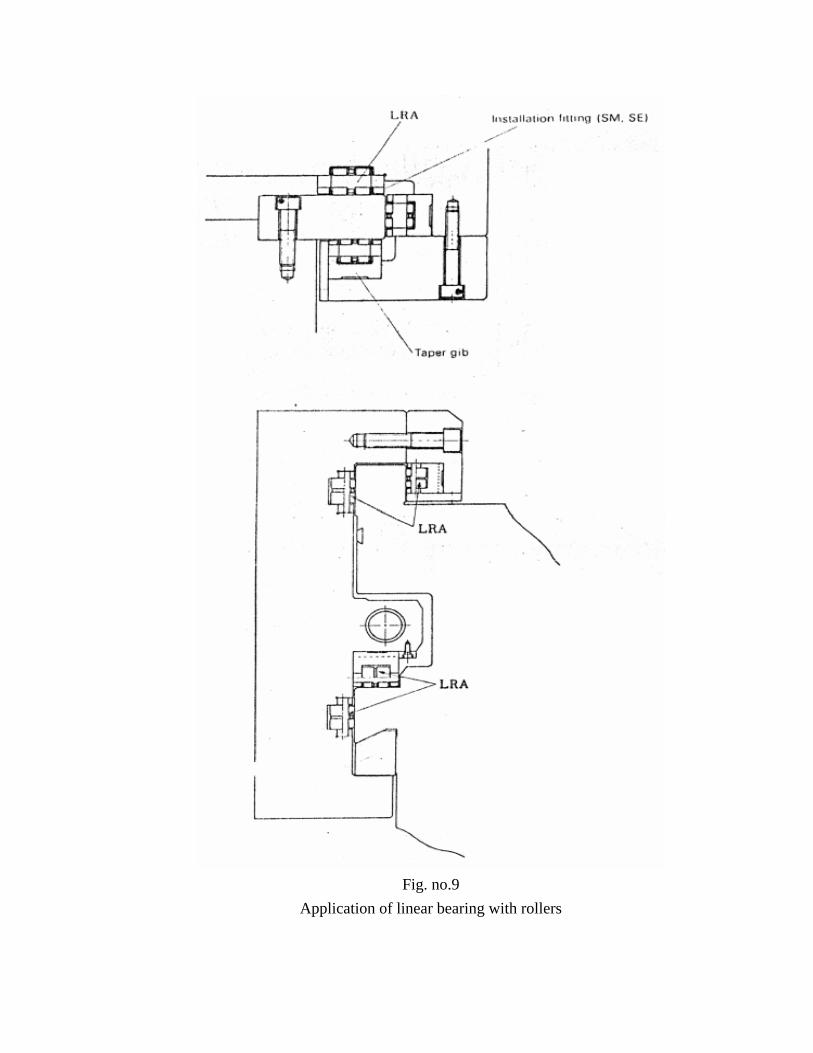
Fig. no.9
Application of linear bearing with rollers
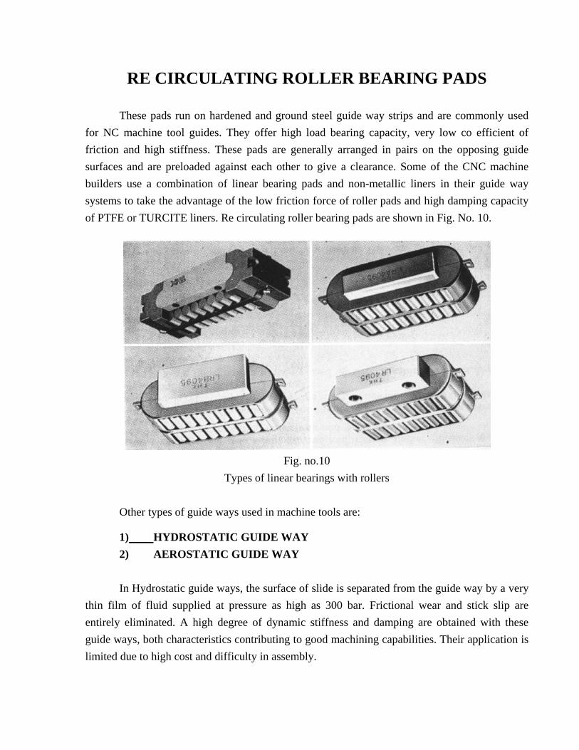
RE CIRCULATING ROLLER BEARING PADS These pads run on hardened and ground steel guide way strips and are commonly used for NC machine tool guides. They offer high load bearing capacity, very low co efficient of friction and high stiffness. These pads are generally arranged in pairs on the opposing guide surfaces and are preloaded against each other to give a clearance. Some of the CNC machine builders use a combination of linear bearing pads and non-metallic liners in their guide way systems to take the advantage of the low friction force of roller pads and high damping capacity of PTFE or TURCITE liners. Re circulating roller bearing pads are shown in Fig. No. 10.
Fig. no.10
Types of linear bearings with rollers
Other types of guide ways used in machine tools are:
1) HYDROSTATIC GUIDE WAY 2) AEROSTATIC GUIDE WAY In Hydrostatic guide ways, the surface of slide is separated from the guide way by a very
thin film of fluid supplied at pressure as high as 300 bar. Frictional wear and stick slip are entirely eliminated. A high degree of dynamic stiffness and damping are obtained with these guide ways, both characteristics contributing to good machining capabilities. Their application is limited due to high cost and difficulty in assembly.
In Aerostatic guide ways, the slide is raised on a cushion of compressed air which entirely separates the slide and the guide way surfaces. The major limitation of this type guide ways is a low stiffness, which limits its use for positioning application only. e.g. CMM and other measuring instruments.
The selection of guide ways for a particular application basically depends upon the
requirements of the load carrying capacity, damping property and the traverse speed.
FEED DRIVES
On a CNC machine the function of feed drive is to provide the motion to the slide as per motion commands. Since the degree of accuracy requirements are high, the feed drive should have high efficiency and high response. The feed drive consists of:
1) Servo motor 2) Mechanical transmission system.
SERVO MOTOR
Commonly used feed drive motors for CNC machines are DC servomotors and AC
servomotors
Initially, dc servomotors and drives were used most commonly on all CNC machines. These servomotors provide excellent speed regulation, high torque and high efficiency. With development of AC servos at a cost comparable with DC servos, AC servos are becoming more popular for machine tool applications. This is because AC servo motors provide constant torque over their entire speed range, requires less maintenance due to brush less
operation, have better response, better dynamic stiffness and higher reliability, compared to DC servo motors.
MECHANICAL TRANSMISSION SYSTEM The mechanical transmission system of feed drive comprises of all the components which
are in the force and motion transmission paths from drive motor to the slide they are:
1) Elements to convert the rotary motion to a linear motion ( re circulating ball screw-nut system or rack and pinion)
2) Torque transmission elements ( gear box or timing belt and coupling)
While designing mechanical transmission system the following points must be considered:
1) High natural frequency 2) High stiff ness. 3) Sufficient damping. 4) Low friction. 5) Backlash free operation.
ELEMENTS USED TO CONVERT THE ROTARY MOTION TO
A LINEAR MOTION
Various types of actuating mechanisms are used in CNC machines to convert the rotational movement to a translational movement. The efficiency and responsiveness of the actuating mechanism have the greatest influence on the accuracy of the work produced. The actuating mechanisms used for the slides of CNC machines are screw. ex. NUT, and rack and pinion.
SCREW AND NUT
The screw and nut systems effective for medium traverses, with longer traverses the screw sags under its own weight. Longer the screw length lower is the upper limit of traverse rates due to reduction in the critical speed. Conventional ‘VEE’ , ‘ACME’ or square thread forms are not suitable for CNC machines because the sliding action of contacting surfaces of the thread on screw and nut results in rapid wear and the friction is high. The efficiency of these screws are only of the order of 40%. There are two types of screw and nut used on the CNC machine tools which provide low wear, accuracy over a long life, reduced friction, high efficiency and better reliability. These are re circulating ball screws and roller screws.
operation, have better response, better dynamic stiffness and higher reliability, compared to DC servo motors.
RE CIRCULATING BALL SCREWS
In ball screws, the sliding friction encountered in conventional screws and nuts is replaced by rolling friction in a manner analogous to replacing journal bearings with ball bearings. The following are the advantages of the ball screws:
1) Low frictional resistance. 2) Low drive power requirement. 3) Lesser temperature rise. 4) Less wear hence longer life. 5) No stick slip effect. 6) High traverse speed. 7) High efficiency.
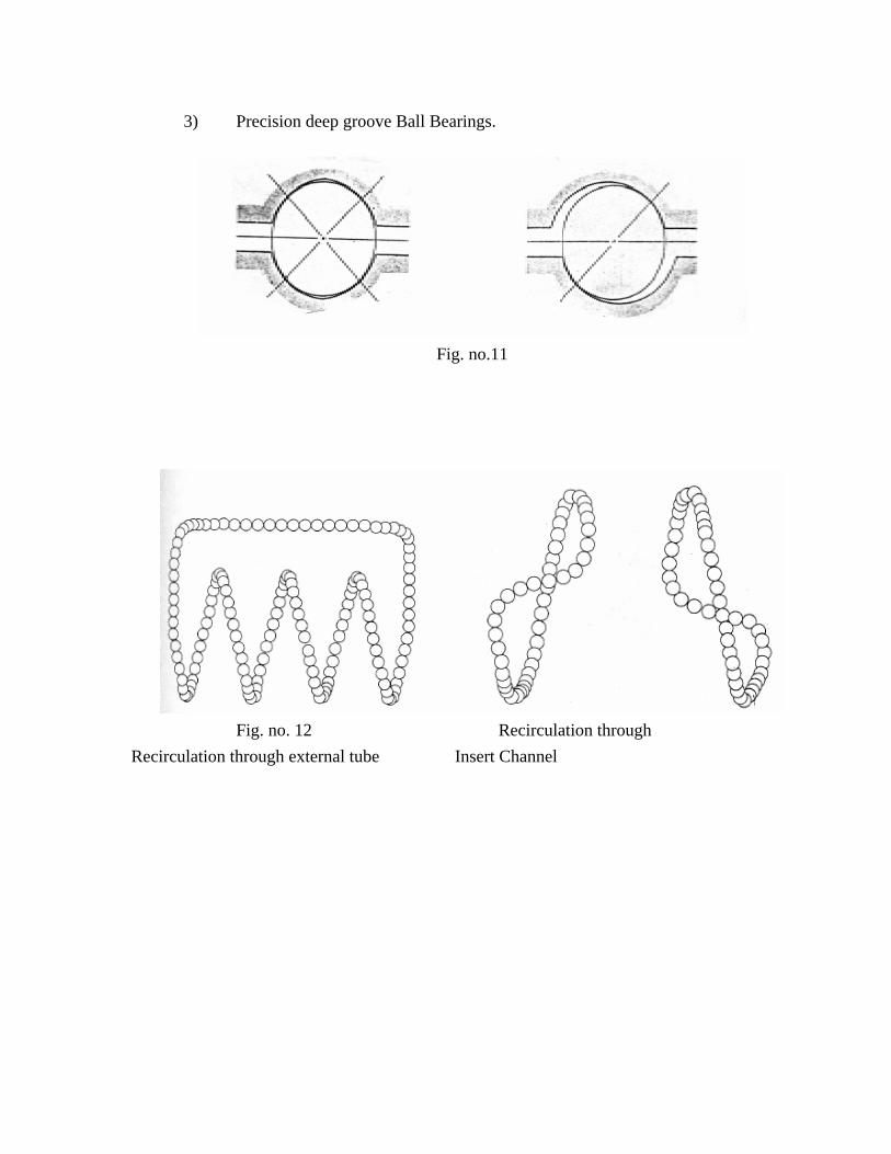
There are two kinds of thread forms used on the ball screws:
1) Circular arc and
2) Gothic arc.
These are shown in the Fig No.11. The balls rotate between the screw and the nut and at some point they are returned to the start of the thread in the nut. Two types of re circulating arrangement are shown in Fig. No.12.
The efficiency of re circulating ball screw is of the order 90% and is obtained by the balls providing a rolling motion between the screw and nut. The mounting arrangement of ball screw depends on the required speed, length and size of the ball screw.
Fig. No. 13,14 & 15 shows various methods of mounting a ball screw in a machine tools.
The position of the ball screw should be near the line of resultant force arising from cutting, frictional, inertial forces.
In ball screw system greater attention should be given to the selection of end bearings to
minimise the positioning inaccuracies. The function of bearings for ball screw is to locate the screw radially and resist the axial thrust force. These bearings should have high load capacity, high axial stiffness and low axial runouts (of the order of 2 microns) commonly used ball screw end bearings are:
1) Set of Angular contact ball bearings. 2) Set of thrust and Radial Roller Bearings.
3) Precision deep groove Ball Bearings.
Fig. no.11
Fig. no. 12 Recirculation through Recirculation through external tube Insert Channel
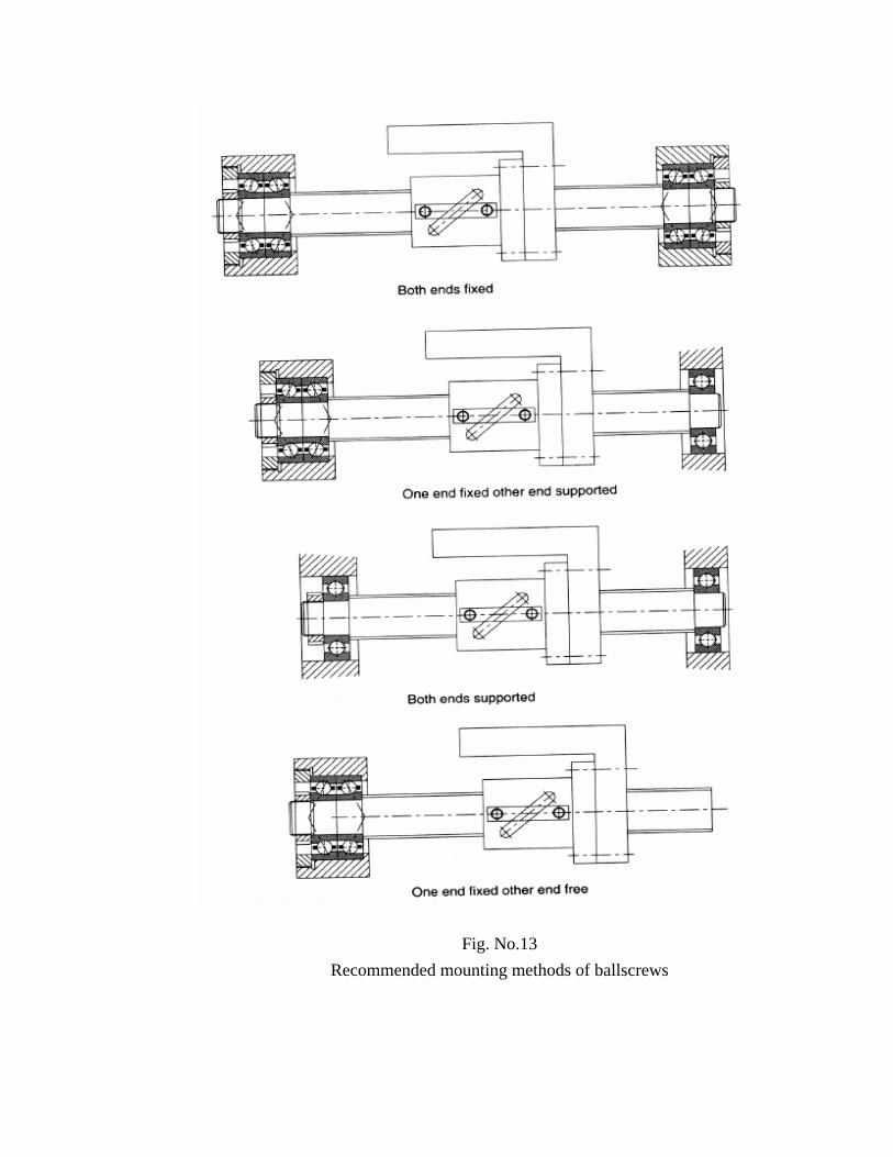
Fig. No.13 Recommended mounting methods of ballscrews
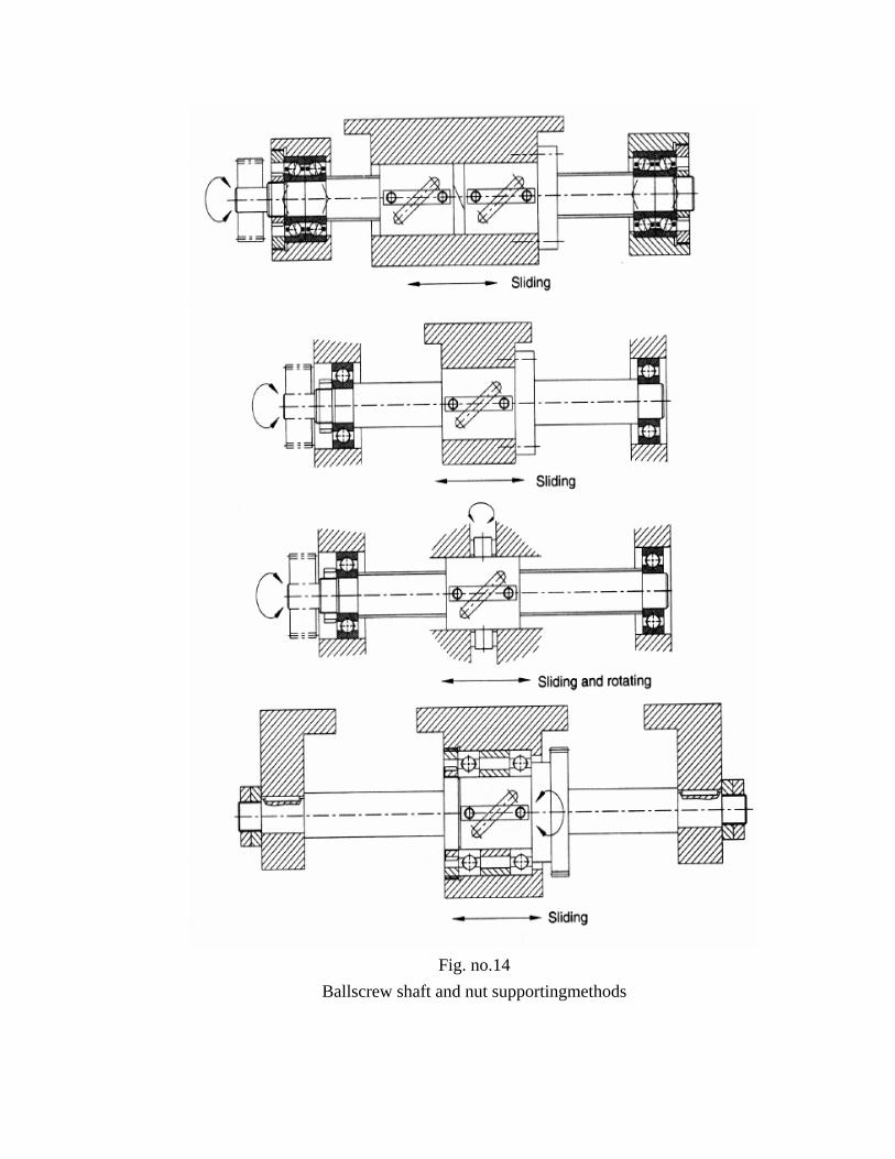
Fig. no.14
Ballscrew shaft and nut supportingmethods
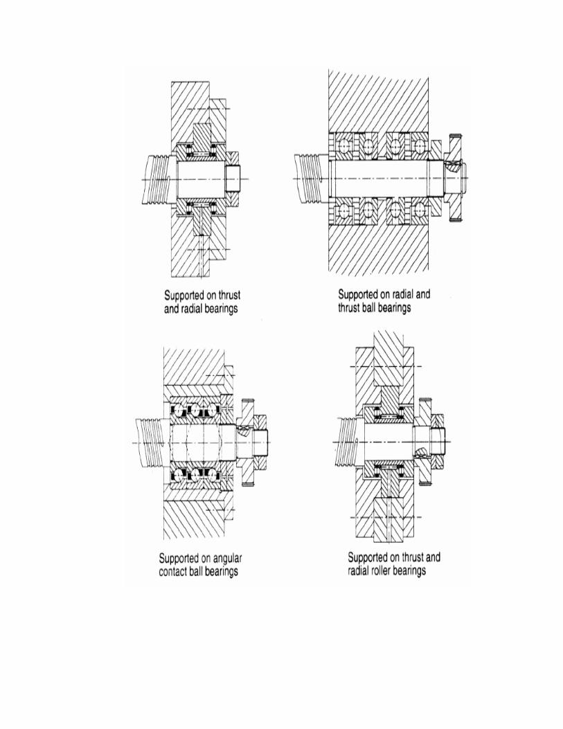
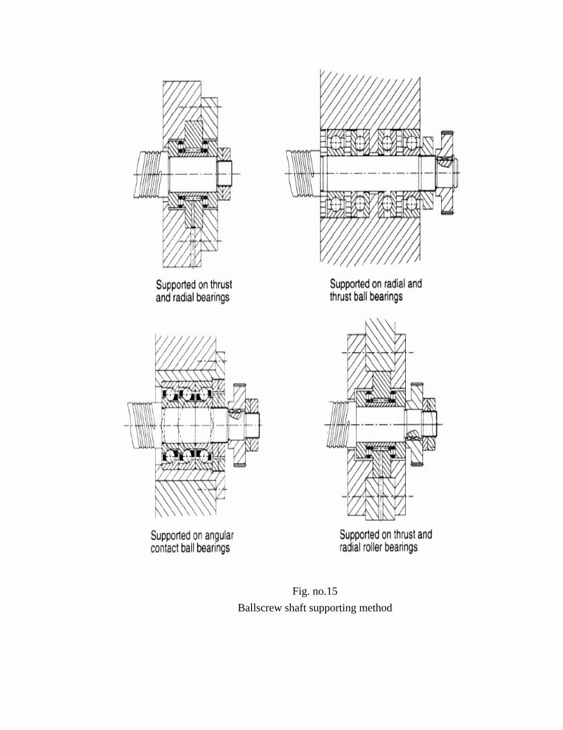
Fig. no.15 Ballscrew shaft supporting method

Due to the friction within a ball screw and nut, the movement of the slide produces temperature rise in the ball screw leading to its expansion. This results in compressive loading on the ball screw in case of fixed - fixed mounting. For this reason in such mounting arrangements ball screws are stretched to an extent of the expected thermal expansion. Fig. No.16 shows some examples of the stretching or pre-tensioning.
Adjustment by adjustment by thread Shim plate
Fig. no.16 Methods of pretensioning
Fig. no. 16
Bearings for ballscrew support
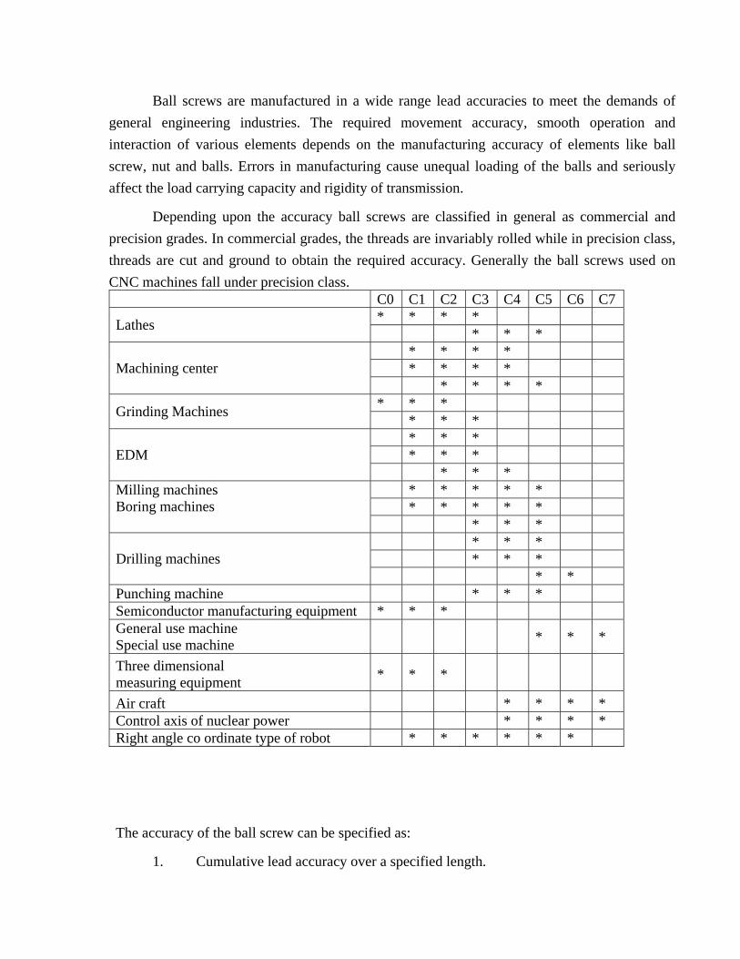
Ball screws are manufactured in a wide range lead accuracies to meet the demands of general engineering industries. The required movement accuracy, smooth operation and interaction of various elements depends on the manufacturing accuracy of elements like ball screw, nut and balls. Errors in manufacturing cause unequal loading of the balls and seriously affect the load carrying capacity and rigidity of transmission.
Depending upon the accuracy ball screws are classified in general as commercial and precision grades. In commercial grades, the threads are invariably rolled while in precision class, threads are cut and ground to obtain the required accuracy. Generally the ball screws used on CNC machines fall under precision class. C0 C1 C2 C3 C4 C5 C6 C7
* * * * Lathes * * * * * * * * * * * Machining center * * * * * * * Grinding Machines * * * * * * * * * EDM * * * * * * * * * * * * *
Milling machines Boring machines
* * * * * * * * * Drilling machines * *
Punching machine * * * Semiconductor manufacturing equipment * * * General use machine Special use machine
* * *
Three dimensional measuring equipment * * *
Air craft * * * * Control axis of nuclear power * * * * Right angle co ordinate type of robot * * * * * *
The accuracy of the ball screw can be specified as:
1. Cumulative lead accuracy over a specified length.

2. Total cumulative lead accuracy.
3. Fluctuations of cumulative lead accuracy over one revolution.
Depending on the above accuracy’s, The ball screws are classified into seven grades: C1,
C2, C3, C4, C5, C6 , & C7 . Fig. No. 17 gives the recommended accuracy grades for machine tool
applications.
ROLLERS SCREWS
There are two types of roller screws used planetary and re circulating. Both types provide
backlash-free movement and their efficiency is of the same order (90 %) as ball screws. An advantage of roller screws is that because the pitch of the screw is smaller that the minimum pitch of the ball screw, the less complex electronic circuitry will provide more accurate positional control. Roller screws are much costlier than the ball screws. The rollers of both types of screw are positioned between the nut and the screw, and engage with the thread from inside the nut and on the outside of the screw.
The planetary roller screws are shown in Fig No. 18 the rollers (3) in this type are threaded
as shown in fig. At each end of the rollers, gear teeth (7) are cut. The gear teeth mesh with an internally, toothed ring (8) on the nut (2) which drives the rollers to provide a rolling motion between the nut and the screw (1). The rollers are equally spaced around the shaft and are retained in their circumferential positions by SPI GOTS (4) which engage in locating rings (5) at each end of the nut. There is no axial movement of the rollers relative to the nut. The planetary roller screws are capable of transmitting high loads at fast speeds.
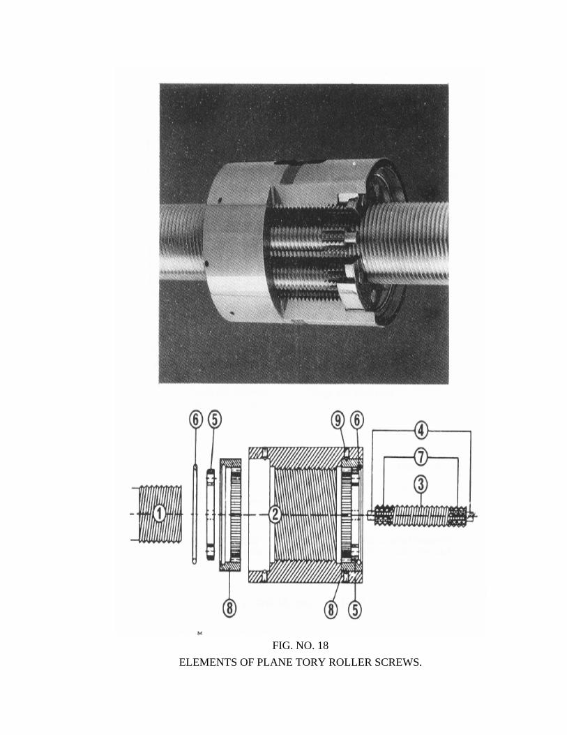
FIG. NO. 18
ELEMENTS OF PLANE TORY ROLLER SCREWS.
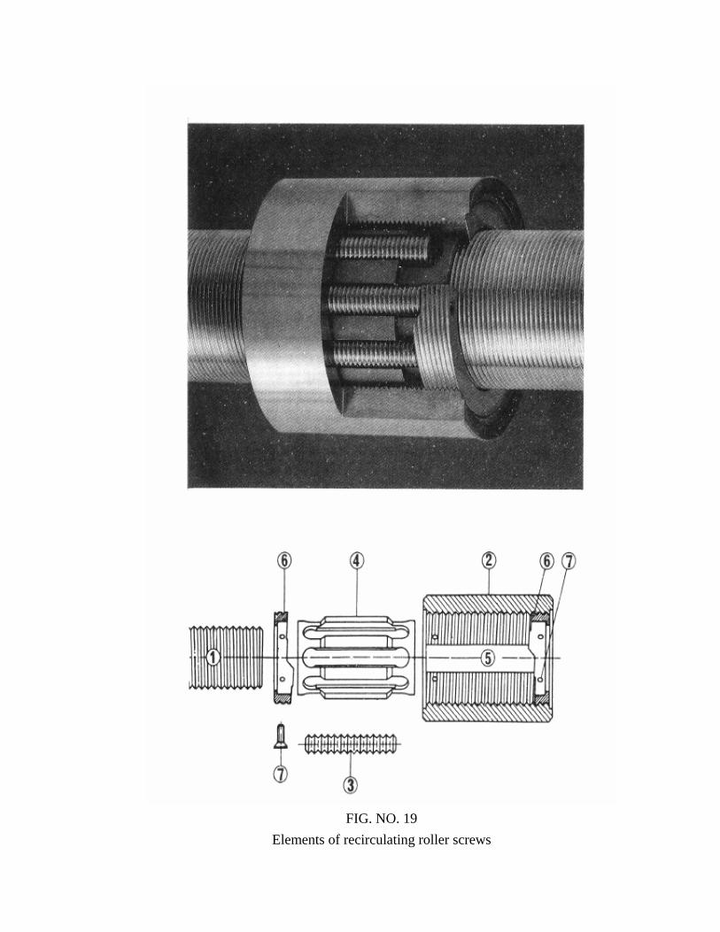
FIG. NO. 19
Elements of recirculating roller screws
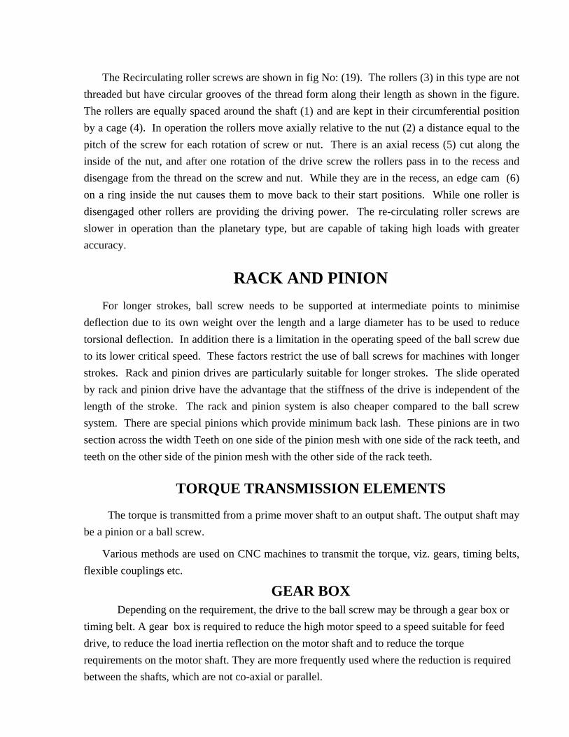
The Recirculating roller screws are shown in fig No: (19). The rollers (3) in this type are not threaded but have circular grooves of the thread form along their length as shown in the figure. The rollers are equally spaced around the shaft (1) and are kept in their circumferential position by a cage (4). In operation the rollers move axially relative to the nut (2) a distance equal to the pitch of the screw for each rotation of screw or nut. There is an axial recess (5) cut along the inside of the nut, and after one rotation of the drive screw the rollers pass in to the recess and disengage from the thread on the screw and nut. While they are in the recess, an edge cam (6) on a ring inside the nut causes them to move back to their start positions. While one roller is disengaged other rollers are providing the driving power. The re-circulating roller screws are slower in operation than the planetary type, but are capable of taking high loads with greater accuracy.
RACK AND PINION
For longer strokes, ball screw needs to be supported at intermediate points to minimise deflection due to its own weight over the length and a large diameter has to be used to reduce torsional deflection. In addition there is a limitation in the operating speed of the ball screw due to its lower critical speed. These factors restrict the use of ball screws for machines with longer strokes. Rack and pinion drives are particularly suitable for longer strokes. The slide operated by rack and pinion drive have the advantage that the stiffness of the drive is independent of the length of the stroke. The rack and pinion system is also cheaper compared to the ball screw system. There are special pinions which provide minimum back lash. These pinions are in two section across the width Teeth on one side of the pinion mesh with one side of the rack teeth, and teeth on the other side of the pinion mesh with the other side of the rack teeth.
TORQUE TRANSMISSION ELEMENTS
The torque is transmitted from a prime mover shaft to an output shaft. The output shaft may be a pinion or a ball screw.
Various methods are used on CNC machines to transmit the torque, viz. gears, timing belts, flexible couplings etc.
GEAR BOX Depending on the requirement, the drive to the ball screw may be through a gear box or timing belt. A gear box is required to reduce the high motor speed to a speed suitable for feed drive, to reduce the load inertia reflection on the motor shaft and to reduce the torque requirements on the motor shaft. They are more frequently used where the reduction is required between the shafts, which are not co-axial or parallel.
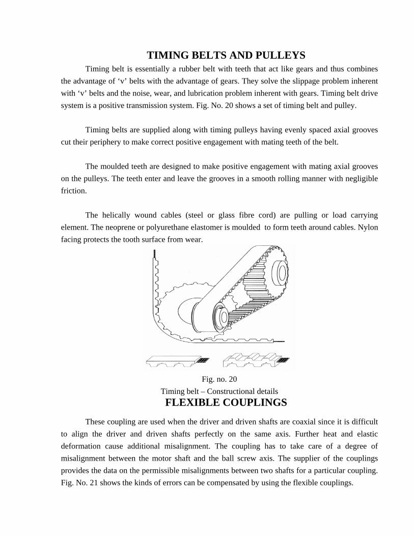
TIMING BELTS AND PULLEYS Timing belt is essentially a rubber belt with teeth that act like gears and thus combines
the advantage of ‘v’ belts with the advantage of gears. They solve the slippage problem inherent with ‘v’ belts and the noise, wear, and lubrication problem inherent with gears. Timing belt drive system is a positive transmission system. Fig. No. 20 shows a set of timing belt and pulley.
Timing belts are supplied along with timing pulleys having evenly spaced axial grooves
cut their periphery to make correct positive engagement with mating teeth of the belt. The moulded teeth are designed to make positive engagement with mating axial grooves
on the pulleys. The teeth enter and leave the grooves in a smooth rolling manner with negligible friction.
The helically wound cables (steel or glass fibre cord) are pulling or load carrying
element. The neoprene or polyurethane elastomer is moulded to form teeth around cables. Nylon facing protects the tooth surface from wear.
Fig. no. 20
Timing belt – Constructional details FLEXIBLE COUPLINGS
These coupling are used when the driver and driven shafts are coaxial since it is difficult to align the driver and driven shafts perfectly on the same axis. Further heat and elastic deformation cause additional misalignment. The coupling has to take care of a degree of misalignment between the motor shaft and the ball screw axis. The supplier of the couplings provides the data on the permissible misalignments between two shafts for a particular coupling. Fig. No. 21 shows the kinds of errors can be compensated by using the flexible couplings.
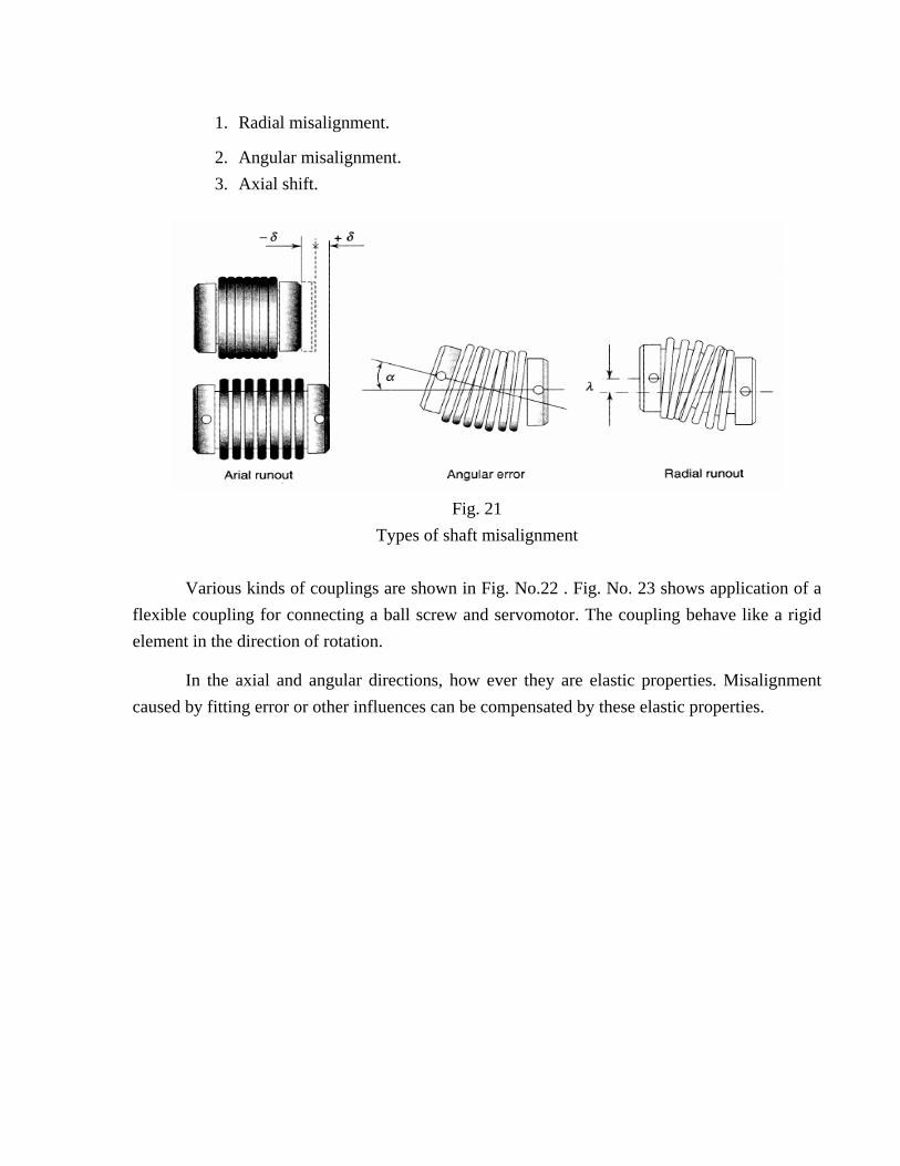
1. Radial misalignment.
2. Angular misalignment. 3. Axial shift.
Fig. 21
Types of shaft misalignment
Various kinds of couplings are shown in Fig. No.22 . Fig. No. 23 shows application of a flexible coupling for connecting a ball screw and servomotor. The coupling behave like a rigid element in the direction of rotation.
In the axial and angular directions, how ever they are elastic properties. Misalignment caused by fitting error or other influences can be compensated by these elastic properties.
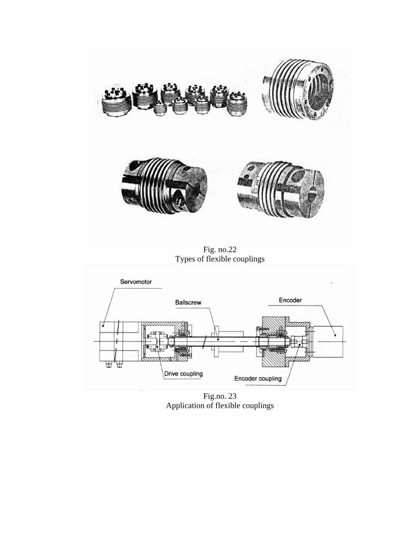
Fig. no.22
Types of flexible couplings
Fig.no. 23
Application of flexible couplings
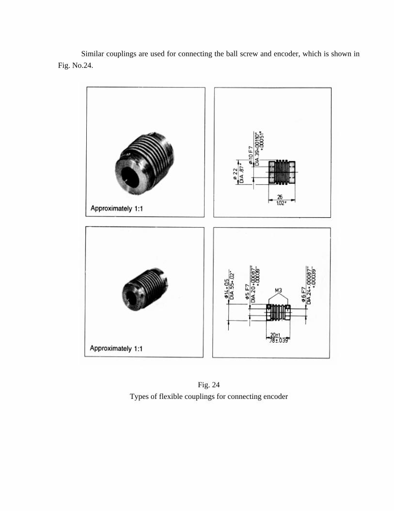
Similar couplings are used for connecting the ball screw and encoder, which is shown in Fig. No.24.
Fig. 24 Types of flexible couplings for connecting encoder
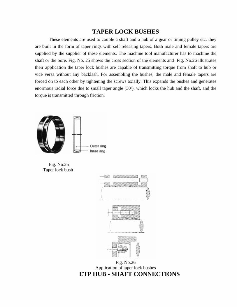
TAPER LOCK BUSHES These elements are used to couple a shaft and a hub of a gear or timing pulley etc. they are built in the form of taper rings with self releasing tapers. Both male and female tapers are supplied by the supplier of these elements. The machine tool manufacturer has to machine the shaft or the bore. Fig. No. 25 shows the cross section of the elements and Fig. No.26 illustrates their application the taper lock bushes are capable of transmitting torque from shaft to hub or vice versa without any backlash. For assembling the bushes, the male and female tapers are forced on to each other by tightening the screws axially. This expands the bushes and generates enormous radial force due to small taper angle (300), which locks the hub and the shaft, and the torque is transmitted through friction.
Fig. No.25 Taper lock bush
Fig. No.26
Application of taper lock bushes ETP HUB - SHAFT CONNECTIONS
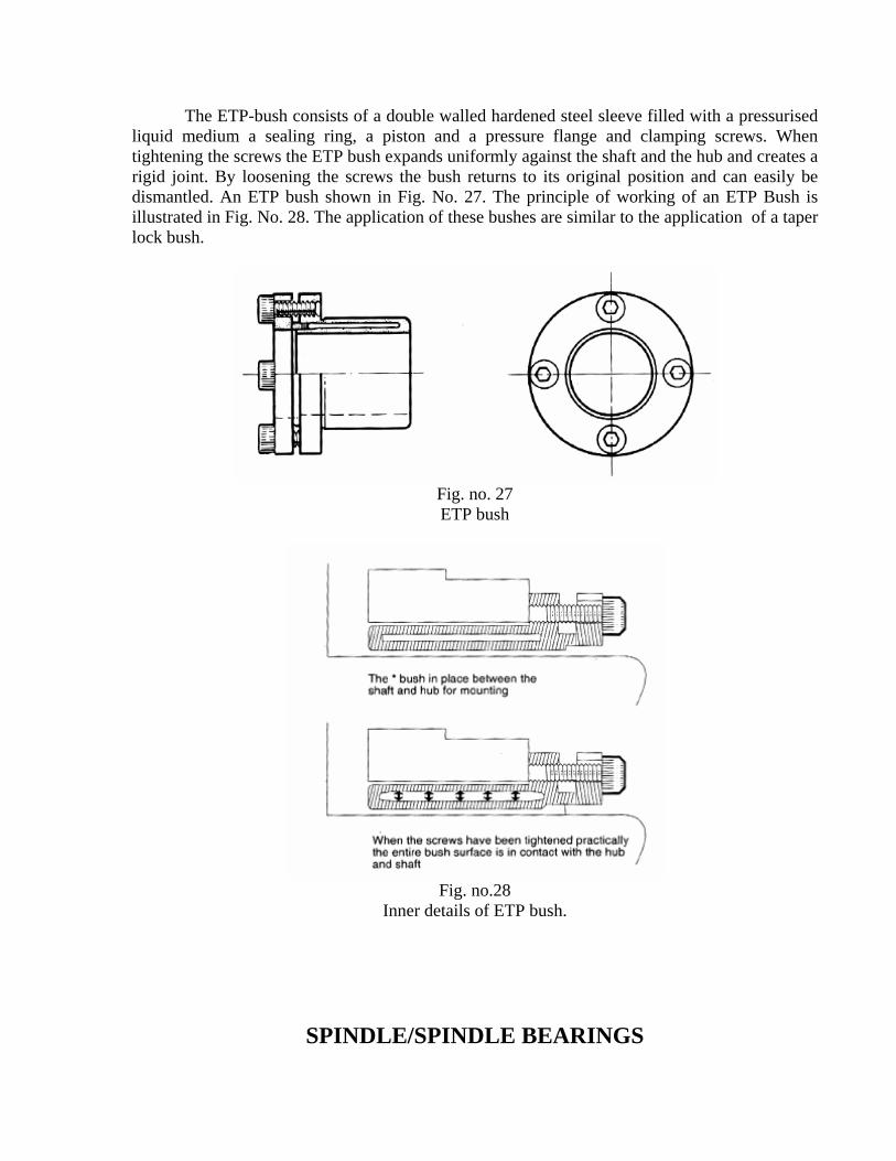
The ETP-bush consists of a double walled hardened steel sleeve filled with a pressurised liquid medium a sealing ring, a piston and a pressure flange and clamping screws. When tightening the screws the ETP bush expands uniformly against the shaft and the hub and creates a rigid joint. By loosening the screws the bush returns to its original position and can easily be dismantled. An ETP bush shown in Fig. No. 27. The principle of working of an ETP Bush is illustrated in Fig. No. 28. The application of these bushes are similar to the application of a taper lock bush.
Fig. no. 27 ETP bush
Fig. no.28
Inner details of ETP bush.
SPINDLE/SPINDLE BEARINGS
Material removal using single point or multi point tools requires rotational speeds of the order of 30 to 6000 rpm and even higher. All work or tool carrying spindles rotating at these speeds are subjected to torsional and radial deflections. They are also subjected to thrust forces depending on the nature of the work being performed. To increase the stiffness and minimise torsional strain on the spindles they are designed to be a stiff as possible with a minimum over hang. Also the final drive to the spindle should be located as near as possible to the bearings.
When a work holder (such as a chuck) is mounted on the spindle, the accuracy of rotation is extremely important as it effects the roundness of the components produced. The rotational accuracy of the spindle is dependent on the quality and design of the bearings used and the pre loading. The bearings should support the spindle radially and axially.
The accuracy and the quality of the work produced directly depends on the geometrical accuracy, running accuracy and the stiffness of the spindle assembly. Various types of spindle bearings used in the design of a spindle for machine tools are:
1. Hydrodynamic bearings.
2. Hydrostatic bearings.
3. Anti friction bearings.
HYDRO DYNAMIC BEARINGS Hydro dynamic bearings are journal bearings with a thin film of oil between the spindle
and the journal. These are used where the load carrying capacities are low and frequent starting and stopping of the spindle is not required: for example grinding machines. The essential features of these bearings include simplicity, good damping properties and good running accuracy.
The principle of the hydro dynamic bearing is explained in Fig. No. 29. The pressure of
the oil is created within the bearing by the rotation of the spindle. As the spindle rotates, the oil
in contact with the spindle is carried into wedge-shaped cavities between the spindle and the
bearing. The oil pressure is increased as the oil is forced through the small clearances between
the bearing and the spindle. The main limitation in a hydro dynamic bearing is that a definite
clearance must be provided for the bearing. This clearance may result in the centre of a spindle in
the bearing to change its position owing to variation of the applied force. Clearances normally
provided between the spindle and bore of the bearing for the oil film vary from 50 microns upto
200 microns depending upon the diameter of the journal.
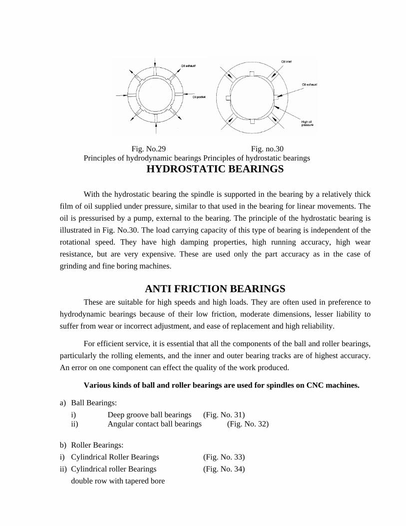
Fig. No.29 Fig. no.30 Principles of hydrodynamic bearings Principles of hydrostatic bearings
HYDROSTATIC BEARINGS With the hydrostatic bearing the spindle is supported in the bearing by a relatively thick
film of oil supplied under pressure, similar to that used in the bearing for linear movements. The oil is pressurised by a pump, external to the bearing. The principle of the hydrostatic bearing is illustrated in Fig. No.30. The load carrying capacity of this type of bearing is independent of the rotational speed. They have high damping properties, high running accuracy, high wear resistance, but are very expensive. These are used only the part accuracy as in the case of grinding and fine boring machines.
ANTI FRICTION BEARINGS These are suitable for high speeds and high loads. They are often used in preference to hydrodynamic bearings because of their low friction, moderate dimensions, lesser liability to suffer from wear or incorrect adjustment, and ease of replacement and high reliability.
For efficient service, it is essential that all the components of the ball and roller bearings, particularly the rolling elements, and the inner and outer bearing tracks are of highest accuracy. An error on one component can effect the quality of the work produced.
Various kinds of ball and roller bearings are used for spindles on CNC machines.
a) Ball Bearings: i) Deep groove ball bearings (Fig. No. 31)
ii) Angular contact ball bearings (Fig. No. 32) b) Roller Bearings: i) Cylindrical Roller Bearings (Fig. No. 33) ii) Cylindrical roller Bearings (Fig. No. 34) double row with tapered bore
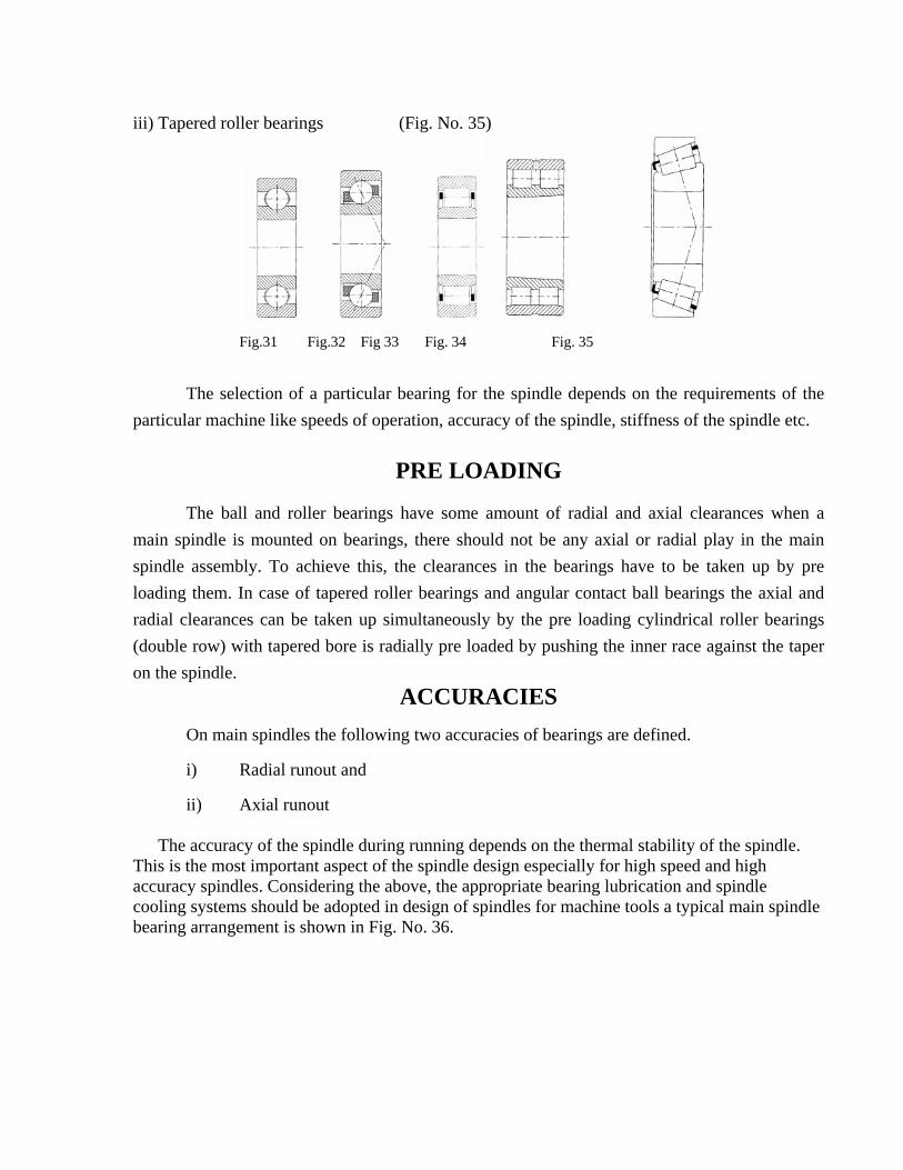
iii) Tapered roller bearings (Fig. No. 35)
Fig.31 Fig.32 Fig 33 Fig. 34 Fig. 35
The selection of a particular bearing for the spindle depends on the requirements of the particular machine like speeds of operation, accuracy of the spindle, stiffness of the spindle etc.
PRE LOADING
The ball and roller bearings have some amount of radial and axial clearances when a main spindle is mounted on bearings, there should not be any axial or radial play in the main spindle assembly. To achieve this, the clearances in the bearings have to be taken up by pre loading them. In case of tapered roller bearings and angular contact ball bearings the axial and radial clearances can be taken up simultaneously by the pre loading cylindrical roller bearings (double row) with tapered bore is radially pre loaded by pushing the inner race against the taper on the spindle.
ACCURACIES On main spindles the following two accuracies of bearings are defined.
i) Radial runout and
ii) Axial runout
The accuracy of the spindle during running depends on the thermal stability of the spindle. This is the most important aspect of the spindle design especially for high speed and high accuracy spindles. Considering the above, the appropriate bearing lubrication and spindle cooling systems should be adopted in design of spindles for machine tools a typical main spindle bearing arrangement is shown in Fig. No. 36.
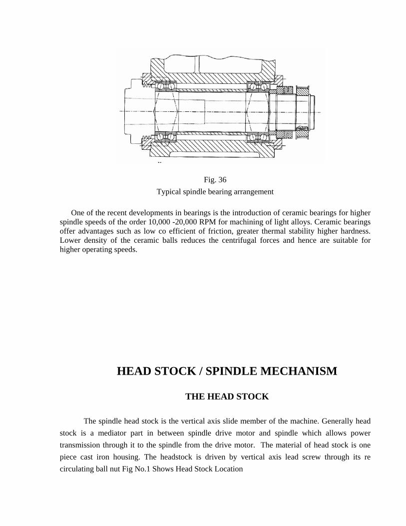
Fig. 36 Typical spindle bearing arrangement
One of the recent developments in bearings is the introduction of ceramic bearings for higher
spindle speeds of the order 10,000 -20,000 RPM for machining of light alloys. Ceramic bearings offer advantages such as low co efficient of friction, greater thermal stability higher hardness. Lower density of the ceramic balls reduces the centrifugal forces and hence are suitable for higher operating speeds.
HEAD STOCK / SPINDLE MECHANISM
THE HEAD STOCK
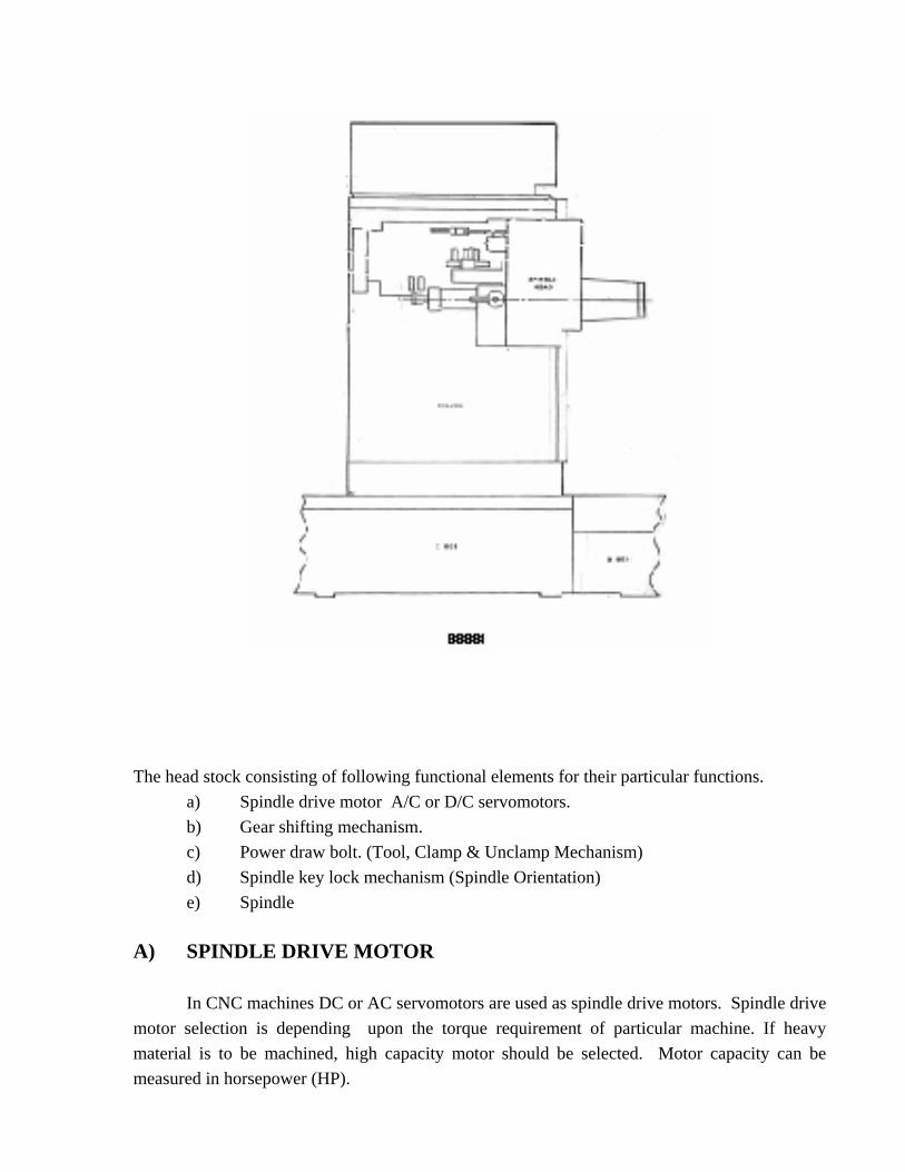
The spindle head stock is the vertical axis slide member of the machine. Generally head stock is a mediator part in between spindle drive motor and spindle which allows power transmission through it to the spindle from the drive motor. The material of head stock is one piece cast iron housing. The headstock is driven by vertical axis lead screw through its re circulating ball nut Fig No.1 Shows Head Stock Location
The head stock consisting of following functional elements for their particular functions. a) Spindle drive motor A/C or D/C servomotors. b) Gear shifting mechanism. c) Power draw bolt. (Tool, Clamp & Unclamp Mechanism) d) Spindle key lock mechanism (Spindle Orientation) e) Spindle A) SPINDLE DRIVE MOTOR In CNC machines DC or AC servomotors are used as spindle drive motors. Spindle drive motor selection is depending upon the torque requirement of particular machine. If heavy material is to be machined, high capacity motor should be selected. Motor capacity can be measured in horsepower (HP).
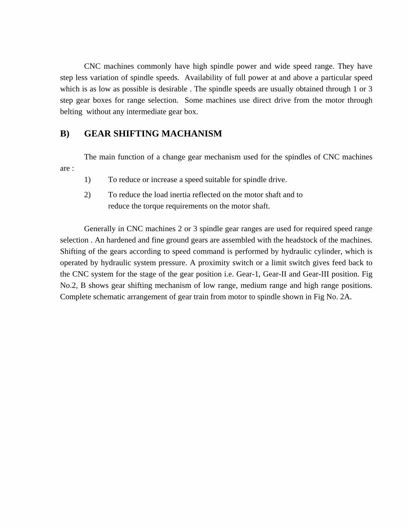
CNC machines commonly have high spindle power and wide speed range. They have step less variation of spindle speeds. Availability of full power at and above a particular speed which is as low as possible is desirable . The spindle speeds are usually obtained through 1 or 3 step gear boxes for range selection. Some machines use direct drive from the motor through belting without any intermediate gear box. B) GEAR SHIFTING MACHANISM The main function of a change gear mechanism used for the spindles of CNC machines are : 1) To reduce or increase a speed suitable for spindle drive.
2) To reduce the load inertia reflected on the motor shaft and to reduce the torque requirements on the motor shaft. Generally in CNC machines 2 or 3 spindle gear ranges are used for required speed range selection . An hardened and fine ground gears are assembled with the headstock of the machines. Shifting of the gears according to speed command is performed by hydraulic cylinder, which is operated by hydraulic system pressure. A proximity switch or a limit switch gives feed back to the CNC system for the stage of the gear position i.e. Gear-1, Gear-II and Gear-III position. Fig No.2, B shows gear shifting mechanism of low range, medium range and high range positions. Complete schematic arrangement of gear train from motor to spindle shown in Fig No. 2A.
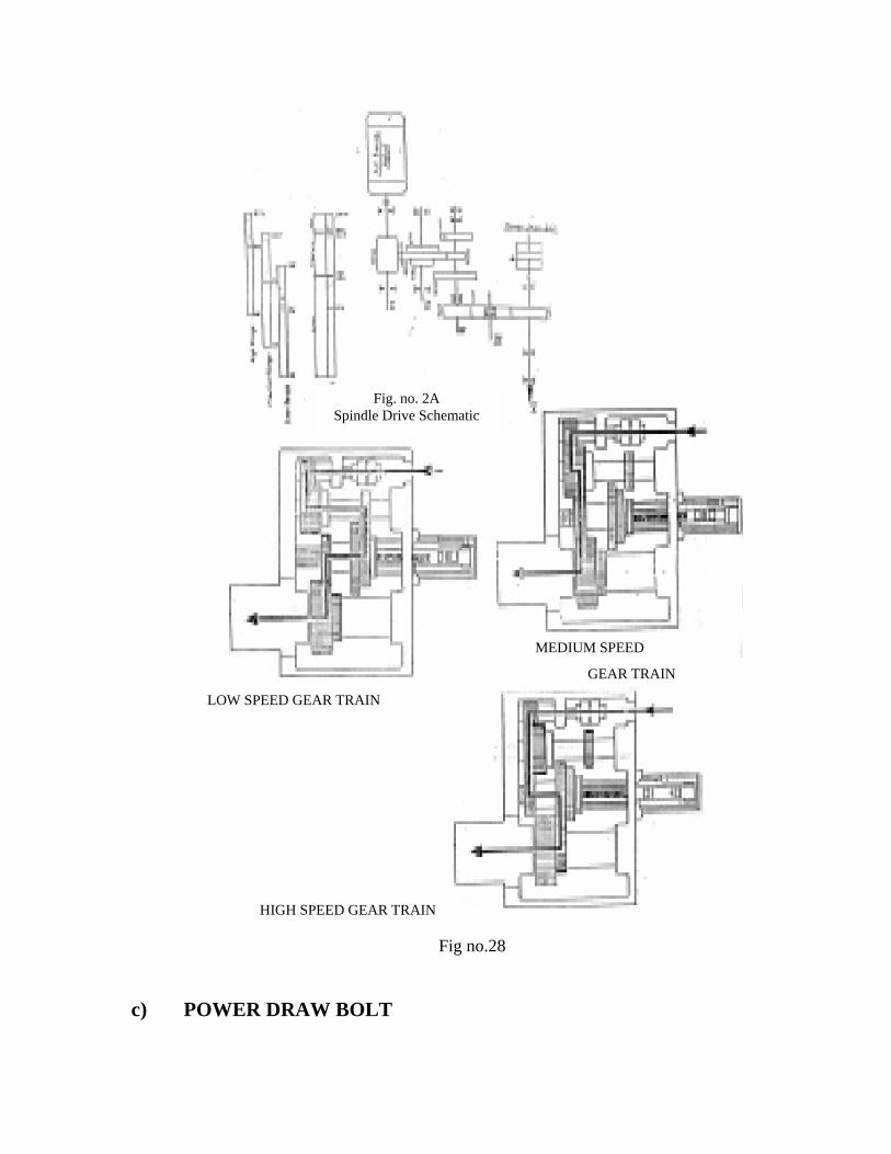
Fig. no. 2A Spindle Drive Schematic
N
c) PO
LOW SPEED GEAR TRAIN
Fig no.28
WER DRAW BOLT
MEDIUM SPEED
GEAR TRAI
HIGH SPEED GEAR TRAIN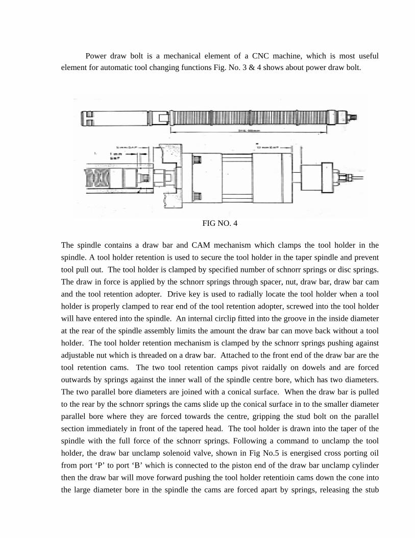
Power draw bolt is a mechanical element of a CNC machine, which is most useful element for automatic tool changing functions Fig. No. 3 & 4 shows about power draw bolt.
FIG NO. 4
The spindle contains a draw bar and CAM mechanism which clamps the tool holder in the spindle. A tool holder retention is used to secure the tool holder in the taper spindle and prevent tool pull out. The tool holder is clamped by specified number of schnorr springs or disc springs. The draw in force is applied by the schnorr springs through spacer, nut, draw bar, draw bar cam and the tool retention adopter. Drive key is used to radially locate the tool holder when a tool holder is properly clamped to rear end of the tool retention adopter, screwed into the tool holder will have entered into the spindle. An internal circlip fitted into the groove in the inside diameter at the rear of the spindle assembly limits the amount the draw bar can move back without a tool holder. The tool holder retention mechanism is clamped by the schnorr springs pushing against adjustable nut which is threaded on a draw bar. Attached to the front end of the draw bar are the tool retention cams. The two tool retention camps pivot raidally on dowels and are forced outwards by springs against the inner wall of the spindle centre bore, which has two diameters. The two parallel bore diameters are joined with a conical surface. When the draw bar is pulled to the rear by the schnorr springs the cams slide up the conical surface in to the smaller diameter parallel bore where they are forced towards the centre, gripping the stud bolt on the parallel section immediately in front of the tapered head. The tool holder is drawn into the taper of the spindle with the full force of the schnorr springs. Following a command to unclamp the tool holder, the draw bar unclamp solenoid valve, shown in Fig No.5 is energised cross porting oil from port ‘P’ to port ‘B’ which is connected to the piston end of the draw bar unclamp cylinder then the draw bar will move forward pushing the tool holder retentioin cams down the cone into the large diameter bore in the spindle the cams are forced apart by springs, releasing the stub
bolt. The steel operating button screwed into the draw bar. Pushes in the flat rear surface of the stub botl to give 0.1mm knock out of the tool holder.
d) Spindle key lock mechanism.
This feature enables the spindle to be stopped positive radial position by means of auxiliary function incorporated in the system. This mechanism is housed in front position of head. The mechanism of key lock is shown in Fig. No.6 piston is normally withdrawn position through hydraulic pressure Fig.No.7 on receipt of command from CNC control spindle is rotated clockwise (looking through rear of the spindle) and shift gear is positioned to middle range. Solenoid of HYD. Directional control valve is energised and piston moves forward to contact key lock ring. A small step in this ring indicates approach of positioning notch and proximity switch, spindle motor is stopped and during little further rotation of spindle, the piston enters the notch in the key ring and holds the spindle in positive radial position. Proximity switch senses the completion of spindle key lock function.
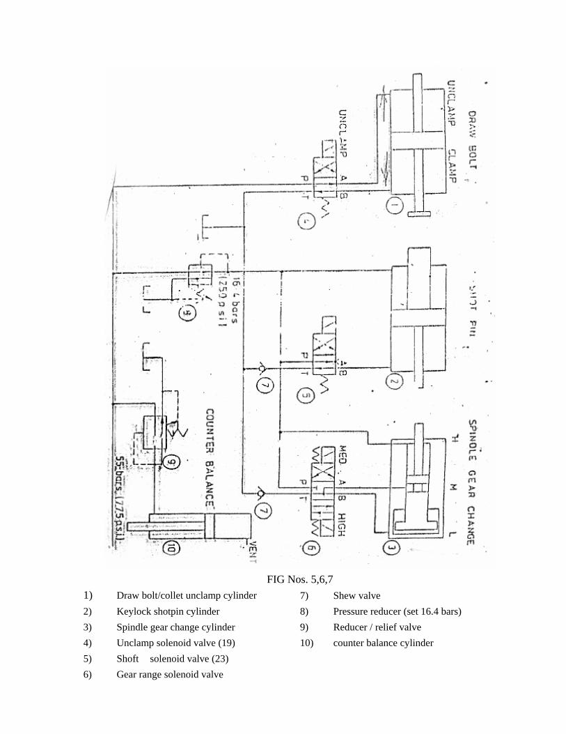
FIG Nos. 5,6,7
1) Draw bolt/collet unclamp cylinder 2) Keylock shotpin cylinder 3) Spindle gear change cylinder 4) Unclamp solenoid valve (19) 5) Shoft solenoid valve (23) 6) Gear range solenoid valve
7) Shew valve 8) Pressure reducer (set 16.4 bars) 9) Reducer / relief valve 10) counter balance cylinder
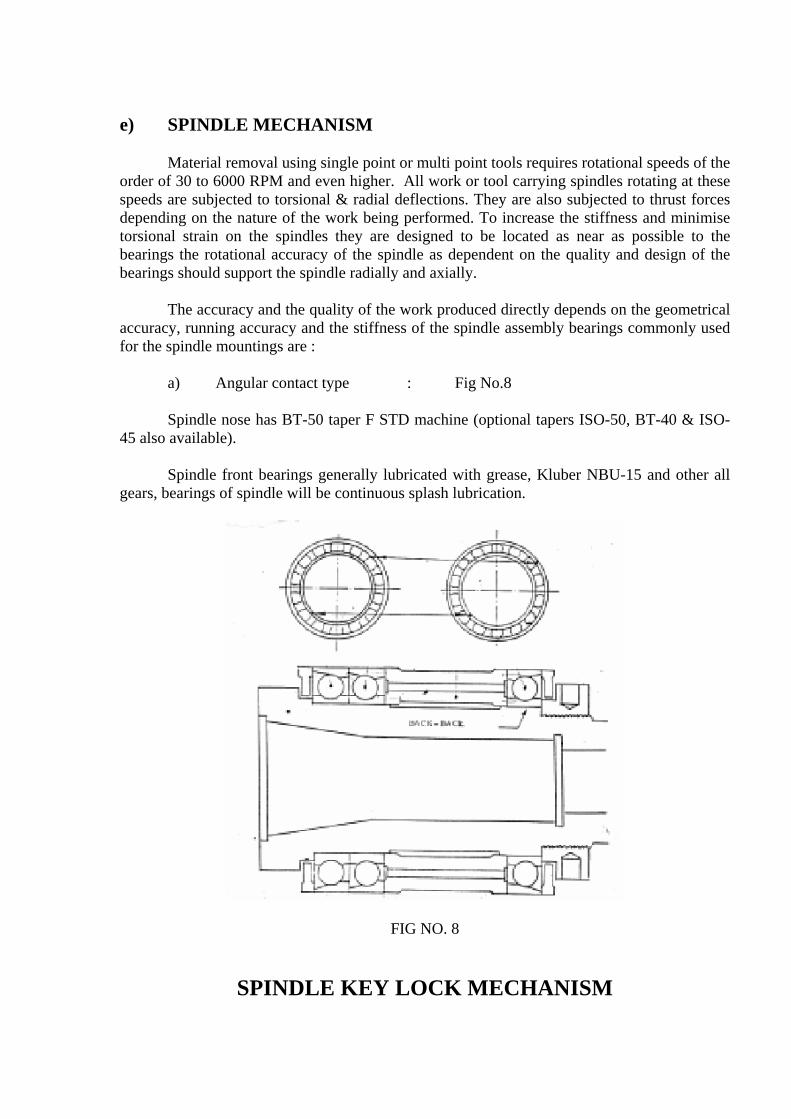
e) SPINDLE MECHANISM Material removal using single point or multi point tools requires rotational speeds of the order of 30 to 6000 RPM and even higher. All work or tool carrying spindles rotating at these speeds are subjected to torsional & radial deflections. They are also subjected to thrust forces depending on the nature of the work being performed. To increase the stiffness and minimise torsional strain on the spindles they are designed to be located as near as possible to the bearings the rotational accuracy of the spindle as dependent on the quality and design of the bearings should support the spindle radially and axially. The accuracy and the quality of the work produced directly depends on the geometrical accuracy, running accuracy and the stiffness of the spindle assembly bearings commonly used for the spindle mountings are : a) Angular contact type : Fig No.8 Spindle nose has BT-50 taper F STD machine (optional tapers ISO-50, BT-40 & ISO-45 also available). Spindle front bearings generally lubricated with grease, Kluber NBU-15 and other all gears, bearings of spindle will be continuous splash lubrication.
FIG NO. 8
SPINDLE KEY LOCK MECHANISM
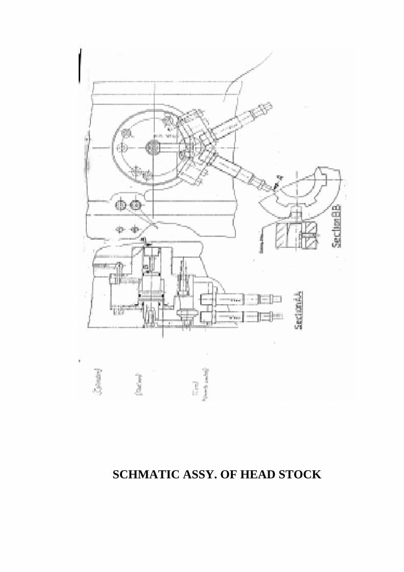
SCHMATIC ASSY. OF HEAD STOCK
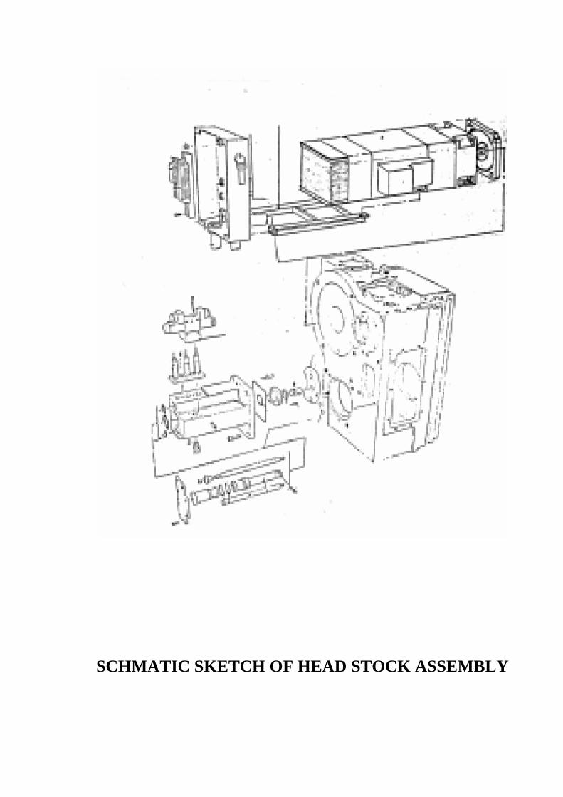
SCHMATIC SKETCH OF HEAD STOCK ASSEMBLY
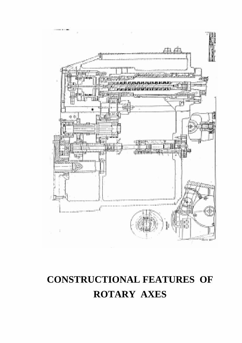
CONSTRUCTIONAL FEATURES OF ROTARY AXES
ELEMENTS
• CURVIC COUPLING
• CLAMPING AND UNCLAMPING OF TABLE
• DRIVE TO TABLE
• ENCODER TO MEASURE THE ANGLE OF ROTATION
• TABLE UP/DOWN, CLAMP/UNCLAMP SENSORS TO CHECK
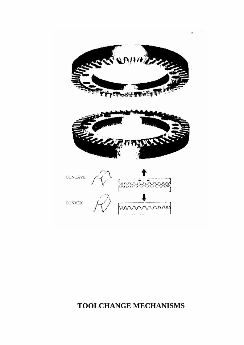
CURVIC COUPLING
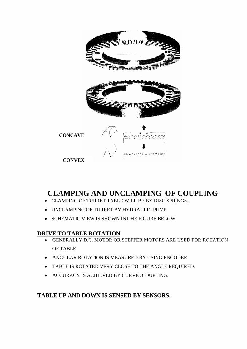
CONCAVE
CONVEX
CLAMPING AND UNCLAMPING OF COUPLING • CLAMPING OF TURRET TABLE WILL BE BY DISC SPRINGS.
• UNCLAMPING OF TURRET BY HYDRAULIC PUMP
• SCHEMATIC VIEW IS SHOWN INT HE FIGURE BELOW.
DRIVE TO TABLE ROTATION
• GENERALLY D.C. MOTOR OR STEPPER MOTORS ARE USED FOR ROTATION
OF TABLE.
• ANGULAR ROTATION IS MEASURED BY USING ENCODER.
• TABLE IS ROTATED VERY CLOSE TO THE ANGLE REQUIRED.
• ACCURACY IS ACHIEVED BY CURVIC COUPLING.
TABLE UP AND DOWN IS SENSED BY SENSORS.
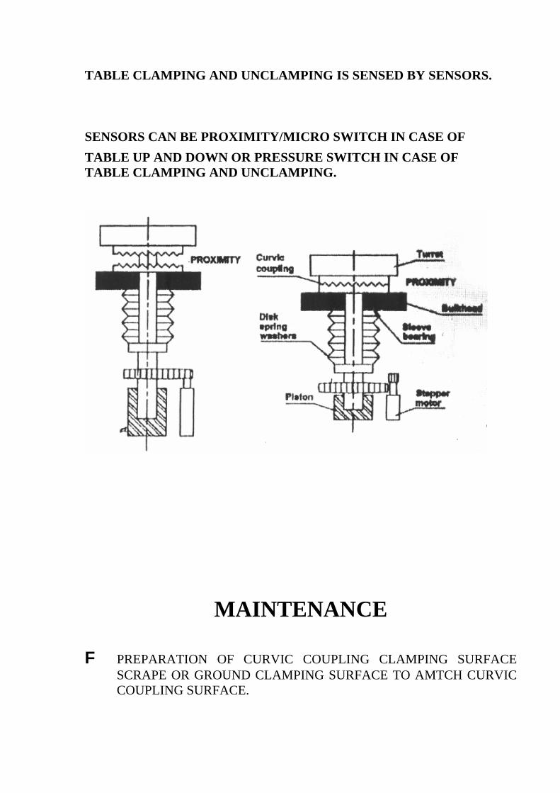
TABLE CLAMPING AND UNCLAMPING IS SENSED BY SENSORS. SENSORS CAN BE PROXIMITY/MICRO SWITCH IN CASE OF TABLE UP AND DOWN OR PRESSURE SWITCH IN CASE OF TABLE CLAMPING AND UNCLAMPING.
MAINTENANCE
F PREPARATION OF CURVIC COUPLING CLAMPING SURFACE SCRAPE OR GROUND CLAMPING SURFACE TO AMTCH CURVIC COUPLING SURFACE.
• RIGID CLAMPING OF CURVIC COUPLINGS.
• CONTROL THE FACIAL AND RADIAL RUNOUTS ON THE TOOTH SURFACE AS PER THE RECOMMENDATIONS OF CURVIC COUPLING MANUFACTURER.
• CORRECT CLAMPING OF MOVABLE COUPLINGS TO
STATIONARY COUPLINGS BY HYDRAULICS OR DISC SPRINGS.
ROTARY TABLE
• TYPES OF WORM GEAR DRIVES
CYLINDRICAL WORM AND SPUR GEAR. CYLINDRICAL WORM AND THROATED WORM GEAR DEEP TOOTH CYLINDRICAL WORM AND THROATED WORM GEAR.
ENVELOPING WORM AND SPUR DRIVE AND SPUR GEAR WILDHABEAR WORM DRIVE AND SPUR GEAR
DOUBLE ENVELOPING WORM AND THROATED GEAR.
IMPORTANT ASPECT IN ROTARY TABLE IS TO ELIMINATE BACKLASH.
METHODS TO ELIMINATE BACKLASH IN WORMWHEEL AND WORM
* DUPLEX WORM WITH TWO PITCHES. BY AXIALLY ADVANCING THE WORM, THE CLEARANCE IN THE
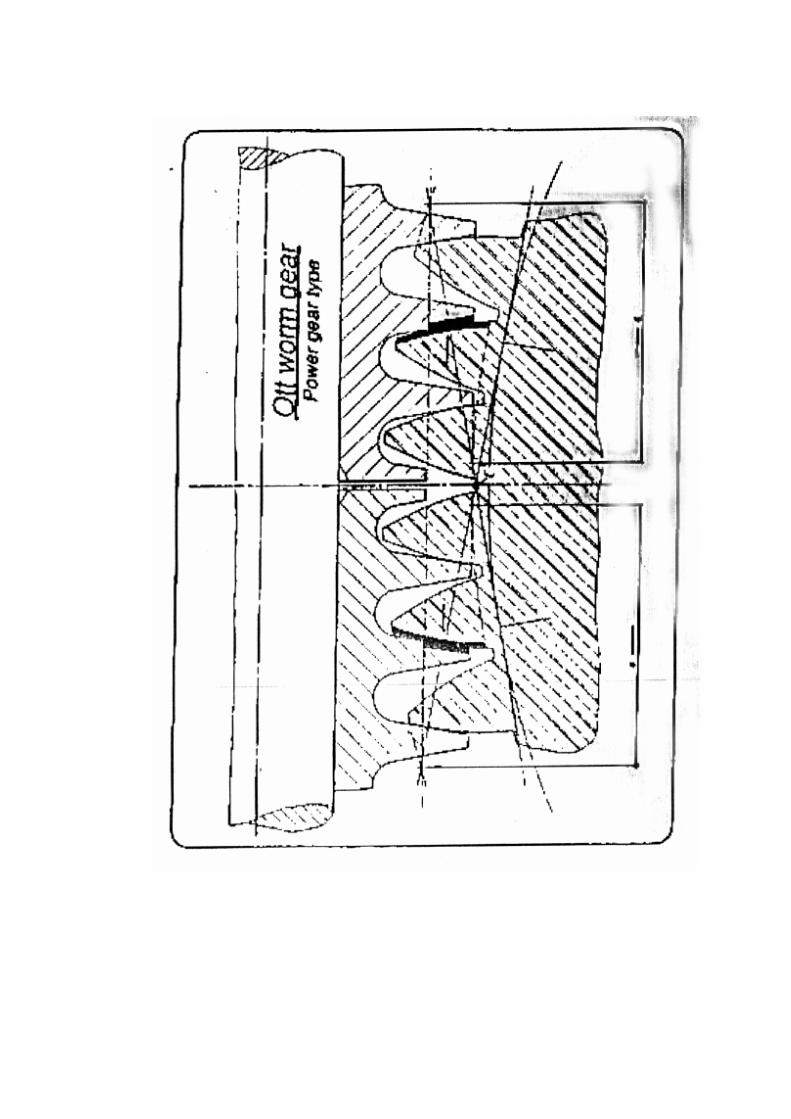
WORM AND WORM WHEEL CAN BE CLOSED. * OTT WORM AND WORM GEAR

BY AXILLARY ADVANCING THE MOVABLE WORM WITH RESPECT TO THE FIXED WORM. THE CLEARANCE IN THE WORM AND WORM GEAR CAN BE CLOSED.
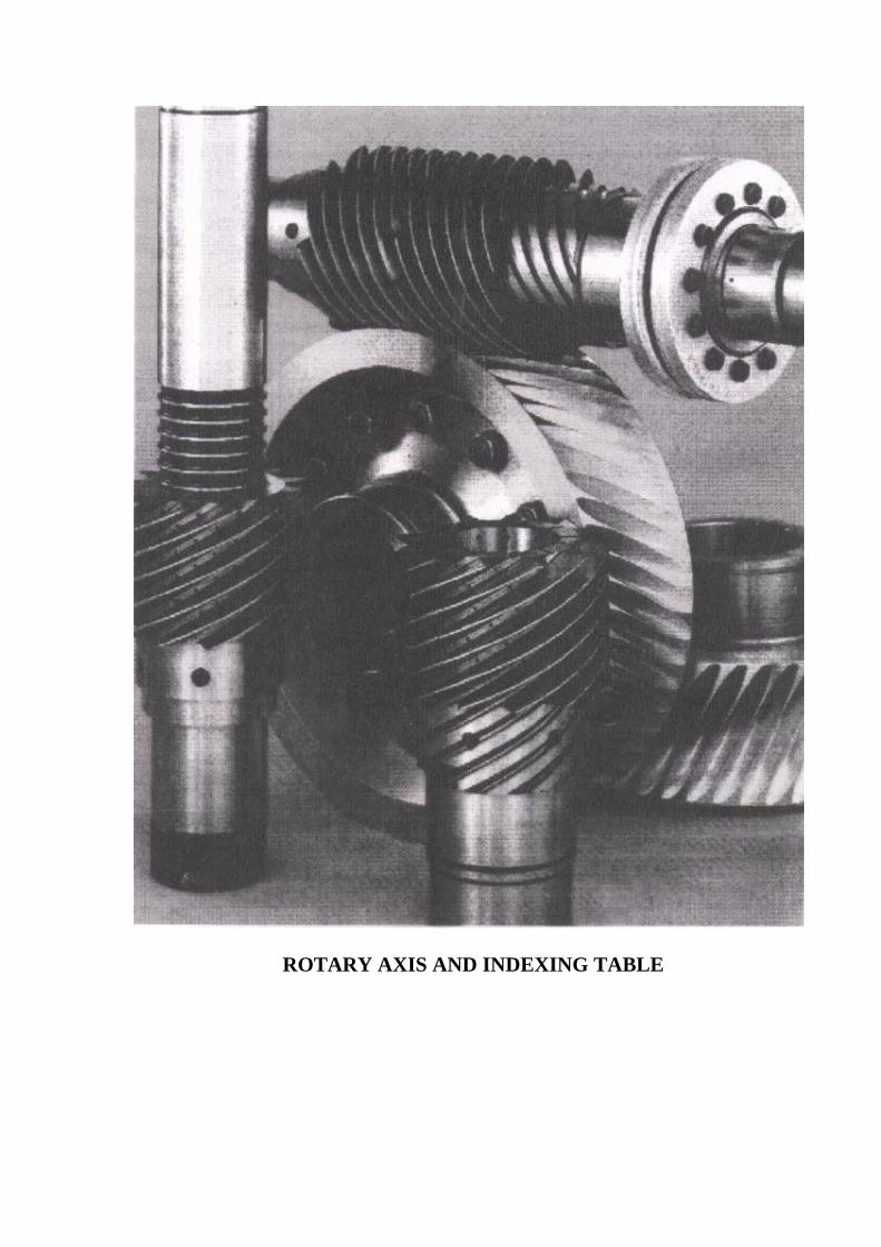
ROTARY AXIS AND INDEXING TABLE
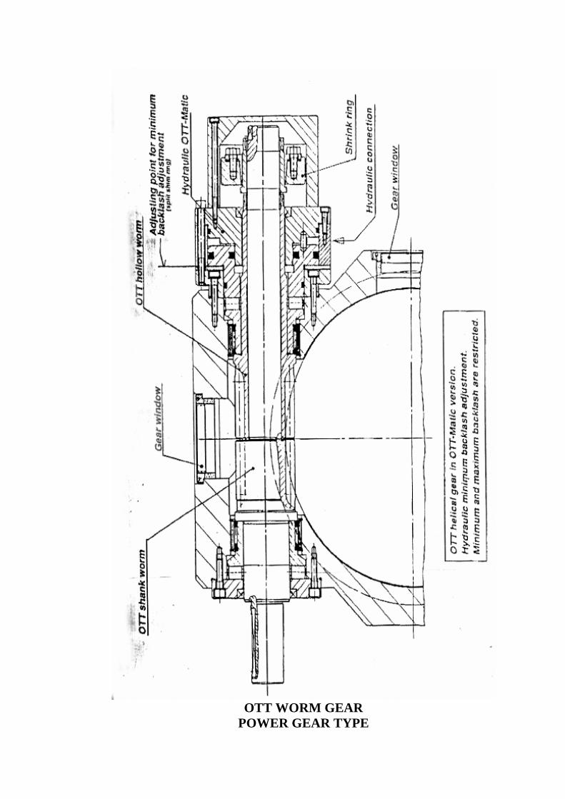
OTT WORM GEAR
POWER GEAR TYPE
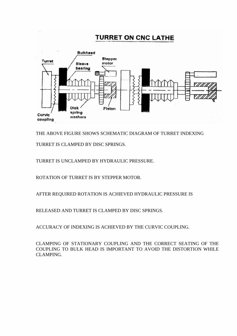
THE ABOVE FIGURE SHOWS SCHEMATIC DIAGRAM OF TURRET INDEXING TURRET IS CLAMPED BY DISC SPRINGS.
TURRET IS UNCLAMPED BY HYDRAULIC PRESSURE.
ROTATION OF TURRET IS BY STEPPER MOTOR.
AFTER REQUIRED ROTATION IS ACHIEVED HYDRAULIC PRESSURE IS
RELEASED AND TURRET IS CLAMPED BY DISC SPRINGS.
ACCURACY OF INDEXING IS ACHIEVED BY THE CURVIC COUPLING.
CLAMPING OF STATIONARY COUPLING AND THE CORRECT SEATING OF THE COUPLING TO BULK HEAD IS IMPORTANT TO AVOID THE DISTORTION WHILE CLAMPING.
X
CONVETOOLCHANGE MECHANISMS
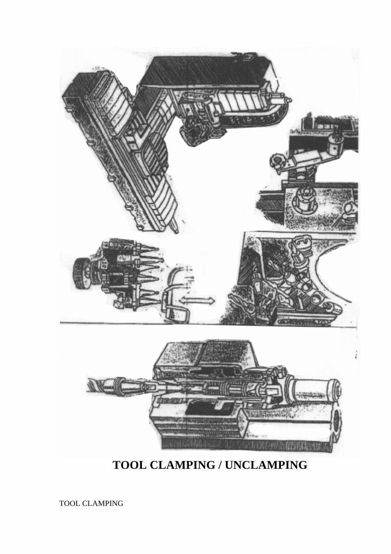
TOOL CLAMPING / UNCLAMPING
TOOL CLAMPING

GENERALLY HELD IN SPINDLE BY DISC SPRINGS WITH THE HELP OF RETENTION STUD. THIS CONDITION IS SENSED BY PROXIMITY SWITCH. UNCLAMPING OF TOOL DISC SPRINGS ARE COMPRESSED BY HYDRAULIC CYLINDER. BY COMPRESSION OF DISC SPRINGS THE GRIPPER FINGUERS ARE OPENED AND TOOL CAN BE TAKEN OUT. TOOL UNCLAMPING IS SENSED BY THE PROXIMITY SWITCH WITH CYLINDER DOWN POSITION.
TOOL GRIPPED IN GRIPPER ARM BY FINGERS
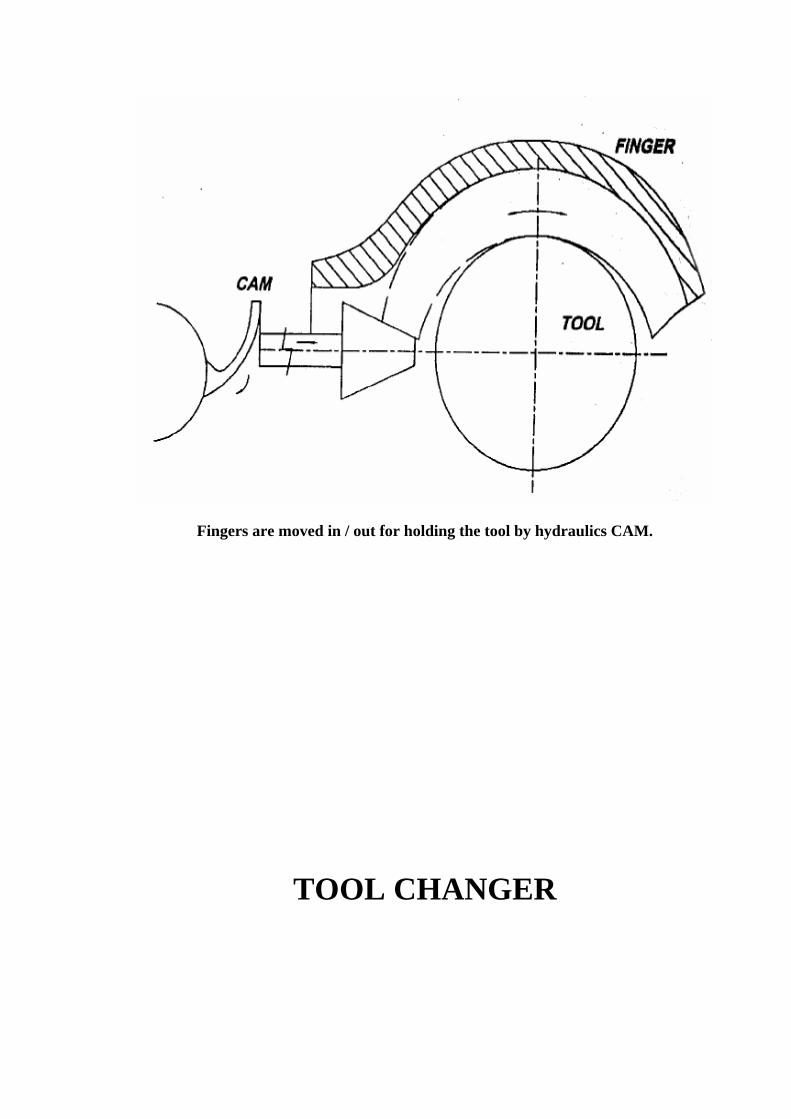
Fingers are moved in / out for holding the tool by hydraulics CAM.
TOOL CHANGER
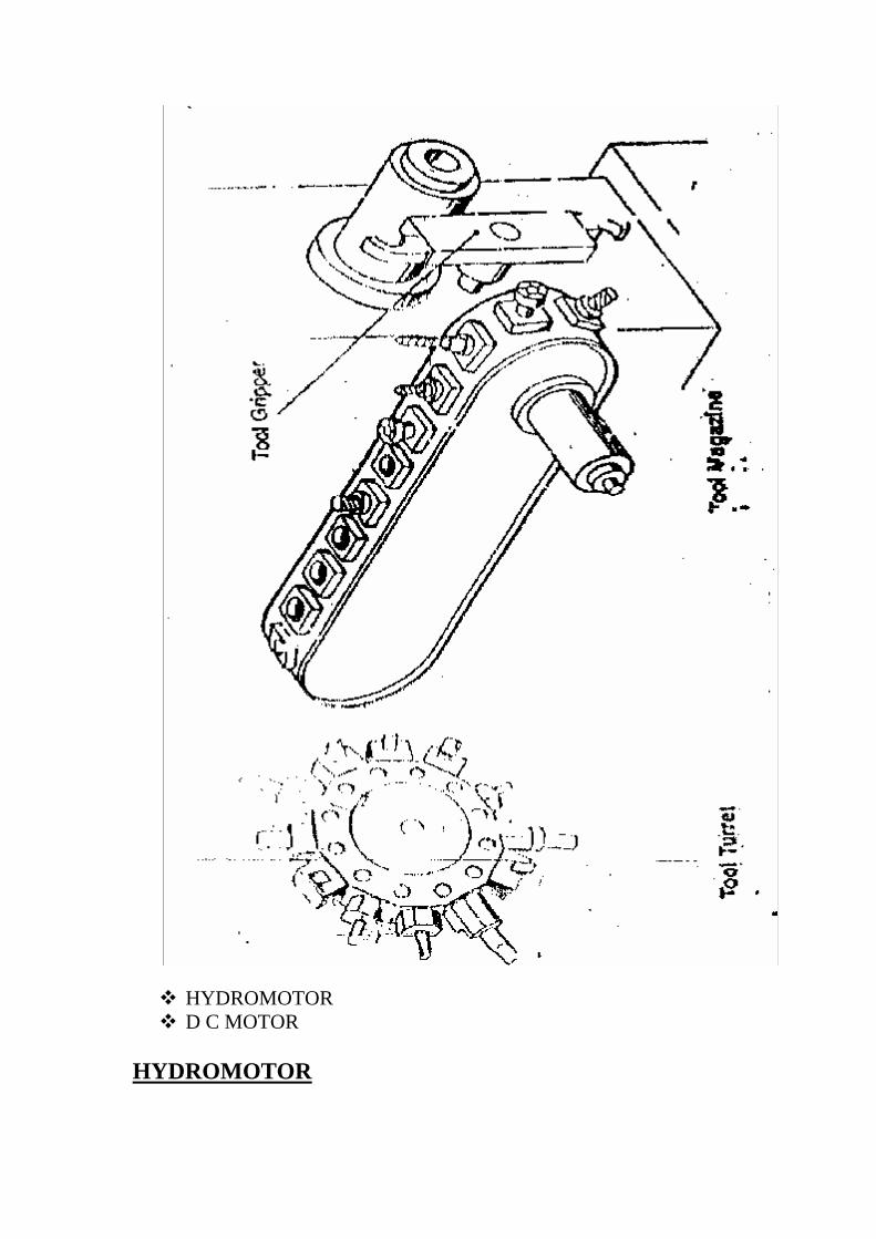
HYDROMOTOR D C MOTOR
HYDROMOTOR
HYDROMOTOR IS USED FOR THE ROTATION OF THE MAGAZINE.
MAGAZINE MOVES IN RAPID ONE TOOL AHEAD (SENSED BY PROXIMITY SWITCH)
MAGAZINE CREEPS TO THE POSITION IN A VERY LOW SPEED (SENSED BY PROXIMITY SWITCH).
WHEN THE MAGAZINE IS IN POSITION, LOCATING PIN ENTERS THE HOLE IN THE MAGAZINE AND POSITIONS THE MAGAZINE ACCURATELY.
D C MOTOR CNC SYSTEM CONTROLS THE ROTATION OF THE MOTOR AND HOLDS THE MAGAZINE IN POSITION FOR THE TOOL CHANGING.
SPINDLE ORIENTATION AND TOOL HOLDER RELATION
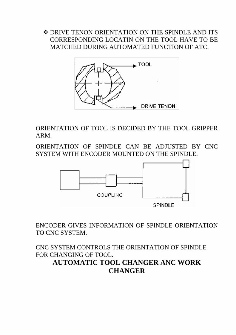
DRIVE TENON ORIENTATION ON THE SPINDLE AND ITS CORRESPONDING LOCATIN ON THE TOOL HAVE TO BE MATCHED DURING AUTOMATED FUNCTION OF ATC.
ORIENTATION OF TOOL IS DECIDED BY THE TOOL GRIPPER ARM.
ORIENTATION OF SPINDLE CAN BE ADJUSTED BY CNC SYSTEM WITH ENCODER MOUNTED ON THE SPINDLE.
ENCODER GIVES INFORMATION OF SPINDLE ORIENTATION TO CNC SYSTEM. CNC SYSTEM CONTROLS THE ORIENTATION OF SPINDLE FOR CHANGING OF TOOL.
AUTOMATIC TOOL CHANGER ANC WORK CHANGER

HYDRAULIC AND PNEUMATIC ELEMENTS OF CNC MACHINES
HYDRAULIC ELEMENTS
Hydraulic elements can be classified as : 1. Pressure developing elements or pumps 2. Control elements or valves. 3. Conveying elements or hose pipes and other pipe lines. 4. Hydraulic activators, i.e. cylinder, hydraulic motors etc. 5. Sealing elements i.e. piston seals, shaft seals and coves seals like O rings, U
seals, V seals etc. 6. Circuit devices like accumulators, pressure intensifiers. 7. Miscellaneous element like strainers filters, presure gauges, temperature
gauges. 8. Oil reservoirs. HYDRAULIC PUMPS Hydraulic pumps are used to convert mechanical power supplied from external sources to fluid power. All hydraulic pumps are positive displacement type which are classified as.
1. Vane pumps 2. Gear pump. 3. Piston pump. a) Axial piston type. b) Radial piston type. HYDRAULIC PUMPS Pumps are classified according to 1. Displacement 2. Pressure 3. Construction. 1) According to displacement again they are classified as a) Fixed displacement pumps. b) Variable displacement pumps. 2) According to pressure pumps are classified as a) Low pressure pumps. b) High pressure pumps. 3) According to construction, pumps are classified as a) Rotary pumps.
b) Piston pumps Gear pumps, vane pumps, lobe pumps and Screw pumps are called rotary pumps and radial piston pumps, Axis piston pumps, and piston pump with bent axis are called piston pumps.
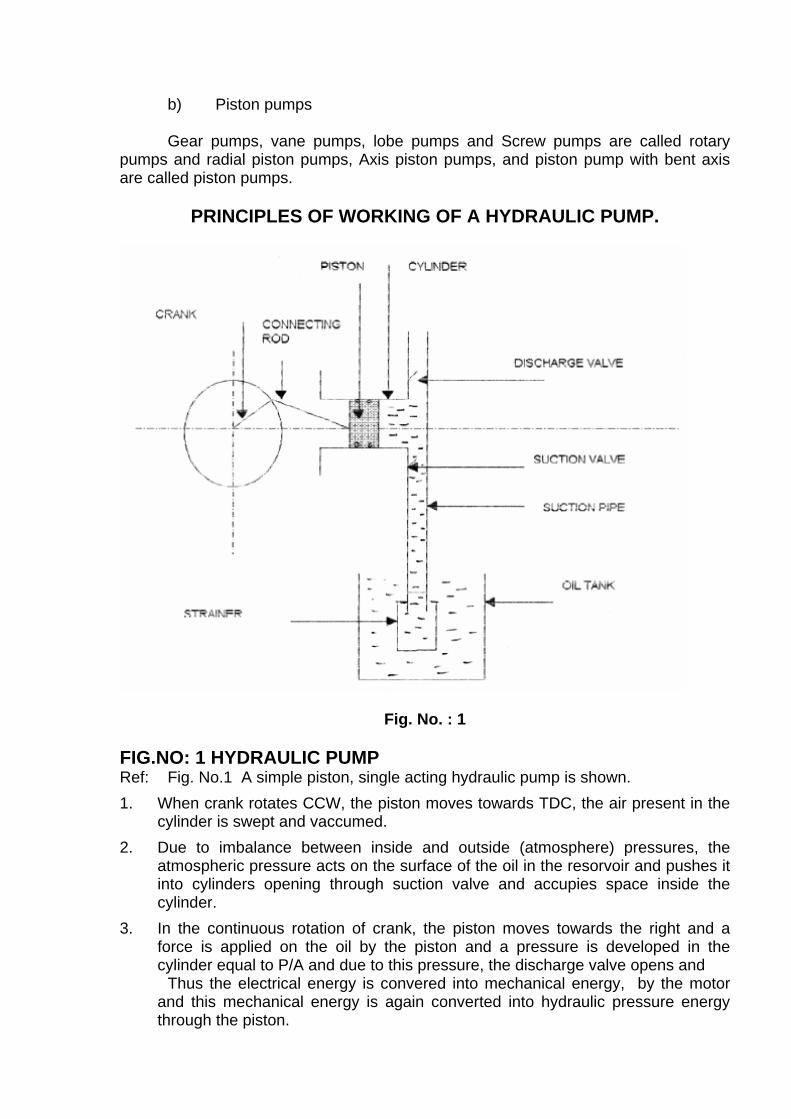
PRINCIPLES OF WORKING OF A HYDRAULIC PUMP.
Fig. No. : 1
FIG.NO: 1 HYDRAULIC PUMP Ref: Fig. No.1 A simple piston, single acting hydraulic pump is shown. 1. When crank rotates CCW, the piston moves towards TDC, the air present in the
cylinder is swept and vaccumed. 2. Due to imbalance between inside and outside (atmosphere) pressures, the
atmospheric pressure acts on the surface of the oil in the resorvoir and pushes it into cylinders opening through suction valve and accupies space inside the cylinder.
3. In the continuous rotation of crank, the piston moves towards the right and a force is applied on the oil by the piston and a pressure is developed in the cylinder equal to P/A and due to this pressure, the discharge valve opens and
Thus the electrical energy is convered into mechanical energy, by the motor and this mechanical energy is again converted into hydraulic pressure energy through the piston.
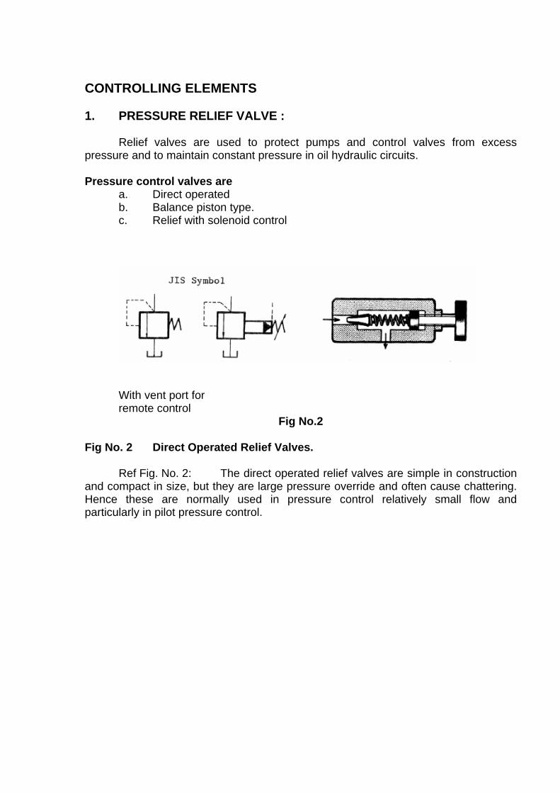
CONTROLLING ELEMENTS 1. PRESSURE RELIEF VALVE : Relief valves are used to protect pumps and control valves from excess pressure and to maintain constant pressure in oil hydraulic circuits. Pressure control valves are a. Direct operated b. Balance piston type. c. Relief with solenoid control
With vent port for remote control
Fig No.2
Fig No. 2 Direct Operated Relief Valves. Ref Fig. No. 2: The direct operated relief valves are simple in construction and compact in size, but they are large pressure override and often cause chattering. Hence these are normally used in pressure control relatively small flow and particularly in pilot pressure control.
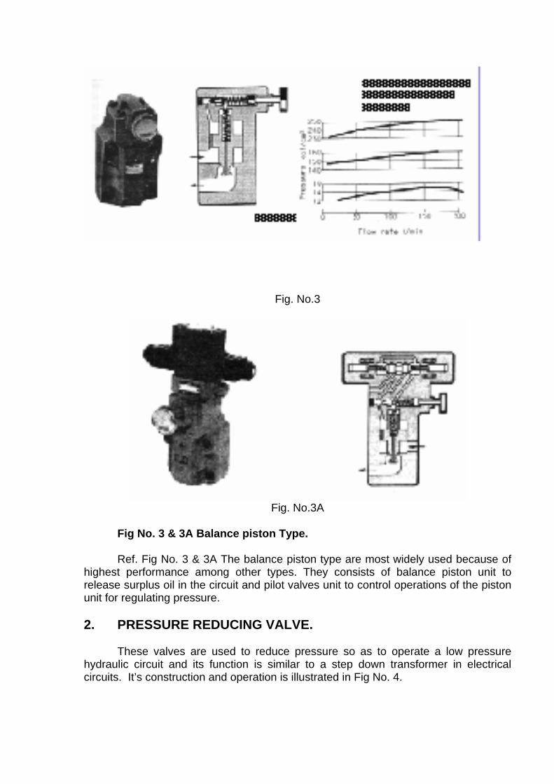
Fig. No.3
Fig. No.3A
Fig No. 3 & 3A Balance piston Type. Ref. Fig No. 3 & 3A The balance piston type are most widely used because of highest performance among other types. They consists of balance piston unit to release surplus oil in the circuit and pilot valves unit to control operations of the piston unit for regulating pressure. 2. PRESSURE REDUCING VALVE. These valves are used to reduce pressure so as to operate a low pressure hydraulic circuit and its function is similar to a step down transformer in electrical circuits. It’s construction and operation is illustrated in Fig No. 4.
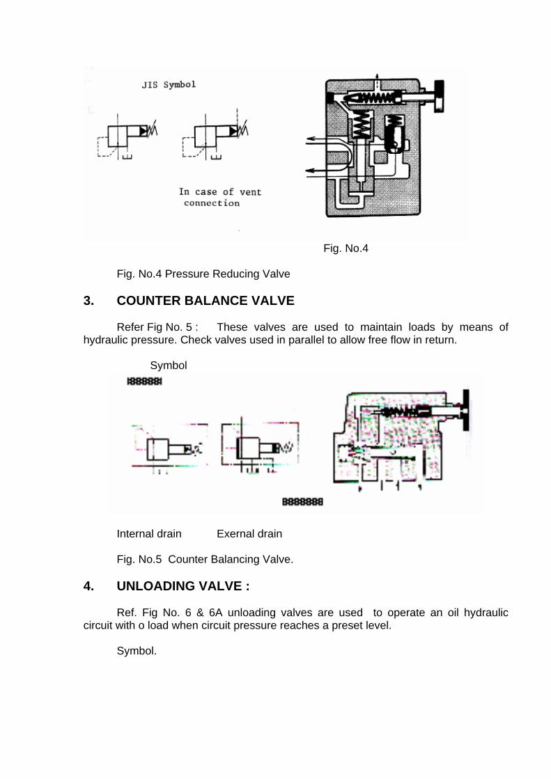
Fig. No.4
Fig. No.4 Pressure Reducing Valve 3. COUNTER BALANCE VALVE Refer Fig No. 5 : These valves are used to maintain loads by means of hydraulic pressure. Check valves used in parallel to allow free flow in return. Symbol
Internal drain Exernal drain Fig. No.5 Counter Balancing Valve. 4. UNLOADING VALVE : Ref. Fig No. 6 & 6A unloading valves are used to operate an oil hydraulic circuit with o load when circuit pressure reaches a preset level. Symbol.
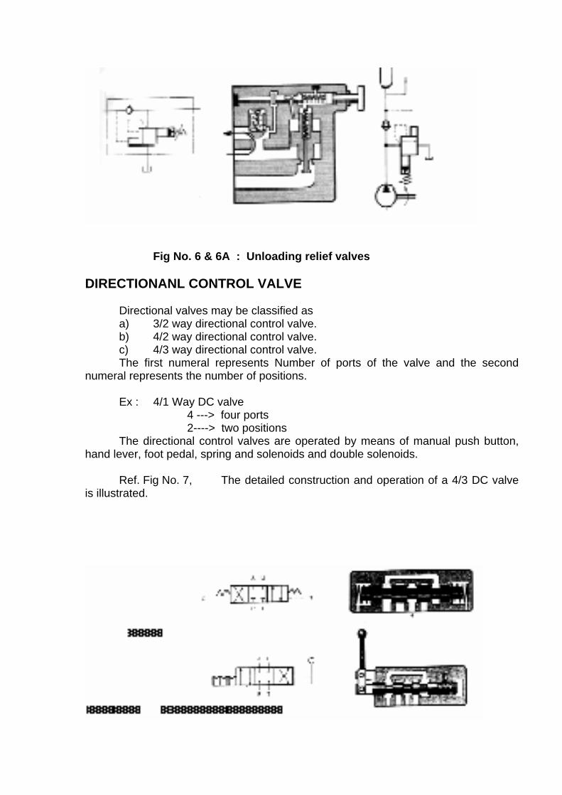
Fig No. 6 & 6A : Unloading relief valves DIRECTIONANL CONTROL VALVE Directional valves may be classified as a) 3/2 way directional control valve. b) 4/2 way directional control valve. c) 4/3 way directional control valve. The first numeral represents Number of ports of the valve and the second numeral represents the number of positions. Ex : 4/1 Way DC valve 4 ---> four ports 2----> two positions The directional control valves are operated by means of manual push button, hand lever, foot pedal, spring and solenoids and double solenoids. Ref. Fig No. 7, The detailed construction and operation of a 4/3 DC valve is illustrated.
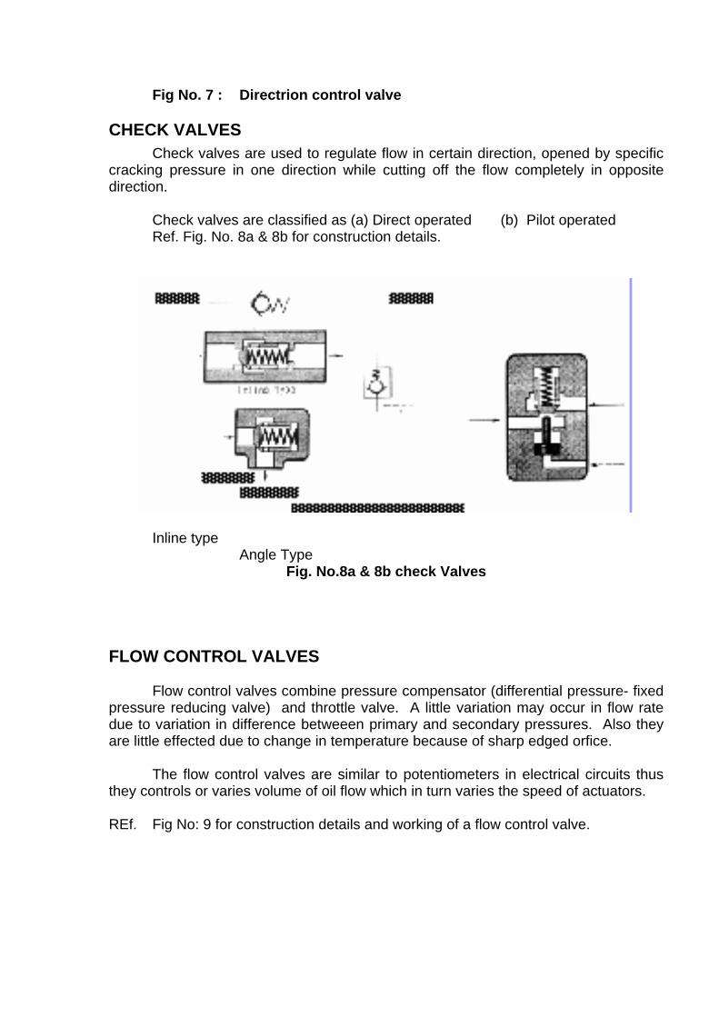
Fig No. 7 : Directrion control valve CHECK VALVES
Check valves are used to regulate flow in certain direction, opened by specific cracking pressure in one direction while cutting off the flow completely in opposite direction. Check valves are classified as (a) Direct operated (b) Pilot operated Ref. Fig. No. 8a & 8b for construction details.
Inline type Angle Type
Fig. No.8a & 8b check Valves
FLOW CONTROL VALVES Flow control valves combine pressure compensator (differential pressure- fixed pressure reducing valve) and throttle valve. A little variation may occur in flow rate due to variation in difference betweeen primary and secondary pressures. Also they are little effected due to change in temperature because of sharp edged orfice. The flow control valves are similar to potentiometers in electrical circuits thus they controls or varies volume of oil flow which in turn varies the speed of actuators. REf. Fig No: 9 for construction details and working of a flow control valve.
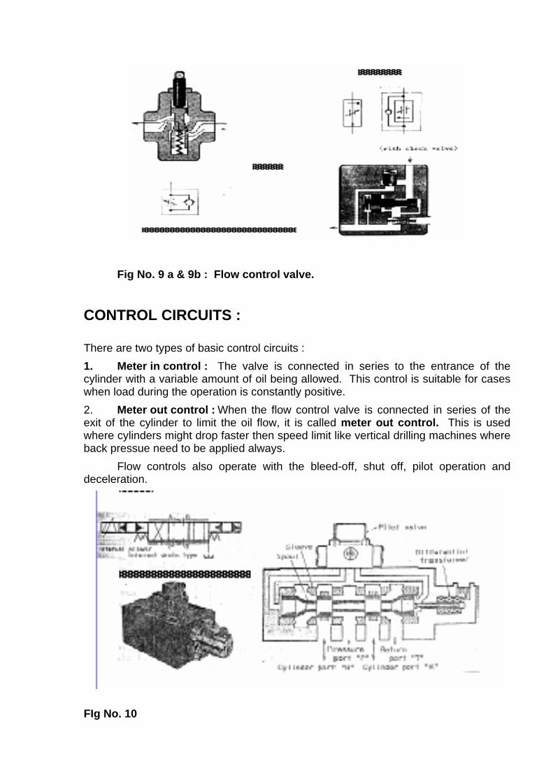
Fig No. 9 a & 9b : Flow control valve. CONTROL CIRCUITS : There are two types of basic control circuits : 1. Meter in control : The valve is connected in series to the entrance of the cylinder with a variable amount of oil being allowed. This control is suitable for cases when load during the operation is constantly positive. 2. Meter out control : When the flow control valve is connected in series of the exit of the cylinder to limit the oil flow, it is called meter out control. This is used where cylinders might drop faster then speed limit like vertical drilling machines where back pressue need to be applied always. Flow controls also operate with the bleed-off, shut off, pilot operation and deceleration.
FIg No. 10
Proportional valve : Ref. Fig No. 10 . These valves are designed to control a positionof spool in 4 way spool valves by means of pilot mechanism using a torque motor. Since spool opening area can be easily set by varying in input current, directional control and flow control can be easily done simultaneously. Hydraulic accumulators : Accumulators are use to store pressure and reduce hydraulic shock and are classified into : a) Weight type b) Biadders type. c) Piston type. Among the above the bladders type valves are most commony used in CNC machine tool and these are compact and responds effectively to the shocks. Pressure intensified: It is used to intensify pressure at the expense of some loss of hydraulic pressure. The two pistons are connected to same shaft. The larger piston drives the smaller piston and the pressure is intensified in the ratio of equal to the ratios of the areas of the larger and smaller pistons.
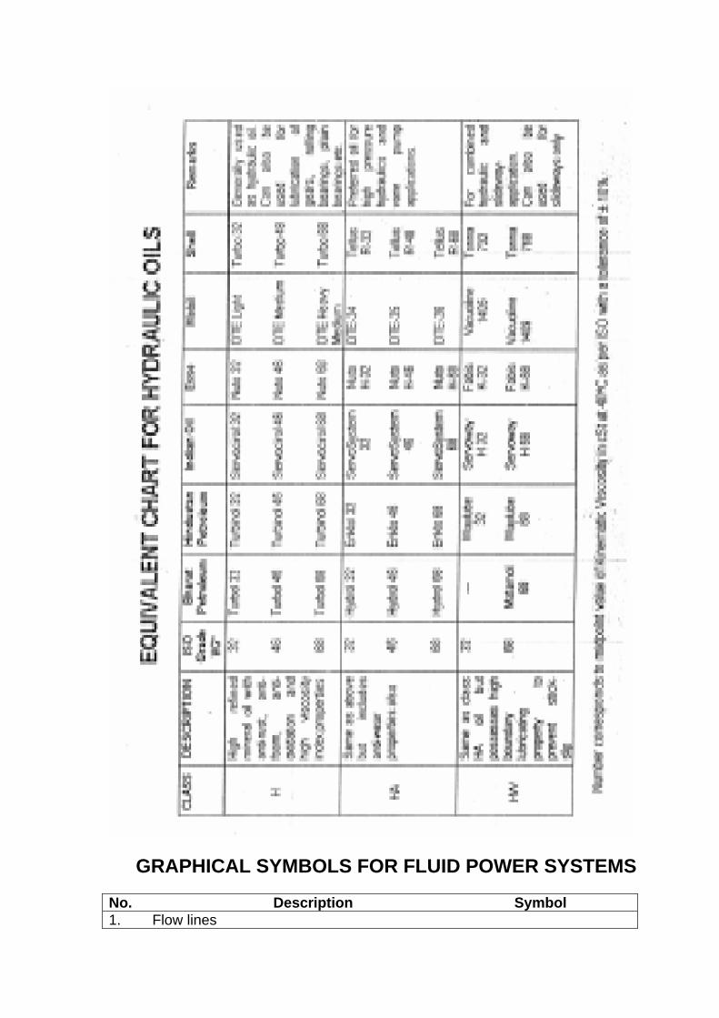
GRAPHICAL SYMBOLS FOR FLUID POWER SYSTEMS
No. Description Symbol 1. Flow lines

1.1. working line, return line and feed line 1.2 pilot control line 1.3 drain line 2. Miscellaneous symbols 2.1 flow line connection 2.2 spring 2.3 restriction 2.3.1 affected by viscosity
2.3.2 unaffected by viscosity
3. Pressure source :
3.1 hydraulic 3.2 pneumatic
4. Elecric motor
5. Heat engine
6. Flexible hose, usually connecting moving parts.
7 Power take-off
7.1 plugged
7.2 with take off line
8. Triangle 8.1 direction of hydraulic flow in one direction.
GRAPHICAL SYMBOLS FOR FLUID POWER SYSTEMS
No. Description Symbol
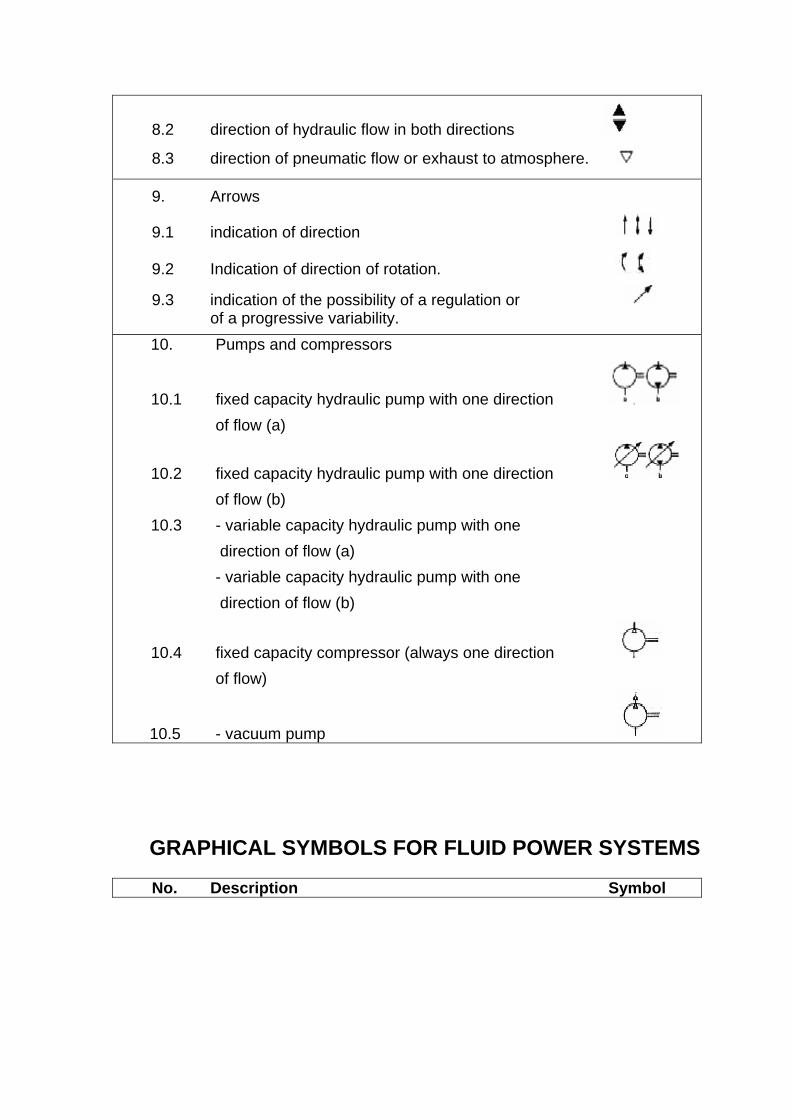
8.2 direction of hydraulic flow in both directions
8.3 direction of pneumatic flow or exhaust to atmosphere.
9. Arrows
9.1 indication of direction
9.2 Indication of direction of rotation.
9.3 indication of the possibility of a regulation or of a progressive variability. 10. Pumps and compressors
10.1 fixed capacity hydraulic pump with one direction of flow (a)
10.2 fixed capacity hydraulic pump with one direction of flow (b) 10.3 - variable capacity hydraulic pump with one direction of flow (a) - variable capacity hydraulic pump with one direction of flow (b)
10.4 fixed capacity compressor (always one direction of flow)
10.5 - vacuum pump
GRAPHICAL SYMBOLS FOR FLUID POWER SYSTEMS
No. Description Symbol
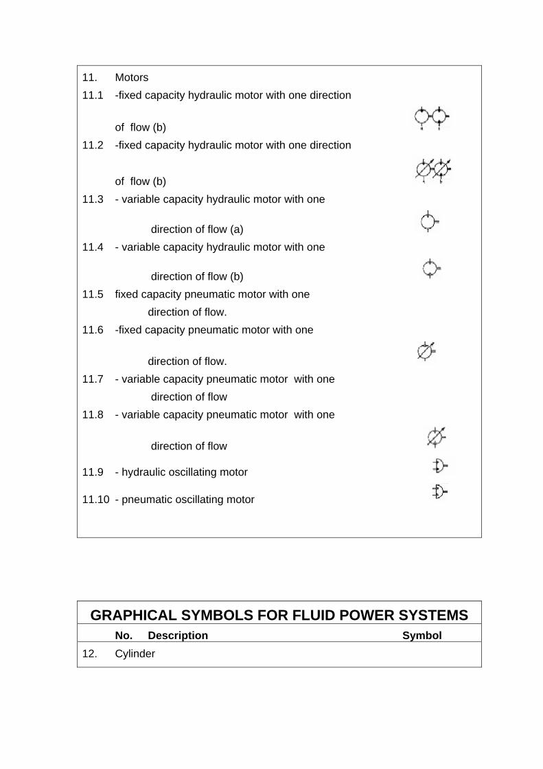
11. Motors 11.1 -fixed capacity hydraulic motor with one direction
of flow (b) 11.2 -fixed capacity hydraulic motor with one direction
of flow (b) 11.3 - variable capacity hydraulic motor with one
direction of flow (a) 11.4 - variable capacity hydraulic motor with one
direction of flow (b) 11.5 fixed capacity pneumatic motor with one direction of flow. 11.6 -fixed capacity pneumatic motor with one
direction of flow. 11.7 - variable capacity pneumatic motor with one direction of flow 11.8 - variable capacity pneumatic motor with one
direction of flow
11.9 - hydraulic oscillating motor
11.10 - pneumatic oscillating motor
GRAPHICAL SYMBOLS FOR FLUID POWER SYSTEMS No. Description Symbol 12. Cylinder
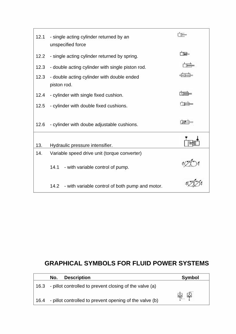
12.1 - single acting cylinder returned by an unspecified force
12.2 - single acting cylinder returned by spring.
12.3 - double acting cylinder with single piston rod.
12.3 - double acting cylinder with double ended piston rod.
12.4 - cylinder with single fixed cushion.
12.5 - cylinder with double fixed cushions.
12.6 - cylinder with doube adjustable cushions.
13. Hydraulic pressure intensifier. 14. Variable speed drive unit (torque converter)
14.1 - with variable control of pump.
14.2 - with variable control of both pump and motor.
GRAPHICAL SYMBOLS FOR FLUID POWER SYSTEMS
No. Description Symbol
16.3 - pillot controlled to prevent closing of the valve (a)
16.4 - pillot controlled to prevent opening of the valve (b)

17. Shuttle valve
18. Rapid exhaust valve
19. Pressure relief valve (safety valve)
19.1 - with remote pilot control
20. Sequence valve.
21. Pressure regulator or reducing valve.
22. Flow control valves.
22.1 - throttle valve.
22.1.1. - with mechanical control against a return spring (braking valve)
GRAPHICAL SYMBOLS FOR FLUID POWER SYSTEMS
No. Description Symbol
22.2 - flow control valve with fixed output.
22.3 - flow control valve with variable output.
23. Flow diving valve.
24. Shut-off valve.

25. Silencer
26. Reservoirs.
26.1 - with inlet pipe above fluid level.
26.2 - with inlet pipe below fluid level..
26.3 - with a header line.
27. Accumulators
28. Filter or strainer
29. Water-trap
29.1 - with manual control. 29.2 - Automatically drained.
GRAPHICAL SYMBOLS FOR FLUID POWER SYSTEMS
No. Description Symbol
30. Air dryer
31. Lubricator
32. Heater
33. Cooler

34. Temperature controller
35. Manual control
35.1 - general (without indication of control type)
35.2. - by push button.
35.3 -by lever
35.4 - by pedal 36. Mechanical control
36.1 - by plunger or tracer.
36.2 - spring
36.3 - by roller
GRAPHICAL SYMBOLS FOR FLUID POWER SYSTEMS
No. Description Symbol
36.4 - by roller, opening in one direction only
37. Electrical control.
37.1 - by solenoid.
37.2 - by electric motor.

38. Control by application or release of pressure.
38.1 - by application of pressure (direct acting). 38.2 - indirect control, pilot actuated by application
of pressure. 38.3 - indirect control, pilot actuated by release
of pressure.
39. Pressure gauge.
40. Thermometer
41. Flow meter
42. Integrating flow meter
43. Pressure electric switch. HINTS ON MAINTENANCE OF HYDRAULIC FLUID IN THE SYSTEM.
HYDRAULIC FLUID CHANGES: Good maintenance procedures make it mandatory to keep the hydraulic fluid clean. A daily / weekly or monthly log should be kept on the hydraulic fluid condition. No hard and fast rule can be established for changing the fluid because of the great variety of operating conditions. However, we do know that when filter elements are replaced frequently, service life of a system increases. Periodic testing of the fluid by the supplier is recommended to confirm suitability for continued use and to establish the correct fluid filter element replacement interval.
Some of the considerations affecting hydraulic fluid life are operating temperature, type of service, contamination levels, filtration, and the chemical composition of the fluid. Fluid recommendations : The fluids recommended by these bulletins give the assurance of adequate wear protection and excellent chemical stability under the most adverse operation conditions. On mobile applications, the viscosity grade of the fluid should be changed in spring and autumn as is done with automobile engines. Hydrostatic transmissions and control mechanisms may require a different viscosity fluid. Fluid requirements are normally outlined in the original equipment manufacturers operations and maintenance manuals. DRAINING THE SYSTEM : The system should be started and fluid heated before draining. This will lower the time it takes to drain the system and allow impurities suspended in the fluid to be removed. It is desirable to remove all fluid from the system. Bleeding of the fluid at the lowest point in the system will help in most cases. Systems which have accumulated deposits that were not removed during draining must be flushed with a light viscosity fluid. The fluid should contain a rust inhibitor to protect metal surfaces against rust formation after draining. When hydraulic fluid is added to replenish the system, it should be pumped through a 25-micron filter. If such a filter is not available, a funnel with a fine wire screen (200 mesh or finer) can be used. It is important that fluid be clean and free of all substances which will cause improper operation.
FLUID CONTAMINATION / AERATION - CAUSED AND EFFECTS CONTAMINATION A contamination system can be the result of several factors: system design inadequate, poor maintenance of the system, poor house keeping of the system and adverse operating conditions.
A. SYSTEM DESIGN INADEQUATE 1. Reservoirs which cannot be cleaned. 2. Breathers that permit abrasive, inherent in the atmosphere to enter the
system. 3. Poor cylinder packing design (no wiper to clean dirt from the piston rod). 4. Improper piston rod design (piston rods with poor water characteristics).

5. Improper valving (anti - cavitation checks omitted from cylinder circuits with rapid drop characteristics).
6. Failure to provide adequate filtration. B. POOR MAINTENANCE OF THE SYSTEM 1. Improper and unclean practices when adding fluid to the system. 2. Failure to clean breathers. 3. Failure to change pitted cylinder rods and worn cylinder packing.
4. Failure to use good cleanliness practices when changing system components.
5. Failure to change filter cartridges and / or fluid at proper intervals. 6. Failure to purge debris from the system after a pump failure. C. POOR HOUSE KEEPING OF THE SYSTEM. Surgical cleanliness is not required; however, ordinary clean practices during assembly will pay off in increased service life of the equipment. Excessive and improper use of pipe thread sealer on lines and gaskets in the system can cause pump failures. This is especially true when a type of sealer is used that hardens. Another source of contamination is fittings, hoses, and lines which are received from a vender uncapped. The use of brazed or welded fittings and unpicked steel plating can also contribute to the contamination D. ADVERSE OPERATING CONDITIONS From experience, we have found that machines used in a every industry atmosphere and in windy areas require special components. For example, heavy-duty breathers chrome plated piston rods, plus frequent changes of the filter cartridges are also required. EFFECTS OF CONTAMINATION Contamination affects all types of hydraulic equipment adversely. Precision high tolerance parts are very susceptible to the effects of contamination. Dirty fluid causes wear which accelerates leakage and the development of heat in a system. Heat lowers the lubricity of a hydraulic fluid and causes additional wear. If a hydraulic pump or motor should fail, the system becomes contaminated. Remove the unit for repair. The reservoir must be drained, flushed and cleaned. All hoses, lines, cylinders and valves should be inspected for wear and particles of the unit that failed. Flush all the components of the complete system to remove metallic particles. Replace filter elements. Dispose of the fluid remove from the system and fill the
reservoir with clean hydraulic fluid. Install a new or rebuilt unit and start-up the system. Allow the system to run for period of time to verify normal operation. Filter elements should be changed after 40 or 50 hours of operation. These guarantees that the system is essentially clean and free of any residue of the failed unit. AERATION (Air bubbles in the fluids)
Causes
The following are candidates for the format in of air in a system.
A. Leaking inlet lines.
B. Control valve ‘O” rings leaking.
C. Shaft seal leakage.
D. Leaking cylinder packing caused by cavitation cylinder.
E. Turbulence or sloshing in the reservoir.
F. Vortexing fluid in the reservoir.
G. Release of air suspended within the fluid.
EFFECTS
Aeration can be in many forms: large bubbles, foam or in various degrees of suspension. It usually causes pump noise (cavitation). Small bubbles cause extreme and rapid ring wear, with corresponding vane tip wear. Large bubbles cause vanes to collapse and pound. This pounding effect develops ripping in the ring and the ring will have a dull appearance. This is more apparent on straight vane rings which are hardened cast iron. With extreme aeration cases, the wear is so rapid that a ring and vanes can be destroyed with in an hour. In many cases, a large step will be worn in the ring contour at the pressure quadrant. When the step reaches a depth where the vane extends and locks, the vane and / or ring will break. Also, the shaft can break where it enters the rotor if the torque is great enough. CURES A. Leaking inlet Lines 1. Pipe threaded fittings can be porous. Use an approved type of pipe
thread sealer on all pipe threads.
2. If the pump inlet flange surface is rough, scored or mutilated, air leakage past the “O” ring seal can result.
With any of the above defects, air can be pulled to the system. B. CONTROL VALVE “O” RINGS LEAKING. “O” rings are used to seal against port leakage in many control valves. These seals can be checked by applying heavy grease around the part to be checked. If the noise stops, the trouble has been located and repair can initiated.
On systems which have been operating at excessive high temperatures, the “O” rings can harden and take a set. If this occurs, air leakage can result. This is true not only in pump, but also in the rest of the components of the system. Another factor enhancing air leakage is the actual fluid composition. Fluids which have high sulphur content tend to accelerate “O” ring hardness. This is normal operating temperature or a system is 90 degree above ambient. When operating temperatures are in excess of this value, trouble may result. Maximum operating temperatures should be checked at the pump outlet port. C. SHAFT SEAL LEAKAGE. Most vane pumps are internally drained. The shaft seal cavity is connected to the pump inlet. Excessively high inlet vacuums can cause air leakage at the shaft seal. The maximum vacuum measured at the pump inlet should not exceed five inches of mercury. Shaft misalignment can increase the probability of air leakage past the shaft seal. Universal jointed couplings or splined couplings can cause seal leakage if not properly aligned. Straight (direct) couplings should never be used. The use of the wrong type of tools can cause distortion or mutilation of a shaft seal at installation. The outer diameter of the shaft should be lightly polished, before installation to remove any burns or roughness in the area of the shaft seal. Shaft seals must be made of the correct material for a given application. A material that is not compatible with system fluid can deteriorate and result I leakage problem. D. LEAKING CYLINDER PACKING CAUSED BY CAVITATING CYLINDERS. On applications where a rapid raise and lower cycle is experienced, air can enter the system through a cylinder rod seal. Vacuums in excess of 20 inches of mercury have been recorded in systems without anti- cavitain check valves. This is enough to force dirt particles past the shaft seal into the system with the air. An anti-cavitation check will allow flow from the reservoir to enter the rod area of the cylinder during a vacuum condition. Anti-cavitation checks should always be used to prevent a high vacuum condition from developing This will lower the possibility of fluid contamination through the rod seal of a working cylinder. E TURBULENCE OR SLOSHING IN THE RESERVOIR. Return lines, if improperly located, can cause turbulence and aeration. A Plexiglas window should be placed in the prototype reservoir to study flow conditions. Return lines emptying above the fluid level cause bubbles to form in the system. Return lines should always be terminated below the fluid level. Vehicle movement can cause sloshing within the reservoir. Reservoir must be deep enough to prevent aeration. F. VORTEXING FLUID IN THE RESERVOIR.
If the fluid level in the reservoir is low and the inlet demand is great, a vortex condition can develop which pulls air into the pump inlet. In a hydraulic system, vortexing is normally the result of low fluid or poor reservoir design. One of the best ways of curing a vortex problem is to place an anti -cavitation plate over the outlet of the reservoir. This is a common piece of sheet metal at least 1/8 inch thick set over and above the outlet opening. This plate will allow flow into the outlet from a horizontal direction and effectively extends and enlarges the reservoir opening. This prevents the vortex condition from developing. G. RELEASE OF AIR SUSPENDED WITHIN THE FLUID. There is considerable air suspended in cold hydraulic fluid. As the fluid warms, air released into the system. A reduction of fluid pressure will also release air out of suspension. A simple relief valve poppet can create an orifice that increases velocity of the fluid and lowers its pressur. The reduced pressure condition releases air out of suspension into the system. Relief valves should be returned below the fluid level of the reservoir as far from the reservoir outlet as possible. This allows time for the air released by the relief valve to be removed before leaving the reservoir and entering the inlet area of the pump. In some cases, special line configurations are needed, or air bleed valves used, to remove air from the system. A special baffle made of 60-mesh screeen can be installed into the reservoir. This baffle should be positioned at a 30-degree angle in the reservoir so that inlet oil is above the screen and outlet oil is below the screen. The top of the screen should be below the reservoir fluid level far enough to prevent surface foam from coming in contact with the screen. Surface foam can penetrate through the screen into the outlet area. The screen baffle will eliminate all bubbles expect the very small ones from the fluid if designed properly.
GENERAL HYDRAULIC HINTS
GOOD ASSEMBLY PRACTICE - 1. Most important - cleanliness. 2. All openings in the reservoir should be sealed after cleaning. 3. No grinding or welding operations should be done in the area where hydraulic
components are being installed. 4. all cylinder, valve, pump and hose connection should be sealed and / or capped
until just prior to use. 5. Mineral spirits should be kept in safety containers. 6. Air hoses can be used to clean fittings and other system component. However,
the air supply must be filtered and dry to prevent contamination of the parts. 7. Examine pipe fittings and hose assemblies prior to use to be certain that burns,
dirt and / or scales are not present. 8. all pipe and tubing ends should be reamed to prevent restriction and turbulent
flow. 9. Do not use Teflon tape or compound on pipe thread or straight thread
connections. 10. When installing pumps or motors, always align coupling halves as closey as
possible, within 0.007 inch. 11. When using flexible couplings, follow the manufacture’s recommendations or
allow 1/32 to 1/16 inch. clearance between the coupling halves. 12. Do not drive couplings on pump or shafts. They should be a slip fit, or shrunk on
using hot oil. 13. Always use a dry spray-on lubricant on splines when installing. This prevents
wear and adds to the life of the splines. 14. When using double universal joint couplings, the shafts must be parallel and the
yokes must be in line. 15. When installing V-belt pulleys on pumps or motors, line up both pulleys as
closely as possible. Always install the pulleys with a minimum amount of overhang as close to the pump or motor face as possible. This increases bearing service life.
PIPES : Iron and steel pipes were the first kinds of pluming used to conduct fluid between system components. At present, pipe is the least expensive way to go when assembling a system. Seamless steel pipe is recommended for use in hydraulic systems with the pipe interior free of rust, scale and dirt. Early classifications of pipe wall thickness were: standard, extra heavy and double extra heavy. Today, pipes are classified by schedule number as specified by the American National Standards Institute (ANSI). The schedule numbers vary from 10 through 160. The larger the number, the heavier the wall thickness. The outer pipe diameter stays the same for a given pipe size while the inside opening becomes smaller as schedule number increases. A comparison of early classifications verses the ANSI classifications follow. Standard = schedule 40, extra heavy = schedule 80. The double extra heavy classification does not compare with a schedule number. However, the inside diameter of a double extra heavy pipe is approximately one half that of a schedule 160 pipe. In many cases, flanges are welded to the pipe ends and gaskets or “O” rings used to seal the fittings. Various pipe fittings are used to route the piping too and from each system components. These fittings can be threaded or welded in place as the need arises. Threaded connections are used in low-pressure applications where welded connections are used if high-pressure, high temperature, or where a severe mechanical load exists.
All piping should be secured with clamps to prevent vibration and excessive stress due to the weight of the fluid. Do not weld the clamps to the pipe as it may weaken the pipe and cause a stress crack to appear.
TUBING DO’S AND DON’TS 1. Don’t take heavy cuts on thin wall tubing with a tubing cutter. Use light cuts to
prevent deformation of the tube end. If the tube end is out of round, a greater possibilit of a poor connection exists.
2. Ream tubing to remove burrs only. DO NOT over ream tubing as it can weaken the connection.
3. Do not allow chips to accumulate in the tubing. They can be difficult to remove after bending.
4. Follow the manufacturers recommendations on the use of flaring tools. Don’t over-tighten the feed screw handle on a compression type-flaring tool. Improper use of a tool can cause washout and / or splitting of the flare connection.
5. Bend tubing instead of cutting and using a fitting. This reduces pressure drop and minimizes system losses. The minimum radius of a tubing bend should be at least three times the inside diameter of the tube. Larger bends are preferred.
6. Sketch the optimum tubing route before beginning the bending process. Be sure to use tubing with proper temper to prevent wrinkles and flattened bends.
7. Most flares are made by hand or power tools that swage the tube end over a split die. The standard flare angle is 37 degree from the centerline. For best results, heavy wall tubing should be cut, debared, flared and bend using power requirements.

CNC SYSTEMS
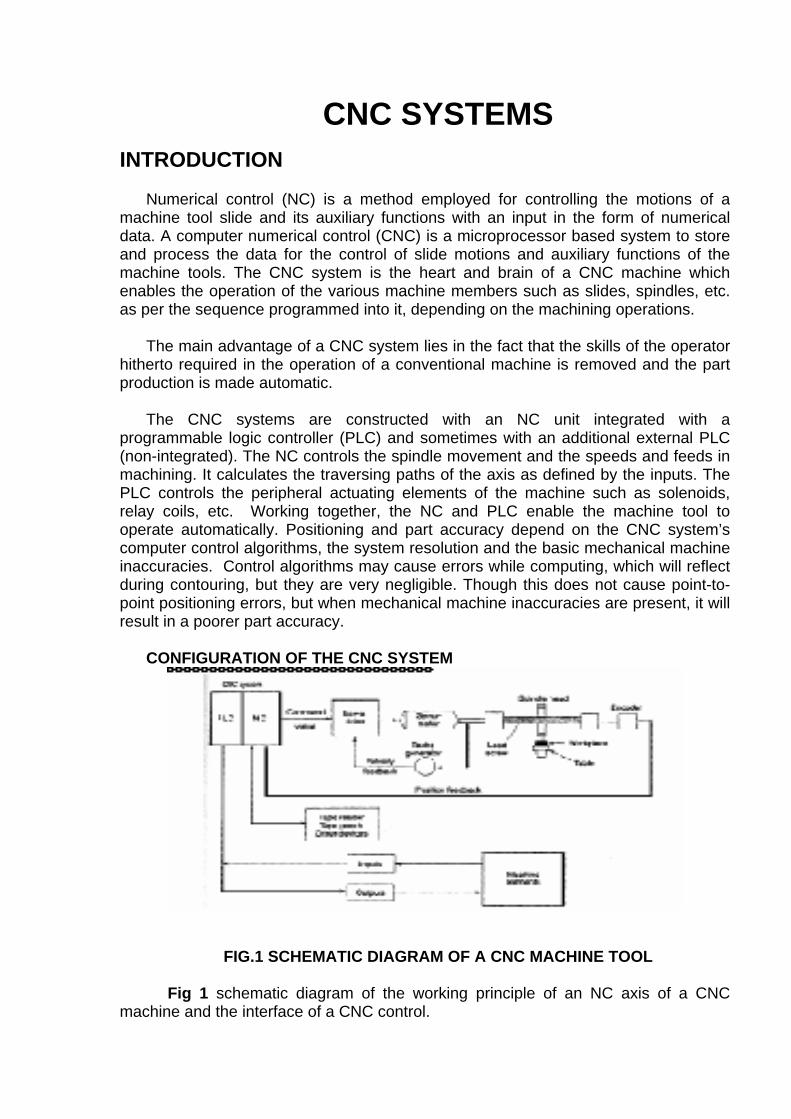
CNC SYSTEMS
INTRODUCTION Numerical control (NC) is a method employed for controlling the motions of a
machine tool slide and its auxiliary functions with an input in the form of numerical data. A computer numerical control (CNC) is a microprocessor based system to store and process the data for the control of slide motions and auxiliary functions of the machine tools. The CNC system is the heart and brain of a CNC machine which enables the operation of the various machine members such as slides, spindles, etc. as per the sequence programmed into it, depending on the machining operations.
The main advantage of a CNC system lies in the fact that the skills of the operator
hitherto required in the operation of a conventional machine is removed and the part production is made automatic.
The CNC systems are constructed with an NC unit integrated with a
programmable logic controller (PLC) and sometimes with an additional external PLC (non-integrated). The NC controls the spindle movement and the speeds and feeds in machining. It calculates the traversing paths of the axis as defined by the inputs. The PLC controls the peripheral actuating elements of the machine such as solenoids, relay coils, etc. Working together, the NC and PLC enable the machine tool to operate automatically. Positioning and part accuracy depend on the CNC system’s computer control algorithms, the system resolution and the basic mechanical machine inaccuracies. Control algorithms may cause errors while computing, which will reflect during contouring, but they are very negligible. Though this does not cause point-to-point positioning errors, but when mechanical machine inaccuracies are present, it will result in a poorer part accuracy.
CONFIGURATION OF THE CNC SYSTEM
FIG.1 SCHEMATIC DIAGRAM OF A CNC MACHINE TOOL Fig 1 schematic diagram of the working principle of an NC axis of a CNC
machine and the interface of a CNC control.
A CNC system basically consists of the following:
• Central processing unit (CPU)
• Servo-control unit
• Operator control panel Machine control panel.
• Other peripheral devices.
• Programmable logic controller
CENTRAL PROCESSING UNIT (CPU) The CPU is the heart and brain of a CNC system. It accepts the information stored
in the memory as part program. This data is decoded and transformed into specific position control and velocity control signals. It also oversees the movement of the control axis or spindle and whenever this does not match with the programmed values, a corrective action is taken.
All the compensations required for machine accuracies (like lead screw pitch error,
tool wear out, backlash, etc.) are calculated by the CPU depending upon the corresponding inputs made available to the system. The same will be taken care of during the generation of control signals for the axis movement. Also, some basic safety checks are built into the system through this unit and continuous necessary corrective actions will be provided by the CPU unit. Whenever the situation goes beyond control of the CPU, it takes the final action of shutting down the system and in turn the machine.
SPEED CONTROL UNIT
This unit acts in unison with the CPU for the movement of the machine axes. The
CPU sends the control signals generated for the movement of the axis to the servo-control unit and the servo-control unit converts these signals into a suitable digital or analog signal to be fed to a servo-drive for machine tool axis movement. This also checks whether machine tool axis movement is at the same speed as directed by the CPU. In case any safety conditions related to the axis are overruled during movement or otherwise they are reported to the CPU for corrective action.
SERVO-CONTROL UNIT The decoded position and velocity control signals generated by the CPU for the
axis movement forms the input to the servo-control unit. This unit in turn generates suitable signals as command values. The command values are converted by the servo-drive unit, which are interfaced with the axes and the spindle motors.
The servo-control unit receives the position feedback signals for the actual
movement of the machine tool axes from the feedback devices (like linear scales, rotary encoders, resolvers, etc.). The velocity feedbacks are generally obtained through tacho generators. The feedback signals are passed on to the CPU for further
processing. Thus, the servo-control unit performs the data communication between the machine tool and the CPU.
The actual movement of the slides on the machine tool is achieved through servo
drives. The amount of movement and the rate of movement are controlled by the CNC system depending upon the type of feedback system used, i.e. closed-loop or open-loop system. CLOSED-LOOP SYSTEM
The closed-loop system is characterised by the presence of feedback. In this
system, the CNC system sends out commands for movement and the result is continuously monitored by the system through various feedback devices. There are generally two types of feedback to a CNC system-position feedback and velocity feedback.
POSITION FEEDBACK
A closed-loop system, regardless of the type of feedback device, will constantly try
to achieve and maintain a given position by self-correcting. As the slide of the machine tool moves, its movement is fed back to the CNC system for determining the position of the slide to decide how much is yet to be traveled and also to decide whether the movement is as per the commanded rate. If the actual rate is not as per the required rate, the system tries to correct it. In case this is not possible, the system declares a fault and initiates action for disabling the drives and if necessary switches off the machine.
VELOCITY FEEDBACK
Velocity feedback must be present along with the position feed-back
whenever CNC systems are used for contouring, in order to produce correct interpolations and also specified acceleration and deceleration velocities. The tacho generator used for velocity feedback is normally connected to the motor and it rotates whenever the motor rotates, thus giving an analog output proportional to the speed of the motor. This analog voltage is taken as speed feedback by the servo-controller and swift action is taken by the controller to maintain the speed of the motor within the required limits.
OPEN LOOP SYSTEM
The open-loop system lacks feedback, In this system, the CNC system sends
out signals for movement but does not check whether actual movement is taking place or not. Stepper motors are used for actual movement and the electronics of these stepper motors is run on digital pulses from the CNC system. Since system controllers have no access to any real time information about the system performance, they cannot counteract disturbances appearing during the operation. They can be utilised in point-to-point system, where loading torque on the axial motors is low and almost constant.
SERVO-DRIVES The servo-drive receives signals from the CNC system and transforms it into
actual movement on the machine. The actual rate of movement and direction depend upon the command signal from the CNC system. There are various types of servo-drives, viz. DC drives, AC drives and stepper motor drives. A servo-drive consists of two parts, namely, the motor and the electronics for driving the motor. OPERATOR CONTROL PANEL
The operator control panel provides the user interface to facilitate a two-
way communication between the user, CNC system and the machine tool. This consists of two parts:
• Video display unit • Keyboard
VIDEO DISPLAY UNIT (VDU)
The VDU displays the status of the various parameters of the CNC system and
the machine tool. It displays all current information such as:
• Complete information of the block currently being executed.
• Actual position value, set or actual difference, current feed rate, spindle speed.
• Active G functions & miscellaneous functions. • Main program number, subroutine number.
• Display of all entered data, user programs user data, machine data, etc.
• Alarm messages in plain text.
• Soft key designations. In addition to a CRT, a few LEDs are generally provided to indicate important
operating modes and status.
KEYBOARD A keyboard is provided for the following purposes:
• Editing of part programs, tool data, machine parameters. • Selection of different pages for viewing. • Selection of operating modes e.g manual data input, jog, etc. • Selection of feed rate override and spindle speed override. • Execution of part programs. • Execution of other tools functions.
MACHINE CONTROL PANEL (MCP)
It is the direct interface between the operator and the NC system, enabling the operation of the machine through the CNC system.
During program execution, the CNC controls the axis motion, spindle function or tool function on a machine tool, depending upon the part program stored in the memory. Prior to the starting of the machining process, machine should first be prepared with some specific tasks like,
• Establishing a correct reference point
• Loading the system memory with the required part program.
• Loading and checking of tool offsets, zero offsets, etc.
For these tasks, the system must be operated in a specific operating mode so that these preparatory functions can be established. MODES OF OPERATION Generally, the CNC systems can be operated in the following modes:
• Manual mode
• Manual data input (MDI) mode
• Automatic mode
• Reference mode
• Input mode • Output mode, etc.
Manual Mode: In this mode, movement of a machine slide can be carried out
manually by pressing the particular jog buttons (positive or negative). The slide (axis) is selected through an axis selector switch or through individual switches (e.g., X+, X-, Y+, Y-, Z+, Z-, etc.). The feed rate of the slide movement is prefixed. Some CNC systems allow the axis to be jogged at a high feed rate also. The axis movement can also be achieved manually using a hand wheel interface instead of jog buttons. In this mode slides can be moved in two ways:
• Continuous. • Incremental.
Continuous Mode: In this mode, the slide will move as long as the jog button is pressed.
INCREMENTAL MODE: The slide will move through a fixed distance, which is selectable. Normally systems allow jogging of axes in 1,10,100,1000,10000 increments. Axis movement is at a prefixed feed rate. It is initiated by pressing the proper Jog+ or Jog- key and will be limited to the number of increments selected even if the Jog button Is continuously pressed. For subsequent movements the jog button has to be reloaded and once again pressed.
Manual Data Input (MDI) Mode: In this mode the following operations can be performed:
• Building a new part program.
• Editing or deleting of part programs stored in system memory.
• Entering or editing or deleting of:
• Tool offsets (TO)
• Zero offsets (ZO)
• Test Data, etc.
TEACH-IN
Some systems allow direct manual input of a program block and execution of the
same. The blocks thus executed can be checked for correctness of dimensions and consequently transferred into the program memory as part program.
PLAYBACK
In setting up modes like jog or incremental, the axis can be traversed either
through the direction keys or via the electronic hand wheel, and the end position can be transferred into the system memory as command values. But the required feed rates, switching functions and other auxiliary functions have to be added to the part program in program editing mode.
Thus, teach-in or playback operating method allows a program to be created
during the first component prove out.
AUTOMATIC MODE(AUTO AND SINGLE BLOCK) In this mode the system allows the execution of a part program continuously. The
part program is executed block by block. While one block is being executed, the next block is read by the system, analysed and kept ready for execution. Execution of the program can be one block after another automatically or the system will execute a block, stop the execution of the next block till it is initiated to do so (by pressing the start button). Selection of part program execution continuously (Auto), or one block at a time (Single Block) is done through the machine control panel.
Many systems allow blocks (single or multiple) to be retraced in the opposite
direction. Block retrace is allowed only when a cycle stop state is established, Part program execution can be resumed and its execution begins with the retraced block. This is useful for tool inspection or in case of tool breakage.
Program start can be affected at any block in the program, through the BLOCK
SEARCH facility.
REFERENCE MODE Under this mode the machine can be referenced to its home position so that all the
compensations (e.g. pitch error compensation) can be properly applied. Part programs are generally prepared in absolute mode with respect to machine zero. Many CNC
systems make it compulsory to reference the slides of the machine to their home positions before a program is executed while others make it optional.
INPUT MODE AND OUTPUT MODE (I/O MODE)
In this mode, the part programs, machine set-up data, tool offsets, etc. can be
loaded/ unloaded into/from the memory of the system from external devices like programming units, magnetic cassettes or floppy discs, etc. During data input, some systems check for simple errors (like parity, tape format, block length, unknown characters, program al-ready present in the memory, etc.). Transfer of data is done through a RS232C or RS422C port.
PROGRAMMABLE LOGIC CONTROLLER (PLC)
A PLC matches the NC to the machine. PLCs were basically introduced as
replacement for hard-wired relay control panels. They were developed to be re-programmed without hardware changes when requirements were altered and thus are re-usable. PLCs are now available with increased functions, more memory and larger input/output capabilities.
In the CPU, all the decisions are made relative to controlling a machine or a
process. The CPU receives input data, performs logical decisions based upon stored programs and drives the outputs. Connections to a computer for hierarchical control are done via the CPU.
The I/O structure of PLC is one of their major strengths. The inputs can be push
buttons, limit switches, relay contacts, analog sensors, selector switches, thumb wheel switches, proximity sensors, pressure switches, float switches, etc. The outputs can be motor starters, solenoid valves, piston valves, relay coils, indicator lights, LED displays etc.
INTERFACING
Interconnecting the individual elements of both the machine and the CNC system
using cables and connectors is called interfacing. Proper grounding in electrical installations is most essential. This reduces the
effects of interference and guards against electronic shocks to personnel. It is also essential to properly protect the electronic equipment.
Cable wires of sufficiently large cross-sectional area must be used. Even though
proper grounding reduces the effect of electrical interference, signal cables require additional protection. This is generally attained by using shielded cables. All the cable shields must be grounded at control only, leaving the other end free. Other noise reduction techniques include using suppression devices, proper cable separation, ferrous metal wire ways, etc. Electrical enclosures should be designed to provide proper ambient conditions for the controller. Power supply to the controller should match with the supplier’s specifications.

MONITORING In addition to the care taken by the machine tool builder during design and
interfacing, basic control also includes constantly active monitoring functions. This is on order to identify faults in the NC, the interface control and the machine at an early stage to prevent damages occurring to the work piece, tool or machine. If a fault occurs, first the machining sequence is interrupted, the drives are stopped, the cause of the fault is stored and then displayed as an alarm. At the same time, the PLC is informed that an NC alarm exists. In Hinumerik CNC system, for example, the following can be monitored:
• Read-in
• Format
• Measuring circuit cables
• Position encoders and drives
• Contour
• Spindle speed
• Enable signals
• Voltage
• Temperature
• Microprocessors
• Data transfer between operator control
• Transfer between NC and PLC
• Change of status of buffer battery
• System program memory
• User program memory
• Serial Interfaces
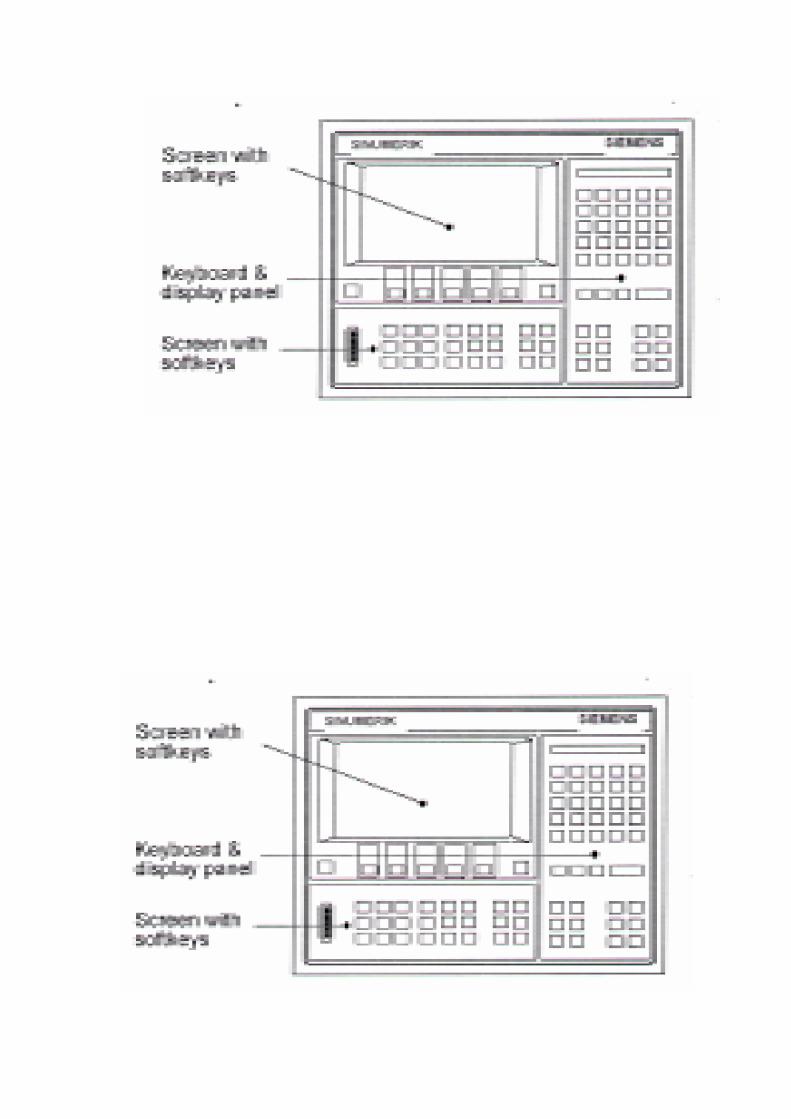

BATTERY REPLACEMENT IN SINUMERIK 810 CNC SYSTEM
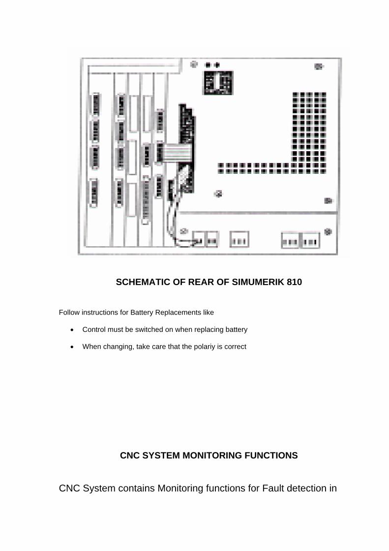
SCHEMATIC OF REAR OF SIMUMERIK 810
Follow instructions for Battery Replacements like
• Control must be switched on when replacing battery
• When changing, take care that the polariy is correct
CNC SYSTEM MONITORING FUNCTIONS
CNC System contains Monitoring functions for Fault detection in

NC
The interface control
Machine
Monitoring Functions exist in following Areas :
Format
Reading in
Measuring Circuit Cables
Encoders and Drives
Spindle Speed
Contour
Voltage
Microprocessors
Enable Signals
Serial Interfaces
Voltage level of the Back-up Battery
Transfer between NC and PLC
System program memory
User Program Memory
EXAMPLE OF ALARM WITH ALARM DESCRIPTION
Alarm No. : 2000
Alarm Text : “Emergency Stop” Reason : The EMERGENCY STOP signal is output from the PLC to the NC
Effect : Inhibiting of NC START
- Operation is brought to a defined stop
- Servo Enable is Removed
- Follow up operation
Remedy : Check to see if the EMERGENCY STOP cam was traversed to, or if the EMERGENCY STOP switch was operated.
MACHINE PARAMETERS
Used to match CNC system to the machine tool
Entered in CNC System during interfacing
Reside in system memory
Entered thru’ parameter editor or downloaded thru’ serial link
EXAMPLES :
Dry Run, referencing, maximum feed rates
G codes assumed at power up
Pulse Evaluation
In position tolerances
Gain factors
Software limits
Safe Zone programming
Communication protocol
Drift compensation
Backlash compensation
Lead screw compensation

DRIVES
In a CNC machine tool there are three major groups of elements (a) Control and electronics (b) Electric drives (c) Mechanical elements (table, slide, tool holder, etc.)
In addition, there can be hydraulic and pneumatic systems, which are integrated with the CNC machine tool.
The primary function of the drive is to cause motion of the controlled machine tool
member (spindle, slide, etc.) to conform as closely as possible to the motion commands issued by the CNC system.
In metal cutting machines the metal is removed as a result of the movement of the
work piece and the cutting tool. In order to maintain a constant material removal rate, the spindle and the tool
movements have to be coordinated such that the spindle has a constant power and the slide has a constant torque.
Modern CNC machines is built with higher control accuracies. In order to ensure a
high degree of consistency in production, variable speed drives are necessary. With the developments in power electronics and microprocessor systems, variable
drive systems have been developed. These are smaller in size, very efficient, and highly reliable and meet all the stringent demands of the modern automatic machine tools.
——————————————————————————————————— Spindle motors Feed motors ——————————————————————————————————— DC shunt motor(separately excited) DC Servomotor Three phase ac induction motor AC Servomotor Stepper motor ———————————————————————————————————— An electric drive consists of a motor and its associated control electronics. Depending on their characteristics, machine tool drives can be classified as follows. • Spindle drives-(constant power)
• Feed drives-{constant torque)
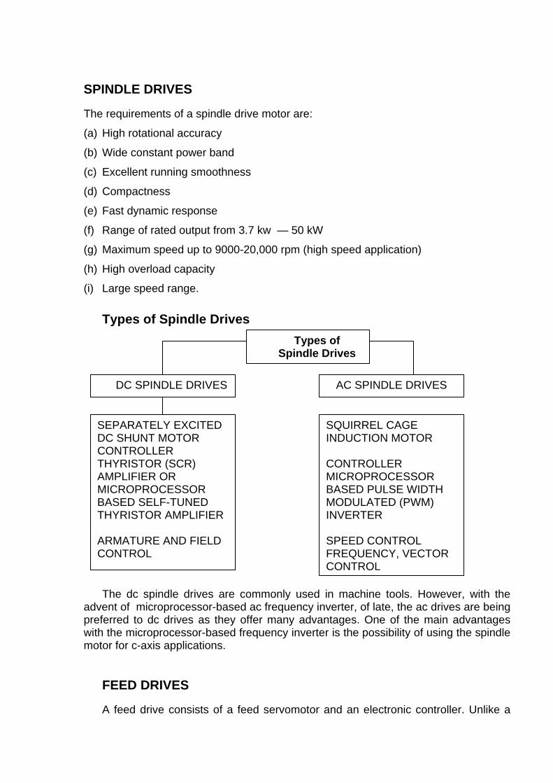
SPINDLE DRIVES The requirements of a spindle drive motor are:
(a) High rotational accuracy
(b) Wide constant power band
(c) Excellent running smoothness
(d) Compactness
(e) Fast dynamic response
(f) Range of rated output from 3.7 kw — 50 kW
(g) Maximum speed up to 9000-20,000 rpm (high speed application)
(h) High overload capacity
(i) Large speed range.
Types of Spindle Drives
Types of Spindle Drives
DC SPINDLE DRIVES AC SPINDLE DRIVES
SQUIRREL CAGE INDUCTION MOTOR CONTROLLER MICROPROCESSOR BASED PULSE WIDTH MODULATED (PWM) INVERTER SPEED CONTROL FREQUENCY, VECTOR CONTROL
SEPARATELY EXCITED DC SHUNT MOTOR CONTROLLER THYRISTOR (SCR) AMPLIFIER OR MICROPROCESSOR BASED SELF-TUNED THYRISTOR AMPLIFIER ARMATURE AND FIELD CONTROL
The dc spindle drives are commonly used in machine tools. However, with the advent of microprocessor-based ac frequency inverter, of late, the ac drives are being preferred to dc drives as they offer many advantages. One of the main advantages with the microprocessor-based frequency inverter is the possibility of using the spindle motor for c-axis applications.
FEED DRIVES A feed drive consists of a feed servomotor and an electronic controller. Unlike a
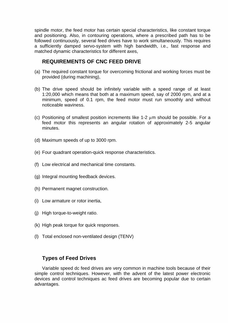
spindle motor, the feed motor has certain special characteristics, like constant torque and positioning. Also, in contouring operations, where a prescribed path has to be followed continuously, several feed drives have to work simultaneously. This requires a sufficiently damped servo-system with high bandwidth, i.e., fast response and matched dynamic characteristics for different axes,
REQUIREMENTS OF CNC FEED DRIVE
(a) The required constant torque for overcoming frictional and working forces must be provided (during machining),
(b) The drive speed should be infinitely variable with a speed range of at least
1:20,000 which means that both at a maximum speed, say of 2000 rpm, and at a minimum, speed of 0.1 rpm, the feed motor must run smoothly and without noticeable waviness.
(c) Positioning of smallest position increments like 1-2 µm should be possible. For a
feed motor this represents an angular rotation of approximately 2-5 angular minutes.
(d) Maximum speeds of up to 3000 rpm. (e) Four quadrant operation-quick response characteristics. (f) Low electrical and mechanical time constants. (g) Integral mounting feedback devices. (h) Permanent magnet construction. (i) Low armature or rotor inertia, (j) High torque-to-weight ratio. (k) High peak torque for quick responses. (l) Total enclosed non-ventilated design (TENV)
Types of Feed Drives Variable speed dc feed drives are very common in machine tools because of their
simple control techniques. However, with the advent of the latest power electronic devices and control techniques ac feed drives are becoming popular due to certain advantages.
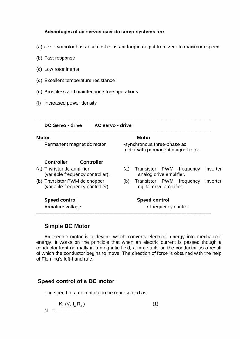
Advantages of ac servos over dc servo-systems are
(a) ac servomotor has an almost constant torque output from zero to maximum speed
(b) Fast response
(c) Low rotor inertia
(d) Excellent temperature resistance
(e) Brushless and maintenance-free operations
(f) Increased power density
———————————————————————————————————— DC Servo - drive AC servo - drive ———————————————————————————————————— Motor Motor Permanent magnet dc motor •synchronous three-phase ac
motor with permanent magnet rotor.
Controller Controller (a) Thyristor dc amplifier (a) Transistor PWM frequency inverter
(variable frequency controller). analog drive amplifier. (b) Transistor PWM dc chopper (b) Transistor PWM frequency inverter
(variable frequency controller) digital drive amplifier. Speed control Speed control Armature voltage • Frequency control ————————————————————————————————————
Simple DC Motor An electric motor is a device, which converts electrical energy into mechanical
energy. It works on the principle that when an electric current is passed though a conductor kept normally in a magnetic field, a force acts on the conductor as a result of which the conductor begins to move. The direction of force is obtained with the help of Fleming’s left-hand rule.
Speed control of a DC motor
The speed of a dc motor can be represented as K1 (Va-Ia Ra ) (1) N = ——————
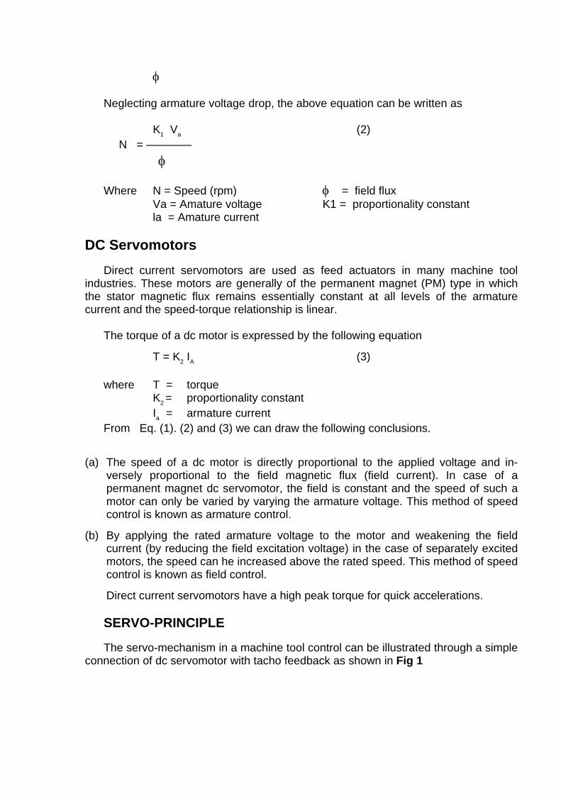
φ Neglecting armature voltage drop, the above equation can be written as K1 Va (2) N = ———— φ Where N = Speed (rpm) φ = field flux Va = Amature voltage K1 = proportionality constant la = Amature current
DC Servomotors Direct current servomotors are used as feed actuators in many machine tool
industries. These motors are generally of the permanent magnet (PM) type in which the stator magnetic flux remains essentially constant at all levels of the armature current and the speed-torque relationship is linear.
The torque of a dc motor is expressed by the following equation
T = K2 IA (3) where T = torque K2 = proportionality constant Ia = armature current From Eq. (1). (2) and (3) we can draw the following conclusions.
(a) The speed of a dc motor is directly proportional to the applied voltage and in-versely proportional to the field magnetic flux (field current). In case of a permanent magnet dc servomotor, the field is constant and the speed of such a motor can only be varied by varying the armature voltage. This method of speed control is known as armature control.
(b) By applying the rated armature voltage to the motor and weakening the field current (by reducing the field excitation voltage) in the case of separately excited motors, the speed can he increased above the rated speed. This method of speed control is known as field control.
Direct current servomotors have a high peak torque for quick accelerations. SERVO-PRINCIPLE The servo-mechanism in a machine tool control can be illustrated through a simple
connection of dc servomotor with tacho feedback as shown in Fig 1
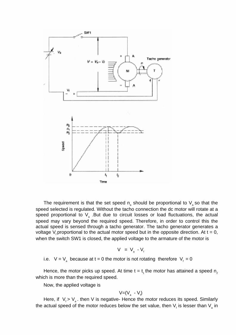
The requirement is that the set speed na should be proportional to Va so that the
speed selected is regulated. Without the tacho connection the dc motor will rotate at a speed proportional to Va .But due to circuit losses or load fluctuations, the actual speed may vary beyond the required speed. Therefore, in order to control this the actual speed is sensed through a tacho generator. The tacho generator generates a voltage Vf proportional to the actual motor speed but in the opposite direction. At t = 0, when the switch SW1 is closed, the applied voltage to the armature of the motor is
V = Va - Vf
i.e. V = Va because at t = 0 the motor is not rotating therefore Vf = 0 Hence, the motor picks up speed. At time t = t1 the motor has attained a speed n2
which is more than the required speed. Now, the applied voltage is
V=(Va - Vf) Here, if Vf > Va . then V is negative- Hence the motor reduces its speed. Similarly
the actual speed of the motor reduces below the set value, then Vf is lesser than Va in
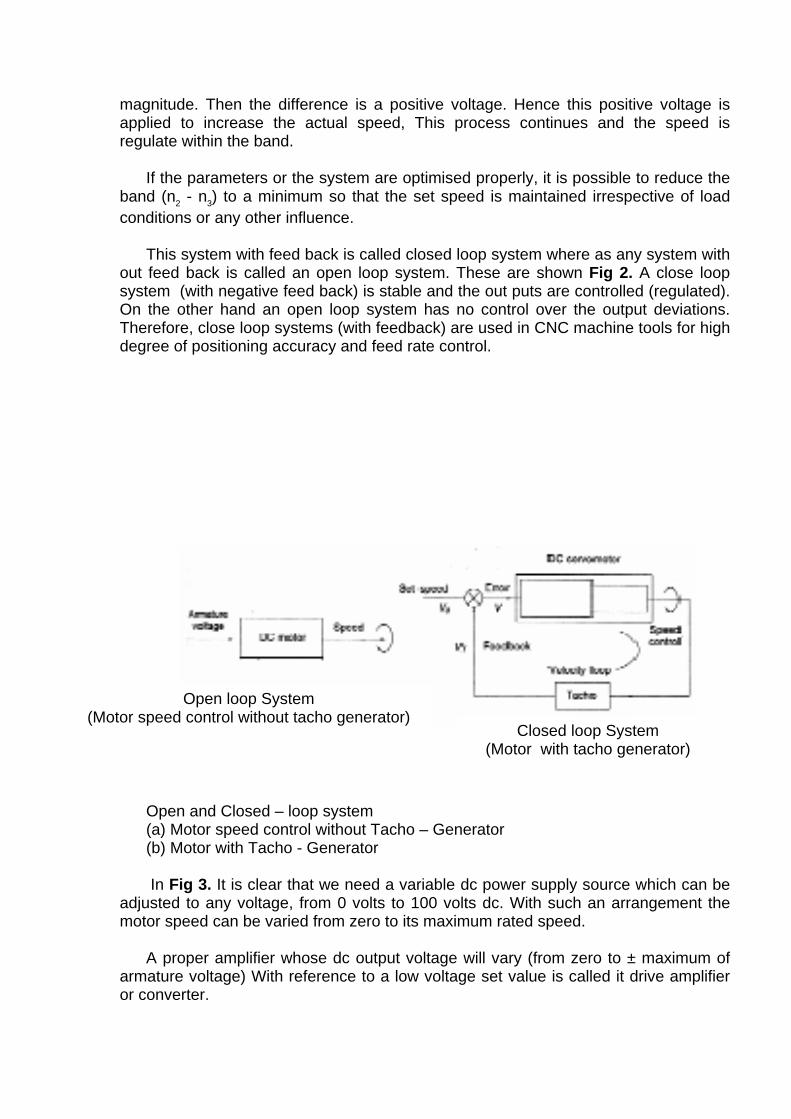
magnitude. Then the difference is a positive voltage. Hence this positive voltage is applied to increase the actual speed, This process continues and the speed is regulate within the band.
If the parameters or the system are optimised properly, it is possible to reduce the
band (n2 - n3) to a minimum so that the set speed is maintained irrespective of load conditions or any other influence.
This system with feed back is called closed loop system where as any system with
out feed back is called an open loop system. These are shown Fig 2. A close loop system (with negative feed back) is stable and the out puts are controlled (regulated). On the other hand an open loop system has no control over the output deviations. Therefore, close loop systems (with feedback) are used in CNC machine tools for high degree of positioning accuracy and feed rate control.
Open loop System (Motor speed control without tacho generator)
Closed loop System (Motor with tacho generator)
Open and Closed – loop system (a) Motor speed control without Tacho – Generator (b) Motor with Tacho - Generator In Fig 3. It is clear that we need a variable dc power supply source which can be
adjusted to any voltage, from 0 volts to 100 volts dc. With such an arrangement the motor speed can be varied from zero to its maximum rated speed.
A proper amplifier whose dc output voltage will vary (from zero to ± maximum of
armature voltage) With reference to a low voltage set value is called it drive amplifier or converter.
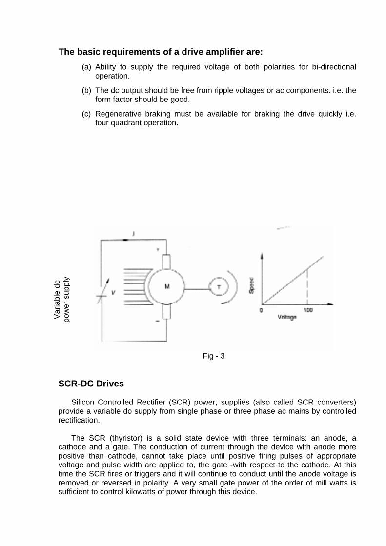
The basic requirements of a drive amplifier are: (a) Ability to supply the required voltage of both polarities for bi-directional
operation.
(b) The dc output should be free from ripple voltages or ac components. i.e. the form factor should be good.
(c) Regenerative braking must be available for braking the drive quickly i.e. four quadrant operation.
Var
iabl
e dc
po
wer
sup
ply
Fig - 3
SCR-DC Drives Silicon Controlled Rectifier (SCR) power, supplies (also called SCR converters)
provide a variable do supply from single phase or three phase ac mains by controlled rectification.
The SCR (thyristor) is a solid state device with three terminals: an anode, a
cathode and a gate. The conduction of current through the device with anode more positive than cathode, cannot take place until positive firing pulses of appropriate voltage and pulse width are applied to, the gate -with respect to the cathode. At this time the SCR fires or triggers and it will continue to conduct until the anode voltage is removed or reversed in polarity. A very small gate power of the order of mill watts is sufficient to control kilowatts of power through this device.
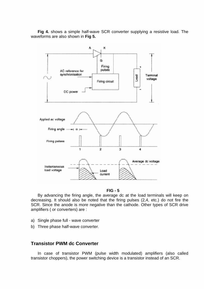
Fig 4. shows a simple half-wave SCR converter supplying a resistive load. The
waveforms are also shown in Fig 5.
FIG - 5 By advancing the firing angle, the average dc at the load terminals will keep on
decreasing. It should also be noted that the firing pulses (2,4, etc.) do not fire the SCR. Since the anode is more negative than the cathode. Other types of SCR drive amplifiers ( or converters) are :
a) Single phase full - wave converter b) Three phase half-wave converter.
Transistor PWM dc Converter
In case of transistor PWM (pulse width modulated) amplifiers (also called
transistor choppers), the power switching device is a transistor instead of an SCR.
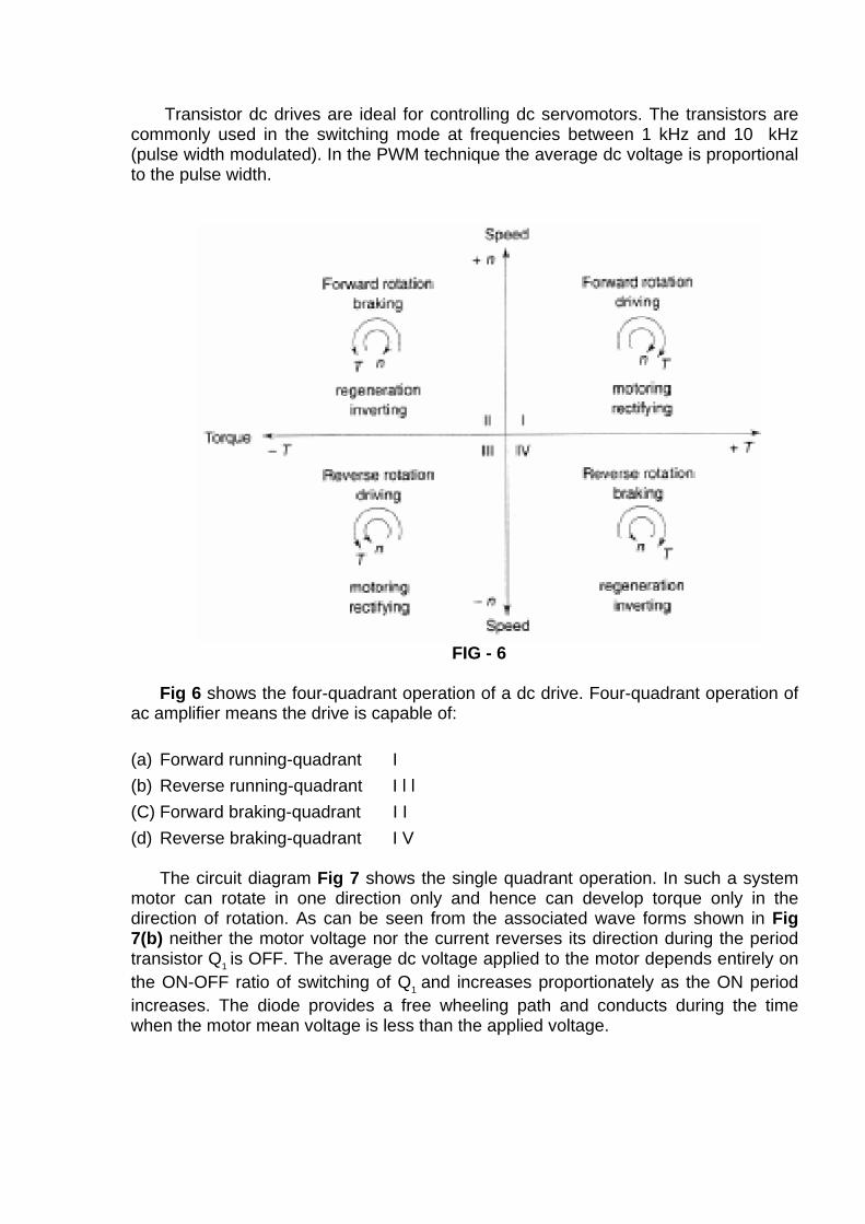
Transistor dc drives are ideal for controlling dc servomotors. The transistors are commonly used in the switching mode at frequencies between 1 kHz and 10 kHz (pulse width modulated). In the PWM technique the average dc voltage is proportional to the pulse width.
FIG - 6
Fig 6 shows the four-quadrant operation of a dc drive. Four-quadrant operation of
ac amplifier means the drive is capable of:
(a) Forward running-quadrant I (b) Reverse running-quadrant I l l (C) Forward braking-quadrant I I (d) Reverse braking-quadrant I V
The circuit diagram Fig 7 shows the single quadrant operation. In such a system
motor can rotate in one direction only and hence can develop torque only in the direction of rotation. As can be seen from the associated wave forms shown in Fig 7(b) neither the motor voltage nor the current reverses its direction during the period transistor Q1 is OFF. The average dc voltage applied to the motor depends entirely on the ON-OFF ratio of switching of Q1 and increases proportionately as the ON period increases. The diode provides a free wheeling path and conducts during the time when the motor mean voltage is less than the applied voltage.
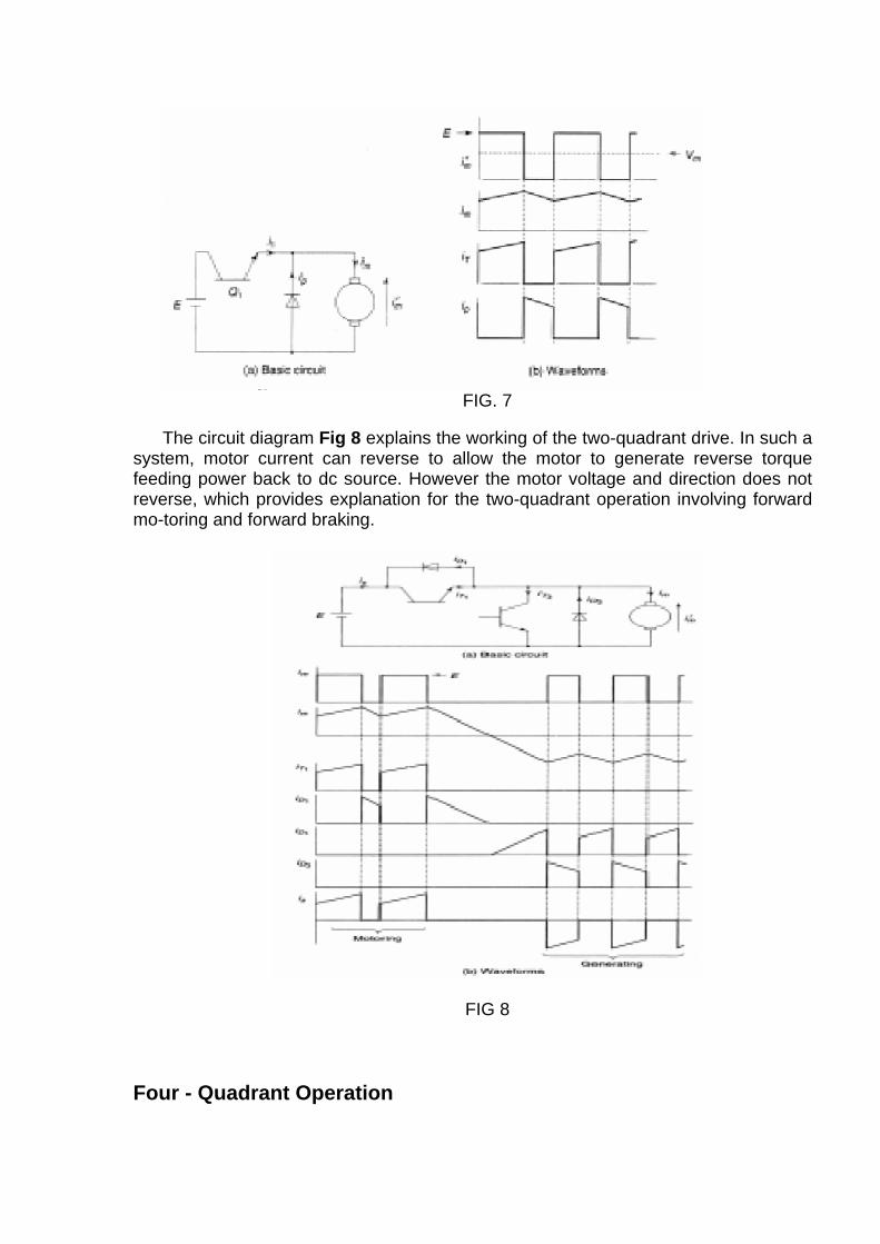
FIG. 7
The circuit diagram Fig 8 explains the working of the two-quadrant drive. In such a
system, motor current can reverse to allow the motor to generate reverse torque feeding power back to dc source. However the motor voltage and direction does not reverse, which provides explanation for the two-quadrant operation involving forward mo-toring and forward braking.
FIG 8
Four - Quadrant Operation
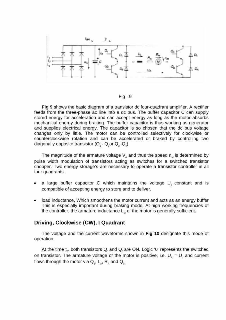
Fig - 9 Fig 9 shows the basic diagram of a transistor dc four-quadrant amplifier. A rectifier
feeds from the three-phase ac line into a dc bus. The buffer capacitor C can supply stored energy for acceleration and can accept energy as long as the motor absorbs mechanical energy during braking. The buffer capacitor is thus working as generator and supplies electrical energy. The capacitor is so chosen that the dc bus voltage changes only by little. The motor can be controlled selectively for clockwise or counterclockwise rotation and can be accelerated or braked by controlling two diagonally opposite transistor (Q1 - Q3or Q2 -Q4).
The magnitude of the armature voltage VA and thus the speed nM is determined by
pulse width modulation of transistors acting as switches for a switched transistor chopper. Two energy storage’s are necessary to operate a transistor controller in all tour quadrants. • a large buffer capacitor C which maintains the voltage Uc constant and is
compatible of accepting energy to store and to deliver. • load inductance, Which smoothens the motor current and acts as an energy buffer
This is especially important during braking mode. At high working frequencies of the controller, the armature inductance LM of the motor is generally sufficient.
Driving, Clockwise (CW), I Quadrant The voltage and the current waveforms shown in Fig 10 designate this mode of
operation. At the time t0, both transistors Q1 and Q3 are ON. Logic ‘0’ represents the switched
on transistor. The armature voltage of the motor is positive, i.e. UA = Uc and current flows through the motor via Q1, LA, RA and Q3.

At time t1 switch Q1 is opened. The motor current commutes from Q1 to diode D2
and is not flowing though the dc bus any more, but circulates in the lower half of the bridge from Q3 through D2. LA, RA motor and back to Q3 (free wheeling). At this point the motor voltage UA and the dc bus current i2 lump to zero.
At time t2 the situation is the same as it was at time t1. At time t3 switch Q3 is open.
The motor current now commutes though diode D4 and circulates in the upper half of the bridge circuit via Q1, LA, RA motor D4 and Q,. The motor voltage and do bus current
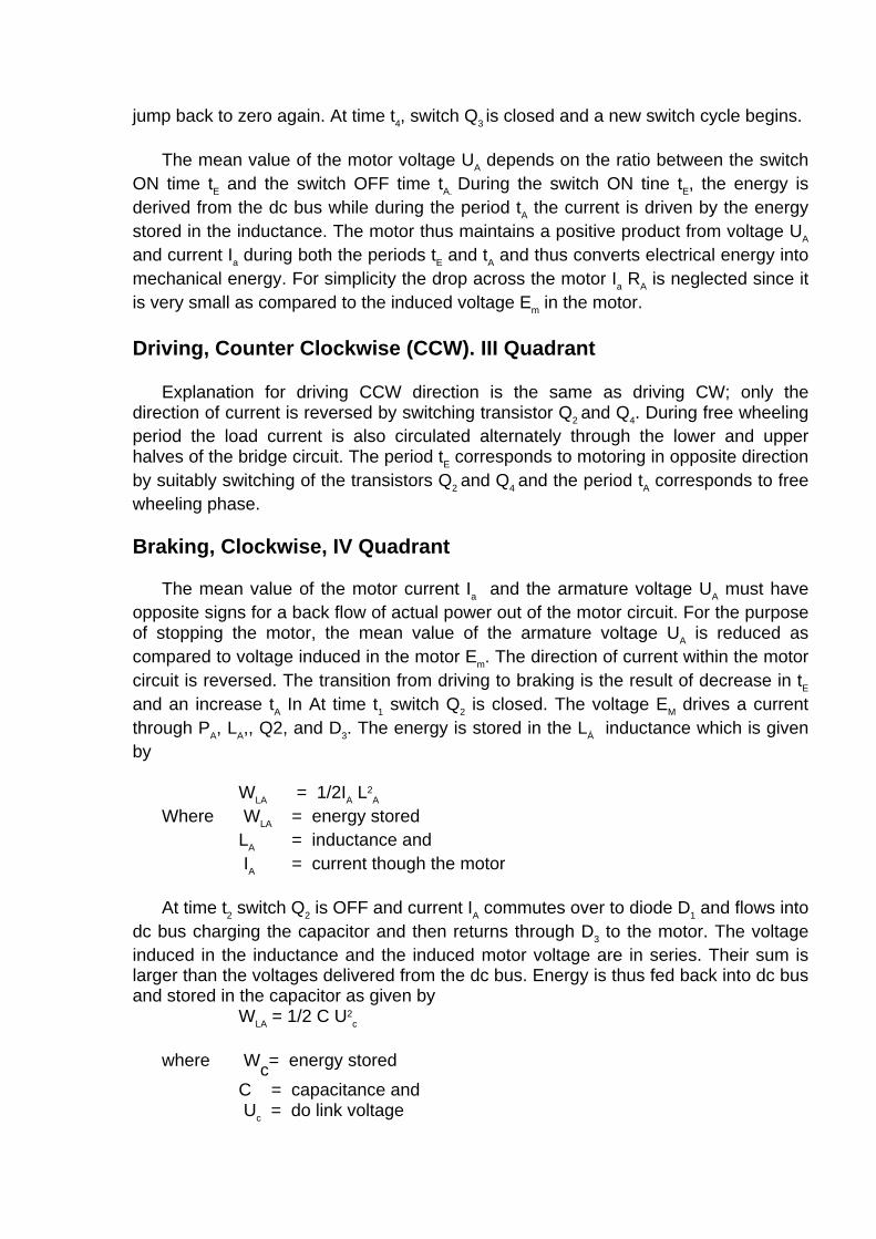
jump back to zero again. At time t4, switch Q3 is closed and a new switch cycle begins. The mean value of the motor voltage UA depends on the ratio between the switch
ON time tE and the switch OFF time tA. During the switch ON tine tE, the energy is derived from the dc bus while during the period tA the current is driven by the energy stored in the inductance. The motor thus maintains a positive product from voltage UA and current Ia during both the periods tE and tA and thus converts electrical energy into mechanical energy. For simplicity the drop across the motor Ia RA is neglected since it is very small as compared to the induced voltage Em in the motor.
Driving, Counter Clockwise (CCW). III Quadrant
Explanation for driving CCW direction is the same as driving CW; only the
direction of current is reversed by switching transistor Q2 and Q4. During free wheeling period the load current is also circulated alternately through the lower and upper halves of the bridge circuit. The period tE corresponds to motoring in opposite direction by suitably switching of the transistors Q2 and Q4 and the period tA corresponds to free wheeling phase.
Braking, Clockwise, IV Quadrant
The mean value of the motor current Ia and the armature voltage UA must have
opposite signs for a back flow of actual power out of the motor circuit. For the purpose of stopping the motor, the mean value of the armature voltage UA is reduced as compared to voltage induced in the motor Em. The direction of current within the motor circuit is reversed. The transition from driving to braking is the result of decrease in tE and an increase tA In At time t1 switch Q2 is closed. The voltage EM drives a current through PA, LA,, Q2, and D3. The energy is stored in the LÀ inductance which is given by
WLA = 1/2IA L2
A
Where WLA = energy stored LA = inductance and IA = current though the motor At time t2 switch Q2 is OFF and current IA commutes over to diode D1 and flows into
dc bus charging the capacitor and then returns through D3 to the motor. The voltage induced in the inductance and the induced motor voltage are in series. Their sum is larger than the voltages delivered from the dc bus. Energy is thus fed back into dc bus and stored in the capacitor as given by
WLA = 1/2 C U2c
where Wc= energy stored
C = capacitance and Uc = do link voltage
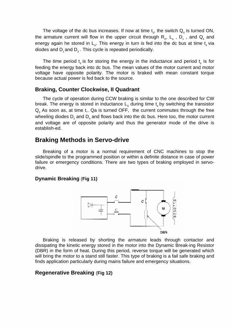
The voltage of the dc bus increases. If now at time t3, the switch Q4 is turned ON, the armature current will flow in the upper circuit through RA, La , D1 , and Q4 and energy again he stored in LA. This energy in turn is fed into the dc bus at time t4 via diodes and D1 and D3 . This cycle is repeated periodically.
The time period t4 is for storing the energy in the inductance and period te is for
feeding the energy back into dc bus. The mean values of the motor current and motor voltage have opposite polarity. The motor is braked with mean constant torque because actual power is fed back to the source.
Braking, Counter Clockwise, II Quadrant
The cycle of operation during CCW braking is similar to the one described for CW break. The energy is stored in inductance LÀ during time t4 by switching the transistor Q3 As soon as, at time t,. Qa is turned OFF, the current commutes through the free wheeling diodes D2 and D4 and flows back into the dc bus. Here too, the motor current and voltage are of opposite polarity and thus the generator mode of the drive is establish-ed.
Braking Methods in Servo-drive
Breaking of a motor is a normal requirement of CNC machines to stop the
slide/spindle to the programmed position or within a definite distance in case of power failure or emergency conditions. There are two types of braking employed in servo-drive.
Dynamic Breaking (Fig 11)
Braking is released by shorting the armature leads through contactor and
dissipating the kinetic energy stored in the motor into the Dynamic Break-ing Resistor (DBR) in the form of heat. During this period, reverse torque will be generated which will bring the motor to a stand still faster. This type of braking is a fail safe braking and finds application particularly during mains failure and emergency situations.
Regenerative Breaking (Fig 12)
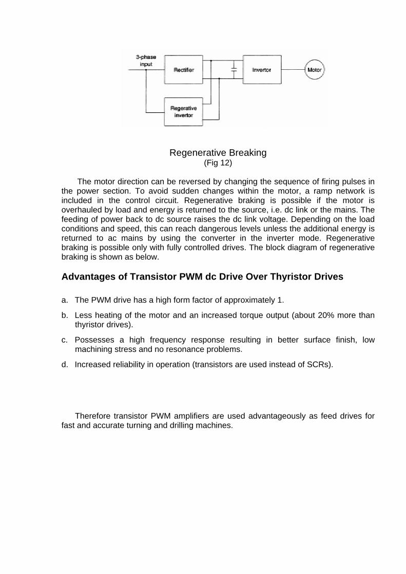
Regenerative Breaking
(Fig 12)
The motor direction can be reversed by changing the sequence of firing pulses in the power section. To avoid sudden changes within the motor, a ramp network is included in the control circuit. Regenerative braking is possible if the motor is overhauled by load and energy is returned to the source, i.e. dc link or the mains. The feeding of power back to dc source raises the dc link voltage. Depending on the load conditions and speed, this can reach dangerous levels unless the additional energy is returned to ac mains by using the converter in the inverter mode. Regenerative braking is possible only with fully controlled drives. The block diagram of regenerative braking is shown as below.
Advantages of Transistor PWM dc Drive Over Thyristor Drives
a. The PWM drive has a high form factor of approximately 1.
b. Less heating of the motor and an increased torque output (about 20% more than thyristor drives).
c. Possesses a high frequency response resulting in better surface finish, low machining stress and no resonance problems.
d. Increased reliability in operation (transistors are used instead of SCRs).
Therefore transistor PWM amplifiers are used advantageously as feed drives for fast and accurate turning and drilling machines.
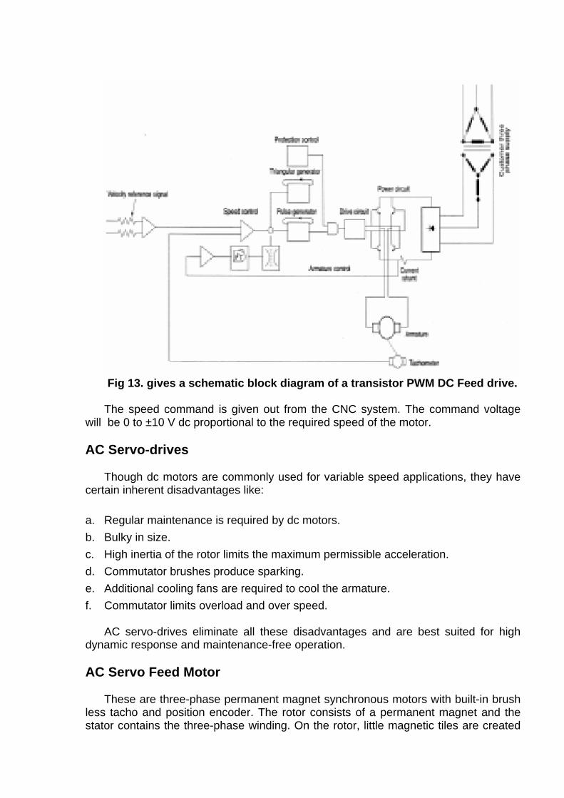
Fig 13. gives a schematic block diagram of a transistor PWM DC Feed drive. The speed command is given out from the CNC system. The command voltage
will be 0 to ±10 V dc proportional to the required speed of the motor.
AC Servo-drives Though dc motors are commonly used for variable speed applications, they have
certain inherent disadvantages like:
a. Regular maintenance is required by dc motors. b. Bulky in size. c. High inertia of the rotor limits the maximum permissible acceleration. d. Commutator brushes produce sparking. e. Additional cooling fans are required to cool the armature. f. Commutator limits overload and over speed.
AC servo-drives eliminate all these disadvantages and are best suited for high
dynamic response and maintenance-free operation.
AC Servo Feed Motor These are three-phase permanent magnet synchronous motors with built-in brush
less tacho and position encoder. The rotor consists of a permanent magnet and the stator contains the three-phase winding. On the rotor, little magnetic tiles are created
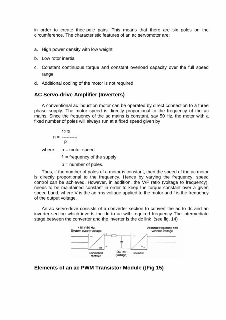
in order to create thee-pole pairs. This means that there are six poles on the circumference. The characteristic features of an ac servomotor are;
a. High power density with low weight
b. Low rotor inertia
c. Constant continuous torque and constant overload capacity over the full speed range
d. Additional cooling of the motor is not required AC Servo-drive Amplifier (Inverters)
A conventional ac induction motor can be operated by direct connection to a three
phase supply. The motor speed is directly proportional to the frequency of the ac mains. Since the frequency of the ac mains is constant, say 50 Hz, the motor with a fixed number of poles will always run at a fixed speed given by
120f n = ---------- P where n = motor speed f = frequency of the supply p = number of poles. Thus, if the number of poles of a motor is constant, then the speed of the ac motor
is directly proportional to the frequency. Hence by varying the frequency, speed control can be achieved. However, in addition, the V/F ratio (voltage to frequency), needs to be maintained constant in order to keep the torque constant over a given speed band, where V is the ac rms voltage applied to the motor and f is the frequency of the output voltage.
An ac servo-drive consists of a converter section to convert the ac to dc and an
inverter section which inverts the dc to ac with required frequency The intermediate stage between the converter and the inverter is the dc link (see fig. 14)
Elements of an ac PWM Transistor Module ((Fig 15)
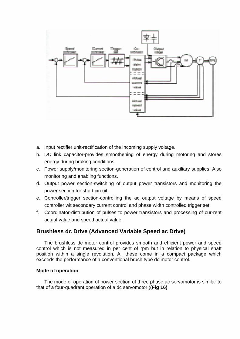
a. Input rectifier unit-rectification of the incoming supply voltage. b. DC link capacitor-provides smoothening of energy during motoring and stores
energy during braking conditions. c. Power supply/monitoring section-generation of control and auxiliary supplies. Also
monitoring and enabling functions. d. Output power section-switching of output power transistors and monitoring the
power section for short circuit, e. Controller/trigger section-controlling the ac output voltage by means of speed
controller wit secondary current control and phase width controlled trigger set. f. Coordinator-distribution of pulses to power transistors and processing of cur-rent
actual value and speed actual value.
Brushless dc Drive (Advanced Variable Speed ac Drive) The brushless dc motor control provides smooth and efficient power and speed
control which is not measured in per cent of rpm but in relation to physical shaft position within a single revolution. All these come in a compact package which exceeds the performance of a conventional brush type dc motor control.
Mode of operation
The mode of operation of power section of three phase ac servomotor is similar to
that of a four-quadrant operation of a dc servomotor ((Fig 16)

The three-phase ac power is converted to dc by the bridge converter which
charges a bank of storage capacitors called the dc bus. The size of the bus varies depending upon the connected load.
The rectification is accomplished by six diodes or thyristors which may be in a
single package or in several modules. The diodes are protected by input fuses. The selection of incoming fuses is based on speed and interrupting capacity, An input choke in the dc side of the rectifier bridge protects against the line transients and limits the rate of change of current,
The input section of this controller is self regulating. The maximum voltage
possible across the capacitors is 2 times the incoming line voltage. Initially, before the motor is switched ON, the capacitors are charged to this peak value which forms the bus voltage. When the motor is started, it uses power from the bus to perform the work required. The effect of this is to partially discharge the capacitors lowering the bus voltage. With three-phase input power, there are six periods in each cycle of ac when the line-to-line voltage is greater than the capacitor voltage. The capacitors will only draw current from the power lines when the bus voltage is lower than the instantaneous line to line voltage and then it will draw enough power to replenish the energy consumed by the motor since the last time the line-to-line voltage was greater than the capacitor voltage.
The torque in a motor is a function of current, Power is a function of speed and torque. Even though the current required by the motor to develop the torque may be large, the actual power used is small at low speeds. The energy drawn from the capacitor bank is the actual power used by the motor and the energy drawn from the supply mains is the actual power supplied to the motor.
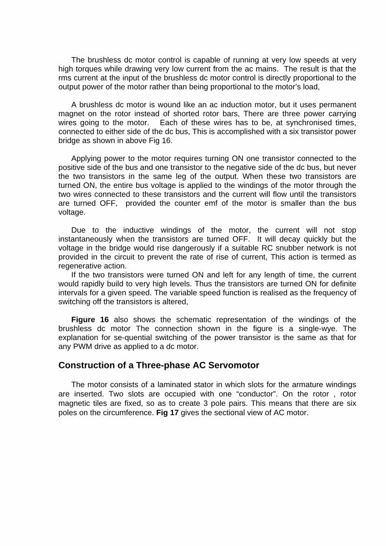
The brushless dc motor control is capable of running at very low speeds at very
high torques while drawing very low current from the ac mains. The result is that the rms current at the input of the brushless dc motor control is directly proportional to the output power of the motor rather than being proportional to the motor’s load,
A brushless dc motor is wound like an ac induction motor, but it uses permanent
magnet on the rotor instead of shorted rotor bars, There are three power carrying wires going to the motor. Each of these wires has to be, at synchronised times, connected to either side of the dc bus, This is accomplished with a six transistor power bridge as shown in above Fig 16.
Applying power to the motor requires turning ON one transistor connected to the
positive side of the bus and one transistor to the negative side of the dc bus, but never the two transistors in the same leg of the output. When these two transistors are turned ON, the entire bus voltage is applied to the windings of the motor through the two wires connected to these transistors and the current will flow until the transistors are turned OFF, provided the counter emf of the motor is smaller than the bus voltage.
Due to the inductive windings of the motor, the current will not stop
instantaneously when the transistors are turned OFF. It will decay quickly but the voltage in the bridge would rise dangerously if a suitable RC snubber network is not provided in the circuit to prevent the rate of rise of current, This action is termed as regenerative action.
If the two transistors were turned ON and left for any length of time, the current would rapidly build to very high levels. Thus the transistors are turned ON for definite intervals for a given speed. The variable speed function is realised as the frequency of switching off the transistors is altered,
Figure 16 also shows the schematic representation of the windings of the
brushless dc motor The connection shown in the figure is a single-wye. The explanation for se-quential switching of the power transistor is the same as that for any PWM drive as applied to a dc motor.
Construction of a Three-phase AC Servomotor
The motor consists of a laminated stator in which slots for the armature windings
are inserted. Two slots are occupied with one “conductor”. On the rotor , rotor magnetic tiles are fixed, so as to create 3 pole pairs. This means that there are six poles on the circumference. Fig 17 gives the sectional view of AC motor.
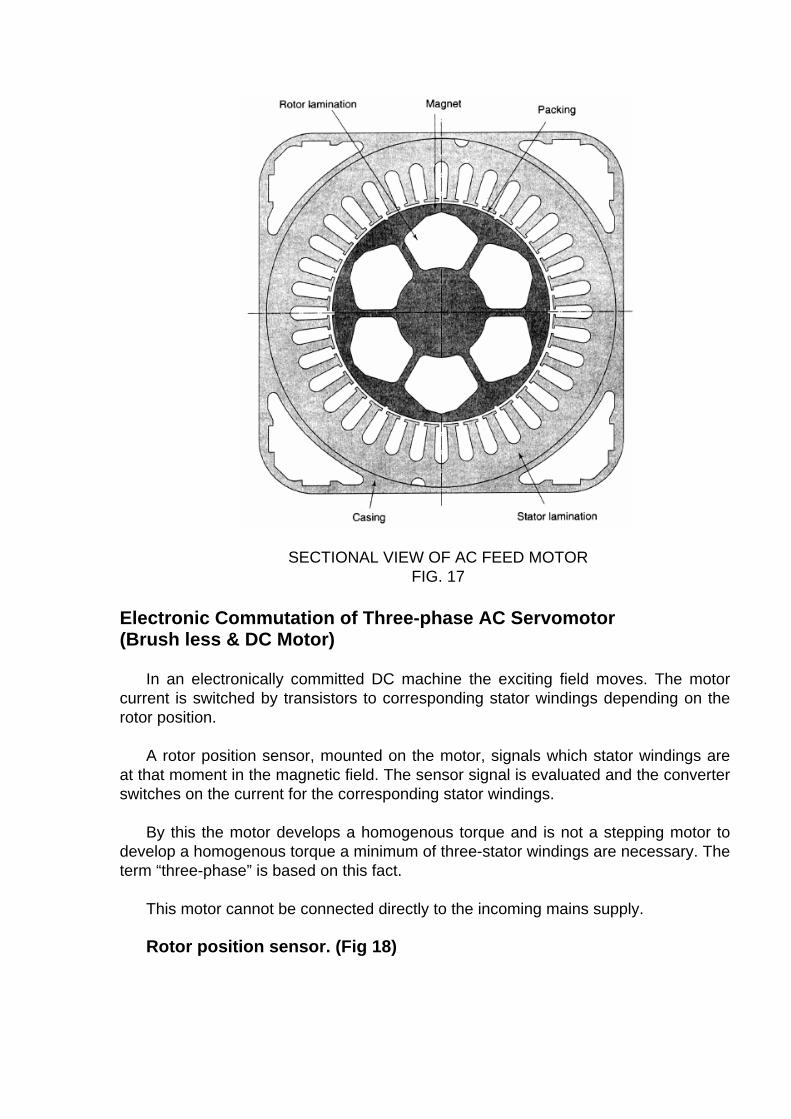
SECTIONAL VIEW OF AC FEED MOTOR FIG. 17
Electronic Commutation of Three-phase AC Servomotor (Brush less & DC Motor)
In an electronically committed DC machine the exciting field moves. The motor
current is switched by transistors to corresponding stator windings depending on the rotor position.
A rotor position sensor, mounted on the motor, signals which stator windings are
at that moment in the magnetic field. The sensor signal is evaluated and the converter switches on the current for the corresponding stator windings.
By this the motor develops a homogenous torque and is not a stepping motor to
develop a homogenous torque a minimum of three-stator windings are necessary. The term “three-phase” is based on this fact.
This motor cannot be connected directly to the incoming mains supply. Rotor position sensor. (Fig 18)
The rotor position is sampled via magnetic fork type barriers. A disc three soft iron
shutters at a distance of 60° is fixed with a cone. The magnetic fork type barriers are connected to the stator with clam screws. For adjustment the screws can be opened and the barrier support can be turned. The signals led to the converter via a plug.
HALL EFFECT
The Hall Effect switch is handled by a soft iron shutter which is placed in the air
gap between magnet and Hall sensor. The barrier short-circuits the magnetic flux before the Hall sensor.
The open collector output is current carrying (low), if the barrier is outside the air
gap and locks (high) as soon as the barrier penetrates the air gap. As long as the barrier is placed in the air gap, the output remains closed.
Based on the static operation mode, the signal performance is independent of
rotation speed. The output signal slopes are independent of the operation frequency. The circuit has an integrated over voltage protection against most voltage peaks using a Schmitt trigger type output section. The maximum output current or 40 A of the open collector causes the most electronic circuits triggered directly.
DRIVE PROTECTION
One of the important feature of any drive amplifier or a controller is to provide a
high degree of protection to the motor and the drive itself. Every drive amplifier consists of a monitoring module to perform protective functions such as:
a. Voltage monitoring b. Fuse failure monitoring c. Motor connection continuity check

d. Tacho feedback circuit fault monitoring e. Motor current limiting f. Power ( I2 t ) monitoring g. Voltage Limiting(regenerative voltage) h. Maximum speed monitoring i. Motor temperature monitoring j. Internal circuit function monitoring k. Wrong connection check
In case of the above faults, the drive will stop and the status is displayed by diodes
(LED). Also, the fault message is communicated to the CNC system to draw the operator’s attention.
In addition to the internal monitoring circuits, drive amplifiers are also protected
against overloads, short circuits, and non-voltage circuits externally in the control panel by the machine builder.
Feed motor should have IP 64 degree of protection with built-in thermistor to
monitor the motor temperature. Spindle motors usually confirm to IP 54 degree of protection with built-in thermistor protection.
ELECTRIC ELEMENTS The schematic diagram in the following figure shows a typical CNC system. Other
than drives there are several electrical and electro mechanical devices used as control elements. These elements form the input or output devices for the CNC system.
CR: CONTROL RELAY LS: LIMIT SWITCH OL: OVER LOAD PB: PUSH BUTTON PRS: PROXIMITY SWITCH PS: PRESSURE SWITCH SOL: SOLENOID
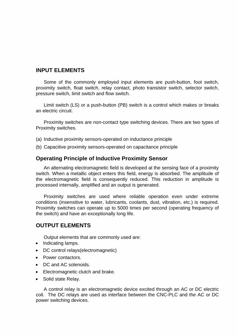
INPUT ELEMENTS
Some of the commonly employed input elements are push-button, foot switch,
proximity switch, float switch, relay contact, photo transistor switch, selector switch, pressure switch, limit switch and flow switch.
Limit switch (LS) or a push-button (PB) switch is a control which makes or breaks
an electric circuit. Proximity switches are non-contact type switching devices. There are two types of
Proximity switches.
(a) Inductive proximity sensors-operated on inductance principle (b) Capacitive proximity sensors-operated on capacitance principle
Operating Principle of Inductive Proximity Sensor
An alternating electromagnetic field is developed at the sensing face of a proximity switch. When a metallic object enters this field, energy is absorbed. The amplitude of the electromagnetic field is consequently reduced. This reduction in amplitude is processed internally, amplified and an output is generated.
Proximity switches are used where reliable operation even under extreme
conditions (insensitive to water, lubricants, coolants, dust, vibration, etc.) is required. Proximity switches can operate up to 5000 times per second (operating frequency of the switch) and have an exceptionally long life.
OUTPUT ELEMENTS
Output elements that are commonly used are:
• Indicating lamps. • DC control relays(electromagnetic) • Power contactors. • DC and AC solenoids. • Electromagnetic clutch and brake. • Solid state Relay.
A control relay is an electromagnetic device excited through an AC or DC electric
coil. The DC relays are used as interface between the CNC-PLC and the AC or DC power switching devices.
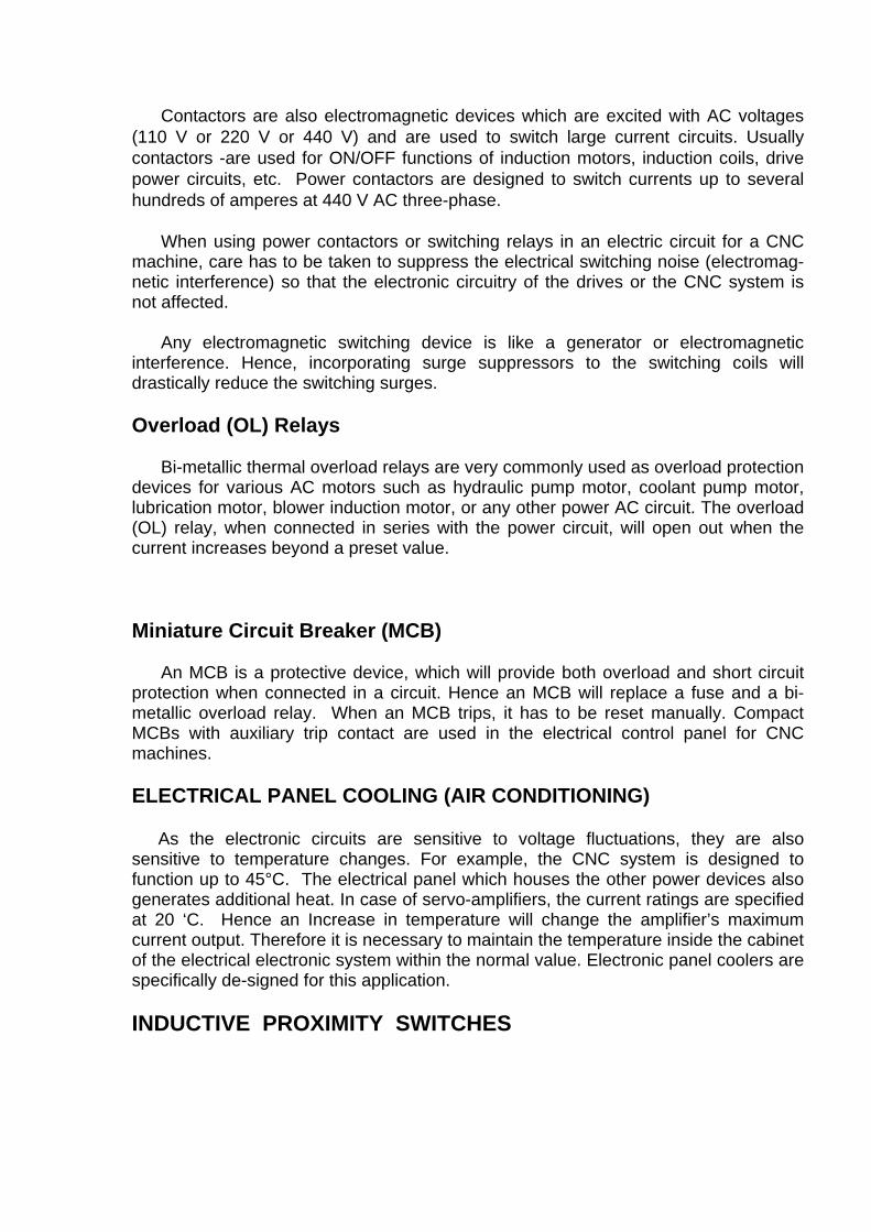
Contactors are also electromagnetic devices which are excited with AC voltages (110 V or 220 V or 440 V) and are used to switch large current circuits. Usually contactors -are used for ON/OFF functions of induction motors, induction coils, drive power circuits, etc. Power contactors are designed to switch currents up to several hundreds of amperes at 440 V AC three-phase.
When using power contactors or switching relays in an electric circuit for a CNC
machine, care has to be taken to suppress the electrical switching noise (electromag-netic interference) so that the electronic circuitry of the drives or the CNC system is not affected.
Any electromagnetic switching device is like a generator or electromagnetic
interference. Hence, incorporating surge suppressors to the switching coils will drastically reduce the switching surges.
Overload (OL) Relays
Bi-metallic thermal overload relays are very commonly used as overload protection
devices for various AC motors such as hydraulic pump motor, coolant pump motor, lubrication motor, blower induction motor, or any other power AC circuit. The overload (OL) relay, when connected in series with the power circuit, will open out when the current increases beyond a preset value.
Miniature Circuit Breaker (MCB) An MCB is a protective device, which will provide both overload and short circuit
protection when connected in a circuit. Hence an MCB will replace a fuse and a bi-metallic overload relay. When an MCB trips, it has to be reset manually. Compact MCBs with auxiliary trip contact are used in the electrical control panel for CNC machines.
ELECTRICAL PANEL COOLING (AIR CONDITIONING) As the electronic circuits are sensitive to voltage fluctuations, they are also sensitive to temperature changes. For example, the CNC system is designed to function up to 45°C. The electrical panel which houses the other power devices also generates additional heat. In case of servo-amplifiers, the current ratings are specified at 20 ‘C. Hence an Increase in temperature will change the amplifier’s maximum current output. Therefore it is necessary to maintain the temperature inside the cabinet of the electrical electronic system within the normal value. Electronic panel coolers are specifically de-signed for this application. INDUCTIVE PROXIMITY SWITCHES
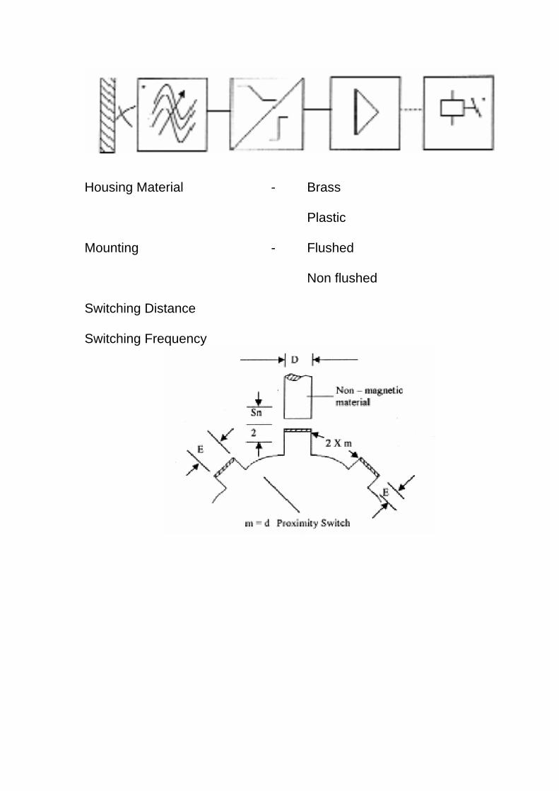
Housing Material - Brass Plastic Mounting - Flushed Non flushed Switching Distance Switching Frequency
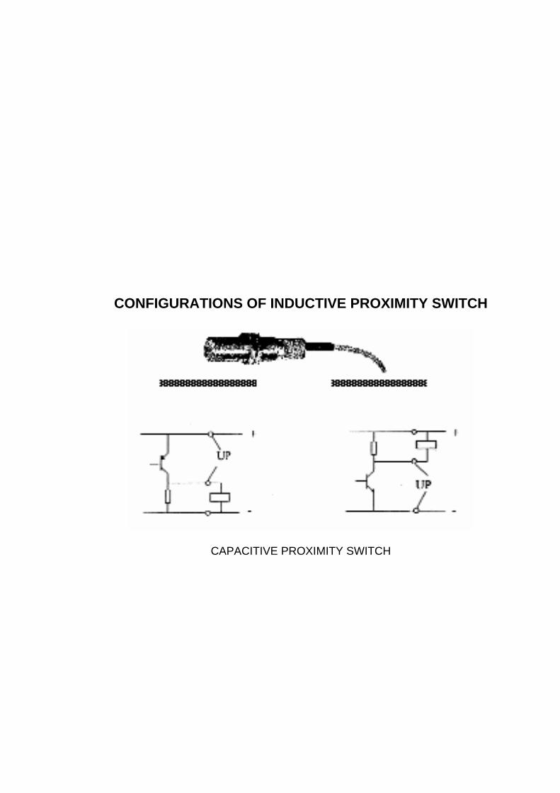
CONFIGURATIONS OF INDUCTIVE PROXIMITY SWITCH
CAPACITIVE PROXIMITY SWITCH
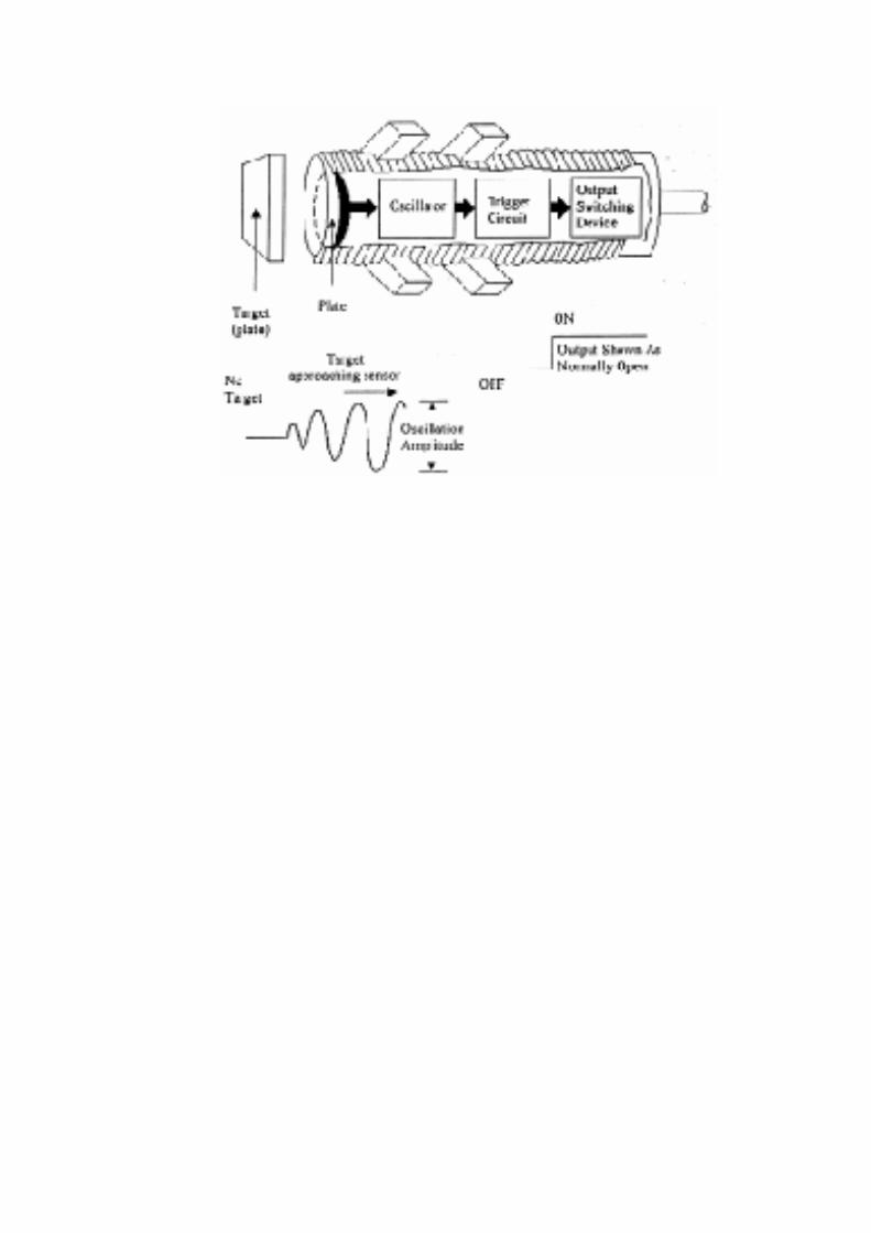
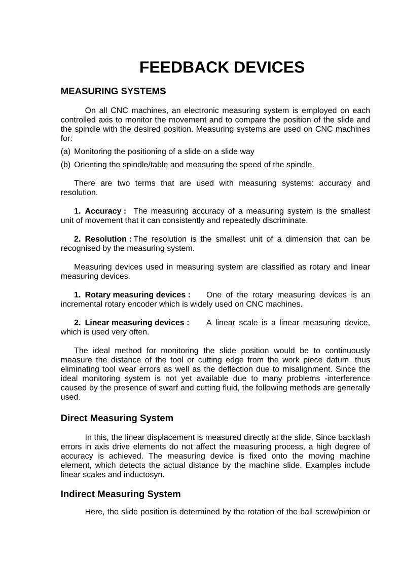
FEEDBACK DEVICES
MEASURING SYSTEMS On all CNC machines, an electronic measuring system is employed on each
controlled axis to monitor the movement and to compare the position of the slide and the spindle with the desired position. Measuring systems are used on CNC machines for: (a) Monitoring the positioning of a slide on a slide way (b) Orienting the spindle/table and measuring the speed of the spindle.
There are two terms that are used with measuring systems: accuracy and
resolution. 1. Accuracy : The measuring accuracy of a measuring system is the smallest
unit of movement that it can consistently and repeatedly discriminate. 2. Resolution : The resolution is the smallest unit of a dimension that can be
recognised by the measuring system. Measuring devices used in measuring system are classified as rotary and linear
measuring devices. 1. Rotary measuring devices : One of the rotary measuring devices is an
incremental rotary encoder which is widely used on CNC machines. 2. Linear measuring devices : A linear scale is a linear measuring device,
which is used very often. The ideal method for monitoring the slide position would be to continuously
measure the distance of the tool or cutting edge from the work piece datum, thus eliminating tool wear errors as well as the deflection due to misalignment. Since the ideal monitoring system is not yet available due to many problems -interference caused by the presence of swarf and cutting fluid, the following methods are generally used. Direct Measuring System In this, the linear displacement is measured directly at the slide, Since backlash errors in axis drive elements do not affect the measuring process, a high degree of accuracy is achieved. The measuring device is fixed onto the moving machine element, which detects the actual distance by the machine slide. Examples include linear scales and inductosyn. Indirect Measuring System Here, the slide position is determined by the rotation of the ball screw/pinion or
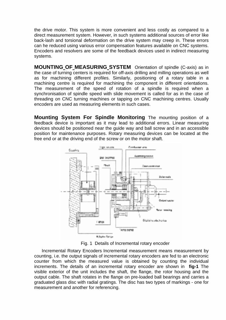
the drive motor. This system is more convenient and less costly as compared to a direct measurement system. However, in such systems additional sources of error like back-lash and torsional deformation on the drive system may creep in. These errors can he reduced using various error compensation features available on CNC systems. Encoders and resolvers are some of the feedback devices used in indirect measuring systems.
MOUNTING OF MEASURING SYSTEM Orientation of spindle (C-axis) as in the case of turning centers is required for off-axis drilling and milling operations as well as for machining different profiles. Similarly, positioning of a rotary table in a machining centre is required for machining the component in different orientations. The measurement of the speed of rotation of a spindle is required when a synchronisation of spindle speed with slide movement is called for as in the case of threading on CNC turning machines or tapping on CNC machining centres. Usually encoders are used as measuring elements in such cases.
Mounting System For Spindle Monitoring The mounting position of a feedback device is important as it may lead to additional errors. Linear measuring devices should be positioned near the guide way and ball screw and in an accessible position for maintenance purposes. Rotary measuring devices can be located at the free end or at the driving end of the screw or on the motor shaft.
Fig. 1 Details of Incremental rotary encoder
Incremental Rotary Encoders Incremental measurement means measurement by counting, i.e. the output signals of incremental rotary encoders are fed to an electronic counter from which the measured value is obtained by counting the individual increments. The details of an incremental rotary encoder are shown in fig-1 The visible exterior of the unit includes the shaft, the flange, the rotor housing and the output cable. The shaft rotates in the flange on pre-loaded ball bearings and carries a graduated glass disc with radial gratings. The disc has two types of markings - one for measurement and another for referencing.
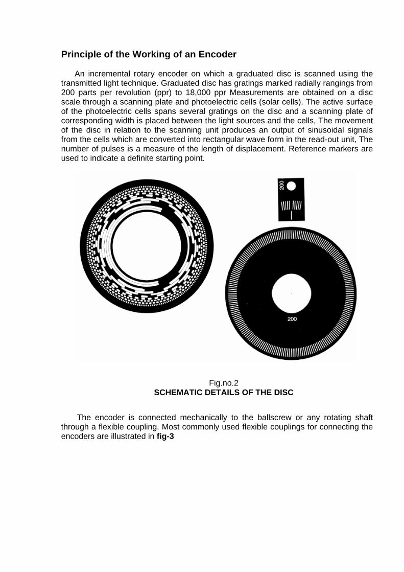
Principle of the Working of an Encoder An incremental rotary encoder on which a graduated disc is scanned using the
transmitted light technique. Graduated disc has gratings marked radially rangings from 200 parts per revolution (ppr) to 18,000 ppr Measurements are obtained on a disc scale through a scanning plate and photoelectric cells (solar cells). The active surface of the photoelectric cells spans several gratings on the disc and a scanning plate of corresponding width is placed between the light sources and the cells, The movement of the disc in relation to the scanning unit produces an output of sinusoidal signals from the cells which are converted into rectangular wave form in the read-out unit, The number of pulses is a measure of the length of displacement. Reference markers are used to indicate a definite starting point.
Fig.no.2
SCHEMATIC DETAILS OF THE DISC The encoder is connected mechanically to the ballscrew or any rotating shaft
through a flexible coupling. Most commonly used flexible couplings for connecting the encoders are illustrated in fig-3
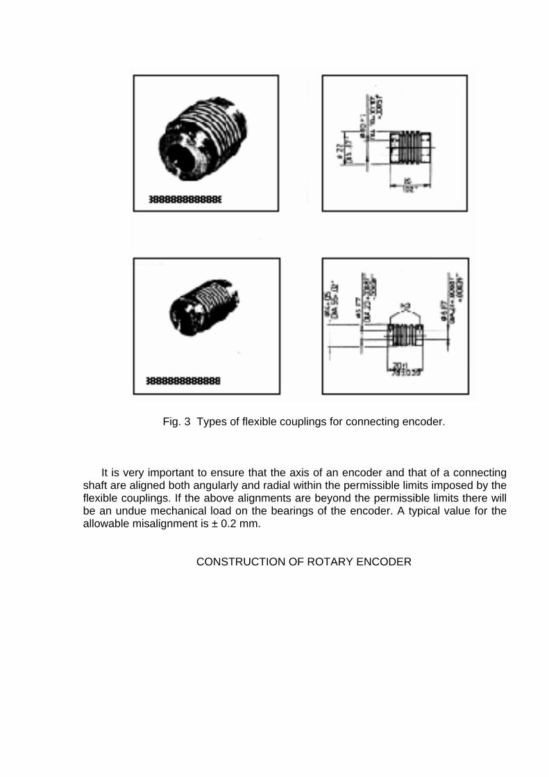
Fig. 3 Types of flexible couplings for connecting encoder. It is very important to ensure that the axis of an encoder and that of a connecting
shaft are aligned both angularly and radial within the permissible limits imposed by the flexible couplings. If the above alignments are beyond the permissible limits there will be an undue mechanical load on the bearings of the encoder. A typical value for the allowable misalignment is ± 0.2 mm.
CONSTRUCTION OF ROTARY ENCODER
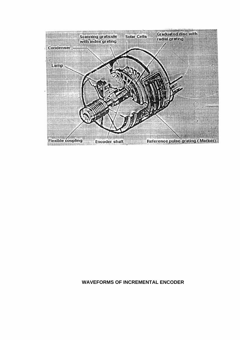
WAVEFORMS OF INCREMENTAL ENCODER
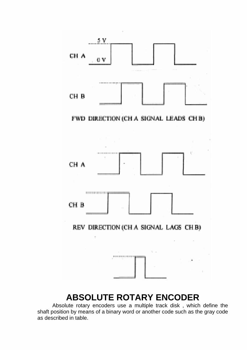
ABSOLUTE ROTARY ENCODER Absolute rotary encoders use a multiple track disk , which define the shaft position by means of a binary word or another code such as the gray code as described in table.

FIG. BINARY CODE DISK OF ABSOLUTE ENCODER
The reading system employs a lamp and photocells to detect the light, which passes through the transparent portions of the disk. A photocell is provided for each track on the disk. The output from allcells gives the actual shaft position in coded form.
Absolute encoders are most suitable for robots and rotary tables
BINARY CODE DECIMAL NUMBER 8 4 2 1
GRAY CODE
1 0 0 0 1 0 0 0 1 2 0 0 1 0 0 0 1 1 3 0 0 1 1 0 0 1 0 4 0 1 0 0 0 1 1 0 5 0 1 0 1 0 1 1 1 6 0 1 1 0 0 1 0 1 7 0 1 1 1 0 1 0 0 8 1 0 0 0 1 1 0 0
a b c d A B C D A=a; B=a+b; C=b+c; D=c=d;
TABLE : BINARY / GRAY CODES
RESOLVER
This is analog type of rotary feedback device since the rotary motion of
the resolver is converted into linear distance. It is also called as the Inidrect
type of feedback device.
The resolver has got 2 stator windings and 1 rotor winding. The two-
stator windings are aligned in such a way to give 900-phase shift. The starter
and the rotar windings are mechanically aligned to provide transformer action.
i.e. when the two windings are excited with sinusoidal signals of 900 phase shift,
voltage is induced in the rotor, which is also a sinusoidal signal. As the resolver
shaft rotates, the output signal varies in phase with respect to reference signal
(one of stator inputs) The magnitude of phase shift is directly proportional to the
number of mechanical degrees by which resolver shaft is rotated.
Since the cnc system can understand only the digital information, i.e 0v
and 5v, it is required to convert the output of resolver into digital signals. As the
resolver shaft rotates, the output signal from the rotor varies in phase with
respect to stator windings from 00 to 3600. Hence phase shift of the resolver
output has to be converted into fixed number of pulses in order to determine the
actual position of the machine tool.
RESOLVER
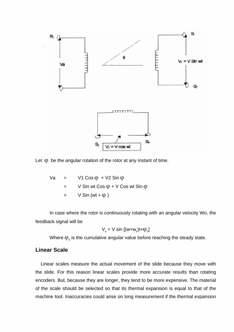
Let ϕ be the angular rotation of the rotor at any instant of time.
Va = V1 Cos ϕ + V2 Sin ϕ
= V Sin wt Cos ϕ + V Cos wt Sin ϕ
= V Sin (wt + ϕ )
In case where the rotor is continuously rotating with an angular velocity Wo, the
feedback signal will be Va = V sin [(w+w0)t+ϕ0]
Where ϕ0 is the cumulative angular value before reaching the steady state.
Linear Scale
Linear scales measure the actual movement of the slide because they move with
the slide. For this reason linear scales provide more accurate results than rotating
encoders. But, because they are longer, they tend to be more expensive. The material
of the scale should be selected so that its thermal expansion is equal to that of the
machine tool. Inaccuracies could arise on long measurement if the thermal expansion
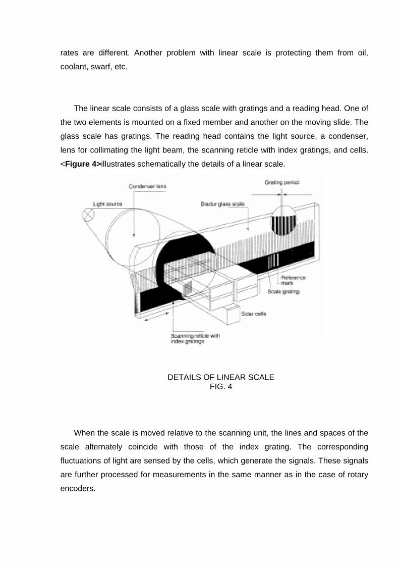
rates are different. Another problem with linear scale is protecting them from oil,
coolant, swarf, etc.
The linear scale consists of a glass scale with gratings and a reading head. One of
the two elements is mounted on a fixed member and another on the moving slide. The
glass scale has gratings. The reading head contains the light source, a condenser,
lens for collimating the light beam, the scanning reticle with index gratings, and cells.
<Figure 4>illustrates schematically the details of a linear scale.
DETAILS OF LINEAR SCALE FIG. 4
When the scale is moved relative to the scanning unit, the lines and spaces of the
scale alternately coincide with those of the index grating. The corresponding
fluctuations of light are sensed by the cells, which generate the signals. These signals
are further processed for measurements in the same manner as in the case of rotary
encoders.
LINEAR INDUCTOSYN
The Inductosyn can be considered as a form of iron less synchro resolver,
which is unwound as a flat surface. The element equivalent to resolver rotor is known
as scale and that of the resolver stator is known as a slider. The scale is fitted to
machine bed and the slider (fitted to the moving member of the machine) moves over
the scale. In the case of inductosyn multiple poles are used and because of averaging
effect of multipolar winding any slight local error in the winding is compensated by the
other.
Liner inductosyn are available in two forms.
1. Metal inductosyn.
2. Tape inductosyn.
Linear inductosyn is made with a conductor spacing of 2 mm. (also called pitch.) The slider has 64 or 96 poles & is approximately 4” in length. The scales are furnished in 10” length. Scale segments are customarily arranged end to end to provide measurement over large distances. Tape inductosyn is available on continuous steel tape to any length. The steel tape is having supported at both the ends and a tension adjustment facility keeps the tape straight. The gap between the slides and the scale should be maintained at about 200 µ to ensure the optimum signal strength. The gap adjustment is tedious process in case of a tape inductosyns. Rotary inductosyns are used for measuring angular positions. The rotary inductosyn transducer consists of a rotor and a stator. Any one can be attached to the rotating shaft whose motion is to be measured, while the other is fixed to the bearing or the mount. Rotary inductosyn possess very high accuracy of measurement of the order of 1 arc second. INDUCTOSYN EQUATION Linear inductosyn is an analog type of direct feed back device. The fig shows inductosyn consisting of single hairpin winding of 2-mm pitch. Adjacent and separated
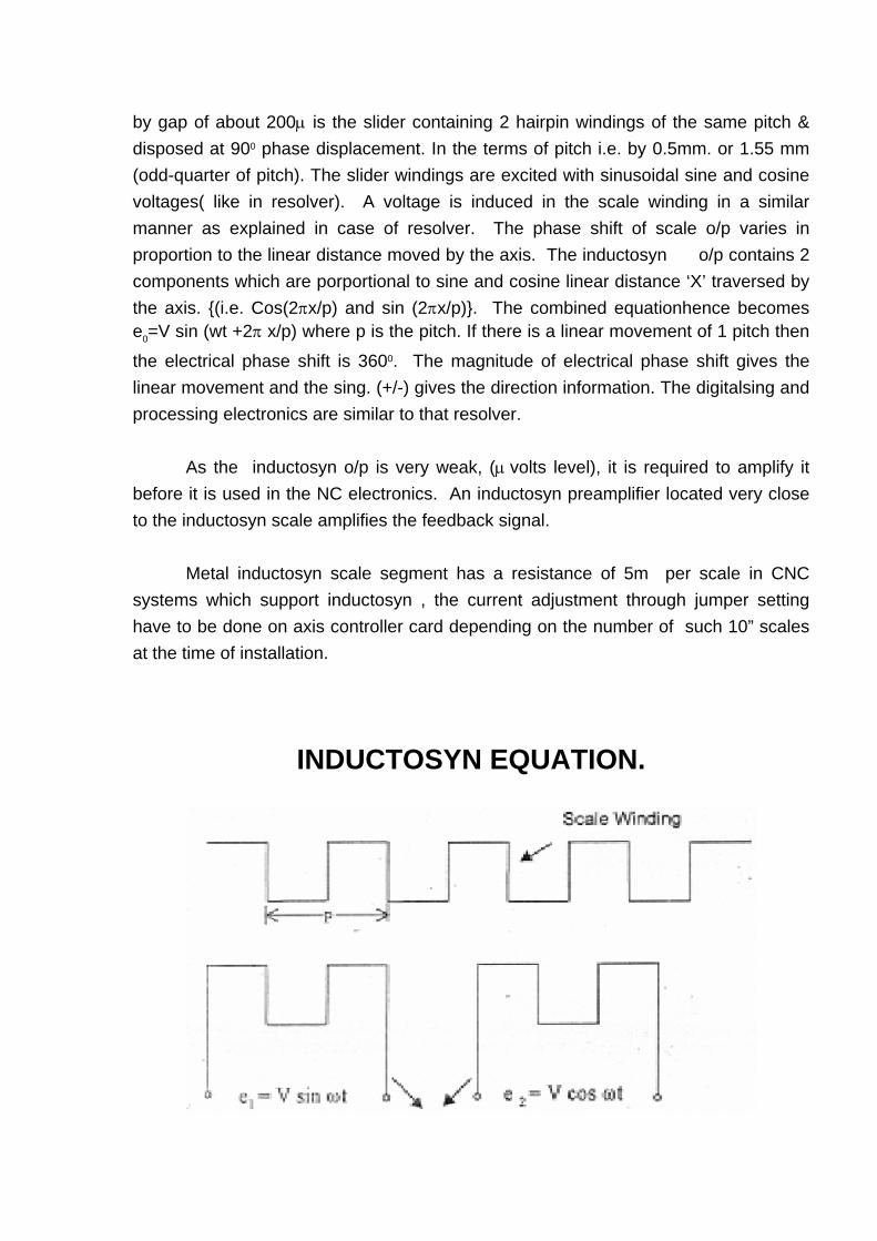
by gap of about 200µ is the slider containing 2 hairpin windings of the same pitch & disposed at 900 phase displacement. In the terms of pitch i.e. by 0.5mm. or 1.55 mm (odd-quarter of pitch). The slider windings are excited with sinusoidal sine and cosine voltages( like in resolver). A voltage is induced in the scale winding in a similar manner as explained in case of resolver. The phase shift of scale o/p varies in proportion to the linear distance moved by the axis. The inductosyn o/p contains 2 components which are porportional to sine and cosine linear distance ‘X’ traversed by the axis. {(i.e. Cos(2πx/p) and sin (2πx/p)}. The combined equationhence becomes e0=V sin (wt +2π x/p) where p is the pitch. If there is a linear movement of 1 pitch then
the electrical phase shift is 3600. The magnitude of electrical phase shift gives the linear movement and the sing. (+/-) gives the direction information. The digitalsing and processing electronics are similar to that resolver. As the inductosyn o/p is very weak, (µ volts level), it is required to amplify it before it is used in the NC electronics. An inductosyn preamplifier located very close to the inductosyn scale amplifies the feedback signal. Metal inductosyn scale segment has a resistance of 5m per scale in CNC systems which support inductosyn , the current adjustment through jumper setting have to be done on axis controller card depending on the number of such 10” scales at the time of installation.
INDUCTOSYN EQUATION.
SLIDER WINDINGS
LET P = PITCH OF THE SCALE X = LINEAR DISTANCE MOVED BY THE SCALE. IF THE SCALE MOVES BY ONE PITCH IT EXPERIENCES 3600 PHASE SHIFT AT THE OUTPUT. INDUCTOSYN EQUATION : WHEN THE SCALE MOVES BY DISTANCE ‘X’ VOLTAGE IN THE SCALE DUE TO e1 = e1 Cos (2κπ x /p) VOLTAGE INDUCED IN THE SCALE DUE TO e2 = es SIN ( 2π x /p) REULTANT VOLTAGE IN THE SCALE : e0 =V Sin Wt. Cos ( 2π x /p) + V Cos Wt. Sin (2π x /p) IN GENERAL e0 = V Sin (Wt + (2π x /p)
LINEAR INDUCTOSYN
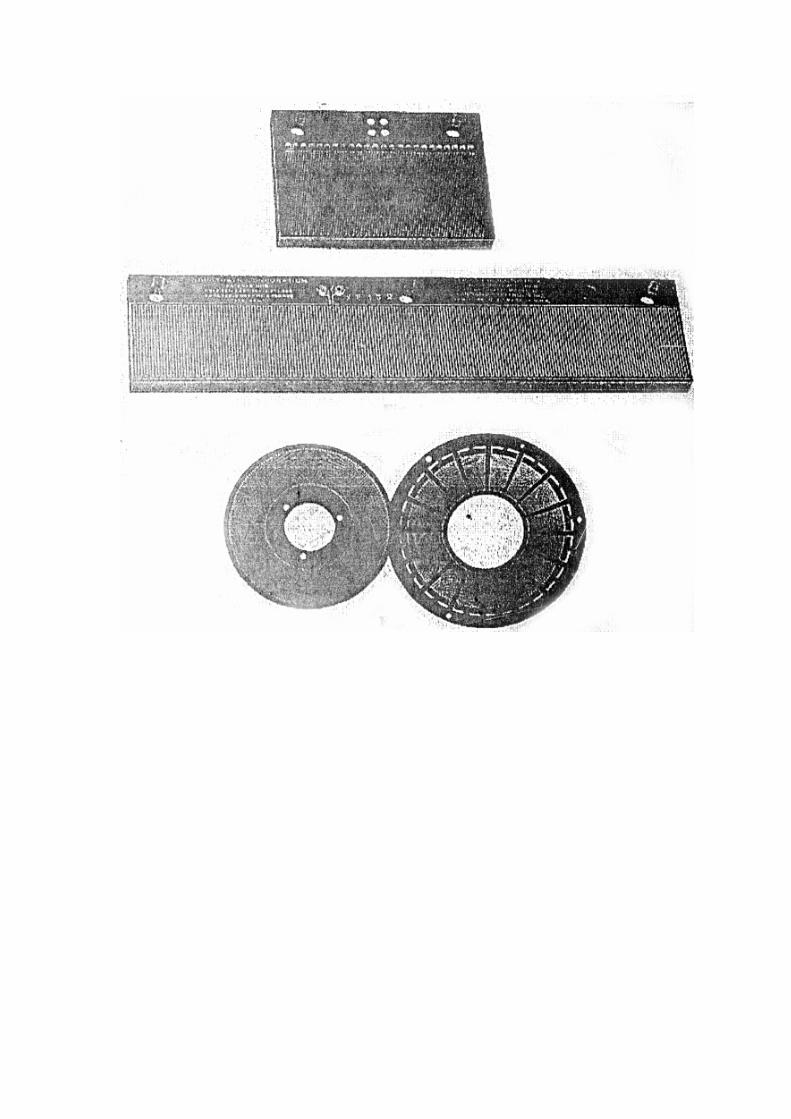
INTRODUCTION TO PROGRAMMABLE LOGIC
CONTROLLERS (PLC) PLC AND LADDER DIAGRAMS
INTRODUCTION The word PLC stands for Programmable Logic Controllers. Also some manufacturers use the name “PMC’ which stands for Programmable Machine Controllers. PLC normally consists of a standard hardware built by one manufacturer but used by different Original Equipment Manufacturer’s (OEM) to achieve the own sequence by programming. These have replaced the relay logic for the following applications. 1. Elevators 2. Washing machines 3. Process control 4. Special purpose machines 5. General purpose machines 6. Transfer lines As the name suggests these are field programmable and more flexible than the normal relay logic which were being used. Time spent for the modification of the sequence will also be less since the modification is a software modification and not hardware modification. Also PLC provide enhanced functions. These functions include counters, timers and Analog inputs and outputs. Counters and timers are available both in hardware version and software version. PLCs reduce the hardware connections since the actual logic is software, thus enhancing the reliability of the system it is also easy to connect peripherals like Computers, etc., for communication, data storage and display. PLCs play a vital role in CNC machines as window between the CNC control and the machine. This enables the machine builder to configure his own logic so that the required machine functions can be achieved. This type of window concept allows the system to have standard hardware configuration standardization of the hardware results in improved reliability. Ladder diagram is one of the methods used to program the PLC’s . Thus this is nothing but the Programme written by the OEM to control the sequence as per his
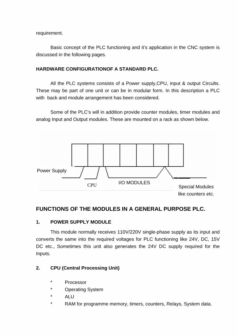
requirement. Basic concept of the PLC functioning and it’s application in the CNC system is discussed in the following pages. HARDWARE CONFIGURATIONOF A STANDARD PLC. All the PLC systems consists of a Power supply,CPU, input & output Circults. These may be part of one unit or can be in modular form. In this description a PLC with back and module arrangement has been considered. Some of the PLC’s will in addition provide counter modules, timer modules and analog Input and Output modules. These are mounted on a rack as shown below.
Power Supply
I/O MODULES Special Modules like counters etc.
CPU
FUNCTIONS OF THE MODULES IN A GENERAL PURPOSE PLC. 1. POWER SUPPLY MODULE
This module normally receives 110V/220V single-phase supply as its input and converts the same into the required voltages for PLC functioning like 24V, DC, 15V DC etc., Sometimes this unit also generates the 24V DC supply required for the Inputs. 2. CPU (Central Processing Unit) * Processor * Operating System * ALU * RAM for programme memory, timers, counters, Relays, System data.

* Serial port * Plug in memory module. Processor is the actual control equipment which works based on the operating system. As per the operating system it calls the control programme in a specified manner and executes the same. 1.7 Plug in memory module Plug in memory module is used to, store the control program and associated data in non volatile memory. 1.3 Operating System Operating system is the executive programme written by the PLC manufacturer which directs the functioning of CPU. 1.4 ALU (Arithmetic Logic Unit) ALU is used for processing the data which is byte long and word long. 1.5 RAM
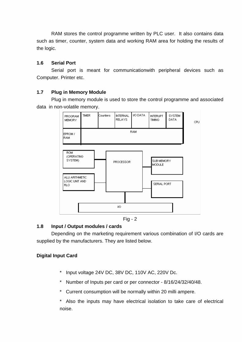
RAM stores the control programme written by PLC user. It also contains data such as timer, counter, system data and working RAM area for holding the results of the logic. 1.6 Serial Port Serial port is meant for communicationwith peripheral devices such as Computer. Printer etc. 1.7 Plug in Memory Module Plug in memory module is used to store the control programme and associated data in non-volatile memory.
Fig - 2
1.8 Input / Output modules / cards Depending on the marketing requirement various combination of I/O cards are supplied by the manufacturers. They are listed below. Digital Input Card
* Input voltage 24V DC, 38V DC, 110V AC, 220V Dc.
* Number of Inputs per card or per connector - 8/16/24/32/40/48.
* Current consumption will be normally within 20 milli ampere.
* Also the inputs may have electrical isolation to take care of electrical noise.

* Normally these input units have built in delay to take care of the contact bouncing of the limit switches.
Digital Output ard. * Input voltage 24V DC, 38V DC, 110V AC, 220V Dc.
* Number of Inputs per card or per connector - 8/16/24/32
* Current rating - 200 mA/500 mA/1A/2A
* Builtin protection - Available in higher current modules. 1.9 Special modules like timer modules, counter modules and analog modules are used for specific functions as the name suggests. 2. Ladder Diagram All PLC’s need a control program which is written by OEM. This programme can be written in different languages. They are. Satement List; Ladder diagram; Control flow chart; Higher level languages. In some cases all the above languages can be used for the same PLC. Each of the languages is explained below. 2.1. Statement List. Language used in this case is Boolean language. Here each instruction in PLC is written as one statement along with the data shown below. Load Io. (Limit switch 1) And I1 (Limit switch 2) And not I2 (Limit switch 3) Write O1 (Solenoid 1)
In the above case ‘I’ stands for Input and ‘O’ stands for output.
This equation informs the PLC that it limit switch 1 and 2 are closed and if limit switch 3 is not operated then switch on Solenoid 1.
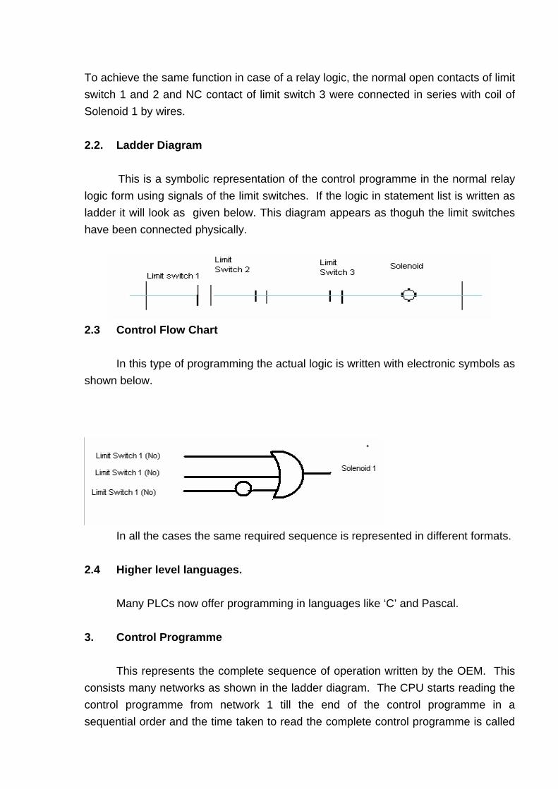
To achieve the same function in case of a relay logic, the normal open contacts of limit switch 1 and 2 and NC contact of limit switch 3 were connected in series with coil of Solenoid 1 by wires. 2.2. Ladder Diagram This is a symbolic representation of the control programme in the normal relay logic form using signals of the limit switches. If the logic in statement list is written as ladder it will look as given below. This diagram appears as thoguh the limit switches have been connected physically.
2.3 Control Flow Chart In this type of programming the actual logic is written with electronic symbols as shown below.
In all the cases the same required sequence is represented in different formats. 2.4 Higher level languages. Many PLCs now offer programming in languages like ‘C’ and Pascal. 3. Control Programme This represents the complete sequence of operation written by the OEM. This consists many networks as shown in the ladder diagram. The CPU starts reading the control programme from network 1 till the end of the control programme in a sequential order and the time taken to read the complete control programme is called
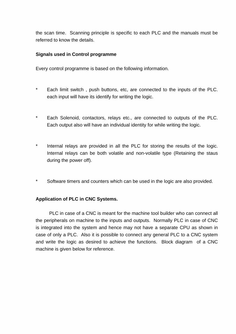
the scan time. Scanning principle is specific to each PLC and the manuals must be referred to know the details. Signals used in Control programme Every control programme is based on the following information.
* Each limit switch , push buttons, etc, are connected to the inputs of the PLC. each input will have its identify for writing the logic.
* Each Solenoid, contactors, relays etc., are connected to outputs of the PLC. Each output also will have an individual identity for while writing the logic.
* Internal relays are provided in all the PLC for storing the results of the logic. Internal relays can be both volatile and non-volatile type (Retaining the staus during the power off).
* Software timers and counters which can be used in the logic are also provided.
Application of PLC in CNC Systems. PLC in case of a CNC is meant for the machine tool builder who can connect all the peripherals on machine to the inputs and outputs. Normally PLC in case of CNC is integrated into the system and hence may not have a separate CPU as shown in case of only a PLC. Also it is possible to connect any general PLC to a CNC system and write the logic as desired to achieve the functions. Block diagram of a CNC machine is given below for reference.
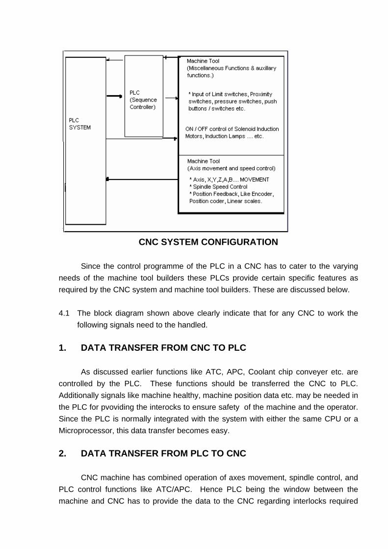
CNC SYSTEM CONFIGURATION
Since the control programme of the PLC in a CNC has to cater to the varying needs of the machine tool builders these PLCs provide certain specific features as required by the CNC system and machine tool builders. These are discussed below. 4.1 The block diagram shown above clearly indicate that for any CNC to work the
following signals need to the handled. 1. DATA TRANSFER FROM CNC TO PLC As discussed earlier functions like ATC, APC, Coolant chip conveyer etc. are controlled by the PLC. These functions should be transferred the CNC to PLC. Additionally signals like machine healthy, machine position data etc. may be needed in the PLC for pvoviding the interocks to ensure safety of the machine and the operator. Since the PLC is normally integrated with the system with either the same CPU or a Microprocessor, this data transfer becomes easy. 2. DATA TRANSFER FROM PLC TO CNC CNC machine has combined operation of axes movement, spindle control, and PLC control functions like ATC/APC. Hence PLC being the window between the machine and CNC has to provide the data to the CNC regarding interlocks required
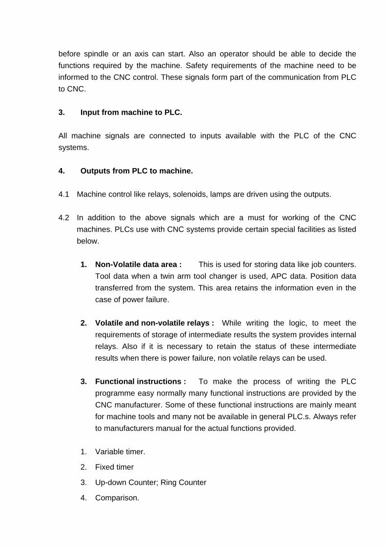
before spindle or an axis can start. Also an operator should be able to decide the functions required by the machine. Safety requirements of the machine need to be informed to the CNC control. These signals form part of the communication from PLC to CNC. 3. Input from machine to PLC. All machine signals are connected to inputs available with the PLC of the CNC systems. 4. Outputs from PLC to machine. 4.1 Machine control like relays, solenoids, lamps are driven using the outputs. 4.2 In addition to the above signals which are a must for working of the CNC
machines. PLCs use with CNC systems provide certain special facilities as listed below.
1. Non-Volatile data area : This is used for storing data like job counters.
Tool data when a twin arm tool changer is used, APC data. Position data transferred from the system. This area retains the information even in the case of power failure.
2. Volatile and non-volatile relays : While writing the logic, to meet the
requirements of storage of intermediate results the system provides internal relays. Also if it is necessary to retain the status of these intermediate results when there is power failure, non volatile relays can be used.
3. Functional instructions : To make the process of writing the PLC
programme easy normally many functional instructions are provided by the CNC manufacturer. Some of these functional instructions are mainly meant for machine tools and many not be available in general PLC.s. Always refer to manufacturers manual for the actual functions provided.
1. Variable timer.
2. Fixed timer
3. Up-down Counter; Ring Counter
4. Comparison.

5. Addition
6. Shorter direction for tool magazines.
7. Data search from tool magazine.
8. Parity check
9. Jump
10. Codification
11. Message display etc. 4.3. SCANNING PLC in case of CNC also works based on the control programme. However in most of the controls two scanning systems are provided. These are listed below. 1. Interrupt Scanning or Short term scanning. 2. Normal scanning of the signals. During interrupt scanning or short scanning time the status of the signals from the machine is read immediately on observing the change of the signals. During normal scanning the I/Odata is transferred at the beginning other the scanning of the program. All the details given here deal in general about the PLC used in any CNC SYSTEM. However it is always necessary to refer to the manufacturers manuals for complete details. Comparison of signals in FANUC and SIEMENS controls.
FAUNC SIEMENS
Input Address X... I....
CNC to PLC Signals F.... I...
PLC to CNC signals G... Q....
Output Address Y... Q....
Internal relay (Volatile) R... F...
Internal relay (Non-volatile) D/K... F....
Data Storage D... D/W...
Counters D/C... C....
Timers D/T.... T....
Role of PLC in CNC Systems
F MACHINE TOOL FUNCTIONS CONTROLLED BY PLC ARE
- Miscellaneous Functions
- Spindle Functions
- Tool Functions
F INPUTS TO PLC ARE
- Switching Elements on the Machine
- Switches / Push Buttons on control panel
- M, S, & T codes in Part program
F OUTPUTS CONTROLLED BY PLC CAN BE
- Contactors
- Solenoid Valves
- Electro-Magnetic Clutches
- Lamps, etc.
F TYPES OF PLCS IN CNC SYSTEMS
- Integrated
- External
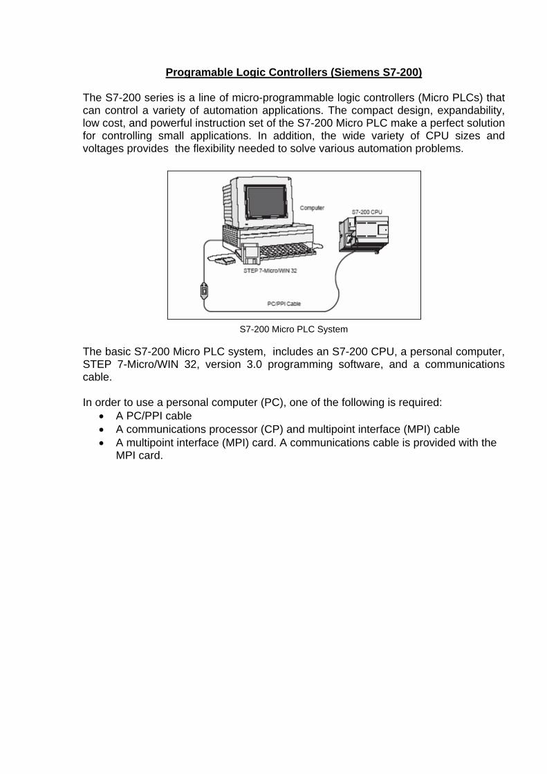
Programable Logic Controllers (Siemens S7-200)
The S7-200 series is a line of micro-programmable logic controllers (Micro PLCs) that can control a variety of automation applications. The compact design, expandability, low cost, and powerful instruction set of the S7-200 Micro PLC make a perfect solution for controlling small applications. In addition, the wide variety of CPU sizes and voltages provides the flexibility needed to solve various automation problems.
S7-200 Micro PLC System
The basic S7-200 Micro PLC system, includes an S7-200 CPU, a personal computer, STEP 7-Micro/WIN 32, version 3.0 programming software, and a communications cable. In order to use a personal computer (PC), one of the following is required:
• A PC/PPI cable • A communications processor (CP) and multipoint interface (MPI) cable • A multipoint interface (MPI) card. A communications cable is provided with the
MPI card.
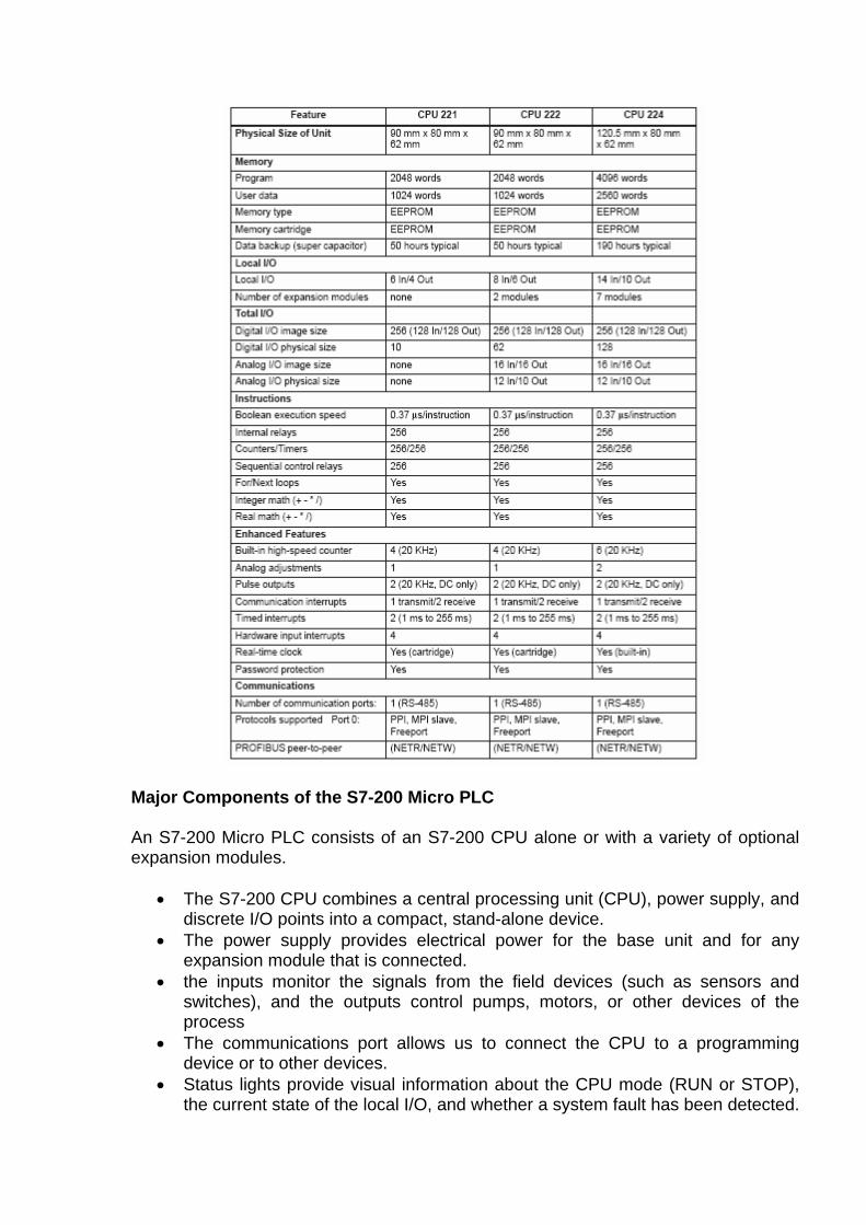
Major Components of the S7-200 Micro PLC An S7-200 Micro PLC consists of an S7-200 CPU alone or with a variety of optional expansion modules.
• The S7-200 CPU combines a central processing unit (CPU), power supply, and discrete I/O points into a compact, stand-alone device.
• The power supply provides electrical power for the base unit and for any expansion module that is connected.
• the inputs monitor the signals from the field devices (such as sensors and switches), and the outputs control pumps, motors, or other devices of the process
• The communications port allows us to connect the CPU to a programming device or to other devices.
• Status lights provide visual information about the CPU mode (RUN or STOP), the current state of the local I/O, and whether a system fault has been detected.
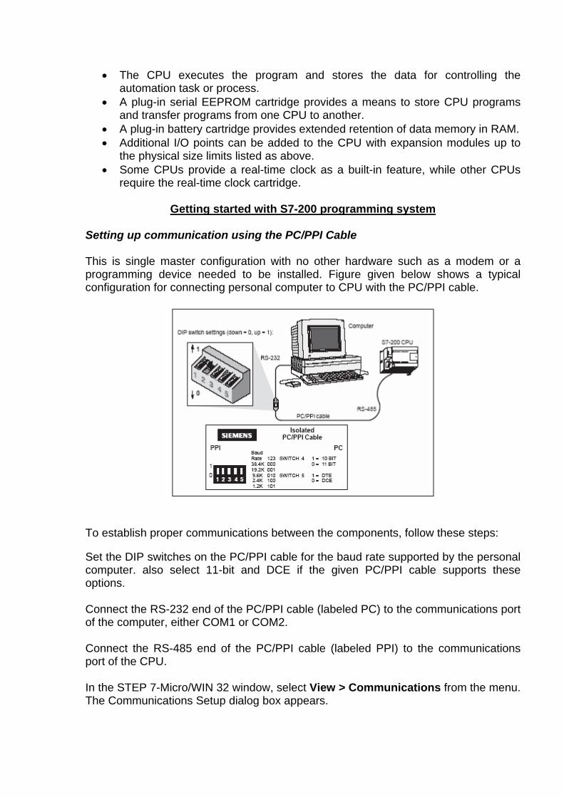
• The CPU executes the program and stores the data for controlling the automation task or process.
• A plug-in serial EEPROM cartridge provides a means to store CPU programs and transfer programs from one CPU to another.
• A plug-in battery cartridge provides extended retention of data memory in RAM. • Additional I/O points can be added to the CPU with expansion modules up to
the physical size limits listed as above. • Some CPUs provide a real-time clock as a built-in feature, while other CPUs
require the real-time clock cartridge.
Getting started with S7-200 programming system Setting up communication using the PC/PPI Cable This is single master configuration with no other hardware such as a modem or a programming device needed to be installed. Figure given below shows a typical configuration for connecting personal computer to CPU with the PC/PPI cable.
To establish proper communications between the components, follow these steps: Set the DIP switches on the PC/PPI cable for the baud rate supported by the personal computer. also select 11-bit and DCE if the given PC/PPI cable supports these options. Connect the RS-232 end of the PC/PPI cable (labeled PC) to the communications port of the computer, either COM1 or COM2. Connect the RS-485 end of the PC/PPI cable (labeled PPI) to the communications port of the CPU. In the STEP 7-Micro/WIN 32 window, select View > Communications from the menu. The Communications Setup dialog box appears.
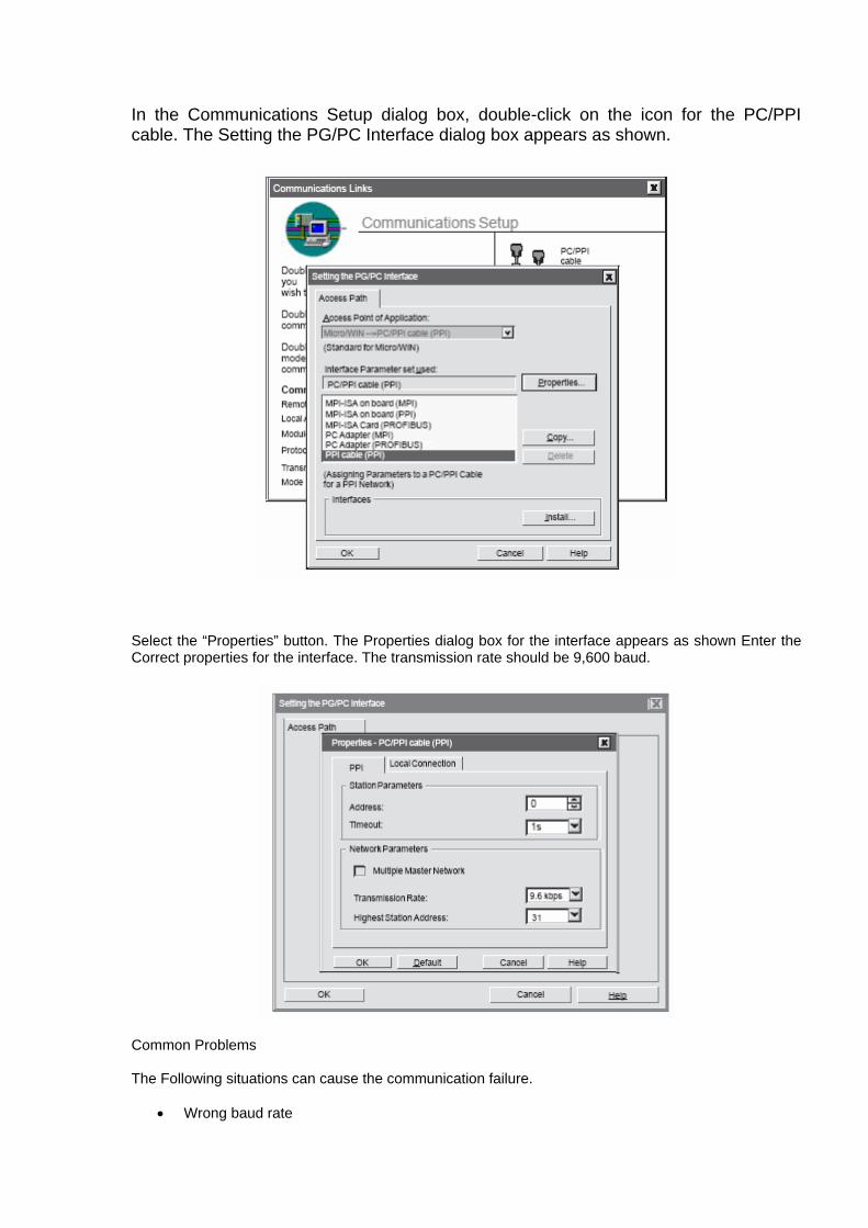
In the Communications Setup dialog box, double-click on the icon for the PC/PPI cable. The Setting the PG/PC Interface dialog box appears as shown.
Select the “Properties” button. The Properties dialog box for the interface appears as shown Enter the Correct properties for the interface. The transmission rate should be 9,600 baud.
Common Problems The Following situations can cause the communication failure.
• Wrong baud rate

• Wrong station address
• Incorrect DIP switch settings on PC/PPI cable
• Wrong communication port on PC
• Failure of PC/PPI cable
Going Online With the S7-200 CPU Steps to follow to go online with the S7-200 CPU: In the STEP 7-Micro/WIN 32 screen, click the Communications icon, or select View > Communications from the menu. The Communications Setup dialog box appears and shows that there are no CPUs connected. Double click the refresh icon in the Communications Setup dialog box. STEP 7-Micro/WIN 32 checks for any S7-200 CPUs (stations) that are connected. A CPU icon appears on the Communications Setup dialog box for each connected station. Double click the station that you want to communicate with. You will notice that the communication parameters on the Setup Communications dialog box reflects the parameters for the selected station.
You are now online with the S7-200 CPU. Changing the Communications Parameters for the PLC. To change the communications parameters follow the steps below:
1. select View > System Block from the menu.
2. The System Block dialog box appears. Click on the Port(s) tab.
3. By default, the station address is 2, and the baud rate is 9.6 kbaud.

4. Select “OK” to keep these parameters. If the parameters need to be changed then make
changes, then click the “Apply” button, then click “OK”.
5. Click the Download icon on the toolbar to load the changes into the PLC.
Basic Concepts for Programming an S7-200 CPU The basic operation of the S7-200 CPU is very simple: The CPU reads the status of the inputs.
The program that is stored in the CPU uses these inputs to evaluate the control logic.
As the program runs, the CPU updates the data.
Then it writes the data to the outputs
After that the CPU goes back continuously cycling through the program, reading and
writing.

Concepts of the S7-200 Programming Languages and Editors The S7-200 CPUs offer many types of instructions that allow you to solve a wide variety of automation tasks. STEP 7-Micro/WIN 32, provides different editor choices that allow you to create control programs with these instructions. While creating the programs the user has to select any one of the following editors
1. Statement List (STL)
2. Ladder Logic (LAD)
3. Function Block Diagram (FBD)
Statement List Editor(STL)
The STL editor allows us to create control program by entering the instruction
mnemonics. In STL Since we program in the native language of the CPU, rather than
in a graphical editor where some restrictions must be applied in order to draw the
diagrams correctly. Hence it allows us to create some programs that could not be
otherwise be created with LAD/FBD. In general the STL editor is more suitable for
experienced programmers who are familiar with PLCs and logic programming.
Example:
NETWORK
LD I0.0
LD I0.1
LD I2.0
A I2.1
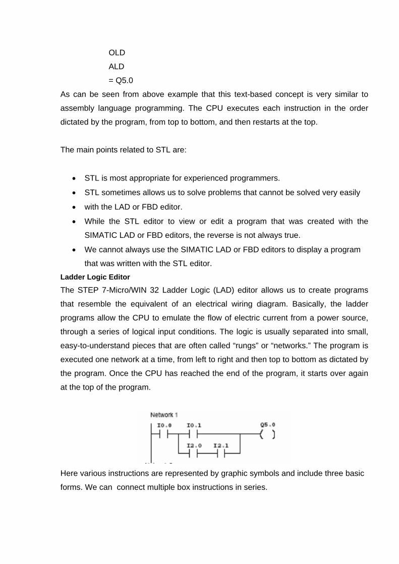
OLD
ALD
= Q5.0
As can be seen from above example that this text-based concept is very similar to
assembly language programming. The CPU executes each instruction in the order
dictated by the program, from top to bottom, and then restarts at the top.
The main points related to STL are:
• STL is most appropriate for experienced programmers.
• STL sometimes allows us to solve problems that cannot be solved very easily
• with the LAD or FBD editor.
• While the STL editor to view or edit a program that was created with the
SIMATIC LAD or FBD editors, the reverse is not always true.
• We cannot always use the SIMATIC LAD or FBD editors to display a program
that was written with the STL editor. Ladder Logic Editor
The STEP 7-Micro/WIN 32 Ladder Logic (LAD) editor allows us to create programs
that resemble the equivalent of an electrical wiring diagram. Basically, the ladder
programs allow the CPU to emulate the flow of electric current from a power source,
through a series of logical input conditions. The logic is usually separated into small,
easy-to-understand pieces that are often called “rungs” or “networks.” The program is
executed one network at a time, from left to right and then top to bottom as dictated by
the program. Once the CPU has reached the end of the program, it starts over again
at the top of the program.
Here various instructions are represented by graphic symbols and include three basic
forms. We can connect multiple box instructions in series.

Contacts - represent logic “input” conditions analogous to switches, buttons, internal
conditions and so on.
Coils - usually represent logic “output” results analogous to lamps, motor starters,
interposing relays, internal output conditions and so on.
Boxes - represent additional instructions such as timers, counters, or math
instructions.
The main points to consider while selecting the LAD editor are:
Ladder logic is easy for beginning programmers to use.
Graphical representation is often easy to understand, and is popular around the world.
we can always use the STL editor to display a program created with the LAD editor.
Function Block Diagram Editor(FBD) Function Block Diagram (FBD) editor allows us to view the instructions as logic boxes that resemble common logic gate diagrams. There are no contacts and coils as found in the LAD editor, but there are equivalent instructions that appear as box instructions. The program logic is derived from the connections between these box instructions. That is, the output from one instruction (such as an AND box) can be used to enable another instruction (such as a timer) to create the necessary control logic. This connection concept allows us to solve a wide variety of logic problems.
The main points to consider when you select the FBD editor are: The graphical logic gate style of representation is good for following program flow. We can always use the STL editor to display a program created with the SIMATIC FBD editor.
Basic Elements for Constructing a Program We create a program for controlling a particular process with STEP 7-Micro/WIN 32 and download it to the CPU. From the main program, we can call different subroutines or interrupt routines as per the requirement of the process. The CPU then continuously executes the program to control the task or process.
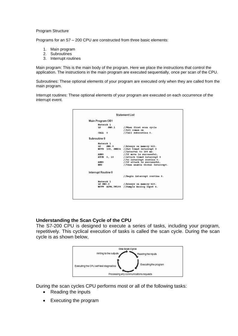
Program Structure Programs for an S7 – 200 CPU are constructed from three basic elements:
1. Main program 2. Subroutines 3. Interrupt routines
Main program: This is the main body of the program. Here we place the instructions that control the application. The instructions in the main program are executed sequentially, once per scan of the CPU. Subroutines: These optional elements of your program are executed only when they are called from the main program. Interrupt routines: These optional elements of your program are executed on each occurrence of the interrupt event.
Understanding the Scan Cycle of the CPU The S7-200 CPU is designed to execute a series of tasks, including your program, repetitively. This cyclical execution of tasks is called the scan cycle. During the scan cycle is as shown below,
During the scan cycles CPU performs most or all of the following tasks:
• Reading the inputs
• Executing the program

• Processing any communication requests
• Executing the CPU self-test diagnostics
• Writing to the outputs
The series of tasks executed during the scan cycle is dependent upon the operating mode of the CPU. The S7-200 CPU has two modes of operation, STOP mode
RUN mode. With respect to the scan cycle, the main difference between STOP and RUN mode is that in RUN mode program is executed, and in STOP mode it is not executed. Reading the Digital Inputs Each scan cycle begins by reading the current value of the digital inputs and then writing these values to the process-image input register called as PII registers.These PII registers are byte oriented.
MAINTENANCE OF CNC MACHINES
INTRODUCTION
Statistics on the utilisation of machine tools on an average revealed staggeringly low values - around 25% in India and upto 30% in the industrially developed countries. In other words, machine tool is cutting metal for about 25% of the available time only. In the rest of the 75% of the time, a portion of it is consumed for tool / job setups, changes, inspection, etc., but a lion’s share of it is attributed to breakdowns which make the machine utilisation is with conventional machines.
CNC machines are designed and built to give superior performance and accuracy when compared to conventional machine tools. Hence sophisticated items such as servo drives, ball lead screws, roller packs, curvic couplings, encoders, inductosyns, resolvers, etc., are used in CNC machine assembly resulting in increased cost of the equipment. Hence machine hour rate for these machines is high when compared to their conventional counterparts. Downtime of these machines should be reduced and kept to a minimum in order to achieve the economic advantages of CNC technology. Further repairing of CNC machine is very expensive, since most of the spares are costly and are not available indigenously and hence to be imported. The main objectives of CNC equipment maintenance are to: 1. Attempt to maximise dependable uptime.
2. Minimise repair time (downtime)
3. Maintain positional accuracy and repetitive tolerances.
4. To increase equipment’s service life.
In order to achieve the above objectives maintenance programme has to be well planned. A maintenance cell may be formed by drawing experienced people in the fields of mechanical engineering, hydraulic, electronics, and electrical engineering, to look after the various aspects of CNC maintenance.
1. CNC MACHINE TOOL ELEMENTS : CNC machines tool elements can be grouped into these categories. Vis.,
1. Machine elements
2. Hydraulic elements, and

3. Electrical and Electronic elements.
The general items under machine elements are:
a) Ball lead screws.
b) Ball bushings
c) Re-circulating roller packs and hardened, ground replaceable steel strips.
d) Lubrication elements.
e) Curvic couplings
f) Headstock, table assembly, rotary table, pallet changers etc.
The items under hydraulic elements are:
a) Servo valves
b) Servo drives
c) Power packs
d) Solenoid valves, relief valves, pressure switches etc.
e) Accumulators
f) Fittings, seals and packings etc.
g) Filters.
h) Hydraulic cylinders, motors etc.
The items under electrical and electronic elements:
a) Limit switches
b) Servo motors
c) Measuring system such as inductosyns, encoders, resolvers etc.
d) Relays, contactors, etc.
e) Tape reader, tape punching unit etc.
Daily preventive maintenance programme emphasizes oil checks and recording. This follows a general rule from the past experience that equipment using unusual quantities of oil may be in trouble. Hence operator has to check oil levels on the mist lube tank, hydraulic unit, oil level on axis gearboxes and coolant levels. Some equipment pressures (for example, compressed air line/hydraulic accumulator pre-charge pressure) are to be checked and recorded . These check up indicate equipment status.
Cleaning of the machine is also a preventive maintenance item. Lack of cleanliness on tool changer, gripper fingers, limit switches, strainers and tape reader

head can cause intermittent problems.
Weekly preventive maintenance emphasizes on checking for abnormal equipment performance, other than the quick visual checks for oil leaks and any line or hose breakage etc. It includes equipment cycle time such as tool transfer time, table index time feed rate and spindle speed rates. Other items are proper tool seating, emergency stops occuring under given conditions.
Monthly preventive maintenance may inlcude hydraulic oil analysis plus
cleaning, lubricating and adjusting of index/rotary table bearings and the collet clamping force of the spindle. Quarterly preventive maintenance may be as an extension or supplement monthly programmes. Quarterly programmes emphasize continued cleaning, lubrication and filter change. 3. DOCUMENTATION OF MAINTENANCE PROGRAMME:
Most preventive maintenance efforts and breakdown repair activities can be
greatly enhanced by proper documentation. For this purpose machine history cards, log books, status of spare parts inventory, test charts, performance cards, etc., are to be properly recorded on a standard format. These informations are very valuable for procurement of spares, repair and future maintenance. Computers can be used for processing the data, storing and retrieval of data whenever it is required. The main aim of computerizing is not just the automation of paper work, but more importantly, the compilation of records with meanings. Further computer system enables to track virtually every activity and analyze virtually every cost and soon enough to take corrective action when it is required.
Other documents like machine manuals, assembly drawings, hydraulic circuit diagrams, diagnostic tapes listings for diagnostic tapes etc., are to be kept in duplicate, so that one set as a master copy and other set may be with the concerned maintenance personnel. 4. SPARE PARTS
It is the responsibility of maintenance personnel to control and stocking of spare parts, required for the purpose of maintenance of the machines. The spare parts may be either bought out item or may be manufactured in the same plant depending on the complexity of spare parts. Sometime costly parts are to be reconditioned by adopting reclamation process like, hard chrome plating, welding, metalizing etc. in all above cases, they are to be very well planned in advance to reduce the breakdown time.
When spare parts are to brought due importance is to be given to imported
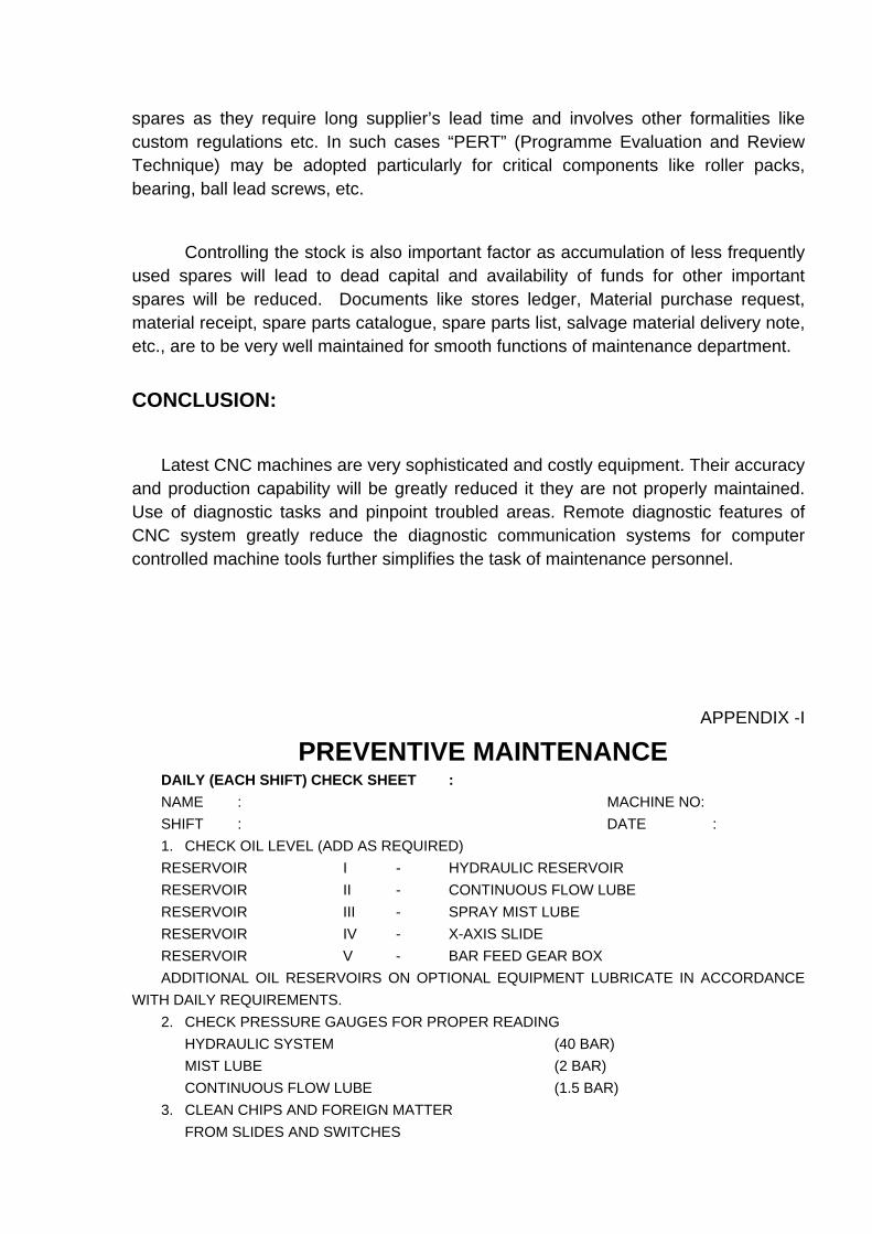
spares as they require long supplier’s lead time and involves other formalities like custom regulations etc. In such cases “PERT” (Programme Evaluation and Review Technique) may be adopted particularly for critical components like roller packs, bearing, ball lead screws, etc.
Controlling the stock is also important factor as accumulation of less frequently used spares will lead to dead capital and availability of funds for other important spares will be reduced. Documents like stores ledger, Material purchase request, material receipt, spare parts catalogue, spare parts list, salvage material delivery note, etc., are to be very well maintained for smooth functions of maintenance department.
CONCLUSION:
Latest CNC machines are very sophisticated and costly equipment. Their accuracy and production capability will be greatly reduced it they are not properly maintained. Use of diagnostic tasks and pinpoint troubled areas. Remote diagnostic features of CNC system greatly reduce the diagnostic communication systems for computer controlled machine tools further simplifies the task of maintenance personnel.
APPENDIX -I
PREVENTIVE MAINTENANCE DAILY (EACH SHIFT) CHECK SHEET : NAME : MACHINE NO: SHIFT : DATE : 1. CHECK OIL LEVEL (ADD AS REQUIRED) RESERVOIR I - HYDRAULIC RESERVOIR RESERVOIR II - CONTINUOUS FLOW LUBE RESERVOIR III - SPRAY MIST LUBE RESERVOIR IV - X-AXIS SLIDE RESERVOIR V - BAR FEED GEAR BOX ADDITIONAL OIL RESERVOIRS ON OPTIONAL EQUIPMENT LUBRICATE IN ACCORDANCE
WITH DAILY REQUIREMENTS. 2. CHECK PRESSURE GAUGES FOR PROPER READING HYDRAULIC SYSTEM (40 BAR) MIST LUBE (2 BAR) CONTINUOUS FLOW LUBE (1.5 BAR) 3. CLEAN CHIPS AND FOREIGN MATTER FROM SLIDES AND SWITCHES

4. CHIP PAN CLEANED (YES/NO) 5. MACHINE AND CABINET WIPED DOWN (YES/NO) 6. CABINET VENTILATING FAN OPERATING (YES/NO) 7. MOVE SLIDES MANUALLY FOR LONGEST POSSIBLE TRAVEL CHECK FOR PROPER LUBRICATION CHECK FOR NORMAL SLIDE OPERATION 8. VISUALLY INSPECT ALL TOOLS. 9. CONFIRM THAT MACHINE AND CONTROL ARE PROPERLY SET UP 10. CONFIRM THAT ALL GUARDS ARE IN PLACE AND THAT CONTROL DOORS ARE SHUT AND PROPERLY SECURED. 11. CHECK COOLANT SUPPLY IN RESERVOIR FLOW TO ROUND TURRET FLOW TO HEX TURRET 12. CHECK MACHINE CONTROL, UNIT (MCU) AS PER MANUFACTURERS SPECIFICATIONS. 13. CHECK TAPE READER AS PER MANUFACTURERS SPECIFICATIONS 14. RECORD AND FORWARD ANY MALFUNCTION TO PROPER PERSONNEL.
APPENDIX -I
PREVENTIVE MAINTENANCE
WEEKLY CHECK SHEET :
NAME : MACHINE NO:
SHIFT : DATE :
1. PERFORM DAILY CHECK
2. REVIEW DAILY CHECK SHEET AND
CHECK AND CORRECT ANY
MALFUNCTIONS REPORTED
3. LUBRICATE IN ACCORDANCE WITH
WEEKLY REQUIREMENTS.
4. BAR FEED UNIT (OPTIONAL)
SERVICE GREASE FITTINGS
STEADY REST
FRONT PUSHER

ADD OIL AS REQUIRED
SPEED REDUCER
DRIVE CHAIN.
5. INSPECT ALL CONDUIT CONNECTIONS
AND PUSH BUTTONS FOR TIGHTNESS
6. CHECK MACHINE CONTROL UNIT (MCU) AS PER
MANUFACTURERS SPECIFICATIONS
7. CHECK TAPE READER - AS PER MANUFACTURER’S
SPECIFICATIONS.
PREVENTIVE MAINTENANCE
MONTHLY CHECK SHEET : NAME : MACHINE NO:
SHIFT : DATE :
1. PERFORM DAILY AND WEEKLY CHECKS.
2. REVIEW THE DAILY AND WEEKLY CHECKS
CHECK AND CORRECT ANY MALFUNCTIONS REPORTED
3. SERVICE FILTERS - CLEAN AND/OR REPLACE AS REQUIRED
• IN-LINE LUBE FILTER
• MIST AIR FILTER
• MAGNETIC FILTER
• SYSTEM FILTER
• CONTROL CABINET AIR FILTER.
4. CHECK HYDRAULIC SYSTEM ACCUMULATOR FOR LEAKS.
5. CHECK ACCUMULATOR - CHARGE PRESSURE
6. CHECK FOR COOLANT LEAKING INTO OPERATORS
CONTROL. PANEL, JUNCTION BOXES AND MAIN
DRIVE MOTOR HOUSING.
7. REMOVE GUARD AND CLEAN FOREIGN MATTER
FROM ALL SURFACES PROTECTED BY THIS GUARD
8. CHECK WAY WIPERS
9. CHECK OPERATION OF “OUT-OF-LIMIT” SWITCHES
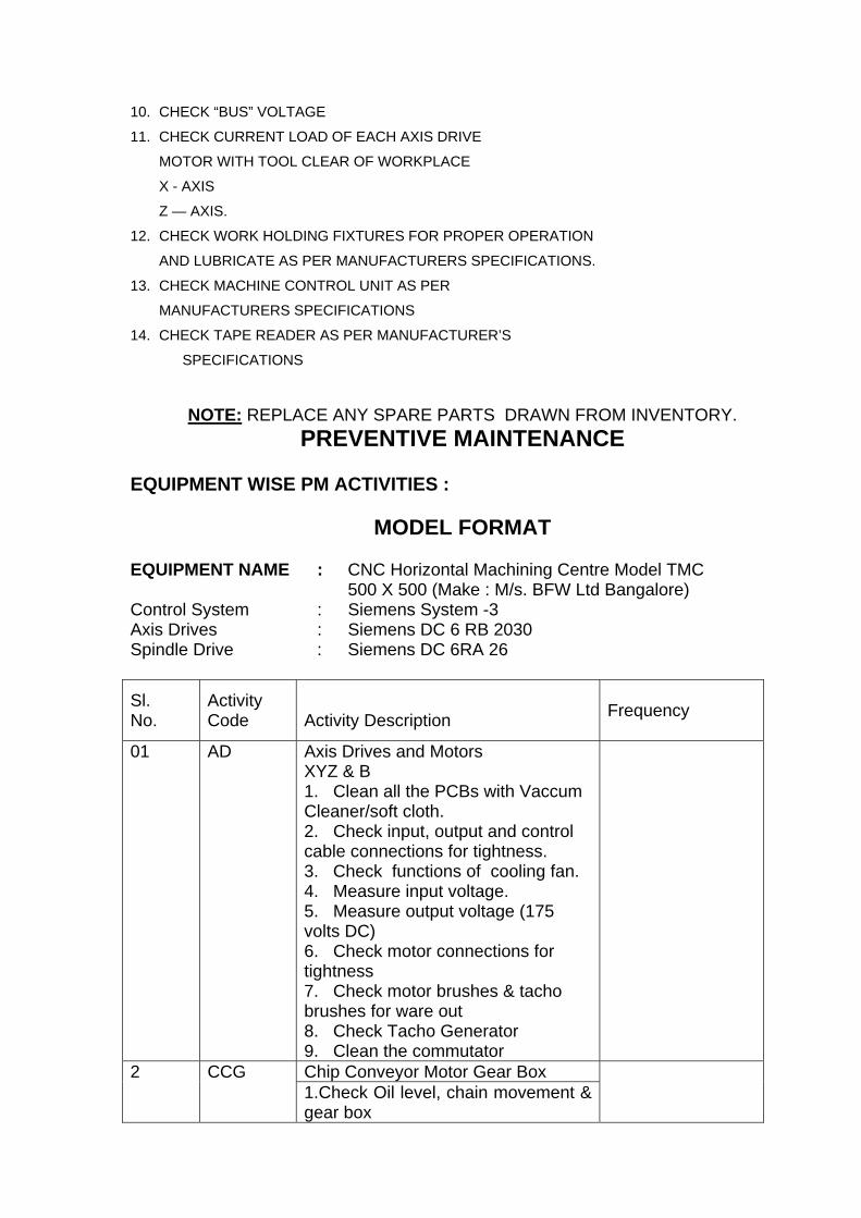
10. CHECK “BUS” VOLTAGE
11. CHECK CURRENT LOAD OF EACH AXIS DRIVE
MOTOR WITH TOOL CLEAR OF WORKPLACE
X - AXIS
Z — AXIS.
12. CHECK WORK HOLDING FIXTURES FOR PROPER OPERATION
AND LUBRICATE AS PER MANUFACTURERS SPECIFICATIONS.
13. CHECK MACHINE CONTROL UNIT AS PER
MANUFACTURERS SPECIFICATIONS
14. CHECK TAPE READER AS PER MANUFACTURER’S
SPECIFICATIONS
NOTE: REPLACE ANY SPARE PARTS DRAWN FROM INVENTORY. PREVENTIVE MAINTENANCE
EQUIPMENT WISE PM ACTIVITIES :
MODEL FORMAT EQUIPMENT NAME : CNC Horizontal Machining Centre Model TMC 500 X 500 (Make : M/s. BFW Ltd Bangalore) Control System : Siemens System -3 Axis Drives : Siemens DC 6 RB 2030 Spindle Drive : Siemens DC 6RA 26
Sl. No.
Activity Code
Activity Description Frequency
01 AD Axis Drives and Motors XYZ & B 1. Clean all the PCBs with Vaccum Cleaner/soft cloth. 2. Check input, output and control cable connections for tightness. 3. Check functions of cooling fan. 4. Measure input voltage. 5. Measure output voltage (175 volts DC) 6. Check motor connections for tightness 7. Check motor brushes & tacho brushes for ware out 8. Check Tacho Generator 9. Clean the commutator
Chip Conveyor Motor Gear Box 2 CCG 1.Check Oil level, chain movement & gear box
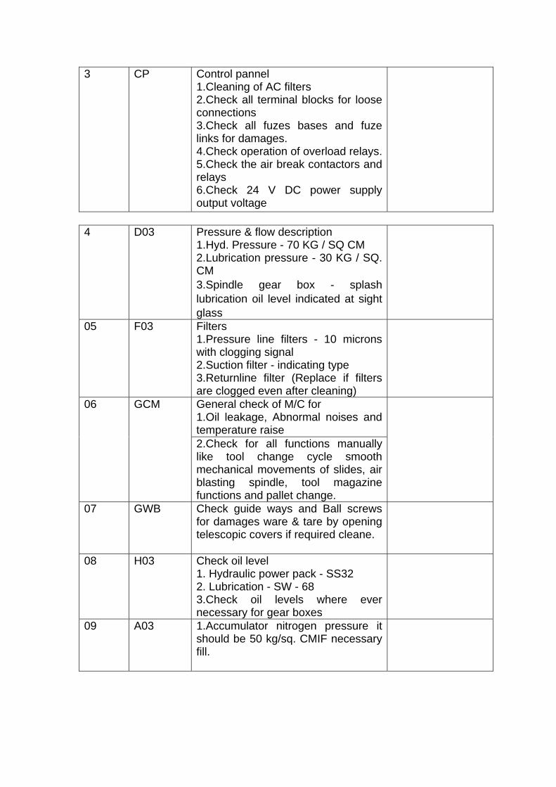
3 CP Control pannel 1.Cleaning of AC filters 2.Check all terminal blocks for loose connections 3.Check all fuzes bases and fuze links for damages. 4.Check operation of overload relays.5.Check the air break contactors and relays 6.Check 24 V DC power supply output voltage
4 D03 Pressure & flow description
1.Hyd. Pressure - 70 KG / SQ CM 2.Lubrication pressure - 30 KG / SQ. CM 3.Spindle gear box - splash lubrication oil level indicated at sight glass
05 F03 Filters 1.Pressure line filters - 10 microns with clogging signal 2.Suction filter - indicating type 3.Returnline filter (Replace if filters are clogged even after cleaning)
General check of M/C for 1.Oil leakage, Abnormal noises and temperature raise
06 GCM
2.Check for all functions manually like tool change cycle smooth mechanical movements of slides, air blasting spindle, tool magazine functions and pallet change.
07 GWB Check guide ways and Ball screws for damages ware & tare by opening telescopic covers if required cleane.
08 H03 Check oil level 1. Hydraulic power pack - SS32 2. Lubrication - SW - 68 3.Check oil levels where ever necessary for gear boxes
09 A03 1.Accumulator nitrogen pressure it should be 50 kg/sq. CMIF necessary fill.
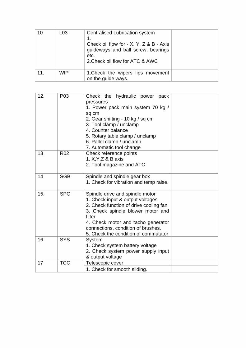
10 L03 Centralised Lubrication system 1. Check oil flow for - X, Y, Z & B - Axis guideways and ball screw, bearings etc. 2.Check oil flow for ATC & AWC
11. WIP 1.Check the wipers lips movement on the guide ways.
12. P03 Check the hydraulic power pack
pressures 1. Power pack main system 70 kg / sq cm 2. Gear shifting - 10 kg / sq cm 3. Tool clamp / unclamp 4. Counter balance 5. Rotary table clamp / unclamp 6. Pallel clamp / unclamp 7. Automatic tool change
13 R02 Check reference points 1. X,Y,Z & B axis 2. Tool magazine and ATC
14 SGB Spindle and spindle gear box 1. Check for vibration and temp raise.
15. SPG Spindle drive and spindle motor 1. Check input & output voltages 2. Check function of drive cooling fan 3. Check spindle blower motor and filter 4. Check motor and tacho generator connections, condition of brushes. 5. Check the condition of commutator
16 SYS System 1. Check system battery voltage 2. Check system power supply input & output voltage
Telescopic cover 17 TCC 1. Check for smooth sliding.