Embed Size (px)
Citation preview

Maintenance Manual
07/2012 MEGA
Pump Type:
Pump Serial Number:
Date:
Purchaser:
Purchaser’s Order Number:
GIW Work Order Number:
Shipped To:
Include the pump’s serial number when ordering replacement parts.
Note: This is a standard maintenance manual provided for your convenience. This manual may not be reproduced without written consent of GIW Industries.
Additional copies may be purchased. Please contact your sales representative for details.
GIW INDUSTRIES, INC. 5000 Wrightsboro Road
Grovetown, GA 30813 USA
+1 (888) 832-4449 FAX +1 (706) 855-5151 www.giwindustries.com
KSB AG Johann-Klein-Str. 9
D-67227 Frankenthal, Germany
+49 6233 86-0 . FAX +49 6233 86-3289
www.ksb.com
A KSB Company
MEGA
2
Contents
Section Page Section Page
1 General 3 2 Safety 3 2.1 Safety Instruction Markings 3 2.2 Personnel Qualification and Training 4 2.3 Non-compliance with Safety Instructions 4 2.4 Safety Awareness 4 2.5 Safety Instructions for the Operator/User 4 2.6 Safety Instructions for Maintenance, Inspection and
Installation 4 2.7 Unauthorized Modification and Manufacture of Spare
Parts 4 2.8 Unauthorized Modes of Operation 4 3 Design 5 3.1 Casing 5 3.2 Shaft 5 3.3 Shaft Sealing 5 3.3.1 Packing 5 3.3.2 Stuffing Box/Gland Packing 5 3.3.3 Gland Water Piping 5 3.3.4 Mechanical Seals 6 3.3.5 Transportation/Rigging 6 4 Installation 6 4.1 Base Grouting 6 4.1.1 Base Leveling 7 4.1.2 Grouting 7 4.2 Coupling Alignment 7 5 Piping Connections 7 5.1 Suction Pipe Installation 7 5.2 Discharge Pipe Installation 8 6 Operation 9 6.1 Initial Start-Up Procedure 9 6.2 Immediate Steps After Start-Up 9 7 Operational Inspection 10 7.1 Weekly Inspection 10 7.2 Monthly Inspection 10 7.3 Six (6) Month Inspection 10 7.4 Annual Inspection 10 8 Shutdown Procedure 10 9 Routine Maintenance 10 9.1 Bearings 10
9.2 Oil Lubrication 10 9.2.1 Oil Volume 11 9.2.2 Oil Quality 11 9.2.3 Lubrication Intervals 11 9.2.4 Oil Change Procedure 11 9.3 Shaft Seal Maintenance 12 9.3.1 Mechanical Seal Maintenance 12 9.3.2 Gland Packing Maintenance 12 10 Disassembly and Rebuild 12 10.1 Removal of Pump for Maintenance 13 10.1.1 Removal of Entire Pump Assembly 13 10.1.2 Removal of Mechanical End Only 13 11 Disassembly 13 11.1 Wet End 13 11.2 Mechanical End 13 11.3 Clean and Inspect Mechanical End Parts 14 11.4 Clean and Inspect Wet End Parts 14 12 Assembly 14 12.1 Mechanical End 14 12.1.1 Inpro Bearing Isolators and End Covers 14 12.1.2 End Covers 15 12.2 Wet End 15 13 Cold Weather Operation 15 14 Decommissioning and Storage 15 15 Troubleshooting 15 15.1 Low Flow Rate 16 15.2 Bearing Temperature 16 15.3 Bearing Contamination 16 15.4 Stuffing Box 16 15.5 Overheating of Pump Casing 16 15.6 Pump Leaking 16 15.7 Motor Overload 17 15.7.1 Vibrations or Abnormal Noises 17
ATTACHMENTS Sales Curve (Metric) 19 Sales Curve (U.S.) 20

MEGA
3
Attention: This maintenance manual contains very important information. It must be carefully and completely read before pump installation, electrical connection, first start-up or maintenance is performed.
1 General
Caution This manual contains important information for reliable, proper and efficient operation. Compliance with the
operating instructions is of vital importance to ensure reliability and long service life of the pump, and to avoid any risks. These operating instructions do not take into account local regulations, and it is the responsibility of the operator to ensure that such regulations are strictly observed by all, including the personnel called in for installation.
This pump / unit must not be operated beyond the limit values specified in the technical documentation for the medium handled, capacity, speed, density, pressure, temperature and motor rating. Make sure that operation is in accordance with the instructions given in this manual or in the contract documentation.
The GIW Mega Slurry is designed and manufactured with the latest technology. Due to its sturdy construction, it requires limited maintenance. For satisfactory and trouble free operation, it is recommended that this equipment be installed and cared for according to the instructions contained in this maintenance manual. This equipment must be used at operation conditions for which it has been designed, including flow rate, total head and pump rotating speed. When ordering spare parts or for additional information about this equipment, please indicate the type of pump and the serial number. This information can be obtained from the nameplate located on the top of the bearing housing.
Nameplate
2 Safety
These operating instructions contain fundamental information which must be complied with during installation, operation and maintenance of this equipment. Therefore, this operating manual must be read and understood by both the installation personnel and the responsible trained personnel/operators prior to installation and commissioning. This documentation must always be kept close to the operating location of the equipment for easy access. Additional copies may be purchased by contacting the GIW/KSB sales office. All general safety instructions given in this chapter of “Safety” must be complied with, as well as all the safety instructions outlined under specific headings.
2.1 Safety Instruction Markings
The safety instructions contained in this manual whose non-observance might cause hazards to persons are specially marked with the general hazard sign
Safety sign in accordance with DIN 4844-W9
The electrical danger warning sign is the safety sign in accordance with DIN 4844-W8.
The word caution is to introduce safety instructions whose non-observance may lead to damage to the machine and its functions.
Introduces safety instructions whose non-observance may lead to damage to the machine or its functions.
Caution
MEGA
4
Information attached directly to the machine, such as arrows indicating the direction of rotation, must always be complied with and be kept in legible condition at all times.
2.2 Personnel Qualification and Training
All personnel involved in the installation, operation, maintenance and inspection of the pump, motor, system and drive components must be fully qualified to carry out the work involved. Personnel responsibilities, competence and supervision must be clearly defined by the operator. If the personnel in question are not already in possession of the requisite know-how, appropriate training and instruction must be provided. If required, the operator may commission the manufacturer/supplier to provide such training. In addition, the operator is responsible for ensuring that the contents of the operating instructions are fully understood by the responsible personnel.
2.3 Non-compliance with Safety Instructions
Non-compliance with safety instructions can jeopardize the safety of personnel, the environment and the machine itself. Non-compliance with these safety instructions will also lead to forfeiture of any and all rights to claims for liability or damages. In particular, non-compliance could result in: Failure of important machine/unit functions Failure of prescribed maintenance and servicing practices Hazard to persons by electrical, mechanical and chemical effects Hazard to the environment due to leakage of hazardous substances.
2.4 Safety Awareness
It is imperative to comply with the safety instructions contained in this manual, the relevant national and local health and safety regulations and the operator’s own internal work, operation and safety regulations or codes.
2.5 Safety Instructions for the Operator/User
Any hot or cold components that could pose a hazard must be equipped with a guard by the operator. Guards which are fitted to prevent accidental contact with moving parts (e.g. coupling) must not be removed while the
machine is operating. Leakages at any point in the system of hazardous media (e.g. explosive, toxic, hot) must be contained to avoid any
danger to persons and the environment. Pertinent legal provisions must be adhered to. Electrical hazards must be eliminated. Refer to the relevant safety regulations applicable to different countries and/or the
local energy supply companies. 2.6 Safety Instructions for Maintenance, Inspection and Installation
The operator is responsible for ensuring that all maintenance, inspection and installation work is performed by authorized and qualified personnel who are thoroughly familiar with the manual. Work on the machine must be carried out only during standstill. The shutdown procedure described in the manual for taking the machine out of service must be adhered to without fail. Pumps or pump units handling media injurious to health must be decontaminated. Immediately following completion of the work, all safety/ protective devices must be re-installed and/or re-activated.
2.7 Unauthorized Modification and Manufacture of Spare Parts
Modifications or alterations of the machine are only permitted after consultation with the manufacturer. Original spare parts and accessories authorized by the manufacturer ensure safety. The use of other parts can invalidate any liability of the manufacturer for damage or warranty.
2.8 Unauthorized Modes of Operation
Any warranty of the operating reliability and safety of this equipment is only valid if the machine is operated in accordance with its designated use as described in the following sections. The limits stated in the data sheet must not be exceeded under any circumstances.
MEGA
5
3 Design
The pump is a horizontal, single stage, end suction and top discharge pump. The rear pull-out design allows maintenance of the mechanical end without dismantling the piping or affecting the alignment of the wet end.
3.1 Casing
The pump casing is horizontal volute casing, one piece casting with integral mounting foot.
3.2 Shaft
The shaft is dry design, protected by an easily renewable shaft sleeve in the gland sealing area. The impeller threads on the pump end of the shaft and a keyway is provided on the drive end to attach the coupling or pulley.
3.3 Shaft Sealing
The entry of the shaft into the pump is sealed by standard gland packing or by an optional mechanical seal.
3.3.1 Packing
The gland or stuffing box seals by means of renewable gland packing. The flush water circulation into the lantern ring performs the following functions: a) Lubricate and cool the packing b) Seal the packing against penetration of abrasive solid particles from the pump cavity c) Seal the stuffing box chamber against air penetration In certain clean fluid applications, the sealing liquid could be obtained from the pump discharge. Contact the factory for specific recommendations.
3.3.2 Stuffing Box/Gland Packing
The stuffing box is equipped with tapped holes for supplying flushing water. In order to keep the stuffing box free from abrasive particles, this water pressure and gland tightness should be adjusted to maintain a small flow of cool or lukewarm leakage out of the stuffing box while the pump is running. If the leakage becomes hot, the gland adjusting nuts should be loosened slightly to allow a greater flow. If cloudiness is seen in the leakage, more water pressure is needed. The gland should be adjusted during initial commissioning, and then readjusted as the packing breaks in during the first few hours of operation.
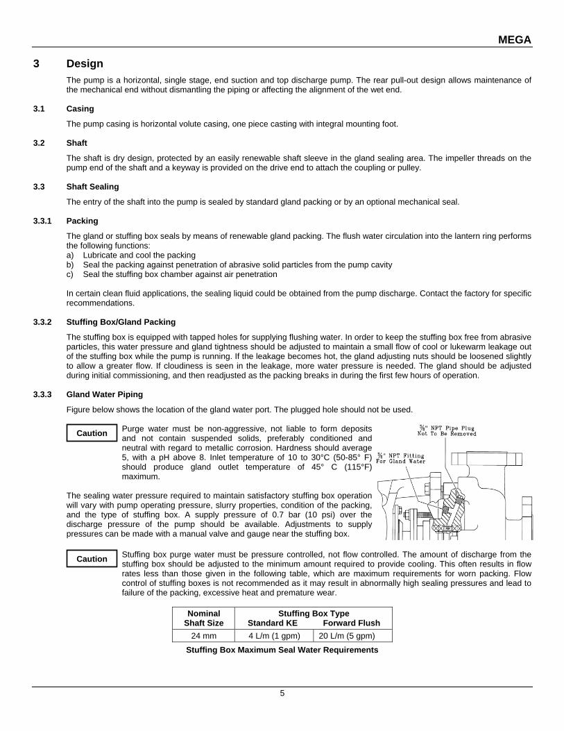
3.3.3 Gland Water Piping
Figure below shows the location of the gland water port. The plugged hole should not be used.
Purge water must be non-aggressive, not liable to form deposits and not contain suspended solids, preferably conditioned and neutral with regard to metallic corrosion. Hardness should average 5, with a pH above 8. Inlet temperature of 10 to 30°C (50-85° F) should produce gland outlet temperature of 45° C (115°F) maximum.
The sealing water pressure required to maintain satisfactory stuffing box operation will vary with pump operating pressure, slurry properties, condition of the packing, and the type of stuffing box. A supply pressure of 0.7 bar (10 psi) over the discharge pressure of the pump should be available. Adjustments to supply pressures can be made with a manual valve and gauge near the stuffing box.
Stuffing box purge water must be pressure controlled, not flow controlled. The amount of discharge from the stuffing box should be adjusted to the minimum amount required to provide cooling. This often results in flow rates less than those given in the following table, which are maximum requirements for worn packing. Flow control of stuffing boxes is not recommended as it may result in abnormally high sealing pressures and lead to failure of the packing, excessive heat and premature wear.
Nominal
Shaft Size Stuffing Box Type
Standard KE Forward Flush
24 mm 4 L/m (1 gpm) 20 L/m (5 gpm)
Stuffing Box Maximum Seal Water Requirements
Caution
Caution
MEGA
6
3.3.4 Mechanical Seals
Mechanical seals are manufactured in a variety of materials and styles, covering most different types of chemicals and liquids to be pumped. When the mechanical seal has been properly selected and installed correctly, it saves service time compared to packing seals. The mechanical seal consists of two ring faces. One is fixed in the housing and the second one rotates with the shaft, sliding against the fixed one. Their smooth contact surfaces are held against each other by spring pressure. The sealing of these faces is controlled by the selection of proper materials for the type of liquid being pumped. Two conditions are necessary for a long and safe operation of a mechanical seal. A film of liquid must be formed between the sliding surfaces and the heat generated by their friction should be absorbed by the circulation of liquids. Depending on the pumping conditions, this circulation may come from the liquid being pumped or from an external supply. Mechanical seals must never be run dry. Single seals in tight seal chambers require a circulation pipe from the pump housing to the seal to dissipate heat and to avoid deposits. Vent the seal chamber thoroughly before putting the mechanical seal into operation. Make sure the seal is completely immersed in liquid or there will be a risk of dry running. Additional instructions and/or the manufacturer’s manual will be included with the shipping documents.
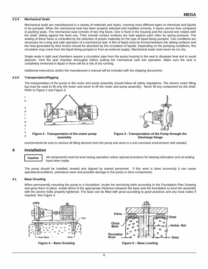
3.3.5 Transportation/Rigging
The transportation of the pump or the motor and pump assembly should follow all safety regulations. The electric motor lifting lug must be used to lift only the motor and never to lift the motor and pump assembly. Never lift any component by the shaft. Refer to Figure 2 and Figure 3. In corrosive environments be sure to remove all lifting devices from the pump and store in a non-corrosive environment until needed.
4 Installation
All components must be level during operation unless special provisions for bearing lubrication and oil sealing have been made.
The pump should be installed, leveled and aligned by trained personnel. If this work is done incorrectly it can cause operational problems, premature wear and possible damage to the pump or drive components.
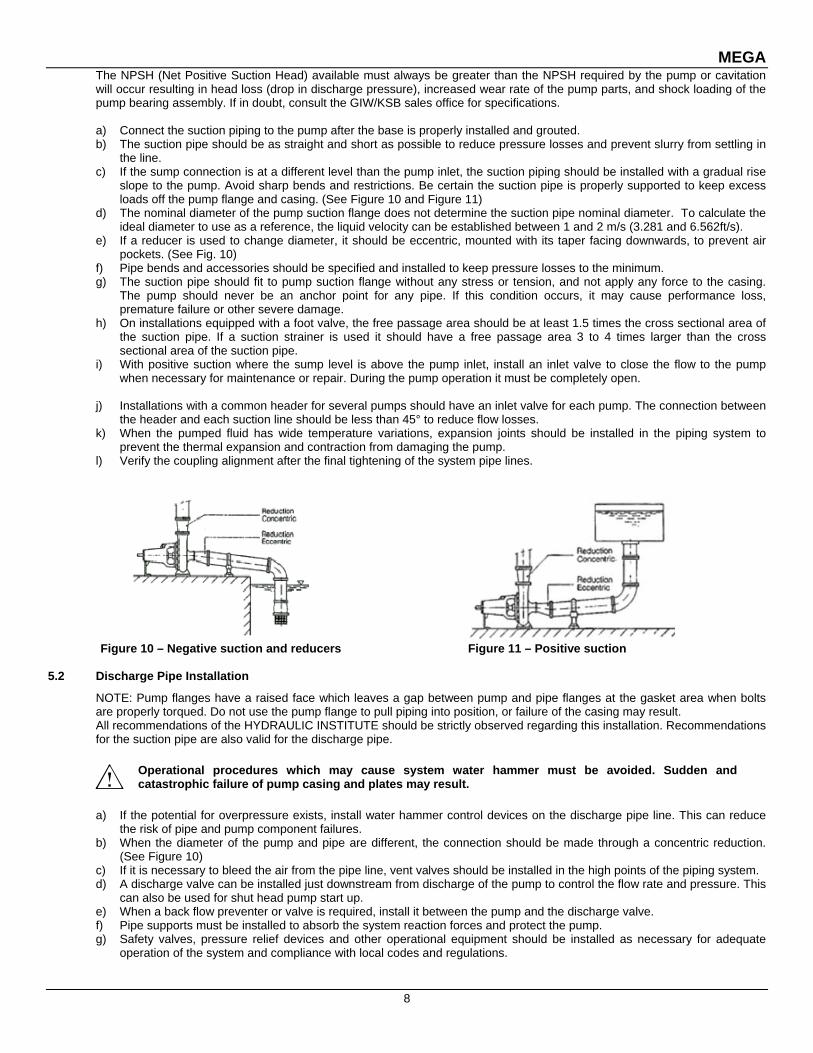
4.1 Base Grouting
When permanently mounting the pump to a foundation, locate the anchoring bolts according to the Foundation Plan Drawing and grout them in place. Install shims of the appropriate thickness between the base and the foundation to level the assembly with the anchor bolts properly tightened. The base can be filled with grout according to good practices and any local codes if required. See Figure 4.
Figure 2 - Transportation of the motor pump
assembly
Figure 3 - Transportation of the Pump through the
Discharge flange
Figure 4 – Base Grouting
Figure 5 – Base Leveling
Caution

MEGA
7
4.1.1 Base Leveling
Check to see if the base plate is resting evenly on the shims and tighten the nuts uniformly on the anchoring bolts. Using a precision level, check the level of the base longitudinally and transversally. If the base is not level, loosen the anchor nuts and insert shims between the foundation and the base until it is level. See Figure 5.
4.1.2 Grouting
In order to obtain solid and low vibration operation, the inner side of the base should be filled with grout. This grout should be prepared with a product that prevents contraction during the hardening process and provides sufficient fluidity to fill the base and displace air pockets. Epoxy grout is recommended. See Figure 6.
4.2 Coupling Alignment
Improper alignment of the unit can cause damage to both the coupling and the unit itself.
The useful life of the rotating assembly and its vibration free operation requires perfect alignment between the pump and the driver. Even when the unit is factory assembled, alignment must be rechecked after transportation and installation, since shipping and handling could alter it. With the pump completely installed and the grout set, perform the alignment with the suction and discharge pipelines already connected. This alignment should be performed with a dial indicator for the measurement of the radial and axial displacements. Attach the instrument to the motor coupling half, adjust the position of the probe perpendicular to the outside of the pump half of the coupling. Move the dial to zero and carefully rotate the motor coupling half and dial indicator a complete 360° turn, noting the readings at 90° intervals. Note that there may be reduced clearance between the coupling and the base or mounting plate. The same procedure should be performed to control the axial alignment. See Figure 7 and Figure 8. To correct the alignment, loosen the motor bolts and move it laterally or insert shims to correct its height as necessary. Axial and radial alignments should be within the total run out of 0.1mm (0.0039 inch) with the motor and pump mounting bolts tightened. NOTE: Be sure the clearance between the motor and pump shaft faces is within the coupling manufacturer’s specification. A straight edge may be used to check alignment on new couplings by placing it across the two rims of the coupling at 90° intervals. Shim the motor until the clearance under the straight edge is equal around the full circumference of the coupling. Axial clearance can be checked with a feeler gauge, making certain that both coupling faces are parallel and there is correct clearance between shafts. See Figure 9.
5 Piping Connections
Never use the pump itself as an anchorage point for the piping. The permissible pipeline forces for the flange size must not be exceeded.
5.1 Suction Pipe Installation
NOTE: Pump flanges have a raised face which leaves a gap between pump and pipe flanges at the gasket area when bolts are properly torqued. Do not use the pump flange to pull piping into position, or failure of the casing may result. All recommendations of the HYDRAULIC INSTITUTE should be strictly observed regarding this installation.
Figure 6 – Filling the base with grout
Figure 7 – Radial alignment
Figure 8 – Axial alignment
Figure 9 – Alignment with Straight Edge and Feeler
Gauge
Caution
MEGA
8
The NPSH (Net Positive Suction Head) available must always be greater than the NPSH required by the pump or cavitation will occur resulting in head loss (drop in discharge pressure), increased wear rate of the pump parts, and shock loading of the pump bearing assembly. If in doubt, consult the GIW/KSB sales office for specifications. a) Connect the suction piping to the pump after the base is properly installed and grouted. b) The suction pipe should be as straight and short as possible to reduce pressure losses and prevent slurry from settling in
the line. c) If the sump connection is at a different level than the pump inlet, the suction piping should be installed with a gradual rise
slope to the pump. Avoid sharp bends and restrictions. Be certain the suction pipe is properly supported to keep excess loads off the pump flange and casing. (See Figure 10 and Figure 11)
d) The nominal diameter of the pump suction flange does not determine the suction pipe nominal diameter. To calculate the ideal diameter to use as a reference, the liquid velocity can be established between 1 and 2 m/s (3.281 and 6.562ft/s).
e) If a reducer is used to change diameter, it should be eccentric, mounted with its taper facing downwards, to prevent air pockets. (See Fig. 10)
f) Pipe bends and accessories should be specified and installed to keep pressure losses to the minimum. g) The suction pipe should fit to pump suction flange without any stress or tension, and not apply any force to the casing.
The pump should never be an anchor point for any pipe. If this condition occurs, it may cause performance loss, premature failure or other severe damage.
h) On installations equipped with a foot valve, the free passage area should be at least 1.5 times the cross sectional area of the suction pipe. If a suction strainer is used it should have a free passage area 3 to 4 times larger than the cross sectional area of the suction pipe.
i) With positive suction where the sump level is above the pump inlet, install an inlet valve to close the flow to the pump when necessary for maintenance or repair. During the pump operation it must be completely open.
j) Installations with a common header for several pumps should have an inlet valve for each pump. The connection between the header and each suction line should be less than 45° to reduce flow losses.
k) When the pumped fluid has wide temperature variations, expansion joints should be installed in the piping system to prevent the thermal expansion and contraction from damaging the pump.
l) Verify the coupling alignment after the final tightening of the system pipe lines.
5.2 Discharge Pipe Installation
NOTE: Pump flanges have a raised face which leaves a gap between pump and pipe flanges at the gasket area when bolts are properly torqued. Do not use the pump flange to pull piping into position, or failure of the casing may result. All recommendations of the HYDRAULIC INSTITUTE should be strictly observed regarding this installation. Recommendations for the suction pipe are also valid for the discharge pipe.
Operational procedures which may cause system water hammer must be avoided. Sudden and catastrophic failure of pump casing and plates may result.
a) If the potential for overpressure exists, install water hammer control devices on the discharge pipe line. This can reduce
the risk of pipe and pump component failures. b) When the diameter of the pump and pipe are different, the connection should be made through a concentric reduction.
(See Figure 10) c) If it is necessary to bleed the air from the pipe line, vent valves should be installed in the high points of the piping system. d) A discharge valve can be installed just downstream from discharge of the pump to control the flow rate and pressure. This
can also be used for shut head pump start up. e) When a back flow preventer or valve is required, install it between the pump and the discharge valve. f) Pipe supports must be installed to absorb the system reaction forces and protect the pump. g) Safety valves, pressure relief devices and other operational equipment should be installed as necessary for adequate
operation of the system and compliance with local codes and regulations.
Figure 10 – Negative suction and reducers
Figure 11 – Positive suction

MEGA
9
6 Operation
6.1 Initial Start-Up Procedure
For new and rebuilt pumps a) Verify the pump and motor are correctly mounted, with all bolts properly torqued. b) Fill the bearing housing with the proper quantity and quality of oil as specified under the “Bearing Maintenance” section. c) Connect the suction and discharge pipe lines. d) Connect gland water and other auxiliary piping. e) Connect any gauges and monitoring devices. f) Connect the electrical wiring, checking that all motor protection devices are working and set correctly.
Electrical equipment operated in hazardous locations must comply with the applicable explosion protection regulations. This is indicated on the motor rating plate. If the equipment is installed in hazardous locations, the applicable local explosion protection regulations and the regulations of the test certificate supplied with the equipment and issued by the responsible approval authorities must be observed and complied with. The test certificate must be kept close to the location of operation as required by local or operator regulations.
g) With the coupling disconnected, verify the motor rotation direction. This will prevent reverse rotation that could damage
the pump.
Running in the wrong direction of rotation, even momentarily, may cause the impeller to unscrew and damage to the entire unit. Programmable VFD (Variable Frequency Drive) Controllers should have the Reverse function and any braking function disabled.
h) Check by hand that the pump shaft rotates freely. i) Connect the coupling and verify the coupling alignment is correct according to the “Coupling Alignment” section. Be sure
all fasteners are tight. j) Install the coupling guard and other safety devices. k) Prime the pump and the suction pipe with water or the liquid to be pumped, and bleed any air from the suction pipe and
pump. Centrifugal pumps cannot self prime.
Dry-running will result in increased wear on the gland packing and shaft protecting sleeve or failure of the mechanical seal and must be avoided!
l) Check that the gland adjustment nuts are just snug, and not overtightened. These will be adjusted later. m) Open the suction valve totally (if used) and close the discharge valve. n) Clear personnel and start the pump.
6.2 Immediate Steps After Start-Up
Be aware of rotating components and leakage of the pumped fluid from the gland.
Once the motor has reached its nominal speed, set the pump to its operation point of pressure and flow rate by slowly opening the discharge valve.
Prolonged operation against a closed shut-off element is not permitted. Danger of steam generation and explosion!
The pump should run quietly and free from vibrations at all times. Unusual noise or vibration should be investigated and corrected immediately. Use vibration evaluation criteria listed by the HYDRAULIC INSTITUTE for reference.
a) Check the motor power consumption to be sure it is within the correct range. Verify electric motor current and the network
voltages. b) VFD (Variable Frequency Drive) controllers should be adjusted to the correct setting for pump operation. c) Gland packing should be adjusted by tightening both gland cover nuts equally 1/6 of a turn at a time until the leakage rate
is slight drip. New packing will need time to break in and conform to the stuffing box. This adjustment should be checked periodically during the first 8 hours of operation. If dripping is excessive, tighten the gland cover nuts another 1/6 of a turn. During normal operation, gland packing should drip. Once the gland packing has broken in, a weekly control check is sufficient.
d) Verify that the suction pressure, discharge pressure and flow rate are the same as was calculated for the pump. e) Check the bearing temperature. It may reach 122° F (50°C) above ambient temperature; however, the sum of the bearing
temperature; plus the ambient temperature should not exceed 90°C (194° F).
Caution
Caution
Caution

MEGA
10
The previously listed items should be checked every 15 minutes during the first two hours of operation. If everything is normal, checks should be done every hour during the first 4 to 8 hours of operation. During this period, if any abnormalities are found, stop the pump if necessary and consult the “Troubleshooting” section of this manual.
7 Operational Inspection
The following routine inspection schedule is recommended. Severe operating or environmental conditions may require additional inspection or maintenance procedures. The operator is responsible for any additional inspections or intervals required.
7.1 Weekly Inspection
a) Operating conditions of the pump b) Head and flow c) Oil level at center of gauge with pump stopped d) Gland packing leakage and temperature e) Electric motor current consumption f) Electric network voltage g) Suction pressure h) Vibrations or abnormal noises i) Leaks from pump or piping j) Bearing Temperature
7.2 Monthly Inspection
In addition to regular checks: a) Oil change interval if required
7.3 Six (6) Month Inspection
a) Mounting bolts on the pump, driver and base b) Alignment of the motor-pump assembly c) Coupling lubrication if required d) Replace gland packing if necessary
7.4 Annual Inspection
Depending on actual operating time, the Mega pump should be completely inspected annually to insure long life. a) Disassemble the mechanical end for maintenance. b) Thoroughly clean all parts. c) Inspect the condition of bearings, shaft, Inpro™ seals d) Inspect wet end parts including internal areas of the volute casing, impeller and hub plate for thickness and wear. e) Inspect the coupling elements for wear. f) Replace parts as necessary and reassemble pump according to the Maintenance procedures in this manual.
8 Shutdown Procedure
To stop the pump, follow these instructions: a) Close the discharge valve. b) Switch off power to the motor and observe that the pump stops gradually and smoothly. c) Close the suction valve if present. d) Close any auxiliary pipe lines unless there are specific reasons not to. e) If pump maintenance will be performed, be sure any required Power Lock-outs are in place.
9 Routine Maintenance
9.1 Bearings
Mega Slurry pumps are “shipped dry” from the factory without oil in the bearing housing and must be filled with oil before rotating the pump
9.2 Oil Lubrication
Proper lubrication is the most critical factor for long service life. Since the units are shipped dry, the bearing assembly must be filled with oil before rotating or starting the pump. With the pump stopped, clean the area around the oil filler cap and fill the bearing housing to the centerline of the oil level sight gauge with the correct lubricant.
Caution

MEGA
11
9.2.1 Oil Volume
Do not overfill the bearing assembly. The capacities listed are approximate. When filling the bearing housing, the oil level must be at the centerline of the oil level sight glass when the shaft is not turning. This is the “cold level”, and will change as the pump runs and the oil becomes suspended in the bearings.
Bearing Assembly Approximate Oil CapacityA30 0.20 Liters (.25 Quarts)
9.2.2 Oil Quality
Use only clean, high quality lubricating oil designated for bearing service. These oils typically have high temperature stability, resistance to oxidation and foaming, and inhibit rust, corrosion, and the formation of deposits. Oils with EP additives are not generally recommended by the bearing manufacturers. Table 1 lists various brands of oil that could be used. Note that with the exception of GIW Blue, these are not tested by the factory but listed based on vendor published specifications. Be aware that different brands of oils contain additives that may not be compatible. Mixing them in service could cause a reaction that may be detrimental to the bearing assembly.
Manufacturer Up to 3,000 rpm Over 3000 rpm GIW Blue Atlantic Bardahl Castrol Esso Ipiranga Mobil Petrobras Royal Purple Shell Texaco
Blue 150 or 100 Eureka 68 Max Lub MA 20 Hyspin AWS 68 Turbine Oil 68 Ipitur AW-68 DTE 26 Marbrax TR 68 Syn-Film 68 Tellus 68 Regal R&O 68
Blue 100 Eureka 46 Max Lub MA 15 Hyspin AWS 46 Turbine Oil 46 Ipitur AW 46 DTE 24 Marbrax TR 46 Syn-Film 46 Tellus 46 Regal R&O 46
Table 1 – Lubricant Oil Specification
For applications with high ambient temperatures, severe loads or where extended oil change intervals are required, a synthetic lubricant should be used. GIW Blue is recommended for this duty. Contact the GIW/KSB sales office for details. Higher operating speeds or very cold ambient temperatures generally require the thinner viscosity (lower number) oil for proper lubrication.
9.2.3 Lubrication Intervals
The lubricating properties of oil diminish due to aging, heat and mechanical work. Lubricants become contaminated with metallic particles from normal bearing wear, plus dirt and moisture from the environment. That is the why oil must be changed at regular intervals. The first change should be done after the initial 100 to 200 hours of operation. This removes particles created during the break in cycle of the bearings. A second change should occur after 1,000 to 2,000 total hours. Depending on oil quality, change the oil after every 8,000 hours of effective operation or once a year, whichever comes first. The bearings should be inspected and cleaned every year or two, depending on service conditions.
9.2.4 Oil Change Procedure
Petroleum products may pose a health risk, so use proper precautions when changing oil. Collect and dispose of used oil in accordance with local regulations.
a) Clean the area around the oil filler and drain plugs. b) Place a container of at least 0.5 liter (0.5 qt) under the drain plug. c) Using a wrench, remove the pipe plug from the drain and allow the oil to drain into the container.
NOTE: Draining the oil into a paper filter or coffee filter will allow inspection for any unusual metal that could warn of possible bearing failure.
d) Clean the plug and reinstall in the drain.

MEGA
12
e) Add the correct amount of oil to bring the level to the center of the sight glass and replace the filler plug.
9.3 Shaft Seal Maintenance
9.3.1 Mechanical Seal Maintenance
If the pump is equipped with a mechanical seal, refer to the instructions for maintenance and repair provided by the seal manufacturer. If this information is not attached to the pump documentation, contact the local seal vendor or the GIW/KSB sales office.
9.3.2 Gland Packing Maintenance
The gland packing is a routine maintenance item that is consumed during pump service. After it has been compressed the equivalent of one packing ring thickness it will need replacement to avoid excess gland leakage. There are a number of packing materials available for different service requirements. Contact the GIW/KSB sales office for additional information. Gland packing can be renewed with the pump in place or during annual maintenance. a) Shut down the pump, close any system valves and lockout electrical service as required. b) Relieve any system pressure and drain the pump.
Pumped fluid will escape from the pump when the packing is removed. Necessary precautions must be taken if this fluid is hot or hazardous.
c) Remove the gland adjusting nuts. To remove the two piece gland cover, push it toward the bearing cover, and then
separate and remove the two halves. d) With a flexible packing tool, remove all the old packing rings and the lantern ring. e) Clean the stuffing box chamber. f) Check the condition of the shaft sleeve. If it is rough or grooved, it will damage the new packing and should be replaced.
Small surface imperfections can be removed by machining no more than 1 mm (0.039”) off the original diameter. The finished surface should be mirror smooth.
g) New packing is available directly from GIW/KSB in a package of precut rings. h) If rings are made from bulk material, cut the new packing on a 45 angle so the cut ends will mate when formed in a circle
around sleeve. (See Figure 12).
Figure 12 – Slanted cut of the packing rings
Figure 13 – Rings positioned with ends 90º from
each other
i) A compatible assembly lubricant, Molykote paste grease (molybdenum disulfide) or grease should be applied to the inside of the stuffing box or outer diameter of the packing, bushings and lantern ring to permit easier removal of packing for maintenance.
j) Coat the inner diameters of the packing and the outside of the shaft sleeve with the same lubricant used above. This will reduce wear on initial start up.
k) Reassemble in the opposite sequence of the disassembly, pressing each ring into the stuffing box chamber by using the gland cover.
l) The packing rings should be mounted with their ends 90 from each other (See Figure 13). The lantern ring must be in the proper location from the inner edge of the packing chamber.
m) After all the parts have been pressed into the stuffing box, install the gland cover with the adjusting nuts just snug. When the pump is started, tighten the nuts in equal increments of 1/6 of a turn (one flat) until the flow is reduced to a slight drip.
n) The gland should be adjusted to maintain a small flow of cool or lukewarm leakage out of the stuffing box while the pump is running. If the leakage becomes hot, loosen the gland slightly to allow a greater flow. If cloudiness is seen in the leakage, more water pressure is needed. The gland should be adjusted after replacement, and then readjusted as the packing breaks in during the first few hours of operation.
10 Disassembly and Rebuild
Mechanical end and bearing maintenance can be performed without removing the wet end pump casing from the piping system if desired. It is recommended that the entire pump be removed for the first rebuild in order to properly measure any wear inside the pump casing. Future maintenance procedures can be established once wear performance and wet end service life is determined for the specific application.

MEGA
13
10.1 Removal of Pump for Maintenance
The rear pull out design allows the option of removing the entire pump assembly or just the mechanical end. a) Shut down the pump, close any system valves and lockout electrical service as required. b) Relieve any system pressure and drain the pump.
Pumped fluid will escape from the pump when the packing is removed. Necessary precautions must be taken if this fluid is hot or hazardous.
10.1.1 Removal of Entire Pump Assembly
a) Disconnect and move the suction and discharge piping. b) Disconnect flush water at gland or seal connection. c) Disconnect the coupling from the motor. d) Remove fasteners holding pump to the base. e) Lift pump from the base.
10.1.2 Removal of Mechanical End Only
a) Suction and discharge piping can remain connected. b) Disconnect flush water at gland or seal connection. c) Disconnect the coupling from the motor. d) Remove motor from the base. e) Remove six (6) bolts attaching the mechanical end to the pump casing with a 6-point socket or box wrench. f) Remove two (2) fasteners attaching the rear end cover foot to the base. g) Carefully slide the bearing housing straight back until the impeller clears the back of the casing. h) Lift the assembly from the base. i) Replace fasteners to keep threads protected.
11 Disassembly
The Mega Slurry is designed as an economical service pump for limited duty. Depending on the time in service and overall condition, it may be better to replace the entire unit rather than rebuild it.
11.1 Wet End
a) Remove six (6) bolts attaching the mechanical end to the pump casing with a 6-point socket or box wrench and remove the pump casing.
b) Clamp the coupling hub to the work surface and remove the impeller by turning it in the direction of pump rotation. A strap wrench can be used around the perimeter, or a pry bar can be used between the vanes. It may be necessary to tap the handle with a hammer to break the impeller threads loose.
DO NOT APPLY HEAT TO IMPELLER! Danger of explosion exists due to sealed nose cavity.
c) Remove wear plate and stuffing box from the frame. d) Disassemble stuffing box glands, remove packing and lantern ring. e) Remove shaft sleeve from shaft
11.2 Mechanical End
a) Drain the oil as outlined in the “Oil Change Procedure” Section of this manual. b) Remove the coupling half and key from the shaft. c) Clean the exposed areas of the shaft so it can slide out of the Inpro bearing isolators. d) The Inpro bearing isolators should not be removed from the end covers unless they will be replaced with new ones due to
damage or leaking. e) Remove four (4) bolts attaching the drive end cover and mounting foot to the housing with a 6-point socket or box wrench
and slide the cover off the shaft. f) Remove four (4) bolts attaching the radial end cover to the housing and pull it off the housing. g) On the drive end, bend the tabs of the bearing lock nut out of the slots and remove the lock nut. h) Pull the shaft and bearing assembly out of the front of the housing. Be careful not to let the thrust bearings fall out. Mark
the position and direction of these bearings if they will be reused. i) If the radial bearing requires replacement, remove it from the shaft using a bearing puller if necessary.
MEGA
14
11.3 Clean and Inspect Mechanical End Parts
a) Any part that shows signs of wear or damage must be replaced. b) Using appropriate safety precautions, clean all parts with approved solvent and dry with compressed air. c) Bearings should be checked for wear on the races and rollers. Replace bearing if it does not rotate smoothly, or there is
any indication of wear or damage. d) Check the bearing bores in the housing for signs of wear or bearing rotation. e) Inspect shaft for wear, corrosion or thread damage. f) Shaft sleeves are normally replaced at any rebuild. g) Inpro bearing isolators should rotate freely. If oil leakage was evident prior to teardown, or if there was contamination
present inside the housing, the Inpro may be damaged and should be replaced. Otherwise, check the shaft o-ring and replace if damaged.
h) Check the drive end cover mounting foot for cracks or signs of mounting problems. i) Check the o-rings on the oil filler plug.
11.4 Clean and Inspect Wet End Parts
a) Remove packing and lantern rings from the stuffing box as outlined in the “Routine Maintenance” section. b) Clean the inner bore of the stuffing box. c) Clean flush water port and pipe threads. If there is any indication of mineral build up in the port, remove the top plug and
clean the bore. Replace the plug using thread sealant. d) Check the threads on the gland adjusting studs. e) All wet end parts must be inspected for both normal and unusual wear patterns. Pumps that operate away from the BEPQ
(best efficiency flow) will exhibit wear patterns that could shorten the life of the impeller or casing. Parts that are worn below 50% of the original thickness, or where areas of localized gouging are present, should be replaced at this time.
f) Check suction and discharge flanges for cracks at bolt area. This could indicate excess piping loads.
12 Assembly
Use proper tools and all safety precautions during the assembly procedure. Use the torque value for Lubricated Fasteners for each bolt size.
12.1 Mechanical End
a) Be sure all parts are completely clean. b) If the radial bearing is being replaced, heat it in an oil bath not to exceed 100C (212F). Secure the shaft vertically in a
vise with non-marking jaws and slide the bearing in place. Allow to cool. c) Coat all bearing rollers with oil. d) Place the two (2) thrust bearings in the housing and slide the shaft in from the pump end. e) Place the bearing lockwasher on the shaft with the tabs facing outward. f) Install and tighten the bearing lock nut. The shaft can be held in non-marking vise jaws at the keyway, or final torque can
be achieved after the impeller is installed. g) Bend one lock tab into a matching slot in the locknut. If necessary, tighten the nut further until a slot aligns. h) Place gaskets on the end covers.
12.1.1 Inpro Bearing Isolators and End Covers
a) The INPRO VBX seal consists of 2 pieces, but must NOT be disassembled. If the stator and rotor are separated, the o-ring may be cut and must be replaced.
b) Installation is easier if the Inpro is stored overnight in a freezer to reduce the diameter. The end cover can be warmed slightly to increase the bore diameter.
c) Lubricate the o-ring with a light coating of bearing oil. d) Align the seal in the end cover with the oil return groove and expulsion port located at the 6 o-clock (bottom) position. The
radial end cover should be clearly marked for assembly to the bearing housing. e) Gently press the seal into the end cover with a hand arbor press, using a block to distribute the load across the entire face
of the seal. It should slide easily into place without undue force. A drill press with a block of wood under the chuck will also work. The outer o-ring may shear slightly as it slides into the end cover. This is normal and will not cause a problem.
f) Lubricate the o-rings on the shaft bore with grease or bearing oil.

MEGA
15
12.1.2 End Covers
a) Before sliding the seal onto the shaft, wrap the shaft keyway with tape to prevent sharp edges from cutting the rotor drive o-ring. Lubricate the o-ring and shaft.
b) Gently slide the end cover over the shaft by pushing on the seal rotor face rather than the end cover. This prevents separating the unit or cutting the o-ring.
c) Align the end cover and check that the oil return groove and expulsion port on the inner face of the seal are located at the 6 o-clock (bottom) position.
d) Lightly lubricate the bolts with oil and install the end covers. e) Reinstall oil drain plug and filler cap. f) Reinstall the coupling half.
12.2 Wet End
If pump is equipped with a Mechanical Seal, refer to the instructions provided by the manufacturer for details on assembly and adjustment. a) Repack the stuffing box as outlined in “Routine Maintenance” Section. b) Assemble the gland follower and wear plate to the stuffing box. c) Coat the entire shaft with a light coat of anti-seize, grease or bearing oil to reduce corrosion. d) Install shaft sleeve. e) Slide the stuffing box assembly in place. f) Coat the shaft threads with anti-seize compound. g) Install the impeller Gasket. h) Thread the impeller on the shaft and tighten. i) Install the casing. Lightly lubricate and tighten the six (6) bolts connecting the casing to the bearing housing. j) Reinstall the pump. k) Add oil to the bearing assembly as outlined in the Routine Maintenance section. l) Install the motor and connect the coupling. m) Verify alignment according to the “Coupling Alignment” Section. n) Commission the pump as detailed in the “Operation” Section.
13 Cold Weather Operation
a) Pumps operated in cold conditions must be protected to prevent process fluid from freezing. Failure of pump casing or piping may result.
b) Gland flush water flow must be maintained. c) If mechanical seals are used, consult manufacturer for specific recommendations. d) Bearings must be protected from water contamination. e) Use of lighter viscosity oil is recommended.
14 Decommissioning and Storage
a) If the pump will be out of service for a prolonged period of time and there is any danger of freezing it should be completely drained.
b) Disconnect and drain the gland flush line. c) If the pump has a Mechanical Seal, refer to the seal manufacturer’s instructions for draining and storage. d) Rotate the shaft three (3) full turns by hand to coat the bearings with oil. This should be done monthly while the pump is
out of service to protect bearings from moisture and corrosion. e) Spray the exposed metal parts with a protective coating such as WD-40. f) Electrical service to the motor should be locked out. g) Tag pump to follow procedures listed in the “Operation, Initial Start Up” Section for recommissioning.
15 Troubleshooting
Mega Slurry pumps are designed to provide long, trouble free service if properly installed and maintained. Problems can be caused by the pipe system, changes in operating conditions or lack of routine maintenance. Information is provided here to help identify and cure most common issues encountered in slurry pump operation. If further assistance is needed, contact the GIW/KSB sales office with the pump serial number found on the nameplate. Actual system operating conditions, flow, head and power consumption, along with an accurate description of the problem, will help solve the problem. This section lists problems, causes and items to investigate. Correcting these items should rectify the problem.

MEGA
16
15.1 Low Flow Rate
a) Verify that the pump is correct for the system parameters in terms of flow and head. The pump curve can be used to determine the output, power and speed.
b) Depending on the age and service of the pump, parts could be worn sufficiently to reduce performance. c) Verify that the motor has the correct power and voltage required for the system, and is operating properly. d) Verify that the pump is running at the correct speed. e) Verify that the suction side has adequate NPSH (Net Positive Suction Head) as outlined in the “Suction Pipe Installation”
Section and pump specifications. f) Check the suction pipe for air pockets, leaks, partially closed valves or other restrictions. g) Be certain that the suction inlet and impeller are not clogged. h) Verify that the discharge valve is fully open.
15.2 Bearing Temperature
a) During the initial break in period, the bearings will normally run hotter as explained in the “Initial Start Up Procedures” Section.
b) Excess temperature due to hot process fluid c) Verify correct oil level. Overfilling causes viscous drag, which builds heat. d) Verify oil viscosity. High viscosity and mineral oils cause drag and build heat, especially at higher speeds. e) Misalignment of the motor or coupling can create excess bearing load and increased heat. f) Insufficient clearance between the pump shaft and motor shaft can add axial loads to the thrust bearings. g) External pipe forces can distort the pump and bind the bearings. h) Worn or damaged bearings may generate excess heat before failure. i) Drag from external parts such as guards.
15.3 Bearing Contamination
a) Excess leakage at stuffing box. b) Failed Inpro bearing isolator. c) Oil fill cap o-rings defective. d) Damaged or missing impeller gasket. e) End cover gasket damaged or missing.
15.4 Stuffing Box
See the “Packing” Section for procedures. a) Excess temperature due to packing adjusted too tight. b) Excess temperature due hot process fluid. c) Excess wear of packing or sleeve:
1. Adjusting the packing too tight. 2. Insufficient flush flow or pressure. 3. Contaminated flush water.
d) Leaking caused by wrong adjustment. e) Leaking caused by worn parts. f) Leaking caused by excess flush pressure.
15.5 Overheating of Pump Casing
See “Piping Connections” Section for details. a) Hot process fluid being pumped. b) Running against shut head or blocked discharge. c) Blocked suction. d) NPSH too low for pump. e) Air pockets in suction pipe or pump.
15.6 Pump Leaking
a) Defective gasket at pump discharge flange. b) Defective gasket between pump casing and housing. c) Casing worn through. d) Wear plate worn through.
MEGA
17
15.7 Motor Overload
a) Verify that the motor has the correct power and voltage supply, and is operating properly. b) Verify that the motor is correct for the pump. The pump specifications and curve can be used to determine the power and
speed required. c) Verify that the pumped fluid matches the system design viscosity and specific gravity. d) Coupling misaligned. e) Gland adjusted too tight. f) External pipe forces can distort the pump and bind the motor and pump bearings. g) Drag from external parts such as guards.
15.7.1 Vibrations or Abnormal Noises
a) Cavitation due to low NPSH or blocked suction. b) Out of balance impeller. c) Pump or motor mounting bolts loose. d) Debris jammed in impeller vanes. e) Air in system. f) Large solids in pumped fluid. g) Coupling misaligned. h) Insufficient clearance between the pump shaft and motor shaft at coupling. i) Worn bearings in pump or motor. j) Gland adjusted too tight. k) Vibrations from system transmitted through piping. l) Damaged or bent shaft in pump or motor.