Embed Size (px)
Citation preview
Maintenance and Service Guide
HP EliteDesk 800 G3 Desktop MiniHP ProDesk 600 G3 Desktop MiniHP ProDesk 400 G3 Desktop Mini

© Copyright 2017 HP Development Company, L.P.
Bluetooth is a trademark owned by its proprietor and used by HP Inc. under license. Intel, Celeron, and Pentium are trademarks of Intel Corporation in the U.S. and other countries. Microsoft and Windows are trademarks of the Microsoft group of companies.
The information contained herein is subject to change without notice. The only warranties for HP products and services are set forth in the express warranty statements accompanying such products and services. Nothing herein should be construed as constituting an additional warranty. HP shall not be liable for technical or editorial errors or omissions contained herein.
First Edition (January 2017)
Document Part Number: 913328-001
Product notices
This user guide describes features that are common to most models. Some features may not be available on your computer.
This guide describes features that are common to most models. Some features may not be available on your computer.
In accordance with Microsoft’s support policy, HP does not support the Windows® 8 or Windows 7 operating system on products configured with Intel and AMD 7th generation and forward processors or provide any Windows 8 or Windows 7 drivers on http://www.support.hp.com.
Not all features are available in all editions of Windows. This computer may require upgraded and/or separately purchased hardware, drivers and/or software to take full advantage of Windows functionality. Go to http://www.microsoft.com for details.
Software terms
By installing, copying, downloading, or otherwise using any software product preinstalled on this computer, you agree to be bound by the terms of the HP End User License Agreement (EULA). If you do not accept these license terms, your sole remedy is to return the entire unused product (hardware and software) within 14 days for a full refund subject to the refund policy of your seller.
For any further information or to request a full refund of the price of the computer, please contact your seller.

Safety warning notice
WARNING! To reduce the possibility of heat-related injuries or of overheating the device, do not place the device directly on your lap or obstruct the device air vents. Use the device only on a hard, flat surface. Do not allow another hard surface, such as an adjoining optional printer, or a soft surface, such as pillows or rugs or clothing, to block airflow. Also, do not allow the AC adapter to contact the skin or a soft surface, such as pillows or rugs or clothing, during operation. The device and the AC adapter comply with the user-accessible surface temperature limits defined by the International Standard for Safety of Information Technology Equipment (IEC 60950-1).
iii

iv Safety warning notice
Table of contents
1 Product features ........................................................................................................................................... 1
Standard configuration features ........................................................................................................................... 1
Front panel components (EliteDesk 800 and ProDesk 600) ................................................................................. 1
Front panel components (ProDesk 400) ............................................................................................................... 2
Rear panel components (EliteDesk 800, and ProDesk 600) ................................................................................. 3
Rear panel components (ProDesk 400) ................................................................................................................. 4
Serial number location .......................................................................................................................................... 5
2 Illustrated parts catalog ................................................................................................................................ 6
Desktop Mini (DM) chassis spare parts .................................................................................................................. 6
Computer major components ............................................................................................................. 6
Cables .................................................................................................................................................. 8
Misc parts ............................................................................................................................................. 9
Drives ................................................................................................................................................. 11
3 Routine care, SATA drive guidelines, and disassembly preparation .................................................................. 12
Electrostatic discharge information .................................................................................................................... 12
Generating static ............................................................................................................................... 12
Preventing electrostatic damage to equipment ............................................................................... 13
Personal grounding methods and equipment .................................................................................. 13
Grounding the work area ................................................................................................................... 13
Recommended materials and equipment ........................................................................................ 14
Operating guidelines ........................................................................................................................................... 14
Routine care ......................................................................................................................................................... 15
General cleaning safety precautions ................................................................................................ 15
Cleaning the Computer Case ............................................................................................................. 15
Cleaning the keyboard ....................................................................................................................... 15
Cleaning the monitor ......................................................................................................................... 16
Cleaning the mouse ........................................................................................................................... 16
Service considerations ......................................................................................................................................... 16
Tools and software Requirements .................................................................................................... 16
Screws ............................................................................................................................................... 16
Cables and connectors ...................................................................................................................... 17
Hard Drives ........................................................................................................................................ 17
Lithium coin cell battery .................................................................................................................... 17
SATA hard drives .................................................................................................................................................. 18
v
SATA hard drive cables ......................................................................................................................................... 18
SATA data cable ................................................................................................................................. 18
SMART ATA drives ................................................................................................................................................ 18
Cable management .............................................................................................................................................. 19
4 Removal and replacement procedures – desktop mini (DM) chassis .................................................................. 20
Preparation for disassembly ............................................................................................................................... 20
Top cover .............................................................................................................................................................. 21
Front bezel ........................................................................................................................................................... 22
Front bezel dust filter .......................................................................................................................................... 23
Thermal sensor .................................................................................................................................................... 24
Memory ................................................................................................................................................................ 25
SODIMMs ............................................................................................................................................ 25
SODIMM specifications ...................................................................................................................... 25
Populating SODIMM sockets ............................................................................................................. 26
Replacing SODIMMs ........................................................................................................................... 27
Hard drive ............................................................................................................................................................. 29
Hard drive cable ................................................................................................................................................... 31
Secondary fan (EliteDesk 800 G3 65 W models only) ......................................................................................... 32
Drive cage ............................................................................................................................................................ 33
M.2 PCIe solid state drive (SSD) ........................................................................................................................... 34
WLAN module ...................................................................................................................................................... 36
External antenna ................................................................................................................................................. 38
RTC battery .......................................................................................................................................................... 40
Fan ........................................................................................................................................................................ 42
Heat sink .............................................................................................................................................................. 43
Processor ............................................................................................................................................................. 46
Speaker ................................................................................................................................................................ 48
Option board ........................................................................................................................................................ 49
System board ....................................................................................................................................................... 50
System board callouts ....................................................................................................................... 52
Internal WLAN antenna cable removal/installation ............................................................................................ 53
Changing from desktop to tower configuration .................................................................................................. 56
5 Computer Setup (F10) Utility ........................................................................................................................ 57
Computer Setup (F10) Utilities ............................................................................................................................ 57
Using Computer Setup (F10) Utilities ................................................................................................ 57
Computer Setup–Main ....................................................................................................................... 59
Computer Setup—Security ............................................................................................................... 61
Computer Setup—Advanced ............................................................................................................. 63
Computer Setup—UEFI Drivers ......................................................................................................... 68
vi
Recovering the Configuration Settings ............................................................................................................... 68
6 Troubleshooting without diagnostics ............................................................................................................ 69
Safety and comfort .............................................................................................................................................. 69
Before you call for technical support .................................................................................................................. 69
Helpful hints ........................................................................................................................................................ 70
Solving general problems .................................................................................................................................... 71
Solving power problems ...................................................................................................................................... 75
Solving hard drive problems ................................................................................................................................ 76
Solving media card reader problems ................................................................................................................... 78
Solving display problems .................................................................................................................................... 79
Solving audio problems ....................................................................................................................................... 83
Solving printer problems ..................................................................................................................................... 85
Solving keyboard and mouse problems .............................................................................................................. 86
Solving hardware installation problems ............................................................................................................. 87
Solving network problems .................................................................................................................................. 89
Solving memory problems .................................................................................................................................. 92
Solving USB flash drive problems ........................................................................................................................ 93
Solving front panel component problems .......................................................................................................... 94
Solving Internet access problems ....................................................................................................................... 94
Solving software problems .................................................................................................................................. 96
7 POST error messages and diagnostic front panel LEDs and audible codes ......................................................... 97
POST numeric codes and text messages ............................................................................................................. 97
Interpreting system validation diagnostic front panel LEDs and audible codes .............................................. 102
8 Password security and resetting CMOS ........................................................................................................ 104
Resetting the password jumper ........................................................................................................................ 104
Clearing and resetting the BIOS ........................................................................................................................ 106
9 Using HP PC Hardware Diagnostics (UEFI) ..................................................................................................... 107
Downloading HP PC Hardware Diagnostics (UEFI) to a USB device .................................................................. 107
10 System backup and recovery ..................................................................................................................... 109
Backing up, restoring, and recovering in Windows 7 ........................................................................................ 109
Creating recovery media ................................................................................................................. 109
Creating recovery media using HP Recovery Manager (select models only) ............... 110
Creating recovery discs with HP Recovery Disc Creator (select models only) ............. 111
Creating recovery discs .............................................................................. 111
Backing up your information ........................................................................................ 111
vii
System Restore ............................................................................................................................... 112
System Recovery ............................................................................................................................. 112
System Recovery when Windows is responding .......................................................... 113
System Recovery when Windows is not responding .................................................... 113
System Recovery using recovery media (select models only) ..................................... 114
Using HP Recovery Disc operating system discs (select models only) ........................ 114
Backing up, restoring, and recovering in Windows 10 ...................................................................................... 115
Creating recovery media and backups ............................................................................................ 115
Creating HP Recovery media (select products only) .................................................... 116
Using Windows tools ....................................................................................................................... 117
Restore and recovery ...................................................................................................................... 117
Recovering using HP Recovery Manager ...................................................................... 118
What you need to know before you get started ........................................ 118
Using the HP Recovery partition (select products only) ............................ 118
Using HP Recovery media to recover ......................................................... 119
Changing the computer boot order ............................................................ 119
Removing the HP Recovery partition (select products only) ..................... 119
Appendix A Power Cord Set Requirements ...................................................................................................... 120
General Requirements ....................................................................................................................................... 120
Japanese Power Cord Requirements ................................................................................................................. 120
Country-Specific Requirements ........................................................................................................................ 121
Appendix B Statement of memory volatility ................................................................................................... 122
Nonvolatile memory usage ............................................................................................................................... 124
Questions and answers ..................................................................................................................................... 126
Using HP Sure Start (select models only) .......................................................................................................... 127
Appendix C Specifications ............................................................................................................................. 128
Index ........................................................................................................................................................... 129
viii
1 Product features
Standard configuration featuresFeatures may vary depending on the model. For a complete listing of the hardware and software installed in the computer, run the diagnostic utility (included on some computer models only).
NOTE: This computer model can be used in a tower orientation or a desktop orientation. The tower stand is sold separately.
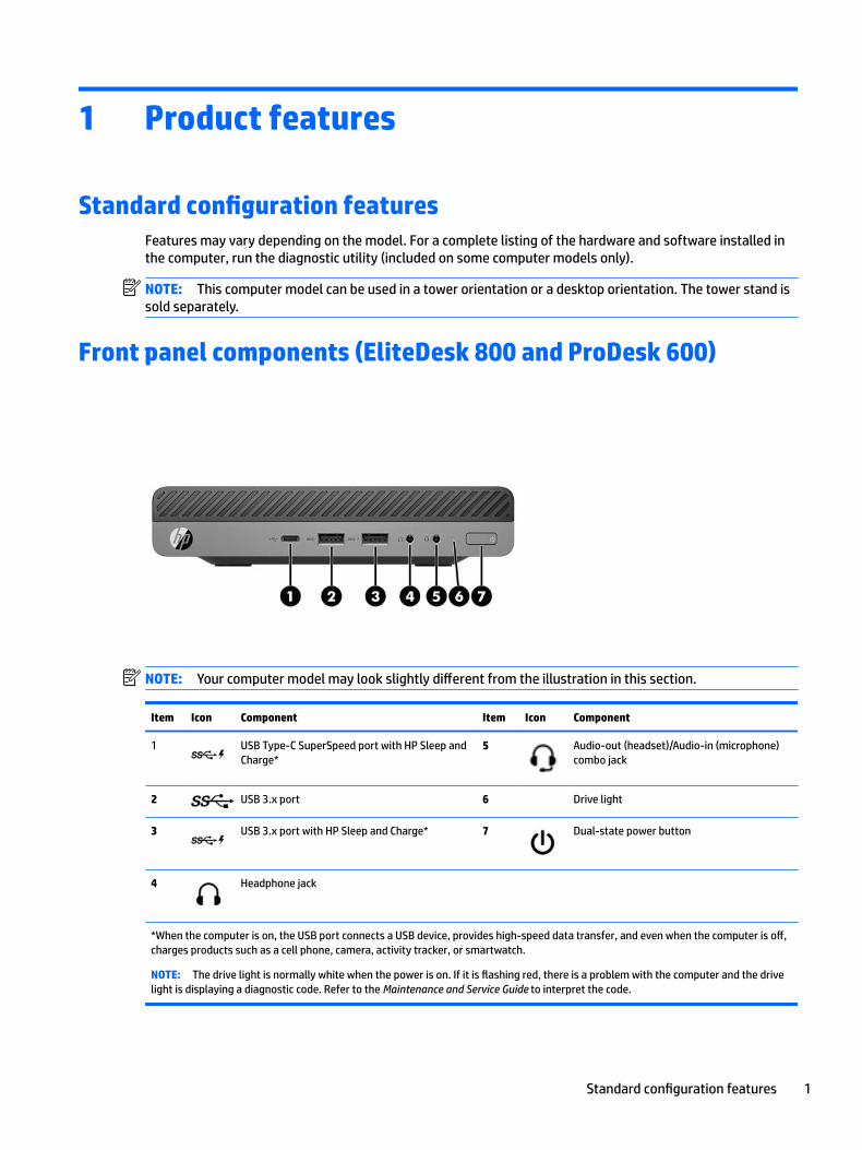
Front panel components (EliteDesk 800 and ProDesk 600)
NOTE: Your computer model may look slightly different from the illustration in this section.
Item Icon Component Item Icon Component
1 USB Type-C SuperSpeed port with HP Sleep and Charge*
5 Audio-out (headset)/Audio-in (microphone) combo jack
2 USB 3.x port 6 Drive light
3 USB 3.x port with HP Sleep and Charge* 7 Dual-state power button
4 Headphone jack
*When the computer is on, the USB port connects a USB device, provides high-speed data transfer, and even when the computer is off, charges products such as a cell phone, camera, activity tracker, or smartwatch.
NOTE: The drive light is normally white when the power is on. If it is flashing red, there is a problem with the computer and the drive light is displaying a diagnostic code. Refer to the Maintenance and Service Guide to interpret the code.
Standard configuration features 1
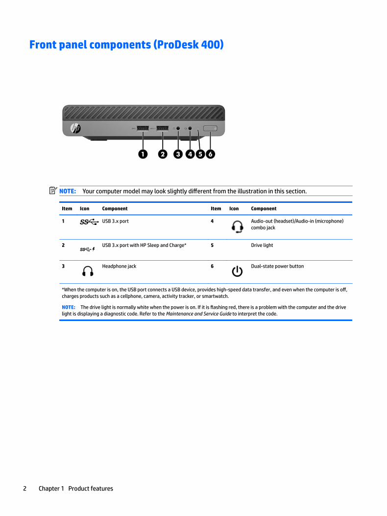
Front panel components (ProDesk 400)
NOTE: Your computer model may look slightly different from the illustration in this section.
Item Icon Component Item Icon Component
1 USB 3.x port 4 Audio-out (headset)/Audio-in (microphone) combo jack
2 USB 3.x port with HP Sleep and Charge* 5 Drive light
3 Headphone jack 6 Dual-state power button
*When the computer is on, the USB port connects a USB device, provides high-speed data transfer, and even when the computer is off, charges products such as a cellphone, camera, activity tracker, or smartwatch.
NOTE: The drive light is normally white when the power is on. If it is flashing red, there is a problem with the computer and the drive light is displaying a diagnostic code. Refer to the Maintenance and Service Guide to interpret the code.
2 Chapter 1 Product features
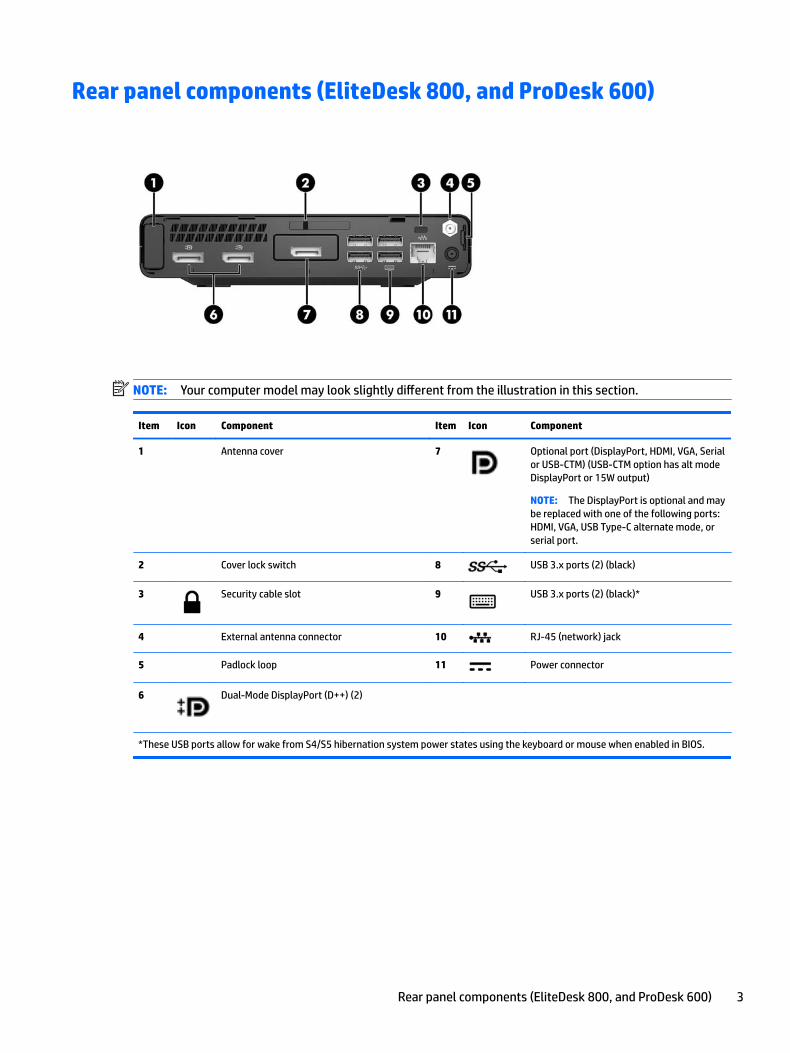
Rear panel components (EliteDesk 800, and ProDesk 600)
NOTE: Your computer model may look slightly different from the illustration in this section.
Item Icon Component Item Icon Component
1 Antenna cover 7 Optional port (DisplayPort, HDMI, VGA, Serial or USB-CTM) (USB-CTM option has alt mode DisplayPort or 15W output)
NOTE: The DisplayPort is optional and may be replaced with one of the following ports: HDMI, VGA, USB Type-C alternate mode, or serial port.
2 Cover lock switch 8 USB 3.x ports (2) (black)
3 Security cable slot 9 USB 3.x ports (2) (black)*
4 External antenna connector 10 RJ-45 (network) jack
5 Padlock loop 11 Power connector
6 Dual-Mode DisplayPort (D++) (2)
*These USB ports allow for wake from S4/S5 hibernation system power states using the keyboard or mouse when enabled in BIOS.
Rear panel components (EliteDesk 800, and ProDesk 600) 3
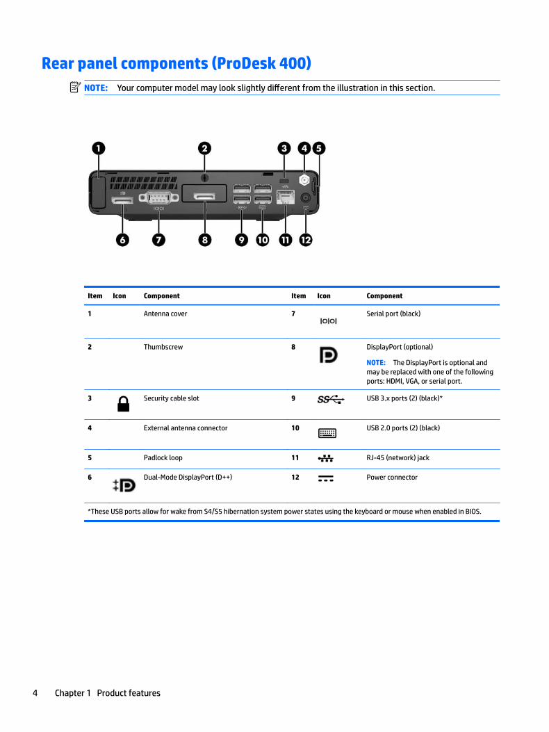
Rear panel components (ProDesk 400)NOTE: Your computer model may look slightly different from the illustration in this section.
Item Icon Component Item Icon Component
1 Antenna cover 7 Serial port (black)
2 Thumbscrew 8 DisplayPort (optional)
NOTE: The DisplayPort is optional and may be replaced with one of the following ports: HDMI, VGA, or serial port.
3 Security cable slot 9 USB 3.x ports (2) (black)*
4 External antenna connector 10 USB 2.0 ports (2) (black)
5 Padlock loop 11 RJ-45 (network) jack
6 Dual-Mode DisplayPort (D++) 12 Power connector
*These USB ports allow for wake from S4/S5 hibernation system power states using the keyboard or mouse when enabled in BIOS.
4 Chapter 1 Product features
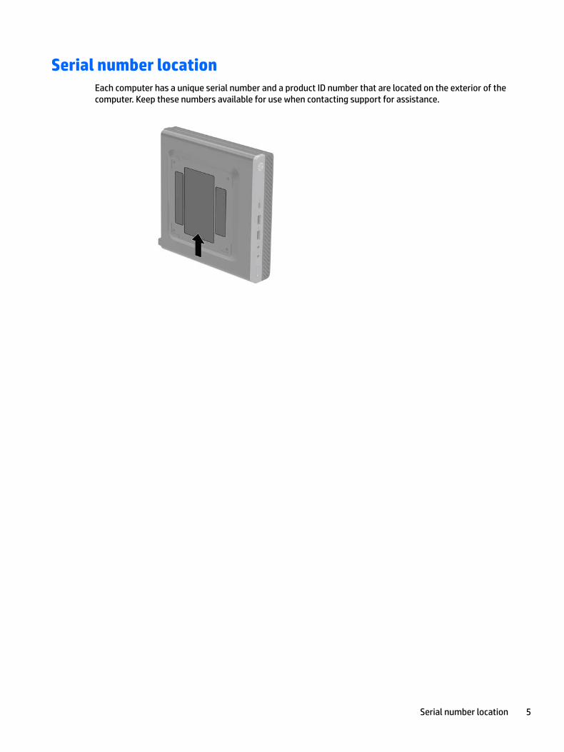
Serial number locationEach computer has a unique serial number and a product ID number that are located on the exterior of the computer. Keep these numbers available for use when contacting support for assistance.
Serial number location 5
2 Illustrated parts catalog
Desktop Mini (DM) chassis spare partsNOTE: HP continually improves and changes product parts. For complete and current information on supported parts for your computer, go to http://partsurfer.hp.com, select your country or region, and then follow the on-screen instructions.
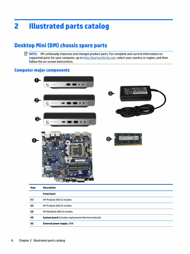
Computer major components
Item Description
Front bezel
(1) HP ProDesk 400 G3 models
(2) HP ProDesk 600 G3 models
(3) HP EliteDesk 800 G3 models
(4) System board (includes replacement thermal material)
(5) External power supply, 90W
6 Chapter 2 Illustrated parts catalog
Item Description
90 W
65 W
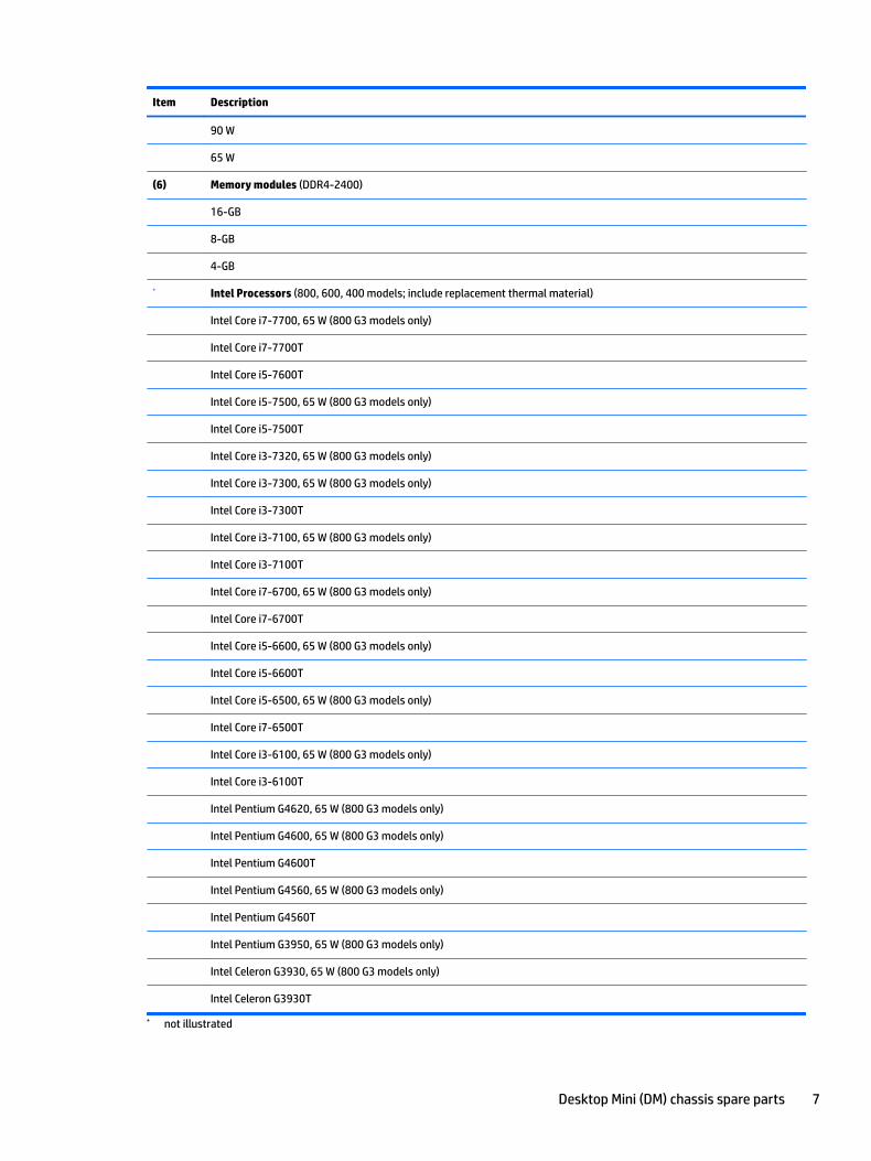
(6) Memory modules (DDR4-2400)
16-GB
8-GB
4-GB
* Intel Processors (800, 600, 400 models; include replacement thermal material)
Intel Core i7-7700, 65 W (800 G3 models only)
Intel Core i7-7700T
Intel Core i5-7600T
Intel Core i5-7500, 65 W (800 G3 models only)
Intel Core i5-7500T
Intel Core i3-7320, 65 W (800 G3 models only)
Intel Core i3-7300, 65 W (800 G3 models only)
Intel Core i3-7300T
Intel Core i3-7100, 65 W (800 G3 models only)
Intel Core i3-7100T
Intel Core i7-6700, 65 W (800 G3 models only)
Intel Core i7-6700T
Intel Core i5-6600, 65 W (800 G3 models only)
Intel Core i5-6600T
Intel Core i5-6500, 65 W (800 G3 models only)
Intel Core i7-6500T
Intel Core i3-6100, 65 W (800 G3 models only)
Intel Core i3-6100T
Intel Pentium G4620, 65 W (800 G3 models only)
Intel Pentium G4600, 65 W (800 G3 models only)
Intel Pentium G4600T
Intel Pentium G4560, 65 W (800 G3 models only)
Intel Pentium G4560T
Intel Pentium G3950, 65 W (800 G3 models only)
Intel Celeron G3930, 65 W (800 G3 models only)
Intel Celeron G3930T
* not illustrated
Desktop Mini (DM) chassis spare parts 7
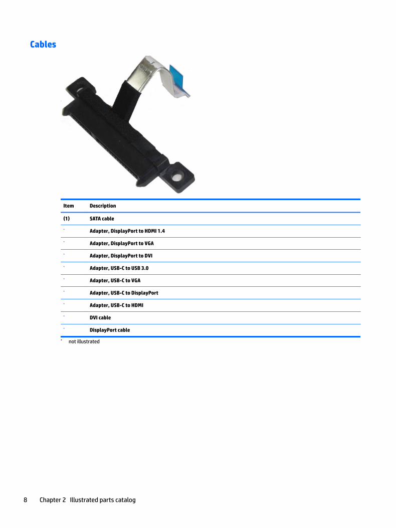
Cables
Item Description
(1) SATA cable
* Adapter, DisplayPort to HDMI 1.4
* Adapter, DisplayPort to VGA
* Adapter, DisplayPort to DVI
* Adapter, USB-C to USB 3.0
* Adapter, USB-C to VGA
* Adapter, USB-C to DisplayPort
* Adapter, USB-C to HDMI
* DVI cable
* DisplayPort cable
* not illustrated
8 Chapter 2 Illustrated parts catalog
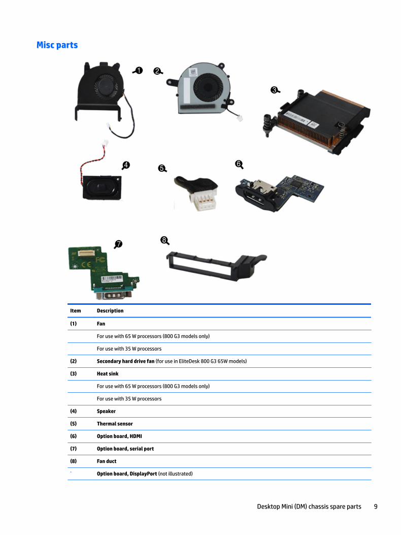
Misc parts
Item Description
(1) Fan
For use with 65 W processors (800 G3 models only)
For use with 35 W processors
(2) Secondary hard drive fan (for use in EliteDesk 800 G3 65W models)
(3) Heat sink
For use with 65 W processors (800 G3 models only)
For use with 35 W processors
(4) Speaker
(5) Thermal sensor
(6) Option board, HDMI
(7) Option board, serial port
(8) Fan duct
* Option board, DisplayPort (not illustrated)
Desktop Mini (DM) chassis spare parts 9
Item Description
* Option board, USB Type-C (not illustrated)
* Option board, VGA (not illustrated)
* Screw kit
* Stand
* Port cover
* Dust filter
* EPS bracket
* HP Dual Head Keyed Cable Lock
* HP Dual Head Keyed Cable Lock
* Grommet, hard drive
* WLAN modules:
Intel 8265 802.11AC 2x2 Wi-Fi +Bluetooth M.2 Combo Card non-VPro
Intel 7265 802.11AC 2x2 Wi-Fi +Bluetooth M.2 Combo Card non-VPro
Intel 3168 802.11AC 2x2 Wi-Fi +Bluetooth M.2 Combo Card non-VPro
* Internal antenna kit
* External antenna kit
* Antenna cover, internal
* WLAN wiring kit
* Expansion Sleeve Kit
Hard drive – I/O
I/O
Optical drive
USB 3.0 Type A-B
USB 3.0 Type A-B (short)
* Dual VESA Sleeve
* Mouse
USB, laser
USB, optical
USB, grey
Wireless
Antimicrobial
Hardened
* Keyboards
USB slim
10 Chapter 2 Illustrated parts catalog
Item Description
USB slim, grey
Wireless keyboard, mouse, and receiver
Washable
USB Smart card
Conferencing
Antimicrobial
* not illustrated
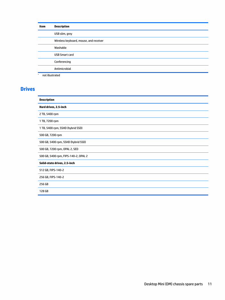
Drives
Description
Hard drives, 2.5-inch
2 TB, 5400 rpm
1 TB, 7200 rpm
1 TB, 5400 rpm, SSHD (hybrid SSD)
500 GB, 7200 rpm
500 GB, 5400 rpm, SSHD (hybrid SSD)
500 GB, 7200 rpm, OPAL 2, SED
500 GB, 5400 rpm, FIPS-140-2, OPAL 2
Solid-state drives, 2.5-inch
512 GB, FIPS-140-2
256 GB, FIPS-140-2
256 GB
128 GB
Desktop Mini (DM) chassis spare parts 11
3 Routine care, SATA drive guidelines, and disassembly preparation
This chapter provides general service information for the computer. Adherence to the procedures and precautions described in this chapter is essential for proper service.
CAUTION: When the computer is plugged into an AC power source, voltage is always applied to the system board. You must disconnect the power cord from the power source before opening the computer to prevent system board or component damage.
Electrostatic discharge informationA sudden discharge of static electricity from your finger or other conductor can destroy static-sensitive devices or microcircuitry. Often the spark is neither felt nor heard, but damage occurs. An electronic device exposed to electrostatic discharge (ESD) may not appear to be affected at all and can work perfectly throughout a normal cycle. The device may function normally for a while, but it has been degraded in the internal layers, reducing its life expectancy.
Networks built into many integrated circuits provide some protection, but in many cases, the discharge contains enough power to alter device parameters or melt silicon junctions.
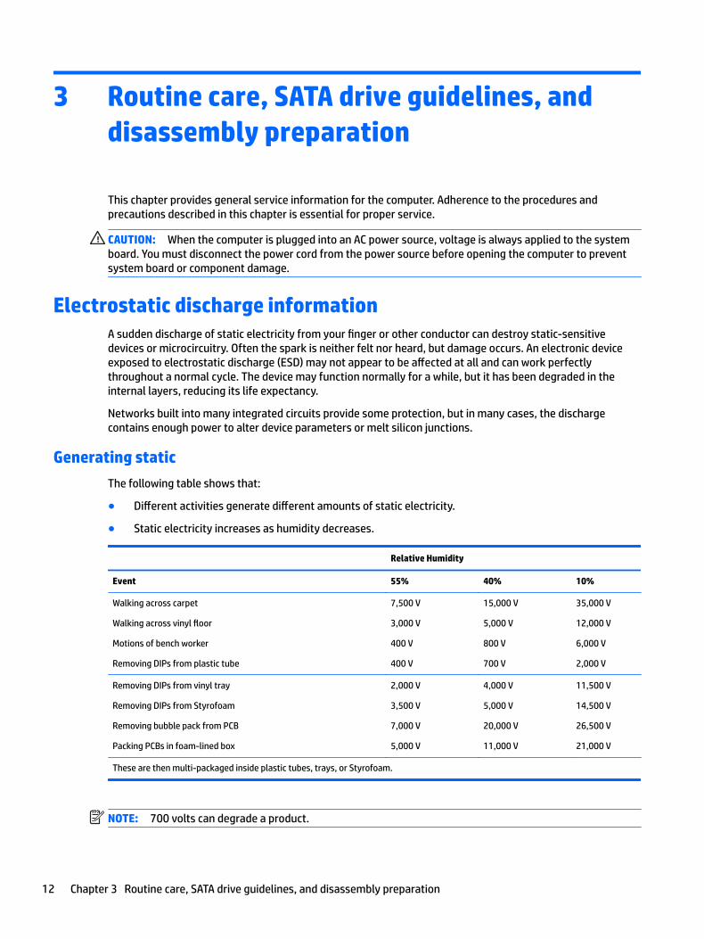
Generating static
The following table shows that:
● Different activities generate different amounts of static electricity.
● Static electricity increases as humidity decreases.
Relative Humidity
Event 55% 40% 10%
Walking across carpet
Walking across vinyl floor
Motions of bench worker
Removing DIPs from plastic tube
7,500 V
3,000 V
400 V
400 V
15,000 V
5,000 V
800 V
700 V
35,000 V
12,000 V
6,000 V
2,000 V
Removing DIPs from vinyl tray
Removing DIPs from Styrofoam
Removing bubble pack from PCB
Packing PCBs in foam-lined box
2,000 V
3,500 V
7,000 V
5,000 V
4,000 V
5,000 V
20,000 V
11,000 V
11,500 V
14,500 V
26,500 V
21,000 V
These are then multi-packaged inside plastic tubes, trays, or Styrofoam.
NOTE: 700 volts can degrade a product.
12 Chapter 3 Routine care, SATA drive guidelines, and disassembly preparation
Preventing electrostatic damage to equipment
Many electronic components are sensitive to ESD. Circuitry design and structure determine the degree of sensitivity. The following packaging and grounding precautions are necessary to prevent damage to electric components and accessories.
● To avoid hand contact, transport products in static-safe containers such as tubes, bags, or boxes.
● Protect all electrostatic parts and assemblies with conductive or approved containers or packaging.
● Keep electrostatic sensitive parts in their containers until they arrive at static-free stations.
● Place items on a grounded surface before removing them from their container.
● Always be properly grounded when touching a sensitive component or assembly.
● Avoid contact with pins, leads, or circuitry.
● Place reusable electrostatic-sensitive parts from assemblies in protective packaging or conductive foam.
Personal grounding methods and equipment
Use the following equipment to prevent static electricity damage to equipment:
● Wrist straps are flexible straps with a maximum of one-megohm ± 10% resistance in the ground cords. To provide proper ground, a strap must be worn snug against bare skin. The ground cord must be connected and fit snugly into the banana plug connector on the grounding mat or workstation.
● Heel straps/Toe straps/Boot straps can be used at standing workstations and are compatible with most types of shoes or boots. On conductive floors or dissipative floor mats, use them on both feet with a maximum of one-megohm ± 10% resistance between the operator and ground.
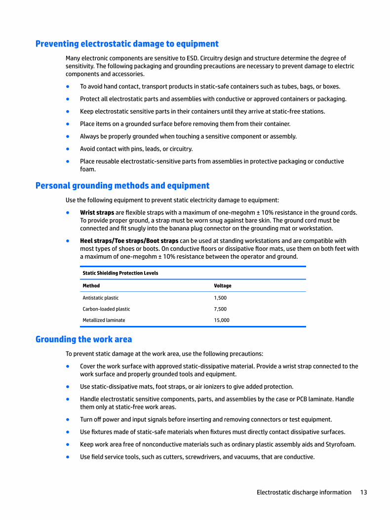
Static Shielding Protection Levels
Method Voltage
Antistatic plastic
Carbon-loaded plastic
Metallized laminate
1,500
7,500
15,000
Grounding the work area
To prevent static damage at the work area, use the following precautions:
● Cover the work surface with approved static-dissipative material. Provide a wrist strap connected to the work surface and properly grounded tools and equipment.
● Use static-dissipative mats, foot straps, or air ionizers to give added protection.
● Handle electrostatic sensitive components, parts, and assemblies by the case or PCB laminate. Handle them only at static-free work areas.
● Turn off power and input signals before inserting and removing connectors or test equipment.
● Use fixtures made of static-safe materials when fixtures must directly contact dissipative surfaces.
● Keep work area free of nonconductive materials such as ordinary plastic assembly aids and Styrofoam.
● Use field service tools, such as cutters, screwdrivers, and vacuums, that are conductive.
Electrostatic discharge information 13
Recommended materials and equipment
Materials and equipment that are recommended for use in preventing static electricity include:
● Antistatic tape
● Antistatic smocks, aprons, or sleeve protectors
● Conductive bins and other assembly or soldering aids
● Conductive foam
● Conductive tabletop workstations with ground cord of one-megohm +/- 10% resistance
● Static-dissipative table or floor mats with hard tie to ground
● Field service kits
● Static awareness labels
● Wrist straps and footwear straps providing one-megohm +/- 10% resistance
● Material handling packages
● Conductive plastic bags
● Conductive plastic tubes
● Conductive tote boxes
● Opaque shielding bags
● Transparent metallized shielding bags
● Transparent shielding tubes
Operating guidelinesTo prevent overheating and to help prolong the life of the computer:
● Keep the computer away from excessive moisture, direct sunlight, and extremes of heat and cold.
● Operate the computer on a sturdy, level surface. Leave a 10.2-cm (4-inch) clearance on all vented sides of the computer and above the monitor to permit the required airflow.
● Never restrict the airflow into the computer by blocking any vents or air intakes. Do not place the keyboard, with the keyboard feet down, directly against the front of the desktop unit as this also restricts airflow.
● Occasionally clean the air vents on all vented sides of the computer. Lint, dust, and other foreign matter can block the vents and limit the airflow. Be sure to unplug the computer before cleaning the air vents.
● Never operate the computer with the cover or side panel removed.
● Do not stack computers on top of each other or place computers so near each other that they are subject to each other’s re-circulated or preheated air.
● If the computer is to be operated within a separate enclosure, intake and exhaust ventilation must be provided on the enclosure, and the same operating guidelines listed above will still apply.
● Keep liquids away from the computer and keyboard.
14 Chapter 3 Routine care, SATA drive guidelines, and disassembly preparation
● Never cover the ventilation slots on the monitor with any type of material.
● Install or enable power management functions of the operating system or other software, including sleep states.
Routine care
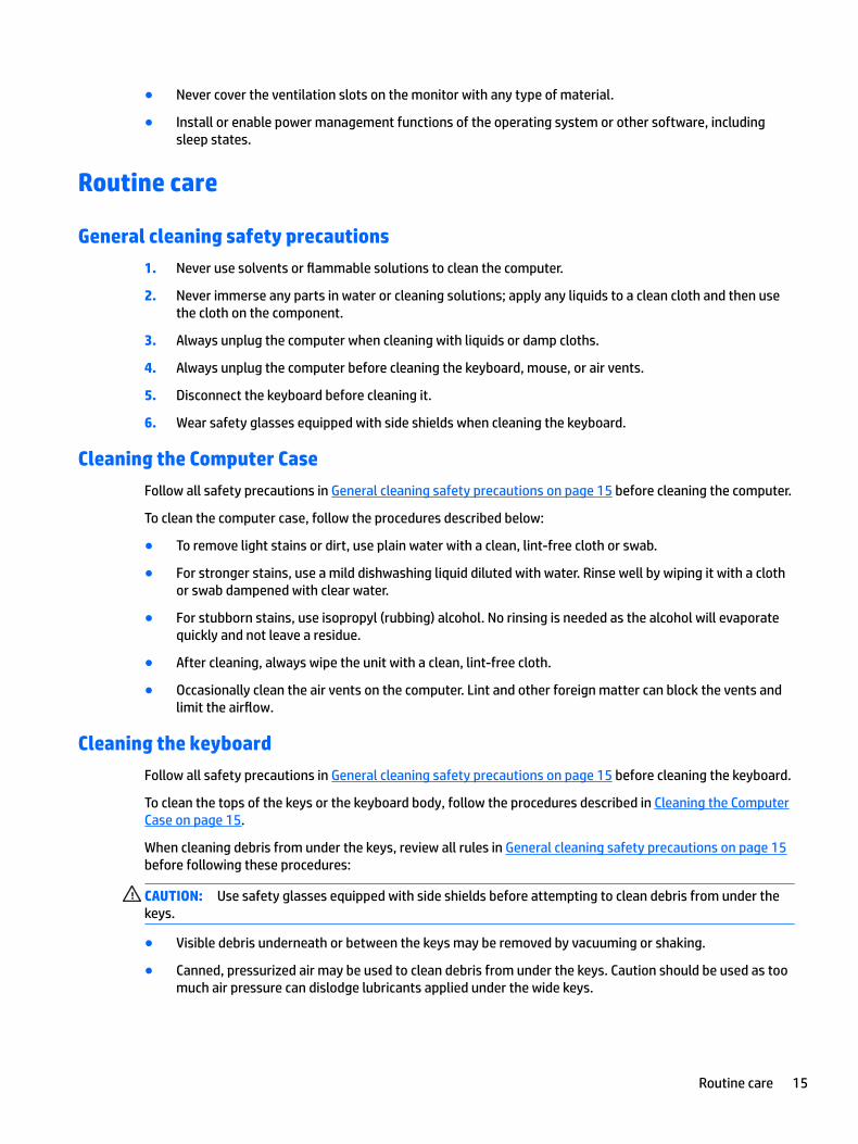
General cleaning safety precautions
1. Never use solvents or flammable solutions to clean the computer.
2. Never immerse any parts in water or cleaning solutions; apply any liquids to a clean cloth and then use the cloth on the component.
3. Always unplug the computer when cleaning with liquids or damp cloths.
4. Always unplug the computer before cleaning the keyboard, mouse, or air vents.
5. Disconnect the keyboard before cleaning it.
6. Wear safety glasses equipped with side shields when cleaning the keyboard.
Cleaning the Computer Case
Follow all safety precautions in General cleaning safety precautions on page 15 before cleaning the computer.
To clean the computer case, follow the procedures described below:
● To remove light stains or dirt, use plain water with a clean, lint-free cloth or swab.
● For stronger stains, use a mild dishwashing liquid diluted with water. Rinse well by wiping it with a cloth or swab dampened with clear water.
● For stubborn stains, use isopropyl (rubbing) alcohol. No rinsing is needed as the alcohol will evaporate quickly and not leave a residue.
● After cleaning, always wipe the unit with a clean, lint-free cloth.
● Occasionally clean the air vents on the computer. Lint and other foreign matter can block the vents and limit the airflow.
Cleaning the keyboard
Follow all safety precautions in General cleaning safety precautions on page 15 before cleaning the keyboard.
To clean the tops of the keys or the keyboard body, follow the procedures described in Cleaning the Computer Case on page 15.
When cleaning debris from under the keys, review all rules in General cleaning safety precautions on page 15 before following these procedures:
CAUTION: Use safety glasses equipped with side shields before attempting to clean debris from under the keys.
● Visible debris underneath or between the keys may be removed by vacuuming or shaking.
● Canned, pressurized air may be used to clean debris from under the keys. Caution should be used as too much air pressure can dislodge lubricants applied under the wide keys.
Routine care 15
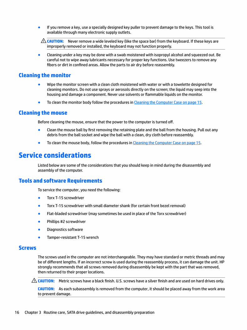
● If you remove a key, use a specially designed key puller to prevent damage to the keys. This tool is available through many electronic supply outlets.
CAUTION: Never remove a wide leveled key (like the space bar) from the keyboard. If these keys are improperly removed or installed, the keyboard may not function properly.
● Cleaning under a key may be done with a swab moistened with isopropyl alcohol and squeezed out. Be careful not to wipe away lubricants necessary for proper key functions. Use tweezers to remove any fibers or dirt in confined areas. Allow the parts to air dry before reassembly.
Cleaning the monitor
● Wipe the monitor screen with a clean cloth moistened with water or with a towelette designed for cleaning monitors. Do not use sprays or aerosols directly on the screen; the liquid may seep into the housing and damage a component. Never use solvents or flammable liquids on the monitor.
● To clean the monitor body follow the procedures in Cleaning the Computer Case on page 15.
Cleaning the mouse
Before cleaning the mouse, ensure that the power to the computer is turned off.
● Clean the mouse ball by first removing the retaining plate and the ball from the housing. Pull out any debris from the ball socket and wipe the ball with a clean, dry cloth before reassembly.
● To clean the mouse body, follow the procedures in Cleaning the Computer Case on page 15.
Service considerationsListed below are some of the considerations that you should keep in mind during the disassembly and assembly of the computer.
Tools and software Requirements
To service the computer, you need the following:
● Torx T-15 screwdriver
● Torx T-15 screwdriver with small diameter shank (for certain front bezel removal)
● Flat-bladed screwdriver (may sometimes be used in place of the Torx screwdriver)
● Phillips #2 screwdriver
● Diagnostics software
● Tamper-resistant T-15 wrench
Screws
The screws used in the computer are not interchangeable. They may have standard or metric threads and may be of different lengths. If an incorrect screw is used during the reassembly process, it can damage the unit. HP strongly recommends that all screws removed during disassembly be kept with the part that was removed, then returned to their proper locations.
CAUTION: Metric screws have a black finish. U.S. screws have a silver finish and are used on hard drives only.
CAUTION: As each subassembly is removed from the computer, it should be placed away from the work area to prevent damage.
16 Chapter 3 Routine care, SATA drive guidelines, and disassembly preparation
Cables and connectors
Most cables used throughout the unit are flat, flexible cables. These cables must be handled with care to avoid damage. Apply only the tension required to seat or unseat the cables during insertion or removal from the connector. Handle cables by the connector whenever possible. In all cases, avoid bending or twisting the cables, and ensure that the cables are routed in such a way that they cannot be caught or snagged by parts being removed or replaced.
CAUTION: When servicing this computer, ensure that cables are placed in their proper location during the reassembly process. Improper cable placement can damage the computer.
Hard Drives
Handle hard drives as delicate, precision components, avoiding all physical shock and vibration. This applies to failed drives as well as replacement spares.
● If a drive must be mailed, place the drive in a bubble-pack mailer or other suitable protective packaging and label the package “Fragile: Handle With Care.”
● Do not remove hard drives from the shipping package for storage. Keep hard drives in their protective packaging until they are actually mounted in the computer.
● Avoid dropping drives from any height onto any surface.
● If you are inserting or removing a hard drive, turn off the computer. Do not remove a hard drive while the computer is on or in standby mode.
● Before handling a drive, ensure that you are discharged of static electricity. While handling a drive, avoid touching the connector.
● Do not use excessive force when inserting a drive.
● Avoid exposing a hard drive to liquids, temperature extremes, or products that have magnetic fields such as monitors or speakers.
Lithium coin cell battery
The battery that comes with the computer provides power to the real-time clock and has a minimum lifetime of about three years.
See the appropriate removal and replacement chapter for the chassis you are working on in this guide for instructions on the replacement procedures.
WARNING! This computer contains a lithium battery. There is a risk of fire and chemical burn if the battery is handled improperly. Do not disassemble, crush, puncture, short external contacts, dispose in water or fire, or expose it to temperatures higher than 140ºF (60ºC). Do not attempt to recharge the battery.
NOTE: Batteries, battery packs, and accumulators should not be disposed of together with the general household waste. In order to forward them to recycling or proper disposal, please use the public collection system or return them to HP, their authorized partners, or their agents.
Service considerations 17
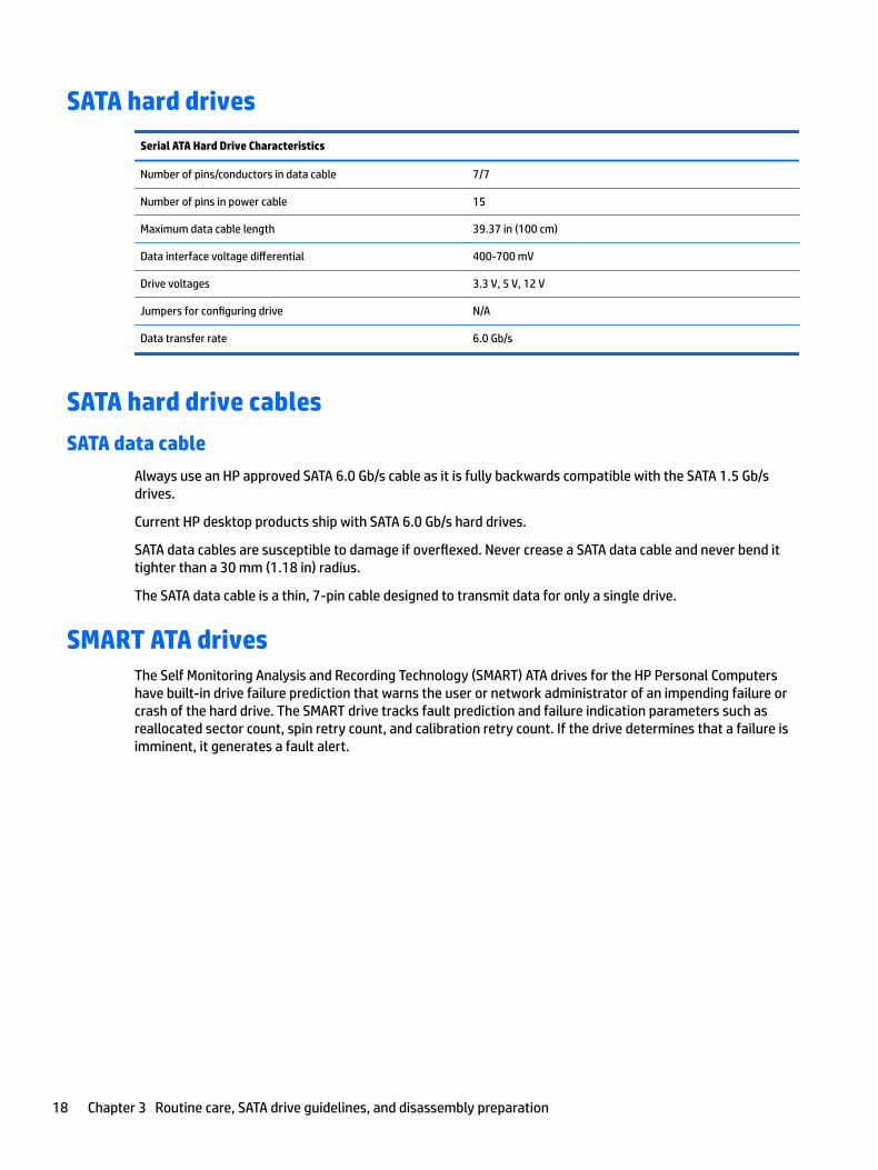
SATA hard drives
Serial ATA Hard Drive Characteristics
Number of pins/conductors in data cable 7/7
Number of pins in power cable 15
Maximum data cable length 39.37 in (100 cm)
Data interface voltage differential 400-700 mV
Drive voltages 3.3 V, 5 V, 12 V
Jumpers for configuring drive N/A
Data transfer rate 6.0 Gb/s
SATA hard drive cables
SATA data cable
Always use an HP approved SATA 6.0 Gb/s cable as it is fully backwards compatible with the SATA 1.5 Gb/s drives.
Current HP desktop products ship with SATA 6.0 Gb/s hard drives.
SATA data cables are susceptible to damage if overflexed. Never crease a SATA data cable and never bend it tighter than a 30 mm (1.18 in) radius.
The SATA data cable is a thin, 7-pin cable designed to transmit data for only a single drive.
SMART ATA drivesThe Self Monitoring Analysis and Recording Technology (SMART) ATA drives for the HP Personal Computers have built-in drive failure prediction that warns the user or network administrator of an impending failure or crash of the hard drive. The SMART drive tracks fault prediction and failure indication parameters such as reallocated sector count, spin retry count, and calibration retry count. If the drive determines that a failure is imminent, it generates a fault alert.
18 Chapter 3 Routine care, SATA drive guidelines, and disassembly preparation

Cable managementAlways follow good cable management practices when working inside the computer.
● Keep cables away from major heat sources like the heat sink.
● Do not jam cables on top of expansion cards or memory modules. Printed circuit cards like these are not designed to take excessive pressure on them.
● Keep cables clear of sliding or moveable parts to prevent them from being cut or crimped when the parts are moved.
● When folding a flat ribbon cable, never fold to a sharp crease. Sharp creases may damage the wires.
● Some flat ribbon cables come prefolded. Never change the folds on these cables.
● Do not bend any cable sharply. A sharp bend can break the internal wires.
● Never bend a SATA data cable tighter than a 30 mm (1.18 in) radius.
● Never crease a SATA data cable.
● Do not rely on components like the drive cage, power supply, or computer cover to push cables down into the chassis. Always position the cables to lay properly by themselves.
Cable management 19
4 Removal and replacement procedures – desktop mini (DM) chassis
Adherence to the procedures and precautions described in this chapter is essential for proper service. After completing all necessary removal and replacement procedures, run the Diagnostics utility to verify that all components operate properly.
NOTE: Not all features listed in this guide are available on all computers.
NOTE: HP continually improves and changes product parts. For complete and current information on supported parts for your computer, go to http://partsurfer.hp.com, select your country or region, and then follow the on-screen instructions.
Preparation for disassemblySee Routine care, SATA drive guidelines, and disassembly preparation on page 12 for initial safety procedures.
1. Remove/disengage any security devices that prohibit opening the computer.
2. Remove all removable media, such as a USB flash drive, from the computer.
3. Turn off the computer properly through the operating system, then turn off any external devices.
CAUTION: Turn off the computer before disconnecting any cables.
Regardless of the power-on state, voltage is always present on the system board as long as the system is plugged into an active AC outlet. In some systems the cooling fan is on even when the computer is in the “Standby,” or “Suspend” modes. The power cord should always be disconnected before servicing a unit.
4. Disconnect the power cord from the power outlet and disconnect any external devices.
5. If the computer is on a stand, remove the computer from the stand.
WARNING! Beware of sharp edges inside the chassis.
20 Chapter 4 Removal and replacement procedures – desktop mini (DM) chassis
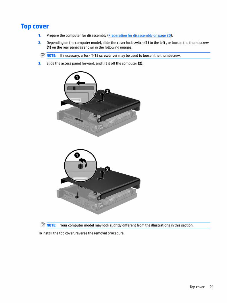
Top cover1. Prepare the computer for disassembly (Preparation for disassembly on page 20).
2. Depending on the computer model, slide the cover lock switch (1) to the left , or loosen the thumbscrew (1) on the rear panel as shown in the following images.
NOTE: If necessary, a Torx T-15 screwdriver may be used to loosen the thumbscrew.
3. Slide the access panel forward, and lift it off the computer (2).
NOTE: Your computer model may look slightly different from the illustrations in this section.
To install the top cover, reverse the removal procedure.
Top cover 21
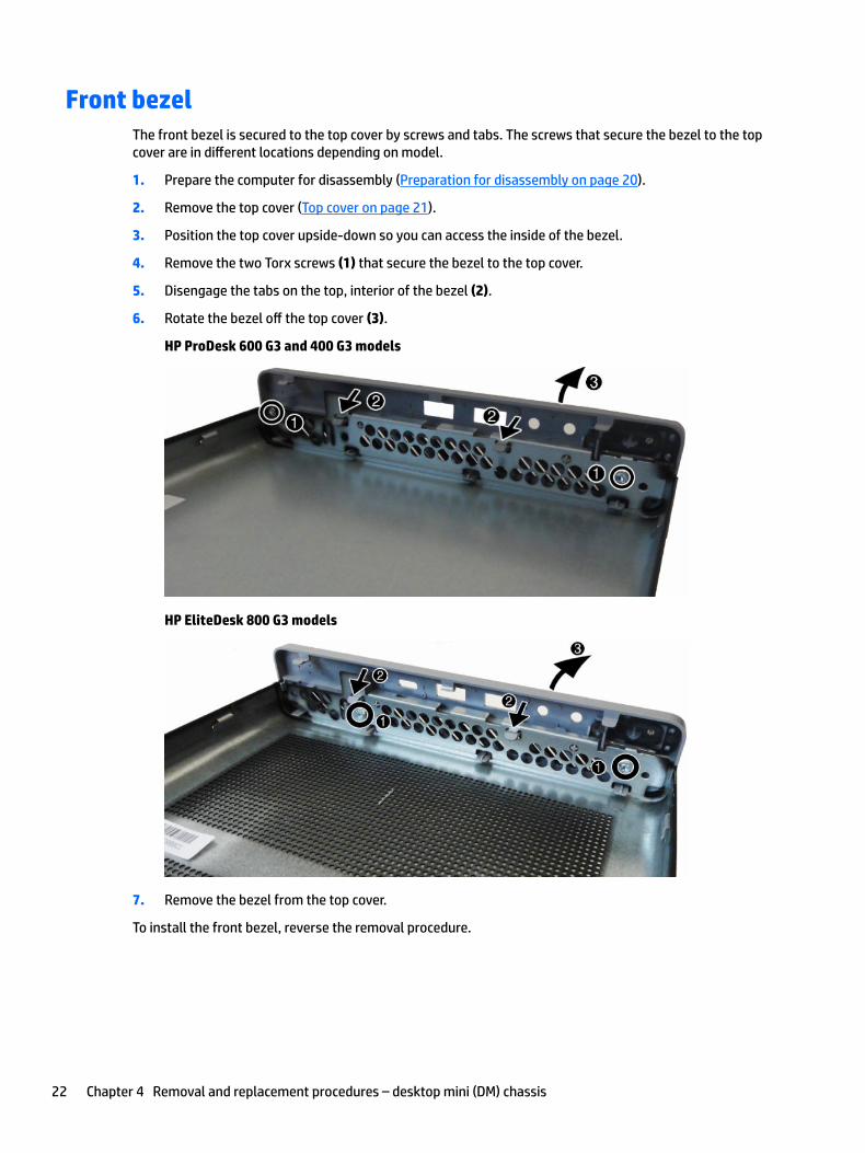
Front bezelThe front bezel is secured to the top cover by screws and tabs. The screws that secure the bezel to the top cover are in different locations depending on model.
1. Prepare the computer for disassembly (Preparation for disassembly on page 20).
2. Remove the top cover (Top cover on page 21).
3. Position the top cover upside-down so you can access the inside of the bezel.
4. Remove the two Torx screws (1) that secure the bezel to the top cover.
5. Disengage the tabs on the top, interior of the bezel (2).
6. Rotate the bezel off the top cover (3).
HP ProDesk 600 G3 and 400 G3 models
HP EliteDesk 800 G3 models
7. Remove the bezel from the top cover.
To install the front bezel, reverse the removal procedure.
22 Chapter 4 Removal and replacement procedures – desktop mini (DM) chassis
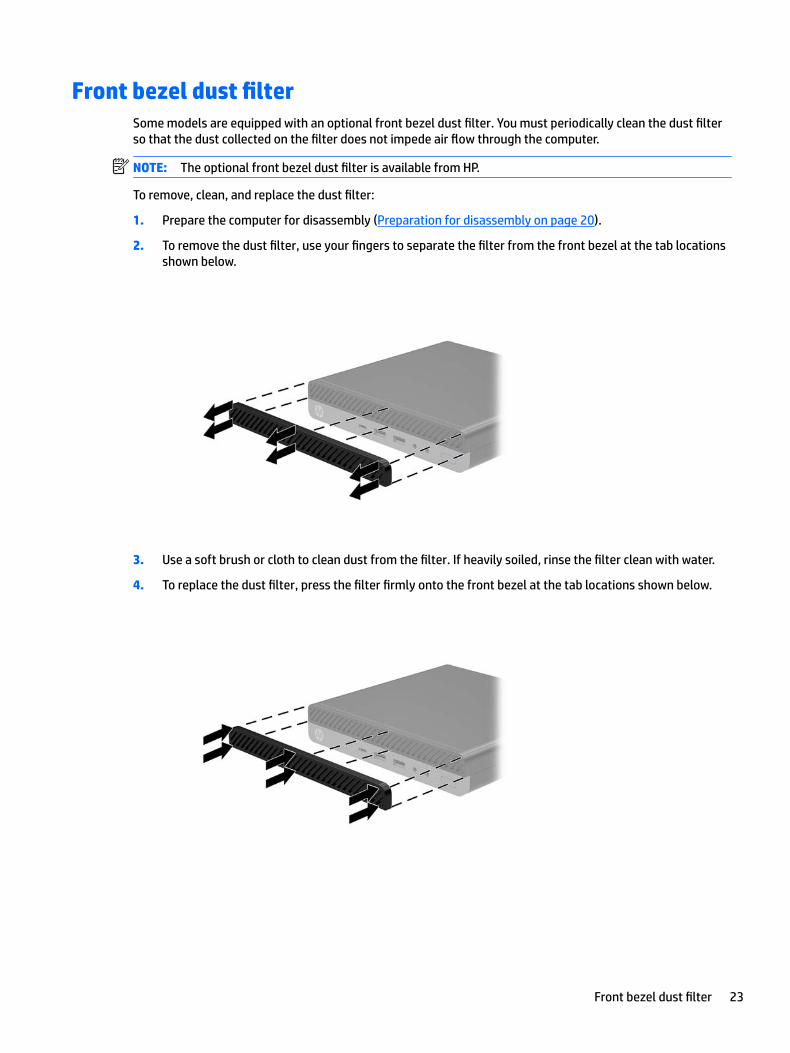
Front bezel dust filterSome models are equipped with an optional front bezel dust filter. You must periodically clean the dust filter so that the dust collected on the filter does not impede air flow through the computer.
NOTE: The optional front bezel dust filter is available from HP.
To remove, clean, and replace the dust filter:
1. Prepare the computer for disassembly (Preparation for disassembly on page 20).
2. To remove the dust filter, use your fingers to separate the filter from the front bezel at the tab locations shown below.
3. Use a soft brush or cloth to clean dust from the filter. If heavily soiled, rinse the filter clean with water.
4. To replace the dust filter, press the filter firmly onto the front bezel at the tab locations shown below.
Front bezel dust filter 23
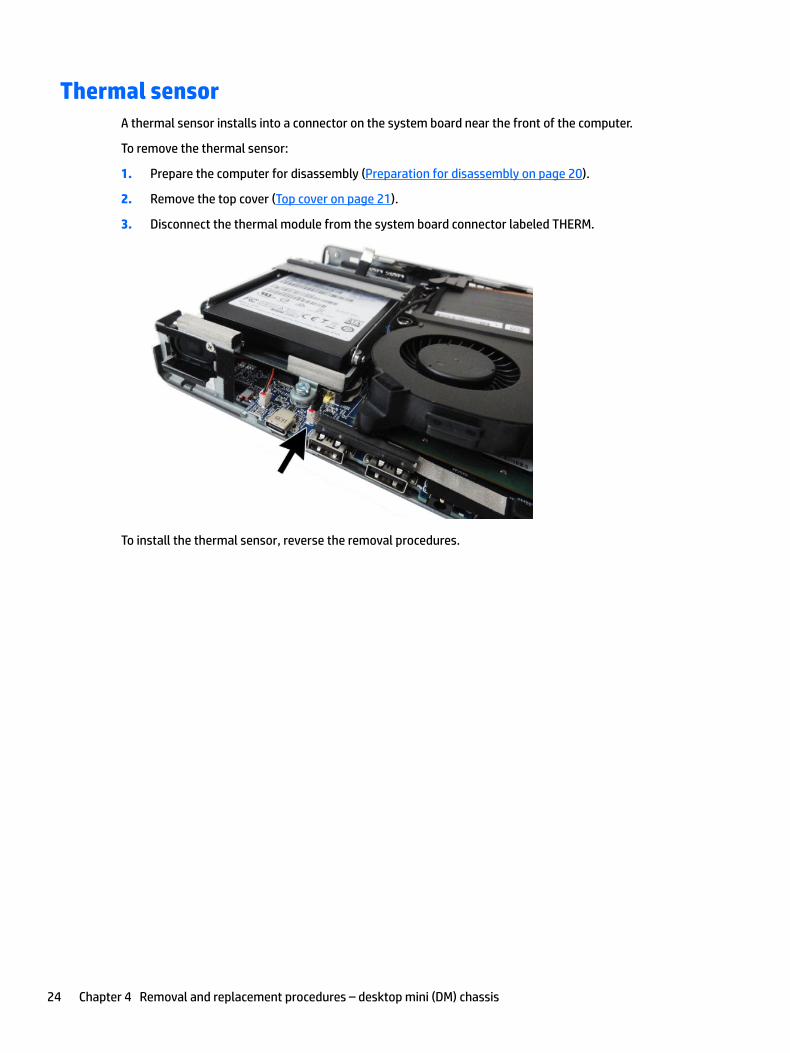
Thermal sensorA thermal sensor installs into a connector on the system board near the front of the computer.
To remove the thermal sensor:
1. Prepare the computer for disassembly (Preparation for disassembly on page 20).
2. Remove the top cover (Top cover on page 21).
3. Disconnect the thermal module from the system board connector labeled THERM.
To install the thermal sensor, reverse the removal procedures.
24 Chapter 4 Removal and replacement procedures – desktop mini (DM) chassis
Memory
Description
Memory module, 16-GB (PC4-2400)
Memory module, 8-GB (PC4-2400)
Memory module, 4-GB (PC4-2400)
The computer comes with small outline, dual inline memory modules (SODIMMs).
SODIMMs
The computer comes with at least one small outline, dual in-line memory module (SODIMM). To achieve maximum memory support, you can populate the system board with up to 32 GB of memory.
SODIMM specifications
For proper system operation, the memory modules must adhere to the following specifications.
Component Specification
Memory modules 1.2 volt DDR4-SDRAM memory modules
Compliance Unbuffered non-ECC PC4-17000 DDR4-2133 MHz-compliant
Pins Industry-standard 260-pin containing the mandatory Joint Electronic Device Engineering Council (JEDEC) specification
Support CAS latency 15 DDR4 2400 MHz (15-15-15 timing)
Slots 2
Maximum Memory 32 GB
Supported 2 Gbit, 4 Gbit, 8 Gbit, and 16 Gbit non-ECC memory technologies single-sided and double-sided memory modules
NOTE: The system does not operate properly if you install unsupported memory modules. Memory modules constructed with x8 and x16 DDR devices are supported; memory modules constructed with x4 SDRAM are not supported.
HP offers upgrade memory for this computer and advises that the consumer purchase it to avoid compatibility issues with unsupported third-party memory.
Memory 25
Populating SODIMM sockets
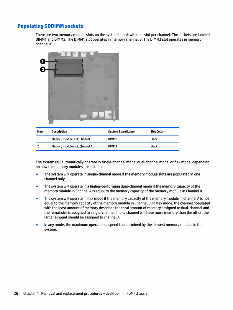
There are two memory module slots on the system board, with one slot per channel. The sockets are labeled DIMM1 and DIMM3. The DIMM1 slot operates in memory channel B. The DIMM3 slot operates in memory channel A.
Item Description System Board Label Slot Color
1 Memory module slot, Channel B DIMM1 Black
2 Memory module slot, Channel A DIMM3 Black
The system will automatically operate in single-channel mode, dual-channel mode, or flex mode, depending on how the memory modules are installed.
● The system will operate in single-channel mode if the memory module slots are populated in one channel only.
● The system will operate in a higher-performing dual-channel mode if the memory capacity of the memory module in Channel A is equal to the memory capacity of the memory module in Channel B.
● The system will operate in flex mode if the memory capacity of the memory module in Channel A is not equal to the memory capacity of the memory module in Channel B. In flex mode, the channel populated with the least amount of memory describes the total amount of memory assigned to dual-channel and the remainder is assigned to single-channel. If one channel will have more memory than the other, the larger amount should be assigned to channel A.
● In any mode, the maximum operational speed is determined by the slowest memory module in the system.
26 Chapter 4 Removal and replacement procedures – desktop mini (DM) chassis
Replacing SODIMMs
CAUTION: You must disconnect the power cord and wait approximately 30 seconds for the power to drain before adding or removing memory modules. Regardless of the power-on state, voltage is always supplied to the memory modules as long as the computer is plugged into an active AC outlet. Adding or removing memory modules while voltage is present may cause irreparable damage to the memory modules or system board.
The memory module sockets have gold-plated metal contacts. When upgrading the memory, it is important to use memory modules with gold-plated metal contacts to prevent corrosion and/or oxidation resulting from having incompatible metals in contact with each other.
Static electricity can damage the electronic components of the computer or optional cards. Before beginning these procedures, ensure that you are discharged of static electricity by briefly touching a grounded metal object.
When handling a memory module, be careful not to touch any of the contacts. Doing so may damage the module.
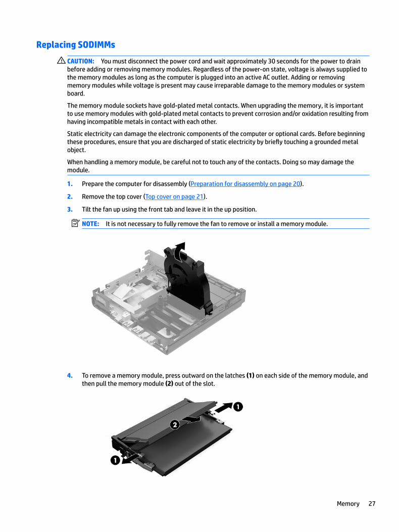
1. Prepare the computer for disassembly (Preparation for disassembly on page 20).
2. Remove the top cover (Top cover on page 21).
3. Tilt the fan up using the front tab and leave it in the up position.
NOTE: It is not necessary to fully remove the fan to remove or install a memory module.
4. To remove a memory module, press outward on the latches (1) on each side of the memory module, and then pull the memory module (2) out of the slot.
Memory 27
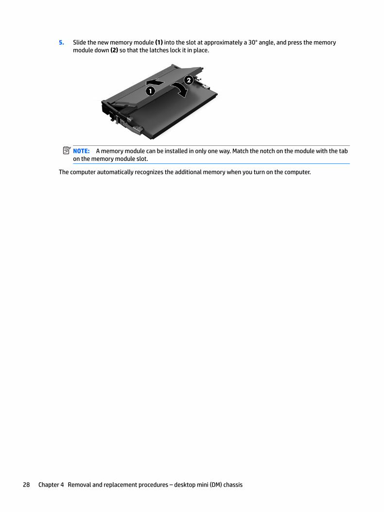
5. Slide the new memory module (1) into the slot at approximately a 30° angle, and press the memory module down (2) so that the latches lock it in place.
NOTE: A memory module can be installed in only one way. Match the notch on the module with the tab on the memory module slot.
The computer automatically recognizes the additional memory when you turn on the computer.
28 Chapter 4 Removal and replacement procedures – desktop mini (DM) chassis

Hard drive
Description
Hard drives, 2.5-inch
2 TB, 5400 rpm
1 TB, 7200 rpm
1 TB, 5400 rpm, SSHD (hybrid SSD)
500 GB, 7200 rpm
500 GB, 5400 rpm, SSHD (hybrid SSD)
500 GB, 7200 rpm, OPAL 2, SED
500 GB, 5400 rpm, FIPS-140-2, OPAL 2
Solid-state drives, 2.5-inch
512 GB, FIPS-140-2
256 GB, FIPS-140-2
256 GB
128 GB
NOTE: Before you remove the old hard drive, be sure to back up the data from the old hard drive so that you can transfer the data to the new hard drive.
1. Prepare the computer for disassembly (Preparation for disassembly on page 20).
2. Remove the top cover Top cover on page 21.
3. To remove the hard drive, rotate the hard drive latch up and out (1) to disengage the hard drive from the cage.
Hard drive 29
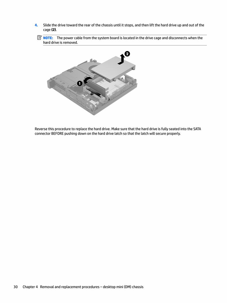
4. Slide the drive toward the rear of the chassis until it stops, and then lift the hard drive up and out of the cage (2).
NOTE: The power cable from the system board is located in the drive cage and disconnects when the hard drive is removed.
Reverse this procedure to replace the hard drive. Make sure that the hard drive is fully seated into the SATA connector BEFORE pushing down on the hard drive latch so that the latch will secure properly.
30 Chapter 4 Removal and replacement procedures – desktop mini (DM) chassis
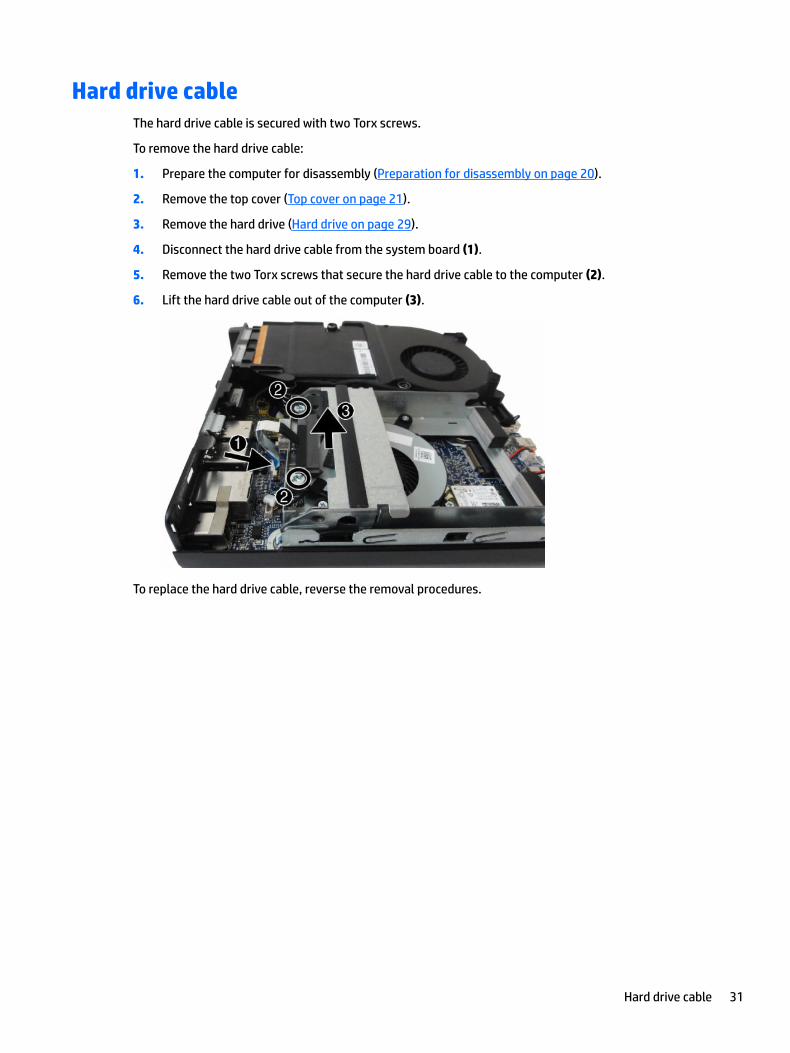
Hard drive cableThe hard drive cable is secured with two Torx screws.
To remove the hard drive cable:
1. Prepare the computer for disassembly (Preparation for disassembly on page 20).
2. Remove the top cover (Top cover on page 21).
3. Remove the hard drive (Hard drive on page 29).
4. Disconnect the hard drive cable from the system board (1).
5. Remove the two Torx screws that secure the hard drive cable to the computer (2).
6. Lift the hard drive cable out of the computer (3).
To replace the hard drive cable, reverse the removal procedures.
Hard drive cable 31
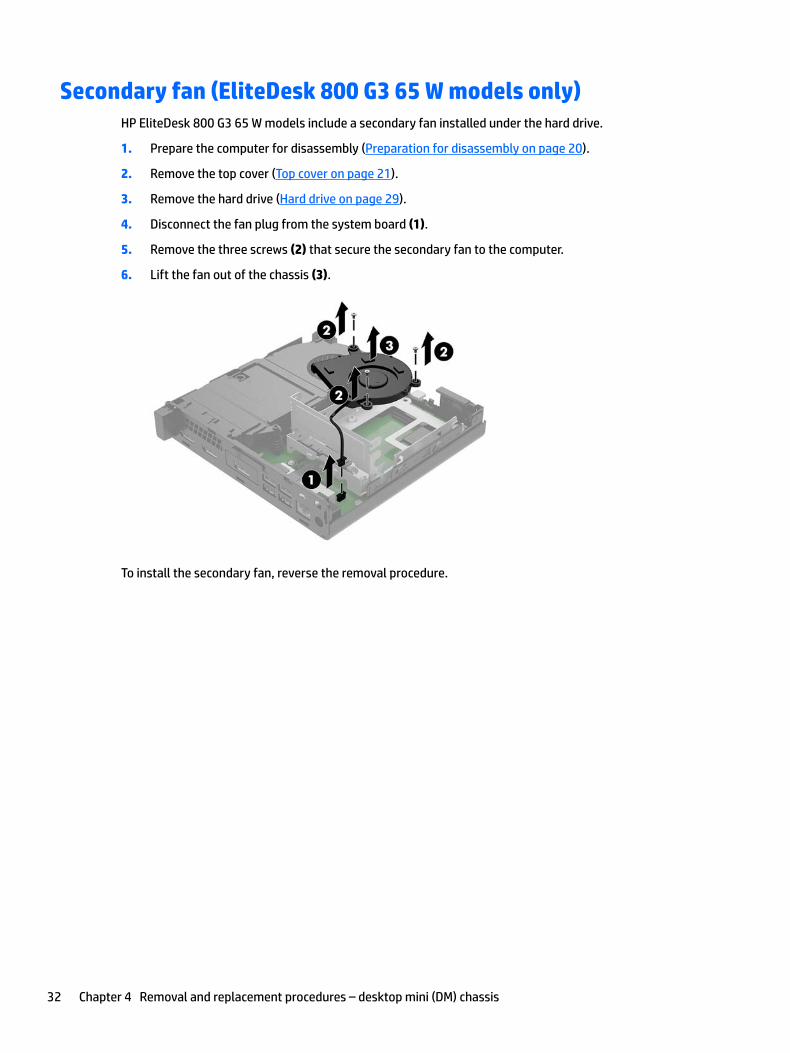
Secondary fan (EliteDesk 800 G3 65 W models only)HP EliteDesk 800 G3 65 W models include a secondary fan installed under the hard drive.
1. Prepare the computer for disassembly (Preparation for disassembly on page 20).
2. Remove the top cover (Top cover on page 21).
3. Remove the hard drive (Hard drive on page 29).
4. Disconnect the fan plug from the system board (1).
5. Remove the three screws (2) that secure the secondary fan to the computer.
6. Lift the fan out of the chassis (3).
To install the secondary fan, reverse the removal procedure.
32 Chapter 4 Removal and replacement procedures – desktop mini (DM) chassis
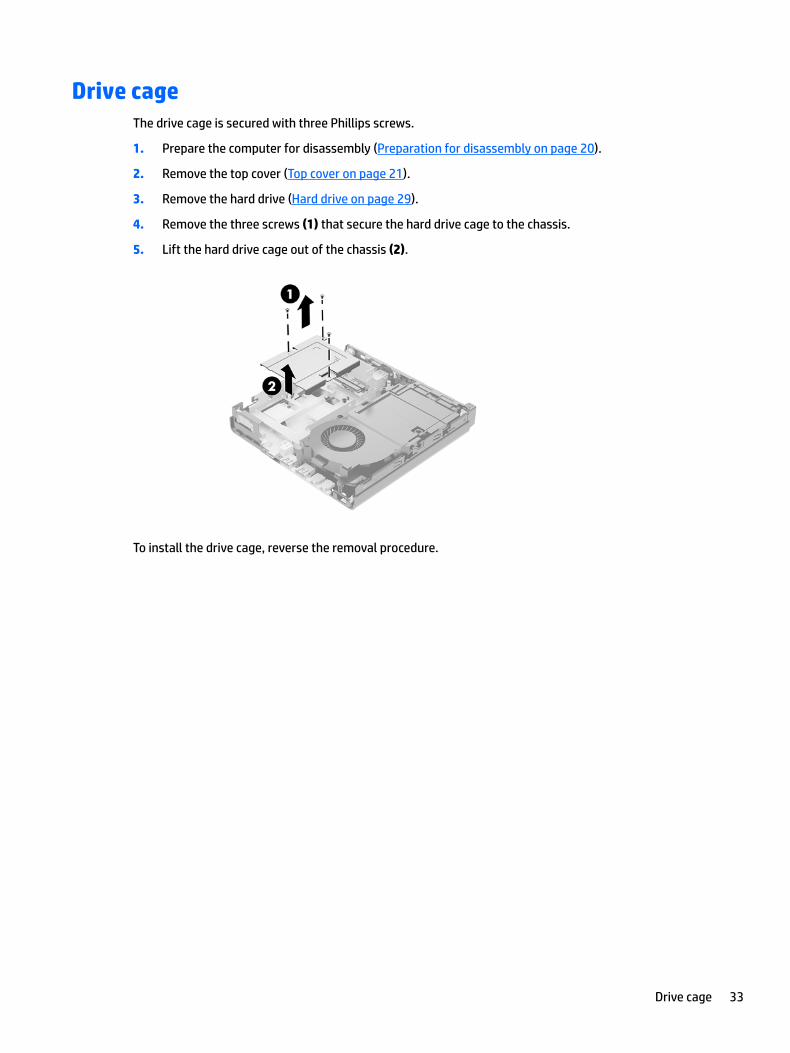
Drive cageThe drive cage is secured with three Phillips screws.
1. Prepare the computer for disassembly (Preparation for disassembly on page 20).
2. Remove the top cover (Top cover on page 21).
3. Remove the hard drive (Hard drive on page 29).
4. Remove the three screws (1) that secure the hard drive cage to the chassis.
5. Lift the hard drive cage out of the chassis (2).
To install the drive cage, reverse the removal procedure.
Drive cage 33
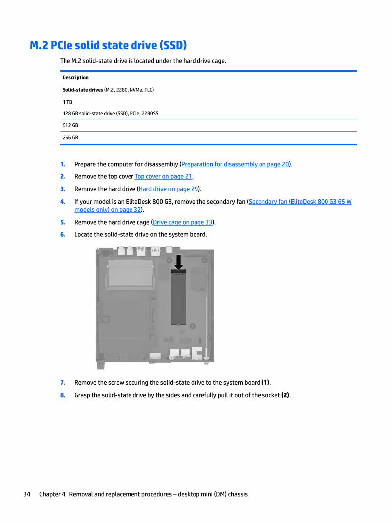
M.2 PCIe solid state drive (SSD)The M.2 solid-state drive is located under the hard drive cage.
Description
Solid-state drives (M.2, 2280, NVMe, TLC)
1 TB
128 GB solid-state drive (SSD), PCIe, 2280SS
512 GB
256 GB
1. Prepare the computer for disassembly (Preparation for disassembly on page 20).
2. Remove the top cover Top cover on page 21.
3. Remove the hard drive (Hard drive on page 29).
4. If your model is an EliteDesk 800 G3, remove the secondary fan (Secondary fan (EliteDesk 800 G3 65 W models only) on page 32).
5. Remove the hard drive cage (Drive cage on page 33).
6. Locate the solid-state drive on the system board.
7. Remove the screw securing the solid-state drive to the system board (1).
8. Grasp the solid-state drive by the sides and carefully pull it out of the socket (2).
34 Chapter 4 Removal and replacement procedures – desktop mini (DM) chassis
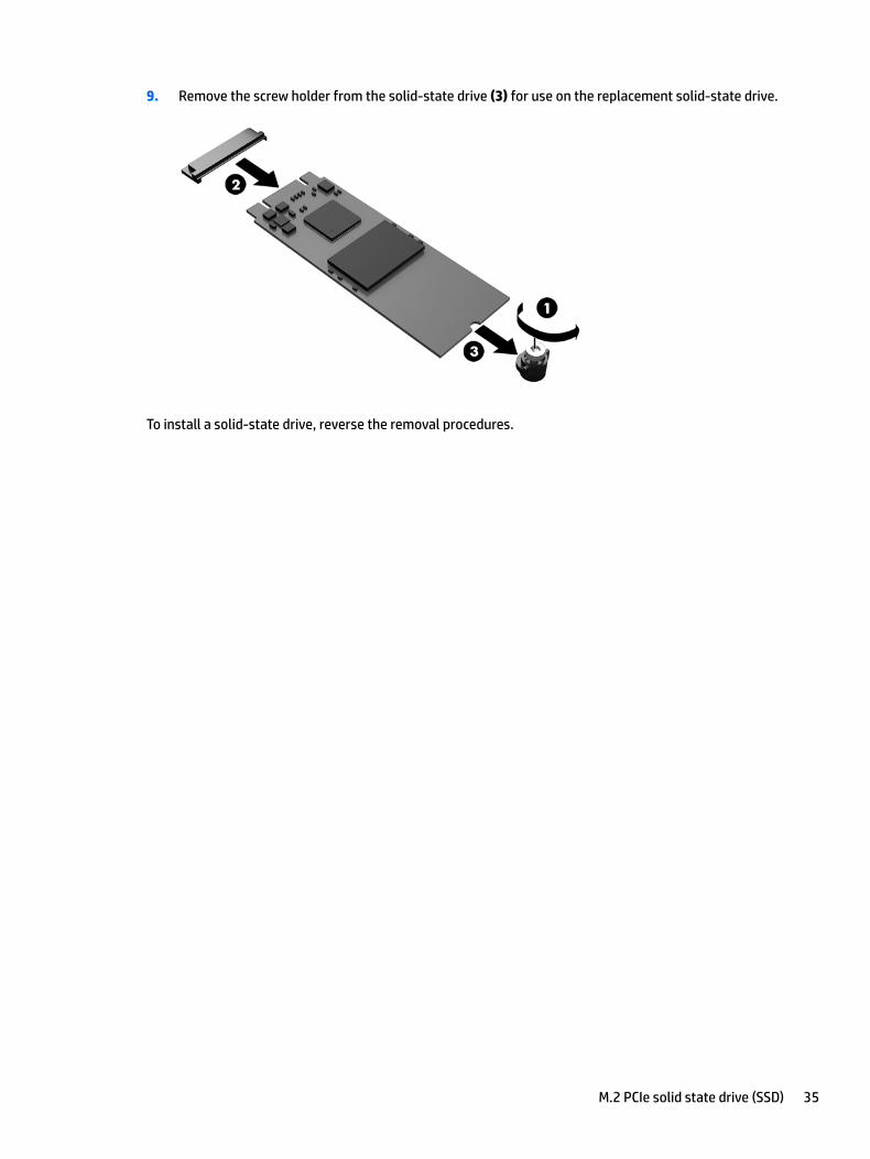
9. Remove the screw holder from the solid-state drive (3) for use on the replacement solid-state drive.
To install a solid-state drive, reverse the removal procedures.
M.2 PCIe solid state drive (SSD) 35
WLAN module
Description
Intel 8265 802.11AC 2x2 Wi-Fi +Bluetooth M.2 Combo Card non-VPro
Intel 7265 802.11AC 2x2 Wi-Fi +Bluetooth M.2 Combo Card non-VPro
Intel 3168 802.11AC 2x2 Wi-Fi +Bluetooth M.2 Combo Card non-VPro
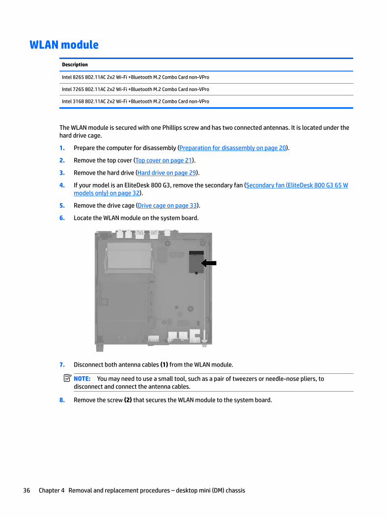
The WLAN module is secured with one Phillips screw and has two connected antennas. It is located under the hard drive cage.
1. Prepare the computer for disassembly (Preparation for disassembly on page 20).
2. Remove the top cover (Top cover on page 21).
3. Remove the hard drive (Hard drive on page 29).
4. If your model is an EliteDesk 800 G3, remove the secondary fan (Secondary fan (EliteDesk 800 G3 65 W models only) on page 32).
5. Remove the drive cage (Drive cage on page 33).
6. Locate the WLAN module on the system board.
7. Disconnect both antenna cables (1) from the WLAN module.
NOTE: You may need to use a small tool, such as a pair of tweezers or needle-nose pliers, to disconnect and connect the antenna cables.
8. Remove the screw (2) that secures the WLAN module to the system board.
36 Chapter 4 Removal and replacement procedures – desktop mini (DM) chassis
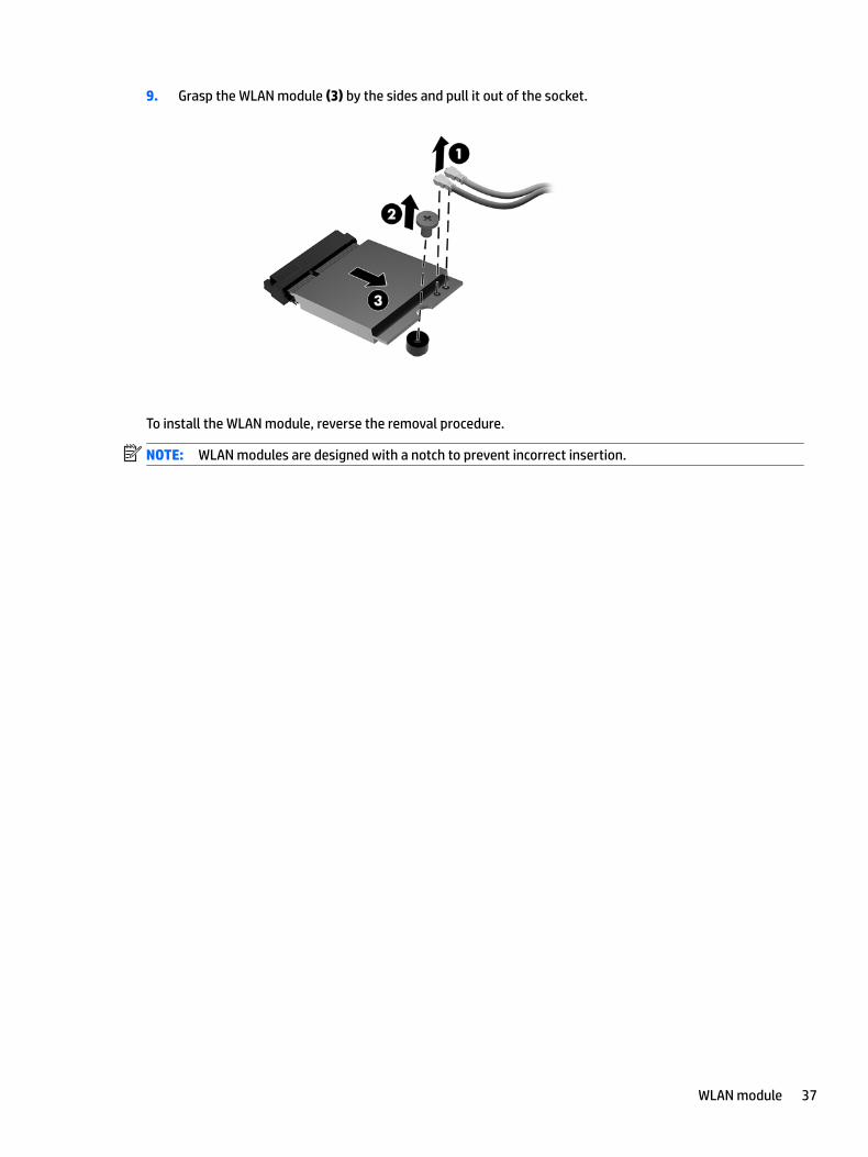
9. Grasp the WLAN module (3) by the sides and pull it out of the socket.
To install the WLAN module, reverse the removal procedure.
NOTE: WLAN modules are designed with a notch to prevent incorrect insertion.
WLAN module 37
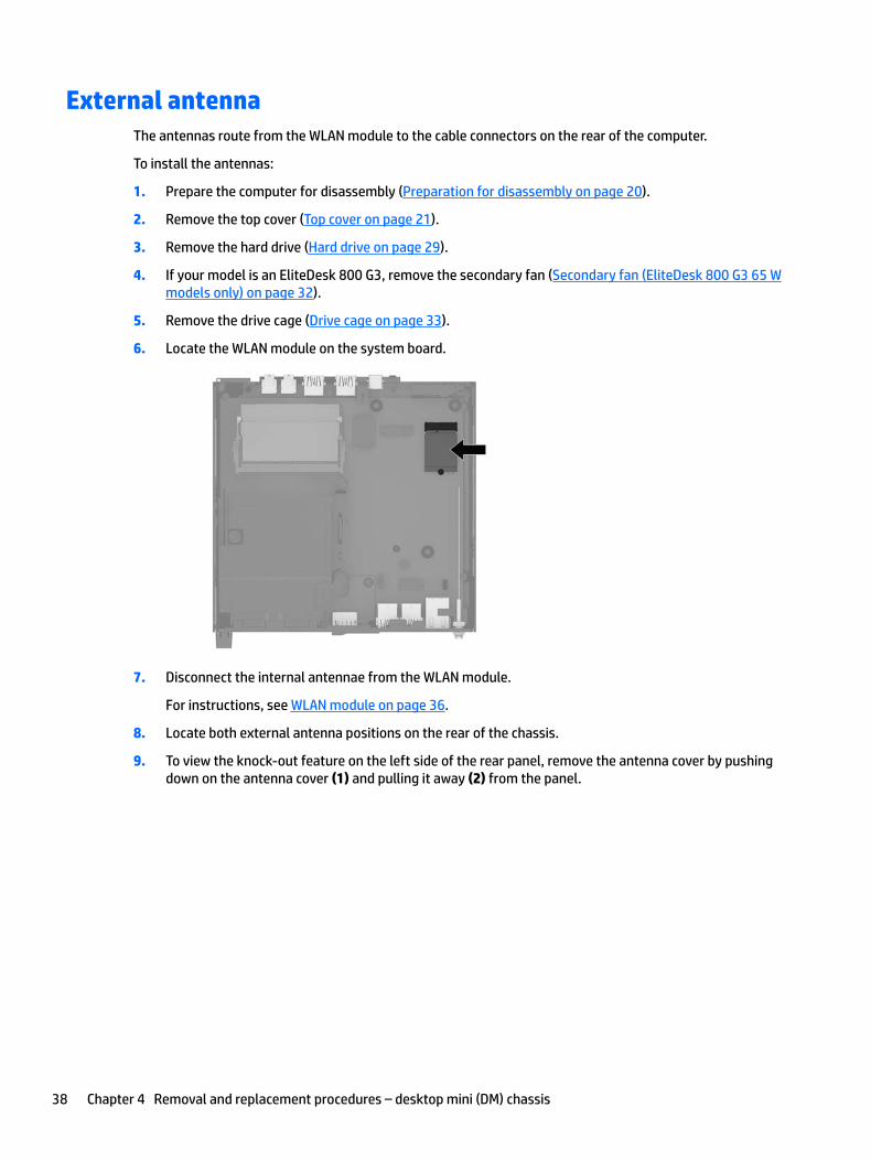
External antennaThe antennas route from the WLAN module to the cable connectors on the rear of the computer.
To install the antennas:
1. Prepare the computer for disassembly (Preparation for disassembly on page 20).
2. Remove the top cover (Top cover on page 21).
3. Remove the hard drive (Hard drive on page 29).
4. If your model is an EliteDesk 800 G3, remove the secondary fan (Secondary fan (EliteDesk 800 G3 65 W models only) on page 32).
5. Remove the drive cage (Drive cage on page 33).
6. Locate the WLAN module on the system board.
7. Disconnect the internal antennae from the WLAN module.
For instructions, see WLAN module on page 36.
8. Locate both external antenna positions on the rear of the chassis.
9. To view the knock-out feature on the left side of the rear panel, remove the antenna cover by pushing down on the antenna cover (1) and pulling it away (2) from the panel.
38 Chapter 4 Removal and replacement procedures – desktop mini (DM) chassis
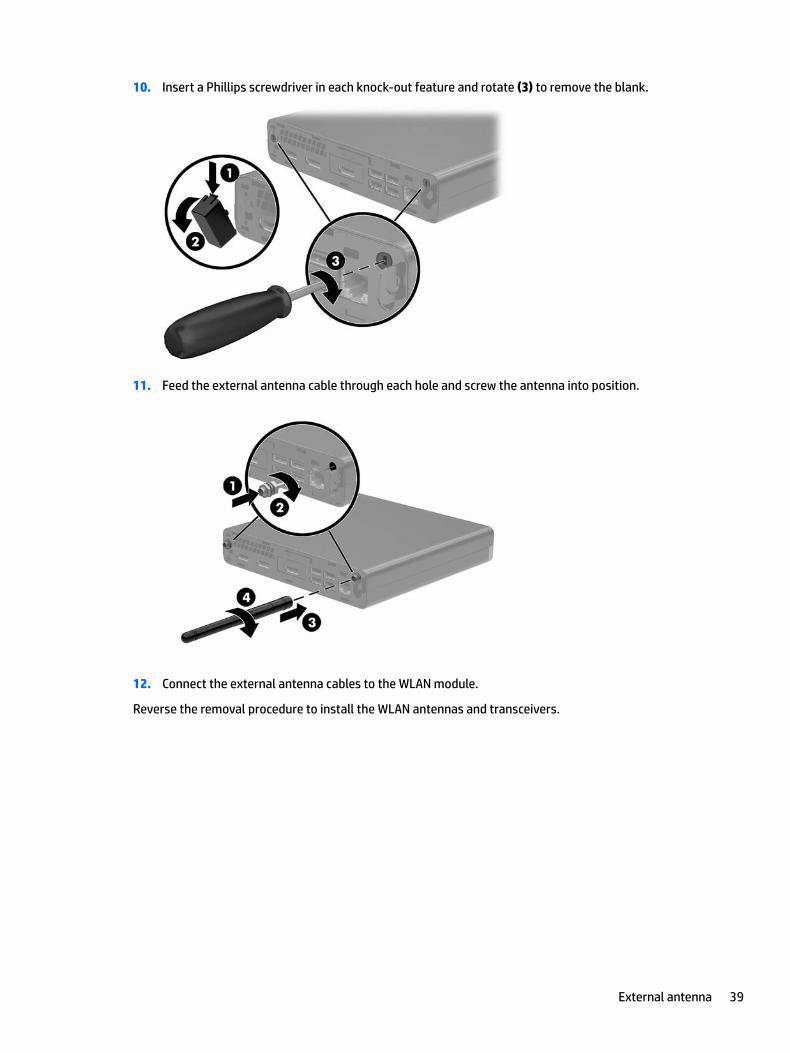
10. Insert a Phillips screwdriver in each knock-out feature and rotate (3) to remove the blank.
11. Feed the external antenna cable through each hole and screw the antenna into position.
12. Connect the external antenna cables to the WLAN module.
Reverse the removal procedure to install the WLAN antennas and transceivers.
External antenna 39
RTC batteryThe battery that comes with the computer provides power to the real-time clock. When replacing the battery, use a battery equivalent to the battery originally installed in the computer. The computer comes with a 3-volt lithium coin cell battery.
WARNING! The computer contains an internal lithium manganese dioxide battery. There is a risk of fire and burns if the battery is not handled properly. To reduce the risk of personal injury:
Do not attempt to recharge the battery.
Do not expose to temperatures higher than 60°C (140ºF).
Do not disassemble, crush, puncture, short external contacts, or dispose of in fire or water.
Replace the battery only with the HP spare designated for this product.
CAUTION: Before replacing the battery, it is important to back up the computer CMOS settings. When the battery is removed or replaced, the CMOS settings will be cleared.
Static electricity can damage the electronic components of the computer or optional equipment. Before beginning these procedures, ensure that you are discharged of static electricity by briefly touching a grounded metal object.
NOTE: The lifetime of the lithium battery can be extended by plugging the computer into a live AC wall socket. The lithium battery is only used when the computer is NOT connected to AC power.
HP encourages customers to recycle used electronic hardware, HP original print cartridges, and rechargeable batteries. For more information about recycling programs, go to http://www.hp.com/recycle.
1. Prepare the computer for disassembly (Preparation for disassembly on page 20).
2. Remove the top cover (Top cover on page 21).
3. Remove the hard drive (Hard drive on page 29).
4. If your model is an EliteDesk 800 G3, remove the secondary fan (Secondary fan (EliteDesk 800 G3 65 W models only) on page 32).
5. Remove the hard drive cage (Drive cage on page 33).
40 Chapter 4 Removal and replacement procedures – desktop mini (DM) chassis
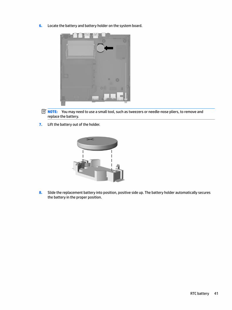
6. Locate the battery and battery holder on the system board.
NOTE: You may need to use a small tool, such as tweezers or needle-nose pliers, to remove and replace the battery.
7. Lift the battery out of the holder.
8. Slide the replacement battery into position, positive side up. The battery holder automatically secures the battery in the proper position.
RTC battery 41
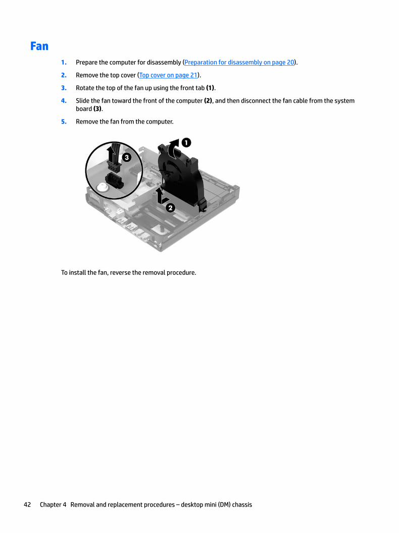
Fan1. Prepare the computer for disassembly (Preparation for disassembly on page 20).
2. Remove the top cover (Top cover on page 21).
3. Rotate the top of the fan up using the front tab (1).
4. Slide the fan toward the front of the computer (2), and then disconnect the fan cable from the system board (3).
5. Remove the fan from the computer.
To install the fan, reverse the removal procedure.
42 Chapter 4 Removal and replacement procedures – desktop mini (DM) chassis
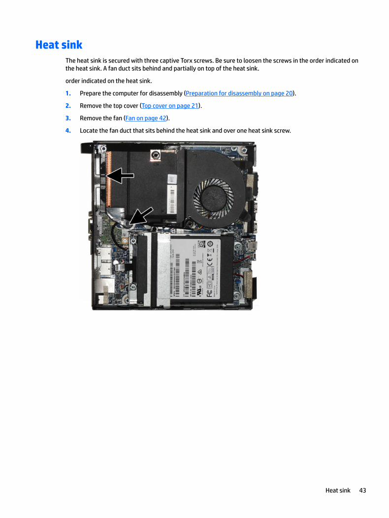
Heat sinkThe heat sink is secured with three captive Torx screws. Be sure to loosen the screws in the order indicated on the heat sink. A fan duct sits behind and partially on top of the heat sink.
order indicated on the heat sink.
1. Prepare the computer for disassembly (Preparation for disassembly on page 20).
2. Remove the top cover (Top cover on page 21).
3. Remove the fan (Fan on page 42).
4. Locate the fan duct that sits behind the heat sink and over one heat sink screw.
Heat sink 43
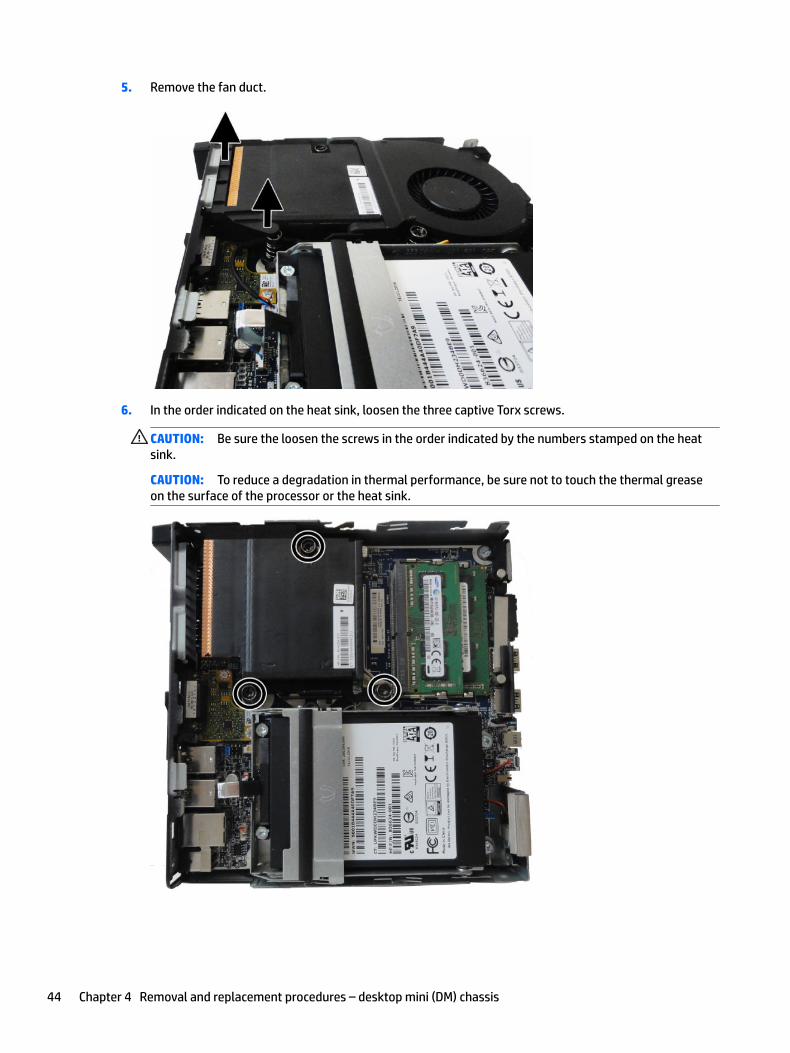
5. Remove the fan duct.
6. In the order indicated on the heat sink, loosen the three captive Torx screws.
CAUTION: Be sure the loosen the screws in the order indicated by the numbers stamped on the heat sink.
CAUTION: To reduce a degradation in thermal performance, be sure not to touch the thermal grease on the surface of the processor or the heat sink.
44 Chapter 4 Removal and replacement procedures – desktop mini (DM) chassis
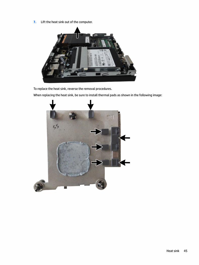
7. Lift the heat sink out of the computer.
To replace the heat sink, reverse the removal procedures.
When replacing the heat sink, be sure to install thermal pads as shown in the following image:
Heat sink 45
Processor
Description
Intel Core i7-7700, 65 W (800 G3 models only)
Intel Core i7-7700T
Intel Core i5-7600T
Intel Core i5-7500, 65 W (800 G3 models only)
Intel Core i5-7500T
Intel Core i3-7320, 65 W (800 G3 models only)
Intel Core i3-7300, 65 W (800 G3 models only)
Intel Core i3-7300T
Intel Core i3-7100, 65 W (800 G3 models only)
Intel Core i3-7100T
Intel Core i7-6700, 65 W (800 G3 models only)
Intel Core i7-6700T
Intel Core i5-6600, 65 W (800 G3 models only)
Intel Core i5-6600T
Intel Core i5-6500, 65 W (800 G3 models only)
Intel Core i7-6500T
Intel Core i3-6100, 65 W (800 G3 models only)
Intel Core i3-6100T
Intel Pentium G4620, 65 W (800 G3 models only)
Intel Pentium G4600, 65 W (800 G3 models only)
Intel Pentium G4600T
Intel Pentium G4560, 65 W (800 G3 models only)
Intel Pentium G4560T
Intel Pentium G3950, 65 W (800 G3 models only)
Intel Celeron G3930, 65 W (800 G3 models only)
Intel Celeron G3930T
1. Prepare the computer for disassembly (Preparation for disassembly on page 20).
2. Remove the top cover (Top cover on page 21).
3. Remove the fan (Fan on page 42).
4. Remove the heat sink (Heat sink on page 43).
5. Rotate the locking lever to its full open position (1).
46 Chapter 4 Removal and replacement procedures – desktop mini (DM) chassis
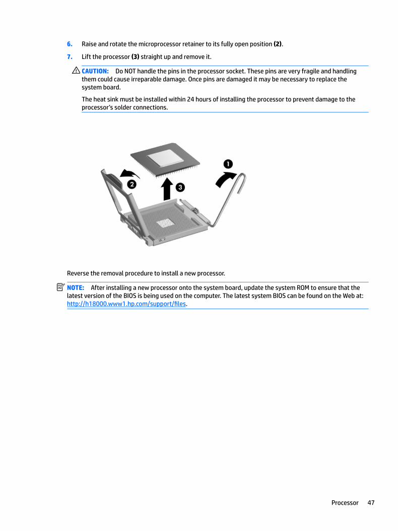
6. Raise and rotate the microprocessor retainer to its fully open position (2).
7. Lift the processor (3) straight up and remove it.
CAUTION: Do NOT handle the pins in the processor socket. These pins are very fragile and handling them could cause irreparable damage. Once pins are damaged it may be necessary to replace the system board.
The heat sink must be installed within 24 hours of installing the processor to prevent damage to the processor’s solder connections.
Reverse the removal procedure to install a new processor.
NOTE: After installing a new processor onto the system board, update the system ROM to ensure that the latest version of the BIOS is being used on the computer. The latest system BIOS can be found on the Web at: http://h18000.www1.hp.com/support/files.
Processor 47
SpeakerA single speaker is located on the left side of the computer behind the front bezel, inside the chassis. It is secured by one Torx screw on the outside and tape on the inside.
To remove the speaker:
1. Prepare the computer for disassembly (Preparation for disassembly on page 20).
2. Remove the top cover (Top cover on page 21).
3. Remove the hard drive (Hard drive on page 29).
4. Remove the hard drive cage (Drive cage on page 33).
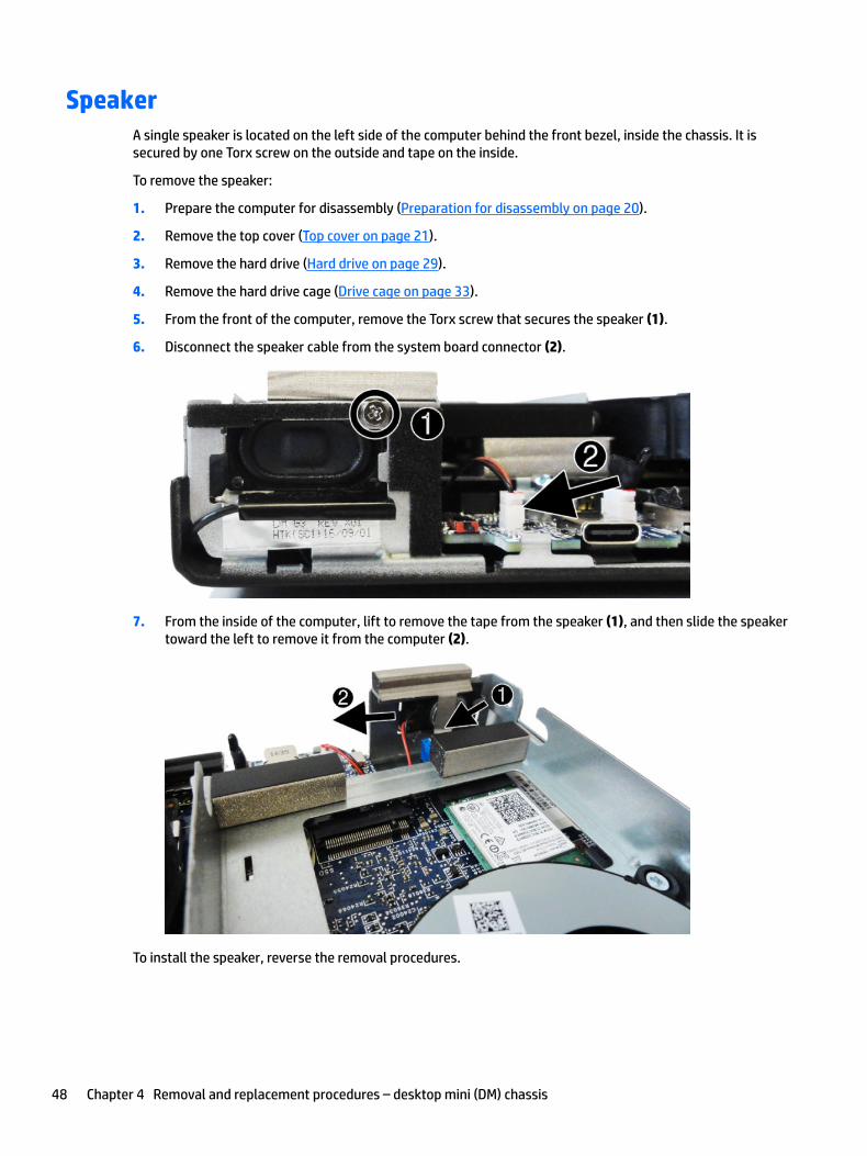
5. From the front of the computer, remove the Torx screw that secures the speaker (1).
6. Disconnect the speaker cable from the system board connector (2).
7. From the inside of the computer, lift to remove the tape from the speaker (1), and then slide the speaker toward the left to remove it from the computer (2).
To install the speaker, reverse the removal procedures.
48 Chapter 4 Removal and replacement procedures – desktop mini (DM) chassis
Option board
Description
Option board, HDMI
Option board, serial port
Option board, DisplayPort
Option board, USB Type-C
Option board, VGA
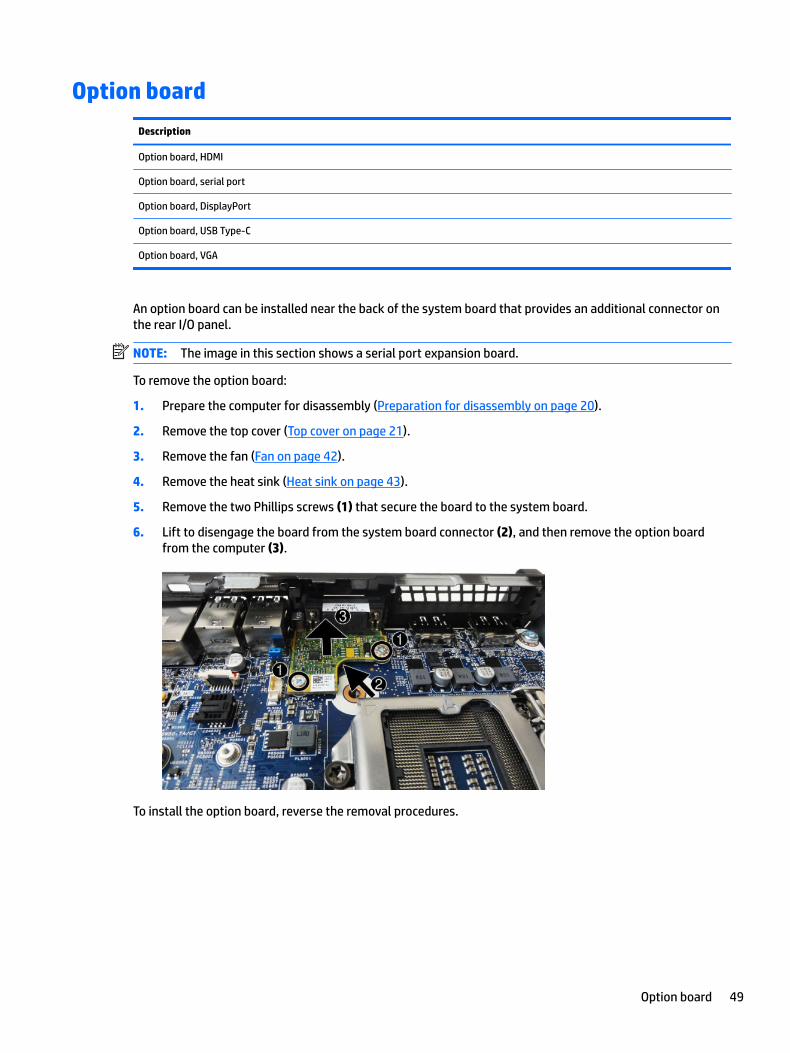
An option board can be installed near the back of the system board that provides an additional connector on the rear I/O panel.
NOTE: The image in this section shows a serial port expansion board.
To remove the option board:
1. Prepare the computer for disassembly (Preparation for disassembly on page 20).
2. Remove the top cover (Top cover on page 21).
3. Remove the fan (Fan on page 42).
4. Remove the heat sink (Heat sink on page 43).
5. Remove the two Phillips screws (1) that secure the board to the system board.
6. Lift to disengage the board from the system board connector (2), and then remove the option board from the computer (3).
To install the option board, reverse the removal procedures.
Option board 49
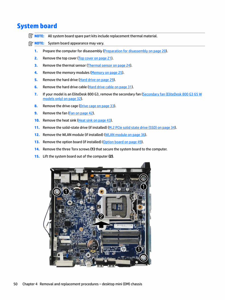
System boardNOTE: All system board spare part kits include replacement thermal material.
NOTE: System board appearance may vary.
1. Prepare the computer for disassembly (Preparation for disassembly on page 20).
2. Remove the top cover (Top cover on page 21).
3. Remove the thermal sensor (Thermal sensor on page 24).
4. Remove the memory modules (Memory on page 25).
5. Remove the hard drive (Hard drive on page 29).
6. Remove the hard drive cable (Hard drive cable on page 31).
7. If your model is an EliteDesk 800 G3, remove the secondary fan (Secondary fan (EliteDesk 800 G3 65 W models only) on page 32).
8. Remove the drive cage (Drive cage on page 33).
9. Remove the fan (Fan on page 42).
10. Remove the heat sink (Heat sink on page 43).
11. Remove the solid-state drive (if installed) (M.2 PCIe solid state drive (SSD) on page 34).
12. Remove the WLAN module (if installed) (WLAN module on page 36).
13. Remove the option board (if installed) (Option board on page 49).
14. Remove the three Torx screws (1) that secure the system board to the computer.
15. Lift the system board out of the computer (2).
50 Chapter 4 Removal and replacement procedures – desktop mini (DM) chassis
To install the system board, reverse the removal procedures.
NOTE: When replacing the system board, you must change the chassis serial number in the BIOS.
Updating SMBIOS Information
When replacing the system board, you must reprogram the SMBIOS information on the affected computer. Failure to reprogram the board will result in eventual failure, such as an activation failure (need to reactivate the system) or a system recovery failure.
To update SMBIOS information in Computer Setup:
1. Turn on or restart the computer.
2. Press Esc while the “Press the ESC key for Startup Menu” message is displayed at the bottom of the screen.
NOTE: If you do not press Esc at the appropriate time, you must restart the computer and again press Esc when the monitor light turns green to access the utility.
3. Press F10 to enter Computer Setup.
4. Go to Main > Set Machine Unique Data.
5. If necessary, press Ctrl+A to initiate edit mode.
6. Edit the fields listed. If the feature byte has data or is not editable, then it was not cleared and cannot be edited.
System ID Setup Page
Setup Field Name Comment Label
Product Name Enter the Model name/number or marketing name.
Flexbuild
Serial Number Enter the Serial Number of Unit. Support
SKU Number Enter the SKU or Product Number including Localization Code.
Support
Asset Tag Enter the 18-byte identifier assigned to the computer.
Support
Feature Byte Enter the Feature Byte string. The feature byte string is case sensitive.
The label includes spaces after every four characters. You can enter or ignore these spaces – their only purpose is to help with data entry. There is a character limitation of 40 bytes per line. When you reach this limit, go
If you make an error during data entry, the data will not validate, and the computer asks you to correct your data input.
Flexbuild
Build ID The Build ID of the unit. Flexbuild
System board 51
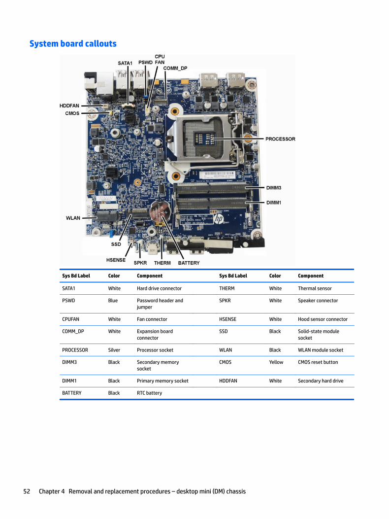
System board callouts
Sys Bd Label Color Component Sys Bd Label Color Component
SATA1 White Hard drive connector THERM White Thermal sensor
PSWD Blue Password header and jumper
SPKR White Speaker connector
CPUFAN White Fan connector HSENSE White Hood sensor connector
COMM_DP White Expansion board connector
SSD Black Solid-state module socket
PROCESSOR Silver Processor socket WLAN Black WLAN module socket
DIMM3 Black Secondary memory socket
CMOS Yellow CMOS reset button
DIMM1 Black Primary memory socket HDDFAN White Secondary hard drive
BATTERY Black RTC battery
52 Chapter 4 Removal and replacement procedures – desktop mini (DM) chassis
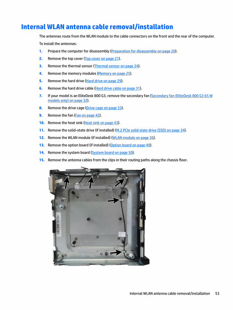
Internal WLAN antenna cable removal/installationThe antennas route from the WLAN module to the cable connectors on the front and the rear of the computer.
To install the antennas:
1. Prepare the computer for disassembly (Preparation for disassembly on page 20).
2. Remove the top cover (Top cover on page 21).
3. Remove the thermal sensor (Thermal sensor on page 24).
4. Remove the memory modules (Memory on page 25).
5. Remove the hard drive (Hard drive on page 29).
6. Remove the hard drive cable (Hard drive cable on page 31).
7. If your model is an EliteDesk 800 G3, remove the secondary fan (Secondary fan (EliteDesk 800 G3 65 W models only) on page 32).
8. Remove the drive cage (Drive cage on page 33).
9. Remove the fan (Fan on page 42).
10. Remove the heat sink (Heat sink on page 43).
11. Remove the solid-state drive (if installed) (M.2 PCIe solid state drive (SSD) on page 34).
12. Remove the WLAN module (if installed) (WLAN module on page 36).
13. Remove the option board (if installed) (Option board on page 49).
14. Remove the system board (System board on page 50).
15. Remove the antenna cables from the clips in their routing paths along the chassis floor.
Internal WLAN antenna cable removal/installation 53
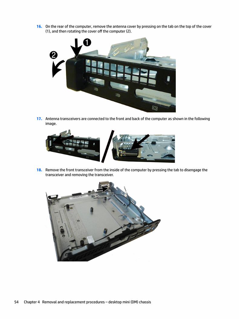
16. On the rear of the computer, remove the antenna cover by pressing on the tab on the top of the cover (1), and then rotating the cover off the computer (2).
17. Antenna transceivers are connected to the front and back of the computer as shown in the following image.
18. Remove the front transceiver from the inside of the computer by pressing the tab to disengage the transceiver and removing the transceiver.
54 Chapter 4 Removal and replacement procedures – desktop mini (DM) chassis
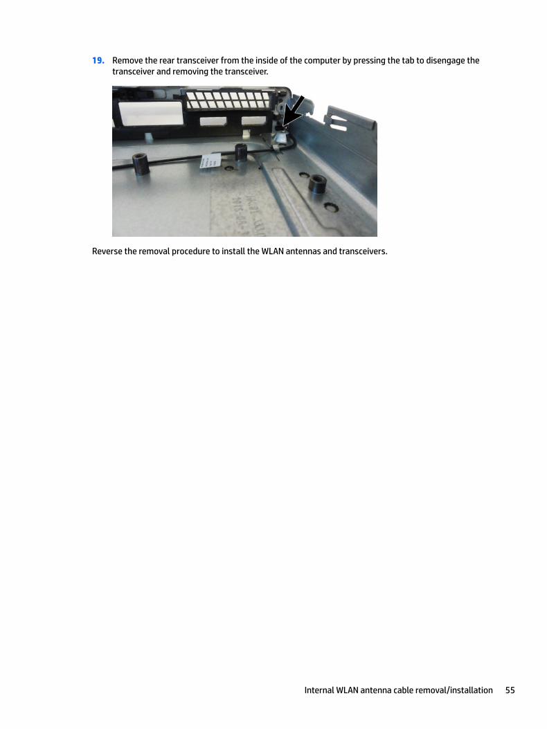
19. Remove the rear transceiver from the inside of the computer by pressing the tab to disengage the transceiver and removing the transceiver.
Reverse the removal procedure to install the WLAN antennas and transceivers.
Internal WLAN antenna cable removal/installation 55
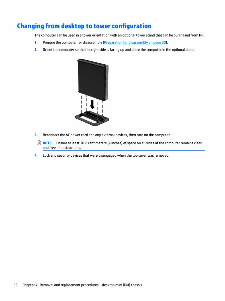
Changing from desktop to tower configurationThe computer can be used in a tower orientation with an optional tower stand that can be purchased from HP.
1. Prepare the computer for disassembly (Preparation for disassembly on page 20).
2. Orient the computer so that its right side is facing up and place the computer in the optional stand.
3. Reconnect the AC power cord and any external devices, then turn on the computer.
NOTE: Ensure at least 10.2 centimeters (4 inches) of space on all sides of the computer remains clear and free of obstructions.
4. Lock any security devices that were disengaged when the top cover was removed.
56 Chapter 4 Removal and replacement procedures – desktop mini (DM) chassis
5 Computer Setup (F10) Utility
Computer Setup (F10) UtilitiesUse Computer Setup (F10) Utility to do the following:
● Change settings from the defaults or restore the settings to default values.
● View the system configuration, including settings for processor, graphics, memory, audio, storage, communications, and input devices.
● Modify the boot order of bootable devices such as hard drives, optical drives, or USB flash media devices.
● (Windows 7 only) Establish an Ownership Tag, the text of which is displayed each time the system is turned on or restarted.
● Enter the Asset Tag or property identification number assigned by the company to this computer.
● Enable the power-on password prompt during system restarts (warm boots) as well as during power-on.
● Establish an administrator password that controls access to the Computer Setup (F10) Utility and the settings described in this section.
● Establish minimum requirements for valid passwords, including length and required types of characters.
● Secure integrated I/O functionality, including the serial, USB, or audio, or embedded NIC, so that they cannot be used until they are unsecured.
● Enable or disable different types of boot sources.
● Configure features such as Secure Boot, power management, virtualization support, and language and keyboard type used in Setup and POST.
● Replicate the system setup by saving system configuration information on a USB device and restoring it on one or more computers.
● Enable or disable DriveLock security or securely erase a hard drive (when supported by drive).
Using Computer Setup (F10) Utilities
Computer Setup can be accessed only by turning the computer on or restarting the system. To access the Computer Setup Utilities menu, complete the following steps:
1. Turn on or restart the computer.
2. Repeatedly press F10 when the monitor light turns green to access the utility.
You can also press Esc to a menu that allows you to access different options available at startup, including the Computer Setup utility.
NOTE: If you do not press F10 at the appropriate time, you must restart the computer and again repeatedly press F10 when the monitor light turns green to access the utility.
3. A choice of four headings appears in the Computer Setup Utilities menu: Main, Security, Advanced, and UEFI Drivers.
NOTE: Selecting UEFI Drivers restarts the computer into the 3rd party option ROM management application. You can access this application directly by pressing F3 during startup.
Computer Setup (F10) Utilities 57
4. Use the arrow (left and right) keys to select the appropriate heading. Use the arrow (up and down) keys to select the option you want, then press Enter. To return to the Computer Setup Utilities menu, press Esc.
5. To apply and save changes, select Main > Save Changes and Exit.
● If you have made changes that you do not want applied, select Ignore Changes and Exit.
● To restore settings from the Advanced and Main menus to original values, select Apply Factory Defaults and Exit.
● To restore settings from the Advanced and Main menus to those previously saved by Save Custom Defaults, select Apply Custom Defaults and Exit. If no custom defaults have been saved, then factory defaults are used.
NOTE: Settings in the Security menu are not modified by Apply Defaults. Those values are reset by Restore Security Settings to Factory Defaults at the bottom of the Security menu.
NOTE: Not all settings shown in the following sections are available for all models
CAUTION: Do NOT turn the computer power OFF while the BIOS is saving the Computer Setup (F10) changes because the settings could become corrupted. It is safe to turn off the computer only after exiting the F10 Setup screen.
58 Chapter 5 Computer Setup (F10) Utility
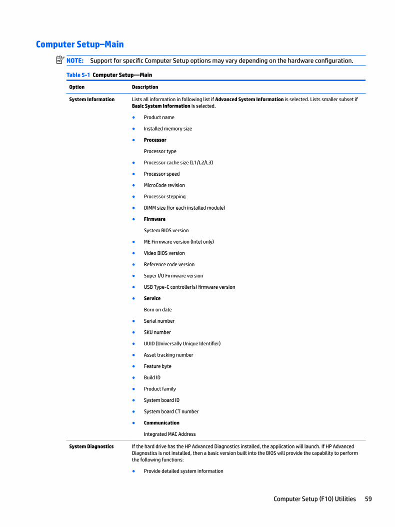
Computer Setup–Main
NOTE: Support for specific Computer Setup options may vary depending on the hardware configuration.
Table 5-1 Computer Setup—Main
Option Description
System Information Lists all information in following list if Advanced System Information is selected. Lists smaller subset if Basic System Information is selected.
● Product name
● Installed memory size
● Processor
Processor type
● Processor cache size (L1/L2/L3)
● Processor speed
● MicroCode revision
● Processor stepping
● DIMM size (for each installed module)
● Firmware
System BIOS version
● ME Firmware version (Intel only)
● Video BIOS version
● Reference code version
● Super I/O Firmware version
● USB Type-C controller(s) firmware version
● Service
Born on date
● Serial number
● SKU number
● UUID (Universally Unique Identifier)
● Asset tracking number
● Feature byte
● Build ID
● Product family
● System board ID
● System board CT number
● Communication
Integrated MAC Address
System Diagnostics If the hard drive has the HP Advanced Diagnostics installed, the application will launch. If HP Advanced Diagnostics is not installed, then a basic version built into the BIOS will provide the capability to perform the following functions:
● Provide detailed system information
Computer Setup (F10) Utilities 59
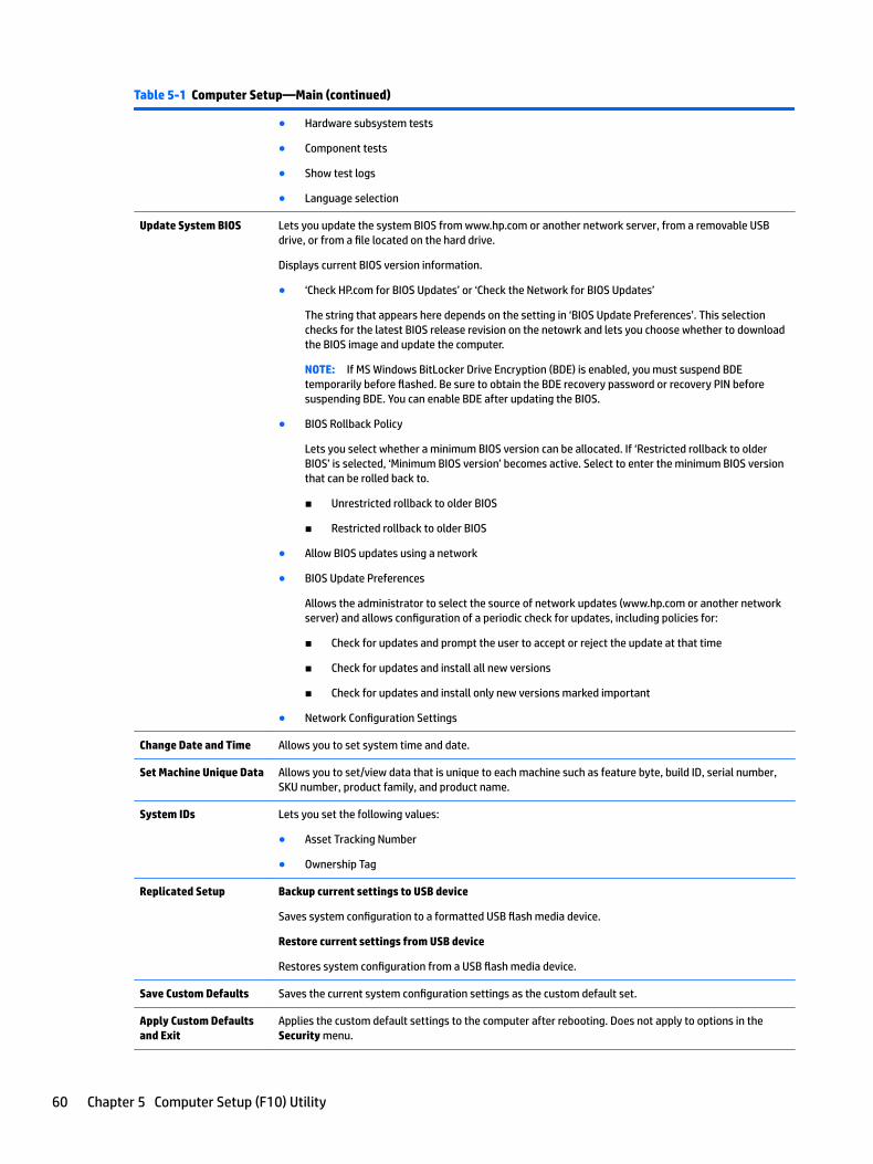
Table 5-1 Computer Setup—Main (continued)
● Hardware subsystem tests
● Component tests
● Show test logs
● Language selection
Update System BIOS Lets you update the system BIOS from www.hp.com or another network server, from a removable USB drive, or from a file located on the hard drive.
Displays current BIOS version information.
● ‘Check HP.com for BIOS Updates’ or ‘Check the Network for BIOS Updates’
The string that appears here depends on the setting in ‘BIOS Update Preferences’. This selection checks for the latest BIOS release revision on the netowrk and lets you choose whether to download the BIOS image and update the computer.
NOTE: If MS Windows BitLocker Drive Encryption (BDE) is enabled, you must suspend BDE temporarily before flashed. Be sure to obtain the BDE recovery password or recovery PIN before suspending BDE. You can enable BDE after updating the BIOS.
● BIOS Rollback Policy
Lets you select whether a minimum BIOS version can be allocated. If ‘Restricted rollback to older BIOS’ is selected, ‘Minimum BIOS version’ becomes active. Select to enter the minimum BIOS version that can be rolled back to.
■ Unrestricted rollback to older BIOS
■ Restricted rollback to older BIOS
● Allow BIOS updates using a network
● BIOS Update Preferences
Allows the administrator to select the source of network updates (www.hp.com or another network server) and allows configuration of a periodic check for updates, including policies for:
■ Check for updates and prompt the user to accept or reject the update at that time
■ Check for updates and install all new versions
■ Check for updates and install only new versions marked important
● Network Configuration Settings
Change Date and Time Allows you to set system time and date.
Set Machine Unique Data Allows you to set/view data that is unique to each machine such as feature byte, build ID, serial number, SKU number, product family, and product name.
System IDs Lets you set the following values:
● Asset Tracking Number
● Ownership Tag
Replicated Setup Backup current settings to USB device
Saves system configuration to a formatted USB flash media device.
Restore current settings from USB device
Restores system configuration from a USB flash media device.
Save Custom Defaults Saves the current system configuration settings as the custom default set.
Apply Custom Defaults and Exit
Applies the custom default settings to the computer after rebooting. Does not apply to options in the Security menu.
60 Chapter 5 Computer Setup (F10) Utility
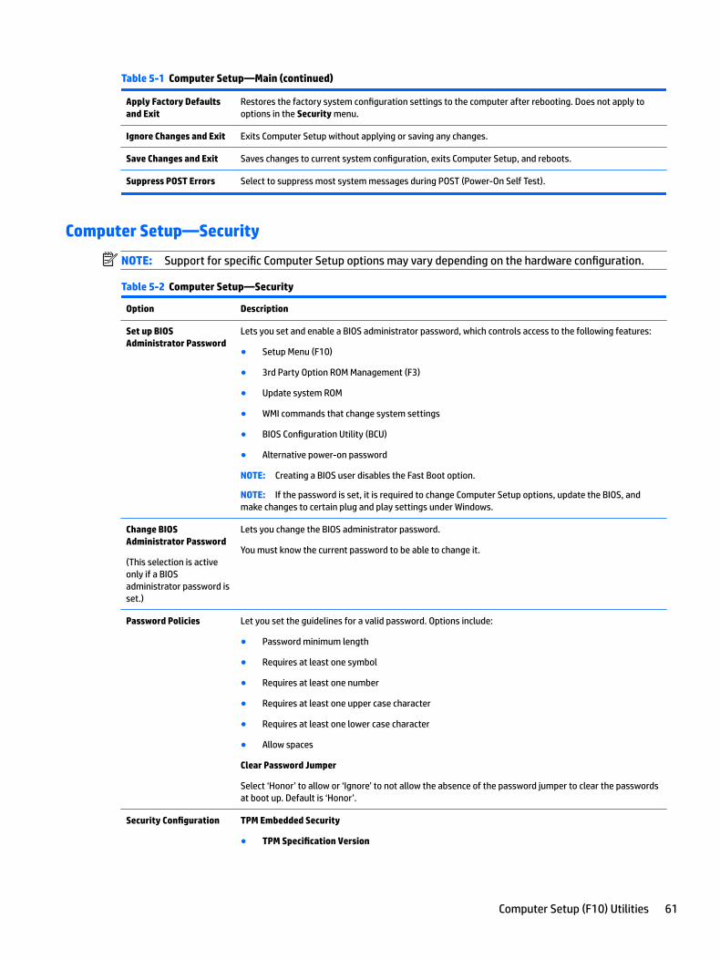
Table 5-1 Computer Setup—Main (continued)
Apply Factory Defaults and Exit
Restores the factory system configuration settings to the computer after rebooting. Does not apply to options in the Security menu.
Ignore Changes and Exit Exits Computer Setup without applying or saving any changes.
Save Changes and Exit Saves changes to current system configuration, exits Computer Setup, and reboots.
Suppress POST Errors Select to suppress most system messages during POST (Power-On Self Test).
Computer Setup—Security
NOTE: Support for specific Computer Setup options may vary depending on the hardware configuration.
Table 5-2 Computer Setup—Security
Option Description
Set up BIOS Administrator Password
Lets you set and enable a BIOS administrator password, which controls access to the following features:
● Setup Menu (F10)
● 3rd Party Option ROM Management (F3)
● Update system ROM
● WMI commands that change system settings
● BIOS Configuration Utility (BCU)
● Alternative power-on password
NOTE: Creating a BIOS user disables the Fast Boot option.
NOTE: If the password is set, it is required to change Computer Setup options, update the BIOS, and make changes to certain plug and play settings under Windows.
Change BIOS Administrator Password
(This selection is active only if a BIOS administrator password is set.)
Lets you change the BIOS administrator password.
You must know the current password to be able to change it.
Password Policies Let you set the guidelines for a valid password. Options include:
● Password minimum length
● Requires at least one symbol
● Requires at least one number
● Requires at least one upper case character
● Requires at least one lower case character
● Allow spaces
Clear Password Jumper
Select ‘Honor’ to allow or ‘Ignore’ to not allow the absence of the password jumper to clear the passwords at boot up. Default is ‘Honor’.
Security Configuration TPM Embedded Security
● TPM Specification Version
Computer Setup (F10) Utilities 61
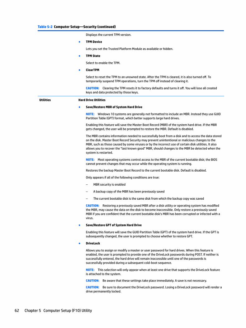
Table 5-2 Computer Setup—Security (continued)
Displays the current TPM version.
● TPM Device
Lets you set the Trusted Platform Module as available or hidden.
● TPM State
Select to enable the TPM.
● ClearTPM
Select to reset the TPM to an unowned state. After the TPM is cleared, it is also turned off. To temporarily suspend TPM operations, turn the TPM off instead of clearing it.
CAUTION: Clearing the TPM resets it to factory defaults and turns it off. You will lose all created keys and data protected by those keys.
Utilities Hard Drive Utilities
● Save/Restore MBR of System Hard Drive
NOTE: Windows 10 systems are generally not formatted to include an MBR. Instead they use GUID Partition Table (GPT) format, which better supports large hard drives.
Enabling this feature will save the Master Boot Record (MBR) of the system hard drive. If the MBR gets changed, the user will be prompted to restore the MBR. Default is disabled.
The MBR contains information needed to successfully boot from a disk and to access the data stored on the disk. Master Boot Record Security may prevent unintentional or malicious changes to the MBR, such as those caused by some viruses or by the incorrect use of certain disk utilities. It also allows you to recover the "last known good" MBR, should changes to the MBR be detected when the system is restarted.
NOTE: Most operating systems control access to the MBR of the current bootable disk; the BIOS cannot prevent changes that may occur while the operating system is running.
Restores the backup Master Boot Record to the current bootable disk. Default is disabled.
Only appears if all of the following conditions are true:
– MBR security is enabled
– A backup copy of the MBR has been previously saved
– The current bootable disk is the same disk from which the backup copy was saved
CAUTION: Restoring a previously saved MBR after a disk utility or operating system has modified the MBR, may cause the data on the disk to become inaccessible. Only restore a previously saved MBR if you are confident that the current bootable disk's MBR has been corrupted or infected with a virus.
● Save/Restore GPT of System Hard Drive
Enabling this feature will save the GUID Partition Table (GPT) of the system hard drive. If the GPT is subsequently changed, the user is prompted to choose whether to restore GPT.
● DriveLock
Allows you to assign or modify a master or user password for hard drives. When this feature is enabled, the user is prompted to provide one of the DriveLock passwords during POST. If neither is successfully entered, the hard drive will remain inaccessible until one of the passwords is successfully provided during a subsequent cold-boot sequence.
NOTE: This selection will only appear when at least one drive that supports the DriveLock feature is attached to the system.
CAUTION: Be aware that these settings take place immediately. A save is not necessary.
CAUTION: Be sure to document the DriveLock password. Losing a DriveLock password will render a drive permanently locked.
62 Chapter 5 Computer Setup (F10) Utility
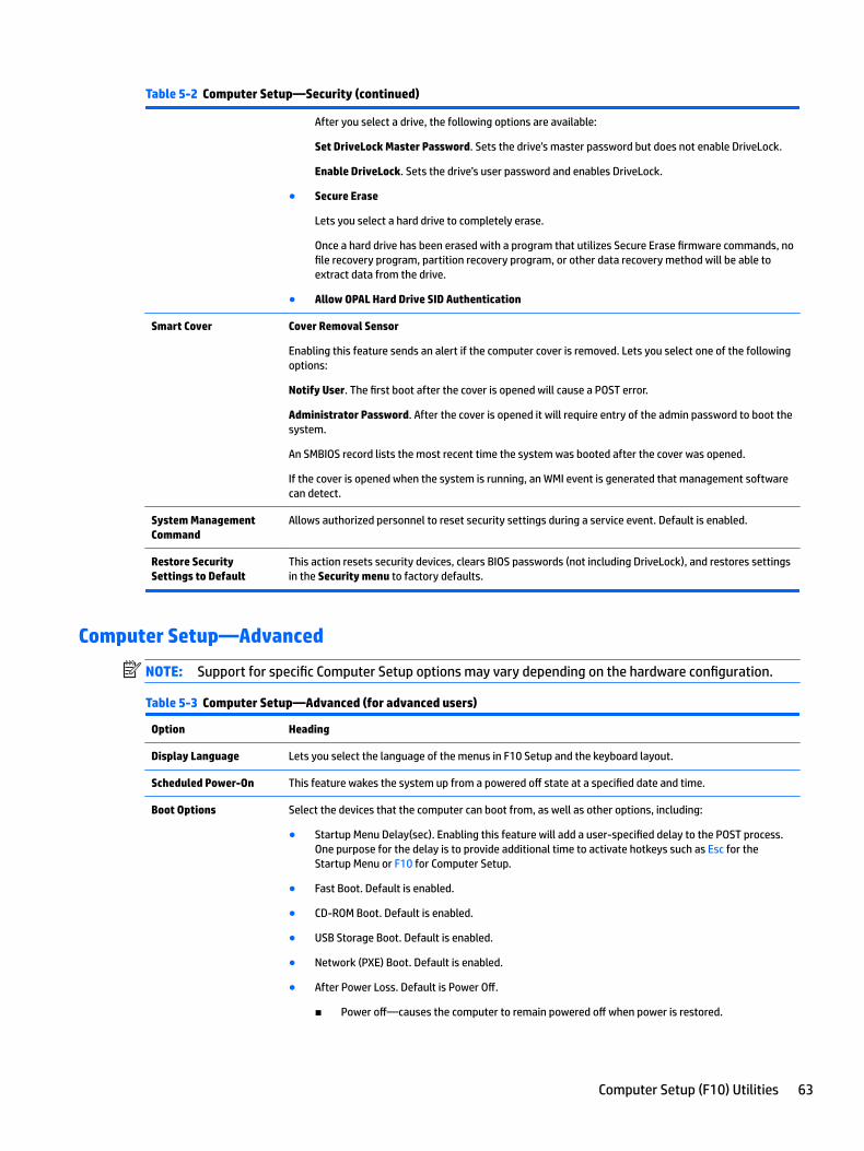
Table 5-2 Computer Setup—Security (continued)
After you select a drive, the following options are available:
Set DriveLock Master Password. Sets the drive’s master password but does not enable DriveLock.
Enable DriveLock. Sets the drive’s user password and enables DriveLock.
● Secure Erase
Lets you select a hard drive to completely erase.
Once a hard drive has been erased with a program that utilizes Secure Erase firmware commands, no file recovery program, partition recovery program, or other data recovery method will be able to extract data from the drive.
● Allow OPAL Hard Drive SID Authentication
Smart Cover Cover Removal Sensor
Enabling this feature sends an alert if the computer cover is removed. Lets you select one of the following options:
Notify User. The first boot after the cover is opened will cause a POST error.
Administrator Password. After the cover is opened it will require entry of the admin password to boot the system.
An SMBIOS record lists the most recent time the system was booted after the cover was opened.
If the cover is opened when the system is running, an WMI event is generated that management software can detect.
System Management Command
Allows authorized personnel to reset security settings during a service event. Default is enabled.
Restore Security Settings to Default
This action resets security devices, clears BIOS passwords (not including DriveLock), and restores settings in the Security menu to factory defaults.
Computer Setup—Advanced
NOTE: Support for specific Computer Setup options may vary depending on the hardware configuration.
Table 5-3 Computer Setup—Advanced (for advanced users)
Option Heading
Display Language Lets you select the language of the menus in F10 Setup and the keyboard layout.
Scheduled Power-On This feature wakes the system up from a powered off state at a specified date and time.
Boot Options Select the devices that the computer can boot from, as well as other options, including:
● Startup Menu Delay(sec). Enabling this feature will add a user-specified delay to the POST process. One purpose for the delay is to provide additional time to activate hotkeys such as Esc for the Startup Menu or F10 for Computer Setup.
● Fast Boot. Default is enabled.
● CD-ROM Boot. Default is enabled.
● USB Storage Boot. Default is enabled.
● Network (PXE) Boot. Default is enabled.
● After Power Loss. Default is Power Off.
■ Power off—causes the computer to remain powered off when power is restored.
Computer Setup (F10) Utilities 63
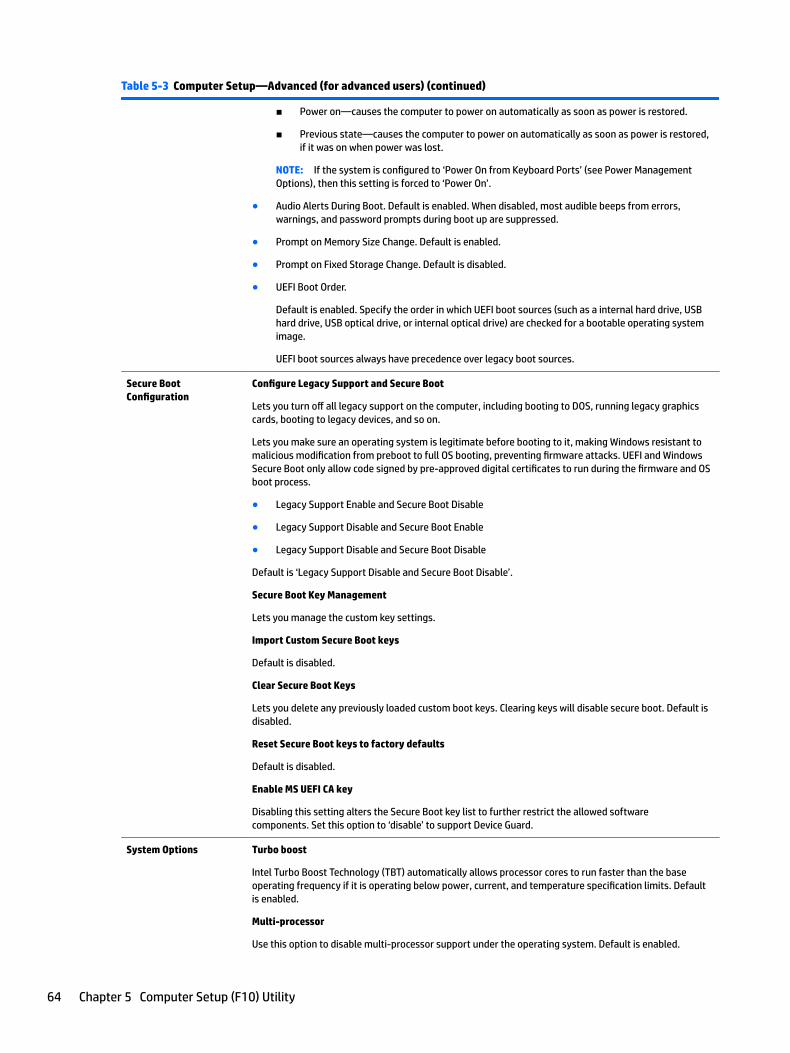
Table 5-3 Computer Setup—Advanced (for advanced users) (continued)
■ Power on—causes the computer to power on automatically as soon as power is restored.
■ Previous state—causes the computer to power on automatically as soon as power is restored, if it was on when power was lost.
NOTE: If the system is configured to ‘Power On from Keyboard Ports’ (see Power Management Options), then this setting is forced to ‘Power On’.
● Audio Alerts During Boot. Default is enabled. When disabled, most audible beeps from errors, warnings, and password prompts during boot up are suppressed.
● Prompt on Memory Size Change. Default is enabled.
● Prompt on Fixed Storage Change. Default is disabled.
● UEFI Boot Order.
Default is enabled. Specify the order in which UEFI boot sources (such as a internal hard drive, USB hard drive, USB optical drive, or internal optical drive) are checked for a bootable operating system image.
UEFI boot sources always have precedence over legacy boot sources.
Secure Boot Configuration
Configure Legacy Support and Secure Boot
Lets you turn off all legacy support on the computer, including booting to DOS, running legacy graphics cards, booting to legacy devices, and so on.
Lets you make sure an operating system is legitimate before booting to it, making Windows resistant to malicious modification from preboot to full OS booting, preventing firmware attacks. UEFI and Windows Secure Boot only allow code signed by pre-approved digital certificates to run during the firmware and OS boot process.
● Legacy Support Enable and Secure Boot Disable
● Legacy Support Disable and Secure Boot Enable
● Legacy Support Disable and Secure Boot Disable
Default is ‘Legacy Support Disable and Secure Boot Disable’.
Secure Boot Key Management
Lets you manage the custom key settings.
Import Custom Secure Boot keys
Default is disabled.
Clear Secure Boot Keys
Lets you delete any previously loaded custom boot keys. Clearing keys will disable secure boot. Default is disabled.
Reset Secure Boot keys to factory defaults
Default is disabled.
Enable MS UEFI CA key
Disabling this setting alters the Secure Boot key list to further restrict the allowed software components. Set this option to ‘disable’ to support Device Guard.
System Options Turbo boost
Intel Turbo Boost Technology (TBT) automatically allows processor cores to run faster than the base operating frequency if it is operating below power, current, and temperature specification limits. Default is enabled.
Multi-processor
Use this option to disable multi-processor support under the operating system. Default is enabled.
64 Chapter 5 Computer Setup (F10) Utility
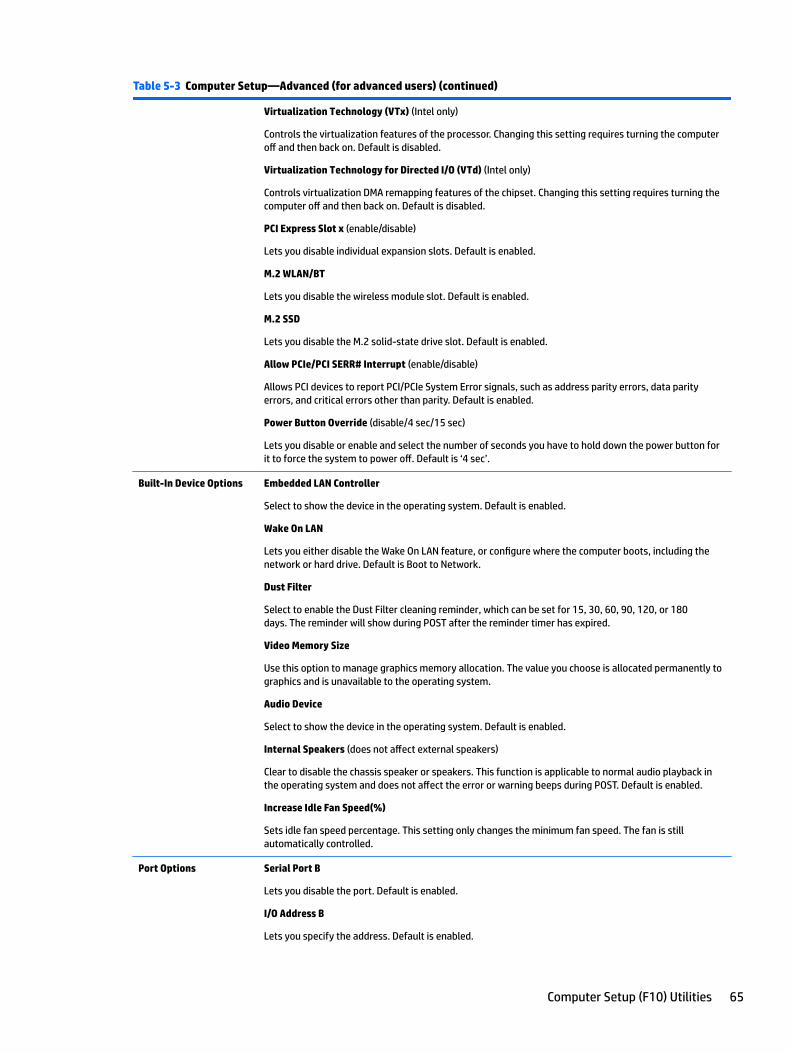
Table 5-3 Computer Setup—Advanced (for advanced users) (continued)
Virtualization Technology (VTx) (Intel only)
Controls the virtualization features of the processor. Changing this setting requires turning the computer off and then back on. Default is disabled.
Virtualization Technology for Directed I/O (VTd) (Intel only)
Controls virtualization DMA remapping features of the chipset. Changing this setting requires turning the computer off and then back on. Default is disabled.
PCI Express Slot x (enable/disable)
Lets you disable individual expansion slots. Default is enabled.
M.2 WLAN/BT
Lets you disable the wireless module slot. Default is enabled.
M.2 SSD
Lets you disable the M.2 solid-state drive slot. Default is enabled.
Allow PCIe/PCI SERR# Interrupt (enable/disable)
Allows PCI devices to report PCI/PCIe System Error signals, such as address parity errors, data parity errors, and critical errors other than parity. Default is enabled.
Power Button Override (disable/4 sec/15 sec)
Lets you disable or enable and select the number of seconds you have to hold down the power button for it to force the system to power off. Default is ‘4 sec’.
Built-In Device Options Embedded LAN Controller
Select to show the device in the operating system. Default is enabled.
Wake On LAN
Lets you either disable the Wake On LAN feature, or configure where the computer boots, including the network or hard drive. Default is Boot to Network.
Dust Filter
Select to enable the Dust Filter cleaning reminder, which can be set for 15, 30, 60, 90, 120, or 180 days. The reminder will show during POST after the reminder timer has expired.
Video Memory Size
Use this option to manage graphics memory allocation. The value you choose is allocated permanently to graphics and is unavailable to the operating system.
Audio Device
Select to show the device in the operating system. Default is enabled.
Internal Speakers (does not affect external speakers)
Clear to disable the chassis speaker or speakers. This function is applicable to normal audio playback in the operating system and does not affect the error or warning beeps during POST. Default is enabled.
Increase Idle Fan Speed(%)
Sets idle fan speed percentage. This setting only changes the minimum fan speed. The fan is still automatically controlled.
Port Options Serial Port B
Lets you disable the port. Default is enabled.
I/O Address B
Lets you specify the address. Default is enabled.
Computer Setup (F10) Utilities 65
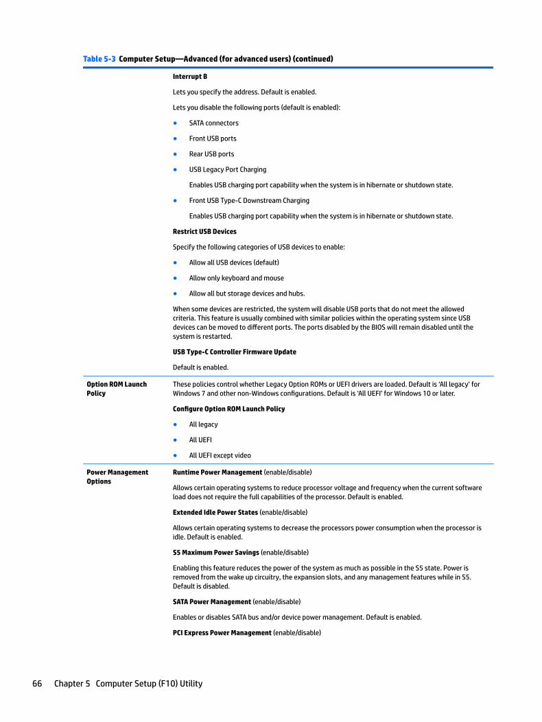
Table 5-3 Computer Setup—Advanced (for advanced users) (continued)
Interrupt B
Lets you specify the address. Default is enabled.
Lets you disable the following ports (default is enabled):
● SATA connectors
● Front USB ports
● Rear USB ports
● USB Legacy Port Charging
Enables USB charging port capability when the system is in hibernate or shutdown state.
● Front USB Type-C Downstream Charging
Enables USB charging port capability when the system is in hibernate or shutdown state.
Restrict USB Devices
Specify the following categories of USB devices to enable:
● Allow all USB devices (default)
● Allow only keyboard and mouse
● Allow all but storage devices and hubs.
When some devices are restricted, the system will disable USB ports that do not meet the allowed criteria. This feature is usually combined with similar policies within the operating system since USB devices can be moved to different ports. The ports disabled by the BIOS will remain disabled until the system is restarted.
USB Type-C Controller Firmware Update
Default is enabled.
Option ROM Launch Policy
These policies control whether Legacy Option ROMs or UEFI drivers are loaded. Default is ‘All legacy’ for Windows 7 and other non-Windows configurations. Default is ‘All UEFI’ for Windows 10 or later.
Configure Option ROM Launch Policy
● All legacy
● All UEFI
● All UEFI except video
Power Management Options
Runtime Power Management (enable/disable)
Allows certain operating systems to reduce processor voltage and frequency when the current software load does not require the full capabilities of the processor. Default is enabled.
Extended Idle Power States (enable/disable)
Allows certain operating systems to decrease the processors power consumption when the processor is idle. Default is enabled.
S5 Maximum Power Savings (enable/disable)
Enabling this feature reduces the power of the system as much as possible in the S5 state. Power is removed from the wake up circuitry, the expansion slots, and any management features while in S5. Default is disabled.
SATA Power Management (enable/disable)
Enables or disables SATA bus and/or device power management. Default is enabled.
PCI Express Power Management (enable/disable)
66 Chapter 5 Computer Setup (F10) Utility
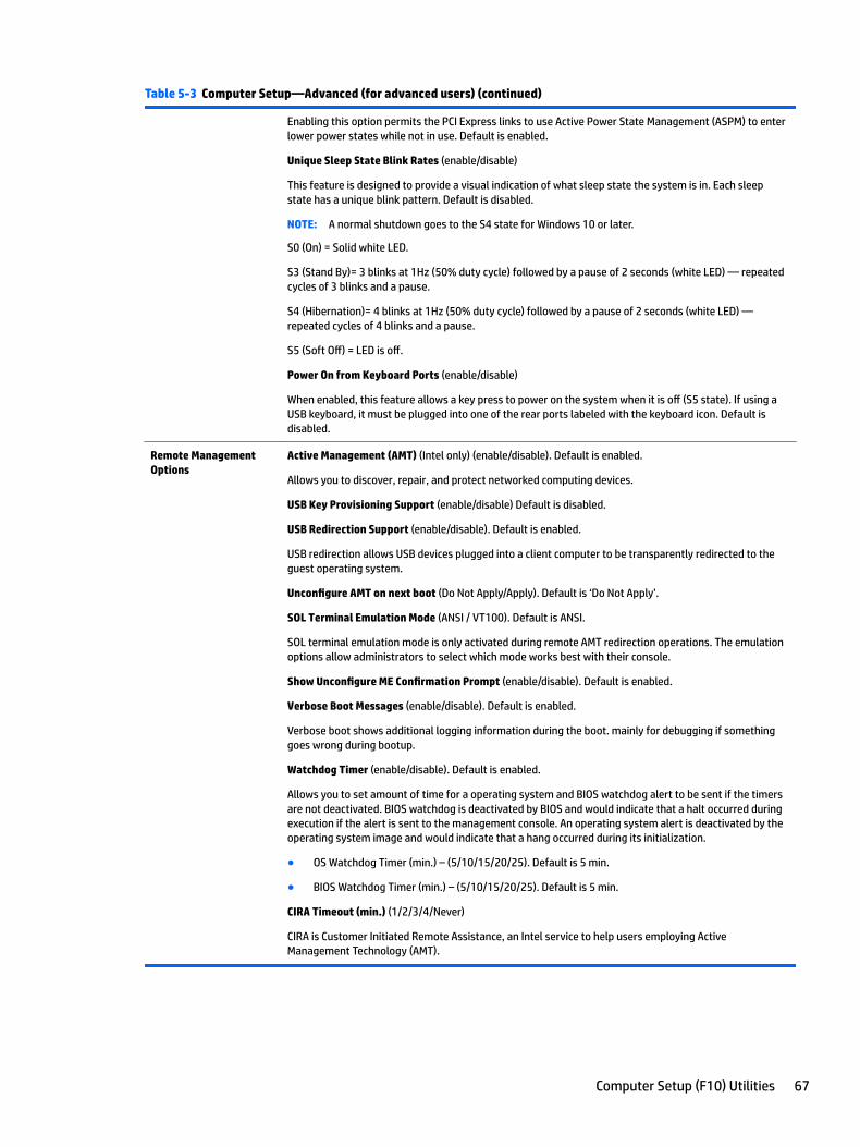
Table 5-3 Computer Setup—Advanced (for advanced users) (continued)
Enabling this option permits the PCI Express links to use Active Power State Management (ASPM) to enter lower power states while not in use. Default is enabled.
Unique Sleep State Blink Rates (enable/disable)
This feature is designed to provide a visual indication of what sleep state the system is in. Each sleep state has a unique blink pattern. Default is disabled.
NOTE: A normal shutdown goes to the S4 state for Windows 10 or later.
S0 (On) = Solid white LED.
S3 (Stand By)= 3 blinks at 1Hz (50% duty cycle) followed by a pause of 2 seconds (white LED) — repeated cycles of 3 blinks and a pause.
S4 (Hibernation)= 4 blinks at 1Hz (50% duty cycle) followed by a pause of 2 seconds (white LED) — repeated cycles of 4 blinks and a pause.
S5 (Soft Off) = LED is off.
Power On from Keyboard Ports (enable/disable)
When enabled, this feature allows a key press to power on the system when it is off (S5 state). If using a USB keyboard, it must be plugged into one of the rear ports labeled with the keyboard icon. Default is disabled.
Remote Management Options
Active Management (AMT) (Intel only) (enable/disable). Default is enabled.
Allows you to discover, repair, and protect networked computing devices.
USB Key Provisioning Support (enable/disable) Default is disabled.
USB Redirection Support (enable/disable). Default is enabled.
USB redirection allows USB devices plugged into a client computer to be transparently redirected to the guest operating system.
Unconfigure AMT on next boot (Do Not Apply/Apply). Default is ‘Do Not Apply’.
SOL Terminal Emulation Mode (ANSI / VT100). Default is ANSI.
SOL terminal emulation mode is only activated during remote AMT redirection operations. The emulation options allow administrators to select which mode works best with their console.
Show Unconfigure ME Confirmation Prompt (enable/disable). Default is enabled.
Verbose Boot Messages (enable/disable). Default is enabled.
Verbose boot shows additional logging information during the boot. mainly for debugging if something goes wrong during bootup.
Watchdog Timer (enable/disable). Default is enabled.
Allows you to set amount of time for a operating system and BIOS watchdog alert to be sent if the timers are not deactivated. BIOS watchdog is deactivated by BIOS and would indicate that a halt occurred during execution if the alert is sent to the management console. An operating system alert is deactivated by the operating system image and would indicate that a hang occurred during its initialization.
● OS Watchdog Timer (min.) – (5/10/15/20/25). Default is 5 min.
● BIOS Watchdog Timer (min.) – (5/10/15/20/25). Default is 5 min.
CIRA Timeout (min.) (1/2/3/4/Never)
CIRA is Customer Initiated Remote Assistance, an Intel service to help users employing Active Management Technology (AMT).
Computer Setup (F10) Utilities 67
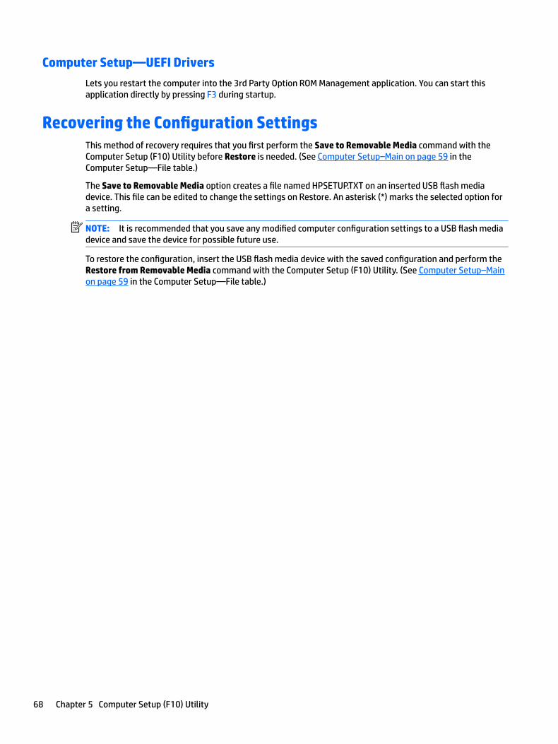
Computer Setup—UEFI Drivers
Lets you restart the computer into the 3rd Party Option ROM Management application. You can start this application directly by pressing F3 during startup.
Recovering the Configuration SettingsThis method of recovery requires that you first perform the Save to Removable Media command with the Computer Setup (F10) Utility before Restore is needed. (See Computer Setup–Main on page 59 in the Computer Setup—File table.)
The Save to Removable Media option creates a file named HPSETUP.TXT on an inserted USB flash media device. This file can be edited to change the settings on Restore. An asterisk (*) marks the selected option for a setting.
NOTE: It is recommended that you save any modified computer configuration settings to a USB flash media device and save the device for possible future use.
To restore the configuration, insert the USB flash media device with the saved configuration and perform the Restore from Removable Media command with the Computer Setup (F10) Utility. (See Computer Setup–Main on page 59 in the Computer Setup—File table.)
68 Chapter 5 Computer Setup (F10) Utility
6 Troubleshooting without diagnostics
This chapter provides information on how to identify and correct minor problems, such as USB devices, hard drive, optical drive, graphics, audio, memory, and software problems. If you encounter problems with the computer, refer to the tables in this chapter for probable causes and recommended solutions.
NOTE: For information on specific error messages that may appear on the screen during Power-On Self-Test (POST) at startup, refer to POST error messages and diagnostic front panel LEDs and audible codes on page 97.
Safety and comfortWARNING! Misuse of the computer or failure to establish a safe and comfortable work environment may result in discomfort or serious injury. Refer to the Safety & Comfort Guide at http://www.hp.com/ergo for more information on choosing a workspace and creating a safe and comfortable work environment. For more information, refer to the Safety & Regulatory Information guide.
Before you call for technical supportIf you are having problems with the computer, try the appropriate solutions below to try to isolate the exact problem before calling for technical support.
● Run the HP diagnostic tool.
● Run the hard drive self-test in Computer Setup. Refer to Computer Setup (F10) Utility on page 57 for more information.
● Check the Power LED on the front of the computer to see if it is flashing red. The flashing lights are error codes that will help you diagnose the problem. Refer to POST error messages and diagnostic front panel LEDs and audible codes on page 97 for more information.
● If the screen is blank, plug the monitor into a different video port on the computer if one is available. Or, replace the monitor with a monitor that you know is functioning properly.
● If you are working on a network, plug another computer with a different cable into the network connection. There may be a problem with the network plug or cable.
● If you recently added new hardware, remove the hardware and see if the computer functions properly.
● If you recently installed new software, uninstall the software and see if the computer functions properly.
● Boot the computer to the Safe Mode to see if it will boot without all of the drivers loaded. When booting the operating system, use “Last Known Configuration.”
● Refer to the comprehensive online technical support at http://www.hp.com/support.
● Refer to Helpful hints on page 70 in this guide.
To assist you in resolving problems online, HP Instant Support Professional Edition provides you with self-solve diagnostics. If you need to contact HP support, use HP Instant Support Professional Edition's online chat feature. Access HP Instant Support Professional Edition at: http://www.hp.com/go/ispe.
Access the Business Support Center (BSC) at http://www.hp.com/go/bizsupport for the latest online support information, software and drivers, proactive notification, and worldwide community of peers and HP experts.
Safety and comfort 69
If it becomes necessary to call for technical assistance, be prepared to do the following to ensure that your service call is handled properly:
● Be in front of your computer when you call.
● Write down the computer serial number, product ID number, and monitor serial number before calling.
● Spend time troubleshooting the problem with the service technician.
● Remove any hardware that was recently added to your system.
● Remove any software that was recently installed.
● Restore the system from the Recovery Disc Set that you created or restore the system to its original factory condition in System Software Requirement Disks (SSRD).
CAUTION: Restoring the system will erase all data on the hard drive. Be sure to back up all data files before running the restore process.
NOTE: For sales information and warranty upgrades (Care Packs), call your local authorized service provider or dealer.
Helpful hintsIf you encounter problems with the computer, monitor, or software, see the following list of general suggestions before taking further action:
● Check that the computer and monitor are plugged into a working electrical outlet.
● Check that the voltage select switch (some models) is set to the appropriate voltage for your region (115V or 230V).
● Check that the computer is turned on and the white power light is on.
● Check that the monitor is turned on and the green monitor light is on.
● Check the Power LED on the front of the computer to see if it is flashing red. The flashing lights are error codes that will help you diagnose the problem. Refer to POST error messages and diagnostic front panel LEDs and audible codes on page 97 for more information.
● Turn up the brightness and contrast controls of the monitor if the monitor is dim.
● Press and hold any key. If the system beeps, then the keyboard should be operating correctly.
● Check all cable connections for loose connections or incorrect connections.
● Wake the computer by pressing any key on the keyboard or pressing the power button. If the system remains in suspend mode, shut down the computer by pressing and holding the power button for at least four seconds then press the power button again to restart the computer. If the system will not shut down, unplug the power cord, wait a few seconds, then plug it in again. The computer will restart if it is set to power on automatically as soon as power is restored in Computer Setup. If it does not restart, press the power button to start the computer.
● Reconfigure the computer after installing a non-plug and play expansion board or other option. See Solving hardware installation problems on page 87 for instructions.
● Be sure that all the needed device drivers have been installed. For example, if you are using a printer, you need a driver for that model printer.
● Remove all bootable media (CD/DVD or USB device) from the system before turning it on.
70 Chapter 6 Troubleshooting without diagnostics
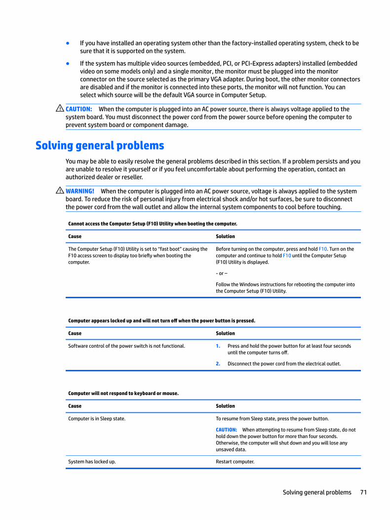
● If you have installed an operating system other than the factory-installed operating system, check to be sure that it is supported on the system.
● If the system has multiple video sources (embedded, PCI, or PCI-Express adapters) installed (embedded video on some models only) and a single monitor, the monitor must be plugged into the monitor connector on the source selected as the primary VGA adapter. During boot, the other monitor connectors are disabled and if the monitor is connected into these ports, the monitor will not function. You can select which source will be the default VGA source in Computer Setup.
CAUTION: When the computer is plugged into an AC power source, there is always voltage applied to the system board. You must disconnect the power cord from the power source before opening the computer to prevent system board or component damage.
Solving general problemsYou may be able to easily resolve the general problems described in this section. If a problem persists and you are unable to resolve it yourself or if you feel uncomfortable about performing the operation, contact an authorized dealer or reseller.
WARNING! When the computer is plugged into an AC power source, voltage is always applied to the system board. To reduce the risk of personal injury from electrical shock and/or hot surfaces, be sure to disconnect the power cord from the wall outlet and allow the internal system components to cool before touching.
Cannot access the Computer Setup (F10) Utility when booting the computer.
Cause Solution
The Computer Setup (F10) Utility is set to “fast boot” causing the F10 access screen to display too briefly when booting the computer.
Before turning on the computer, press and hold F10. Turn on the computer and continue to hold F10 until the Computer Setup (F10) Utility is displayed.
- or –
Follow the Windows instructions for rebooting the computer into the Computer Setup (F10) Utility.
Computer appears locked up and will not turn off when the power button is pressed.
Cause Solution
Software control of the power switch is not functional. 1. Press and hold the power button for at least four seconds until the computer turns off.
2. Disconnect the power cord from the electrical outlet.
Computer will not respond to keyboard or mouse.
Cause Solution
Computer is in Sleep state. To resume from Sleep state, press the power button.
CAUTION: When attempting to resume from Sleep state, do not hold down the power button for more than four seconds. Otherwise, the computer will shut down and you will lose any unsaved data.
System has locked up. Restart computer.
Solving general problems 71
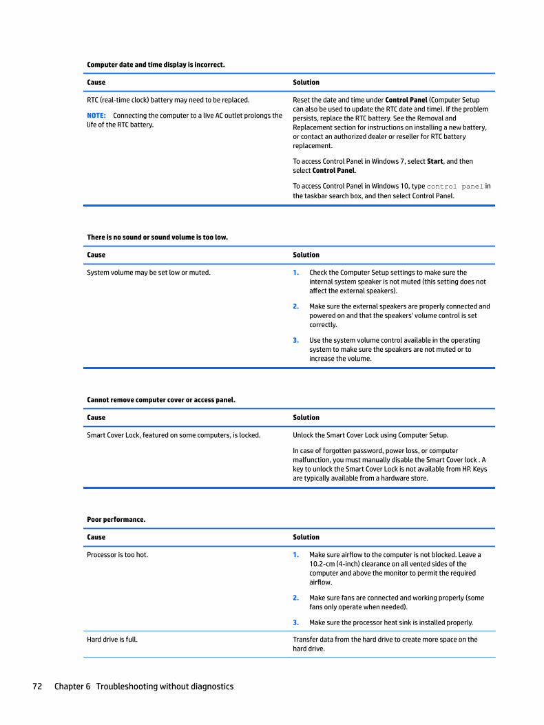
Computer date and time display is incorrect.
Cause Solution
RTC (real-time clock) battery may need to be replaced.
NOTE: Connecting the computer to a live AC outlet prolongs the life of the RTC battery.
Reset the date and time under Control Panel (Computer Setup can also be used to update the RTC date and time). If the problem persists, replace the RTC battery. See the Removal and Replacement section for instructions on installing a new battery, or contact an authorized dealer or reseller for RTC battery replacement.
To access Control Panel in Windows 7, select Start, and then select Control Panel.
To access Control Panel in Windows 10, type control panel in the taskbar search box, and then select Control Panel.
There is no sound or sound volume is too low.
Cause Solution
System volume may be set low or muted. 1. Check the Computer Setup settings to make sure the internal system speaker is not muted (this setting does not affect the external speakers).
2. Make sure the external speakers are properly connected and powered on and that the speakers' volume control is set correctly.
3. Use the system volume control available in the operating system to make sure the speakers are not muted or to increase the volume.
Cannot remove computer cover or access panel.
Cause Solution
Smart Cover Lock, featured on some computers, is locked. Unlock the Smart Cover Lock using Computer Setup.
In case of forgotten password, power loss, or computer malfunction, you must manually disable the Smart Cover lock . A key to unlock the Smart Cover Lock is not available from HP. Keys are typically available from a hardware store.
Poor performance.
Cause Solution
Processor is too hot. 1. Make sure airflow to the computer is not blocked. Leave a 10.2-cm (4-inch) clearance on all vented sides of the computer and above the monitor to permit the required airflow.
2. Make sure fans are connected and working properly (some fans only operate when needed).
3. Make sure the processor heat sink is installed properly.
Hard drive is full. Transfer data from the hard drive to create more space on the hard drive.
72 Chapter 6 Troubleshooting without diagnostics
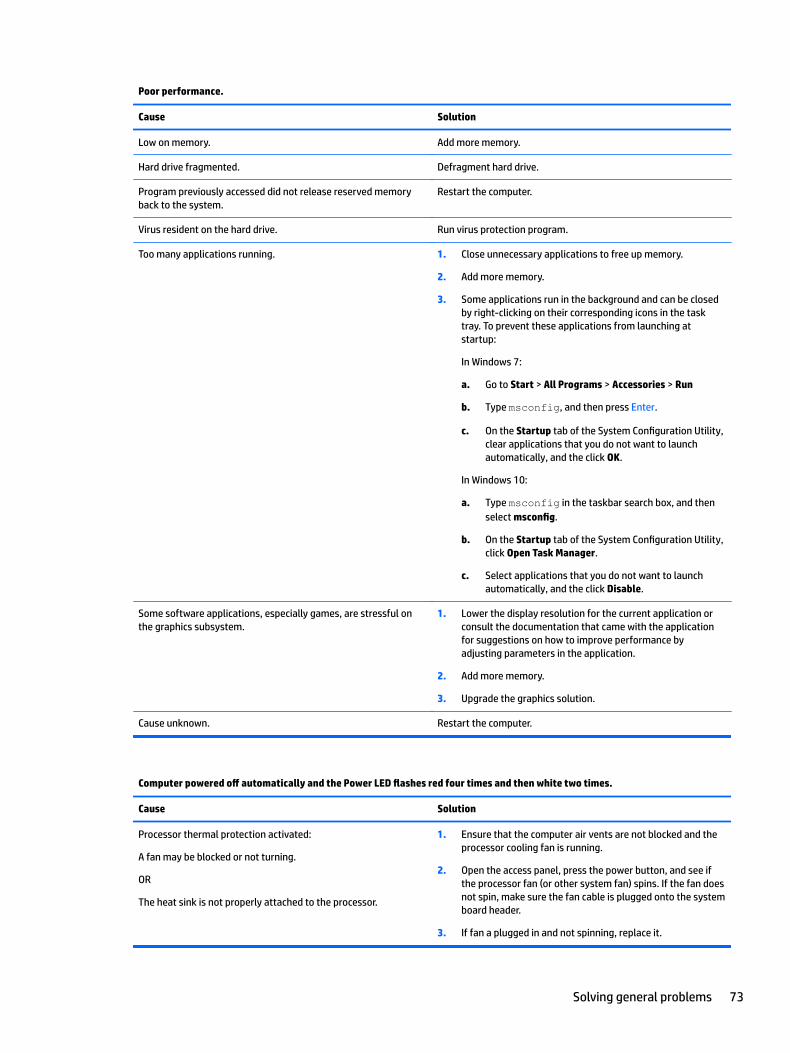
Poor performance.
Cause Solution
Low on memory. Add more memory.
Hard drive fragmented. Defragment hard drive.
Program previously accessed did not release reserved memory back to the system.
Restart the computer.
Virus resident on the hard drive. Run virus protection program.
Too many applications running. 1. Close unnecessary applications to free up memory.
2. Add more memory.
3. Some applications run in the background and can be closed by right-clicking on their corresponding icons in the task tray. To prevent these applications from launching at startup:
In Windows 7:
a. Go to Start > All Programs > Accessories > Run
b. Type msconfig, and then press Enter.
c. On the Startup tab of the System Configuration Utility, clear applications that you do not want to launch automatically, and the click OK.
In Windows 10:
a. Type msconfig in the taskbar search box, and then select msconfig.
b. On the Startup tab of the System Configuration Utility, click Open Task Manager.
c. Select applications that you do not want to launch automatically, and the click Disable.
Some software applications, especially games, are stressful on the graphics subsystem.
1. Lower the display resolution for the current application or consult the documentation that came with the application for suggestions on how to improve performance by adjusting parameters in the application.
2. Add more memory.
3. Upgrade the graphics solution.
Cause unknown. Restart the computer.
Computer powered off automatically and the Power LED flashes red four times and then white two times.
Cause Solution
Processor thermal protection activated:
A fan may be blocked or not turning.
OR
The heat sink is not properly attached to the processor.
1. Ensure that the computer air vents are not blocked and the processor cooling fan is running.
2. Open the access panel, press the power button, and see if the processor fan (or other system fan) spins. If the fan does not spin, make sure the fan cable is plugged onto the system board header.
3. If fan a plugged in and not spinning, replace it.
Solving general problems 73
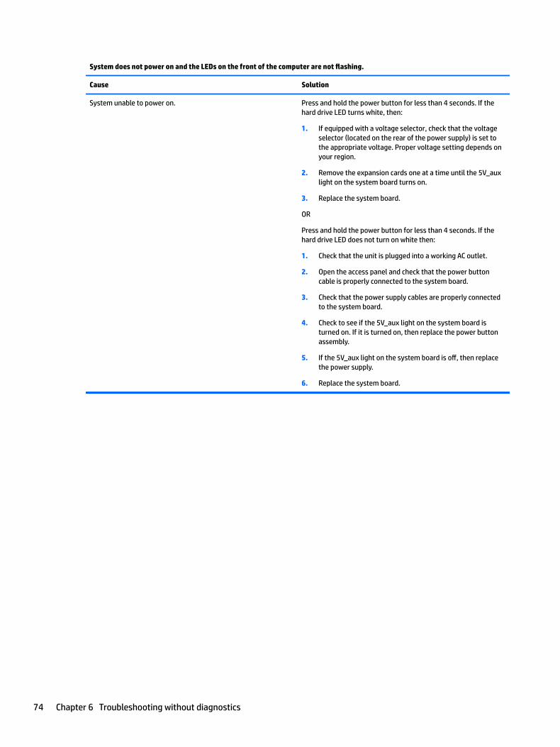
System does not power on and the LEDs on the front of the computer are not flashing.
Cause Solution
System unable to power on. Press and hold the power button for less than 4 seconds. If the hard drive LED turns white, then:
1. If equipped with a voltage selector, check that the voltage selector (located on the rear of the power supply) is set to the appropriate voltage. Proper voltage setting depends on your region.
2. Remove the expansion cards one at a time until the 5V_aux light on the system board turns on.
3. Replace the system board.
OR
Press and hold the power button for less than 4 seconds. If the hard drive LED does not turn on white then:
1. Check that the unit is plugged into a working AC outlet.
2. Open the access panel and check that the power button cable is properly connected to the system board.
3. Check that the power supply cables are properly connected to the system board.
4. Check to see if the 5V_aux light on the system board is turned on. If it is turned on, then replace the power button assembly.
5. If the 5V_aux light on the system board is off, then replace the power supply.
6. Replace the system board.
74 Chapter 6 Troubleshooting without diagnostics
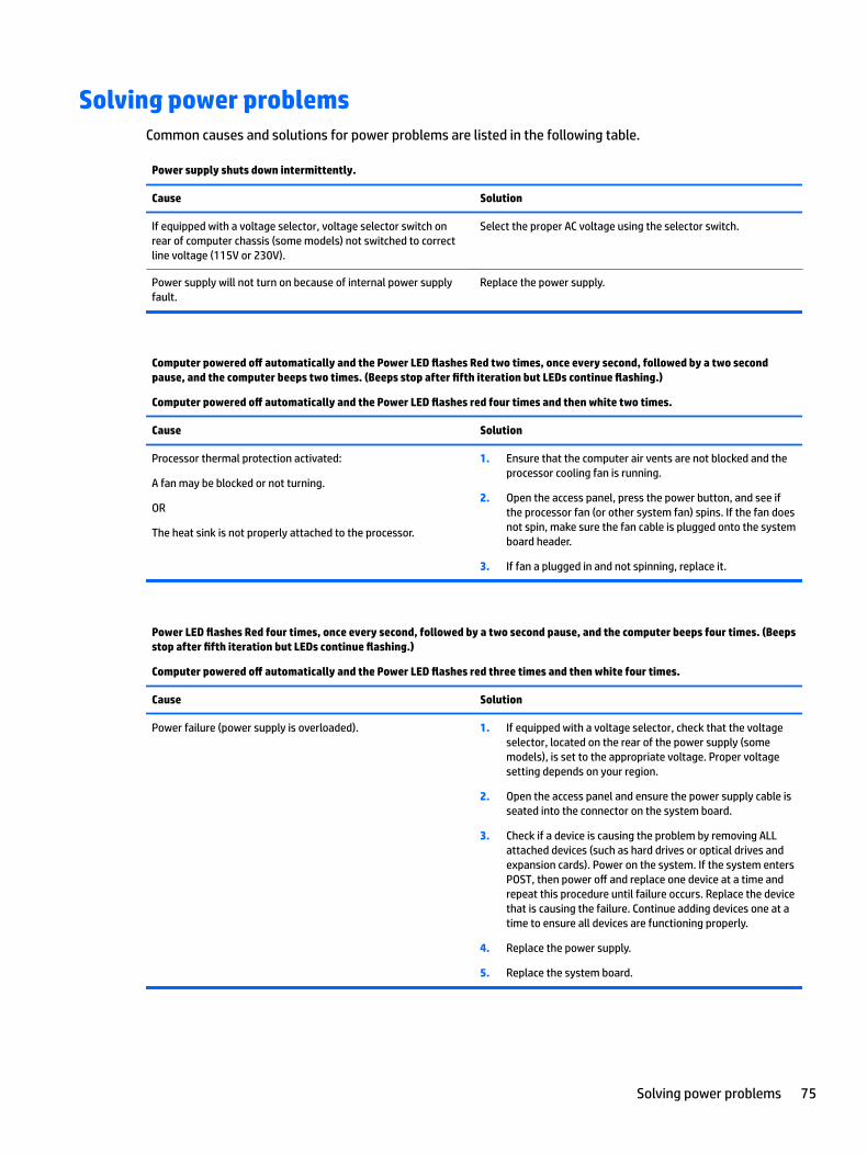
Solving power problemsCommon causes and solutions for power problems are listed in the following table.
Power supply shuts down intermittently.
Cause Solution
If equipped with a voltage selector, voltage selector switch on rear of computer chassis (some models) not switched to correct line voltage (115V or 230V).
Select the proper AC voltage using the selector switch.
Power supply will not turn on because of internal power supply fault.
Replace the power supply.
Computer powered off automatically and the Power LED flashes Red two times, once every second, followed by a two second pause, and the computer beeps two times. (Beeps stop after fifth iteration but LEDs continue flashing.)
Computer powered off automatically and the Power LED flashes red four times and then white two times.
Cause Solution
Processor thermal protection activated:
A fan may be blocked or not turning.
OR
The heat sink is not properly attached to the processor.
1. Ensure that the computer air vents are not blocked and the processor cooling fan is running.
2. Open the access panel, press the power button, and see if the processor fan (or other system fan) spins. If the fan does not spin, make sure the fan cable is plugged onto the system board header.
3. If fan a plugged in and not spinning, replace it.
Power LED flashes Red four times, once every second, followed by a two second pause, and the computer beeps four times. (Beeps stop after fifth iteration but LEDs continue flashing.)
Computer powered off automatically and the Power LED flashes red three times and then white four times.
Cause Solution
Power failure (power supply is overloaded). 1. If equipped with a voltage selector, check that the voltage selector, located on the rear of the power supply (some models), is set to the appropriate voltage. Proper voltage setting depends on your region.
2. Open the access panel and ensure the power supply cable is seated into the connector on the system board.
3. Check if a device is causing the problem by removing ALL attached devices (such as hard drives or optical drives and expansion cards). Power on the system. If the system enters POST, then power off and replace one device at a time and repeat this procedure until failure occurs. Replace the device that is causing the failure. Continue adding devices one at a time to ensure all devices are functioning properly.
4. Replace the power supply.
5. Replace the system board.
Solving power problems 75
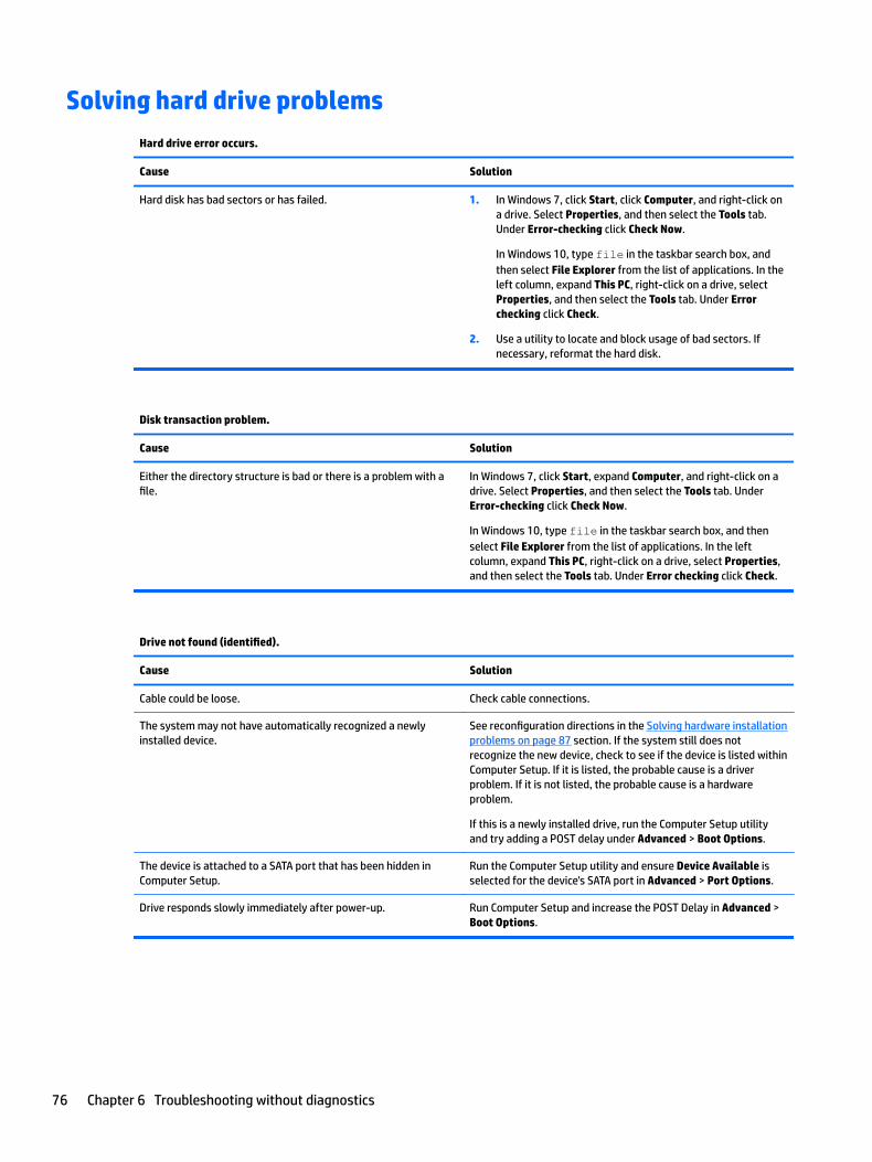
Solving hard drive problemsHard drive error occurs.
Cause Solution
Hard disk has bad sectors or has failed. 1. In Windows 7, click Start, click Computer, and right-click on a drive. Select Properties, and then select the Tools tab. Under Error-checking click Check Now.
In Windows 10, type file in the taskbar search box, and then select File Explorer from the list of applications. In the left column, expand This PC, right-click on a drive, select Properties, and then select the Tools tab. Under Error checking click Check.
2. Use a utility to locate and block usage of bad sectors. If necessary, reformat the hard disk.
Disk transaction problem.
Cause Solution
Either the directory structure is bad or there is a problem with a file.
In Windows 7, click Start, expand Computer, and right-click on a drive. Select Properties, and then select the Tools tab. Under Error-checking click Check Now.
In Windows 10, type file in the taskbar search box, and then select File Explorer from the list of applications. In the left column, expand This PC, right-click on a drive, select Properties, and then select the Tools tab. Under Error checking click Check.
Drive not found (identified).
Cause Solution
Cable could be loose. Check cable connections.
The system may not have automatically recognized a newly installed device.
See reconfiguration directions in the Solving hardware installation problems on page 87 section. If the system still does not recognize the new device, check to see if the device is listed within Computer Setup. If it is listed, the probable cause is a driver problem. If it is not listed, the probable cause is a hardware problem.
If this is a newly installed drive, run the Computer Setup utility and try adding a POST delay under Advanced > Boot Options.
The device is attached to a SATA port that has been hidden in Computer Setup.
Run the Computer Setup utility and ensure Device Available is selected for the device's SATA port in Advanced > Port Options.
Drive responds slowly immediately after power-up. Run Computer Setup and increase the POST Delay in Advanced > Boot Options.
76 Chapter 6 Troubleshooting without diagnostics
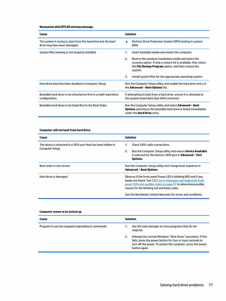
Nonsystem disk/NTLDR missing message.
Cause Solution
The system is trying to start from the hard drive but the hard drive may have been damaged.
▲ Perform Drive Protection System (DPS) testing in system ROM.
System files missing or not properly installed. 1. Insert bootable media and restart the computer.
2. Boot to the windows installation media and select the recovery option. If only a restore kit is available, then select the File Backup Program option, and then restore the system.
3. Install system files for the appropriate operating system.
Hard drive boot has been disabled in Computer Setup. Run the Computer Setup utility and enable the hard drive entry in the Advanced > Boot Options list.
Bootable hard drive is not attached as first in a multi-hard drive configuration.
If attempting to boot from a hard drive, ensure it is attached to the system board dark blue SATA connector.
Bootable hard drive is not listed first in the Boot Order. Run the Computer Setup utility and select Advanced > Boot Options and ensure the bootable hard drive is listed immediately under the Hard Drive entry.
Computer will not boot from hard drive.
Cause Solution
The device is attached to a SATA port that has been hidden in Computer Setup.
1. Check SATA cable connections.
2. Run the Computer Setup utility and ensure Device Available is selected for the device's SATA port in Advanced > Port Options.
Boot order is not correct. Run the Computer Setup utility and change boot sequence in Advanced > Boot Options.
Hard drive is damaged. Observe if the front panel Power LED is blinking RED and if any beeps are heard. See POST error messages and diagnostic front panel LEDs and audible codes on page 97 to determine possible causes for the blinking red and beep codes.
See the Worldwide Limited Warranty for terms and conditions.
Computer seems to be locked up.
Cause Solution
Program in use has stopped responding to commands. 1. Use the task manager to close programs that do not respond.
2. Attempt the normal Windows “Shut Down” procedure. If this fails, press the power button for four or more seconds to turn off the power. To restart the computer, press the power button again.
Solving hard drive problems 77
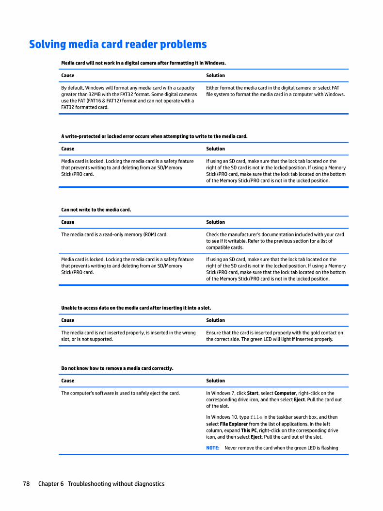
Solving media card reader problemsMedia card will not work in a digital camera after formatting it in Windows.
Cause Solution
By default, Windows will format any media card with a capacity greater than 32MB with the FAT32 format. Some digital cameras use the FAT (FAT16 & FAT12) format and can not operate with a FAT32 formatted card.
Either format the media card in the digital camera or select FAT file system to format the media card in a computer with Windows.
A write-protected or locked error occurs when attempting to write to the media card.
Cause Solution
Media card is locked. Locking the media card is a safety feature that prevents writing to and deleting from an SD/Memory Stick/PRO card.
If using an SD card, make sure that the lock tab located on the right of the SD card is not in the locked position. If using a Memory Stick/PRO card, make sure that the lock tab located on the bottom of the Memory Stick/PRO card is not in the locked position.
Can not write to the media card.
Cause Solution
The media card is a read-only memory (ROM) card. Check the manufacturer’s documentation included with your card to see if it writable. Refer to the previous section for a list of compatible cards.
Media card is locked. Locking the media card is a safety feature that prevents writing to and deleting from an SD/Memory Stick/PRO card.
If using an SD card, make sure that the lock tab located on the right of the SD card is not in the locked position. If using a Memory Stick/PRO card, make sure that the lock tab located on the bottom of the Memory Stick/PRO card is not in the locked position.
Unable to access data on the media card after inserting it into a slot.
Cause Solution
The media card is not inserted properly, is inserted in the wrong slot, or is not supported.
Ensure that the card is inserted properly with the gold contact on the correct side. The green LED will light if inserted properly.
Do not know how to remove a media card correctly.
Cause Solution
The computer’s software is used to safely eject the card. In Windows 7, click Start, select Computer, right-click on the corresponding drive icon, and then select Eject. Pull the card out of the slot.
In Windows 10, type file in the taskbar search box, and then select File Explorer from the list of applications. In the left column, expand This PC, right-click on the corresponding drive icon, and then select Eject. Pull the card out of the slot.
NOTE: Never remove the card when the green LED is flashing
78 Chapter 6 Troubleshooting without diagnostics
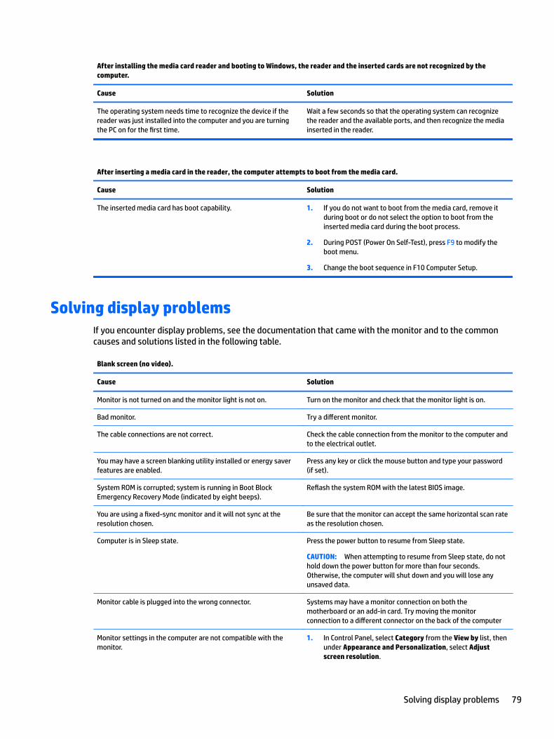
After installing the media card reader and booting to Windows, the reader and the inserted cards are not recognized by the computer.
Cause Solution
The operating system needs time to recognize the device if the reader was just installed into the computer and you are turning the PC on for the first time.
Wait a few seconds so that the operating system can recognize the reader and the available ports, and then recognize the media inserted in the reader.
After inserting a media card in the reader, the computer attempts to boot from the media card.
Cause Solution
The inserted media card has boot capability. 1. If you do not want to boot from the media card, remove it during boot or do not select the option to boot from the inserted media card during the boot process.
2. During POST (Power On Self-Test), press F9 to modify the boot menu.
3. Change the boot sequence in F10 Computer Setup.
Solving display problemsIf you encounter display problems, see the documentation that came with the monitor and to the common causes and solutions listed in the following table.
Blank screen (no video).
Cause Solution
Monitor is not turned on and the monitor light is not on. Turn on the monitor and check that the monitor light is on.
Bad monitor. Try a different monitor.
The cable connections are not correct. Check the cable connection from the monitor to the computer and to the electrical outlet.
You may have a screen blanking utility installed or energy saver features are enabled.
Press any key or click the mouse button and type your password (if set).
System ROM is corrupted; system is running in Boot Block Emergency Recovery Mode (indicated by eight beeps).
Reflash the system ROM with the latest BIOS image.
You are using a fixed-sync monitor and it will not sync at the resolution chosen.
Be sure that the monitor can accept the same horizontal scan rate as the resolution chosen.
Computer is in Sleep state. Press the power button to resume from Sleep state.
CAUTION: When attempting to resume from Sleep state, do not hold down the power button for more than four seconds. Otherwise, the computer will shut down and you will lose any unsaved data.
Monitor cable is plugged into the wrong connector. Systems may have a monitor connection on both the motherboard or an add-in card. Try moving the monitor connection to a different connector on the back of the computer
Monitor settings in the computer are not compatible with the monitor.
1. In Control Panel, select Category from the View by list, then under Appearance and Personalization, select Adjust screen resolution.
Solving display problems 79
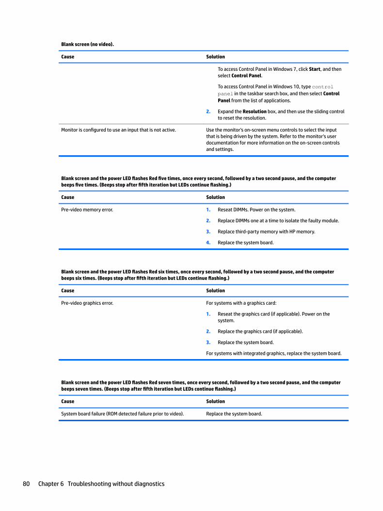
Blank screen (no video).
Cause Solution
To access Control Panel in Windows 7, click Start, and then select Control Panel.
To access Control Panel in Windows 10, type control panel in the taskbar search box, and then select Control Panel from the list of applications.
2. Expand the Resolution box, and then use the sliding control to reset the resolution.
Monitor is configured to use an input that is not active. Use the monitor's on-screen menu controls to select the input that is being driven by the system. Refer to the monitor's user documentation for more information on the on-screen controls and settings.
Blank screen and the power LED flashes Red five times, once every second, followed by a two second pause, and the computer beeps five times. (Beeps stop after fifth iteration but LEDs continue flashing.)
Cause Solution
Pre-video memory error. 1. Reseat DIMMs. Power on the system.
2. Replace DIMMs one at a time to isolate the faulty module.
3. Replace third-party memory with HP memory.
4. Replace the system board.
Blank screen and the power LED flashes Red six times, once every second, followed by a two second pause, and the computer beeps six times. (Beeps stop after fifth iteration but LEDs continue flashing.)
Cause Solution
Pre-video graphics error. For systems with a graphics card:
1. Reseat the graphics card (if applicable). Power on the system.
2. Replace the graphics card (if applicable).
3. Replace the system board.
For systems with integrated graphics, replace the system board.
Blank screen and the power LED flashes Red seven times, once every second, followed by a two second pause, and the computer beeps seven times. (Beeps stop after fifth iteration but LEDs continue flashing.)
Cause Solution
System board failure (ROM detected failure prior to video). Replace the system board.
80 Chapter 6 Troubleshooting without diagnostics
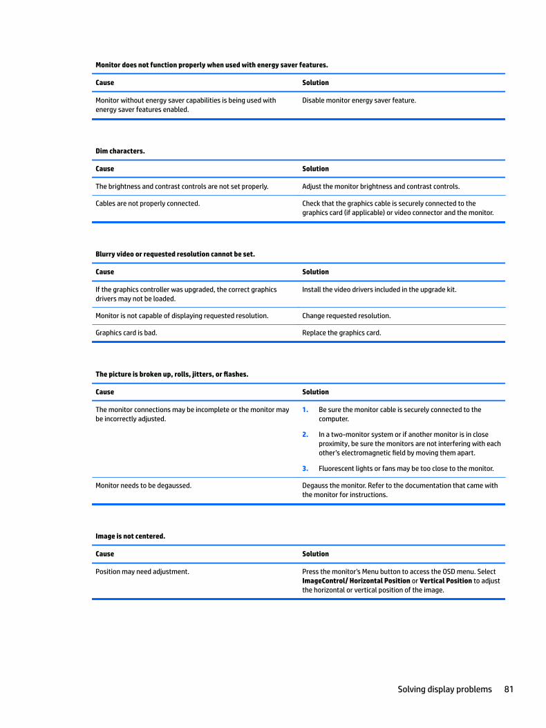
Monitor does not function properly when used with energy saver features.
Cause Solution
Monitor without energy saver capabilities is being used with energy saver features enabled.
Disable monitor energy saver feature.
Dim characters.
Cause Solution
The brightness and contrast controls are not set properly. Adjust the monitor brightness and contrast controls.
Cables are not properly connected. Check that the graphics cable is securely connected to the graphics card (if applicable) or video connector and the monitor.
Blurry video or requested resolution cannot be set.
Cause Solution
If the graphics controller was upgraded, the correct graphics drivers may not be loaded.
Install the video drivers included in the upgrade kit.
Monitor is not capable of displaying requested resolution. Change requested resolution.
Graphics card is bad. Replace the graphics card.
The picture is broken up, rolls, jitters, or flashes.
Cause Solution
The monitor connections may be incomplete or the monitor may be incorrectly adjusted.
1. Be sure the monitor cable is securely connected to the computer.
2. In a two-monitor system or if another monitor is in close proximity, be sure the monitors are not interfering with each other’s electromagnetic field by moving them apart.
3. Fluorescent lights or fans may be too close to the monitor.
Monitor needs to be degaussed. Degauss the monitor. Refer to the documentation that came with the monitor for instructions.
Image is not centered.
Cause Solution
Position may need adjustment. Press the monitor's Menu button to access the OSD menu. Select ImageControl/ Horizontal Position or Vertical Position to adjust the horizontal or vertical position of the image.
Solving display problems 81
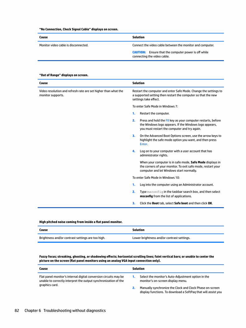
“No Connection, Check Signal Cable” displays on screen.
Cause Solution
Monitor video cable is disconnected. Connect the video cable between the monitor and computer.
CAUTION: Ensure that the computer power is off while connecting the video cable.
“Out of Range” displays on screen.
Cause Solution
Video resolution and refresh rate are set higher than what the monitor supports.
Restart the computer and enter Safe Mode. Change the settings to a supported setting then restart the computer so that the new settings take effect.
To enter Safe Mode in Windows 7:
1. Restart the computer.
2. Press and hold the F8 key as your computer restarts, before the Windows logo appears. If the Windows logo appears, you must restart the computer and try again.
3. On the Advanced Boot Options screen, use the arrow keys to highlight the safe mode option you want, and then press Enter.
4. Log on to your computer with a user account that has administrator rights.
When your computer is in safe mode, Safe Mode displays in the corners of your monitor. To exit safe mode, restart your computer and let Windows start normally.
To enter Safe Mode in Windows 10:
1. Log into the computer using an Administrator account.
2. Type msconfig in the taskbar search box, and then select msconfig from the list of applications.
3. Click the Boot tab, select Safe boot and then click OK.
High pitched noise coming from inside a flat panel monitor.
Cause Solution
Brightness and/or contrast settings are too high. Lower brightness and/or contrast settings.
Fuzzy focus; streaking, ghosting, or shadowing effects; horizontal scrolling lines; faint vertical bars; or unable to center the picture on the screen (flat panel monitors using an analog VGA input connection only).
Cause Solution
Flat panel monitor’s internal digital conversion circuits may be unable to correctly interpret the output synchronization of the graphics card.
1. Select the monitor’s Auto-Adjustment option in the monitor’s on-screen display menu.
2. Manually synchronize the Clock and Clock Phase on-screen display functions. To download a SoftPaq that will assist you
82 Chapter 6 Troubleshooting without diagnostics
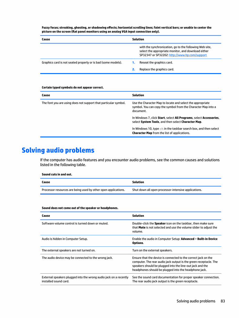
Fuzzy focus; streaking, ghosting, or shadowing effects; horizontal scrolling lines; faint vertical bars; or unable to center the picture on the screen (flat panel monitors using an analog VGA input connection only).
Cause Solution
with the synchronization, go to the following Web site, select the appropriate monitor, and download either SP32347 or SP32202: http://www.hp.com/support
Graphics card is not seated properly or is bad (some models). 1. Reseat the graphics card.
2. Replace the graphics card.
Certain typed symbols do not appear correct.
Cause Solution
The font you are using does not support that particular symbol. Use the Character Map to locate and select the appropriate symbol. You can copy the symbol from the Character Map into a document.
In Windows 7, click Start, select All Programs, select Accessories, select System Tools, and then select Character Map.
In Windows 10, type ch in the taskbar search box, and then select Character Map from the list of applications.
Solving audio problemsIf the computer has audio features and you encounter audio problems, see the common causes and solutions listed in the following table.
Sound cuts in and out.
Cause Solution
Processor resources are being used by other open applications. Shut down all open processor-intensive applications.
Sound does not come out of the speaker or headphones.
Cause Solution
Software volume control is turned down or muted. Double-click the Speaker icon on the taskbar, then make sure that Mute is not selected and use the volume slider to adjust the volume.
Audio is hidden in Computer Setup. Enable the audio in Computer Setup: Advanced > Built-in Device Options.
The external speakers are not turned on. Turn on the external speakers.
The audio device may be connected to the wrong jack. Ensure that the device is connected to the correct jack on the computer. The rear audio jack output is the green receptacle. The speakers should be plugged into the line-out jack and the headphones should be plugged into the headphone jack.
External speakers plugged into the wrong audio jack on a recently installed sound card.
See the sound card documentation for proper speaker connection. The rear audio jack output is the green receptacle.
Solving audio problems 83
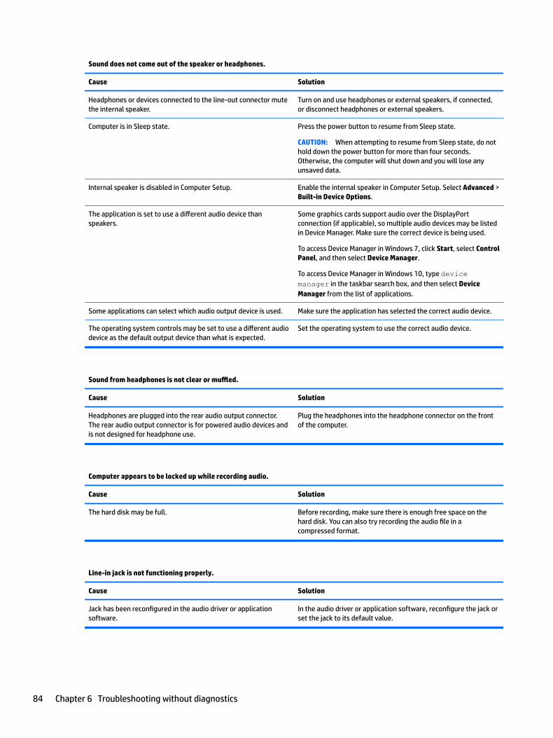
Sound does not come out of the speaker or headphones.
Cause Solution
Headphones or devices connected to the line-out connector mute the internal speaker.
Turn on and use headphones or external speakers, if connected, or disconnect headphones or external speakers.
Computer is in Sleep state. Press the power button to resume from Sleep state.
CAUTION: When attempting to resume from Sleep state, do not hold down the power button for more than four seconds. Otherwise, the computer will shut down and you will lose any unsaved data.
Internal speaker is disabled in Computer Setup. Enable the internal speaker in Computer Setup. Select Advanced > Built-in Device Options.
The application is set to use a different audio device than speakers.
Some graphics cards support audio over the DisplayPort connection (if applicable), so multiple audio devices may be listed in Device Manager. Make sure the correct device is being used.
To access Device Manager in Windows 7, click Start, select Control Panel, and then select Device Manager.
To access Device Manager in Windows 10, type device manager in the taskbar search box, and then select Device Manager from the list of applications.
Some applications can select which audio output device is used. Make sure the application has selected the correct audio device.
The operating system controls may be set to use a different audio device as the default output device than what is expected.
Set the operating system to use the correct audio device.
Sound from headphones is not clear or muffled.
Cause Solution
Headphones are plugged into the rear audio output connector. The rear audio output connector is for powered audio devices and is not designed for headphone use.
Plug the headphones into the headphone connector on the front of the computer.
Computer appears to be locked up while recording audio.
Cause Solution
The hard disk may be full. Before recording, make sure there is enough free space on the hard disk. You can also try recording the audio file in a compressed format.
Line-in jack is not functioning properly.
Cause Solution
Jack has been reconfigured in the audio driver or application software.
In the audio driver or application software, reconfigure the jack or set the jack to its default value.
84 Chapter 6 Troubleshooting without diagnostics
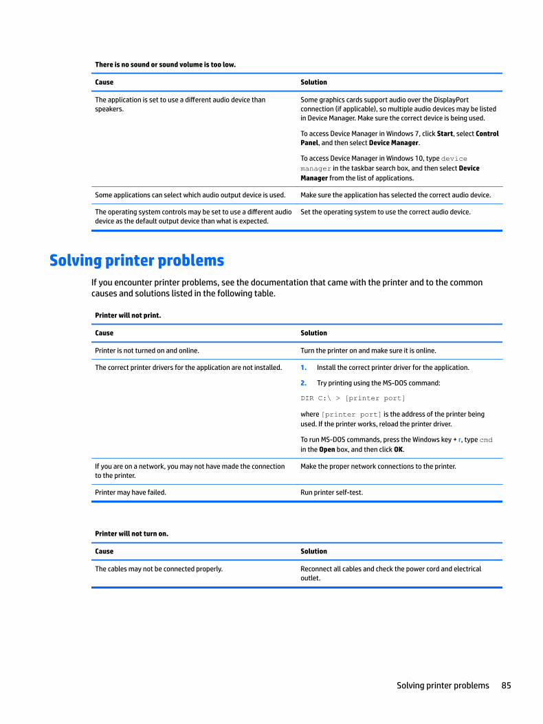
There is no sound or sound volume is too low.
Cause Solution
The application is set to use a different audio device than speakers.
Some graphics cards support audio over the DisplayPort connection (if applicable), so multiple audio devices may be listed in Device Manager. Make sure the correct device is being used.
To access Device Manager in Windows 7, click Start, select Control Panel, and then select Device Manager.
To access Device Manager in Windows 10, type device manager in the taskbar search box, and then select Device Manager from the list of applications.
Some applications can select which audio output device is used. Make sure the application has selected the correct audio device.
The operating system controls may be set to use a different audio device as the default output device than what is expected.
Set the operating system to use the correct audio device.
Solving printer problemsIf you encounter printer problems, see the documentation that came with the printer and to the common causes and solutions listed in the following table.
Printer will not print.
Cause Solution
Printer is not turned on and online. Turn the printer on and make sure it is online.
The correct printer drivers for the application are not installed. 1. Install the correct printer driver for the application.
2. Try printing using the MS-DOS command:
DIR C:\ > [printer port]
where [printer port] is the address of the printer being used. If the printer works, reload the printer driver.
To run MS-DOS commands, press the Windows key + r, type cmd in the Open box, and then click OK.
If you are on a network, you may not have made the connection to the printer.
Make the proper network connections to the printer.
Printer may have failed. Run printer self-test.
Printer will not turn on.
Cause Solution
The cables may not be connected properly. Reconnect all cables and check the power cord and electrical outlet.
Solving printer problems 85
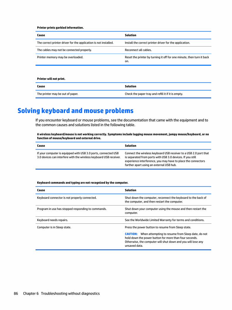
Printer prints garbled information.
Cause Solution
The correct printer driver for the application is not installed. Install the correct printer driver for the application.
The cables may not be connected properly. Reconnect all cables.
Printer memory may be overloaded. Reset the printer by turning it off for one minute, then turn it back on.
Printer will not print.
Cause Solution
The printer may be out of paper. Check the paper tray and refill it if it is empty.
Solving keyboard and mouse problemsIf you encounter keyboard or mouse problems, see the documentation that came with the equipment and to the common causes and solutions listed in the following table.
A wireless keyboard/mouse is not working correctly. Symptoms include lagging mouse movement, jumpy mouse/keyboard, or no function of mouse/keyboard and external drive.
Cause Solution
If your computer is equipped with USB 3.0 ports, connected USB 3.0 devices can interfere with the wireless keyboard USB receiver.
Connect the wireless keyboard USB receiver to a USB 2.0 port that is separated from ports with USB 3.0 devices. If you still experience interference, you may have to place the connectors farther apart using an external USB hub.
Keyboard commands and typing are not recognized by the computer.
Cause Solution
Keyboard connector is not properly connected. Shut down the computer, reconnect the keyboard to the back of the computer, and then restart the computer.
Program in use has stopped responding to commands. Shut down your computer using the mouse and then restart the computer.
Keyboard needs repairs. See the Worldwide Limited Warranty for terms and conditions.
Computer is in Sleep state. Press the power button to resume from Sleep state.
CAUTION: When attempting to resume from Sleep date, do not hold down the power button for more than four seconds. Otherwise, the computer will shut down and you will lose any unsaved data.
86 Chapter 6 Troubleshooting without diagnostics
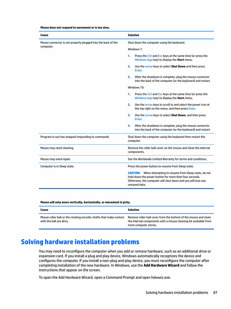
Mouse does not respond to movement or is too slow.
Cause Solution
Mouse connector is not properly plugged into the back of the computer.
Shut down the computer using the keyboard.
Windows 7:
1. Press the Ctrl and Esc keys at the same time (or press the Windows logo key) to display the Start menu.
2. Use the arrow keys to select Shut Down and then press Enter.
3. After the shutdown is complete, plug the mouse connector into the back of the computer (or the keyboard) and restart.
Windows 10:
1. Press the Ctrl and Esc keys at the same time (or press the Windows logo key) to display the Start menu.
2. Use the arrow keys to scroll to and select the power icon at the top right on the menu, and then press Enter.
3. Use the arrow keys to select Shut Down, and then press Enter.
4. After the shutdown is complete, plug the mouse connector into the back of the computer (or the keyboard) and restart.
Program in use has stopped responding to commands. Shut down the computer using the keyboard then restart the computer.
Mouse may need cleaning. Remove the roller ball cover on the mouse and clean the internal components.
Mouse may need repair. See the Worldwide Limited Warranty for terms and conditions.
Computer is in Sleep state. Press the power button to resume from Sleep state.
CAUTION: When attempting to resume from Sleep state, do not hold down the power button for more than four seconds. Otherwise, the computer will shut down and you will lose any unsaved data.
Mouse will only move vertically, horizontally, or movement is jerky.
Cause Solution
Mouse roller ball or the rotating encoder shafts that make contact with the ball are dirty.
Remove roller ball cover from the bottom of the mouse and clean the internal components with a mouse cleaning kit available from most computer stores.
Solving hardware installation problemsYou may need to reconfigure the computer when you add or remove hardware, such as an additional drive or expansion card. If you install a plug and play device, Windows automatically recognizes the device and configures the computer. If you install a non-plug and play device, you must reconfigure the computer after completing installation of the new hardware. In Windows, use the Add Hardware Wizard and follow the instructions that appear on the screen.
To open the Add Hardware Wizard, open a Command Prompt and open hdwwiz.exe.
Solving hardware installation problems 87
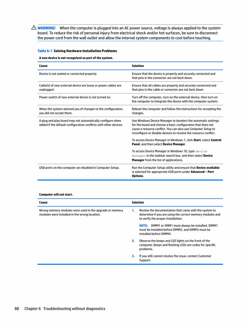
WARNING! When the computer is plugged into an AC power source, voltage is always applied to the system board. To reduce the risk of personal injury from electrical shock and/or hot surfaces, be sure to disconnect the power cord from the wall outlet and allow the internal system components to cool before touching.
Table 6-1 Solving Hardware Installation Problems
A new device is not recognized as part of the system.
Cause Solution
Device is not seated or connected properly. Ensure that the device is properly and securely connected and that pins in the connector are not bent down.
Cable(s) of new external device are loose or power cables are unplugged.
Ensure that all cables are properly and securely connected and that pins in the cable or connector are not bent down.
Power switch of new external device is not turned on. Turn off the computer, turn on the external device, then turn on the computer to integrate the device with the computer system.
When the system advised you of changes to the configuration, you did not accept them.
Reboot the computer and follow the instructions for accepting the changes.
A plug and play board may not automatically configure when added if the default configuration conflicts with other devices.
Use Windows Device Manager to deselect the automatic settings for the board and choose a basic configuration that does not cause a resource conflict. You can also use Computer Setup to reconfigure or disable devices to resolve the resource conflict.
To access Device Manager in Windows 7, click Start, select Control Panel, and then select Device Manager.
To access Device Manager in Windows 10, type device manager in the taskbar search box, and then select Device Manager from the list of applications.
USB ports on the computer are disabled in Computer Setup. Run the Computer Setup utility and ensure that Device available is selected for appropriate USB ports under Advanced > Port Options.
Computer will not start.
Cause Solution
Wrong memory modules were used in the upgrade or memory modules were installed in the wrong location.
1. Review the documentation that came with the system to determine if you are using the correct memory modules and to verify the proper installation.
NOTE: DIMM1 or XMM1 must always be installed. DIMM1 must be installed before DIMM2, and DIMM3 must be installed before DIMM4.
2. Observe the beeps and LED lights on the front of the computer. Beeps and flashing LEDs are codes for specific problems.
3. If you still cannot resolve the issue, contact Customer Support.
88 Chapter 6 Troubleshooting without diagnostics
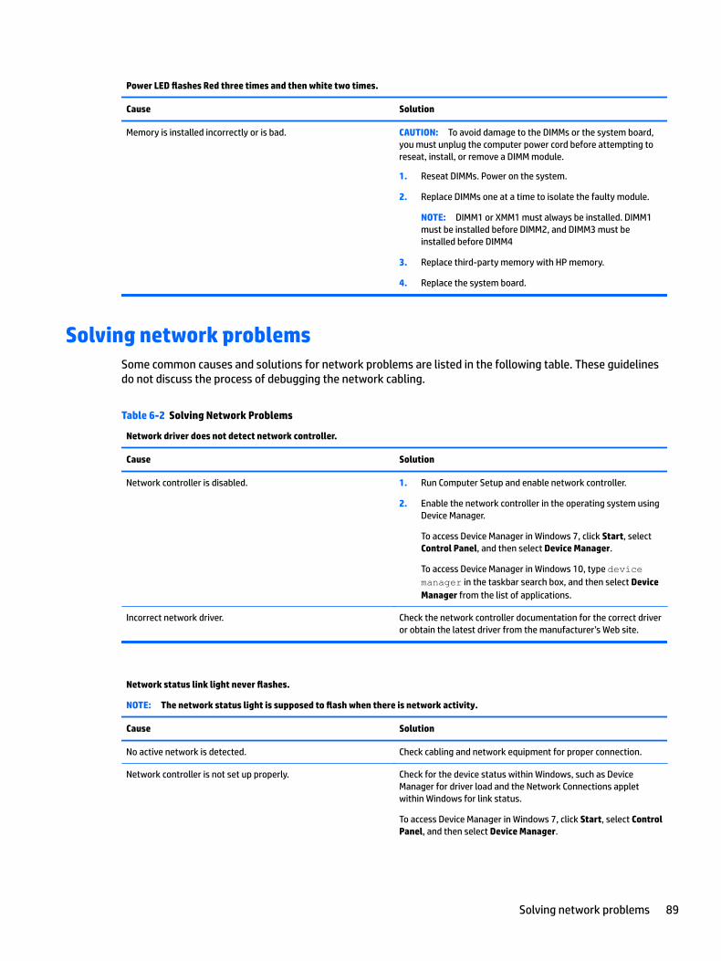
Power LED flashes Red three times and then white two times.
Cause Solution
Memory is installed incorrectly or is bad. CAUTION: To avoid damage to the DIMMs or the system board, you must unplug the computer power cord before attempting to reseat, install, or remove a DIMM module.
1. Reseat DIMMs. Power on the system.
2. Replace DIMMs one at a time to isolate the faulty module.
NOTE: DIMM1 or XMM1 must always be installed. DIMM1 must be installed before DIMM2, and DIMM3 must be installed before DIMM4
3. Replace third-party memory with HP memory.
4. Replace the system board.
Solving network problemsSome common causes and solutions for network problems are listed in the following table. These guidelines do not discuss the process of debugging the network cabling.
Table 6-2 Solving Network Problems
Network driver does not detect network controller.
Cause Solution
Network controller is disabled. 1. Run Computer Setup and enable network controller.
2. Enable the network controller in the operating system using Device Manager.
To access Device Manager in Windows 7, click Start, select Control Panel, and then select Device Manager.
To access Device Manager in Windows 10, type device manager in the taskbar search box, and then select Device Manager from the list of applications.
Incorrect network driver. Check the network controller documentation for the correct driver or obtain the latest driver from the manufacturer’s Web site.
Network status link light never flashes.
NOTE: The network status light is supposed to flash when there is network activity.
Cause Solution
No active network is detected. Check cabling and network equipment for proper connection.
Network controller is not set up properly. Check for the device status within Windows, such as Device Manager for driver load and the Network Connections applet within Windows for link status.
To access Device Manager in Windows 7, click Start, select Control Panel, and then select Device Manager.
Solving network problems 89
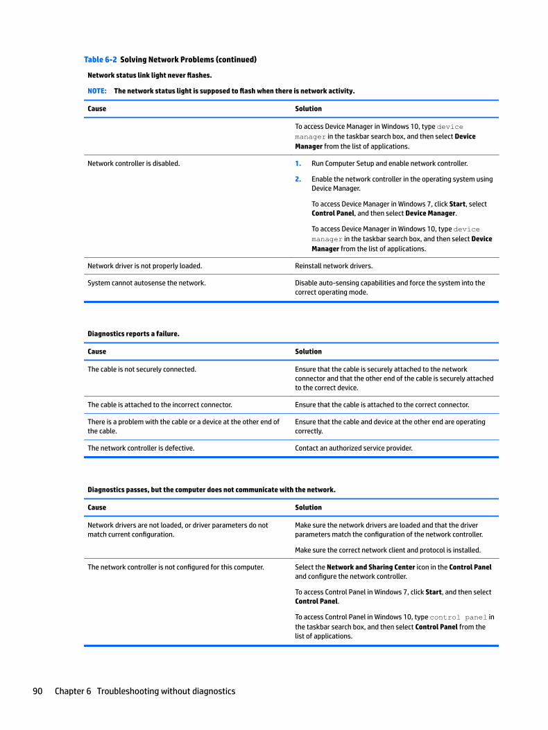
Table 6-2 Solving Network Problems (continued)
Network status link light never flashes.
NOTE: The network status light is supposed to flash when there is network activity.
Cause Solution
To access Device Manager in Windows 10, type device manager in the taskbar search box, and then select Device Manager from the list of applications.
Network controller is disabled. 1. Run Computer Setup and enable network controller.
2. Enable the network controller in the operating system using Device Manager.
To access Device Manager in Windows 7, click Start, select Control Panel, and then select Device Manager.
To access Device Manager in Windows 10, type device manager in the taskbar search box, and then select Device Manager from the list of applications.
Network driver is not properly loaded. Reinstall network drivers.
System cannot autosense the network. Disable auto-sensing capabilities and force the system into the correct operating mode.
Diagnostics reports a failure.
Cause Solution
The cable is not securely connected. Ensure that the cable is securely attached to the network connector and that the other end of the cable is securely attached to the correct device.
The cable is attached to the incorrect connector. Ensure that the cable is attached to the correct connector.
There is a problem with the cable or a device at the other end of the cable.
Ensure that the cable and device at the other end are operating correctly.
The network controller is defective. Contact an authorized service provider.
Diagnostics passes, but the computer does not communicate with the network.
Cause Solution
Network drivers are not loaded, or driver parameters do not match current configuration.
Make sure the network drivers are loaded and that the driver parameters match the configuration of the network controller.
Make sure the correct network client and protocol is installed.
The network controller is not configured for this computer. Select the Network and Sharing Center icon in the Control Panel and configure the network controller.
To access Control Panel in Windows 7, click Start, and then select Control Panel.
To access Control Panel in Windows 10, type control panel in the taskbar search box, and then select Control Panel from the list of applications.
90 Chapter 6 Troubleshooting without diagnostics
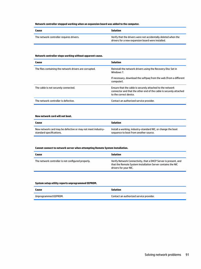
Network controller stopped working when an expansion board was added to the computer.
Cause Solution
The network controller requires drivers. Verify that the drivers were not accidentally deleted when the drivers for a new expansion board were installed.
Network controller stops working without apparent cause.
Cause Solution
The files containing the network drivers are corrupted. Reinstall the network drivers using the Recovery Disc Set in Windows 7.
If necessary, download the softpaq from the web (from a different computer).
The cable is not securely connected. Ensure that the cable is securely attached to the network connector and that the other end of the cable is securely attached to the correct device.
The network controller is defective. Contact an authorized service provider.
New network card will not boot.
Cause Solution
New network card may be defective or may not meet industry-standard specifications.
Install a working, industry-standard NIC, or change the boot sequence to boot from another source.
Cannot connect to network server when attempting Remote System Installation.
Cause Solution
The network controller is not configured properly. Verify Network Connectivity, that a DHCP Server is present, and that the Remote System Installation Server contains the NIC drivers for your NIC.
System setup utility reports unprogrammed EEPROM.
Cause Solution
Unprogrammed EEPROM. Contact an authorized service provider.
Solving network problems 91
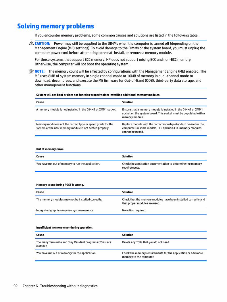
Solving memory problemsIf you encounter memory problems, some common causes and solutions are listed in the following table.
CAUTION: Power may still be supplied to the DIMMs when the computer is turned off (depending on the Management Engine (ME) settings). To avoid damage to the DIMMs or the system board, you must unplug the computer power cord before attempting to reseat, install, or remove a memory module.
For those systems that support ECC memory, HP does not support mixing ECC and non-ECC memory. Otherwise, the computer will not boot the operating system.
NOTE: The memory count will be affected by configurations with the Management Engine (ME) enabled. The ME uses 8MB of system memory in single channel mode or 16MB of memory in dual-channel mode to download, decompress, and execute the ME firmware for Out-of-Band (OOB), third-party data storage, and other management functions.
System will not boot or does not function properly after installing additional memory modules.
Cause Solution
A memory module is not installed in the DIMM1 or XMM1 socket. Ensure that a memory module is installed in the DIMM1 or XMM1 socket on the system board. This socket must be populated with a memory module.
Memory module is not the correct type or speed grade for the system or the new memory module is not seated properly.
Replace module with the correct industry-standard device for the computer. On some models, ECC and non-ECC memory modules cannot be mixed.
Out of memory error.
Cause Solution
You have run out of memory to run the application. Check the application documentation to determine the memory requirements.
Memory count during POST is wrong.
Cause Solution
The memory modules may not be installed correctly. Check that the memory modules have been installed correctly and that proper modules are used.
Integrated graphics may use system memory. No action required.
Insufficient memory error during operation.
Cause Solution
Too many Terminate and Stay Resident programs (TSRs) are installed.
Delete any TSRs that you do not need.
You have run out of memory for the application. Check the memory requirements for the application or add more memory to the computer.
92 Chapter 6 Troubleshooting without diagnostics
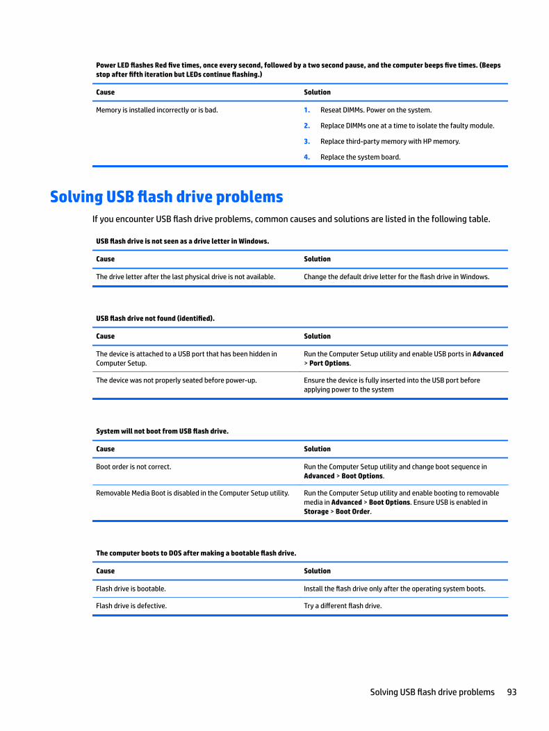
Power LED flashes Red five times, once every second, followed by a two second pause, and the computer beeps five times. (Beeps stop after fifth iteration but LEDs continue flashing.)
Cause Solution
Memory is installed incorrectly or is bad. 1. Reseat DIMMs. Power on the system.
2. Replace DIMMs one at a time to isolate the faulty module.
3. Replace third-party memory with HP memory.
4. Replace the system board.
Solving USB flash drive problemsIf you encounter USB flash drive problems, common causes and solutions are listed in the following table.
USB flash drive is not seen as a drive letter in Windows.
Cause Solution
The drive letter after the last physical drive is not available. Change the default drive letter for the flash drive in Windows.
USB flash drive not found (identified).
Cause Solution
The device is attached to a USB port that has been hidden in Computer Setup.
Run the Computer Setup utility and enable USB ports in Advanced > Port Options.
The device was not properly seated before power-up. Ensure the device is fully inserted into the USB port before applying power to the system
System will not boot from USB flash drive.
Cause Solution
Boot order is not correct. Run the Computer Setup utility and change boot sequence in Advanced > Boot Options.
Removable Media Boot is disabled in the Computer Setup utility. Run the Computer Setup utility and enable booting to removable media in Advanced > Boot Options. Ensure USB is enabled in Storage > Boot Order.
The computer boots to DOS after making a bootable flash drive.
Cause Solution
Flash drive is bootable. Install the flash drive only after the operating system boots.
Flash drive is defective. Try a different flash drive.
Solving USB flash drive problems 93
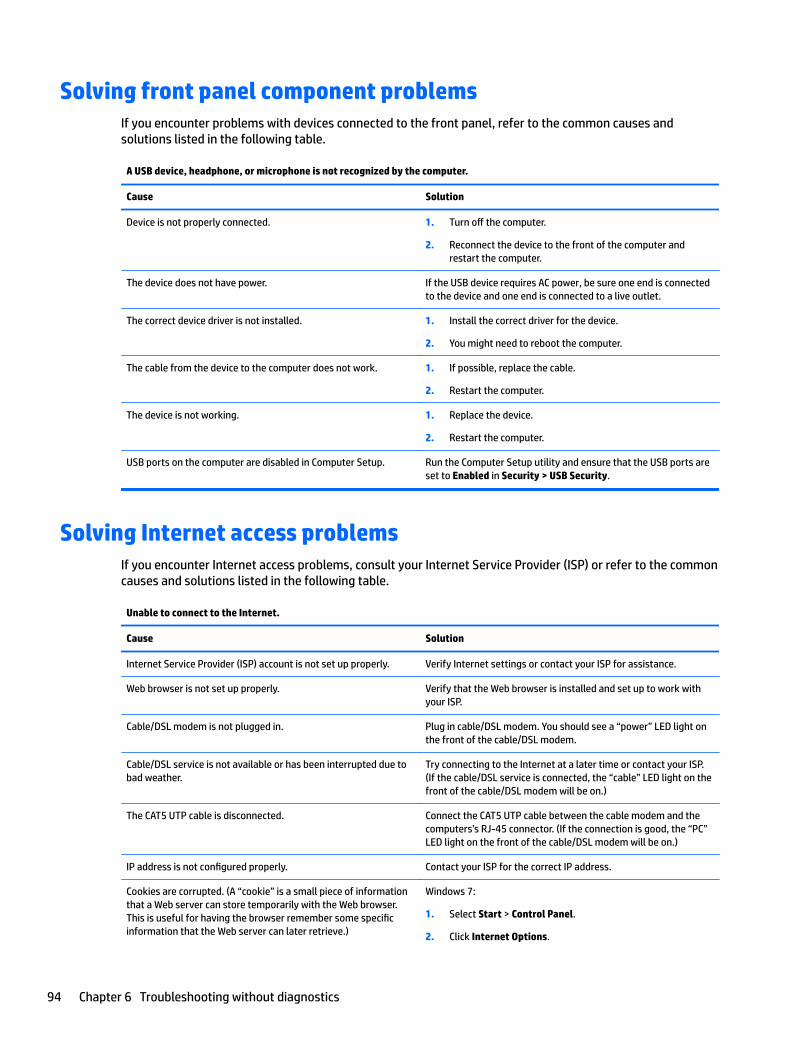
Solving front panel component problemsIf you encounter problems with devices connected to the front panel, refer to the common causes and solutions listed in the following table.
A USB device, headphone, or microphone is not recognized by the computer.
Cause Solution
Device is not properly connected. 1. Turn off the computer.
2. Reconnect the device to the front of the computer and restart the computer.
The device does not have power. If the USB device requires AC power, be sure one end is connected to the device and one end is connected to a live outlet.
The correct device driver is not installed. 1. Install the correct driver for the device.
2. You might need to reboot the computer.
The cable from the device to the computer does not work. 1. If possible, replace the cable.
2. Restart the computer.
The device is not working. 1. Replace the device.
2. Restart the computer.
USB ports on the computer are disabled in Computer Setup. Run the Computer Setup utility and ensure that the USB ports are set to Enabled in Security > USB Security.
Solving Internet access problemsIf you encounter Internet access problems, consult your Internet Service Provider (ISP) or refer to the common causes and solutions listed in the following table.
Unable to connect to the Internet.
Cause Solution
Internet Service Provider (ISP) account is not set up properly. Verify Internet settings or contact your ISP for assistance.
Web browser is not set up properly. Verify that the Web browser is installed and set up to work with your ISP.
Cable/DSL modem is not plugged in. Plug in cable/DSL modem. You should see a “power” LED light on the front of the cable/DSL modem.
Cable/DSL service is not available or has been interrupted due to bad weather.
Try connecting to the Internet at a later time or contact your ISP. (If the cable/DSL service is connected, the “cable” LED light on the front of the cable/DSL modem will be on.)
The CAT5 UTP cable is disconnected. Connect the CAT5 UTP cable between the cable modem and the computers’s RJ-45 connector. (If the connection is good, the “PC” LED light on the front of the cable/DSL modem will be on.)
IP address is not configured properly. Contact your ISP for the correct IP address.
Cookies are corrupted. (A “cookie” is a small piece of information that a Web server can store temporarily with the Web browser. This is useful for having the browser remember some specific information that the Web server can later retrieve.)
Windows 7:
1. Select Start > Control Panel.
2. Click Internet Options.
94 Chapter 6 Troubleshooting without diagnostics
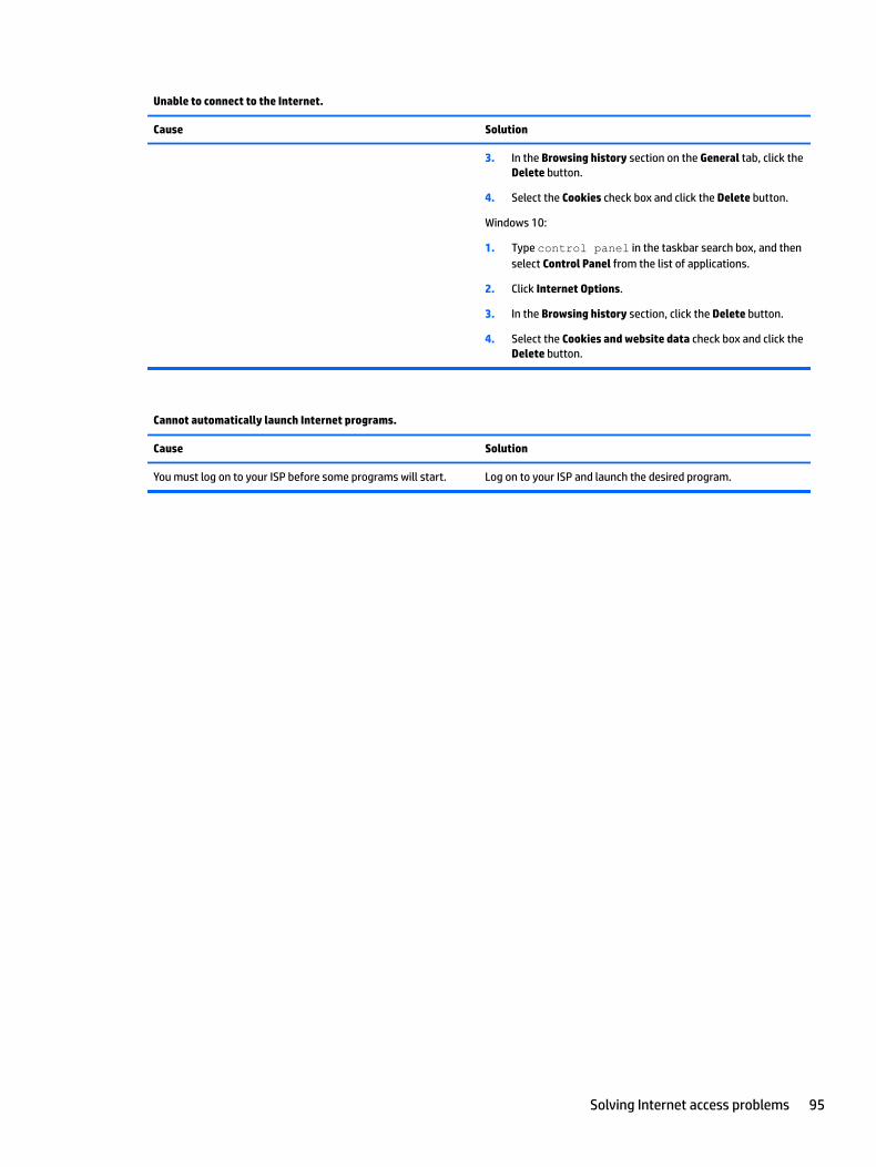
Unable to connect to the Internet.
Cause Solution
3. In the Browsing history section on the General tab, click the Delete button.
4. Select the Cookies check box and click the Delete button.
Windows 10:
1. Type control panel in the taskbar search box, and then select Control Panel from the list of applications.
2. Click Internet Options.
3. In the Browsing history section, click the Delete button.
4. Select the Cookies and website data check box and click the Delete button.
Cannot automatically launch Internet programs.
Cause Solution
You must log on to your ISP before some programs will start. Log on to your ISP and launch the desired program.
Solving Internet access problems 95
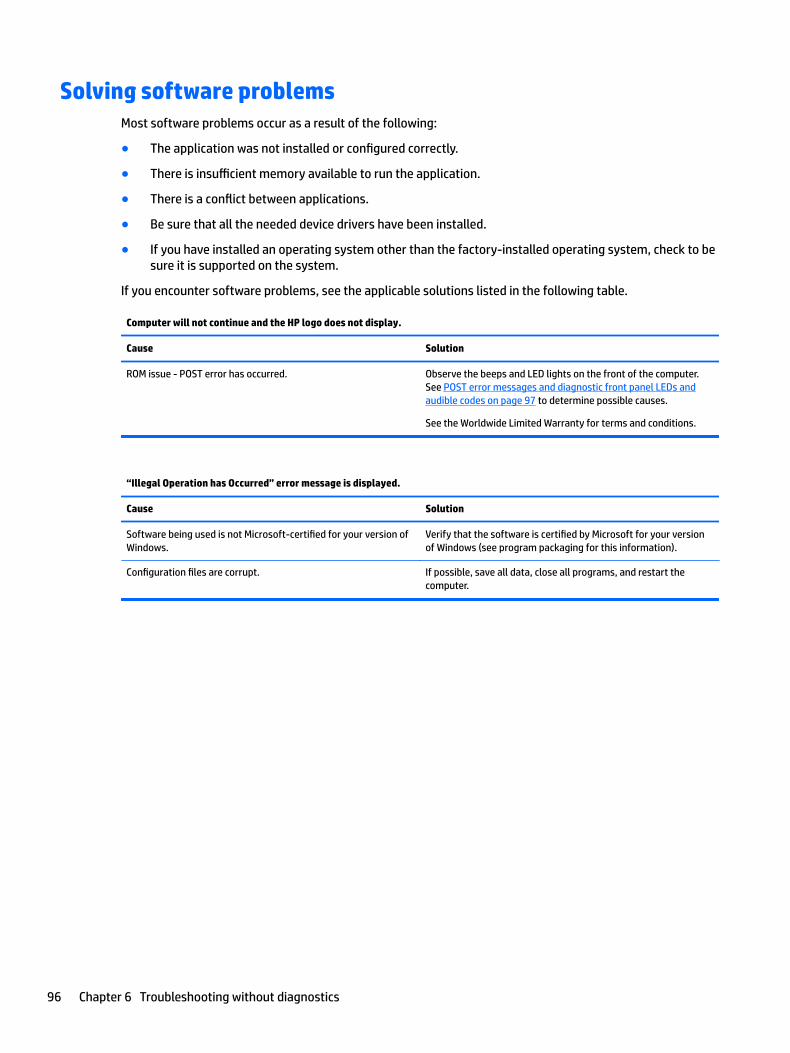
Solving software problemsMost software problems occur as a result of the following:
● The application was not installed or configured correctly.
● There is insufficient memory available to run the application.
● There is a conflict between applications.
● Be sure that all the needed device drivers have been installed.
● If you have installed an operating system other than the factory-installed operating system, check to be sure it is supported on the system.
If you encounter software problems, see the applicable solutions listed in the following table.
Computer will not continue and the HP logo does not display.
Cause Solution
ROM issue - POST error has occurred. Observe the beeps and LED lights on the front of the computer. See POST error messages and diagnostic front panel LEDs and audible codes on page 97 to determine possible causes.
See the Worldwide Limited Warranty for terms and conditions.
“Illegal Operation has Occurred” error message is displayed.
Cause Solution
Software being used is not Microsoft-certified for your version of Windows.
Verify that the software is certified by Microsoft for your version of Windows (see program packaging for this information).
Configuration files are corrupt. If possible, save all data, close all programs, and restart the computer.
96 Chapter 6 Troubleshooting without diagnostics
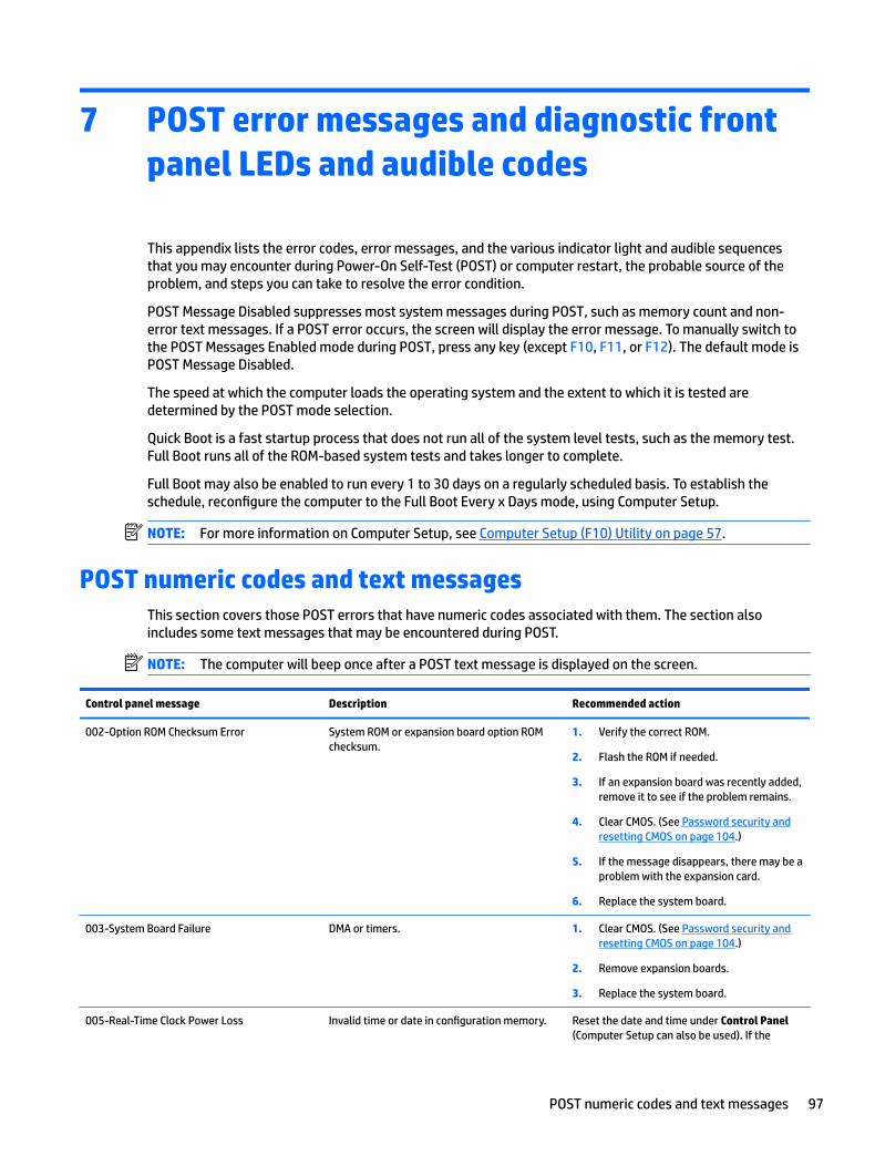
7 POST error messages and diagnostic front panel LEDs and audible codes
This appendix lists the error codes, error messages, and the various indicator light and audible sequences that you may encounter during Power-On Self-Test (POST) or computer restart, the probable source of the problem, and steps you can take to resolve the error condition.
POST Message Disabled suppresses most system messages during POST, such as memory count and non-error text messages. If a POST error occurs, the screen will display the error message. To manually switch to the POST Messages Enabled mode during POST, press any key (except F10, F11, or F12). The default mode is POST Message Disabled.
The speed at which the computer loads the operating system and the extent to which it is tested are determined by the POST mode selection.
Quick Boot is a fast startup process that does not run all of the system level tests, such as the memory test. Full Boot runs all of the ROM-based system tests and takes longer to complete.
Full Boot may also be enabled to run every 1 to 30 days on a regularly scheduled basis. To establish the schedule, reconfigure the computer to the Full Boot Every x Days mode, using Computer Setup.
NOTE: For more information on Computer Setup, see Computer Setup (F10) Utility on page 57.
POST numeric codes and text messagesThis section covers those POST errors that have numeric codes associated with them. The section also includes some text messages that may be encountered during POST.
NOTE: The computer will beep once after a POST text message is displayed on the screen.
Control panel message Description Recommended action
002-Option ROM Checksum Error System ROM or expansion board option ROM checksum.
1. Verify the correct ROM.
2. Flash the ROM if needed.
3. If an expansion board was recently added, remove it to see if the problem remains.
4. Clear CMOS. (See Password security and resetting CMOS on page 104.)
5. If the message disappears, there may be a problem with the expansion card.
6. Replace the system board.
003-System Board Failure DMA or timers. 1. Clear CMOS. (See Password security and resetting CMOS on page 104.)
2. Remove expansion boards.
3. Replace the system board.
005-Real-Time Clock Power Loss Invalid time or date in configuration memory. Reset the date and time under Control Panel (Computer Setup can also be used). If the
POST numeric codes and text messages 97
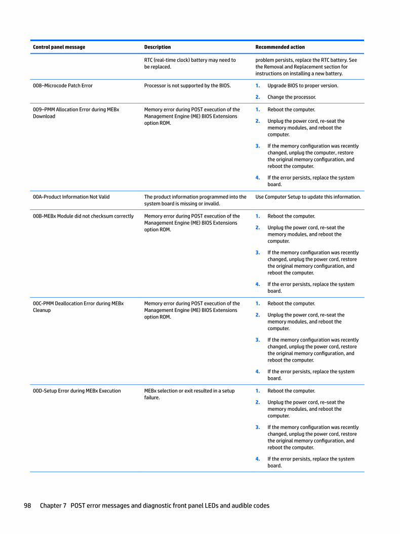
Control panel message Description Recommended action
RTC (real-time clock) battery may need to be replaced.
problem persists, replace the RTC battery. See the Removal and Replacement section for instructions on installing a new battery.
008–Microcode Patch Error Processor is not supported by the BIOS. 1. Upgrade BIOS to proper version.
2. Change the processor.
009–PMM Allocation Error during MEBx Download
Memory error during POST execution of the Management Engine (ME) BIOS Extensions option ROM.
1. Reboot the computer.
2. Unplug the power cord, re-seat the memory modules, and reboot the computer.
3. If the memory configuration was recently changed, unplug the computer, restore the original memory configuration, and reboot the computer.
4. If the error persists, replace the system board.
00A-Product Information Not Valid The product information programmed into the system board is missing or invalid.
Use Computer Setup to update this information.
00B-MEBx Module did not checksum correctly Memory error during POST execution of the Management Engine (ME) BIOS Extensions option ROM.
1. Reboot the computer.
2. Unplug the power cord, re-seat the memory modules, and reboot the computer.
3. If the memory configuration was recently changed, unplug the power cord, restore the original memory configuration, and reboot the computer.
4. If the error persists, replace the system board.
00C-PMM Deallocation Error during MEBx Cleanup
Memory error during POST execution of the Management Engine (ME) BIOS Extensions option ROM.
1. Reboot the computer.
2. Unplug the power cord, re-seat the memory modules, and reboot the computer.
3. If the memory configuration was recently changed, unplug the power cord, restore the original memory configuration, and reboot the computer.
4. If the error persists, replace the system board.
00D-Setup Error during MEBx Execution MEBx selection or exit resulted in a setup failure.
1. Reboot the computer.
2. Unplug the power cord, re-seat the memory modules, and reboot the computer.
3. If the memory configuration was recently changed, unplug the power cord, restore the original memory configuration, and reboot the computer.
4. If the error persists, replace the system board.
98 Chapter 7 POST error messages and diagnostic front panel LEDs and audible codes
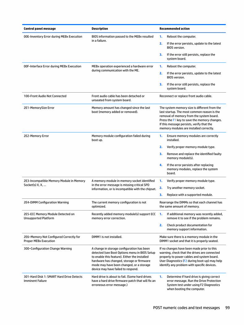
Control panel message Description Recommended action
00E-Inventory Error during MEBx Execution BIOS information passed to the MEBx resulted in a failure.
1. Reboot the computer.
2. If the error persists, update to the latest BIOS version.
3. If the error still persists, replace the system board.
00F-Interface Error during MEBx Execution MEBx operation experienced a hardware error during communication with the ME.
1. Reboot the computer.
2. If the error persists, update to the latest BIOS version.
3. If the error still persists, replace the system board.
100-Front Audio Not Connected Front audio cable has been detached or unseated from system board.
Reconnect or replace front audio cable.
2E1-MemorySize Error Memory amount has changed since the last boot (memory added or removed).
The system memory size is different from the last startup. The most common reason is the removal of memory from the system board. Press the F1 key to save the memory changes. If this message persists, verify that the memory modules are installed correctly.
2E2-Memory Error Memory module configuration failed during boot up.
1. Ensure memory modules are correctly installed.
2. Verify proper memory module type.
3. Remove and replace the identified faulty memory module(s).
4. If the error persists after replacing memory modules, replace the system board.
2E3-Incompatible Memory Module in Memory Socket(s) X, X, ...
A memory module in memory socket identified in the error message is missing critical SPD information, or is incompatible with the chipset.
1. Verify proper memory module type.
2. Try another memory socket.
3. Replace with a supported module.
2E4-DIMM Configuration Warning The current memory configuration is not optimized.
Rearrange the DIMMs so that each channel has the same amount of memory.
2E5-ECC Memory Module Detected on Unsupported Platform
Recently added memory module(s) support ECC memory error correction.
1. If additional memory was recently added, remove it to see if the problem remains.
2. Check product documentation for memory support information.
2E6–Memory Not Configured Correctly for Proper MEBx Execution
DIMM1 is not installed. Make sure there is a memory module in the DIMM1 socket and that it is properly seated.
300–Configuration Change Warning A change in storage configuration has been detected (see Boot Options menu in BIOS Setup to enable this feature). Either the installed hardware has changed, storage or firmware mode may have been changed, or a storage device may have failed to respond.
If no changes have been made prior to this warning, check that the drives are connected properly to power cables and system board. User Diagnostics (F2 during boot-up) may help identify any problem with specific devices.
301-Hard Disk 1: SMART Hard Drive Detects Imminent Failure
Hard drive is about to fail. (Some hard drives have a hard drive firmware patch that will fix an erroneous error message.)
1. Determine if hard drive is giving correct error message. Run the Drive Protection System test under using F2 Diagnostics when booting the computer.
POST numeric codes and text messages 99
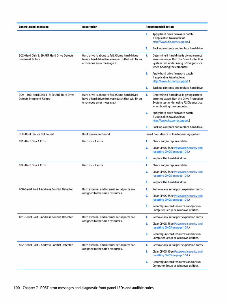
Control panel message Description Recommended action
2. Apply hard drive firmware patch if applicable. (Available at http://www.hp.com/support.)
3. Back up contents and replace hard drive.
302-Hard Disk 2: SMART Hard Drive Detects Imminent Failure
Hard drive is about to fail. (Some hard drives have a hard drive firmware patch that will fix an erroneous error message.)
1. Determine if hard drive is giving correct error message. Run the Drive Protection System test under using F2 Diagnostics when booting the computer.
2. Apply hard drive firmware patch if applicable. (Available at http://www.hp.com/support.)
3. Back up contents and replace hard drive.
309 – 30C: Hard Disk 3–6: SMART Hard Drive Detects Imminent Failure
Hard drive is about to fail. (Some hard drives have a hard drive firmware patch that will fix an erroneous error message.)
1. Determine if hard drive is giving correct error message. Run the Drive Protection System test under using F2 Diagnostics when booting the computer.
2. Apply hard drive firmware patch if applicable. (Available at http://www.hp.com/support.)
3. Back up contents and replace hard drive.
3F0–Boot Device Not Found Boot device not found. Insert boot device or load operating system.
3F1–Hard Disk 1 Error Hard disk 1 error. 1. Check and/or replace cables.
2. Clear CMOS. (See Password security and resetting CMOS on page 104.)
3. Replace the hard disk drive.
3F2–Hard Disk 2 Error Hard disk 2 error. 1. Check and/or replace cables.
2. Clear CMOS. (See Password security and resetting CMOS on page 104.)
3. Replace the hard disk drive.
400-Serial Port A Address Conflict Detected Both external and internal serial ports are assigned to the same resources.
1. Remove any serial port expansion cards.
2. Clear CMOS. (See Password security and resetting CMOS on page 104.)
3. Reconfigure card resources and/or run Computer Setup or Windows utilities.
401-Serial Port B Address Conflict Detected Both external and internal serial ports are assigned to the same resources.
1. Remove any serial port expansion cards.
2. Clear CMOS. (See Password security and resetting CMOS on page 104.)
3. Reconfigure card resources and/or run Computer Setup or Windows utilities.
402-Serial Port C Address Conflict Detected Both external and internal serial ports are assigned to the same resources.
1. Remove any serial port expansion cards.
2. Clear CMOS. (See Password security and resetting CMOS on page 104.)
3. Reconfigure card resources and/or run Computer Setup or Windows utilities.
100 Chapter 7 POST error messages and diagnostic front panel LEDs and audible codes
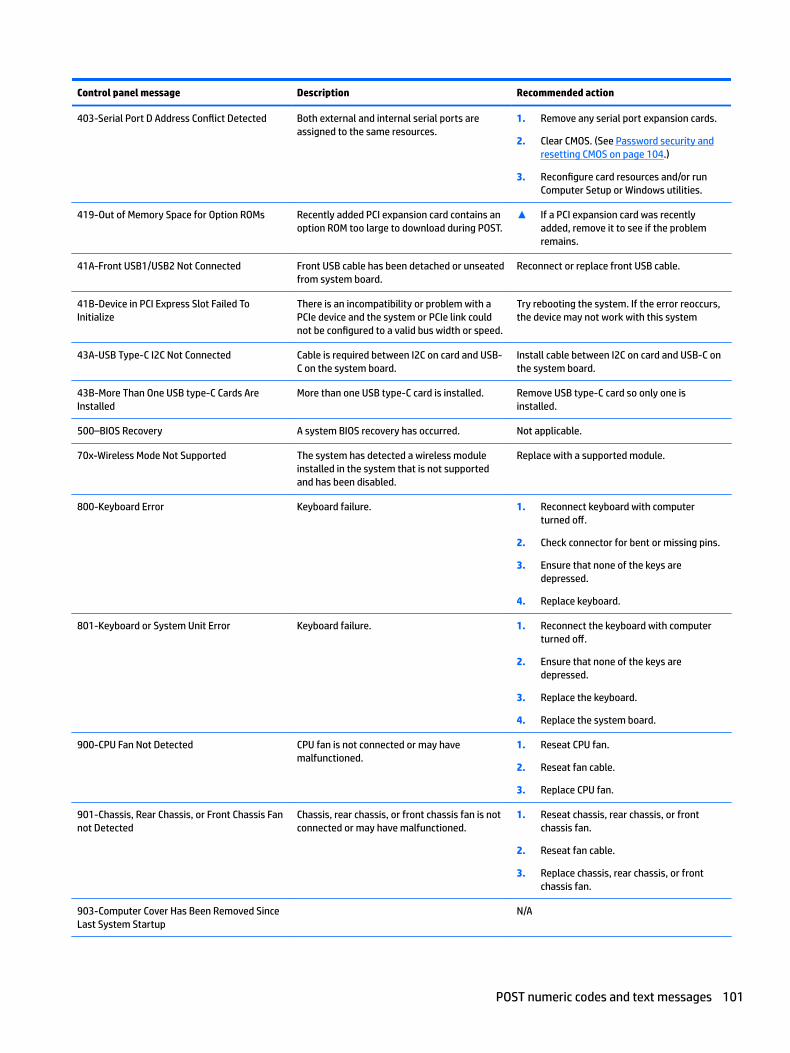
Control panel message Description Recommended action
403-Serial Port D Address Conflict Detected Both external and internal serial ports are assigned to the same resources.
1. Remove any serial port expansion cards.
2. Clear CMOS. (See Password security and resetting CMOS on page 104.)
3. Reconfigure card resources and/or run Computer Setup or Windows utilities.
419-Out of Memory Space for Option ROMs Recently added PCI expansion card contains an option ROM too large to download during POST.
▲ If a PCI expansion card was recently added, remove it to see if the problem remains.
41A-Front USB1/USB2 Not Connected Front USB cable has been detached or unseated from system board.
Reconnect or replace front USB cable.
41B-Device in PCI Express Slot Failed To Initialize
There is an incompatibility or problem with a PCIe device and the system or PCIe link could not be configured to a valid bus width or speed.
Try rebooting the system. If the error reoccurs, the device may not work with this system
43A-USB Type-C I2C Not Connected Cable is required between I2C on card and USB-C on the system board.
Install cable between I2C on card and USB-C on the system board.
43B-More Than One USB type-C Cards Are Installed
More than one USB type-C card is installed. Remove USB type-C card so only one is installed.
500–BIOS Recovery A system BIOS recovery has occurred. Not applicable.
70x-Wireless Mode Not Supported The system has detected a wireless module installed in the system that is not supported and has been disabled.
Replace with a supported module.
800-Keyboard Error Keyboard failure. 1. Reconnect keyboard with computer turned off.
2. Check connector for bent or missing pins.
3. Ensure that none of the keys are depressed.
4. Replace keyboard.
801-Keyboard or System Unit Error Keyboard failure. 1. Reconnect the keyboard with computer turned off.
2. Ensure that none of the keys are depressed.
3. Replace the keyboard.
4. Replace the system board.
900-CPU Fan Not Detected CPU fan is not connected or may have malfunctioned.
1. Reseat CPU fan.
2. Reseat fan cable.
3. Replace CPU fan.
901-Chassis, Rear Chassis, or Front Chassis Fan not Detected
Chassis, rear chassis, or front chassis fan is not connected or may have malfunctioned.
1. Reseat chassis, rear chassis, or front chassis fan.
2. Reseat fan cable.
3. Replace chassis, rear chassis, or front chassis fan.
903-Computer Cover Has Been Removed Since Last System Startup
N/A
POST numeric codes and text messages 101
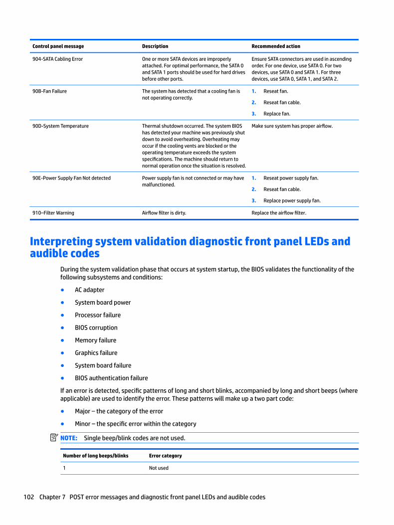
Control panel message Description Recommended action
904-SATA Cabling Error One or more SATA devices are improperly attached. For optimal performance, the SATA 0 and SATA 1 ports should be used for hard drives before other ports.
Ensure SATA connectors are used in ascending order. For one device, use SATA 0. For two devices, use SATA 0 and SATA 1. For three devices, use SATA 0, SATA 1, and SATA 2.
90B-Fan Failure The system has detected that a cooling fan is not operating correctly.
1. Reseat fan.
2. Reseat fan cable.
3. Replace fan.
90D-System Temperature Thermal shutdown occurred. The system BIOS has detected your machine was previously shut down to avoid overheating. Overheating may occur if the cooling vents are blocked or the operating temperature exceeds the system specifications. The machine should return to normal operation once the situation is resolved.
Make sure system has proper airflow.
90E-Power Supply Fan Not detected Power supply fan is not connected or may have malfunctioned.
1. Reseat power supply fan.
2. Reseat fan cable.
3. Replace power supply fan.
910–Filter Warning Airflow filter is dirty. Replace the airflow filter.
Interpreting system validation diagnostic front panel LEDs and audible codes
During the system validation phase that occurs at system startup, the BIOS validates the functionality of the following subsystems and conditions:
● AC adapter
● System board power
● Processor failure
● BIOS corruption
● Memory failure
● Graphics failure
● System board failure
● BIOS authentication failure
If an error is detected, specific patterns of long and short blinks, accompanied by long and short beeps (where applicable) are used to identify the error. These patterns will make up a two part code:
● Major – the category of the error
● Minor – the specific error within the category
NOTE: Single beep/blink codes are not used.
Number of long beeps/blinks Error category
1 Not used
102 Chapter 7 POST error messages and diagnostic front panel LEDs and audible codes
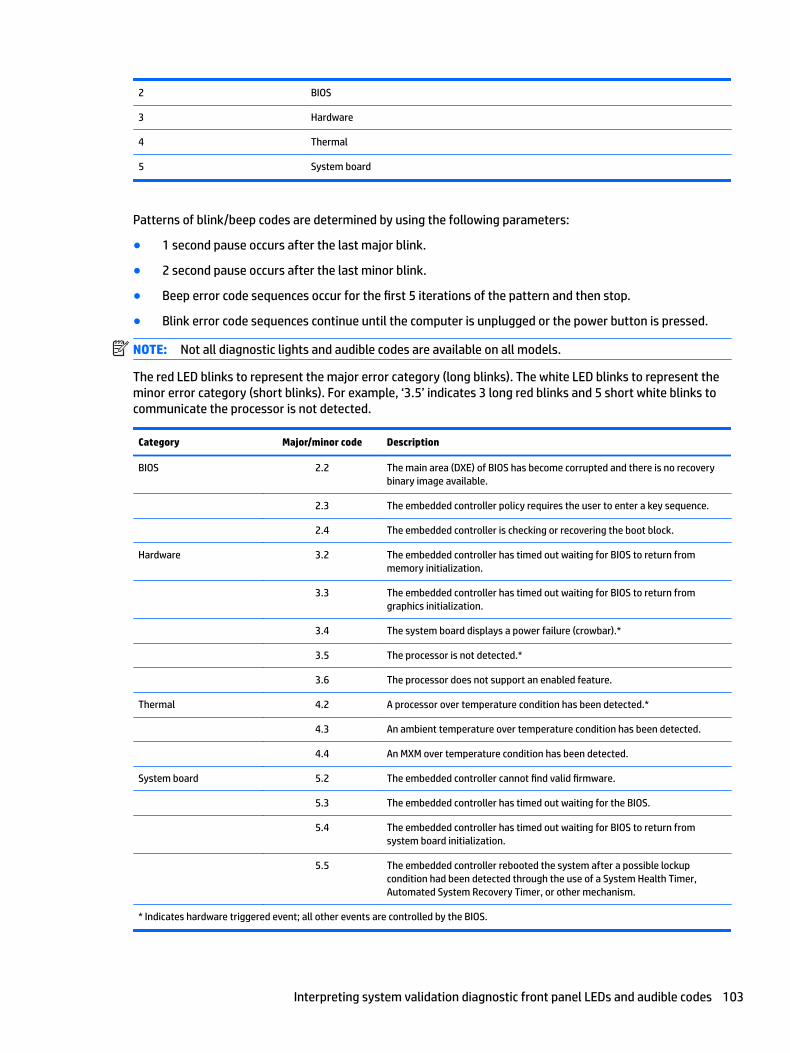
2 BIOS
3 Hardware
4 Thermal
5 System board
Patterns of blink/beep codes are determined by using the following parameters:
● 1 second pause occurs after the last major blink.
● 2 second pause occurs after the last minor blink.
● Beep error code sequences occur for the first 5 iterations of the pattern and then stop.
● Blink error code sequences continue until the computer is unplugged or the power button is pressed.
NOTE: Not all diagnostic lights and audible codes are available on all models.
The red LED blinks to represent the major error category (long blinks). The white LED blinks to represent the minor error category (short blinks). For example, ‘3.5’ indicates 3 long red blinks and 5 short white blinks to communicate the processor is not detected.
Category Major/minor code Description
BIOS 2.2 The main area (DXE) of BIOS has become corrupted and there is no recovery binary image available.
2.3 The embedded controller policy requires the user to enter a key sequence.
2.4 The embedded controller is checking or recovering the boot block.
Hardware 3.2 The embedded controller has timed out waiting for BIOS to return from memory initialization.
3.3 The embedded controller has timed out waiting for BIOS to return from graphics initialization.
3.4 The system board displays a power failure (crowbar).*
3.5 The processor is not detected.*
3.6 The processor does not support an enabled feature.
Thermal 4.2 A processor over temperature condition has been detected.*
4.3 An ambient temperature over temperature condition has been detected.
4.4 An MXM over temperature condition has been detected.
System board 5.2 The embedded controller cannot find valid firmware.
5.3 The embedded controller has timed out waiting for the BIOS.
5.4 The embedded controller has timed out waiting for BIOS to return from system board initialization.
5.5 The embedded controller rebooted the system after a possible lockup condition had been detected through the use of a System Health Timer, Automated System Recovery Timer, or other mechanism.
* Indicates hardware triggered event; all other events are controlled by the BIOS.
Interpreting system validation diagnostic front panel LEDs and audible codes 103
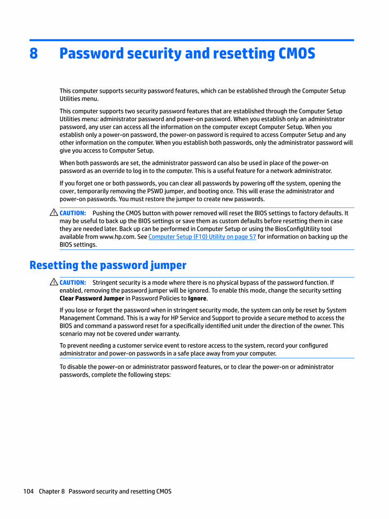
8 Password security and resetting CMOS
This computer supports security password features, which can be established through the Computer Setup Utilities menu.
This computer supports two security password features that are established through the Computer Setup Utilities menu: administrator password and power-on password. When you establish only an administrator password, any user can access all the information on the computer except Computer Setup. When you establish only a power-on password, the power-on password is required to access Computer Setup and any other information on the computer. When you establish both passwords, only the administrator password will give you access to Computer Setup.
When both passwords are set, the administrator password can also be used in place of the power-on password as an override to log in to the computer. This is a useful feature for a network administrator.
If you forget one or both passwords, you can clear all passwords by powering off the system, opening the cover, temporarily removing the PSWD jumper, and booting once. This will erase the administrator and power-on passwords. You must restore the jumper to create new passwords.
CAUTION: Pushing the CMOS button with power removed will reset the BIOS settings to factory defaults. It may be useful to back up the BIOS settings or save them as custom defaults before resetting them in case they are needed later. Back up can be performed in Computer Setup or using the BiosConfigUtility tool available from www.hp.com. See Computer Setup (F10) Utility on page 57 for information on backing up the BIOS settings.
Resetting the password jumperCAUTION: Stringent security is a mode where there is no physical bypass of the password function. If enabled, removing the password jumper will be ignored. To enable this mode, change the security setting Clear Password Jumper in Password Policies to Ignore.
If you lose or forget the password when in stringent security mode, the system can only be reset by System Management Command. This is a way for HP Service and Support to provide a secure method to access the BIOS and command a password reset for a specifically identified unit under the direction of the owner. This scenario may not be covered under warranty.
To prevent needing a customer service event to restore access to the system, record your configured administrator and power-on passwords in a safe place away from your computer.
To disable the power-on or administrator password features, or to clear the power-on or administrator passwords, complete the following steps:
104 Chapter 8 Password security and resetting CMOS
1. Shut down the operating system properly, then turn off the computer and any external devices, and disconnect the power cord from the power outlet.
2. With the power cord disconnected, press the power button again to drain the system of any residual power.
WARNING! To reduce the risk of personal injury from electrical shock and/or hot surfaces, be sure to disconnect the power cord from the wall outlet, and allow the internal system components to cool before touching.
CAUTION: When the computer is plugged in, the power supply always has voltage applied to the system board even when the unit is turned off. Failure to disconnect the power cord can result in damage to the system.
Static electricity can damage the electronic components of the computer or optional equipment. Before beginning these procedures, ensure that you are discharged of static electricity by briefly touching a grounded metal object. See the Safety & Regulatory Information guide for more information.
3. Remove the access panel.
4. Locate the header and jumper.
NOTE: The password jumper is green so that it can be easily identified. For assistance locating the password jumper and other system board components, see the system board components image at System board on page 50.
5. Remove the jumper from pins 1 and 2.
6. Place the jumper on either pin 1 or 2, but not both, so that it does not get lost.
7. Replace the access panel and reconnect the external equipment.
8. Plug in the computer and turn on power. Allow the operating system to start. This clears the current passwords and disables the password features.
9. Shut down the computer, unplug the power, and disconnect the external equipment.
10. Remove the access panel.
11. Place the jumper on pins 1 and 2.
12. Replace the access panel.
13. Reconnect the external equipment and plug in the computer.
Resetting the password jumper 105
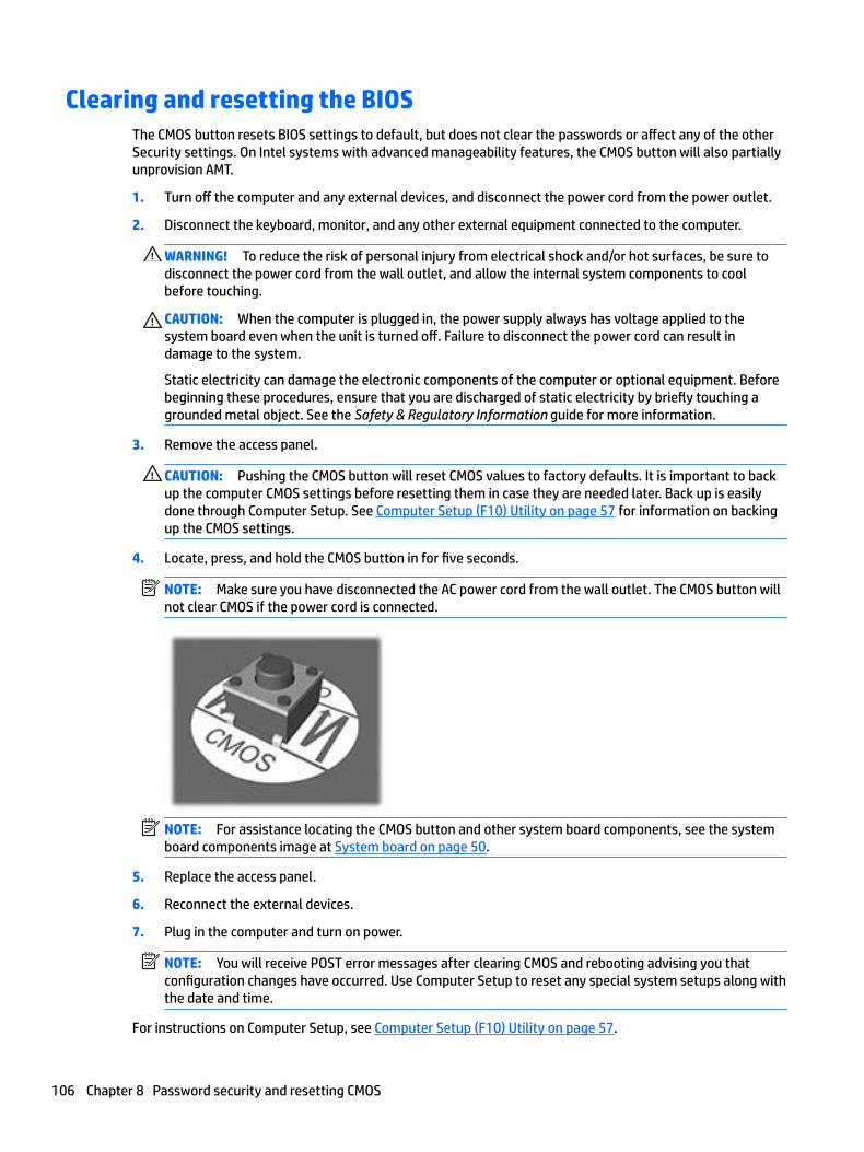
Clearing and resetting the BIOSThe CMOS button resets BIOS settings to default, but does not clear the passwords or affect any of the other Security settings. On Intel systems with advanced manageability features, the CMOS button will also partially unprovision AMT.
1. Turn off the computer and any external devices, and disconnect the power cord from the power outlet.
2. Disconnect the keyboard, monitor, and any other external equipment connected to the computer.
WARNING! To reduce the risk of personal injury from electrical shock and/or hot surfaces, be sure to disconnect the power cord from the wall outlet, and allow the internal system components to cool before touching.
CAUTION: When the computer is plugged in, the power supply always has voltage applied to the system board even when the unit is turned off. Failure to disconnect the power cord can result in damage to the system.
Static electricity can damage the electronic components of the computer or optional equipment. Before beginning these procedures, ensure that you are discharged of static electricity by briefly touching a grounded metal object. See the Safety & Regulatory Information guide for more information.
3. Remove the access panel.
CAUTION: Pushing the CMOS button will reset CMOS values to factory defaults. It is important to back up the computer CMOS settings before resetting them in case they are needed later. Back up is easily done through Computer Setup. See Computer Setup (F10) Utility on page 57 for information on backing up the CMOS settings.
4. Locate, press, and hold the CMOS button in for five seconds.
NOTE: Make sure you have disconnected the AC power cord from the wall outlet. The CMOS button will not clear CMOS if the power cord is connected.
NOTE: For assistance locating the CMOS button and other system board components, see the system board components image at System board on page 50.
5. Replace the access panel.
6. Reconnect the external devices.
7. Plug in the computer and turn on power.
NOTE: You will receive POST error messages after clearing CMOS and rebooting advising you that configuration changes have occurred. Use Computer Setup to reset any special system setups along with the date and time.
For instructions on Computer Setup, see Computer Setup (F10) Utility on page 57.
106 Chapter 8 Password security and resetting CMOS
9 Using HP PC Hardware Diagnostics (UEFI)
HP PC Hardware Diagnostics is a Unified Extensible Firmware Interface (UEFI) that allows you to run diagnostic tests to determine whether the computer hardware is functioning properly. The tool runs outside the operating system so that it can isolate hardware failures from issues that are caused by the operating system or other software components.
When HP PC Hardware Diagnostics (UEFI) detects a failure that requires hardware replacement, a 24-digit Failure ID code is generated. This ID code can then be provided to support to help determine how to correct the problem.
NOTE: To start diagnostics on a convertible computer, your computer must be in notebook mode and you must use the keyboard attached.
To start HP PC Hardware Diagnostics (UEFI), follow these steps:
1. Turn on or restart the computer, and quickly press esc.
2. Press f2.
The BIOS searches three places for the diagnostic tools, in the following order:
a. Connected USB drive
NOTE: To download the HP PC Hardware Diagnostics (UEFI) tool to a USB drive, see Downloading HP PC Hardware Diagnostics (UEFI) to a USB device on page 107.
b. Hard drive
c. BIOS
3. When the diagnostic tool opens, select the type of diagnostic test you want to run, and then follow the on-screen instructions.
NOTE: If you need to stop a diagnostic test, press esc.
Downloading HP PC Hardware Diagnostics (UEFI) to a USB deviceNOTE: The HP PC Hardware Diagnostics (UEFI) download instructions are provided in English only, and you must use a Windows computer to download and create the HP UEFI support environment because only .exe files are offered.
There are two options to download HP PC Hardware Diagnostics to a USB device.
Download the latest UEFI version
1. Go to http://www.hp.com/go/techcenter/pcdiags. The HP PC Diagnostics home page is displayed.
2. In the HP PC Hardware Diagnostics section, select the Download link, and then select Run.
Download any version of UEFI for a specific product
1. Go to http://www.hp.com/support.
2. Select Get software and drivers.
Downloading HP PC Hardware Diagnostics (UEFI) to a USB device 107

3. Enter the product name or number.
– or –
Select Identify now to let HP automatically detect your product.
4. Select your computer, and then select your operating system.
5. In the Diagnostic section, follow the on-screen instructions to select and download the UEFI version you want.
108 Chapter 9 Using HP PC Hardware Diagnostics (UEFI)
10 System backup and recovery
Backing up, restoring, and recovering in Windows 7Your computer includes tools provided by HP and Windows to help you safeguard your information and retrieve it if you ever need to. These tools will help you return your computer to a proper working state or even back to the original factory state, all with simple steps.
This section provides information about the following processes:
● Creating recovery media and backups
● Restoring and recovering your system
NOTE: This section describes an overview of backing up, restoring, and recovering options. For more details about the Windows Backup and Restore tools provided, see Help and Support. To access Help and Support, select Start > Help and Support.
Recovery after a system failure is only as good as your most recent backup.
1. After you successfully set up the computer, create recovery media. This media can be used to reinstall the original operating system in cases where the hard drive is corrupted or has been replaced. See Creating recovery media on page 109.
2. As you add hardware and software programs, create system restore points. A system restore point is a snapshot of certain hard drive contents saved by Windows System Restore at a specific time. A system restore point contains information that Windows uses, such as registry settings. Windows creates a system restore point for you automatically during a Windows update and during other system maintenance (such as a software update, security scanning, or system diagnostics). You can also manually create a system restore point at any time. For more information and steps for creating specific system restore points, see Help and Support. To access Help and Support, select Start > Help and Support.
3. As you add photos, video, music, and other personal files, create a backup of your personal information. If files are accidentally deleted from the hard drive and they can no longer be restored from the Recycle Bin, or if files become corrupted, you can restore the files that you backed up. In case of system failure, you can use the backup files to restore the contents of your computer. See Backing up your information on page 111.
NOTE: HP recommends that you print the recovery procedures and save them for later use, in case of system instability.
Creating recovery media
After you successfully set up the computer, create recovery media. The media can be used to reinstall the original operating system in cases where the hard drive is corrupted or has been replaced.
There are two types of recovery media. To determine which steps to follow for your computer:
1. Click the Start button.
2. Click All Programs.
Backing up, restoring, and recovering in Windows 7 109
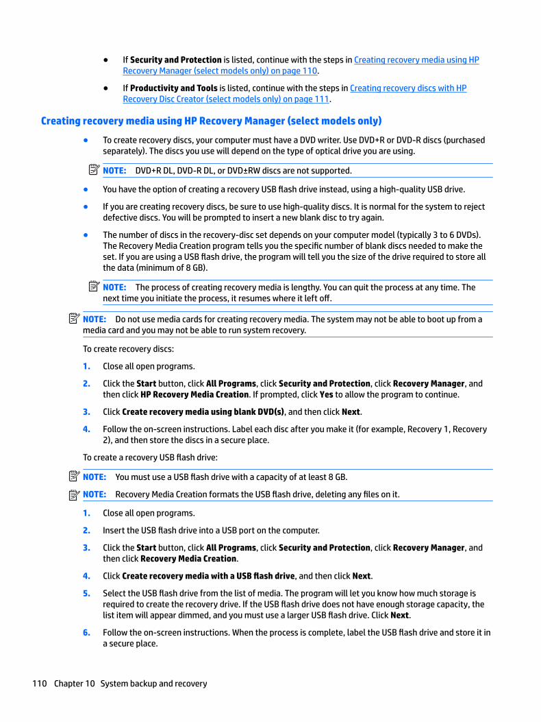
● If Security and Protection is listed, continue with the steps in Creating recovery media using HP Recovery Manager (select models only) on page 110.
● If Productivity and Tools is listed, continue with the steps in Creating recovery discs with HP Recovery Disc Creator (select models only) on page 111.
Creating recovery media using HP Recovery Manager (select models only)
● To create recovery discs, your computer must have a DVD writer. Use DVD+R or DVD-R discs (purchased separately). The discs you use will depend on the type of optical drive you are using.
NOTE: DVD+R DL, DVD-R DL, or DVD±RW discs are not supported.
● You have the option of creating a recovery USB flash drive instead, using a high-quality USB drive.
● If you are creating recovery discs, be sure to use high-quality discs. It is normal for the system to reject defective discs. You will be prompted to insert a new blank disc to try again.
● The number of discs in the recovery-disc set depends on your computer model (typically 3 to 6 DVDs). The Recovery Media Creation program tells you the specific number of blank discs needed to make the set. If you are using a USB flash drive, the program will tell you the size of the drive required to store all the data (minimum of 8 GB).
NOTE: The process of creating recovery media is lengthy. You can quit the process at any time. The next time you initiate the process, it resumes where it left off.
NOTE: Do not use media cards for creating recovery media. The system may not be able to boot up from a media card and you may not be able to run system recovery.
To create recovery discs:
1. Close all open programs.
2. Click the Start button, click All Programs, click Security and Protection, click Recovery Manager, and then click HP Recovery Media Creation. If prompted, click Yes to allow the program to continue.
3. Click Create recovery media using blank DVD(s), and then click Next.
4. Follow the on-screen instructions. Label each disc after you make it (for example, Recovery 1, Recovery 2), and then store the discs in a secure place.
To create a recovery USB flash drive:
NOTE: You must use a USB flash drive with a capacity of at least 8 GB.
NOTE: Recovery Media Creation formats the USB flash drive, deleting any files on it.
1. Close all open programs.
2. Insert the USB flash drive into a USB port on the computer.
3. Click the Start button, click All Programs, click Security and Protection, click Recovery Manager, and then click Recovery Media Creation.
4. Click Create recovery media with a USB flash drive, and then click Next.
5. Select the USB flash drive from the list of media. The program will let you know how much storage is required to create the recovery drive. If the USB flash drive does not have enough storage capacity, the list item will appear dimmed, and you must use a larger USB flash drive. Click Next.
6. Follow the on-screen instructions. When the process is complete, label the USB flash drive and store it in a secure place.
110 Chapter 10 System backup and recovery
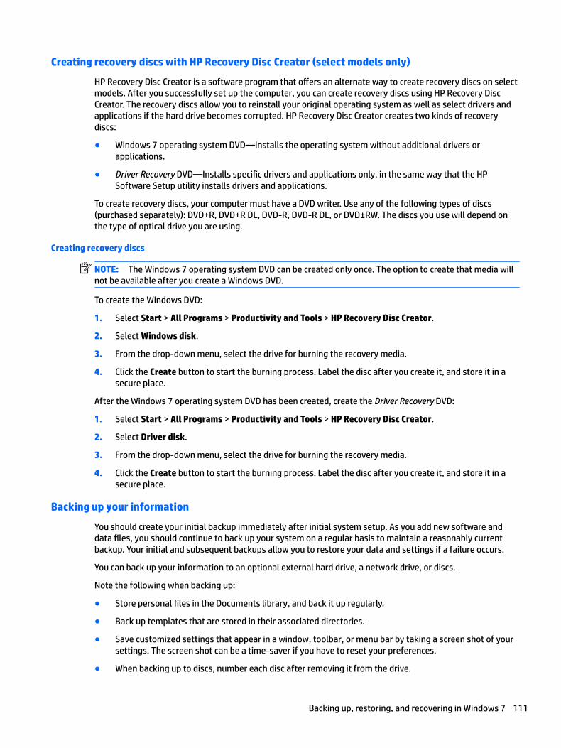
Creating recovery discs with HP Recovery Disc Creator (select models only)
HP Recovery Disc Creator is a software program that offers an alternate way to create recovery discs on select models. After you successfully set up the computer, you can create recovery discs using HP Recovery Disc Creator. The recovery discs allow you to reinstall your original operating system as well as select drivers and applications if the hard drive becomes corrupted. HP Recovery Disc Creator creates two kinds of recovery discs:
● Windows 7 operating system DVD—Installs the operating system without additional drivers or applications.
● Driver Recovery DVD—Installs specific drivers and applications only, in the same way that the HP Software Setup utility installs drivers and applications.
To create recovery discs, your computer must have a DVD writer. Use any of the following types of discs (purchased separately): DVD+R, DVD+R DL, DVD-R, DVD-R DL, or DVD±RW. The discs you use will depend on the type of optical drive you are using.
Creating recovery discs
NOTE: The Windows 7 operating system DVD can be created only once. The option to create that media will not be available after you create a Windows DVD.
To create the Windows DVD:
1. Select Start > All Programs > Productivity and Tools > HP Recovery Disc Creator.
2. Select Windows disk.
3. From the drop-down menu, select the drive for burning the recovery media.
4. Click the Create button to start the burning process. Label the disc after you create it, and store it in a secure place.
After the Windows 7 operating system DVD has been created, create the Driver Recovery DVD:
1. Select Start > All Programs > Productivity and Tools > HP Recovery Disc Creator.
2. Select Driver disk.
3. From the drop-down menu, select the drive for burning the recovery media.
4. Click the Create button to start the burning process. Label the disc after you create it, and store it in a secure place.
Backing up your information
You should create your initial backup immediately after initial system setup. As you add new software and data files, you should continue to back up your system on a regular basis to maintain a reasonably current backup. Your initial and subsequent backups allow you to restore your data and settings if a failure occurs.
You can back up your information to an optional external hard drive, a network drive, or discs.
Note the following when backing up:
● Store personal files in the Documents library, and back it up regularly.
● Back up templates that are stored in their associated directories.
● Save customized settings that appear in a window, toolbar, or menu bar by taking a screen shot of your settings. The screen shot can be a time-saver if you have to reset your preferences.
● When backing up to discs, number each disc after removing it from the drive.
Backing up, restoring, and recovering in Windows 7 111
NOTE: For detailed instructions on various backup and restore options, perform a search for these topics in Help and Support. To access Help and Support, select Start > Help and Support.
NOTE: You may be prompted by User Account Control for your permission or password when you perform certain tasks. To continue a task, select the appropriate option. For information about User Account Control, see Help and Support: Select Start > Help and Support.
To create a backup using Windows Backup and Restore:
NOTE: The backup process may take over an hour, depending on file size and the speed of the computer.
1. Select Start > All Programs > Maintenance > Backup and Restore.
2. Follow the on-screen instructions to set up your backup.
System Restore
If you have a problem that might be due to software that you installed on your computer, or if you want to restore the system to a previous state without losing any personal information, use System Restore to return the computer to a previous restore point.
NOTE: Always use this System Restore procedure before you use the System Recovery feature.
To start System Restore:
1. Close all open programs.
2. Click the Start button, right-click Computer, and then click Properties.
3. Click System protection, click System Restore, click Next, and then follow the on-screen instructions.
System Recovery
WARNING! This procedure deletes all user information. To prevent loss of information, be sure to back up all user information so you can restore it after recovery.
System Recovery completely erases and reformats the hard drive, deleting all data files that you have created, and then reinstalls the operating system, programs, and drivers. However, you must reinstall any software that was not installed on the computer at the factory. This includes software that came on media included in the computer accessory box, and any software programs you installed after purchase. Any personal files must be restored from backups you made.
If you were not able to create system recovery DVDs or USB flash drive, you can order a recovery disc set from support. Go to http://www.hp.com/support, select your country or region, and follow the on-screen instructions.
NOTE: Always use the System Restore procedure before you use the System Recovery program. See System Restore on page 112.
You must choose one of the following methods to perform a System Recovery:
● Recovery image — Run System Recovery from a recovery image stored on your hard drive. The recovery image is a file that contains a copy of the original factory-shipped software. To perform a System Recovery from a recovery image, see System Recovery when Windows is responding on page 113 or System Recovery when Windows is not responding on page 113.
● Recovery media — Run System Recovery from recovery media that you have created from files stored on your hard drive or purchased separately. See System Recovery using recovery media (select models only) on page 114.
112 Chapter 10 System backup and recovery
System Recovery when Windows is responding
CAUTION: System Recovery deletes all data and programs you have created or installed. Before you begin, back up any important data to a CD or DVD or to a USB flash drive.
NOTE: In some cases, you must use recovery media for this procedure. If you have not already created this media, follow the instructions in Creating recovery media on page 109.
If the computer is working and Windows 7 is responding, use these steps to perform a System Recovery:
1. Turn off the computer.
2. Disconnect all peripheral devices from the computer except the monitor, keyboard, and mouse.
3. Turn on the computer.
4. When Windows has loaded, click the Start button, and then click All Programs.
● If Security and Protection is listed, continue with step 5.
● If Productivity and Tools is listed, follow the steps in System Recovery when Windows is not responding on page 113.
5. Click Security and Protection, click Recovery Manager, and then click Recovery Manager. If prompted, click Yes to allow the program to continue.
6. Under I need help immediately, click System Recovery.
7. Select Yes, and then click Next. Your computer restarts.
8. When the computer restarts, you will see the Recovery Manager welcome screen again. Under I need help immediately, click System Recovery. If you are prompted to back up your files, and you have not done so, select Back up your files first (recommended), and then click Next. Otherwise, select Recover without backing up your files, and then click Next.
9. System Recovery begins. After System Recovery is complete, click Finish to restart the computer.
10. When Windows has loaded, shut down the computer, reconnect all peripheral devices, and then turn the computer back on.
System Recovery when Windows is not responding
CAUTION: System Recovery deletes all data and programs you have created or installed.
If Windows is not responding, but the computer is working, follow these steps to perform a System Recovery.
1. Turn off the computer. If necessary, press and hold the power button until the computer turns off.
2. Disconnect all peripheral devices from the computer except the monitor, keyboard, and mouse.
3. Press the power button to turn on the computer.
4. As soon as you see the HP logo screen, repeatedly press the F11 key on your keyboard until the Windows is Loading Files… message appears on the screen.
5. At the HP Recovery Manager screen, follow the on-screen instructions to continue.
6. When Windows has loaded, shut down the computer, reconnect all peripheral devices, and then turn the computer back on.
Backing up, restoring, and recovering in Windows 7 113
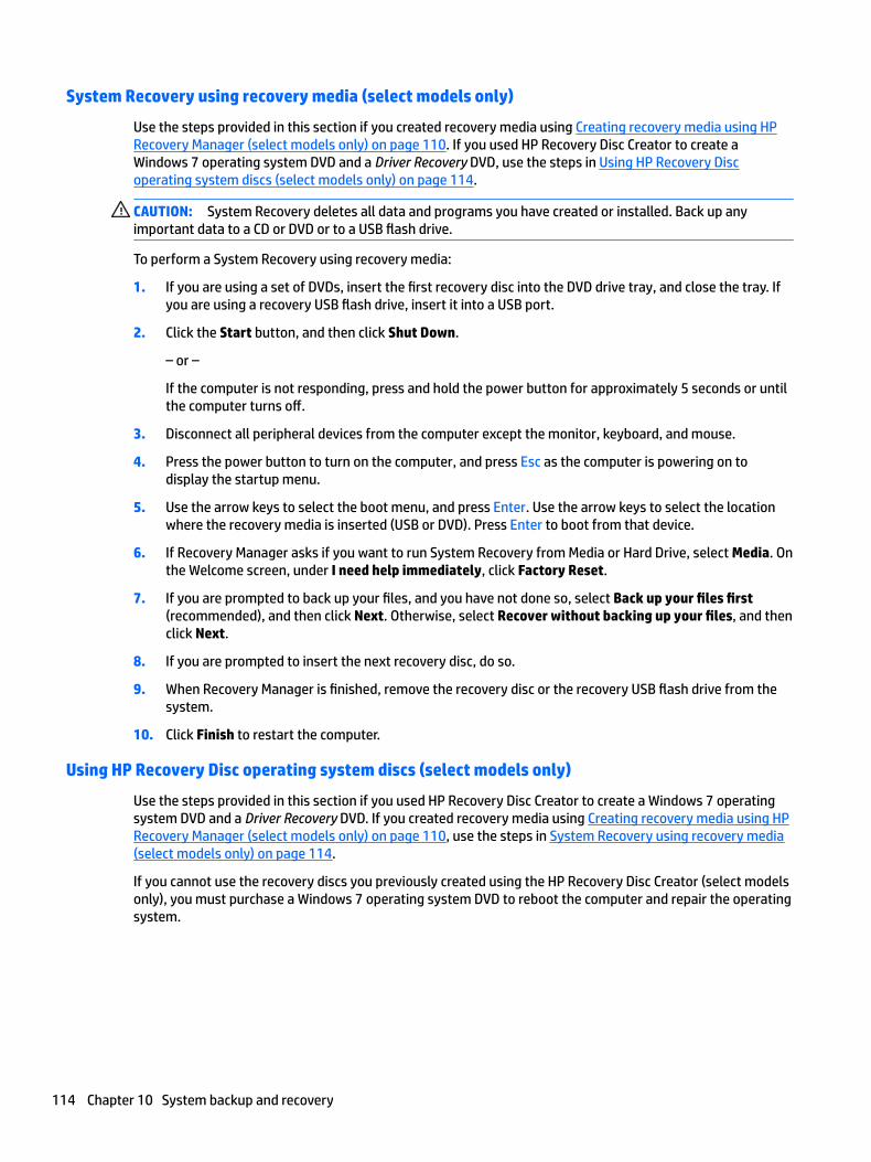
System Recovery using recovery media (select models only)
Use the steps provided in this section if you created recovery media using Creating recovery media using HP Recovery Manager (select models only) on page 110. If you used HP Recovery Disc Creator to create a Windows 7 operating system DVD and a Driver Recovery DVD, use the steps in Using HP Recovery Disc operating system discs (select models only) on page 114.
CAUTION: System Recovery deletes all data and programs you have created or installed. Back up any important data to a CD or DVD or to a USB flash drive.
To perform a System Recovery using recovery media:
1. If you are using a set of DVDs, insert the first recovery disc into the DVD drive tray, and close the tray. If you are using a recovery USB flash drive, insert it into a USB port.
2. Click the Start button, and then click Shut Down.
– or –
If the computer is not responding, press and hold the power button for approximately 5 seconds or until the computer turns off.
3. Disconnect all peripheral devices from the computer except the monitor, keyboard, and mouse.
4. Press the power button to turn on the computer, and press Esc as the computer is powering on to display the startup menu.
5. Use the arrow keys to select the boot menu, and press Enter. Use the arrow keys to select the location where the recovery media is inserted (USB or DVD). Press Enter to boot from that device.
6. If Recovery Manager asks if you want to run System Recovery from Media or Hard Drive, select Media. On the Welcome screen, under I need help immediately, click Factory Reset.
7. If you are prompted to back up your files, and you have not done so, select Back up your files first (recommended), and then click Next. Otherwise, select Recover without backing up your files, and then click Next.
8. If you are prompted to insert the next recovery disc, do so.
9. When Recovery Manager is finished, remove the recovery disc or the recovery USB flash drive from the system.
10. Click Finish to restart the computer.
Using HP Recovery Disc operating system discs (select models only)
Use the steps provided in this section if you used HP Recovery Disc Creator to create a Windows 7 operating system DVD and a Driver Recovery DVD. If you created recovery media using Creating recovery media using HP Recovery Manager (select models only) on page 110, use the steps in System Recovery using recovery media (select models only) on page 114.
If you cannot use the recovery discs you previously created using the HP Recovery Disc Creator (select models only), you must purchase a Windows 7 operating system DVD to reboot the computer and repair the operating system.
114 Chapter 10 System backup and recovery
To order a Windows 7 operating system DVD, contact support. Go to http://www.hp.com/support, select your country or region, and follow the on-screen instructions.
CAUTION: Using a Windows 7 operating system DVD completely erases the hard drive contents and reformats the hard drive. All files that you have created and any software that you have installed on the computer are permanently removed. When reformatting is complete, the recovery process helps you restore the operating system, as well as drivers, software, and utilities.
To initiate recovery using a Windows 7 operating system DVD:
NOTE: This process takes several minutes.
1. If possible, back up all personal files.
2. Restart the computer, and then insert the Windows 7 operating system DVD into the optical drive before the Windows operating system loads.
NOTE: If the computer does not boot to the DVD, restart the computer and press Esc as the computer is powering on to see the startup menu. Use the arrow keys to select the boot menu and press Enter. Use the arrow keys to select the location where the recovery DVD is inserted. Press Enter to boot from that device.
3. When prompted, press any keyboard key.
4. Follow the on-screen instructions.
5. Click Next.
6. Select Install now.
7. Follow the on-screen instructions.
After the repair is completed:
1. Eject the Windows 7 operating system DVD and then insert the Driver Recovery DVD.
2. Follow the on-screen instructions to install the Hardware Enabling Drivers first, and then install Recommended Applications.
Backing up, restoring, and recovering in Windows 10This section provides information about the following processes. The information in the section is standard procedure for most products.
● Creating recovery media and backups
● Restoring and recovering your system
For additional information, refer to the HP Support Assistant app.
▲ Type support in the taskbar search box, and then select the Help Support Assistant app.
– or –
Select the question mark icon in the taskbar.
Creating recovery media and backups
The following methods of creating recovery media and backups are available on select products only. Choose the method according to your computer model.
Backing up, restoring, and recovering in Windows 10 115
● Use HP Recovery Manager to create HP Recovery media after you successfully set up the computer. This step creates a backup of the HP Recovery partition on the computer. The backup can be used to reinstall the original operating system in cases where the hard drive is corrupted or has been replaced. For information on creating recovery media, see Creating HP Recovery media (select products only) on page 116. For information on the recovery options that are available using the recovery media, see What you need to know before you get started on page 118.
● Use Windows tools to create system restore points and create backups of personal information.
For more information, see Using Windows tools on page 117.
NOTE: If storage is 32 GB or less, Microsoft System Restore is disabled by default.
Creating HP Recovery media (select products only)
If possible, check for the presence of the Recovery partition and the Windows partition. From the Start menu, select File Explorer, and then select This PC.
● If your computer does not list the Windows partition and the Recovery partition, you can obtain recovery media for your system from support. See the Worldwide Telephone Numbers booklet included with the computer. You can also find contact information on the HP website. Go to http://www.hp.com/support, select your country or region, and follow the on-screen instructions.
You can use Windows tools to create system restore points and create backups of personal information, see Using Windows tools on page 117.
● If your computer does list the Recovery partition and the Windows partition, you can use HP Recovery Manager to create recovery media after you successfully set up the computer. HP Recovery media can be used to perform system recovery if the hard drive becomes corrupted. System recovery reinstalls the original operating system and software programs that were installed at the factory and then configures the settings for the programs. HP Recovery media can also be used to customize the system or restore the factory image if you replace the hard drive.
○ Only one set of recovery media can be created. Handle these recovery tools carefully, and keep them in a safe place.
○ HP Recovery Manager examines the computer and determines the required storage capacity for the media that will be required.
○ To create recovery discs, your computer must have an optical drive with DVD writer capability, and you must use only high-quality blank DVD-R, DVD+R, DVD-R DL, or DVD+R DL discs. Do not use rewritable discs such as CD±RW, DVD±RW, double-layer DVD±RW, or BD-RE (rewritable Blu-ray) discs; they are not compatible with HP Recovery Manager software. Or, instead, you can use a high-quality blank USB flash drive.
○ If your computer does not include an integrated optical drive with DVD writer capability, but you would like to create DVD recovery media, you can use an external optical drive (purchased separately) to create recovery discs. If you use an external optical drive, it must be connected directly to a USB port on the computer; the drive cannot be connected to a USB port on an external device, such as a USB hub. If you cannot create DVD media yourself, you can obtain recovery discs for your computer from HP. See the Worldwide Telephone Numbers booklet included with the computer. You can also find contact information on the HP website. Go to http://www.hp.com/support, select your country or region, and follow the on-screen instructions.
○ Be sure that the computer is connected to AC power before you begin creating the recovery media.
116 Chapter 10 System backup and recovery
○ The creation process can take an hour or more. Do not interrupt the creation process.
○ If necessary, you can exit the program before you have finished creating all of the recovery DVDs. HP Recovery Manager will finish burning the current DVD. The next time you start HP Recovery Manager, you will be prompted to continue.
To create HP Recovery media:
1. Type recovery in the taskbar search box, and then select HP Recovery Manager.
2. Select Create recovery media, and then follow the on-screen instructions.
If you ever need to recover the system, see Recovering using HP Recovery Manager on page 118.
Using Windows tools
You can create recovery media, system restore points, and backups of personal information using Windows tools.
NOTE: If storage is 32 GB or less, Microsoft System Restore is disabled by default.
For more information and steps, see the Get started app.
▲ Select the Start button, and then select the Get started app.
Restore and recovery
There are several options for recovering your system. Choose the method that best matches your situation and level of expertise:
IMPORTANT: Not all methods are available on all products.
● Windows offers several options for restoring from backup, refreshing the computer, and resetting the computer to its original state. For more information see the Get started app.
▲ Select the Start button, and then select the Get started app.
● If you need to correct a problem with a preinstalled application or driver, use the Reinstall drivers and/ or applications option (select products only) of HP Recovery Manager to reinstall the individual application or driver.
▲ Type recovery in the taskbar search box, select HP Recovery Manager, select Reinstall drivers and/or applications, and then follow the on-screen instructions.
● If you want to recover the Windows partition to original factory content, you can choose the System Recovery option from the HP Recovery partition (select products only) or use the HP Recovery media. For more information, see Recovering using HP Recovery Manager on page 118. If you have not already created recovery media, see Creating HP Recovery media (select products only) on page 116.
● On select products, if you want to recover the computer's original factory partition and content, or if you have replaced the hard drive, you can use the Factory Reset option of HP Recovery media. For more information, see Recovering using HP Recovery Manager on page 118.
● On select products, if you want to remove the Recovery partition to reclaim hard drive space, HP Recovery Manager offers the Remove Recovery Partition option.
For more information, see Removing the HP Recovery partition (select products only) on page 119.
Backing up, restoring, and recovering in Windows 10 117
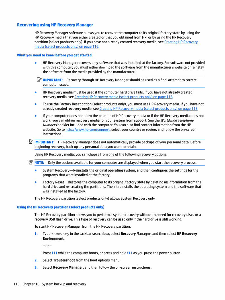
Recovering using HP Recovery Manager
HP Recovery Manager software allows you to recover the computer to its original factory state by using the HP Recovery media that you either created or that you obtained from HP, or by using the HP Recovery partition (select products only). If you have not already created recovery media, see Creating HP Recovery media (select products only) on page 116.
What you need to know before you get started
● HP Recovery Manager recovers only software that was installed at the factory. For software not provided with this computer, you must either download the software from the manufacturer's website or reinstall the software from the media provided by the manufacturer.
IMPORTANT: Recovery through HP Recovery Manager should be used as a final attempt to correct computer issues.
● HP Recovery media must be used if the computer hard drive fails. If you have not already created recovery media, see Creating HP Recovery media (select products only) on page 116.
● To use the Factory Reset option (select products only), you must use HP Recovery media. If you have not already created recovery media, see Creating HP Recovery media (select products only) on page 116.
● If your computer does not allow the creation of HP Recovery media or if the HP Recovery media does not work, you can obtain recovery media for your system from support. See the Worldwide Telephone Numbers booklet included with the computer. You can also find contact information from the HP website. Go to http://www.hp.com/support, select your country or region, and follow the on-screen instructions.
IMPORTANT: HP Recovery Manager does not automatically provide backups of your personal data. Before beginning recovery, back up any personal data you want to retain.
Using HP Recovery media, you can choose from one of the following recovery options:
NOTE: Only the options available for your computer are displayed when you start the recovery process.
● System Recovery—Reinstalls the original operating system, and then configures the settings for the programs that were installed at the factory.
● Factory Reset—Restores the computer to its original factory state by deleting all information from the hard drive and re-creating the partitions. Then it reinstalls the operating system and the software that was installed at the factory.
The HP Recovery partition (select products only) allows System Recovery only.
Using the HP Recovery partition (select products only)
The HP Recovery partition allows you to perform a system recovery without the need for recovery discs or a recovery USB flash drive. This type of recovery can be used only if the hard drive is still working.
To start HP Recovery Manager from the HP Recovery partition:
1. Type recovery in the taskbar search box, select Recovery Manager, and then select HP Recovery Environment.
– or –
Press f11 while the computer boots, or press and hold f11 as you press the power button.
2. Select Troubleshoot from the boot options menu.
3. Select Recovery Manager, and then follow the on-screen instructions.
118 Chapter 10 System backup and recovery

Using HP Recovery media to recover
You can use HP Recovery media to recover the original system. This method can be used if your system does not have an HP Recovery partition or if the hard drive is not working properly.
1. If possible, back up all personal files.
2. Insert the HP Recovery media, and then restart the computer.
NOTE: If the computer does not automatically restart in HP Recovery Manager, change the computer boot order. See Changing the computer boot order on page 119.
3. Follow the on-screen instructions.
Changing the computer boot order
If your computer does not restart in HP Recovery Manager, you can change the computer boot order, which is the order of devices listed in BIOS where the computer looks for startup information. You can change the selection to an optical drive or a USB flash drive.
To change the boot order:
1. Insert the HP Recovery media.
2. Access the system Startup menu:
Turn on or restart the computer, quickly press esc, and then press f9 for boot options.
3. Select the optical drive or USB flash drive from which you want to boot.
4. Follow the on-screen instructions.
Removing the HP Recovery partition (select products only)
HP Recovery Manager software allows you to remove the HP Recovery partition to free up hard drive space.
IMPORTANT: After you remove the HP Recovery partition, you will not be able to perform System Recovery or create HP Recovery media from the HP Recovery partition. So before you remove the Recovery partition, create HP Recovery media; see Creating HP Recovery media (select products only) on page 116.
NOTE: The Remove Recovery Partition option is only available on products that support this function.
Follow these steps to remove the HP Recovery partition:
1. Type recovery in the taskbar search box, and then select HP Recovery Manager.
2. Select Remove Recovery Partition, and then follow the on-screen instructions.
Backing up, restoring, and recovering in Windows 10 119
A Power Cord Set Requirements
The power supplies on some computers have external power switches. The voltage select switch feature on the computer permits it to operate from any line voltage between 100-120 or 220-240 volts AC. Power supplies on those computers that do not have external power switches are equipped with internal switches that sense the incoming voltage and automatically switch to the proper voltage.
The power cord set received with the computer meets the requirements for use in the country where you purchased the equipment.
Power cord sets for use in other countries must meet the requirements of the country where you use the computer.
General RequirementsThe requirements listed below are applicable to all countries:
1. The power cord must be approved by an acceptable accredited agency responsible for evaluation in the country where the power cord set will be installed.
2. The power cord set must have a minimum current capacity of 10A (7A Japan only) and a nominal voltage rating of 125 or 250 volts AC, as required by each country’s power system.
3. The diameter of the wire must be a minimum of 0.75 mm2 or 18AWG, and the length of the cord must be between 1.8 m (6 feet) and 3.6 m (12 feet).
The power cord should be routed so that it is not likely to be walked on or pinched by items placed upon it or against it. Particular attention should be paid to the plug, electrical outlet, and the point where the cord exits from the product.
WARNING! Do not operate this product with a damaged power cord set. If the power cord set is damaged in any manner, replace it immediately.
Japanese Power Cord RequirementsFor use in Japan, use only the power cord received with this product.
CAUTION: Do not use the power cord received with this product on any other products.
120 Appendix A Power Cord Set Requirements
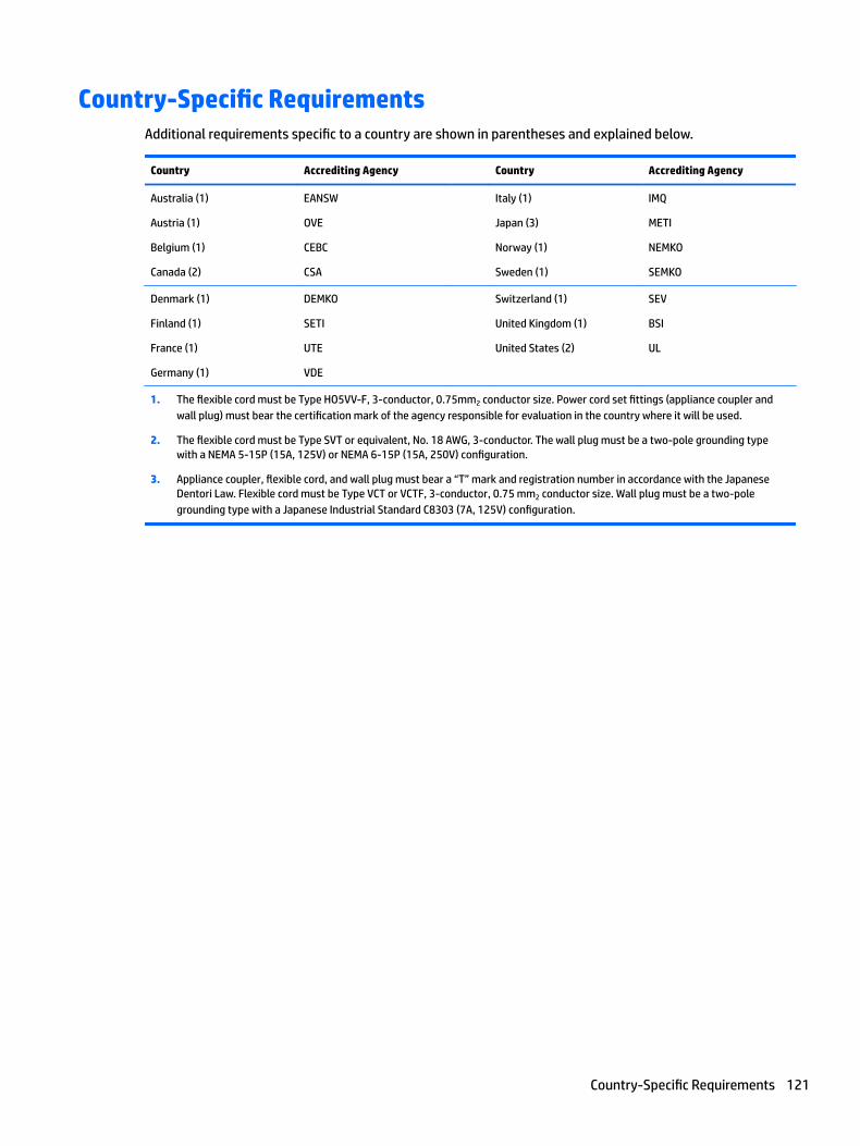
Country-Specific RequirementsAdditional requirements specific to a country are shown in parentheses and explained below.
Country Accrediting Agency Country Accrediting Agency
Australia (1)
Austria (1)
Belgium (1)
Canada (2)
EANSW
OVE
CEBC
CSA
Italy (1)
Japan (3)
Norway (1)
Sweden (1)
IMQ
METI
NEMKO
SEMKO
Denmark (1)
Finland (1)
France (1)
Germany (1)
DEMKO
SETI
UTE
VDE
Switzerland (1)
United Kingdom (1)
United States (2)
SEV
BSI
UL
1. The flexible cord must be Type HO5VV-F, 3-conductor, 0.75mm2 conductor size. Power cord set fittings (appliance coupler and wall plug) must bear the certification mark of the agency responsible for evaluation in the country where it will be used.
2. The flexible cord must be Type SVT or equivalent, No. 18 AWG, 3-conductor. The wall plug must be a two-pole grounding type with a NEMA 5-15P (15A, 125V) or NEMA 6-15P (15A, 250V) configuration.
3. Appliance coupler, flexible cord, and wall plug must bear a “T” mark and registration number in accordance with the Japanese Dentori Law. Flexible cord must be Type VCT or VCTF, 3-conductor, 0.75 mm2 conductor size. Wall plug must be a two-pole grounding type with a Japanese Industrial Standard C8303 (7A, 125V) configuration.
Country-Specific Requirements 121
B Statement of memory volatility
The purpose of this chapter is to provide general information regarding nonvolatile memory in HP Business computers. This chapter also provides general instructions for restoring nonvolatile memory that can contain personal data after the system has been powered off and the hard drive has been removed.
HP Business computer products that use Intel®-based or AMD®-based system boards contain volatile DDR memory. The amount of nonvolatile memory present in the system depends upon the system configuration. Intel-based and AMD-based system boards contain nonvolatile memory subcomponents as originally shipped from HP, assuming that no subsequent modifications have been made to the system and assuming that no applications, features, or functionality have been added to or installed on the system.
Following system shutdown and removal of all power sources from an HP Business computer system, personal data can remain on volatile system memory (DIMMs) for a finite period of time and will also remain in nonvolatile memory. Use the steps below to remove personal data from the computer, including the nonvolatile memory found in Intel-based and AMD-based system boards.
NOTE: If your tablet has a keyboard base, connect to the keyboard base before beginning steps in this chapter.
Current BIOS steps
1. Follow steps (a) through (l) below to restore the nonvolatile memory that can contain personal data. Restoring or reprogramming nonvolatile memory that does not store personal data is neither necessary nor recommended.
a. Turn on or restart the computer, and then press esc while the “Press the ESC key for Startup Menu” message is displayed at the bottom of the screen.
NOTE: If the system has a BIOS administrator password, enter the password at the prompt.
b. Select Main, select Apply Factory Defaults and Exit, and then select Yes to load defaults.
The computer will reboot.
c. During the reboot, press esc while the “Press the ESC key for Startup Menu” message is displayed at the bottom of the screen.
NOTE: If the system has a BIOS administrator password, enter the password at the prompt.
d. Select the Security menu, select Restore Security Settings to Factory Defaults, and then select Yes to restore security level defaults.
The computer will reboot.
e. During the reboot, press esc while the “Press the ESC key for Startup Menu” message is displayed at the bottom of the screen.
NOTE: If the system has a BIOS administrator password, enter the password at the prompt.
f. If an asset or ownership tag is set, select the Security menu and scroll down to the Utilities menu. Select System IDs, and then select Asset Tracking Number. Clear the tag, and then make the selection to return to the prior menu.
122 Appendix B Statement of memory volatility
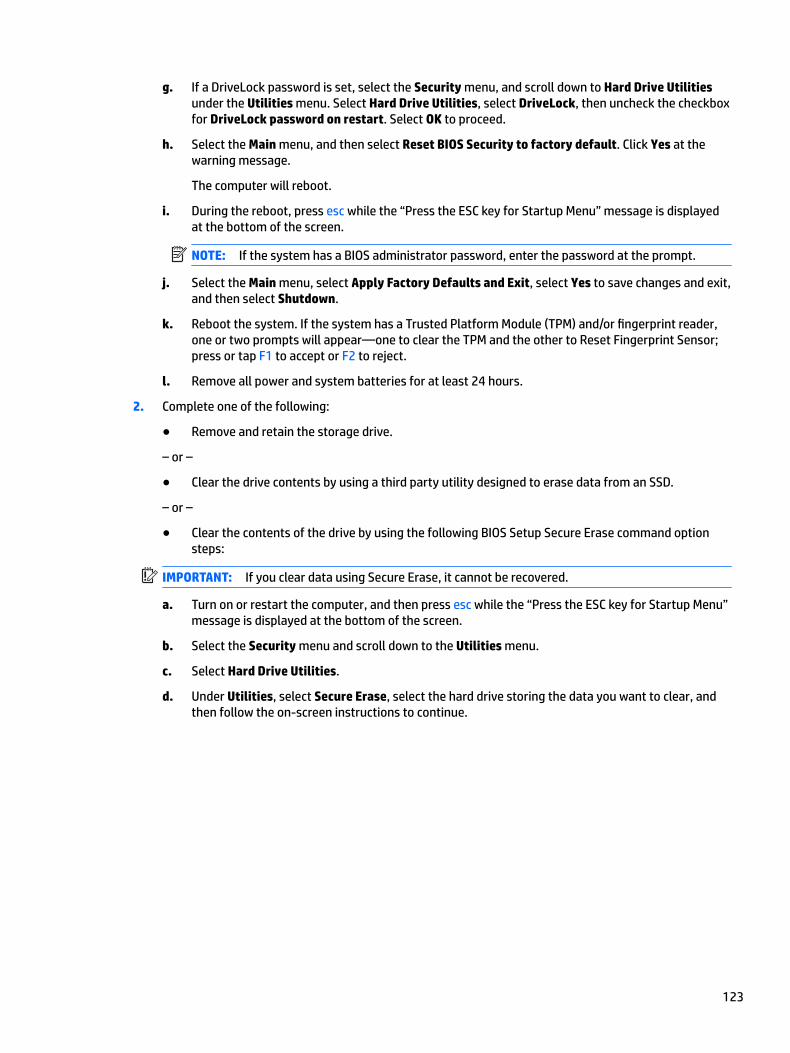
g. If a DriveLock password is set, select the Security menu, and scroll down to Hard Drive Utilities under the Utilities menu. Select Hard Drive Utilities, select DriveLock, then uncheck the checkbox for DriveLock password on restart. Select OK to proceed.
h. Select the Main menu, and then select Reset BIOS Security to factory default. Click Yes at the warning message.
The computer will reboot.
i. During the reboot, press esc while the “Press the ESC key for Startup Menu” message is displayed at the bottom of the screen.
NOTE: If the system has a BIOS administrator password, enter the password at the prompt.
j. Select the Main menu, select Apply Factory Defaults and Exit, select Yes to save changes and exit, and then select Shutdown.
k. Reboot the system. If the system has a Trusted Platform Module (TPM) and/or fingerprint reader, one or two prompts will appear—one to clear the TPM and the other to Reset Fingerprint Sensor; press or tap F1 to accept or F2 to reject.
l. Remove all power and system batteries for at least 24 hours.
2. Complete one of the following:
● Remove and retain the storage drive.
– or –
● Clear the drive contents by using a third party utility designed to erase data from an SSD.
– or –
● Clear the contents of the drive by using the following BIOS Setup Secure Erase command option steps:
IMPORTANT: If you clear data using Secure Erase, it cannot be recovered.
a. Turn on or restart the computer, and then press esc while the “Press the ESC key for Startup Menu” message is displayed at the bottom of the screen.
b. Select the Security menu and scroll down to the Utilities menu.
c. Select Hard Drive Utilities.
d. Under Utilities, select Secure Erase, select the hard drive storing the data you want to clear, and then follow the on-screen instructions to continue.
123
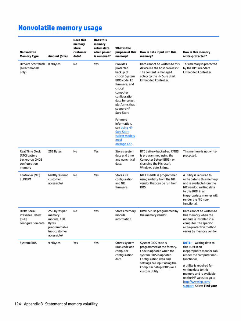
Nonvolatile memory usage
Nonvolatile Memory Type Amount (Size)
Does this memory store customer data?
Does this memory retain data when power is removed?
What is the purpose of this memory?
How is data input into this memory?
How is this memory write-protected?
HP Sure Start flash (select models only)
8 MBytes No Yes Provides protected backup of critical System BIOS code, EC firmware, and critical computer configuration data for select platforms that support HP Sure Start.
For more information, see Using HP Sure Start (select models only) on page 127.
Data cannot be written to this device via the host processor. The content is managed solely by the HP Sure Start Embedded Controller.
This memory is protected by the HP Sure Start Embedded Controller.
Real Time Clock (RTC) battery backed-up CMOS configuration memory
256 Bytes No Yes Stores system date and time and noncritical data.
RTC battery backed-up CMOS is programmed using the Computer Setup (BIOS), or changing the Microsoft Windows date & time.
This memory is not write-protected.
Controller (NIC) EEPROM
64 KBytes (not customer accessible)
No Yes Stores NIC configuration and NIC firmware.
NIC EEPROM is programmed using a utility from the NIC vendor that can be run from DOS.
A utility is required to write data to this memory and is available from the NIC vendor. Writing data to this ROM in an inappropriate manner will render the NIC non-functional.
DIMM Serial Presence Detect (SPD) configuration data
256 Bytes per memory module, 128 Bytes programmable (not customer accessible)
No Yes Stores memory module information.
DIMM SPD is programmed by the memory vendor.
Data cannot be written to this memory when the module is installed in a computer. The specific write-protection method varies by memory vendor.
System BIOS 9 MBytes Yes Yes Stores system BIOS code and computer configuration data.
System BIOS code is programmed at the factory. Code is updated when the system BIOS is updated. Configuration data and settings are input using the Computer Setup (BIOS) or a custom utility.
NOTE: Writing data to this ROM in an inappropriate manner can render the computer non-functional.
A utility is required for writing data to this memory and is available on the HP website; go to http://www.hp.com/support. Select Find your
124 Appendix B Statement of memory volatility
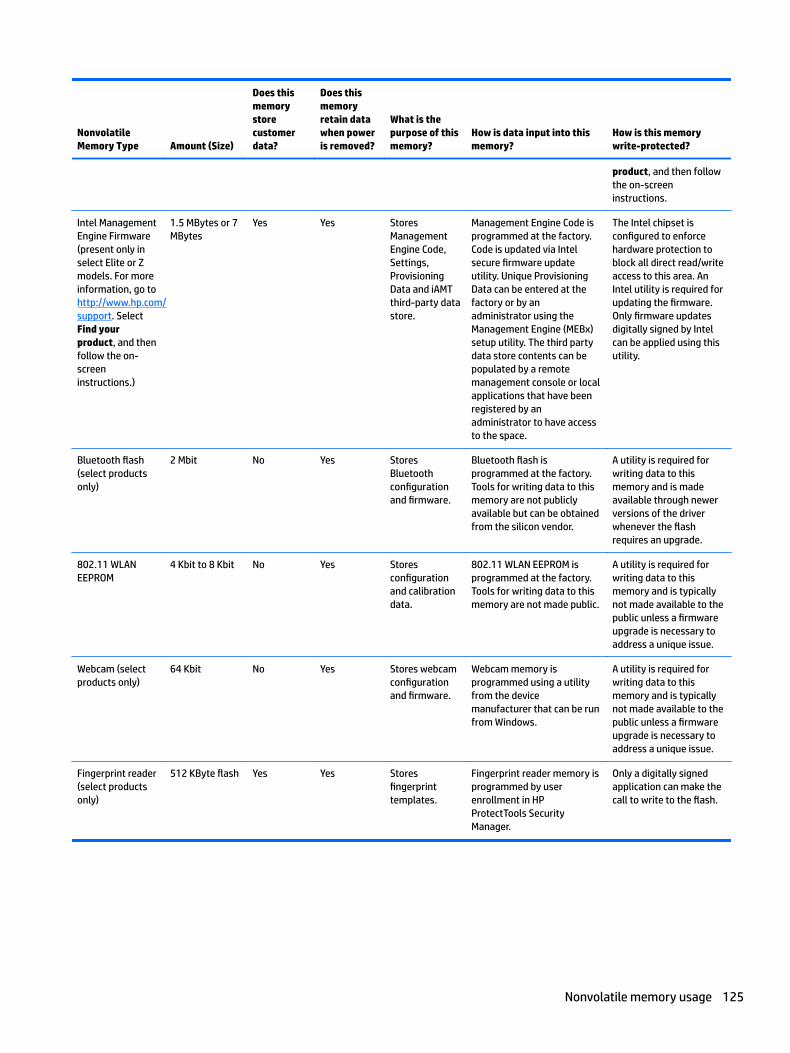
Nonvolatile Memory Type Amount (Size)
Does this memory store customer data?
Does this memory retain data when power is removed?
What is the purpose of this memory?
How is data input into this memory?
How is this memory write-protected?
product, and then follow the on-screen instructions.
Intel Management Engine Firmware (present only in select Elite or Z models. For more information, go to http://www.hp.com/support. Select Find your product, and then follow the on-screen instructions.)
1.5 MBytes or 7 MBytes
Yes Yes Stores Management Engine Code, Settings, Provisioning Data and iAMT third-party data store.
Management Engine Code is programmed at the factory. Code is updated via Intel secure firmware update utility. Unique Provisioning Data can be entered at the factory or by an administrator using the Management Engine (MEBx) setup utility. The third party data store contents can be populated by a remote management console or local applications that have been registered by an administrator to have access to the space.
The Intel chipset is configured to enforce hardware protection to block all direct read/write access to this area. An Intel utility is required for updating the firmware. Only firmware updates digitally signed by Intel can be applied using this utility.
Bluetooth flash (select products only)
2 Mbit No Yes Stores Bluetooth configuration and firmware.
Bluetooth flash is programmed at the factory. Tools for writing data to this memory are not publicly available but can be obtained from the silicon vendor.
A utility is required for writing data to this memory and is made available through newer versions of the driver whenever the flash requires an upgrade.
802.11 WLAN EEPROM
4 Kbit to 8 Kbit No Yes Stores configuration and calibration data.
802.11 WLAN EEPROM is programmed at the factory. Tools for writing data to this memory are not made public.
A utility is required for writing data to this memory and is typically not made available to the public unless a firmware upgrade is necessary to address a unique issue.
Webcam (select products only)
64 Kbit No Yes Stores webcam configuration and firmware.
Webcam memory is programmed using a utility from the device manufacturer that can be run from Windows.
A utility is required for writing data to this memory and is typically not made available to the public unless a firmware upgrade is necessary to address a unique issue.
Fingerprint reader (select products only)
512 KByte flash Yes Yes Stores fingerprint templates.
Fingerprint reader memory is programmed by user enrollment in HP ProtectTools Security Manager.
Only a digitally signed application can make the call to write to the flash.
Nonvolatile memory usage 125
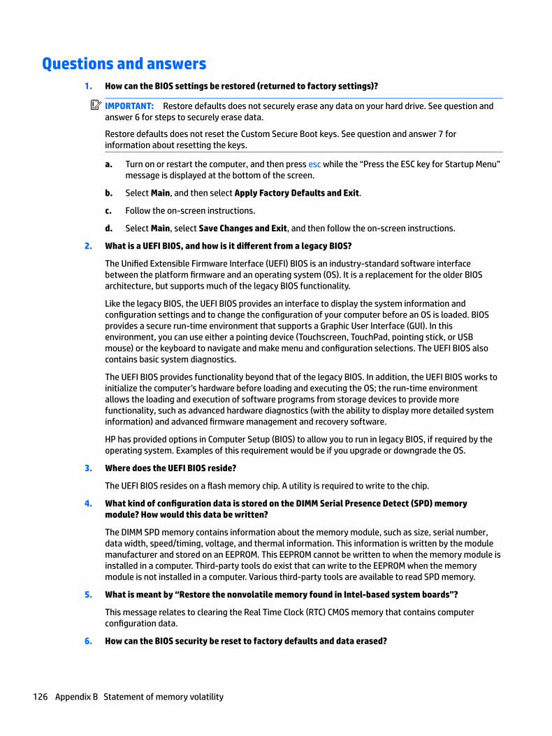
Questions and answers1. How can the BIOS settings be restored (returned to factory settings)?
IMPORTANT: Restore defaults does not securely erase any data on your hard drive. See question and answer 6 for steps to securely erase data.
Restore defaults does not reset the Custom Secure Boot keys. See question and answer 7 for information about resetting the keys.
a. Turn on or restart the computer, and then press esc while the “Press the ESC key for Startup Menu” message is displayed at the bottom of the screen.
b. Select Main, and then select Apply Factory Defaults and Exit.
c. Follow the on-screen instructions.
d. Select Main, select Save Changes and Exit, and then follow the on-screen instructions.
2. What is a UEFI BIOS, and how is it different from a legacy BIOS?
The Unified Extensible Firmware Interface (UEFI) BIOS is an industry-standard software interface between the platform firmware and an operating system (OS). It is a replacement for the older BIOS architecture, but supports much of the legacy BIOS functionality.
Like the legacy BIOS, the UEFI BIOS provides an interface to display the system information and configuration settings and to change the configuration of your computer before an OS is loaded. BIOS provides a secure run-time environment that supports a Graphic User Interface (GUI). In this environment, you can use either a pointing device (Touchscreen, TouchPad, pointing stick, or USB mouse) or the keyboard to navigate and make menu and configuration selections. The UEFI BIOS also contains basic system diagnostics.
The UEFI BIOS provides functionality beyond that of the legacy BIOS. In addition, the UEFI BIOS works to initialize the computer’s hardware before loading and executing the OS; the run-time environment allows the loading and execution of software programs from storage devices to provide more functionality, such as advanced hardware diagnostics (with the ability to display more detailed system information) and advanced firmware management and recovery software.
HP has provided options in Computer Setup (BIOS) to allow you to run in legacy BIOS, if required by the operating system. Examples of this requirement would be if you upgrade or downgrade the OS.
3. Where does the UEFI BIOS reside?
The UEFI BIOS resides on a flash memory chip. A utility is required to write to the chip.
4. What kind of configuration data is stored on the DIMM Serial Presence Detect (SPD) memory module? How would this data be written?
The DIMM SPD memory contains information about the memory module, such as size, serial number, data width, speed/timing, voltage, and thermal information. This information is written by the module manufacturer and stored on an EEPROM. This EEPROM cannot be written to when the memory module is installed in a computer. Third-party tools do exist that can write to the EEPROM when the memory module is not installed in a computer. Various third-party tools are available to read SPD memory.
5. What is meant by “Restore the nonvolatile memory found in Intel-based system boards”?
This message relates to clearing the Real Time Clock (RTC) CMOS memory that contains computer configuration data.
6. How can the BIOS security be reset to factory defaults and data erased?
126 Appendix B Statement of memory volatility
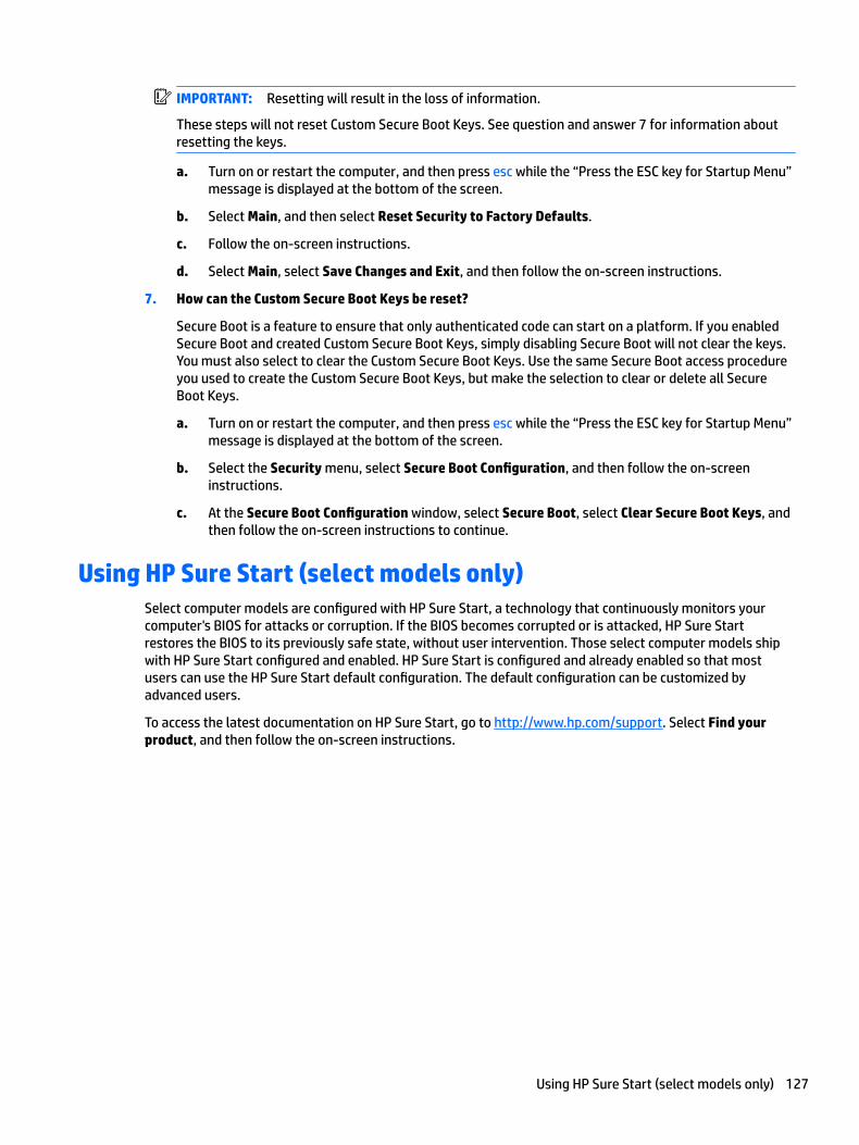
IMPORTANT: Resetting will result in the loss of information.
These steps will not reset Custom Secure Boot Keys. See question and answer 7 for information about resetting the keys.
a. Turn on or restart the computer, and then press esc while the “Press the ESC key for Startup Menu” message is displayed at the bottom of the screen.
b. Select Main, and then select Reset Security to Factory Defaults.
c. Follow the on-screen instructions.
d. Select Main, select Save Changes and Exit, and then follow the on-screen instructions.
7. How can the Custom Secure Boot Keys be reset?
Secure Boot is a feature to ensure that only authenticated code can start on a platform. If you enabled Secure Boot and created Custom Secure Boot Keys, simply disabling Secure Boot will not clear the keys. You must also select to clear the Custom Secure Boot Keys. Use the same Secure Boot access procedure you used to create the Custom Secure Boot Keys, but make the selection to clear or delete all Secure Boot Keys.
a. Turn on or restart the computer, and then press esc while the “Press the ESC key for Startup Menu” message is displayed at the bottom of the screen.
b. Select the Security menu, select Secure Boot Configuration, and then follow the on-screen instructions.
c. At the Secure Boot Configuration window, select Secure Boot, select Clear Secure Boot Keys, and then follow the on-screen instructions to continue.
Using HP Sure Start (select models only)Select computer models are configured with HP Sure Start, a technology that continuously monitors your computer's BIOS for attacks or corruption. If the BIOS becomes corrupted or is attacked, HP Sure Start restores the BIOS to its previously safe state, without user intervention. Those select computer models ship with HP Sure Start configured and enabled. HP Sure Start is configured and already enabled so that most users can use the HP Sure Start default configuration. The default configuration can be customized by advanced users.
To access the latest documentation on HP Sure Start, go to http://www.hp.com/support. Select Find your product, and then follow the on-screen instructions.
Using HP Sure Start (select models only) 127
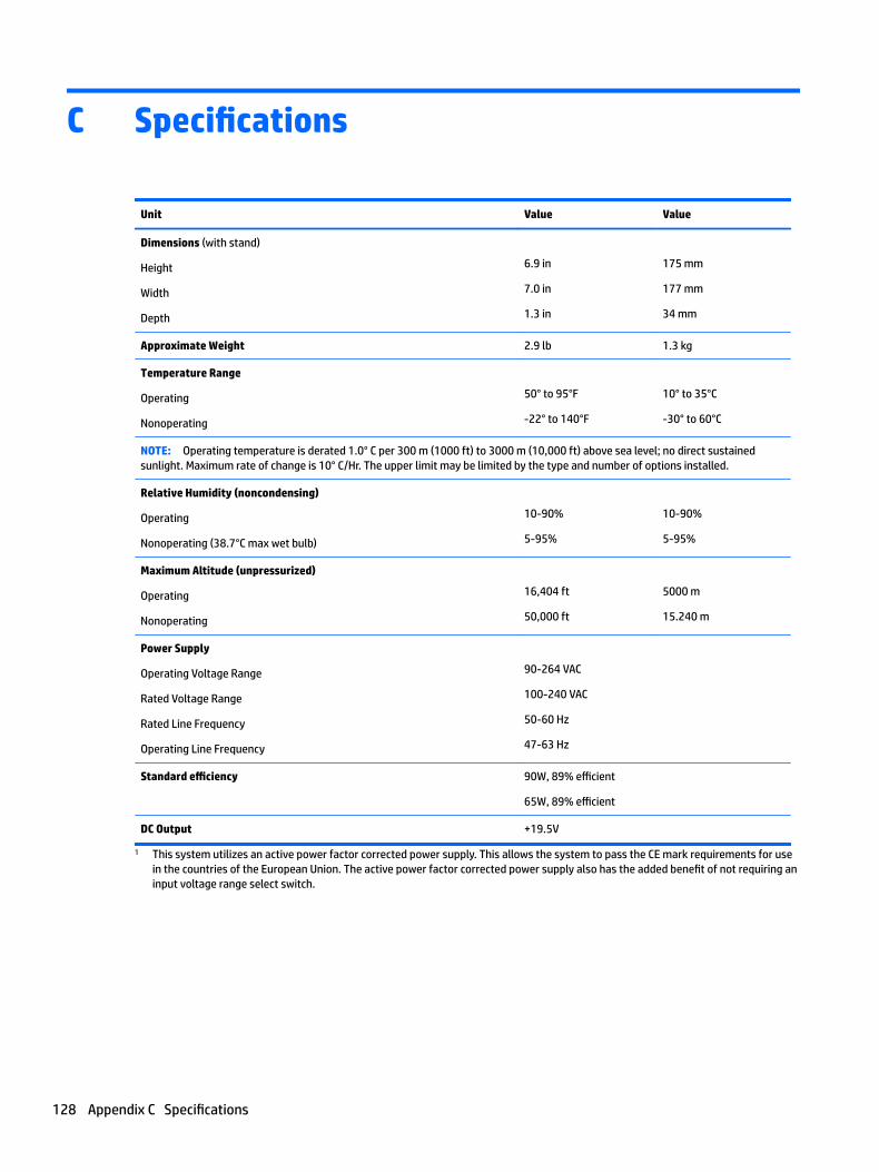
C Specifications
Unit Value Value
Dimensions (with stand)
Height
Width
Depth
6.9 in
7.0 in
1.3 in
175 mm
177 mm
34 mm
Approximate Weight 2.9 lb 1.3 kg
Temperature Range
Operating
Nonoperating
50° to 95°F
-22° to 140°F
10° to 35°C
-30° to 60°C
NOTE: Operating temperature is derated 1.0° C per 300 m (1000 ft) to 3000 m (10,000 ft) above sea level; no direct sustained sunlight. Maximum rate of change is 10° C/Hr. The upper limit may be limited by the type and number of options installed.
Relative Humidity (noncondensing)
Operating
Nonoperating (38.7°C max wet bulb)
10-90%
5-95%
10-90%
5-95%
Maximum Altitude (unpressurized)
Operating
Nonoperating
16,404 ft
50,000 ft
5000 m
15.240 m
Power Supply
Operating Voltage Range
Rated Voltage Range
Rated Line Frequency
Operating Line Frequency
90-264 VAC
100-240 VAC
50-60 Hz
47-63 Hz
Standard efficiency 90W, 89% efficient
65W, 89% efficient
DC Output +19.5V
1 This system utilizes an active power factor corrected power supply. This allows the system to pass the CE mark requirements for use in the countries of the European Union. The active power factor corrected power supply also has the added benefit of not requiring an input voltage range select switch.
128 Appendix C Specifications
Index
Aaccess panel
locked 72administrator password 104antenna (external)
removal and replacement 38antenna connector, external 3, 4antenna cover 3, 4audible codes 102audio problems 83audio-out (headset)/audio-in
(microphone) combo jack 1, 2
Bbackup and recovery, Windows 7
109Backup and Restore, Windows 7
112backups
creating Windows 7 109, 111battery
disposal 17removal and replacement 40
battery replacement 40beep codes 102bezel
illustrated 6BIOS
clearing and resetting 106booting options
Full Boot 97Quick Boot 97
buttonspower 1, 2
Ccable management 19cable pinouts, SATA data 18cautions
AC power 12cables 17electrostatic discharge 12keyboard cleaning 15keyboard keys 16
cleaningcomputer 15mouse 16safety precautions 15
CMOSbacking up 104
computerspecifications 128
computer cleaning 15Computer Setup
access problem 71connectors
external antenna 3, 4power 3, 4
country power cord set requirements 121
cover lock switch 3Customer Support 69
Ddisassembly preparation 20DisplayPort 3, 4DisplayPort option board
illustrated 9drive cage
removal and replacement 33drive light 1, 2Driver Recovery DVD,
creating 111using for restore 114
Dual-Mode DisplayPort 3, 4dust filter 23
Eelectrostatic discharge (ESD) 12
preventing damage 13error
codes 97, 102messages 97
external antennaremoval and replacement 38
FF10 Setup
access problem 71
fanillustrated 9removal and replacement 32, 42
fan ductillustrated 9
flash drive problems 93flashing LEDs 102front bezel
removal and replacement 22front panel components 1
EliteDesk 800 1ProDesk 400 2ProDesk 600 1
front panel problems 94
Ggeneral problems 71grounding methods 13
Hhard drive
installation 29proper handling 17removal 29removal and replacement 29SATA characteristics 18
hard drive cableremoval and replacement 31
hard drive problems 76hard drive recovery
Windows 7 112hardware installation problems 87HDMI option board
illustrated 9headphone jack 1, 2heat sink
illustrated 9removal and replacement 43, 46
Help and SupportWindows 7 109
helpful hints 70HP PC Hardware Diagnostics (UEFI)
using 107HP Recovery Disc Creator, using 111HP Sure Start 127
Index 129

Iinstalling
battery 40dust filter 23hard drive 29memory 25solid state drive 34
Internet access problems 94
Jjacks
audio-out (headset)/audio-in (microphone) combo 1, 2
headphone 1, 2RJ-45 (network) 3, 4
Kkeyboard
cleaning 15keyboard problems 86
Llights
drive 1, 2
Mmedia card reader
problems 78memory
installation 25maximum 25nonvolatile 122problems 92removal and replacement 27slots 25socket population 26SODIMMs specifications 25specifications 25volatile 122
memory modulesillustrated 7
monitor problems 79mouse
cleaning 16problems 86
Nnetwork problems 89nonvolatile memory 122numeric error codes 97
Ooperating guidelines 14option board
removal and replacement 49option board, DisplayPort
illustrated 9option board, HDMI
illustrated 9option board, serial port
illustrated 9option board, USB Type-C
illustrated 10option board, VGA
illustrated 10overheating, prevention 14
Ppadlock loop 3, 4password
administrator 104clearing 104power-on 104
portsDisplayPort 3, 4Dual-Mode DisplayPort 3, 4HDMI 3, 4serial 3, 4USB 2.0 4USB 3.x 1, 2, 3, 4USB 3.x with HP Sleep and
Charge 1, 2USB Type-C alternate mode 3USB Type-C SuperSpeed with HP
Sleep and Charge 1VGA 3, 4
POST error messages 97power button, dual-state 1, 2power connector 3, 4power cord set requirements
country specific 121power problems 75power supply
illustrated 6operating voltage range 128
power-on password 104printer problems 85problems
audio 83Computer Setup 71F10 Setup 71
flash drive 93front panel 94general 71hard drive 76hardware installation 87Internet access 94keyboard 86Media Card Reader 78memory 92monitor 79mouse 86network 89power 75printer 85software 96
product ID location 5
Rrear panel components
EliteDesk 800 3ProDesk 400 4ProDesk 600 3
recovery discs, steps for creating Windows 7 110
recovery discs, using for restore114
recovery media, creating 111recovery media, creating Windows
7 109recovery USB flash drive, steps for
creating Windows 7 110removal and replacement
antenna (external) 38battery 40drive cage 33external antenna 38fan 32, 42front bezel 22hard drive 29hard drive cable 31heat sink 43, 46memory 27option board 49speaker 48system board 50thermal sensor 24top cover 21WLAN antennas 53WLAN module 36
130 Index
removingbattery 40dust filter 23hard drive 29solid state drive 34
removing personal data from volatile system memory 122
resettingCMOS 104password jumper 104
RJ-45 (network) jack 3, 4
Ssafety and comfort 69safety precautions
cleaning 15SATA
connectors on system board 18data cable pinouts 18hard drive characteristics 18
SATA cableillustrated 8
screws, correct size 16secondary hard drive fan
illustrated 9security cable slot 3, 4serial number location 5serial port 4serial port option board
illustrated 9service considerations 16slots
security cable 3, 4SODIMM
specifications 25software
problems 96servicing computer 16
solid state driveinstallation 34removal 34
speakerillustrated 9removal and replacement 48
specificationscomputer 128
specifications, memory 25static electricity 12system board
illustrated 6
removal and replacement 50SATA connectors 18
system memory, removing personal data from volatile 122
System Recovery using Windows 7 recovery media 114
System Recovery, Windows 7 112system restore points, creating
Windows 7 109System Restore, Windows 7 112
Ttamper-proof screws
tool 16temperature control 14thermal sensor
illustrated 9removal and replacement 24
thumbscrew 4tools, servicing 16top cover
removal and replacement 21Torx T15 screwdriver 16tower conversion 56
UUSB 2.0 ports 4USB 3.x port with HP Sleep and
Charge 1, 2USB 3.x ports 1, 2, 3, 4USB Type-C option board
illustrated 10USB Type-C SuperSpeed port with HP
Sleep and Charge 1
Vventilation, proper 14VGA option board
illustrated 10
WWindows 10
backup and restore 115Windows 7
backing up information 111backup and recovery 109Backup and Restore 112creating backups 109creating recovery media 109creating system restore points
109
hard drive recovery 112Help and Support 109steps for creating recovery
discs 110steps for creating recovery
media 110steps for creating recovery USB flash drive 110
System Recovery 112System Recovery using recovery
media 114System Restore 112
Windows 7 operating system discsusing for restore 114
Windows 7 operating system DVDcreating 111using for restore 114
Windows 7 operating system mediacreating 111
WLAN antennasremoval and replacement 53
WLAN moduleremoval and replacement 36
Index 131