Embed Size (px)
DESCRIPTION
Main Y4 SemII Fiber Optic Communicatio
Citation preview

1
INSTITUTE EXAMINATIONS – ACADEMIC YEAR 2012 - 2013
SEMESTER II MAIN EXAMINATION
FACULTY OF ENGINEERING
ELECTRICAL AND ELECTRONICS ENGINEERING
FOURTH YEAR ETE SEMESTER II (PART-TIME)
EEE 3422 – FIBER OPTIC COMMUNICATION
DATE: ……………..
TIME: 2 HOURS
MAXIMUM MARKS = 60
INSTRUCTIONS
1. This paper contains ONE (1) question in SECTION A and THREE (3) questions in SECTION B 2. Answer
- ALL questions in SECTION A and
- any TWO (2) questions from SECTION B 3. No written materials allowed. 4. Write all your answers in the answer booklet provided. 5. Do not forget to write your Registration Number.
6. Do not write any answers on this question paper.
KIGALI INSTITUTE OF SCIENCE AND TECHNOLOGY
INSTITUT DES SCIENCES ET TECHNOLOGIE
Avenue de l'Armée, B.P. 3900 Kigali, Rwanda
Reg. No:…………………………….

2
SECTION A (Compulsory)
Question 1 (20 Marks)
a) State three disadvantages of Optical Fiber Communications. (3 marks)
b) Give 2 examples of dopants which:
(i) Increase the refractive index of the core (1 example). (1 mark)
(ii) Decrease the refractive index of the cladding (1 example). (1 mark)
c) Compare a single-mode step index fibers and multimode step index fibers while used as an
optical channel. (5 marks)
d) Compare the light emitted from LASERs and LEDS. (2 marks)
e) With the aid of a block diagram, discuss the function of the major elements of an optical fiber
transmitter. (4 marks)
f) Design a bus optical network topology and explain its working principle. (4 marks)
SECTION B (Attempt any two questions)
Question 2 (20 Marks)
a) Using simple ray theory, design a mechanism for the transmission of light within an optical
fiber. Briefly discuss with the aid of a suitable diagram what is meant by the acceptance angle for
an optical fiber. Show how this is related to the fiber numerical aperture and the refractive
indices for the fiber core and cladding. (5 marks)
b) Briefly describe the two processes by which light can be emitted from an atom. Discuss the
requirement for population inversion in order that stimulated emission may dominate over
spontaneous emission. Illustrate your answer with an energy level diagram. (7 marks)
c) Derive the expression for the output photocurrent of a basic coherent detector in both
heterodyne and homodyne detection. (8 marks)

3
Question 3 (20 Marks)
a) Discuss the mechanism of optical feedback to provide oscillation and hence amplification
within the laser. (4 marks)
b) A D-IM analog optical fiber link of length 2 Km employs an LED which launches mean
optical power of 10 dBm into a multimode optical fiber. The fiber cable exhibits a loss of 3.5
with splice losses calculated at 0.7 In addition, there is a connector loss at the
receiver of 1.6 dB. The p-i-n photodiode receiver has a sensitivity of 25 dBm for an SNR of 50
dB and with a modulation index of 0.5. It is estimated that a safety margin of 4 dB is required.
Assuming there is no dispersion-equalization penalty:
(i) Perform an optical power budget for the system operating under the above conditions and
ascertain its viability.
(ii) Estimate any possible increase in link length which may be achieved using an injection laser
source which launches mean optical power of 0 dBm into the fiber cable. In this case, the safety
margin must be increased to 7 dB. (8 marks)
c) Compare orthogonal frequency division multiplexing (OFDM) with conventional frequency
division multiplexing (FDM). (8 marks)
Question 4 (20 Marks)
a) Derive an expression for the coupling efficiency of a surface-emitting LED into a step index
fiber, assuming the device to have a Lambertian output. Determine the optical loss in decibels
when coupling the optical power emitted from the device into a step index fiber with an
acceptance angle of 14°. It may be assumed that the LED is smaller than the fiber core and that
the two are in close proximity. (10 marks)
b) Explain the Four-channel OTDM fiber system. (10 marks)

4
MARKING SCHEME
Question 1
a) State three disadvantages of Optical Fiber Communications. (3 marks)
b) Give 2 examples of dopants which:
(i) Increase the refractive index of the core (1 example). (1 mark)
(ii) Decrease the refractive index of the cladding (1 example). (1 mark)
c) Compare a single-mode step index fibers and multimode step index fibers while used as an
optical channel. (5 marks)
d) Compare the light emitted from LASERs and LEDS. (2 marks)
e) With the aid of a block diagram, discuss the function of the major elements of an optical fiber
transmitter. (4 marks)
f) Design a bus optical network topology and explain its working principle. (4 marks)
Solution 1
a) Disadvantages of Optical Fiber Communications
(3 marks)
b) (i) Dopants such as GeO2 and P2O5 increase the refractive index of silica and are suitable for
the core. (1 mark)
(ii) Dopants such as B2O3 and fluorine decrease the refractive index of silica and are suitable for
the cladding. (1 mark)
5
c) The single-mode step index fiber has the distinct advantage of low intermodal dispersion
(broadening of transmitted light pulses), as only one mode is transmitted, whereas with
multimode step index fiber considerable dispersion may occur due to the differing group
velocities of the propagating modes. This in turn restricts the maximum bandwidth attainable
with multimode step index fibers, especially when compared with single-mode fibers.
(2 marks)
However, for lower bandwidth applications multimode fibers have several advantages over
single-mode fibers. These are:
(i) The use of spatially incoherent optical sources (e.g. most light-emitting diodes) which cannot
be efficiently coupled to single-mode fibers;
(ii) Larger numerical apertures, as well as core diameters, facilitating easier coupling to optical
sources;
(iii) Lower tolerance requirements on fiber connectors.
(3 marks)
d) A laser emits a relatively narrow angular spread of Light while a LED transmits light within a
relatively wide cone (2 marks)
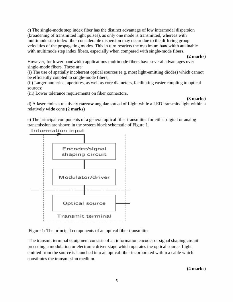
e) The principal components of a general optical fiber transmitter for either digital or analog
transmission are shown in the system block schematic of Figure 1.
Figure 1: The principal components of an optical fiber transmitter
The transmit terminal equipment consists of an information encoder or signal shaping circuit
preceding a modulation or electronic driver stage which operates the optical source. Light
emitted from the source is launched into an optical fiber incorporated within a cable which
constitutes the transmission medium.
(4 marks)
6
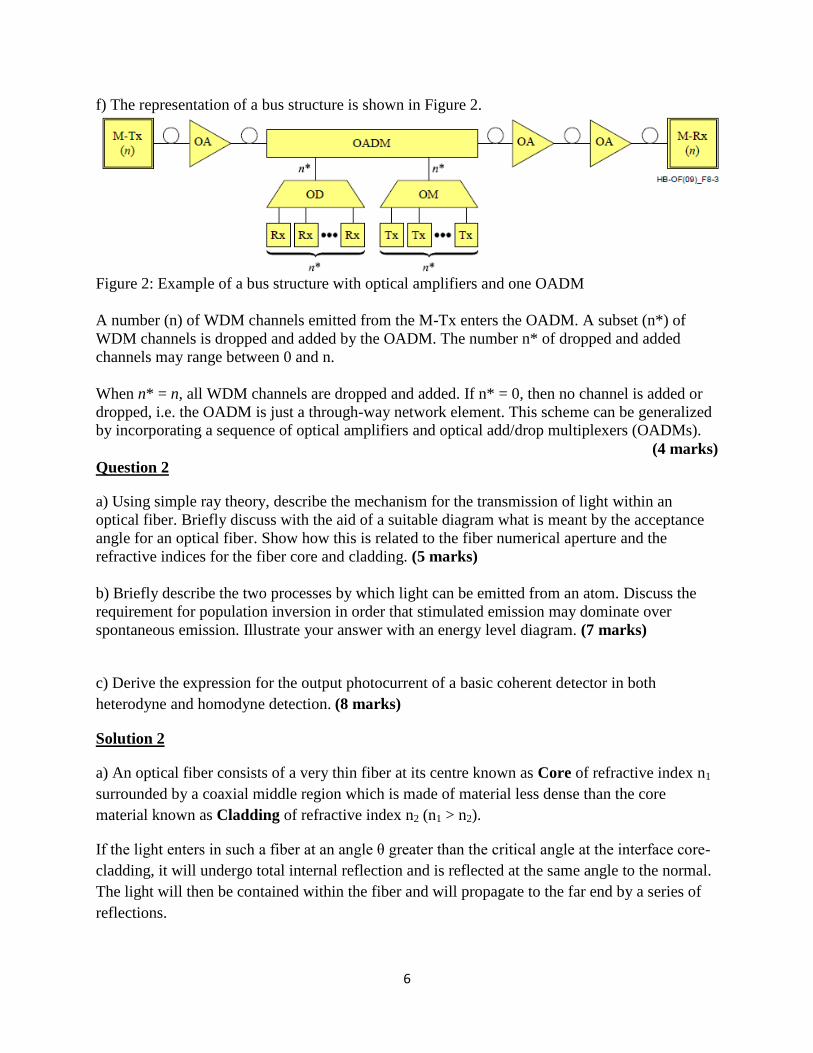
f) The representation of a bus structure is shown in Figure 2.
Figure 2: Example of a bus structure with optical amplifiers and one OADM
A number (n) of WDM channels emitted from the M-Tx enters the OADM. A subset (n*) of
WDM channels is dropped and added by the OADM. The number n* of dropped and added
channels may range between 0 and n.
When n* = n, all WDM channels are dropped and added. If n* = 0, then no channel is added or
dropped, i.e. the OADM is just a through-way network element. This scheme can be generalized
by incorporating a sequence of optical amplifiers and optical add/drop multiplexers (OADMs).
(4 marks)
Question 2
a) Using simple ray theory, describe the mechanism for the transmission of light within an
optical fiber. Briefly discuss with the aid of a suitable diagram what is meant by the acceptance
angle for an optical fiber. Show how this is related to the fiber numerical aperture and the
refractive indices for the fiber core and cladding. (5 marks)
b) Briefly describe the two processes by which light can be emitted from an atom. Discuss the
requirement for population inversion in order that stimulated emission may dominate over
spontaneous emission. Illustrate your answer with an energy level diagram. (7 marks)
c) Derive the expression for the output photocurrent of a basic coherent detector in both
heterodyne and homodyne detection. (8 marks)
Solution 2
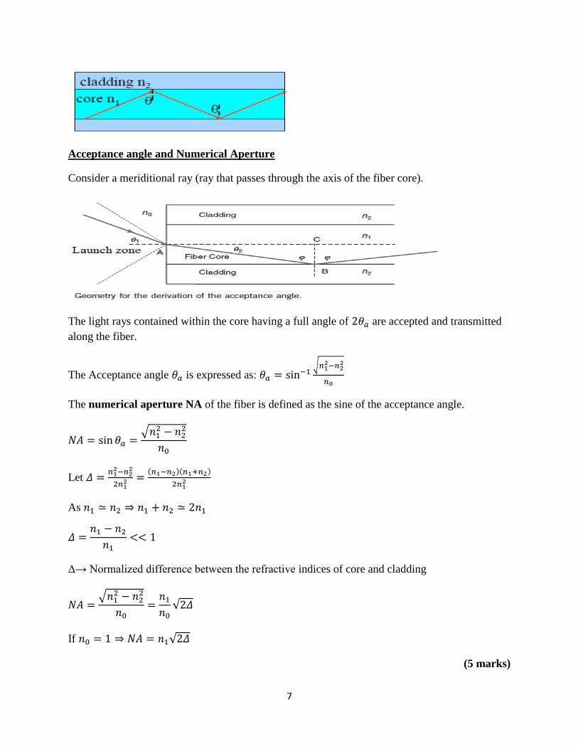
a) An optical fiber consists of a very thin fiber at its centre known as Core of refractive index n1
surrounded by a coaxial middle region which is made of material less dense than the core
material known as Cladding of refractive index n2 (n1 > n2).
If the light enters in such a fiber at an angle θ greater than the critical angle at the interface core-
cladding, it will undergo total internal reflection and is reflected at the same angle to the normal.
The light will then be contained within the fiber and will propagate to the far end by a series of
reflections.
7
Acceptance angle and Numerical Aperture
Consider a meriditional ray (ray that passes through the axis of the fiber core).
The light rays contained within the core having a full angle of are accepted and transmitted
along the fiber.
The Acceptance angle is expressed as:
√
The numerical aperture NA of the fiber is defined as the sine of the acceptance angle.
√
Let
( )( )
As
Δ→ Normalized difference between the refractive indices of core and cladding
√
√
If √
(5 marks)
8
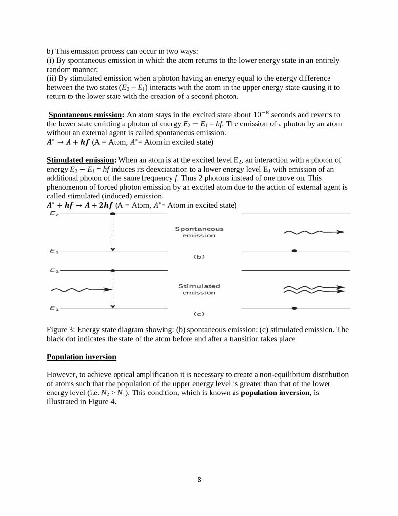
b) This emission process can occur in two ways:
(i) By spontaneous emission in which the atom returns to the lower energy state in an entirely
random manner;
(ii) By stimulated emission when a photon having an energy equal to the energy difference
between the two states (E2 − E1) interacts with the atom in the upper energy state causing it to
return to the lower state with the creation of a second photon.
Spontaneous emission: An atom stays in the excited state about seconds and reverts to
the lower state emitting a photon of energy E2 E1 = hf. The emission of a photon by an atom
without an external agent is called spontaneous emission.
(A = Atom, = Atom in excited state)
Stimulated emission: When an atom is at the excited level E2, an interaction with a photon of
energy E2 E1 = hf induces its deexciatation to a lower energy level E1 with emission of an
additional photon of the same frequency f. Thus 2 photons instead of one move on. This
phenomenon of forced photon emission by an excited atom due to the action of external agent is
called stimulated (induced) emission.
(A = Atom, = Atom in excited state)
Figure 3: Energy state diagram showing: (b) spontaneous emission; (c) stimulated emission. The
black dot indicates the state of the atom before and after a transition takes place
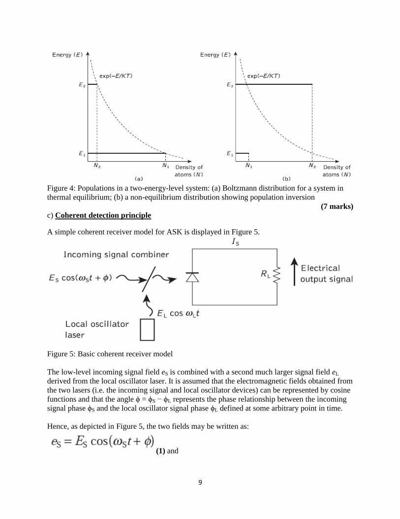
Population inversion
However, to achieve optical amplification it is necessary to create a non-equilibrium distribution
of atoms such that the population of the upper energy level is greater than that of the lower
energy level (i.e. N2 > N1). This condition, which is known as population inversion, is
illustrated in Figure 4.
9
Figure 4: Populations in a two-energy-level system: (a) Boltzmann distribution for a system in
thermal equilibrium; (b) a non-equilibrium distribution showing population inversion
(7 marks) c) Coherent detection principle
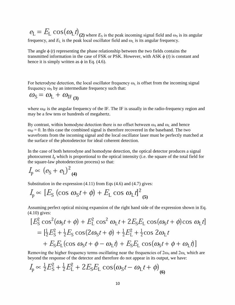
A simple coherent receiver model for ASK is displayed in Figure 5.
Figure 5: Basic coherent receiver model
The low-level incoming signal field eS is combined with a second much larger signal field eL
derived from the local oscillator laser. It is assumed that the electromagnetic fields obtained from
the two lasers (i.e. the incoming signal and local oscillator devices) can be represented by cosine
functions and that the angle ϕ = ϕS − ϕL represents the phase relationship between the incoming
signal phase ϕS and the local oscillator signal phase ϕL defined at some arbitrary point in time.
Hence, as depicted in Figure 5, the two fields may be written as:
(1) and
10
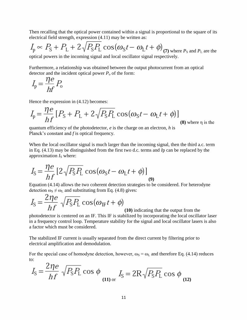
(2) where ES is the peak incoming signal field and ωS is its angular
frequency, and EL is the peak local oscillator field and ωL is its angular frequency.
The angle ϕ (t) representing the phase relationship between the two fields contains the
transmitted information in the case of FSK or PSK. However, with ASK ϕ (t) is constant and
hence it is simply written as ϕ in Eq. (4.6).
For heterodyne detection, the local oscillator frequency ωL is offset from the incoming signal
frequency ωS by an intermediate frequency such that:
(3)
where ωIF is the angular frequency of the IF. The IF is usually in the radio-frequency region and
may be a few tens or hundreds of megahertz.
By contrast, within homodyne detection there is no offset between ωS and ωL and hence
ωIF = 0. In this case the combined signal is therefore recovered in the baseband. The two
wavefronts from the incoming signal and the local oscillator laser must be perfectly matched at
the surface of the photodetector for ideal coherent detection.
In the case of both heterodyne and homodyne detection, the optical detector produces a signal
photocurrent Ip which is proportional to the optical intensity (i.e. the square of the total field for
the square-law photodetection process) so that:
(4)
Substitution in the expression (4.11) from Eqs (4.6) and (4.7) gives:
(5)
Assuming perfect optical mixing expansion of the right hand side of the expression shown in Eq.
(4.10) gives:
Removing the higher frequency terms oscillating near the frequencies of 2ωS and 2ωL which are
beyond the response of the detector and therefore do not appear in its output, we have:
(6)
11
Then recalling that the optical power contained within a signal is proportional to the square of its
electrical field strength, expression (4.11) may be written as:
(7) where PS and PL are the
optical powers in the incoming signal and local oscillator signal respectively.
Furthermore, a relationship was obtained between the output photocurrent from an optical
detector and the incident optical power Po of the form:
Hence the expression in (4.12) becomes:
(8) where η is the
quantum efficiency of the photodetector, e is the charge on an electron, h is
Planck’s constant and f is optical frequency.
When the local oscillator signal is much larger than the incoming signal, then the third a.c. term
in Eq. (4.13) may be distinguished from the first two d.c. terms and Ip can be replaced by the
approximation IS where:
(9)
Equation (4.14) allows the two coherent detection strategies to be considered. For heterodyne
detection ωS ≠ ωL and substituting from Eq. (4.8) gives:
(10) indicating that the output from the
photodetector is centered on an IF. This IF is stabilized by incorporating the local oscillator laser
in a frequency control loop. Temperature stability for the signal and local oscillator lasers is also
a factor which must be considered.
The stabilized IF current is usually separated from the direct current by filtering prior to
electrical amplification and demodulation.
For the special case of homodyne detection, however, ωS = ωL and therefore Eq. (4.14) reduces
to:
(11) or (12)

12
where R is the responsivity of the optical detector. In this case the output from the photodiode is
in the baseband and the local oscillator laser needs to be phase locked to the incoming optical
signal.
(8 marks)
Question 3
a) Discuss the mechanism of optical feedback to provide oscillation and hence amplification
within the laser. (4 marks)
b) A D-IM analog optical fiber link of length 2 Km employs an LED which launches mean
optical power of 10 dBm into a multimode optical fiber. The fiber cable exhibits a loss of 3.5
with splice losses calculated at 0.7 In addition, there is a connector loss at the
receiver of 1.6 dB. The p-i-n photodiode receiver has a sensitivity of 25 dBm for an SNR of 50
dB and with a modulation index of 0.5. It is estimated that a safety margin of 4 dB and with a
modulation index of 0.5. It is estimated that a safety margin of 4 dB is required. Assuming there
is no dispersion-equalization penalty:
(i) Perform an optical power budget for the system operating under the above conditions and
ascertain its viability.
(ii) Estimate any possible increase in link length which may be achieved using an injection laser
source which launches mean optical power of 0 dBm into the fiber cable. In this case, the safety
margin must be increased to 7 dB. (8 marks)
c) Compare orthogonal frequency division multiplexing (OFDM) with conventional frequency
division multiplexing (FDM). (8 marks)
Solution 3
a) Optical feedback
To achieve this laser action, it is necessary to contain photons within the laser medium and
maintain the conditions for coherence. This is accomplished by placing or forming mirrors (plane
or curved) at either end of the amplifying medium, as illustrated in Figure 6.
Figure 6: The basic laser structure incorporating plane mirrors
13
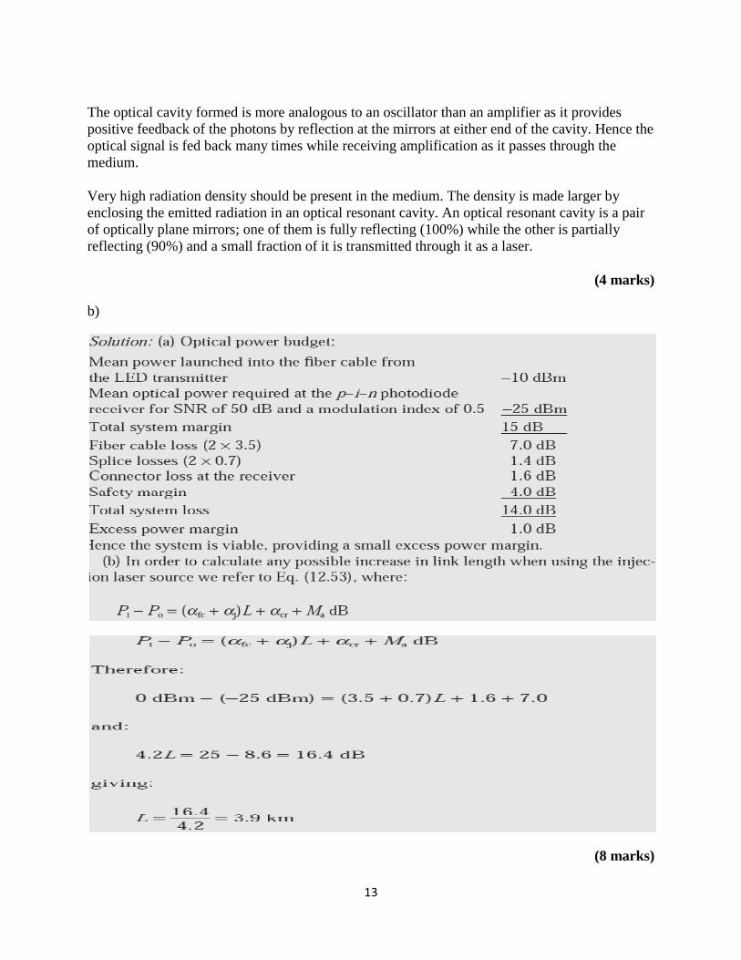
The optical cavity formed is more analogous to an oscillator than an amplifier as it provides
positive feedback of the photons by reflection at the mirrors at either end of the cavity. Hence the
optical signal is fed back many times while receiving amplification as it passes through the
medium.
Very high radiation density should be present in the medium. The density is made larger by
enclosing the emitted radiation in an optical resonant cavity. An optical resonant cavity is a pair
of optically plane mirrors; one of them is fully reflecting (100%) while the other is partially
reflecting (90%) and a small fraction of it is transmitted through it as a laser.
(4 marks)
b)
(8 marks)
14
c) Orthogonal frequency division multiplexing (OFDM) is a multicarrier transmission technique
which is based on frequency division multiplexing (FDM). In conventional FDM, multiple-
frequency signals are transmitted simultaneously in parallel where the data contained in each
signal is modulated onto subcarriers and therefore the subcarrier multiplexed signal typically
contains a wide range of frequencies. Each subcarrier is separated by a guard band to avoid
signal overlapping. The subcarriers are then demodulated at the receiver by using filters to
separate the frequency bands.
By contrast, OFDM employs several subcarrier frequencies orthogonal to each other (i.e.
perpendicular) and therefore they do not overlap. Hence this technique can squeeze multiple
modulated carriers tightly together at a reduced bandwidth without the requirement for guard
bands while at the same time keeping the modulated signals orthogonal so that they do not
interfere with each other, as illustrated in Figure 7.
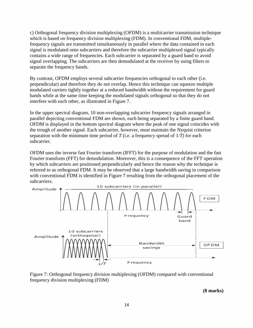
In the upper spectral diagram, 10 non-overlapping subcarrier frequency signals arranged in
parallel depicting conventional FDM are shown, each being separated by a finite guard band.
OFDM is displayed in the bottom spectral diagram where the peak of one signal coincides with
the trough of another signal. Each subcarrier, however, must maintain the Nyquist criterion
separation with the minimum time period of T (i.e. a frequency spread of 1/T) for each
subcarrier.
OFDM uses the inverse fast Fourier transform (IFFT) for the purpose of modulation and the fast
Fourier transform (FFT) for demodulation. Moreover, this is a consequence of the FFT operation
by which subcarriers are positioned perpendicularly and hence the reason why the technique is
referred to as orthogonal FDM. It may be observed that a large bandwidth saving in comparison
with conventional FDM is identified in Figure 7 resulting from the orthogonal placement of the
subcarriers.
Figure 7: Orthogonal frequency division multiplexing (OFDM) compared with conventional
frequency division multiplexing (FDM)
(8 marks)
15
Question 4
a) Derive an expression for the coupling efficiency of a surface-emitting LED into a step index
fiber, assuming the device to have a Lambertian output. Determine the optical loss in decibels
when coupling the optical power emitted from the device into a step index fiber with an
acceptance angle of 14°. It may be assumed that the LED is smaller than the fiber core and that
the two are in close proximity. (10 marks)
b) Explain the Four-channel OTDM fiber system. (10 marks)
Solution 4
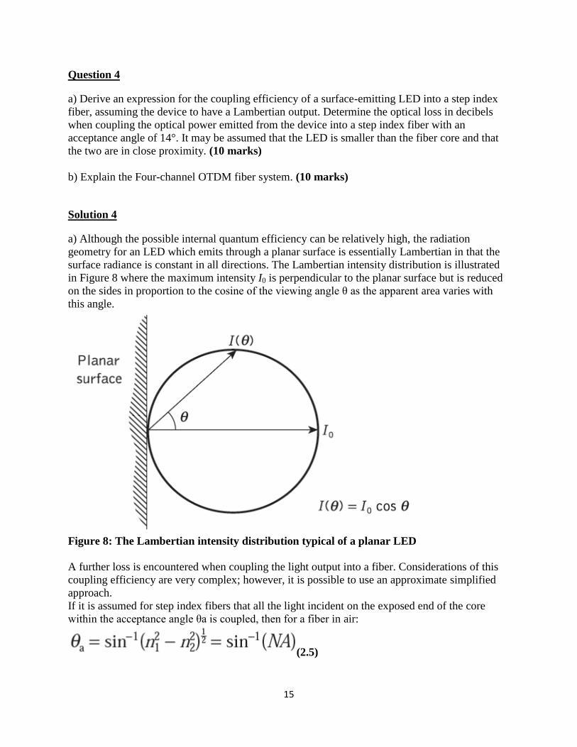
a) Although the possible internal quantum efficiency can be relatively high, the radiation
geometry for an LED which emits through a planar surface is essentially Lambertian in that the
surface radiance is constant in all directions. The Lambertian intensity distribution is illustrated
in Figure 8 where the maximum intensity I0 is perpendicular to the planar surface but is reduced
on the sides in proportion to the cosine of the viewing angle θ as the apparent area varies with
this angle.
Figure 8: The Lambertian intensity distribution typical of a planar LED
A further loss is encountered when coupling the light output into a fiber. Considerations of this
coupling efficiency are very complex; however, it is possible to use an approximate simplified
approach.
If it is assumed for step index fibers that all the light incident on the exposed end of the core
within the acceptance angle θa is coupled, then for a fiber in air:
(2.5)
16
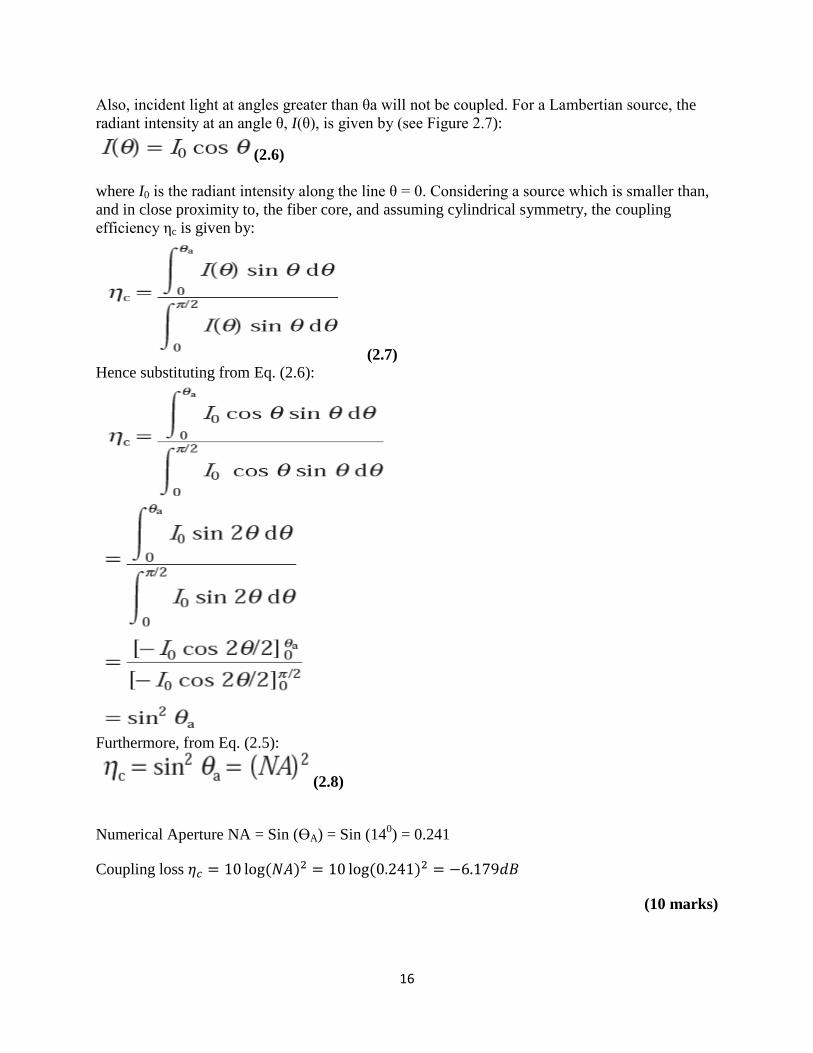
Also, incident light at angles greater than θa will not be coupled. For a Lambertian source, the
radiant intensity at an angle θ, I(θ), is given by (see Figure 2.7):
(2.6)
where I0 is the radiant intensity along the line θ = 0. Considering a source which is smaller than,
and in close proximity to, the fiber core, and assuming cylindrical symmetry, the coupling
efficiency ηc is given by:
(2.7)
Hence substituting from Eq. (2.6):
Furthermore, from Eq. (2.5):
(2.8)
Numerical Aperture NA = Sin (ϴA) = Sin (140) = 0.241
Coupling loss ( ) ( )
(10 marks)
17
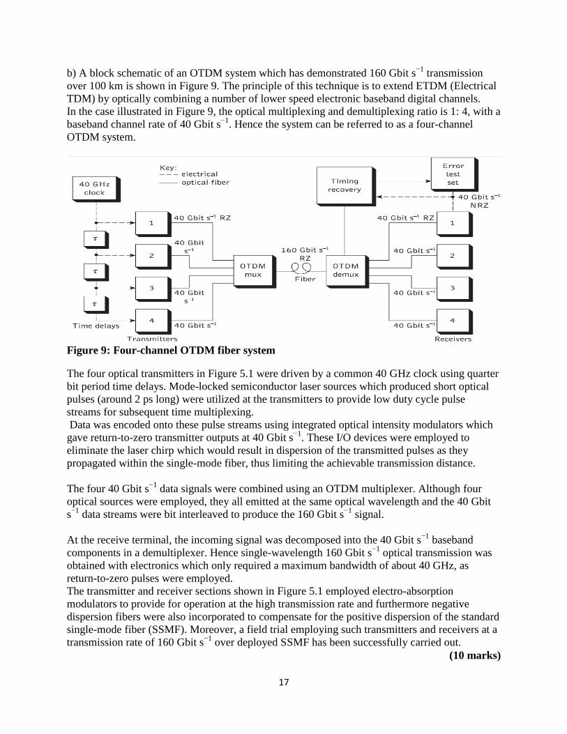
b) A block schematic of an OTDM system which has demonstrated 160 Gbit s−1
transmission
over 100 km is shown in Figure 9. The principle of this technique is to extend ETDM (Electrical
TDM) by optically combining a number of lower speed electronic baseband digital channels.
In the case illustrated in Figure 9, the optical multiplexing and demultiplexing ratio is 1: 4, with a
baseband channel rate of 40 Gbit s−1
. Hence the system can be referred to as a four-channel
OTDM system.
Figure 9: Four-channel OTDM fiber system
The four optical transmitters in Figure 5.1 were driven by a common 40 GHz clock using quarter
bit period time delays. Mode-locked semiconductor laser sources which produced short optical
pulses (around 2 ps long) were utilized at the transmitters to provide low duty cycle pulse
streams for subsequent time multiplexing.
Data was encoded onto these pulse streams using integrated optical intensity modulators which
gave return-to-zero transmitter outputs at 40 Gbit s−1
. These I/O devices were employed to
eliminate the laser chirp which would result in dispersion of the transmitted pulses as they
propagated within the single-mode fiber, thus limiting the achievable transmission distance.
The four 40 Gbit s−1
data signals were combined using an OTDM multiplexer. Although four
optical sources were employed, they all emitted at the same optical wavelength and the 40 Gbit
s−1
data streams were bit interleaved to produce the 160 Gbit s−1
signal.
At the receive terminal, the incoming signal was decomposed into the 40 Gbit s−1
baseband
components in a demultiplexer. Hence single-wavelength 160 Gbit s−1
optical transmission was
obtained with electronics which only required a maximum bandwidth of about 40 GHz, as
return-to-zero pulses were employed.
The transmitter and receiver sections shown in Figure 5.1 employed electro-absorption
modulators to provide for operation at the high transmission rate and furthermore negative
dispersion fibers were also incorporated to compensate for the positive dispersion of the standard
single-mode fiber (SSMF). Moreover, a field trial employing such transmitters and receivers at a
transmission rate of 160 Gbit s−1
over deployed SSMF has been successfully carried out.
(10 marks)