Embed Size (px)
Citation preview

MAIN DESIGN FEATURES AND ENGINEERING
CHALLENGES
Presented by G. Spigo on behalf of the joint Russian-Italian working group
1

2
TABLE OF CONTENTS
1. INTRODUCTION2. ELECTRICAL AND MECHANICAL COMPONENTS3. STRUCTURAL DESIGN CONCEPTS4. TECHNICAL AND DESIGN ISSUES TO BE SETTLED5. CLOSURE OF THE VACUUM VESSEL – WELDING AND INSPECTIONS6. ARC WELDING OF THE STUDS TO THE VACUUM VESSEL7. TOROIDAL COIL TURN - COOLING GROOVE MACHINING AND COVER
PLATE EWB WELDING8. MATING INTERFACES FRICTION COEFFICIENT MEASUREMENT9. CHARACTERIZATION OF THE SHEAR STRENGTH PROPERTIES OF
THE INSULATING MATERIAL FOR THE SOLENOIDAL COILS10. MECHANICAL AND ELECTRICAL TESTS ON SOLENOID CABLES11. POLOIDAL COIL WOUND WITH MgB2 SUPERCONDUCTING CABLE12. REFERENCES

INTRODUCTIONThe current project has been developed by ENEA under the leadership,guidance and supervision of Prof. B. Coppi of the MIT (MassachusettsInstitute of Technology) in collaboration with Ansaldo (Italy) as industrialpartner for the engineering the overall design.In close cooperation with Prof. B Coppi and ENEA, Ansaldo performed theconceptual and detailed study in order to verify the structural and industrialfeasibility of the object, forecast to ignite the toroidal plasma with a strongrate of ohmic heating.The most important items of the assembly, shown in the list below, wereexamined and studied exhaustively.
Subsequently, a complete design was carried out to understand the mostcritical points and the best possible ways to solve them conveniently. Inaddition, to obtain crucial information to validate the adopted decisionsseveral mockups such as coils, vacuum chamber and stainless steelstructures were manufactured and somehow tested in the meantime. 3
1) Central Solenoid2) Vacuum Chamber3) First Wall4) Radial Preloading System5) C-Clamps Structure6) Toroidal and Poloidal Coils

4
IGNITOR is a compact fusion machine studied for producing high plasmacurrent in order to attain both the temperature and the energy confinementnecessary for plasma ignition.Its layout consists of twelve modules of 30° each housing two toroidal fieldcoils. Poloidal coils are placed in the assembled aggregate and kept inposition with both radial and axial preloading structures.
POLOIDAL COILSSOLENOID
TOROIDAL COILS
RADIAL and AXIAL PRELOADING STRUCTURES

5
ELECTRICAL AND MECHANICAL COMPONENTS The main electrical components of IGNITOR are the following:
1. Toroidal magnet assembly composed of 24 CuOFHC coils2. Poloidal magnet arrangement constituted of 6x2 CuOFHC coils (up and
down with respect to the equatorial section) plus 2x2 coils supplying theactive preloading system (shrink fit).
3. Graded Ohmic Transformer (central solenoid) composed of 7x2 CuOFHCcoils (different percentage of cold work among conductor layers).
The principal mechanical features of IGNITOR are the following:1. Central post providing a compressing preload in vertical direction.2. C-Clamp structure composed of 48 modules, 7.5° each, grouped in
number of 4 to realize twelve 30° modules, each of them housing twotoroidal coils and being the support of the vacuum vessel.
3. 2 bracing rings, surrounding the C-Clamps assembly producing a passivepreload in radial direction and ancillary structures as support for theouter poloidal coils.
4. 2x2 circular coils, surrounding the C-Clamp, producing, when energized,an active compressive load in radial direction.
5. 2 reinforcing rings encircling the 2x2 coils generating the activecompressive force when energized.
6. The vacuum chamber holding the first wall and enveloping the plasma.
6
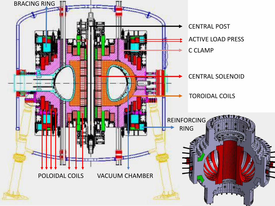
C CLAMP
CENTRAL POST
CENTRAL SOLENOID
TOROIDAL COILS
POLOIDAL COILS VACUUM CHAMBER
ACTIVE LOAD PRESS
BRACING RING
REINFORCING RING
7
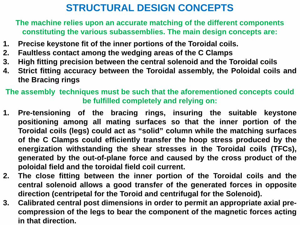
STRUCTURAL DESIGN CONCEPTSThe machine relies upon an accurate matching of the different components
constituting the various subassemblies. The main design concepts are:1. Precise keystone fit of the inner portions of the Toroidal coils.2. Faultless contact among the wedging areas of the C Clamps3. High fitting precision between the central solenoid and the Toroidal coils4. Strict fitting accuracy between the Toroidal assembly, the Poloidal coils and
the Bracing ringsThe assembly techniques must be such that the aforementioned concepts could
be fulfilled completely and relying on:1. Pre-tensioning of the bracing rings, insuring the suitable keystone
positioning among all mating surfaces so that the inner portion of theToroidal coils (legs) could act as “solid” column while the matching surfacesof the C Clamps could efficiently transfer the hoop stress produced by theenergization withstanding the shear stresses in the Toroidal coils (TFCs),generated by the out-of-plane force and caused by the cross product of thepoloidal field and the toroidal field coil current.
2. The close fitting between the inner portion of the Toroidal coils and thecentral solenoid allows a good transfer of the generated forces in oppositedirection (centripetal for the Toroid and centrifugal for the Solenoid).
3. Calibrated central post dimensions in order to permit an appropriate axial pre-compression of the legs to bear the component of the magnetic forces actingin that direction.

8
Keystone Fit
The size and the shape of the wedging and bucking surfaces are paramount topermit the most appropriate development of the force transfer chains for bothradial and axial loads. Extensive runs of calculations show that the areas,indicated in the above pictures, are the most effective ones to fulfill the needs ofmechanical robustness and electrical performance of the apparatus. To preciselyfit all these components, it is also foreseen a proper machining of the radial gapsbetween the Solenoid and the TFCs during the initial machine assembly.
bucking surface

9
As already mentioned, the other essentialcomponent of IGNITOR is the toroidalshaped Vacuum Vessel (VV), which hasvariable thicknesses (26-36-52 mm) towithstand the Vertical Displacement Event(VDE) loads while having a more uniformstress distribution. It is worth noting thatthe VV is fully welded to achieve therequired high strength and electricresistivity. The welding thickness amongmodules is always the same (26 mm)implying that the connecting surfaces aremachined accordingly.The VV also serves as support for the firstwall protection composed of molybdenumalloy (TZM) tiles precisely positionedrelatively to the magnetic field lines tominimized thermal loads concentrations.The size of the tile is defined consideringthe EM loads generated throughoutplasma disruption.The tiles are screwed to supporting plates(carriers), fixed to the VV by means ofstuds accurately arc welded to the VV wall.

10
TECHNICAL AND DESIGN ISSUES TO BE SETTLEDThe previous transparencies showed a well focused and complete design effortwhere the main choices, solutions and proposals were validated by models andprototypes documenting that a manufacturing process for the soundly blueprintobjects can be launched.In fact, in the years 2000 an intense R&D program was established to check theindustrial feasibility of the design and, then, tune it up to be ready for thesubsequent production step.
TRANSFORMER
VACUUM CHAMBER TOROIDAL COIL

11
C CLAMP
MULTIPLE BARREL HIGH SPEED PELLET INJECTOR ICRH VACUUM TRANSMISSION AND ANTENNA
TOROIDAL COILEB WELDING

12
The joint Russian-Italian working group, in charge of the publishing of theConceptual Design Review (CDR), in its analysis has highlighted specifictechnological points and topics needing further investigations anddevelopments. Among all the analyzed subjects, the working group hasidentified and selected a list of matters to be resolved that are consideredhighly significant in order to be confident about the successful completionof the project.The identified issues, called mock-ups in the CDR, are the following:1. Welding for the closure of the Vacuum Vessel (tooling, procedures and
tests).2. Machining of the cooling groove in the Toroidal coil turn and Electron
Beam Welding (EWB) of the cover plate and related inspections.3. Welding of Nelson studs to the Vacuum Vessel. Definition of the welding
parameters and procedures to obtain a parallel and straight position ofthe studs among themselves.
4. Measurement of the friction coefficient between mating interfaces.5. Measurement of shear strength for the insulating material of solenoid
coils.6. Mechanical and electrical tests on central solenoid conductors.7. Remote handling and manipulation of the TZM tiles.8. Model of poloidal coil number 14 wound with an MgB2 superconductor.

13
CLOSURE OF THE VACUUM VESSEL – WELDING AND INSPECTIONSDue to the lack of space and access, the final assembly and the welding closureof the vacuum chamber needs to be executed remotely operating from thechamber equatorial port. This means that a specific tool is needed. This consistsin an articulated boom inserted through the equatorial ports and equipped witheither a welding torch (laser for root pass and TIG for filling the rest) or a weldinginspection apparatus. Moreover, this tool will have to be able to carry out otherdevices in case of repair (grinding and cleaning tools). Thus, a dedicated mock-up, simulating a portion of the toroidal chamber with its access port, is necessaryto perform tests with an expressly dedicated welding robot because industrialones cannot fulfill the needs. This robot is an essential part of the R&D program,which might be adapted or used as it is for the subsequent final assembly on site.

14
ARC WELDING OF THE STUDS TO THE VACUUM VESSELThe first wall made of TZM tiles is a VV protective shielding for both particles andradiative heating that are produced by the plasma. These tiles cover the completesurface of the VV. The tile is brazed to a square back plate. The back plate isinterlocked in the specifically shaped carrier groove and screwed to the carrier.The shape of the groove is such that any rotation of the tile is prevented. A givennumber of tiles are fixed to the carrier, which is bolted to the VV with special boltsengaging the protruding threaded Nelson studs arc welded to the VV. Therefore,the stud placement is paramount for both carrier fixation and upkeep.

15

16
TOROIDAL COIL TURN COOLING GROOVE MACHINING AND COVER PLATE EWB WELDING
For a more efficient cooling of the toroidal coils and a subsequent shorter coolingtime between two experimental attempts, the turns are cooled on their internalperiphery by means of channels where the helium can flow. The channels areobtained by making a rectangular groove that will be covered with a strip that isgoing to be welded using the electron-beam technique. The mock-up must verifythe feasibility of the machining, the accurate positioning of the closing strip andthe following EWB welding requiring a vacuum chamber of adequate size. It oughtto be furthermore tested the deep drilling connecting the inside channels to theinlet/outlet feeding cooling system.

17
MATING INTERFACES FRICTION COEFFICIENT MEASUREMENTMaterials having a low friction coefficient value, inserted between two matingsurfaces are essential for the correct performance of IGNITOR. The interfacebetween the C-Clamp and the Toroidal coil is one of the zones where this need ismore evident. In addition to friction values ranging between 0.05 and 0.1 invacuum and at cryogenic temperature, these materials must withstand pressuresclose to 150 MPa and, therefore, be extremely robust in terms of stress, cyclingfatigue, abrasion and radiation resistance. For the interface between the solenoidand the TFCs, the pressure is even larger (around 300 MPa). Promising materials,already known and under study, must be checked and validated for our purposes.

18
CHARACTERIZATION OF THE SHEAR STRENGTH PROPERTIES OF THE INSULATING MATERIAL FOR THE SOLENOIDAL COILS
It is of a great importance the evaluation of the shear strength 𝝉𝝉 as function of thecompressive stress 𝝈𝝈𝒏𝒏 perpendicular to the insulation layer at both room andcryogenic temperature. The knowledge of these characteristics are fundamentalfor the manufacturing soundness of the most critical components of the machine.Previous performed tests results on TFCs turn insulation, at room and LN2temperatures, can be expressed and formulated with the two Coulombian lawsshown below, where τ0 is the shear stress at no compression.
𝝉𝝉 = 𝝉𝝉𝟎𝟎 + 𝒇𝒇𝒔𝒔𝝈𝝈𝒏𝒏 = 𝟓𝟓𝟓𝟓.𝟒𝟒 + 𝟎𝟎.𝟐𝟐𝟐𝟐𝟐𝟐 𝝈𝝈𝒏𝒏 𝒂𝒂𝒂𝒂 𝟐𝟐𝟐𝟐𝟐𝟐 𝑲𝑲𝝉𝝉 = 𝝉𝝉𝟎𝟎 + 𝒇𝒇𝒔𝒔𝝈𝝈𝒏𝒏 = 𝟐𝟐𝟖𝟖.𝟏𝟏 + 𝟎𝟎.𝟐𝟐𝟐𝟐𝟓𝟓 𝝈𝝈𝒏𝒏 𝒂𝒂𝒂𝒂 𝟖𝟖𝟖𝟖 𝑲𝑲
As no test was carried out for the insulation of the solenoid, the calculations weremade considering a constant 𝒇𝒇𝒔𝒔 value of 0.35 at any temperatures and 𝝉𝝉𝟎𝟎 figuresreflecting the insulation shear stresses under different scenarios. Therefore, theconfirmation of the adequacy of 𝝉𝝉𝟎𝟎 and 𝒇𝒇𝒔𝒔 input in the FEA computation isessential to be confident for the subsequent production of the solenoidal coils.
19
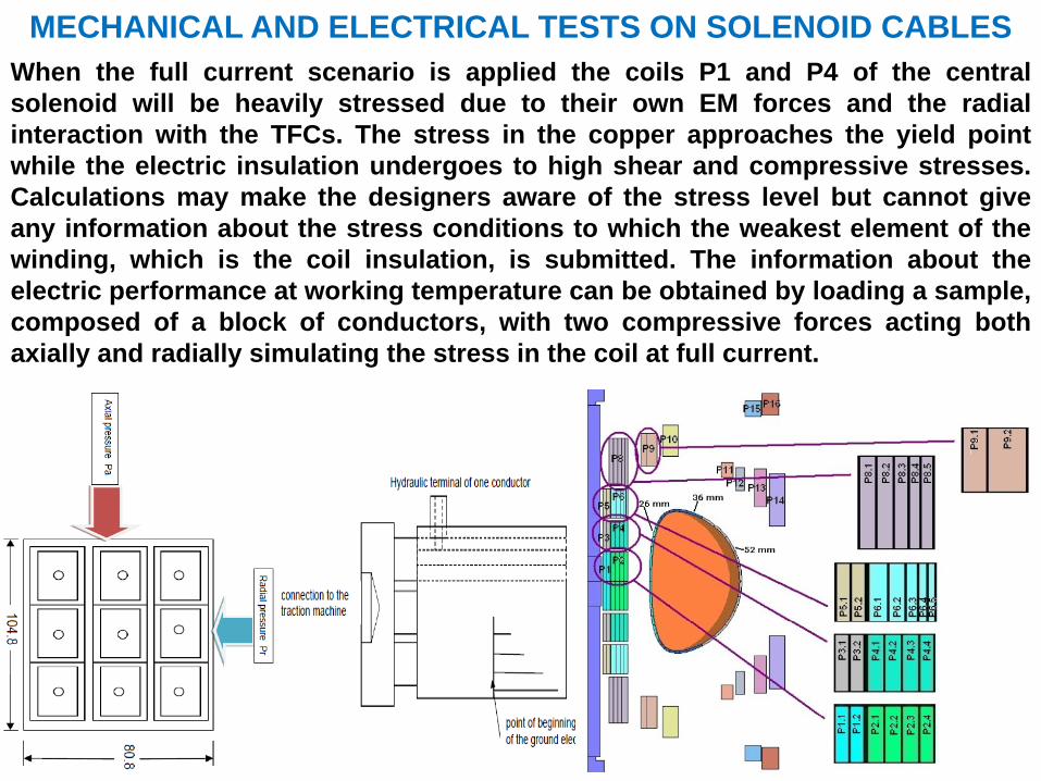
MECHANICAL AND ELECTRICAL TESTS ON SOLENOID CABLESWhen the full current scenario is applied the coils P1 and P4 of the centralsolenoid will be heavily stressed due to their own EM forces and the radialinteraction with the TFCs. The stress in the copper approaches the yield pointwhile the electric insulation undergoes to high shear and compressive stresses.Calculations may make the designers aware of the stress level but cannot giveany information about the stress conditions to which the weakest element of thewinding, which is the coil insulation, is submitted. The information about theelectric performance at working temperature can be obtained by loading a sample,composed of a block of conductors, with two compressive forces acting bothaxially and radially simulating the stress in the coil at full current.

20
POLOIDAL COIL WOUND WITH MgB2 SUPERCONDUCTING CABLEDue its size (Ø 5 m) and its operating current and field (34.7 kA and 5 T), the P14 isthe best candidate to be wound with MgB2 as the magnetic field for the other coilsis higher. Since the original copper coil may present manufacturing issues due toits large size, a previous design revision proposed the possibility to make a coilwith an HTc like the MgB2 that in future projects, in combination of Cu coils, mayimprove the plasma duty cycle. Its application would permit a reduction of thedissipated power and an increase in mechanical strength. To attain theaforementioned performances, the MgB2 coil is cooled at 8-10 K, which iscompatible with He gas flow at 30 K of the cooling system of the machine byadding a heat exchanger and a Joule-Thomson valve to the actual cryogeniclayout. The forecast model (Øinner 1 m, Øouter 1.9 m) will operate at the same currentand magnetic field density leading to proportional loads and stresses in the coil.
COPPER TUBESTAINLESS STEEL TUBE
He GAS FLOW
RESIN

21
REFERENCES AND PICTURES
1. THE IGNITOR PROJECT CONCEPTUAL DESIGN REPORT2. T. Grandt, G. Theiler – Tribological Behaviour of Composite in Vacuum3. Z. Piec, J. Nowacki – Friction Material Operating Under High Stress..4. G. Grasso, R. Penco – Technical Specification – Columbus
Superconductors