Embed Size (px)
Citation preview

Temperature
Magnetic surface thermocoupleFor high temperaturesModel TC52-M
Magnetic surface thermocouple, model TC52-M
Applications
■ Tanks ■ Reactor shells ■ High-pressure and high-temperature reactors ■ Coke drums and shells ■ Hydrocracker units
Special features
■ Simplified maintenance and sensor removal without the use of specialised tools
■ Maximum surface contact tip design ■ High-temperature applications (up to 540 °C [1,000 °F])
Description
The magnetic thermocouple is designed as a non-welded option for vessel wall temperature measurement. The circular magnet design incorporates an insulation barrier from radiant heat along with a sensor tip designed to maximise surface contact to ensure accurate temperature measurement.
The neck extension can be manufactured to length based on insulation thickness. The spring-loaded neck extension ensures sensor contact with the vessel wall and allows for maintenance without the use of tools above the insulation/cladding of the vessel.
WIKA data sheet TE 66.52
Page 1 of 22WIKA data sheet TE 66.52 ∙ 11/2021

Page 2 of 22WIKA data sheet TE 66.52 ∙ 11/2021
Sensor
Thermocouple per IEC 60584-1 or ASTM E230Types K, J, E, N, T (single or dual thermocouple)
Measuring locationWelded to the bottom (grounded)
Sensor types
Type Validity limits of the class accuracyIEC 60584-1 ASTM E230Class 2 Class 1 Standard / special
K -40 ... +1,200 °C [-40 ... +2,192 °F] -40 ... +1,000 °C [-40 ... +1,832 °F] 0 ... 1,260 °C [0 ... 2,300 °F]J -40 ... +750 °C [-40 ... +1,382 °F] -40 ... +750 °C [-40 ... +1,382 °F] 0 ... 760 °C [0 ... 1,400 °F]E -40 ... +900 °C [-40 ... +1,652 °F] -40 ... +800 °C [-40 ... +1,472 °F] 0 ... 870 °C [0 ... 1,598 °F]N -40 ... +1,200 °C [-40 ... +2,192 °F] -40 ... +1,000 °C [-40 ... +1,832 °F] 0 ... 1,260 °C [0 ... 2,300 °F]T -40 ... +350 °C [-40 ... +662 °F] -40 ... +350 °C [-40 ... +662 °F] 0 ... 370 °C [0 ... 698 °F]
The table shows the temperature ranges listed in the respective standards, in which the tolerance values (class accuracies) are valid.
The actual operating temperature of the thermometer is limited both by the maximum permissible working temperature, the diameter of the thermocouple and the sheathed cable, as well as by the maximum permissible working temperature of the sheath material.
For detailed specifications for thermocouples, see IEC 60584-1 or ASTM E230 and Technical information IN 00.23 at www.wika.com.
Cold junction temperatureFor the tolerance value of thermocouples, a cold junction temperature of 0 °C [32 °F] has been taken as the basis.
Thermocouple Measuring point
Sheath

Page 3 of 22WIKA data sheet TE 66.52 ∙ 11/2021
Minimum and maximum operating temperature
Process temperature
Ambient temperature
Process temperatureThe process temperature is the temperature which prevails in the area between the probe tip and the process connection. This generally corresponds to the temperatures for which the thermocouple has been defined in accordance with IEC 60584-1 or ASTM E230 standard.
■ Sheath material Ni alloy: Alloy 600- up to 1,200 °C [2,192 °F] (air)- standard material for applications which require specific
corrosion-resistant properties under exposure to high temperatures, resistant to induced stress corrosion cracking and pitting corrosion in media containing chloride
- resistant to corrosion caused by aqueous ammonia in all temperatures and concentrations
- highly resistant to halogens, chlorine, hydrogen chloride ■ Sheath material stainless steel
- up to 850 °C [1,562 °F] (air)- good resistance against aggressive media and also
against vapour and combustion gases in chemical media
Ambient temperatureThe area of the transition from MI cable to connection cable (see page 8) and all subsequent components are located in the region of ambient temperature.
If the ambient temperature is higher than the permissible temperature at the cable, connector or transition, the metal parts of the probe must be long enough so that the transition is located outside of the hot zone. At any point on the connection cable, the maximum temperature that may be attained is that for which the connection cable is specified. The probe itself can – within the validity limits of its class accuracy – be loaded higher.
It is important to ensure that the lowest of the maximum permissible ambient temperatures for connection cables, materials used such as sealing compounds in the transition sleeve or a fitted connector or case is not exceeded.
■ Maximum temperature at connection housing: 85 °C [185 °F] ■ Maximum temperature at connector: 85 °C [185 °F] ■ Maximum temperature of the sealing compound at the
transition: 250 °C [482 °F] ■ Maximum temperature of vibration-resistant versions: 200 °C
[392 °F] ■ In an optional approval minimum and maximum
temperature specifiedOther variants on request
For information on the maximum permissible operating temperatures for the connection cable see page 9.

Page 4 of 22WIKA data sheet TE 66.52 ∙ 11/2021
General design of the TC52-M
In sheathed thermocouples the flexible part of the probe consists of a mineral-insulated cable (MI cable). It features a metal outer sheath, which contains the insulated internal leads, embedded within a high-density ceramic compound.
Due to their flexibility and the small possible diameters, sheathed thermocouples can also be used in locations that are not easily accessible, since, with the exception of the probe tip and the transition sleeve of the connection cable, the sheath can be bent to a radius of five times the diameter of the cable.
Mineral-insulated cable (MI cable)
WL AT
14371722.01Ød
WL A
ØdT
14371744.01
W AT
3160700.03
Ød
L AT
3162362.03
Ød
WL A
ØdT
3162371.03
A
ØdØd
W AT
Page 5 of 22WIKA data sheet TE 66.52 ∙ 11/2021
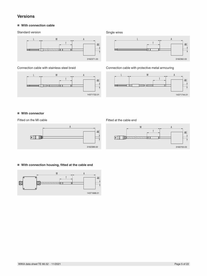
■ With connection cable
Standard version Single wires
Connection cable with stainless steel braid Connection cable with protective metal armouring
Versions
3162371.03 3162362.03
14371722.01 14371744.01
3162389.02
14371688.01
3160700.03
■ With connector
■ With connection housing, fitted at the cable end
Fitted on the MI cable Fitted at the cable end
Page 6 of 22WIKA data sheet TE 66.52 ∙ 11/2021
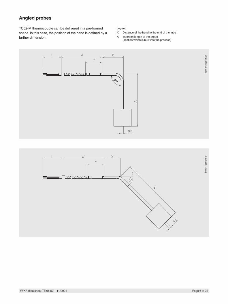
Angled probes
TC52-M thermocouple can be delivered in a pre-formed shape. In this case, the position of the bend is defined by a further dimension.
from
113
5654
6.01
from
113
5655
4.01
Legend:X Distance of the bend to the end of the tubeA Insertion length of the probe
(section which is built into the process)

Page 7 of 22WIKA data sheet TE 66.52 ∙ 11/2021
Process connection
Spring-loaded magnetic bushing
SpecificationsApplications ■ Refinery and chemical industries
■ Oil and gas industries ■ Offshore exploration and drilling ■ Pulp and paper ■ Gas plants
Special features ■ High-temperature magnetic material for removable installation of a thermocouple or RTD sensor
■ Various neck lengths available on requestMaterials
Spring-loaded neck assembly 316SSInsulation material High temperatures > 600 °C [1,100 °F]
MgO base fibre-reinforcedThermal conductivity = 4 BTU-in/°FHr.Ft2
Spring material High-temperature alloy 600Magnet material Alnico 5
Magnet propertiesHolding force (under ambient conditions) 150 lbs [650 N] approximatelyDensity 0.265 lb/in3
Curie temperature 840 °C [1,544 °F]Maximum practical operating temperature 540 °C [1,000 °F]Rockwell hardness Rc50
Packaging and storageDo not remove packaging until just before mounting. Keep the packaging (keeper) as it will provide optimum protection during transport (e.g. change in installation site). Loss of magnetism can occur if the keeper is not provided. Avoid mechanical shock (putting down hard).
ø 90 [ø 3 1/2]
64[2 1/2]
108[4 1/4]
Abmessungen in mm [in]

Page 8 of 22WIKA data sheet TE 66.52 ∙ 11/2021
Transition
Standard versionThe junction between the metal part of the probe and the connection lead or stranded wire must not be bent. Compression fittings should not be attached to the transition sleeve.
The dimensions of the transition sleeve are dependent upon the probe diameter, on the construction of the connection cable and its number of inner conductors - depending on the connection method. Also, operation with ambient temperatures < -40 °C [-40 °F] has an influence on the dimensions of the transition sleeve.
Bend protection
A bend protection (spring or shrink hose) is used to protect the transition point from rigid probe to flexible connection lead. This should always be used when a relative movement between the connection lead and the thermometer mounting is expected.
Bend protection spring
Shrink hose
Both versions should be considered to be technically equivalent with respect to their function as bend protection.

Page 9 of 22WIKA data sheet TE 66.52 ∙ 11/2021
Connection cable, jacket
Cable jacket Application range 1)
PTFE/PFA -60 ... +250 °C [-76 ... +482 °F]PTFE/PFA, shielded (see standard versions below) -60 ... +250 °C [-76 ... +482 °F]Single wires, PTFE/PFA -60 ... +250 °C [-76 ... +482 °F]Stainless steel braid over PTFE/PFA -60 ... +250 °C [-76 ... +482 °F]Silicone -50 ... +180 °C [-58 ... +356 °F]Silicone, shielded (see standard versions below) -50 ... +180 °C [-58 ... +356 °F]PVC -20 ... +100 °C [-4 ... +212 °F]Fibreglass -50 ... +400 °C [-58 ... +752 °F]Stainless steel braid over fibreglass -50 ... +400 °C [-58 ... +752 °F]Protective metal armouring over PTFE/PFA -60 ... +250 °C [-76 ... +482 °F]Protective metal armouring with PTFE/PFA sheath over PTFE/PFA -60 ... +250 °C [-76 ... +482 °F]Protective metal armouring with PVC sheath over PVC -20 ... +100 °C [-4 ... +212 °F]Protective metal armouring with PE sheath over PTFE/PFA -50 ... +250 °C [-58 ... +482 °F]
1) Minimum/Maximum temperatures valid for stationary cable. The actual operating temperature (process temperature) of the thermometer can deviate.
Colour code of cable
Sensor type
Standard Thermocouple cable, compensating cableOuter sheath Positive Negative
K IEC 60584-3 Green Green WhiteJ IEC 60584-3 Black Black WhiteE IEC 60584-3 Violet Violet WhiteT IEC 60584-3 Brown Brown WhiteN IEC 60584-3 Pink Pink White
Sensor type
Standard Thermocouple cable Compensating cableOuter sheath Positive Negative Outer sheath Positive Negative
K ASTM E230 Brown Yellow Red Yellow Yellow RedJ ASTM E230 Brown White Red Black White RedE ASTM E230 Brown Violet Red Violet Violet RedT ASTM E230 Brown Blue Red Blue Blue RedN ASTM E230 Brown Orange Red Orange Orange Red
For further information on colour coding, see Technical information IN 00.23 at www.wika.com.
Standard cable lengthsMetric lengths Imperial lengths
■ 1,000 mm ■ 24 in ■ 2,000 mm ■ 36 in ■ 3,000 mm ■ 72 in ■ 5,000 mm ■ 144 in
Other cable lengths are possible

Page 10 of 22WIKA data sheet TE 66.52 ∙ 11/2021
Design of the lead ends
Version IllustrationFlying leads
End splices
Spade lugs (fork design)
Cord grip
Thread size Material IllustrationWithout -
M16 x 1.5 PlasticM20 x 1.5 Plastic1/2 NPT Plastic1/2 NPT Metal3/4 NPT Metal
Standard versions of the shield electrical connection ■ Shield not connected at the sensor, stripped lead at the end of the cable ■ Shield connected at the sensor, stripped lead at the end of the cable
■ Shield not connected at the sensor, connected at the housing ■ Shield connected at the sensor, connected at the case
■ Shield not connected at the sensor, connected at the connector ■ Shield connected at the sensor, connected at the connector ■ Shield connected at the sensor, not connected at the connector
Other versions on request

Page 11 of 22WIKA data sheet TE 66.52 ∙ 11/2021
Connection housing (option)
Illustration Model Material Cable entry thread size
Cover Surface Other
Field case Plastic (ABS) ■ M12 x 1.5 ■ 1/2 NPT ■ M16 x 1.5
Flat cover with 4 plug screws
Grey ■ 82 x 80 x 55 mm [3.2 x 3.1 x 2.2 in] (L x W x H)
■ Inputs on one sideField case Aluminium ■ M12 x 1.5
■ 1/2 NPT ■ M16 x 1.5
Flat cover with 4 plug screws
Natural finish
■ 80 x 75 x 57 mm [3.1 x 2.9 x 2.3 in] (L x W x H)
■ Inputs on one sideField case Plastic (ABS) ■ M12 x 1.5
■ 1/2 NPT ■ M16 x 1.5
Flat cover with 4 plug screws
Grey ■ 82 x 80 x 55 mm [3.2 x 3.1 x 2.2 in] (L x W x H)
■ Inputs opposite each other
Field case Aluminium ■ M12 x 1.5 ■ 1/2 NPT ■ M16 x 1.5
Flat cover with 4 plug screws
Natural finish
■ 80 x 75 x 57 mm [3.1 x 2.9 x 2.3 in] (L x W x H)
■ Inputs opposite each other
1/4000 Aluminium ■ M20 x 1.5 ■ 1/2 NPT ■ 3/4 NPT
Screw-on lid Blue, painted 1)
-
1/4000 Stainless steel ■ M20 x 1.5 ■ 1/2 NPT ■ 3/4 NPT
Screw-on lid Natural finish
-
7/8000 Aluminium ■ M20 x 1.5 ■ 1/2 NPT ■ 3/4 NPT
Screw-on lid Blue, painted 1)
-
7/8000 Stainless steel ■ M20 x 1.5 ■ 1/2 NPT ■ 3/4 NPT
Screw-on lid Natural finish
-
7/8000 Aluminium ■ M20 x 1.5 ■ 1/2 NPT ■ 3/4 NPT
Screw-on lid, with digital temperature display, model DIH50-B
Blue, painted 1)
-
7/8000 Stainless steel ■ M20 x 1.5 ■ 1/2 NPT ■ 3/4 NPT
Screw-on lid, with digital temperature display, model DIH50-B
Natural finish
-
5/6000 Aluminium ■ 2 x M20 x 1.5 ■ 2 x 1/2 NPT ■ 2 x 3/4 NPT
Screw-on lid Blue, painted 1)
-
5/6000 Stainless steel ■ 2 x M20 x 1.5 ■ 2 x 1/2 NPT ■ 2 x 3/4 NPT
Screw-on lid Natural finish
-
5/6000 Aluminium ■ 2 x M20 x 1.5 ■ 2 x 1/2 NPT ■ 2 x 3/4 NPT
Screw-on lid, with digital temperature display, model DIH50-B
Blue, painted 1)
-
5/6000 Stainless steel ■ 2 x M20 x 1.5 ■ 2 x 1/2 NPT ■ 2 x 3/4 NPT
Screw-on lid, with digital temperature display, model DIH50-B
Natural finish
-
7/8000 DIH50 KN4-PBVS BVS (NuG)JS 7/80005/60001/4000 andere AnschlussgehäuseBS BSZ, BSZ-K BSZ-H, BSZ-HK BSS BSS-H BVC
7/8000 DIH50 KN4-PBVS BVS (NuG)JS 7/80005/60001/4000 andere AnschlussgehäuseBS BSZ, BSZ-K BSZ-H, BSZ-HK BSS BSS-H BVC
7/8000 DIH50 KN4-PBVS BVS (NuG)JS 7/80005/60001/4000 andere AnschlussgehäuseBS BSZ, BSZ-K BSZ-H, BSZ-HK BSS BSS-H BVC
7/8000 DIH50 KN4-PBVS BVS (NuG)JS 7/80005/60001/4000 andere AnschlussgehäuseBS BSZ, BSZ-K BSZ-H, BSZ-HK BSS BSS-H BVC

Page 12 of 22WIKA data sheet TE 66.52 ∙ 11/2021
Illustration Model Material Cable entry thread size
Cover Surface Other
Field transmitter TIF50
Aluminium ■ 2 x M20 x 1.5 ■ 2 x 1/2 NPT ■ 2 x 3/4 NPT
Screw-on lid, with digital temperature display, model DIH50-B
Blue, painted 1)
-
Field transmitter TIF50
Stainless steel ■ 2 x M20 x 1.5 ■ 2 x 1/2 NPT ■ 2 x 3/4 NPT
- Natural finish
-
Field transmitter TIF52
Aluminium ■ 2 x M20 x 1.5 ■ 2 x 1/2 NPT ■ 2 x 3/4 NPT
- - -
Field transmitter TIF52
Stainless steel ■ 2 x M20 x 1.5 ■ 2 x 1/2 NPT ■ 2 x 3/4 NPT
- - -
KN4-A Aluminium ■ M20 x 1.5 ■ 1/2 NPT ■ 3/4 NPT
Screw-on lid Blue, painted 1)
-
KN4-P Polypropylene ■ M20 x 1.5 ■ 1/2 NPT ■ 3/4 NPT
Screw-on lid White -
BSZ Aluminium ■ M20 x 1.5 ■ 1/2 NPT
Spherical, hinged cover with plug screw
Blue, painted 1)
-
BSZ-H Aluminium ■ M20 x 1.5 ■ 1/2 NPT
High hinged cover with plug screw
Blue, painted 1)
-
1) RAL 5022
7/8000 DIH50 KN4-PBVS BVS (NuG)JS 7/80005/60001/4000 andere AnschlussgehäuseBS BSZ, BSZ-K BSZ-H, BSZ-HK BSS BSS-H BVC
7/8000 DIH50 KN4-PBVS BVS (NuG)JS 7/80005/60001/4000 andere AnschlussgehäuseBS BSZ, BSZ-K BSZ-H, BSZ-HK BSS BSS-H BVC
7/8000 DIH50 KN4-PBVS BVS (NuG)JS 7/80005/60001/4000 andere AnschlussgehäuseBS BSZ, BSZ-K BSZ-H, BSZ-HK BSS BSS-H BVC

Page 13 of 22WIKA data sheet TE 66.52 ∙ 11/2021
Position of the probe inputThe standard probe input is located at position C.Another position for the probe input is possible as an option.
Illustration Connection housingField case with inputs on either side
Field case with inputs on opposite sides
7/8000 DIH50 KN4-PBVS BVS (NuG)JS 7/80005/60001/4000 andere AnschlussgehäuseBS BSZ, BSZ-K BSZ-H, BSZ-HK BSS BSS-H BVC
A
C
Connection housing 1/4000
Connection housing 7/8000
Connection housing 7/8000 with DIH50
Connection housing 5/6000
A
C
B
Connection housing 5/6000 with DIH50-B
Field transmitter TIF50/TIF52
Connection head KN4-A
Connection head BSZ
Connection head BSZ-H
A C
A
C
A
C
7/8000 DIH50 KN4-PBVS BVS (NuG)JS 7/80005/60001/4000 andere AnschlussgehäuseBS BSZ, BSZ-K BSZ-H, BSZ-HK BSS BSS-H BVC
AB
C
7/8000 DIH50 KN4-PBVS BVS (NuG)JS 7/80005/60001/4000 andere AnschlussgehäuseBS BSZ, BSZ-K BSZ-H, BSZ-HK BSS BSS-H BVC
A
C
7/8000 DIH50 KN4-PBVS BVS (NuG)JS 7/80005/60001/4000 andere AnschlussgehäuseBS BSZ, BSZ-K BSZ-H, BSZ-HK BSS BSS-H BVC
A
C
7/8000 DIH50 KN4-PBVS BVS (NuG)JS 7/80005/60001/4000 andere AnschlussgehäuseBS BSZ, BSZ-K BSZ-H, BSZ-HK BSS BSS-H BVC
A
C
7/8000 DIH50 KN4-PBVS BVS (NuG)JS 7/80005/60001/4000 andere AnschlussgehäuseBS BSZ, BSZ-K BSZ-H, BSZ-HK BSS BSS-H BVC
Page 14 of 22WIKA data sheet TE 66.52 ∙ 11/2021
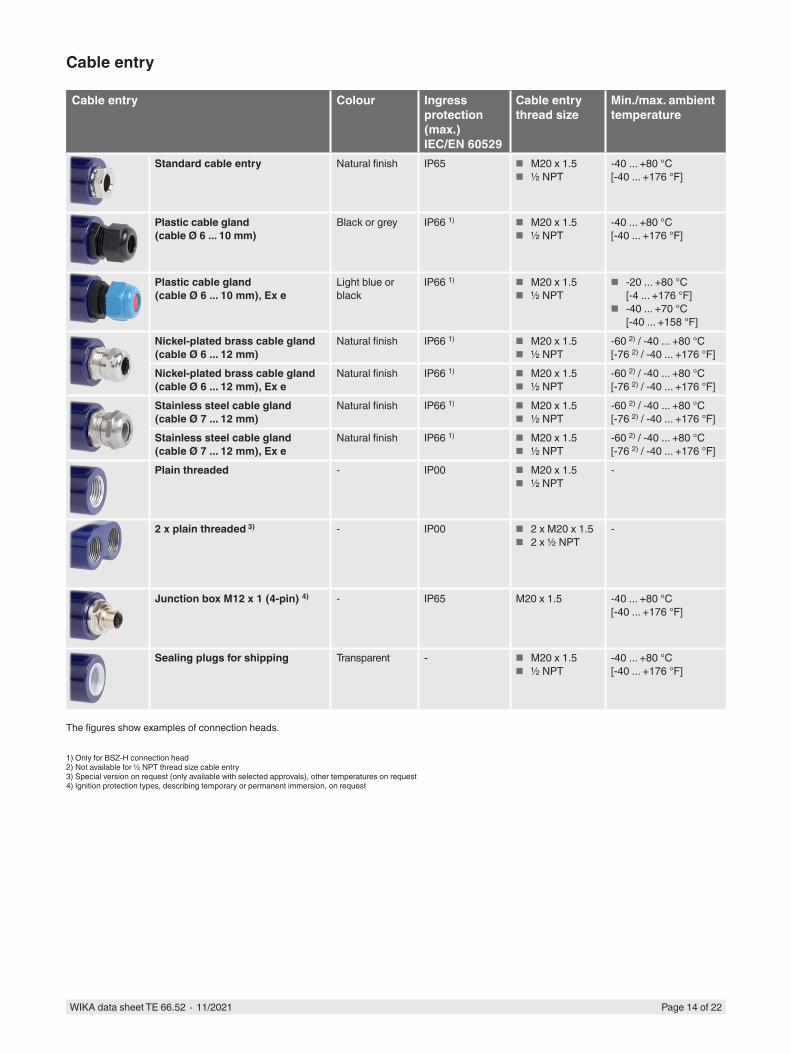
Cable entry
Cable entry Colour Ingress protection (max.) IEC/EN 60529
Cable entry thread size
Min./max. ambient temperature
Standard cable entry Natural finish IP65 ■ M20 x 1.5 ■ ½ NPT
-40 ... +80 °C [-40 ... +176 °F]
Plastic cable gland(cable Ø 6 ... 10 mm)
Black or grey IP66 1) ■ M20 x 1.5 ■ ½ NPT
-40 ... +80 °C [-40 ... +176 °F]
Plastic cable gland(cable Ø 6 ... 10 mm), Ex e
Light blue or black
IP66 1) ■ M20 x 1.5 ■ ½ NPT
■ -20 ... +80 °C [-4 ... +176 °F]
■ -40 ... +70 °C [-40 ... +158 °F]
Nickel-plated brass cable gland (cable Ø 6 ... 12 mm)
Natural finish IP66 1) ■ M20 x 1.5 ■ ½ NPT
-60 2) / -40 ... +80 °C [-76 2) / -40 ... +176 °F]
Nickel-plated brass cable gland (cable Ø 6 ... 12 mm), Ex e
Natural finish IP66 1) ■ M20 x 1.5 ■ ½ NPT
-60 2) / -40 ... +80 °C [-76 2) / -40 ... +176 °F]
Stainless steel cable gland(cable Ø 7 ... 12 mm)
Natural finish IP66 1) ■ M20 x 1.5 ■ ½ NPT
-60 2) / -40 ... +80 °C [-76 2) / -40 ... +176 °F]
Stainless steel cable gland(cable Ø 7 ... 12 mm), Ex e
Natural finish IP66 1) ■ M20 x 1.5 ■ ½ NPT
-60 2) / -40 ... +80 °C [-76 2) / -40 ... +176 °F]
Plain threaded - IP00 ■ M20 x 1.5 ■ ½ NPT
-
2 x plain threaded 3) - IP00 ■ 2 x M20 x 1.5 ■ 2 x ½ NPT
-
Junction box M12 x 1 (4-pin) 4) - IP65 M20 x 1.5 -40 ... +80 °C [-40 ... +176 °F]
Sealing plugs for shipping Transparent - ■ M20 x 1.5 ■ ½ NPT
-40 ... +80 °C [-40 ... +176 °F]
The figures show examples of connection heads.
1) Only for BSZ-H connection head2) Not available for ½ NPT thread size cable entry3) Special version on request (only available with selected approvals), other temperatures on request4) Ignition protection types, describing temporary or permanent immersion, on request

Page 15 of 22WIKA data sheet TE 66.52 ∙ 11/2021
Transmitter built into the connection housing (option)
A transmitter can be mounted in an optional connection housing.
Output signal 4 ... 20 mA and HART® protocolTransmitter (selectable versions) Model T16 Model T32Data sheet TE 16.01 TE 32.04Output
4 ... 20 mA x xHART® protocol - x
Explosion protection Optional Optional
Accessories, connection housing
Pipe-mounting kit, stainless steel (for field case) Pipe-mounting kit, stainless steel (for 5/6000, DIH50/DIH52, TIF50/TIF52)
Fixing bracket (for wall mounting) 92 x 60 x 50 mm [3.6 x 2.4 x 2.0 in], stainless steel (for connection head models BSZ and BSZ-H)
For detailed specifications on the explosion protection of the transmitter, see respective transmitter data sheet.
Page 16 of 22WIKA data sheet TE 66.52 ∙ 11/2021
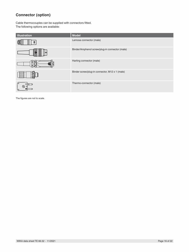
Connector (option)
Cable thermocouples can be supplied with connectors fitted.The following options are available:
Illustration ModelLemosa connector (male)
Binder/Amphenol screw/plug-in connector (male)
ØdWA
T Harting connector (male)
23
41
3
4
3
4
2
2
1
1
2
Ansicht auf Steckerkontakte
3
2
4
1
Binder Schraub-/Steckverbinder Serie 713 M12x1
3
2
4
1
3
2
4
1
3
2
4
1
Binder screw/plug-in connector, M12 x 1 (male)
WA
Ød T
WATØd
WA
Ød T
Thermo-connector (male)
The figures are not to scale.
Page 17 of 22WIKA data sheet TE 66.52 ∙ 11/2021
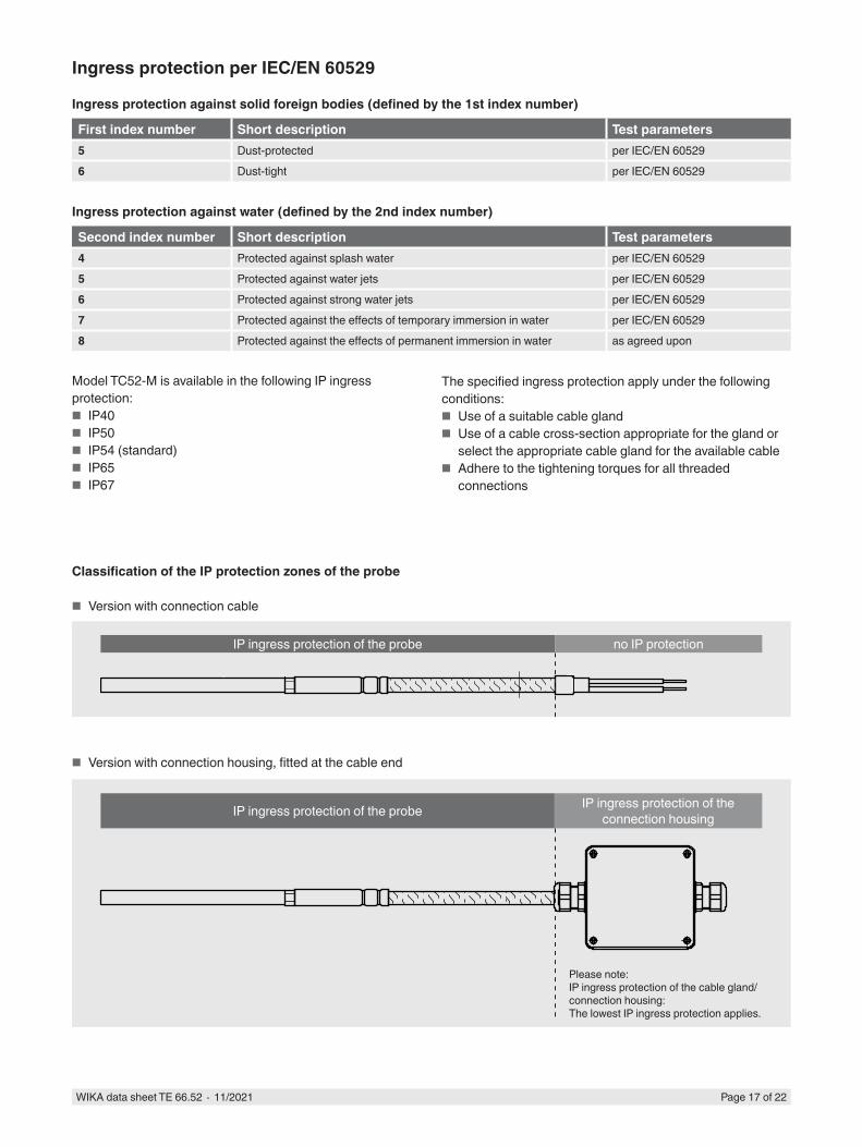
Ingress protection per IEC/EN 60529
Ingress protection against solid foreign bodies (defined by the 1st index number)
First index number Short description Test parameters5 Dust-protected per IEC/EN 605296 Dust-tight per IEC/EN 60529
Ingress protection against water (defined by the 2nd index number)
Second index number Short description Test parameters4 Protected against splash water per IEC/EN 605295 Protected against water jets per IEC/EN 605296 Protected against strong water jets per IEC/EN 605297 Protected against the effects of temporary immersion in water per IEC/EN 605298 Protected against the effects of permanent immersion in water as agreed upon
Model TC52-M is available in the following IP ingress protection:
■ IP40 ■ IP50 ■ IP54 (standard) ■ IP65 ■ IP67
Classification of the IP protection zones of the probe
■ Version with connection cable
■ Version with connection housing, fitted at the cable end
W LA
Ød T
3162371.03
W LA
Ød T
3162371.03
W LA
Ød T
3162371.03
IP ingress protection of the probe no IP protection
IP ingress protection of the probe IP ingress protection of the connection housing
Please note:IP ingress protection of the cable gland/connection housing:The lowest IP ingress protection applies.
The specified ingress protection apply under the following conditions:
■ Use of a suitable cable gland ■ Use of a cable cross-section appropriate for the gland or
select the appropriate cable gland for the available cable ■ Adhere to the tightening torques for all threaded
connections
Page 18 of 22WIKA data sheet TE 66.52 ∙ 11/2021
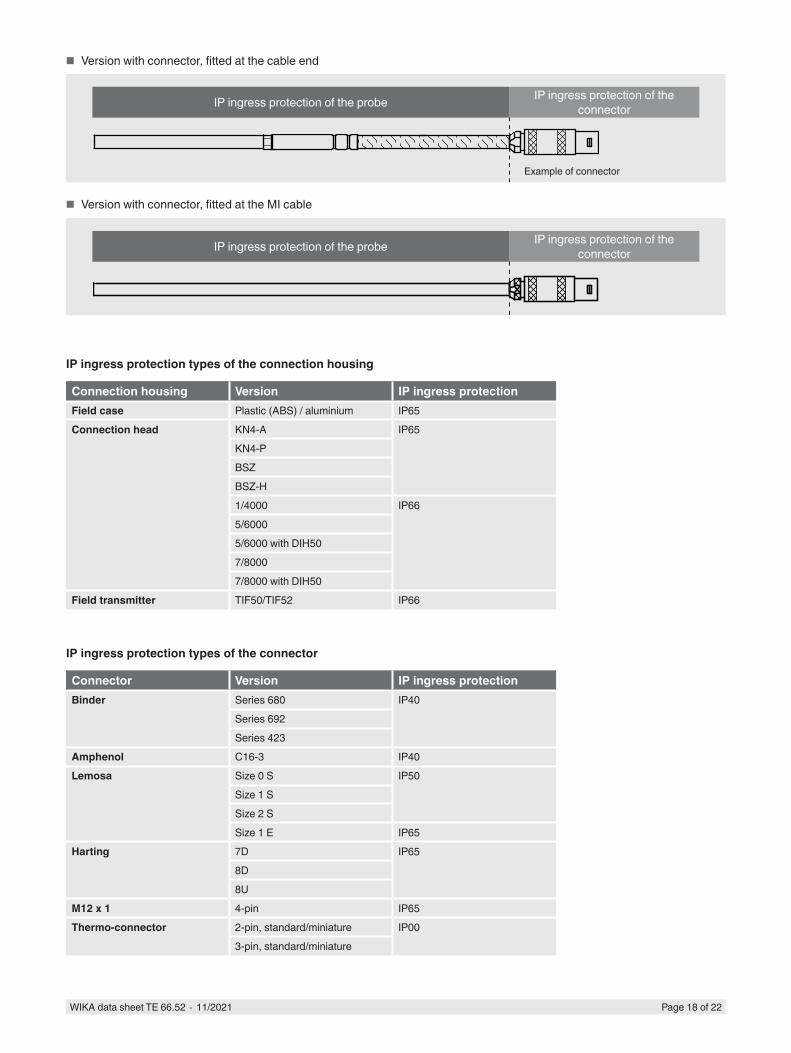
■ Version with connector, fitted at the cable end
■ Version with connector, fitted at the MI cable
IP ingress protection types of the connection housing
Connection housing Version IP ingress protectionField case Plastic (ABS) / aluminium IP65Connection head KN4-A IP65
KN4-PBSZBSZ-H1/4000 IP665/60005/6000 with DIH507/80007/8000 with DIH50
Field transmitter TIF50/TIF52 IP66
IP ingress protection types of the connector
Connector Version IP ingress protectionBinder Series 680 IP40
Series 692Series 423
Amphenol C16-3 IP40Lemosa Size 0 S IP50
Size 1 SSize 2 SSize 1 E IP65
Harting 7D IP658D8U
M12 x 1 4-pin IP65Thermo-connector 2-pin, standard/miniature IP00
3-pin, standard/miniature
WAT
3160700.03
Ød
WAT
3160700.03
Ød
WAT
3160700.03
Ød IP ingress protection of the probe IP ingress protection of the connector
Example of connector
A
ØdA
Ød IP ingress protection of the probe IP ingress protection of the connector

Page 19 of 22WIKA data sheet TE 66.52 ∙ 11/2021
Electrical connectionWithout connector
Lemosa connectormax. permissible temperature range: -55 ... +250 °C [-67... +482 °F]
Screw/plug-in connector (Amphenol, Binder)Series 680, series 423 (shielded)max. permissible temperature range: -40 ... +85 °C [-40 ... +185 °F]
3366
142.
083374
896.
0131
7196
6.01Single
thermocouple
Dual thermocouple
Single thermocouple
Dual thermocouple
Single thermocouple
Dual thermocouple
Direction of view
Direction of view
23
41
4
3
4
3
4
2
2
1
25
61
1
2
Stecker (male) Kupplung (female)
Ansicht auf Steckerkontakte Ansicht auf Buchsenkontakte
2
1
3
4
2
1
3
4
2
1
3
4
2
1
3
4
3
4
2
1
3
4
2
1
3
4
2
1
3
4
2
1
2
3
5
4
1 6
5
4
2
3
6 1
Serie 691Binder
1
2
34
5
6
7
12
12-polig1
2
34
5
6
7
12
8
9
10
11
8
9
10
11
Stecker (male) Kupplung (female)
Ansicht auf Steckerkontakte Ansicht auf Buchsenkontakte
Ansichtsrichtung Ansichtsrichtung
C16-3Amphenol
1
4
3
5
6 7
2
8
3
5
1
4
7 6
2
8
8
4
6
35
7
1
2
BinderSerie 680Serie 423 geschirmt
BinderSerie 680Serie 423 geschirmt
BinderSerie 680Serie 423 geschirmt
BinderSerie 680Serie 423 geschirmt
BinderSerie 692
1
4
3
2
1
2+-
+-+-
Stecker (male) Kupplung (female)
Serie 680Binder
Serie 680Binder
2
14
3 2
1 4
3
2
14
3 2
1 4
3
Ansicht auf Steckerkontakte Ansicht auf Buchsenkontakte
Ansichtsrichtung AnsichtsrichtungAnsichtsrichtung Ansichtsrichtung
2
3
5
4
1
6
5
42
3
6
1
BinderSerie 423Serie 423 geschirmt
.3366142 08

23
41
3
4
3
4
2
2
1
1
2
Ansicht auf Steckerkontakte
3
2
4
1
Binder Schraub-/Steckverbinder Serie 713 M12x1
3
2
4
1
3
2
4
1
3
2
4
1
57
6
3
2
1
2
31
1
6
25
2
1
3
7
68
42
524
131
4
5
6 7 8
1 2
33
2 1
8 7
4
5
6 ( )( )
Achtung: Anschlussbelegung ausschließlich für WIKA Standard!
Kontakteinsatz BuchseKontakteinsatz Stifte
-
+
-
+
-
+
-
+
+
-
+
-
8
8
47
32
1
47
3
4
3
4
5
6 7 8
1 2
33
2 1
8 7
4
5
6 ( )( )
Achtung: Anschlussbelegung ausschließlich für WIKA Standard!
Kontakteinsatz BuchseKontakteinsatz Stifte
1437
2358
.01
57
6
3
2
1
2
31
1
6
25
2
1
3
7
68
42
524
131
4
5
6 7 8
1 2
33
2 1
8 7
4
5
6 ( )( )
Achtung: Anschlussbelegung ausschließlich für WIKA Standard!
Kontakteinsatz BuchseKontakteinsatz Stifte
-
+
-
+
-
+
-
+
+
-
+
-
8
8
47
32
1
47
3
4
3
4
5
6 7 8
1 2
33
2 1
8 7
4
5
6 ( )( )
Achtung: Anschlussbelegung ausschließlich für WIKA Standard!
Kontakteinsatz BuchseKontakteinsatz Stifte
Page 20 of 22WIKA data sheet TE 66.52 ∙ 11/2021
Thermo-connector (male)
Binder screw/plug-in connector (male), M12 x 1 (series 713)
Harting connector
1437
2219
.01
Contact insert socket
ATTENTION: Pin assignment for version “WIKA standard”!
Contact insert pins
1437
2213
.01
Positive and negative terminal are marked.Two thermo-connectors are used with dual thermocouples.
1
4
3
2
1
2+-
+-+- 2
31
2
1
Stecker (male) Kupplung (female)
1
4
3
2
1
2+-
+-+- 2
31
2
1
Stecker (male) Kupplung (female)
1
4
3
2
1
2+-
+-+- 2
31
2
1
Stecker (male) Kupplung (female)
Direction of viewDirection of view

Page 21 of 22WIKA data sheet TE 66.52 ∙ 11/2021
Single thermocouple
Rack-mounting terminals
1438
2009
.01
Dual thermocouple
21 21 3 21 3 4 21 3 4 21 3 4
45
6
2
3
1
3
21 1
4
23
2
12
6
78
43
534
121
-
+
-
+
-
+
-
+
+
-
+
-
8
3 47
32
1
14
2
1
2
Anschlussbelegung Reihenklemmen1xPT... 2, 3 und 4-Leiterschasltung
21 3 45 6 5 6 7 8
Anschlussbelegung Reihenklemmen2xPT... 2, 3 und 4-Leiterschasltung
21 21 3 4 21 3 4 5 6
Anschlussbelegung ReihenklemmenThermoelement
The colour coding at the positive connection to the instruments always decides the correlation of polarity and connection terminal.
For the electrical connections of built-in temperature transmitters see the corresponding data sheets or operating instructions.
+
-
+
-
-
+
Ceramic terminal block
Crastin terminal block
Single thermocouple
Single thermocouple
Dual thermocouple
Dual thermocouple

WIKA Alexander Wiegand SE & Co. KGAlexander-Wiegand-Straße 3063911 Klingenberg/GermanyTel. +49 9372 132-0Fax +49 9372 [email protected]
11/2
021
EN Page 22 of 22WIKA data sheet TE 66.52 ∙ 11/2021
Operating conditions
Mechanical requirements
VersionStandard max. 50 g peak-to-peak, 10 ... 500 Hz
The information on vibration resistance refers to the probe tip.
Storage temperature-40 ... +80 °C [-40 ... +176 °F]
Other storage temperatures on request
Shipping information
Model TC52-M thermocouple in “straight” version, with lengths > 1,100 mm [43.31 in] is wound and delivered in coils.
Certificates (option)
Certification type Measurement accuracy
Material certificate
2.2 test report x x3.1 inspection certificate x xDAkkS calibration certificate x -
The different certifications can be combined with each other.
The thermometer is immersed in a calibrator without process connection.
© 11/2021 WIKA Alexander Wiegand SE & Co. KG, all rights reserved.The specifications given in this document represent the state of engineering at the time of publishing.We reserve the right to make modifications to the specifications and materials.
Ordering informationModel / Explosion protection / Probe version / Threaded connection version / Thread size / Materials / Probe diameter / Measuring element / Connection method / Temperature range / Connection cable, jacket / Lead ends version / Certificates / Options