Embed Size (px)
Citation preview
Magnetic Resonance Imaging
PHYS Lecture
Carlos Vinhais
Departamento de FísicaInstituto Superior de Engenharia do Porto
Carlos Vinhais 2
Overview
• Physics of NMR
• The NMR Experiment
• Longitudinal Magnetization• T1 Relaxation• T1-weighted Contrast
• Transversal Magnetization• T2 Relaxation• T2-weighted Contrast• T2 and T2* Relaxation
• Image Contrast• T1-weighted• Proton Density• T2-weighted• T2-FLAIR
• Spin Echo• Pulse Sequence Diagrams• Basic Pulse Sequences• Other Concepts
• MR Image Examples
Carlos Vinhais 3
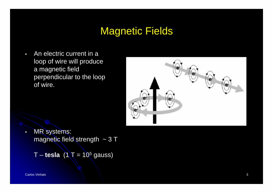
Magnetic Fields
• An electric current in aloop of wire will producea magnetic field perpendicular to the loopof wire.
• MR systems: magnetic field strength ~ 3 T
T – tesla (1 T = 105 gauss)
Carlos Vinhais 4
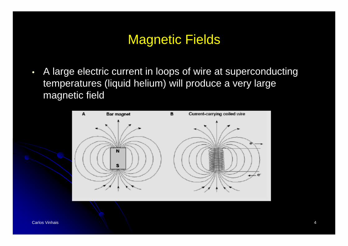
Magnetic Fields
• A large electric current in loops of wire at superconducting temperatures (liquid helium) will produce a very large magnetic field
Carlos Vinhais 5
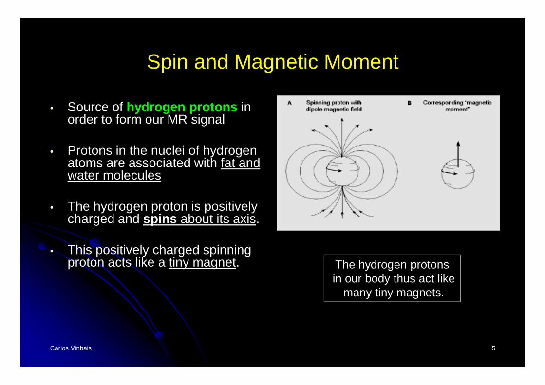
Spin and Magnetic Moment
• Source of hydrogen protons in order to form our MR signal
• Protons in the nuclei of hydrogen atoms are associated with fat and water molecules
• The hydrogen proton is positively charged and spins about its axis.
• This positively charged spinning proton acts like a tiny magnet. The hydrogen protons
in our body thus act likemany tiny magnets.
Carlos Vinhais 6
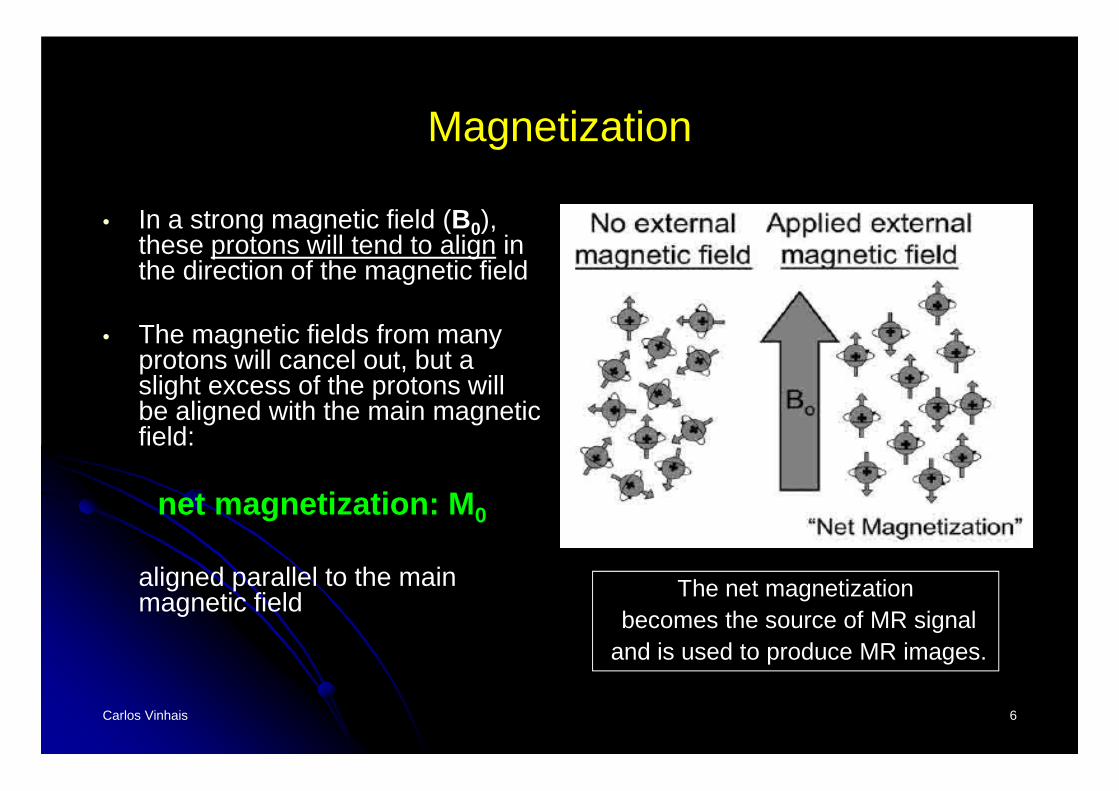
Magnetization
• In a strong magnetic field (B0), these protons will tend to align in the direction of the magnetic field
• The magnetic fields from many protons will cancel out, but a slight excess of the protons will be aligned with the main magnetic field:
net magnetization: M 0
aligned parallel to the main magnetic field The net magnetization
becomes the source of MR signaland is used to produce MR images.
Carlos Vinhais 7
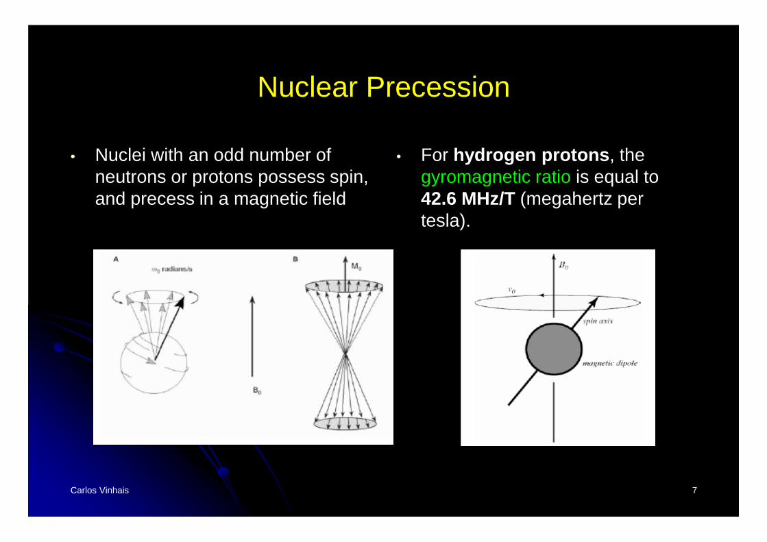
Nuclear Precession
• Nuclei with an odd number of neutrons or protons possess spin, and precess in a magnetic field
• For hydrogen protons , the gyromagnetic ratio is equal to 42.6 MHz/T (megahertz per tesla).
Carlos Vinhais 8
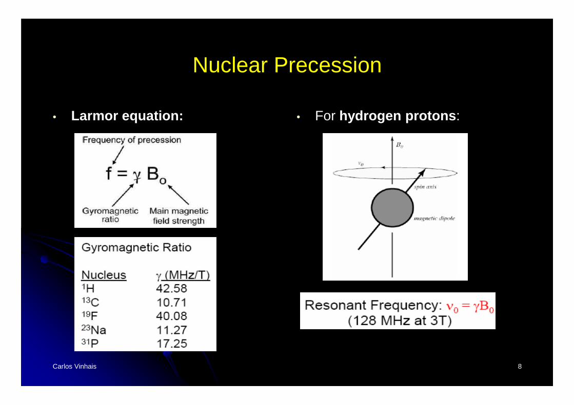
Nuclear Precession
• Larmor equation: • For hydrogen protons :
Carlos Vinhais 9
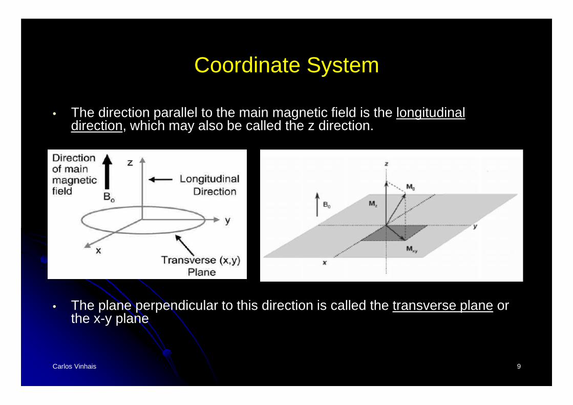
Coordinate System
• The direction parallel to the main magnetic field is the longitudinal direction, which may also be called the z direction.
• The plane perpendicular to this direction is called the transverse plane or the x-y plane
Carlos Vinhais 10
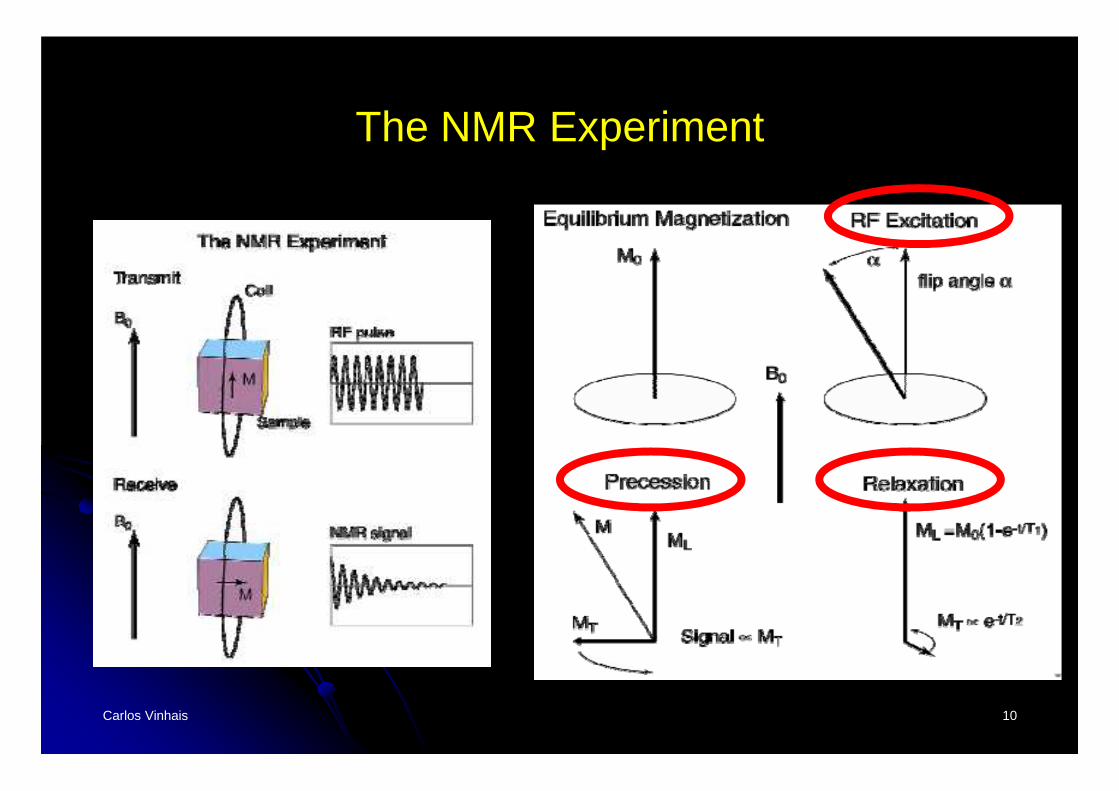
The NMR Experiment
Carlos Vinhais 11
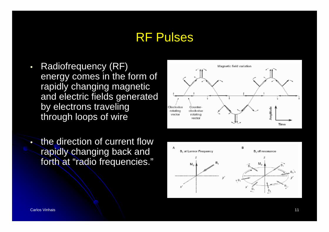
RF Pulses
• Radiofrequency (RF) energy comes in the form of rapidly changing magnetic and electric fields generated by electrons traveling through loops of wire
• the direction of current flow rapidly changing back and forth at “radio frequencies.”
Carlos Vinhais 12
RF Pulses
• For the MR system, this RF energy is transmitted by an RF transmit coil (eg, body coil, head coil, knee coil).
• Typically, the RF is transmitted for a short period of time: RF pulse
• This transmitted RF pulse must be at the precessional frequency of the protons, in order for resonance to occur and for efficient transfer of energy from the RF coil to the protons.
Carlos Vinhais 13
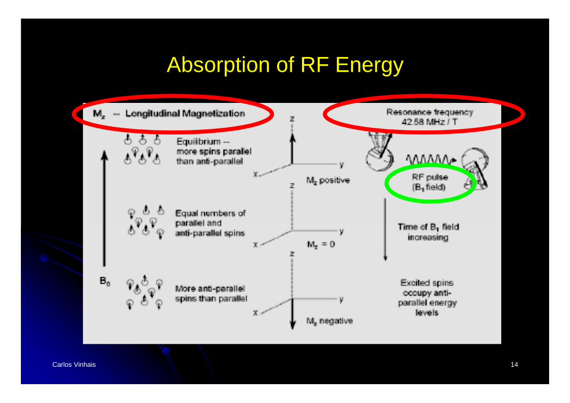
Absorption of RF Energy
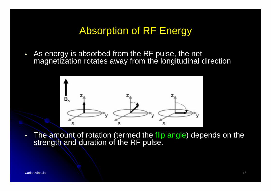
• As energy is absorbed from the RF pulse, the net magnetization rotates away from the longitudinal direction
• The amount of rotation (termed the flip angle) depends on the strength and duration of the RF pulse.
Carlos Vinhais 14
Absorption of RF Energy
Carlos Vinhais 15
Absorption of RF Energy
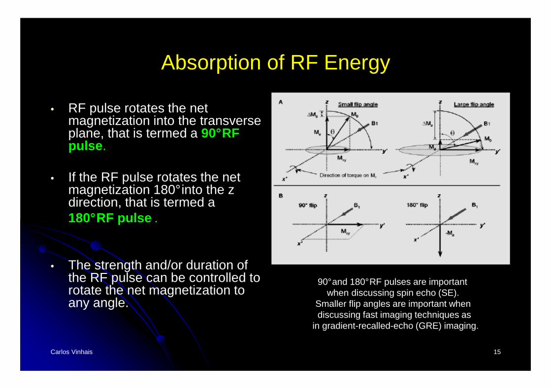
• RF pulse rotates the net magnetization into the transverse plane, that is termed a 90°RF pulse .
• If the RF pulse rotates the net magnetization 180°into the z direction, that is termed a180°RF pulse .
• The strength and/or duration of the RF pulse can be controlled to rotate the net magnetization to any angle.
90°and 180°RF pulses are importantwhen discussing spin echo (SE).
Smaller flip angles are important when discussing fast imaging techniques as
in gradient-recalled-echo (GRE) imaging.
Carlos Vinhais 16
Longitudinal Magnetization
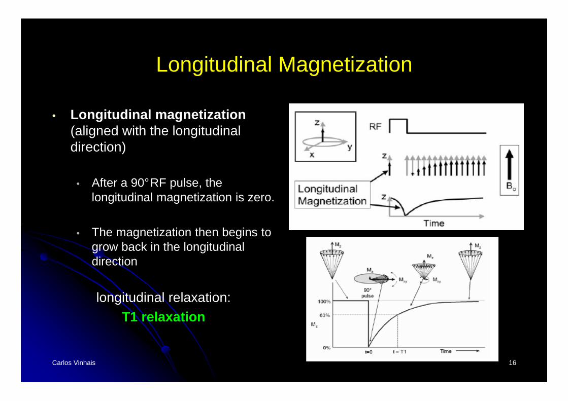
• Longitudinal magnetization(aligned with the longitudinal direction)
• After a 90°RF pulse, the longitudinal magnetization is zero.
• The magnetization then begins to grow back in the longitudinal direction
longitudinal relaxation:T1 relaxation
Carlos Vinhais 17
T1 Relaxation
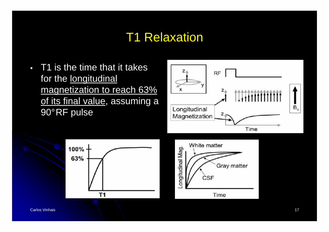
• T1 is the time that it takes for the longitudinal magnetization to reach 63% of its final value, assuming a 90°RF pulse
Carlos Vinhais 18
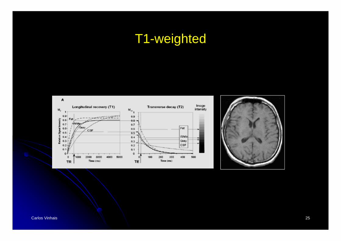
T1-weighted Contrast
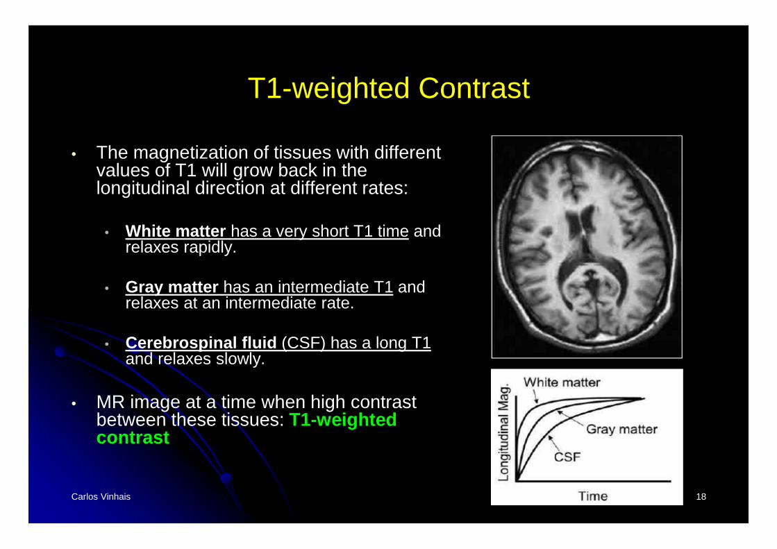
• The magnetization of tissues with different values of T1 will grow back in the longitudinal direction at different rates:
• White matter has a very short T1 time and relaxes rapidly.
• Gray matter has an intermediate T1 and relaxes at an intermediate rate.
• Cerebrospinal fluid (CSF) has a long T1and relaxes slowly.
• MR image at a time when high contrast between these tissues: T1-weighted contrast
Carlos Vinhais 19
Transversal Magnetization
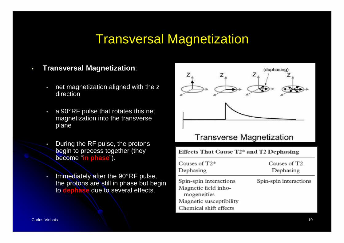
• Transversal Magnetization :
• net magnetization aligned with the z direction
• a 90°RF pulse that rotates this net magnetization into the transverse plane
• During the RF pulse, the protons begin to precess together (they become “in phase ”).
• Immediately after the 90°RF pulse, the protons are still in phase but begin to dephase due to several effects.
Carlos Vinhais 20
T2 Relaxation
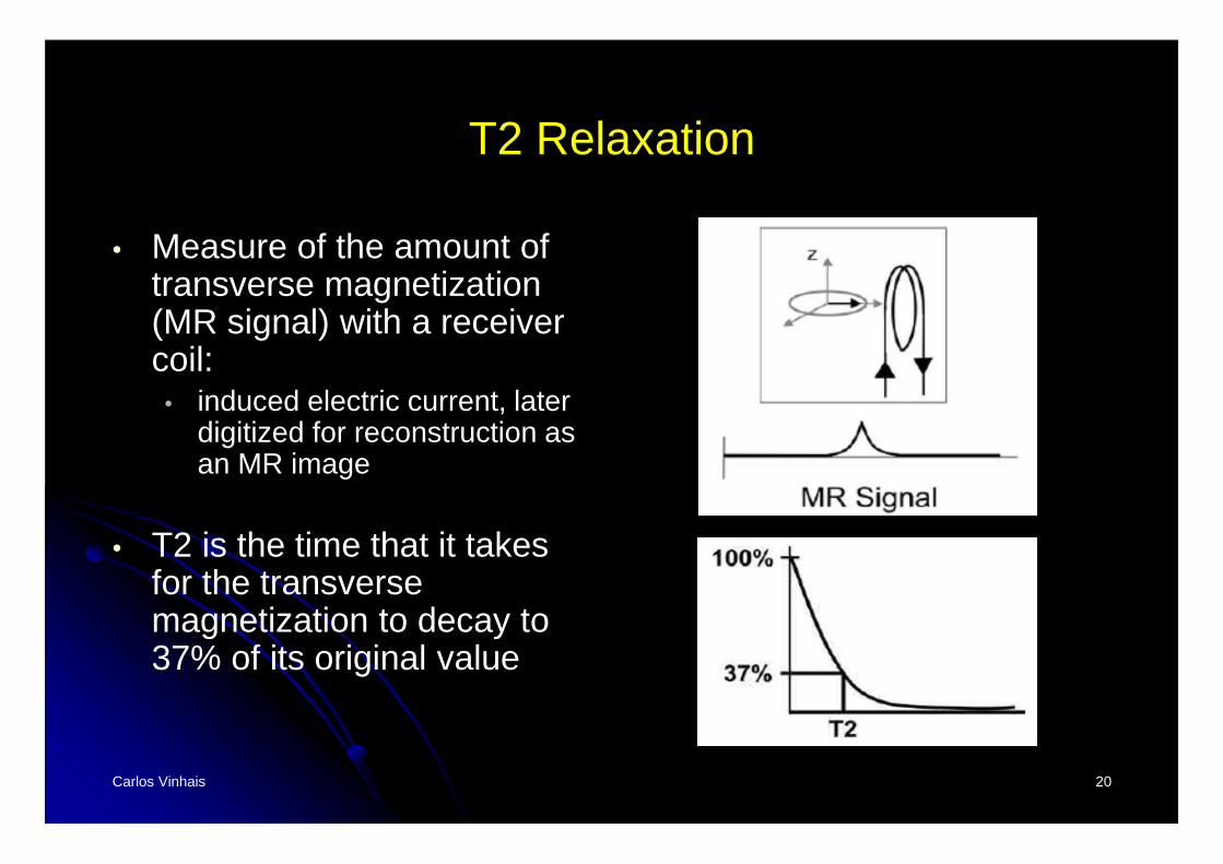
• Measure of the amount of transverse magnetization (MR signal) with a receiver coil:
• induced electric current, later digitized for reconstruction as an MR image
• T2 is the time that it takes for the transverse magnetization to decay to 37% of its original value
Carlos Vinhais 21
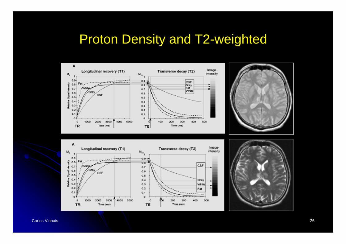
T2-weighted Contrast
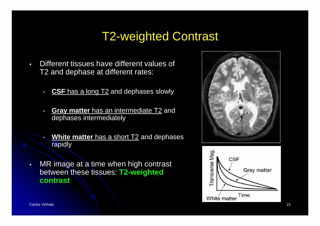
• Different tissues have different values of T2 and dephase at different rates:
• CSF has a long T2 and dephases slowly
• Gray matter has an intermediate T2 and dephases intermediately
• White matter has a short T2 and dephases rapidly
• MR image at a time when high contrast between these tissues: T2-weighted contrast
Carlos Vinhais 22
T2 and T2* Relaxation
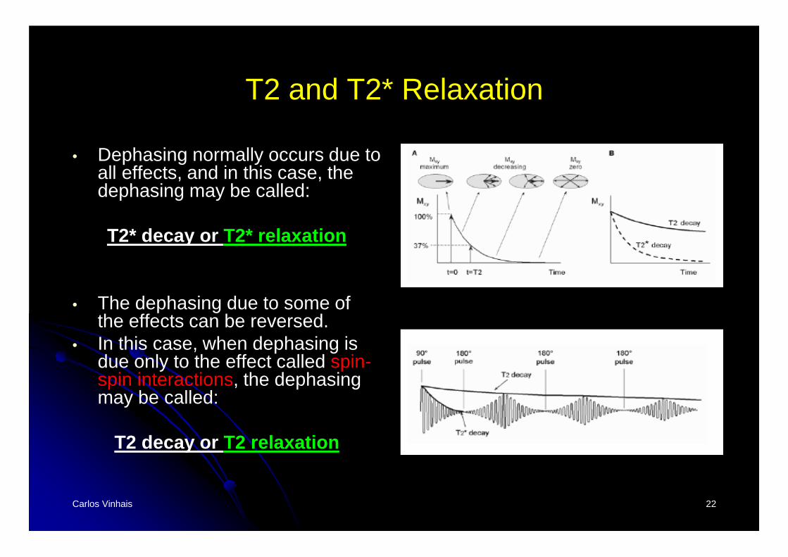
• Dephasing normally occurs due to all effects, and in this case, the dephasing may be called:
T2* decay or T2* relaxation
• The dephasing due to some of the effects can be reversed.
• In this case, when dephasing is due only to the effect called spin-spin interactions, the dephasing may be called:
T2 decay or T2 relaxation
Carlos Vinhais 23
T1 vs T2 Relaxation
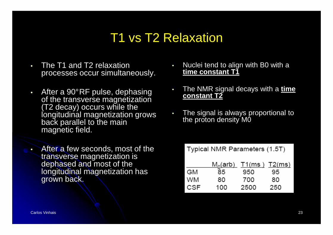
• The T1 and T2 relaxation processes occur simultaneously.
• After a 90°RF pulse, dephasing of the transverse magnetization (T2 decay) occurs while the longitudinal magnetization grows back parallel to the main magnetic field.
• After a few seconds, most of the transverse magnetization is dephased and most of the longitudinal magnetization has grown back.
• Nuclei tend to align with B0 with a time constant T1
• The NMR signal decays with a time constant T2
• The signal is always proportional to the proton density M0
Carlos Vinhais 24
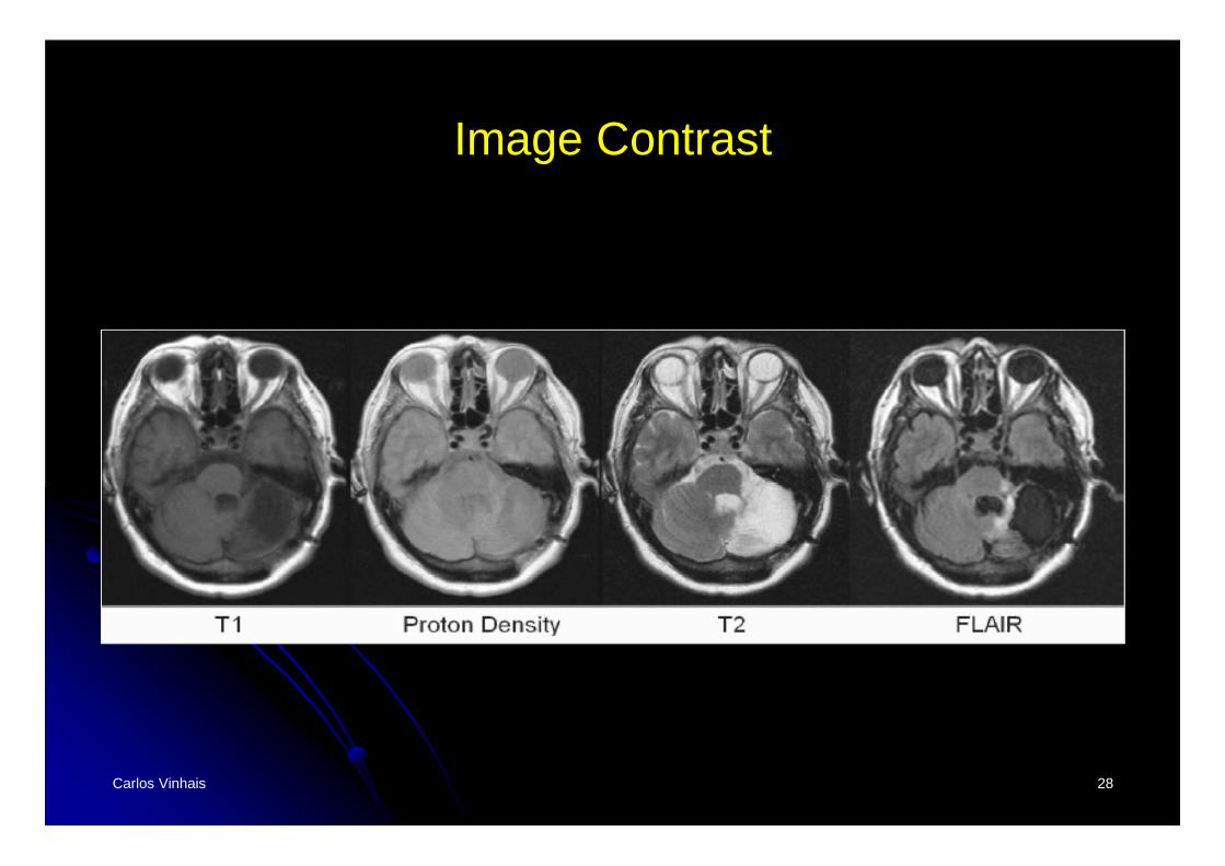
Image Contrast
• MR imaging is to create images that have certain contrasts. Longitudinal and transverse magnetizations relax due to T1 and T2 effects
• TE and TR can be used to control the amount of “weighting” of these effects in our image:
• T2 effects are minimized and T1 effects are maximized:T1-weighted image
• T1 effects are minimized and T2 effects are maximized:T2-weighted image
• If both T1 and T2 effects are minimized:image with “proton density” or “spin density” weighting
Carlos Vinhais 25
T1-weighted
Carlos Vinhais 26
Proton Density and T2-weighted
Carlos Vinhais 27
T2 - FLAIR
Fluid Attenuated Inversion Recovery
• FLAIR images are T2-weighted with the CSF signal suppressed
• Application: MS Lesion Segmentation:“An Automatic Segmentation of T2-FLAIR Multiple Sclerosis Lesions”, IJ - 2008 MICCAI Workshop
• http://www.midasjournal.org/browse/publication/284• http://www.midasjournal.org/browse/journal/18
Carlos Vinhais 28
Image Contrast
Carlos Vinhais 29
Spin Echo
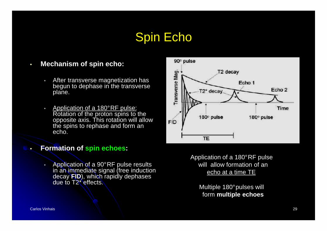
• Mechanism of spin echo:
• After transverse magnetization has begun to dephase in the transverse plane.
• Application of a 180°RF pulse: Rotation of the proton spins to the opposite axis. This rotation will allow the spins to rephase and form an echo.
• Formation of spin echoes :
• Application of a 90°RF pulse results in an immediate signal (free induction decay FID), which rapidly dephases due to T2* effects.
Application of a 180°RF pulsewill allow formation of an
echo at a time TE
Multiple 180°pulses willform multiple echoes
Carlos Vinhais 30
Pulse Sequence Diagrams
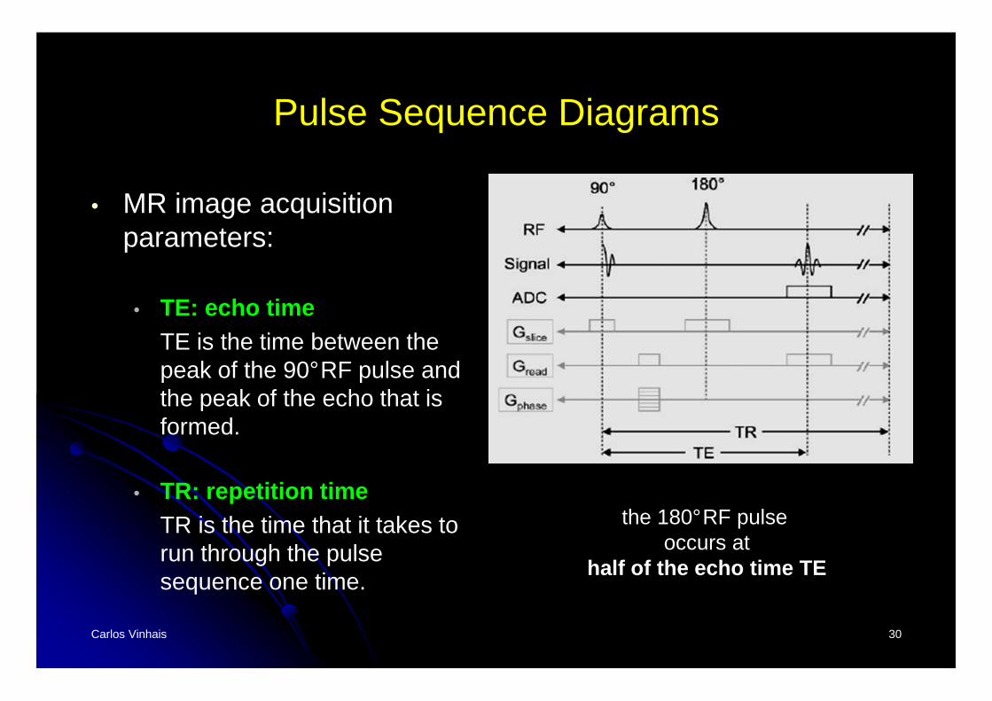
• MR image acquisition parameters:
• TE: echo timeTE is the time between the peak of the 90°RF pulse and the peak of the echo that is formed.
• TR: repetition timeTR is the time that it takes to run through the pulse sequence one time.
the 180°RF pulseoccurs at
half of the echo time TE
Carlos Vinhais 31
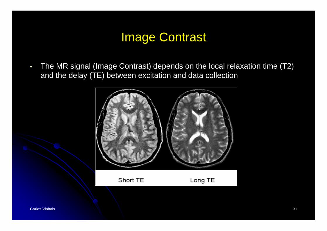
Image Contrast
• The MR signal (Image Contrast) depends on the local relaxation time (T2) and the delay (TE) between excitation and data collection
Carlos Vinhais 32
Basic Pulse Sequences
• Spin Echo• Multi-echo Spin Echo• Turbo Spin Echo• Inversion Recovery• Gradient Recalled Echo
• Advanced Imaging Methods• Fast spin echo• Echo planar• spiral
Carlos Vinhais 33
Other Concepts
• Gradient Fields • Slice Selection• Frequency Encoding• Phase Encoding• K-Space
Carlos Vinhais 34
MR Image Examples
Carlos Vinhais 35
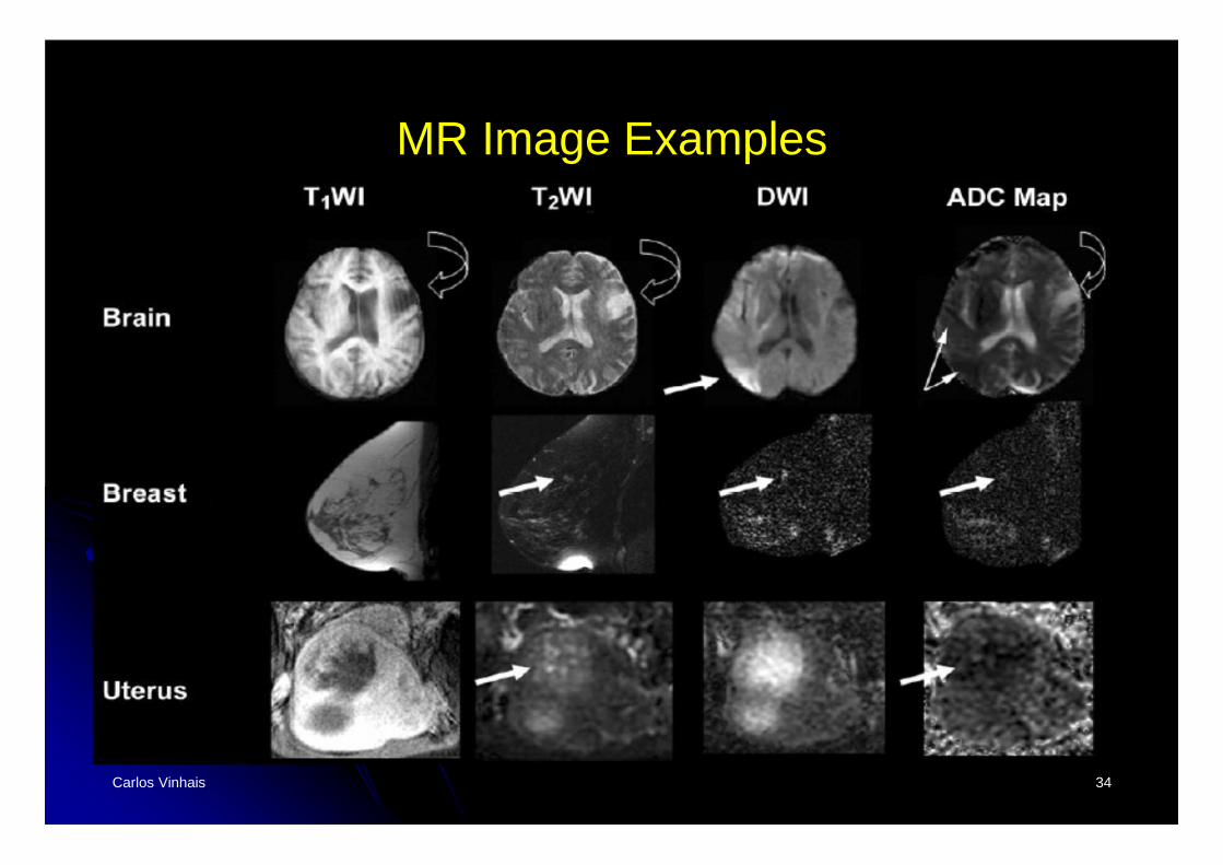
MR Image Examples
• Examples demonstrate the versatility of MR imaging in producing different image contrasts.
• T1-weighted images (T1WI)• T2-weighted images (T2WI)• Diffusion-weighted images (DWI)• Maps of Apparent Diffusion Coefficient (ADC) of water.
Carlos Vinhais 36
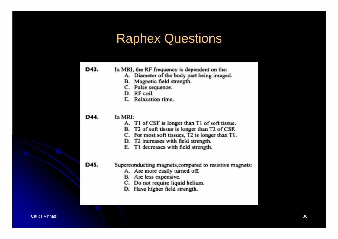
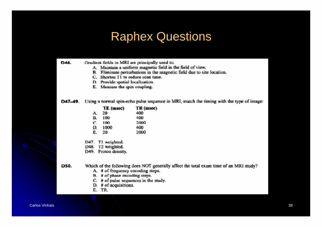
Raphex Questions
Carlos Vinhais 37
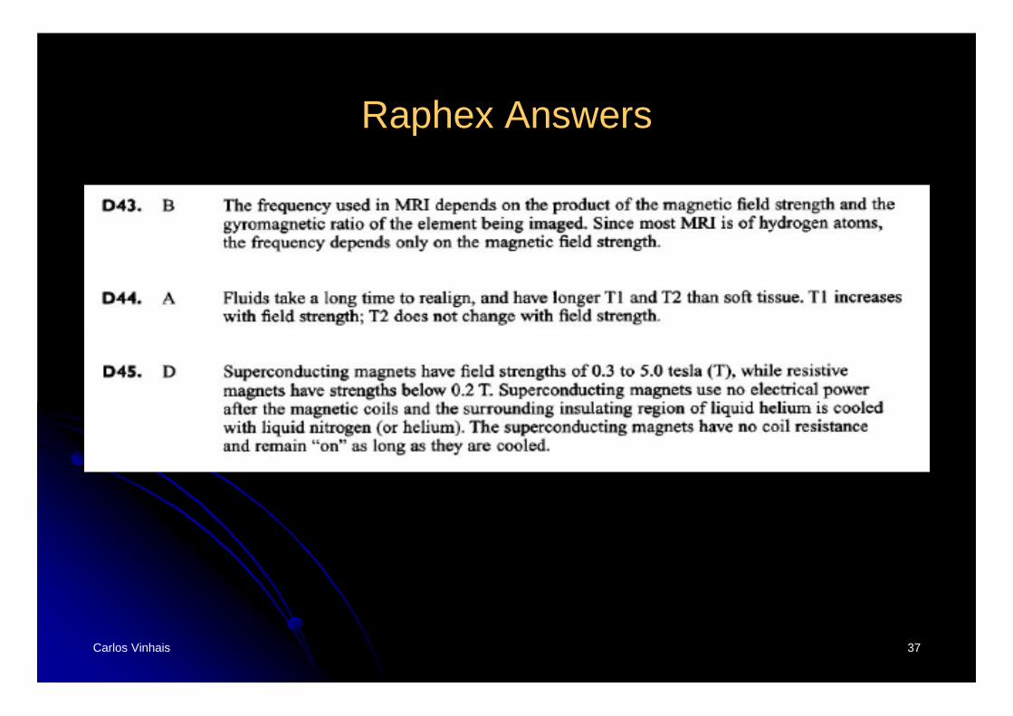
Raphex Answers
Carlos Vinhais 38
Raphex Questions
Carlos Vinhais 39
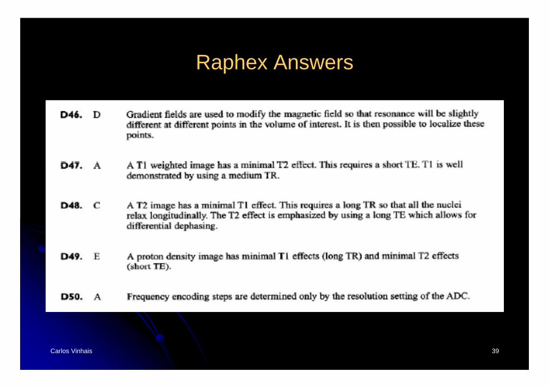
Raphex Answers
End of Lecture!