Embed Size (px)
Citation preview

Journal of the Korean Physical Society, Vol. 63, No. 7, October 2013, pp. 0∼0
Magnet Design for the 10MeV AVF Cyclotron Accelerator
R. Solhju and H. Afarideh∗
Department of Nuclear Engineering & Physics, Amirkabir University of Technology, Tehran 15875-4413, Iran
M. Ghergherehchi† and J. S. Chai
School of Information & Communication Engineering,Sungkyunkwan University, Suwon 440-746, Korea
(Received 26 December 2013, in final form 28 May 2013)
In this paper, an azimuthally varying field (AVF) magnet is designed to produce a 10 MeV protonbeam. In order to design and analyze the magnet three-dimensionally, we use the CST program.Also, field mapping results have been obtained by using the CST program and the MATLABprogram to validate the precision of the design. In addition, an iterative process is conducted formagnet shimming. The precision of this design is ensured by using the optimization part of CSTto optimize parameters like the number of mesh cells, the boundary dimension, etc.
PACS numbers: 42.30.R, 42.40.Ht, 42.30.KqKeywords: Cyclotron, AVF magnet, Magnet designDOI: 10.3938/jkps.63.0
I. INTRODUCTION
A design study of a 10 MeV cyclotron was started inMarch 2012 at Amirkabir University of Technology. Themain purpose of this baby cyclotron is to produce a pro-ton beam for producing radio isotopes for positron emis-sion tomography (PET), as well as fluorodeoxyglucoseFDG.
The design study of the 10 MeV cyclotron magnets isdescribed in this paper. A magnet of this medical accel-erator is made of steel-1008 with 4 sectors. The lowerpart of the magnet is shown in Fig. 1. The diameter andthe height of the magnet are 1.58 m and 0.86 m, respec-tively and the pole radius is 0.45 m. The top and thebottom yokes of the magnet have one hole at each valleyfor the RF system, vacuum pumps and other subsystemdevices. The maximum field on the mid-plane is 1.93 T.Other magnet specifications are shown in Table 1.
Three steps were taken to obtain an isochronous mag-netic field: basic calculations, 3D simulations using thecomputerized simulation technique (CST) program [1],and optimization. One of the advantages of this designis the optimization of different parameters by sweepingthem one by one. The number of mesh cells, the yokewidth, and the number of ampere-turns are among theseparameters.
∗E-mail: [email protected]; Fax: +98-21-6649-5519†E-mail: [email protected]; Fax: +82-31-299-4667
II. MAGNET DESIGN
All the calculations were based on the fact that thecentral magnetic field and RF frequency depend on eachother, so the harmonic number and the RF frequencywere set before the calculations of magnetic rigidity andthe extraction radius. A value of 0.458 T-m for the mag-net rigidity is needed at the extraction radius where theproton beam energy is 10 MeV. The RF frequency is setto 69 MHz, so the central field of the magnet should be1.1306 T [2]. Also, according to the RF frequency andthe harmonic number, the ion extraction position canbe determined by using an equilibrium-orbit calculation.Based on these calculations, the particle’s energy shouldreach 10 MeV at an extraction radius of 0.40 m.
Low carbon steel, ANSI 1008, was considered to bethe material of the magnet. This material has a highersaturation point than ANSI 1010, but it is smoother andmay have some difficulties in machining. According tothe saturation point of the material, other parameters,such as the magnetic field at the hill part, the valley gap,the hill gap and the return yoke radius, were assumed.Also, the number of ampere-turns was determined byusing Ampere’s law initially [2] and then by sweeping onit in the sweep part of the CST for optimization.
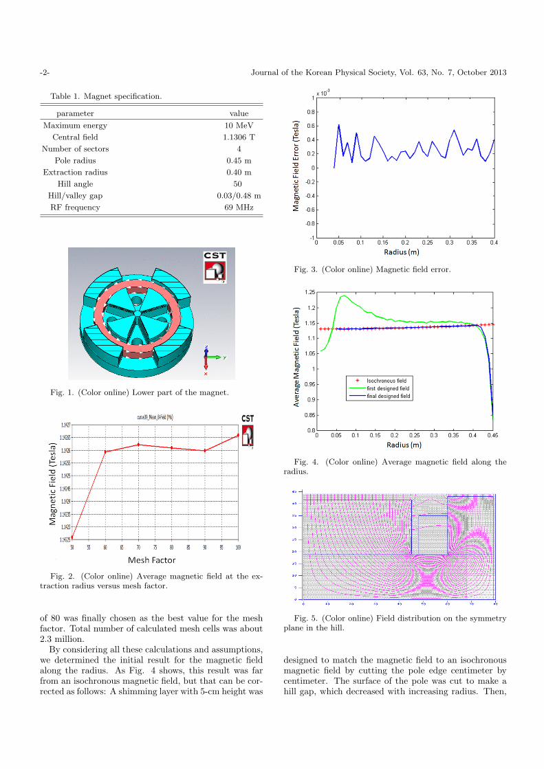
The number of mesh cells plays an important role inthe accuracy of the simulation. Figure 2 shows the av-erage magnetic field at the extraction radius versus themesh factor. The intensity of the average magnetic fielddoes not change for mesh factors higher than 70. Thisparameter was investigated at other radii’s and the value
-1-
-2- Journal of the Korean Physical Society, Vol. 63, No. 7, October 2013
Table 1. Magnet specification.
parameter value
Maximum energy 10 MeV
Central field 1.1306 T
Number of sectors 4
Pole radius 0.45 m
Extraction radius 0.40 m
Hill angle 50
Hill/valley gap 0.03/0.48 m
RF frequency 69 MHz
Fig. 1. (Color online) Lower part of the magnet.
Fig. 2. (Color online) Average magnetic field at the ex-traction radius versus mesh factor.
of 80 was finally chosen as the best value for the meshfactor. Total number of calculated mesh cells was about2.3 million.
By considering all these calculations and assumptions,we determined the initial result for the magnetic fieldalong the radius. As Fig. 4 shows, this result was farfrom an isochronous magnetic field, but that can be cor-rected as follows: A shimming layer with 5-cm height was
Fig. 3. (Color online) Magnetic field error.
Fig. 4. (Color online) Average magnetic field along theradius.
Fig. 5. (Color online) Field distribution on the symmetryplane in the hill.
designed to match the magnetic field to an isochronousmagnetic field by cutting the pole edge centimeter bycentimeter. The surface of the pole was cut to make ahill gap, which decreased with increasing radius. Then,
Magnet Design for the 10MeV AVF Cyclotron Accelerator – R. Solhju et al. -3-
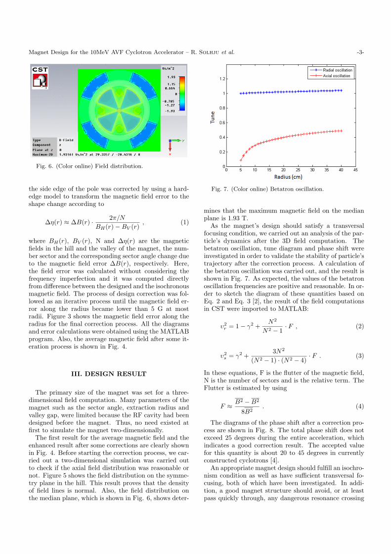
Fig. 6. (Color online) Field distribution.
the side edge of the pole was corrected by using a hard-edge model to transform the magnetic field error to theshape change according to
∆η(r) ≈ ∆B(r) · 2π/N
BH(r)−BV (r), (1)
where BH(r), BV (r), N and ∆η(r) are the magneticfields in the hill and the valley of the magnet, the num-ber sector and the corresponding sector angle change dueto the magnetic field error ∆B(r), respectively. Here,the field error was calculated without considering thefrequency imperfection and it was computed directlyfrom difference between the designed and the isochronousmagnetic field. The process of design correction was fol-lowed as an iterative process until the magnetic field er-ror along the radius became lower than 5 G at mostradii. Figure 3 shows the magnetic field error along theradius for the final correction process. All the diagramsand error calculations were obtained using the MATLABprogram. Also, the average magnetic field after some it-eration process is shown in Fig. 4.
III. DESIGN RESULT
The primary size of the magnet was set for a three-dimensional field computation. Many parameters of themagnet such as the sector angle, extraction radius andvalley gap, were limited because the RF cavity had beendesigned before the magnet. Thus, no need existed atfirst to simulate the magnet two-dimensionally.
The first result for the average magnetic field and theenhanced result after some corrections are clearly shownin Fig. 4. Before starting the correction process, we car-ried out a two-dimensional simulation was carried outto check if the axial field distribution was reasonable ornot. Figure 5 shows the field distribution on the symme-try plane in the hill. This result proves that the densityof field lines is normal. Also, the field distribution onthe median plane, which is shown in Fig. 6, shows deter-
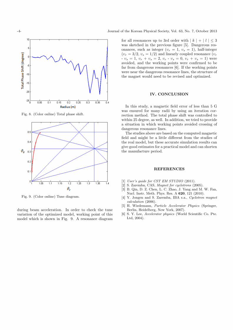
Fig. 7. (Color online) Betatron oscillation.
mines that the maximum magnetic field on the medianplane is 1.93 T.
As the magnet’s design should satisfy a transversalfocusing condition, we carried out an analysis of the par-ticle’s dynamics after the 3D field computation. Thebetatron oscillation, tune diagram and phase shift wereinvestigated in order to validate the stability of particle’strajectory after the correction process. A calculation ofthe betatron oscillation was carried out, and the result isshown in Fig. 7. As expected, the values of the betatronoscillation frequencies are positive and reasonable. In or-der to sketch the diagram of these quantities based onEq. 2 and Eq. 3 [2], the result of the field computationsin CST were imported to MATLAB:
υ2r = 1− γ2 +
N2
N2 − 1· F , (2)
υ2s = γ2 +
3N2
(N2 − 1) · (N2 − 4)· F . (3)
In these equations, F is the flutter of the magnetic field,N is the number of sectors and is the relative term. TheFlutter is estimated by using
F ≈ B2 −B2
8B2. (4)
The diagrams of the phase shift after a correction pro-cess are shown in Fig. 8. The total phase shift does notexceed 25 degrees during the entire acceleration, whichindicates a good correction result. The accepted valuefor this quantity is about 20 to 45 degrees in currentlyconstructed cyclotrons [4].
An appropriate magnet design should fulfill an isochro-nism condition as well as have sufficient transversal fo-cusing, both of which have been investigated. In addi-tion, a good magnet structure should avoid, or at leastpass quickly through, any dangerous resonance crossing
-4- Journal of the Korean Physical Society, Vol. 63, No. 7, October 2013
Fig. 8. (Color online) Total phase shift.
Fig. 9. (Color online) Tune diagram.
during beam acceleration. In order to check the tunevariation of the optimized model, working point of thismodel which is shown in Fig. 9. A resonance diagram
for all resonances up to 3rd order with | k | + | l | ≤ 3was sketched in the previous figure [5]. Dangerous res-onances, such as integer (υr = 1, υs = 1), half-integer(υr = 3/2, υs = 1/2) and linearly coupled resonance (υr
- υs = 1, υr + υs = 2, υr - υs = 0, υr + υs = 1) wereavoided, and the working points were confirmed to befar from dangerous resonances [6]. If the working pointswere near the dangerous resonance lines, the structure ofthe magnet would need to be revised and optimized.
IV. CONCLUSION
In this study, a magnetic field error of less than 5 Gwas ensured for many radii by using an iteration cor-rection method. The total phase shift was controlled towithin 25 degree, as well. In addition, we tried to providea situation in which working points avoided crossing ofdangerous resonance lines.
The studies above are based on the computed magneticfield and might be a little different from the studies ofthe real model, but these accurate simulation results cangive good estimates for a practical model and can shortenthe manufacture period.
REFERENCES
[1] User’s guide for CST EM STUDIO (2011).[2] S. Zaremba, CAS, Magnet for cyclotrons (2005).[3] B. Qin, D. Z. Chen, L. C. Zhao, J. Yang and M. W. Fan,
Nucl. Instr. Meth. Phys. Res. A 620, 121 (2010).[4] Y. Jongen and S. Zaremba, IBA s.a., Cyclotron magnet
calculation (2006).[5] H. Wiedemann, Particle Accelerator Physics (Springer,
Berlin, Heidelberg, New York, 2007).[6] S. Y. Lee, Accelerator physics (World Scientific Co. Pte.
Ltd, 2004).