Embed Size (px)
Citation preview

MAGIC AE1 DABDAB Audio EncoderHardware/Software Manual

.

M A G I C A E 1 D A B
D A B A u d i o E n c o d e r
H a r d w a r e / S o f t w a r e M a n u a l

A publication of:
AVT Audio Video Technologies GmbH
Nordostpark 12
D-90411 Nuernberg
Germany
Phone : +49 911 5271-0
Fax: +49 911 5271-100
Support : [email protected]
Printed in Germany, August 2009
© AVT Audio Video Technologies GmbH
All rights reserved. Reproduction in whole or
in parts is prohibited without the written
consent of AVT Audio Video Technologies
GmbH.
Subject to changes.
Release date: (08.09)

.
C o n t e n t
C o n t e n t
INTRODUCTION 11
SAFETY 13
Introduction 13
General safety requirements 13
1 CONSTRUCTION 15
2 SYSTEM DESCRIPTION 17
2.1 Functionality 17
3 PUTTING THE SYSTEM INTO OPERATION 19
3.1 Mounting 19
3.2 Connection to the mains voltage 19
3.3 Earthing of the system 19
3.4 Operational elements on the front side 20
3.5 Wiring diagram 21
4 OPERATION VIA DISPLAY AND KEYPAD 23
4.1 Standard functions 23
4.2 Basic configurations 23
4.2.1 Setting the Audio interface: Analogue or digital 24
4.2.2 Configuring of the ISO/MPEG Encoder 24
4.2.3 Activating and configuring the PAD interface 25
4.3 The Status Display - Operation during a connection 26
4.4 Working with Presets 27
5 WINDOWS PC SOFTWARE 29
5.1 Hardware requirements 29
5.2 Installing the Windows PC Software 29
5.3 MAGIC AE1 DAB main window 30
5.3.1 Operating elements 31
5.4 Menu file 32
5.4.1 Operation Settings Presets 32
5.4.2 Basic Settings 32
5.4.3 Submenu Exit 32
5.5 Menu Configuration 33
5.5.1 Submenu COM Port 33
C o n t e n t
5.5.2 Submenu MAGIC AE1 DAB 34
5.5.2.1 Operation Settings 345.5.2.1.1 MPEG Parameter 345.5.2.1.2 PAD Interface 36
5.5.2.2 Basic Settings 375.5.2.2.1 General 375.5.2.2.2 Audio Interface 395.5.2.2.3 Relay / TTL 40
5.5.2.3 Login 445.5.2.4 Date and Time 46
5.5.3 Submenu Presets 47
5.5.3.1 Manage Presets 475.5.3.2 Activation of a Preset 48
5.6 Menu Administration 49
5.6.1 Submenu Registration 49
5.6.2 Submenu File System 51
5.6.3 Submenu System Panel 52
5.6.4 Submenu Software Download 53
5.6.5 Submenu Set Factory Settings 54
5.7 Menu Extras 55
5.7.1 Submenu System Monitor 55
5.8 Menu Help 57
5.8.1 Submenu About MAGIC AE1 DAB 57
A1 MENU STRUCTURE 59
A1.1 Basic Settings 60
A1.2 Operation Settings 61
A1.3 Presets 62
A1.4 Status Information 63
A1.5 Login 64
A2 INTERFACES 65
A2.1 Control and data interfaces 66
A2.1.1 DATA/CONTROL interface 66
A2.2 ISDN interface 68
A2.3 LAN interface 68
A2.4 X.21 interface 69
A2.5 TTL/RELAY interface 70
A2.6 Audio interfaces 71
A2.6.1 Analogue Audio interface 71
A2.6.2 Digital AES/EBU Audio interface 71
A2.6.3 HEADSET/MIC interface 72
A3 TECHNICAL DATA 73

C o n t e n t
A4 GENERAL 75
A4.1 Ordering numbers 75
A4.2 Scope of delivery 75
A4.3 Declaration of Conformity 75
A5 SERVICE INFORMATION 77
A5.1 Software Updates 77
A5.2 Support 77
A5.3 Repairs 77
INDEX 79
DECLARATION OF CONFORMITY 83

C o n t e n t
PAGE 11
I n t r o d u c t i o n
I N T R O D U C T I O N
The system MAGIC AE1 DAB is implemented as DAB Audio Encoder and has ana-logue and digital AES/EBU audio interfaces. For monitoring each system containsan own decoder which allows a control of the system and to asses the audio qual-ity.
The ISO/MPEG2 Layer II audio encoder is an implementation of the IRT (Institutfür Rundfunktechnik) in Munich.
The configuration of the system can be carried out via the Windows applicationincluded in delivery or via the front keypad and display of the unit.
EnglishDeutschMenuSelectBackBasic SettingsBasic SettingsLanguageLanguageCapOkSave settings?YesNoOperation SettingsSelectModeISDNAnalogue POTSAudioAudio SettingsAudio SettingsAudio inputAudio outputAnalogueDigitalPRETALK InterfaceNo systemTelephoneHandsetDeleteOpt.ON AIRHOLDPRETALKDialling...CallinBeendetLineRinging ToneSearchNamesNew EntryEdit

PAGE 12
I n t r o d u c t i o n
DisplayDelete entrySave as Quick DialPresetsLoadNewSaveDelete PresetRinging ToneSignal ProcessingKeypad 9600, noneStatus informationLoginShiftMon.CodOrgMPEG ParameterMax Mono RateMax LSF RateMono ModeMono L+R/2Mono LeftMono RightStereo ModeStereoJoint StereoDual ChannelPAD InterfaceActivate PADActiveBaudrate3840057600115200
PAGE 13
S a f e t y
S A F E T Y
Introduction
The unit described has been designed to the latest technical parameters andcomplies with all current national and international safety requirements. It oper-ates on a high level of reliability because of long-term experience in developmentand constant and strict quality control in our company.
In normal operation the unit is safe.
However, some potential sources of danger for person, material and optimal op-eration remain - especially if daily routine and technical errors coincide.
This manual therefore contains basic safety instructions that must be observedduring configuration and operation. It is essential that the user reads this manualbefore the system is used and that a current version of the manual is always keptclose to the equipment.
General safety requirements
To keep the technically unavoidable residual risk to a minimum, it is absolutelynecessary to observe the following rules:
– Transport, storage and operation of the unit must be under the permissible conditions only.
– Installation, configuration and disassembly must be carried out only by trained personnel on the basis of the respective manual.
– The unit must be operated by competent and authorised users only.
– The unit must be operated in good working order only.
– Any conversions or alterations to the unit or to parts of the unit (including soft-ware) must be carried out by trained personnel authorised by the manufac-turer. Any conversions or alterations carried out by other persons lead to a complete exemption of liability.
– Only specially qualified personnel is authorised to remove or override safety measures, and to carry out the maintenance of the system.
– External software is used at one’s one risk. Use of external software can affect the operation of the system.
– Use only tested and virus-free data carriers.
PAGE 14
S i c h e r h e i t
Text Conventions
In this manual the following conventions are used as text markers:
Accentuation: Product names or important terms
LCD Text: Labelling on the front display of the system
PC Text: Labelling in the PC Software
TIP The symbol TIP marks information which facilitates the operation of the system inits daily use.
NOTICE The symbol NOTICE marks general notes to observe.
ATTENTION The symbol ATTENTION marks very important advice that is absolutely to observe.In case of non-observance disfunctions and even system errors are possible.
!
PAGE 15
C o n s t r u c t i o n
1 C O N S T R U C T I O N
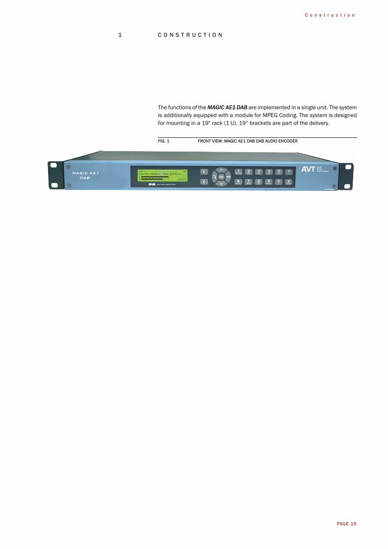
The functions of the MAGIC AE1 DAB are implemented in a single unit. The systemis additionally equipped with a module for MPEG Coding. The system is designedfor mounting in a 19" rack (1 U). 19“ brackets are part of the delivery.
FIG. 1 FRONT VIEW: MAGIC AE1 DAB DAB AUDIO ENCODER

PAGE 16
C o n s t r u c t i o n
PAGE 17
S y s t e m D e s c r i p t i o n
2 S Y S T E M D E S C R I P T I O N
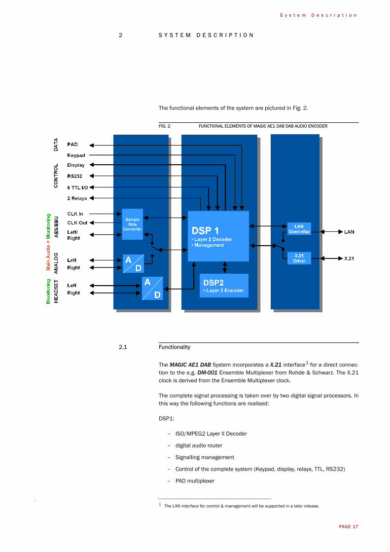
The functional elements of the system are pictured in Fig. 2.
FIG. 2 FUNCTIONAL ELEMENTS OF MAGIC AE1 DAB DAB AUDIO ENCODER
2.1 Functionality
The MAGIC AE1 DAB System incorporates a X.21 interface1 for a direct connec-tion to the e.g. DM-001 Ensemble Multiplexer from Rohde & Schwarz. The X.21clock is derived from the Ensemble Multiplexer clock.
The complete signal processing is taken over by two digital signal processors. Inthis way the following functions are realised:
DSP1:
– ISO/MPEG2 Layer II Decoder
– digital audio router
– Signalling management
– Control of the complete system (Keypad, display, relays, TTL, RS232)
– PAD multiplexer
1 The LAN interface for control & management will be supported in a later release.
PAGE 18
S y s t e m D e s c r i p t i o n
DSP2:
– ISO/MPEG2 Layer II Encoder
Via the main audio channel the high quality Stereo or Mono audio signal is in-serted analogue or digitally. If the digital AES/EBU audio interface is used, twoseparate Sample Rate Converters are available for automatic clock synchronisa-tion between network and audio source. For external clocking a clock input and aclock output are available.
The audio outputs can be used for monitoring purposes. The encoded signal islooped at every time to the MPEG decoder. The decoded audio signal is availableas analogue or digital audio output. As second audio monitoring interface a head-phone interface is available.
The configuration and operation can be primarily carried out via the front keypadand the illuminated display.
Configuration and control is especially comfortable with the MAGIC AE1 DAB Win-dows PC Software which is included in delivery and which communicates with thesystem via the RS232 interface1.
Six programmable TTL contacts can be used for external signalling. Two relays areavailable for status indication.
1 LAN control is planned.
PAGE 19
P u t t i n g t h e s y s t e m i n t o o p e r a t i o n
3 P U T T I N G T H E S Y S T E M I N T O O P E R A T I O N
3.1 Mounting
With its dimensions (W × H × D) of 431 mm × 44,5 mm (1 U) × 250 mm theMAGIC AE1 DAB system can be used either as desktop device or mounted in 19inch racks. Corresponding 19“ mounting brackets are included in delivery.
When mounting the unit please keep in mind that the bending radius of the cablesis always greater than the minimum allowed value.
When the MAGIC AE1 DAB audio encoder is installed, please make sure thatthere is sufficient ventilation: It is recommended to keep a spacing of ca. 3 cmfrom the openings. In general, the ambient temperature of the system should bewithin the range of +5°C and +45°C. These thresholds are especially to observeif the system is inserted in a rack. The system works without ventilation.
During operation air humidity must range between 5% and 85%.
3.2 Connection to the mains voltage
The system can be operated with mains voltages in the range from 90 V to 253 V.The frequency can vary from 45 Hz to 65 Hz. The maximum power consumptionis 15W (typically 12W).
After plugging the mains connector and switching on the system boots within afew seconds. In standby mode the MAGIC AE1 DAB logo is shown on the display.
3.3 Earthing of the system
For EMC reasons an earthing via the earthing screw of the system is recom-mended.
TIP The system temperature can be indicated on the display (Menu Status informa-tion (see CHAPTER A1.4, Page 63))
ATTENTION Incorrect ambient temperature and humidity can cause functional deficienciesOperation outside the threshold values indicated above leads to a loss of war-ranty claim.
ATTENTION EarthingA lacking earthing can cause functional deficiencies within the unit.
!
!
PAGE 20
P u t t i n g t h e s y s t e m i n t o o p e r a t i o n
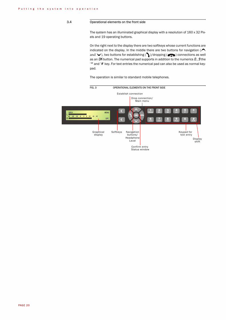
3.4 Operational elements on the front side
The system has an illuminated graphical display with a resolution of 160 x 32 Pix-els and 19 operating buttons.
On the right next to the display there are two softkeys whose current functions areindicated on the display. In the middle there are two buttons for navigation (and ), two buttons for establishing ( )/dropping ( ) connections as wellas an OK button. The numerical pad supports in addition to the numerics 0...9 the’*’ and ’#’ key. For text entries the numerical pad can also be used as normal key-pad.
The operation is similar to standard mobile telephones.
FIG. 3 OPERATIONAL ELEMENTS ON THE FRONT SIDE
Softkeys Navigationbuttons/
Establish connection
Drop connection/Main menu
Keypad for text entry
Displayshift
Confirm entry
Graphicaldisplay
Status window
HeadphoneLevel
PAGE 21
P u t t i n g t h e s y s t e m i n t o o p e r a t i o n
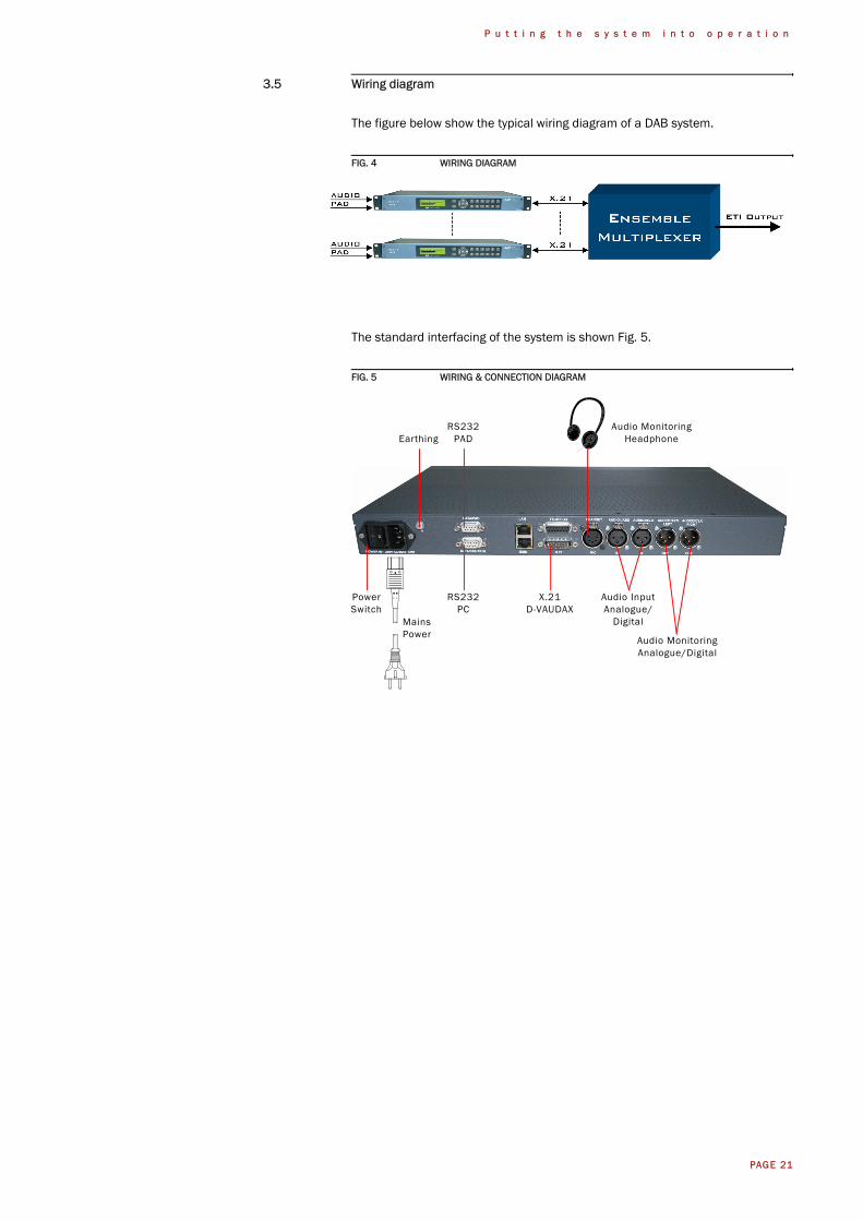
3.5 Wiring diagram
The figure below show the typical wiring diagram of a DAB system.
FIG. 4 WIRING DIAGRAM
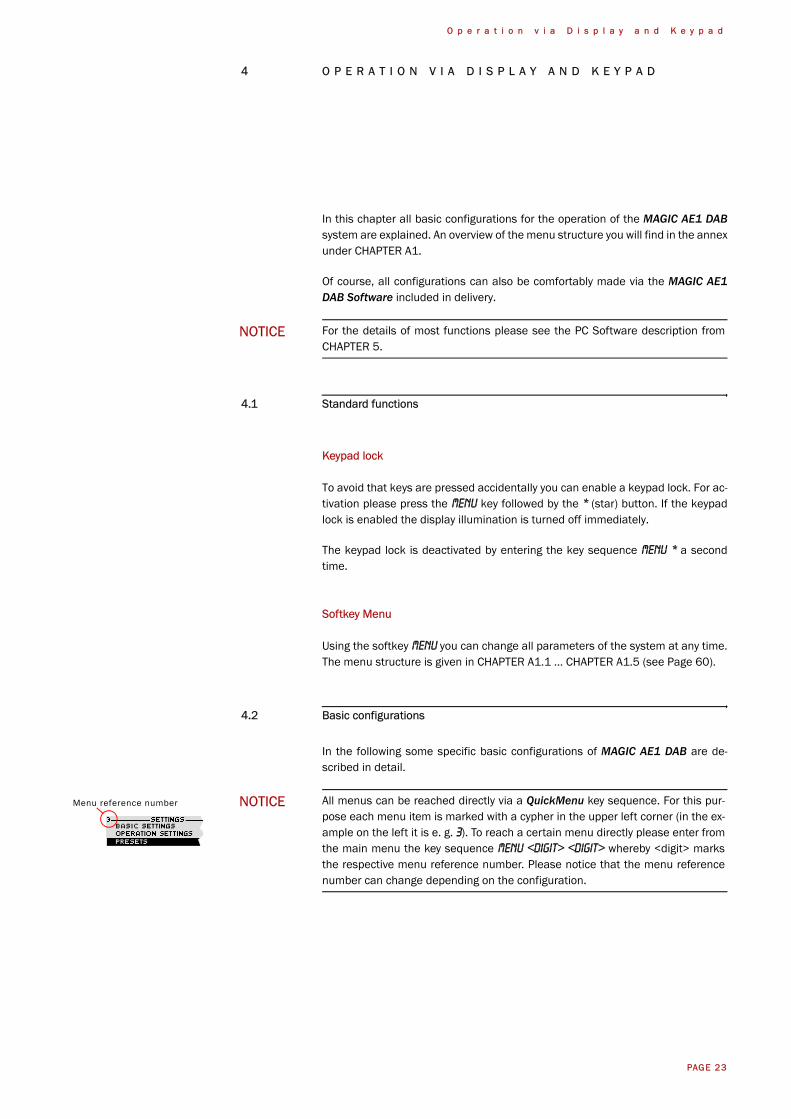
The standard interfacing of the system is shown Fig. 5.
FIG. 5 WIRING & CONNECTION DIAGRAM
Mains
RS232PC
RS232PAD
X.21D-VAUDAX
Audio InputAnalogue/
Digital
Audio MonitoringAnalogue/Digital
Audio MonitoringHeadphoneEarthing
PowerSwitch
Power

PAGE 22
P u t t i n g t h e s y s t e m i n t o o p e r a t i o n
PAGE 23
O p e r a t i o n v i a D i s p l a y a n d K e y p a d
4 O P E R A T I O N V I A D I S P L A Y A N D K E Y P A D
In this chapter all basic configurations for the operation of the MAGIC AE1 DABsystem are explained. An overview of the menu structure you will find in the annexunder CHAPTER A1.
Of course, all configurations can also be comfortably made via the MAGIC AE1DAB Software included in delivery.
4.1 Standard functions
Keypad lock
To avoid that keys are pressed accidentally you can enable a keypad lock. For ac-tivation please press the Menu key followed by the * (star) button. If the keypadlock is enabled the display illumination is turned off immediately.
The keypad lock is deactivated by entering the key sequence Menu * a secondtime.
Softkey Menu
Using the softkey Menu you can change all parameters of the system at any time.The menu structure is given in CHAPTER A1.1 ... CHAPTER A1.5 (see Page 60).
4.2 Basic configurations
In the following some specific basic configurations of MAGIC AE1 DAB are de-scribed in detail.
NOTICE For the details of most functions please see the PC Software description fromCHAPTER 5.
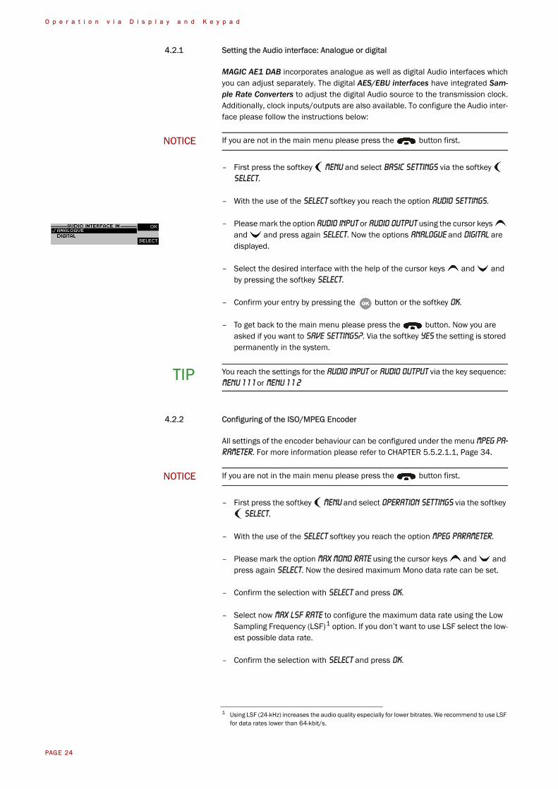
NOTICE All menus can be reached directly via a QuickMenu key sequence. For this pur-pose each menu item is marked with a cypher in the upper left corner (in the ex-ample on the left it is e. g. 3). To reach a certain menu directly please enter fromthe main menu the key sequence Menu <DIGIT> <DIGIT> whereby <digit> marksthe respective menu reference number. Please notice that the menu referencenumber can change depending on the configuration.
Menu reference number
PAGE 24
O p e r a t i o n v i a D i s p l a y a n d K e y p a d
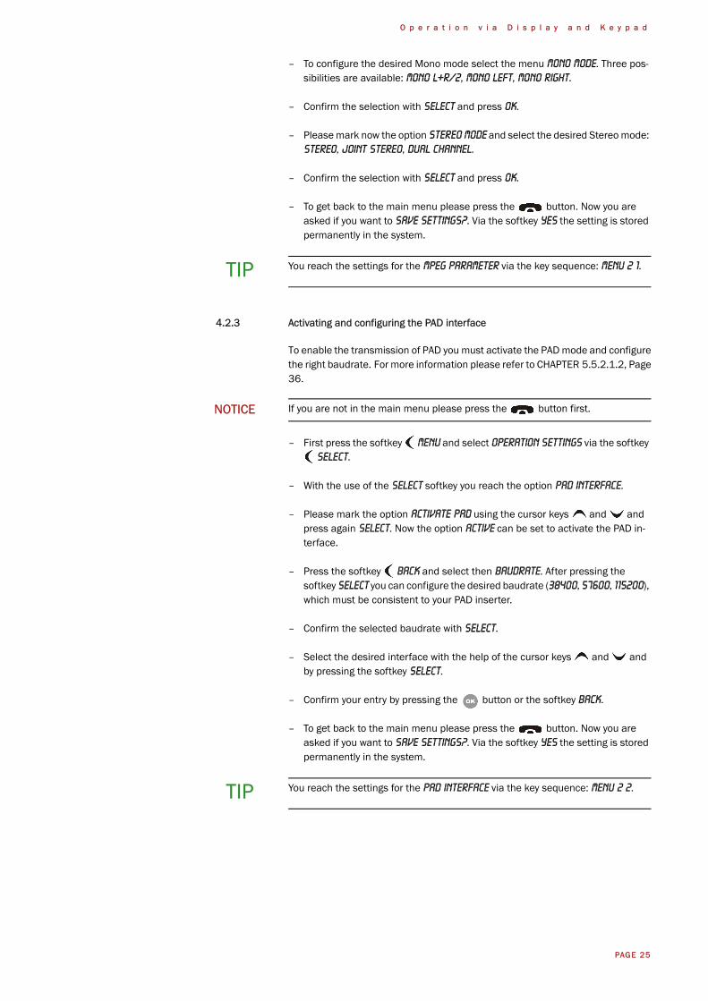
4.2.1 Setting the Audio interface: Analogue or digital
MAGIC AE1 DAB incorporates analogue as well as digital Audio interfaces whichyou can adjust separately. The digital AES/EBU interfaces have integrated Sam-ple Rate Converters to adjust the digital Audio source to the transmission clock.Additionally, clock inputs/outputs are also available. To configure the Audio inter-face please follow the instructions below:
– First press the softkey Menu and select Basic Settings via the softkey Select.
– With the use of the Select softkey you reach the option Audio Settings.
– Please mark the option Audio input or Audio output using the cursor keys and and press again Select. Now the options Analogue and Digital are displayed.
– Select the desired interface with the help of the cursor keys and and by pressing the softkey Select.
– Confirm your entry by pressing the button or the softkey Ok.
– To get back to the main menu please press the button. Now you are asked if you want to Save settings?. Via the softkey Yes the setting is stored permanently in the system.
4.2.2 Configuring of the ISO/MPEG Encoder
All settings of the encoder behaviour can be configured under the menu MPEG Pa-rameter. For more information please refer to CHAPTER 5.5.2.1.1, Page 34.
– First press the softkey Menu and select Operation Settings via the softkey Select.
– With the use of the Select softkey you reach the option MPEG Parameter.
– Please mark the option Max Mono Rate using the cursor keys and and press again Select. Now the desired maximum Mono data rate can be set.
– Confirm the selection with Select and press Ok.
– Select now Max LSF Rate to configure the maximum data rate using the Low Sampling Frequency (LSF)1 option. If you don’t want to use LSF select the low-est possible data rate.
– Confirm the selection with Select and press Ok.
NOTICE If you are not in the main menu please press the button first.
TIP You reach the settings for the Audio input or Audio output via the key sequence:Menu 1 1 1 or Menu 1 1 2
NOTICE If you are not in the main menu please press the button first.
1 Using LSF (24-kHz) increases the audio quality especially for lower bitrates. We recommend to use LSF for data rates lower than 64-kbit/s.
PAGE 25
O p e r a t i o n v i a D i s p l a y a n d K e y p a d
– To configure the desired Mono mode select the menu Mono Mode. Three pos-sibilities are available: Mono L+R/2, Mono Left, Mono Right.
– Confirm the selection with Select and press Ok.
– Please mark now the option Stereo Mode and select the desired Stereo mode: Stereo, Joint Stereo, Dual Channel.
– Confirm the selection with Select and press Ok.
– To get back to the main menu please press the button. Now you are asked if you want to Save settings?. Via the softkey Yes the setting is stored permanently in the system.
4.2.3 Activating and configuring the PAD interface
To enable the transmission of PAD you must activate the PAD mode and configurethe right baudrate. For more information please refer to CHAPTER 5.5.2.1.2, Page36.
– First press the softkey Menu and select Operation Settings via the softkey Select.
– With the use of the Select softkey you reach the option PAD Interface.
– Please mark the option Activate PAD using the cursor keys and and press again Select. Now the option Active can be set to activate the PAD in-terface.
– Press the softkey Back and select then Baudrate. After pressing the softkey Select you can configure the desired baudrate (38400, 57600, 115200), which must be consistent to your PAD inserter.
– Confirm the selected baudrate with Select.
– Select the desired interface with the help of the cursor keys and and by pressing the softkey Select.
– Confirm your entry by pressing the button or the softkey Back.
– To get back to the main menu please press the button. Now you are asked if you want to Save settings?. Via the softkey Yes the setting is stored permanently in the system.
TIP You reach the settings for the MPEG Parameter via the key sequence: Menu 2 1.
NOTICE If you are not in the main menu please press the button first.
TIP You reach the settings for the PAD Interface via the key sequence: Menu 2 2.
PAGE 26
O p e r a t i o n v i a D i s p l a y a n d K e y p a d
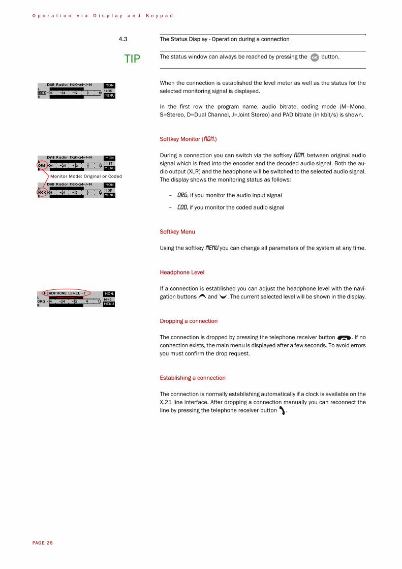
4.3 The Status Display - Operation during a connection
When the connection is established the level meter as well as the status for theselected monitoring signal is displayed.
In the first row the program name, audio bitrate, coding mode (M=Mono,S=Stereo, D=Dual Channel, J=Joint Stereo) and PAD bitrate (in kbit/s) is shown.
Softkey Monitor (Mon.)
During a connection you can switch via the softkey Mon. between original audiosignal which is feed into the encoder and the decoded audio signal. Both the au-dio output (XLR) and the headphone will be switched to the selected audio signal.The display shows the monitoring status as follows:
– Org, if you monitor the audio input signal
– Cod, if you monitor the coded audio signal
Softkey Menu
Using the softkey Menu you can change all parameters of the system at any time.
Headphone Level
If a connection is established you can adjust the headphone level with the navi-gation buttons and . The current selected level will be shown in the display.
Dropping a connection
The connection is dropped by pressing the telephone receiver button . If noconnection exists, the main menu is displayed after a few seconds. To avoid errorsyou must confirm the drop request.
Establishing a connection
The connection is normally establishing automatically if a clock is available on theX.21 line interface. After dropping a connection manually you can reconnect theline by pressing the telephone receiver button .
TIP The status window can always be reached by pressing the button.
Monitor Mode: Original or Coded
PAGE 27
O p e r a t i o n v i a D i s p l a y a n d K e y p a d
4.4 Working with Presets
The MAGIC AE1 DAB differentiates between Basic Settings and Operation Set-tings.
Basic Settings are settings that do not change during normal operation like e.g.display contrast, date/time etc. These parameters cannot be saved as presetsince a configuration is usually only required when the system is put into opera-tion.
Operation Settings need to be reconfigured depending on the application. To eas-ily recall recurring configurations you can store up to 10 presets in the system.
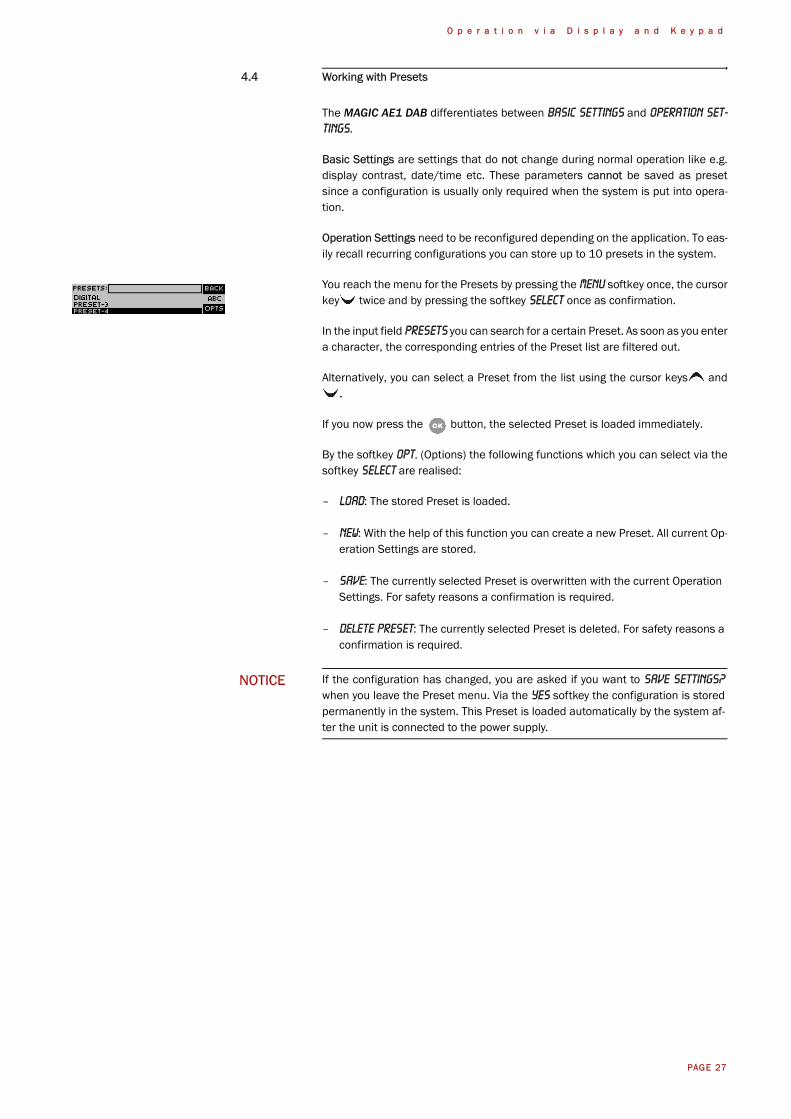
You reach the menu for the Presets by pressing the Menu softkey once, the cursorkey twice and by pressing the softkey Select once as confirmation.
In the input field Presets you can search for a certain Preset. As soon as you entera character, the corresponding entries of the Preset list are filtered out.
Alternatively, you can select a Preset from the list using the cursor keys and.
If you now press the button, the selected Preset is loaded immediately.
By the softkey Opt. (Options) the following functions which you can select via thesoftkey Select are realised:
– Load: The stored Preset is loaded.
– New: With the help of this function you can create a new Preset. All current Op-eration Settings are stored.
– Save: The currently selected Preset is overwritten with the current Operation Settings. For safety reasons a confirmation is required.
– Delete Preset: The currently selected Preset is deleted. For safety reasons a confirmation is required.
NOTICE If the configuration has changed, you are asked if you want to Save settings?when you leave the Preset menu. Via the Yes softkey the configuration is storedpermanently in the system. This Preset is loaded automatically by the system af-ter the unit is connected to the power supply.

PAGE 28
O p e r a t i o n v i a D i s p l a y a n d K e y p a d
PAGE 29
W i n d o w s P C S o f t w a r e
5 W I N D O W S P C S O F T W A R E
The configuration of the system is particularly comfortable via the Windows PCSoftware included in delivery.
5.1 Hardware requirements
The PC must meet the following minimum requirements:
– IBM PC AT, IBM PS/2 or 100% compatible
– Pentium Prozessor (> 1 GHz) recommended
– Windows 2000/XP
– ca. 600 kByte available RAM
– 5 MB available hard disk space
– Screen resolution with 800 x 600 Pixels
– at least one available serial interface RS-232
– Microsoft, IBM PS/2 or 100% software compatible mouse
5.2 Installing the Windows PC Software
Please insert the CD included in delivery in your CD-ROM drive. The software au-tomatically starts your Internet browser. Possible safety warnings can be ignoredfor the moment. Please press under Install Software the MAGIC AE1 DAB but-ton. Subsequently, the setup program is executed.
Alternatively, you can install the software directly from the CD. You will find the in-stallation file setup.exe in the folder Software\MAGIC AE1 DAB on the CD.
Please follow the instructions of the installation routine.
After the installation the software can be started by clicking on the MAGIC AE1DAB icon.
Please connect your PC via a serial 1:1 cable (only Pin 2 and Pin 3 are used, Pin5=ground) with the system.
The standard COM-Port settings are: 38400 Baud
Operation via Windows PC software
In the following chapters all functions of the PC software are described in detail.
PAGE 30
W i n d o w s P C S o f t w a r e
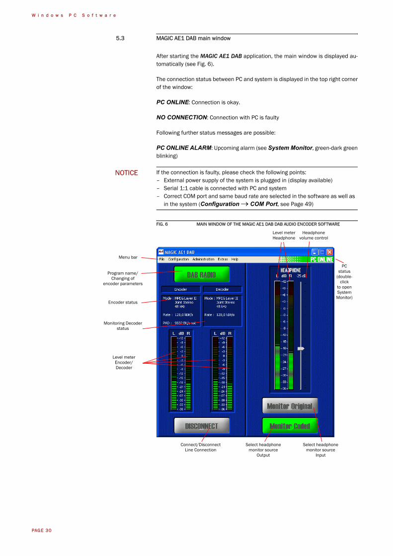
5.3 MAGIC AE1 DAB main window
After starting the MAGIC AE1 DAB application, the main window is displayed au-tomatically (see Fig. 6).
The connection status between PC and system is displayed in the top right cornerof the window:
PC ONLINE: Connection is okay.
NO CONNECTION: Connection with PC is faulty
Following further status messages are possible:
PC ONLINE ALARM: Upcoming alarm (see System Monitor, green-dark greenblinking)
FIG. 6 MAIN WINDOW OF THE MAGIC AE1 DAB DAB AUDIO ENCODER SOFTWARE
NOTICE If the connection is faulty, please check the following points:– External power supply of the system is plugged in (display available)– Serial 1:1 cable is connected with PC and system– Correct COM port and same baud rate are selected in the software as well as
in the system (Configuration → COM Port, see Page 49)
Menu bar
Program name/Changing of
encoder parameters
Encoder status
Monitoring Decoderstatus
Select headphonemonitor source
Output
Select headphonemonitor source
Input
Level meterHeadphone
Headphonevolume control
PCstatus
(double-click
to openSystemMonitor)
Level meterEncoder/Decoder
Connect/DisconnectLine Connection
PAGE 31
W i n d o w s P C S o f t w a r e
5.3.1 Operating elements
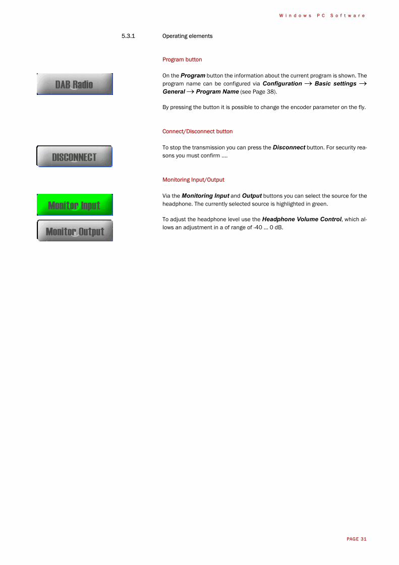
Program button
On the Program button the information about the current program is shown. Theprogram name can be configured via Configuration → Basic settings →General → Program Name (see Page 38).
By pressing the button it is possible to change the encoder parameter on the fly.
Connect/Disconnect button
To stop the transmission you can press the Disconnect button. For security rea-sons you must confirm ....
Monitoring Input/Output
Via the Monitoring Input and Output buttons you can select the source for theheadphone. The currently selected source is highlighted in green.
To adjust the headphone level use the Headphone Volume Control, which al-lows an adjustment in a of range of -40 ... 0 dB.
PAGE 32
W i n d o w s P C S o f t w a r e
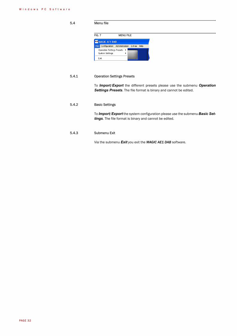
5.4 Menu file
FIG. 7 MENU FILE
5.4.1 Operation Settings Presets
To Import/Export the different presets please use the submenu OperationSettings Presets. The file format is binary and cannot be edited.
5.4.2 Basic Settings
To Import/Export the system configuration please use the submenu Basic Set-tings. The file format is binary and cannot be edited.
5.4.3 Submenu Exit
Via the submenu Exit you exit the MAGIC AE1 DAB software.
PAGE 33
W i n d o w s P C S o f t w a r e
5.5 Menu Configuration
FIG. 8 MENU CONFIGURATION
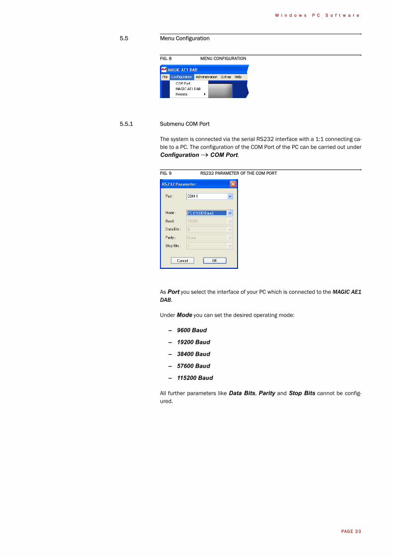
5.5.1 Submenu COM Port
The system is connected via the serial RS232 interface with a 1:1 connecting ca-ble to a PC. The configuration of the COM Port of the PC can be carried out underConfiguration → COM Port.
FIG. 9 RS232 PARAMETER OF THE COM PORT
As Port you select the interface of your PC which is connected to the MAGIC AE1DAB.
Under Mode you can set the desired operating mode:
– 9600 Baud
– 19200 Baud
– 38400 Baud
– 57600 Baud
– 115200 Baud
All further parameters like Data Bits, Parity and Stop Bits cannot be config-ured.
PAGE 34
W i n d o w s P C S o f t w a r e
5.5.2 Submenu MAGIC AE1 DAB
Via the submenu MAGIC AE1 DAB the system can be configured comfortably.It is distinguished between Basic Settings, which do not have to be changedduring the operation and the actual Configuration for the current application. Incontrast to a configuration, the basic settings cannot be saved as Preset (seeCHAPTER 5.5.3).
5.5.2.1 Operation Settings
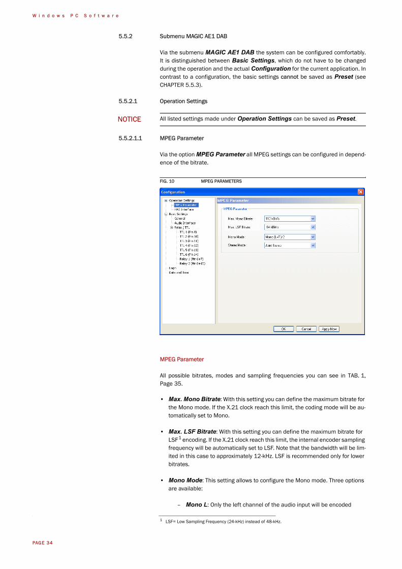
5.5.2.1.1 MPEG Parameter
Via the option MPEG Parameter all MPEG settings can be configured in depend-ence of the bitrate.
FIG. 10 MPEG PARAMETERS
MPEG Parameter
All possible bitrates, modes and sampling frequencies you can see in TAB. 1,Page 35.
• Max. Mono Bitrate: With this setting you can define the maximum bitrate for the Mono mode. If the X.21 clock reach this limit, the coding mode will be au-tomatically set to Mono.
• Max. LSF Bitrate: With this setting you can define the maximum bitrate for LSF1 encoding. If the X.21 clock reach this limit, the internal encoder sampling frequency will be automatically set to LSF. Note that the bandwidth will be lim-ited in this case to approximately 12-kHz. LSF is recommended only for lower bitrates.
• Mono Mode: This setting allows to configure the Mono mode. Three options are available:
– Mono L: Only the left channel of the audio input will be encoded
NOTICE All listed settings made under Operation Settings can be saved as Preset.
1 LSF= Low Sampling Frequency (24-kHz) instead of 48-kHz.
PAGE 35
W i n d o w s P C S o f t w a r e
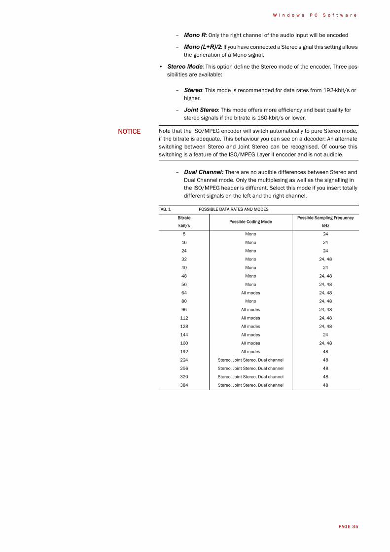
– Mono R: Only the right channel of the audio input will be encoded
– Mono (L+R)/2: If you have connected a Stereo signal this setting allows the generation of a Mono signal.
• Stereo Mode: This option define the Stereo mode of the encoder. Three pos-sibilities are available:
– Stereo: This mode is recommended for data rates from 192-kbit/s or higher.
– Joint Stereo: This mode offers more efficiency and best quality for stereo signals if the bitrate is 160-kbit/s or lower.
– Dual Channel: There are no audible differences between Stereo and Dual Channel mode. Only the multiplexing as well as the signalling in the ISO/MPEG header is different. Select this mode if you insert totally different signals on the left and the right channel.
NOTICE Note that the ISO/MPEG encoder will switch automatically to pure Stereo mode,if the bitrate is adequate. This behaviour you can see on a decoder: An alternateswitching between Stereo and Joint Stereo can be recognised. Of course thisswitching is a feature of the ISO/MPEG Layer II encoder and is not audible.
TAB. 1 POSSIBLE DATA RATES AND MODES
Bitrate
kbit/sPossible Coding Mode
Possible Sampling Frequency
kHz
8 Mono 24
16 Mono 24
24 Mono 24
32 Mono 24, 48
40 Mono 24
48 Mono 24, 48
56 Mono 24, 48
64 All modes 24, 48
80 Mono 24, 48
96 All modes 24, 48
112 All modes 24, 48
128 All modes 24, 48
144 All modes 24
160 All modes 24, 48
192 All modes 48
224 Stereo, Joint Stereo, Dual channel 48
256 Stereo, Joint Stereo, Dual channel 48
320 Stereo, Joint Stereo, Dual channel 48
384 Stereo, Joint Stereo, Dual channel 48
PAGE 36
W i n d o w s P C S o f t w a r e
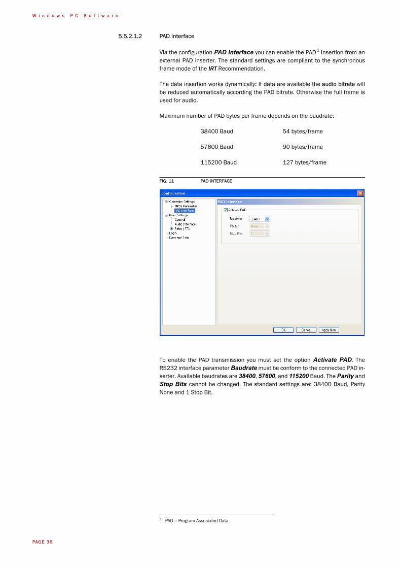
5.5.2.1.2 PAD Interface
Via the configuration PAD Interface you can enable the PAD1 Insertion from anexternal PAD inserter. The standard settings are compliant to the synchronousframe mode of the IRT Recommendation.
The data insertion works dynamically: If data are available the audio bitrate willbe reduced automatically according the PAD bitrate. Otherwise the full frame isused for audio.
Maximum number of PAD bytes per frame depends on the baudrate:
38400 Baud 54 bytes/frame
57600 Baud 90 bytes/frame
115200 Baud 127 bytes/frame
FIG. 11 PAD INTERFACE
To enable the PAD transmission you must set the option Activate PAD. TheRS232 interface parameter Baudrate must be conform to the connected PAD in-serter. Available baudrates are 38400, 57600, and 115200 Baud. The Parity andStop Bits cannot be changed. The standard settings are: 38400 Baud, ParityNone and 1 Stop Bit.
1 PAD = Program Associated Data
PAGE 37
W i n d o w s P C S o f t w a r e
5.5.2.2 Basic Settings
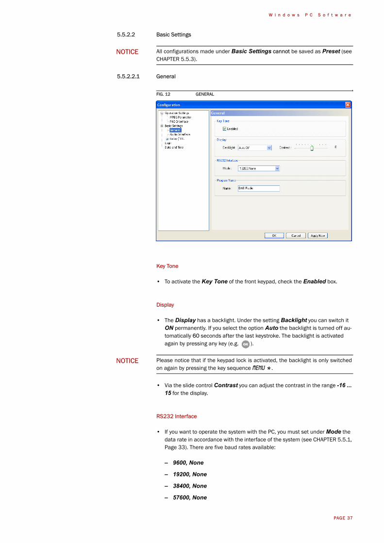
5.5.2.2.1 General
FIG. 12 GENERAL
Key Tone
• To activate the Key Tone of the front keypad, check the Enabled box.
Display
• The Display has a backlight. Under the setting Backlight you can switch it ON permanently. If you select the option Auto the backlight is turned off au-tomatically 60 seconds after the last keystroke. The backlight is activated again by pressing any key (e.g. ).
• Via the slide control Contrast you can adjust the contrast in the range -16 ... 15 for the display.
RS232 Interface
• If you want to operate the system with the PC, you must set under Mode the data rate in accordance with the interface of the system (see CHAPTER 5.5.1, Page 33). There are five baud rates available:
– 9600, None
– 19200, None
– 38400, None
– 57600, None
NOTICE All configurations made under Basic Settings cannot be saved as Preset (seeCHAPTER 5.5.3).
NOTICE Please notice that if the keypad lock is activated, the backlight is only switchedon again by pressing the key sequence Menu * .

PAGE 38
W i n d o w s P C S o f t w a r e
– 115200, None
Program Name
• The entered Name of the program will be shown on the Program button (see Page 31) in the PC software main window as well as in the status line of the system display.
PAGE 39
W i n d o w s P C S o f t w a r e
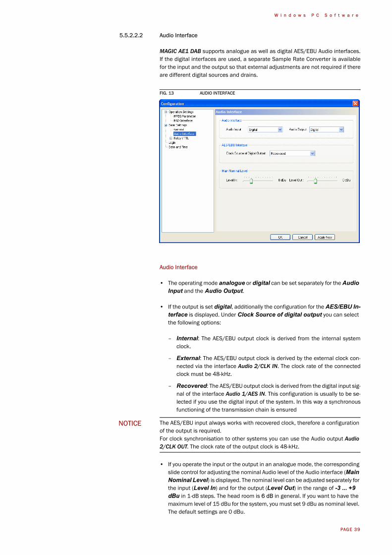
5.5.2.2.2 Audio Interface
MAGIC AE1 DAB supports analogue as well as digital AES/EBU Audio interfaces.If the digital interfaces are used, a separate Sample Rate Converter is availablefor the input and the output so that external adjustments are not required if thereare different digital sources and drains.
FIG. 13 AUDIO INTERFACE
Audio Interface
• The operating mode analogue or digital can be set separately for the Audio Input and the Audio Output.
• If the output is set digital, additionally the configuration for the AES/EBU In-terface is displayed. Under Clock Source of digital output you can select the following options:
– Internal: The AES/EBU output clock is derived from the internal systemclock.
– External: The AES/EBU output clock is derived by the external clock con-nected via the interface Audio 2/CLK IN. The clock rate of the connectedclock must be 48-kHz.
– Recovered: The AES/EBU output clock is derived from the digital input sig-nal of the interface Audio 1/AES IN. This configuration is usually to be se-lected if you use the digital input of the system. In this way a synchronousfunctioning of the transmission chain is ensured
• If you operate the input or the output in an analogue mode, the corresponding slide control for adjusting the nominal Audio level of the Audio interface (Main Nominal Level) is displayed. The nominal level can be adjusted separately for the input (Level In) and for the output (Level Out) in the range of -3 ... +9 dBu in 1-dB steps. The head room is 6 dB in general. If you want to have the maximum level of 15 dBu for the system, you must set 9 dBu as nominal level. The default settings are 0 dBu.
NOTICE The AES/EBU input always works with recovered clock, therefore a configurationof the output is required.For clock synchronisation to other systems you can use the Audio output Audio2/CLK OUT. The clock rate of the output clock is 48-kHz.
PAGE 40
W i n d o w s P C S o f t w a r e
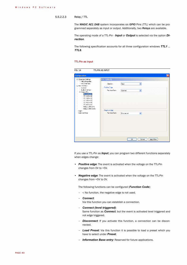
5.5.2.2.3 Relay / TTL
The MAGIC AE1 DAB system incorporates six GPIO Pins (TTL) which can be pro-grammed separately as input or output. Additionally, two Relays are available.
The operating mode of a TTL-Pin - Input or Output is selected via the option Di-rection.
The following specification accounts for all three configuration windows TTL1 ...TTL6.
TTL-Pin as input
FIG. 14 TTL-PIN AS INPUT
If you use a TTL-Pin as Input, you can program two different functions separatelywhen edges change:
• Positive edge: The event is activated when the voltage on the TTL-Pin changes from 0V to +5V.
• Negative edge: The event is activated when the voltage on the TTL-Pin changes from +5V to 0V.
The following functions can be configured (Function Code):
– -: No function, the negative edge is not used.
– Connect:Via this function you can establish a connection.
– Connect (level triggered):Same function as Connect, but the event is activated level triggered andnot edge triggered.
– Disconnect: If you activate this function, a connection can be discon-nected.
– Load Preset: Via this function it is possible to load a preset which youhave to select under Preset.
– Information Base entry: Reserved for future applications.
PAGE 41
W i n d o w s P C S o f t w a r e
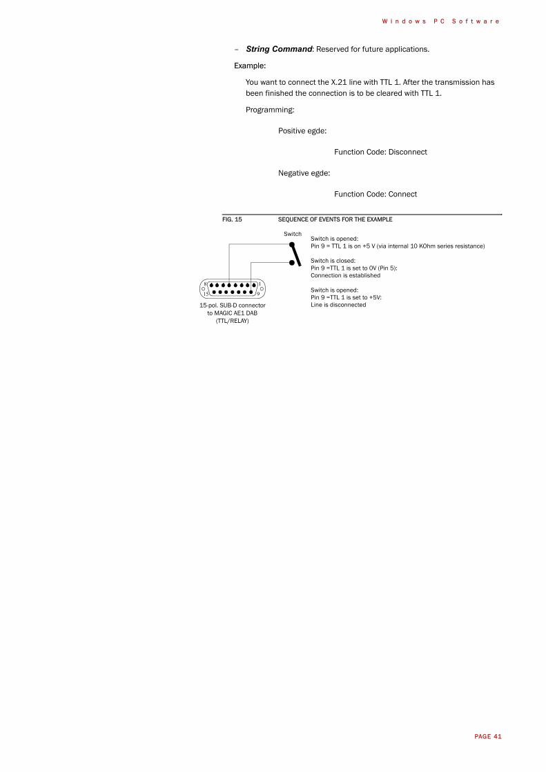
– String Command: Reserved for future applications.
Example:
You want to connect the X.21 line with TTL 1. After the transmission has been finished the connection is to be cleared with TTL 1.
Programming:
Positive egde:
Function Code: Disconnect
Negative egde:
Function Code: Connect
FIG. 15 SEQUENCE OF EVENTS FOR THE EXAMPLE
15-pol. SUB-D connectorto MAGIC AE1 DAB
(TTL/RELAY)
Switch is opened:Pin 9 = TTL 1 is on +5 V (via internal 10 KOhm series resistance)
Switch is closed:Pin 9 =TTL 1 is set to 0V (Pin 5):Connection is established
Switch is opened:Pin 9 =TTL 1 is set to +5V:Line is disconnected
Switch
18
915
PAGE 42
W i n d o w s P C S o f t w a r e
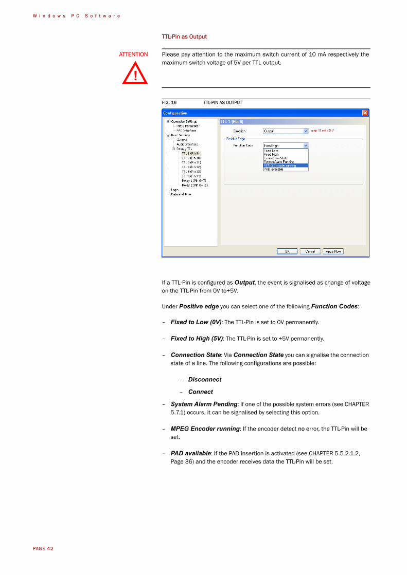
TTL-Pin as Output
FIG. 16 TTL-PIN AS OUTPUT
If a TTL-Pin is configured as Output, the event is signalised as change of voltageon the TTL-Pin from 0V to+5V.
Under Positive edge you can select one of the following Function Codes:
– Fixed to Low (0V): The TTL-Pin is set to 0V permanently.
– Fixed to High (5V): The TTL-Pin is set to +5V permanently.
– Connection State: Via Connection State you can signalise the connection state of a line. The following configurations are possible:
– Disconnect
– Connect
– System Alarm Pending: If one of the possible system errors (see CHAPTER 5.7.1) occurs, it can be signalised by selecting this option.
– MPEG Encoder running: If the encoder detect no error, the TTL-Pin will be set.
– PAD available: If the PAD insertion is activated (see CHAPTER 5.5.2.1.2, Page 36) and the encoder receives data the TTL-Pin will be set.
ATTENTION Please pay attention to the maximum switch current of 10 mA respectively themaximum switch voltage of 5V per TTL output.
!
PAGE 43
W i n d o w s P C S o f t w a r e
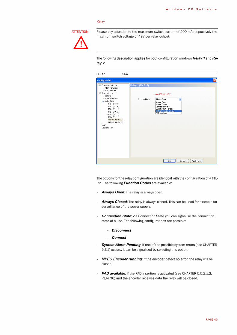
Relay
The following description applies for both configuration windows Relay 1 and Re-lay 2.
FIG. 17 RELAY
The options for the relay configuration are identical with the configuration of a TTL-Pin. The following Function Codes are available:
– Always Open: The relay is always open.
– Always Closed: The relay is always closed. This can be used for example for surveillance of the power supply.
– Connection State: Via Connection State you can signalise the connection state of a line. The following configurations are possible:
– Disconnect
– Connect
– System Alarm Pending: If one of the possible system errors (see CHAPTER 5.7.1) occurs, it can be signalised by selecting this option.
– MPEG Encoder running: If the encoder detect no error, the relay will be closed.
– PAD available: If the PAD insertion is activated (see CHAPTER 5.5.2.1.2, Page 36) and the encoder receives data the relay will be closed.
ATTENTION Please pay attention to the maximum switch current of 200 mA respectively themaximum switch voltage of 48V per relay output.
!
PAGE 44
W i n d o w s P C S o f t w a r e
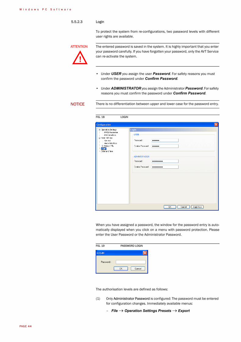
5.5.2.3 Login
To protect the system from re-configurations, two password levels with differentuser rights are available.
• Under USER you assign the user Password. For safety reasons you must confirm the password under Confirm Password.
• Under ADMINISTRATOR you assign the Administrator Password. For safety reasons you must confirm the password under Confirm Password.
FIG. 18 LOGIN
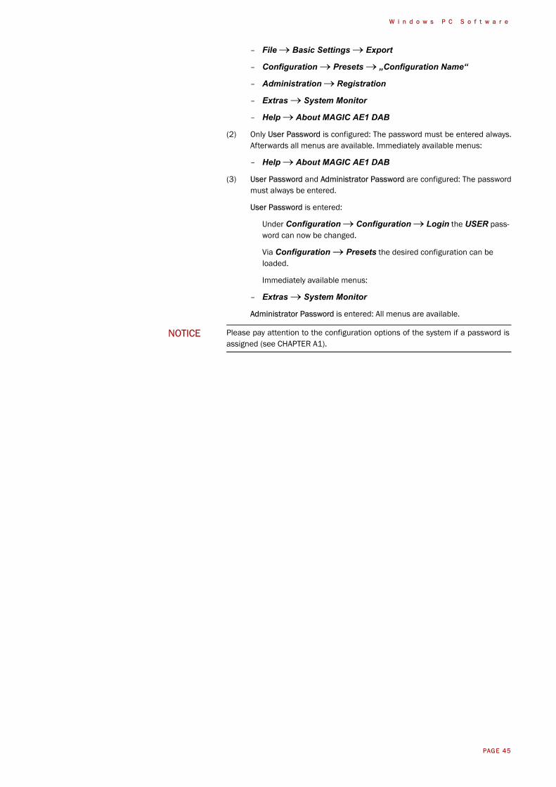
When you have assigned a password, the window for the password entry is auto-matically displayed when you click on a menu with password protection. Pleaseenter the User Password or the Administrator Password.
FIG. 19 PASSWORD LOGIN
The authorisation levels are defined as follows:
(1) Only Administrator Password is configured: The password must be entered for configuration changes. Immediately available menus:
– File → Operation Settings Presets → Export
ATTENTION The entered password is saved in the system. It is highly important that you enteryour password carefully. If you have forgotten your password, only the AVT Servicecan re-activate the system.
NOTICE There is no differentiation between upper and lower case for the password entry.
!
PAGE 45
W i n d o w s P C S o f t w a r e
– File → Basic Settings → Export
– Configuration → Presets → „Configuration Name“
– Administration → Registration
– Extras → System Monitor
– Help → About MAGIC AE1 DAB
(2) Only User Password is configured: The password must be entered always.Afterwards all menus are available. Immediately available menus:
– Help → About MAGIC AE1 DAB
(3) User Password and Administrator Password are configured: The passwordmust always be entered.
User Password is entered:
Under Configuration → Configuration → Login the USER pass-word can now be changed.
Via Configuration → Presets the desired configuration can be loaded.
Immediately available menus:
– Extras → System Monitor
Administrator Password is entered: All menus are available.
NOTICE Please pay attention to the configuration options of the system if a password isassigned (see CHAPTER A1).
PAGE 46
W i n d o w s P C S o f t w a r e
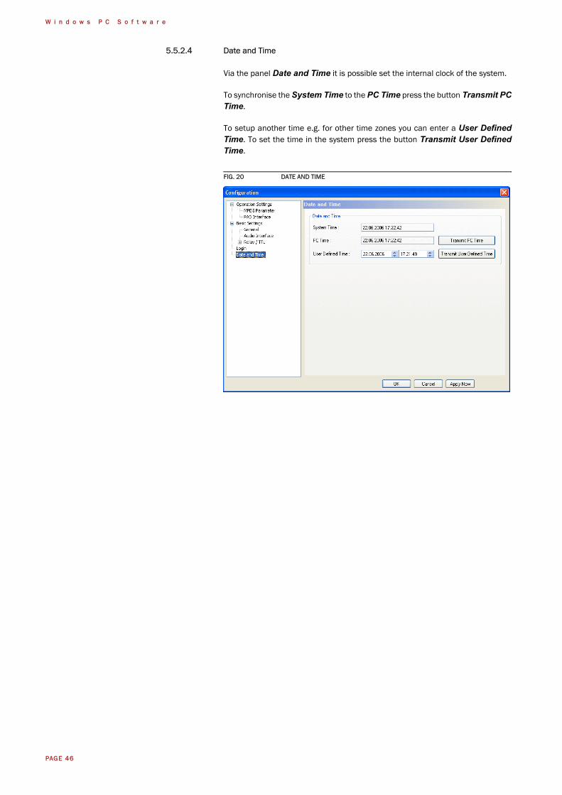
5.5.2.4 Date and Time
Via the panel Date and Time it is possible set the internal clock of the system.
To synchronise the System Time to the PC Time press the button Transmit PCTime.
To setup another time e.g. for other time zones you can enter a User DefinedTime. To set the time in the system press the button Transmit User DefinedTime.
FIG. 20 DATE AND TIME
PAGE 47
W i n d o w s P C S o f t w a r e
5.5.3 Submenu Presets
Via Presets you can load already created configurations.
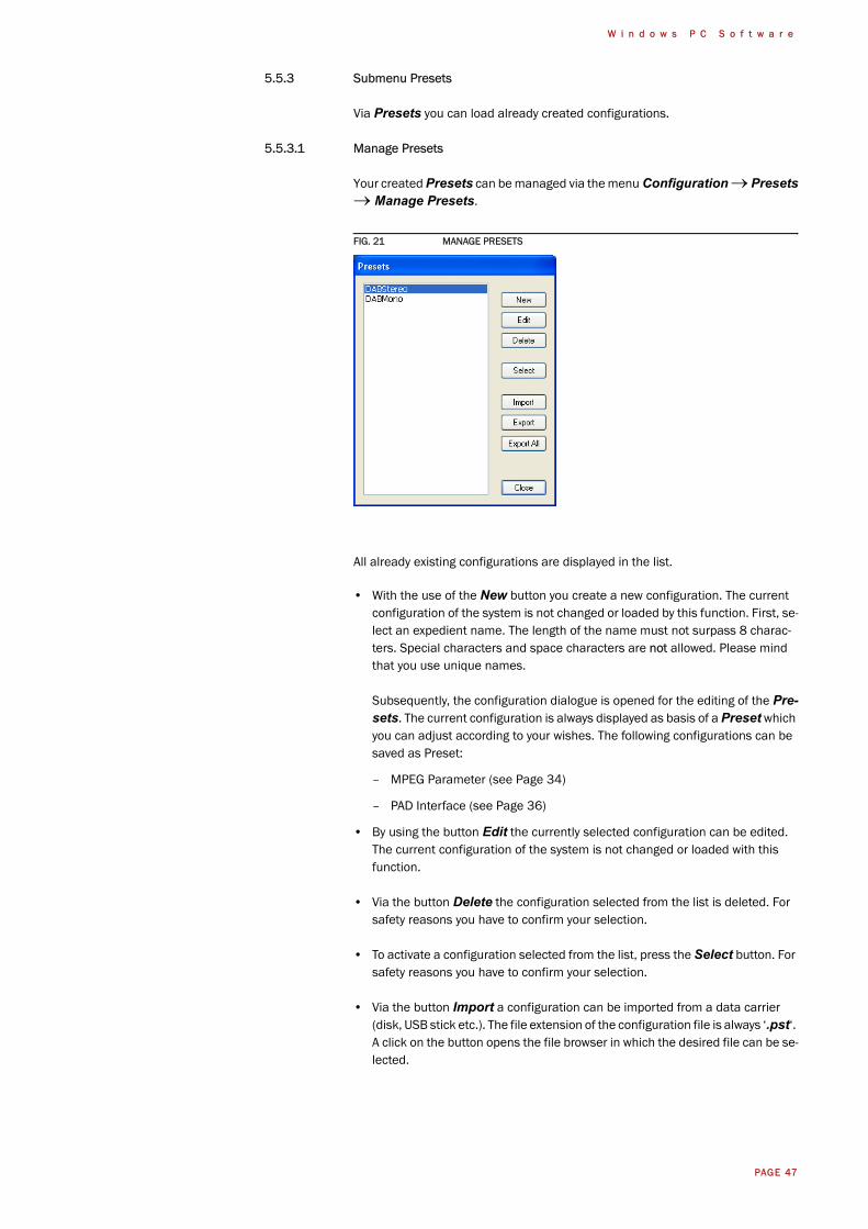
5.5.3.1 Manage Presets
Your created Presets can be managed via the menu Configuration → Presets→ Manage Presets.
FIG. 21 MANAGE PRESETS
All already existing configurations are displayed in the list.
• With the use of the New button you create a new configuration. The current configuration of the system is not changed or loaded by this function. First, se-lect an expedient name. The length of the name must not surpass 8 charac-ters. Special characters and space characters are not allowed. Please mind that you use unique names.
Subsequently, the configuration dialogue is opened for the editing of the Pre-sets. The current configuration is always displayed as basis of a Preset which you can adjust according to your wishes. The following configurations can be saved as Preset:
– MPEG Parameter (see Page 34)
– PAD Interface (see Page 36)
• By using the button Edit the currently selected configuration can be edited. The current configuration of the system is not changed or loaded with this function.
• Via the button Delete the configuration selected from the list is deleted. For safety reasons you have to confirm your selection.
• To activate a configuration selected from the list, press the Select button. For safety reasons you have to confirm your selection.
• Via the button Import a configuration can be imported from a data carrier (disk, USB stick etc.). The file extension of the configuration file is always ‘.pst‘. A click on the button opens the file browser in which the desired file can be se-lected.
PAGE 48
W i n d o w s P C S o f t w a r e
• Likewise, it is possible to export configurations to a data carrier. The button Export saves the configuration selected from the list as ‘.pst‘ file. By clicking on the button the file browser is opened and you can choose the location where the file is saved.
With Export All all configurations displayed in the list are saved in a directory of your choice. A separate data file with the file extension ’.pst‘ is generated for each configuration.
5.5.3.2 Activation of a Preset
All Presets are displayed under Configuration → Presets → „Preset Name“and can be activated with a click.
For safety reasons a confirmation is required.
TIP If you need to configure several systems in the same way, set up one system firstand export all configurations to a disk. To configure all further systems easily, im-port the configurations from the disk.
This is also possible for the Basic Settings. Via the Import/Export function un-der File (see CHAPTER 5.4) you can comfortably save all information and load onother systems.
PAGE 49
W i n d o w s P C S o f t w a r e
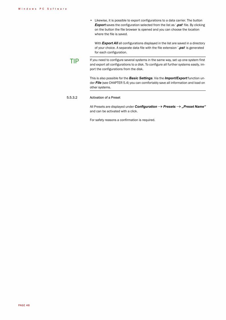
5.6 Menu Administration
FIG. 22 MENU ADMINISTRATION
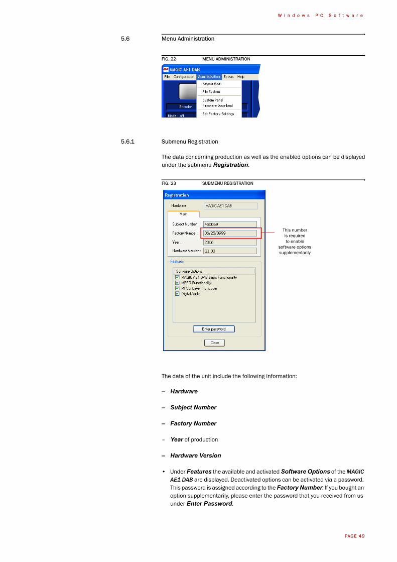
5.6.1 Submenu Registration
The data concerning production as well as the enabled options can be displayedunder the submenu Registration.
FIG. 23 SUBMENU REGISTRATION
The data of the unit include the following information:
– Hardware
– Subject Number
– Factory Number
– Year of production
– Hardware Version
• Under Features the available and activated Software Options of the MAGIC AE1 DAB are displayed. Deactivated options can be activated via a password. This password is assigned according to the Factory Number. If you bought an option supplementarily, please enter the password that you received from us under Enter Password.
This numberis requiredto enable
software optionssupplementarily
PAGE 50
W i n d o w s P C S o f t w a r e
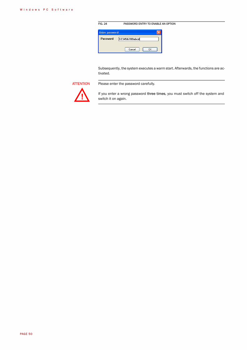
FIG. 24 PASSWORD ENTRY TO ENABLE AN OPTION
Subsequently, the system executes a warm start. Afterwards, the functions are ac-tivated.
ATTENTION Please enter the password carefully.
If you enter a wrong password three times, you must switch off the system andswitch it on again.!
PAGE 51
W i n d o w s P C S o f t w a r e
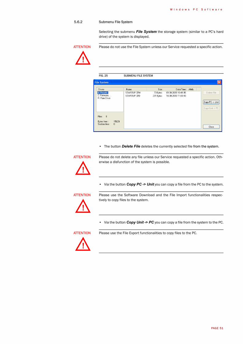
5.6.2 Submenu File System
Selecting the submenu File System the storage system (similar to a PC’s harddrive) of the system is displayed.
FIG. 25 SUBMENU FILE SYSTEM
• The button Delete File deletes the currently selected file from the system.
• Via the button Copy PC -> Unit you can copy a file from the PC to the system.
• Via the button Copy Unit -> PC you can copy a file from the system to the PC.
ATTENTION Please do not use the File System unless our Service requested a specific action.
ATTENTION Please do not delete any file unless our Service requested a specific action. Oth-erwise a disfunction of the system is possible.
ATTENTION Please use the Software Download and the File Import functionalities respec-tively to copy files to the system.
ATTENTION Please use the File Export functionalities to copy files to the PC.
!
!
!
!
PAGE 52
W i n d o w s P C S o f t w a r e
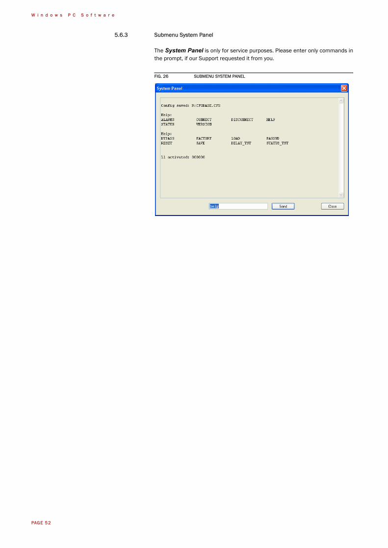
5.6.3 Submenu System Panel
The System Panel is only for service purposes. Please enter only commands inthe prompt, if our Support requested it from you.
FIG. 26 SUBMENU SYSTEM PANEL
PAGE 53
W i n d o w s P C S o f t w a r e
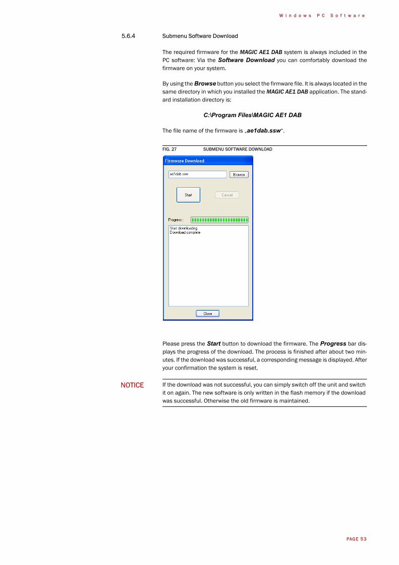
5.6.4 Submenu Software Download
The required firmware for the MAGIC AE1 DAB system is always included in thePC software: Via the Software Download you can comfortably download thefirmware on your system.
By using the Browse button you select the firmware file. It is always located in thesame directory in which you installed the MAGIC AE1 DAB application. The stand-ard installation directory is:
C:\Program Files\MAGIC AE1 DAB
The file name of the firmware is „ae1dab.ssw“.
FIG. 27 SUBMENU SOFTWARE DOWNLOAD
Please press the Start button to download the firmware. The Progress bar dis-plays the progress of the download. The process is finished after about two min-utes. If the download was successful, a corresponding message is displayed. Afteryour confirmation the system is reset.
NOTICE If the download was not successful, you can simply switch off the unit and switchit on again. The new software is only written in the flash memory if the downloadwas successful. Otherwise the old firmware is maintained.

PAGE 54
W i n d o w s P C S o f t w a r e
5.6.5 Submenu Set Factory Settings
By using the submenu Set Factory Settings the system can be reset to the ini-tial state.
For safety reasons you have to confirm your selection.
PAGE 55
W i n d o w s P C S o f t w a r e
5.7 Menu Extras
FIG. 28 MENU EXTRAS
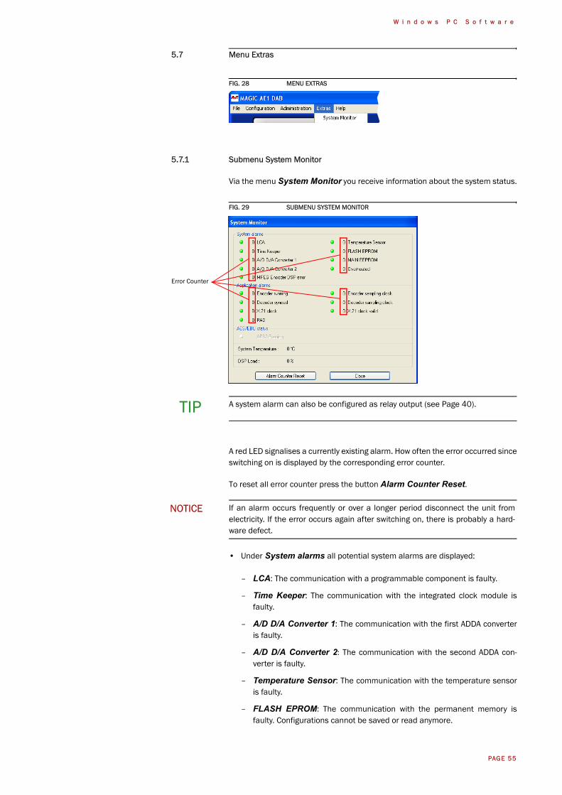
5.7.1 Submenu System Monitor
Via the menu System Monitor you receive information about the system status.
FIG. 29 SUBMENU SYSTEM MONITOR
A red LED signalises a currently existing alarm. How often the error occurred sinceswitching on is displayed by the corresponding error counter.
To reset all error counter press the button Alarm Counter Reset.
• Under System alarms all potential system alarms are displayed:
– LCA: The communication with a programmable component is faulty.
– Time Keeper: The communication with the integrated clock module isfaulty.
– A/D D/A Converter 1: The communication with the first ADDA converteris faulty.
– A/D D/A Converter 2: The communication with the second ADDA con-verter is faulty.
– Temperature Sensor: The communication with the temperature sensoris faulty.
– FLASH EPROM: The communication with the permanent memory isfaulty. Configurations cannot be saved or read anymore.
TIP A system alarm can also be configured as relay output (see Page 40).
NOTICE If an alarm occurs frequently or over a longer period disconnect the unit fromelectricity. If the error occurs again after switching on, there is probably a hard-ware defect.
Error Counter
PAGE 56
W i n d o w s P C S o f t w a r e
– MAIN EEPROM: The communication with the permanent memory isfaulty. Configurations cannot be saved or read anymore.
– Overheated: The system sets this alarm if the system temperature ishigher than 57°C. Disconnect the unit from electricity or cool down the am-bient temperature.
– MPEG Encoder DSP error: This alarm occurs, if an error on the DSPmodule is detected.
• Under Application alarms all ISO/MPEG alarms are centralised:
– Encoder running: If the encoder is not running, this alarm will be set.
– Decoder synced: For monitoring purposes the coded signal is decoded atany time via the integrated ISO/MPEG decoder.
– X.21 clock: This alarm occurs, if the external X.21 line clock is not availa-ble.
– X.21 clock valid: This alarm occurs, if the external X.21 line clock is notlocked to one of the available bitrates (see TAB. 1, Page 35)
– PAD: If PAD is activated, but no data are available at the PAD interface, thisalarm will be set.
– Encoder sampling clock: This alarm occurs if the hardware samplingclock do not fit with the expected sampling clock of the encoder.
– Decoder sampling clock: This alarm occurs if the hardware samplingclock do not fit with the expected sampling clock of the decoder.
• The AES/EBU status shows the current status of the AES/EBU input if the digital audio input is selected (see CHAPTER 5.5.2.2.2).
The actual system temperature is displayed in °C under System Temperature.The regular system temperature ranges from 30...45°C.
Under DSP Load the load of the system is displayed. The usual load is about 55to 65%.
PAGE 57
W i n d o w s P C S o f t w a r e
5.8 Menu Help
FIG. 30 MENU HELP
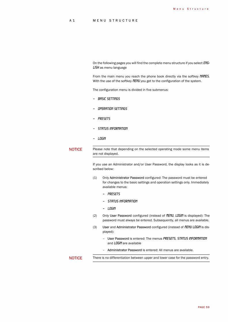
5.8.1 Submenu About MAGIC AE1 DAB
In the About MAGIC AE1 DAB dialogue you find the software versions of thePC software (PC Version) and of the systems (Firmware Version). Besides, youcan find our contact details there.
FIG. 31 SUBMENU ABOUT MAGIC AE1 DAB

PAGE 58
W i n d o w s P C S o f t w a r e
PAGE 59
M e n u S t r u c t u r e
A 1 M E N U S T R U C T U R E
On the following pages you will find the complete menu structure if you select ENG-LISH as menu language
From the main menu you reach the phone book directly via the softkey Names.With the use of the softkey Menu you get to the configuration of the system.
The configuration menu is divided in five submenus:
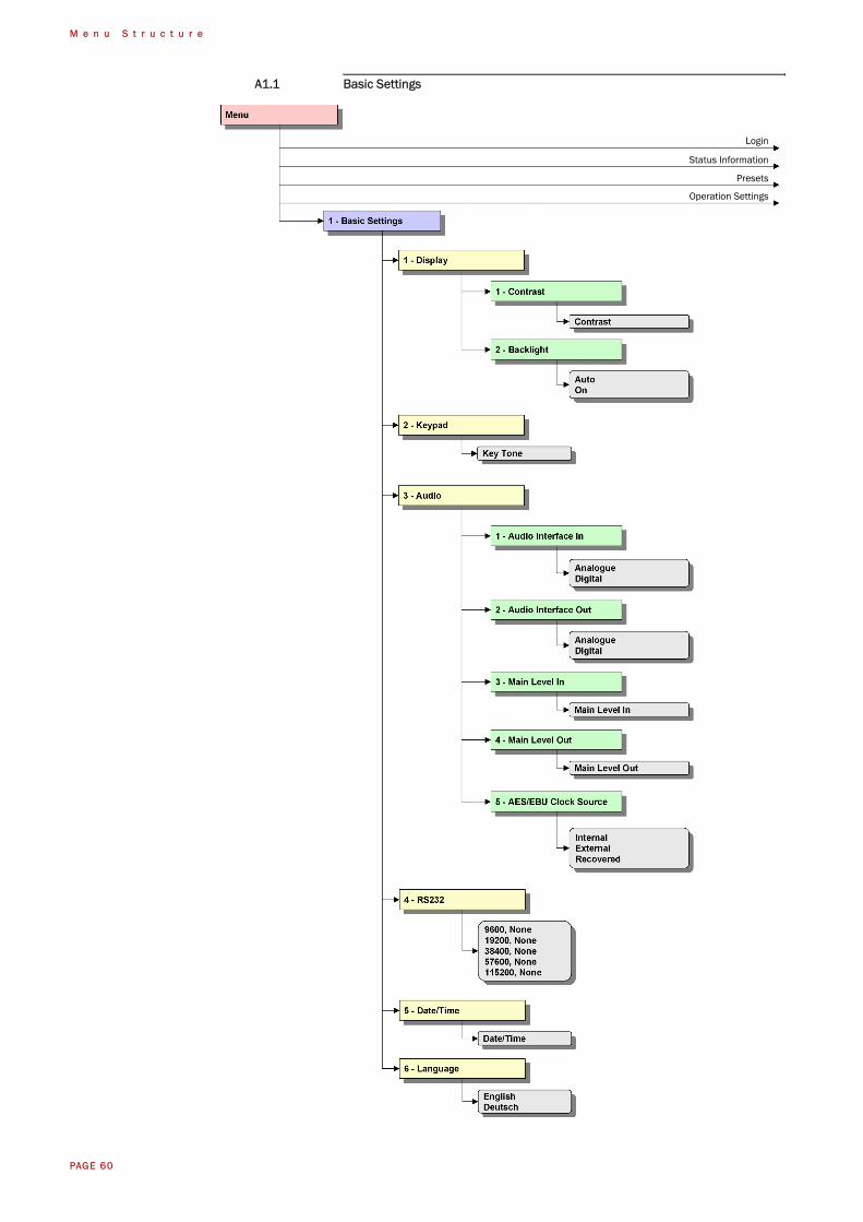
– Basic Settings
– Operation Settings
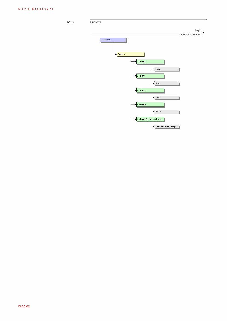
– Presets
– Status information
– Login
If you use an Administrator and/or User Password, the display looks as it is de-scribed below:
(1) Only Administrator Password configured: The password must be entered for changes to the basic settings and operation settings only. Immediately available menus:
– Presets
– Status information
– Login
(2) Only User Password configured (instead of Menu, Login is displayed): Thepassword must always be entered. Subsequently, all menus are available.
(3) User and Administrator Password configured (instead of Menu Login is dis-played):
– User Password is entered: The menus Presets, Status information and Login are available
– Administrator Password is entered: All menus are available.
NOTICE Please note that depending on the selected operating mode some menu itemsare not displayed.
NOTICE There is no differentiation between upper and lower case for the password entry.
PAGE 60
M e n u S t r u c t u r e
A1.1 Basic Settings
Status Information
Login
Presets
Operation Settings

PAGE 61
M e n u S t r u c t u r e
A1.2 Operation Settings
Status Information
Login
Presets
PAGE 62
M e n u S t r u c t u r e
A1.3 Presets
Status InformationLogin
PAGE 63
M e n u S t r u c t u r e
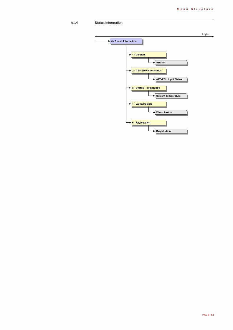
A1.4 Status Information
Login
PAGE 64
M e n u S t r u c t u r e
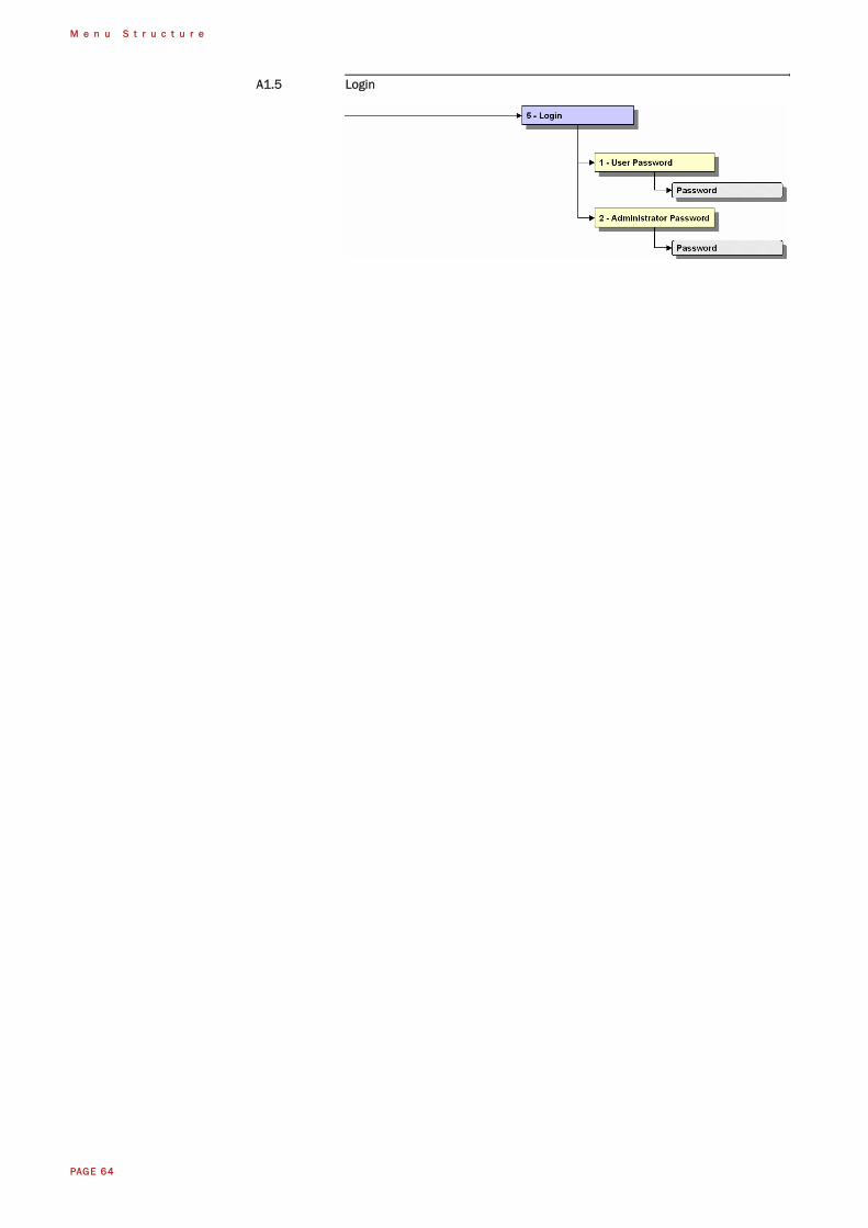
A1.5 Login
PAGE 65
I n t e r f a c e s
A 2 I N T E R F A C E S
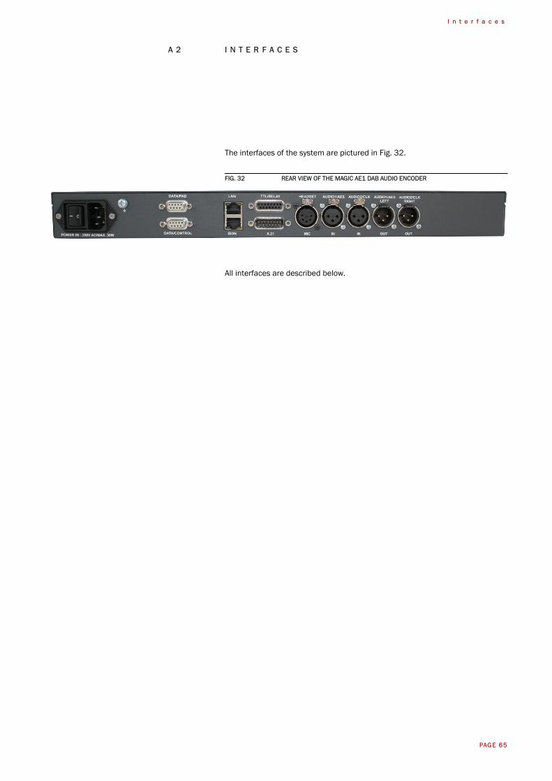
The interfaces of the system are pictured in Fig. 32.
FIG. 32 REAR VIEW OF THE MAGIC AE1 DAB AUDIO ENCODER
All interfaces are described below.
PAGE 66
I n t e r f a c e s
A2.1 Control and data interfaces
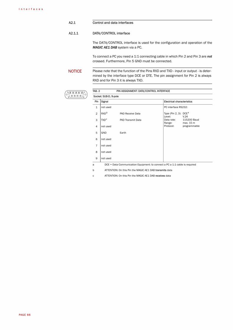
A2.1.1 DATA/CONTROL interface
The DATA/CONTROL interface is used for the configuration and operation of theMAGIC AE1 DAB system via a PC.
To connect a PC you need a 1:1 connecting cable in which Pin 2 and Pin 3 are notcrossed. Furthermore, Pin 5 GND must be connected.
NOTICE Please note that the function of the Pins RXD and TXD - input or output - is deter-mined by the interface type DCE or DTE. The pin assignment for Pin 2 is alwaysRXD and for Pin 3 it is always TXD.
TAB. 2 PIN ASSIGNMENT: DATA/CONTROL INTERFACE
Socket: SUB-D, 9-pole
Pin Signal Electrical characteristics
1 not used PC interface RS232:
Type (Pin 2, 3): DCEa
Level: V.24Data rate: 115200 BaudRange: max. 15 mProtocol: programmable
a DCE = Data Communication Equipment: to connect a PC a 1:1 cable is required
2 RXDb PAD Receive Data
b ATTENTION: On this Pin the MAGIC AE1 DAB transmits data
3 TXDc PAD Transmit Data
c ATTENTION: On this Pin the MAGIC AE1 DAB receives data
4 not used
5 GND Earth
6 not used
7 not used
8 not used
9 not used
5 1
9 6
PAGE 67
I n t e r f a c e s
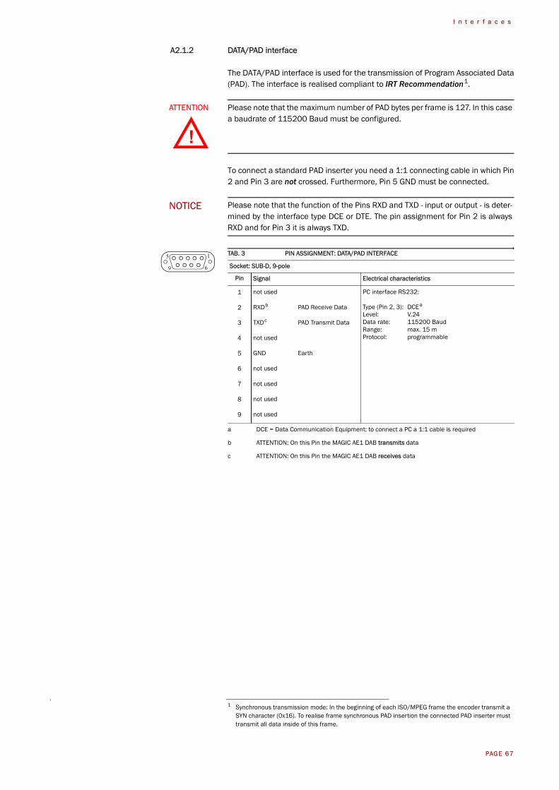
A2.1.2 DATA/PAD interface
The DATA/PAD interface is used for the transmission of Program Associated Data(PAD). The interface is realised compliant to IRT Recommendation1.
To connect a standard PAD inserter you need a 1:1 connecting cable in which Pin2 and Pin 3 are not crossed. Furthermore, Pin 5 GND must be connected.
ATTENTION Please note that the maximum number of PAD bytes per frame is 127. In this casea baudrate of 115200 Baud must be configured.
1 Synchronous transmission mode: In the beginning of each ISO/MPEG frame the encoder transmit a SYN character (0x16). To realise frame synchronous PAD insertion the connected PAD inserter must transmit all data inside of this frame.
NOTICE Please note that the function of the Pins RXD and TXD - input or output - is deter-mined by the interface type DCE or DTE. The pin assignment for Pin 2 is alwaysRXD and for Pin 3 it is always TXD.
TAB. 3 PIN ASSIGNMENT: DATA/PAD INTERFACE
Socket: SUB-D, 9-pole
Pin Signal Electrical characteristics
1 not used PC interface RS232:
Type (Pin 2, 3): DCEa
Level: V.24Data rate: 115200 BaudRange: max. 15 mProtocol: programmable
a DCE = Data Communication Equipment: to connect a PC a 1:1 cable is required
2 RXDb PAD Receive Data
b ATTENTION: On this Pin the MAGIC AE1 DAB transmits data
3 TXDc PAD Transmit Data
c ATTENTION: On this Pin the MAGIC AE1 DAB receives data
4 not used
5 GND Earth
6 not used
7 not used
8 not used
9 not used
!
5 1
9 6
PAGE 68
I n t e r f a c e s
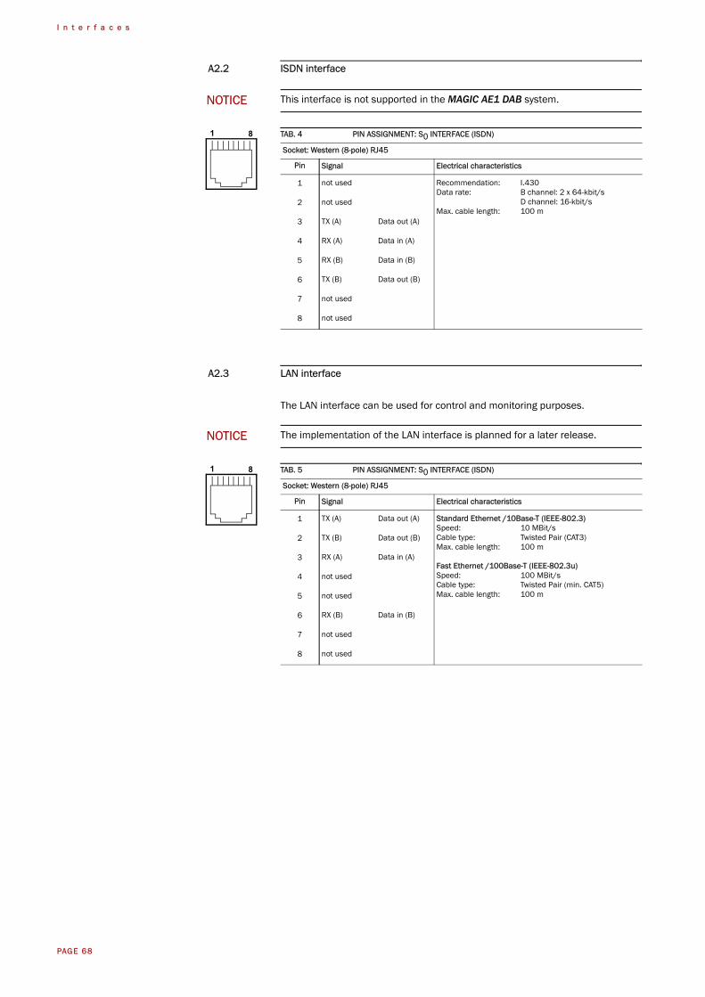
A2.2 ISDN interface
A2.3 LAN interface
The LAN interface can be used for control and monitoring purposes.
NOTICE This interface is not supported in the MAGIC AE1 DAB system.
TAB. 4 PIN ASSIGNMENT: S0 INTERFACE (ISDN)
Socket: Western (8-pole) RJ45
Pin Signal Electrical characteristics
1 not used Recommendation: I.430Data rate: B channel: 2 x 64-kbit/s
D channel: 16-kbit/sMax. cable length: 100 m
2 not used
3 TX (A) Data out (A)
4 RX (A) Data in (A)
5 RX (B) Data in (B)
6 TX (B) Data out (B)
7 not used
8 not used
NOTICE The implementation of the LAN interface is planned for a later release.
TAB. 5 PIN ASSIGNMENT: S0 INTERFACE (ISDN)
Socket: Western (8-pole) RJ45
Pin Signal Electrical characteristics
1 TX (A) Data out (A) Standard Ethernet /10Base-T (IEEE-802.3)Speed: 10 MBit/sCable type: Twisted Pair (CAT3)Max. cable length: 100 m
Fast Ethernet /100Base-T (IEEE-802.3u)Speed: 100 MBit/sCable type: Twisted Pair (min. CAT5)Max. cable length: 100 m
2 TX (B) Data out (B)
3 RX (A) Data in (A)
4 not used
5 not used
6 RX (B) Data in (B)
7 not used
8 not used
1 8
1 8
PAGE 69
I n t e r f a c e s
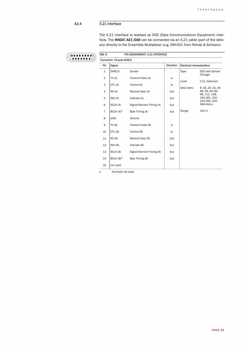
A2.4 X.21 interface
The X.21 interface is realised as DCE (Data Communications Equipment) inter-face. The MAGIC AE1 DAB can be connected via an X.21 cable (part of the deliv-ery) directly to the Ensemble Multiplexer (e.g. DM-001 from Rohde & Schwarz).
TAB. 6 PIN ASSIGNMENT: X.21 INTERFACE
Connector: 15-pole SUB-D
Pin Signal Direction Electrical characteristics
1 SHIELD Screen Type: DCE with GenderChanger
Level: V.11, balanced
Data rates: 8, 16, 24, 32, 40,48, 56, 64, 80, 96, 112, 128, 144,160, 192,224,256, 320,384-kbit/s
Range: 100 m
2 TX (A) Transmit Data (A) In
3 CTL (A) Control (A) In
4 RX (A) Receive Data (A) Out
5 IND (A) Indicate (A) Out
6 SCLK (A) Signal Element Timing (A) Out
7 BCLK (A)a Byte Timing (A)
a Normally not used
Out
8 GND Ground
9 TX (B) Transmit Data (B) In
10 CTL (B) Control (B) In
11 RX (B) Receive Data (B) Out
12 IND (B) Indicate (B) Out
13 SCLK (B) Signal Element Timing (B) Out
14 BCLK (B)a Byte Timing (B) Out
15 not used
81
159
PAGE 70
I n t e r f a c e s
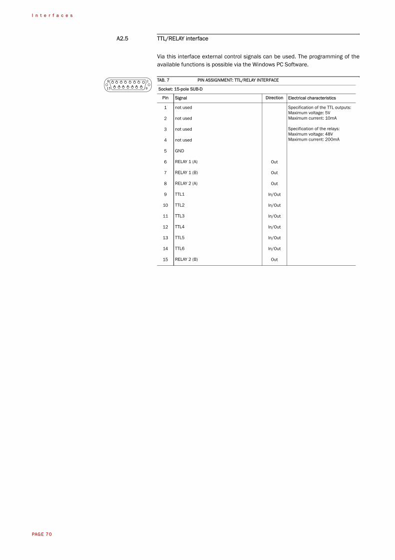
A2.5 TTL/RELAY interface
Via this interface external control signals can be used. The programming of theavailable functions is possible via the Windows PC Software.
TAB. 7 PIN ASSIGNMENT: TTL/RELAY INTERFACE
Socket: 15-pole SUB-D
Pin Signal Direction Electrical characteristics
1 not used Specification of the TTL outputs:Maximum voltage: 5VMaximum current: 10mA
Specification of the relays:Maximum voltage: 48VMaximum current: 200mA
2 not used
3 not used
4 not used
5 GND
6 RELAY 1 (A) Out
7 RELAY 1 (B) Out
8 RELAY 2 (A) Out
9 TTL1 In/Out
10 TTL2 In/Out
11 TTL3 In/Out
12 TTL4 In/Out
13 TTL5 In/Out
14 TTL6 In/Out
15 RELAY 2 (B) Out
18
915
PAGE 71
I n t e r f a c e s
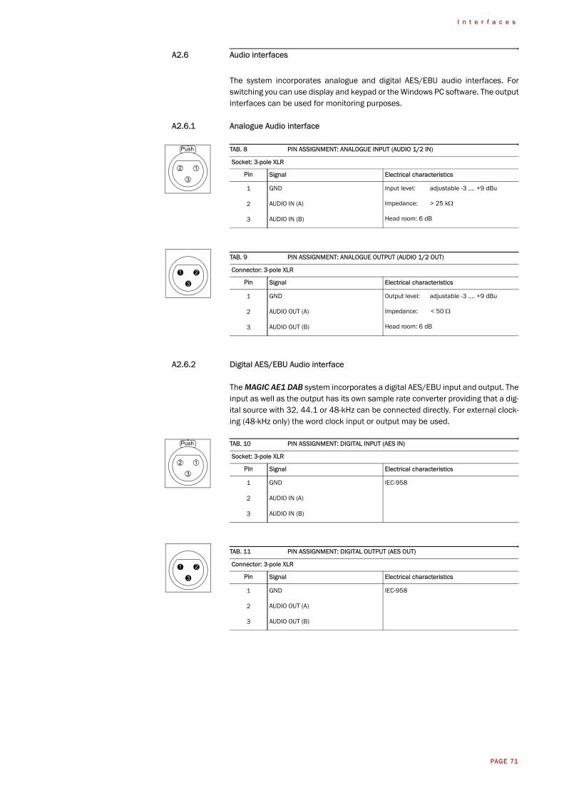
A2.6 Audio interfaces
The system incorporates analogue and digital AES/EBU audio interfaces. Forswitching you can use display and keypad or the Windows PC software. The outputinterfaces can be used for monitoring purposes.
A2.6.1 Analogue Audio interface
A2.6.2 Digital AES/EBU Audio interface
The MAGIC AE1 DAB system incorporates a digital AES/EBU input and output. Theinput as well as the output has its own sample rate converter providing that a dig-ital source with 32, 44.1 or 48-kHz can be connected directly. For external clock-ing (48-kHz only) the word clock input or output may be used.
TAB. 8 PIN ASSIGNMENT: ANALOGUE INPUT (AUDIO 1/2 IN)
Socket: 3-pole XLR
Pin Signal Electrical characteristics
1 GND Input level: adjustable -3 .... +9 dBu
Impedance: > 25 kΩ
Head room: 6 dB
2 AUDIO IN (A)
3 AUDIO IN (B)
TAB. 9 PIN ASSIGNMENT: ANALOGUE OUTPUT (AUDIO 1/2 OUT)
Connector: 3-pole XLR
Pin Signal Electrical characteristics
1 GND Output level: adjustable -3 .... +9 dBu
Impedance: < 50 Ω
Head room: 6 dB
2 AUDIO OUT (A)
3 AUDIO OUT (B)
TAB. 10 PIN ASSIGNMENT: DIGITAL INPUT (AES IN)
Socket: 3-pole XLR
Pin Signal Electrical characteristics
1 GND IEC-958
2 AUDIO IN (A)
3 AUDIO IN (B)
TAB. 11 PIN ASSIGNMENT: DIGITAL OUTPUT (AES OUT)
Connector: 3-pole XLR
Pin Signal Electrical characteristics
1 GND IEC-958
2 AUDIO OUT (A)
3 AUDIO OUT (B)
Push
12
3
21
3
Push
12
3
21
3
PAGE 72
I n t e r f a c e s
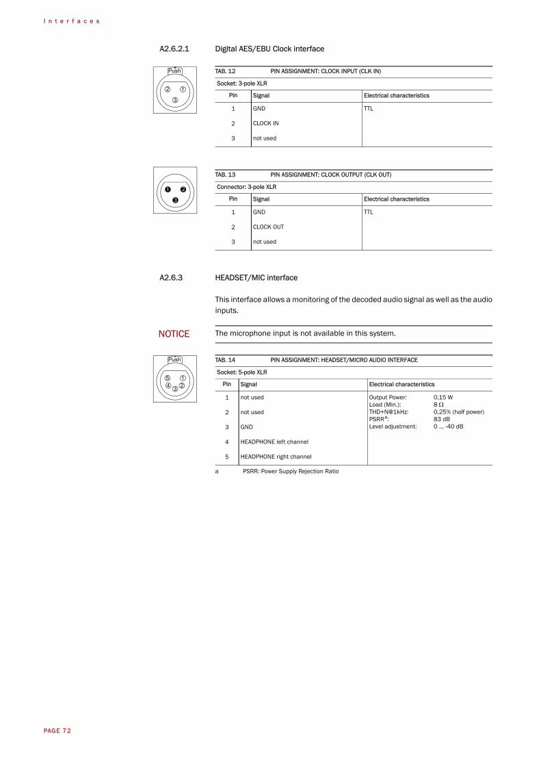
A2.6.2.1 Digital AES/EBU Clock interface
A2.6.3 HEADSET/MIC interface
This interface allows a monitoring of the decoded audio signal as well as the audioinputs.
TAB. 12 PIN ASSIGNMENT: CLOCK INPUT (CLK IN)
Socket: 3-pole XLR
Pin Signal Electrical characteristics
1 GND TTL
2 CLOCK IN
3 not used
TAB. 13 PIN ASSIGNMENT: CLOCK OUTPUT (CLK OUT)
Connector: 3-pole XLR
Pin Signal Electrical characteristics
1 GND TTL
2 CLOCK OUT
3 not used
NOTICE The microphone input is not available in this system.
TAB. 14 PIN ASSIGNMENT: HEADSET/MICRO AUDIO INTERFACE
Socket: 5-pole XLR
Pin Signal Electrical characteristics
1 not used Output Power: 0,15 WLoad (Min.): 8 ΩTHD+N@1kHz: 0,25% (half power)PSRRa: 83 dBLevel adjustment: 0 ... -40 dB
a PSRR: Power Supply Rejection Ratio
2 not used
3 GND
4 HEADPHONE left channel
5 HEADPHONE right channel
Push
12
3
21
3
Push
15
3 24
PAGE 73
T e c h n i c a l D a t a
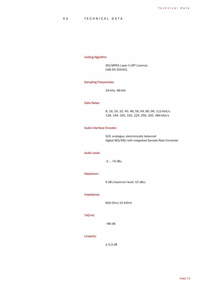
A 3 T E C H N I C A L D A T A
Coding Algorithm
ISO/MPEG Layer II (IRT Licence)DAB EN 300401
Sampling Frequencies:
24-kHz, 48-kHz
Data Rates:
8, 16, 24, 32, 40, 48, 56, 64, 80, 96, 112-kbit/s128, 144, 160, 192, 224, 256, 320, 384-kbit/s
Audio Interface Encoder:
XLR, analogue, electronically balanceddigital AES/EBU with integrated Sample Rate Converter
Audio Level:
-3 ... +9 dBu
Headroom:
6 dB (maximum level: 15 dBu)
Impedance:
600 Ohm/15 KOhm
THD+N:
~86 dB
Linearity:
± 0,3 dB
PAGE 74
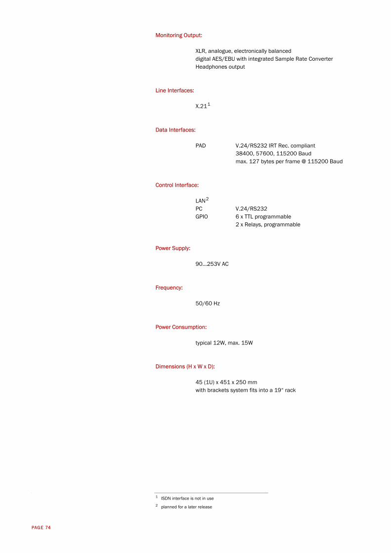
Monitoring Output:
XLR, analogue, electronically balanceddigital AES/EBU with integrated Sample Rate ConverterHeadphones output
Line Interfaces:
X.211
Data Interfaces:
PAD V.24/RS232 IRT Rec. compliant38400, 57600, 115200 Baudmax. 127 bytes per frame @ 115200 Baud
Control Interface:
LAN2
PC V.24/RS232GPIO 6 x TTL programmable
2 x Relays, programmable
Power Supply:
90...253V AC
Frequency:
50/60 Hz
Power Consumption:
typical 12W, max. 15W
Dimensions (H x W x D):
45 (1U) x 451 x 250 mmwith brackets system fits into a 19“ rack
1 ISDN interface is not in use2 planned for a later release
PAGE 75
G e n e r a l
A 4 G E N E R A L
A4.1 Ordering numbers
MAGIC AE1 DAB 800401
Accessories
-
Software Options
-
A4.2 Scope of delivery
– MAGIC AE1 DAB
– CD MAGIC AE1 DAB Updates (ID: 430283)
– Mains power supply cable
– RS232 cable
– X.21 interface cable 15-pole SUB-D, 2 x Socket
– 19’’ Mounting Brackets
– Manual
A4.3 Declaration of Conformity
You will find the declaration of conformity at the end of this manual.

PAGE 76
G e n e r a l
PAGE 77
S e r v i c e I n f o r m a t i o n
A 5 S E R V I C E I N F O R M A T I O N
A5.1 Software Updates
Free Software Updates you will find on our Homepage under
http://www.avt-nbg.de
Ident No.: 430282
A5.2 Support
You can contact our Support via email or by telephone:
+49 911 5271-160 (09:00h - 17:00h)
To deal with your problem efficiently please note the factory number of the unit aswell as the software version that you use.
A5.3 Repairs
If, contrary to expectations, your unit is defective please fill in the attached statusreport and send the unit to the following address:
AVT Audio Video Technologies GmbH- Repairs -Nordostpark 12D-90411 NuernbergGermany

PAGE 78
S e r v i c e I n f o r m a t i o n
PAGE 79
I n d e x
I N D E X
Symbols
.pst 47, 48
Numerics
1 U 15115200 25, 3319 " 1919" rack 1519-inch-rack 1938400 2557600 25, 339600 33
A
A/D D/A Converter 1 55A/D D/A Converter 2 55About MAGIC AE1 DAB 57Accessories 75Activate PAD 25, 36Active 25Administrator 44, 59ae1dab.ssw 53AES/EBU 24, 56, 71AES/EBU Interface 39AES/EBU status 56Air humidity 19Alarm 55Alarm Counter Reset 55Ambient temperature 19Analogue 24, 25, 39Audio 1/AES IN 39Audio 2/CLK IN 39Audio 2/CLK OUT 39Audio Input 39Audio input 24, 25Audio interface 24Audio Output 39Audio output 24, 25Audio settings 24, 25Auto 37
B
Backlight 37Basic configurations 23Basic Settings 37Baudrate 25
Browse 53
C
character 47Clock 39Clock Source of digital output 39COM Port 33COM-Port 29Configuration 29, 33, 34, 44, 47,
59Confirm Password 44Connect 42, 43Connecting cable 66, 67Connection Status 42, 43contact information 57Contrast 37Conventions 14
D
Data Bits 33Date/Time 27Deactivation 23Declaration of Conformity 75, 83Decoder not synced 56Decoder running 56Decoder sampling clock 56Delete 47Delete Preset 27Desktop device 19Digital 24, 39Direction 40Disconnect 42, 43Display 20, 37, 71Display illumination 23Download 53Dropping 26DSP Load 56DTE 66, 67Dual Channel 25, 35
E
Earthing 19Earthing screw 19edge change 40Edit 47Email 77EMC 19
PAGE 80
I n d e x
Enabled 37Encoder running 56Encoder sampling clock 56English 59Enter Password 49error counter 55Exit 32Export 32, 48Export All 48External 39External Power Supply 30Extras 45
F
Factory Number 49Factory Settings 54Features 49Firmware 53Firmware Version 57Fixed to High (5V) 42, 43FLASH EPROM 55Flash memory 53Front view 15, 30Function Code 40, 42, 43Functional elements 17
G
GPIO 40
H
Hardware error 55Hardware requirements 29Hardware Version 49Headphone 31Headroom 19, 71Homepage 77Hotline 77
I
Import 32, 47, 48Input 31, 40Install Software 29Installation 29Interface 65Internal 39IRT 36
J
Joint Stereo 25, 35
K
Key Tone 37
Keypad 71Keypad (9600 Baud) 37keypad lock 37
L
LCA 55Level In 39Level Out 39Load 27Load Preset 40Login 45, 59LSF 34
M
MAGIC AE1 DAB Software 23MAIN EEPROM 56Main menu 23, 26, 59Mains voltage 19Manage Presets 47Max LSF Rate 24Max Mono Rate 24Max. LSF Bitrate 34Max. Mono Bitrate 34Menu 37, 59Menu structure 23, 59Minimum requirements 29Monitoring 31Mono (L+R)/2 35Mono L 34Mono L+R/2 25Mono Left 25Mono Mode 25Mono R 35Mono Right 25Mounting brackets 19MPEG Parameter 24, 25
N
Names 59Navigation 20Negative edge 40New 27, 47NO CONNECTION 30
O
On 37ON AIR Nominal Level 39Operating buttons 20Operation 13Operation settings 59Operation Settings Presets 32Operational elements 20Options 49Ordering numbers 75Output 31, 40, 42
PAGE 81
I n d e x
Overheated 56
P
PAD 36PAD Interface 25Parity 33Password 44, 49, 59PC 66PC (19200 Baud) 33, 37PC (38400 Baud) 33PC Offline 30PC ONLINE 30PC Online 30PC ONLINE ALARM 30PC Software 71PC Version 57Phone book 59Port 33Positive edge 40, 42POTS 66POTS interface 66Power consumption 19Preset 27, 34, 37, 40Preset menu 27Presets 27, 45, 47, 59Program 31Program Name 31Progress 53Putting the system into operation
27
Q
QuickMenu 23
R
Rack 19Recovered 39Registration 49Relay 70Relay 1 43Relay 2 43Relay output 43Relays 40Repairs 77Resolution 20RS232 33
S
S0 interface 68Safety instructions 13Sample Rate Converter 24, 39,
71Save 27Scope of delivery 75Select 47
Serial cable 29Service 52Set Audio Line 40Setup 29setup.exe 29Softkey 20Software 23, 77Software Download 53Software Options 49Software Updates 77Software Versions 57space 47Standby mode 19Start 53Status 42, 43Status information 59Stereo 25, 35Stereo Mode 25Stop Bits 33Storage 13Subject Number 49Support 52, 77switch current 42switch voltage 42synchronous 39System Alarm 42, 43System alarm 55System alarms 55System Monitor 30, 45, 55System Panel 52System settings 24, 25, 59System Temperature 56System temperature 19
T
temperature 56Temperature Sensor 55Threshold values 19Time Keeper 55Transmission clock 24Transport 13TTL 40, 42, 43, 70TTL1 40TTL2 40TTL3 40
U
Updates 77USB Stick 47User 44, 59User Rights 44
V
Ventilation 19Version 57

PAGE 82
I n d e x
W
Warm start 50Warranty claim 19
X
X.21 clock 34, 56
Y
Year 49

Supplier’s name: AVT Audio Video Technologies GmbH
Supplier’s address: Nordostpark 12D-90411 NuernbergGermany
declares, that the product
Product name(s): MAGIC AE1 DAB
conforms to the standards of the following European directives:
Number/title: EN 60950 A4 Safety
The conformity is evidenced by strictly meeting the following standards:
Harmonized Standards: EN 55022, EN 55024,EN 300386,FCC Part 15 B
Place, date: Nuernberg, 20.06.2006
Name: Wilfried HECHT (Managing Director)
Legally binding signatures:
Phone: +49 911 5271-0
This declaration includes no warranty of properties.
The safety instructions specified in the product documentation delivered must be observed.
Dec
lara
tion
of C
onfo
rmity
DECLARATION OF CONFORMITY