Embed Size (px)
Citation preview

MAG Weldingof Unalloyed SteelsProcess Engineering andSelection of Shielding Gases
Shielding Gases:Classics and Trends
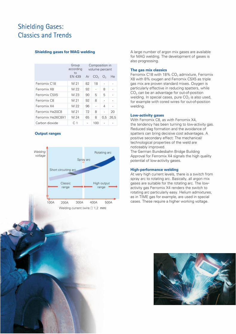
Shielding gases for MAG welding
Groupaccording
to
Composition involume percent
EN 439 Ar CO2 O2 He
Ferromix C18 M 21 82 18 - -
Ferromix X8 M 22 92 - 8 -
Ferromix C5X5 M 23 90 5 5 -
Ferromix C8 M 21 92 8 - -
Ferromix X4 M 22 96 - 4 -
Ferromix He20C8 M 21 72 8 - 20
Ferromix He26C8X1 M 24 65 8 0,5 26,5
Carbon dioxide C 1 - 100 - -
Output ranges
100A 200A 300A 400A 500A
Rotating arc
Spray arc
Short circuiting arc
Classicrange
Weldingvoltage
High outputrange
Welding current (wire ∅ 1,2 mm)
A large number of argon mix gases are availablefor MAG welding. The development of gases isalso progressing.
The gas mix classicsFerromix C18 with 18% CO2 admixture, FerromixX8 with 8% oxygen and Ferromix C5X5 as triplegas mix are proven standard mixes. Oxygen isparticularly effective in reducing spatters, whileCO2 can be an advantage for out-of-positionwelding. In special cases, pure CO2 is also used,for example with cored wires for out-of-positionwelding.
Low-activity gasesWith Ferromix C8, as with Ferromix X4,the tendency has been turning to low-activity gas.Reduced slag formation and the avoidance ofspatters can bring decisive cost advantages. Apositive secondary effect: The mechanical/technological properties of the weld arenoticeably improved.The German Bundesbahn Bridge BuildingApproval for Ferromix X4 signals the high qualitypotential of low-activity gases.
High-performance weldingAt very high current levels, there is a switch fromspray arc to rotating arc. Basically, all argon mixgases are suitable for the rotating arc. The low-activity gas Ferromix X4 renders the switch torotating arc particularly easy. Helium admixtures,as in TIME gas for example, are used in specialcases. These require a higher working voltage.

Wire diameter 1.0 or 1.2 mm?Solid wires are predominantly used. Mostly used is the 1.2 mm wireelectrode. This permits high melting performance in the normal position andis also suitable for thin sheets and out-of-position welding. Where thin sheetsand out-of-position welding predominate, a 1.0 mm electrode, which also hasa very high melting performance in normal position, is better. For workingexclusively on thin sheets, a 0.8-mm electrode is used. The 1.6-mm electrodeis favored for thick sheets in the normal position, but is often being replacedby high performance welding.
What shielding gas quantity is correct?In the short arc, at 150 A for example, the shielding gas setting is about 12-15 l/min, in the spray arc, at 300 A for example, 15-18 l/min. In the high-output arc above 350 A, this rises to 20-25 l/min. These volumes refer tonormal contact tip distances. If the component requires an increased contacttip distance, the gas volumes must be increased accordingly. There must notbe too much gas, however, else air is sucked in, leading to porosity. The bestregulating characteristics here are provided by cylinder reducing valves withvariable flowmeters (rotameters).
Melting performance – possibilities and limitsMAG welding is today progressing into new performance ranges. 380 Amanually and 420 A mechanically are common practice with the 1.2-mm wireelectrode and can achieve melting rates of 10 to 12 kg/h. Even higher melt-off performances are reached in the rotating arc range, also known as TIMEwelding. On a metallurgical basis melting rates of more than 20 kg/h arepossible with MAG welding.
The torch: gas or water-cooled?For exclusive thin sheet working with short switch-on duration, i.e. up to the220-A range, gas-cooled systems are the right choice. At a current of 250 Awith the 1.0-mm wire electrode, water cooling is already to berecommended. Water-cooled high-power torches are also considerably lighterand easier to handle than corresponding gas-cooled torches for high output.Furthermore, water cooling always offers a reserve, should the output gohigher than planned.
Little slag, no spattersClean seams with no reworking: herefore, everything has to be right. High-quality power sources, low-tolerance wires and also, of course, theright adjustment technology. The spatter-prone mixed arc range can becompletely avoided by the right choice of wire with the correct diameter. Inthe case of extreme low-spatter requirements, pulse technology can be used.Low-activity gases offer the best preconditions to minimize slag and spatters.
Galvanized sheets: MIG brazingTechnical advances can throw up new questions. Galvanization, not only inthe automobile industry a sign of enhanced quality and long service life,leads, through the vaporization of zinc, to considerable pore formation andspattering during MAG welding. For zinc plating up to 20 µm thick, analternative here is MIG brazing . A bronze wireelectrode (e.g. CuSi3) is usedas filler metal. For typical applications in the thin sheet range, brazing iscarried out at less than 100 A, sometimes pulsed. A beneficial side effect:there is no need for regalvanization, as the MIG brazed seam is corrosionresistant.
Process technology in MAG welding

Support, Delivery, Service
MESSER offers a comprehensive program ofgases, which is not always a matter of course.But that is far from all.
We can give advice on the choice of process oron questions of mechanization, we can tell youwhich type of supply – cylinder, bundle or coldevaporator liquid supply – is the right one for you.We would also be glad to talk to you about thecost-saving potentials which may exist foryour company in welding, cutting and relatedprocesses.
Information and training material for yourcompany is naturally all included in the wayof technical films which you can borrow free ofcharge, technical articles, brochures and specialinfo on the many everyday questions relating todetails of welding and cutting technology.
We will be happy to provide you with anyinformation you may require, please contact:Tel.: +49 (0) 21 51 7811-234Tel.: +49 (0) 21 51 7811-235Tel.: +49 (0) 21 51 7811-236
Messer Group GmbHGahlingspfad 31
47803 KrefeldTel. +49 2151 7811-0
Fax +49 2151 [email protected]
www.messergroup.com
ManagementHolding
Our Technical Centres:1) Krefeld2) Dällikon3) Budapest4) Shanghai
09/05 / 1.EN1.204


![[Welding] MIG-MAG Welding Guide - Lincoln Electric (eBook_ 48 Pages)](https://img.pdfslide.us/doc/110x75/541535697bef0a7c3f8b4713/welding-mig-mag-welding-guide-lincoln-electric-ebook-48-pages.jpg)