Embed Size (px)
Citation preview
MAE 322 Machine Design
Dr. Hodge Jenkins
Mercer University
What is this ‘Machine Design’ course really about?
• What you will learn: How to design machine elements • 1) Design so they won’t break under varying loads
• 2) How to apply and select standard machine components
• If you apply all you learn here, you can still build an awful machine that does not work well. 1) Function can be very different from breakage.
• A good functional machine takes more than just good parts. • But, you need good parts and components to build a good functional
machine.
You will learn: Component Design Philosophies and ‘Guidelines”
•General, good approaches to design machine elements not to fail under various loadings • Transmit power, torque or force,
• Transform kinematic motion
• Common Commercial Standards
•Design Rules of thumb (experience)
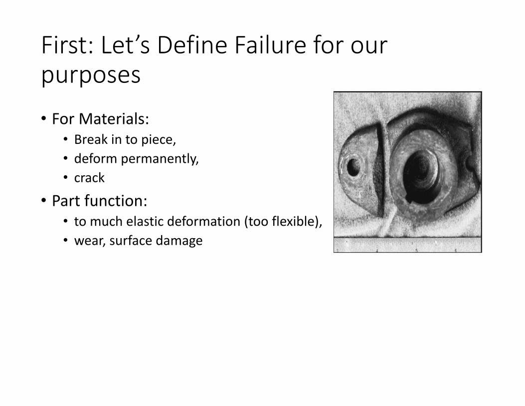
First: Let’s Define Failure for our purposes
• For Materials: • Break in to piece,
• deform permanently,
• crack
• Part function: • to much elastic deformation (too flexible),
• wear, surface damage
Failure: Stress > Strength
• Typically we will limit ourselves to examining stress
• Stress: 1-D, 2-D, 3-D • σ= Normal (compression or tension),
• τ= Shear
• Loading: Static, Dynamic, Cyclic
• Strength: strength values for materials, determined experimentally
Static Material Strength
• Usually necessary to design using published strength values
• Experimental test data is better, but generally only warranted for large quantities or when failure is very costly (in time, expense, or life) (e.g., aircraft nuclear reactors)
• Methods are needed to safely and appropriately use published strength values for a variety of situations • In many instances it use depends on whether a material is
ductile or brittle
Shigley’s Mechanical Engineering Design
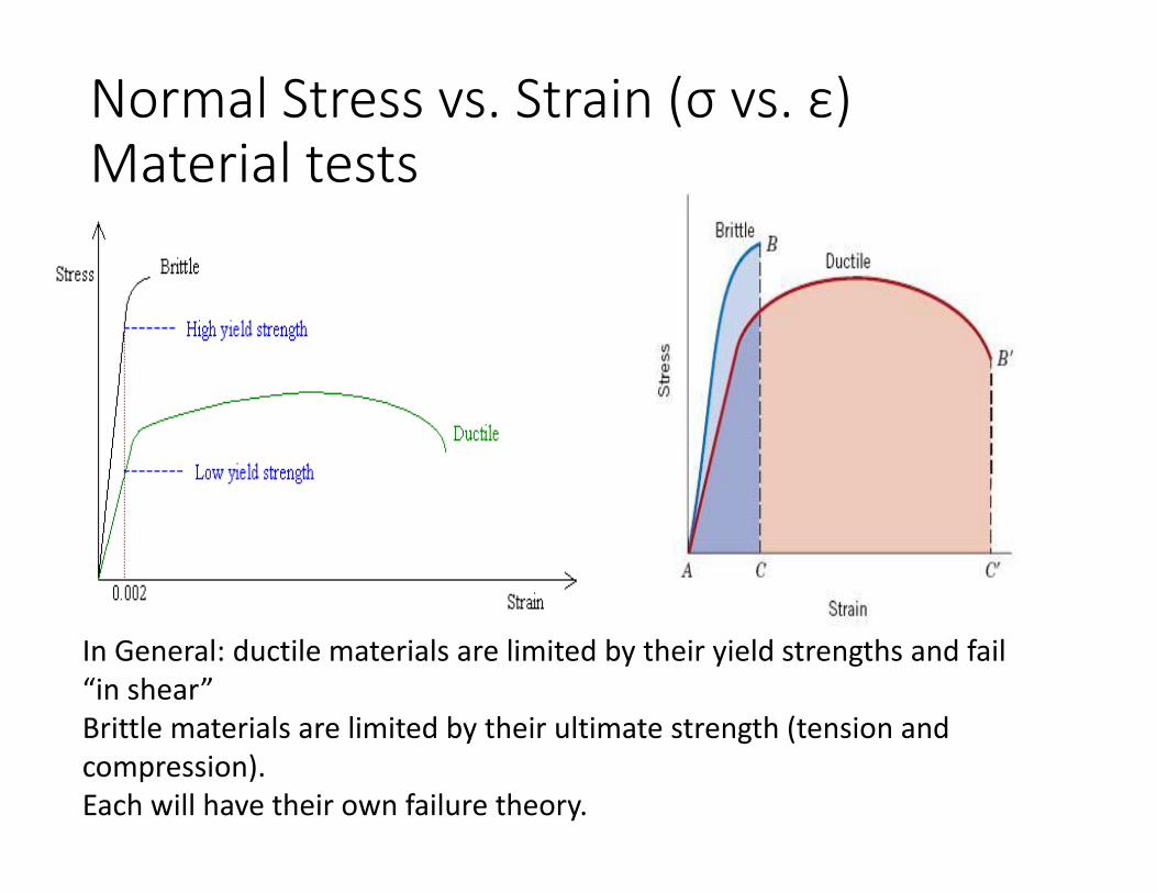
Normal Stress vs. Strain (σ vs. ε) Material tests
In General: ductile materials are limited by their yield strengths and fail “in shear” Brittle materials are limited by their ultimate strength (tension and compression). Each will have their own failure theory.
Need for Static Failure Theories
• Failure theories propose appropriate means of comparing multi-axial stress states to single strength
• Usually based on some hypothesis of what aspect of the stress state is critical
• Some failure theories have gained recognition of usefulness for various situations
• SY = material yield stress in uniaxial tension
• SUT= material ultimate tensile stress in uniaxial tension
Shigley’s Mechanical Engineering Design
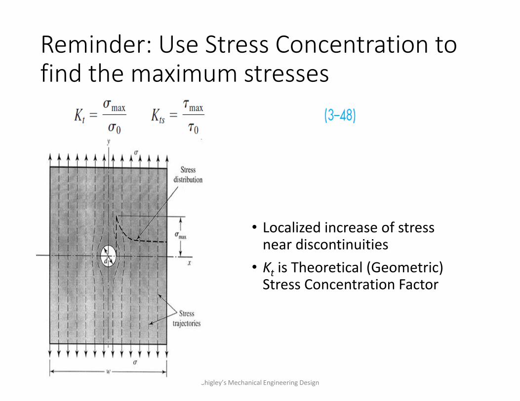
Reminder: Use Stress Concentration to find the maximum stresses
• Localized increase of stress near discontinuities
• Kt is Theoretical (Geometric) Stress Concentration Factor
Shigley’s Mechanical Engineering Design
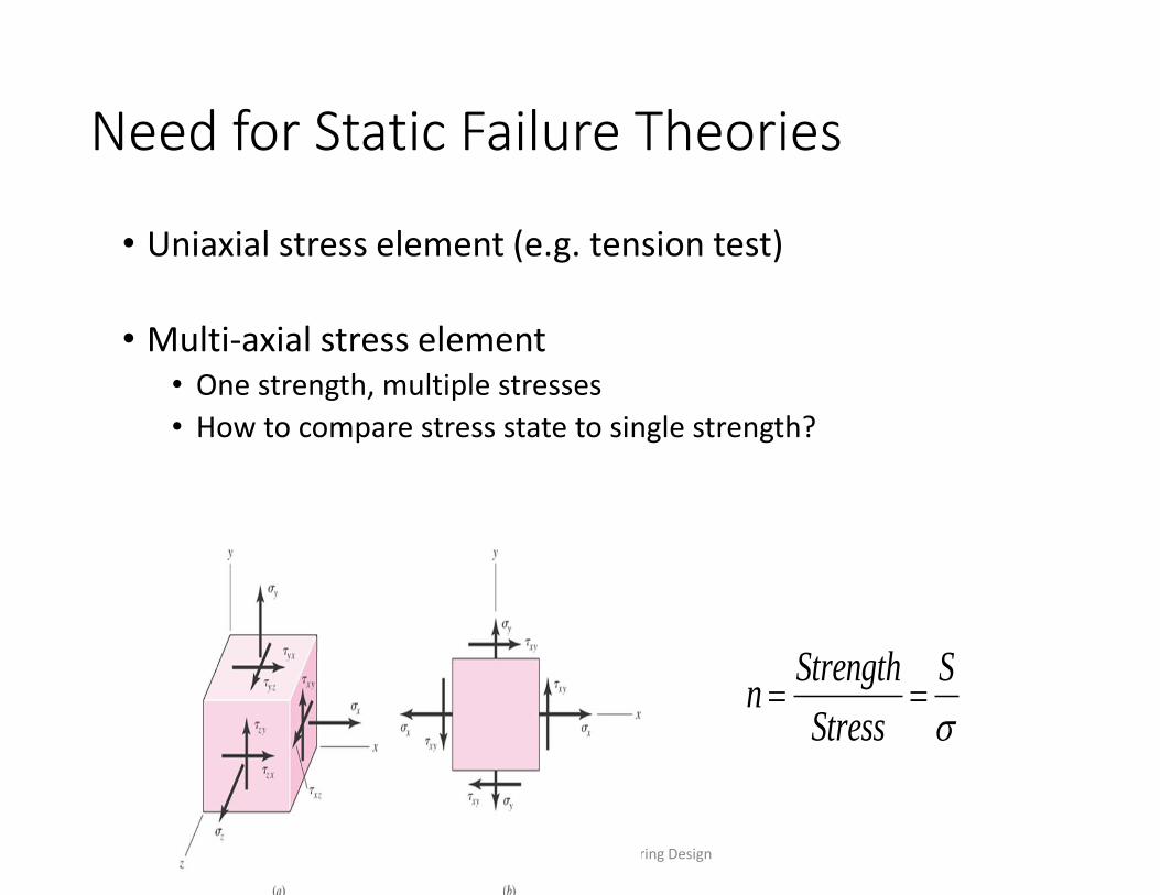
Need for Static Failure Theories
• Uniaxial stress element (e.g. tension test)
• Multi-axial stress element • One strength, multiple stresses
• How to compare stress state to single strength?
Shigley’s Mechanical Engineering Design
Strength Sn
Stress
Maximum Normal (Principal) Stress Theory
• Theory: Yielding begins when the maximum principal stress in a stress element exceeds the yield strength.
• n=factor of safety
• For any stress element, use Mohr’s circle to find the principal stresses.
• Compare the largest principal stress to the yield strength.
• Often the first theory to be proposed by engineering students.
• Is it a good theory?...... Depends.
Shigley’s Mechanical Engineering Design
𝑛 =𝑆𝑡𝑟𝑒𝑛𝑔𝑡ℎ
𝑆𝑡𝑟𝑒𝑠𝑠=
𝑆𝑌𝜎𝑀𝐴𝑋
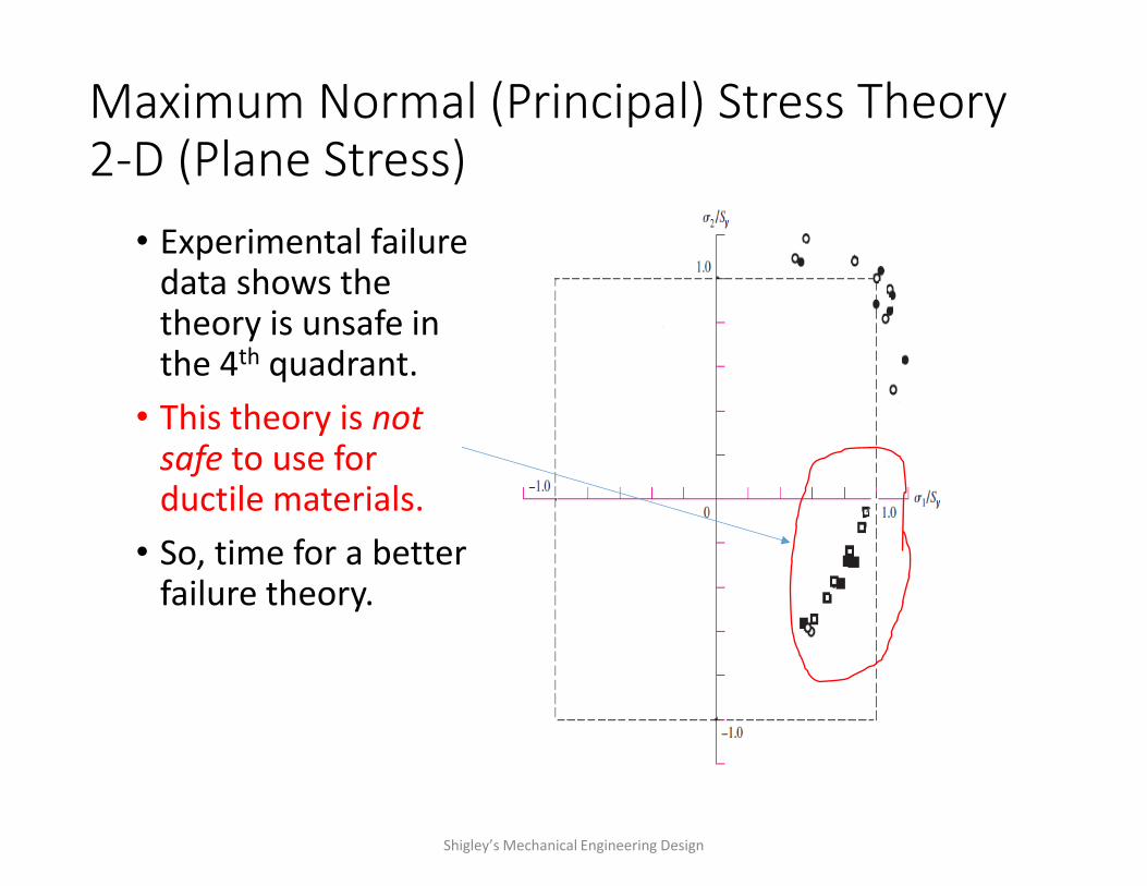
Maximum Normal (Principal) Stress Theory 2-D (Plane Stress)
• Experimental failure data shows the theory is unsafe in the 4th quadrant.
• This theory is not safe to use for ductile materials.
• So, time for a better failure theory.
Shigley’s Mechanical Engineering Design
Statics Load Failure Theories to Study and Understand
•Maximum Normal Stress
•Maximum Shear Stress
•Distortion Energy
•Coulomb-Mohr
Maximum Shear Stress Theory (MSS) • Theory: Yielding begins when the maximum
shear stress in a stress element exceeds the maximum shear stress in a tension test specimen of the same material when that specimen begins to yield.
• For a tension test specimen, the maximum shear stress is 1 /2.
• At yielding, when 1 = Sy, the maximum shear stress is Sy /2 .
• Could restate the theory as follows: • Theory: Yielding begins when the maximum shear
stress in a stress element exceeds Sy/2.
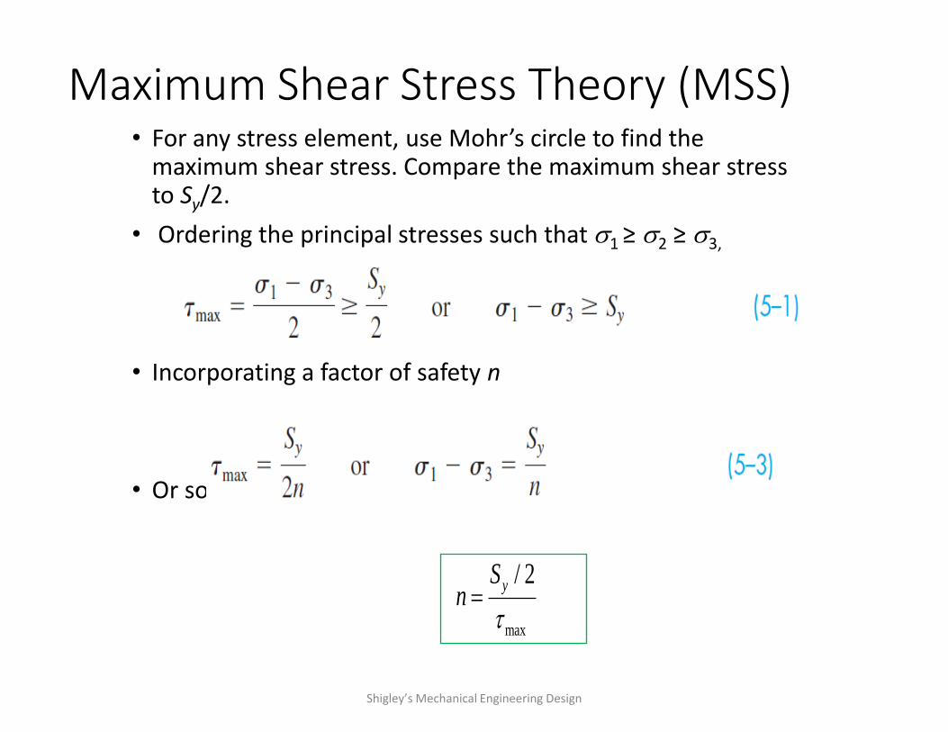
Maximum Shear Stress Theory (MSS) • For any stress element, use Mohr’s circle to find the
maximum shear stress. Compare the maximum shear stress to Sy/2.
• Ordering the principal stresses such that 1 ≥ 2 ≥ 3,
• Incorporating a factor of safety n
• Or solving for factor of safety
Shigley’s Mechanical Engineering Design
max
/ 2ySn
Maximum Shear Stress Theory (MSS) • To compare to experimental data, express max in
terms of principal stresses and plot.
• To simplify, consider a plane stress state
• Let A and B represent the two non-zero principal stresses, then order them with the zero principal stress such that 1 ≥ 2 ≥ 3
• Assuming A ≥ B there are three cases to consider • Case 1: A ≥ B ≥ 0
• Case 2: A ≥ 0 ≥ B
• Case 3: 0 ≥ A ≥ B
Shigley’s Mechanical Engineering Design
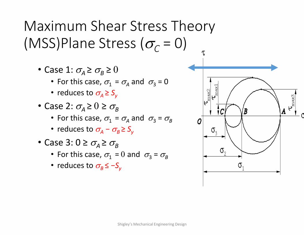
Maximum Shear Stress Theory (MSS)Plane Stress (C = 0)
• Case 1: A ≥ B ≥ 0
• For this case, 1 = A and 3 = 0
• reduces to A ≥ Sy
• Case 2: A ≥ 0 ≥ B
• For this case, 1 = A and 3 = B
• reduces to A − B ≥ Sy
• Case 3: 0 ≥ A ≥ B
• For this case, 1 = 0 and 3 = B
• reduces to B ≤ −Sy
Shigley’s Mechanical Engineering Design
Maximum Shear Stress Theory (MSS)
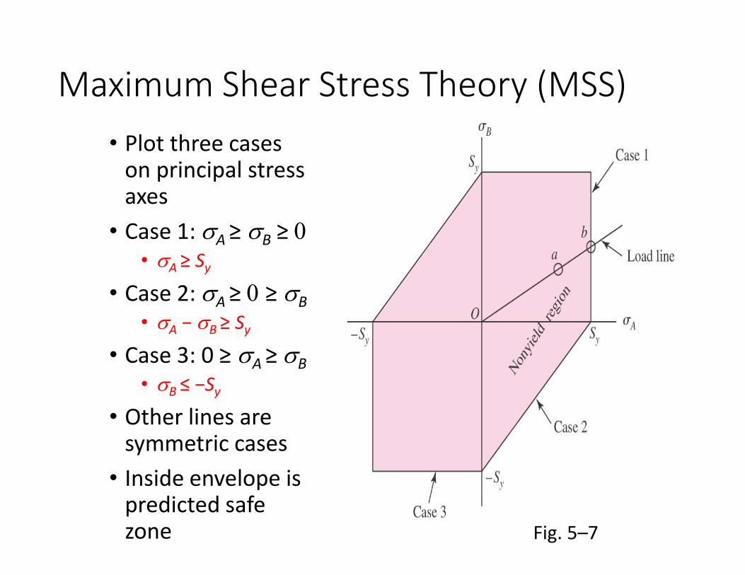
• Plot three cases on principal stress axes
• Case 1: A ≥ B ≥ 0
• A ≥ Sy
• Case 2: A ≥ 0 ≥ B
• A − B ≥ Sy
• Case 3: 0 ≥ A ≥ B
• B ≤ −Sy
• Other lines are symmetric cases
• Inside envelope is predicted safe zone
Fig. 5–7
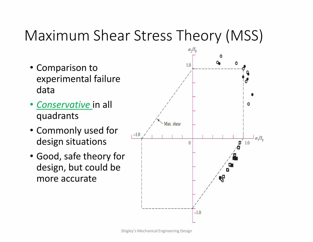
Maximum Shear Stress Theory (MSS)
• Comparison to experimental failure data
• Conservative in all quadrants
• Commonly used for design situations
• Good, safe theory for design, but could be more accurate
Shigley’s Mechanical Engineering Design
End Lecture 1