Embed Size (px)
Citation preview
Gears and Gearing
Part 2
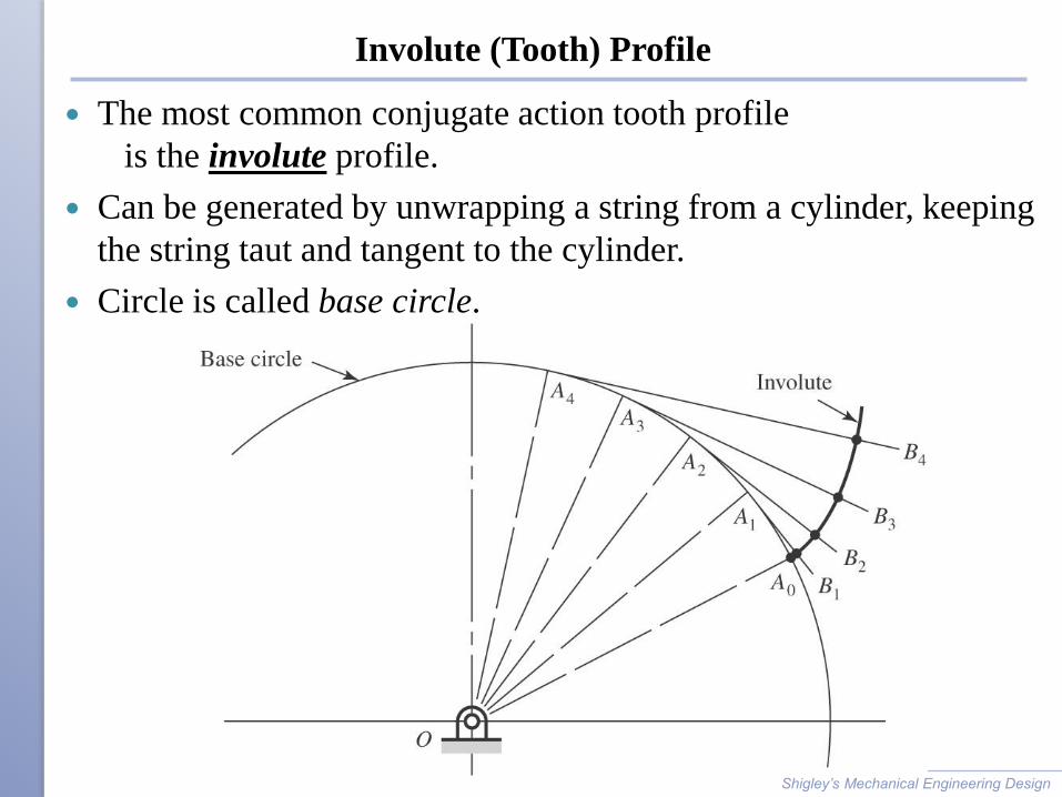
Involute (Tooth) Profile
The most common conjugate action tooth profile
is the involute profile.
Can be generated by unwrapping a string from a cylinder, keeping
the string taut and tangent to the cylinder.
Circle is called base circle.
Shigley’s Mechanical Engineering Design
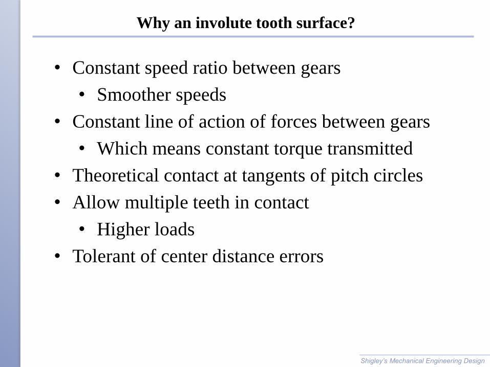
Why an involute tooth surface?
Shigley’s Mechanical Engineering Design
• Constant speed ratio between gears
• Smoother speeds
• Constant line of action of forces between gears
• Which means constant torque transmitted
• Theoretical contact at tangents of pitch circles
• Allow multiple teeth in contact
• Higher loads
• Tolerant of center distance errors
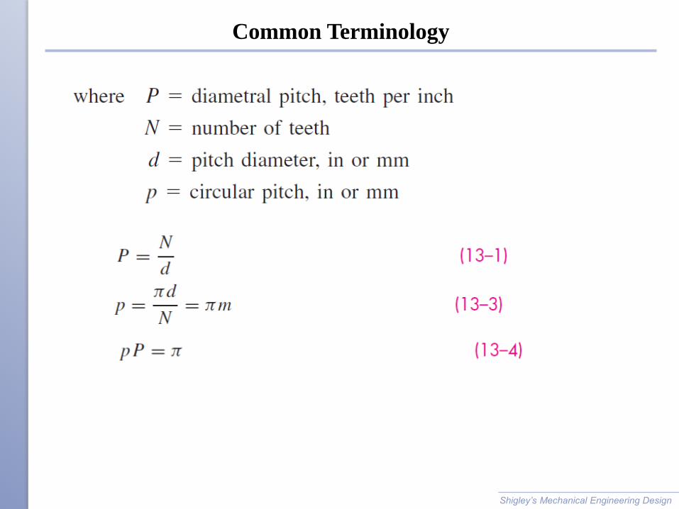
Common Terminology
Shigley’s Mechanical Engineering Design
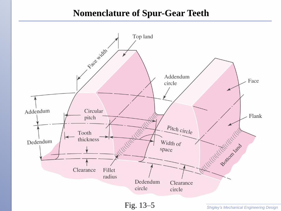
Nomenclature of Spur-Gear Teeth
Shigley’s Mechanical Engineering Design Fig. 13–5
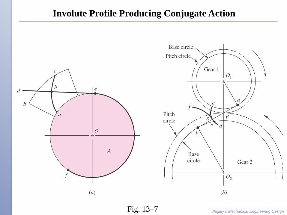
Involute Profile Producing Conjugate Action
Shigley’s Mechanical Engineering Design Fig. 13–7

Sequence of Gear Layout
• Pitch circles in contact
• Pressure line at desired pressure angle
• Base circles tangent to pressure line
• Involute profile from base circle
• Cap teeth at addendum circle at 1/P from pitch circle
• Root of teeth at dedendum circle at 1.25/P from pitch circle (clearance)
• Tooth spacing from circular pitch, p = p / P
Shigley’s Mechanical Engineering Design
Fig. 13–9
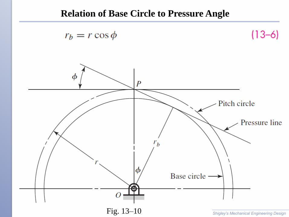
Relation of Base Circle to Pressure Angle
Shigley’s Mechanical Engineering Design Fig. 13–10
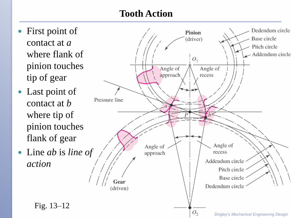
Tooth Action
First point of
contact at a
where flank of
pinion touches
tip of gear
Last point of
contact at b
where tip of
pinion touches
flank of gear
Line ab is line of
action
Shigley’s Mechanical Engineering Design
Fig. 13–12
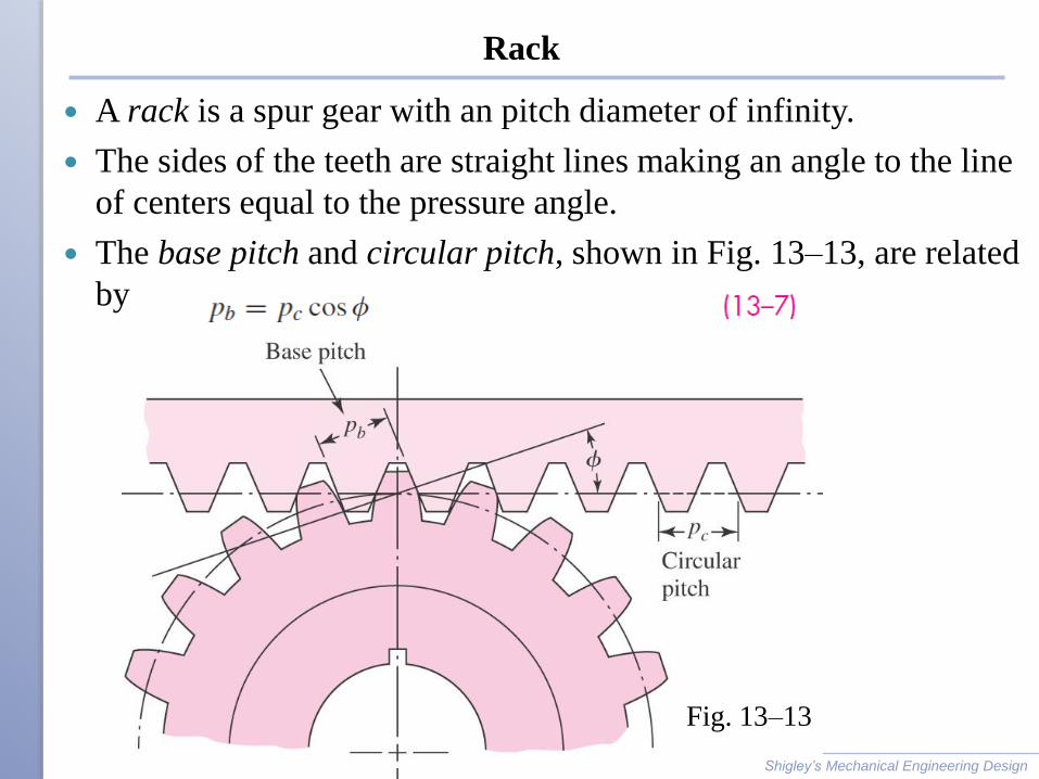
Rack
A rack is a spur gear with an pitch diameter of infinity.
The sides of the teeth are straight lines making an angle to the line
of centers equal to the pressure angle.
The base pitch and circular pitch, shown in Fig. 13–13, are related
by
Shigley’s Mechanical Engineering Design
Fig. 13–13
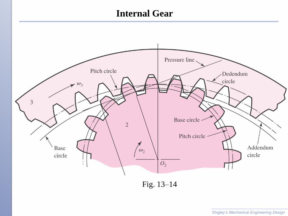
Internal Gear
Shigley’s Mechanical Engineering Design
Fig. 13–14
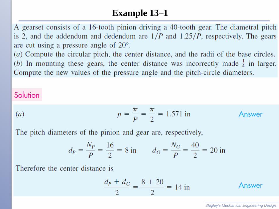
Example 13–1
Shigley’s Mechanical Engineering Design
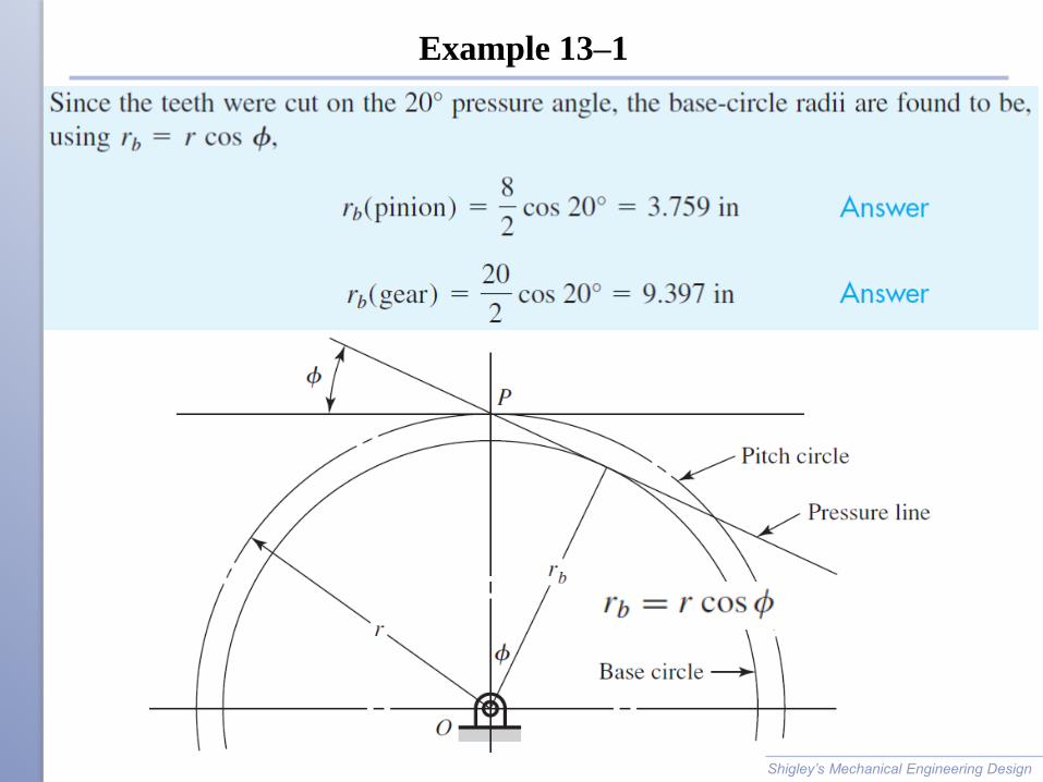
Example 13–1
Shigley’s Mechanical Engineering Design
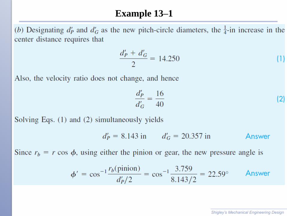
Example 13–1
Shigley’s Mechanical Engineering Design
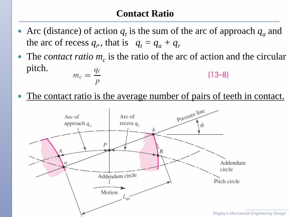
Contact Ratio
Arc (distance) of action qt is the sum of the arc of approach qa and
the arc of recess qr., that is qt = qa + qr
The contact ratio mc is the ratio of the arc of action and the circular
pitch.
The contact ratio is the average number of pairs of teeth in contact.
Shigley’s Mechanical Engineering Design
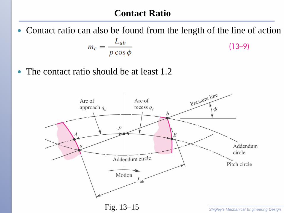
Contact Ratio
Contact ratio can also be found from the length of the line of action
The contact ratio should be at least 1.2
Shigley’s Mechanical Engineering Design Fig. 13–15
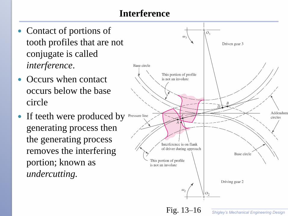
Interference
Contact of portions of
tooth profiles that are not
conjugate is called
interference.
Occurs when contact
occurs below the base
circle
If teeth were produced by
generating process then
the generating process
removes the interfering
portion; known as
undercutting.
Shigley’s Mechanical Engineering Design Fig. 13–16
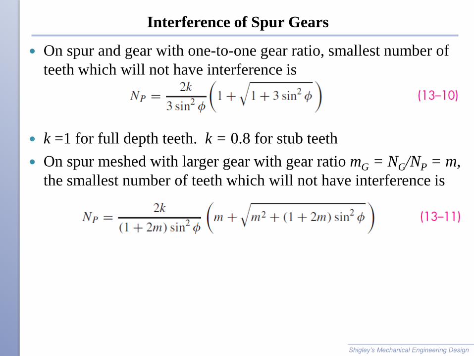
Interference of Spur Gears
On spur and gear with one-to-one gear ratio, smallest number of
teeth which will not have interference is
k =1 for full depth teeth. k = 0.8 for stub teeth
On spur meshed with larger gear with gear ratio mG = NG/NP = m,
the smallest number of teeth which will not have interference is
Shigley’s Mechanical Engineering Design
Interference of Spur Gears
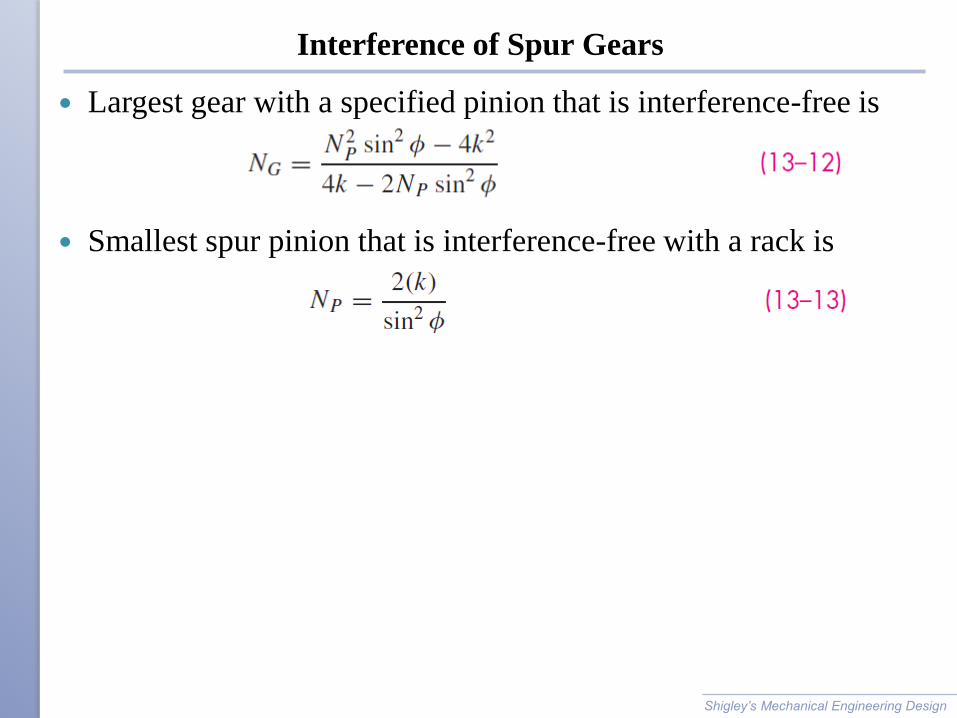
Largest gear with a specified pinion that is interference-free is
Smallest spur pinion that is interference-free with a rack is
Shigley’s Mechanical Engineering Design
Interference
Shigley’s Mechanical Engineering Design
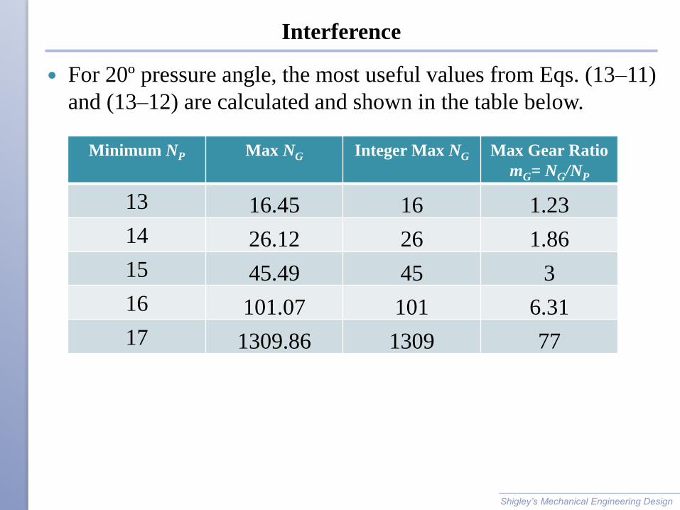
Minimum NP Max NG Integer Max NG Max Gear Ratio
mG= NG/NP
13 16.45 16 1.23
14 26.12 26 1.86
15 45.49 45 3
16 101.07 101 6.31
17 1309.86 1309 77
For 20º pressure angle, the most useful values from Eqs. (13–11)
and (13–12) are calculated and shown in the table below.
Interference
Shigley’s Mechanical Engineering Design
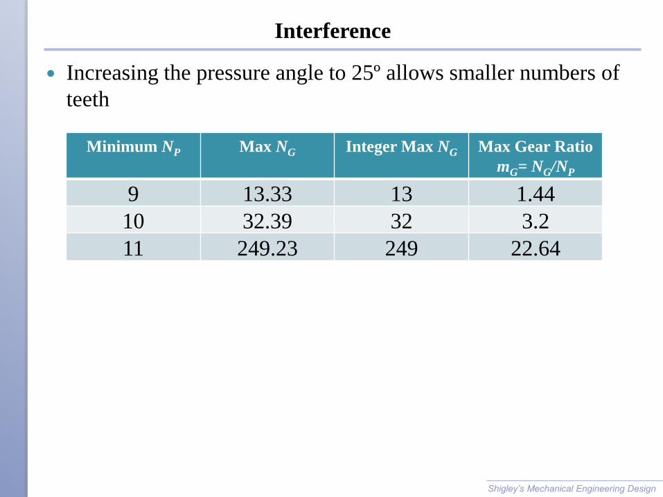
Minimum NP Max NG Integer Max NG Max Gear Ratio
mG= NG/NP
9 13.33 13 1.44
10 32.39 32 3.2
11 249.23 249 22.64
Increasing the pressure angle to 25º allows smaller numbers of
teeth
Interference
Interference can be eliminated by using more teeth on the pinion.
However, if tooth size (that is diametral pitch P) is to be
maintained, then an increase in teeth means an increase in
diameter, since P = N/d.
Interference can also be eliminated by using a larger pressure
angle. This results in a smaller base circle, so more of the tooth
profile is involute.
This is the primary reason for larger pressure angles.
Note that the disadvantage of a larger pressure angle is an increase
in radial force for the same amount of transmitted force.
Shigley’s Mechanical Engineering Design
Forming of Gear Teeth
Common ways of forming gear teeth
◦ Sand casting
◦ Shell molding
◦ Investment casting
◦ Permanent-mold casting
◦ Die casting
◦ Centrifugal casting
◦ Powder-metallurgy
◦ Extrusion
◦ Injection molding (for thermoplastics)
◦ Cold forming
Shigley’s Mechanical Engineering Design
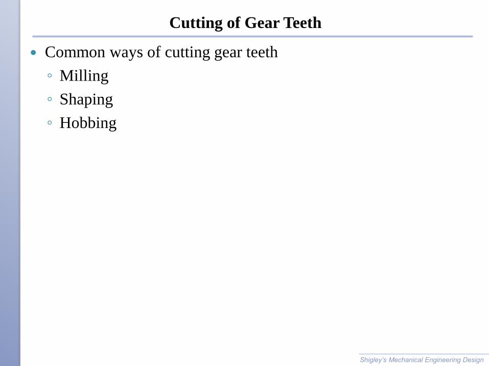
Cutting of Gear Teeth
Common ways of cutting gear teeth
◦ Milling
◦ Shaping
◦ Hobbing
Shigley’s Mechanical Engineering Design
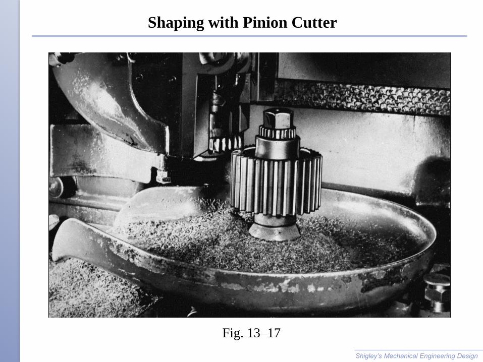
Shaping with Pinion Cutter
Shigley’s Mechanical Engineering Design
Fig. 13–17
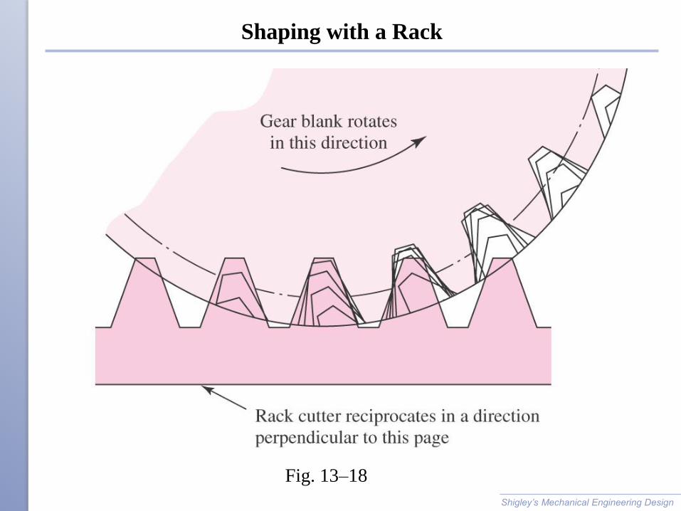
Shaping with a Rack
Shigley’s Mechanical Engineering Design
Fig. 13–18
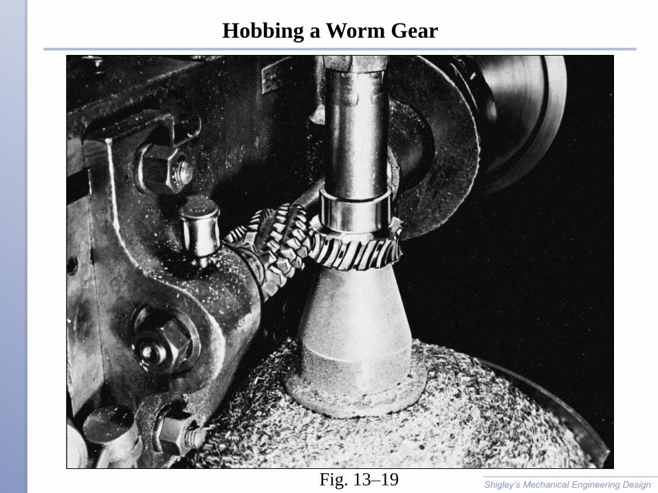
Hobbing a Worm Gear
Shigley’s Mechanical Engineering Design Fig. 13–19