Embed Size (px)
Citation preview

Mad
e to measure. P
ractical guide to electrical m
easurements in low
voltage switchb
oards
(a)
(b)V
t
V
t
(f)50 Hz
A
050
100
150
200250 500
A
050
100
150
200250 500
V
0
8060
40
20
Made to measure.Practical guide to electrical measurements in low voltage switchboards
2CS
C44
5012
D02
01 -
12/
2010
- 1
.500
- C
AL.
Contact us
ABB SACEUna divisione di ABB S.p.A.Apparecchi ModulariViale dell’Industria, 1820010 Vittuone (MI)Tel.: 02 9034 1Fax: 02 9034 7609
bol.it.abb.comwww.abb.com
The data and illustrations are not binding. We reserve the right to modify the contents of this document on the basis of technical development of the products,without prior notice.
Copyright 2010 ABB. All rights reserved.


Made to measure. Practical guide toelectrical measurements in low voltage switchboards
table of
contents
1 Electrical measurements
1.1 Whyisitimportanttomeasure?.......................................... 31.2 Applicationalcontexts.......................................................... 41.3 Problemsconnectedwithenergynetworks......................... 41.4 Reducingconsumption........................................................ 71.5 Tableofcharges.................................................................. 81.6 Absorptionpeaks................................................................ 81.7 Dividingconsumption.......................................................... 91.8 PowerFactorCorrectionandMaintenance.......................... 91.9 Remoteandhistoricalreadingofinformation....................... 9
2 Technical reference standards
2.1 IECstandards.................................................................... 102.2 MIDDirective..................................................................... 11
3 Measuring instruments
3.1 Analogueinstruments........................................................ 123.2 Digitalinstruments............................................................. 143.3 Measurementerrorsandaccuracyratings......................... 153.4 Comparisonbetweenthetwocategoriesofinstrument: advantagesandlimits........................................................ 18
4 Direct and indirect measurements: CTs, VTs, converters and accessories
4.1 Directmeasurements......................................................... 204.2 Indirectmeasurements...................................................... 204.3 Shuntsfordirectcurrent.................................................... 234.4 Convertersandaccessories.............................................. 23
5 Overview of ABB range
5.1 Analogueinstruments........................................................ 24 5.1.1 DINrailanalogueinstruments............................................ 24 5.1.2 Analogueinstrumentsonfrontofpanel.............................. 25 5.1.3 Advantages....................................................................... 275.2 Digitalinstruments............................................................. 28 5.2.1 DINraildigitalinstruments................................................. 29 5.2.2 Analogueinstrumentsonfrontofpanel.............................. 29 5.2.3DMTMEmultimeters.......................................................... 30 5.2.4MTMEandANRnetworkanalysers................................... 31 5.2.5Temperaturemeasuringunits............................................ 34 5.2.6Electronicenergymeters................................................... 355.3 Accessoriesformeasuringinstruments.............................. 36 5.3.1Serialcommunicationadapters.......................................... 36
5.3.2 Currenttransformers......................................................... 37 5.3.3Voltagetransformers......................................................... 38 5.3.4Shuntsfordirectcurrent.................................................... 38
6 The measurements
6.1 TRMSMeasurements........................................................ 40 6.1.1Linearloads....................................................................... 40 6.1.2Nonlinearloads................................................................. 40 6.1.3ProblemsconnectedwithTRMSmeasurements............... 416.2 HarmonicdistorsionandTHD............................................ 426.3 Cosfì(cosϕ)andpowerfactor(PF)...................................... 446.4 Practicaltipsforinstallingagood measuringsystem............................................................. 44
7 Digital communication
7.1 Communicationprotocols.................................................. 49 7.1.1 Thephysicallayer.............................................................. 49 7.1.2Theconnectionlayer......................................................... 52 7.1.3Theapplicationallayer....................................................... 52 7.1.4Compatibilitybetweenlevels.............................................. 537.2 Supervisionofelectricaldistributionplants......................... 537.3 TheModbusRS-485network............................................ 55 7.3.1Rulesforcorrectcabling.................................................... 55 7.3.2TheoperationoftheModbussystem................................. 57
8 Applicational examples of network analysers
8.1 Nominalvoltage(phase/neutral)andlinkedvoltage (phase/phase)astrueeffectiveTRMSvalue....................... 628.2 CurrentastrueeffectiveTRMSvalue onthethreephasesandonneutral................................... 628.3 Powerfactor(cosϕ)............................................................ 628.4 Activepower..................................................................... 638.5 Harmonicdistortionrate(HDR) upto31thharmonicdisplayedgraphically andasapercentagevalue................................................. 638.6 Harmonicdistortionupto31thharmonicdisplayed graphicallyandasapercentagevalue............................... 638.7 Activeenergyconsumedandgeneratedwithsubdivision ofthecountintototalcountersandaccordingtosettable timesofday....................................................................... 63
9 Annex
9.1 MeasurementsGlossary.................................................... 64
Madetomeasure.Practicalguidetoelectricalmeasurementsinlowvoltageswitchboards 1

2 Madetomeasure.Practicalguidetoelectricalmeasurementsinlowvoltageswitchboards
1 1Electric measurements
Measurement:ratiobetweenonequantityandanotherthatishomogenoustoit,whichisconventionallyaunit.Nevertheless,intheelectricalfielditisnotalwayseasytofindsamplestocompare,especiallyformeasurementsconductedoutsideequippedlaboratories.Inpractice,calibratedinstrumentsarethereforeusedthatdonotcomparetheelectri-cal quantity under examination with an electrical sample but with another type ofquantity(forexample,inanalogueinstruments,theforceexertedbyaspring).Thegeneraldefinitionofthemeasuringconceptmakesitimportanttodefinetheunitsofmeasurement,whichmustbeinvariableandingeneralreproducible.ThecorrectunitsofmeasurementsthathavetobeusedarethoseindicatedbytheSI(SystèmeInternational);Table1.1showsthefundamental(orbasic)unitsofmeas-urementoftheSI.
QuantityUnit
Standards Symbol
Length metre m
Mass kilogram kg
Time second s
Current ampere A
Thermodynamic kelvin K
Quantityofsubstance mole mol
Lightintensity candle cdTable 1.1 Basic SI unit

Madetomeasure.Practicalguidetoelectricalmeasurementsinlowvoltageswitchboards 3
1
ElE
CT
riC
ME
As
ur
EM
En
Ts
Table1.2showstheelectricandmagneticquantitiesthataremostoftenencounteredandwhichneedtobemeasured.
QuantitySI Unit Dimensional
expressionname symbol
-Electriccurrent ampere I A
-Quantityofelectricity(load) coulomb C s·A
–Electricpotential•potentialdiff.•electromotiveforce•voltage
volt V m2·kg·s-3·A-1
-Electriccapacity farad F m-2·kg-1·s4·A2
-Permittivity faradpermetre F/m m-3·kg-1·s4·A2
-Resistance•impedance
ohm Ω m2·kg·s-3·A-2
-Resistivity ohmpermetre Ω·m m3·kg·s-3·A-2
-Conductance siemens S m-2·kg-1·s3·A2
-Conductivity siemenspermetre S/m m-3·kg-1·s3·A2
-Inductance henry H m2·kg·s-2·A-2
-Electricfield voltpermetre V/m m·kg·s-3·A-1
-Loaddensity coulombpermetre2 C/m2 m-2·s·A
-Currentdensity amperepermetre2 A/m2 m-2·A
-Frequency hertz Hz s-1
-Inductionflow weber Wb m2·kg·s-2·A-1
-Magneticinduction tesla T kg·s-2·A-1
-Magneticfield amperepermetre A/m m-1·A
-Magneticpotential weberpermetre Wb/m m·kg·s-2·A-1
-Dielectricconstant faradpermetre ε m-1·kg-1·s4·A
-Magneticpermeability henrypermetre μ m·kg·s-2·A-2
-Power watt W m2·kg·s-3
-Energy wattpersecond J m2·kg·s-2
1.1
Why is it important to measure?Asarticle2ofEuropeanDirective374of25July1985statesthat'alsoelectricity'isa'product',equatingitwithanyothertypeof'movablegoods',thefirst,immediateansweris:tobeabletomarkettheproductelctricity.Usingamoresophisticatedargument,evenifitislimitedtothemanagementaspectsofapowerplant (thus ignoringall thetechnicalandscientificquestions), there isaclearneed in today'smarket tocontainandreducecostsandensurecontinuityofservice.Ithasthusbecomevitaltothoroughlyfamiliariseoneselfwiththeoperationofanelectricplantinordertobeabletooptimise:consumption,loadcurves,harmonicinterference,voltagedisturbances,etc,i.e.alltheelementsthatcontributetoincreaseefficiency,improvingcompetetitivity,and,animportantfactortoday,reducingharmfulemissionsintheenvironment.Lastly,stillfromthemanagementpointofview,measuringandmonitoringelectricalquantitiesenablefaultpreventiontobeoptimisedandmaintenancetobescheduledowingtoearlyidentificationofproblemsthatresultsingreaterprotectionnotonlyoftheplantsbutalsooftheobjectsconnectedtothem.
Table 1.2 Main electric and magnetic quantities
continues1

4 Madetomeasure.Practicalguidetoelectricalmeasurementsinlowvoltageswitchboards
1
ElE
CT
riC
ME
As
ur
EM
En
Ts
1.2
Applicational contextsAnefficientsystemofmeasuringandmonitoringelectricalquantitiesisimportantforensuringthesuccessofallinitiativesthatrequire:-energycoststobecontained;-qualityenergysupplies;-continuityofserviceoftheplants.Specifically,achievingtheaboveobjectivesrequirestheactivitiestobeimplementedthataresetoutintheflowchartinFig.1.1.
Functions:-submeteringof
consumptionanddividingcosts
-monitoringloadpatterns
-managingpeaks-improvingpower-
factorcorrection
Functions:-analysingharmonics-detectingovervoltages,
voltagevariations,andvoltagegaps
-detectingdischargesfromsteeptransients
-conformityofsupplytoEN50160
Functions:-controlofplantin
realtime-remotecontrol-managingalarms
anddividingcosts-preventive
maintenanceandmaintenanceintheeventofafault
Functions/objectives of electric measurements
Reducing energy costs
Energy qualityContinuity of service
ABBmeasuringinstrumentsareanalogueanddigitalnetworkanalysersandenergymetersthatoptimisetheabovefunctionsinthemostvariedapplicationalcontexts:-residentialandcommercialbuildings-industries-shoppingcentres-garages-collegesandcampuses-tradefairsites,exhibitionvenues-touristports-hotelsandcampsitesAlltheABBinstruments,bothoftheDINrailandpanelfronttype,aredistinguishedbythesuperiorityandexcellenceoftheirproperties,andlastbutnotleast,theyen-ablelowvoltagepowerpanelsandcabinetscabledintothepowercentrestobeen-hancedandtheiraestheticappealtobeapproved.
1.3
Problems connected with energy networksInordertodefinethefeaturesofthepowersupplyatthedeliverypoints,adistinctionmustbemadebetweennormalandemergencyoperationofanelectricalsystem.Anelectricalsystemisrunningnormallywhenitisabletomeettheloadsupply,elimi-natefaultsandresumeoperationwithordinarymeansandproceduresiftherearenoexceptionalconditionsduetoexternalinfluencesorsignificantcriticalsituations.Emergencyoperationoccurswhen,owingtoinsufficientgenerationcapacityorbe-causeofsituationshavingagraveimpactonthesystem,orowingtoeventsthatarebeyondthecontrolofthepowerprovider(deliberatedestruction,disasters,strikes,acts of the public authorities, etc), it becomes necessary to interrupt or limit the
Fig. 1.1: Functions and objectives of electric measurements

Madetomeasure.Practicalguidetoelectricalmeasurementsinlowvoltageswitchboards 5
1
ElE
CT
riC
ME
As
ur
EM
En
Ts
service.Thethree-phasevoltagesuppliedtothedeliverypointsbythepublicdistributionsys-temduringnormaloperatingconditionshasthefollowingfeatures(seealsoTable1.3):-frequency-amplitude-waveform-symmetryofthethree-phasevoltagesystem.Thedistributingbodycanalso imposelowvoltagesignalsonthevoltagethathavetheaimoftransmittinginformationonoperation.Thesefeaturesaresubjecttovariationduringnormaloperationoftheelectricalsys-temduetoloadfluctuations,disturbancesgeneratedbycertaintypesofuserequip-mentorplantsandtheoccurrenceoffaults,whicharemostlyduetoexternaleventsthatmaycausetemporaryinterruptionstothesupply.Asaresult, thesecharacteristicsarechangeableovertime, if referredtoaspecificdeliverypoint;theyarechangeableinspaceifatagivenmomentallthedeliverypointsinadistributionnetworkareconsidered.Consequently,inbothcases,theymustbedescribedinstatisticalterms;Fig.1.2showsthedifferenttypesofvariationofvoltageamplitudeduetotransistorandpulsephenomena.Table1.4liststhemaindisturbingdevices,i.e.machinesandequipmentoftheuserthatmayintroduceelectromagneticdisturbances.Theyarelistedbytypeofapplica-tiontoshowhowthesametypeofdevicemaysimultaneouslygenerateseveraldis-turbances.Forexample,a resistanceweldingunitmaygenerate:dissymmetryandunbalance,voltagefluctuation,voltagevariations,respectivelyindicatedinthecolumnsontherightofTable1.4bythelettersSQ,VF,VV.
CharacteristicPhenomenon
Type Description
Frequency Variation %deviationfromnominalvalue
Amplitude Slowvariations %deviationfromnominalvaluewithdurationofvariation>10s
Rapidvariations %deviationfromnominalvaluewithdurationofvariation<10s
Overvoltages Risesinvoltagemeasuredasinstantaneousabsolutevalueoraspercentageofnominalvalue
Holes Partialdecreasesbelow90%ofratedvoltageanddurationcomprisedbetween10msand60s
Shortinterruptions Novoltagefor≤180s
Longinterruptions Novoltagefor>180s
Waveform Harmonics Theyaresinusoidalvoltagesorcurrentswithafrequencyequaltoacompletemultipleofthebasicfrequency,thepresenceofwhichcausesadistortiontothewaveformofthesupplyvoltage
Interharmonics Theyarevoltagesorcurrentsthatmaybesinglesinusoidalcomponentswithafrequencythatisnotanentiremultipleofthebasicfrequencyormaybeanextendedspectrumofsinusoidalcomponents
Symmetryofthethree-phasesystem
Dissymmetry Inconsistentamplitudeand/oranglebetweenthemeasuredphasesasadegreeofdissymmetry Table 1.3 Voltage
characteristics
continues 1.3

6 Madetomeasure.Practicalguidetoelectricalmeasurementsinlowvoltageswitchboards
1
ElE
CT
riC
ME
As
ur
EM
En
Ts
Fig. 1.2: Schematisation oftypes of variation of
voltage amplitude
Key:SQ = dissymmetries and unbalanceVF= voltage fluctuationsVV = voltage variationsAR = harmonicsSF = spurious frequenciesRE = radioemission(1) if single-phase(2) at insertion, when power is not low
compared with the power of the short-circuit power of the network
(3) if remote control
Key:a) Voltage gaps:
durationfrom10msto60s,ifthevoltageiscompletelycancelledtheinterruptionsareknownasshortinterruptions
b) Non pulsed overvoltages:theoppositeofvoltagegaps
c) Slow variations:amplitudevariationsinrelationtothenominalvaluewithduration>10s
d) Pulsed voltages of long duration: durationcomprisedbetween0.1msandsomemsoriginatingfromfaultsormanoeuvres
e) Pulsed voltages of medium duration: durationcomprisedbetween1and100μsofatmosphericoriginorfromactionofswitchesorcircuitbreakersorfromtrippedfuses
f) Pulsed voltages of short duration: duration<1μsoriginatingfromactionsofswitchesorcircuitbreakersinspecialcases
g) Communication transients: originatingfromconverterdevicesandrectifiers
Table 1.4 Disturbing devices
Devices PowerDisturbances generated
SQ VF VV AR SF RE
Resistanceheating 1-40kW (1) (2) (3)
Domesticovens-microwaveovens-infraredovens 1-2kW
(1)(1)
••
• •
Industrialkilns-induction-HF-UHF-plasma-arc
10-2,000kW10-600kW10-100kWsomeMVA1-100MVA • •
••••
•••
•
•••
•
•••
Weldingmachines-resistance-arc
0.1-2MW1-300kW
• ••
•• (3)
Motors-asynchronous(e.g.compressors)-variablespeed
<10MVA
-20MVA
•
•
•
•
• •
•
Transformers <100MVA • •
Converters-ac/dc-ac/acandcycleconverters
<10MW<30MW
••
•• •
Electroerosion 10-30kW •
Dischargelamps •
Televisions • •
Radiology • •
continues 1.3
(a)
(b)V
t
V
t
VM
V
t
(c)
(d)
V
t
(e)
50 Hz
V
t
(g)
V
t
(f)50 Hz

Madetomeasure.Practicalguidetoelectricalmeasurementsinlowvoltageswitchboards 7
1
ElE
CT
riC
ME
As
ur
EM
En
Ts
Fig. 1.3: How to reduce consumption
Thesamedevicemayalsogenerateseveraldifferenttypesofdisturbanceatthesametime.Emissionlevelsforthevariousdisturbancesarecalculatedinthefollowingmanner:-theemissionlevelofthesingledevicesiscalculated;-thetotalemission leveloftheuser iscalculatedasacompositionoftheemission
levelsofthesingledevices;-thetotalemissionleveloftheuseriscomparedwiththepermittedemissionlevel;
thisemissionlevelisgenerallydefinedbythedistributoronthebasisofcriteriathatensurecontrolofthecompatibilitylevels.
Theemissionlevelsaregenerallymeasuredatthe'commoncouplingpoints'thataredeemedtobeofparticularinterest:pointofcommoncouplingwiththenationalgrid(PCC)andinternalpointsofcommoncouplingwiththeuserdistributionnetwork(PIC).Thedisturbancesthatoccurmostfrequentlyandthathavetobeassessedandcon-tainedare:-harmonics;-rapidvoltagevariations;-flickers.Thelatterarevoltagefluctuationsthathaveamodulationfrequencybetween0.5and35Hzandgiverisetothephenomenonofflicker,i.e.thesensationoffluctuationsintheintensityofthelightofthelamps.
1.4
Reducing consumptionTherisingcostofelectricenergyisasignificantproblemandisoneoftheparametersthatisincreasinglycomingunderscrutinyinordertocontainthegeneralcostsofabusiness.Statisticsdrawnupbothnationallyandinternationallyshowthateverysinglecompanycanreduceitsenergybillfrom10%to30%.Thissavingspercentagevariesaccordingtotheevaluationoftheconsumptionmadeduringthepowerplantdesignphaseandevenmoreforolderplantsintermsoftheconsumptionanalysisandtherelativesolutionsadoptedtomanageconsumption.ThestepsrequiredtoachieveagoodresultaresummarisedinFig.1.3.
Reducing consumption
Contract analysisConsumption
analysisTechnical
interventions
continues 1.3

8 Madetomeasure.Practicalguidetoelectricalmeasurementsinlowvoltageswitchboards
1
ElE
CT
riC
ME
As
ur
EM
En
Ts
1.5
Table of chargesTheanalysisofthesupplycontractforelectricpowerrevealsaseriesofusefulpiecesofinformation:-thepowerused,i.e.themaximumvalueofavailablepowerthat is limitedormust
notbeexceededinordernottoincurpenalties;-thetableofchargesthatcanbefixedormayvaryaccordingtothetimeofday;-thepeakorexcessivepowerthatexceedsthecontractuallyagreedsupply.
Thecommittedpower is themaximumusablevaluethat, forcontracts for levelsofpowerthatarenotparticularlyhigh(generallyupto35kW)ismanagedbyacurrentlimiterthat interruptstheenergysupplywhenconsumptionexceedsthecommittedvalue.Thepowercommitment issetduringthedesignstageonthebasisoftheeffectivepowerrequiredforsimultaneouslyrunningloadsduringpeakconsumptonperiods.EachkWcommittedhasa fixedcostand it is thereforeadvisable toassessactualneedstoavoidpayingforunnecessarypower.Thecontractmustbesignedafteranassessmentofthemostappropriateusernet-work architecture, taking into account the following of the most importantparameters:-numberofconnectionpoints;-lowormedium-voltagedeliveryorseverallowvoltagedeliverypoints;-creatinganemergencyplant;-makingconsumptionforecastsonthebasisoftheactualconsumptionandnoton
thesumofthenominalpoweroftheloads(todefineavailablepower).During the course of the supply contract the user should periodically examine theconsumptionstated in theelectricitybillsandmakeanalyses/recordswithsuitableinstruments;hencetheimportanceofmeasuringandmonitoringenergyconsumptionovertime.
1.6
Absorption peaksForpowerabove37.5kWthepowerproviderusesenergymetersthatmeasureab-sorptionovertime,recordingaverageconsumptionevery15minutes(Fig.1.4).
0 15 mi
Area proportionalto average value
Instantaneous power Integrated value
tip-measuring device
n
100 kW
0 15 min
200 kW
If,forexample,thecontractisfor100kW,thepeakvalueisdeemedtobewithinthecontractualvalueiftheaveragevalueofmaximumconsumptionis100kWin15min-utes,whichmaybetheequivalentofaverageconsumptionof200kWin7.5minuteswith0kWconsumptioninthefollowing7.5minutes.Inordertoavoidpenalties,itisimportanttocontrolandmanageabsorptionpeakssoastoneverexceedtheavailablepoweraverage.Acorrectanalysisofconsumptionenablesthesuitabilityofthetypeofcontracttobecheckedagainsttheuser'suseparameters,thusslashingcompanycostsandavoid-ingahighpriceadjustmentattheendoftheyear;forexamplerecordingenergycon-sumptionatdifferenttimesofdayenablesallthepowerconsumptionofthedayormonthtobemonitored,thusprovidingacompletepictureoftheenergysituation.
Fig. 1.4: Graphic representation of average consumption

Madetomeasure.Practicalguidetoelectricalmeasurementsinlowvoltageswitchboards 9
1
ElE
CT
riC
ME
As
ur
EM
En
Ts
1.7
Dividing consumptionIf it isfundamentaltoknowconsumptiontooptimiseenergysaving,it isjustasim-portanttousetheenergyavailableunderthecontractrationallyinordertoavoidin-terruptionstothesupplyandpenaltycharges.Inresidentialortertiary-sectorenvironments,wheretheavailablepowerislimitedandloadneedschangecontinuouslyovertheday,itisimportanttoknowmomentarycon-sumptionand tobeable todisconnect less important installations if themaximumpowerlevelisreached.Forexample,ifinadomesticenvironmentseveralmachinesareworkingsuchas:awashingmachine,dishwasher,vacuumcleaner,etcthatexceedthecontractualpower,thelimiterintheelectricitymeteroftheproviderinterruptsthesupplyanddisconnectspower to theentire system. In simplecases suchas thisonea loadmanagementswitchmaysuffice(forexampletheLSS1/2switch),whilstinmorecomplexenviron-mentssuchasindustryandthetertiarysector,itispossibletouseABBenergymetersoftheODINsingleandDELTAsinglesingle-phasemeters,andODINandDELTAplusthree-phasemeters(seechapter5below)tomonitorcontinuouslyconsumptionandmakecontingencyplans forcases inwhich themaximumsetvalue is reached (forexamplebydisconnectingonlytheinstallationsthatareconsideredtobelessimpor-tant,maintainingthesupplytothemaininstallations).
1.8
Power Factor Correction and MaintenanceThepowerfactororcosϕ (whichisthephaseanglebetweenthephasorsofthevoltageofthecurrent),mustbemaintainedatavaluethatisasnearaspossibleto1,toavoidunnecessary inductive currents that overload the line of the supplier company. As isknown,theuserdevices,whichmostlyhaveinductiveloads(forexample):motorsandtransformers),needmagnetisingcurrenttooperatethatdoesnotproduceworkbutloadsthelines,reducingtheircapacity.Forthisreason,thesuppliersofelectricpowerapplyapenaltywhenthepowerfactorcosϕislessthan0.9.Itisthusimportanttomeasurethepowerfactorandifitdoesnotfallwithinthecontrac-tuallimits,power-factorcorrectingcapacitorsmustbefittedtotheout-of-phaselines.Measuringandrecordingconsumptionthusbecomesanimportantindicatorforschedul-ingmaintenance, inparticular in industrialenvironments,because identifying themostused linesanddevicesenablesthe interventionstobecontrolledandestablished inascheduledpreventivemaintenanceprogramme.
1.9
Remote and historical reading of informationInordertoconductathoroughanalysisofelectricparametersandofevents,itisim-portant for themeasuring instruments tohaveasystem forstoringmeasureddataandtobeabletotransferremotelysuchdatainordertocompareandanalysethem.Remotereadingandstoringinformationareusedespeciallyinplantswithagreatex-tentandinthepresenceofheavyloads,suchas,forexample,inthelargechainstoresandinindustry.

10 Madetomeasure.Practicalguidetoelectricalmeasurementsinlowvoltageswitchboards
2Technical reference standards
Inanytechnicalenvironmentandinparticularintheelectricalsector,inordertomake'workmanlike'devices,allrelevantlegalandtechnicalstandardsmustbecompliedwith.Knowledge of standards and distinguishing between legal standards and technicalstandardsisthusthebasisforacorrectapproachtomeasuring-instrumentquestionsthatinvolvesnotonlytechnicalaspectsrelatingtoaccuracyandsafetybutalsotaxandaccountingmatters.Legalstandardsareallthosegoverningthebehaviourofpartiessubjecttotheauthorityofthestate,includingtheEuropeandirectivesthatarenormallyenactedinnationalleg-islationthroughlegislativedecrees.Technicalstandardsarealltheprescriptionsonthebasisofwhichthemachines,de-vices,materialsandplantshavetobedesigned,builtandtestedtoensuretheiroper-atingefficiencyandsafety.Thetechnicalstandardssetbynationalandinternationalbodies(CEI,CENELEC,IEC)havebeendrawnupinaverydetailedmannerandcanhavelegalsignificancewhenthisisassignedtothembyalegislativemeasure.
2.1
IEC standardsThreecommitteesarespecificallyresponsibleformeasuringinstrumentation.-TC85"Measuringequipmentforelectricalandelectromagneticquantities"-TC66"Safetyofmeasuring,controlandlaboratoryinstruments"-TC13"Electricalenergymeasurement,tariffandloadcontrol".Thefirstcommitteedrawsupandpublishesthereferencestandardsforalltheinstru-ments(voltmeters,ammeters,wattmeters,etc)ofbothanalogueanddigitaltypeandprovidestheprescriptionsfortheinstrumentsandthesampleequipment(batteries,resistors,recordinginstruments,etc).Committee85isalsoresponsibleforaseriesofstandards,allofwhichareEuropeaninorigin(fromIECEN61557-1toIECEN61557-10),dedicatedtoelectricalsafetyinlowvoltagedistributionsystems.Thesestandardsalsocontainsomesafetyprescrip-tionsandthefunctionalfeaturesrequiredfortheinstrumentsforthetests,measure-mentsandcontrolsoflowvoltageelectricplantssuchas,forexample:earthresist-ancemeasuringinstruments,instrumentsformeasuringimpedanceoffaultloop,in-struments for testing continuity of protection conductors, insulation measuringinstruments,etc.Thesearethereforeparticularlyimportantstandardsfordefiningtherequiredcharac-teristicsofthemeasuringinstrumentstobeusedforthetestsprescribedbystandardIEC60364thatgovernslowvoltageelectricplants.Committee66dealswiththesafetyprescriptionsforelectricalmeasuringdevicesthatmustbemetbythemanufacturertoensurethesafetyoftheoperator.

2
TE
CH
niC
Al r
EFE
rE
nC
E s
TAn
DA
rD
s
Madetomeasure.Practicalguidetoelectricalmeasurementsinlowvoltageswitchboards 11
Lastly,Committee13isentirelydedicatedtopublishingthestandardsgoverningac-tiveenergyandreactiveenergymeasurementsandtherelativedevices:meters,inte-gratedunits,devicesofdifferenttypes.Inthisconnectionthefollowingstandardshaveparticular importance for the purposes of tests on energy meters: EN 50470-1,EN50470-2,EN50470-3,whichsetthetestprescriptionsbothforelectromechanicalactiveenergymetersandforstaticmeters.Fig.2.1summarisesthestandardstowhichmeasuringinstrumentationissubject.
Reference Standards for measuring instruments
Electricalenergymeasurement,tariffandloadcontrol
TC13
Safetyofmeasuring,controlandlaboratoryinstruments
TC66
Measuringequipmentforelectricalandelectromagneticquantities
TC85
2.2
MID DirectiveEuropeanDirective2004/22/ECof31March2004introducedaCommunityframe-worklawgoverningdevicesandsystemswithmeasuringfunctionsrelatingtocom-monconsumergoods:water,gas,fluidsingeneraland,inparticular,“active electric energy meters and measuring transformers”,whichareidentifiedinthedirectivebyMI-003.Thedirectivestates that themeasuring instrumentmustconform to 'the particular requirements which are applicable to the instruments in question';fortheactiveelec-tric energymeters, the annexdefines specific requirements in termsof: accuracy,operating conditions, maximum tolerated errors, procedures for ascertainingconformity.Thedirectiveappliestoallelectricenergymeters,whethertheybelongtotheutilitycompanyortoprivateindividuals,thatareinstalledforanyreasoninplantsformeas-uringand/ormeteringelectricenergy;itisalsospecifiedthatthemeterscanbeusedincombinationwithexternaltransformers.Thesignificanceofthedirectiveisconsiderable,notonlybecauseitproposeselimi-natingallunreliablemeasuring instruments thathavenotbeenconstructed incon-formity to theproductstandardandsometimesdonotevenhaveCEmarking,butalsobecauseitenablesinstrumentationtobeused(providedthatitconformstothedirective)alsotometerenergyfortaxpurposes.
Fig. 2.1: Reference Standards for measuring instruments
continues 2.1

12 Madetomeasure.Practicalguidetoelectricalmeasurementsinlowvoltageswitchboards
3Measuring instruments
Forthelastfewdecadesbothanalogueanddigitalmeasuringinstrumentshaveex-istedalongsideoneanother.Theformeraredevicesinwhichtheinformationisassociatedwithphysicalquantitiesthatarecontinuouslyvariablewhereasindigitalinstruments(thatemergedlaterinthe1970sand1980swiththearrivalofelectronicsandIT)thequantitieshavediscretevalues(asintheword'digit').These instrumentsconsistofanA/D transducer-convertersystem for transforminganynonelectricinputquantityintoanoutletanalogueelectricquantity(generallyvolt-age)andsubsequentlyconvertingintodigitalform,andofacountersystemforpro-vidinginformationonthenumberofpulses.
3.1
Analogue instrumentsIn Fig. 3.1 a block diagram shows the initial configuration of an analogueinstrument.
Quantities to be measured
Drive torque Deflection angle Reading
Electromechanical converter
Force or torque meter
Angle meter
Theseinstrumentsexploitphenomenaforwhichtheinteractionofelectricormagneticquan-titiesgivesrisetomechanicalforceortorque.Theseinstrumentsconsistofamovablepartthathasaninitialrestposition,onwhichadrivingtorqueactsinfunctionoftheelectricormagneticquantitiesonwhichtheassociatedphenomenondepends.Thedrivingtorqueisopposedbyrestoring,normallyelastic,torque,which,dependingonthemovement,tendstoreturnthemovableparttotheinitialpositionwhentheactionpro-ducedbythedrivingtorqueceases.Fromthebalanceofthetwotorquesanangulardeviationisobtainedthatisproportionaltothequantitytobemeasured.Anindexfixedtothemovablepartrotatesalongascale.Ingeneral,themanufacturerplacesonthedialoftheinstrumentcertainconventionalsymbolsthatcharacterisenotonlytheunitofmeasurementbutalsotheoperatingprinciple,theconnectionnetwork(directoralternat-ing), theaccuracyrating,operatingposition(horizontal,vertical)andsafetyprescriptions(testvoltage).TheconventionalsymbolsthataregenerallyusedaresummarisedinTables3.1.and3.2.
Fig. 3.1: Block diagram of an electromechanical analogue instrument

3
ME
As
ur
ing
ins
Tr
uM
En
Ts
Madetomeasure.Practicalguidetoelectricalmeasurementsinlowvoltageswitchboards 13
Table 3.1 Identification of the instruments and symbols shown on the dial
Table 3.2 Identification of the instruments and symbols of the operating principle
Circuits in which it can be inserted
Circuit Symbol Circuit Symbol
Directcurrent Three-phasealternatingcurrentwithacurrentcircuitandavoltagecircuit
Alternatingcurrent Three-phasealternatingcurrentwithtwocurrentcircuitsandtwovoltagecircuits
Directandalternatingcurrent Three-phasealternatingcurrentwiththreecurrentcircuitsandthreevoltagecircuits
Arrangement of the instrument
Arrangement Symbol Arrangement Symbol
Instrumenttobeusedwithverticaldial
Instrumenttobeusedwithtilteddial
Instrumenttobeusedwithhorizontaldial
Angleoftilt(optional)
Test Voltage
Voltage Symbol Voltage Symbol
Testvoltage500V Testvoltage5,000V
Testvoltage2,000V Instrumentexemptfromvoltagetest
Instrument Symbol Instrument Symbol
Fixedmagnetandmovingcoil Fixedmagnetandmovingcoilasratiomeasuringdevice
Movableiron Movableironasratiomeasuringdeviceorasdifferentialinstrument
Electrodynamic Electrodynamicasratiomeasuringdevice
Electrodynamicwithiron Electrodynamicwithironasratiomeasuringdevice
Induction Inductionasratiomeasuringdeviceorasdifferentialinstrument
Hot-wirethermaloverloadfuse Bi-metalbladethermaloverloadfuse
Electrostatic Vibratingblades
Movablethermocouplereel Movablereelwithrectifier
continues 3.1

3
ME
As
ur
ing
ins
Tr
uM
En
Ts
14 Madetomeasure.Practicalguidetoelectricalmeasurementsinlowvoltageswitchboards
3.2
Digital instrumentsTheoperatingprincipleofdigitalinstrumentsisbasedonanalogue-digitalconversiontechniques;decodinganddisplaydevicesarealwaysassociatedwiththem,asareveryoftensamplefrequencyoscillatorsanddecimalcountcircuits.TheblockdiagramisshowninFig.3.2.
Decoding and display
AttenuatorConverter
ConverterA/D
Controller
Thedigitalinstrumentsareessentiallyvoltmetersfordirectcurrents;nevertheless,us-ingusualconversionsystemsfromVACtoVDC(especiallythermocoupleconversionsystems)andintroducingdirect-currentsources,theycanbecomeuniversal instru-ments for also measuring high-frequency voltage up to a few hundred kHz andresistences.If thesemeasuring instrumentsare inplace theycanbeused tostoreandsubse-quentlycallupmeasuringvalues,andprocessthemandcontrolthemremotely,astheycanbeinterfacedwithmicroprocessorsystemsuntilautomaticmeasuringstruc-turesofgreatfunctionalversatilityareobtained.Twoparticularaspectsmustbeborne inmindwhenconstructingandusingdigitalinstrumentsinordernottocompromiseoperationandsafety:-electromagneticinference;-earthsockets.Themanufactureroftheinstrumentprotectsitdirectlyagainstelectromagneticinter-ferencebyprovidingtheinstrumentwithanelectrostaticscreen(anonferrousmag-neticmetal)thatisalsoeffectiveagainsthigh-frequencyelectromagneticfields.Thisscreencanbeconnectedtooneofthemeasuringterminalsoritcanconstituteathirdterminalinitsownright.Inthefirstcaseso-called'unbalanced'measurementsareobtainedasoneofthetwoterminalshastobeconnectedtothemeasurementearth,sothatonly twovoltagemeasurementsarepossiblethatrefertotheearthpotential.Ontheotherhand,ininstrumentswiththreeterminals,twoarededicatedtomeasur-ingandonethatisdedicatedtoshieldingisearthed.Inthiscasepotentialdifferencescanbemeasuredalsobetweenthetwopoints thatarebothoutsideearthandthetypeofmeasurementisknownas'balanced'.Earthconnectionsaredefinedasapointthepotentialofwhichremainsconstantandwhichisassumedtobeareferencepotential;thisisobtainedthroughanearthcon-nectionwithverylowimpedance.Inelectronic/digitalinstrumentsitmaybenecessarytohaveseveralreferencepointstowhichdistinctpartsofthecircuitsoftheinstrumentbelong;thesepointsareknownasmassconnectionsandareohmicallyisolatedfromoneanother(thecapacitivecou-plingmustalsobeminimised).ThesymbolsthataremostcommonlyusedforearthandmassconnectionsaresetoutinFig.3.3.
Fig. 3.2: General configuration of a digital instrument
Fig. 3.3: Symbols most commonly used for earth (a) and mass (b, c)
connections

3
ME
As
ur
ing
ins
Tr
uM
En
Ts
Madetomeasure.Practicalguidetoelectricalmeasurementsinlowvoltageswitchboards 15
3.3
Measurement errors and accuracy ratingsNomeasurementcanbeconsideredexact.Thelimitsmustthereforebeestablishedeachtimewithinwhichthevalueofthemeasuredquantityfalls,thusdefiningthemar-ginoferrorofthemeasurement.Errorsmayariseinameasuringoperationformanyreasonsandhavevariousorigins.Apartfromtheerrorsduetomajormistakes(e.g.fittinganinstrumentincorrectly),itispossibletodividethetypesoferrorintotwocategories:systematicandaccidental,asexplainedbetterintheblockdiagraminFig.3.4.
Fig. 3.4: The main causes of error in electric measurements(1)Parallaxandappreciationerrorsaretypicalonlyofanalogueinstruments
Causes of error
Theydonotdependontheoperator;theydependontheequipmentandonthe
measuringprocess
Systematic
Theydependontheinstrument
class
Instrumental
Theyareduetocurrentabsorptionbytheinstruments
andtovoltagedrops
Loss
Theyoccurwhenthescaleindexisnotreadperpendicularlytothe
scale
Parallax (1)
Theyarisefromvisualestimatesoffractionsofthescalewhentheindexdoesnotstop
aboveadivision.
Estimate (1)
Theydependontheoperator
Subjective
Reading Incorrect method
Theydependoninstrumentfaults,assemblyerrors,
blows,vibrations,unstablecontacts,etc.
On equipment
Theyareduetofortuitouscircumstances;theyvaryin
valueandtype
Accidental

3
ME
As
ur
ing
ins
Tr
uM
En
Ts
16 Madetomeasure.Practicalguidetoelectricalmeasurementsinlowvoltageswitchboards
Regardlessofthecausesoftheerror,anabsoluteerrorisdefinedasεaofthemeas-urementofanyquantity,thedifferencebetweenthevalueVmsuppliedbythemeas-urementandthetruevalueVVofthequantityunderexamination.Thisisthusformu-latedas:
εa = Vm – VV
Inpracticepeopleprefertotalkofarelativepercentageerrorthatisobtainedbydi-vidingtheabsoluteerrorεaabythetruevalue(VV)ofthequantity,allmultipliedby100:
Vm – VV εa εr % = · 100 = · 100 VV VV
TheformulashowsthatthepercentageerrordecreasesasVmincreases,i.e.bythemeasuredvalue.AstheabsoluteerrordoesnotingeneraldependonVm,itisdeducedthattherelativeerrorislesswhenthevalueontheinstrumentistowardsthefullscale.Infact,if,forexample,thereisanabsolutevalueof0.5Vwithavoltmeterthatinonecasereads50Vandintheothercase100V,theerrorsare:
εr % = 0.5 · 100 = 1 % εr % = 0.5
· 100 = 0.5 % 50 100
Inotherwords,inthesecondcasethereisarelativeerrorthatisthehalfofthefirsterror.Thisfactmustbeborneinmindwhenchoosingthemeasuringinstrument,asinanalogueinstrumentsthereadingshouldalwaysbetakentowardstheendofthescale.Itisequallyimportanttoknowtheaccuracyratingofaninstrument,toknowaprioritheabsoluteerrorsthatwillbemadeandthusevaluatewhethertheaccuracyofthemeasurementcanbeconsideredtobesatisfactory.ElectricalinstrumentsareinfactdividedonthebasisoftheiraccuracyratingintothefollowingcategoriesinconformitytoIECstandards:
0.05 – 0.1 – 0.2 – 0.3 – 0.5 – 1.0 – 1.5 – 2.5 - 5
Thesenumbersrepresenttheabsoluteerrorsinrelationtonominalcapacityandarestatedasapercentageofnominalcapacity.Thismeansthata0.5ratingvoltmeterwithnominalcapacityof200Vmustnothaveatanypointofthescaleanabsolutepercentageerrorthatisgreaterthan±0.5%.Inotherwords,itsmarginofabsoluteerroris:
± 0.5 · 200 εa = = ± 1 V 100
Thus,whateverthevoltagevaluethatisreadontheinstrument,thisreadvaluemustnotbemorethan1Vhigherorlowerthantherealvalue.Theclassofaninstrumentthuscoincides,asanumericvalue,withtherelativeerrorevaluatedatfullscale,whichinthecaseoftheexampleis:
1 εr = · 100 = 0.5 % 200
Inthecaseofdigitalinstrumentsthepercentageerrorofthereaderror(withrespecttothetruevalueofthemeasuredquantity)isnormallyindicatedwithadoubleindex,asintheexampleshowninthenextpage.Inparticular,theindicationwithwhichtheerrorisstabilisedisshownbyaseriesofabbreviations and numbers and is generally shown in the instrument's technicaldata.
continues 3.3

3
Me
as
ur
ing
ins
tr
uM
en
ts
Made to measure. Practical guide to electrical measurements in low voltage switchboards 17
Example
Declared error: ±1% rdg. ±4 dgt.;where: rdg. is the abbreviation of reading and
dgt. is the abbreviation of digit.Chosen capacity of the instrument 300 VResolution 0.1 VRead value 30 V
To assess the measurement error, proceed as follows:- maximum error of read value ±1% di 30 = ±0.3 V- error due to movement of the last digit ±4 digits = ±0.4 V- maximum possible error 0.3 + 4 = ±0.7 V
All other things being equal, if instrument resolution were 1V instead of 0.1 V, the measurement error would be:- maximum error of read value ±1% di 30 = ±0.3 V- error due to movement of the last digit ±4 digits = ±4 V- maximum possible error 0.3 + 4 = ±4.3 V
In digital instruments particular attention must also be paid when the instrument is used to measure alternating current; in this case it is important that the instrument is able to detect the effective true value (TRMS) of the quantity. Many instruments (mul-timeters, amperometric sensors, etc) have been built and calibrated to measure only quantities with a sinusoidal shape and network frequency (50 Hz).If these instruments are used in plants with non-linear loads or in the presence of har-monics (user devices such as computers, dimmers, photocopiers, microwave ovens, inverters, televisions, etc) very great reading errors can be made (up to 50% less than the true effective value). In order to include the influence of harmonic currents in the measurement, instruments with a wide frequency response (at least up to 1000 Hz) must be used.When voltmeters are used to measure voltage in environments with strong magnetic fields (in transformer rooms, in the presence of large engines, near high-voltage lines, etc), great attention must be paid to the influence that these electromagnetic fields may have on the instrument.The voltmeters that are normally used to conduct voltage measurements in the elec-trotechnical-plant sector are generally voltmeters with high internal impedance. The high internal impedance of a voltmeter, which is typical of digital instruments or of instruments with an electronic input, is the feature that enables voltage measurements with high resolution to be conducted, i.e. enables small voltage values or small vari-ations to be appreciated even with little energy available. For this instrument also the connecting cables can cause measuring errors due to the presence of strong elec-tromagnetic fields.In fact, the cables inserted into an electromagnetic field are the seat of induced elec-tromotive forces.The longer and more extended measuring cables and the higher the internal imped-ance of the voltmeter, the higher the induced (disturbance) voltage value comprised in the measurement. These voltmeters can indicate voltage values above 100 V with one test probe connected to earth that is not carrying voltage and with the other test probe in the air.
continues 3.3

3
ME
As
ur
ing
ins
Tr
uM
En
Ts
18 Madetomeasure.Practicalguidetoelectricalmeasurementsinlowvoltageswitchboards
3.4
Comparison between the two categories of instruments: advantages and limitsAnalogueinstrumentsweretheonlyonesthatexisteduntilafewdecadesagoandtheyperformed (andstillperform) their functionsoutstandinglywell; inparticular inpanelinstrumentationtheirtoughnessandreliabilityarestillvalidandappreciated.Digitalinstrumentsobjectivelyoffermanyadvantagesoverthecorrespondinganaloguedevices,inparticular:theyareeasytoread,asthereisnointerpolationbetweentwocontiguousdivisionsandthecalculationoftheconstantofthescale,thereisgreateraccuracyandhighresolution,lownoiselevel,highmeasuringspeed,thepossibilityof even direct insertion into an automatic measuring complex controlled by acomputer.Thechoiceof instrumenttypemustbemadebyassessingreal instrumentrequire-mentswithregardtotheelectricplant,thepanelorthemeasuringcircuitwhereithastobeinserted:ifontheonehanditispointlesstorequirefunctionsthatwillneverberequired,forexample,fromavoltmeterthathastobeinsertedintotheshopfloorpowerpanelofanengineeringcompanyforthesolepurposeofindicatingthepresenceofvoltage,itshouldstillberememberedthatelectronicinstrumentsthatcanstoreandprocess the values of the measured quantities are almost indispensable in plantswhere monitoring the quality of the energy and/or cost reduction (for example formonitoringthepatternofloads)areprimeobjectives.

3
ME
As
ur
ing
ins
Tr
uM
En
Ts
Madetomeasure.Practicalguidetoelectricalmeasurementsinlowvoltageswitchboards 19

20 Madetomeasure.Practicalguidetoelectricalmeasurementsinlowvoltageswitchboards
4Direct and indirect measurements: CTs, VTs, converters and accessories
In order tomeasure electrical quantities, themeasuring instrumentsmustbe con-nectedtothelinessafely,withmaximumsimplicityandconvenience.Generally,thefundamentalparameterstobedetectedarevoltageandcurrent,whichrespectivelyrequireaparallelconnectionandaserialconnectiontothelineonwhichthemeasurementistaken.
4.1
Direct measurementsThedirectconnectiontothelinedefinesadirectmeasurementofthequantityastheinstrument is connected in the measuring point without the interposition ofadapters.Thedirectmeasurementispossibleonlywhenthequantitytobemeasuredhasalevelthatiswithintheinstrument'scapacity.Forexample,if230Vvoltagehastobemeasured,theinstrumentmusthaveacapac-itythatisgreaterthanthisvalue(forexample300V).Thisalsoappliestothecurrentmeasurements:ifcurrentsupto5Ahavetobemeas-ured,aninstrumentwithatleast5Acapacityand0-5Ainputisrequired.Panelandcabinetinstrumentsfordirectmeasurementsgenerallyconsistofintrumentswithverylimitedcapacity(measurementofsmallcurrentandvoltagevalues)withoneorseveraladditionalresistancesinsertedinsideforthevoltmetersand/oroneormoreshuntsfortheammeters.Whenthecapacityresistancesare inserted intothe instrument, the instrumentcanbeconnecteddirectlytothelineswherethemeasurementisconducted.
4.2
Indirect measurementsWhenthequantitytobemeasuredislargerthanthecapacityofthemeasuringinstru-ment,atransformermustbeinterposedthatreducesthequantityandsuppliesthequantitytotheinstrumentwithvaluesthatarecompatiblewithitscapacity.Thismeth-odologyisdefinedasindirectmeasuring.Themeasurementconductedviaameasuring transformer isdefinedasan indirectmeasurementbecauseitdoesnottakeplacedirectlyonthelineunderexamination.Forexample,ifacurrentupto100Ahastobemeasuredwithancurrentthathasacapacityof5A,acurrenttransformer(CT)hastobeinterposedwithatransformationratioof100/5.Ifthecurrenttransformerisofthewoundprimarytype,itisconnecteddirectlyseriallytotheconductoronwhichthecurrenthastobemeasured.Ontheotherhand,ifitisofthetypewithathroughprimary,theinsulatedorbareconductorisinsertedinsidetheholeofthedevice.

4
Dir
EC
T A
nD
inD
irE
CT
ME
As
ur
EM
En
Ts
: AT
s, V
Ts
, CO
nV
Er
TE
rs
An
D A
CC
Es
sO
riE
s
Madetomeasure.Practicalguidetoelectricalmeasurementsinlowvoltageswitchboards 21
Thecurrenttransformerhasanoutletthatwillsupplyacurrentthatisreducedby20timesthecurrentthatcirculatesintheconductorbeingmeasured,towhichthecur-rentwith5Acapacityisconnected.Incurrenttransformerstheprimarywindingisintendedtobeconnectedserialytothecircuittraversedbythecurrenttobemeasured,whilstthesecondarywindingsuppliesoneormoremeasuringinstruments(allseriallyconnectedtoeachother).ThewiringdiagraminFig.4.1.showsthesetransformers.Comparedwiththeoperatingprincipleofanormaltransformer,theCTisdesignedtomakethemagnetisationcurrentI0negligeablethatisrequiredtoproducetheflowΦinthecore.Intheseconditions,theprimaryandsecondarycurrentsareinexactphaseopposi-tionandtheirrespectiveeffectivevaluesareinaratiotooneanotherthatisinversetothenumberofcoilsN1andN2.Inotherwords:
Ip N2 = = n Is N1
fromwhich: Ip = n Is
Thecoilrationbetweenthesecondaryandprimarywindingisthustheidealtransfor-mationratiobetweentheprimaryandsecondarycurrent.Infact,themagneticcoreofthetransformercannothavenilreluctanceandIEC38-1standardsdefine,foreverysingletransformer,theprimaryandsecondaryreferencecurrents,whichconstitutethenominalcurrentsIPnandISnofthetransformer.Theratiobetweenthesetwocurrentsisthenominalratio:
IPn Kn = Isn
whichisindicatedbyalwaysspecifyingthenumeratoranddenominator:thecurrenttransformeris,forexample,saidtohaveanominalratioof75to5AandiswrittenforthesakeofbrevityasCT75A/5A.Table4.1showstheratioandangleerrors(phasedifferencebetweentheprimaryandthesecondarycurrent)permittedbyIECstandardsforcurrenttransformers.
Accuracy ratingCurrent as %
of nominal valueRatio errors
%
Angle errors
in arc minutesin hundredths
or percentages
0.1
1010100120
±0.25 ±0.2 ±0.1 ±0.1
±10 ±8 ±5 ±5
±0.3 ±0.24 ±0.15 ±0.15
0.2
1020100120
±0.5 ±0.35 ±0.2 ±0.2
±20 ±15 ±10 ±10
±0.6 ±0.45 ±0.3 ±0.3
0.5
1020100120
±1 ±0.75 ±0.5 ±0.5
±60 ±45 ±30 ±30
±1.8 ±1.35 ±0.9 ±0.9
1
1010100120
±2 ±1.5 ±1 ±1
±120 ±90 ±60 ±60
±3.6 ±2.7 ±1.8 ±1.8
350120
±3 ±3
noprescription
550120
±5 ±5
noprescription
continues 4.2
Fig. 4.1: Wiring diagram of current transformer (CT)
Table 4.1 CT ratio and angle errors permitted by IEC standard.
4
Dir
EC
T A
nD
inD
irE
CT
ME
As
ur
EM
En
Ts
: AT
s, V
Ts
, CO
nV
Er
TE
rs
An
D A
CC
Es
sO
riE
s
22 Madetomeasure.Practicalguidetoelectricalmeasurementsinlowvoltageswitchboards
When there is theproblemofmeasuringhighvoltagesorvoltages thataregreaterthanthecapacityoftheinstrument,voltagetransformersareused(indicatedbythelettersVT),theprimaryofwhichissuppliedwiththeUPvoltagetobemeasuredwhilstthetransformersusethesecondarytosupplythemeasuringinstruments(allparalleltooneanother)attheUSvoltage.ThewiringdiagraminFig.4.2.showsthesetransformers.
Similarly to thecurrent transformers, the theoretical rationbetweenthenumberofcoilsofthetwowindings(idealtransformationratio)isgivenbytheformulas
UP EP NP = = = n Us Es Ns
However,inpracticethefallsinohmicandinductivevoltageofthetwowindingsmeanthattheratioUP/USdiffersfromthecoilsnratio,givingrisetoaratioerrorηV %.Ac-cordingly,foreverysingletransformer,themanufacturersetsthenominalprimaryandsecondaryvoltages,whichcorrespondtoasetloadcondition:thetwodefinedvolt-agesconstitutethenominalvoltagesofthetransformer,whichmustbeindicatedre-spectivelybythesymbolsUPnandUSn.Theratiobetweenthesetwovoltagesisthenominalratioofthetransformer:
UPn Kn = Usn
whichmustbeindicatedbyalwaysspecifyingthetwoterms:thevoltagetransformeris,forexample,saidtohaveanominalratioof10,000to100VandiswrittenforthesakeofbrevityasVT10,000V/100V.Also for the VTs Table 4.2 shows the ratio and angle errors specified by the IECstandard.
ClassesRatio errors
%
Angle errors
in arc minutes in hundredths
0.10.20.51.03.0
±0.1 ±0.2 ±0.5 ±1 ±3
±5 ±10 ±20 ±40
±0.15 ±0.3 ±0.6 ±1.2
noprescription noprescription
Toconcludethisdiscussionofvoltageandcurrentmeasuringinstruments,weremindthereaderthatwhenthemarginoferrorofthemeasurementisevaluated,theerroroftheinstrumentmustalwaysbeaddedtotheerrorofthetransformer;e.g.iftheac-curacyratingoftheinstrumentis1.5andtheaccuracyratingofthetransformeris0.5themarginoferrorcanbe±2%ofthereadvalue(accuracyrating2).
continues 4.2
Fig. 4.2: Wiring diagram of voltage transformer (VT)
Table 4.2 VT ratio and angle errors permitted by IEC standard.
4
Dir
EC
T A
nD
inD
irE
CT
ME
As
ur
EM
En
Ts
: AT
s, V
Ts
, CO
nV
Er
TE
rs
An
D A
CC
Es
sO
riE
s
Madetomeasure.Practicalguidetoelectricalmeasurementsinlowvoltageswitchboards 23
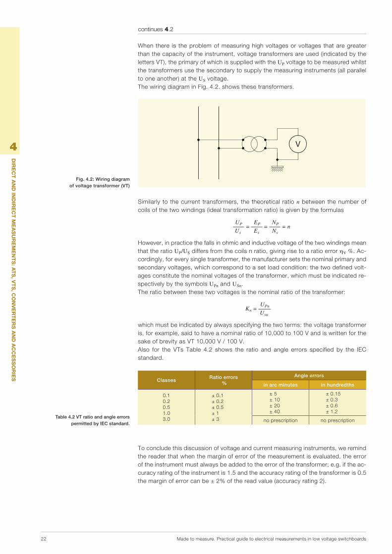
4.3
Shunts for direct currentWhenthecapacityofaninstrumentislessthanthecurrenttobemeasured,shuntsareused:theseareadditionalresistorsthatareconnectedparalleltotheinstrumenttoshuntpartofthecurrenttobemeasuredandtolimitthecurrentthatpassesthroughtheinstrumenttoanacceptablevalue.Fig. 4.3 shows the wiring diagram of a shunt for measuring a direct current via amillivoltmeter.Inordertoreachthedesiredcapacity,theshuntmustbeproportioned(orselected)accordingtothecurrentdivider;intheFig.4.3wehave:
Rs 1 I I' = I' R+Rs m
fromwhich: I' = m I = K'A n
being R+Rs I' m = = I' Rs I
themultiplyingpoweroftheshunt,nthenumberofdivisionsreadonthescale,andK'Athenewreadingconstantoftheinstrument,expressedbytheproductK'A = m KA
I’
Is
U
I’I
I
(Ri)
Rs
A B
4.4
Converters and accessoriesTheconvertersaredevicesthat, if theyareconnectedtoelectricnetworkswithanalternatingcurrentsignal,areabletoprovideadirectcurrentorvoltagesignalthatisproportionaltotheinputsignal,regardlessoftheload.Theyareparticularlysuitableforacquiringhighlyreliableandaccuratedataandarenotaffectedbytemperaturevariationsandvibrations.Theconvertersgenerallyhaveseveraloutputsthatcanbeselectedtoadapttovari-ousneeds.InadditiontotheCTs,VTsandtotheconverters,themeasuringaccessoriesare:-the interchangeable scales to adapt analogue instruments to the desired
capacities;-thecurrentandvoltageswitchesforswitchingreadersonseveralcurrentandvolt-
agephases;-thetransducers,whicharenecessaryforthedirectinsertionoftheanaloguepower-
factormeters.Currentandvoltageconvertersconvertersproduceadirectcurrentorvoltageoutputsignalthatisindependentoftheloadthatisdirectlyproportionaltotheinputvoltageorcurrentsignal.Theirelectroniccircuitensurestheirreliabilityandoperatingaccuracy,theextensionofthemeasurementfield, insensitivitytotemperaturevariationsandvibrations,andlimitedabsorptionofpowerfromthecircuitbeingmeasured.Theirrapidcentralisedacquistionofdata,evenovergreatdistancesandtheavailabilityofdifferenttypesofselectableoutletsbyactingsimplyontheadjustingminidips,makesthemsuitableforbeinginstalledinplantsthatrequireparticularattentioninproduction,distributionanduseofelectricpower.
Fig. 4.3: Measurement of direct current with millivoltmeter and external shunt
Fig. 4.1 – Current and voltage convertersFig. 4.1 – Current and voltage converters

24 Madetomeasure.Practicalguidetoelectricalmeasurementsinlowvoltageswitchboards
5Overview of ABB range
Themeasuringinstrumentsforinstallationinsideindustrialswitchboardsforprimaryandsecondarydistributionofmediumand lowvoltagearean idealcomplement toABBdeviceswithwhichtoconfigurethepanelasanintegratedfunctionssystem.The range comprises about 1000 products in the basic versions but engineering/standardisationofthecomponentsalsomakesmanyspecialversionsavailableinor-dertosatisfyanytypeofplantneed.Bothanalogueanddigitalinstrumentsareavailable:intheformerthereadingfunctionisprovidedbymovementofamovableindexalongagraduatedscale,whichenablesthedetectedvaluestobereadimmediately;thedigitalversionsare,ontheotherhand,equippedwith3or4digitdisplayLEDs,dependingonproducttype.Inbothversions,theoperatingtemperatureisbetween-10°Cand+55°C,withthepossibilityofoperatinginevenmoredifficultconditionswithoutsubstantialalterationstotheaccuracyrating.TheresistancetovibrationsandtheIPprotectiongradeareparticularlyhigh.
5.1
Analogue instrumentsInadditiontonormaldevices formeasuringelectricalparameters (voltmeters,am-meters,power-factormeters)therangeofanalogueABBinstrumentscomprisesspe-cialinstruments(meters)andaseriesofaccessories,includingthecurrenttransform-ers,whichextendtheiroperatingrange.Thereare twodistinctproduct ranges: theDINrailproducts,whicharesnap-fittedontoanordinaryDINrailandhavedimensions,compactnessanddesignthatperfectlysuit thecommandandprotectiondevicesof theSystemproMcompact®,Systemseriesandthepanelfrontinstrumentsthatcaneasilybemountedinthemediumandlowvoltageprimaryandsecondary industrialdistributionpanels.Theyare fittedbymeansofscrewbracketsthatenablethedevicetobeplacedbothinahorizontalandverticalposition, thusoptimisingspaceoccupiedandrationalisingaccess fromthefrontofthepanel.
5.1.1
DIN rail analogue instrumentsTable 5.1 summarises the characteristics ofDIN rail ABBanalogue instruments; forcompleteinformationonthetechnicalcharacteristicsofthedevices,seethetechnicalcatalogueSystemproM compact®.

Madetomeasure.Practicalguidetoelectricalmeasurementsinlowvoltageswitchboards 25
5
PAn
Or
AM
iCA
DE
llA P
rO
Du
ziO
nE
AB
B
ABB analogue measuring instruments
AC DC
-Directvoltmeters-Directammeters-AmmeterswithoutscaleforCT-Frequencymeter45-65Hz-Power-factormeterwithscalefortransducers(1mAinput)
DirectammetersAmmeterswithoutscaleforshunt
Technical characteristics
RatedvoltageUn [V] AC300,500;DC100,300
Ratedalternating directreadingcurrents indirectreading
[A] fullscalevalues5...30fullscalevalues5...2500
Rateddirectcurrents directreading indirectreading
[A] fullscalevalues0.1...30fullscalevalues5...500
Frequency [Hz] 50/60
Overloadability [%] 20comparedtoratedvoltageorcurrent
Accuracyrating [%] 1.5(0.5forfrequencymeters)
Dissipatedpower [W] seeSystemproM compact®catalogue
Modules [n°] 3
Standards EN60051
Both thedirect insertion instrumentsandthose thatare insertibleviaCTorshunts(seefigure5.1forinsertionmethods)donotrequireanauxiliarysupply.Fortheformeritissufficienttoconnectafterchoosingtheratedvoltageorcurrent;fortheothers:-choosethenominalmeasurement(current,voltage,...);-selectthecurrentorvoltagetransformer,shuntortransducer;-selecttheappropriatescale;-connecttheinstrument.
V
1 2 3 4
L1
N
A
1 2 3 4
L1
N
A
1 2 3 4
L1
N
S1 S2P1 P2
A
1 2 3 4
L1
N
5.1.2
Analogue instruments on front of panelThe range includesvoltmeters,ammeters,power-factormetersand frequencymeterswithafixedormovablereel,dependingonversions.Withthepassageofcurrentinthedevicesprovidedwithafixedreel,thetorqueproducedbytheelectromagneticfieldmovesapieceofironalongthequadraticscale,theironbe-ingconnectedtothedisplayindex.Owingtotheirparticularresistancetocurrentpeaks,fixedreeldevicesaremoresuitableforalternatingcurrent.Withthepassageofcurrentinthedevicesprovidedwithafixedreel,thetorqueproducedbytheelectromagneticfieldmovesapieceofironalongthequadraticscale,theironbeingconnectedtothedisplayindex.Theclockwisemovementoftheindexdependsonpolarity,whichmeansthatthesede-vicescanbeusedfordirectcurrentonly.Thevoltmetersandtheammeters,whichareavailablebothintheversionforalternatingcurrentandintheversionfordirectcurrent,aresuppliedinthreestandarddimensionsof48mmx48mm,72mmx72mmand96mmx96mm(specialversionsavailableonrequest).Forammeterswithoutascale,theinterchangeablescalecodewithwhichaccessorisethemisindicated.Therangeoffrontpanelmeasuringinstrumentsiscompletedbypower-factormetersand frequencymeters forapplicationsonsingle-phaseand three-phase
continues 5.1.1
Table 5.1 ABB DIN rail analogue measuring instruments
Fig. 5.1: Insertion method (direct, via CT and shunt) of the analogue instrumentsDirect insertion Insertion via CT Insertion via shunt

5
OV
Er
ViE
w O
f AB
B r
An
gE
26 Madetomeasure.Practicalguidetoelectricalmeasurementsinlowvoltageswitchboards
alternatingcurrentlinesinthethreestandarddimensionsof48mmx48mm,72mmx72mmand96mmx96mm.Fig.5.1showssomeoftheseinstrumentsandthetechnicalspecificationsaresetoutinTable5.2.Foracompletedescriptionoftheinstruments,thetypeandthecodeforordering,seethetechnicalcatalogue2CSC400002D00209SystemproMcompact®.
Technical characteristics
Max. rated insulation voltage V 650
Test Voltage V 2000effective(50Hz/1min)
Accuracy rating 1.5(0.5forfrequencymeters)
Overloadability(1) :
-ammeterwindings uptoInx10/<1sec.
uptoInx2/permanent
-voltmeterwindings uptoUnx2/<5sec.
uptoUnx1.2/permanent
Operating temperature °C -20…+40
Storage temperature °C -40…+70
Average and max. relative humidity (DIN 40040)(2)
65%(annualaverage)85%(+35°C/60daysperyear)
Vibration resistance (IEC 50-1) g(9.81m/s) 0.08-1.8(0.35mm/10-55Hz;3axes/6h)
Protection class IP52forinterior
IP00onterminals(IEC144,DIN40050)
IP40withtheterminalcovers
Manufacturing material:
-casesandfrontedge self-extinguishingthermoplasticmaterialconformingtoUL94V-0,resistanttofungiandtermites
-displayindices(DIN43802)(3) mouldedaluminium
-terminals brass
Assembly vertical/horizontalbymeansofscrewbrackets(4)
Dimensions L x H x D (DIN 43700/43718) mm 48x48x5372x72x5396x96x53
Reference Standards IECEN61010-1(1)IninstrumentswithinsertionbyCT,theoverloadmaybegreaterbecausethetransformer
containsthepeaksofsecondarycurrentwithin10In.(2)Tropicalisationenablesvaluesupto95%max.relativehumiditytobetolerated(+35°C/60
days).DIN40040requiresthemtobeprotectedfromhumditypenetratinginsidethem.Terminals,screws,washers,boltsandmagnetsaregalvanicallyprotectedagainstrustwhereastheelectricalcircuitsarecoatedwithspecialMulticolorPC52paint.
(3)Thedampingtimeforthedisplayindicesis1second.Thedetectedvaluesareresetbymeansoftheappropriateadjustment.
(4)Withpanelsthatare0.5mm–19mmthickthescrewsmustbefittedinthefixingpositionthatisnearestthefrontedgeofthemeasuringdevice.Thepanelsthatare20mm-39mmthickarefixedbyscrewsinthepositionthatisfurthestawayfromthefrontedge.
continues 5.1.2
Fig. 5.2: Analogue measuring instruments on front of panel
Table 5.2 Technical characteristics of front panel analogue measuring instruments
Max. rated insulation voltage
Test Voltage
Accuracy rating
Technical characteristics
Max. rated insulation voltageMax. rated insulation voltage
Technical characteristics
V 650
V 2000effective(50Hz/1min)
1.5(0.5forfrequencymeters)
Technical characteristics
2000effective(50Hz/1min)
1.5(0.5forfrequencymeters)
2000effective(50Hz/1min)
1.5(0.5forfrequencymeters)

5
OV
Er
ViE
w O
f AB
B r
An
gE
Madetomeasure.Practicalguidetoelectricalmeasurementsinlowvoltageswitchboards 27
5.1.3
Fig. 5.3: DIN rail switches and front panel switches
Fig. 5.4: a – 90° full scaleb – 78° full scale
with extra scale
AdvantagesAnalogueABBmeasuringinstrumentsaredistinguishedbytheirreliabilityandstabilityinindicatingthemeasuredvalue,thusmakingevenremotereadingsimple;theyalsohavethefollowingfeatures,whicharemuchappreciatedduringtheinstallationphase:-reductionofoveralldimensions;-completerangeforpanelfrontinstruments(48x48,72x72,96x96mm);-donotrequireauxiliarysupply;-areabletoprovidemultiplereadingsthankstotheselectors.Itisveryconvenientforthefitterandwholesalertohaveasingleinstrumentwitham-plecapacity (from5A to2500A),completewithawide rangeofaccessoriesandaccompanyingdevicesforinsertion,whichincludetheDINrailswitches(fig.5.3).
A final noteon the typeof scales available that are interchangeable to extend thereading scope of electrical measurements detectable with analogue measuringinstruments.Forexample,infigures5.4aand5.4btwodifferenttypesofdialsforscalesareshown:thefirsthasatraditional90°fullscale,thesecondhasa78°fullscaleplusanextrascale,whichcanbeusefullyusedwhen,duringthemeasurement,peakcurrentsthatcouldexceedthefullscalearedetected(forexampleduringthestartupphaseofanasynchronousmotor).
100
0
90°
100
0
78°
100
0
90°
100
0
78°
SCL1/A1/100 SCL1/A5/100
A final noteon the typeof scales available that are interchangeable to extend thereading scope of electrical measurements detectable with analogue measuringinstruments.Forexample,infigures5.4aand5.4btwodifferenttypesofdialsforscalesareshown:
A final noteon the typeof scales available that are interchangeable to extend thereading scope of electrical measurements detectable with analogue measuring
Forexample,infigures5.4aand5.4btwodifferenttypesofdialsforscalesareshown:
A final noteon the typeof scales available that are interchangeable to extend thereading scope of electrical measurements detectable with analogue measuring
Forexample,infigures5.4aand5.4btwodifferenttypesofdialsforscalesareshown:
A final noteon the typeof scales available that are interchangeable to extend thereading scope of electrical measurements detectable with analogue measuring
Forexample,infigures5.4aand5.4btwodifferenttypesofdialsforscalesareshown:

5
OV
Er
ViE
w O
f AB
B r
An
gE
28 Madetomeasure.Practicalguidetoelectricalmeasurementsinlowvoltageswitchboards
5.2
Digital instrumentsTherangeofABBdigitalinstrumentsisparticularlywide:alongsidetraditionalmeas-uringinstruments(voltmeter,ammeter,frequencymeter),bothintheDINrailandinthepanelfrontversion,thereare:-themultimetersoftheDMTMEseriesthatnotonlyenablethemainelectricalquanti-
tiestobemeasuredbutalsostorethemaximum,minimumandaveragevaluesofthemainelectricalquantitiesandcountactiveandreactiveenergy;
-MTMEandANRseriesnetworkanalysers thatnotonlymonitor thequalityof theenergyinrealtimebutarealsoabletodisconnectloadsandsendalarmsignals;
-energymeters;-temperaturemeasuringunits.Inaddition,awiderangeofaccessoriesmaketheseinstrumentsuniversalforelectricplantsandnetworksinthefollowingrange:-voltageupto600V-currentupto999A-frequency:from40to80HzItshould lastlybenoted that theabsenceofpartssubject towear through frictionensuresalongeroperatinglifeandparticularlyhighregulatingaccuracy.
5.2.1
DIN rail digital instrumentsTable5.3summarisesthecharacteristicsofABBDINraildigitalinstruments;forcom-plete information on the technical characteristics of the devices, see the technicalcatalogueSystemproM compact®.
Alltheinstrumentsofferhighmeasuringaccuracy(0.5rating)andeasyandaccurateread-ingofthemeasuredvalues:therangeiscompletedbyinstrumentswithaninternalrelaywhichdisplayandmonitorameasurementandwhenaprogrammablethresholdisexceededtheytriparelaycontactanddisplaythealarmcondition.Thealarmthresholdcanbepro-grammedasaminimumormaximumthreshold.Theminimumandmaximumrecordedpeakvaluesaresavedintheinstrument'spermanentmemory.Therelayactionisprogram-mable.Thefactorysettingisnormallyopencontactthatclosesonlyintheeventofanalarm.Inprogrammingmodetheinstrumentcanbeconfiguredinsuchawaythattherelayworkswithpositivesafety:inthiscasetherelaywillcloseduringcorrectoperationandwillopenintheeventofanalarmorpowerfailure.Theinstrumentwiththerealycanbeusedalter-nativelyeitherasaminimumrealyorasamaximumrealybutnotsimultaneouslyforbothalarms.Theintrumentsalsoenabletheminimumandmaximummeasurementvaluetobestoredanddisplayed.
Table 5.3 ABB digital measuring instruments

5
OV
Er
ViE
w O
f AB
B r
An
gE
Madetomeasure.Practicalguidetoelectricalmeasurementsinlowvoltageswitchboards 29
5.2.2
Front panel digital instrumentsTheseinstrumentsareprovidedwiththree-digitredLEDsdisplaystoindicateimme-diatelytheelectricalvaluesdetected.Afewsimpleoperationsenablethemultiscalefunctiontobeaccessedthatenablestherangeofdisplayablequantitiestobevariedorextended.Theproduct rangecomprisesvoltmeters,ammeters fordirector indirectmeasure-mentsusingdevicetransformersandshuntsandtemperaturemeasuringunits.Theapplicationcanberuninbothalternatinganddirectcurrent.Theabsenceofmechanicalpartsthataresubjecttowearmakestheseinstrumentsveryreliableanddurable.Fig.5.1showssomeoftheseinstrumentsandthetechnicalspecificationsaresetoutinTable5.4.Foracompletedescriptionoftheinstruments,thetypeandthecodeforordering,seethetechnicalcatalogue2CSC400002D0208SystemproMcompact®.
continues 5.2.1
Fig. 5.5: Insertion method of different ABB digital instruments
Fig. 5.6: Panel front digital measuring instruments
Wiring diagrams for digital instruments, both DIN rail and front panel
VLMD-1-2 and VLMD-1-2-RVLMD P and VLMD-R P
� � � �� � � � � �� �
� � � �� � � � � �� �
–
FRZ-DIG
AMTD-1 and AMTD-1-RAMTD-1 P and AMTD-1-R P
AMTD-2 and AMTD-2-RAMTD-2 P and AMTD-2-R P
*Onlyforinstrumentswithoutputrelay

5
OV
Er
ViE
w O
f AB
B r
An
gE
30 Madetomeasure.Practicalguidetoelectricalmeasurementsinlowvoltageswitchboards
Technical characteristics
Power supply [V] 230VCA
Rated frequency [Hz] 50÷60
Ammeter full scale value [A] 5,20,25,40,60,100,150,200,250,400,600
Voltmeter full scale value [V] 300,500
Frequency meter range [Hz] 35...400
Tripping delay [s] 1,5,10,20,30
Hysteresis [%] 5,10,20,30setthreshold
Output pins [V] 3-4
Output relay [A] NO
Rated voltage relay [In/Vn 230VCA
Rated current relay [%] AC116,AC153
Relay configuration NOrelayclosesinalarmstatus
NCrelayopensinalarmstatus,positivesafety
Overload [In/Vn] 1,2
Accuracy class [%] ±0,5fullscale±1digitat25°C
Max. signal input value for ammeters [°C] 5ACA/60mVDC
Display [°C] 3digitLEDdisplay
Operating temperature [VA] -10…+55
Storage temperature [mm] -40...+70
Protection degree IP20
Power consumption 4
Modules 3
Overall dimensions front panel devices
36x72x61.5(51.5depthinsidetheswitchboard)
Standard IECEN61010
5.2.3
DMTME multimetersTheinstrumentsoftheDMTMEseriesaredigitalmultimetersthatenablesthemainelec-tricalquantitiestobemeasured(TRMS)in230/400VACthree-phasenetworks,themaxi-mum,minimumandaveragevaluesofthemainelectricalquantitiestobestoredandtheactiveandreactiveenergytobecounted.ThemultimetersoftheDMTMEseriesenablethesameinstrumenttoactasavoltmeter,ammeter,power-factormeter,wattmeter,varmeter,frequencymeter,activeandreactiveenergycounter,hourcounter.Thispermitssignificantsavingsbecauseboththesizeofthepanelandwiringtimearereduced.Fig.5.7ashowsaDMTMEDINrail(6-modules)multimeterthatcanbeinsertedviaCT.../5Aformeasurementson230/400VAClines(displayablemeasurements:V-I-W-VA-Hz-kWh-kVARh);theDMTME-I-485versionisprovidedwithtwodigitaloutletsthatcanbeprogrammedasalarmthresholdsandpulseoutletsforremotecontrolofenergycon-sumptionandaserialdoorRS485.Fig.5.7bshowsthemultimeterstobeinstalledinthefrontofthepanelinthetwover-sions:traditional96x96mmand72x72mminthemorecompactversionthatisidealforinstallationinpowercentresinwhichcompactdimensionsarerequired.FromtheserialportRS485severalmultimetersandotherdigital instrumentscanbeconnectedtothenetworkviatheModbusRTUprotocol.AlltheversionsaresuppliedwithaCDcontainingthe instruction manuals, technical documentation, communicaion protocol andDMTME-SWtool.
continues 5.2.2
Table 5.4 Technical characteristics of digital measuring instruments
on front of panel
Fig. 5.7a DIN rail multimeter DMTME

5
OV
Er
ViE
w O
f AB
B r
An
gE
Madetomeasure.Practicalguidetoelectricalmeasurementsinlowvoltageswitchboards 31
Technical characteristics
Rated voltage [Vrms] 230+15%-10% DMTME-72andDMTME-96
[Vrms] 240+15%-10% DMTME-72andDMTME-96
[Vrms] 400+10%-10% DMTME-72
[Vrms] 400+10%-10% DMTME-72
[Vrms] 115+15%-10% DMTME-96
[Vrms] 120+15%-10% DMTME-96
Frequency [Hz] 45…65
Power input [VA] <6
Safety fuse 0.1A
Voltmeter inputs
Range [Vrms] 10…500V(L-N)
Nondestructivemax. [Vrms] 550
Impedance(L-N) [MW] >8
Current inputs (only CT .../5 A external)
Range [Arms] 0.05…5
Overload 1.1permanent
Measurements accuracy
Voltage ±0.5%F.S.±1digitinrange
Current ±0.5%F.S.±1digitinrange
Activepower ±1%±0.1%F.S.fromcosj=0.3tocosj=-0.3
Frequency ±0.2%±0.1Hzfrom40.0to99.9Hz
±0.2%±1Hzfrom100to500Hz
Energy count
Maximumcountedvaluepersinglephase 4294.9MWh(MVarh)withKA=KV=1
Maximumcountedthree-phasevalue 4294.9MWh(MVarh)withKA=KV=1
Accuracy Class1
Max.powerconsumption 1.4foreachinput(withImax=5Arms)
Digital outputs
Pulseduration 50msOFF(min)/50msON
Vmaxoncontact 48V(peakDCorAC)
Powerconsumption 450mW
Maximumfrequency 10pulses/sec
Imaxcontact 100mA(maxDCorAC)
Insulation 750Vmax
Confi gurable parameters
VTtransformationratio 1…500
CTtransformationratio 1…1250
Freehourcounter [h] 0…10,000,000,resettable
Countdown [h] 1…32,000
Operating temperature [°C] 0…+50
Storage temperature [°C] -10…+60
Relative humidity 90%max.(withoutcondensation)a40°C
Overall dimensions [mm] 96x96x103 DMTME-96
[mm] 72x72x90 DMTME-72
5.2.4
MTME and ANR network analysersTheMTMEseriesnetworkanalysers(Fig.5.8a)enablethemainelectricalquantitiestobemeasuredastrueeffectivevaluesin230/400VACthree-phasenetworks,themaximum,minimumandaveragevaluesofthemainelectricalquantitiestobestoredandtheactiveandreactiveenergytobecountedontotalorpartialcounters.OwingtotheTHD(totalharmonicdistortion)measurementasanabsoluteandper-centagevalue, it ispossible tomonitor in real time thequalityof theenergyof theplantandtopreventdamagetothedevices.MTMEnetworkanalysersarealsoable,dependingon theversion, tomanageanddisconnectloadstosaveenergyandoptimiseconsumptionandtosendalarmsignalsrelatingto34quantitiesviatworelayoutlets.
continues 5.2.3
Figura. 5.7b: Multimetri fronte quadro DMTMEFigura. 5.7b: Multimetri fronte quadro DMTME
Fig. 5.8a Network analyser MTME-485-LCD-96

5
OV
Er
ViE
w O
f AB
B r
An
gE
32 Madetomeasure.Practicalguidetoelectricalmeasurementsinlowvoltageswitchboards
VersionswithanRS484portenableallthequantitiesofaninstrumentorofanetworkofinstrumentstobereadandmontoredlocallyorremotely.ThelocaldisplayofthequantitiesisshownonanLCDdisplaywithhigh-visibilitybacklighting.Thefollowingfeaturesarealsoavailable:-automaticrecognitionofthedirectionoftheCT(selectable)-programmablemainscreen-accesspassword-frimwarethatisupdatableviaPCAlltheversionsaresuppliedwithaCDcontainingtheinstructionmanuals,technicaldocumentation,communicaionprotocolandDMTME-SWsoftware.
Main characteristics of the MTME-485-LCD-96 network analyser
Rated voltage [V rms] 230 +15% - 10%
[V rms] 240 +15% - 10%
[V rms] 115 +15% - 10%
[V rms] 120 +15% - 10%
Frequency [Hz] 45…65
Power input [VA] < 6
Safety fuse T0, 1A
Voltmeter inputs
Range [V rms] 10…500 V (L-N)
Non destructive max. [V rms] 550
Impedance (L-N) [MΩ] > 2
Current inputs (always use CT .../5 A)
Range [A rms] 0.05…5
Overload 1.1 permanent
Measurements accuracy
Voltage ±0.25% ±0.3% F.S.
Current ±0.25% ±0.3% F.S.
Active power ±0.5% ±0.1% F.S. from cosj = 0.3 to cosj = -0.3
Frequency±0.2% ±0.1Hz from 40.0 to 99.9 Hz
±0.2% ±1Hz from 100 to 500 Hz
Energy count
Maximum counted value per single phase 4294.9 MWh (MVarh) with KA = KV = 1
Maximum counted three-phase value 4294.9 MWh (MVarh) with KA = KV = 1
Digital outputs
Pulse duration 50 ms OFF (min)/ 50 ms ON
Vmax on contact 48 V (peak DC or AC)
Power consumption 450 mW
Maximum frequency 10 impulsi/sec
Imax contact 100 mA (max DC or AC)
Insulation 750 Vmax
Configurable parameters
VT transformation ratio 1…500
CT transformation ratio 1…1000
Operating temperature [°C] 0…+50
Storage temperature [°C] -10…+60
Relative humidity 90% max. (without condensation) at 40°C
Overall dimensions [mm] 96x96x103
Ifevenmoreadvancedanalysisfunctionsarerequested,therangeofABBpanelinstru-ments,andANRnetworkanalysersenablenetwork,informationandalarmparametersto be measured and recorded by routing the data to supervision and monitoringsystems.TheSW01softwarewithwhichtheyareprovidedmanagestheprogramming,displayandrecordingofthemeasurementdataandofthealarms.Performanceistoplevel:-itispossibletomeasure,recordandanalyseover60electricparameters;
continues 5.2.4

5
OV
Er
ViE
w O
f AB
B r
An
gE
Madetomeasure.Practicalguidetoelectricalmeasurementsinlowvoltageswitchboards 33
-thevoltageandcurrentsaremeasuredastrueandeffectivevalues(“trueRMS”)with0.5ratingaccuracy;
-communcationsareprovidedon:programmableanalogueoutlets,digitaloutletsforcontrols,pulsesandalarms,statusand/ornon-electricparametersacquisition,Mod-bus,Profibus,ASCII,Ethernetprotocols;
TheANRnetworkanalysersareavailableinthe96x96mmrecessedformatorinthe144x144mmversion(thelatterhaveexpansioncards)andhavegraphicback-lighted128x128pixelgraphicLCDdisplays.Theirusepermitsextremelyefficientmonitoringofthequalityoftheenergyinbothsin-gle-phaseandthree-phasedistributionnetworksviainstantaneousandhistoricalvari-ationsofvoltage,ofsupplyinterruptions,ofmicrodisturbancesandofharmoniccom-ponentsuptothethirty-firstorderandwaveshapes,andoptimisationofenergycoststhroughpromptandhistoricalanalysisofconsumptionoverfourperiodsinadaythatarefreelyselected,withmonitoringanddisconnectionofloads.
Main characteristics: ANR 144-230 network analyser
Packaging
Overall dimensions [mm] 96 x 96 x 130 - 144 x 144 x 66 IEC 61554
Max setion of wires [mm2] 2.5
Protection class IP52 frontal-IP20 terminal boards EN 60529
Weight [g] 430
Display
Graphic LCD 128x128 points with adjustable contrast with LED back lighting
Display dimensions [mm] ANR96: 50 x 50-ANR144: 70 x 70 IEC 60529
Voltage (TRMS)
Direct measurement [V] 10 - 600
Transformation ratio range kTV [V] 0.01 - 5000,00
Permanent overload 750, above this value a voltage transformer must be used
Consumption [VA] 0.2
Input resistance [MW] > 2
Current (TRMS)
3 insulated inputs with internal CTs .../5 A [A] 0.01 - 5
Minimum current measurement [mA] 10
Consumption [VA] 0.2
Display
Overload [A] 10 (100 A for 1 second)
Transformation ratio range kCT 0.01 - 5000,00
THD
Voltage and current Up to 31st harmonic
Frequency
[Hz] 30 - 500
Accuracy
Current [%] < 0.5 EN 61036
Voltage [%] < 0.5
Power [%] < 1
Power factor [%] < 1
Active energy [%] < 1 IEC 62052-11
Reactive energy [%] 2 IEC 62053-23
Separate power supply
ANR96-230, ANR96P-230, ANR144-230 [V] 85 ÷ 265 AC/DC
ANR96-24, ANR96P-24, ANR144-24 [V] 20 ÷ 60 AC/DC
Internal fuse 5 x 20 mm 315 mA 250 V Fast
Conditions of use
Operating temperature [°C] -10 ÷ +50
Storage temperature [°C] -15 ÷ +70
Relative humidity [°C] 90% non condensated
continues 5.2.4
-thevoltageandcurrentsaremeasuredastrueandeffectivevalues(“trueRMS”)with
-communcationsareprovidedon:programmableanalogueoutlets,digitaloutletsforcontrols,pulsesandalarms,statusand/ornon-electricparametersacquisition,Mod-
TheANRnetworkanalysersareavailableinthe96x96mmrecessedformatorinthe144x144mmversion(thelatterhaveexpansioncards)andhavegraphicback-lighted
Theirusepermitsextremelyefficientmonitoringofthequalityoftheenergyinbothsin-gle-phaseandthree-phasedistributionnetworksviainstantaneousandhistoricalvari-ationsofvoltage,ofsupplyinterruptions,ofmicrodisturbancesandofharmoniccom-ponentsuptothethirty-firstorderandwaveshapes,andoptimisationofenergycoststhroughpromptandhistoricalanalysisofconsumptionoverfourperiodsinadaythat
Fig. 5.8b: Network analyser ANR 144-230

5
OV
Er
ViE
w O
f AB
B r
An
gE
34 Madetomeasure.Practicalguidetoelectricalmeasurementsinlowvoltageswitchboards
Insulation
Insulation voltage 3700 V AC rms for 1 minute
Serial output
RS485
Programmable Baud rate [bps] 1.200 - 19.200
Communication protocols Modbus RTU, ASCII
Internal memory
For ANR96 and ANR144 [kbyte] 128 (usable 80)
For ANR96P [Mbyte] 1
Type of memory Permanent data memory using internal buffer battery
Data storage period 5 years at 25°C
Internal clock
RTC clock IEC EN 61038
Accuracy [ppm] 5
Digital outputs
Max setion of wires [mm² ] 0 ÷ 2.5
External pulse voltage [V] 12 ÷ 230 V AC/DC
Max. current [mA] 150
Digital inputs
Voltage [V] 12 - 24 DC
5.2.5
Temperature measuring unitsTheyareusedtomonitortemperaturelevelsandtheventilationfunctionsofelectricmachines,transformers,motors,etc.Preventivecontroloftemperatureenablesmal-functionsandoverloadingtobeavoided.PT100andRTDprobesareusedtomeasuretemperatures.Foreachmeasurementchannel, twoalarm levels (trippedalarms)canbeset that trip twooutput relays toremotelysignalifacriticaltemperaturelevelhasbeenreached.Therecordedvaluesandpossiblealarmstatusesaredisplayedonthe3-digitdoubledisplayonthefrontofthedevice,fromwhichtheadjustingfunctionsofthedevicescanbeaccessedviathe5programmingkeys.Inaddition,thecontrolunitsenablethemaximumvaluestobe stored, each intervention to be stored and ventilation inside the panel to becontrolled.Fig.5.9showsthepanelfrontcontrolunitTMD-T4/96
Main characteristics of the TMD-T4/96
Auxiliary supply voltage [V] 100 … 125, 220 … 240, 380 … 415/50-60 Hz
Max. consumption [VA] 4
Measuring inputs 2 RTD Pt100
Measuring range [°C] 0…+220 ±2 °C
Trip delay - hysterisis 5 s/2 °C
Measurement display LED display, 7 segments, digits
Outputs 1 12 V DC, 3 NA-C-NC relay, 8 A resistive load
Outlet functions alarm, trip, ventilation, autodiagnosis
Programmable functions ALARM, TRIP, HOLD, FAN, T. MAX
Connections extractable screw terminal boards, max. section 2.5 mm2
Insulation [Vrms] 2500/50 Hz - 1 min
Protection class
IP52 on front panelcan be increased to IP65 with optional
protection cap code 2CSG524000R2021
IP20 on back panel
Operating temperature [°C] -10...+55, max. humidity 90%
Storage temperature [°C] -25 ... +80
StandardsIEC EN 50081-2, IEC EN 50082-2,
IEC 14.1, IEC EN 60255
continues 5.2.4
Fig. 5.9 – TMD-T4/96 unit

5
OV
Er
ViE
w O
f AB
B r
An
gE
Madetomeasure.Practicalguidetoelectricalmeasurementsinlowvoltageswitchboards 35
5.2.6
Electronic energy metersThewiderangeofDINrailABBenergymetersformeasuringenergy issummarisedinTable5.5.Foradescriptionofthespecifictechnicalcharacteristicsofeverysingledevice,seecatalogueSystemproM compact®.EveryelectricitymetermadebyABBistypeapproved,verifiedandissuedwithacertificateofcomplianceaccordingtoMIDrequire-ments,Measuring InstrumentsDirective.ABBhaschosen typeapprovalaccording toAnnexBandinitialverificationaccordingtoAnnexD.theproductmustfulfillrelevantpartsofEN50470andbeassessedbyaNotifiedBodythatthenissuesacertificateforthatproduct.ABBuseNMi,anindependentexpertformetrologytesting,certifyingandcali-brating,foranytask.Theenergycounterscanbeprofitablyusedinbothresidential/tertiaryenvironmentsandinindustrialenvironments.Atypicalexampleofthefirstcaseistheinteriorofashoppingcentrewherelocalenergyconsumptioncanbemeasured,arecordofconsumptioncanbeestablished,thebuildingcanbemanagedremotelyandbeintegratedwithamanage-mentsystemowingtodifferentprotocolschosenbythecustomerModbusRTU,M-bus,LonWorkandEthernet,GSM/GPRS,EIB/KNXthankstotheserialadapters.Asthecurrentdirectionisrecognisedautomatically,thecountersalsoensuresafeanderror-freeinstallation.Equallysignificantaretheinstallationadvantagesoftheenergymetersinindustrialplants,wherecertainspecificfeaturesofthedeviceareimmediatelyreflectedineconomicad-vantagesandreliability,asshowninTable5.6.
Single-phase energy meters Three-phase energy meters
ODINsingle DELTAsingle ODIN DELTAplus
Directmeasurementupto65A
Directmeasurementupto80A
Directmeasurementupto65AindirectbyCT(5/5-900/5A/A)
Directmeasurementupto80AindirectbyCT(1-999A)
Tab. 5.5 – DIN rail electronic energy meters

5
OV
Er
ViE
w O
f AB
B r
An
gE
36 Madetomeasure.Practicalguidetoelectricalmeasurementsinlowvoltageswitchboards
5.3
Accessories for measuring instruments
5.3.1
Serial communication adaptersTheypermitserialcommunicationofdatabetweenenergycountersandtheremotesupervisionsystem;theyhavereduceddimensions (2DINmodules)andcaneasilybeinstalledontheDINsectionandcanbecoupledwiththeenergycounterasshowninFig.5.10.
Theirmainfunctionistoconvertopticalsignalscomingfromthecountersinthepow-erlineserialcommunicationmeans,pair,etcandintheselectedprotocols(ModbusRTU,Meter-bus,TCP/IP,KNX/EIB,GSM/GPRS).
Serial converter RS485 / RS232ThemultifunctionserialconverterCUS(fig.5.11)isusedinallcasesinwhichitisnecessarytoconvertormanagetheseriallinesEIA-232(RS-232),EIA-485(RS-485)andEIA-422(RS-422).Theconnectionbetweendevicesthatusethesetypesofcommunicationbus(suchasforexamplePLCs,measuringandcontrolinstruments,connectionbetweendevicesandcomputerswithspecificapplicationsoftwareinstalled,etc)oftenrequiresthetypeofseriallinetobeconverted,thesignalonthelinetobeamplied,differentpartsofthecommunicationnetworktobeinsulatedetc.TheCUSconverteristhususedwidely,asithasbroadapplicationalscopewithdifferentadjustmentsandsettingsthatenableittobeusedinthemostwidelyvaryingapplications.
CUSensuresthegalvanicallyinsulatedconversionbetweentheRS-232,theRS422-485sideandthesupplysource.Theversatilityofthedeviceallowsdifferentoperatingmodes:-RS-232conversiontoRS-422fullduplex-RS-232conversiontosingleRS-485halfduplex-RS-232conversiontodoubleRS-485halfduplex-RS-485repeater(andmonitorfunctiononRS-232)
Themainapplicationsare:-networksformultipointdatatransmission-long-distanceserialconnections-galvanicseparationofperipherals-extensionofRS-485lines
Fig. 5.10: Coupling energy meter-adapter
Fig. 5.11 – CUS serial converter

5
OV
Er
ViE
w O
f AB
B r
An
gE
Madetomeasure.Practicalguidetoelectricalmeasurementsinlowvoltageswitchboards 37
Main characteristics of serial converter RS485 / RS232
Supply voltage [V] 230 V AC ±20%
Frequency [Hz] 50-60
Power input [VA] 7 max
Dissipated power [W] 3.5
Line fuse 500 mA internal
Dimension, supply terminals [mm2] 2.5 max
Dimension, RS485-422 terminals [mm2] 2.5 max
Connection RS232 Sub-D 9-pole female (DB9)
Length, max. RS232 line [m] 15
Length, max. RS485-422 line [m] 1200
Units that can be connected in multidrop mode Max 32
Operating temperature [°C] -20…+60
Storage temperature [°C] -20...+80
Modules [n°] 6
5.3.2
Current transformersTheyareusedtotransformprimarycurrents(max.6000A)intolow-currentsecond-arycurrents.../5Asupplyingindirectlyanalogueanddigitalmeasuringinstruments.Theyareavailablewithbothawoundwindingandathroughwinding.Inthefirstcasetheyaresuppliedtogetherwiththebarorprimaryterminal;inthesecondthehaveaholeinwhichtoinsertthebarorcablethatconstitutestheprimary.Therangeisverycomprehensive:foradescriptionofthespecifictechnicalcharac-teristicsofeverysingledevice,seethetechnicalcatalogueSystemproMcompact®.SystemForexample,infigure5.12threecurrenttransformerswithdifferentfeaturesareshown:1)DINrailtransformer.2)transformer,withwoundprimary,primarycurrentonbar,25mm,secondaryon
terminals;3)transformerwiththroughprimary: forprimarycurrentfromcable, fromhorizontal
barorfromverticalbar;
Current transformer range
DINrailtransformerTRFM Transformerwithwoundprimary
Transformerwiththroughprimary
Choice of primary
CT3 CT4 CT6 CT8 CT8-V CT12 CT12-V
Section conductor
[mm]
21 25 50 2x30 2x35 2x50 2x35
30x10 40x10 60x20 80x30 - 125x50 -
20x10 40x10 - - 3x80x5 - 4x125x5
continues 5.3.1
Fig. 5.12: Example of current transformers

5
OV
Er
ViE
w O
f AB
B r
An
gE
38 Madetomeasure.Practicalguidetoelectricalmeasurementsinlowvoltageswitchboards
5.3.3
Voltage transformersTheyareusedtotransformprimaryvoltagesupto600Vintosecondaryvoltagesof.../100Vmaxwithwhichsupplyindirectlyallmeasuringinstruments,bothanalogueanddigital.Theyareavailableinthecasemadeofself-extinguishingrating1plastic(Fig.5.13a)orina0.5ratingmetalcase(Fig.5.13b).Theycanbeinstalledinthree-phasenet-works,withorwithoutneutral.Fortheselectionofthesingledevices,seethecata-loguefortheSystemproMcompact®.
Examples of voltage transformers
a)inplasticcase b)inmetalcase
5.3.4
Shunts for direct currentTheshuntshave60mVvoltageandmustbeusedwithamaximumloadof0.25ΩincombinationwiththeDCmeasuringinstrumentsformeasuringcurrent.Thetwo-polecablewithwhichtheyarefittedis1mlongandhasa1.4mm2sectionthatisequaltoaresistanceof0.025Ω.Toensurethattheshuntsoperatecorrectly,checkthat:-assemblycanbebothhorizontalorvertical(thehorizontalpositionenablestheheat
tobedispersedbetter);-thecontactsurfacemustbeusedcompletelyandbeclean;afterconnecting,cover
withaspecificgrease;-thescrewsandboltsmustbecorrectlytightened;-theshuntsmustbesufficientlyventilated;astheyarenot insulated,theymustbe
protectedagainstaccidentalcontacts.
Fig. 5.15: Method of insertion of shunt into measuring circuit
V
1 2 3 4
L1
N
A
1 2 3 4
L1
N
A
1 2 3 4
L1
N
S1 S2P1 P2
A
1 2 3 4
L1
N
INSTRUMENT
+ –
+
–G
+
–U
Fig. 5.13: Examples of voltage transformers
Fig. 5.14: Direct current shunt

5
OV
Er
ViE
w O
f AB
B r
An
gE
Madetomeasure.Practicalguidetoelectricalmeasurementsinlowvoltageswitchboards 39

40 Madetomeasure.Practicalguidetoelectricalmeasurementsinlowvoltageswitchboards
6The measurements
6.1
TRMS Measurements
6.1.1
Linear loadsWhentheelectricity isgeneratedbytheelectricpowerutility, thewaveformof thevoltageissinusoidal.Thetraditionalloadsare,forexample:-incandescentlampsandheaters(resistiveloads);-motorsandtransformers(inductiveloads),absorbsinusoidalcurrentiftheyarecon-
nectedtoasinusoidalvoltagesource.Thecurrentabsorbedbyapurelyresistiveorinductiveloadhasthesamepatternandthusthesamewaveformasthevoltagethatsuppliesit.Thus,inlinearloadsthewaveformof thecurrent is thesameasthevoltagewave form(botharesinusoidal)andtherearenoharmonics.
V
1 2 3 4
L1
N
A
1 2 3 4
L1
N
A
1 2 3 4
L1
N
S1 S2P1 P2
A
1 2 3 4
L1
N
–
1,5
1
0,5
0
-0,5
-1
-1,5
0 10 20 30 40 50 60 70 80
i(t)v(t) i(t) 90° delaycompared with
v(t)
inductive load
1,5
1
0,5
0
-0,5
-1
-1,5
0 10 20 30 40 50 60 70 80
i(t)v(t) i(t) 90°ahead of v(t)
capacitive load
V
1 2 3 4
L1
N
A
1 2 3 4
L1
N
A
1 2 3 4
L1
N
S1 S2P1 P2
A
1 2 3 4
L1
N
–
1,5
1
0,5
0
-0,5
-1
-1,5
0 10 20 30 40 50 60 70 80
i(t)v(t) i(t) 90° delaycompared with
v(t)
inductive load
1,5
1
0,5
0
-0,5
-1
-1,5
0 10 20 30 40 50 60 70 80
i(t)v(t) i(t) 90°ahead of v(t)
capacitive load
6.1.2
Non linear loadsTechnologyandtheneedtoreduceconsumption,whichisincreasinglyrequestedbythemarket,haveledtonewhigh-performanceloadsbeingdevelopedthatareabletooperatewithlessenergyabsorption.
Fig. 1: Sinusoidal linear voltage v(t) and current i(t) pattern
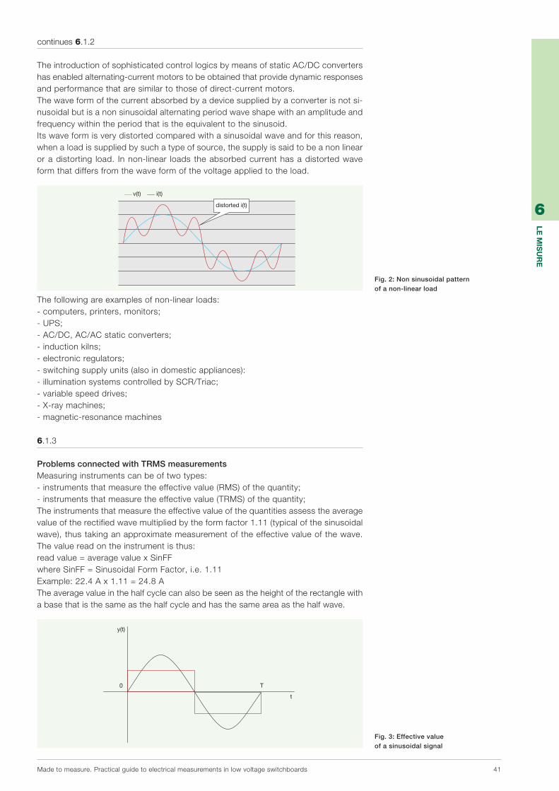
Madetomeasure.Practicalguidetoelectricalmeasurementsinlowvoltageswitchboards 41
6
lE M
isu
rE
TheintroductionofsophisticatedcontrollogicsbymeansofstaticAC/DCconvertershasenabledalternating-currentmotorstobeobtainedthatprovidedynamicresponsesandperformancethataresimilartothoseofdirect-currentmotors.Thewaveformofthecurrentabsorbedbyadevicesuppliedbyaconverterisnotsi-nusoidalbutisanonsinusoidalalternatingperiodwaveshapewithanamplitudeandfrequencywithintheperiodthatistheequivalenttothesinusoid.Itswaveformisverydistortedcomparedwithasinusoidalwaveandforthisreason,whenaloadissuppliedbysuchatypeofsource,thesupplyissaidtobeanonlinearoradistorting load. Innon-linear loads theabsorbedcurrenthasadistortedwaveformthatdiffersfromthewaveformofthevoltageappliedtotheload.
i(t)v(t)
distorted i(t)
y(t)
0 T
t
Thefollowingareexamplesofnon-linearloads:-computers,printers,monitors;-UPS;-AC/DC,AC/ACstaticconverters;-inductionkilns;-electronicregulators;-switchingsupplyunits(alsoindomesticappliances):-illuminationsystemscontrolledbySCR/Triac;-variablespeeddrives;-X-raymachines;-magnetic-resonancemachines
6.1.3
Problems connected with TRMS measurementsMeasuringinstrumentscanbeoftwotypes:-instrumentsthatmeasuretheeffectivevalue(RMS)ofthequantity;-instrumentsthatmeasuretheeffectivevalue(TRMS)ofthequantity;Theinstrumentsthatmeasuretheeffectivevalueofthequantitiesassesstheaveragevalueoftherectifiedwavemultipliedbytheformfactor1.11(typicalofthesinusoidalwave),thustakinganapproximatemeasurementoftheeffectivevalueofthewave.Thevaluereadontheinstrumentisthus:readvalue=averagevaluexSinFFwhereSinFF=SinusoidalFormFactor,i.e.1.11Example:22.4Ax1.11=24.8ATheaveragevalueinthehalfcyclecanalsobeseenastheheightoftherectanglewithabasethatisthesameasthehalfcycleandhasthesameareaasthehalfwave.
i(t)v(t)
distorted i(t)
y(t)
0 T
t
continues 6.1.2
Fig. 3: Effective value of a sinusoidal signal
Fig. 2: Non sinusoidal pattern of a non-linear load

6
Th
E M
EA
su
rE
ME
nT
s
42 Madetomeasure.Practicalguidetoelectricalmeasurementsinlowvoltageswitchboards
Theinstrumentsthatmeasurethetrueeffectivevalue(TRMS)ofthequantityperformthefollowingoperations:-samplingofthewaveovertheentireperiod;-squaringthesamples;-addingupthesquaresandmakingtheaverage;-thencalculatingthesquareroot.
YRMS=n
Yi
2
i=1
n
basic
200
100
0
-100
-200
7th HARM
5th HARM
resulting distorted wave
1 n/2 n
Theinstrumentsthatmeasureonlytheeffectivevalue(RMS)ofthequantitiesprovidethevaluecorrespondingtothetrueeffectivevalue(TRMS)onlywhentheymeasurequantitieswithaperfectlysinusoidalwaveform.Inordertohaveaccuratemeasurementsinthepresenceofdistortedwaves,anden-ablethepowertobedeterminedcorrectly,instrumentsthatareabletomeasurethetrueeffectivevalue(TRMS)ofthequantitiesmustalwaysbeused.
6.2
Harmonic distorsion and THDHarmonicsaresinusoidalwaveswithfrequenciesthatarethesameasentiremultiples(harmonicorder)ofthebasicwave.Atnetworkfrequency(50Hz),thedominantharmonicsgeneratedbythenonlinearloadsaretheunevenharmonics:-thethirdharmonic(150Hz);-thefifthharmonic(250Hz);-theseventhharmonic(350Hz)etc.
YRMS=n
Yi
2
i=1
n
basic
200
100
0
-100
-200
7th HARM
5th HARM
resulting distorted wave
1 n/2 n
Nonlinearloads,includingthoselistedbefore,aresourcesofcurrentharmonics.Whentheconcentrationof thesedevices increases inanelectricplant,theirinfluenceontheinternalelectricdistributionsystemalsoincreases.Whenthecurrentharmonicsreachasufficientamplitude,thereisthephenomenonofinteractionwiththeinternaldistributionsystemandwithotherdevicesinstalledinthesameplant.Thecurrentharmonicsinteractwiththeimpedanceofthedistributionsystem,creat-ingvoltagedistorsionsandenergyloss.Whentheharmonicdistorsionreachesexcessivelevels,thedevicesmayfacediffer-entproblems,inparticular:-untimelytrippingofthedifferentialrelays;-currentincreaseinthephaseconductors;-significantcurrentincreaseintheneutralconductorwithconsequentoverheating;-overheatingofthetransformersandincreaseinnoise;
continues 6.1.3
Fig. 4: True effective value of a sinusoidal signal
Fig. 5: Wave form with harmonic components

6
Th
E M
EA
su
rE
ME
nT
s
Madetomeasure.Practicalguidetoelectricalmeasurementsinlowvoltageswitchboards 43
-increaseinthespeedofthediscintheinductionenergycounters;-prematureagingoftheelectricalcomponents;-faultsinthepower-factorcorrectioncapacitors;-faultsinthefiltercapacitorsandlittlestand-bypowerintheUPS;-reductionofpowerfactorandimpositionofpenaltiesbyelectricpowerproviderWhentheloadsarebalancedalsotheharmoniccurrents,likethephasecurrentsatthebasicfrequency(50Hz),tendtocanceleachotherout.Thisprincipleappliestoalltheharmonicswiththeexceptionofunevenharmonicsthataremultiplesofthree,which,unliketheothers,areaddeduptogetherandreturnex-clusivelythroughtheneutralconductor.Inelectricplantssuppliedbythree-phasesystems,star-connectednon-linearloadsthatgenerateharmonicsthataremultiplesofthreemaycausepossibleoverloadsandthusoverheatingoftheneutralconductors.Thevectordiagrambelowshowsthequantitiestrendforthebasicfrequency,forthefifthharmonicandforthethirdharmonic.Thefollowingtable,whichistakenfromanactualmeasurement,showshowthetotalneutralcurrent issubstantiallyequivalent tothesumof thethreephasecurrents inrelationtothethirdharmonic.
L2
L3
L1
L3
L2
L1
L1L2L3
5° HA 3° HAbasic
TRMS current measurements
Measurements with analyser
Line TRMS Line I fundamental I Third harmonic I Firfth harmonic
L1 143.5A L1 138.2A 35.5A 12.1A
L2 145.5A L2 140.7A 34.7A 11.6A
L3 147.8A L3 141.7A 39.6A 13.2A
Neutral 109.9A Neutral 10.6A 109.4A 3.1A
THDisthetotalharmonicdistortionofthebasicwave,whichconsidersthecontributionofallharmoniccomponentspresent.TheTHDisexpressedaspercentageofthebasicwaveandisagoodindicatorofthepresenceorabsenceofharmonics.THD(TotalHar-monicsDistortion)correspondstothetotalharmonicdistortionofthebasicwave,whichconsidersthecontributionofallharmoniccomponentspresent.Inotherwords,THDistheharmonicdistortionthatispresentinthemeasuredquantitycomparedwiththebasicwave.TheTHDvalueisexpressedasapercentageandisagoodindicatorofthepresenceofharmonics.TheIECEN50160standarddescribesthe'voltagecharacteristicsofelectricitysuppliedbypublicelectricitynetworks'.Article4.11'Harmonicvoltage'prescribesthatthetotalharmonicdistortionofthesupplyvoltage(includingallharmonicsuptothefortiethorder)mustbelessthanorthesameas8%.TheTHDindicationofcurrentharmonics,eveninpercentagesofafewunits,becomesanimportantindicatoroftheneedforathoroughharmonicanalysisinordertoidentifythepresenceofharmonics,suchasthethird,whichmaybepossiblecausesofmalfunc-tionsintheelectricplant.
continues 6.2
Table 1 Influence of the third harmonic on the neutral current

6
Th
E M
EA
su
rE
ME
nT
s
44 Madetomeasure.Practicalguidetoelectricalmeasurementsinlowvoltageswitchboards
6.3
Cosfì (cosϕ) and power factor (PF)Thecosfi,ormoreexactlycosϕ,isthecosineofthephaseangleφbetweencurrentandvoltageinanalternatingcurrentelectricalsystem.In a purely resistive (also known as ohmic) system, the phase angle is nil, socosϕ =1.Inareal inductivesystem,i.e.withanon-nilresistivecomponent(e.g.anelectricmotor,asupplyunitforafluorescentlamp),thephaseangleisbetween0andπ/2(delayedphasedisplacement).Inasystemwithacapacitivecomponentthephasedisplacementisbetween0and-π/2(anticipatedphasedisplacement).Inbothcasesthevalueofcosϕisloweredbyoneuntilittheoreticallyreachesthevaluezero.Cosϕ isalsodefinedasthepowerfactorbecauseitistheequivalentoftheratiobe-tweenactivepowerandapparentpower.Acosϕwithaunitaryvaluemeansthattheapparentpowercorrespondstotheactivepowerandthatreactivepowerisnil.Inthepresenceofelectriclineswithaharmoniccontentwehavetotalkofapowerfactor(PF)astheeffectoftheharmonicsiscalculatedintheactivepower/apparentpowerratio.Reactivepowerisalwaysundesirable;acosϕvaluebecomesmoreun-desirablethefurtheritdeviatesfromone.Astheinductiveandcapacitivephasesoccurinoppositedirections,combiningthetwocomponentsinacircuitappropriately,by,forexample,addingcapacitorstoin-ductiveloadscanbedoneinsuchamannerthattheycanceloneanother,returningthecosϕneartoone.Cosϕisaparameterthatisrequiredtocalculatepower-factorcorrectionpower.
6.4
Practical tips for installing a good measuring system
Start from the need: what do I want to measure? A single electric parameter or all the electric parametersTherearedifferentproduct familieson themarket: instruments thatmeasurea singleelectricparameter(voltage,current,frequency,phaseanglecosϕ),generallyusedinsin-glephasesystems,asinstrumentationonthemachine,andinstrumentsthatenablealltheelectricparameterstobemeasuredanddisplayed,bothforthesinglephaseandinthethree-phasesystem.Thistypeofmultifunctioninstrumentisidealinpanelsinwhichspaceislimited,inpanelsofsubstationsandinmainindustrialpanels.Ifnotonlyelectricparametersneedtobemonitoredbutalsoenergyconsumptionneedstobechecked,measuring instrumentsthatalso includeanactiveandreactiveenergycounthavetobeselected.
Selecting the measuring system: single parameter, multifunction, analogue, digital instrumentTheinstrumentshouldbeselectedaccordingtothetypeofdistributionsystem.Inasingle-phasesystem,analogueanddigital instrumentsareselectedformeasuringvoltage,current,frequencyandthepowerfactor.Inathree-phasesysteminstrumentscanbeinstalledthatmeasurethesingleelectricpa-rameter,oneperphase,oravoltmeterandancurrentcanbeinstalledtogetherwiththevoltageandcurrentswitches,whichenable themeasurements tobedisplayed inse-quence,phasebyphase.Choosingananalogueinstrumentensuregoodreadingstability,duetothemechanicalinertiaoftheneedleandthefactthatthereaderimmediatelyknowswhethertheinstru-ment isworkingnormallyorwhetherthereadingisoff-scale.Theanalogueinstrumentindicatesthepointonthemeasuringscaleinwhichitfindsitself,showingtheupperandlowerlimits.Indigitalinstrumentsthisindicationisnotpossibleastheonlyreferenceisthereadingofthevalueonthedisplay,forexample,ofthecurrent.Somemeasuringinstrumentshavebarindicatorsthatshowthecurrentlevelasapercentageofthesetfullscale.Choosingadigitalinstrumentguaranteesbetterreadability,alsoinpoorlighting,speciallyforinstru-mentswithLEDdisplays,andanimmediatereactiontothemeasurementvariation.
6
Th
E M
EA
su
rE
ME
nT
s
Madetomeasure.Practicalguidetoelectricalmeasurementsinlowvoltageswitchboards 45
Sizing the system, choosing the CTSizing themeasuringsystemstartswithknowing themainparametersof theplant; inparticular,startingfromthecharacteristicsoftheprotectionswitch,thetypeofdistribu-tionsystem,ratedcurrent,ratedvoltageandbartypecanbeknown.Afterthetypeofinstrumenthasbeendefinedthatismostsuitableforrequirements,ifthemeasurementisconductedthroughindirectinsertion,theaccessoriesofthemeasuringsystemsuchascurrentandvoltagetransformersmustbechosencarefully.Ifan800Acurrenthastobemeasured,inmostcasestheinstrumentcannotbecon-necteddirectlytotheline.Acurrenttransformerthatissuitablefortheapplicationmustthereforebeselected.Thechosenparametersofacurrenttransformerarenotonlyratedcurrent,secondarycurrentandpowerbutalsothetypeofassembly.FlexibleandstiffcablesorbarsforcarryingpowercanbeinstalledinapowerpanelThetransformerscanbeofdifferenttypes,dependingontheassemblysystem:athroughcableoracablewithawoundprimary,transformersforassemblyonhorizontalorverticalbars.
Cabling and wiring diagramsConnectinganalogueinstrumentsisverysimple;itinfactsufficestoconnectthephaseandneutralcablestotheinstrument's.terminal.Twocablesfotheauxiliarysupplymustalwaysbeconnectedfordigitalinstruments.Multifunction instrumentscanbeused indifferentdistributionsystems. In three-phasesystemswithdistributedneutralthreecurrenttransformersarerequired.Inthree-phasesystemswithoutdistibutedneutralinwhichtheloadsarebalancedandsymmetrical,anAroninsertioncanbecarriedout,i.e.twocurrenttransformersratherthanthreecanbeused;theinstrumentwillcalculatebydifferencethethirdphasethatisnotmeasureddi-rectly,consideringittobethesameastheothertwo.Inmultifunctioninstrumentsnotonlythecablesconnectedtothemeasurement,butalsotheRS485serialportandtheanalogueanddigitaloutputsandinputshavetobecabled.
Protecting the instrument and earthingInordertoensurethattheinstrumentisproperlyprotected,fusesmustalwaysbefittedtothesupplycablesofdigitalinstrumentsandtothevoltmetermeasuringinputs.EarthingthesecondariesoftheCTsensuresanearthconnectionifthetransformerde-velopsafaultanddoesnotaffectthemeasurement.Ifthereisagreatpotentialdifferencebetweenneutralandearth,thiscouldaffectthemeasurementnegatively,inthecaseofinstrumentswithmeasuringinputsthatarenotgalvanicallyinsulated.
Setting digital instrumentsBeforedigital instrumentsstartoperating theymustbesetwith theparametersof themeasuringsystemandthecommunicationparameters.ThemainmeasuringparametersarethetransformationratiosoftheCTsandoftheVTs,whicharedefinedasthemathematicalratiobetweenthenominalvalueandthevalueofthesecondary;forexample,settingthetransformationratioofanCTCT3/100withasec-ondaryat5AmeanssettingkCT=100:5=20.
Troubleshooting during final testingThemainproblemsthatariseduringthetestphasemaybeduetoincorrectinstallationoftheinstrumentsandtheaccessories.Alwayscheckthatthewiringcomplieswiththeinstructionmanual.Thefollowingerrorsarethosethataremostfrequentlycommittedwheninstallingameas-uringinstrument:-invertingthesecondariesoftheCTs-invertingthephasesofthecurrentandvoltagemeasuringinputs-failuretoeliminatetheshortcircuitofthesecondariesoftheCTs-settinganincorrecttransformerratio.
continues 6.4

46 Madetomeasure.Practicalguidetoelectricalmeasurementsinlowvoltageswitchboards
Digitalcommunicationisadataexchange(inbinaryform,i.e.representedbybits)(1)
between“smart”electronicdevicesequippedwiththerelativecircuitsandinterfaces.Communication isnormallyserial, i.e. thebits thatconstituteamessageoradatapackagearetransmittedoneaftertheotheronthesametransmissionchannel(physi-calmeans).Thedevicesthathavetoexchangedataandinformationareconnectedtoeachotherinacommunicationnetwork.Anetworkgenerallyconsistsofnodesin-terconnectedtocommunicationlines:-thenode(a“smart”devicethat isabletocommunicatewithotherdevices) is the
datatransmissionand/orreceptionpoint;-thecommunicationlineistheelementthatconnectstwonodesandrepresentsthe
directpaththeinformationtakesinordertobetransferredbetweentwonodes;inpractice, it is thephysicalmeans (coaxialcable, twin-core telephonecable,opticfibres,infraredrays)alongwhichtheinformationanddatatravel.
0 receivingdevices
1 1 1 1 1 1 10000000
transmissiondevices signal element
(bit)
Themaincommunicationnetworkscanbeclassifiedasfollows:-Loopnetwork.Loopnetworksconsistofaseriesofnodes(representedbyPCsin
Fig.2),interconnectedsoastoformaclosedloop.
7Digital communication
Fig. 1: Bit sequence
Fig. 2: Loop network
(1)Abitisthebasicunitofinformationmanagedbyacomputerandcorrespondstothestatusofaphysicaldevice,whichisinterpretedas0or1.Acombinationofbitsmayindicateanalphabeticcharacteroranumericfigure,ormaygiveasignal,makeaswitchorperformanotherfunction.

Madetomeasure.Practicalguidetoelectricalmeasurementsinlowvoltageswitchboards 47
7
lA C
OM
un
iCA
ziO
nE
Dig
iTAlE
-Starnetwork.Starnetworksarebasedonacentralnodetowhichalltheotherpe-ripheralnodesareconnected.
-Busnetwork.Thebusstructureisbasedonatransmittingmeans(usuallyatwistedcableorcoaxialcable)forallthenodesthatarethusparallel-connected.
Someexamplesofprocessmanagement inwhichcommunication isrequestedbe-tweenthedevicesinsertedinacommunicationnetworkare:
1)dataexchangebetweenthepersonalcomputersofafirmorcompanythatarecon-nectedtogetherinaLAN(2)network.
continues 7
Fig. 3: Star network
Fig. 4: Bus network
Fig. 5: Example of LAN network
(2)LAN(LocalAreaNetwork):localnetworks(e.g.Ethernet)thatlinkcomputersandterminalsthatarephysicallynearthatareforexamplelocatedinthesameofficeorinthesamebuilding.

7
Dig
iTAl C
OM
Mu
niC
AT
iOn
48 Madetomeasure.Practicalguidetoelectricalmeasurementsinlowvoltageswitchboards
2)transceivingdataandcommandsbetweenasupervisionandcontrolsystemandthefielddevices(sensorsandactuators)ofanautomationsystemtomanageanin-dustrialprocess.
Acommunicationprotocolisrequiredtohandledatatrafficinthenetworkandallowthetwocommunicatingdevicestounderstandeachother.Thecommunicationpro-tocolisthesetofrulesandbehavioursthattwoentitieshavetofollowtoexchangeinformation;itisapreciseconventionassociatedwiththedataexchangedbetweenthecommunicationpartners.Thereareverymanydifferentprotocolsusedformakingdifferentdevicescommunicateinindustrialapplications.Theyvaryaccordingtothecommunicationneedsofeachapplication.Theseneedsmaybe:-amountofdatatobetransmitted;-numberofofdevicesinvolved;-thecharacteristicsoftheenvironmentinwhichthecommunicationoccurs;-timeconstraints;-whetherthedatatobetransmittedarecriticalornot;-possibilityornotofcorrectingtransmissionerrors;andstillothers.
ThereisthenafurtherwidevarietyofprotocolsusedtomakeITequipmentsuchascomputersand the relativeperipheralscommunicate.Weshallnotdealwith theseprotocolsbutshallmerelydescribetheprotocolsthatarededicatedtoindustrialcom-municationbetweenfielddevices,i.e.thedevicesthatinteractdirectlywiththephysi-calprocessthatistobekeptundercontrol.Inparticular,theconceptsofcommuni-cation, supervision and control will be applied to managing the electric plants fordistributinglowvoltageenergy.
continues 7
Fig. 6: Example of a supervision system for managing an industrial process Actuator Sensor Actuator Sensor

7
Dig
iTAl C
OM
Mu
niC
AT
iOn
Madetomeasure.Practicalguidetoelectricalmeasurementsinlowvoltageswitchboards 49
7.1
Communication protocolsVerycomplexprotocolsarecurrentlyusedinindustrialcommunications.Inordertosimplifythedescription,theiroperatinglayersarenormallyseparated;eachprotocolhasaphysicallayer,adatalinkandanapplicationlayer.Eachlayerdescribesanop-eratingaspectofthecommunicationandinparticular:-thephysicallayerspecifiesthelinkbetweenthedifferentdevicesintermsofhard-
wareanddescribes theelectricsignalsused to transmit thebits fromone to theother;itdescribes,forexample,theelectricalconnectionsandthecablingmethods,thevoltageandcurrentsusedtorepresentthebits1and0andtheirduration.Inindustrialprotocols, thephysical layer isgenerallyoneof thestandard interfacessuchasRS-232,RS-485,RS-422etc;
-thelinklayerdescribeshowthebitsaregroupedbycharacterandhowthesearegroupedbypacketandhowerrorsaredetectedandcorrected.Ifnecessary,italsodefinestheshiftsorprioritiesthatthedeviceshavetofollowtoaccessthetransmis-sionmeans;
-theapplicationlayerdescribeswhatdatahavebeentransmittedandtheirmeaningfortheprocessbeingmonitored.Thisisthelayerinwhichthedataarespecifiedthathavetobecontainedinthepacketstransmittedandreceivedandhowtheyareused.
Generally,thelayersareindependentofoneanother;byapplyingtheconceptoflay-erstocommunicationbetweenpeoplewecanagreewhethertotalkoverthetelephoneorviaatransreceiver(physicallayer),whethertospeakEnglishorFrench(linklayer)andwhat the topic of conversationwill be (application layer). In order to establishcommunicationbetweentwoentitiessucessfully,allthelayersconsideredmustcor-respondtooneanother,i.e.forexample,ifweusethetelephonewecannottalktoapersonwhoisusingaradio;wecouldnotunderstandeachotherifweuseddifferentlanguages,etc.Withoutwantingtodescribeexistingprotocolsinacompletemanner,wewillneverthelessmentionsomefeaturesofthecommunicationsystemsthroughashortdescriptionofthethreelayersthathavejustbeenintroduced.
7.1.1
The physical layerAtthephysicallayerwehave:-wirelesssystemsthatuseasaphysicalmeansradiowaves,infraredraysorlumi-
noussignalsthatarefreelypropagatedinspace;-wired,orcabledsystemsinwhichthesignalsaretransmittedbycables(orpossibly
opticfibres).Thelatterare:-systemswithpointtopointcablinginwhicheachportionofcableconnectstwode-
vicesandisusedexclusivelyforcommunicationbetweenthem(aclassicexampleisthatofcommunicationbetweenaPCandaprinter).Thiscommunicationcanbeofthefullduplextypeifthetwodevicescantransmitsimultaneously,orbehalfdu-plexiftheycantransmitonlyalternately;
-systemswithmultipointcabling (alsoknownasmultidropcabling) inwhichmanydevicesshareinparallelthesamecommunicationcable(seeFig.8).Averyimpor-tanttypeofmultipointsystemarethosewithabusconnection,inwhichamaincablewithoutbranchesorwithveryshortbranchesconnectsallthedevicestogetherinparallel.
Device1
Device2
Device3
Device4
Branch(Stub)
Main cable(Backbone)
Fig. 8: Multidrop system with bus connection.

7
Dig
iTAl C
OM
Mu
niC
AT
iOn
50 Madetomeasure.Practicalguidetoelectricalmeasurementsinlowvoltageswitchboards
Inindustrialnetworks,themostcommonlyusedphysical-layerinterfacesareRS-232forpoint-to-pointlinksandRS-485formultipointlinks.
The interfaces RS-232 and RS-485Atthephysicallayerwehave:The RS-232 interface,whichissocommoninpersonalcomputersthatitisknownasa'serialport'.Itisapoint-to-pointasynchronousserialcommunicationsystemthatcanoperateinfullduplex.
Wedescribeitscharacteristicssimply:-serialmeansthatthebitsaretransmittedoneaftertheother;-asynchronousmeans thateachdevice is free to transmitonecharacterata time
thatareseparatedbylongorshortintervals,asrequired;-point-by-pointmeansthatonlytwodevicescanbeconnectedtogetherinthisman-
ner.IfitisdesiredtousetheRS-232toconnectmorethantwodevices,eachpairmusthaveanindependentchannelavailable,withtwoportsdedicatedtoit.
-Full duplexmeans that thedevices can transmit and receive simultaneously. Fullduplexoperationispossiblebecausetwoelectricconnectionsexistthataresepa-ratedforthetwodirectionsinwhichthedatacantravel.
Thebitsaretransmittedintheformofvoltagelevelsfromthetransmissionterminal(Tx)ofadevicetothereceptionterminal(Rx)oftheotherdevice.Thevoltagesreferto an earth signal conductor (GND) connected to the GND terminal of the twodevices.
Rx1
Tx1
GND1Rx2
Tx2
GND2
Atleastthreewires(Tx,RxandGND)arerequiredfortheconnection:itispossibletouseextraconnections to regulate thedata flow (e.g. indicatingwhenadevice is ready totransmitandtoreceive);theseoperations,whichconstitutethehandshakingandflowcontrol(3)processes,willnotbediscussedhere.
continues 7.1.1
Fig. 11: Point-to-point connection between two PCs
Fig. 12: Basic connections for communication between two
devices with the RS-232 interface
(3)Flowcontrol:methodforcontrollingtheinformationflow.Handshaking:Exchangeofpresetsignalsbetweentwodevicesinordertoobtaincorrectcommunication.Withthisexchangeofsignalsthedevicescommunicatetohavedatatobetransmittedortobereadytoreceive.
Fig. 9: RS-232 9 pin serial connector
Fig. 10: RS-232 9 pin serial cable
Device port 1 Device port 2
RS-232

7
Dig
iTAl C
OM
Mu
niC
AT
iOn
Madetomeasure.Practicalguidetoelectricalmeasurementsinlowvoltageswitchboards 51
continues 7.1.1
Eachcharacterthattransitsontheserialcableconsistsof:-oneormorestartbitsthatwarnthereceivingdeviceofthearrivalofanewcharacter
(astheinterfaceisasynchronousitisnotpossibleforthereceivingdevicetoknowwhenacharacterarrives,soitmustbewarnedbeforehand);
-acertainnumberofdatabits(forexample8);-apossibleparitybitthatrecogniseswhetheroneofthetransmittedbitsiswrong(in
thiscasetheentirecharacterisconsideredtobeinvalidandisrejected):ifthepar-itybitisuseditcanbeconfiguredinevenoroddmode;
-oneormorestopbitsthatconcludethetransmission.
Allthelistedbitshavethesameduration:theserialinterfaceisconfiguredfortrans-mittingacertainnumberofbitspersecond(bpsorbaud).Transmissionspeedsarestandardised,andtraditionallymultiplesof300bitsasecondareused.Forexample,adevicecould transmitat9600,19200or38400bauds,orbitspersecond.Inordertocommunicatecorrectly, thetwodeviceshavetousethesamesettings:baudrate(transmissionspeed),numberofdata,startandstopbits,useornonuseoftheparitybitand,ifitisused,themode(evenoruneven).Ifthisdoesnotoccur,nocharacterisrecognisedcorrectlyandsoitisimpossibletotransmitdata.
b0 b1 b2 b3 b4 b5 b6 b7
stopstart
1
0
Dispositivo1
DispositivoN
Dispositivo2
DispositivoN-1
R R
Data +
Data –Resistenza diterminazione
Forexample,inthestringofbitsshowninFig.13thefollowingcanbedefined:-astartbit;-8bits(b0….b7)thatmakeupthedatum;-astopbit.TheRS-485 interfacediffersfromtheRS-232throughitselectricalandconnectioncharacteristics.Itsmainadvantagesare:thepossibilitytomakemultidroplinks(4)orlinksbetweenmorethantwodevices(seeFig.14)andbetterimmunityfromelectricdisturbances.
b0 b1 b2 b3 b4 b5 b6 b7
stopstart
1
0
Device1
DeviceN
Device2
DeviceN-1
R R
Data +
Data –TerminationResistance
Thesecharacteristicshavemadetheinterfacemoreusedinindustrialenvironments,fromthefirstversionsofModbus(1960s)tothemoremodernModbusRTU,Profibus-DP,DeviceNet,CANopenandAs-Interface.IntheRS485,allthedevicesareconnectedinparallelonasinglebusformedbytwoconductorsknownas:Date+andDate-,orAandBoralsoData1andData2,depend-ingonthemanufacturersofthedevices.Thesignalsusedaredifferential; i.e. thebitsare thepotentialdifferencebetweeenData+andData-.Theconductorsaretwistedandkeptneartooneanothersothattheelectricaldisturbanceshitthemwithequalintensity,sothatthevoltagedifferenceisalteredaslittleaspossible.Whenadeviceisnottransmittingitgoesinto'recep-tion'mode,withgreatimpedanceonthecommunicationport.Thestandardspecifi-cationRS-485(EIA/TIA-485)(5)imposeslimitsontheinputimpedanceandprescribesthe current/power that each device has to be able to transfer to the line when ittransmits.
Fig. 14: Multidrop system with bus connection on RS-485
Fig. 13: Datum transmitted on 8 bits
(4)Inprinciple,inamultidropconnectionthedevicesareconnectedinparalleltoamaincable.
(5)EIA/TIA-485“DifferentialDataTransmissionSystemBasics”isthedocumentthatdescribesstandardRS485,towhichallthemanufacturersrefer.

7
Dig
iTAl C
OM
Mu
niC
AT
iOn
52 Madetomeasure.Practicalguidetoelectricalmeasurementsinlowvoltageswitchboards
Inparticular,incompliancewiththeprescriptionsofthereferencestandard,correctdatatransmissionispossibleifupto32devices'inreceptionmode'areconnectedontheline.Thusinaccordancewiththestandard,RS-485ensuresthatthecommu-nicationcanoccurcorrectlywithamaximumnumberof32devicesconnectedtothebus;andineachcommunicationcycleadeviceisplacedin'transmissionmode'andtheother31areplacedin'receptionmode'.Infact,asallthedevicesareconnectedinparallelonasinglebus,onlyoneatatimecantransmit,becauseotherwisethesignalsoverlapandbecomeunrecognisable.The RS- 485 does not have any mechanism for defining the device authorised totransmit;thistaskisdelegatedtohigherlayersoftheprotocolused.Thestructureofeachtransmittedcharacter,itsdurationandthepossibilitiesofconfiguringtransmis-sionarethoseseenpreviouslyfortheRS-232serial;forexample,transmissionspeedsetat19200baud,with1startbit,1stopbitandausedparitybitcanbeobtained.Allthedevicesconnectedtothesamebuscanhavethesamesettingssoastobeabletocommunicatetogether.
7.1.2
The connection layerTheconnectinglevelusesmaster-slaveprotocolswhenoneofthedevices(themas-ter) has the task of controlling and managing the communication of all the others(slaves).Peer-to-peersystemsareusedwhenthishierarchydoesnotexistandthedevicesaccessthecommunicationmeansequally(inthiscasetheprotocolcomprisestheproceduresformanagingtheshiftsandtheaccessprioritytothecommunicationmeans;aprimeexampleisEthernet).
Themostwidelyusedcommunicationprotocolsare:-ModbusRTU,theconnectionprotocolmostwidelyusedwithelectronic-industrial
devices;-ProfiBus-DP,usedforfieldcommunicationwithsensorsandsmartactuators,gen-
erallyforfastandcyclicdataexchangesbetweenfieldequipmentandcontrollers;-DeviceNet,alsousedforinterfacingbetweenfielddevicesandcontrollers(PC,PLC);-AS-i,forcommunicationwithverysimplesensors,suchaslimitswitchesorcontrol
devices(e.g.pushbuttons).
7.1.3
The applicational layerTheapplicational layergivesameaning to the transmitteddata; i.e. itassociatesacommand(e.g.:open/closetheswitch)oranumber(e.g.voltagevalues)withthedatainbinaryformatthatthedevicesexchangethroughthecommunicationnetwork.Forexample,oftheModbusprotocolisusedtoreadthecurrentvaluesremotelythatarestoredinaDMTME-I-485multimeter.Themultimeterstoresthevaluesofthequantitiesandoftheparametersinsuitableregisters;theseregistersmayberead-onlyregisters(e.g.registersmeasuringthecur-rents)orreadingandwritingregisters(e.g.registersforsettingcurrenttransformersratio).Whenthemaster (e.g.aPC)wantstoreadthevaluesof thecurrents, itsendsthemultimeteramessagecontaining:-thenumberofregistersinwhichtoreadthedata(themeasuredquantitiesareas-
sociatedwiththeregisternumber)-thetypeofoperationtoberun(e.g.:readingthevaluescontainedintheregister).Theslave(inthiscasethemultimeter)respondsbysendingtherequestedvaluestothemaster.Thesevaluesarethenshowntotheoperatorinacomprehensibleformatthroughtheuser interfacesof thesoftwareandof thesupervisionapplicationprogrammesthat
continues 7.1.1
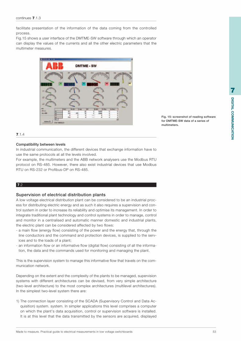
7
Dig
iTAl C
OM
Mu
niC
AT
iOn
Madetomeasure.Practicalguidetoelectricalmeasurementsinlowvoltageswitchboards 53
facilitate presentation of the information of the data coming from the controlledprocess.Fig.15showsauserinterfaceoftheDMTME-SWsoftwarethroughwhichanoperatorcandisplaythevaluesofthecurrentsandalltheotherelectricparametersthatthemultimetermeasures.
7.1.4
Compatibility between levelsInindustrialcommunication,thedifferentdevicesthatexchangeinformationhavetousethesameprotocolsatallthelevelsinvolved.Forexample,themultimetersandtheABBnetworkanalysersusetheModbusRTUprotocolonRS-485.However, therealsoexist industrialdevices thatuseModbusRTUonRS-232orProfibus-DPonRS-485.
7.2
Supervision of electrical distribution plantsAlowvoltageelectricaldistributionplantcanbeconsideredtobeanindustrialproc-essfordistributingelectricenergyandassuchitalsorequiresasupervisionandcon-trolsysteminordertoincreaseitsreliabilityandoptimiseitsmanagement.Inordertointegratetraditionalplanttechnologyandcontrolsystemsinordertomanage,controlandmonitor inacentralisedandautomaticmannerdomesticand industrialplants,theelectricplantcanbeconsideredaffectedbytwoflows:-amainflow(energyflow)consistingofthepowerandtheenergythat,throughthe
lineconductorsandthecommandandprotectiondevices,issuppliedtotheserv-icesandtotheloadsofaplant;
-aninformationfloworaninformativeflow(digitalflow)consistingofalltheinforma-tion,thedataandthecommandsusedformonitoringandmanagingtheplant.
Thisisthesupervisionsystemtomanagethisinformativeflowthattravelsonthecom-municationnetwork.
Dependingontheextentandthecomplexityoftheplantstobemanaged,supervisionsystems with different architectures can be devised, from very simple architecture(two-levelarchitecture) tothemostcomplexarchitectures (multilevelarchitectures).Inthesimplesttwo-levelsystemthereare:
1)TheconnectionlayerconsistingoftheSCADA(SupervisoryControlandDataAc-quisition)system.system.Insimplerapplicationsthislevelcomprisesacomputeronwhichtheplant'sdataacquisition,controlorsupervisionsoftwareisinstalled.It isatthislevelthatthedatatransmittedbythesensorsareacquired,displayed
continues 7.1.3
Fig. 15: screenshot of reading software for DMTME-SW data of a series of multimeters.

7
Dig
iTAl C
OM
Mu
niC
AT
iOn
54 Madetomeasure.Practicalguidetoelectricalmeasurementsinlowvoltageswitchboards
andprocessedandthecommandsaresent to theactuators. In thismanner,anoperatorcan, fromthesameposition,monitor thestatusof theentireplantandundertaketheoperationsrequiredtoensureefficiencyandcorrectoperation.Moreingeneral,inapplicationsinwhichtheelectricdistributionplantandthemanage-mentoftheprocessareintegratedthecontrollevelconsistsofthecomputersu-pervisingtheautomationsystemoftheentireindustrialprocess.
2)Thefieldlayerconsistingoffielddevicesprovidedwithacommunicationinterface(measuringinstruments,sensors,actuatorsandprotectionswitchesequippedwithelectroniccut-outmeans)installedintheelectricplantthatinteractdirectlywiththeplantandconnectitwiththecontrollevel.Themainfunctionsofthefieldlayerare:1)sendingtheplantdata(e.g.currents,voltages,energy,power,etc)tothecontrollayer2)actuating thecommands (e.g.opening/closureofswitches) received fromthecontrollayer
Thetwolayerscommunicatethroughabuscommunicationnetwork.Theinformation(e.g.measuredvalues)transmittedfromthefieldlayertothecontrolandcommandlevelthattravelsinanoppositedirection,constitutestheinformativeflowthattransitsonthebus.
supervision system for remote monitoring of electric parameters and energy consumption
mainpower panelANR144-230
motor 1 motor 2
Modbus RTU network
HVAC ANR96-24control
HVACsystem
monitoringof line 1
DMTME-I-485-96
productiveline 1
continues 7.2
Fig. 16: diagram of a supervision system with networked multimeters
an analysers.
Power flow
Info
rmat
ion
flow
Info
rmat
ion
flow
Info
rmat
ion
flow
Info
rmat
ion
flow

7
Dig
iTAl C
OM
Mu
niC
AT
iOn
Madetomeasure.Practicalguidetoelectricalmeasurementsinlowvoltageswitchboards 55
7.3
The Modbus RS-485 network
7.3.1
Rules for correct cablingThecablingoftheindustrialcommunicationsystemsisdifferentinsomewaysfromthecablingusedforpowercablingandtheelectricianmayexperiencesomedifficultiesifheisnotanexpertinModbuscommunicationnetworks.AModbusRS-485connectsaMasterdevicetooneormoreSlavedevices.Henceforth,weshallconsiderSlavede-vicestobeABBmeasuringinstrumentswithserialcommunication,evenifthecablingissimilarforallModbusdevices.Themainrulesaresetoutbelowthatmustbefollowedforthecablingofthistypeofnetwork.1.Connection port Eachdevicehasacommunicationportwithtwoterminals,whichareindicatedforthesakeofconvenienceasAandB.Inthesetwoterminalsthecommunicationcableisconnectedsothatallthedevicesthattakepartinthecommunicationareconnectedinparallel.Allthe'A'terminalsmustbeconnectedtogetherandallthe'B'terminalsmustbeconnectedtogetherrespectively;invertingthe'A'and'B'connectionsofadevicedoesnotonlypreventitfromcommunicatingbutmayalsostoptheentirecom-municationsystemfromworkingowingtoincorrectdirect(polarisation)voltagefoundontheterminalsof the incorrectlyconnecteddevice. Inorder toavoiderrorswhenmanydevicesareconnected,cablesof thesamecolourshouldbeused forall theconnectionstotheterminalsAandcablesofthesamecolourshouldbeusedforalltheconnectionstotheterminalsBofthevariousdevices(e.g.whiteforAandblueforB);thismakesiteasiertoidentifycablingerrors.ThecommunicationportontheMasterdevice,whateveritis,hastwoterminalsthatcorrespondtoAandB.2.Connection between the devicesUnlikewhathappensinmanyenergydistributionsystems,themannerinwhichthedevicesareconnectedinparallelisimportant.TheRS-485systemusedforModbuscommuncationprovidesamaincable(Busorbackbone),towhichallthedeviceshavetobeconnectedwithbranches(alsoknownasstubs)thatareasshortaspossible.Thebranchesmustbenolongerthan1200m.Longerbranchescouldcausesignalreflections and generate disturbances and consequent errors in the reception ofdata.Fig.17showsanexampleofacorrectBusconnection.
Main cable/Backbone (Bus)
Imax= 1 mStub
3.Maximum distance and maximum number of devices.Themaincablemustbeno longer than700m.Thisdistancedoesnot include thebranches(whichmustneverthelessbeshort).Themaximumnumberofdevicesthatcanbeconnectedtoamaincableis32,includingtheMaster.
Fig. 17: Network with Bus structure
Fig. 18: Examples of incorrect Bus connections

7
Dig
iTAl C
OM
Mu
niC
AT
iOn
56 Madetomeasure.Practicalguidetoelectricalmeasurementsinlowvoltageswitchboards
4.Use of repeatersInordertoincreasetheextentoftheModbusnetwork,repeaterscanbeused;andsignalamplifyingandregeneratingdevicesprovidedwith twocommunicationportsthattransfertoeachwhattheyreceivefromtheother.Usingarepeater,themainca-bleisdividedintodifferentsegments,eachofwhichcanbeupto700minlengthandconnect32devices (thisnumber includes the repeaters).Themaximumnumberofrepeatersthatshouldbeseriallyconnectedis3.Ahighernumberintroducesexces-sivedelaysinthecommunicationsystem.5.Type of cable to useThe cable to be used is a shielded twisted pair (telephone type). ABB specifies aBelden3105Acable,butdifferenttypesofcablewithequivalentcharacteristicscanbeused.Thetwinconsistsoftwoconductorsthataretwistedtogether.Thisarrange-mentimprovesimmunitytoelectromagneticdisturbancesbecausethecableformsaseriesofsuccessivecoils,eachofwhichfacesintheoppositedirectiontothenextone:inthismanneranymagneticfieldintheenvironmenttraverseseachpairofcoilsinoppositedirectionsanditseffectisthusveryreduced(theoretically,theeffectoneachcoil isexactlytheoppositeoftheeffectonthenextoneandthustheeffectiscancelled).Theshieldingmaybebraided (be formedbyameshof thinconductingwires)orbeafoil(consistingofasheetofmetalwoundaroundtheconductors):thetwotypesareequivalent.
sheath shield(foil-type)
twistedpair
earthingof shield
6.Connecting to the terminals Insomecountries,insertingtwocablesintothesamescrewterminalispermitted.Inthiscaseitispossibletoconnectthemaininletandoutletterminaldirectlytotheter-minalsofaninstrumentwithoutcreatingabranch.Ifontheotherhandeachterminalcanacceptonlyasinglecable,aproperbranchmustbecreatedusingthreeauxiliaryterminalsforeachinstrumenttobeconnected.7.Earth connection of the shieldThecableshieldmustbeearthedonlyinonepoint.Normally,thisconnectionismadeatoneendofthemaincable.8.Termination resistanceInordertoavoidsignalreflections,a120Ohmterminationresistancemustbefittedoneachendofthemaincable.Theendresistancemustbeusedonlyattheendsofthemaincable.Ifthetotallengthofthemaincableislessthan50mterminationre-sistancescanbeavoidedattheendsofthemaincable.
Fig. 19 : Detail of a shielded twisted pair.
Fig. 20 : 120 Ohm resistance connection
continues 7.3.1

7
Dig
iTAl C
OM
Mu
niC
AT
iOn
Madetomeasure.Practicalguidetoelectricalmeasurementsinlowvoltageswitchboards 57
9.Connection to personal cmputerIfthemasterusedisapersonalcomputer,ingeneralanRS-232/RS-485serialconverterprovidestheconnectiontothebus.
7.3.2
The operation of the Modbus systemThetrafficoftheinformationonthebusismanagedbyaMaster/SlaveprocedurewiththePCorthePLCactingasaMasterandtheswitchesactingasSlaves.TheMasterdirectsallthetrafficofthebusandonlytheMastercaninitiatethecommunication.Ittransmitsdataand/orcommandstotheSlavesandasksthemtotransmitthedata.TheSlavestransmittothenetworkwhenrequestedtodosobytheMaster.TheSlavescan-notcommunicatedirectlywithoneanother:forexample,totransferadataitemfromoneSlavetoanothertheMastermustreadthedataitemfromthefirstSlaveandtrans-ferittothesecond.Thecommunicationsequencebetweeneachmultimeter(Slave)andthePC(Master)occursinthefollowingmanner:1)ThePCsendsacommandorquerytothebus.2)the interrogatedmultimeterprovidesa responseby taking theappropriateaction,
whichmaybe:-runningthereceivedcommand;-providingtherequesteddataor-informingitthattherequestcannotbemet.Thecommandortherequestcontainstheidentificationoftheinstrumenttowhichthecommunicationhasbeensentandtherefore,althoughthetransmissionhasbeenre-ceivedbyallthedevicesconnectedtothenetwork,normallyonlythedeviceconcernedwillrespond.TheswitchesareinterrogatedbythePCthroughcyclicalpolling,i.e.oneatatimecylicallysoastocompletelyscantheplantwithinasettime(pollingtime).Thecalculationofpollingtimeconsiderscomputerprocessingtime,tPC,tobenegligible,i.e.thetimethatelapsesbetweentheendoftheRESPONSEofaninstrumentandthestartofaQUERYthatthecomputersendstothenextinstrument.
WhatisneededtoimplementaModbusRTUsystemwithABBmeasuringinstrumentsandhowdoestheModbusprotocolactuallywork?
Whatisneeded:-master,whichmaybeaPCoraPLCoraSCADA-ifthemasterisaPCwithaserialinputportRS232,thenetworkofinstrumentsmust
beinterfacedwiththemasterbyaserialconverter232/485-connectioncablebetweentheconverterandPCthatmayhaveserialsocketsorUSB
inputs-shieldedtwistedpair(telephonetype),asdescribedinparagraph7.3.1-instrumentswithaserialportRS485,consistingofaterminalboardwith3terminals
ontheinstrumentmarkedABC.
InordertobeabletoimplementaModbusRTUcommunicationnetworkbetweensev-eralslavescomunicatinginModbusRTU,whethertheybemeasuringinstruments,pro-tectionswitches,ortemperaturecontrolunit, it isfundamentaltosetthesamecom-municationparametersonalltheobjectsinthenetwork.Thecommunicationparametersare:-datatransmissionspeed,knownasthebaudrate:from2400bpsto19200bps-databit:8-paritynumber:Even,Odd,None-stopbit1,2(ifparitynumber=none),1(ifparitynumber=even,oddornone)-addressforeachslave
Oncethesamebaudrate,paritynumberandstopbithasbeenset,andaftereachslavehasbeengivenitsownuniqueaddress,it ispossibletoacquireinformationfromthemaster.
continues 7.3.1

7
Dig
iTAl C
OM
Mu
niC
AT
iOn
58 Madetomeasure.Practicalguidetoelectricalmeasurementsinlowvoltageswitchboards
Themastercommunicateswiththeslavesbysendingrequestsforinformationorqueries,andtheslavescommunicatewiththemasterbysendinganswers,knownasresponses,tothemaster.Theslavesareinterrogatedonebyonebythemaster,soifthenetworkisverycomplexintermsofthenumberofinstrumentsconnectedandthephysicaldistancebetweenthem,responsetimesincrease.TheModbusnetworkcanmanageupto247instruments.Themaximumdistancethatcanbecoveredis1200m;beyondthatdistanceasignalrepeatermustbeusedthatamplifiesthesignalandenablesdistancesthataregreaterthan1200mtobecovered.Themessagethatthemastersendstotheslaveisan8bitmessagewhereeachpartofthemessagehasameaning.Thefirstpartofthemessageisthephysicaladdressoftheslavetobeinterrogated.Subsequently,thefunctionisindicatedthatitisdesiredtoperform;thefunctionsaretypi-cally readingparameters,writingset-upsettings in the instrumentasa transformationratiooftheCTandoftheVT,andfunctionsforacquiringtherecordofthenetworkedproduct.Thecentralpartofthemessageindicateswhatandhowmuchinformationisrequired.Lastly,theclosurebitscheckthatthemessagehasarrivedandhasbeende-cypheredbythecorrectinstrument.
Theinformationthatthemasterrequestsfromameasuringinstrumentarethevaluesofthemeasuredandcalculatedelectricalparameters.Thelistofthesevaluesislocatedintheinstrumentonalist,eachparameterhasitspositioninsidethislist;thelistisknownasamemorymapandeachposition is indicatedasaregister,which iswhy it isalsoknownastheregistersmap.Thememorymapisthusthelistofalltheregisterscontain-ingtheparametersreadbytheinstrument.Thefollowingtableshowsthecorrespondencebetweentheaddressofeachposition,thelengthoftheresponsestring(2meansthattheslavewillrespondwithtwovalues,thefirstofwhichindicatestheparametermark),thedescriptionoftheelectricparameter,theunitofmeasurementandthebinaryformat.
Address Word Measurementdescription Unit Format1000h 2 3-PHASESYSTEMVOLTAGE Volt UnsignedLong1002h 2 PHASEVOLTAGEL1-N Volt UnsignedLong1004h 2 PHASEVOLTAGEL2-N Volt UnsignedLong1006h 2 PHASEVOLTAGEL3-N Volt UnsignedLong1008h 2 LINEVOLTAGEL1-2 Volt UnsignedLong100Ah 2 LINEVOLTAGEL2-3 Volt UnsignedLong100Ch 2 LINEVOLTAGEL3-1 Volt UnsignedLong100Eh 2 3-PHASESYSTEMCURRENT mA UnsignedLong1010h 2 LINECURRENTL1 mA UnsignedLong1012h 2 LINECURRENTL2 mA UnsignedLong1014h 2 LINECURRENTL3 mA UnsignedLong1016h 2 3-PHASESYS.POWERFACTOR *1000 SignedLong1018h 2 POWERFACTORL1i *1000 SignedLong101Ah 2 POWERFACTORL2i *1000 SignedLong101Ch 2 POWERFACTORL3i *1000 SignedLong101Eh 2 3-PHASESYSTEMCOSi *1000 SignedLong1020h 2 PHASECOS1i *1000 SignedLong1022h 2 PHASECOS2i *1000 SignedLong1024h 2 PHASECOS3i *1000 SignedLong1026h 2 3-PHASES.APPARENTPOWER VA UnsignedLong1028h 2 APPARENTPOWERL1 VA UnsignedLong102Ah 2 APPARENTPOWERL2 VA UnsignedLong102Ch 2 APPARENTPOWERL3 VA UnsignedLong102Eh 2 3-PHASESYS.ACTIVEPOWER Watt UnsignedLong1030h 2 ACTIVEPOWERL1 Watt UnsignedLong1032h 2 ACTIVEPOWERL2 Watt UnsignedLong1034h 2 ACTIVEPOWERL3 Watt UnsignedLong1036h 2 3-PHASES.REACTIVEPOWER VAr UnsignedLong1038h 2 REACTIVEPOWERL1 VAr UnsignedLong103Ah 2 REACTIVEPOWERL2 VAr UnsignedLong103Ch 2 REACTIVEPOWERL3 VAr UnsignedLong103Eh 2 3-PHASESYS.ACTIVEENERGY Wh*100 UnsignedLong1040h 2 3-PHASES.REACTIVEENERGY VArh*100 UnsignedLong1046h 2 FREQUENCY mHz UnsignedLong1060h 2 MAXLINECURRENTL1 mA UnsignedLong1062h 2 MAXLINECURRENTL2 mA UnsignedLong1064h 2 MAXLINECURRENTL3 mA UnsignedLong1066h 2 MAX3-PHASESYS.ACTIVEPOWER Watt UnsignedLong1068h 2 MAX3-PHASES.APPARENTPOWER VA UnsignedLong1070h 2 3-PHASESYS.ACTIVEPOWER15'AVER Watt UnsignedLong11A0h 2 CURRENTTRANSFORMRATIO(CT) 1-1250 UnsignedLong11A2h 2 VOLTAGETRANSFORMRATIO(VT) 1-500 UnsignedLong11A4h 2 PULSEENERGYWEIGHT 1-4ii UnsignedLong
Fig. 21 : Memory map registers map of DMTME multimeters
continues 7.3.2

7
Dig
iTAl C
OM
Mu
niC
AT
iOn
Madetomeasure.Practicalguidetoelectricalmeasurementsinlowvoltageswitchboards 59
Forexample,ifIwanttoknowthevalueofthethree-phasevoltage,themasterwillhavetosendacommandconsistingof:-addressoftheinstrumentthatIwishtointerrogate(forexampleamultimeterlocated
onthemaincontrolpaneloftheplant)-readingfunction-addressoftheregisterofthe'three-phasevoltage'value-howmanyotherparametersiwanttoread,upto5-testingandcheckingthatthemessagehasreacheditsdestination
Thestringsentbythemasterhasthefollowingformat:
AddressField = 1FhFunctionCode = 03hStartAddressH = 10hStartAddressL = 00hNo.ofregisterH = 00hNo.OfregisterL = 14hCRCH = 42hCRCL = BBh
Intheaboveexample,themastersendsa03hreadingfunctiontotheslavewiththeaddress1Fh,startingfromtheparameterofthe1000hregisterfor14registers.
Theresponsesentbytheslavehasthefollowingformat:
AddressField = 1FhFunctionCode = 03hBytecount = 28hDataReg1000H = 10hDataReg1000L = EFh-------------------------------CRCH = XxhCRCL = Yyh
Analysingthemaponthe1000hregisterthereisthevoltageofthethree-phasesystem.Thusstartingfromthefirstregisterfor14registers,thePowerFactorvalueuptophase2isread.
Thevaluesoftheregistersinthememorymapareexpressedashexadecimalvalues.WhenusingfreewarereadingsoftwaredownloadedfromtheWebsuchasModbusPollorModbusContructorthatenablethedatareadbyamultimetertobeacquired,caremustbe takenoverwhether hexadecimal ordecimal valuesare requested from thesoftware.
Forexample,thethree-phasevoltagevalueisinthehexadecimalregister1000,whichbecome4096ifconvertedintodecimals.
Thememorymapissetbythemanufacturer,whodecideswhichregistershouldbeas-sociatedwiththeparameterreadbythemultimeter,andalsodecideswhetheralltheread and setting parameters of the instruments can be transmitted via serialcommunication.WhoneedstheregistersmapofaModbusRTUinstrument?ItisnormallytheSystemIntegratorwhohastoimplementthecommunicationnetworkviaPCorPLC.Thisisthepersonwhoimplementscommunicationbetweenthevariousdevicesconnectedtothebus.Theregistersmapisrequiredtoindicatetothemastertheaddressesinwhichelectricalquantitiesarefound.
continues 7.3.2

60 Madetomeasure.Practicalguidetoelectricalmeasurementsinlowvoltageswitchboards
load
8Applicational examples of network analysers
Anapplicationalexampleisgivenbelow,withtherelativeinstructionsforsettinganduseoftheANRrangenetworkanalyser.Theapplicationintheexamplereferstoanindustrialplantortoatertiarysector(majorretailing)plantwithmixedlinearandnon-linearloads.TheANR144instrumentisinstalledinthelowvoltageMainPowerPanel.
Connectitinaccordancewiththeinstructionsthatfollow
Thesupplyfortheoperationoftheinstrumentcanbetakendirectlyfromthesupplyline(ANR144-230).
Fig. 1: Network analyser ANR144
Fig. 2: Wiring diagram for inserting ANR in three-phase network
with neutral. Insertion on 4-wire line with 3 CTs and 3 VTs
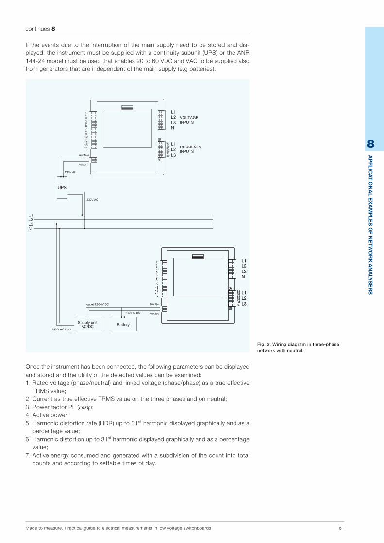
8
AP
PliC
AT
iOn
Al E
xA
MP
lEs
Of n
ET
wO
rk
An
Aly
sE
rs
Madetomeasure.Practicalguidetoelectricalmeasurementsinlowvoltageswitchboards 61
continues 8
If theeventsdueto the interruptionof themainsupplyneedtobestoredanddis-played,theinstrumentmustbesuppliedwithacontinuitysubunit(UPS)ortheANR144-24modelmustbeusedthatenables20to60VDCandVACtobesuppliedalsofromgeneratorsthatareindependentofthemainsupply(e.gbatteries).
Oncetheinstrumenthasbeenconnected,thefollowingparameterscanbedisplayedandstoredandtheutilityofthedetectedvaluescanbeexamined:1.Ratedvoltage(phase/neutral)andlinkedvoltage(phase/phase)asatrueeffective
TRMSvalue;2.CurrentastrueeffectiveTRMSvalueonthethreephasesandonneutral;3.PowerfactorPF(cosϕ);4.Activepower5.Harmonicdistortionrate(HDR)upto31stharmonicdisplayedgraphicallyandasa
percentagevalue;6.Harmonicdistortionupto31stharmonicdisplayedgraphicallyandasapercentage
value;7.Activeenergyconsumedandgeneratedwithasubdivisionofthecountintototal
countsandaccordingtosettabletimesofday.
Fig. 2: Wiring diagram in three-phase network with neutral.
BatteriaAlimentatorec.a./c.c.
VOLTAGEINPUTS
CURRENTSINPUTS
Supply unitAC/DC
230 V AC input
outlet 12/24V DC
Battery
12/24V DC
230V AC
230V AC

8
AP
PliC
AT
iOn
Al E
xA
MP
lEs
Of n
ET
wO
rk
An
Aly
sE
rs
62 Madetomeasure.Practicalguidetoelectricalmeasurementsinlowvoltageswitchboards
8.1
Rated voltage (phase/neutral) and linked voltage (phase/phase) as a true effective TRMS valueMeasuringvoltageisoneofthemainparametersforbeingabletoconductthenet-workanalysis.Itisalsousedtoassessthestateofbalanceofthevoltageonthethreephasesduringnormaloperationoftheplant.
8.2
Current as true effective TRMS value on the three phases and on neutralMeasuringcurrentsisoneofthemainparametersforbeingabletoconductthenet-workanalysis.Itisalsoimportantforcheckingthatloadsarecorrectlydistributedoverthethreephases.MeasuringtheneutralcurrentasatrueeffectiveTRMSvalueisimportantforestab-lishingwhethernon-linearloadsintroduceadistortionofthethirdharmonicasindi-catedinpoint6.2.-Iftheloadsarebalancedandtherearenoharmonicdistortions,thecurrentonthe
neutralconductorisvirtuallynil;-innormalconditions,withloadsthatarenotbalancedbutintheabsenceofharmon-
ics,theneutralcurrentismuchlessthanthephasecurrent;-inthepresenceofharmonicdistortionthethirdharmoniclinecurrentsareaddedto
neutralbecausetheyarephasedtogetherandaneutralcurrentoccursthatisgreaterthehigherthevalueofthethirdharmoniccurrents.
8.3
Power factor PF (cosϕ)Thepowerfactor,whichisbetterknownwiththetermcosϕ,mustbemaintainedatavaluethatisascloseaspossibleto1.MeasuringthepowerfactorPF is importanttoavoidhavingtopaypenaltiestothesupplieroftheelectricenergyforPFvaluesbelow0.9.AnalarmthresholdshouldbeinsertedforthismeasurementtowarntheuserifthePFgetsnearthe0.9value(e.g.alarmtrippedat0.92)
Fig. 5: Display of cosphi values
and power factor.
Fig. 4: Display of page dedicated to phase and neutral currents.
Fig. 3: Display of the parameters of the three-phase system.

8
AP
PliC
AT
iOn
Al E
xA
MP
lEs
Of n
ET
wO
rk
An
Aly
sE
rs
Madetomeasure.Practicalguidetoelectricalmeasurementsinlowvoltageswitchboards 63
8.4
Active powerAsmentionedinchapters1.5and1.6,inordertoavoidpenalties,it isimportanttocontrolandmanageabsorptionpeakssoastoneverexceedtheaverageofavailablepower.Forcorrectmanagementandoptimisationofconsumption,theinstrumentcanbeprogrammedinsuchawaythat:-Consumptionisrecordedforanalysis,alsofortimesofday,inrelationtothesupply
contract;-Theloadsthatcanbedisconnectedwiththeleastgraveconsequencesbythein-
strumentshouldbesetfordisconnectionintheeventoftheavailablepowerthresh-oldbeingexceeded.
8.5
Total harmonic distortion rate (THD) up to 31st harmonic displayed graphically and as a percentage value DisplayingandstoringtheTHDenablesthetotalharmonicpercentageoftheloadsintheplanttobeassessedovertime.
8.6
Harmonic distortion up to 31st harmonic displayed graphically and as a percentage valueIftheprecedingmeasurementdetectsaharmoniccontentintheelectricplant,ananalysisoftheharmonicspresent,uptothe31stharmonic,canbeconducted,displayingthephe-nomenabothgraphicallyandasapercentagevalue.Whentheharmonicdistortionreacheshighlevels,differentproblemsmayarise,assetoutinpoint6.2.
8.7
Active energy consumed and generated with a subdivision of the count into total counts and according to settable times of day.Thisfunction isparticularlyuseful fortestingandthebalancebetweenenergycon-sumedfromthenetworkandenergyproducedinthecaseofself-generation.
Fig. 8: Display of harmonic analysis up to 31st order, numeric and graphic representation.
Fig. 6: Display of active power.
Fig. 7: Display of percentage THD values for voltages and currents.
64 Madetomeasure.Practicalguidetoelectricalmeasurementsinlowvoltageswitchboards
9Annex
9.1
Measurements Glossary
Accessory Element.Groupofelementsordeviceassoci-atedwiththemeasuringcircuitofameasuringinstrument to supply characteristics specifiedforthemeasuringinstrument.
Amplitude of the measuring field Algebricdifferencebetween thevaluesof theupperlimitandofthelowerlimitofthemeasur-ingfield.Itisexpressedinunitsofthemeasuredquantity.
Measuring range (actual range) Field defined by two values of the measuredquantity, in which the margins of error of ameasuring instrument (and/or accessory) arespecified.
Auxiliary circuit Circuit,other thanameasuringcircuit, that isnecessaryfortheoperationoftheinstrument.
Measuring circuit (of an instrument) Partoftheelectriccircuitlocatedinsidethein-strumentanditsaccessories,togetherwithanyconnectioncords,suppliedbyvoltageoracur-rent,oneorboththesequantitiesbeinganes-sential factor for determining the measuredquantity(oneofthesequantitiescanbetheac-tualmeasuredquantity).
Accuracy rating Groupofmeasuringinstrumentsand/oracces-soriesthatmeetcertainmeasuringprescriptionsthataredesignedtokeeperrorsandvariationswithinthespecifiedlimits.
Reference conditions Appropriatesetofspecifiedvaluesandofspeci-fiedfieldsofvaluesof the influencequantitiesforwhich thepermissibleerrors foran instru-ment and/or for an accessory are specified.Each influencequantity canhavea referencevalueorareferencefield.

9
An
nE
x
Madetomeasure.Practicalguidetoelectricalmeasurementsinlowvoltageswitchboards 65
continues 9.1
Measuring cord Cordcomprisingoneormoreconductors,whichhas been specially designed for connectingmeasuringinstrumentstoexternalcircuitsortoaccessories.
Shunt Resistorconnected inparallel toameasuringcircuitofameasuringinstrument.
Division Distance between any two consecutive seg-mentsofascale.
Error (absolute) Foraninstrument,avaluethatisobtainedbysubtracting the true value from the indicatedvalue. Foranaccessory,avaluethat isobtainedbysubtractingthetruevaluefromthe(expected)markedvalue. N.B.:
1 As the true value cannot be obtained through a measurement, a value is used in its place that is obtained in specified test conditions in a specified instant. This value derives from national measuring samples or from measur-ing samples agreed between the manufac-turer and the user.
2 Attention is drawn to the fact that an acces-sory error can be transformed into the oppo-site type of error when this accessory is as-sociated with an instrument.
Scale error Difference between the value indicated by ameasuringinstrumentandtheproportionalval-ueofthequantitymeasuredatdifferentpointsofthescaleaftertheinstrumenthasbeencali-bratedso that itdoesnothaveerrorsat twopoints.
Error (intrinsic) Errorofaninstrumentand/orofanaccessoryplacedinthereferenceconditions.
Phasemeter Instrumentthat indicatesthephaseanglebe-tweentwoelectricinputquantitiesofthesamefrequencyandwithasimilarwaveshape.
Thisinstrumentmeasures: -thephaseanglebetweenonevoltageandan-
othervoltageorbetweenonecurrentandan-othercurrent.
or -the phase angle between a voltage and a
current.
Distortion factor Ratio:(factor of total harmonic distortion effectivevalueofthenon-sinusoidalquantityof a quantity) effectivevalueoftheharmoniccontent
Peak factor Ratiobetweenthepeakvalueandtheeffectivevalueofaperiodicquantity.

9
An
nE
x
66 Madetomeasure.Practicalguidetoelectricalmeasurementsinlowvoltageswitchboards
continues 9.1
Graduation Segmentsplacedonthedialtodividethescaleintoappropriate intervals soas toenable thepositionoftheindextobedetermined.
Index Component(means)thatisassociatedwiththescaleandindicatesthepositionofthemovableelementofaninstrument.
Class index Numberthatindicatestheaccuracyrating. Note: some instruments and/or accessories may have
more than one class index.
Length of the scale Lengthoftheline(cuvedorstraight)thatpassesthrough the middle points of all the shortestsegmentsofthegraduation,includingbetweenthefirstandthelastsegmentofthescale.Itisexpressedinunitsoflength.
Power factor meter Instrumentdesignedtomeasuretheratiobe-tweentheactivepowerandtheapparentpowerofanelectriccircuit.
Accuracy Forameasuringinstrument,itisthequalitythatcharacterisesthedegreeofproximitybetweentheindicatedvalueandthetruevalue.Foranaccessory,itisthequalitythatcharacterisesthedegreeofproximitybetweentheindicated(ex-pected)valueandthetruevalue.
Note: the accuracy of a measuring instrument and/or
of an accessory is defined by the intrinsic error and by the limits of the variations.
Dial Surfaceonwhichthescaleandotherinscrip-tionsandsymbolsarelocated.
Resistor (impedance) Resistor(impedance)seriallyconnectedtoan additional measuringcircuitofameasuringinstrument.
Scale Theentiregraduationandallthenumbersfromwhich,incombinationwiththeindex,thevalueofthemeasuredquantityisobtained.
Overshoot Difference(expressedasafractionofthelengthofthescale)betweenthemaximumtransitoryindicationandthepermanentindicationwhenthemeasuredquantitychangessuddenlyfromoneconstantvaluetoanotherconstantvalue.
Analogue display instrument Measuring instrument intended forpresentingordisplayingtheoutletinformationasacontinu-ousfunctionofthemeasuredquantity.
Note: an instrument in which a variation of the indica-
tion occurs by small discrete steps but which does not have a numeric display is considered to be an analogue instrument.
9
An
nE
x
Madetomeasure.Practicalguidetoelectricalmeasurementsinlowvoltageswitchboards 67
continues 9.1
Instrument with a response Instrument that in a specified frequency fieldas an effective value providesanindicationthathastobeproportional
totheeffectivevalueofthemeasuredquantity,evenwhenthemeasuredquantityisnotsinu-soidalorhasacontinuouscomponent.
Electric measuring instrument Measuringinstrumentdesignedtomeasureanelectricquantityoranon-electricquantityusingelectricmeans.
Electronic measuring instrument Measuringinstrumentdesignedtomeasureanelectricquantityoranon-electricquantityusingelectronicmeans.
Direct-action indicating instrument Instrumentinwhichtheindicatingdeviceiscon-nected mechanically to the movable elementandisdrivenbytheelement.
Ripple rate (content) Ratio:(of a quantity) effectivevalueofthecontinuouscomponent effectivevalueoftheripplecomponent
Response time Timerequiredfortheindicationtofirstenterandthenremainwithinarangecentredonthefinalpermanentindicationwhenthemeasuredquan-tityvariessuddenlyfromzero(correspondingtonon-suppliedstatus)toavaluethatissuchthatthe final permanent indication is a specifiedpointonthescale.
Assigned value Valueofaquantityfixed,generallybythemanu-facturer,foraspecifiedoperatingcondition.
Conventional value Clearlyspecifiedvalueofaquantitytowhichtheerrorsofaninstrumentand/orofanaccessoryrefer,inordertodefinetheirrespectivedegreeofaccuracy.
Rated value Valueofaquantitythatindicatestheenvisageduseofaninstrumentoranaccessory.
Theprescribedcharacteristicsoftheinstrumentsandtheaccessoriesarealsonominalvalues.
Graduation zero Segmentofthedialassociatedwiththenumberzero.
Contact us
System pro M compact®
DIN Rail components for low voltage installation
Technical catalogue - Edition 2011
Contact usContact us
2CS
C40
0002
D02
09 -
Jan
uary
201
1 -
14.0
00ABB SACE a division of ABB S.p.A.ABB STOTZ-KONTAKT GmbH
In consideration of modifications to Standards and materials, the characteristics and overall dimensions indicated in this catalogue may be considered binding only following confirmation by ABB
Copyright 2011 ABB. All rights reserved.
System
pro
M co
mp
act® D
IN R
ail components for low
voltage installation
2CSC400002D0209
Ifyourequirefurtherdetails,youcanorderthetechnicalliteratureillustratedheredirectlyon-linefromthehomepageofourwebsitehttp://www.abb.com/abblibrary/DownloadCenter/inthe“Orderdocumentationandtechnicalsoftware”section.
System pro M compact®


Mad
e to measure. P
ractical guide to electrical m
easurements in low
voltage switchb
oards
(a)
(b)V
t
V
t
(f)50 Hz
A
050
100
150
200250 500
A
050
100
150
200250 500
V
0
8060
40
20
Made to measure.Practical guide to electrical measurements in low voltage switchboards
2CS
C44
5012
D02
01 -
03/
2011
- 1
.500
- C
AL.
Contact us
ABB SACEUna divisione di ABB S.p.A.Apparecchi ModulariViale dell’Industria, 1820010 Vittuone (MI)Tel.: 02 9034 1Fax: 02 9034 7609
bol.it.abb.comwww.abb.com
The data and illustrations are not binding. We reserve the right to modify the contents of this document on the basis of technical development of the products,without prior notice.
Copyright 2011 ABB. All rights reserved.